sealed combustion system - dms.hvacpartners.com · vtk-1 vtk-2 vtk-3/ klavt0201det vtk-098/...
TRANSCRIPT
Printed in Canada Printed on 100% recycled paper
2011-06-30 X40142 Rev. G
SEALED COMBUSTION
SYSTEM (DIRECT VENT)
Manufactured by:
Dettson Industries inc. 3400 Industrial Boulevard Sherbrooke, Quebec - Canada J1L 1V8
INSTALLER / SERVICE TECHNICIAN : USE THE INFORMATION IN THIS MANUAL FOR THE INSTALLA TION AND SERVICING OF THE FURNACE AND KEEP THE DOCUMENT NEAR THE UNIT FOR FUTURE REFERENCE.
HOMEOWNER : PLEASE KEEP THIS MANUAL NEAR THE FURNACE FOR FUTURE REFERENCE.
ATTENTION: Do not alter the unit or its controls. Call a qualified service
DNA1074 Rev. A
Models :
VTK-1 VTK-2 VTK-3/ KLAVT0201DET VTK-098/ KLAVT0101DET

3
1.0 SAFETY REGULATIONS 1.1 SAFETY LABELING AND WARNING SIGNS The words DANGER, WARNING AND CAUTION are used to identify the levels of seriousness of certain hazards. It is important that you understand their meaning. You will notice these words in the manual as follows:
DANGER
Immediate hazards that WILL result in death, serious bodily injury and/or property damage.
WARNING
Hazards or unsafe practices that CAN result in death, bodily injury and/or property damage.
CAUTION
Hazards or unsafe practices that CAN result in bodily injury and/or property damage.
WARNING
Installations or repairs performed by unqualified persons can result in hazards to them and to others . Installations must conform to local codes or, in th e absence of same, to codes of the country having jurisdiction.
The information contained in this manual is intende d for use by a qualified technician, familiar with safety procedures and equipped with the proper tools and t est instruments.
Failure to carefully read and follow all instructio ns in this manual can result in death, bodily injury and/ or property damage.
1.2 IMPORTANT NOTICE
WARNING
If the advice given in this manual is not heeded, i t will lead to consequences resulting in death, serious bo dily injury and/or property damage.
a) It is the homeowner’s responsibility to engage a qualified technician for the installation and subsequent servicing of this venting system.
b) Do not start the heating system if any part of i t is
immersed in water. Call a qualified service technician immediately, to assess the damage and to replace all critical parts that are in contact w ith water.
c) Do not store gasoline or any other flammable
substances, such as paper, carton, etc. near the furnace.
2.0 INSTALLATION
WARNING
Do not enclose the vent pipe in a ceiling or combus tible structure.
All local and national code requirements governing the installation of oil burning equipment, wiring and flue connection MUST be followed. Some of the codes that may apply are:
CSA B139: Installation Code for oil burning equipment.
ANSI/NFPA 31: Installation of oil burning equipment.
ANSI/NFPA 90B: Warm air heating and air conditioning systems.
ANSI/NFPA 211: Chimneys, Fireplaces, Vents and solid fuel burning Appliances.
ANSI/NFPA 70: National Electrical Code
CSA C22.1: Canadian Electrical Code
or CSA C22.10
Only the latest issues of these codes may be used.
This sealed combustion system, must be installed in strict accordance with this manual. A 3" (7.62 cm) diameter outdoor combustion air pipe must be connected direc tly to the oil burner and the coaxial vent terminal to ensure the proper functioning to the unit. Only Beckett AFII and NX burners, as well as Riello BF type burners may be used with this sealed combustion system (VTK/KLAVT). A Sealed Combustion System is by definition a leak-free system. DO NOT PERFORATE THE VENT OR OUTDOOR COMBUSTION AIR PIPE! Use the test port in the breech plate supplied with this kit to take smoke and CO2 readings. Refer to Table 2 for the minimum and maximum dimensions of the vent pipe. 2.1 POSITIONING
WARNING
Poisonous carbon monoxide gas hazard.
Even though the flexible venting is insulated, it m ust not be run through an unheated space.
To do so can cause residual condensation inside the stainless steel liner. This may eventually perforat e the liner and allow vent gasses to enter the dwelling, potentially resulting in death, personal injury and /or, property damage.
The minimum clearance of the vent pipe in relation to combustible material is specified in Table 1 below. This clearance must be maintained all along the pipe.
4
TABLE 1 Minimum clearance around a vent system
PORTION OF VENT CANADA AND
UNITED STATES Vent pipe, up to vent terminal* 3" (7,62 cm) Vent terminal Zero
*Do not enclose venting.
WARNING
Do not enclose the vent pipe in a ceiling or combus tible structure.
FIGURE 1
The interior portion of the vent terminal must be installed in an area where the temperature of the ambient and return air is higher than 60°F (15°C). In addition, the furnace should be located as closely as possible to the vent terminal, so that the ducts are as short and direct as possible.
TABLE 2
MODEL VENT PIPE
INSIDE. DIA.
MAX. LENGTH
VENT PIPE
MIN. LENGTH
VENT PIPE
VTK-1 3.25” (8,26 cm) 20' (6,10 m) 3’ (0,91 m) VTK-2 4” (10,16 cm) 20' (6,10 m) 3’ (0,91 m) VTK-3/
KLAVT0201DET 5” (12,70 cm) 20' (6,10 m) 3’ (0,91 m)
VTK-098/ KLAVT0101DET
4” (10,16 cm) 20' (6,10 m) 3’ (0,91 m)
Installation considerations The vent may be installed through a wall with a minimum thickness of 2" (5,08 cm) and a maximum thickness of 15" (38,10 cm). Select a location for the vent terminal in accordance with all local and national codes. The following requirements shall be considered to be minimum
requirements that can be overridden by stricter local and national codes.
CAUTION
Ensure that the area around the side wall venter is always free of snow, ice and debris, since these will hamper the proper functioning of the furnace.
The vent shall not terminate: a. Directly above a paved sidewalk or paved driveway that
is located between two buildings, and that serves both buildings;
b. Less than 7' (2.13 m) above any paved driveway;
c. Within 6' (1.82 m) (in Canada) of a window or door, or mechanical air supply inlet to any building;*
d. Within 6' (1.82 m) (in Canada) from the soffit of the roof of the structure;*
e. Above a gas meter/regulator assembly within 3' (0.91 m) of a vertical centreline of the regulator;
f. Within 6' (1.82 m) of any gas service regulator vent outlet, or within 3' (0.91 m) of an oil tank vent, or an oil fill inlet;
g. Within less than 1' (0.30 m) above ground level;
NOTE : The vent must be located at least 1' higher than the highest anticipated accumulation of snow.
h. Within 6' (1.82 m) of any other combustion air inlet;
NOTE : It is possible that, when the system in not in operation, combustion products may reach the interior of the building.
i. Within 6' (1.82 m) of a property line;
j. Underneath a veranda, porch or deck;
k. So that the flue gasses are directed at combustible material or any openings of surrounding buildings that are within 6' (1.82 m);
l. Less than 3' (0.91 m) from an inside corner of an "L"-shaped structure;
m. So that the bottom of the vent termination opening is less than 1' (0.30 m) above any surface that may support ice, snow, or debris;
n. So that the flue gasses are directed toward brickwork, siding or other construction, in such a manner that they will be damaged from heat or condensation from flue gasses.
CAUTION
Most codes have a notwithstanding clause which states that products of combustion shall not enter the dwelling under any circumstances, even if all other code requirements as to construction and location have been complied with. The installer is ultimately responsible to do whatever is necessary to ensure that flue gasses do not enter the dwelling.
* For installations in the U.S.A. refer to Section 6.7.3.4 of the NFPA 31.

5
FIGURE 2
2.2 INSTALLATION OF THE COMPONENTS Refer to Figure 2 for additional details on components identification. Installing the terminal in the wall 1. Open up a 6" (15,24 cm) hole for the VTK-
098/KLAVT0101DET, VTK-1 and VTK-2 terminals and a 6¼” (15,88 cm) hole for the VTK-3/KLAVT0201DET terminal in the wall in accordance with the location considerations outlined in the previous section (2.1);
2. Fasten the wall plate to the inside-wall using 4 field-supplied fasteners, appropriate for the wall material. Note that the pressure control bracket (item G) must be removed to access the top right wall plate screw hole (item E). Install the wall plate so that the top of the hole in the wall plate is positioned 1/8" (3.2 mm) higher than the top of the 6" (15,24 cm) hole in the wall, see Figure
3. This will ensure the proper slope of the terminal for the proper evacuation from the inside to the outside;
3. Remove the 3 screws (item C) holding the end cone (item A) in place and remove the cone;
4. Remove the 4 screws (item C) holding the stabiliser shroud (item B) in place and remove the stabiliser shroud;
5. Insert the main body of the terminal through the wall plate so that the end of the terminal extends about 2" (5.08 cm) past the outside wall, see Figure 3;
6. Install the stabiliser shroud (item B), as shown in Figure 4 and replace the 4 mounting screws;
7. On concrete and block wall installations in particular, if it appears that the flange on the back of the stabiliser shroud is not large enough to cover the irregularities in the hole, a field fabricated wall plate can be constructed out of 304, 316, or 316L stainless steel;
6
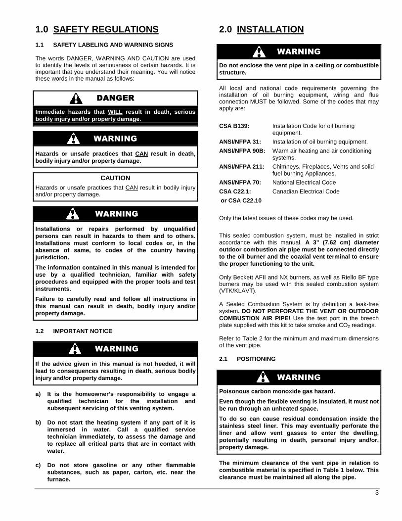
FIGURE 3
8. Silicone seal the circumference of the joint where the stabiliser shroud connects to the main body of the terminal, see Figure 4;
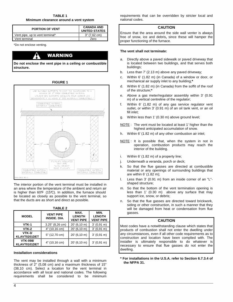
FIGURE 4
Apply caulking to the back plate of the stabiliser shroud and push the terminal firmly back against the wall, making sure the pressure switch (item G) is located at the top, in an horizontal position as shown in Figure 5 ;
FIGURE 5
9. Tighten the clamp on the wall plate (item E) to secure
the terminal in place;
10. While pushing down gently on the top of the stabiliser shroud, install the 3-2" (5,08 cm) stainless steel screws provided with the kit (item D) to secure the back of the shroud to the wall. Do not over tighten the screws or it will distort the stabiliser shroud. The screws will not be necessary on a concrete or block wall as the mortar can provide positive positioning;
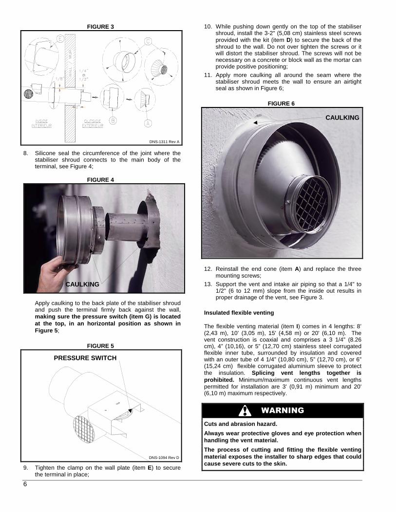
11. Apply more caulking all around the seam where the stabiliser shroud meets the wall to ensure an airtight seal as shown in Figure 6;
FIGURE 6
12. Reinstall the end cone (item A) and replace the three mounting screws;
13. Support the vent and intake air piping so that a 1/4" to 1/2" (6 to 12 mm) slope from the inside out results in proper drainage of the vent, see Figure 3.
Insulated flexible venting
The flexible venting material (item I) comes in 4 lengths: 8’ (2,43 m), 10’ (3,05 m), 15' (4,58 m) or 20' (6,10 m). The vent construction is coaxial and comprises a 3 1/4” (8.26 cm), 4” (10,16), or 5” (12,70 cm) stainless steel corrugated flexible inner tube, surrounded by insulation and covered with an outer tube of 4 1/4” (10,80 cm), 5” (12,70 cm), or 6” (15,24 cm) flexible corrugated aluminium sleeve to protect the insulation. Splicing vent lengths together is prohibited. Minimum/maximum continuous vent lengths permitted for installation are 3' (0,91 m) minimum and 20' (6,10 m) maximum respectively.
WARNING
Cuts and abrasion hazard.
Always wear protective gloves and eye protection wh en handling the vent material.
The process of cutting and fitting the flexible ven ting material exposes the installer to sharp edges that could cause severe cuts to the skin.
CAULKING
PRESSURE SWITCH
DNS-1094 Rev D
CAULKING
DNS-1311 Rev A
7
Connection to the furnace breech VTK-1 and VTK-2
1. Determine the length of the flexible conduit (item I) and cut it as required;
2. Install the flexible conduit in its ultimate position;
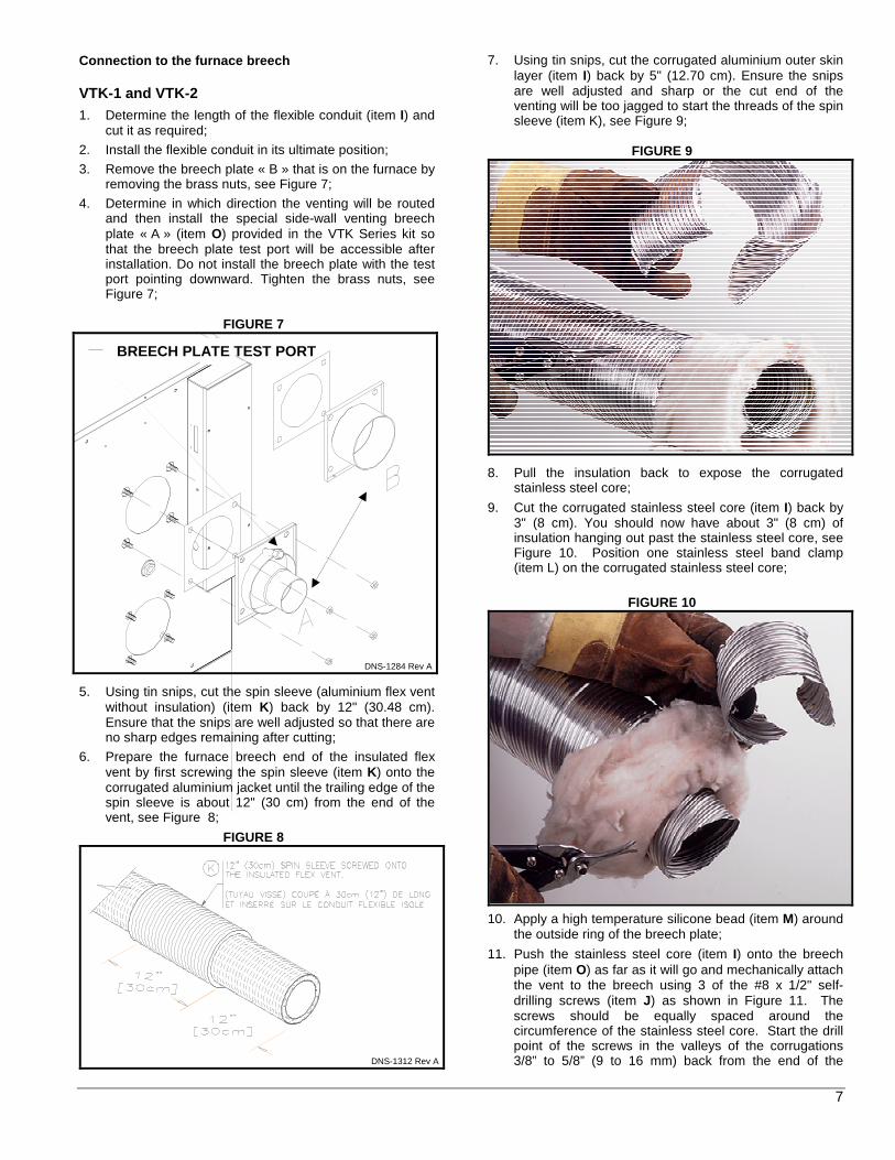
3. Remove the breech plate « B » that is on the furnace by removing the brass nuts, see Figure 7;
4. Determine in which direction the venting will be routed and then install the special side-wall venting breech plate « A » (item O) provided in the VTK Series kit so that the breech plate test port will be accessible after installation. Do not install the breech plate with the test port pointing downward. Tighten the brass nuts, see Figure 7;
FIGURE 7
5. Using tin snips, cut the spin sleeve (aluminium flex vent without insulation) (item K) back by 12" (30.48 cm). Ensure that the snips are well adjusted so that there are no sharp edges remaining after cutting;
6. Prepare the furnace breech end of the insulated flex vent by first screwing the spin sleeve (item K) onto the corrugated aluminium jacket until the trailing edge of the spin sleeve is about 12" (30 cm) from the end of the vent, see Figure 8;
FIGURE 8
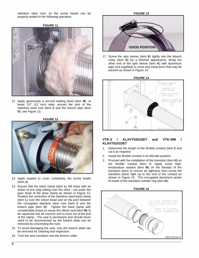
7. Using tin snips, cut the corrugated aluminium outer skin layer (item I) back by 5" (12.70 cm). Ensure the snips are well adjusted and sharp or the cut end of the venting will be too jagged to start the threads of the spin sleeve (item K), see Figure 9;
FIGURE 9
8. Pull the insulation back to expose the corrugated stainless steel core;
9. Cut the corrugated stainless steel core (item I) back by 3" (8 cm). You should now have about 3" (8 cm) of insulation hanging out past the stainless steel core, see Figure 10. Position one stainless steel band clamp (item L) on the corrugated stainless steel core;
FIGURE 10
10. Apply a high temperature silicone bead (item M) around
the outside ring of the breech plate;
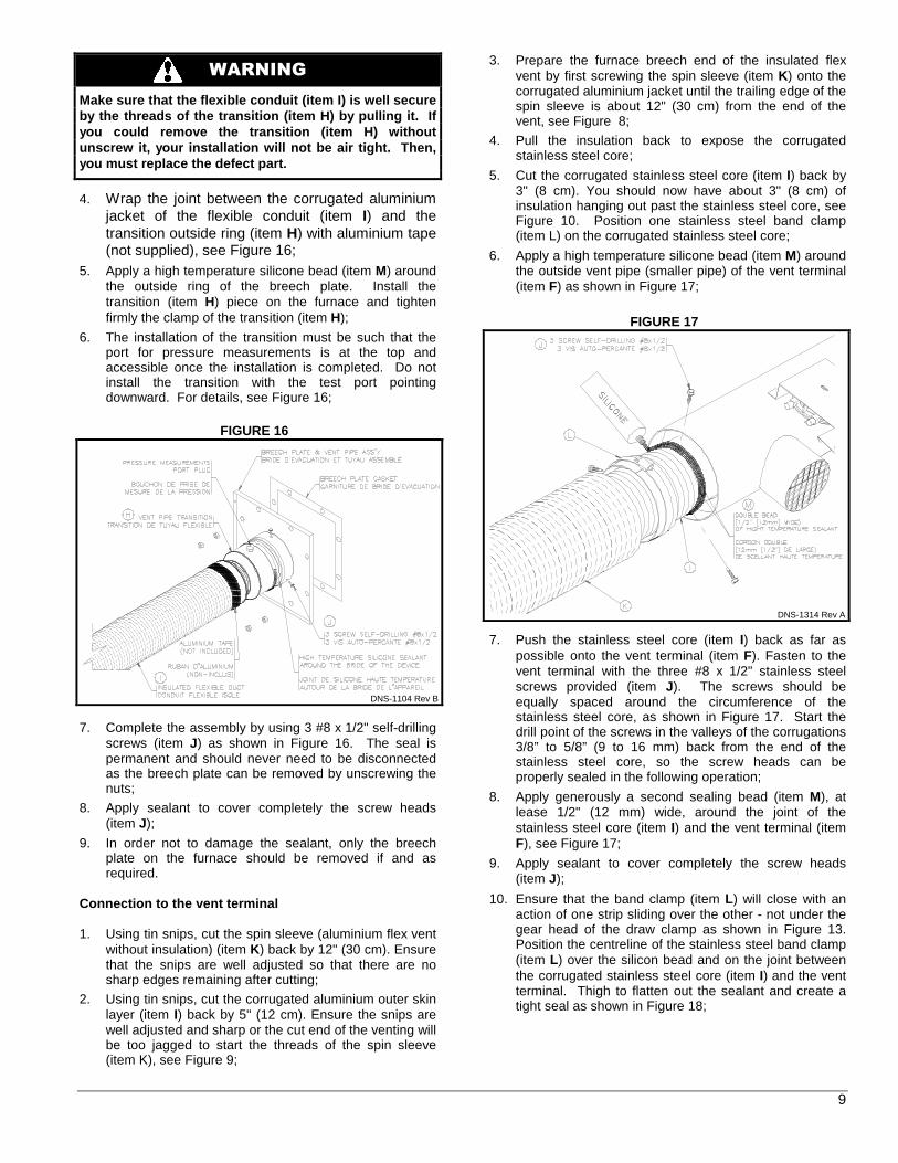
11. Push the stainless steel core (item I) onto the breech pipe (item O) as far as it will go and mechanically attach the vent to the breech using 3 of the #8 x 1/2" self-drilling screws (item J) as shown in Figure 11. The screws should be equally spaced around the circumference of the stainless steel core. Start the drill point of the screws in the valleys of the corrugations 3/8” to 5/8” (9 to 16 mm) back from the end of the
DNS-1284 Rev A
BREECH PLATE TEST PORT
DNS-1312 Rev A
8
stainless steel core, so the screw heads can be properly sealed in the following operation;
FIGURE 11
12. Apply generously a second sealing bead (item M), at lease 1/2" (12 mm) wide, around the joint of the stainless steel core (item I) and the breech pipe (item O), see Figure 12;
FIGURE 12
13. Apply sealant to cover completely the screw heads (item J);
14. Ensure that the band clamp (item L) will close with an action of one strip sliding over the other - not under the gear head of the draw clamp as shown in Figure 13. Position the centreline of the stainless steel band clamp (item L) over the silicon bead and on the joint between the corrugated stainless steel core (item I) and the breech pipe (item O). Tighten the band clamp with considerable torque to cause the silicon seal (item M) to be squeezed into all crevices and to ooze out of the end of the clamp. The seal is permanent and should never need to be disconnected as the breech plate can be removed by unscrewing the nuts;
15. To avoid damaging the seal, only the breech plate can be removed for cleaning and inspection;
16. Tuck the vent insulation into the breech collar;
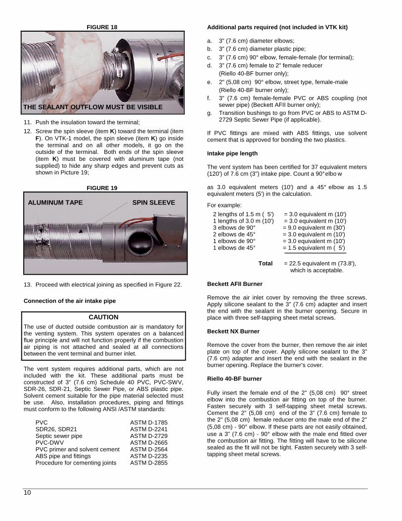
FIGURE 13
17. Screw the spin sleeve (item K) tightly into the breech collar (item O) for a finished appearance. Wrap the other end of the spin sleeve (item K) with aluminium tape (not supplied) to cover any metal burrs that may be present as shown in Figure 14.
FIGURE 14
VTK-3 / KLAVT0201DET and VTK-098 / KLAVT0101DET
1. Determine the length of the flexible conduit (item I) and cut it as required;
2. Install the flexible conduit in its ultimate position;
3. Proceed with the installation of the transition (item H) on the flexible conduit (item I). Apply some high-temperature sealant (item M) on the threads of the transition piece to ensure air tightness then screw the transition piece right up to the end of the conduit as shown in Figure 15. The corrugated aluminium jacket fit inside of the transition outside ring (item H);
FIGURE 15
GOOD POSITION
DNS-1312 Rev A
9
WARNING
Make sure that the flexible conduit (item I) is wel l secure by the threads of the transition (item H) by pullin g it. If you could remove the transition (item H) without unscrew it, your installation will not be air tight . Then, you must replace the defect part.
4. Wrap the joint between the corrugated aluminium jacket of the flexible conduit (item I) and the transition outside ring (item H) with aluminium tape (not supplied), see Figure 16;
5. Apply a high temperature silicone bead (item M) around the outside ring of the breech plate. Install the transition (item H) piece on the furnace and tighten firmly the clamp of the transition (item H);
6. The installation of the transition must be such that the port for pressure measurements is at the top and accessible once the installation is completed. Do not install the transition with the test port pointing downward. For details, see Figure 16;
FIGURE 16
7. Complete the assembly by using 3 #8 x 1/2" self-drilling screws (item J) as shown in Figure 16. The seal is permanent and should never need to be disconnected as the breech plate can be removed by unscrewing the nuts;
8. Apply sealant to cover completely the screw heads (item J);
9. In order not to damage the sealant, only the breech plate on the furnace should be removed if and as required.
Connection to the vent terminal 1. Using tin snips, cut the spin sleeve (aluminium flex vent
without insulation) (item K) back by 12" (30 cm). Ensure that the snips are well adjusted so that there are no sharp edges remaining after cutting;
2. Using tin snips, cut the corrugated aluminium outer skin layer (item I) back by 5" (12 cm). Ensure the snips are well adjusted and sharp or the cut end of the venting will be too jagged to start the threads of the spin sleeve (item K), see Figure 9;
3. Prepare the furnace breech end of the insulated flex vent by first screwing the spin sleeve (item K) onto the corrugated aluminium jacket until the trailing edge of the spin sleeve is about 12" (30 cm) from the end of the vent, see Figure 8;
4. Pull the insulation back to expose the corrugated stainless steel core;
5. Cut the corrugated stainless steel core (item I) back by 3" (8 cm). You should now have about 3" (8 cm) of insulation hanging out past the stainless steel core, see Figure 10. Position one stainless steel band clamp (item L) on the corrugated stainless steel core;
6. Apply a high temperature silicone bead (item M) around the outside vent pipe (smaller pipe) of the vent terminal (item F) as shown in Figure 17;
FIGURE 17
7. Push the stainless steel core (item I) back as far as possible onto the vent terminal (item F). Fasten to the vent terminal with the three #8 x 1/2" stainless steel screws provided (item J). The screws should be equally spaced around the circumference of the stainless steel core, as shown in Figure 17. Start the drill point of the screws in the valleys of the corrugations 3/8” to 5/8” (9 to 16 mm) back from the end of the stainless steel core, so the screw heads can be properly sealed in the following operation;
8. Apply generously a second sealing bead (item M), at lease 1/2" (12 mm) wide, around the joint of the stainless steel core (item I) and the vent terminal (item F), see Figure 17;
9. Apply sealant to cover completely the screw heads (item J);
10. Ensure that the band clamp (item L) will close with an action of one strip sliding over the other - not under the gear head of the draw clamp as shown in Figure 13. Position the centreline of the stainless steel band clamp (item L) over the silicon bead and on the joint between the corrugated stainless steel core (item I) and the vent terminal. Thigh to flatten out the sealant and create a tight seal as shown in Figure 18;
DNS-1104 Rev B
DNS-1314 Rev A
10
FIGURE 18
11. Push the insulation toward the terminal;
12. Screw the spin sleeve (item K) toward the terminal (item F). On VTK-1 model, the spin sleeve (item K) go inside the terminal and on all other models, it go on the outside of the terminal. Both ends of the spin sleeve (item K) must be covered with aluminum tape (not supplied) to hide any sharp edges and prevent cuts as shown in Picture 19;
FIGURE 19
13. Proceed with electrical joining as specified in Figure 22.
Connection of the air intake pipe
CAUTION
The use of ducted outside combustion air is mandatory for the venting system. This system operates on a balanced flue principle and will not function properly if the combustion air piping is not attached and sealed at all connections between the vent terminal and burner inlet.
The vent system requires additional parts, which are not included with the kit. These additional parts must be constructed of 3” (7.6 cm) Schedule 40 PVC, PVC-SWV, SDR-26, SDR-21, Septic Sewer Pipe, or ABS plastic pipe. Solvent cement suitable for the pipe material selected must be use. Also, installation procedures, piping and fittings must conform to the following ANSI /ASTM standards:
PVC ASTM D-1785 SDR26, SDR21 ASTM D-2241 Septic sewer pipe ASTM D-2729 PVC-DWV ASTM D-2665 PVC primer and solvent cement ASTM D-2564 ABS pipe and fittings ASTM D-2235 Procedure for cementing joints ASTM D-2855
Additional parts required (not included in VTK kit) a. 3” (7.6 cm) diameter elbows; b. 3” (7.6 cm) diameter plastic pipe; c. 3” (7.6 cm) 90° elbow, female-female (for terminal); d. 3” (7.6 cm) female to 2" female reducer
(Riello 40-BF burner only); e. 2" (5,08 cm) 90° elbow, street type, female-male
(Riello 40-BF burner only); f. 3” (7.6 cm) female-female PVC or ABS coupling (not
sewer pipe) (Beckett AFII burner only); g. Transition bushings to go from PVC or ABS to ASTM D-
2729 Septic Sewer Pipe (if applicable). If PVC fittings are mixed with ABS fittings, use solvent cement that is approved for bonding the two plastics. Intake pipe length The vent system has been certified for 37 equivalent meters (120') of 7.6 cm (3") intake pipe. Count a 90° elbo w as 3.0 equivalent meters (10') and a 45° elbow as 1 .5 equivalent meters (5') in the calculation.
For example:
2 lengths of 1.5 m ( 5') = 3.0 equivalent m (10') 1 lengths of 3.0 m (10') = 3.0 equivalent m (10') 3 elbows de 90° = 9.0 equivalent m (30') 2 elbows de 45° = 3.0 equivalent m (10') 1 elbows de 90° = 3.0 equivalent m (10') 1 elbows de 45° = 1.5 equivalent m ( 5')
Total = 22.5 equivalent m (73.8'),
which is acceptable. Beckett AFII Burner Remove the air inlet cover by removing the three screws. Apply silicone sealant to the 3” (7.6 cm) adapter and insert the end with the sealant in the burner opening. Secure in place with three self-tapping sheet metal screws. Beckett NX Burner Remove the cover from the burner, then remove the air inlet plate on top of the cover. Apply silicone sealant to the 3” (7.6 cm) adapter and insert the end with the sealant in the burner opening. Replace the burner’s cover. Riello 40-BF burner Fully insert the female end of the 2" (5,08 cm) 90° street elbow into the combustion air fitting on top of the burner. Fasten securely with 3 self-tapping sheet metal screws. Cement the 2" (5,08 cm) end of the 3” (7.6 cm) female to the 2" (5,08 cm) female reducer onto the male end of the 2" (5,08 cm) - 90° elbow. If these parts are not easily obtained, use a 3” (7.6 cm) - 90° elbow with the male end fitted over the combustion air fitting. The fitting will have to be silicone sealed as the fit will not be tight. Fasten securely with 3 self-tapping sheet metal screws.
THE SEALANT OUTFLOW MUST BE VISIBLE
SPIN SLEEVE ALUMINUM TAPE
11
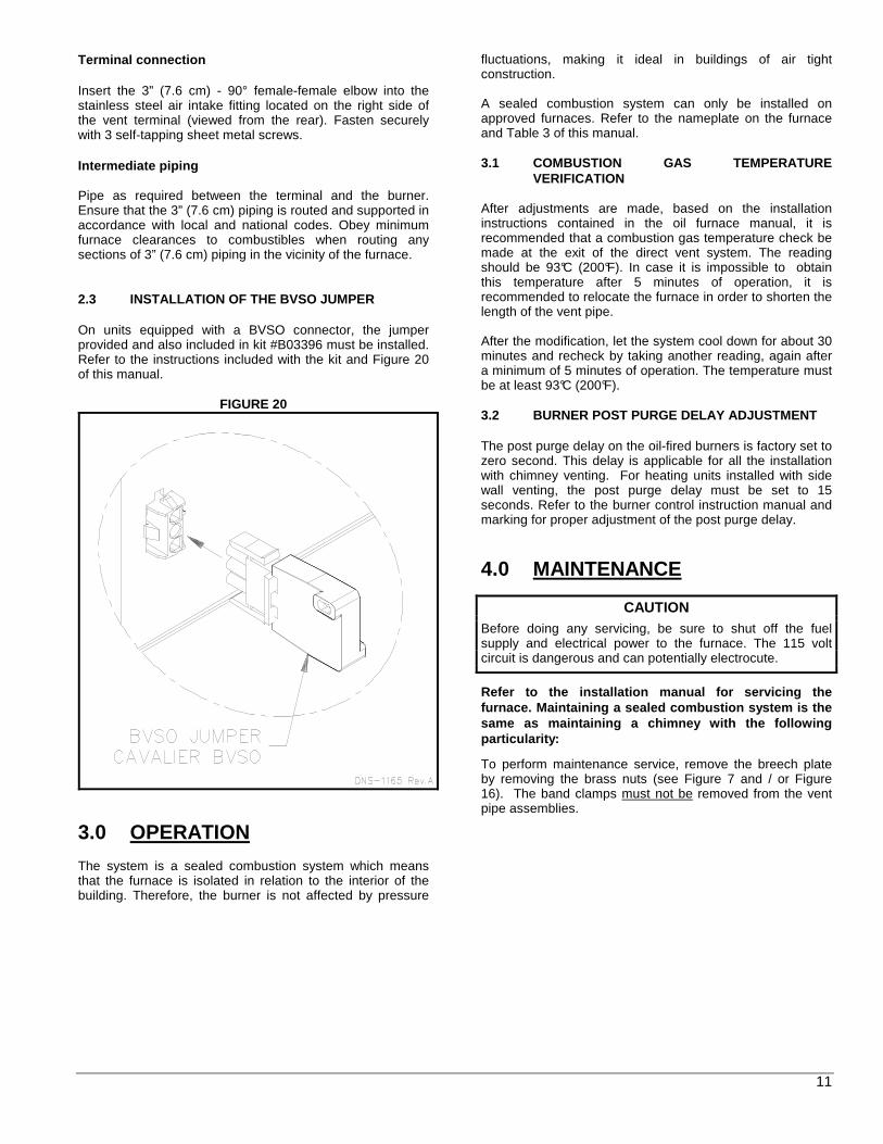
Terminal connection Insert the 3” (7.6 cm) - 90° female-female elbow into the stainless steel air intake fitting located on the right side of the vent terminal (viewed from the rear). Fasten securely with 3 self-tapping sheet metal screws. Intermediate piping Pipe as required between the terminal and the burner. Ensure that the 3” (7.6 cm) piping is routed and supported in accordance with local and national codes. Obey minimum furnace clearances to combustibles when routing any sections of 3” (7.6 cm) piping in the vicinity of the furnace. 2.3 INSTALLATION OF THE BVSO JUMPER On units equipped with a BVSO connector, the jumper provided and also included in kit #B03396 must be installed. Refer to the instructions included with the kit and Figure 20 of this manual.
FIGURE 20
3.0 OPERATION The system is a sealed combustion system which means that the furnace is isolated in relation to the interior of the building. Therefore, the burner is not affected by pressure
fluctuations, making it ideal in buildings of air tight construction. A sealed combustion system can only be installed on approved furnaces. Refer to the nameplate on the furnace and Table 3 of this manual. 3.1 COMBUSTION GAS TEMPERATURE VERIFICATION After adjustments are made, based on the installation instructions contained in the oil furnace manual, it is recommended that a combustion gas temperature check be made at the exit of the direct vent system. The reading should be 93°C (200°F). In case it is impossible to obtain this temperature after 5 minutes of operation, it is recommended to relocate the furnace in order to shorten the length of the vent pipe. After the modification, let the system cool down for about 30 minutes and recheck by taking another reading, again after a minimum of 5 minutes of operation. The temperature must be at least 93°C (200°F). 3.2 BURNER POST PURGE DELAY ADJUSTMENT The post purge delay on the oil-fired burners is factory set to zero second. This delay is applicable for all the installation with chimney venting. For heating units installed with side wall venting, the post purge delay must be set to 15 seconds. Refer to the burner control instruction manual and marking for proper adjustment of the post purge delay.
4.0 MAINTENANCE
CAUTION
Before doing any servicing, be sure to shut off the fuel supply and electrical power to the furnace. The 115 volt circuit is dangerous and can potentially electrocute.
Refer to the installation manual for servicing the furnace. Maintaining a sealed combustion system is the same as maintaining a chimney with the following particularity:
To perform maintenance service, remove the breech plate by removing the brass nuts (see Figure 7 and / or Figure 16). The band clamps must not be removed from the vent pipe assemblies.

12
TABLE 3
Burner Vent Terminal
Beckett Riello Terminal Insulated Flex Vent
AMP098 NX-56LQ R40-BF3 VTK-098 IFV098-10 / IFV098-20
AMP112 NX-56LQ R40-BF5 VTK-098 IFV098-10 / IFV098-20
AMP154 NX-50LC R40-BF5 VTK-3 IFV5-08 / IFV5-20
AMT098 NX-56LQ R40-BF3 VTK-098 IFV098-10 / IFV098-20
AMT112 NX-56LQ R40-BF5 VTK-098 IFV098-10 / IFV098-20
AMT154 NX-50LC R40-BF5 VTK-3 IFV5-08 / IFV5-20
HMT R40-BF5 VTK-3 IFV5-08 / IFV5-20
NOLF105 AFII-85 R40-BF3 VTK-1 IFV3-15 / IFV3-23 / IFV3-30
NOUF105 AFII-85 R40-BF3 VTK-1 IFV3-15 / IFV3-23 / IFV3-30
OBLAAB036098AABE NX-56LQ R40-BF3 KLAVT0101DET KLAFV0101DET / KLAFV0201DET
OBLAAB048112AABF NX-56LQ R40-BF5 KLAVT0101DET KLAFV0101DET / KLAFV0201DET
OBLAAB060154AABG NX-50LC R40-BF5 KLAVT0201DET KLAFV0301DET / KLAFV0401DET
OBMAAB036098AABE NX-56LQ R40-BF3 KLAVT0101DET KLAFV0101DET / KLAFV0201DET
OBMAAB042112AABF NX-56LQ R40-BF5 KLAVT0101DET KLAFV0101DET / KLAFV0201DET
OBMAAB060154AABG NX-50LC R40-BF5 KLAVT0201DET KLAFV0301DET / KLAFV0401DET
OCF105 AFII-85 R40-BF3 VTK-1 IFV3-15 / IFV3-23 / IFV3-30
ODH53F AFII-85 R40-BF3 VTK-1 IFV3-15 / IFV3-23 / IFV3-30
OHB53F AFII-85 R40-BF3 VTK-1 IFV3-15 / IFV3-23 / IFV3-30
OHB64F AFII-150 R40-BF5 VTK-2 IFV4-15 / IFV4-23 / IFV4-30
OLB53F AFII-85 R40-BF3 VTK-1 IFV3-15 / IFV3-23 / IFV3-30
OLB53R AFII-85 R40-BF3 VTK-1 IFV3-15 / IFV3-23 / IFV3-30
OLB64R AFII-150 R40-BF5 VTK-2 IFV4-15 / IFV4-23 / IFV4-30
OLF105 AFII-85 R40-BF3 VTK-1 IFV3-15 / IFV3-23 / IFV3-30
OLR098 / OLV098 NX-56LQ R40-BF3 VTK-098 IFV098-10 / IFV098-20
OLR105 AFII-85 R40-BF3 VTK-1 IFV3-15 / IFV3-23 / IFV3-30
OLR112 / OLV112 NX-56LQ R40-BF5 VTK-098 IFV098-10 / IFV098-20
OLR154 / OLV154 NX-50LC R40-BF5 VTK-3 IFV5-08 / IFV5-20
OLR160 AFII-150 R40-BF5 VTK-2 IFV4-15 / IFV4-23 / IFV4-30
OMF098 / OMV098 NX-56LQ R40-BF3 VTK-098 IFV098-10 / IFV098-20
OMF112 / OMV112 NX-56LQ R40-BF5 VTK-098 IFV098-10 / IFV098-20
OMF154 / OMV154 NX-50LC R40-BF5 VTK-3 IFV5-08 / IFV5-20
OUF105 AFII-85 R40-BF3 VTK-1 IFV3-15 / IFV3-23 / IFV3-30
OUF160 AFII-150 R40-BF5 VTK-2 IFV4-15 / IFV4-23 / IFV4-30
OVLAAB036098AABF NX-56LQ R40-BF3 KLAVT0101DET KLAFV0101DET / KLAFV0201DET
OVLAAB048112AABG NX-56LQ R40-BF5 KLAVT0101DET KLAFV0101DET / KLAFV0201DET
OVLAAB060154AABG NX-50LC R40-BF5 KLAVT0201DET KLAFV0301DET / KLAFV0401DET
OVMAAB036098AABF NX-56LQ R40-BF3 KLAVT0101DET KLAFV0101DET / KLAFV0201DET
OVMAAB042112AABF NX-56LQ R40-BF5 KLAVT0101DET KLAFV0101DET / KLAFV0201DET
OVMAAB060154AABG NX-50LC R40-BF5 KLAVT0201DET KLAFV0301DET / KLAFV0401DET
SCH-105 AFII-85 R40-BF3 VTK-1 IFV3-15 / IFV3-23 / IFV3-30
SCH-160 AFII-150 R40-BF5 VTK-2 IFV4-15 / IFV4-23 / IFV4-30
SCL-105 AFII-85 R40-BF3 VTK-1 IFV3-15 / IFV3-23 / IFV3-30
SCL-160 AFII-150 R40-BF5 VTK-2 IFV4-15 / IFV4-23 / IFV4-30
TMP-105 AFII-85 R40-BF3 VTK-1 IFV3-15 / IFV3-23 / IFV3-30

13
FIGURE 21
FIGURE 22 Wiring Diagram

14
VTK-1VTK-098/
KLAVT0101DETVTK-2
VTK-3/ KLAVT0201DET
A End Cone 4DETECK1 4DETECK1B Stabilizer Shroud 4DETTEK1 4DETTEK3C Self-drilling ScrewsD SS#10x2" TypeA RH ScrewsE Interior Mounting PlateF Vent Terminal VTK-1 VTK-098 VTK-2 VTK-3G Pressure Gauge R99F033 R99F034H Flex Pipe Transition
5" to 4" Z13J0036" to 5" Z13J004
I Insulated Flex Pipe3" Ø x 15' IFV-3-153" Ø x 23' IFV-3-234" Ø x 10' IFV098-10 / KLAFV0101DET
4" Ø x 15' IFV-4-154" Ø x 20' IFV098-20 / KLAFV0201DET
4" Ø x 23' IFV-4-235" Ø x 8' IFV-5-8 / KLAFV0301DET
5" Ø x 20' IFV-5-20 / KLAFV0401DET
J SS#8x1/2" RHMS TEK ScrewsK Spin SleeveL Band Clamp 4DETCBK1 4DETCBK3M SiliconeN BVSO jumper kit
Parts List
Item DescriptionNumber
4DETCBK2
B03396
4DETECK14DETTEK2
R99F032
F10G005
PARTS LIST
DNS-1094 Rev B

Imprimé au Canada Imprimé sur papier 100% recyclé
Attention : Ne pas altérer votre unité ou ses contrôles. Appeler un technicien qualifié.
2011-06-30 X40142 Rév. G
SYSTÈME DE
COMBUSTION SCELLÉE
(ÉVACUATION DIRECTE) Modèles :
VTK-1 VTK-2 VTK-3/ KLAVT0201DET VTK-098/ KLAVT0101DET
Fabriqué par :
Industries Dettson inc. 3400, boulevard Industriel Sherbrooke, Québec - Canada J1L 1V8
INSTALLATEUR / TECHNICIEN : UTILISER LES RENSEIGNEMENTS DANS CE MANUEL POUR L’INSTALLATION ET L’ENTRETIEN DE L’APPAREIL ET GARD ER LE DOCUMENT PRÈS DE L’UNITÉ POUR RÉFÉRENCES ULTÉRIEURE S. PROPRIÉTAIRE : S.V.P. GARDEZ CE MANUEL PRÈS DE L’UNITÉ POUR RÉFÉRE NCES ULTÉRIEURES.
DNS-1074 Rev. A


3
1.0 RÈGLES DE SÉCURITÉ 1.1 SIGNALISATION DANGER, MISE EN GARDE ET
AVERTISSEMENT Comprenez bien la portée des mots suivants : DANGER, MISE EN GARDE et AVERTISSEMENT. Ces mots sont associés aux symboles de sécurité. Vous les retrouverez dans le manuel de la façon suivante :
DANGER
Le mot DANGER indique les plus graves dangers, ceux qui provoqueront la mort ou des dommages corporels et/ou matériels sérieux.
MISE EN GARDE
L’expression MISE EN GARDE signifie un danger qui peut entraîner la mort ou des dommages corporels et/ou matériels.
AVERTISSEMENT
Quant au mot AVERTISSEMENT, il est utilisé pour indiquer les pratiques dangereuses qui peuvent provoquer des dommages corporels et/ou matériels mineurs.
MISE EN GARDE
L’installation ou les réparations par du personnel non qualifié peuvent entraîner des risques pour vous et à autrui. L’installation DOIT être conforme aux codes locaux ou, dans le cas d’absence de codes locaux, e lle doit être conforme aux codes nationaux qui s’appliquent.
Les renseignements contenus dans ce manuel s’adressent à un technicien qualifié, expérimenté d ans ce type de travail, au courant des précautions à pr endre, des règles de sécurité à respecter et muni des outi ls appropriés ainsi que des instruments de vérificatio n adéquats.
Si les instructions de ce manuel ne sont pas soigneusement suivies, cela peut causer un mauvais fonctionnement de la fournaise, entraîner la mort o u des dommages corporels et/ou matériels.
1.2 REMARQUES IMPORTANTES
MISE EN GARDE
Si les conseils dans ce manuel ne sont pas respecté s, les conséquences provoqueront la mort ou des dommages corporels et/ou matériels sérieux.
a) Il est de la responsabilité et de l’obligation d u propriétaire d’engager un technicien qualifié pour l’installation et le service subséquent du système d'évacuation.
b) Ne pas faire fonctionner le système de chauffage s'il est immergé dans l’eau. Appelez immédiatement un technicien qualifié pour vérifier les dommages et remplacer les pièces critiques qui ont été en conta ct avec l’eau.
c) Ne pas ranger ou utiliser d’essence ou toutes au tres
substances inflammables à proximité de l’appareil, ni d’autres matières combustibles tel que le papier, l e carton, etc.
2.0 INSTALLATION
MISE EN GARDE
Ne pas enfermer le tuyau d’évent dans un plafond ou à l’intérieur d’une structure combustible.
Toutes les exigences requises par les codes locaux et nationaux concernant l’installation d’équipement de chauffage au mazout, les installations électriques et les raccordements de conduits doivent être respectées. Certains codes (émis par l’Institut des standards canadiens) qui pourraient s’appliquer sont :
CSA B139 : Code d’installation d’équipements de chauffage au mazout
ANSI/NFPA 31 : Installation d’équipement de chauffage au mazout
ANSI/NFPA 90B : Systèmes de chauffage à air chaud et systèmes d’air climatisé
ANSI/NFPA 211 : Cheminées, foyers, évents et appareils de chauffage
ANSI/NFPA 70 : Code national d’électricité
CSA C22.1 : Code canadien d’électricité ou CSA C22.10 Seule l’édition la plus récente des codes doit être utilisée. Ce système de combustion scellé doit être installé selon les instructions contenues dans ce manuel. Pour un fonctionnement adéquat, le tuyau d’alimentation en air de 7.62 cm (3") de diamètre, doit obligatoirement être raccordé au brûleur au mazout et à l’évacuateur mur al coaxial. Seuls les brûleurs Beckett modèles NX et AFII, ainsi que les brûleurs Riello de type BF peuvent être utilisés avec ce système de combustion scellé (VTK/KLAVT). Le système de combustion scellé est par définition un système sans fuite. NE FAIRE AUCUNE PERFORATION DANS LE TUYAU D’ÉVACUATION OU LE TUYAU D’ALIMENTATION EN AIR. Utiliser l’ouverture sur l’adaptateur fourni avec le système d’évacuation pour effectuer le test de fumée et le test de CO2. Se référer au tableau 2 pour les dimensions minimum et maximum du conduit d’évacuation.

4
2.1 EMPLACEMENT
MISE EN GARDE
Risque d’empoisonnement par monoxyde de carbone.
Même si le conduit flexible est isolé, il ne peut p asser dans un espace non isolé (pas chauffé).
Ceci causerait de la condensation résiduelle qui pe ut, à long terme, perforer le conduit en acier inoxydable .
Le dégagement minimum du tuyau d’évacuation par rapport aux matériaux combustibles requis est spéci fié au tableau 1. S’assurer que ces dégagements sont respectés sur toute la longueur du tuyau.
TABLEAU 1 Dégagements minimums autour du système d’évacuation mural
*Le conduit ne doit pas passer dans un enceinte fermé.
MISE EN GARDE
Ne pas enfermer le tuyau d’évent dans un plafond ou à l’intérieur d’une structure combustible.
FIGURE 1
La partie intérieure de l’évacuateur mural doit être installée dans un endroit où la température de l’air ambiant et de l’air de retour est supérieure à 15°C (60°F). De plus, l’ unité devrait être située aussi près que possible de l’évacuateur de façon à maintenir les raccordements courts et directs.
TABLEAU 2
MODÈLE DIA. INT. TUYAU
D’ÉVACUATION
LONG. MAX. ÉVAC.
LONG. MIN.
ÉVAC.
VTK-1 8,26 cm (3.25") 6,10 m (20') ,91 m (3') VTK-2 10,16 cm (4") 6,10 m (20') ,91 m (3') VTK-3/
KLAVT0201DET 12,70 cm (5") 6,10 m (20') ,91 m (3')
VTK-098/ KLAVT0101DET
10,16 cm (4") 6,10 m (20') ,91 m (3')
Considérations concernant l’installation L’évacuateur mural peut être installé à travers un mur d’une épaisseur maximum de 38,10 cm (15") ou une épaisseur minimum de 5,08 cm (2"). Sélectionner l’emplacement de la sortie de l’évacuateur mural en respectant les codes locaux et nationaux. Les exigences suivantes doivent être considérées comme minimales et peuvent être remplacées par un code local ou national plus strict.
AVERTISSEMENT Enlevez la neige, la glace ou tout autre débris autour de l’évacuateur mural. Ceux-ci peuvent nuire au bon fonctionnement de l’appareil.
Un évent ne doit pas se terminer : a. Directement au-dessus d’un trottoir ou d’une entrée
pavée, situé entre deux bâtiments et desservant ces deux bâtiments ;
b. À moins de 2,13 m (7’) au-dessus de toute entrée pavée ;
c. À moins de 1,82 m (6’) (au Canada)* d’une porte ou d’une fenêtre qui s’ouvre, ou d’une ouverture destinée à l’approvisionnement en air d’un édifice ;
d. À moins de 1,82 m (6’) (au Canada)* du parement de sous-face du toit de la structure ;
e. Au dessus d’un compteur de gaz, ou d’un régulateur, ou à moins de 0,91 m (3’) du centre vertical du régulateur ;
f. À moins de 1,82 m (6’) de toute sortie d’évent d’un régulateur de gaz, ou à moins de 0,91 m (3’) de l’évent d’un réservoir de mazout, ou de l’entrée pour le remplissage du mazout ;
g. À moins de 0,30 m (1’) au-dessus du niveau du sol ;
NOTE : L'évent doit être localisé à au moins 1' au-dessus du niveau anticipé de neige.
h. À 1,82 m (6’) de toute entrée d’air pour la combustion ;
NOTE : Lorsque le système est à l'arrêt, il est possible que des produits de combustion atteignent l'intérieur du bâtiment.
i. À moins de 1,82 m (6’) de la limite du terrain ;
j. Sous une véranda, un porche ou un patio ;
k. Avec les gaz de combustion dirigés vers des matériaux combustibles, ou vers toute ouverture des édifices avoisinants, situés à moins de 1,82 m (6’) ;
l. À moins de 0,91 m (3’) du coin intérieur d’une structure en "L" ;
SECTION DU CONDUIT D’ÉVACUATION CANADA et
ÉTATS-UNIS Conduit d’évacuation, jusqu’à l’évacuateur mural* 7,62 cm (3") Évacuateur mural ZÉRO

5
FIGURE 2
m. Avec le dessous de l’ouverture de l’extrémité de l’évent située à moins 0,30 m (1’) au-dessus de toutes surfaces pouvant porter de la glace, de la neige, ou des débris ;
n. Avec les gaz de combustion dirigés vers de la maçonnerie de brique, un recouvrement, ou autre construction qui pourrait être endommagée par la chaleur, ou la condensation des gaz de combustion.
AVERTISSEMENT
La majorité des codes ont une clause mère énonçant que les produits de combustion ne doivent pénétrer dans l’habitation sous aucunes circonstances et ce, même si toutes les autres exigences du code concernant la construction et l’emplacement ont été respectées. L’installateur a la responsabilité ultime de prendre toutes les mesures nécessaires pour s’assurer que les produits de combustion ne peuvent pas s’introduire dans les espaces habités.
* Pour installation aux États-Unis, consulter la Se ction 6.7.3.4 de la norme NFPA 31.
2.2 INSTALLATION DES COMPOSANTES Se référer à la figure 2 pour plus de détail sur l’identification des composantes. Installation de l’évacuateur au mur 1. Faire un trou de 15,24 cm (6") de diamètre pour les
terminaux VTK-098/KLAVT0101DET, VTK-1 et VTK-2 et un trou de 15,88 cm (6¼") de diamètre pour le VTK-3/KLAVT0201DET dans le mur en considérant les restrictions énumérés dans la section précédente (2.1) ;
2. Fixer la plaque murale sur le mur intérieur avec des vis appropriées, fournies par l’installateur. Prendre note que le support du détecteur de pression (item G) doit être enlevé pour atteindre la vis supérieure droite de la

6
plaque murale (item E). Installer la plaque murale pour que la partie supérieure du trou dans la plaque soit à 3,18 mm (1/8") de la partie supérieure du trou dans le mur, voir la figure 3. Ceci assurera l’inclinaison requise de l’évacuateur de l’intérieur vers l’extérieur ;
FIGURE 3
3. Enlever les 3 vis (item C) qui fixent le cône de l’évacuateur (item A) et l’enlever ;
4. Enlever les 4 vis (item C) qui fixent le stabilisateur de l’évacuateur (item B) et l’enlever ;
5. Passer la partie principale de l’évacuateur (de l'intérieur à l'extérieur) à travers le mur, et la laisser dépasser de 5,08 cm (2") du coté extérieur, voir la figure 3 ;
6. Installer le stabilisateur de l’évacuateur (item B), tel que démontré à la figure 4 et remettre les 4 vis;
FIGURE 4
7. Pour les murs de ciment, il est possible que le stabilisateur ne couvre pas toutes les irrégularités du trou dans le mur. Il est possible d’installer une plaque murale en acier inoxydable (304, 316 ou 316L) fournie par l’installateur ;
8. Appliquer un scellant (silicone) à l’endroit où le stabilisateur rencontre la partie principale de l’évacuateur (tuyau), voir la figure 4 ;
9. Appliquer un scellant adhésif sur la partie arrière du stabilisateur et pousser fermement le stabilisateur contre le mur. S’assurer que le détecteur de pression
(item G) est situé sur le dessus, en position horizontale comme montré à la figure 5 ;
FIGURE 5
10. Serrer le collet de la plaque murale intérieure (item E) pour fixer le tout en place ;
11. Avec les 3 vis en acier inoxydable de 5,08 cm (2") fournies (item D), fixer le tout en place, en poussant vers le bas pour assurer l’inclinaison requise. Ne pas trop serrer les vis pour ne pas déformer le stabilisateur. Les vis ne sont pas requises pour les murs de ciment ;
12. Appliquer suffisamment de scellant autour du stabilisateur pour avoir un joint étanche tel que démontré à la figure 6 ;
FIGURE 6
13. Réinstaller le cône (item A) avec les 3 vis ;
14. L’inclinaison de l’évacuateur doit être de 6 à 12 mm (1/4" à 1/2"), de l’intérieur vers l’extérieur, afin que le drainage dans l’évacuateur soit efficace, voir la figure 3.
SCELLANT
DÉTECTEUR DE PRESSION
DNS-1094 Rév D
SCELLANT
DNS-1311 Rév A
7
Installation des conduits flexibles isolés Les conduits flexibles (item I) sont disponibles en 4 longueurs : 2,43 m (8’), 3,05 m (10’), 4,58 m (15'), 6,10 m (20') ou 7,15 m. La construction du conduit est de type coaxial et comprend un tuyau flexible intérieur en acier inoxydable de 8.26 cm (3 1/4"), 10,16 cm (4"), ou 12,70 cm (5)" de diamètre entouré d’une isolation qui est elle-même entourée du tuyau flexible extérieur en aluminium de 10,80 cm (4 1/4"), 12,70 cm (5"), ou 15,24 cm (6") de diamètre. Il est interdit de joindre deux bouts de conduit. Les longueurs minimum et maximum pour ces installations sont, respectivement, de 0,91 m (3’) minimum et de 6,10 m (20’) maximum.
MISE EN GARDE
Danger de coupures.
Toujours porter des gants et des lunettes protectri ces lors de l’installation.
Couper le conduit flexible peut laisser des parties coupantes sur le tuyau et celles-ci peuvent blesser l’installateur qui n’y porte pas attention.
Branchement à la sortie de la fournaise VTK-1 et VTK-2
1. Déterminer la longueur de conduit flexible (item I) requise, et couper le au besoin ;
2. Installer le conduit flexible dans sa position finale ;
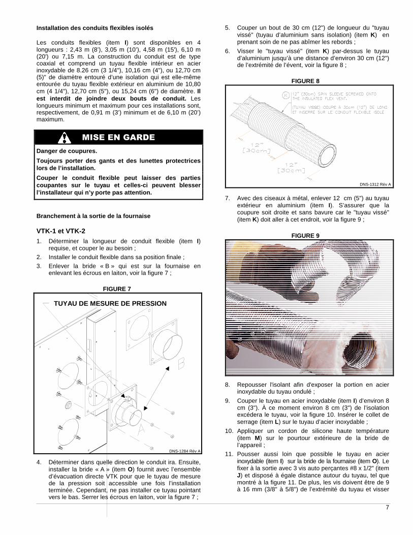
3. Enlever la bride « B » qui est sur la fournaise en enlevant les écrous en laiton, voir la figure 7 ;
FIGURE 7
4. Déterminer dans quelle direction le conduit ira. Ensuite, installer la bride « A » (item O) fournit avec l’ensemble d’évacuation directe VTK pour que le tuyau de mesure de la pression soit accessible une fois l’installation terminée. Cependant, ne pas installer ce tuyau pointant vers le bas. Serrer les écrous en laiton, voir la figure 7 ;
5. Couper un bout de 30 cm (12") de longueur du "tuyau vissé" (tuyau d’aluminium sans isolation) (item K) en prenant soin de ne pas abîmer les rebords ;
6. Visser le "tuyau vissé" (item K) par-dessus le tuyau d’aluminium jusqu’à une distance d’environ 30 cm (12") de l’extrémité de l’évent, voir la figure 8 ;
FIGURE 8
7. Avec des ciseaux à métal, enlever 12 cm (5") au tuyau extérieur en aluminium (item I). S’assurer que la coupure soit droite et sans bavure car le "tuyau vissé" (item K) doit aller à cet endroit, voir la figure 9 ;
FIGURE 9
8. Repousser l'isolant afin d'exposer la portion en acier inoxydable du tuyau ondulé ;
9. Couper le tuyau en acier inoxydable (item I) d’environ 8 cm (3"). À ce moment environ 8 cm (3") de l’isolation excédera le tuyau, voir la figure 10. Insérer le collet de serrage (item L) sur le tuyau d’acier inoxydable ;
10. Appliquer un cordon de silicone haute température (item M) sur le pourtour extérieure de la bride de l’appareil ;
11. Pousser aussi loin que possible le tuyau en acier inoxydable (item I) sur la bride de la fournaise (item O). Le fixer à la sortie avec 3 vis auto perçantes #8 x 1/2" (item J) et disposé à égale distance autour du tuyau, tel que montré à la figure 11. De plus, les vis doivent être de 9 à 16 mm (3/8" à 5/8") de l’extrémité du tuyau et visser
DNS-1284 Rév A
TUYAU DE MESURE DE PRESSION
DNS-1312 Rév A

8
dans un creux du tuyau. Ceci assurera une étanchéité parfaite lors des prochaines opérations ;
FIGURE 10
12. Appliquer généreusement un deuxième cordon de scellant (item M) d’au moins 13 mm (1/2’’) de large sur le joint entre le tuyau en acier inoxydable (item I) et sur la bride de la fournaise (item O), voir la figure 12 ;
FIGURE 11
13. Recouvrir les têtes de vis auto perçantes de l’étape précédente avec le scellant (item J) ;
14. Vérifier que le collet en acier inoxydable (item L) est bien dans la bonne position pour un serrage adéquat comme montré à la figure 13. Positionner le centre du collet (item L) sur le cordon de silicone (item M), donc sur le joint entre le tuyau en acier inoxydable (item I) et la bride de la fournaise (item O) et serrer suffisamment pour qu’il s’écrase. Ce joint est permanent et le nettoyage de l’échangeur devra dorénavant se faire en enlevant les quatre écrous qui fixent la bride (item O) à l’appareil ;
FIGURE 12
15. Afin de ne pas endommager le scellant, seulement la bride de l'appareil devrait être retirée au besoin ;
FIGURE 13
16. Pousser l’isolation vers la bride.
17. Déplacer le "tuyau vissé" (item K) vers la bride (item O) le plus loin possible. L’autre extrémité du "tuyau vissé" (item K) doit être caché avec du ruban d’aluminium (non fourni) pour enlever les bavures et éviter les coupures comme montrées à la figure 14.
FIGURE 14
VTK-3 / KLAVT0201DET et VTK-098 / KLAVT0101DET
1. Déterminer la longueur de conduit flexible (item I) requise, et couper le au besoin ;
2. Installer le conduit flexible dans sa position finale ;
3. Procéder à l’installation de la transition (item H) sur le conduit flexible (item I). Appliquer un joint de silicone haute température (item M) sur les filets de la transition
BONNE POSITION

9
afin de vous assurer d’une bonne étanchéité et visser la transition sur le conduit jusqu’au bout comme montré à la figure 15. La gaine extérieure en aluminium devrait se loger à l’intérieur du collet de la transition (item H) ;
FIGURE 15
MISE EN GARDE
Assurez-vous que le conduit flexible (item I) est b ien retenu par le filet de la transition (item H) en ti rant dessus. Si vous êtes en mesure de retirer la trans ition (item H) sans la dévisser, votre assemblage ne sera pas étanche. Vous devez remplacer la pièce défectueuse .
4. Mettre du ruban d’aluminium (non fourni) sur le joint entre la gaine extérieure en aluminium du conduit flexible (item I) et du collet de la transition (item H), voir la figure 16 ;
5. Appliquer un cordon de silicone haute température (item M) sur le pourtour extérieure de la bride de l’appareil. Fixer la transition (item H) sur la bride de l’appareil et serrer fermement le collet de la transition (item H) ;
6. La transition doit être installée de sorte que le bouchon de prise de mesure de la pression, soit accessible une fois l’installation terminée. Cependant, ne pas installer cette ouverture pointant vers le bas. Se référer à la figure 16 pour les détails ;
FIGURE 16
7. Compléter l’assemblage en ajoutant les 3 vis auto perçantes #8 x 1/2" (item J), tel que montré à la figure
16. Ce joint est permanent et le nettoyage de l’échangeur devra dorénavant se faire en enlevant les écrous qui fixent la bride d’évacuation de l’appareil de chauffage ;
8. Recouvrir les têtes de vis auto perçantes de l’étape précédente avec le scellant (item J) ;
9. Afin de ne pas endommager le scellant, seulement la bride de l'appareil devrait être retirée au besoin.
Branchement à l’évacuateur mural 1. Couper un bout de 30 cm (12") de longueur du "tuyau
vissé" (tuyau d’aluminium sans isolation) (item K) en prenant soin de ne pas abîmer les rebords ;
2. Avec des ciseaux à métal, enlever 12 cm (5") au tuyau extérieur en aluminium (item I). S’assurer que la coupure soit droite et sans bavure car le "tuyau vissé" (item K) doit aller à cet endroit, voir la figure 9;
3. Visser le "tuyau vissé" (item K) par-dessus le tuyau d’aluminium jusqu’à une distance d’environ 30 cm (12") de l’extrémité de l’évent, voir la figure 8 ;
4. Repousser l'isolant afin d'exposer la portion en acier inoxydable du tuyau ondulé ;
5. Couper le tuyau en acier inoxydable (item I) d’environ 8 cm (3"). À ce moment environ 8 cm (3") de l’isolation excédera le tuyau, voir la figure 10. Insérer le collet de serrage (item L) sur le tuyau d’acier inoxydable ;
6. Appliquer un cordon de silicone haute température (item M) sur le pourtour extérieure du tuyau d’évacuation (plus petit tuyau) du terminal d’évacuation (item F) tel que montré à la figure 17 ;
FIGURE 17
7. Pousser aussi loin que possible le tuyau en acier inoxydable (item I) sur le terminal d’évacuation (item F). Le fixer en place avec 3 vis auto perçantes #8 x 1/2" (item J) disposées à égale distance autour du tuyau , tel que montré à la figure 17. De plus, les vis doivent être de 9 à 16 mm (3/8" à 5/8") de l’extrémité du tuyau et visser dans un creux du tuyau. Ceci assurera une étanchéité parfaite lors des prochaines opérations ;
8. Appliquer généreusement un deuxième cordon de scellant (item M) d’au moins 13 mm (1/2’’) de large sur le joint entre le tuyau en acier inoxydable (item I) et le terminale d’évacuation (item F), voir la figure 17 ;
DNS-1312 Rév A
DNS-1104 Rév B
DNS-1314 Rév A

10
9. Recouvrir les têtes de vis auto perçantes de l’étape précédente avec le scellant (item J) ;
10. Vérifier que le collet en acier inoxydable (item L) est bien dans la bonne position pour un serrage adéquat comme montré à la figure 13. Positionner le centre du collet (item L) sur le cordon de silicone (item M), donc sur le joint entre le tuyau en acier inoxydable (item I) et le terminale d’évacuation. Serrer suffisamment pour qu’il s’écrase tel que démontré à la figure 18 ;
FIGURE 18
11. Pousser l’isolation vers le terminal ;
12. Déplacer le "tuyau vissé" (item K) vers le terminal (item F) le plus loin possible. Sur le modèle VTK-1, le "tuyau vissé" (item K) se loge à l’intérieur du terminal, alors que sur tous les autres modèles, il se loge à l’extérieur du terminal. Les deux extrémités du "tuyau vissé" (item K) doivent être caché avec du ruban d’aluminium (non fourni) pour enlever les bavures et éviter les coupures comme montrées à la figure 19 ;
FIGURE 19
13. Procéder au raccordement électrique tel que spécifié à la figure 22.
Branchement du tuyau d’entrée d’air
AVERTISSEMENT
L’utilisation de l’air de combustion acheminé de l’extérieur est obligatoire avec les installations à évacuation murale. Ce système fonctionne selon le principe de la combustion scellée et il ne fonctionnera pas adéquatement si un conduit acheminant l’air de l’extérieur n’est pas connecté directement au brûleur de l’appareil.
Le système d’évacuation requière des pièces additionnelles qui ne sont pas incluses dans l’ensemble. Elles doivent être de 7.6 cm (3") de diamètre et constituées d’un des
matériaux suivant : PVC, PVC-SWV, SDR-26, SDR-21, ABS ou tuyau de fosse septique. Un ciment colle adéquat pour le type de tuyau choisi doit être utilisé. De plus, les procédures d’installation, les conduits et les raccords doivent être conformes aux normes ANSI/ASTM suivantes :
PVC ASTM D-1785 SDR26, SDR21 ASTM D-2241 Tuyau de fosse septique ASTM D-2729 PVC-DWV ASTM D-2665 Adhésif PVC ASTM D-2564 ABS tuyau et raccord ASTM D-2235 Procédure de collage des joints ASTM D-2855
Autres pièces requises (pas incluses dans l’ensembl e VTK) a. Coudes de 7.6 cm (3") de diamètre ;
b. Tuyau de 7.6 cm (3") de diamètre ;
c. Coude 90° de 7.6 cm (3") (femelle-femelle) pour l’évacuateur ;
d. Réducteur 7.6 cm (3") femelle à 5,08 cm (2") femelle (brûleur Riello BF seulement) ;
e. Coude 90° de 5,08 cm (2") de diamètre « street type » femelle-mâle (brûleur Riello BF seulement) ;
f. Adaptateur 7.6 cm (3") femelle-femelle en PVC ou ABS (conduit de fosse septique exclu) (brûleur Beckett AFII-85 seulement) ;
g. Deux raccords de transition entre l’ABS ou PVC et le tuyau fosse septique ASTM D-2729 (si applicable).
Si le PVC est utilisé avec l’ABS, utiliser un ciment colle qui est approuvé pour les deux types de plastique. Longueur de conduit Le système d’évacuation mural a été approuvé pour être utilisé avec une longueur équivalente maximum de 37 m (120') de conduit, 7.6 cm (3") de diamètre. Un coude de 90° est équivalant à une longueur de 3.0m (10') et un coude de 45° à une longueur de 1.5 m (5').
Par exemple :
2 longueurs de 1.5 m (5') = 3.0 m (10') équivalents 1 longueurs de 3.0 m (10') = 3.0 m (10') équivalents 3 coudes de 90° = 9.0 m (30') équivalents
2 coudes de 45° = 3.0 m (10') équivalents 1 coude de 90° = 3.0 m (10') équivalents 1 coude de 45° = 1.5 m ( 5') équivalents
Total = 22.5 m (73.8') équivalents, ce qui est acceptable.
Brûleur Beckett AFII Enlever le couvert de l’entrée d’air du brûleur en enlevant les 3 vis qui le tiennent en place. Appliquer du scellant (silicone) sur un adapteur de 7.6 cm (3") et insérer la partie avec le scellant dans l’ouverture du brûleur. Solidifier avec 3 vis à métal auto perçantes. Brûleur Beckett NX Enlever le couvercle du brûleur, et retirer la plaque permettant l’entrée d’air sur le dessus du couvercle. Appliquer du scellant (silicone) sur un adapteur de 7.6 cm
LE SURPLUS DE SCELLANT DOIT ÊTRE VISIBLE
‘’TUYAU VISSÉ’’ RUBAN D’ALUMINIUM
11
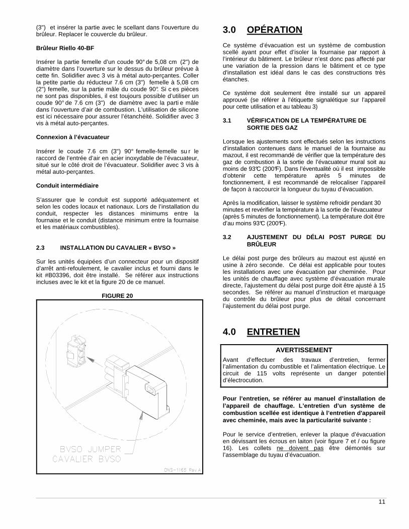
(3") et insérer la partie avec le scellant dans l’ouverture du brûleur. Replacer le couvercle du brûleur. Brûleur Riello 40-BF Insérer la partie femelle d’un coude 90° de 5,08 cm (2") de diamètre dans l’ouverture sur le dessus du brûleur prévue à cette fin. Solidifier avec 3 vis à métal auto-perçantes. Coller la petite partie du réducteur 7.6 cm (3") femelle à 5,08 cm (2") femelle, sur la partie mâle du coude 90°. Si c es pièces ne sont pas disponibles, il est toujours possible d’utiliser un coude 90° de 7.6 cm (3") de diamètre avec la parti e mâle dans l’ouverture d’air de combustion. L’utilisation de silicone est ici nécessaire pour assurer l’étanchéité. Solidifier avec 3 vis à métal auto-perçantes. Connexion à l’évacuateur Insérer le coude 7.6 cm (3") 90° femelle-femelle su r le raccord de l’entrée d’air en acier inoxydable de l’évacuateur, situé sur le côté droit de l’évacuateur. Solidifier avec 3 vis à métal auto-perçantes. Conduit intermédiaire S’assurer que le conduit est supporté adéquatement et selon les codes locaux et nationaux. Lors de l’installation du conduit, respecter les distances minimums entre la fournaise et le conduit (distance minimum entre la fournaise et les matériaux combustibles). 2.3 INSTALLATION DU CAVALIER « BVSO » Sur les unités équipées d’un connecteur pour un dispositif d’arrêt anti-refoulement, le cavalier inclus et fourni dans le kit #B03396, doit être installé. Se référer aux instructions incluses avec le kit et la figure 20 de ce manuel.
FIGURE 20
3.0 OPÉRATION Ce système d’évacuation est un système de combustion scellé ayant pour effet d’isoler la fournaise par rapport à l’intérieur du bâtiment. Le brûleur n’est donc pas affecté par une variation de la pression dans le bâtiment et ce type d'installation est idéal dans le cas des constructions très étanches. Ce système doit seulement être installé sur un appareil approuvé (se référer à l’étiquette signalétique sur l’appareil pour cette utilisation et au tableau 3) 3.1 VÉRIFICATION DE LA TEMPÉRATURE DE SORTIE DES GAZ Lorsque les ajustements sont effectués selon les instructions d’installation contenues dans le manuel de la fournaise au mazout, il est recommandé de vérifier que la température des gaz de combustion à la sortie de l’évacuateur mural soit au moins de 93°C (200°F). Dans l’éventualité où il est impossible d’obtenir cette température après 5 minutes de fonctionnement, il est recommandé de relocaliser l’appareil de façon à raccourcir la longueur du tuyau d’évacuation. Après la modification, laisser le système refroidir pendant 30 minutes et revérifier la température à la sortie de l’évacuateur (après 5 minutes de fonctionnement). La température doit être d’au moins 93°C (200°F). 3.2 AJUSTEMENT DU DÉLAI POST PURGE DU BRÛLEUR Le délai post purge des brûleurs au mazout est ajusté en usine à zéro seconde. Ce délai est applicable pour toutes les installations avec une évacuation par cheminée. Pour les unités de chauffage avec système d’évacuation murale directe, l’ajustement du délai post purge doit être ajusté à 15 secondes. Se référer au manuel d’instruction et marquage du contrôle du brûleur pour plus de détail concernant l’ajustement du délai post purge.
4.0 ENTRETIEN
AVERTISSEMENT
Avant d’effectuer des travaux d’entretien, fermer l’alimentation du combustible et l’alimentation électrique. Le circuit de 115 volts représente un danger potentiel d’électrocution.
Pour l’entretien, se référer au manuel d’installati on de l’appareil de chauffage. L’entretien d’un système d e combustion scellée est identique à l’entretien d'ap pareil avec cheminée, mais avec la particularité suivante : Pour le service d’entretien, enlever la plaque d’évacuation en dévissant les écrous en laiton (voir figure 7 et / ou figure 16). Les collets ne doivent pas être démontés sur l’assemblage du tuyau d’évacuation.
12
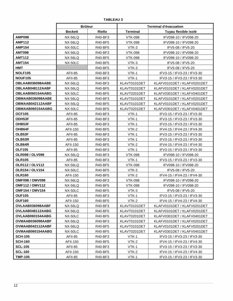
TABLEAU 3
Brûleur Terminal d'évacuation
Beckett Riello Terminal Tuyau flexible isolé
AMP098 NX-56LQ R40-BF3 VTK-098 IFV098-10 / IFV098-20
AMP112 NX-56LQ R40-BF5 VTK-098 IFV098-10 / IFV098-20
AMP154 NX-50LC R40-BF5 VTK-3 IFV5-08 / IFV5-20
AMT098 NX-56LQ R40-BF3 VTK-098 IFV098-10 / IFV098-20
AMT112 NX-56LQ R40-BF5 VTK-098 IFV098-10 / IFV098-20
AMT154 NX-50LC R40-BF5 VTK-3 IFV5-08 / IFV5-20
HMT R40-BF5 VTK-3 IFV5-08 / IFV5-20
NOLF105 AFII-85 R40-BF3 VTK-1 IFV3-15 / IFV3-23 / IFV3-30
NOUF105 AFII-85 R40-BF3 VTK-1 IFV3-15 / IFV3-23 / IFV3-30
OBLAAB036098AABE NX-56LQ R40-BF3 KLAVT0101DET KLAFV0101DET / KLAFV0201DET
OBLAAB048112AABF NX-56LQ R40-BF5 KLAVT0101DET KLAFV0101DET / KLAFV0201DET
OBLAAB060154AABG NX-50LC R40-BF5 KLAVT0201DET KLAFV0301DET / KLAFV0401DET
OBMAAB036098AABE NX-56LQ R40-BF3 KLAVT0101DET KLAFV0101DET / KLAFV0201DET
OBMAAB042112AABF NX-56LQ R40-BF5 KLAVT0101DET KLAFV0101DET / KLAFV0201DET
OBMAAB060154AABG NX-50LC R40-BF5 KLAVT0201DET KLAFV0301DET / KLAFV0401DET
OCF105 AFII-85 R40-BF3 VTK-1 IFV3-15 / IFV3-23 / IFV3-30
ODH53F AFII-85 R40-BF3 VTK-1 IFV3-15 / IFV3-23 / IFV3-30
OHB53F AFII-85 R40-BF3 VTK-1 IFV3-15 / IFV3-23 / IFV3-30
OHB64F AFII-150 R40-BF5 VTK-2 IFV4-15 / IFV4-23 / IFV4-30
OLB53F AFII-85 R40-BF3 VTK-1 IFV3-15 / IFV3-23 / IFV3-30
OLB53R AFII-85 R40-BF3 VTK-1 IFV3-15 / IFV3-23 / IFV3-30
OLB64R AFII-150 R40-BF5 VTK-2 IFV4-15 / IFV4-23 / IFV4-30
OLF105 AFII-85 R40-BF3 VTK-1 IFV3-15 / IFV3-23 / IFV3-30
OLR098 / OLV098 NX-56LQ R40-BF3 VTK-098 IFV098-10 / IFV098-20
OLR105 AFII-85 R40-BF3 VTK-1 IFV3-15 / IFV3-23 / IFV3-30
OLR112 / OLV112 NX-56LQ R40-BF5 VTK-098 IFV098-10 / IFV098-20
OLR154 / OLV154 NX-50LC R40-BF5 VTK-3 IFV5-08 / IFV5-20
OLR160 AFII-150 R40-BF5 VTK-2 IFV4-15 / IFV4-23 / IFV4-30
OMF098 / OMV098 NX-56LQ R40-BF3 VTK-098 IFV098-10 / IFV098-20
OMF112 / OMV112 NX-56LQ R40-BF5 VTK-098 IFV098-10 / IFV098-20
OMF154 / OMV154 NX-50LC R40-BF5 VTK-3 IFV5-08 / IFV5-20
OUF105 AFII-85 R40-BF3 VTK-1 IFV3-15 / IFV3-23 / IFV3-30
OUF160 AFII-150 R40-BF5 VTK-2 IFV4-15 / IFV4-23 / IFV4-30
OVLAAB036098AABF NX-56LQ R40-BF3 KLAVT0101DET KLAFV0101DET / KLAFV0201DET
OVLAAB048112AABG NX-56LQ R40-BF5 KLAVT0101DET KLAFV0101DET / KLAFV0201DET
OVLAAB060154AABG NX-50LC R40-BF5 KLAVT0201DET KLAFV0301DET / KLAFV0401DET
OVMAAB036098AABF NX-56LQ R40-BF3 KLAVT0101DET KLAFV0101DET / KLAFV0201DET
OVMAAB042112AABF NX-56LQ R40-BF5 KLAVT0101DET KLAFV0101DET / KLAFV0201DET
OVMAAB060154AABG NX-50LC R40-BF5 KLAVT0201DET KLAFV0301DET / KLAFV0401DET
SCH-105 AFII-85 R40-BF3 VTK-1 IFV3-15 / IFV3-23 / IFV3-30
SCH-160 AFII-150 R40-BF5 VTK-2 IFV4-15 / IFV4-23 / IFV4-30
SCL-105 AFII-85 R40-BF3 VTK-1 IFV3-15 / IFV3-23 / IFV3-30
SCL-160 AFII-150 R40-BF5 VTK-2 IFV4-15 / IFV4-23 / IFV4-30
TMP-105 AFII-85 R40-BF3 VTK-1 IFV3-15 / IFV3-23 / IFV3-30

13
FIGURE 21
FIGURE 22 Diagramme électrique

14
VTK-1VTK-098/
KLAVT0101DETVTK-2
VTK-3/KLAVT0201DET
A Cône d'évacuation 4DETECK1 4DETECK1B Stabilisateur 4DETTEK1 4DETTEK3C Vis auto-perçantesD Vis SS#10x2" Type A RHE Plaque murale intérieureF Terminal d'évacuation VTK-1 VTK-098 VTK-2 VTK-3G Détecteur de pression R99F033 R99F034H Transition tuyau flexible
5" à 4" Z13J0036" à 5" Z13J004
I Tuyau flexible3" Ø - 15 long IFV-3-153" Ø - 23' long IFV-3-234" Ø - 10' long IFV098-10 / KLAFV0101DET
4" Ø - 15' long IFV-4-154" Ø - 20' long IFV098-20 / KLAFV0201DET
4" Ø - 23' long IFV-4-235" Ø - 8' long IFV-5-8 / KLAFV0301DET
5" Ø - 20' long IFV-5-20 / KLAFV0401DET
J Vis SS#8x1/2" RHMS TEKK "Tuyau vissé"L Collet de serrage 4DETCBK1 4DETCBK3M Silicone
Liste de Pièces
Item DescriptionNuméro
4DETCBK2
4DETECK14DETTEK2
R99F032
F10G005
LISTE DE PIÈCES
DNS-1094 Rév B