sdm series - slurry density meter manual · 2.3 installation of ... to assure that tolerances and...
TRANSCRIPT

SDM SERIES - SLURRY DENSITY METER MANUAL

SDM – Slurry Density Meter
2 www.rhosonics.com
TABLE OF CONTENTS
1. PREFACE 5
1.1 PURPOSE 5 1.2 SYMBOLS AND CONVENTIONS 5 1.3 ABOUT THIS MANUAL 5 1.3.1 CONVENTIONS 5 1.4 DOCUMENT ISSUE 6
2. INSTALLATION 6
2.1 INTRODUCTION 6 2.2 SELECTING THE SDM LOCATION 9 2.2.1 VERTICAL PIPE MOUNTING 10 2.2.2 HORIZONTAL PIPE MOUNTING 10 2.2.3 ANALYZER HEAD ROTATION 11 2.3 INSTALLATION OF THE SPOOL (SDM-1) 12 2.3.1 SEALING MATERIAL 12 2.3.2 GASKET SEALING 12 2.3.3 BOLTING PATTERN AND TORQUE 12 2.3.4 INSTRUCTIONS 13 2.3.5 4 AND 8 BOLT FLANGES 13 2.3.6 12 BOLT FLANGES AND MORE 13 2.4 WELDOLET INSTALLATION (SDM-2 OR SDM-3) 14 2.5 INSTALLATION OF THE WAFER (SDM-4 OR SDM-5) 15 2.5.1 WAFER (UHMWPE) 16 2.5.2 WAFER (METAL, I.E. AISI 316) 19 2.6 INSTALLATION OF THE SDM TO THE PROCESS ADAPTOR 19 2.7 ELECTRICAL CONNECTIONS SDM 19 2.7.1 USB PORT 21 2.7.2 CONNECTION 24 VDC POWER AND HART 21 2.7.3 HART INSTALLATION CONFIGURATIONS 23 2.7.4 HART CONNECTING THE SECONDARY MASTER TO THE ANALYZER 24 2.7.5 CONNECTION USB-PORT TO A PC 26
3. OPERATION 28
3.1 INTRODUCTION 28 3.1.1 FUNCTIONALITY PER USER INTERFACE 29 3.2 LCD SCREEN 30 3.2.1 SCHEDULE OPERATION LCD SCREEN 30 3.2.2 CONVENTION 31 3.2.3 STATUS ANALYZER 32 3.3 OPERATION VIA HART 34 3.4 USB-PORT 34 3.4.1 SOFTWARE UPDATE 34 3.4.2 RHOSONICS SERVICE APPLICATION (RHOSONICS SA 9D) 35
4. CONFIGURATION 36
SDM – Slurry Density Meter
3 www.rhosonics.com
TABLE OF CONTENTS
4.1 INTRODUCTION 36 4.2 LCD SCREEN 36 4.2.1 START PAGE / MEASURED VALUES 36 4.2.2 MAIN MENU 37 4.2.3 DECAY TIME 37 4.2.4 BACK-LIGHT 37 4.2.5 ACCESS CODE 38 4.2.6 ADVANCED FUNCTION 38 4.2.7 LIQUID SELECT 38 4.2.8 CHECK FUNCTION 39 4.2.9 OUTPUT MA RANGE 39 4.3 HART COMMUNICATION 40 4.3.1 SETTING THE PRIMARY VARIABLE / ASSIGNING 4-20MA OUTPUT 40 4.3.2 CONFIGURE 4-20 MA OUTPUT 41 4.4 USB-PORT 43 4.4.1 CONFIGURATION 43
5. CALIBRATION LCD SCREEN 45
5.1 CALIBRATION MENU 45 5.1.1 SET TEMPERATURE 45 5.1.2 S.G. X 1000 CALIBRATION 45 5.1.3 FIELD CALIBRATION 47
6. MAINTENANCE 48
6.1 REPLACING / MOUNTING A SENSOR 48
7. DIAGNOSTICS & SERVICE 51
7.1 DIAGNOSTICS MENU 51 7.1.1 SYSTEM STATUS 51 7.1.2 RESTORE CALIBRATIONS 51 7.1.3 SET CLOCK AND DATE 52 7.1.4 LOGGING AND SETTINGS FOR DIAGNOSTICS & EVALUATION 52 7.1.5 COLLECT LOG DATA USING USB 53 7.1.6 ERASE LOG 54
8. DISTRIBUTORS CALIBRATION (FOR RHOSONICS AND DISTRIBUTORS ONLY) 55
8.1 USB-PORT (ONLY DISTRIBUTORS AND FACTORY) 55 8.2 MA TRIMMING 56 8.3 TEMPERATURE 56 8.4 SGX1000 CALIBRATION 58 8.4.1 SGX1000 OFFSET CALIBRATION 58 8.4.2 SGX1000 SPAN CALIBRATION 59
9. TECHNICAL SPECIFICATIONS 60
SDM – Slurry Density Meter
4 www.rhosonics.com
TABLE OF CONTENTS
9.1 OPERATION CHARACTERISTICS 60 9.2 SDM HOUSING 60 9.3 SDM SENSOR 61 9.4 SPOOL / WELDOLET / WAFER 61
10. APPENDICES 62
10.1 LIST OF SPARE PARTS 62 10.2 OPTIONS 62 10.3 APPENDIX A: SOUND SPEED OF WATER AT 0 TO 100 °C 62 10.4 APPENDIX B: DENSITY OF WATER AT 0 TO 100 °C 63 10.5 APPENDIX C: FLOW DD (HART) 64
SDM – Slurry Density Meter
5 www.rhosonics.com
PREFACE
1. Preface
1.1 Purpose This manual explains the installation, configuration, operation and calibration of your Slurry Density Meter (SDM), whenever settings are general for more models the SDM is called analyzer. For ease of reading and understanding, the manual is organized in logical steps, divided over several chapters and sections. Where necessary, the manual provides additional information about the above mentioned issues, and gives you all the answers regarding ultrasonic inline concentration analysis in the added section with Frequently Asked Questions.
1.2 Symbols and conventions The following words and symbols indicate special messages:
This symbol indicates that failure to follow directions in the warning message could result in bodily harm.
This symbol indicates that failure to follow directions could result in damage to the equipment or loss of information. IMPORTANT: This word indicates that the text that follows contains clarifying information or specific instructions. NOTE: This word indicates that the text that follows contains comments, sidelights or interesting points of information.
1.3 About this manual 1.3.1 Conventions
The symbols , and 1. indicate a step to be performed or other instructions
Text represented as [Bold] indicates the button below the screen display to be pressed
Text in ITALIC refers to text displayed on the screen display
Pages on the screen display are represented as figures.
The picture shown in the manual might differ from the picture shown on the display.
WARNING:
CAUTION:

SDM – Slurry Density Meter
6 www.rhosonics.com
INSTALLATION
1.4 Document Issue Document name (Rhosonics): 3A0-031-C56
Date Issue Description
11-11-2015 1 Concept
10-10-2016 A Manual released
01-11-2016 B Added chapter 9.3
05-12-2016 C Compatible with software version V07.01.02.02
24-07-2017 C1 Updated operation for added functionality
2. Installation
2.1 Introduction Purpose: Installation of SDM unit, SDM adapters and cables. The SDM is a 24 VDC powered standalone sensor with 4-20 mA output and HART protocol
Installation should be performed by skilled installation technicians (mechanical and electrical). The SDM, which is installed in a specially prepared spool section, wafer section or is used in conjunction with a pipe adapter (weldolet) has a ceramic sensor face which should be in contact with a representative portion of the slurry to be measured. IMPORTANT: The surface of the ceramic front face must be aligned with the inside pipe diameter. Otherwise the SDM will fail to measure correctly. Installation:
In chapter 2.1 and 2.2 there are common instructions for mounting the SDM adapter in a process line. This chapter is valid for all sensor adapter types.
In chapter 2.3 to chapter 2.5 the different SDM adapters mounting instructions are described. In “Provided by Rhosonics” a description of the different types of SDM adapters.
In chapter 2.6 the SDM mounting instructions are described.
CAUTION:
SDM – Slurry Density Meter
7 www.rhosonics.com
INSTALLATION
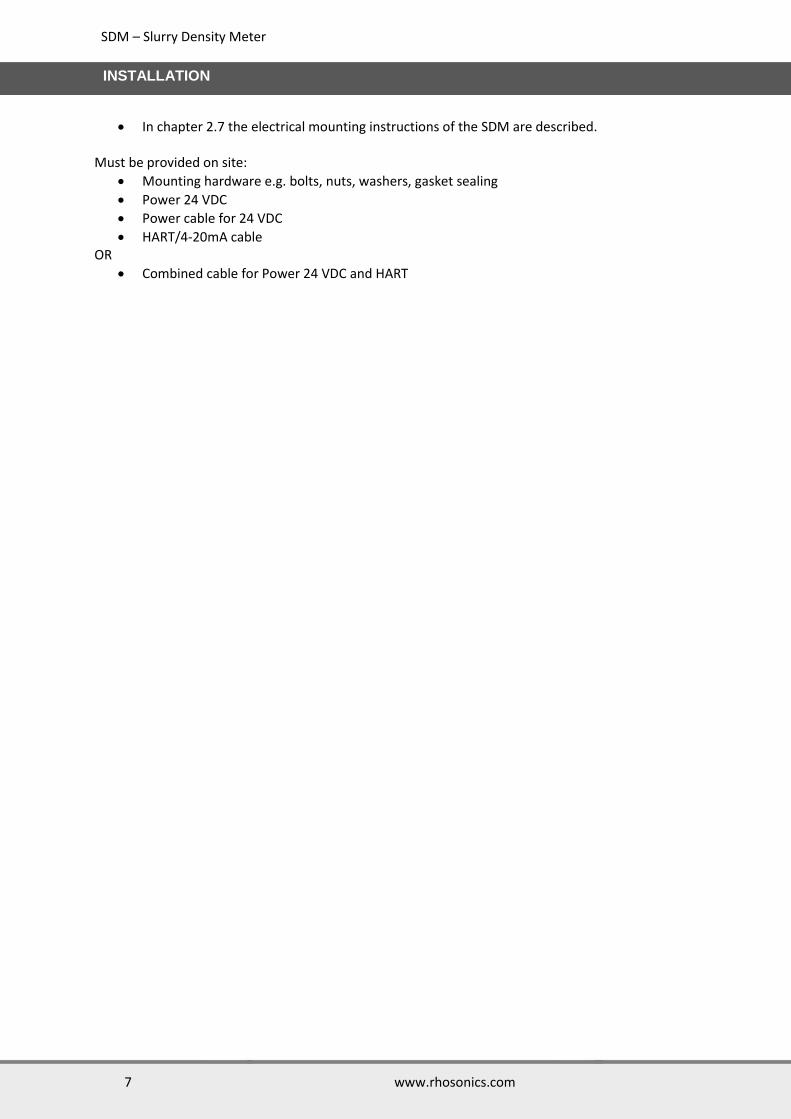
In chapter 2.7 the electrical mounting instructions of the SDM are described. Must be provided on site:
Mounting hardware e.g. bolts, nuts, washers, gasket sealing
Power 24 VDC
Power cable for 24 VDC
HART/4-20mA cable OR
Combined cable for Power 24 VDC and HART
SDM – Slurry Density Meter
8 www.rhosonics.com
INSTALLATION
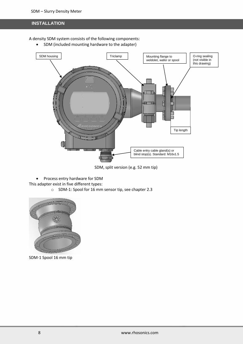
A density SDM system consists of the following components:
SDM (included mounting hardware to the adapter)
SDM, split version (e.g. 52 mm tip)
Process entry hardware for SDM This adapter exist in five different types:
o SDM-1: Spool for 16 mm sensor tip, see chapter 2.3
SDM-1 Spool 16 mm tip
Mounting flange to weldolet, wafer or spool
O-ring sealing (not visible in this drawing)
SDM housing
Cable entry cable gland(s) or blind stop(s). Standard: M16x1.5
Tip length
Triclamp

SDM – Slurry Density Meter
9 www.rhosonics.com
INSTALLATION
o SDM-2: Weldolet for 34 mm sensor tip, see chapter 2.4 o SDM-3: Weldolet for 52 mm sensor tip, see chapter 2.4
SDM-2 Weldolet 34 mm tip SDM-3 Weldolet 52 mm tip
o SDM-4: Wafer (UHMWPE or metal) for 146 mm sensor tip, see chapter 2.5 o SDM-5: Wafer (UHMWPE or metal) for 200 mm sensor tip, see chapter 2.5
SDM-4 wafer 146 mm tip SDM-5 wafer 200 mm tip
2.2 Selecting the SDM location The following guidelines apply to all SDM:
Install the SDM with 5xD length of straight pipe length upstream and 3xD of straight pipe length downstream.
Avoid installation in a pipe section where the SDM tip may wear fast Avoid installation near dosing valves. Vertical pipe installation is preferred when the flow goes in upstream direction, see chapter
2.2.1. Horizontal pipe installation: Sensor must be installed sidewise, see chapter 2.2.2.
SDM – Slurry Density Meter
10 www.rhosonics.com
INSTALLATION
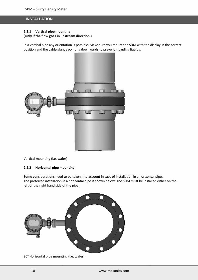
2.2.1 Vertical pipe mounting (Only if the flow goes in upstream direction.)
In a vertical pipe any orientation is possible. Make sure you mount the SDM with the display in the correct position and the cable glands pointing downwards to prevent intruding liquids.
Vertical mounting (i.e. wafer) 2.2.2 Horizontal pipe mounting Some considerations need to be taken into account in case of installation in a horizontal pipe. The preferred installation in a horizontal pipe is shown below. The SDM must be installed either on the left or the right hand side of the pipe.
90° Horizontal pipe mounting (i.e. wafer)

SDM – Slurry Density Meter
11 www.rhosonics.com
INSTALLATION
Maximum tolerance is 15⁰ from the horizontal line (downwards) as shown below.
105° Horizontal pipe mounting (i.e. wafer) 2.2.3 Analyzer head rotation The analyzer head can be rotated in any position (360°). Below some examples are shown.
Please make sure you will be very careful with rotating the housing. If not handled properly you can damage the SDM beyond repair, especially the spring loaded contacts in the sensor part. See also chapter 6.
Different housing positions
CAUTION:
SDM – Slurry Density Meter
12 www.rhosonics.com
INSTALLATION
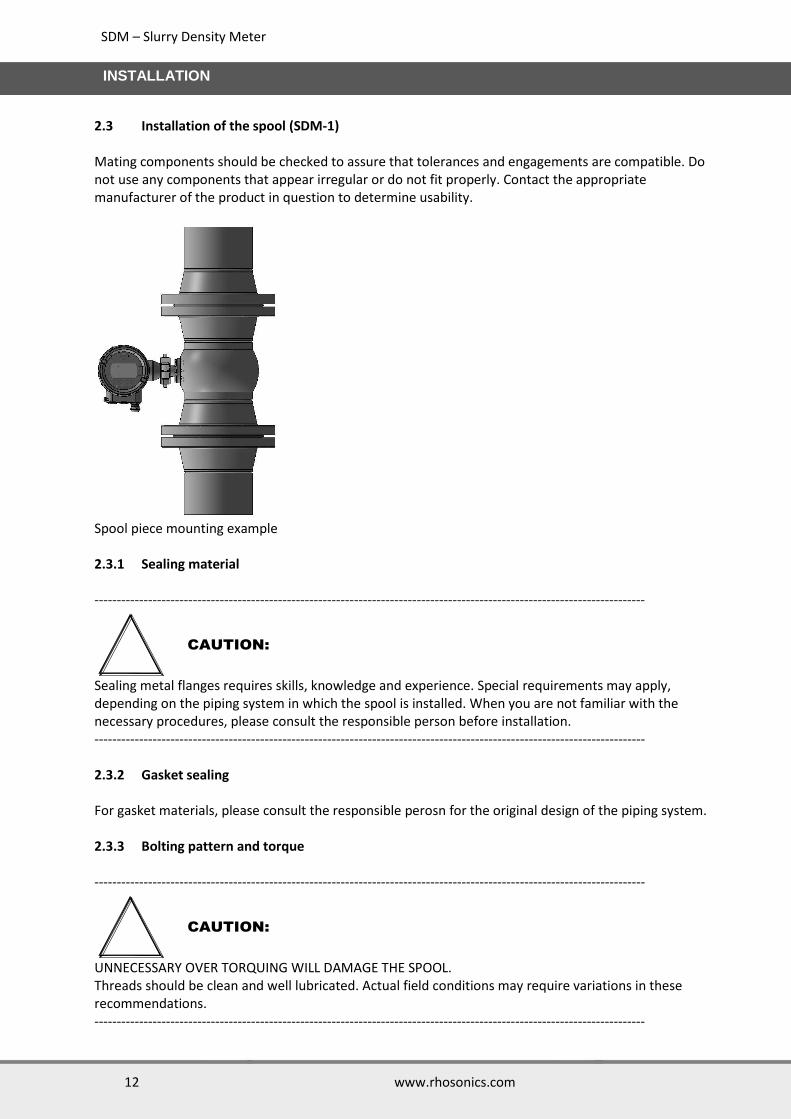
2.3 Installation of the spool (SDM-1)
Mating components should be checked to assure that tolerances and engagements are compatible. Do not use any components that appear irregular or do not fit properly. Contact the appropriate manufacturer of the product in question to determine usability.
Spool piece mounting example 2.3.1 Sealing material ---------------------------------------------------------------------------------------------------------------------------
Sealing metal flanges requires skills, knowledge and experience. Special requirements may apply, depending on the piping system in which the spool is installed. When you are not familiar with the necessary procedures, please consult the responsible person before installation. --------------------------------------------------------------------------------------------------------------------------- 2.3.2 Gasket sealing
For gasket materials, please consult the responsible perosn for the original design of the piping system. 2.3.3 Bolting pattern and torque
---------------------------------------------------------------------------------------------------------------------------
UNNECESSARY OVER TORQUING WILL DAMAGE THE SPOOL. Threads should be clean and well lubricated. Actual field conditions may require variations in these recommendations. ---------------------------------------------------------------------------------------------------------------------------
CAUTION:
CAUTION:

SDM – Slurry Density Meter
13 www.rhosonics.com
INSTALLATION
2.3.4 Instructions
1. Carefully align the pipe sections with the spool in order to avoid stress at the flange surface of the
spool. In addition, the piping must be secured and supported to prevent movement which can create excess stress and flange face damage.
2. Once the gasket is in place, align the bolt holes of the spool and the adjacent flange faces 3. Lightly lubricate and insert all bolts and washers and loosely apply the nuts 4. Number all bolts for record purposes 5. Make sure the faces of the mating surfaces are flush against gasket prior to bolting down the
flanges. 6. Tighten the nuts by hand until they are snug. Establish uniform pressure over the flange faces by
tightening the bolts in increments up described as below. 2.3.5 4 and 8 Bolt Flanges
First round - 30% of final torque (flange sequential order, crisscross) Second round- 60% of final torque (flange sequential order, crisscross) Third round - 100% of final torque (flange sequential order, crisscross) One final time after 24 hours - clockwise or counter clockwise sequentially around the flange
2.3.6 12 Bolt Flanges and More
First round - 20% of final torque (flange sequential order, crisscross) Second round - 40% of final torque (flange sequential order, crisscross) Third round - 80% of final torque (flange sequential order, crisscross) Fourth round - 100% of final torque (flange sequential order, crisscross) One final time after 24 hours - clockwise or counter clockwise sequentially around the flange.
In below table, torque values are given for Rhosonics metal spools (SDM-1) and metal wafers (SDM-4 or SDM-5). These values assume the flanged joint connects the spool to a CLASS 150 flange. These values are for Spiral Wound Gaskets, ASME B16.5.
Nom. OD Bolt hole
No.Bolts Size Bolts Preferred Torque per Bolt
(Inch) (mm) (mm) M… (ft lb) (Nm)
3 80 19 4 16 120 163
4 100 19 8 16 120 163
5 125 22.2 8 18 200 271
6 150 22.2 8 18 200 271
8 200 22.2 8 18 200 271
10 250 25.4 12 22 320 434
12 300 25.4 12 22 320 434
14 350 28.6 12 24 490 664
16 400 28.6 16 24 490 664
18 450 31.7 16 27 710 963
20 500 31.7 20 27 710 963
24 600 34.9 20 30 1000 1356

SDM – Slurry Density Meter
14 www.rhosonics.com
INSTALLATION
IMPORTANT: Rhosonics does not take responsibility for any of these torque values, they're theoretical values. These bolt torque values are intended for use as guidelines only and are based on ideal conditions, perfect flanges, flange alignment & new well lubricated bolts/nuts. Torque values are based on using weld-neck flanges and lubricated stud bolts with a 0.16 friction factor. Torque values for other gaskets, please contact your gasket supplier.
2.4 Weldolet installation (SDM-2 or SDM-3)
A weldolet is a metal piece which should be welded on an existing pipe. Please follow the next procedure to mount a weldolet.
Drill a hole of Ø36 mm in the process pipe, comply with vertical and horizontal installation conditions. Make sure no burrs are left inside the pipe.
Hole Ø36 mm in a vertical pipe.
Mount the weldolet in the drilled hole. Make sure the weldolet is aligned with the pipe. In addition, make sure the inside of the pipe is flush with the weldolet.
Weld the weldolet on the pipe. Make sure the weld is liquid-tight all around.
Vertical mount (weldolet)
SDM – Slurry Density Meter
15 www.rhosonics.com
INSTALLATION
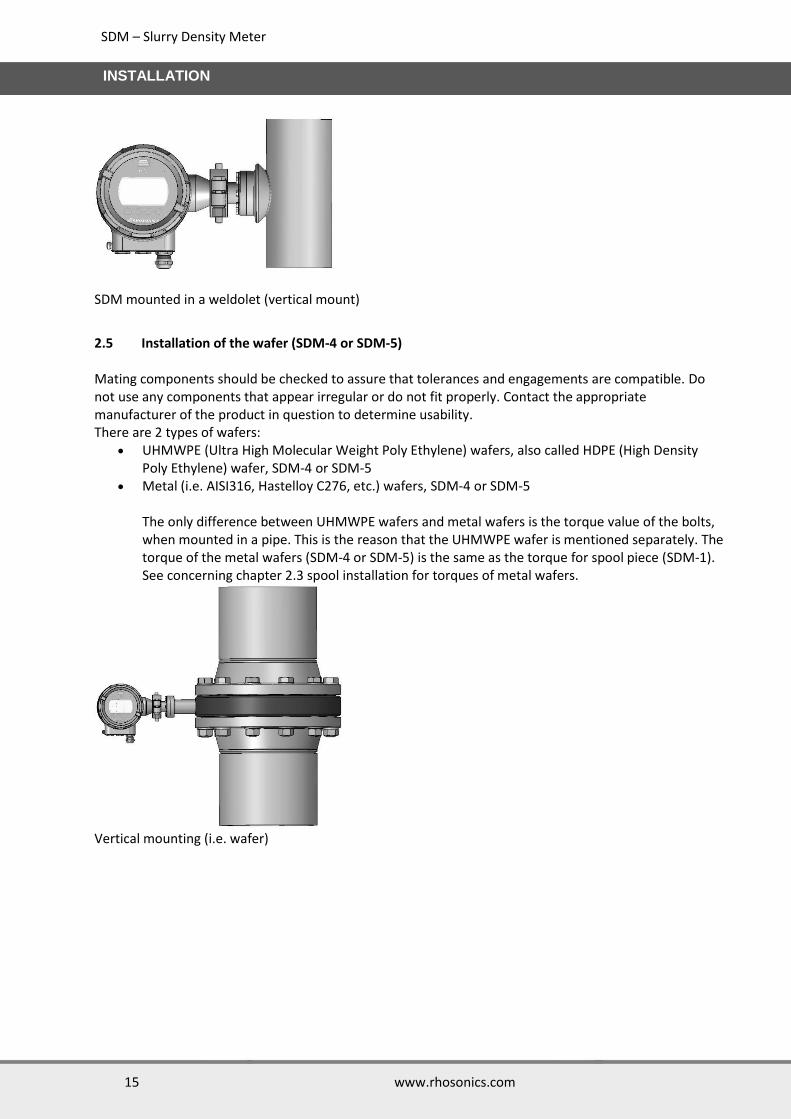
SDM mounted in a weldolet (vertical mount)
2.5 Installation of the wafer (SDM-4 or SDM-5)
Mating components should be checked to assure that tolerances and engagements are compatible. Do not use any components that appear irregular or do not fit properly. Contact the appropriate manufacturer of the product in question to determine usability. There are 2 types of wafers:
UHMWPE (Ultra High Molecular Weight Poly Ethylene) wafers, also called HDPE (High Density Poly Ethylene) wafer, SDM-4 or SDM-5
Metal (i.e. AISI316, Hastelloy C276, etc.) wafers, SDM-4 or SDM-5
The only difference between UHMWPE wafers and metal wafers is the torque value of the bolts, when mounted in a pipe. This is the reason that the UHMWPE wafer is mentioned separately. The torque of the metal wafers (SDM-4 or SDM-5) is the same as the torque for spool piece (SDM-1). See concerning chapter 2.3 spool installation for torques of metal wafers.
Vertical mounting (i.e. wafer)

SDM – Slurry Density Meter
16 www.rhosonics.com
INSTALLATION
2.5.1 Wafer (UHMWPE)
Sealing material (UHMWPE wafer) ---------------------------------------------------------------------------------------------------------------------------
Sealing of plastic pipe joints and metal flanges to plastic components requires skills, knowledge and experience. Special requirements may apply, depending on the piping system in which the wafer is installed. When you are not familiar with the necessary procedures, please consult the responsible person for the original design of the piping system. --------------------------------------------------------------------------------------------------------------------------- Non-gasket sealing UHMWPE flanges may be sealed without sealing material. The “memory” of pipe-grade UHMWPE makes it an ideal flange face sealing surface. It becomes its own “gasket flange”, and seals well when un-marred and torqued to meet or exceed the UHMWPE seating stress. When properly torqued, the joint between the wafer (UMMWPE) and the mating flange becomes self-sealing. Using this method, the specified seating torque needs to be applied, followed by a mandatory re-torque applied 4-hours to 24-hours after completion of the initial torque application. See following table for the torque to be used. Note that this is a torque table for 150 LBS flanges with a UHMWPE wafer. Gasket sealing The second method, (with gasket), uses a low gasket seating bolt torque, applied to a soft elastomeric gasket, for lower pressure applications (like landfill gas collection or use with torque-limited PVC or fiberglass flanges), followed by the mandatory re-torque 4 hours to 24-hours after the initial torque. Gasket material maybe either foamed PTFE, like Gylon, or an elastomer. For rubber lined pipes, additional gaskets are not recommended. Bolting pattern and torque ---------------------------------------------------------------------------------------------------------------------------
UNNECESSARY OVER TORQUING WILL DAMAGE THE WAFER. Threads should be clean and well lubricated. Actual field conditions may require variations in these recommendations. ---------------------------------------------------------------------------------------------------------------------------
CAUTION:
CAUTION:
SDM – Slurry Density Meter
17 www.rhosonics.com
INSTALLATION
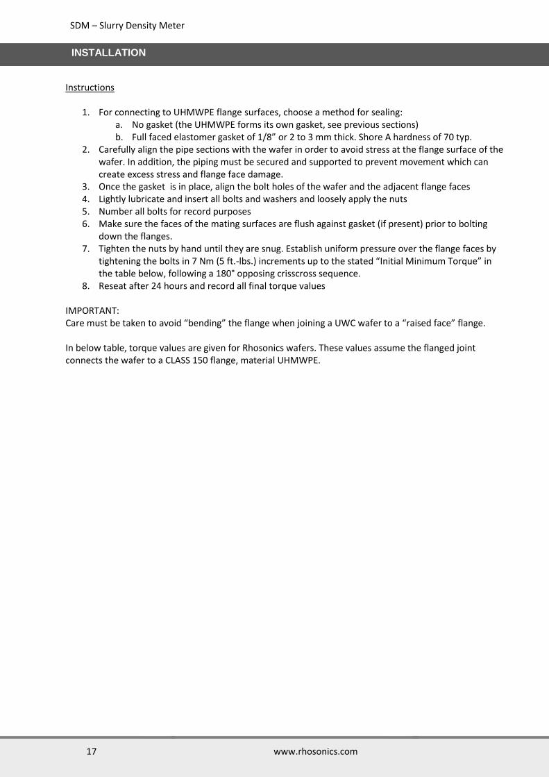
Instructions
1. For connecting to UHMWPE flange surfaces, choose a method for sealing: a. No gasket (the UHMWPE forms its own gasket, see previous sections) b. Full faced elastomer gasket of 1/8” or 2 to 3 mm thick. Shore A hardness of 70 typ.
2. Carefully align the pipe sections with the wafer in order to avoid stress at the flange surface of the wafer. In addition, the piping must be secured and supported to prevent movement which can create excess stress and flange face damage.
3. Once the gasket is in place, align the bolt holes of the wafer and the adjacent flange faces 4. Lightly lubricate and insert all bolts and washers and loosely apply the nuts 5. Number all bolts for record purposes 6. Make sure the faces of the mating surfaces are flush against gasket (if present) prior to bolting
down the flanges. 7. Tighten the nuts by hand until they are snug. Establish uniform pressure over the flange faces by
tightening the bolts in 7 Nm (5 ft.-lbs.) increments up to the stated “Initial Minimum Torque” in the table below, following a 180° opposing crisscross sequence.
8. Reseat after 24 hours and record all final torque values IMPORTANT: Care must be taken to avoid “bending” the flange when joining a UWC wafer to a “raised face” flange. In below table, torque values are given for Rhosonics wafers. These values assume the flanged joint connects the wafer to a CLASS 150 flange, material UHMWPE.
SDM – Slurry Density Meter
18 www.rhosonics.com
INSTALLATION
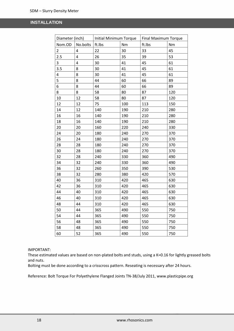
Diameter (inch) Initial Minimum Torque Final Maximum Torque
Nom.OD No.bolts ft.lbs Nm ft.lbs Nm
2 4 22 30 33 45
2.5 4 26 35 39 53
3 4 30 41 45 61
3.5 8 30 41 45 61
4 8 30 41 45 61
5 8 44 60 66 89
6 8 44 60 66 89
8 8 58 80 87 120
10 12 58 80 87 120
12 12 75 100 113 150
14 12 140 190 210 280
16 16 140 190 210 280
18 16 140 190 210 280
20 20 160 220 240 330
24 20 180 240 270 370
26 24 180 240 270 370
28 28 180 240 270 370
30 28 180 240 270 370
32 28 240 330 360 490
34 32 240 330 360 490
36 32 260 350 390 530
38 32 280 380 420 570
40 36 310 420 465 630
42 36 310 420 465 630
44 40 310 420 465 630
46 40 310 420 465 630
48 44 310 420 465 630
50 44 365 490 550 750
54 44 365 490 550 750
56 48 365 490 550 750
58 48 365 490 550 750
60 52 365 490 550 750
IMPORTANT: These estimated values are based on non-plated bolts and studs, using a K=0.16 for lightly greased bolts and nuts. Bolting must be done according to a crisscross pattern. Reseating is necessary after 24 hours. Reference: Bolt Torque For Polyethylene Flanged Joints TN-38/July 2011, www.plasticpipe.org

SDM – Slurry Density Meter
19 www.rhosonics.com
INSTALLATION
2.5.2 Wafer (metal, i.e. AISI 316)
The torque of the metal wafers (SDM-4 or SDM-5) is the same as the torque for spool piece (SDM-1). See chapter 2.3 for torques of metal wafers.
2.6 Installation of the SDM to the process adaptor The SDM flange has 8 bolt holes which is used in conjunction with a pipe adapter (weldolet, SDM-2 or SDM-3) or is intended to be fitted in a wafer section (SDM-4 or SDM-5) or a specially prepared spool section (SDM-1). The installation must be done with exclusively the following materials:
1. Hex capped bolts, M5x20 mm, AISI 316L, 8 pieces. 2. Washers M5, AISI 316L, 8 pieces 3. O-ring, Viton, 20.63x2.62 mm, 1 piece 4. O-ring, Viton, 29.82x2.62 mm, 1 piece
The user must ensure at all times that the used materials, in particular the O-rings, are compatible with the process fluid characteristics. Viton O-rings are mainly intended for acid applications. Prior to installation, the following must be assured:
1. The Weldolet port (SDM-2 or SDM-3), sensor adapter (SDM-4 or SDM-5) or sensor port (SDM-1) to which the SDM is installed, must be thoroughly cleaned and inspected for surface defects.
2. The O-rings must be new and free of defects. In addition, the type of material of the O-rings must be identified and verified for compatibility with the chemical and design temperature. Do not re-use O-rings, otherwise the proper sealing may be jeopardized.
3. The grooves in the SDM, in which the O-rings are seated, must be clean and inspected for surface defects. Before inserting the O-rings, some high vacuum grease may be applied to improve proper seating during installation.
4. The threaded pot holes in the weldolet (SDM-2 or SDM-3), wafer (SDM-4 or SDM-5) or flow-through cell (SDM-1) or as well as the bolts, must be clean and free of damage.
During installation, the following must be assured:
1. Insert the SDM as straight as possible, with respect to the axial orientation of the SDM port and display position.
2. The orientation of the conduit entry is preferably downwards and perpendicular to the pipe axis. 3. Tighten bolts with 4.2 Nm. 4. Do not cover the SDM flange with insulation material.
2.7 Electrical connections SDM The main electrical parts, which are used in all models are called the 9D-series. Specific electrical parts for a specific model are 3A (SDM) parts. Power supply Input voltage 18 - 30 V DC Maximum Input Power 8 W Admissible ripple voltage USS < 1V [<100Hz] USS < 10mV [100Hz . . 10kHz]
SDM – Slurry Density Meter
20 www.rhosonics.com
INSTALLATION
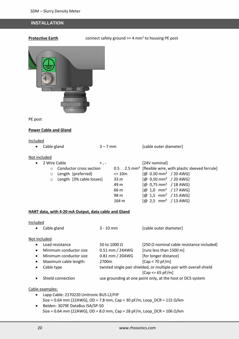
Protective Earth connect safety ground >= 4 mm2 to housing PE post
PE post Power Cable and Gland Included
Cable gland 3 – 7 mm [cable outer diameter] Not included
2 Wire Cable + , - [24V nominal] o Conductor cross section 0.5 . . 2.5 mm² [flexible wire, with plastic sleeved ferrule] o Length [preferred] <= 10m [@ 0.50 mm² / 20 AWG] o Length [3% cable losses] 33 m [@ 0,50 mm² / 20 AWG]
49 m [@ 0,75 mm² / 18 AWG] 66 m [@ 1,0 mm² / 17 AWG] 98 m [@ 1,5 mm² / 15 AWG] 164 m [@ 2,5 mm² / 13 AWG]
HART data, with 4-20 mA Output, data cable and Gland Included
Cable gland 3 - 10 mm [cable outer diameter] Not included
Load resistance 50 to 1000 Ω [250 Ω nominal cable resistance included]
Minimum conductor size 0.51 mm / 24AWG [runs less than 1500 m]
Minimum conductor size 0.81 mm / 20AWG [for longer distance]
Maximum cable length: 2700m [Cap < 70 pF/m]
Cable type twisted single pair shielded, or multiple pair with overall shield [Cap <= 65 pF/m]
Shield connection use grounding at one point only, at the host or DCS system
Cable examples:
Lapp Cable: 2170220 Unitronic BUS L2/FIP Size = 0.64 mm (22AWG), OD = 7.8 mm, Cap = 30 pF/m, Loop_DCR = 115 Ω/km
Belden: 3079E DataBus ISA/SP-50 Size = 0.64 mm (22AWG), OD = 8.0 mm, Cap = 28 pF/m, Loop_DCR = 106 Ω/km

SDM – Slurry Density Meter
21 www.rhosonics.com
INSTALLATION
2.7.1 USB port The USB-A connection is located on the front of the SDM. This USB-A port is used for:
Software update
Collecting Log data
Diagnostics
USB-A port on the front and cable entry cable glands
NOTE:
The cable glands can also be replaced by a Blind plug (standard: M16x1.5), if the entry is not used.
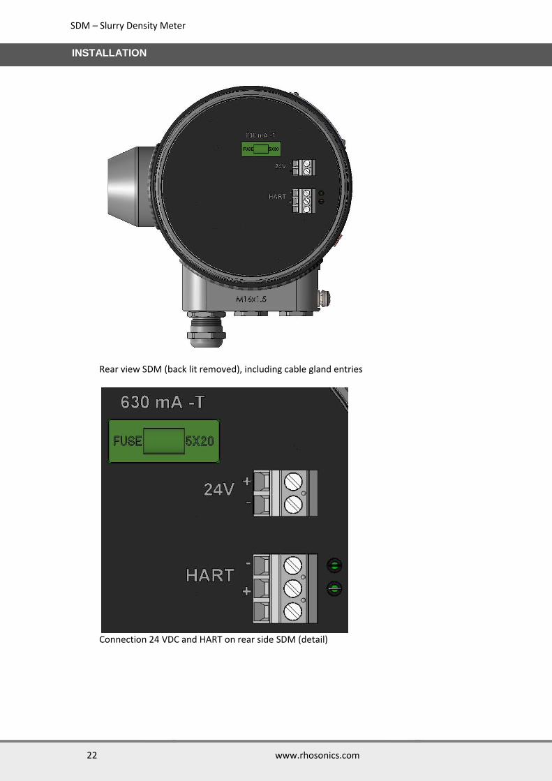
2.7.2 Connection 24 VDC power and HART The connection for the power and Hart is located in the inside of the SDM. The cable(s) entering the SDM housing through (a) cable gland(s). Inside the housing the cable(s) are connected to a screw connector. Below picture shows how to connect the power and HART. NOTE: Fuse specification
Blow Characteristic: Fast Acting Fuse Current: 630mA Fuse Size: 5mm x 20mm Voltage Rating VAC: 250V
Cable entry cable gland /stop (standard: M16x1.5)
USB-A port (front lit removed)
SDM – Slurry Density Meter
22 www.rhosonics.com
INSTALLATION
Rear view SDM (back lit removed), including cable gland entries
Connection 24 VDC and HART on rear side SDM (detail)

SDM – Slurry Density Meter
23 www.rhosonics.com
INSTALLATION
2.7.3 HART installation configurations The analyzer has an active 4-20mA HART output. This makes the physical device a Current Output Device. (Formerly Type C Field Device) Point to Point configuration in control loop: In the point to point hardware configuration, data is communicated both analog and digital. The secondary master is the communicator
Analyzer in a Point to Point configuration
2.7.3.1 Connection out of the control loop: For service and maintenance it might be necessary to connect with HART while the analyzer is disconnected from the DCS. The secondary master is connected across a 250Ω resistor. Both analog and digital communication is possible.
Analyzer connected out of the control loop
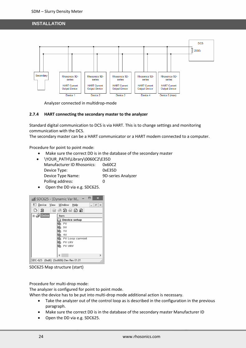
2.7.3.2 Multidrop configuration: The analyzer can be connected in multidrop-mode. This has some restrictions since it is a current output device. No more than 5 devices can be connected in multidrop-mode to the DCS to keep the current in the loop below 20mA. The loop current mode of the 9D-series analyzer has to be set to disabled and each device must have a unique polling address.
SDM – Slurry Density Meter
24 www.rhosonics.com
INSTALLATION
Analyzer connected in multidrop-mode
2.7.4 HART connecting the secondary master to the analyzer Standard digital communication to DCS is via HART. This is to change settings and monitoring communication with the DCS. The secondary master can be a HART communicator or a HART modem connected to a computer. Procedure for point to point mode:
Make sure the correct DD is in the database of the secondary master
\YOUR_PATH\Library\0060C2\E35D Manufacturer ID Rhosonics: 0x60C2 Device Type: 0xE35D Device Type Name: 9D-series Analyzer Polling address: 0
Open the DD via e.g. SDC625.
SDC625 Map structure (start) Procedure for multi-drop mode: The analyzer is configured for point to point mode. When the device has to be put into multi-drop mode additional action is necessary.
Take the analyzer out of the control loop as is described in the configuration in the previous paragraph.
Make sure the correct DD is in the database of the secondary master Manufacturer ID
Open the DD via e.g. SDC625.

SDM – Slurry Density Meter
25 www.rhosonics.com
INSTALLATION
Make sure that polling address 0 is checked for making connection.
When connection is established give the device a unique polling address (preferably smaller than 15) .
Do this by changing Poll addr: Device setup->Detailed setup->Output condition->HART output->Poll addr
For multidrop mode it is necessary to disable the current output:
Device setup->Detailed setup->Output condition->Analog output->Loop current mode.
The analyzer can now be installed according the multi-drop mode configuration.
When reconnecting the secondary master make sure the correct polling address is checked.
SDM – Slurry Density Meter
26 www.rhosonics.com
INSTALLATION
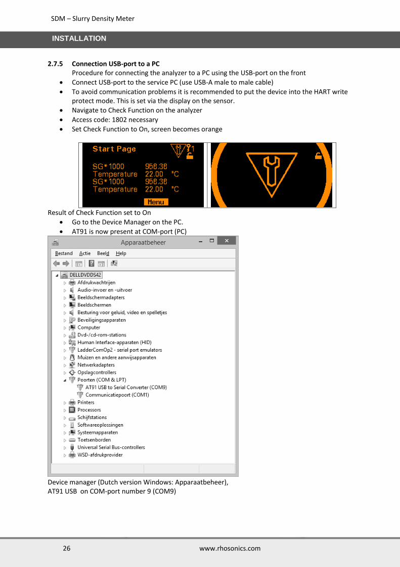
2.7.5 Connection USB-port to a PC Procedure for connecting the analyzer to a PC using the USB-port on the front
Connect USB-port to the service PC (use USB-A male to male cable)
To avoid communication problems it is recommended to put the device into the HART write protect mode. This is set via the display on the sensor.
Navigate to Check Function on the analyzer
Access code: 1802 necessary
Set Check Function to On, screen becomes orange
Result of Check Function set to On
Go to the Device Manager on the PC.
AT91 is now present at COM-port (PC)
Device manager (Dutch version Windows: Apparaatbeheer), AT91 USB on COM-port number 9 (COM9)

SDM – Slurry Density Meter
27 www.rhosonics.com
INSTALLATION
Start-up Rhosonics_SA _9D_##_##.exe
COM9 selected
Connection is made between sensor and service program. Whenever the green light is on and the echo is visible.

SDM – Slurry Density Meter
28 www.rhosonics.com
OPERATION
3. Operation
3.1 Introduction The Operations for the analyzer can be divided in 3 options each with its own user interface:
Operations on the LCD screen, see chapter 3.2
Operations via HART, see chapter 3.3
Operations through the USB-port, see chapter 3.4 The choice for each user interface is dependent on the type of user. Setup is as follows:
Operating overview with:type of user interface, type of user and access level
SDM – Slurry Density Meter
29 www.rhosonics.com
OPERATION
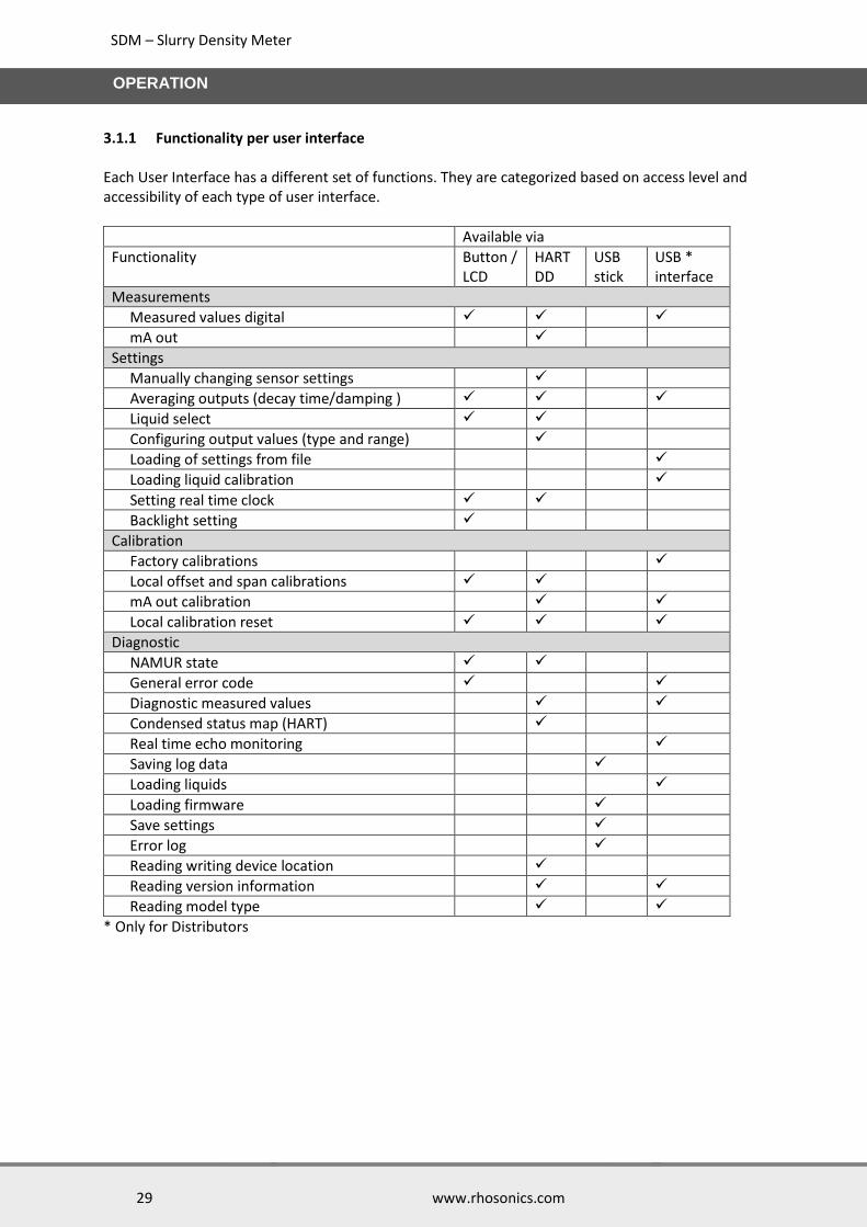
3.1.1 Functionality per user interface Each User Interface has a different set of functions. They are categorized based on access level and accessibility of each type of user interface.
Available via
Functionality Button / LCD
HART DD
USB stick
USB * interface
Measurements
Measured values digital
mA out
Settings
Manually changing sensor settings
Averaging outputs (decay time/damping )
Liquid select
Configuring output values (type and range)
Loading of settings from file
Loading liquid calibration
Setting real time clock
Backlight setting
Calibration
Factory calibrations
Local offset and span calibrations
mA out calibration
Local calibration reset
Diagnostic
NAMUR state
General error code
Diagnostic measured values
Condensed status map (HART)
Real time echo monitoring
Saving log data
Loading liquids
Loading firmware
Save settings
Error log
Reading writing device location
Reading version information
Reading model type
* Only for Distributors
SDM – Slurry Density Meter
30 www.rhosonics.com
OPERATION
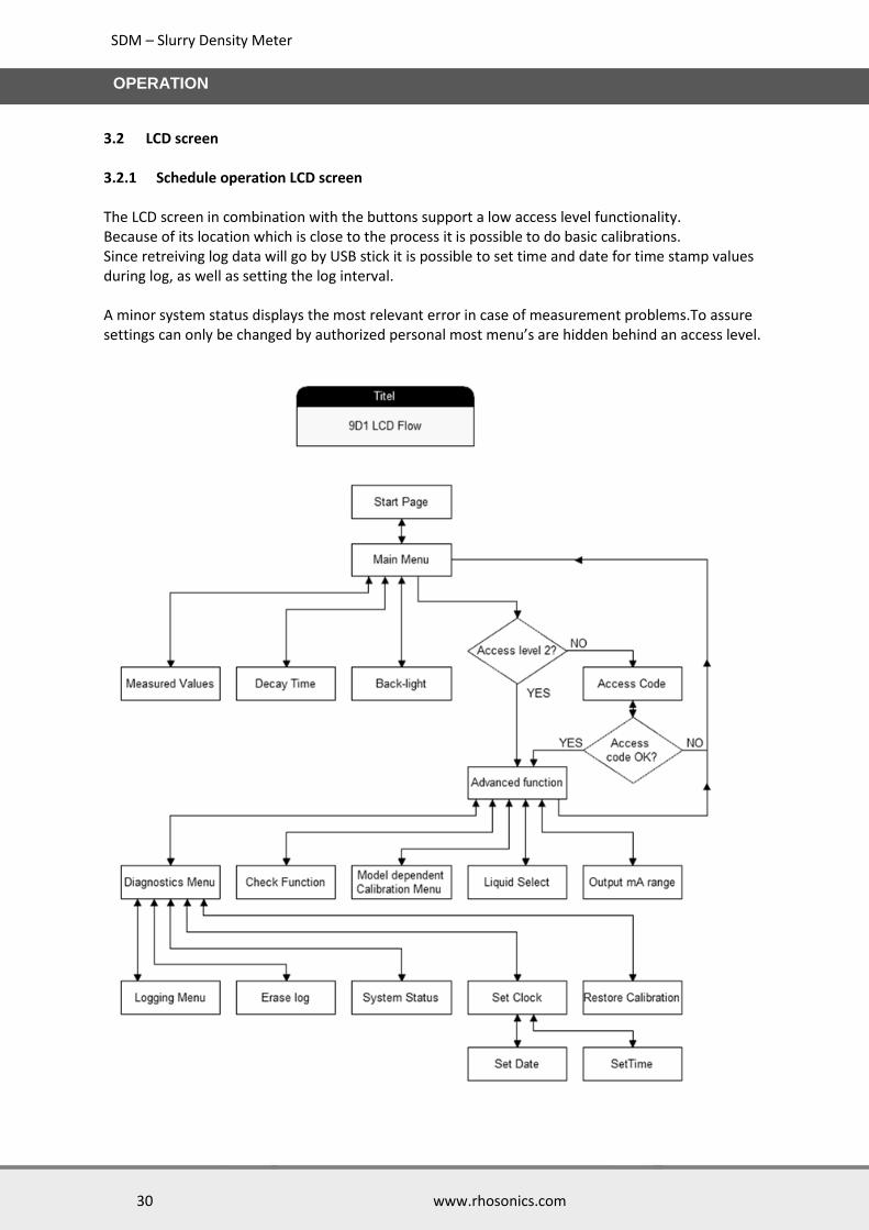
3.2 LCD screen 3.2.1 Schedule operation LCD screen The LCD screen in combination with the buttons support a low access level functionality. Because of its location which is close to the process it is possible to do basic calibrations. Since retreiving log data will go by USB stick it is possible to set time and date for time stamp values during log, as well as setting the log interval. A minor system status displays the most relevant error in case of measurement problems.To assure settings can only be changed by authorized personal most menu’s are hidden behind an access level.
SDM – Slurry Density Meter
31 www.rhosonics.com
OPERATION
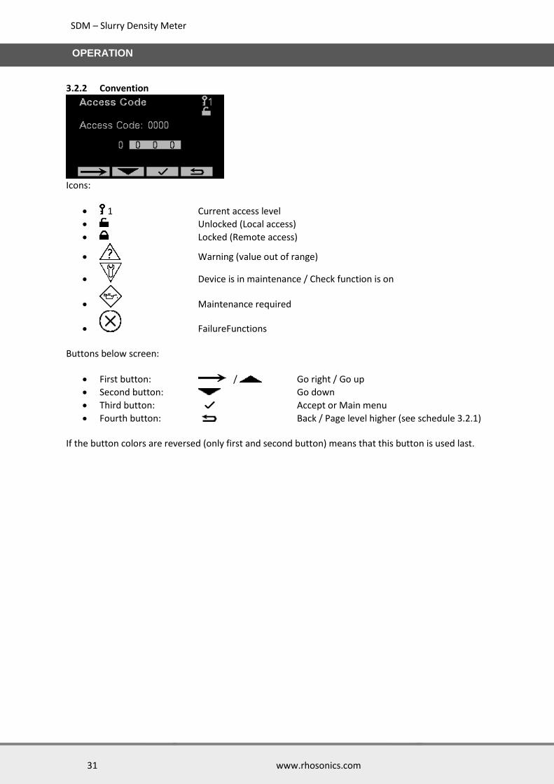
3.2.2 Convention
Icons:
1 Current access level
Unlocked (Local access)
Locked (Remote access)
Warning (value out of range)
Device is in maintenance / Check function is on
Maintenance required
FailureFunctions Buttons below screen:
First button: / Go right / Go up
Second button: Go down
Third button: Accept or Main menu
Fourth button: Back / Page level higher (see schedule 3.2.1) If the button colors are reversed (only first and second button) means that this button is used last.
SDM – Slurry Density Meter
32 www.rhosonics.com
OPERATION
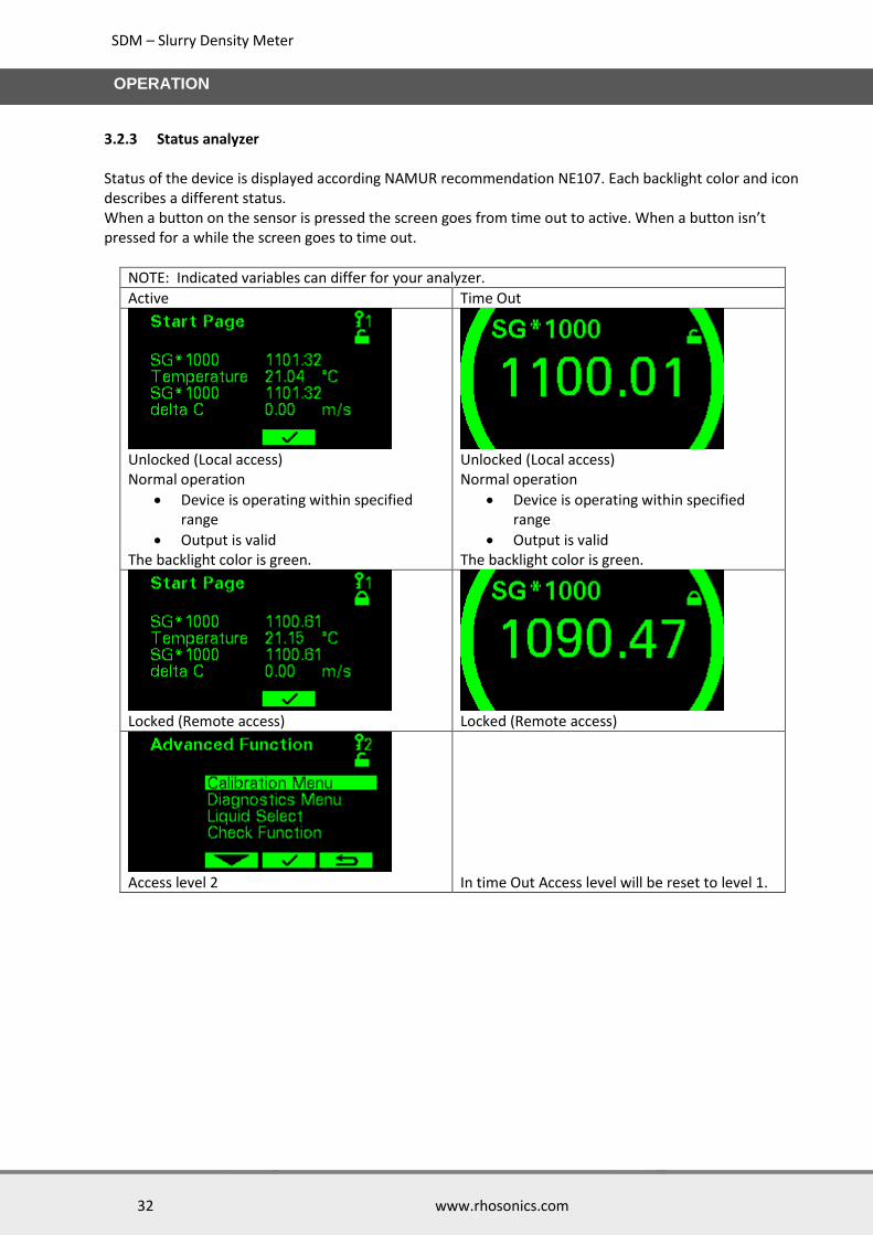
3.2.3 Status analyzer Status of the device is displayed according NAMUR recommendation NE107. Each backlight color and icon describes a different status. When a button on the sensor is pressed the screen goes from time out to active. When a button isn’t pressed for a while the screen goes to time out.
NOTE: Indicated variables can differ for your analyzer.
Active Time Out
Unlocked (Local access) Normal operation
Device is operating within specified range
Output is valid The backlight color is green.
Unlocked (Local access) Normal operation
Device is operating within specified range
Output is valid The backlight color is green.
Locked (Remote access)
Locked (Remote access)
Access level 2
In time Out Access level will be reset to level 1.

SDM – Slurry Density Meter
33 www.rhosonics.com
OPERATION
NOTE: Indicated variables can differ for your analyzer.
Value Out Of Range
Device is operating outside specified range
Internal diagnoses indicate deviations from measured or set values
Output is still valid Icon in upper right corner and backlight change into yellow.
Value Out Of Range
Device is operating outside specified range
Internal diagnoses indicate deviations from measured or set values
Output is still valid Backlight in yellow. Icon and measurement values are alternating.
Maintenance Required
Maintenance on device necessary
Output values still valid Icon in upper right corner and backlight change into blue.
Maintenance Required
Maintenance on device necessary
Output values still valid Backlight in blue. Icon and measurement values are alternating.
Function check
Device is in maintenance
Check Function is on
Output values temporarily invalid Icon in upper right corner and backlight change into orange.
Function check
Device is in maintenance
Check Function is on
Output values temporarily invalid Backlight in orange. Icon and measurement values are alternating.
Failure
Replace device Icon in upper right corner and backlight change into red.
Failure
Replace device Backlight in red. Icon and measurement values are alternating.
SDM – Slurry Density Meter
34 www.rhosonics.com
OPERATION
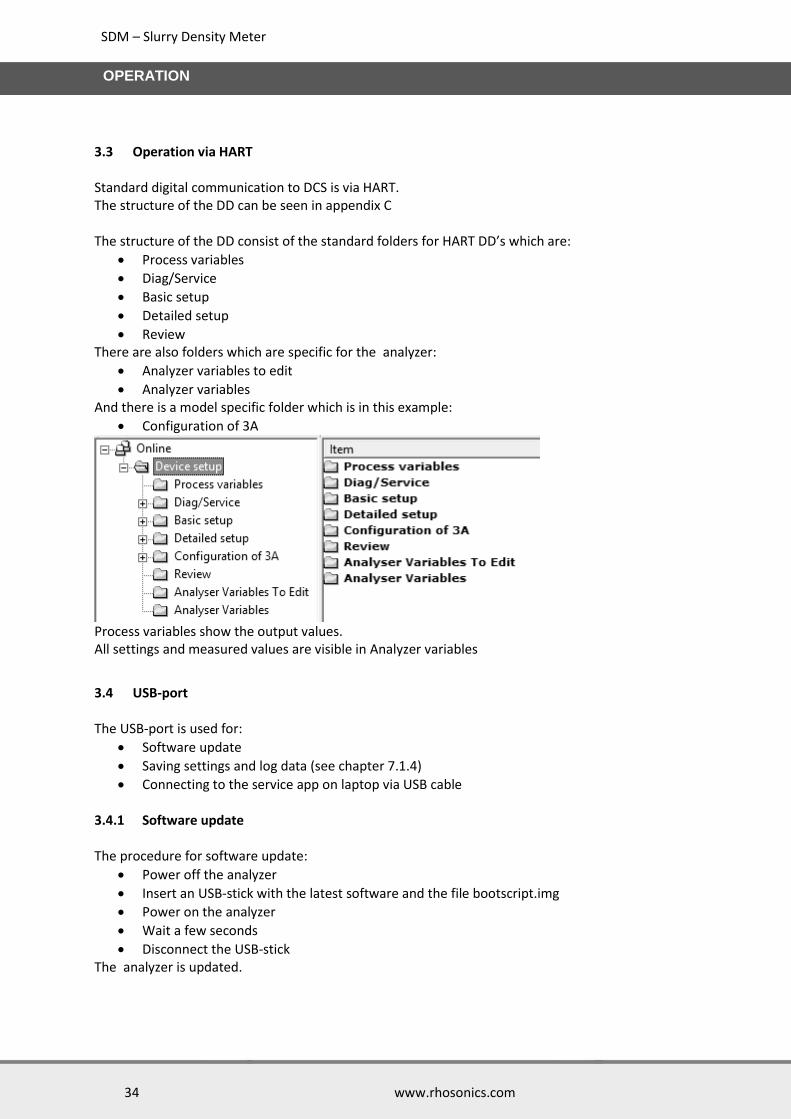
3.3 Operation via HART Standard digital communication to DCS is via HART. The structure of the DD can be seen in appendix C The structure of the DD consist of the standard folders for HART DD’s which are:
Process variables
Diag/Service
Basic setup
Detailed setup
Review There are also folders which are specific for the analyzer:
Analyzer variables to edit
Analyzer variables And there is a model specific folder which is in this example:
Configuration of 3A
Process variables show the output values. All settings and measured values are visible in Analyzer variables
3.4 USB-port The USB-port is used for:
Software update
Saving settings and log data (see chapter 7.1.4)
Connecting to the service app on laptop via USB cable 3.4.1 Software update The procedure for software update:
Power off the analyzer
Insert an USB-stick with the latest software and the file bootscript.img
Power on the analyzer
Wait a few seconds
Disconnect the USB-stick The analyzer is updated.
SDM – Slurry Density Meter
35 www.rhosonics.com
OPERATION
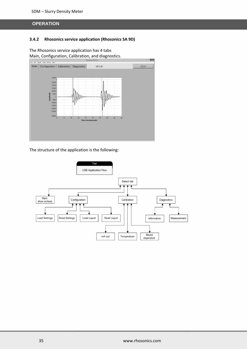
3.4.2 Rhosonics service application (Rhosonics SA 9D) The Rhosonics service application has 4 tabs Main, Configuration, Calibration, and diagnostics.
The structure of the application is the following:
SDM – Slurry Density Meter
36 www.rhosonics.com
CONFIGURATION
4. Configuration
4.1 Introduction The Configurations for the analyzer can be divided in 3 options.
Operations on the LCD screen, see chapter 4.2
Operations through the HART communication, see chapter 4.3
Operations through the USB-port, see chapter 4.4
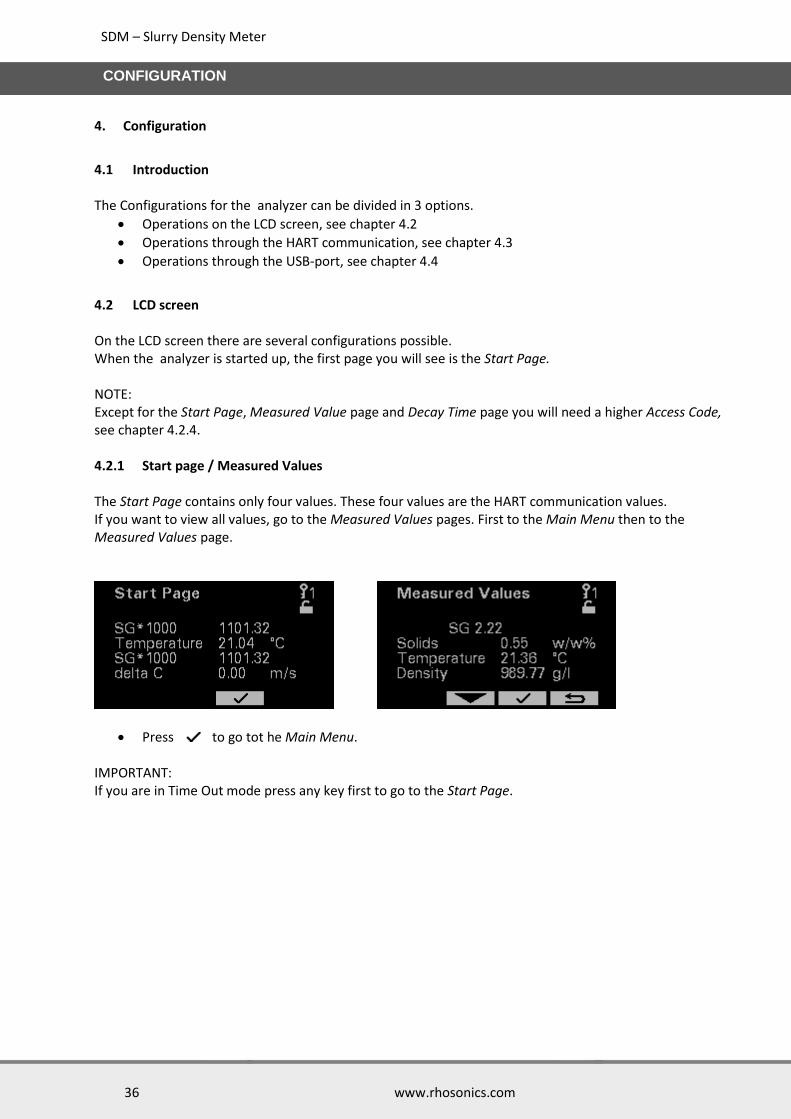
4.2 LCD screen On the LCD screen there are several configurations possible. When the analyzer is started up, the first page you will see is the Start Page. NOTE: Except for the Start Page, Measured Value page and Decay Time page you will need a higher Access Code, see chapter 4.2.4. 4.2.1 Start page / Measured Values The Start Page contains only four values. These four values are the HART communication values. If you want to view all values, go to the Measured Values pages. First to the Main Menu then to the Measured Values page.
Press to go tot he Main Menu. IMPORTANT: If you are in Time Out mode press any key first to go to the Start Page.
SDM – Slurry Density Meter
37 www.rhosonics.com
CONFIGURATION
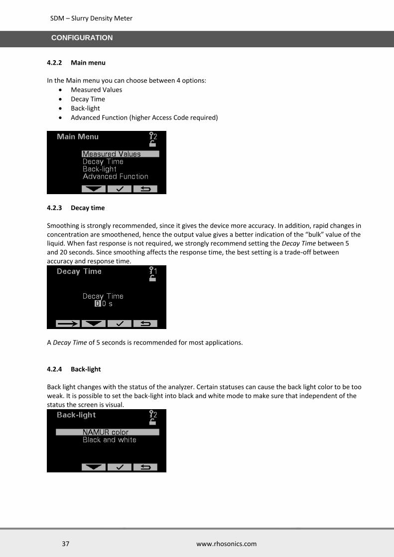
4.2.2 Main menu In the Main menu you can choose between 4 options:
Measured Values
Decay Time
Back-light
Advanced Function (higher Access Code required)
4.2.3 Decay time Smoothing is strongly recommended, since it gives the device more accuracy. In addition, rapid changes in concentration are smoothened, hence the output value gives a better indication of the “bulk” value of the liquid. When fast response is not required, we strongly recommend setting the Decay Time between 5 and 20 seconds. Since smoothing affects the response time, the best setting is a trade-off between accuracy and response time.
A Decay Time of 5 seconds is recommended for most applications. 4.2.4 Back-light Back light changes with the status of the analyzer. Certain statuses can cause the back light color to be too weak. It is possible to set the back-light into black and white mode to make sure that independent of the status the screen is visual.

SDM – Slurry Density Meter
38 www.rhosonics.com
CONFIGURATION
4.2.5 Access Code To enter the Advanced Function and all function after the Advanced Function page a higher Access Code is necessary. Access code for level 2 is 1802. To enter this Access Code please follow below procedure:
On the Start Page press
In Main Menu scroll to Advanced Function, using and buttons.
Access Code page will pop-up if you are not already in Access Code 2
Enter Access Code using and buttons.
After entering the Access Code press the button.
The Advanced Function page is on the screen now.
4.2.6 Advanced Function On the Advanced Function page you can choose between 5 options:
Calibration Menu, see chapter 5
Diagnostics Menu, see chapter 7
Liquid Select
Check Function
Output mA Range
4.2.7 Liquid Select On the Liquid Select page you can choose 2 options:
Water measurement: only water can be measured, polynomials for water are standardly stored in the analyzer.
Normal operation: a set of polynomials is loaded into the analyzer. This setting is specifically for its application.

SDM – Slurry Density Meter
39 www.rhosonics.com
CONFIGURATION
4.2.8 Check Function The Check Function can be used for two things:
When HART is used the DCS is warned that the analyzer is in maintenance/service, so values sent to the DCS can be wrong values.
Another function is that a COM-port is configured for a service PC
4.2.9 Output mA range Setting Output mA range is used to assign which value is corresponding to the 4 and 20mA range of the analog output. As a consequence the analyzer (and mA out) will go into the out of specification status, when the measured value will go out of these range. Screens below shows the menu and the pages where the upper and lower range value can be set.

SDM – Slurry Density Meter
40 www.rhosonics.com
CONFIGURATION
4.3 HART communication To set up the HART configuration you need a program called DD edit With this program you can setup the HART communication. Even without using HART there is a possibility to use the 4-20 mA Output of the HART. Therefore you only need to setup the Primary Variable. This is described in this chapter. HART has four standard digital outputs namely:
PV Primary Variable
SV Secondary Variable
TV Ternary Variable
4V Quaternary Variable NOTE: The analog signal (4-20 mA Output) is the same as the Primary Variable. This must be set correctly whether the customer uses HART or not. 4.3.1 Setting the Primary Variable / assigning 4-20mA output It is possible to assign 4 variables for the HART communication, these are called Dynamic Variables. The first one is called the Primary Variable (PV) this value is assigned to the 4-20mA analogue. All 4 dynamic variables (PV, SV, TV and 4V) can be obtained digitally by a DCS which support HART.
There are 8 standard variables you can choose from:
Device Variable 0: Concentration 1
Device Variable 1: Concentration 2
Device Variable 2: Sound Speed
Device Variable 3: Temperature
Device Variable 4: SGX1000
Device Variable 5: Acoustic Impedance
Device Variable 6: Solids
Device Variable 7: Power Liquid Echo NOTE: It can be that the specific analyzer model doesn’t measure a specific Device Variable. In that case it is not recommended to select this Device Variable. Procedure:
Connect the secondary master to the analyzer
Make sure the correct DD is in the database: o \YOUR_PATH\Library\0060C2\E35D o (Manufacturer ID = 0x60C2) o (Device ID = 0xE35D)
Open Analyzer.ddl
Build DD [Ctrl + M]
Execute [Ctrl + F5]
SDC625 is opened

SDM – Slurry Density Meter
41 www.rhosonics.com
CONFIGURATION
SDC625 Map structure (start)
Open Map Dynamic Var Mapping (OnlineDevice Setup Detailed setup Output condition HART output Dynamic Var Mapping)
Double click PV is, SV is, Tv is or QV is
PV is setting in map Dynamic Var Mapping
Choose variable for PV is, SV is, TV is and QV is
4.3.2 Configure 4-20 mA Output This procedure is to specify the 4-20 mA Output.
The PV LRV (Primary Variable Lower Range Value) correspond to 4 mA
The PV URV (Primary Variable Upper Range Value) correspond to 20 mA
The PV Alrm typ (Primary Variable Alarm Type) is the Error reaction mode
The Loop current mode has to be Enabled (Disabled is Multidrop-mode)
The Loop test sets the output to a set value
The D/A trim trims the low and high value on digital level
SDM – Slurry Density Meter
42 www.rhosonics.com
CONFIGURATION
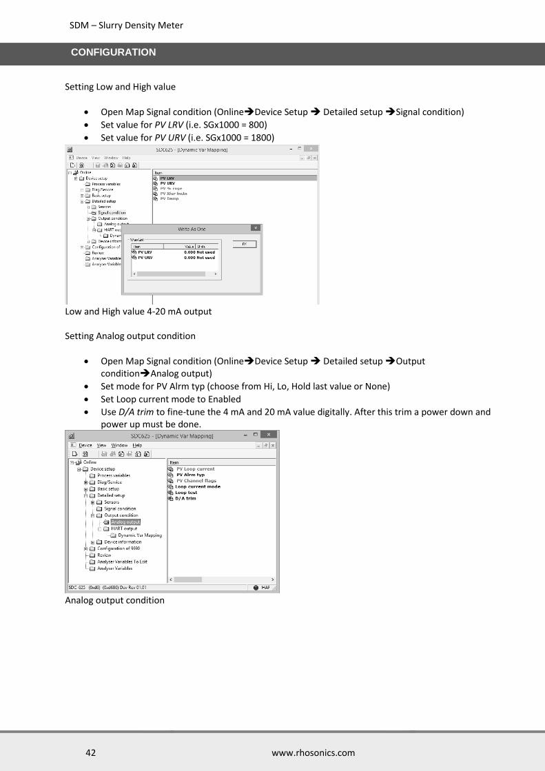
Setting Low and High value
Open Map Signal condition (OnlineDevice Setup Detailed setup Signal condition)
Set value for PV LRV (i.e. SGx1000 = 800)
Set value for PV URV (i.e. SGx1000 = 1800)
Low and High value 4-20 mA output Setting Analog output condition
Open Map Signal condition (OnlineDevice Setup Detailed setup Output conditionAnalog output)
Set mode for PV Alrm typ (choose from Hi, Lo, Hold last value or None)
Set Loop current mode to Enabled
Use D/A trim to fine-tune the 4 mA and 20 mA value digitally. After this trim a power down and power up must be done.
Analog output condition
SDM – Slurry Density Meter
43 www.rhosonics.com
CONFIGURATION
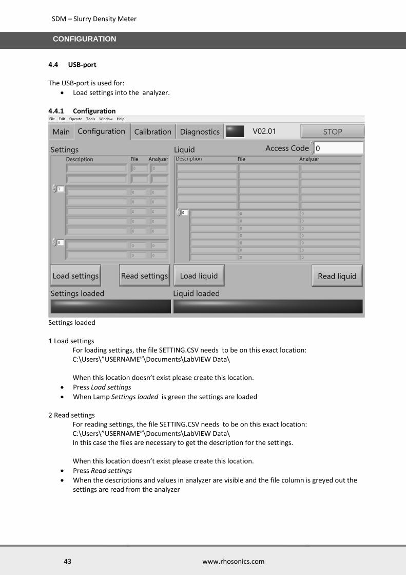
4.4 USB-port The USB-port is used for:
Load settings into the analyzer. 4.4.1 Configuration
Settings loaded 1 Load settings For loading settings, the file SETTING.CSV needs to be on this exact location: C:\Users\”USERNAME”\Documents\LabVIEW Data\ When this location doesn’t exist please create this location.
Press Load settings
When Lamp Settings loaded is green the settings are loaded 2 Read settings For reading settings, the file SETTING.CSV needs to be on this exact location: C:\Users\”USERNAME”\Documents\LabVIEW Data\ In this case the files are necessary to get the description for the settings. When this location doesn’t exist please create this location.
Press Read settings
When the descriptions and values in analyzer are visible and the file column is greyed out the settings are read from the analyzer
SDM – Slurry Density Meter
44 www.rhosonics.com
CONFIGURATION
3 Load liquid The liquid calibration is loaded from a liquid file this file starts with RLS and has the csv file-extension. This file needs to be on this exact location: C:\Users\”USERNAME”\Documents\LabVIEW Data\ When this location doesn’t exist please create this location.
Press Load liquid
When Lamp Liquid loaded is green the settings are loaded 4 Read liquid To read the liquid from the analyzer a liquid file is needed. The name of this file starts with RLS and has the csv file-extension. This file needs to be on this exact location: C:\Users\”USERNAME”\Documents\LabVIEW Data\ The file is needed to provide the description. When this location doesn’t exist please create this location.
Press Read liquid
When the descriptions and values in the analyzer are visible and the file column is grey, the liquid calibration is read from the analyzer
Configuring minimum and maximum values for the 4-20 mA output
Open “SETTING.csv” file in Excel
Change the values for “PV lower range value” and “PV upper range value”
Save the file (keep .csv extension)
Press Load settings
When Lamp Settings loaded is green the settings are loaded The minimum and maximum values for the 4-20 mA output are now configured. Changing Primary, Secondary, Ternary and Quaternary values for HART output
Open “SETTING.csv” file.
Change the values for “primary/secondary/ternary/quartinary dynamicVarConfig”, all available quantities have been included in the csv-file
Save the file (keep .csv extension)
Press Load settings
When Lamp Settings loaded is green the settings are loaded The Primary, Secondary, Ternary and Quaternary values for HART output are now set.
SDM – Slurry Density Meter
45 www.rhosonics.com
CALIBRATION LCD SCREEN
5. Calibration LCD screen
5.1 Calibration Menu In the Calibration Menu you can choose out of three calibrations:
Temperature
S.G. x 1000
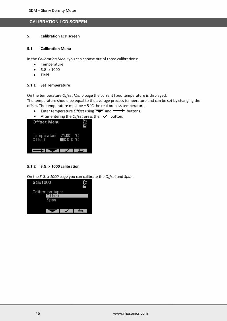
Field 5.1.1 Set Temperature On the temperature Offset Menu page the current fixed temperature is displayed. The temperature should be equal to the average process temperature and can be set by changing the offset. The temperature must be ± 5 °C the real process temperature.
Enter temperature Offset using and buttons.
After entering the Offset press the button.
5.1.2 S.G. x 1000 calibration On the S.G. x 1000 page you can calibrate the Offset and Span.
SDM – Slurry Density Meter
46 www.rhosonics.com
CALIBRATION LCD SCREEN
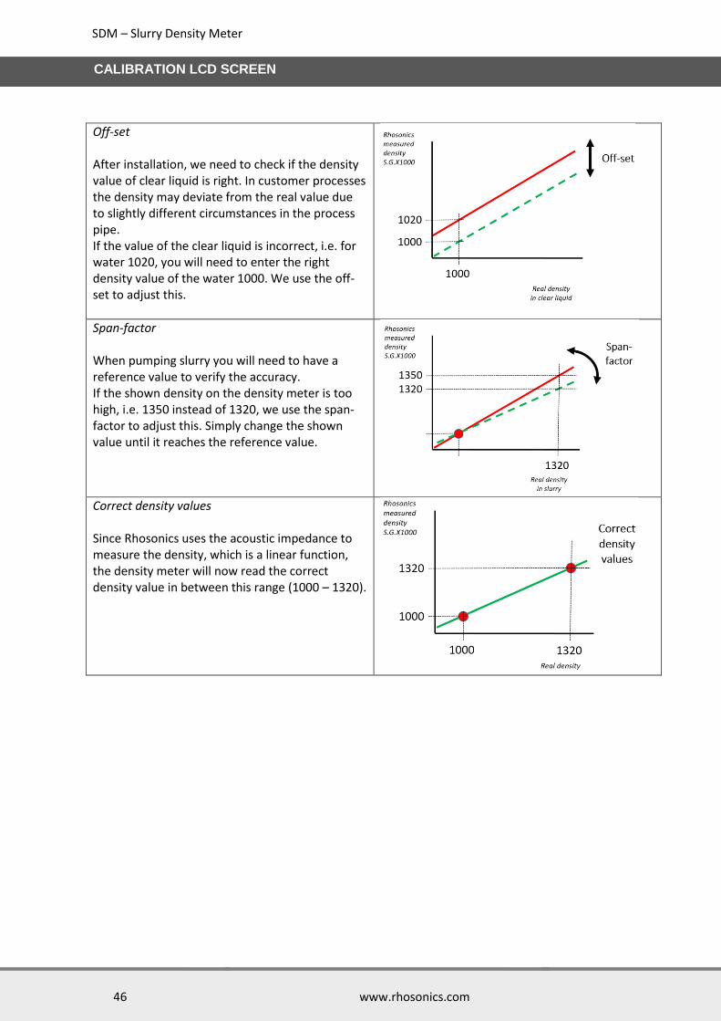
Off-set After installation, we need to check if the density value of clear liquid is right. In customer processes the density may deviate from the real value due to slightly different circumstances in the process pipe. If the value of the clear liquid is incorrect, i.e. for water 1020, you will need to enter the right density value of the water 1000. We use the off-set to adjust this.
Span-factor When pumping slurry you will need to have a reference value to verify the accuracy. If the shown density on the density meter is too high, i.e. 1350 instead of 1320, we use the span-factor to adjust this. Simply change the shown value until it reaches the reference value.
Correct density values
Since Rhosonics uses the acoustic impedance to measure the density, which is a linear function, the density meter will now read the correct density value in between this range (1000 – 1320).

SDM – Slurry Density Meter
47 www.rhosonics.com
CALIBRATION LCD SCREEN
Offset Menu page: The offset shifts the indicated SGx1000 to the desired value, without influencing the sensitivity.
Enter S.G. x 1000 Offset using and buttons.
After entering the Offset press the button.
Span Menu page: For some applications the sensitivity of the SDM is either too high or too low. When that is the case the span has to be adjusted. The way of configuring the span factor is described in earlier in this chapter. It is however not necessary to completely understand that explanation. By changing the span you get the expected result of the calibration
Enter S.G. x 1000 Span using and buttons.
After entering the Span press the button.
5.1.3 Field calibration Field calibration has no effect for the SDM.
SDM – Slurry Density Meter
48 www.rhosonics.com
MAINTENANCE
6. Maintenance
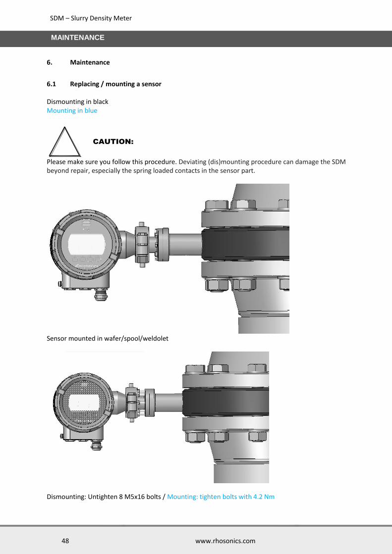
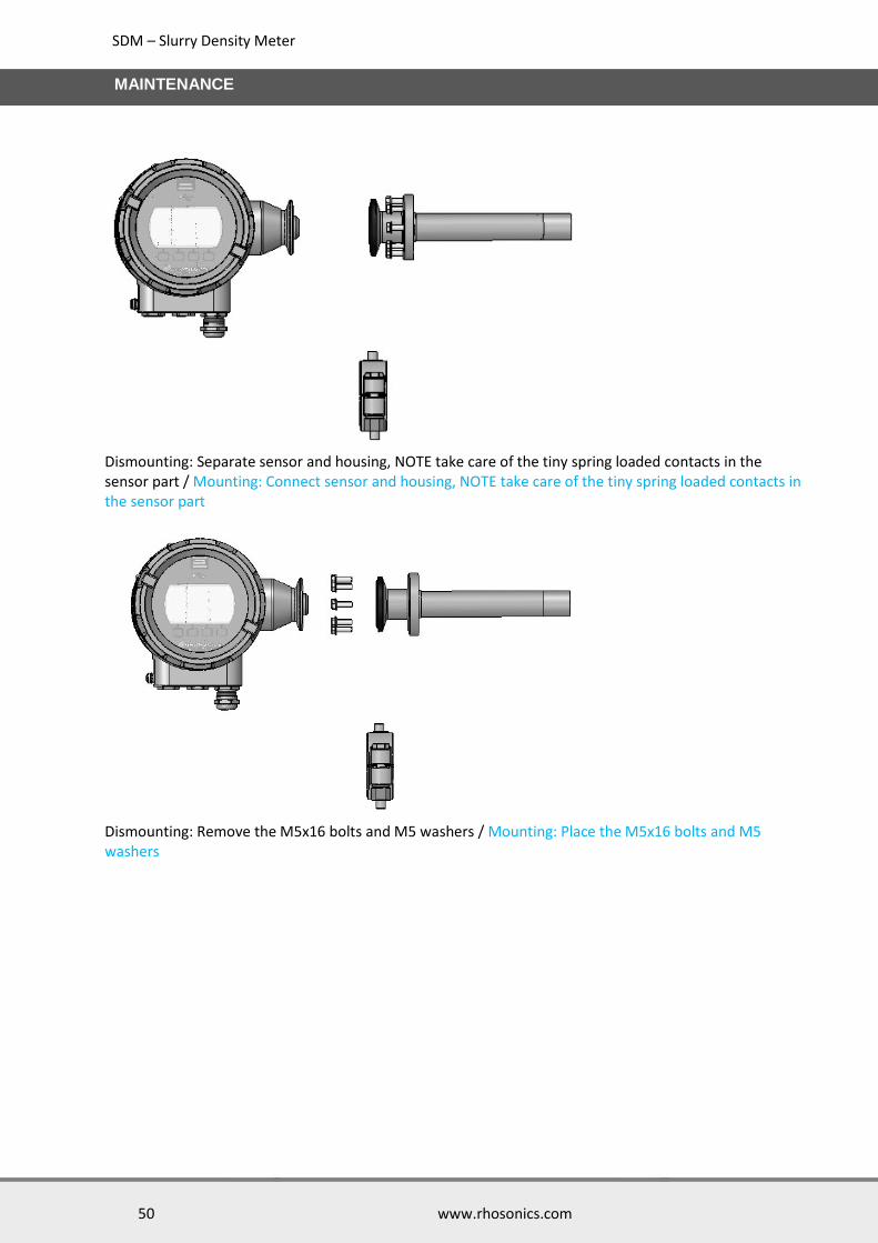
6.1 Replacing / mounting a sensor Dismounting in black Mounting in blue
Please make sure you follow this procedure. Deviating (dis)mounting procedure can damage the SDM beyond repair, especially the spring loaded contacts in the sensor part.
Sensor mounted in wafer/spool/weldolet
Dismounting: Untighten 8 M5x16 bolts / Mounting: tighten bolts with 4.2 Nm
CAUTION:

SDM – Slurry Density Meter
49 www.rhosonics.com
MAINTENANCE
Dismounting: Remove sensor from pipe(adapter) / Mounting: place sensor into pipe(adapter)
Dismounting: Remove nuts from Tri-clamp / Mounting: Tighten nuts to Tri-clamp with 25 Nm
Dismounting: Remove Tri-clamp / Mounting: Place Tri-clamp
SDM – Slurry Density Meter
50 www.rhosonics.com
MAINTENANCE
Dismounting: Separate sensor and housing, NOTE take care of the tiny spring loaded contacts in the sensor part / Mounting: Connect sensor and housing, NOTE take care of the tiny spring loaded contacts in the sensor part
Dismounting: Remove the M5x16 bolts and M5 washers / Mounting: Place the M5x16 bolts and M5 washers
SDM – Slurry Density Meter
51 www.rhosonics.com
DIAGNOSTICS & SERVICE
7. Diagnostics & Service
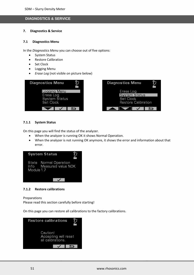
7.1 Diagnostics Menu In the Diagnostics Menu you can choose out of five options:
System Status
Restore Calibration
Set Clock
Logging Menu
Erase Log (not visible on picture below)
7.1.1 System Status On this page you will find the status of the analyzer.
When the analyzer is running OK it shows Normal Operation.
When the analyzer is not running OK anymore, it shows the error and information about that error.
7.1.2 Restore calibrations Preparations Please read this section carefully before starting! On this page you can restore all calibrations to the factory calibrations.

SDM – Slurry Density Meter
52 www.rhosonics.com
DIAGNOSTICS & SERVICE
Pay attention before pressing . When accepted, all settings, calibrations and configurations will be lost and reset to the factory settings. 7.1.3 Set clock and Date On these pages the Time and date can be set.
7.1.4 Logging and Settings for diagnostics & evaluation For trouble shooting this is the proper way to solve the problem:
1. Check System Status and inform Rhosonics / the Distributor 2. Save a log-file and analyzer settings and send them to Rhosonics / the Distributor 3. Restore factory settings, only when Rhosonics tells you to do so. *A log file is automatically started when the power is turned on.
For trouble shooting or for your own diagnostics evaluation, you can save a Log-file. When this Log-file is stored to the USB stick the settings from the analyzer will be stored as well. The settings from the analyzer can then be interpreted by the factory. The Logging Menu page has 2 functions:
The Sample time can be set. You can choose from the following Sample times 1, 2, 5, 10 or 30 Seconds, 1, 2, 5 or 10 Minutes. Keep in mind that the log file has room for 65535 entries.
By selecting Get data the log-date will be written to the USB-stick
CAUTION:
SDM – Slurry Density Meter
53 www.rhosonics.com
DIAGNOSTICS & SERVICE
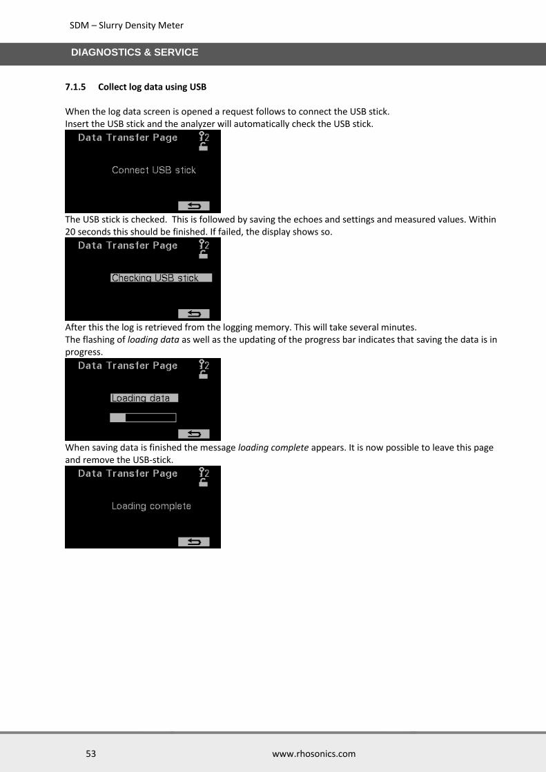
7.1.5 Collect log data using USB When the log data screen is opened a request follows to connect the USB stick. Insert the USB stick and the analyzer will automatically check the USB stick.
The USB stick is checked. This is followed by saving the echoes and settings and measured values. Within 20 seconds this should be finished. If failed, the display shows so.
After this the log is retrieved from the logging memory. This will take several minutes. The flashing of loading data as well as the updating of the progress bar indicates that saving the data is in progress.
When saving data is finished the message loading complete appears. It is now possible to leave this page and remove the USB-stick.

SDM – Slurry Density Meter
54 www.rhosonics.com
DIAGNOSTICS & SERVICE
The following files are now on the USB-stick: The file with the interface echo is starting with “I” followed by the date. In the below picture the Interface Echo file has the name “I160822.txt”. The name of the file contains information about year, month and day.
Following table gives an explanation about the filenames:
Filename Description
L”YYMMDD”.txt Log
C”YYMMDD”.txt Liquid echo (availability dependent on model)
E”YYMMDD”.txt Error/Status report
I”YYMMDD” .txt Interface echo
M”YYMMDD”.txt All measured values at time of “Get Log”
RLS-FILE.csv Liquid calibration in analyzer (Loadable for distributors)
S”YYMMDD”.txt Settings (Not loadable)
SETTING.csv Settings (Loadable for distributors)
7.1.6 Erase Log The device is permanently logging. This has the advantage that after an incidental measurement error the log can be retrieved. When a test is started there can be a desire to clear the data already present in the analyzer. Pressing to erase the log.

SDM – Slurry Density Meter
55 www.rhosonics.com
DISTRIBUTORS CALIBRATION (FOR RHOSONICS AND DISTRIBUTORS ONLY)
8. Distributors calibration (for Rhosonics and distributors only)
8.1 USB-port (only Distributors and Factory) The USB-port is used for:
Distributor calibrations using a PC via the service application.
Loading settings into the SDM
Loading Liquids into the SDM
Calibrations are model dependent. The following calibrations are present for every model.
mA trimming
Temperature These Factory calibrations can also be made by trained distributors.
Calibration page

SDM – Slurry Density Meter
56 www.rhosonics.com
DISTRIBUTORS CALIBRATION (FOR RHOSONICS AND DISTRIBUTORS ONLY)
8.2 mA trimming For mA trimming a calibrated mA meter is necessary. The SDM is calibrated at Rhosonics. A step by step instruction is given on the service application via several pop ups.
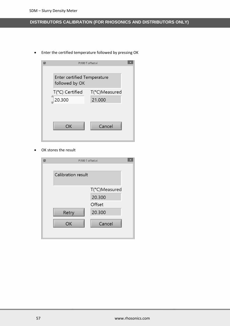
8.3 Temperature Check the temperature reading regularly, and perform a calibration when the reading error exceeds 5 ºC. It is advised to configure the set temperature with a calibrated sensor, as other temperature sensors in the same process may lack accuracy or may not be representative for the temperature at the installation location of the probe. The SDM doesn’t measure the temperature. The value for the offset is the temperature. The temperature for the SDM is actually a setting.
Press Temperature button
Press OK when the reference temperature is measured
SDM – Slurry Density Meter
57 www.rhosonics.com
DISTRIBUTORS CALIBRATION (FOR RHOSONICS AND DISTRIBUTORS ONLY)
Enter the certified temperature followed by pressing OK
OK stores the result
SDM – Slurry Density Meter
58 www.rhosonics.com
DISTRIBUTORS CALIBRATION (FOR RHOSONICS AND DISTRIBUTORS ONLY)
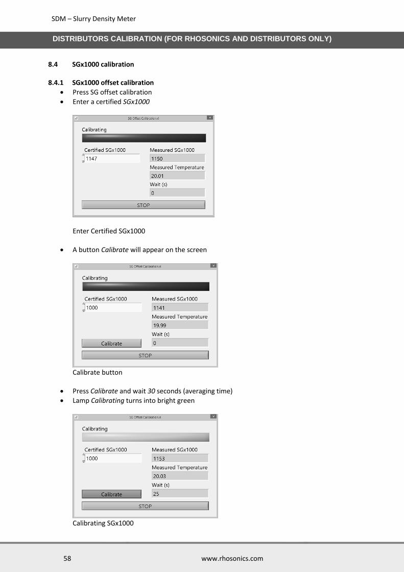
8.4 SGx1000 calibration 8.4.1 SGx1000 offset calibration
Press SG offset calibration
Enter a certified SGx1000
Enter Certified SGx1000
A button Calibrate will appear on the screen
Calibrate button
Press Calibrate and wait 30 seconds (averaging time)
Lamp Calibrating turns into bright green
Calibrating SGx1000

SDM – Slurry Density Meter
59 www.rhosonics.com
DISTRIBUTORS CALIBRATION (FOR RHOSONICS AND DISTRIBUTORS ONLY)
When the timer Wait(s) is 0 seconds the calibration is done, the Measured SGx1000 should be near the Certified SGx1000
8.4.2 SGx1000 span calibration The SGx1000 span calibration can be performed by 2 methods.
1 By entering the certified SGx1000. This should not be performed at the same SGx1000 as the offset calibration.
2 By changing the span factor. This can be performed at any current reading for SGx1000. The span factor changes the sensitivity for the SGx1000. If necessary it can be calculated by using the formula at the top of the calibration screen. In that case it is however easier just to enter the certified SGx1000 as is described in method 1.
SDM – Slurry Density Meter
60 www.rhosonics.com
TECHNICAL SPECIFICATIONS
9. Technical specifications
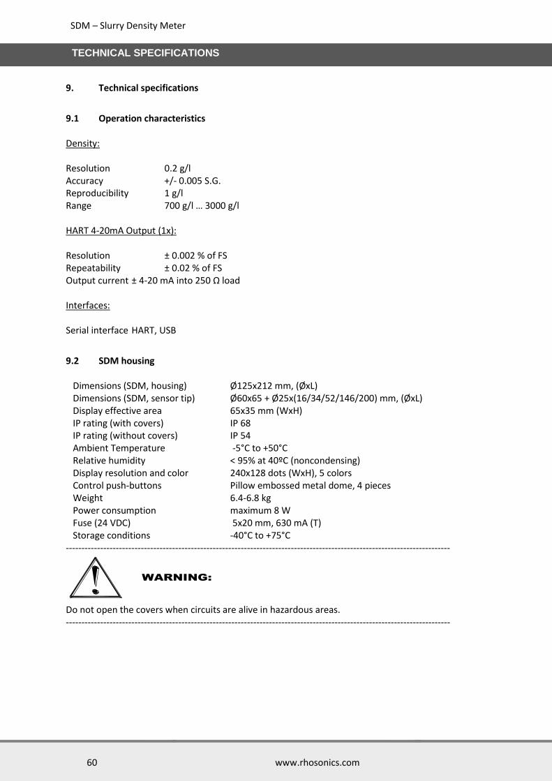
9.1 Operation characteristics Density: Resolution 0.2 g/l Accuracy +/- 0.005 S.G. Reproducibility 1 g/l Range 700 g/l … 3000 g/l HART 4-20mA Output (1x): Resolution ± 0.002 % of FS Repeatability ± 0.02 % of FS Output current ± 4-20 mA into 250 Ω load Interfaces: Serial interface HART, USB
9.2 SDM housing Dimensions (SDM, housing) Ø125x212 mm, (ØxL) Dimensions (SDM, sensor tip) Ø60x65 + Ø25x(16/34/52/146/200) mm, (ØxL) Display effective area 65x35 mm (WxH) IP rating (with covers) IP 68 IP rating (without covers) IP 54 Ambient Temperature -5°C to +50°C Relative humidity < 95% at 40ºC (noncondensing) Display resolution and color 240x128 dots (WxH), 5 colors Control push-buttons Pillow embossed metal dome, 4 pieces Weight 6.4-6.8 kg Power consumption maximum 8 W Fuse (24 VDC) 5x20 mm, 630 mA (T) Storage conditions -40°C to +75°C ---------------------------------------------------------------------------------------------------------------------------
Do not open the covers when circuits are alive in hazardous areas. ---------------------------------------------------------------------------------------------------------------------------
WARNING:

SDM – Slurry Density Meter
61 www.rhosonics.com
TECHNICAL SPECIFICATIONS
9.3 SDM sensor Wetted parts:
(Alloyed) Silicon nitride Si3N4
Duplex Steel ASTM/ASME: A240 UNS S32205/S31803
EURONORM: 1.4462 X2CrNiMoN 22.5.3
AFNOR: Z3 CrNi 22.05 AZ
DIN: W.Nr 1.4462
ISO: 4462-318-03-I
BS: 318S13
SS: 2377
JIS: SUS 329J3L
9.4 Spool / Weldolet / Wafer Specific dimensions:
Spool: Diameters up-to 30” (NW 750 mm)
Weldolet: o SDM-2 up to wall thickness 17 mm o SDM-3 wall thickness 17-39 mm
Wafer: Diameters up-to 60” (NW 1500 mm) Please contact Rhosonics for exact dimensions. All is depending on the pipe schedule and flange specifications.

SDM – Slurry Density Meter
62 www.rhosonics.com
APPENDICES
10. Appendices
10.1 List of spare parts
Fuses Ø5x20 mm, 630 mA, Slow, Art#: ZEPC-FUSE-T630MA-5X20
Sensor (incl. Seal ring), Art# : 3A0-322-043-A
Sensor (excl. Seal ring), Art#: 3A0-322-032-A
Seal ring, Art#: TRI-CLAMP-1½Z-ENVELOP
Clamp for sensor, Art#: TRI-CLAMP-HEAVY-1½Z
Cover front, Art#: 3A0-212-027-A (also fits on the back side)
Housing with electrical parts inside, Art#: 3A0-210-031-A
10.2 Options
Power supply/converter, 24VDC out, 90…264 VAC in, Art#: ZEAS-PS-24VDC-DNR18US24
HART to Modbus RTU converter, Art#: 9999-GATEWAY-GW-800-B
Service kit, Art#: 9D-SERVICE-KIT (contains USB-A male to USB-A male cable, 2 meter and Rhosonics software for service), Distributors only
10.3 Appendix A: Sound speed of water at 0 to 100 °C
T [°C] c [m/s] T [°C] c [m/s] T [°C] c [m/s] T [°C] c [m/s]
0 1402.388 25 1496.687 50 1542.551 75 1555.133 1 1407.367 26 1499.323 51 1543.619 76 1555.081 2 1412.232 27 1501.883 52 1544.636 77 1554.991 3 1416.985 28 1504.37 53 1545.601 78 1554.862 4 1421.628 29 1506.784 54 1546.517 79 1554.696 5 1426.162 30 1509.127 55 1547.382 80 1554.492 6 1430.589 31 1511.399 56 1548.199 81 1554.251 7 1434.912 32 1513.603 57 1548.967 82 1553.974 8 1439.132 33 1515.738 58 1549.687 83 1553.66 9 1443.251 34 1517.806 59 1550.36 84 1553.31 10 1447.27 35 1519.81 60 1550.986 85 1552.924 11 1451.191 36 1521.745 61 1551.566 86 1552.504 12 1455.016 37 1523.618 62 1552.101 87 1552.048 13 1458.747 38 1525.428 63 1552.59 88 1551.558 14 1462.384 39 1527.176 64 1553.035 89 1551.034 15 1465.931 40 1528.863 65 1553.437 90 1550.476 16 1469.387 41 1530.489 66 1553.794 91 1549.884 17 1472.755 42 1532.066 67 1554.109 92 1549.259 18 1476.036 43 1533.564 68 1554.381 93 1548.602 19 1479.231 44 1535.015 69 1554.611 94 1547.912 20 1482.343 45 1536.409 70 1554.799 95 1547.19 21 1485.372 46 1537.746 71 1554.947 96 1546.436 22 1488.319 47 1539.028 72 1555.053 97 1545.651 23 1491.187 48 1540.256 73 1555.12 98 1544.834 24 1493.976 49 1541.43 74 1555.146 99 1543.987 100 1543.109
Sound speed of water [m/s] at different temperatures [°C]

SDM – Slurry Density Meter
63 www.rhosonics.com
APPENDICES
10.4 Appendix B: Density of water at 0 to 100 °C
T [°C] RHO [g/l] T [°C] RHO [g/l] T [°C] RHO [g/l] T [°C] RHO [g/l]
0 999.86341 25 997.04784 50 988.00825 75 974.85658
1 999.91390 26 996.78615 51 987.55238 76 974.25961
2 999.94857 27 996.51495 52 987.09017 77 973.65750
3 999.96773 28 996.23442 53 986.62172 78 973.05025
4 999.9717 29 995.94474 54 986.14709 79 972.43790
5 999.96082 30 995.64608 55 985.66636 80 971.82046
6 999.93537 31 995.33859 56 985.17959 81 971.19794
7 999.89566 32 995.02246 57 984.68686 82 970.57037
8 999.84198 33 994.69781 58 984.18822 83 969.93776
9 999.77462 34 994.36483 59 983.68373 84 969.30013
10 999.69386 35 994.02363 60 983.17346 85 968.65748
11 999.59998 36 993.67438 61 982.65745 86 968.00984
12 999.49325 37 993.31720 62 982.13577 87 967.35721
13 999.37393 38 992.95224 63 981.60845 88 966.69961
14 999.24227 39 992.57962 64 981.07555 89 966.03705
15 999.09854 40 992.19946 65 980.53711 90 965.36954
16 998.94297 41 991.81189 66 979.99318 91 964.69708
17 998.77580 42 991.41702 67 979.44379 92 964.01969
18 998.59727 43 991.01497 68 978.88899 93 963.33739
19 998.40761 44 990.60585 69 978.32881 94 962.65017
20 998.20703 45 990.18976 70 977.76328 95 961.95804
21 997.99576 46 989.76681 71 977.19245 96 961.26103
22 997.77400 47 989.33709 72 976.61633 97 960.55912
23 997.54196 48 988.90070 73 976.03496 98 959.85235
24 997.29984 49 988.45772 74 975.44837 99 959.14070
100 958.42421
Density of water [g/l or kg/m3] at different temperatures [°C]

SDM – Slurry Density Meter
64 www.rhosonics.com
APPENDICES
10.5 Appendix C: Flow DD (HART)

SDM – Slurry Density Meter
65 www.rhosonics.com
ABOUT US
Headquarters
Distributors
MEASURING BEYOND LIMITS At Rhosonics, we continuously work on improving our analysers and sensors. We believe that we can offer solutions for almost any application. We can help you by adapting our solutions to improve your production processes, together with our worldwide network of distributors.
CONTACT US Rhosonics Analytical B.V. Hoge Eng West 30 3882 TR Putten, The Netherlands Phone: +31 341 – 37 00 73 Email: [email protected] Website: www.rhosonics.nl