sdio as a new peripheral attack vector - de laat · sdio as a new peripheral attack vector ......
TRANSCRIPT

University of Amsterdam
MSc System and Network Engineering
Research Project 2
SDIO as a new peripheralattack vector
Authors:
Thom [email protected]
Dana [email protected]
Supervisor:
Cedric Van Bockhaven
August 1, 2016

Abstract
SDIO peripherals are used to extend the capabilities of SDIO aware hosts. Inorder to connect peripherals to hosts, SDIO uses a universal bus in a similar fashionas USB does. In 2014 a new attack exploiting the universality of USB, known asBadUSB, was demonstrated. As SDIO presents similarities with USB, an attackthrough SDIO might be possible. Our research explores SDIO as an attack vectorand shows that it could be used to exploit SDIO aware hosts. Hence, presentinga new attack vector on devices such as laptops, tablets and PDAs. Our researchcomprises several phases. We start by performing an in-depth analysis of the SDIOstandard to gain knowledge about its protocols and requirements. We then examinethe communication between SDIO peripherals and SDIO aware hosts. Based onthe results of the latter phase, we define potential attack paths and determineprerequisites for an attack to be successful. Finally, we present two methods fordeveloping a malicious SDIO peripheral to exploit SDIO aware hosts.

Acknowledgements
Our special thanks go to our supervisor Cedric Van Bockhaven, for the receivedguidance and feedback throughout the project. In addition, we would like to thankDeloitte Risk Services for making this research possible, and for providing us withmaterials needed to conduct our experiments. We would also like to thank MickPouw for his advice on hardware devices. Finally, the SD card image of the frontpage was extracted from [1].
Contents
1 Introduction 11.1 Research Questions . . . . . . . . . . . . . . . . . . . . . . . . . . . . 11.2 Related Work . . . . . . . . . . . . . . . . . . . . . . . . . . . . . . . 11.3 Scope . . . . . . . . . . . . . . . . . . . . . . . . . . . . . . . . . . . 21.4 Testbed . . . . . . . . . . . . . . . . . . . . . . . . . . . . . . . . . . 21.5 Report Structure . . . . . . . . . . . . . . . . . . . . . . . . . . . . . 3
2 Methodology 4
3 Attack Scenarios 53.1 Rogue DHCP Server . . . . . . . . . . . . . . . . . . . . . . . . . . . 53.2 Keystroke Injection . . . . . . . . . . . . . . . . . . . . . . . . . . . . 6
4 SDIO 84.1 SDIO Stack . . . . . . . . . . . . . . . . . . . . . . . . . . . . . . . . 10
4.1.1 Physical Layer: SPI and SD . . . . . . . . . . . . . . . . . . . 114.1.2 SDIO Layer . . . . . . . . . . . . . . . . . . . . . . . . . . . . 124.1.3 Business Logic Layer . . . . . . . . . . . . . . . . . . . . . . . 12
5 General Host-Peripheral Model Based on the SDIO Stack 13
6 SDIO Hosts 146.1 Analysis Methods . . . . . . . . . . . . . . . . . . . . . . . . . . . . . 146.2 SDIO Aware Hosts . . . . . . . . . . . . . . . . . . . . . . . . . . . . 14
6.2.1 Requirements for Hosts Equipped with an SDIO Slot . . . . . 156.2.2 Requirements for Hosts that Implement SDIO Through GPIO 16
7 SDIO Peripherals 17
8 Host System Exploitation 188.1 Develop an SDIO Peripheral and Create New Firmware . . . . . . . 18
8.1.1 Develop an SDIO Peripheral Using the SPI Protocol . . . . . 188.1.2 Develop an SDIO Peripheral Using the SD Protocol . . . . . 19
8.2 Modify Existing Firmware . . . . . . . . . . . . . . . . . . . . . . . . 20
9 Evaluating SDIO Attacks 239.1 Creating New Firmware vs. Modifying Existing Firmware . . . . . . 239.2 Using the SD Protocol vs. Using the SPI Protocol . . . . . . . . . . 239.3 SDIO vs. USB Attacks . . . . . . . . . . . . . . . . . . . . . . . . . . 23
10 Discussion 25
11 Conclusion 26
12 Mitigations 27
13 Ethical Considerations 28
14 Future Work 29
15 References 30
Appendix A Acronyms 33
Appendix B Raspberry Pi SDIO Pinout 34
Appendix C Logic Sniffer Captures 34
Appendix D Firmware Entropy 36

1 Introduction 1
1 Introduction
SDIO (Secure Digital Input Output) is an extension to the SD (Secure Digital)specification maintained by the SD Association to cover I/O functions [2]. It may beused by compliant devices, such as PDAs and laptops, to extend their capabilities.Among others, these capabilities include Bluetooth, GPS, camera and WLAN.
In 2014 a new attack exploiting the universality of USB, known as BadUSB, wasdemonstrated by Karsten Nohl and Jakob Lell [3]. They showed that firmware isoften not signed by USB vendors, thus it can subsequently be rewritten for maliciousintent: self-replicating viruses, command injection and rogue DHCP servers wereamong the demonstrated attacks. As these ‘BadUSB’ devices have the appearanceof a regular USB storage device, an unwitting user may wrongly perceive the deviceas innocuous and subsequently insert it into a host system.
Analogous to USB, SDIO is a universal bus that can be used by a variety ofperipherals. The universality of SDIO poses a potential risk similarly to USB.Despite the impact of BadUSB in computer security, and its apparent similaritieswith SDIO, SDIO seems not to be perceived as an attack vector thus far.
In this report we research SDIO as a new peripheral attack vector. We will eval-uate on the feasibility of SDIO-based attacks and discuss their potential impact.
1.1 Research Questions
In this report, the following research question will be answered: Could SDIO beused as a new attack vector on SDIO aware hosts?
In order to answer this question adequately, we focused on the following sub-questions:
• What are the characteristics of an ‘SDIO aware’ host?
• What communication protocols are supported by SDIO peripherals?
• What malicious interactions could be performed on an SDIO aware host?
• How could a malicious SDIO peripheral be developed?
• What are the similarities and differences between SDIO and USB from asecurity perspective?
1.2 Related Work
In BadUSB - On Accessories that Turn Evil Karsten Nohl and Jakob Lelldemonstrated how firmware of USB devices could be rewritten for malicious in-tent [3]. They showed how malicious USB devices can reconfigure hosts’ networksettings, inject keystrokes and spread self-replicating viruses.
Moreover, they conclude that many other USB capabilities are potentially ex-ploitable. Analogous to USB, SDIO is a universal bus that can be used by a varietyof peripherals. The universality of SDIO poses a potential risk similarly to USB.
In Exploration and Exploitation of an SD Memory Card Andrew Huang andSean Cross demonstrate that firmware of microSD cards can be rewritten to per-form arbitrary code execution on the peripheral itself. They succeeded in reverseengineering the firmware a specific microSD card from a testbed of many [4]. Theywere able to reverse engineer most of the microcontroller’s specific functions, en-abling them to develop novel applications for the controller [5].

1 Introduction 2
Despite performing a MitM attack on the flash memory, their research does notencompass attacks against the host machine nor does it cover SDIO-based attacks.
In A Microcontroller-based HF-RFID Reader Implementation for the SD-SlotAndreas Loeffler and Andreas Deisinger describe an RFID reader system based onan emulated file system to be used in SD-capable systems [6]. They developed aprototype that could interact with applications on the host through its SD slot,by means of the SD protocol. However, in contrast to the adoption of SDIO, theirwork shows an approach that utilises SD storage only.
1.3 Scope
In this report we research the capabilities of SDIO as a new peripheral attackvector. The attack described in this report is considered to apply to SDIO awarehosts assuming the presence of the required drivers. This includes compliant PDAsand laptops among other devices.
The main focus of the research will be on Linux hosts. Publicly available infor-mation about SDIO is limited for all operating systems, which introduces difficul-ties in preliminary research. Open source operating systems (e.g. Linux) allow forsource code modification, which eases experimental tasks such as kernel and driverdebugging.
During our research we focused on generic SDIO and SDIO WLAN drivers.WLAN seems to be the most prevalent application of SDIO and is expected to begenerally incorporated in SDIO aware hosts. Moreover, WLAN is a standardisedSDIO interface included in the SD specifications in the Wireless LAN SimplifiedAddendum document [7]. This might allow for a malicious SDIO WLAN card tointeract with a variety of WLAN drivers.
Despite this focus, our research is not limited to WLAN over SDIO. The re-sults and principles discussed can be applied to other SDIO capabilities, such asBluetooth and GPS.
1.4 Testbed
Our experiments were conducted on an HP EliteBook 840 G1 laptop incorporat-ing an SDIO compliant card reader and a Raspberry Pi 2 Model B exposing SDIOpins. We loaded the laptop with Ubuntu 16.04 to accommodate driver debuggingwhile the Raspberry Pi was loaded with Raspbian Jessie 8.
The SDIO WLAN adapters ATWILC1000-SD from Atmel Corporation [8] andESP8266 from Espressif Systems [9] were used in our experimentation.
The ESP8266 differs from the ATWILC-1000 as it does not have the SDIO cardform factor. This means it needs to connect to a host’s SDIO bus via its pins. Boththe ATWILC1000-SD and the ESP8266 peripherals are shown in Figure 1.
The ATWILC-1000 loads its firmware from the host as it does not have non-volatile storage to store it. In contrast, the ESP8266 allows for two different waysof loading firmware. One of the options is loading firmware from the host (viaSDIO for example). However, the default method used in this device consists ofloading the firmware that is located in the flash chip it incorporates.
The ESP8266 does not normally expose its SDIO pins, as it uses them to loadits firmware from the flash chip. Therefore, we desoldered the flash chip to exposethese SDIO pins. This allowed us to connect the device to the host’s SDIO bus,and be able to load firmware on the device from the host by means of SDIO.

1 Introduction 3
For firmware analysis we investigated the Wilc1000 firmware used in ATWILC-1000 peripherals and the SD8686 V9 firmware used in Marvell Libertas 88W8686microcontrollers [10].
Fig. 1: ATWILC1000-SD (top) and ESP8266 (bottom)
1.5 Report Structure
We start by describing the methodology used for conducting the research inChapter 2. In Chapter 3, we discuss two attack scenarios and illustrate the potentialimpact of SDIO-based attacks.
We continue by analysing the SDIO protocol and elaborate on its details inChapter 4. This chapter explores SDIO inner workings, relevant components andunderlying communication protocols.
Chapter 5 presents a summary of the key components for both SDIO hostsand SDIO peripherals. In Chapters 6 and 7 we elaborate on SDIO hosts andSDIO peripherals respectively. We describe how hosts and peripherals interact andelaborate on system requirements for successful exploitation.
In Chapter 8 we describe two approaches in developing a malicious SDIO pe-ripheral. We also discuss enabling technologies for developing these peripherals.
Chapter 9 evaluates SDIO-based attacks taking into account different dimen-sions. In Chapters 10, 11 and 12 we discuss our results, answer our research ques-tions and provide recommendations to mitigate SDIO-based attacks.
Finally, in Chapters 13 and 14 we describe our ethical considerations and pro-pose future work based on our results.
2 Methodology 4
2 Methodology
This methodology outlines the course of our research, which is divided intoseveral phases. In the first phase we researched several scenarios in which SDIOcould be used as an attack vector. We then examined the relevant specificationsprovided by the SD Association to understand the SDIO standard. In this context,communication protocols described by the Physical Layer Specification [11] suchas SPI and SD, and higher-level specifications like WLAN [7] were explored. Thisallowed us to have a more comprehensive understanding of how SDIO peripheralsare constituted and to understand their internal operation.
In the second phase, we focused on the host-peripheral interaction. We first cre-ated a high level model that illustrates the components of both host and peripheralon a per layer basis. The model was used to further revise SDIO attack scenarios.We then modified the host’s kernel modules to include debugging statements. Thisallowed us to determine the requirements of the host when interacting with SDIOperipherals.
In the last phase, we identified two approaches for developing a malicious SDIOperipheral in order to exploit SDIO drivers on the host. The first approach in-volves designing and building a new SDIO peripheral. The second approach takesadvantage of an existing SDIO peripheral and aims at modifying its firmware. Toassess the feasibility of the second approach we examined the firmwares’ entropyin order to detect encryption. For this purpose we used the Linux applications Entand Binwalk. In addition, we inspected enabling technologies and techniques fordeploying both approaches.
3 Attack Scenarios 5
3 Attack Scenarios
This research studies whether the universality of SDIO could be exploited in asimilar fashion as BadUSB. In this sense, no application vulnerability on the hostitself will be exploited. The objective of this attack is to exploit an unmodified hostusing legitimate interaction with a malicious SDIO peripheral. In this context, theperipheral will interact with legitimate drivers on the host and misuse them forulterior purposes. Each interaction is perceived as legitimate by the host, yet un-intended by the user. The attack focuses on the interactions between the firmwareof the SDIO peripheral (which is modified for malicious intent), and the genuinedrivers installed on the host.
An SDIO compliant host incorporates a general purpose SDIO connector, whichis intended to handle a range of capabilities as defined by the SD Association.SDIO peripherals with different capabilities may be plugged into a universal SDIOconnector. Host systems probe the peripheral to load the corresponding manufac-turer’s drivers. This inherent characteristic of SDIO gives an adversary flexibility,as a malicious peripheral may identify itself as any other peripheral offering legiti-mate functionality. Moreover, no security measures enabling the host to verify theauthenticity of the peripheral seem to exist.
Each SDIO capability (e.g. WLAN, Bluetooth, GPS) increases the attack sur-face, as higher-level applications on the host base decisions on information origi-nating from SDIO peripherals. Sections 3.1 and 3.2 describe the exploitation oftwo capabilities, WLAN and Bluetooth respectively.
Throughout this report, we consider a peripheral that identifies itself as a le-gitimate SDIO peripheral, yet concealing functionality that might harm the hostsystem, as malicious.
3.1 Rogue DHCP Server
In this scenario an SDIO peripheral replies with a malicious DHCPOFFER tothe host’s DHCPDISCOVER message. The peripheral may reply with multipleDHCP Options, one of which is DHCP option 6 for DNS servers. When exploited,the host will be configured to use the DNS server specified in the DHCPOFFERmessage. The DNS server is also malicious and provides forged IP addresses forlooked up hostnames.
When the host performs a DNS lookup of a hostname, the response from theDNS server will include a forged IP. A connection will then be made from thehost to that IP address instead of the genuine IP address. This attack targets allcommunication that relies on hostnames, such as web and e-mail.
Figure 2 illustrates this scenario. When the malicious WLAN peripheral isinserted into the host, the host requests its network configuration through DHCP.The peripheral configures the host to use a malicious DNS server (e.g. 9.9.9.9).Consequently, when the host looks up a web page (e.g. bank.os3.nl), it will connectto a web server maintained by the adversary. This can be used to obtain sensitiveinformation such as credentials.
We identified two approaches in performing this attack. In the first approach,an SDIO WLAN peripheral is used to act as a WiFi adapter (which is the defaultfunctionality for such an SDIO device). The firmware of the SDIO peripheral isthen extended to add more functionality. In this situation, the peripheral emulatesthe underlying infrastructure to configure a host’s network settings (e.g. an APand DCHP server). This way, when the SDIO peripheral is connected to the host,

3 Attack Scenarios 6
Fig. 2: Rogue DHCP Server through SDIO WLAN Card
it does not only present a WiFi adapter but also the connection made with the fakeAP it is emulating. The host will start interacting with the emulated components asif they were on a physical network. This allows the malicious DHCP server (beingemulated by the peripheral), to configure the host to use a DNS server under thecontrol of the adversary, instead of a legitimate one. This approach allows theadversary to exploit an existing network connection (e.g. Ethernet) without theneed of connecting the peripheral to a real network, as this will be emulated by themalicious peripheral’s software.
In the second approach, the SDIO peripheral is an actual WiFi adapter, onlymodified to intercept and alter certain network packets, such as DHCPOFFERmessages. This approach does not require the adversary to emulate an infrastruc-ture, as it is using an existing one. However, the peripheral needs to be connectedto an AP which might be less feasible to exploit.
Targeting a host’s network configuration through SDIO is appealing for severalreasons. First of all, WLAN is a common capability of SDIO peripherals. MostSDIO kernel modules are developed for WLAN peripherals, which increases thehost’s attack surface. Secondly, network settings are configured by daemons inthe background. An unwitting user may be unaware of any malicious action bythe peripheral. Thirdly, an adversary may serve forged IP addresses for a rangeof hostnames, while serving genuine IP addresses for others. This will cause thenetwork to function normally from the user’s perspective for many cases, makingthe attack more difficult to detect.
3.2 Keystroke Injection
In this scenario a keyboard is emulated by the peripheral to execute arbitrarycommands. While the SD Association does not standardise an SDIO keyboardinterface, it does specify a Bluetooth interface. Consequently, any device that usesBluetooth could be emulated, including Bluetooth keyboards and mice.
Moreover, different Bluetooth peripherals may be emulated sequentially. This

3 Attack Scenarios 7
might be used to navigate the mouse to open an application and subsequently injectkeystrokes.
Depending on the emulated device, Bluetooth attacks might be more obtrusiveas compared to attacks described in the previous section (Section 3.1). The usermay notice unusual behaviour, such as a moving mouse or commands appearing onthe terminal. Moreover, connected Bluetooth devices are shown in the (graphical)interface of operating systems such as Windows and Ubuntu.
Karsten Nohl and Jakob Lell demonstrated the impact of keystroke injectionusing USB. They used this technique to spawn a Meterpreter shell and spreadself-replicating viruses on a host system, without alarming any virus scanners [3].

4 SDIO 8
4 SDIO
SDIO (Secure Digital Input Output) is an extension of the SD specification toinclude I/O functions [2]. The SDIO specification defines requirements that SDIOperipherals should comply with to provide hosts with capabilities such as Blue-tooth, GPS and WLAN. Figure 3 shows a more comprehensive set of capabilitiesas envisioned by the SD Association.
Fig. 3: SDIO Card Types [12]
SDIO and SD storage have the same physical specification; they use the samepinout and bus to communicate with hosts. Distinctions are made in the protocol asSDIO peripherals may implement and respond differently to certain commands ascompared to SD storage devices. Details regarding SDIO peripherals are discussedin Chapter 7.
The SDIO specification encompasses three different SD card form factors:
• Full Size SDIO: compatible with host sockets designed for SD memorycards.
• Mini SDIO: compatible with host sockets designed for miniSD memorycards.
• Micro SDIO: compatible with host sockets designed for microSD memorycards.
Compatibility with a specific form factor differs per host. For instance, FullSize SDIO is supported by HP EliteBook 840 G1 laptops, while Micro SDIO issupported by the Opticon H21 PDA and Mini SDIO is supported by the H16 [13][14].
The specification describes physical properties of each form factor such as ap-pearance and pinout. The SDIO protocol is loosely coupled with these form factorsso it remains the same among all of them.

4 SDIO 9
Figure 4 shows the pins of a Full Size SDIO memory card.
Fig. 4: SD Memory Card Shape and Interface (modified from [11])
The SDIO specification defines two card types:
• SDIO Card: this card incorporates an I/O controller only.
• Combo Card: this card incorporates an I/O and Memory controller.
SDIO cards may implement any SDIO capability, while combo cards may imple-ment any SDIO capability and provide SD storage as well. In addition, combocards may be used as an SDIO only or SD Memory only card after initialisation.
SD storage peripherals such as the Transcend TS16GWSDHC10 card [15], pro-vide a WiFi hotspot to connect with and access its storage wirelessly through a webinterface. Applications on these peripherals (e.g. web interface) may contain arbi-trary code execution vulnerabilities [16], which may seemingly be used to exploitits SD interface and perform attacks on hosts systems. However, peripherals assuch do not implement SDIO to provide a wireless hotspot. They use a hardwaremodule capable of providing this functionality independently of the host and onlyuse the SD(IO) pins for power supply.
SDIO cards can only function if the host system supports their I/O functions,which is the case for several PDAs [17]. However, currently there are a numberof SDIO compliant hosts other than PDAs. Ubiquitous hosts, such as laptopsand tablets, can also be equipped with SDIO slots. While other devices, such asRaspberry Pi boards, use GPIO pins to provide an SDIO interface. Appendix Bshows the pinout for GPIO as an interface to SDIO for the Raspberry Pi 2.
The SD Association provides a simplified version of the SDIO specification to beused without a license [2]. However, a license is required for the complete specifica-tion, which comprises more details about commands, data formats and interruptsused in SDIO implementations. Our research is based on publicly available infor-mation such as the simplified specifications provided by the SD Association, aswe did not obtain a license for any of the specifications mentioned throughout thereport.
Moreover, the SDIO specification relies on other specifications maintained bythe SD Association. Figure 5 shows these related specifications. An example is thePhysical Layer Specification [11] which provides implementation details on regularSD memory cards, as well as mandatory communication protocols.

4 SDIO 10
Fig. 5: SDIO Related Specifications [2]
4.1 SDIO Stack
As aforementioned, limited information regarding SDIO is available. This ob-structs preliminary research as there is no general overview of compliancy. Toillustrate how the SDIO standard is constituted, we developed a model based onavailable information in the specifications. This SDIO Stack model presents threedifferent layers, each of them providing a higher level of abstraction as they stack.The model is displayed in Figure 6.
The lowest layer of the stack represents the physical layer of SDIO. It is re-sponsible for handling low level details such as supported voltage ranges and bittransfer modes [11]. The second layer handles the SDIO protocol in itself, definingthe commands available for I/O functions and communication patterns such as ini-tialisation sequences [2]. Finally, the business logic layer implements any capabilitythat SDIO may provide. This includes a variety of capabilities as shown in Figure3, one example being the WLAN capability [7]. Each of the layers will be explainedin more detail in Subsections 4.1.1, 4.1.2 and 4.1.3 respectively.
Fig. 6: SDIO Stack

4 SDIO 11
4.1.1 Physical Layer: SPI and SD
This layer defines two bus protocols, which are mandatory for SD cards ac-cording to the Physical Layer Specification [11]. These are the SD and the SPIprotocols. Table 1 shows how the pins of an SD(IO) card are used by the linesdefined in each protocol. Both protocols account for voltage, ground, clock anddata lines.
Tab. 1: SD and SPI lines
Pin # SD Mode SPI ModeName Description Name Description
1 CD/DAT3Card Detect/Data Line [Bit 3]
CS Chip Select
2 CMD Command/Response SDI Data In3 VSS1 Supply voltage ground VSS Supply voltage ground4 VDD Supply voltage VDD Supply voltage5 CLK Clock SCLK Clock6 VSS2 Supply voltage ground VSS2 Supply voltage ground7 DAT0 Data Line [Bit 0] SDO Data Out8 DAT1 Data Line [Bit 1] RSV Not used9 DAT2 Data Line [Bit 2] RSV Not used
SPI is a well-known open protocol, utilised in a variety of applications servingas an interface to a considerable number of peripherals such as sensors [18] andLCDs [19]. It is simple and it only accounts for the use of a single data line (theSDI line to receive data from an SDIO host and SDO to send data to the host).
In contrast to SPI, SD is not as widely used as SPI. SD is only used in ap-plications aimed at interacting with SD cards, which makes it less pervasive. Inaddition, SD is more complex and its full specification requires licensing. Morecommands and multiple operation modes are specified as part of SD, which dependon the data lines being used. These are known as 1-bit (DAT0) and 4-bit (DAT0,DAT1, DAT2 and DAT3) SD bus modes. By using concurrent data streams, thelatter may achieve higher transfer rates.
One of the most relevant differences between SPI and SD is that SD is thedefault bus protocol used by SDIO cards. In this context, SPI functions as afall-back mechanism which the card can use if the host decides to do so.
The specification describes the communication flow between the SDIO periph-eral and the host system by defining a set of commands, responses and data blocksfor each protocol.
A command is a token used to start an operation, and is sent from the hostto the SDIO peripheral. A response is a token that the SDIO peripheral sendsto the host to answer a previously received command. The data blocks, are usedto exchange data from the peripheral to the host and vice versa. Figures 7 and 8illustrate the communication flow within a single block read transfer for SD andSPI respectively.

4 SDIO 12
Fig. 7: Single Block Read Transfer, SD Mode [20]
Fig. 8: Single Block Read Transfer, SPI Mode [20]
4.1.2 SDIO Layer
The SDIO specification defines that both SPI and SD are mandatory for SDIOperipherals as its underlying communication protocols. It adds SDIO functionalityby defining new commands and responses to the existing SD protocol and it alsopresents a different initialisation sequence and additional error conditions.
As inherited by its underlying communication protocols, SDIO is a Master-Slaveprotocol. The master (host) decides what communication protocol to use and sendscommands to which the slave (peripheral) must reply in a timely manner.
4.1.3 Business Logic Layer
The Business Logic Layer implements the functionality that the SDIO periph-eral provides. To fulfil this purpose, it uses the commands and responses defined inthe SDIO Layer. Some of these capabilities, such as WLAN, Bluetooth and GPSare standardised, while others like Ethernet and Fingerprint Recognition are not.
This layer is especially relevant to manufacturers who implement the function-ality they want to provide in their SDIO peripherals. Business logic needs to beimplemented on both the peripheral and the host. The peripheral implements thisas its firmware, while the host implements the corresponding drivers. Chapters 5,6 and 7 elaborate on drivers, firmware and their interactions.

5 General Host-Peripheral Model Based on the SDIO Stack 13
5 General Host-Peripheral Model Based on the SDIO Stack
This chapter gives a high level description of the way both SDIO aware hostsand SDIO peripherals implement the SDIO Stack introduced in Chapter 4. Figure9 shows the complete model we developed for this purpose. In this model the layersof the host and the peripheral are depicted colour coded according to the place theyoccupy in the SDIO Stack.
On the peripheral, the physical layer is handled by its microcontroller. It im-plements both the SPI and the SD bus protocols, deemed mandatory by the SDIOspecification. The layers corresponding to SDIO and Business Logic of the SDIOStack are implemented in firmware.
On the host, the physical layer is handled by the microcontroller present onthe card reader, which implements the SD bus (and optionally implements the SPIbus). The top two layers are comprised of drivers that interact with the card’sfirmware. When a peripheral is inserted, the generic OS drivers read the card’sinformation. Subsequently, control of the peripheral is passed to its correspondingmanufacturer drivers.
Chapters 6 and 7 provide a more detailed explanation of how these layers areimplemented and discusses the interactions that take place between the host andthe peripheral.
Fig. 9: Host-Peripheral Model Based on the SDIO Stack
6 SDIO Hosts 14
6 SDIO Hosts
The SDIO Specification introduces the term SDIO aware host. However, it doesnot elaborate on requirements a host needs to comply with to be categorised assuch.
The SD Host Controller Specification [21] describes implementation guidelinesfor SD(IO) hosts. It includes guidelines for card readers, OS supplied drivers andvendor specific drivers. However, adherence to this specification is not mandatory.It therefore does not define the requirements of an SDIO aware host.
An understanding of the actual requirements needed for a host to be consideredSDIO aware is crucial to our research as it affects the attack surface and thereforethe probability of actual exploitation. In addition, it influences considerations thatmight need to be taken into account when outlining an attack scenario.
To determine what is considered SDIO aware, we analysed the interactionsthat take place between a host and a peripheral. In Section 6.1 we elaborate onthe methods used for this purpose.
In Section 6.2 we discuss the prerequisites for SDIO aware hosts to supportSDIO peripherals.
6.1 Analysis Methods
Despite Linux being a well-known open source operating system, there is noclear documentation on how the SDIO drivers interact with SDIO peripherals. Weused several methods to examine how this interaction occurs.
By analysing the Linux kernel source code [22], it was discovered that the Linuxkernel contains generic drivers as well as manufacturer specific drivers to handleSDIO peripherals. We determined the relationships and identified the flow of con-trol between drivers that handle SDIO peripherals.
By adding debugging statements to kernel modules, we were able to verify theresults from the previous method and follow the flow of control more precisely.
By monitoring how kernel modules are being loaded, we discovered what mod-ules are used for what peripheral. We determined what modules were loaded atboot time and monitored changes that occurred in /proc/modules when SDIO pe-ripherals were inserted or removed.
We also monitored system buses to determine the system bus used by SDIOperipherals. We observed the /sys/bus/ system folder, and its relevant sub folders(/sys/bus/spi/devices, /sys/bus/mmc/devices, /sys/bus/sdio/devices). StandardSD peripherals are connected to the mmc system bus, while SDIO peripherals areconnected to the sdio system bus.
Finally, we introduced modifications to the kernel’s drivers to try to force theLinux operating system to use the SPI protocol by default. However, this attemptfailed. Furthermore, we found out that many modern microcontrollers do notsupport SPI and only support SD. The aforementioned fact makes this attemptless relevant as the protocol needs to be supported by both the microcontroller andthe drivers for the communication with the SDIO peripheral to be effective.
6.2 SDIO Aware Hosts
SDIO aware hosts require hardware and software components to handle SDIOperipherals. Hardware components are essential for interfacing with SDIO pro-tocols that operate on the physical layer of the SDIO Stack (SD and/or SPI).

6 SDIO Hosts 15
Software components, such as drivers, are required for interacting with the periph-erals’ firmware. Subsection 6.2.1 describes the requirements for hosts which areequipped with SDIO slots. Subsection 6.2.2 presents the prerequisites for hostswhich do not have SDIO slots, but use GPIO pins to provide SDIO capabilitiessuch as Raspberry Pi boards. Their main difference is the type of connector theyuse to interface with SDIO peripherals.
6.2.1 Requirements for Hosts Equipped with an SDIO Slot
One requirement an SDIO aware host has, is to be equipped with a micro-controller capable of handling SDIO’s underlying communication protocols thatoperate on the physical layer of the SDIO Stack. The microcontroller plays a keyrole as it is the master in the communication with the SDIO peripheral.
SDIO compliant peripherals are required to implement both communicationprotocols (SD and SPI). However, SDIO aware hosts seemingly do not share thisrequirement. Modern SD card readers may support the SD protocol only, as SPIis considered to be a low-cost alternative with lower data transfer rates.
Over the low-level components such as microcontrollers, card reader drivers(specific to each manufacturer) are used to monitor the system bus to detect anyevents. When an SDIO peripheral is connected to the host, these low-level driverspass control to the generic drivers for further interaction. Their source code islocated in the drivers/mmc/host folder of the Linux kernel source code tree. Anexample of such a driver is the rtsx pci sdmmc which interacts with the RealtekSemiconductor Co., Ltd. RTS5227 PCI Express Card Reader [23].
Generic drivers interact with the SDIO peripheral to probe for the type, manu-facturer and product. In addition, they handle generic SD and SDIO errors such asincompatible voltages. They facilitate in loading the corresponding SDIO periph-eral manufacturer drivers and pass control accordingly. The source code of thesedrivers is located in the drivers/mmc folder within the Linux kernel source tree.
After identification by the generic drivers, control is passed to the manufacturerdrivers. These drivers are used to interact with the business logic implemented inthe card’s firmware. Their source code is placed in different kernel folders accordingto their SDIO capability. For instance, the libertas sdio driver used for handlingMarvell WLAN microcontrollers is placed in drivers/net/wireless/marvell/libertas.If the manufacturer drivers are not present on the host system, the SDIO peripheralwill presumably not operate. The Linux source code and SDIO specifications donot indicate the existence of any other (generic) drivers that could take over thetask of handling SDIO peripheral’s firmware implementing the business logic.
To illustrate how the drivers operate and interact, we propose the three layerdriver scheme displayed in Figure 10. Applications using information provided bythese drivers are not shown in this diagram.
The lowest layer corresponds to the ”Card Reader Drivers” which are the specificdrivers for the card reader on the host. They monitor the system bus and detectevents, such as a peripheral being plugged in the SDIO slot. They subsequentlymake a call to the ”Generic OS Drivers”. The latter probe the card to identifyinformation such as type, manufacturer, product and operating voltage levels. Oncethe SDIO card is considered ‘valid’, ”Manufacturer Drivers” are invoked to handlethe SDIO specific functionality.
For SDIO peripherals to work as intended by the manufacturers, the host needsaccess to the corresponding drivers to handle the peripheral. One way is for the

6 SDIO Hosts 16
Fig. 10: SDIO Aware Host Drivers
host to have the drivers installed and loaded as kernel modules. The kernel loadsthese modules automatically as soon as the peripheral is connected.
As the kernel detects a new peripheral, it uses modprobe for device probing.Modprobe identifies the modules corresponding to the SDIO peripheral, and loadsthem accordingly. A similar process takes place at boot time. Upon booting,the kernel enumerates all hardware devices to load drivers for peripherals that arepresent.
It is important to note that drivers that are in development (staging), are notloaded automatically by modprobe and need to be loaded manually. An exampleof such a driver is the wilc1000 which is used to handle ATWILC1000-SD SDIOcapable peripheral.
The other way the host can get access to the drivers is by means of the CodeStorage Area (CSA). The CSA is a memory area in SDIO cards, which can be usedto store drivers on the peripherals. This mechanism facilitates the Plug-and-Playconcept for SDIO cards, as it lets manufacturers include drivers for different hostplatforms [2].
6.2.2 Requirements for Hosts that Implement SDIO Through GPIO
An example of a host that can interact with SDIO peripherals through GPIOpins is the Raspberry Pi 2 board. This device has two card controllers. One of themis used to handle the regular SD card that it uses to boot the operating systemfrom, through the SD card reader slot. The other can be used to interact with anSDIO peripheral through GPIO pins.
Driver collaboration occurs in a similar fashion as described for hosts equippedwith an SDIO slot as Raspberry Pi boards run a Linux kernel. A difference couldbe the specific card reader driver that picks up the events on the system bus, asthis depends on the card reader present in the Rapsberry Pi.
In 2015, Elliot Williams added WiFi capabilities to a Raspberry Pi 2 by usingthe ESP8266 IoT chip through SDIO [24]. His work illustrates how SDIO can beleveraged to provide additional capabilities to an SDIO aware host by connectingthe SDIO peripheral to its GPIO pins.

7 SDIO Peripherals 17
7 SDIO Peripherals
SDIO communication occurs in a master-slave fashion where the host is themaster and the SDIO peripheral is the slave. Linux-driven hosts are designed tobe the master as their drivers implement master logic. Making them behave likeslaves would require substantial changes such as driver modifications, which arenot currently implemented [25] [26].
The master initialises the communication. After the SDIO peripheral is resetor powered-up, all I/O functions are disabled and it remains idle. Initially, theperipheral resides in SD mode. However it may optionally be set to SPI mode bypulling the chip select (CS) pin low and issuing the reset command (CMD0).
When the peripheral receives a special command (CMD5) from the host, itwill respond and initialise the I/O controller. After initialising the I/O controller,the Common Information Area (CIA) of the peripheral is read by the host. TheCIA contains information about the peripheral’s capabilities, its manufacturer andits product identification. The latter is subsequently used by the host to loadcorresponding drivers to handle further communication. A diagram illustratingthis initialisation sequence is shown in Figure 11. A more extensive explanation ofthe steps that take place during the initialisation process can by found in the SDIOspecification [2].
SDIO communication
Opt. SPI mode
Card initialization
Card activation
Fig. 11: SDIO Initialisation Sequence
8 Host System Exploitation 18
8 Host System Exploitation
This chapter presents two approaches in developing a malicious SDIO peripheralto exploit the host system. The first approach consists of developing a maliciousSDIO peripheral from scratch. This involves implementing the three layers of theSDIO Stack shown in Figure 6. Section 8.1 describes this approach.
The second approach consists of modifying the firmware of an already existingSDIO peripheral for malicious use. This approach is described in Section 8.2.
Both approaches require the reverse engineering of the peripherals’ firmware,as they both target existing SDIO drivers on the host.
8.1 Develop an SDIO Peripheral and Create New Firmware
Access to the complete SDIO specification requires a license, which demands anNDA. Because of this, its derivative products such as SDIO card source code arekept private by manufacturers. Therefore, there is no open source example of anSD(IO) card, which complicates the task of creating a malicious one from scratch.
According to the specification provided by the SD Association it is possible toimplement SDIO using either the SPI bus or the SD bus. Both protocols are placedon a lower level of abstraction than SDIO itself as explained in Chapter 4.
In the following sections we evaluate these low level protocols and discuss thepossibilities that they offer towards implementing a malicious SDIO peripheral.Both the required hardware and software components are considered. In Subsection8.1.1 we describe how a malicious peripheral could be implemented using the SPIprotocol. In Subsection 8.1.2 we present two alternatives (bit banging and FPGA)to implement a malicious peripheral using the SD protocol.
8.1.1 Develop an SDIO Peripheral Using the SPI Protocol
SPI is a simple master-slave protocol commonly used in general purpose micro-controllers. This protocol handles low level details of the communication such asclock rate and polarization. Examples of microcontrollers that support SPI are theAtmel 8 or 32 bit AVR usually present in Arduino boards [27].
Apart from the hardware support, there are open source libraries available, suchas the Arduino SPI library [28], that offer high level functions to define and modifyprotocol parameters.
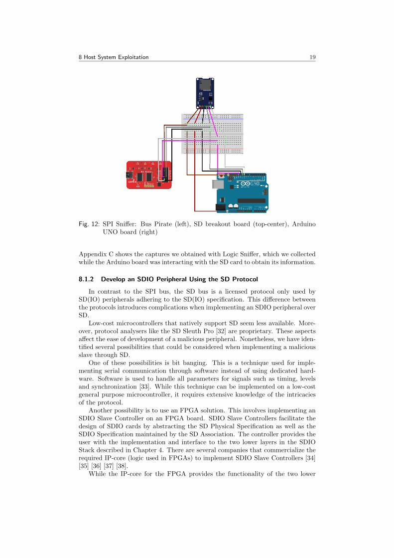
In addition, low-cost sniffers for SPI can be constructed. These can be used tocapture data being transferred between the master and the slave. We implementedsuch a sniffer by using a low-cost general purpose bus sniffer (Bus Pirate [29]). Wesniffed SPI communication between an Arduino Board (master) and an SD storagecard (slave). The code loaded on the Arduino board made use of the SPI and SDlibraries to read information from the SD card such as its type and its partitions[30]. Figure 12 shows a schematic diagram of the SPI sniffer setup we used.
By analysing the captured communication, it is possible to reverse engineerthe protocol. Gathering information such as commands being sent by the masterand responses being sent by the slave may become helpful in the development ofa malicious peripheral. Especially, when the complete specification (which givesdetails about specific commands and timing) is not available.
The analysis of the data can be facilitated by logic analysers. There are severalopen source analysers available for SPI. For our research we used Logic Sniffer [31].
8 Host System Exploitation 19
Fig. 12: SPI Sniffer: Bus Pirate (left), SD breakout board (top-center), ArduinoUNO board (right)
Appendix C shows the captures we obtained with Logic Sniffer, which we collectedwhile the Arduino board was interacting with the SD card to obtain its information.
8.1.2 Develop an SDIO Peripheral Using the SD Protocol
In contrast to the SPI bus, the SD bus is a licensed protocol only used bySD(IO) peripherals adhering to the SD(IO) specification. This difference betweenthe protocols introduces complications when implementing an SDIO peripheral overSD.
Low-cost microcontrollers that natively support SD seem less available. More-over, protocol analysers like the SD Sleuth Pro [32] are proprietary. These aspectsaffect the ease of development of a malicious peripheral. Nonetheless, we have iden-tified several possibilities that could be considered when implementing a maliciousslave through SD.
One of these possibilities is bit banging. This is a technique used for imple-menting serial communication through software instead of using dedicated hard-ware. Software is used to handle all parameters for signals such as timing, levelsand synchronization [33]. While this technique can be implemented on a low-costgeneral purpose microcontroller, it requires extensive knowledge of the intricaciesof the protocol.
Another possibility is to use an FPGA solution. This involves implementing anSDIO Slave Controller on an FPGA board. SDIO Slave Controllers facilitate thedesign of SDIO cards by abstracting the SD Physical Specification as well as theSDIO Specification maintained by the SD Association. The controller provides theuser with the implementation and interface to the two lower layers in the SDIOStack described in Chapter 4. There are several companies that commercialize therequired IP-core (logic used in FPGAs) to implement SDIO Slave Controllers [34][35] [36] [37] [38].
While the IP-core for the FPGA provides the functionality of the two lower

8 Host System Exploitation 20
layers, the business logic corresponding to the third layer still needs to be im-plemented by the developer. This process might have a steep learning curve as itrequires developing for an unconventional platform. This approach does not requiremodifications on the host, as the SDIO peripheral may be engineered to interactwith already existing drivers on the host system.
8.2 Modify Existing Firmware
Besides developing a new SDIO peripheral that exploits an existing driver, thefirmware of existing peripherals may be modified to fulfil the same purpose. InBadUSB - On Accessories that Turn Evil Karsten Nohl and Jakob Lell demon-strated how the lack of encryption and cryptographic signatures allow for the mod-ification of USB peripherals’ firmware.
To modify SDIO peripherals’ firmware, reverse engineering firmware binaries isindispensable as its source code is not available. Depending on the target architec-ture of the binary, a suitable debugger or disassembler might be used to ease thefirmware analysis. This may reveal interesting functions that might subsequentlybe hooked to change the behaviour of the SDIO peripheral.
For instance, a function that flushes WLAN packets to the host might be hookedto inspect each packet and make changes accordingly. The function can be alteredto filter DHCP-reply packets and change the DNS server resulting in the attackscenario as described in Section 3.1.
Two approaches in loading firmware to the SDIO peripheral were encounteredduring our research:
• Firmware loaded from flash memory
• Firmware loaded from the host
In the first approach an SDIO peripheral incorporates a chip, such as flash memory,to store its firmware. When the device boots it will fetch the firmware from theflash memory and start executing instructions accordingly. This approach enablesan adversary to modify a peripheral’s firmware without having access to the host.
In contrast, the second approach relies on the host to serve the peripheral’sfirmware. When the peripheral boots it will fetch the firmware from the host(provided from /lib/firmware/ on Linux systems) and start executing instructionsas per the firmware received. This approach suggests that a host machine mustfirst be compromised in order to serve malicious firmware to the SDIO peripheral.This seemingly provides a protection against SDIO peripheral attacks as privilegedaccess on the host is required.
However, a malicious peripheral can still be developed to exploit the correspond-ing driver and perform the attack. This peripheral may incorporate its own flashmemory, loaded with malicious firmware, that responds as if uploading firmwarefrom the host was successful. As the driver finishes uploading the firmware with-out any issues, it will consider the peripheral to be in a valid state and proceedoperation regardless of the actual firmware being executed on the peripheral.
During our research we investigated the two SDIO peripherals mentioned inSection 1.5. At least one of these peripherals, the ESP8266, was susceptible tofirmware modification. We desoldered the chip’s flash memory to expose its SDIOpins, which allowed us to both flash firmware and interact with the microcontrollerdirectly over SDIO from our host system.
8 Host System Exploitation 21
An SDK for the ESP8266 is provided by its manufacturer to develop new appli-cations for its microcontroller [39]. However, SDIO firmware example code is notcontained within the SDK and may only be obtained after signing an NDA. Thefirmware has a proprietary format which needs to be reverse engineered to developnew SDIO applications.
Despite the unavailability of this code, we successfully uploaded new SDIOfirmware to the ESP8266 microcontroller, that originates from the Linux Rockchiprepository [40]. The repository contains two binary firmware files which are up-loaded to the peripheral by the driver and are executed accordingly. This allowedus to program the microcontroller and use the chip’s SDIO WLAN functionality.However, as the firmware’s format is proprietary we were unable to implementmalicious modifications.
In an effort to modify the ATWILC1000-SD’s firmware, we compiled its latestdrivers and included them in the Linux kernel. However, we were unable to verifythe succesful modification, as the corresponding wilc1000 drivers are in stagingphase and did not work properly during experimentation. Efforts to patch thesedrivers manually were not effective and resulted in erroneous behaviour.
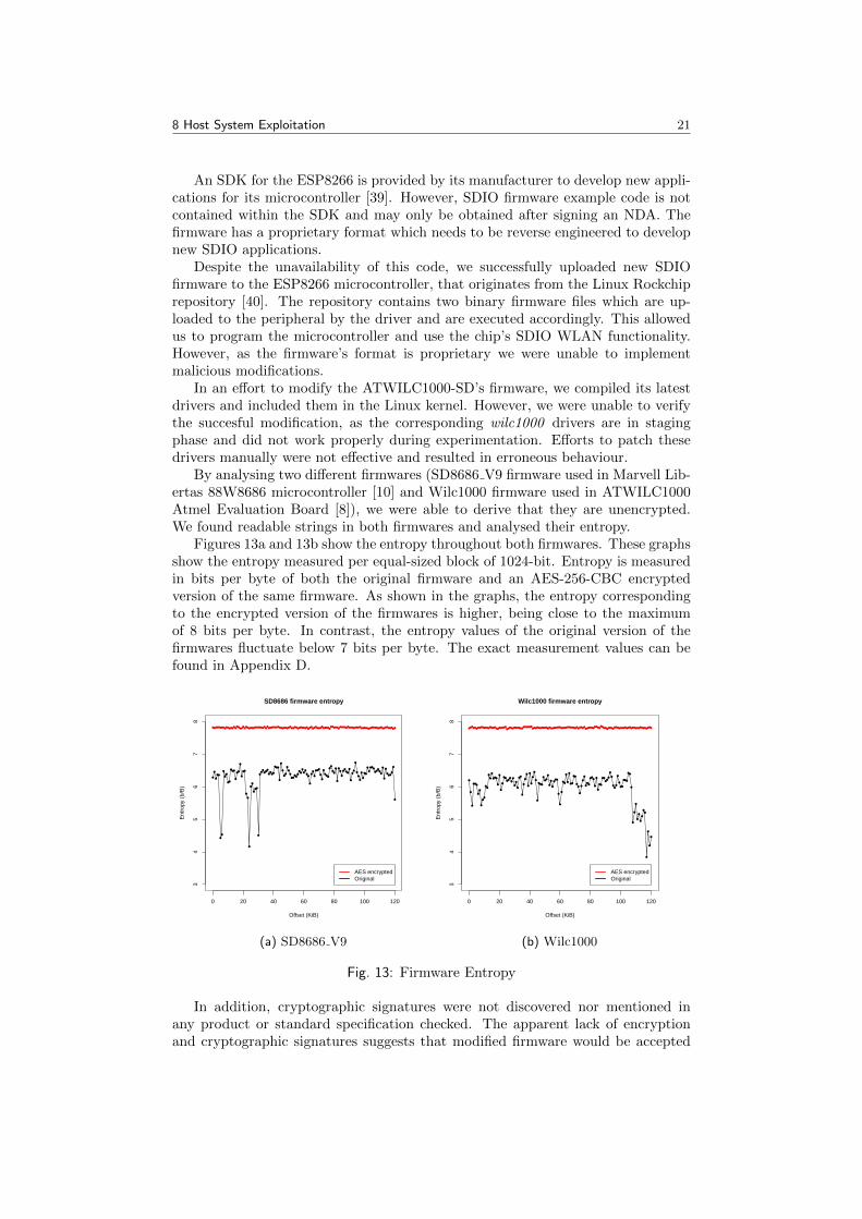
By analysing two different firmwares (SD8686 V9 firmware used in Marvell Lib-ertas 88W8686 microcontroller [10] and Wilc1000 firmware used in ATWILC1000Atmel Evaluation Board [8]), we were able to derive that they are unencrypted.We found readable strings in both firmwares and analysed their entropy.
Figures 13a and 13b show the entropy throughout both firmwares. These graphsshow the entropy measured per equal-sized block of 1024-bit. Entropy is measuredin bits per byte of both the original firmware and an AES-256-CBC encryptedversion of the same firmware. As shown in the graphs, the entropy correspondingto the encrypted version of the firmwares is higher, being close to the maximumof 8 bits per byte. In contrast, the entropy values of the original version of thefirmwares fluctuate below 7 bits per byte. The exact measurement values can befound in Appendix D.
0 20 40 60 80 100 120
34
56
78
SD8686 firmware entropy
Offset (KiB)
Ent
ropy
(b/
B)
● ● ● ● ● ● ● ●●
● ●● ● ●
●●
●●
● ●●
●●
● ● ● ● ●● ● ● ● ● ●
●●
●● ● ● ● ● ● ● ● ● ● ● ● ● ●
●● ●
● ●● ● ● ● ● ●
●●
● ●●
● ●● ● ●
●● ● ● ●
●
● ●● ● ●
●● ● ● ● ●
● ● ● ● ● ● ● ● ●● ● ● ● ● ●
● ● ● ● ●● ● ●
● ● ● ●● ● ●
●●
●
●
●
● ●
●
●
●
●
●
●●
●● ●
●
●●
●
●
● ●
●
●
●
●
●
●
●●
●
●
●
●
●●
●
●
●
●●
●● ●
●
●
●
●
●
●
●
●
● ●
●●
●
●●
●
●
●
●
●
●
●
●
●
● ●●
●
●
●
●●
●
●
●
●
●
●
●
●
●
●
●●
●●
●
●
●
●
●
●
●
●
●
●
●●
●
●
● ●●
●●
●
●
●
●
●
●
●● ●
●
●
●
AES encryptedOriginal
(a) SD8686 V9
0 20 40 60 80 100 120
34
56
78
Wilc1000 firmware entropy
Offset (KiB)
Ent
ropy
(b/
B)
●●
●● ●
●● ● ● ● ● ● ● ●
●● ● ●
● ●● ● ● ● ●
●●
● ● ● ● ● ● ● ● ●● ● ● ● ● ●
●● ●
● ● ● ● ● ● ●●
●● ● ● ● ● ● ●
● ● ● ● ● ● ● ● ● ●●
●● ● ●
●
● ● ● ● ● ●● ●
● ●
● ●● ●
●● ● ● ●
● ● ● ● ● ● ● ● ● ● ●● ● ● ● ● ●
● ● ● ●●
● ●●
●
●
●
● ●●
●
●
●
●
●
●●
●
●
●
●●
●
●
●
●
●
●●
●●
●
●
●
●
●
●
●●
●
●
●
●
●
●
●
●
●
●
●
●● ●
●
●●
●
●
●
●
●
● ●
●
●
●
●●
●
●
●
● ●
● ●
●
●
●
●
●
●
●
●●
●●
●
●
●
●
● ●
● ●
●●
●
●
●
●
●
●
●
●
● ●
● ●●
●●
●
●
●
●
●
●
●
●
●
●
●
●
●
●
AES encryptedOriginal
(b) Wilc1000
Fig. 13: Firmware Entropy
In addition, cryptographic signatures were not discovered nor mentioned inany product or standard specification checked. The apparent lack of encryptionand cryptographic signatures suggests that modified firmware would be accepted

8 Host System Exploitation 22
by SDIO peripherals, as their microcontrollers would not be able to verify thefirmware’s authenticity based on cryptography.
9 Evaluating SDIO Attacks 23
9 Evaluating SDIO Attacks
This chapter evaluates on different aspects regarding SDIO-based attacks. Sec-tion 9.1 discusses the difference between the two methods proposed in Chapter 8 todevelop a malicious SDIO peripheral. Section 9.2 examines the effectiveness of theattacks based on the two different communication protocols: SPI and SD. Finally,Section 9.3 discusses SDIO-based attacks in comparison to USB-based attacks.
9.1 Creating New Firmware vs. Modifying Existing Firmware
The first method mentioned in Chapter 8 encompasses creating an SDIO pe-ripheral from scratch. This implies that the adversary would need to implementthe three layers of the SDIO Stack from the peripheral. This is different from thesecond method, which requires modifying the firmware of an existing SDIO periph-eral. As the three layers of the SDIO Stack have been already implemented by themanufacturer in an existing peripheral, an adversary is only required to alter itsbusiness logic. Therefore, a malicious peripheral based the second method wouldpotentially require less resources.
However, creating a malicious SDIO peripheral from scratch is more flexible, asthe implementation is not bounded by specific firmware of a particular manufac-turer.
9.2 Using the SD Protocol vs. Using the SPI Protocol
SPI presents several advantages when considering implementation details of amalicious SDIO peripheral. As the protocol is commonly used by many applicationsand microcontrollers, more low-cost and open source products for this protocol areavailable. This implies that the implementation of a malicious SDIO peripheralusing the SPI protocol would be more convenient than implementing it using theSD protocol.
However, SPI presents a major disadvantage as it is not the default protocolused to communicate with SDIO peripherals. The host (master) decides whatcommunication protocol to use, and might not necessarily support SPI. Therefore,using the SPI protocol as an attack vector might be less effective. As SD is thedefault protocol, a malicious peripheral using SD will presumably affect a widerrange of (modern) hosts as compared to SPI.
9.3 SDIO vs. USB Attacks
SDIO presents similarities with USB, in the sense that both are used to addcapabilities to a host. Both USB and SDIO utilise a universal bus, which can beused to connect different types of peripherals. In both cases, peripherals includean identifiable string for the host to load the appropriate drivers. Despite theirsimilarities, SDIO and USB also present several differences.
The attack surface is composed of the available hosts and peripherals susceptibleto SDIO or USB-based attacks. Even though there are a number of different typesof SDIO aware hosts (e.g. laptops, tablets, PDAs), there are presumably moredevices that support USB (e.g. desktops, laptops, printers, routers, etc). Whenconsidering SDIO peripherals, there are few vendors and products available asopposed to USB peripherals. Altogether, USB seemingly presents a bigger attack

9 Evaluating SDIO Attacks 24
surface as compared to SDIO. This increases the probability of USB-based attacksover SDIO-based attacks.
Another aspect when considering the probability of successful exploitation, isthe inconspicuousness of the attack. For attacks to be more effective it is preferablethat the peripheral goes unnoticed when plugged into the host system. We ratio-nalise that SDIO peripherals have an advantage as they generally do not protrudefrom the port as opposed to USB peripherals.
In addition, it is preferable that the user does not notice malicious behaviourwhen the peripheral is plugged in. If an aware user expects to connect a storagedevice, it may be suspicious when the host does not recognize the peripheral as such.In BadUSB, malicious capabilities may be hidden by emulating a USB hub. Thisway, the host perceives the peripheral as multiple USB devices, one of them beingstorage, the other being malicious. In SDIO-based attacks this can be achieved bypresenting the device as a combo card, which incorporates both memory storageand I/O functionality.
The ease of exploitation is another considerable aspect. In the case of SDIO,there are no off-the-shelf products available yet, that provide a platform to emu-late SDIO peripherals. This makes host exploitation more difficult as adversariesneed to implement one of the methods described in Chapter 8. In contrast, forUSB there are devices available such as USB Armory [41], that provide platformsfor developing and running several applications, as well as USB device emulationcapabilities.
Furthermore, SDIO peripherals generally provide WLAN or Bluetooth capabil-ities, whereas USB provides a wider range of capabilities. This makes USB moreflexible and vulnerable for a wider range of possible attacks. For instance, USBprovides MTP (media device) and HID capabilities such as keyboards and mice,that are not directly encompassed by SDIO. However, some capabilities, such askeyboards and mice, can be emulated via Bluetooth and may thus be used withSDIO.
How peripherals are displayed in the user’s interface depends on their capabili-ties. In some cases peripherals connected through SDIO might be more obtrusiveas compared to USB. For instance, connected USB HID devices will generally onlyappear in certain (graphical) dialogues, whereas connected Bluetooth devices areshown as an icon on the desktop.

10 Discussion 25
10 Discussion
In this research we investigated whether SDIO could be considered as a newattack vector against SDIO aware hosts. Our results suggest that it is possible toexploit a host system by means of SDIO, as no protections were found to preventthis. Vendors could sign their firmware to prevent the execution of modified code ontheir SDIO peripherals. Nonetheless, it seems such security measures are generallynot implemented. Entropy tests conducted on two distinct SDIO firmware binariesand readable strings suggest that no (strong) encryption is being used. Further-more, no evidence was found of usage of cryptographic signatures. However, it isnot possible to generalise this result to peripherals outside of our testbed.
SDIO attacks are feasible, provided a malicious SDIO peripheral is either newlycreated or modified. The development of a malicious SDIO peripheral is time con-suming and expensive. Licensing is required to access the complete specificationsfor SD and SDIO. Moreover, there are no low cost off-the-shelf emulation devicesyet to accelerate development of SDIO applications. However, once a maliciousSDIO firmware has been developed, it may be copied and distributed to many pe-ripherals. Adversaries with less resources may benefit from this as devices may beobtained for a fraction of the costs as occurred with USB Rubber Ducky [42].
Each firmware is handled by specific manufacturer drivers, instead of beinghandled by a generic driver. It is therefore not possible to create a malicious generalpurpose SDIO peripheral; all steps in developing a malicious SDIO peripheral needto be redone when targeting a different SDIO driver.
The risk of this attack vector is composed by the probability of such an attackto occur, and the impact it has on the host. There are two main factors to beconsidered when examining the probability of the attack.
The first factor is the attack surface, which consists of SDIO aware hosts only.This diminishes the population of target hosts as non-SDIO SD slots are not affectedby this attack vector. Nonetheless, many hosts such as laptops, tablets and PDAsare SDIO aware and might subsequently be compromised. Moreover, there areseveral devices, such as tablets and PDAs, in which SD(IO) peripherals are theonly supported external media. This makes it more difficult to apply preventiontechniques and policies such as blocking SD(IO) slots.
The second factor is the fact that the host needs to have access to the driversto handle the peripheral for the attack to be successful. In cases in which thedrivers are installed on the host, this should not be considered as a limitation forproduction-ready modules; once the Linux kernel detects a new device, it runsmodprobe which loads the kernel module required to handle the device. However,staging drivers (e.g. wilc1000) are not loaded automatically with modprobe. Incases in which the peripheral contains drivers in the CSA memory area, the hostcan directly interact with the peripheral by means of those drivers. This increasesthe probability of an attack being successful.
Successful exploitation may have a considerable impact on the victim’s host.Its main reason, is that SDIO provides a wide range of functionalities that canbe misused. Depending on the exploited functionality, the inflicted damage mayvary. Moreover, SDIO might be exploited to perform attacks beyond its originalcapabilities. For instance, if a Bluetooth keyboard were to be emulated by themalicious SDIO peripheral and paired with the host, arbitrary keystrokes could beexecuted on the host system. This attack could be used in staging the deploymentof malware and breaching the air gap in highly secured environments.
11 Conclusion 26
11 Conclusion
SDIO (Secure Digital Input Output) is an extension to the SD specification tocover I/O functions. SDIO peripherals are used to extend the capabilities of SDIOaware hosts, including WLAN and Bluetooth among others. A host is consideredto be SDIO aware when it incorporates a compliant microcontroller and compatibleSDIO drivers.
Despite SDIO’s initial specification being released in 2001, little research re-garding this topic has been published. Literature on SDIO is mainly restrictedto its specification, which requires licensing to access the complete version. Thiscompelled us to develop models and concepts that would otherwise be consideredpart of a preliminary study of the state of art.
SDIO may operate in both SD and SPI mode. Both modes must be implementedin SDIO compliant peripherals. SDIO aware hosts do not share this requirement,and may support either one of these modes or both.
Analogous to USB, SDIO uses a universal bus. Any SDIO capability and ac-companying driver could potentially be exploited for malicious intent. For instance,SDIO WLAN drivers might be exploited to alter a host’s network configuration witha malicious DNS server. Moreover, some SDIO drivers, such as SDIO Bluetoothones, might be exploited in staging attacks against higher-level non-SDIO drivers(e.g. Bluetooth keyboard drivers). This extends the attack surface beyond theoriginal SDIO drivers.
A malicious SDIO peripheral could be developed by either modifying existingfirmware or by implementing new firmware. The former relies on reverse engineeringexisting firmware to hook functions and modify their behaviour. The latter relies onimplementing new firmware that advertises itself as an existing peripheral. ModernSD(IO) card readers tend not to implement SPI in favour of SD. A maliciousperipheral implementing SD is therefore expected to be more effective.
We currently deem an actual SDIO attack less probable than a USB attack,due to the unavailability of development platforms for SDIO. However, consideringthe similarities with USB and the impact of BadUSB in computer security, werecognize SDIO as a new attack vector.

12 Mitigations 27
12 Mitigations
In this chapter we highlight mitigations to counteract SDIO-based attacks. At-tacks can be mitigated either on the host side or on the peripheral side, and prefer-ably on both.
On the peripheral side, vendors should strive to protect their firmware frommodification. If firmware is not protected, a malicious SDIO peripheral could bedeveloped more conveniently. One way manufacturers could protect their firmwareis to sign it. This way, SDIO peripherals will be able to verify whether they areexecuting the original firmware, thus being able to detect a (malicious) modifiedversion. However, this process is not trivial as it involves secure key storage andprocessing. In addition, vendors could encrypt their firmware to make the reverseengineering process more complicated.
On the host side, several countermeasures such as disabling unused SD(IO)ports and removing unused SDIO drivers could be implemented to mitigate theseattacks. However, these policies may not benefit usability. Furthermore, awarenessof this new attack vector should be raised to end-users. As such, individuals willbe able to protect themselves against this type of attack.
It may be assumed that adversaries with enough resources will eventually cir-cumvent these security measures. However, the mitigations proposed will up theante, making exploitation more complicated and less likely.

13 Ethical Considerations 28
13 Ethical Considerations
During our research we found that SDIO can be used as an attack vector onSDIO aware hosts. We did not implement a malicious peripheral, however we deemthis to be feasible for adversaries having enough resources.
By conducting and publishing this research, we aim to raise awareness on themalicious capabilities of SDIO peripherals and insecurity of SDIO aware hosts.
We hope this research enables individuals to protect themselves against thesetypes of attacks and triggers the security community to develop countermeasures.

14 Future Work 29
14 Future Work
The focus of this project was to research if SDIO could be considered as anattack vector in a similar fashion as USB. Future research on this topic could focuson the implementation of a proof of concept to verify our results. The PoC couldconsist of a practical implementation of the attack scenarios described in Chapter3. In addition, we consider the exploration of potential attacks based on otherSDIO functionalities valuable research.
An important prerequisite for modifying existing SDIO peripherals’ firmwareencompasses the absence of encryption and cryptographic signatures. During ourresearch we successfully modified the firmware of one peripheral. Moreover, wefound no indication of encryption or cryptographic signatures in two other periph-erals’ firmware. Further research may explore whether these security measures areenforced by other vendors and if so, investigate how encryption and cryptographicsignature checks are implemented in SDIO peripherals and their firmware. Modifiedfirmware may be uploaded to the peripherals to verify these results.
In our research, we did not focus on vulnerabilities in hosts’ software suchas drivers. As these often run in kernel space, any vulnerability could have aconsiderable impact on the host. Further research may consist of finding suchvulnerabilities. As part of this research, an SDIO fuzzer could be designed anddeveloped to automate the process.
The exploitability of a host is partially determined by the available drivers. Inthis research, we examined the Linux kernel to determine what SDIO drivers existand how they are loaded. We found that modprobe probes the peripheral and loadsits corresponding modules accordingly. However, in other operating systems thismight work differently. While Microsoft documents USB initialisation and how adevice’s drivers are downloaded by Windows Update [43], it does not provide thesame level of detail in its SDIO documentation. Further research may be conductedto determine how non-Linux operating systems load SDIO drivers.
Likewise, user awareness is another considerable aspect in exploitation. Anattack could be successfully performed if peripherals loaded with malicious firmwareare unwittingly inserted by users. As opposed to USB [44], user awareness studieson SDIO peripherals have not yet been published.

15 References 30
15 References
[1] Parallella. Create SD Card. url: https://www.parallella.org/create-sdcard/ (visited on 07/06/2016).
[2] Technical Committee. SDIO Simplified Specification. Version 3.00. SD CardAssociation. 2400 Camino Ramon, Suite 375, San Ramon, CA 94583 USA,Feb. 2011.
[3] Karsten Nohl, Jakob Lell. BadUSB - On Accessories that Turn Evil. Sept. 11,2014. url: https://www.youtube.com/watch?v=nuruzFqMgIw (visited on06/02/2016).
[4] Andrew Huang, Sean Cross. 30C3: Exploration and Exploitation of an SDMemory Card. Dec. 29, 2013. url: https://www.youtube.com/watch?v=r3GDPwIuRKI (visited on 07/05/2016).
[5] Andrew Huang, Sean Cross. On Hacking MicroSD Cards. url: https://www.bunniestudios.com/blog/?p=3554 (visited on 07/05/2016).
[6] Andreas Loeffler, Andreas Deisinger. “A Microcontroller-based HF-RFIDReader Implementation for the SD-Slot”. In: (Apr. 2011).
[7] Technical Committee. SD Specifications Part E7 Wireless LAN SimplifiedAddendum. Version 1.10. SD Card Association. 2400 Camino Ramon, Suite375, San Ramon, CA 94583 USA, Mar. 2014.
[8] Atmel. ATWILC1000. url: http://www.atmel.com/devices/ATWILC1000.aspx (visited on 11/07/2016).
[9] Espressif. ESP8266EX Overview. url: https : / / espressif . com / en /
products/hardware/esp8266ex/overview (visited on 13/07/2016).
[10] Marvell. Wireless chipsets. url: https://wikidevi.com/wiki/Marvell
(visited on 11/07/2016).
[11] Technical Committee. Physical Layer Simplified Specification. Version 4.10.SD Card Association. 2400 Camino Ramon, Suite 375, San Ramon, CA 94583USA, Jan. 2013.
[12] SD Association. SDIO. url: https : / / www . sdcard . org / developers /
overview/sdio/index.html (visited on 07/06/2016).
[13] Opticon. H 21 - OptiWiki. Dec. 11, 2012. url: http://wiki.opticon.com/index.php/H_21 (visited on 21/07/2016).
[14] Opticon. H 16 - OptiWiki. Dec. 11, 2012. url: http://wiki.opticon.com/index.php/H_16 (visited on 21/07/2016).
[15] Transcend. User Manual Wi-Fi SD. Version 2.0. Transcend. 2400 CaminoRamon, Suite 375, San Ramon, CA 94583 USA, June 2014.
[16] Opticon. Hacking Transcend Wifi SD Cards. Aug. 12, 2013. url: http://hackaday.com/2013/08/12/hacking-transcend-wifi-sd-cards/ (visitedon 21/07/2016).
[17] Wikipedia. SDIO. url: https : / / en . wikipedia . org / wiki / Secure _
Digital#SDIO (visited on 11/07/2016).
[18] Texas Instruments. LM74 SPI/Microwire12-Bit Plus Sign Temperature Sen-sor. url: http://www.ti.com/lit/ds/symlink/lm74.pdf (visited on11/07/2016).

15 References 31
[19] Adafruit. i2c / SPI character LCD backpack. url: https://www.adafruit.com/product/292 (visited on 11/07/2016).
[20] Cactus Technologies. An Introduction To SD Card Interface. url: http:
/ / www . cactus - tech . com / files / cactus - tech . com / documents /
whitepapers/An%20Introduction%20To%20SD%20Card%20Interface.pdf
(visited on 07/07/2016).
[21] Technical Committee. SD Host Controller Simplified Specification. Version3.00. SD Association. 2400 Camino Ramon, Suite 375, San Ramon, CA 94583USA, Feb. 2011.
[22] Linus Torvalds. Linux kernel source tree. url: https : / / github . com /
torvalds/linux (visited on 07/05/2016).
[23] Ubuntu. Realtek Semiconductor Co., Ltd. RTS5227 PCI Express Card ReaderCardreader. url: http : / / www . ubuntu . com / certification / catalog /
component/pci/10ec:5227/ (visited on 07/07/2016).
[24] Elliot Williams. Raspberry Pi 2 WiFi Through Epic SDIO Hack. url: https:/ / hackaday . com / 2015 / 12 / 09 / raspberry - pi - wifi - through - sdio/
(visited on 07/05/2016).
[25] Mark Brown et. al. Overview of Linux kernel SPI support. url: https :
//www.kernel.org/doc/Documentation/spi/spi- summary (visited on21/07/2016).
[26] Gordon. Understanding SPI on the Raspberry Pi. url: https://projects.drogon.net/understanding- spi- on- the- raspberry- pi/ (visited on21/07/2016).
[27] Atmel. Atmel AVR 8-bit and 32-bit Microcontrollers. url: http://www.
atmel.com/products/microcontrollers/avr/ (visited on 08/07/2016).
[28] Arduino. SPI library. url: https://www.arduino.cc/en/Reference/SPI(visited on 07/06/2016).
[29] DANGEROUSPROTOTYPES. Bus Pirate. url: http : / /
dangerousprototypes.com/docs/Bus_Pirate (visited on 07/06/2016).
[30] Arduino. Using the SD library to retrieve information over a serial port. url:https://www.arduino.cc/en/Tutorial/CardInfo (visited on 21/07/2016).
[31] J.W Janssen. Logic Sniffer. url: https://www.lxtreme.nl/ols/ (visitedon 07/06/2016).
[32] Jinvani Systech Online. SD Sleuth Pro. url: http://jinvanisystech.com/sd_sleuth_pro.html (visited on 07/06/2016).
[33] Wikipedia. Bit banging. url: https://en.wikipedia.org/wiki/Bit_
banging (visited on 07/06/2016).
[34] XILINIX - all programmable. SDIO Slave Controller. url: http://www.
xilinx.com/products/intellectual-property/1-1tmch5.html (visitedon 07/06/2016).
[35] Microsemi. IP Module - SDIO Slave Controller. url: http : / / soc .
microsemi.com/products/ip/search/detail.aspx?id=715 (visited on07/06/2016).

15 References 32
[36] LATTICE - semiconductor. EP560: SD / SDIO / MMC Slave Con-troller. url: http : / / www . latticesemi . com / en / Products /
DesignSoftwareAndIP / IntellectualProperty / IPCore / EurekaCores /
EP560SDSDIOMMCSlaveController (visited on 07/06/2016).
[37] Hitech Global. SD/SDIO Device IP Core. url: http://www.hitechglobal.com/IPCores/SDSDIODevice.htm (visited on 07/06/2016).
[38] iWave - Embedding Intelligence. SDIO Slave Controller. url: http://www.iwavesystems.com/sdio-slave-controller.html (visited on 07/06/2016).
[39] Espressif. ESP8266 Document Map. Feb. 26, 2015. url: http : / / bbs .
espressif.com/viewtopic.php?f=67&t=225 (visited on 21/07/2016).
[40] al177. Linux kernel module driver for the ESP8089 WiFi chip. May 26, 2016.url: https://github.com/al177/esp8089 (visited on 21/07/2016).
[41] Inverse Path. OPEN SOURCE FLASH-DRIVE SIZED COMPUTER. url:https://inversepath.com/usbarmory (visited on 07/06/2016).
[42] Timo Dorr et. al. USB Rubber Ducky Wiki. url: http://usbrubberducky.com/#!index.md (visited on 22/07/2016).
[43] Microsoft. Universal Serial Bus (USB). url: https://msdn.microsoft.com/en-us/library/windows/hardware/ff538930(v=vs.85).aspx (vis-ited on 21/07/2016).
[44] Yael Grauer. Should You Plug That USB Drive Into Your Computer? (BewareOf Malware). Oct. 30, 2015. url: http://www.forbes.com/sites/ygrauer/2015 / 10 / 30 / usb - drive - malware - security - homeland - security -
cybersecurity/ (visited on 20/07/2016).
[45] ajlitt. RPi WiFi - Fast RPi WiFi without USB. url: https://hackaday.io/project/8678/instructions (visited on 11/07/2016).

A Acronyms 33
A Acronyms
AES Advanced Encryption Standard
AP Access Point
CIA Common Information Area
DHCP Dynamic Host Configuration Protocol
DNS Domain Name System
FPGA Field Programmable Gate Array
GPIO General Purpose Input/Output
GPS Global Positioning System
HID Human Interface Device
IoT Internet of Things
IP Internet Protocol
MitM Man-in-the-Middle
MTP Media Transfer Protocol
NDA Non-Disclosure Agreement
OS Operating System
PDA Personal Digital Assistant
RFID Radio Frequency Identification
SD Secure Digital
SDIO Secure Digital Input Output
SPI Serial Peripheral Interface
USB Universal Serial Bus
WLAN Wireless Local Area Network

B Raspberry Pi SDIO Pinout 34
B Raspberry Pi SDIO Pinout
Table 2 shows the GPIO pins of a Raspberry Pi 2 used to communicate withthe board through SDIO.
Tab. 2: Raspberry Pi 2 SDIO Pins [45]
SDIO Signal Raspberry PiCLK 15/GPIO22CMD 16/GPIO23D0 18/GPIO24D1 22/GPIO25D2 37/GPIO26D3 13/GPIO27
C Logic Sniffer Captures
Figure 14 shows the digital signals for the different lines used in the SPI protocol.A brief description of each of the lines and their correspondence with the namesshown in Table 1 can be found below:
• SS (CS): Slave Select line is used by the master to enable the slave it wantsto talk to.
• MISO (SDO): Master In Slave Out line is used by the slave to transfer datato the master.
• CLK (SCLK): Clock Signal line is used to determine the frequency of thecommunication.
• MOSI (SDI): Master Out Slave In line is used by the master to transferdata to the slave.
Fig. 14: SPI Lines
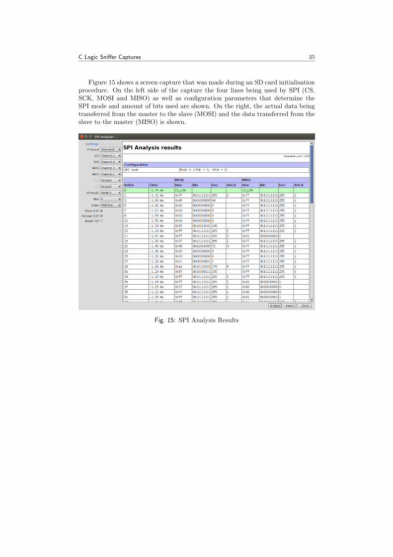
C Logic Sniffer Captures 35
Figure 15 shows a screen capture that was made during an SD card initialisationprocedure. On the left side of the capture the four lines being used by SPI (CS,SCK, MOSI and MISO) as well as configuration parameters that determine theSPI mode and amount of bits used are shown. On the right, the actual data beingtransferred from the master to the slave (MOSI) and the data transferred from theslave to the master (MISO) is shown.
Fig. 15: SPI Analysis Results

D Firmware Entropy 36
D Firmware Entropy
Tab. 3: Firmware Entropy
SD8686 V9 Wilc1000
Offset (hex) Original ent. (b/B) AES ent. (b/B) Offset (hex) Original ent. (b/B) AES ent. (b/B)0x0 6.282123 7.816399 0x0 6.196781 7.790906
0x400 6.454746 7.802034 0x400 5.835086 7.8156430x800 6.249155 7.821375 0x800 5.416778 7.8411110xC00 6.366582 7.818442 0xC00 6.089453 7.8005210x1000 6.357649 7.824689 0x1000 6.089927 7.8106950x1400 4.426039 7.811515 0x1400 6.057734 7.7811740x1800 4.531434 7.818418 0x1800 5.777246 7.8123920x1C00 6.475733 7.814030 0x1C00 5.894327 7.8103980x2000 6.310075 7.789059 0x2000 5.429183 7.8270620x2400 6.384919 7.820586 0x2400 5.599103 7.8214400x2800 6.130767 7.813376 0x2800 5.664827 7.8048160x2C00 6.159059 7.787654 0x2C00 6.017343 7.8156350x3000 6.526084 7.804782 0x3000 5.966877 7.8070680x3400 6.482011 7.793845 0x3400 6.366095 7.7970090x3800 6.491932 7.833620 0x3800 6.256537 7.8311460x3C00 6.236911 7.796921 0x3C00 6.408006 7.8096730x4000 6.432307 7.847315 0x4000 6.251089 7.8077540x4400 6.466668 7.825627 0x4400 6.282799 7.8239550x4800 6.696223 7.789991 0x4800 6.261074 7.7879230x4C00 6.318827 7.793375 0x4C00 6.065895 7.7733690x5000 6.471171 7.840938 0x5000 6.356354 7.8123600x5400 6.485790 7.794561 0x5400 5.901363 7.8022510x5800 5.783693 7.835262 0x5800 6.100675 7.8135150x5C00 5.660242 7.810968 0x5C00 6.292268 7.8146120x6000 4.162811 7.792157 0x6000 6.268948 7.8344950x6400 6.005361 7.807295 0x6400 6.179029 7.7616810x6800 6.098992 7.803388 0x6800 6.210149 7.7873960x6C00 5.847149 7.800566 0x6C00 6.269547 7.8149050x7000 5.933182 7.821835 0x7000 6.157793 7.8006390x7400 5.955469 7.820296 0x7400 6.262275 7.7925210x7800 4.507794 7.818671 0x7800 6.036280 7.8124070x7C00 6.378093 7.822686 0x7C00 6.145536 7.8131590x8000 6.447655 7.813889 0x8000 5.967199 7.8074000x8400 6.507003 7.805989 0x8400 6.277762 7.8089370x8800 6.431914 7.835076 0x8800 6.313068 7.7882790x8C00 6.471262 7.793253 0x8C00 5.755092 7.7915510x9000 6.516406 7.842450 0x9000 6.073859 7.8325680x9400 6.387915 7.799170 0x9400 6.234864 7.8350580x9800 6.445048 7.814121 0x9800 6.388277 7.8288320x9C00 6.384710 7.815529 0x9C00 6.026602 7.8347880xA000 6.417160 7.829903 0xA000 6.413248 7.8318720xA400 6.615589 7.820571 0xA400 6.097927 7.8453910xA800 6.588879 7.824128 0xA800 6.295916 7.784753

D Firmware Entropy 37
Tab. 3: Firmware Entropy
SD8686 V9 Wilc1000
0xAC00 6.590554 7.834618 0xAC00 6.450563 7.8092050xB000 6.204366 7.816639 0xB000 6.200918 7.7982140xB400 6.717976 7.808683 0xB400 5.579083 7.8216610xB800 6.498007 7.793328 0xB800 6.111125 7.8041480xBC00 6.336890 7.807164 0xBC00 6.078714 7.8025010xC000 6.391718 7.809967 0xC000 6.063906 7.8096150xC400 6.603862 7.795499 0xC400 6.295670 7.8100100xC800 6.495353 7.811748 0xC800 6.191030 7.8124540xCC00 6.386407 7.838251 0xCC00 6.226064 7.8135520xD000 6.271982 7.798142 0xD000 6.351674 7.7849920xD400 6.278694 7.797673 0xD400 6.048070 7.8170740xD800 6.346745 7.828686 0xD800 6.181060 7.7936520xDC00 6.308050 7.819614 0xDC00 6.003390 7.7915340xE000 6.381152 7.789465 0xE000 6.162673 7.8058860xE400 6.476464 7.805906 0xE400 6.220248 7.8118300xE800 6.425268 7.823496 0xE800 6.216663 7.8167910xEC00 6.533572 7.811808 0xEC00 5.781208 7.8197680xF000 6.431959 7.808271 0xF000 5.457941 7.8232570xF400 6.499904 7.798325 0xF400 5.838138 7.7990770xF800 6.381171 7.821593 0xF800 6.152044 7.8066810xFC00 6.327072 7.776229 0xFC00 6.110505 7.8081340x10000 6.095266 7.813516 0x10000 6.376960 7.8155170x10400 6.387887 7.831374 0x10400 6.140733 7.8249130x10800 6.470291 7.785457 0x10800 6.415055 7.8275540x10C00 6.326426 7.813777 0x10C00 6.088240 7.8142940x11000 6.497502 7.831452 0x11000 6.105161 7.8181310x11400 6.504326 7.799271 0x11400 6.328910 7.8117340x11800 6.536592 7.798512 0x11800 6.313498 7.7972300x11C00 6.369887 7.803129 0x11C00 6.079704 7.8228360x12000 6.227220 7.839872 0x12000 6.003947 7.7865290x12400 6.505688 7.801060 0x12400 5.799353 7.8177590x12800 6.383635 7.809317 0x12800 6.020696 7.8232670x12C00 6.341630 7.815041 0x12C00 6.194943 7.8025180x13000 6.305724 7.809067 0x13000 6.315341 7.8300450x13400 6.564890 7.778000 0x13400 6.033194 7.7777600x13800 6.629823 7.841609 0x13800 6.110680 7.7925480x13C00 6.477083 7.839465 0x13C00 6.067308 7.8106810x14000 6.423005 7.811619 0x14000 6.261553 7.8157600x14400 6.560365 7.822127 0x14400 6.288602 7.8080870x14800 6.173809 7.819352 0x14800 6.232241 7.8009460x14C00 6.563699 7.786751 0x14C00 6.021768 7.8385750x15000 6.477254 7.833468 0x15000 6.271147 7.8414960x15400 6.337297 7.829270 0x15400 5.907614 7.8154690x15800 6.484721 7.824830 0x15800 6.072703 7.8033770x15C00 6.536767 7.827070 0x15C00 6.057596 7.8556550x16000 6.459793 7.806964 0x16000 6.268259 7.8348230x16400 6.425674 7.837323 0x16400 6.266129 7.800098

D Firmware Entropy 38
Tab. 3: Firmware Entropy
SD8686 V9 Wilc1000
0x16800 6.543259 7.816521 0x16800 6.166257 7.8064850x16C00 6.198983 7.817839 0x16C00 6.211079 7.7732950x17000 6.411231 7.814982 0x17000 6.278467 7.8023970x17400 6.489958 7.800252 0x17400 6.437000 7.8106970x17800 6.739250 7.818868 0x17800 6.305361 7.8002380x17C00 6.440302 7.817690 0x17C00 6.034212 7.7820880x18000 6.325242 7.815903 0x18000 5.969841 7.8186920x18400 6.207766 7.832533 0x18400 6.043584 7.8235770x18800 6.434275 7.798508 0x18800 6.333866 7.8141560x18C00 6.268040 7.798674 0x18C00 6.127458 7.7940500x19000 6.416762 7.806698 0x19000 5.996880 7.8039750x19400 6.395780 7.802857 0x19400 6.006530 7.8022400x19800 6.589188 7.793649 0x19800 6.208177 7.8034200x19C00 6.472562 7.780894 0x19C00 6.200652 7.8188660x1A000 6.590784 7.803909 0x1A000 6.179185 7.7981050x1A400 6.599236 7.818867 0x1A400 6.419692 7.8115150x1A800 6.557897 7.816901 0x1A800 6.390383 7.8217500x1AC00 6.450935 7.812819 0x1AC00 5.983445 7.7960190x1B000 6.484309 7.813880 0x1B000 4.902346 7.8133870x1B400 6.536098 7.792983 0x1B400 5.215895 7.8129630x1B800 6.471651 7.804992 0x1B800 5.472545 7.7965010x1BC00 6.405682 7.822902 0x1BC00 5.004568 7.8031380x1C000 6.587034 7.794353 0x1C000 5.161797 7.7988000x1C400 6.251813 7.797026 0x1C400 4.948997 7.8212210x1C800 6.550434 7.817870 0x1C800 5.094176 7.8107940x1CC00 6.403757 7.828598 0x1CC00 5.279307 7.7960350x1D000 6.351541 7.803989 0x1D000 5.206772 7.8073210x1D400 6.364537 7.799708 0x1D400 3.841399 7.7839860x1D800 6.435129 7.816044 0x1D800 4.625766 7.8105000x1DC00 6.605740 7.776826 0x1DC00 4.193379 7.8256310x1E000 5.605661 7.804576 0x1E000 4.462423 7.8018100x1E400 4.231247 7.440353 0x1E400 4.314079 7.705897