scc evlauation by oems
TRANSCRIPT

7/27/2019 SCC Evlauation by OEMS
http://slidepdf.com/reader/full/scc-evlauation-by-oems 1/84
* " ** *
Commission of the European Communities
COST
p h y s i c a l s c i e n c e s
Stress corrosion crackingand corrosion fatigue of steam-turbine
rotor and blade materials
Report
EUR 13186 EN

7/27/2019 SCC Evlauation by OEMS
http://slidepdf.com/reader/full/scc-evlauation-by-oems 2/84

7/27/2019 SCC Evlauation by OEMS
http://slidepdf.com/reader/full/scc-evlauation-by-oems 3/84

7/27/2019 SCC Evlauation by OEMS
http://slidepdf.com/reader/full/scc-evlauation-by-oems 4/84

7/27/2019 SCC Evlauation by OEMS
http://slidepdf.com/reader/full/scc-evlauation-by-oems 5/84
Commission of the European Communities
COST
Stress corrosion crackingand corrosion fatigue of steam-turbine
rotor and blade materials
M. O. Speidel,1
J . Denk,2
B. Scarlin2
11nstitute of Metallurgy
CH-Eth, Zürich
2Asea Brown Boveri
CH-Baden
Edited by
J . B. Marriott
Commission of the European Communities
1991
Contract No: ECI COST-0010-CH (CH)
Directorate-General P A R L E U R O ? . B i b Ü A
/ V \ M
Science, Research and Developrrjetø c < §¡fi¡s5$$$srf)
C f EUR 13186 EN
7/27/2019 SCC Evlauation by OEMS
http://slidepdf.com/reader/full/scc-evlauation-by-oems 6/84
Published by theCOMM ISSION OF THE EUROPEAN COMM UNITIES
Directorate-GeneralTelecommunications, Information Industries and Innovation
L-2920 Luxembourg
LEGAL NOTICE
Neither the Commission of the European Communities nor any person acting on behalf
of the Commission is responsible for the use which might be made of the following information
Cataloguing d ata can be found at the end of this publication
* Luxembourg: Pffjce for O fficial Publications of the European Communities, 1991ISBN 92-826-2017-4 ^ , 4 | Catalogue number: CD-NA-13186-EN-C
_ _ , <s> E C S C T E E C - E A E C , Brussels • Luxembourg, 1991
. « J Printed in Germany

7/27/2019 SCC Evlauation by OEMS
http://slidepdf.com/reader/full/scc-evlauation-by-oems 7/84
PREFACE
Stress Corrosion Cracking and Corrosion Fatigue of Steam Turbine
Rotor and Blade Materials
Research on high temperature materials which are critical for the
safe and efficient operation of power engineering equipment hasbeen an important feature of COST concerted action programmes forthe last eighteen years; starting with COST 50; "Materials forGas Turbines".
In recent years specific attention, has been devoted to"Materials for Steam Turbines" - COST 505. The countriesrepresented in this work have been Austria, Belgium, Denmark,Finland, Germany, Italy, Sweden, Switzerland, United Kingdom,together with the Joint Research Centre of the Commission of theEuropean Communities. Jointly, organisations from thesecountries have tackled a, range of problems concerned with theimprovement and reliability of steam turbines.
One of the coordination groups studied features involved in thefields of stress corrosion and corrosion fatigue attack which arevery important considerations for rotating components in the lowpressure cylinders of a steam turbine. They also characterised anewly developed steel and considered its suitability for use assteam turbine blades in this part of the machine.
The work of this group is examined in the light of present dayliterature and experience in, this critical review which wasconducted with financial assistance from the Commission of theEuropean Communities. The interests of the Management Committee
- of COST 501 and the wider European industrial situation wererepresented during the study by a "Steering Group" comprisingDr. S. Ragazzoni, ENEL, Milan, I and Dr. P. Greenfield, GECAlsthom, Leicester, UK.
J. B. MarriottSecretariat, COST 505
JBM/jb/5/0828Petten, 5th June 1990

7/27/2019 SCC Evlauation by OEMS
http://slidepdf.com/reader/full/scc-evlauation-by-oems 8/84

7/27/2019 SCC Evlauation by OEMS
http://slidepdf.com/reader/full/scc-evlauation-by-oems 9/84
CONTENTS
PREFACE III
1. Introduction 1
2. Chemical compositions of the steels investigated 1
3. Stress corrosion cracking and corrosion fatigue 2
4. Stress corrosion crack initiation 2
4.1 Corrosion pits, micro-cracks and macro-cracks 3 4.2 Constant extension rate testing, CERT 4
5. Stress corrosion crack propagation 5 5.1 Effects of steel composition on SCC growth
rates 7 5.2 Effect of mechanical properties on SCC growth
rates 7
6. .Stress corrosion crack branching 8
7. Corrosion fatigue crack initiation 9 7.1 Corrosion fatigue crack initiation in
LP rotor steels 9 7.2 Corrosion fatigue crack initiation in blading
materials 11
8. Fatigue and corrosion fatigue crack growth 11
9. A fracture mechanics analysis of crack initiation 12
10. Considerations concerning the mechanisms of SCC 13
11. Conclusions 17
12. Acknowledgement 19
13. References 19
TABLES 23
FIGURES 25
■ V -

7/27/2019 SCC Evlauation by OEMS
http://slidepdf.com/reader/full/scc-evlauation-by-oems 10/84

7/27/2019 SCC Evlauation by OEMS
http://slidepdf.com/reader/full/scc-evlauation-by-oems 11/84
1. Introduction
Modern steam turbines must retain a very high reliabilitythroughout their service life of typically 200,000 hours.Among the failure modes which have been observed in steam turbines during the last 20 years, stress corrosion cracking was
prominent, Ref./1 to 12/. Also, corrosion fatigue has been observed in steam turbine components such as blades and rotors,Ref./13,14/.
It is for these reasons that in the frame of COST program505, "Materials for Steam Turbines", research projects have beenundertaken to study stress corrosion and corrosion fatiguecracking of rotor and blading materials. These projects (seeTable 1) have been carried out and coordinated under Group 1 ofCOST 505. The present paper summarizes the results of this international cooperative research program and, therefore, is
essentially based on the final reports, Ref./15 through 27/.Together with additional information from the literature, anattempt is made to describe in quantitative terms the stresscorrosion and corrosion fatigue behaviours of steam turbinerotor and blade materials in service-related environments. It isexpected that this summary of the results of COST action 505will be useful for design, operation, development, life timecalculations and failure analysis of steam turbines. The papertreats
- stress corrosion crack initiation
- stress corrosion crack propagation- corrosion fatigue crack initiation- corrosion fatigue crack propagation
in turn for rotor materials and blade materials.
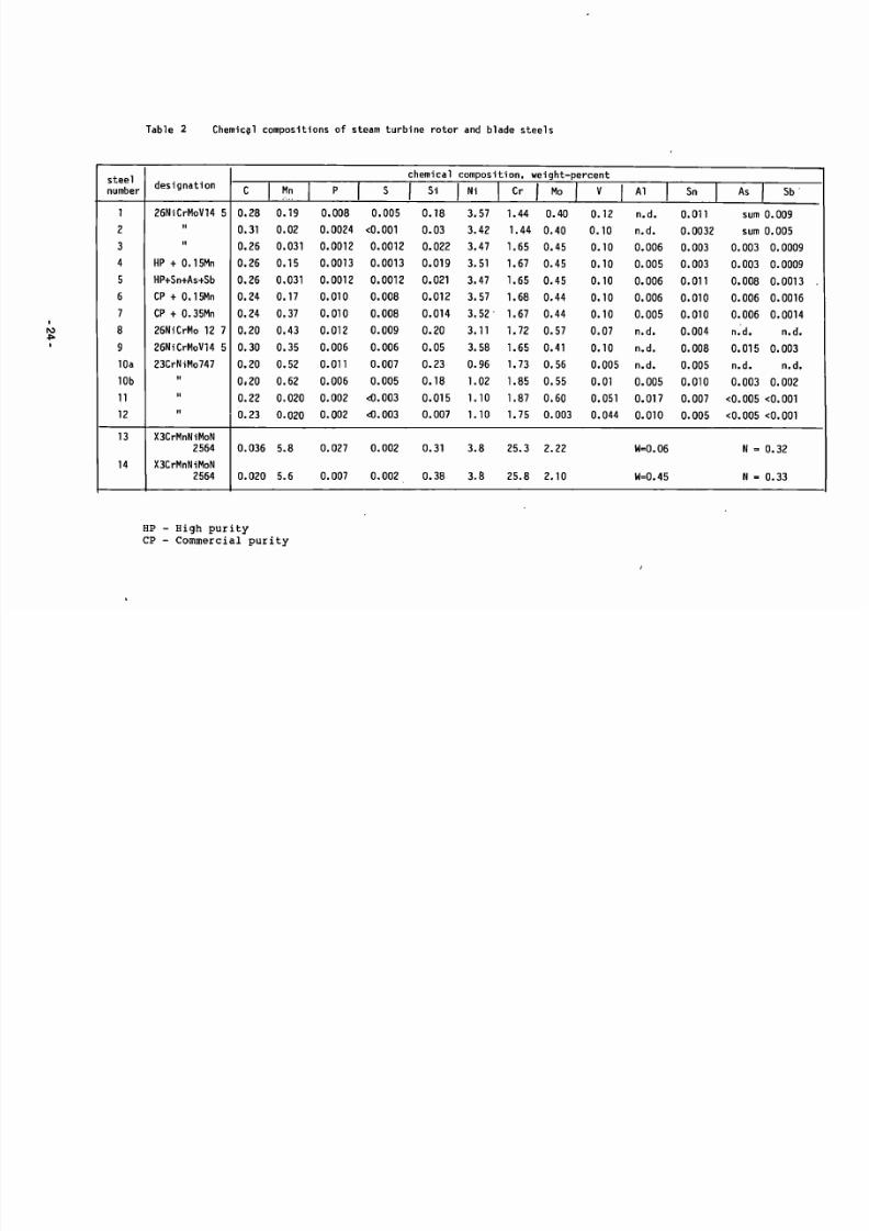
2. Chemical compositions of the steels investigated
Most of the materials investigated in the program COST 505are listed in Table 2. This includes the most widely used steamturbine rotor steels, as well as the austenitic-ferritic steel
X3CrMnNiMoN 25 6 4 which has recently been developed and modified for steam turbine blading.
The most widely employed steam turbine rotor steel is26NiCrMoV 14 5, also called 3.5NiCrMoV. Steels No. 1 and 9 inTable 2 are of this variety and were investigated by most participants of COST 505. A number of high purity versions of thissteel were also included in the joint research programs (steelsNo. 2 and 3 in Table 2 ) . A second type of LP rotor steel,23CrNiMo747, is also widely used and this as well as its high
purity versions have also been tested by a number of COST 505participants (steels 10a, 10b, 11 and 12 in Table 2 ) .
•1-

7/27/2019 SCC Evlauation by OEMS
http://slidepdf.com/reader/full/scc-evlauation-by-oems 12/84
The duplex steel for blades, as well as Its low carbon, hightungsten variety appear as number 13 and 14 in Table 2.
3. Stress corrosion cracking and corrosion fatigue
Stress corrosion cracking (SCC) is the initiation and growth
of cracks in solids under the simultaneous effects of an aggressive environment and constant or increasing tensile stresses.Corrosion fatigue (CF) is the initiation and growth of cracksunder the simultaneous effects of an aggressive environment andcyclic stresses. SCC and CF can be considered as two extremes ofa continuous spectrum of different load wave shapes as indicatedin Fig. 1. Thus, SCC and CF are two aspects of environment assisted cracking (EAC). In actual steam turbine operation therewill always be some cyclic loads on both the rotor and the blades. It is thus sometimes difficult to decide whether a particular failure is by stress corrosion cracking or corrosion fati
gue. The important question is then which failure mode is predominant. In many cases this is decided from the fracture appearance, since SCC is predominantly intergranular, along thegrain boundaries /10/, while corrosion fatigue is predominantlytransgranular across the grains and shows striations and arrestmarks /13/. However exceptions from this simplified descriptionare known.
4. Stress corrosion crack initiation
It is easy to say that all stress corrosion service failuresand stress corrosion laboratory tests include a time for crackinitiation and a time for crack growth. It is more difficult tofind out where initiation dominates and where crack growth is ofprimary importance. In service, this may depend not only on material, stress, and environment, but also on the component size.For example, a stress corrosion crack in service in a steam turbine rotor will sustain a much longer growth time before failurethan a stress corrosion crack in a steam turbine blade.
In the laboratory, two types of studies are often carriedout to study crack initiation. One type are electrochemicalstudies, in order to observe the possible reactions of a specific corrosion system, the corrosion rate and mass transferkinetics, the development and breakdown of surface films, thegrowth kinetics of local attack and so on. A second type ofstudy deals directly with stress corrosion tests of relativelysmall specimens where the overall time to failure is probablydominated by the time to crack initiation. Two such stresscorrosion tests are widely used with originally smooth specimens: constant stress or constant strain tests, hereafter calledtime-to-failure tests (TTF) and constant extension rate (CERT)

7/27/2019 SCC Evlauation by OEMS
http://slidepdf.com/reader/full/scc-evlauation-by-oems 13/84
tests. These methods and their results concerning stress corrosion crack initiation will be discussed in turn.
4.1 Corrosion pits, micro-cracks and macro-cracks
In order to simulate a typical low pressure turbine operating environment, SCC tests were carried out in pure low oxygencondensing steam at 95°C /26,28/. The result is summarized inFig. 2. The process of stress corrosion crack initiation in3.5NiCrMoV steels exposed to a steam turbine environment comprises a number of stages. The first is the nucleation and development of localised pitting attack typically, but not exclusively,at the sites of surface breaking non-metallic inclusions.
This is followed by the formation of micro-cracking at thebase of certain pits, after an incubation period but still at an
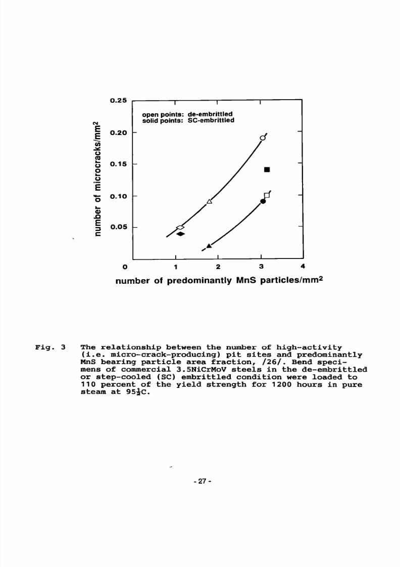
early stage of component/specimen life (Fig.2). Micro-cracks donot nucleate at all pits, and their occurrence appears to becritically dependent on the electrochemical nature of the locally contained environment and on stress concentration characteristics. In 3.5NiCrMoV steels, micro-cracking tends to be mainlyassociated with those pits originating at surface-breaking MnSparticles. The relation between the MnS inclusions in the steeland the microcracks observed in stressed specimens is illustrated in Fig. 3.
Typical micro-crack sizes are 0.1 to 0.2 mm. Finally themicro-cracks so formed may become effectively non-propagating oralternatively extend, either as single cracks or more usually bya defect interaction mechanism to a size responsible for failure. Stress corrosion crack initiation was defined as the observation of a macro-crack with a surface breaking length of about1 mm.
Factors affecting the specific behaviour may be the inclusion characteristics, the strength level of the steel, theapplied stress, and the chemistry of the bulk environment /26/.
In the COST 505 framework, crack initiation studies have beenconcentrated on steels of the type 26NiCrMoV14 5, Table 2. Concerning the inclusion characteristics, there is evidence to support the view that the stress corrosion crack initiation resistance of super clean 3.5NiCrMoV may prove to be superior to thatof conventional rotor steels due to the lower density of inclusions and the virtual elimination of MnS containing particles inthis class of steel /28/. Concerning the effect of appliedstress on crack initiation, Fig.2 appears to be substantiated byresults from more than one laboratory. The main data base comesfrom Ref./26/ and /28/. In conjunction with Fig.4 it can be
characterized as follows: for condensing steam at 95°C, preparedfrom deionized feedwater with an oxygen concentration of 7 ppband a total conductivity of 0.1 uS/cm, 3.5NiCrMoV steels willdevelop micro-cracks between 2000 and 5000 hours. Macro-cracksand failures, with smooth tensile specimens and stresses atyield strength level are typically observed after several thou-

7/27/2019 SCC Evlauation by OEMS
http://slidepdf.com/reader/full/scc-evlauation-by-oems 14/84
sand hours, /12,24,26,31/ if pitting is also occurring. Crackinitiation in condensing steam in service has been observed at50 to 70 percent of the yield strength, emanating from corrosionpits /2,30/. In the laboratory, crack nuclei were found at evenlower stress levels, down to 20 percent of yield, but generally,reducing the stress level reduces the probability of crack nu-
cleation and increases the time to crack initiation /26,28/.
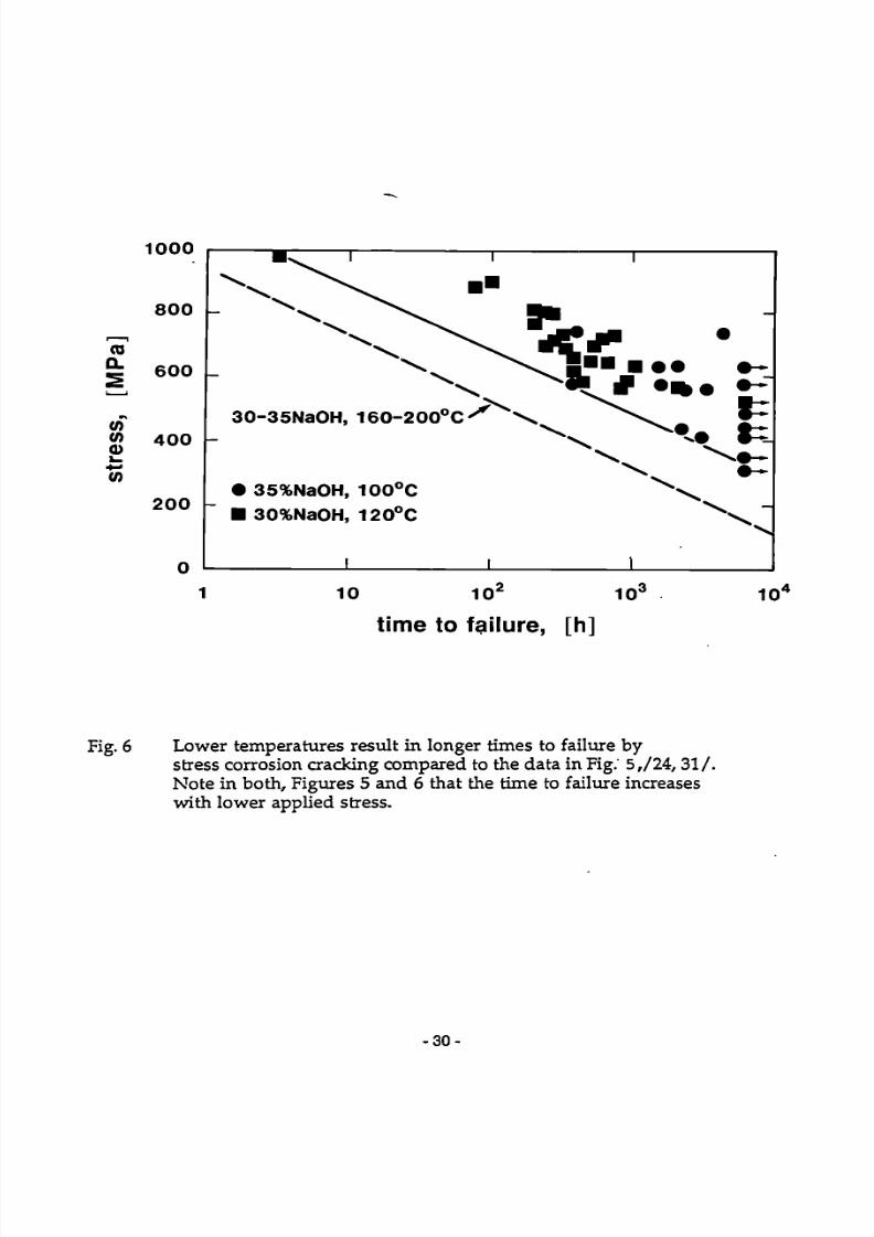
A very aggressive environment such as concentrated NaOH(which, in rare cases covers whole turbine rotors and theirblades) may cause stress corrosion cracking within hours at highstress levels (Fig.5). Such environments should therefore beavoided in service, particularly since huge stress corrosionservice failures have actually occurred with NaOH in steamturbines.
The stress dependence of the time to failure, which is apparent in Figures 5 and 6, has lead to another method to preventstress corrosion crack initiation in steam turbine rotors. Thismethod uses the introduction of compressive stresses in the surface of the shrunk-on rotor discs. The residual compressivestresses are introduced in at least three additive ways: byproper quenching during heat treatment, by shot peening of thesurfaces and by rolling of the keyway holes /8,12,19/. A typicalresult is shown in Fig.7. Note that ground specimens from COSTprogram D3 /12/ show similar times to failure to the specimensfrom COST program S1 /24/, demonstrating a much improved stress
corrosion resistance under the same conditions /12/.
4.2 Constant extension rate testing. CERT
Slow strain rate stress corrosion testing, otherwise knownas constant extension rate testing, may have some advantagesover time-to-failure testing and over crack growth rate testing.Such advantages include short testing times and the assurancethat there will always be a crack as a result of the testing.
In the present round of COST 505 the CERT test results havenot been able to contribute a lot to the understanding or to theprevention of stress corrosion cracking in steam turbines. Notall of the confusion arising from CERT testing may be attributedto this testing method itself. For example, it is stated "CERTtests in de-oxygenated 9M NaOH solution indicate the susceptibility of 3.5NiCrMoV steels to stress corrosion cracking but arenot sensitive enough to resolve the relative effect of varyingresidual element concentrations and the degree of embrittle-ment", Ref./26/. However it appears from crack growth tests,
Ref. /17/ that there is indeed no measurable effect of residualelements and temper embrittlement on SCC of steam turbine rotorsteels.

7/27/2019 SCC Evlauation by OEMS
http://slidepdf.com/reader/full/scc-evlauation-by-oems 15/84
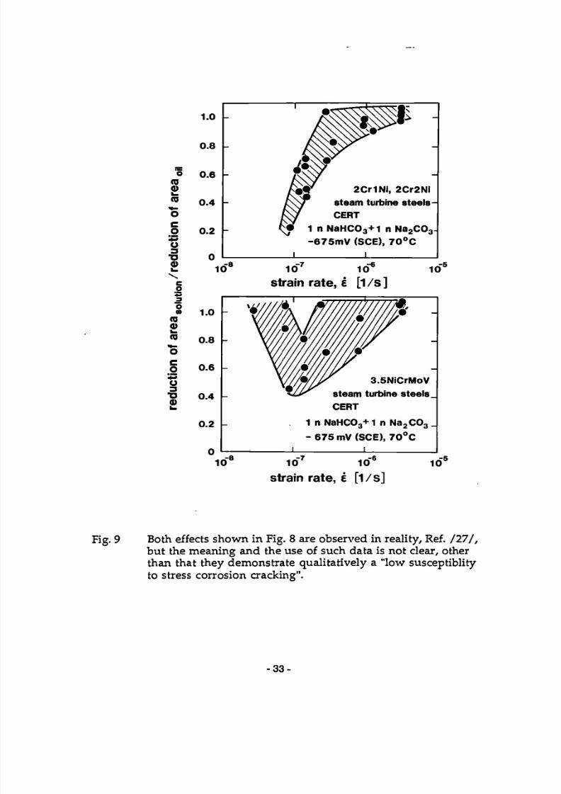
Generalized possible results from CERT-SCC tests are shownschematically in Figure 8. Actually observed data points arepresented in Figure 9. It is apparent that slow strain ratesdown to 1.5x10~7s~1 can induce stress corrosion cracking insteam turbine rotor steels in carbonate/bicarbonate solutions atan applied potential of -675 mV (SCE), and cracking occurs only
after the onset of necking in the specimens. No meaningfuldifferentiation of six various experimental rotor steels wasthereby possible, Ref./27/.
Further slow strain rate SCC tests with typical steamturbine rotor steels exposed to pure water at 160°C have beencarried out with different 0 2 and C 0 2 contents, Ref./25/. Theresults are shown in Figures 10 and 11. They confirm that theSCC part of the fracture surface is small but intergranular atlow oxygen levels; at high oxygen contents the SCC area is largebut transgranular. The C0 2 addition increases the portion ofI6SCC. A tendency to transgranular mode in oxygen-containingmedia was reported also by other authors.
The plastic deformation processes during the CER tests maychange the features of SCC and make the data transfer to realistic loading conditions difficult.
5. Stress corrosion crack propagation
It is the purpose of this section to report quantitativestress corrosion crack growth data from steam turbines, and tosingle out the major influential parameters on the crack growthrates. This chapter summarizes the results of comprehensive comparative studies concerning the stress corrosion crack growthbehaviour of steam turbine rotor steels of different chemicalcomposition, purity, and mechanical properties in hot water. Thetwelve steels of Table 2 were tested with respect to theirstress corrosion cracking resistance in water. This large groupof steels includes both the typical steam turbine rotor steels/1,8,9,10/ and a number of clean or specially alloyed steels.
The stress corrosion cracking resistance of the steels wasinvestigated by applying fracture mechanics test techniques.Stress corrosion crack growth rates have been measured on pre-cracked specimens of the double cantilever beam (DCB) or compacttension (CT) type which were provided with a fatigue precrack.Knowing the specimen geometry and the crack length, a well-defined stress intensity Kj was applied at the crack tip. Thishas been done by either using a loading frame where the load Pis applied with bolts through holes in the specimen or by
inserting a wedge into the notch, which results in a certaindeflection 6. In both cases the applied stress intensity can be
-5-
7/27/2019 SCC Evlauation by OEMS
http://slidepdf.com/reader/full/scc-evlauation-by-oems 16/84
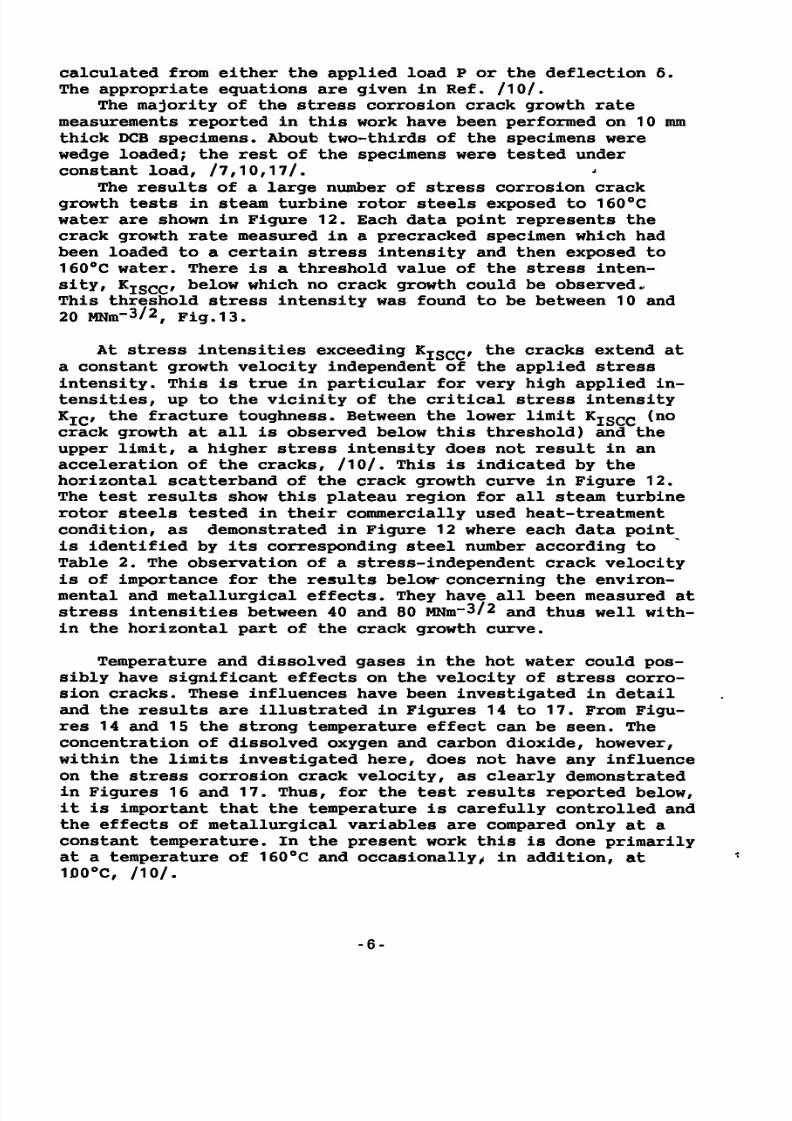
calculated from either the applied load P or the deflection 6.The appropriate equations are given in Ref. /10/.
The majority of the stress corrosion crack growth ratemeasurements reported in this work have been performed on 10 mmthick DCB specimens. About two-thirds of the specimens werewedge loaded; the rest of the specimens were tested under
constant load, /7,10,17/. -The results of a large number of stress corrosion crackgrowth tests in steam turbine rotor steels exposed to 160°Cwater are shown in Figure 12. Each data point represents thecrack growth rate measured in a precracked specimen which hadbeen loaded to a certain stress intensity and then exposed to160°C water. There is a threshold value of the stress intensity, KISCC, below which no crack growth could be observed..This threshold stress intensity was found to be between 10 and20 MNm-3/2, Fig.13.
At stress intensities exceeding KISCC, the cracks extend ata constant growth velocity independent of the applied stressintensity. This is true in particular for very high applied intensities, up to the vicinity of the critical stress intensityK IC, the fracture toughness. Between the lower limit Kjscc (no
crack growth at all is observed below this threshold) and theupper limit, a higher stress intensity does not result in anacceleration of the cracks, /10/. This is indicated by thehorizontal scatterband of the crack growth curve in Figure 12.The test results show this plateau region for all steam turbinerotor steels tested in their commercially used heat-treatmentcondition, as demonstrated in Figure 12 where each data pointis identified by its corresponding steel number according toTable 2. The observation of a stress-independent crack velocityis of importance for the results below concerning the environmental and metallurgical effects. They have all been measured atstress intensities between 40 and 80 MNm~3/2 and thus well within the horizontal part of the crack growth curve.
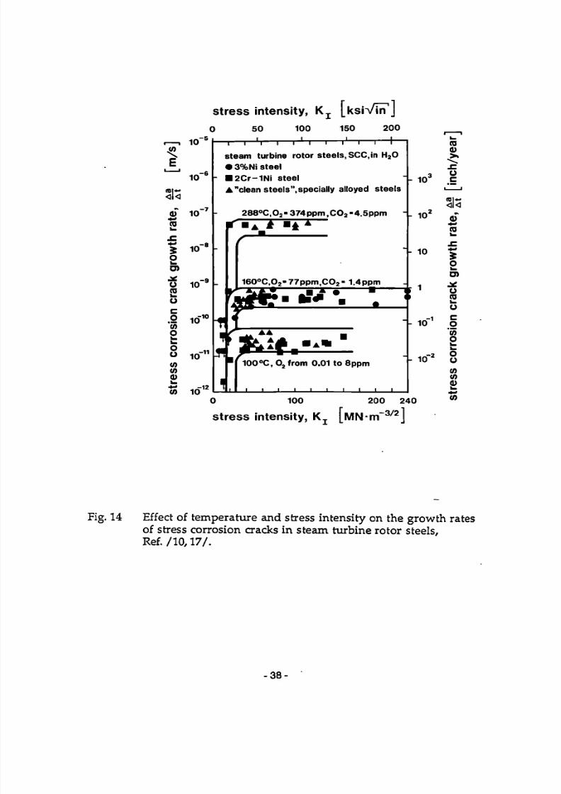
Temperature and dissolved gases in the hot water could possibly have significant effects on the velocity of stress corro
sion cracks. These influences have been investigated in detailand the results are illustrated in Figures 14 to 17. From Figures 14 and 15 the strong temperature effect can be seen. Theconcentration of dissolved oxygen and carbon dioxide, however,within the limits investigated here, does not have any influenceon the stress corrosion crack velocity, as clearly demonstratedin Figures 16 and 17. Thus, for the test results reported below,it is important that the temperature is carefully controlled andthe effects of metallurgical variables are compared only at aconstant temperature. In the present work this is done primarilyat a temperature of 160°C and occasionally, in addition, at100°C, /10/.
-6-

7/27/2019 SCC Evlauation by OEMS
http://slidepdf.com/reader/full/scc-evlauation-by-oems 17/84
If temperature and yield strength are very similar, thensimilar stress corrosion crack growth rates are observed bydifferent investigators and different laboratories. This hasalready been demonstrated in Figures 15, 16 and 17 and it isapparent again in Figure 18, where the main data base is fromRef. /17/, but data from Ref./23/, /27/, /and /31/ agree very
well, regardless of oxygen or carbon dioxide concentration.
5.1 Effects of steel composition on SCC growth rates
Figures 19 to 24 illustrate that within the limits of thealloy compositions listed in Table 2, there is no measurableeffect of the concentration of phosphorous, manganese, silicon,molybdenum, nickel and sulphur on the growth rate of stresscorrosion cracks in low alloy steels when exposed to hot water.Not all of these elements were studied in a controlled way, i.e.
changing the concentration of one element while all others wereheld constant. Nevertheless, according to Table 2, there is anumber of steels which are directly comparable with respect totheir chemical composition except for one element (for example,number 3 and 4, number 6 and 7, numbers 11 and 12, etc.). Thus,possible synergistic effects of alloying elements appear to beruled out by this direct comparison. For the turbine rotorsteels, it is fair to say that neither the cleanliness nor thebase composition of the low alloy steels used for steam turbinerotors has any significant influence on the growth of stresscorrosion cracks in these steels when exposed to hot water.
Furthermore, the series of Figures 19 to 24 illustratesagain how well the crack growth rate data from Ref. /23,27,31/agree with the main data base from Ref. /10/ and /17/.
5.2 Effect of mechanical properties on SCC growth rates
Three mechanical characteristics of the steam turbine rotorsteels have been studied with respect to their influence on the
stress corrosion crack growth rates: fracture toughness, temperembrittlement and yield strength. The results of these investigations are shown in Figures 25 to 28.
The fracture toughness of the steels can be varied in atleast three different ways, namely by the sulphur content, bytemper embrittlement and by heat treatment, i.e. yield strength.For the present investigation, the first two ways have resultedin fracture toughness values ranging from 110 to 268 MNm~3/2.The different sulphur contents of these steels investigated leadto room temperature fracture toughness values from 196 MNm~3/2up to 268 MNm~3'2. As to temper embrittlement, a commercial ro-
-7-

7/27/2019 SCC Evlauation by OEMS
http://slidepdf.com/reader/full/scc-evlauation-by-oems 18/84
tor steel (number 9 in Table 2) was available in three embritt-lement conditions. One was the "as-received" condition, with afracture toughness of 200 MNm~3/2 measured at room temperature.The other was "as received and step cooled", a heat treatmentwhich resulted in a fracture toughness of 197 MNm~3/2. The thirdcondition simulated a long time operation within the critical
temperature interval by tempering the steel at 450°C for 10'000hours. The resulting room temperature fracture toughness was110 MNm~3/2. Specimens in all three conditions were supplied aspart of the cooperation with COST 505 partner D5.
Figure.25 illustrates the effect of fracture toughness onthe stress corrosion crack growth rates. It appears that withinthe range investigated, the fracture toughness has no influenceon the growth rates of stress corrosion cracks as long as theyield strength levels do not differ considerably. This corresponds to the experimental results from Figure 24 which show thatthe bulk sulphur content does not affect the stress corrosion
crack growth rates. Temper embrittlement itself does not influence the growth rates of stress corrosion cracks in hot water,as shown in Figure 26. Note that the plateau stress corrosioncrack velocities are very nearly the same regardless of the degree of temper embrittlement. This finding is closely related toFigure 19 which demonstrates that phosphorous segregated to thegrain boundaries has no effect on the crack growth rates.
Yield strength however has a pronounced impact on stresscorrosion crack growth rates in steam turbine rotor steels. This
is illustrated in Figures 27 and 28 where the stress corrosioncrack growth rates of rotor steels with different yield strengthlevels are plotted versus stress intensity and versus yieldstrength. According to Figure 28 the effect of yield strength onthe growth rates of stress corrosion cracks depends on the absolute level of the yield strength. At all testing temperatures,there is a moderate increase of the crack growth rates for yieldstrengths between 600 and 1000 MPa, and a steep increase of thecrack growth rate once the yield strength exceeds 1000 MPa. Bothclean and commercial steels exhibit the same yield strength dependance. Similar conclusions have been reached in Ref./31/.
An extensive discussion of these experimental results including a comparison with results from other laboratories ispresented in Ref./10/.
6. Stress corrosion crack branching
The great majority of steam turbine rotor stress corrosionservice failures are due to intergranular cracking along thegrain boundaries, /10/. Such cracks are always branched on amicroscopic scale. More interesting is the observation that suchservice failures also exhibit crack branching on a macroscopic
-8-

7/27/2019 SCC Evlauation by OEMS
http://slidepdf.com/reader/full/scc-evlauation-by-oems 19/84
scale, that is at least two crack branches which grow independently over many grain diameters. Such macroscopic crackbranching reduces the stress intensity at each branch comparedto a system with a single crack of the same length. This situation has been analyzed theoretically and experimentally and the
results are given in Figures 29 and 30, /33/. Note that thestress intensity at branched crack tips decreases (compared tosingle cracks) by a factor of l/Vn when n crack branches exist,Fig.29. With such a reduced stress intensity, branched cracksmay grow deeper before the critical stress intensity (fracturetoughness) is reached. Theoretically, the critical crack lengthof an n-fold branched cracking system can be n times longer thana single crack.
This is probably an upper limit and should not be fullyused. Nevertheless, if branched cracks may grow deeper before
becoming critical, this means that the residual lifetimes ofcomponents containing branched cracks will be longer than theresidual lifetimes of the same components containing only onesingle crack of the same depth, /33/.
These ideas have been verified experimentally on specimensfrom steam turbine rotors containing branched stress corrosioncrack systems, /20/. The observations are illustrated in Fig.31,showing that the stress intensities at branched cracks are indeed reduced when the number n of branches is increased, aswould be predicted from theory and experiment, /33/.
7. Corrosion fatigue crack initiation
7.1 Corrosion fatigue crack initiation in LP rotor steels
High cycle fatigue crack initiation results from cyclicstresses below the yield strength of the material. Fatiguecracks initiate at points of maximum local stress and minimumlocal strength. In inert environments a good correlation between
the fatigue strength and the tensile strength can be found.Stress concentrations are caused by the design and manufacturingaspects ( including technological influences such as roughnessand residual stresses) and by the microstructure of the material. Microstructural inhomogeneities such as slip bands withextrusion / intrusion pairs, grain or twin boundaries, inclusions or segregations can be the initiation sites of fatiguecracks.
Corrosion fatigue must be understood as the degradation ofthe fatigue strength due to the effect of an environment. Thisincludes both the reduction of fatigue strength when the aggressive medium is present and the reduction due to the surfacedamage after corrosion attack. In contrast to inert environ-

7/27/2019 SCC Evlauation by OEMS
http://slidepdf.com/reader/full/scc-evlauation-by-oems 20/84
ments, the time-dependent corrosion processes which are superposed on the pure fatigue loading lead to a pronounced frequencydependence. Another consequence is that an endurance limit offerritic steels can not be observed under corrosion fatigue conditions. It should be noted that the increase of the nominalstresses due to the reduction of area is usually different in
laboratory specimens and in xeal components.
Fatigue investigations are mostly carried out on push / pullfatigue machines or alternating bending machines in single steptests (constant load amplitude) with the fracture of the specimens as the failure criterion. The test duration is a compromisebetween technical and economical demands and is usual limited toabout 10 7 to 10 8 cycles.
Due to the large number of parameters influencing the corrosion fatigue behaviour, it is difficult to compare the resultsof investigations which were not performed under exactly thesame conditions. In order to examine the environmental effect,the reported data concerning the LP steels are normalized andthe ratios of the fatigue strength levels in corrosion mediumand in air are considered. As it can be seen from Figure 32,which presents the data of the COST programs /16,17/, the reduction of the strength level in deaerated pure water up to160°C is about 25% of the endurance limit in air at room temperature. In the case of oxygen saturation a much larger effectwas observed although no severe surface attack occurred. In both
cases we are concerned with a passive corrosion system, but thehigher content of oxidation agent obviously results in an earlier nucleation of fatigue cracks at the local sites of filmrupture. Slip bands which penetrate the passive layer are suchsites of film-free ( and therefore unprotected) metal and willbe more strongly attacked if the oxidation potential is high.In contrast to oxygenated water the breakdown potential in aerated water is lowered due to the effect of pH reduction (causedby the C0 2 and by atmospheric pollution) and so the level offatigue strength is additionally reduced by the stress concentrations at the pits and flaws. The same fatigue strength as in
aerated water was measured if the surface damage was produced ina precorrosion step and the tests were carried out in oxygenatedwater. This demonstrates that the difference between aerated andoxygenated water is caused by the mechanical notch effect.
In order to investigate the pure mechanical effect of different forms of corrosion attack, precorroded specimens were fatigued in air and related to the fatigue strength of virgin specimens (Figure 33). It can be seen that pure deaerated water doesnot produce any surface damage which leads to a reduction of the
fatigue strength. After exposure in an acid environment, whichled to homogeneous corrosion, the fatigue strength level islowered by about 20%. In the case of local corrosion, the reduc-
10-
7/27/2019 SCC Evlauation by OEMS
http://slidepdf.com/reader/full/scc-evlauation-by-oems 21/84
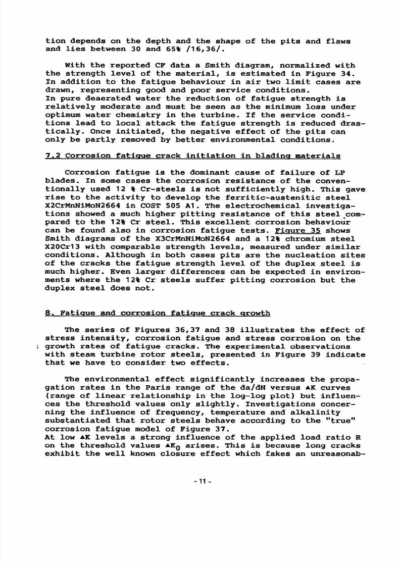
tion depends on the depth and the shape of the pits and flawsand lies between 30 and 65% /16,36/.
With the reported CF data a Smith diagram, normalized withthe strength level of the material, is estimated in Figure 34.In addition to the fatigue behaviour in air two limit cases are
drawn, representing good and poor service conditions.In pure deaerated water the reduction of fatigue strength isrelatively moderate and must be seen as the minimum loss underoptimum water chemistry in the turbine. If the service conditions lead to local attack the fatigue strength is reduced drastically. Once initiated, the negative effect of the pits canonly be partly removed by better environmental conditions.
7.2 Corrosion fatigue crack initiation in blading materials
Corrosion fatigue is the dominant cause of failure of LPblades. In some cases the corrosion resistance of the conventionally used 12 % Cr-steels is not sufficiently high. This gaverise to the activity to develop the ferritic-austenitic steelX2CrMnNiMoN2664 in COST 505 A1. The electrochemical investigations showed a much higher pitting resistance of this steel compared to the 12% Cr steel. This excellent corrosion behaviourcan be found also in corrosion fatigue tests. Figure 35 showsSmith diagrams of the X3CrMnNiMoN2664 and a 12% chromium steelX20Cr13 with comparable strength levels, measured under similarconditions. Although in both cases pits are the nucleation sites
of the cracks the fatigue strength level of the duplex steel ismuch higher. Even larger differences can be expected in environments where the 12% Cr steels suffer pitting corrosion but theduplex steel does not.
8. Fatigue and corrosion fatigue crack growth
The series of Figures 36,37 and 38 illustrates the effect ofstress intensity, corrosion fatigue and stress corrosion on the
growth rates of fatigue cracks. The experimental observationswith steam turbine rotor steels, presented in Figure 39 indicatethat we have to consider two effects.
The environmental effect significantly increases the propagation rates in the Paris range of the da/dN versus AK curves(range of linear relationship in the log-log plot) but influences the threshold values only slightly. Investigations concerning the influence of frequency, temperature and alkalinitysubstantiated that rotor steels behave according to the "true"corrosion fatigue model of Figure 37.
At low A K levels a strong influence of the applied load ratio Ron the threshold values A K Q arises. This is because long cracksexhibit the well known closure effect which fakes an unreasonab
le
7/27/2019 SCC Evlauation by OEMS
http://slidepdf.com/reader/full/scc-evlauation-by-oems 22/84
ly high A K Q threshold. Considering these details, one can drawthe following conclusion from the work upon which Figure 39 isbased, /16,37/:
For the consideration of short defects, such as corrosionpits, the threshold of the closure-free region (high R ratio)should be applied regardless of the effective mean stress. ThisAKg value was found to be about 2 MPaVm.
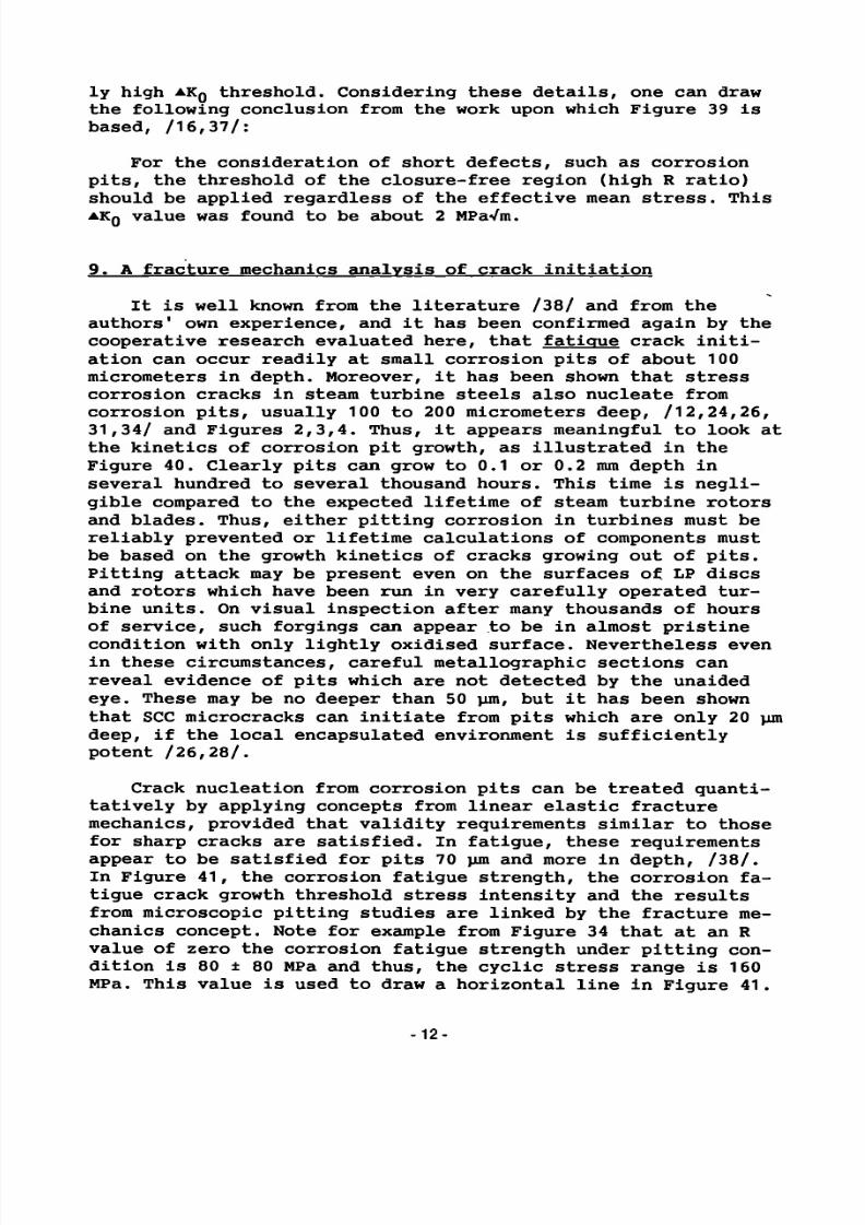
9. A fracture mechanics analysis of crack initiation
It is well known from the literature /38/ and from theauthors' own experience, and it has been confirmed again by thecooperative research evaluated here, that fatigue crack initiation can occur readily at small corrosion pits of about 100
micrometers in depth. Moreover, it has been shown that stresscorrosion cracks in steam turbine steels also nucleate fromcorrosion pits, usually 100 to 200 micrometers deep, /12,24,26,31,34/ and Figures 2,3,4. Thus, it appears meaningful to look atthe kinetics of corrosion pit growth, as illustrated in theFigure 40. Clearly pits can grow to 0.1 or 0.2 mm depth inseveral hundred to several thousand hours. This time is negligible compared to the expected lifetime of steam turbine rotorsand blades. Thus, either pitting corrosion in turbines must bereliably prevented or lifetime calculations of components mustbe based on the growth kinetics of cracks growing out of pits.
Pitting attack may be present even on the surfaces of LP discsand rotors which have been run in very carefully operated turbine units. On visual inspection after many thousands of hoursof service, such forgings can appear to be in almost pristinecondition with only lightly oxidised surface. Nevertheless evenin these circumstances, careful metallographic sections canreveal evidence of pits which are not detected by the unaidedeye. These may be no deeper than 50 urn, but it has been shownthat SCC microcracks can initiate from pits which are only 20 umdeep, if the local encapsulated environment is sufficientlypotent /26,28/.
Crack nucleation from corrosion pits can be treated quantitatively by applying concepts from linear elastic fracturemechanics, provided that validity requirements similar to thosefor sharp cracks are satisfied. In fatigue, these requirementsappear to be satisfied for pits 70 um and more in depth, /38/.In Figure 41, the corrosion fatigue strength, the corrosion fatigue crack growth threshold stress intensity and the resultsfrom microscopic pitting studies are linked by the fracture mechanics concept. Note for example from Figure 34 that at an R
value of zero the corrosion fatigue strength under pitting condition is 80 ± 80 MPa and thus, the cyclic stress range is 160MPa. This value is used to draw a horizontal line in Figure 41.
12-

7/27/2019 SCC Evlauation by OEMS
http://slidepdf.com/reader/full/scc-evlauation-by-oems 23/84
Furthermore, based on Figure 39, a corrosion fatigue thresholdstress intensity of about AK = 2 MPaVm is established, dependingon the exact definition of that threshold (We may take it tocorrespond to AK which gives crack growth rates of 10~11 or5x10~1^ meters per load cycle). This threshold A K = 2 MPaVm isshown as a diagonal line in Figure 41. The lines 160 MPa and 2
MPaVm intersect at a point which corresponds to a=10
-
^ m. Thismeans that whenever pits develop into crack-like shapes of about0.1 mm depth, the fatigue threshold stress intensity is exceededat a cyclic stress range of 160 MPa. This is the reason for thelow corrosion fatigue strength which is manifest in Figures 32to 34. It is also the reason for the similarity of the corrosionfatigue strength of steam turbine rotor and steam turbine bladematerials under pitting conditions.
Figure 41 permits also a quantitative evaluation of stresscorrosion crack nucleation from corrosion pits. Note for example
in Figure 13 that stress corrosion threshold stress intensitiesof steels exposed to water are generally between 10 and 20MPaVm. The lower bound value of K = 10 MPaVm has been used todraw a diagonal line in Figure 41. Above it stress corrosioncracking might occur. This line intersects the 800 MPa line(representing typical yield strengths of steam turbine rotorsteels) at a point corresponding again to 10 -^ m. One may conclude from this that steam turbine rotor steel under stressesnear the yield strength and exposed to hot water can developstress corrosion cracks once crack-like pits reach a depth of100 micrometers. This is in agreement with all the pitting andstress corrosion studies carried out in the cooperative COST 505research program. Naturally these values are only approximations. If, for example pits would reach a depth of 400 micrometers then, according to Figure 41, stress corrosion crackscould start growing even if the applied stress were only 400MPa, i. e. half the yield strength.
10. Considerations concerning the mechanisms of SCC
Based on the COST 505 work, in this section an attempt ismade to understand the chemical mechanisms of stress corrosioncracking.The driving force for every corrosion process is the thermodynamic instability of the metal in a given environment. If thereactions, which lead to more stable products, are blocked (forexample by a protecting film) the system will exhibit local corrosion as soon as the barrier is destroyed locally. In this casein addition to the material and the environment a third component of the corrosion system becomes more important: the mechanical loading.
-13-

7/27/2019 SCC Evlauation by OEMS
http://slidepdf.com/reader/full/scc-evlauation-by-oems 24/84
Before considering the COST 505 results the corrosion system: low alloyed steel / water, i.e. iron / water should be described briefly: At surfaces of low alloyed steels exposed to pure neutral or weakly alkaline water, hydroxide or oxide films develop. Ini-tially an amorphous Fe(OH)2 film grows, which converts after-
wards to magnetite (Fe304) according to the Schikorr reaction. The velocity of this reaction is very low at ambient temperatu-re;, above 100 °C its rate is noticeable and above 230 °C spon-taneous formation of magnetite takes place /41,42/. In acid en-vironments the iron goes into solution as the Fe2+ ion and in strongly alkaline media the complex ion Fe02H~ is formed.
The cathodic reaction in pure water is always the develop-ment of hydrogen from protons if no oxygen or other oxidizing agents are present. Local forms of corrosion appear when the breakdown potential of the passive films is exceeded. This breakdown potential is main-ly influenced by the kind and concentration of film destroying ions (such as chlorides), by the temperature and the pH value /43/.
It is well known that the stress concentration caused by pits can reduce the fatigue strength level of a material drastically. The COST 505 work on SCC initiation has focussed interest on the nucleation and growth of pits also as a prior step to stress corrosion cracks. Pits, micro- and macro-cracks were found in specimens exposed to
condensing pure steam. These results shall be considered toge-ther with other investigations in order to come to a consistent model.
In /16/ measurements in a closed autoclave system were carried out. Although the conductivity increased considerably during the tests no indications of growing pits were found. Similar results are reported after long term exposure /31/; neither in deaerated nor in oxygenated water was localized attack observed. This means that water as a bulk environment is much less aggressive than condensing steam although its content of impurities might be higher than those of the feed
water of the steam cycle. It is well known that the content of impurities in the first condensate can be much higher than in the steam, depending on the distribution coefficient of the agent. However the results of /31/ showed that a high content of impurity is not absolutely necessary to understand crack nucleation. Typical intergranular SCC appeared if the environments were not refreshed or if crevice conditions were applied, i.e. if stag-nated conditions were present. Obviously condensate films are comparable to those stagnating environments.
Under stagnating conditions the requirements are given for the development of concentration elements at an inhomogeneous metal surface (surface-breaking inclusions, inhomogeneous passive
■14-

7/27/2019 SCC Evlauation by OEMS
http://slidepdf.com/reader/full/scc-evlauation-by-oems 25/84
film, mechanical defects or crevices with the possibility of thedevelopment of ventilation elements) and so for the appearanceof stable anodic and cathodic zones. Due to hydrolysis of thecorrosion products the aggressivity of the local environment atthe anodic zones may increase whereas the cathodic regions areinhibited by an increase in pH value at the wall.
The pit depth increases according to a logarithmic time law;i.e. the growth rate decreases because a saturation of the pitelectrolyte with metal ions takes place and the mass transfer ishindered more strongly if the diffusion distances to the bulksolution are larger. The shape of the pits, which is usuallymore or less hemispherical, can change if tensile stresses arepresent. In /26/ it was observed that certain pits showed highergrowth rates at the tip of the pit than at the side walls; thismeans the shape of such pits tends to become crack-like. Thedensity of these "high activity pits" increases with the applied
stress. The stress concentration at the pit tip seems to activate this zone whereas the side walls repassivate.The final stage of this process is the development of micro-cracks at the activated pit tip. A necessary assumption for theformation of crack is that the growth rate of the pit is nothigher than that of the crack. Obviously the transition takesplace if the current densities at the pit tip and the tip of theintergranular SCC crack are of the same order.
The experimental findings of crack initiation at anodic zo
nes point to an anodic mechanism of crack growth. The fact, thatthe SCC rate is less influenced by the composition of the bulksolution, by the load level and the crack geometry (diffusiondistances) indicate the development of a local corrosion system.This system is characterised by a local crack tip environmentwhich repassivates the crack flanks immediately after crack propagation.
The SCC propagation in high-strength material is often explained by a hydrogen mechanism. Atomic hydrogen, which is developed by the cathodic partial reaction of the corrosion, can be
absorbed by the metal lattice. It diffuses to so-called hydrogentraps (grain boundaries, dislocations or other defects of thelattice structure) and embrittles the material.Although investigations are still necessary to clarify themechanism in detail some remarks can be made:
Of course the plastic zone in front of the crack tip, withits microstructural defects, is a highly active hydrogen trap,and the energy to crack an embrittled material is lower. Howeverthe model of pure hydrogen induced cracking (HISCC) seems not tobe applicable. This becomes evident in the inhibition of SCC
propagation after cathodic polarisation /44,45/. According tothe classical model of HISCC, cracking is caused by the activity
-15-

7/27/2019 SCC Evlauation by OEMS
http://slidepdf.com/reader/full/scc-evlauation-by-oems 26/84
of hydrogen in the lattice regardless of where the hydrogencomes from, i.e. it is independent of an anodic reaction.The embrittlement by hydrogen of LP rotor steel should be seenas an "alloying effect" which changes the properties of thematerial and which has a crack accelerating effect. It is notheld for the causal reason of crack propagation in diluteaqueous environments (even for high strength materials).
From the result that pitting and SCC can appear in pure lowoxygen steam at relatively low load levels one could concludethat all rotors exhibit SCC microcracks. Since the microcracksand the pits, at which these cracks are initiated, are too smallfor a visual inspection or for non-destructive test methods thisconclusion can hardly be verified. However the development ofmacrocracks, which were found in the experiments after some tensof thousands of hours at high load levels, does not agree withthe experiences in many stations. Therefore in the following
some ideas concerning possible differences between the laboratory and the service environments shall be outlined:
- In the laboratory tests the conductivity of the feedwater forthe steam generation was carefully controlled and held at alow level. The conductivity is a general measure for the sumof all ion impurities contained in the water; the aggressi-vity of the condensate phase however depends on the kind andthe distribution coefficient of these impurities.Additionally non-ion agents, which are not measured by aconductometer, can produce aggressive environments in the
steam cycle. This means that we cannot exclude differenteffects of media with the same low conductivities.
- Specific impurities in the steam cycle of a power plant can bedeposited in the dry part of the HP and IP and hence be missing from the LP environment (specially if a closed loop isinstalled).In the laboratory tests the steam is condensed directly inthe specimen chamber and then discarded. The effect mentionedabove is not possible.
- Steam in power plants is doped with alkalisation agents. Anincreased pH in the condensate shifts the pitting potentialto higher values and makes the occurrence of pits lessprobable.
- The velocity of steam flow is much higher in the turbine thanin the test rig. This may decrease the possibility of thedevelopment of concentration elements at the steel surface(thinner condensate films; more turbulent flow with betterexchange between steam and condensate phase).
•16-

7/27/2019 SCC Evlauation by OEMS
http://slidepdf.com/reader/full/scc-evlauation-by-oems 27/84
- The position of the first condensate depends on the operating conditions. Locally established corrosion systems can be dryed out or washed away.
In order to minimise local forms of corrosion in LP rotors all actions which increase the difference between the breakdown
potential and the open circuit potential and which eliminate stagnating environments are welcome.
- Due to a low content of impurities in the feedwater the dan-ger of the enrichment of the film-destroying agents in the condensate decreases and results in a higher breakdown poten-tial. The measurement of the conductivity is a simple and robust method to monitor the impurity level. Since a low conduc-tivity alone is no guarantee for a low aggressivity further analyses and sporadic inspections during standstills are
necessary to ensure a sufficient steam quality.
- The reliable alkalisation of the condensate film increases the breakdown potential. It should be remarked that the pH of the first condensate phase can be quite different from the pH of the bulk condensate.
- The open circuit potential is based on the equilibrium of the anodic and cathodic reactions and so on the kind and concen-tration of oxidizing agents. Oxygen is present in the LP turbine only during a trip, not during normal operation. If no other oxidizing impurity is present the open circuit potential is dependent on the HjO"1" / H2 - reaction, i. e. on the pH. The lower the H30 + concentration (= the higher the pH) the lower the open circuit potential.
- During shutdown phases condensing moisture in the presence of air (and the air pollutants) can produce environments of high aggressivity. The turbine should be kept dry during this time.
11. Conclusions
The cooperative research program COST 505 has achieved sig-nificant progress in the field of stress corrosion cracking and corrosion fatigue of steam turbine rotor and blade materials.
The central role of pitting as nucleation sites for stress corrosion and corrosion fatigue cracking has been demonstrated. It is therefore clear that the prevention of pit formation is a worthwhile goal, although in practical terms the total elimina-
tion of this form of attack may be impossible to achieve. Nevertheless, both stress corrosion a n d ^ õ a ^ ú n fatigue crack
■ 17-

7/27/2019 SCC Evlauation by OEMS
http://slidepdf.com/reader/full/scc-evlauation-by-oems 28/84
initiation processes are statistical events and any steps takento minimise the incidence of pitting will markedly reduce theprobability of these two forms of environmental cracking. Theresults of the COST 505 collaboration have shown that suchmeasures include the adoption of steels with low volume fractions of non-metallic inclusions, the avoidance of surface resi
dual tensile stresses during the final stage of manufacture, theminimisation of the static and dynamic service stresses, thelimitation of the strength levels of the applied materials andthe avoidance of crevices and stagnating conditions.
Ah important contribution can be provided by the water chemistry. The impurities contained in the steam cause either deposits in the dry part of the turbine (with subsequent increase ofthe steam consumption and possible corrosion during the shutdowns) or an aggressive environment in the first condensate.A correct supervision of the medium purity, consisting of the
immediate detection of any contamination and the quick application of corrective actions, can minimise the risk of environmental induced failures.
The aggressivity of the environment in a steam / water loopis hardly predictable because it is dependent on the quality ofthe chemical supervision, thus on decisions made by the operators. So the quality of the chemical supervision, whichdetermines the medium purity, should be evaluated periodicallyby a specialist. The inspections should include:
- On-line check of the chemical parameters and of the monitoring equipment
- Inspection of the equipment during overhauls. This observation should check the cleanness of the turbine and theheat exchangers and allow a quantification of any depositsand / or of corrosion in the system.
Since pit formation is often related to sporadic abnormalservice conditions and since pits can stop propagation due to achanged environment, a lifetime calculation is not possible in
advance. Such calculations are meaningful if cracks have alreadyappeared because their growth kinetic are less influenced by thebulk medium and can be described using fracture mechanics.
Despite the advances in understanding the mechanism of SCCinitiation and propagation there are still open questions concerning the environmental conditions required in order to besure of avoiding pit nucleation. For a more detailed quantitative fracture mechanics analysis, threshold stress intensitymeasurements and pitting kinetics studies need further refinement.
'A18-
7/27/2019 SCC Evlauation by OEMS
http://slidepdf.com/reader/full/scc-evlauation-by-oems 29/84
The development of an austenitic-ferritic blading steel withconsiderably higher corrosion fatigue resistance than the conventional 12% Cr steel was successfully finished. This materialis applicable to blading designs which do not require a yieldstrength above 600 MPa or the induction hardening of the leadingedges.
12. Acknowledgement
This study has been conducted with the financial assistanceof the Commission of the European Communities, under contractno. COST -0010-CH (CH).
13. References
/1/ Kalderon, Proc.Instn.Meen.Engrs., Vol.136, 1972, pp 341-377Steam Turbine Failure at Hinkley Point A
/2/ Hodge, Mogford, Proc.Instn.Mech.Engrs., Vol.193, 1979,pp 93-106, UK Experience of Stress Corrosion Cracking inSteam Turbine Disks
/3/ Lindinger, Curran, Materials Performance, Feb.1982, pp 22-26Experience with Stress Corrosion Cracking in Large SteamTurbines
/4/ Lyle, Burghard, Materials Performance, Nov.1982, pp 35-44,Cracking of Low Pressure Turbine Rotor Discs in US NuclearPower Plants
IS / Lyle, McMinn, Leverant, Proc.Instn.Mech.Engrs., Vol.199,1985, pp 59-67, Low pressure steam turbine disc cracking -an update
/6/ Czajkowski, Weeks, Materials Performance, March 1983,pp 21-25, Examination of Cracked Turbine Discs from NuclearPower Plants
111 Speidel, Magdowski, Second International Symposium on Environmental Degradation of Materials in Nuclear Power Systems-Water Reactors, Monterey, CA, Sept.9-12, 1985, Stress Corrosion Cracking of Steam Turbine Steels - An Overview
/8/ Engelke, Schleithoff, Jestrich, Termuehlen, Proc. of theAmerican Power Conference, Vol.45, 1983, Design, Operating
and Inspection Considerations to Control Stress Corrosion ofLP Turbine Disks
/9/ Aubry, Duchateau, Technology of Turbine Plant Operating withWet Steam, London, 1988, French Experience of Corrosion inNuclear Turbines
/10/ Magdowski, Speidel, Metall.Trans.A., Vol.19A, 1988, pp 1583-1596, Clean Steels for Steam Turbine Rotors - Their StressCorrosion Cracking Resistance
/11/ Jaffee, Metall. Trans.A.,1986, Vol.17A, pp 755-75/12/ Schleithoff, David, Schmitz, Ewald, DVM-Arbeitskreis Bruch
vorgänge, 1988, pp 167-180, Spannungs-Risskorrosion an Tur-binenradscheiben
19-

7/27/2019 SCC Evlauation by OEMS
http://slidepdf.com/reader/full/scc-evlauation-by-oems 30/84
/13/ Hagn, "Lifetime Prediction for Parts in Corrosive Environments", in Corrosion in Power Generating Equipment,M. 0. Spei-del and A.Atrens, eds.,Plenum Press, N.Y. and London, 1984,pp 481-516
/14/ "Advances in material technology for fossil plants",Viswanathan and Jaffee, editors, ASM International, 1987
/15/ COST 505 A1, Final Report, Hochörtler et al, 1989
/16/ COST 505, CH3, Final Report, Denk, Maggi, Scarlin, 1989/17/ COST 505, CH4, Final Report, Magdowski,Speidel, 1988/18/ COST 505, D2, Final Report, David, 1988/19/ COST 505, D3, Final Report, David, 1988/20/ COST 505, D5, Final Report, Berger, 1989/21/ COST 505, D6, Final Report, Wunderlich, Schmitt-Thomas, 1989/22/ COST 505, D28, Final Report, David, 1988/23/ COST 505, 15, Final Report, Pozzi, Gabetta, 1989/24/ COST 505, S1, Final Report, Tavast, 1989/25/ COST 505, SF3, Final Report, Hietanen, 1989/26/ COST 505, UK11, Final Report, Holdsworth, Burnell, 1989/27/ COST 505, UK20, Final Report, Mclntyre, Mulvihill, Trant, 1989
/28/ S.R.Holdsworth, G.Burnell and C.Smith, "Factors influencingstress corrosion crack initiation in super clean 3.5NiCrMoVrotor steel". To be published in proceedings of EPRI-con-ference on clean steels, Japan, 1989, by ASTM, 1990
/29/ Oeynhausen et al, "Reliable Disk-Type Rotors for NuclearPower Plants", American Power Conference, Chicago, April27-29, 1987
/30/ B.W. Roberts and P. Greenfield, "Stress Corrosion of SteamTurbine Disc and Rotor Steels", Corrosion, NACE 35.(1979)pp 402-409
/31/ David, Schleithoff, Schmitz, "Spannungsrisskorrosion in hochreinem Wasser von 3 1/2% NiCrMoV-Vergütungsstählen für Dampf
turbinen-Scheiben und -Wellen", Mat.-Wiss.u.Werkstofftechnik,Vol.19, 1988, 43-50 und 95-104
/32/ Maggi, BBC internal report/33/ Ruth M.Magdowski, Peter J.Uggowitzer and Markus 0.Speidel,
"The effect of crack branching on the residual lifetime ofmachine components containing stress corrosion cracks",Corrosion Science 25 (1985) pp 745-756
/34/ Müller, "Theoretical Considerations on Corrosion FatigueCrack Inititation", Metallurgical Transactions A, Vol.13A,1982, pp 649-655
/35/ Schieferstein, Schmitz, "Korrosions-Zeitschwingfestigkeit vonTurbinenwerkstoffen unter betriebsähnlichen Beanspruchungen"VGB Kraftwerkstechnik, Vol.58, 1978, pp 193-260
/36/ T.C.Lindley, P.Mclntyre and P.J.Trant, "Fatigue crack initiation at corrosion pits". Metals Technology 9 (1982)pp 135-142
/37/ M.O.Speidel, ETH Zürich, unpublished work 1982/38/ Markus 0.Speidel and Andre Pineau, "Fatigue of high-tempe
rature alloys for gas turbines", in High-Temperature Alloysfor Gas Turbines, Applied Science Publishers, London, 1978,pp 479-512
/39/ M.O.Speidel, Corrosion Fatigue in Fe-Ni-Cr Alloys, in"Stress Corrosion Cracking and Hydrogen Embrittlement ofIron Base Alloys", NACE 5, NACE, Houston, TX, 1977, 1071-1094'
/40/ S.Sakurai et al, "Failure analysis and life assessment of lowpressure turbine blades", American Power Conference, 1989
-20-

7/27/2019 SCC Evlauation by OEMS
http://slidepdf.com/reader/full/scc-evlauation-by-oems 31/84
/41/ Härderilus, "Kenntnis der Schutzwirkung und Stabilität vonOxidschichten auf Stahl in alkalischen und neutralem Wasser",Mitteilungen des VGB, April 1966, pp 132-141
/42/ Potter, "Neue Vorstellungen über die Reaktion zwischen Stahlund Wasser bei hohen Temperaturen", Mitteilungen des VGB,February 1962, pp 19-22
/43/ Pourbaix, "Significance of Protecting Potential in Pitting
and Intergranular Corrosion", Corrosion NACE, Vol.26, 1970,pp 479-500
/44/ Congleton, Shoji, Parkins, Corrosion Science, Vol. 25, 1984,pp 633-650
/45/ Shalvey, Corrosion NACE, Vol.39, 1983, pp 66-70
-21-

7/27/2019 SCC Evlauation by OEMS
http://slidepdf.com/reader/full/scc-evlauation-by-oems 32/84

7/27/2019 SCC Evlauation by OEMS
http://slidepdf.com/reader/full/scc-evlauation-by-oems 33/84
Table 1: Projects of COST 50 5, Group 1
Project
Al
CH3
CH4
D1
D2
D3
D5
D6
D28
15
S1
SF3
UK11
UK20
Lab.
VEWKapfenb.
ABBBaden
ETHZürich
MPIDüsseid.
Siemens-KWU
Mülheim
Siemens-KWU
Siemens-KWU
Mülheim
TUMünchen
Siemens-KWU
Mülheim
CISEMilano
ABBFinspong
VTT
Tampere
GECRugby
CEGBLeatherh
Title
Advanced Materials for theFinal Stages of Steam Turbines
Failure Mechanisms in SteamTurbine Rotors
SCC of Steam Turbine RotorMaterials
Effect of P-content on Mechanical Properties andCorrosion Behavior
Corrosion Fatigue of Turbine Rotors under Operating Conditions
Influence of Residual Com
pressive Stresses on theSCC Behaviour
Crack Growth and Fractureof Stress Corrosion Cracks
Corrosion Fatigue of Duplex Steels under SimulatedTurbine Conditions
Corrosion Behaviour of theX3CrMnNiMoN2564 under Service Related Conditions
SCC Behaviour of LP Discand Rotor Materials
SCC initiation Mechanismin Steam Turbine Rotors
Stress Corrosion Cracking
of LP Rotor Steels
Stress Corrosion of LPDiscs and Rotors
Effect of Pitting and AlloyContent on SCC
Investigations
Production of test melt.Forging and heat treatment.
CF, da/dH
SCC propagationFracture mechanics
Auger investigationsSCC-
CF, Pitting
SCC initiationafter surface treat
ments
AKQ and K j C ofbranched SCC cracks
CF, Pitting
CF, SCC, Pitting
SCC propagationFracture mechanics
SCC initiation
CERT
SCC initiation
Pitting, SCC initiationand propagation, CERT
Materials
X3CrMnNiMoN2564Duplex Steel
3.5NiCrMoV
2CrlNi,2Cr2Ni
commercial, cleanexperimental rotor
steels
Various
3.5 HiCrMoV
3.5NiCrMoV
3.5NiCrMoV
X3CrMnNiMoN2564
X3CrMnNiMoN2564
3.5NiCrMoV
2Cr1Hi
3.5HiCrMoV
2Cr1Ni andother steels
3.5HiCrMoV
2Cr1Ni
3.5NiCrMoV
andembrittled
3.5NiCrMoV
experimentalsteels
Environments
-
Pure WaterRT - 160 °C(autoclave)
Pure WaterRT - 160 °C(autoclave)
~
Condensate(aerated,oxygenated)
NaOH/HaCl-solution
air
Chloride solutions, pH3-780-150°C
Chloride solutions, pH3-7
80°C
Pure water
NaOH andaeratedwater
Pure water
+ o 2, co 2(autoclave)
Pure condensing steam
95°C
Pure condensing steam
95 DC
-23-
7/27/2019 SCC Evlauation by OEMS
http://slidepdf.com/reader/full/scc-evlauation-by-oems 34/84
T ab le 2 C hem ic a l c om pos i t i ons of s te a m t u r b i n e r o t o r and b l a d e s t e e l s
steelnumber
12
3
4
5
6
7
8
9
10a
10b
11
12
13
14
designation
26NiCrMoV14 5ti
H
HP + 0.15Mn
HP+Sn+As+Sb
CP + 0.15Mn
CP + 0.35Mn
26NiCrMo 12 7
26NiCrMoV14 5
23CrNiMo747
II
II
M
X3CrHnNiMoN2564
X3CrMnNiMoN
2564
C
0.28
0.31
0.26
0.26
0.26
0.24
0.24
0.20
0.30
0.20
0,20
0.22
0.23
0.036
0.020
Mn
0.19
0.02
0.031
0.15
0.031
0.17
0.37
0.43
0.35
0.52
0.62
0.020
0.020
5.8
5.6
P
0.008
0.0024
0.0012
0.0013
0.0012
0.010
0.010
0.012
0.006
0.011
0.006
0.002
0.002
0.027
0.007
S
0.005
<0.001
0.0012
0.0013
0.0012
0.008
0.008
0.009
0.006
0.007
0.005
<0.003
<0.003
0.002
0.002
:hemical
Si
0.18
0.03
0.022
0.019
0.021
0.012
0.014
0.20
0.05
0.23
0.18
0.015
0.007
0.31
0.38
composi
Ni
3.57
3.42
3.47
3.51
3.47
3.57
3.52
3.11
3.58
0.96
1.02
1.10
1.10
3.8
3.8
tion, weight-percent
Cr
1.44
1.44
1.65
1.67
1.65
1.68
1.67
1.72
1.65
1.73
1.85
1.87
1.75
25.3
25.8
Ho
0.40
0.40
0.45
0.45
0.45
0.44
0.44
0.57
0.41
0.56
0.55
0.60
0.003
2.22
2.10
V
0.12
0.10
0.10
0.10
0.10
0.10
0.10
0.07
0.10
0.005
0.01
0.051
0.044
Al
n.d.
n.d.
0.006
0.005
0.006
0.006
0.005
n.d.
n.d.
n.d.
0.005
0.017
0.010
W=0.06
W=0.4E
Sn
0.011
0.0032
0.003
0.003
0.011
0.010
0.010
0.004
0.008
0.005
0.010
0.007
0.005
As
sumsum
0.003
0.003
0.008
0.006
0.006
n.d.
0.015
n.d.
0.003
Sb
0.009
0.005
0.0009
0.0009
0.0013 .
0.0016
0.0014
n.d.
0.003
n.d.
0.002
<0.005 <0.001
<0.005
N =
N =
<0.001
0.32
0.33
HP - H i g h p u r i t yCP - Co m m erc i a l p u r i t y

7/27/2019 SCC Evlauation by OEMS
http://slidepdf.com/reader/full/scc-evlauation-by-oems 35/84
sec sec ? / wwvwwwwwwwvv
sec ?
time
SCC ! (SSRT ;CERT)
time time
CF CF
Fig. 1 Transitions between load wave shapes under lying stress corrosion cracking and corrosion fatigue. Stress a , strain e, or stress intensity K as functions of t ime. Upper and lower left clearly
would cause stress corrosion cracking (SCC). Lower middle and lower r ight clearly wou ld cause corrosion fatigue (CF). Upper middle and upper r ight define load wave shapes which could cause either stress corrosion cracking or corrosion fatigue. Elements of th e latter load wave shapes are frequently encountered on steam turbine rotors and blades in service.
■ 2 5 -

7/27/2019 SCC Evlauation by OEMS
http://slidepdf.com/reader/full/scc-evlauation-by-oems 36/84
1200
1100
S. 1000
6 0 0
SCC , condensing steam, 3.5NiCrMoV/26NiCrMoV145
macro-cracking
and failure
1 0 0 0 0 2 0 0 0 0 3 0 0 0 0
time [hours]
40'000
F ig. 2 Steps toward stress corrosion cracking in typical turbine rotor steels in condensing pure steam (95°C) or immersed in stagnating pure water of 80-100°C , and loaded at yield strength level/Ref.26,28/. Typically, as first step stress corrosion cracks start with a high probability from corrosion pits at surface breaking M nS inclusions, then develop into intergranular micro-
cracks of several 10 0 /im. In a second step, micro-cracks grow to the size of about one m m and so become macrocracks. Small specimens may then fail, but large, tough rotors may still have a significant residual
lifetime. During t h e first step, pitting may be mini-mized by good water chemistry, avoiding crevices and possibly by the use of clean steels with low inclusions content, / R e f . 2 6 , 2 8 / . During the second step, micro-cracking m a y be minimized by low applied stresses, or the application of compressive surface stresses (e.g. shot peening),/Ref.19/.
■ 26 -
7/27/2019 SCC Evlauation by OEMS
http://slidepdf.com/reader/full/scc-evlauation-by-oems 37/84
0.25
CM
EEw
oca^ook.
o
I•ţr 0 .10
0.20
0.15
n E 0 .05
open points: de-embrittled solid points: SC-embrittied
0 1 2 3 4
number of predominantly MnS particles/mm2
F i g . 3 T h e relationship between t h e number o f high-activity (i.e. micro-crack-producing) p i t sites an d predominantly M nS bearing particle area fraction, / 2 6 / . B e n d speci-mens o f commercial 3.5NiCrMoV steels in t h e de-embrittled or step-cooled (SC) embrittled condition were loaded t o 110 percent o f t h e yield strength f o r 1 2 0 0 hours in pure steam a t 95jc.
■ 27-

7/27/2019 SCC Evlauation by OEMS
http://slidepdf.com/reader/full/scc-evlauation-by-oems 38/84
100Q
8 0 0
CO
Q.
tøino >
(0
6 0 0 _
4 0 0
2 0 0
1 1 1SCC of steam turbine rotor steels, Rp0.2 7 5 0 - 8 5 0 M P a
a) NaOH, 100°C, tensi le
b) NaOH, 160°C, tensi le
c) demineralized, aerated H 2 0 8 0 - 1 0 0 ° C , t ensi le
d) condensing pure steam , 9 5 ° C , bent beam, microcracks
! I
1 0 ' 1 0J 10« 10=
t ime to fa i lure, [h]
Fig. 4 Effect of stress an d env iron m en t on tim e to stress corrosion crackinitiation in typical steam turbine rotor steels, /Ref. 12, 2 4 , 2 6 , 3 1 / .Note that in water and condensing steam cracks are observedafter several thousand hours if the specimens are stressed near
the yield strength and if the environment permits pit t ingcorrosion to develop around MnS-inclusions. After 12000 hours,microcracks are observed at very low stress levels in pureconde nsing steam. Lines a and b refer to Figures 5 and 6.
- 2 8 -

7/27/2019 SCC Evlauation by OEMS
http://slidepdf.com/reader/full/scc-evlauation-by-oems 39/84
CO Q.
1000
800
600
V > CO 400
CO
200 -
S C C , steam turbine rotor steels
• 35%Na0H, 160°C
■ 30%NaOH, 200°C
otor steels ^w •""*"
10 10z 10
3
time to failure, [h]
10 "
Fig. 5 Stress corrosion cracking of steam turbine rotor steels in
concentrated aqueous NaOH solutions. Effect of applied
stress on the
t ime to
failure of
originally smooth thin specimens. Different investigations unde r slightly different conditions yield similar results / 2 4 , 3 1 / .
- 2 9 -
7/27/2019 SCC Evlauation by OEMS
http://slidepdf.com/reader/full/scc-evlauation-by-oems 40/84
(O Q .
1000
8 0 0
6 0 0
(A
tø 4 0 0
V)
2 0 0 -
3 0 - 3 5 N aOH , 1 6 0 - 2 0 0 ° C
35%NaOH , 1 0 0 ° C
30%NaOH , 1 2 0 ° C
_L 10 1 0 z
1 0 3
time to failure, [h]
10"
Fig. 6 Lower temperatures result in longer t imes to failure by
stress corrosion cracking compared to the data in Fig.' 5 , / 2 4 , 3 1 / . Note in both, Figures 5 and 6 that th e time to failure increases with lower applied stress.
■30-

7/27/2019 SCC Evlauation by OEMS
http://slidepdf.com/reader/full/scc-evlauation-by-oems 41/84
Stress Corrosion Cracking Tests
35% NaOH + 3.5% NaCI at boiling temperature of 123°C
tensile specimen (<f> 5.5 mm)
O ground # shot peened surface, D3
100
o- 80Q .DC
6^
C
60
wo 40k.+-»w
20
v\
S1
35% NaOt
160"C
'N
/
J
r\\j
V n
X/ o' u
AV
N «^ ^
-m
no fa i l i r e
10 '
Fig. 7
10 ' 10° 10* 10a
time to failure h
Stress corrosion specimens from hvo different COST programsshow similar times to failure when tested in hot concentratedNaOH solutions, Ref. /12,24/. Shot peening considerablylengthens the time to failure, Ref. /12/.
-31

7/27/2019 SCC Evlauation by OEMS
http://slidepdf.com/reader/full/scc-evlauation-by-oems 42/84
3 ID O
(D
O c o
o 3 ■o a> \ e 0 s 3 õ c
a a> (0
o c
p ¡M O 3 ■o 0
1 .0
0 .8
0.6
0 .4
0.2
0
1
1.0
0.8
0.6
0.4
0.2
n
--
:
i 8
-
u IO"8
i
i
io '7
strain rate, é
V / v i
1 0 7
strain rate, é
i - _
CERT
i
io-* [ 1 / s ] I
CERT
i
1 0 6
[ 1 /s ]
—
io "5
-
-
1 0 S
Fig. 8 Schematic representation of two possible effects of strain rate on ductility in CERT - SCC tests.
• 3 2 -
7/27/2019 SCC Evlauation by OEMS
http://slidepdf.com/reader/full/scc-evlauation-by-oems 43/84
1.0
0.8
o (Q
« w (0 i ^
O
c o +*
o 3 ■o a> m
N . C
O
3
O »
(0 0> k
(D
O
C
o o 3 TJ 0) k
0 .6
0 . 4
0 .2
0
1.0
0 .8
0 .6
0 . 4
0 .2
0
10
2Cr1Ni , 2Cr2N i steam turbine steels-CERT
1 n NaHCC-3+1 n N a 2C 0 3
- 6 7 5mV (SCE) , 7 0 ° C J I
IO"7 10 * 10 a
strain rate, ë [ l / s ]
3.5NiCrMoV
steam turbine steels. CERT
1 n NaHC0 3+1 n N a 2C 0 3 _|
- 6 7 5 mV (SCE) , 7 0 ° C
J I
10"° 10"' 10"°
strain rate, é [1/s] 10 *
Fig. 9 Both effects shown in Fig. 8 are observed in reality, Ref. / 2 7 / , bu t th e meaning and the use of such data is not clear, other than that they demonstra te qualitatively a "low susceptiblity to stress corrosion cracking".
■33-

7/27/2019 SCC Evlauation by OEMS
http://slidepdf.com/reader/full/scc-evlauation-by-oems 44/84
_ o -T
</) >
F
_ i
< \-7 m 1 -O 0.
-1U0
- Ü UÜ
-300
-100 -
-500 -
-
-
-
1 1 1 1 1 1 111 1 1
O Dissolved O j of inlet water
• Dissolved O j of outlet water
• . : • o ° o
1 % I C SCC + 99 % ducti le
Î - T
6 4 i ' '
i i 11 u p - i I I I
30 % I C SCC S TC SCC + 70 % ducti le
°"° • ° 1 t 1 I • 0
¿-¿6 i 1 1
• Ol i §> ° ì-o
n i r i i i i i 11 i i
50 % TC SC C + 50 % ducti le »-«»O
(high conduct iv i ty) Î M }
30 % T C S C C +
70 % ducti le
-
-U0 % I C SC C E T C S C C +
° 60 % ducti le
1 1 1 1 1 l l 1 1 1—L-
-
i i I l l I 1—l I I I iJ 10 100
DISSOLVED 0 2 ( ppb l 1000 10000
Fig. 10 Effect of dissolved oxygen content on potential and CERT stress corrosion
cracking of steam turbine rotor steel (3.5NiCrHoV) in high-purity water at 160°C, Ref./25/.
-34-

7/27/2019 SCC Evlauation by OEMS
http://slidepdf.com/reader/full/scc-evlauation-by-oems 45/84
L I J
X
>
E2
^ »
c< D
o
a
+ 100
0
- 1 0 0
- 2 0 0
- 3 0 0
- 40 0
- 50 0
99% (
-
Û
Itactile
I
40% IGSCC 50% TGSCC
v/y/y/r'^ -
Y//// ~
/Y//¿S' 3.5NiCrMoV-
^ ^ HoO. 160°C. CERT-i - * i
1010 10
dissolved, 0 2 [ppb]10
Hg. 11 Schematic evaluation of the results in Fig. 10. Note that only at
intermediate oxygen concentrations intergranular SCC hasbeen observed. IGSCC dominated only when CO2 was alsoadded , Re f . /2 5 / .
•35 -

7/27/2019 SCC Evlauation by OEMS
http://slidepdf.com/reader/full/scc-evlauation-by-oems 46/84
stress intensity, K , [ksiVHTj
50 100 150 200
—i 10
c o « 10"
J i -ll <
(0
Î o o> ¡£ O C O
o '55 o
O ü
C O C O
d)
10
10
10
io"11
10
to « T
— i — i — T — i — r ~ — \— i — r ~ - T — i — r -S C C , steam turbine rotor steels
deionized water. 160°C, aerated and
• 3%Ni steel deaerated
■ 2Cr-1Ni steel
A "clean steels" , specially alloyed steels
- 10'
10
10 3 " i _
C O
>•
100 200 240
stress intensity, K , [iVIN-m 3 / 2
]
u
c
a i« '
ok ©
co
S o h .
O) J É o
2 o c o
«
s l _
o o C O C O (D k . + j
u
Fig. 12 Effect of stress intensity on the growth rate of stress corrosion' cracks in various steam turbine rotor steels, exposed to water at 160°C. c K .
■3 6 -

7/27/2019 SCC Evlauation by OEMS
http://slidepdf.com/reader/full/scc-evlauation-by-oems 47/84
C M
c o
'E z
o o C O
* ~
5* +■ > "5 > C d)
0) (fl C D t -C O
o . n co C D
2 0
1 5
5 -
— i — i — i — i — i — i — i — i — r S C C in ho t wa t e r , 1 0 0 - 2 8 8 ° C
th resho ld s t r e s s in tens i ty , K|SCC
viscc aus ten i t i c s t e e l s
• K.-.-.ferritic low a l loy s t e e l s O K .™ , f e r r i t i c 1 2% C r s t e e l
iscc
Ï
( V = UK20, 95°C, steam)
I I I I I I L
0 400 800 1200 1600 2000
yield strength , R p 0 2 , [MPa]
Fig. 13 Stress corrosion threshold stress intensities, of various steels in water, Ref. /IO, 17, and 27/. Note that K i s c c i s between 20 and 10 MN.m-3/2 fe MPaVm).
- 3 7 -
7/27/2019 SCC Evlauation by OEMS
http://slidepdf.com/reader/full/scc-evlauation-by-oems 48/84
stress intensity, K t [ k s i V i ñ j
5 0 100
E
10
10 -
5 o h .
o > ¿£ U (0
10
10
10
« 1 0 '
o u
to V) 0)
10
(0 10
150
, _L-
2 00
— I — i — i — h — i — i - * - ! — i — r — i — r steam turbine rotor steels, S C C , in H 20
• 3%Ni steel ■ 2 C r - 1 N i steel ▲ "clean steels",specially alloyed steels
2 8 8 ° C , 0 2 " 3 7 4 p pm , C 0 2 - 4 . 5 ppm
r* 1 6 0 oC , 0 2 - 7 7 p pm , C 0 2 - 1.4ppm ^ T ^ * ■ A , - -
10
10 '
10
100 2 0 0 24 0
stress intensity, K j [MN-m 3 /2J
ra I U
u c
CO I « '
O)
ra
S
o
O)
u
ra
o
"55
o o u
(0 (/ > a > (0
Fig. 14 Effect of temperature and stress intensity on the growth rates of stress corrosion cracks in steam turbine rotor steels, Ref. / IO, 17 / .
■ 3 8 -
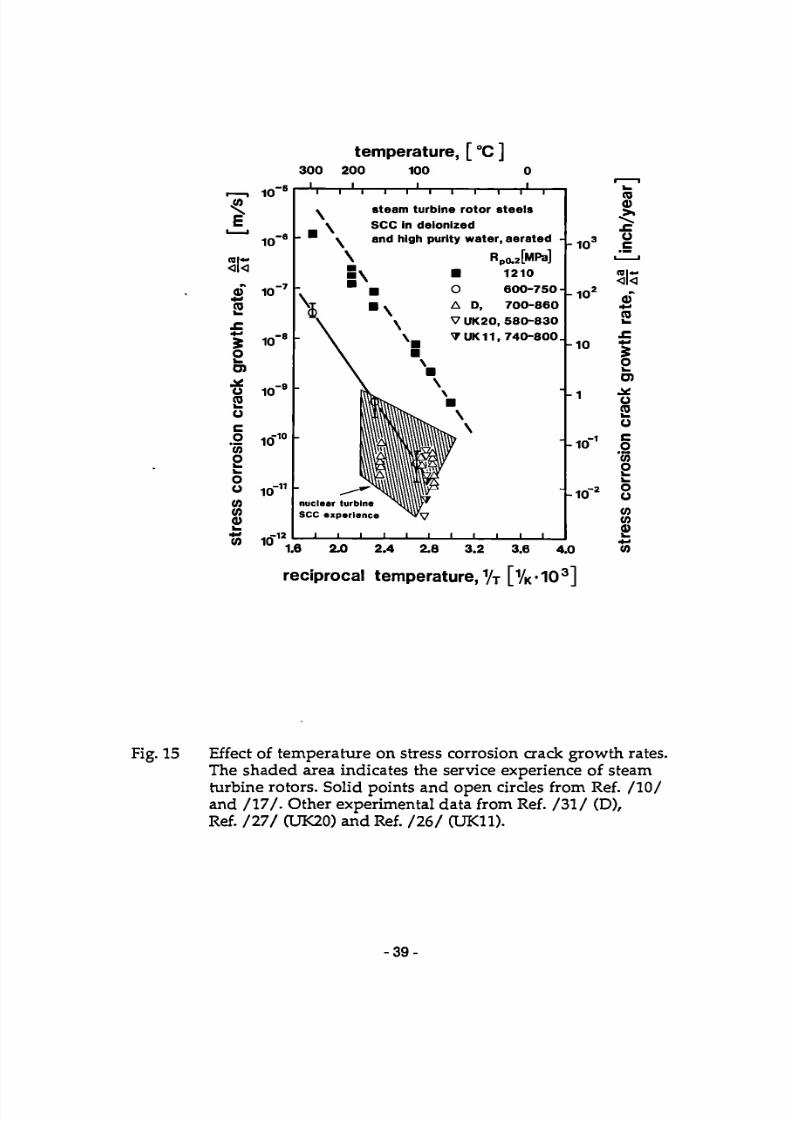
7/27/2019 SCC Evlauation by OEMS
http://slidepdf.com/reader/full/scc-evlauation-by-oems 49/84
I
o o co
(O ©
temperature, [ °C ]
30 0 200 100 o
1 0
10
ral-<l<
©"
.©
S 2 O ) .S É o ni
10
10
10
I io"1
C O
o
10
W 10
r-V
\ . ■
' \
-
-
I
\ \ \ S
■
nuc lear turb
S C C
■
experle
1
i i i i 1 1 1 1 1
steam turbine rotor steels
SCC in deionized
and high purity water, aerated -
■
\
l \ \ \ \m\\ \ \ \
ne ^<S
nee
1 '
R
■ O
A D, VUK2 0
\ B TUK1 1
■ \ ■ \ \ ■ tow \
«■AW X
I 1 I 1
poJMPa] 1210
6 0 0 - 7 5 0 -7 0 0 - 8 6 0
5 8 0 - 8 3 0
7 4 0 - 8 0 0 .
-
-
i i
- 1 0 °
1 0 '
10
- 1 0
1 0 '
1.6 2.0 2 .4 2.8 3.2 3.6 4.0
reciprocal temperature, 1/T [1/K'10
3]
(0
ral—
<k ©
!"
5 O
O) ü R J
C o '55 S o u to
(0 ©
Fig. 15 Effect of temperature on stress corrosion crack growth rates. The shaded area indicates the service experience of steam turbine rotors. Solid points and open circles from Ref. / I O / and / 1 7 / . Other experimental data from Ref. / 3 1 / (D), Ref. / 2 7 / (UK20) and Ref. / 2 6 / (UK11).
-39-

7/27/2019 SCC Evlauation by OEMS
http://slidepdf.com/reader/full/scc-evlauation-by-oems 50/84
«I \ , E, col«-
« ni
S o
¿c o CO
CO
o w w o o c o c o CD
10
S 10
SC C steam turbine rotor steels
■ H 2 ° . 1 ° 0 O C { deionized
• H 20 , 160 °C I
0.001 0.01 0.1 1 10 100 1000
oxygen concentration [ 0 2 1 , ppm
Fig. 16 Effect of dissolved oxygen on stress corrosion crack growth rates in steam turbine rotor steels exposed to water, Ref. / 1 7 / .
Additional data (open squares) from Ref. / 3 1 / . The partly intergranular SCC observed in CERT tests in water with 200 ppb O2 and 1 ppm CO2. Ref. /25/ ,f a l s also in the 160°C scatterband shown here (9 x 10~10 m/ s ) .
-40-

7/27/2019 SCC Evlauation by OEMS
http://slidepdf.com/reader/full/scc-evlauation-by-oems 51/84
IA
E
I « 10
« T 4- »
ra
S
o
¿t o C O
e o "5 o
o o 0)
o
. -8 S C C steam turbine rotor steels
■ H 20 , 100 °C
• H 20 , 160 °C
H , 0 , 1 0 0 ° C | . . . M ' deiomzed
10 12
0.001 0.01 0.1 1 10 100 1000
carbon dioxide concentration [ C 0 2 ] , ppm
Fig. 17 Effect of carbon dioxide concentration on stress corrosion crack growth rates in steam turbine rotor steels exposed to hot water, Ref. / IO, 17 / . The partly intergranular SCC crack growth rates observed by CERT in water with 200 ppb O2 and 1 ppm CO2,
Ref. / 2 5 / , fall also in th e 160°C scatterband shown here. The crack growth rate data measured in COST Program 15, Ref. / 2 3 / , fall also in th e 100°C scatterband shown here (3 x 10" 11 m/ s ) .
■41

7/27/2019 SCC Evlauation by OEMS
http://slidepdf.com/reader/full/scc-evlauation-by-oems 52/84
E
10
10 (Dl«' <l<
S io~
o>
1 i o1 0
c O - i i w io o 1_
o Ü -1 2
10 If ) (A
d) > _ 0) 1 0 - 1 3
1 1 1 1 1 1 1 1 1 1 1
steam turbine rotor steels
commercial steels, clean steels, specially
alloyed steels , S C C , deionized H 2O,100°C
■ [ 0 2 ] * 0 . 01 p p m . no C 0 2
• [ 0 2 ] = 0.1 p p m , [ C 0 2 ] - 100 ppm
A [ 0 2 ] = 8 p p m , [ C 0 2 ] - 0 .7ppm "
V ' - Í ' A —
^ i* g * á
(A =D , 1 0 0 ° C ) (V = UK 2 0 , 9 5 ° C )
_i i i i l i i
100 2 0 0 2 4 0
s t ress i n t ens i t y , Kz, [MNm"3 /2
]
Fig. 18 Effect of stress intensity, oxygen, and carbon dioxide on stress corrosion crack growth rates in steam turbine rotor steels in water near 100°C. Main data base from Ref. / I O / and / 1 7 / , bu t data from Ref. / 2 3 / , / 2 7 / , / 3 1 / agree very well with it.
- 4 2 -
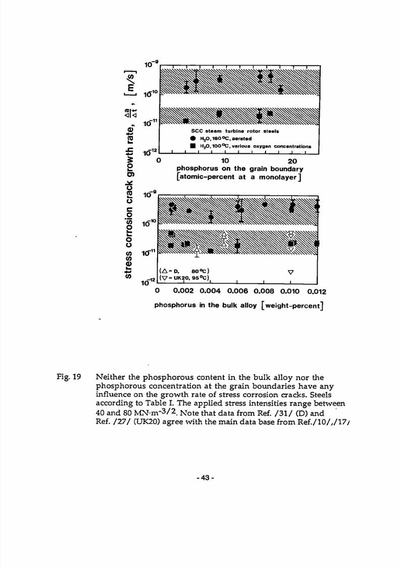
7/27/2019 SCC Evlauation by OEMS
http://slidepdf.com/reader/full/scc-evlauation-by-oems 53/84
10"
( O l * *
<l<
0) ţa
O)
(0
1 0 '
S 10 5 o
SC C steam turbine rotor steels
• H20,160 »C , aerated
■ HjO. IOO 1^ , various oxygen concentrations
_ ] _ _ 1 _ -1 _
0 10 20
phosphorus on the grain boundary
[atomic-percent at a monolayer ]
10 '
( A = D , 80°C ) (V=UK20 , 95°C)
0 0 .002 0 .004 0 .006 0 .008 0.010 0.012
phosphorus in the bulk alloy [we ight -percent ]
Fig. 19 Neither th e phosphorous content in th e bulk alloy nor the phosphorous concentration at the grain boundaries have any influence on the growth rate of stress corrosion cracks. Steels according to Table I. The applied stress intensities range between 40 and 80 MN-m-3/2 . Note that data from Ref. / 3 1 / (D) and Ref. / 2 7 / (UK20) agree with the main data base from Ref./10/,/17y
- 4 3 -

7/27/2019 SCC Evlauation by OEMS
http://slidepdf.com/reader/full/scc-evlauation-by-oems 54/84
0>
(O l i
!"
S O O) .2 Ü (0
o 'iõ
s 1 -o o CO
CO
0)
T
S C C . steam turbine rotor steels
1 0 * r- • H 2 0 , 1 6 0 ° C
■ H 2 0 , 1 0 0 ° C
various oxygen
contents
10
( A = D, 80 "C ) (V = UK20, 95 °C ) i ' I I
0.00 0.20 a 4 0 0.60 0 .80 1.00 1.20
manganese in the bulk alloy,[weight percent]
Fig. 20 The manganese content of the steels has no influence on their stress corrosion crack growth rate. Steels according to Table I. The applied stress intensities range between 40 and 80 MN -m ' 3 / 2 . Note that data from Ref. / 3 1 / (D) and Ref. / 2 7 / (UK20) agree with the main data base from Re f . / 10 / , / 1 7 / .
- 4 4 -

7/27/2019 SCC Evlauation by OEMS
http://slidepdf.com/reader/full/scc-evlauation-by-oems 55/84
c o
»cg
$O
O)
oCO
C
o'35owwOO
(flC O0)
10
£ 10
— I 1 1 1 1 1 1 1 1 1 —SCC steam turbine rotor steels
H,0, 16 0 °C ) . .2
„ various oxygen contentsH 20, 10 0 °C )
( A = D , 1 0 0 ° C )(V = UK 20 , 95 °C)
_ J I I I 1 L J L
0.0 0 0.04 0.08 0.12 0.16 0.20 0.24
silicon in the bulk alloy, [weight percent]
Fig. 21 The silicon con tent of the steels has no influence on their stresscorrosion crack growth rate. Steels according to Table I. Theapplied stress intensities range between 40 and 80 MN-m'3/2, Notethat data from Ref. / 3 1 / (D) and Ref. / 2 7 / (UK20) agree with themain data base f rom R ef . /10 / , /1 7/ .
-45 -

7/27/2019 SCC Evlauation by OEMS
http://slidepdf.com/reader/full/scc-evlauation-by-oems 56/84
(O
I IO"
(0
SoO)
oni
co»o
ouV)ID0 >
io"8
h
-\—i—i—i—i—i—i—i—r
steam turbine rotor steels
SCC in 160°C water ,
various oxygen contents
(A=D, 150°C)
J I I l_
0.00 0.20 0.40 0.60 0.80 1.00
molybdenum in the bulk alloy, [weight-%]
Fig. 22 The molybdenum content of the steel has noinfluence on their stress corrosion crackgrowth rate. Steels according to Table I. Theapplied stress intensities range between 40and 80 MN-m " 3/ 2. Data from Ref./IO,17/. Notethe somewhat lower data from Ref./31/ (D ), duepartly to lower temperature.
-46-

7/27/2019 SCC Evlauation by OEMS
http://slidepdf.com/reader/full/scc-evlauation-by-oems 57/84
UTJ 10 a l -
(0
S o
o
o (0
o o ca co a>
- 7
10
10
I W - h
10
i 1 1 1 1 r ~
steam turbine rotor steels
S C C in 160 °C wate r ,
various oxygen contents
(A= D.iso'te) A J I L ÏÏ 0.0 1.0 2.0 3.0 4 .0
nickel in the bulk alloy [we igh t -%]
Fig. 23 The nickel content of th e steels has no influence on their stress
corrosion crack growth rate. Steels according to Table I. The applied stress intensities range between 40 and 80 MN-m"3/2 . Note th e somewhat lower data from Ref. / 3 1 / (D), due partly to lower t empera ture .
■47-

7/27/2019 SCC Evlauation by OEMS
http://slidepdf.com/reader/full/scc-evlauation-by-oems 58/84
(O
o l l
¿ (O
5 o O)
o
co o
o o
10 -8
Ï 10 -1 2
"~I 1 1 1 1 1 1 1 1 1 1
SCC steam turbine rotor steels
A H O 1 6 0 °C ) 2 ' {various oxygen contents
■ H 20 , 100 °C I
(A = D, 100 °C ) ( V = U K 2 0 , 9 5 ° C )
I I I I I L J L
0 . 000 0 .002 0 .004 0.006 0.008 0.010 0 .012
sulfur in the bulk alloy, [weight percent]
Fig. 24 The sulfur content of the steels has no influence on their stress corrosion crack growth rate. Steels according to Table I. The
applied stress intensities range between 40 and 80 MN-m ' 3 / 2 . Note that data from Ref. / 3 1 / (D) and Ref. / 2 7 / (UK20) agree with th e main data base from Re f . / 10 / , / 1 7 / .
- 48 -

7/27/2019 SCC Evlauation by OEMS
http://slidepdf.com/reader/full/scc-evlauation-by-oems 59/84
' c o '
c o l * * <l<
Ï O k . O) JÉ ü
<0
C
o '5 o
O
o (0 05 0)
10
•3 10
10
1 1 1 1
SCC steam turbine rotor steels
• H 20 , 160°C
■ H 20 , 1 0 0%
$ steam, 9 0 % ,
various oxygen contents
data from GEC/CEGB
50 100 150 200 250 3 00
fracture toughness, K | C, [ M N I T T3'
2]
Fig. 25 At comparable strength levels, there is no effect of fracture toughness on the growth rates of stress corrosion cracks. Fracture toughness values taken at room temperature solid points from Ref. /IO,17/. GEC/CEGB data from Ref./2/. Steels according to Table I. The applied stress intensities range bet-ween 40 and 80 MN-nr 3/2.
-49-

7/27/2019 SCC Evlauation by OEMS
http://slidepdf.com/reader/full/scc-evlauation-by-oems 60/84
,—, (0
r o l * -
<l<
b
JZ 4 - *
5 o
^ ) J¿
o
ü c o W o w o o 0)
(0 0) ^ ■> (0
1U
io "7
10" 8
- 9 10
io 1 0
-1 1 10
-1 2 10
l ñ 1 3
" I
I
I
I
i
steam turbine rotor steel 3.5NiCrMoV
SCC i nH jO , 160 «C
• A
■
—
-
-
K,c as received
as received -t- step cooled A
as received + 4 5 0 ° / 10 h
•
r *•* A* . / i f T i l
i i i i
.[MNifi3*2]
2 00
197
110
—
■_ T
—
"~
i
0 20 4 0 6 0 80 100 120
stress intensity, K_, [MNm"3/2]
Fig. 26 The stress corrosion crack growth rates in th e plateau range appear to be independent of the degree of temper embrit t lement. Steel number 9 in Table I. The fracture toughness values are taken at room temperature . Pe f . / 1 0 , 1 7 / .
■50-

7/27/2019 SCC Evlauation by OEMS
http://slidepdf.com/reader/full/scc-evlauation-by-oems 61/84
10
■co
£ io' ( O l * -
<l< S 10
5 O h . O)
ü «J
C o 'iõ o w o o (O w
a>
10
10
10
10
10 ía
i / stress corrosion cracking
k 3.5NiCrMoV rotor steel
H 20 , Jp0 ° C , aerated
▲ CH 4
• CH 4
■ CH 4
D D
B o
B UK20
"C
10 0
100
10 0
10 0
80
95
RpO 2 [MN/nr t ]
1420
1240
7 56
857
1200
830
J_
2 0 4 0 6 0 8 0 100 120
[ - 3 / 2 I MNm J
Fig. 27 Effect of stress intensity and yield strength on the growth rates of stress corrosion cracks in steam turbine rotor steel exposed to water near 100°C. Note that data from four different sources coincide closely: Ref. / 1 7 / (CH4), Ref. / 3 1 / (D), Ref. / 2 7 / (UK20) and Ref. / 2 3 / 05 ,3 x 10"11 m / s , 100°C, R po.2 = 670 MPa).
-51
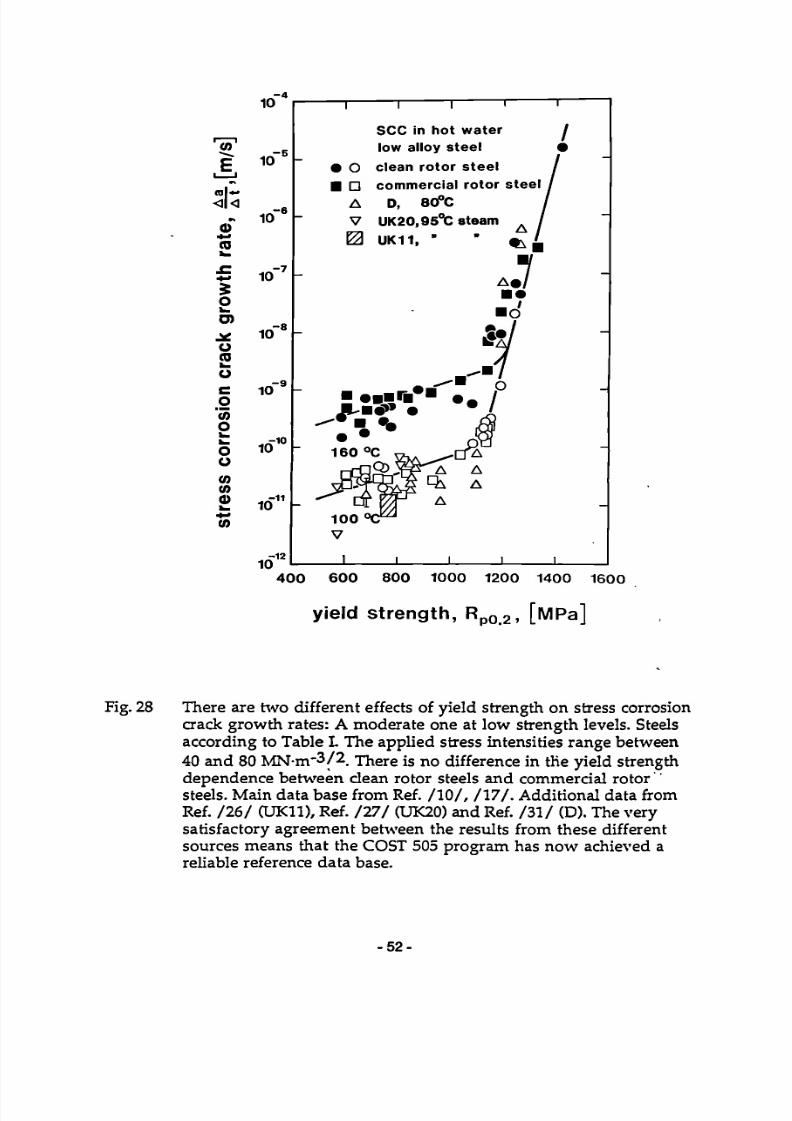
7/27/2019 SCC Evlauation by OEMS
http://slidepdf.com/reader/full/scc-evlauation-by-oems 62/84
(O
E ■ i ni»* <l<
< B
4- * C O
10
10
10
5= 10
o O)
o co
o c
o
"55
o
o ü
(0 (0 < J >
(0
10
10
10
io"11
10
T T
SCC in ho t wa t e r
low al loy s tee l
• O c lean r o t o r s t e e l ■ D commerc i a l r o t o r s t ee l
A D, 80°C
V UK20,95°C steam
0 UK11 , "
■ • ■ ■ ! ■ * ■ mm I
400 600 800 1000 1200 1400 1600
yield s t r e ng t h , Rp0 2 , [ MP a ]
Fig. 28 There are tw o different effects of yield strength on stress corrosion crack growth rates: A moderate one at low strength levels. Steels according to Table I The applied stress intensities range between 40 and 80 MN-m " 3A There is no difference in the yield strength dependence be tween clean rotor steels and commercial rotor steels. Main data base from Ref. / I O / , / 1 7 / . Additional data from Ref. / 2 6 / (UK11), Ref. / 2 7 / (UK20) and Ref. / 3 1 / (D). The very satisfactory agreement between th e results from these different sources means that the COST 505 program has now achieved a
reliable reference data base.
• 5 2 -

7/27/2019 SCC Evlauation by OEMS
http://slidepdf.com/reader/full/scc-evlauation-by-oems 63/84
1.0
0.9
0.8
0.7
0.6
0.5
0.4
0.3
0.2
0.1
0.0
■==■ ratio of stess intensity at branch crack K j
to stress intensity at single crack
O Maraging Steel □ PMMA tempered
• Low Alloy steel
i
1 2 3 4 5
total number of branch cracks, n
Fig. 29 The stress intensity at branch cracks decreases as th e number n of branch cracks increases. This can be experimentally verified by measur ing the fracture toughness in materials with branched precracks. Ref. / 3 3 / .
■ 53 -

7/27/2019 SCC Evlauation by OEMS
http://slidepdf.com/reader/full/scc-evlauation-by-oems 64/84
cr i t ica l d e p t h s of single a n d b r a n c h e d c r a c k s
LLLi-
VTTJ° single c r a c k : K = CT Va7
#Y
crack w i t h
n branches ith | k = K/Vn hes J k = o V a s /r i • Y
3cn = n 3cs
Fig. 30 Since the stress intensity at branched cracks is smaller, the critical depth of such cracks is larger, Ref. / 3 4 / . This means longer residual lifetimes of cracked components.
■ 5 4 -

7/27/2019 SCC Evlauation by OEMS
http://slidepdf.com/reader/full/scc-evlauation-by-oems 65/84
1.0
'If en (0
j t Je " s s s 5 u
*1 a g c i. 3 O
I 5
0.4
0 . 2 -
? 3 •5 E sí JÉ o
10.2 A
0.11 V-
- A 4.0 SCC-length Ja
Y 0.65
-T 0.38
2.40 V
4 1 5 . 8
O Left side • Right side
Number of crack tips
Influence of Number of SCC-Crack Tips on Stress Intensity Factor
Fig. 31 The stress intensity at branch cracks is smaller than at single
cracks. Observations on specimens from steam turbine rotors containing actualstress corrosion crack systems, Ref. /20/.
■ 5 5 -
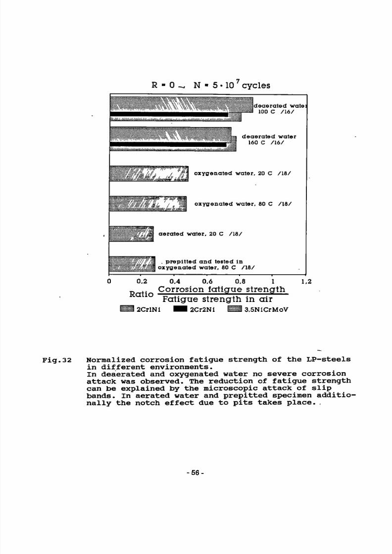
7/27/2019 SCC Evlauation by OEMS
http://slidepdf.com/reader/full/scc-evlauation-by-oems 66/84
R = 0 ^ N ■ 5 • 10 cycles
w deaerateci wate: 100 C 716/
, i deaerateci water ' 160 C / 1 6 /
fffifm^W'''^!^
WUUKÊÁ oxygena ted water, 20 C 718/
oxygena ted water, 80 C / 1 8 /
aerated water, 20 C 718/
. prepitted and tested In oxygena ted water, 80 C 7187
0.2 0,4 0,0 0,8 1 1,2 Corrosion fa t igue s t rength Fat igue s t rength in a ir
■ 2CrlNl M 2Cr2Nl H I 3.5NlCrMoV
Fig.32 Normalized corrosion fatigue strength of the LP-steels in different environments. In deaerated and oxygenated water no severe corrosion attack was observed. The reduction of fatigue strength can be explained by the microscopic attack of slip bands. In aerated water and prepitted specimen additio-nally the notch effect due to pits takes place. .
-56-

7/27/2019 SCC Evlauation by OEMS
http://slidepdf.com/reader/full/scc-evlauation-by-oems 67/84
R ' O , N ■ 5 • 10 cycles
/ l ó /
/ l ó /
/ 1 6 /
/ 3 ó /
/ 3 ó /
0.2 0.4 0.6 0.8 1 1,2 Fat igue s t rength p r e co r r od ed
Ratio Fat igue s t rength " t
Fig.33 Pure notch effect of precorroded specimens (tested in air after precorrosion) Homogeneous attack causes moderate fatigue strength de-crease. Strong reduction can appear after local corro-sion depending on the size and the geometry of the sur-face defects.
-57-

7/27/2019 SCC Evlauation by OEMS
http://slidepdf.com/reader/full/scc-evlauation-by-oems 68/84
O) c 0 )
(A C
(A (O 0) i _ * • > (O
O )
c (Q
C l _
a >
(O
1.0
0.8 -
<» 0.6
0.4
0.2 mean stress
tensile strength
■ V 0.8
corrosion fatigue with mean stress
Fig. 34 Schematic representation of the effect of mean stress and environments on the fatigue strength of steam turbine rotor and blade steels. Note that pitting corrosion should be avoided if acceptable fatigue strength is desired.
- 5 8 -

7/27/2019 SCC Evlauation by OEMS
http://slidepdf.com/reader/full/scc-evlauation-by-oems 69/84
o.S
600
400
200 -
-200
-400
mean stress (MPa) mean stress (MPa)
Fig.35 Comparison of the corrosion fatigue behaviour of a conventional 12% Cr-steel and the duplex steel developedin COST 505.
-59-
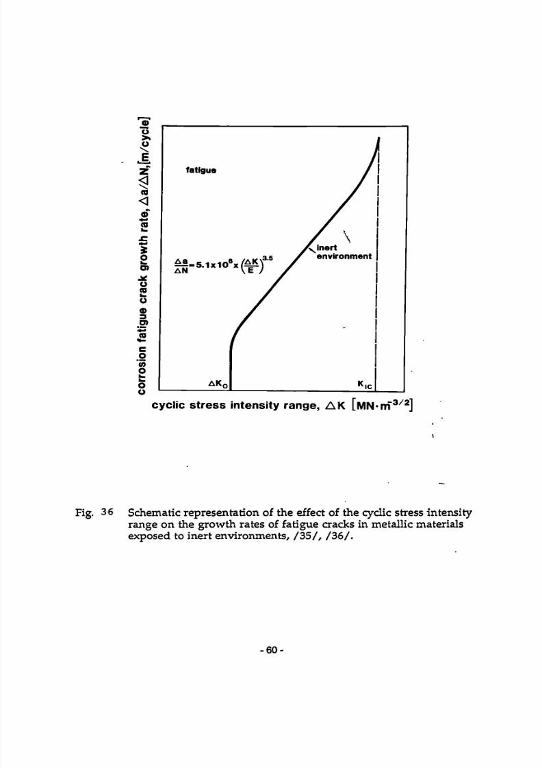
7/27/2019 SCC Evlauation by OEMS
http://slidepdf.com/reader/full/scc-evlauation-by-oems 70/84
cyclic stress intensity range, A K [MN-m"3/2]
Fig. 36 Schematic representation of the effect of the cyclic stress intensity range on the growth rates of fatigue cracks in metallic materials exposed to inert environments, / 3 5 / , / 3 6 / .
■ 60 -

7/27/2019 SCC Evlauation by OEMS
http://slidepdf.com/reader/full/scc-evlauation-by-oems 71/84
0)"õ>>ü\J=
z
<
(D
5oO)
o(0
od)3O)
co'55oh .
oo
true corrosion fatigue
environment
AK f
cycl ic s t ress in tensity range, A K [w iN-n f3 7 2
]
Fig. '37 In "true" corrosion fatigue there is a de ar but limitedacceleration of the growth rate of fatigue cracks comparedto inert environments, / 3 6 /.
-61

7/27/2019 SCC Evlauation by OEMS
http://slidepdf.com/reader/full/scc-evlauation-by-oems 72/84
O >• O \
r
o < < D (0
o O)
O (0
3 O)
c
o '55 o
stress corrosion
under cyclic loads
i
AK 0
/
r
r
)
decreasing i frequency /
Á^ Inert / environment
K|C
cyclic stress intensity range, A K [MN 'm 3 / 2 ]
Fig 38 If stress corrosion is possible at th e same time as fatigue, crack growth rates pe r load cycle can become very high and they are also strongly frequency dependent , / 3 6 / .
■ 6 2 -

7/27/2019 SCC Evlauation by OEMS
http://slidepdf.com/reader/full/scc-evlauation-by-oems 73/84
ü > » o
CB
o <** re
O &■
D) ¿C
O (D i . O
O 3 O) * ■ •
re
10 3.5NiCrMoV
'S 1 0 " ° -
a i r , R=0.1 a i r , R)0.7 wa t e r , 100°C, R=0.1 wa t e r , 100°C, R)0.7
10 - 7
10 - 8
10"
10
£ 10
-10
- n
effect oí t h e
e n v i r o n m e n t /
I I U l l I I
effect of t h e R - r a t i o
j i i i ' i i
1 2 4 10 20 40 100
cyclic stress Intensity range AK (MPa /m)
F ig . 39 Fa t i gu e and c o r r o s i o n f a t i g u e c rack growth r a t e s ob s e r -ved i n t h e 3.5NiCrMoV steam t u r b i n e r o t o r s t e e l s , based on r e f e r e n c e s / 1 6 , 3 7 / . The cu rve s of o t h e r LP s t e e l s a r e ve ry s i m i l a r .
• 6 3 -
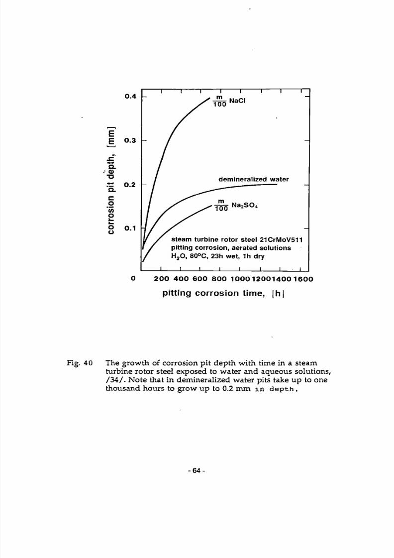
7/27/2019 SCC Evlauation by OEMS
http://slidepdf.com/reader/full/scc-evlauation-by-oems 74/84
demineralized water
steam turbine rotor steel 21CrMoV511
pitting corrosion, aerated solutions
H 2 0, 80°C, 23h wet, 1h dry
_L _ l _ _L _ l _ _L
2 0 0 4 0 0 6 0 0 8 0 0 1 0 0 0 1 2 0 0 1 4 0 0 1 6 0 0
pi t t ing corrosion t ime, |h|
Fig. 40 The gro wth of corrosion pit de pth with time in a steamturbine rotor steel exposed to water and aqueous solutions,/ 3 4 / . Note that in demineralized water pits take up to onethousand hours to grow up to 0.2 mm in d e p t h .
- 6 4 -
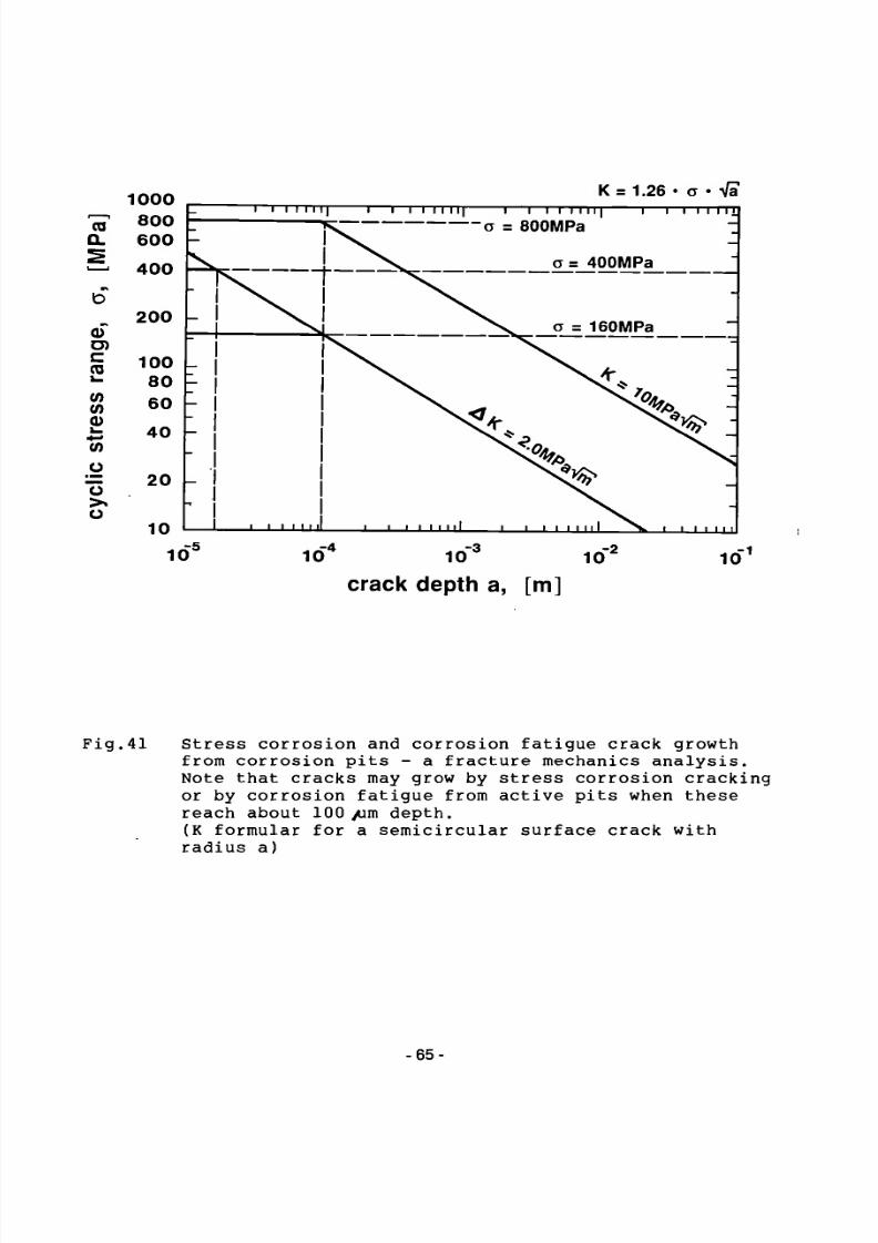
7/27/2019 SCC Evlauation by OEMS
http://slidepdf.com/reader/full/scc-evlauation-by-oems 75/84
1000Ta 800
a 600
— 400
b200
o>
a loo•- 80S 60a>
i: 40(A
o= 20 1->.o
10
10"J
K = 1.26 • a • Vi"I 1 I I 11 II 1 1 1 1 11 I I I 1 1 1 I I 1 I I I 1 1 1 1 1 111
V
Lts
1 1 1 1 1 L U
f ^ a = eOOMPa
v o = 400MPa
N . a = 160MPa
1 1 1 I I I I I I 1 1 L 1 1 1 I I I > W 1
-310 1 0" 10'
crack d epth a, [m]
10
Fig.41 Stress corrosion and corrosion fatigue crack growth
from corrosion pits - a fracture mechanics analysis.Note that cracks may grow by stress corrosion crackingor by corrosion fatigue from active pits when thesereach about 100 yum depth.
(K formular for a semicircular surface crack withradius a)
-65-

7/27/2019 SCC Evlauation by OEMS
http://slidepdf.com/reader/full/scc-evlauation-by-oems 76/84

7/27/2019 SCC Evlauation by OEMS
http://slidepdf.com/reader/full/scc-evlauation-by-oems 77/84

7/27/2019 SCC Evlauation by OEMS
http://slidepdf.com/reader/full/scc-evlauation-by-oems 78/84
7/27/2019 SCC Evlauation by OEMS
http://slidepdf.com/reader/full/scc-evlauation-by-oems 79/84
European Communities — Commission
EUR 13186 — Stress corrosion cracking and corrosion fatigue of steam-turbinerotor and blade materials
Edited by: J. B. Marriott
Luxembourg: Office for Official Publications of the European Communities
1991 - V, 65 pp., num. tab., fig. - 16.2 x 22.9 cm
Physical sciences series
ISBN 92-826-2017-4
Catalogue number: CD-NA-13186-EN-C
Price (excluding VAT) in Luxembourg: ECU 6.25
Modern steam turbines must retain a very high reliability throughout their service lifeof typically 200000 hours. Among the reasons for failure w hich have been observedin steam turbines during the last 20 years, stress corrosion cracking and corrosion fa tigue have been prominent. Thus, attention has been d rawn to the stress corrosionresistance and corrosion fatigue of steam-turbine rotor and blade materials.
The present paper summarizes and evaluates the present state of the art, mainly
based on the results of the international cooperative research programme COST 505,recent literature and the authors' ow n experience.
An attempt is made to describe in quantitative terms the major influential parameterson stress corrosion and corrosion fatigue behaviour of steam-turbine rotor and bladematerials in service-related environments.
Five topics are given special attention:(i) stress corrosion crack initiation,(ii) stress corrosion crack propagation,
(iii) corrosion fatigue crack initiation,(iv) corrosion fatigue crack propagation,(v) pitting corrosion.
It is shown that fracture mechanics can be used to understand the transition fromcrack initiation to crack grow th.

7/27/2019 SCC Evlauation by OEMS
http://slidepdf.com/reader/full/scc-evlauation-by-oems 80/84

7/27/2019 SCC Evlauation by OEMS
http://slidepdf.com/reader/full/scc-evlauation-by-oems 81/84

7/27/2019 SCC Evlauation by OEMS
http://slidepdf.com/reader/full/scc-evlauation-by-oems 82/84
7/27/2019 SCC Evlauation by OEMS
http://slidepdf.com/reader/full/scc-evlauation-by-oems 83/84
Venta y suscripciones • Salg og abonnement • Verkauf und Abonnement * ΠΩΛΉΣΕΙΣ ΚΑΙ συνδρομές
Sales and subscriptions • Vente et abonnements • Vendita e abbonamenti Verkoop en abonnementen • Venda e assinaturas
BELG I QUE / B E L G I Ë
Mon i t e u r b e l g e /
Be l g i s ch S t a a t s b l a d Rue de Louva in 42 / Leuvenseweg 42
1000 Bruxel les / 1 0 0 0 Brusse l Té l . ( 0 2 ) 5 1 2 00 26
Fa x 511 01 84
C C P / Post reken ing 0 0 0 - 2 0 0 5 6 0 2 - 2 7
Aut res distr ibuteurs /
Over ige verkooppunten
L ibra i r i e e u r o p é e n n e / Eu r o p e a « Bo e k h a n d e l
Avenue Alber t Jonnar t 50 /
Albar t Jon nart aa n 50
1 2 0 0 Bruxel les / 1 2 0 0 Brusse l Té l . (02) 7 34 0 2 8 1
Fa x 7 35 0 8 60
J e a n De L a n n o y
Avenue du Roi 202 /KoningslAAn 202
1060 Bruxe l l e s / 1060 Brussel Té l . (02) 5 3 8 51 69
Té lex 6 3 2 2 0 U N BOOK B
C R E D O C
Rue de la Mon t agne 34 / Berg at raa t 34
B te 11 / Bu s 11
1 0 0 0 Bruxel les / 1000 Brussel
J . H. S c h u l t z I n f o rma t i on A/ S
EF -Pub l i k a t i one r
Ott i l iavej 18
2 5 0 0 Va lby
TH . 3 6 44 2 2 66
Fax 3 6 4 4 01 41
Girokonto 8 00 06 86
BR D E U T S C H L A N D
Bun d e s a n z s i g e r V e r l a g
Breite S t r a S e
Post fach 10 80 06
5 0 0 0 Köln 1
Tel.(02 21 )20 29-0 Fernschre iber
ANZE I GER BONN 8 882 595
Fa x 20 29 27 8
GR E E C E
G . C . E l e f t h e r oudak i s SA
Internat ional Bookstore Nikis S t ree t 4 1 0 5 6 3 Athens Te l . ( 0 1 ) 3 2 2 63 23
Te lex 2 1 9 4 1 0 ELEF Fa x 3 2 3 9 8 2 1
E S PAÑA
Bo l e t i n Of i c i a l de l E s t a d o
Trafalgar , 27
2 8 0 1 0 Mad r i d
Te l . ( 91 ) 4 4 6 6 0 0 0
Mund i - P r e n s a L i b r o s , S.A. Caste l ló , 37
2 8 0 0 1 Mad r i d
Te l . (91) 431 33 99 (Libros) 43 1 32 22 (Suscr ipc iones ) 43 5 36 37 (Dirección)
Té lex 4 9 3 7 0 - M P U - E
Fax (91) 5 7 5 3 9 9 8
Sucursa l :
L i b r e r i a I n t e r n ac i ona l A E D O S
C o r s e j o de C i en t o , 39 1
0 8 0 0 9 Barce lona
Te l . ( 9 3 ) 3 0 1 6 6 15 Fax (93) 3 1 7 01 41
Genera l i t ä t de Ca t a l unya :
L l i b r e r i a Rambla dela estudis
Ramb l a , 118 (Pa lau Mo j a )
0 8 0 0 2 Barce lona Te l . (93) 3 0 2 66 3 5
3 0 2 64 6 2
F R A N C E
J o u r n a l of f i c ie l S e r v i c e de a pub l i c a t i ons
d a s C o mm u n a u t é s européennes
2 6 , rue Desaix
7 5 7 2 7 Paris C e d e x 1S
Té l . ( 1 ) 4 0 58 7 5 0 0
Fa x ( 1 ) 4 0 5 8 7 5 7 4
P O R T UGA L Ö S T E R R E I C H
I RELAND
ITALIA
L i c o s a Spa
Vi a Benede t t o Fort ini , 1 2 0 / 1 0
Case l l a posta le 552
5 0 1 2 5 Firenze Te l . ( 055 ) 64 54 1 5
Fa x 6 4 12 5 7
Te lex 5 7 0 4 6 6 L I C O S A I
C C P 3 4 3 5 0 9
Subagen t i : L ibre r ia sc i en t i f i c a
Luc i o de Bias io - A E I O U
Vi a Merav ig l i . 16
2 0 1 2 3 Mi lano
Te l . (02) 8 0 7 6 7 9
He r d e r Ed i t r i c e e L ibre r ia
Piazza Montec i to r io , 1 1 7 - 1 2 0
0 0 1 8 6 R om a
Tei. (06) 67 9 46 287679 5 3 04
L ibre r ia g i u r i d i c a
V ia XII Ot tobre , 172/R
16121 Genova
T e l . ( 0 1 0 ) 5 9 56 93
GRAN D - D U C H É DE L U X EMBOURG
Abonnemen t s seu lement Subscr ip t ions only
Nu r für Abonnemen t s
Me s s a g e r i e « P a u l K r a u «
1 1 , rue Chr is tophe Plantin
2 3 3 9 Luxembou rg
Té l . 4 9 9 88 8 8
Té lex 2515
C C P 4 9 2 4 2 - 6 3
NEDERLAND
S D U U i t g eve r i j
Christoffel Planti jnstraat 2 Postbus 2 0 0 1 4
2 5 0 0 EA ' s -G r a venhage
Te l . ( 070 ) 37 6 98 60 (bestel l ingen)
Fa x ( 070 ) 3 4 7 6 3 51 Te lex 3 2 4 8 6 s tdru nl
I m p r e n s a Na c i o n a l
C a s a da Moe d a , EP Rua D. Franc isco Manue l de Me lo , 5 P-1092 L isboa C o d e x
Tel. (01)69 34 14
D i s t r i bu i do r a de L iv ros
Be r t r a n d , Ld."
G r u p o Be r t r a n d , SA
Rua das Ter ras dos Va les , 4-A
Apa r t ado 37
P-2700 Amad o r a C o d e x
Te l . (01) 4 9 3 9 0 5 0 - 4 9 4 8 7 8 8
Te lex 1 5 7 9 8 BERD I S
Fax 4 91 0 2 55
G o v e r n m e n t Pub l i c a t i ons
S a l e s Of f i c e
S un All iance Hou s e
Moleswor th S t r e e t Dublin 2
Te l . 71 0 3 0 9
or by post
G o v e r n m e n t S t a t i o n e r y Of f i c e
E E C S e c t i o n
6 th f loor Bishop S t r e e t Dublin 8
Te l . 7 8 1 6 66
Fa x 7 8 0 6 4 5
UN I T ED K I N G DOM
H M S O B o o k s (PC 16 )
H M S O Publicat ions Cen t r e 51 Nine Elms Lane
London SW8 5DR
Te l . (071) 873 9 0 9 0
Fa x GP3 873 8 4 6 3
Te lex 29 7 1 138
Sub - agen t :
A l a n A r m s t r o n g Ltd
2 Arkwr igh t Ro a d
Read ing , Berks RG2 0SQ
T e l . ( 0 7 3 4 ) 7 5 1 8 55
Te lex 8 4 9 9 3 7 AAALTD G
Fax ( 0 73 4 ) 75 51 64
C A N A D A
Re n o u f Pub l i s h i ng Co . Lt d
Ma i l orders — He a d Of f ice : 1294 A l g oma Ro a d
O t t aw a , Ontario K1B 3W8
Te l . ( 613 ) 741 4 3 3 3
Fax ( 613 ) 741 54 3 9
Te lex 0 5 3 4 7 8 3
Ot t awa S t o r e : 6 1 Spa r k a S t r e e t Te l . ( 613 ) 2 3 8 89 85
To ron t o S t o r e : 2 1 1 Yo n g e S t r e e t Te l . ( 416 ) 3 6 3 31 71
JAPAN
K inokun i y a C o m p a n y Lt d
1 7 - 7 Sh in juku 3-Chome Sh in juku-ku
Tokyo 160 - 9 1
Te l . ( 03 ) 3 5 4 01 31
J o u r n a l D e p a r t m e n t
PO Box 55 Ch i t o se
Tokyo 156
T e l (03) 4 3 9 01 24
MAG Y A ROR S Z AG
Kozpont :
Budapes t I., Att i la út 93 . H-1012
Levé lc im:
Budapes t . Pf.: 15 H-1253
Tel. 3 6 ( 1 ) 5 6 8 2 1 1 Te lex (22) 4 7 1 7 AG I N F H-61
M a n z ' s c h e V e r l e g s -
u n d Univers i tä tsbuchhand lung Kohlmark t 16
1014 Wien
Te l . ( 0 2 2 2 ) 5 3 1 61-0
Te lex 11 25 00 BO X A
Fa x ( 0222 ) 531 61-61
S C H W E I Z / S U I S S E / SV I ZZERA
O S E C
S t amp f enbachs t r aße 65
8 0 3 5 Zür ich
Te l . ( 01 ) 3 65 51 51
Fa x ( 01 ) 3 6 5 54 11
S VER I GE
B T J
Bo x 2 0 0
2 2 1 0 0 Lund
Te l . ( 046 ) 18 00 0 0
Fa x ( 046 ) 1 8 01 25
TÜRK I Y E
D ü n y a S ü p e r D a g i t i m Ticaret
v e sanay i A.Ş. Nar i lbahçe S o k a k No. 15
Caga l og l u
Istanbul Te l . 5 1 2 01 90
Te lex 2 3 8 2 2 D S V O - T R
UN I T ED S TATE S OF AM E R I C A
U N I P U B
4611 -F Assemb l y Dr ive
L a n h am . MD 2 0 7 0 6 - 4 3 9 1
Te l . To l l Free (8O0) 274 4 6 8 8
Fa x ( 301 ) 459 0 0 5 6
Te lex 7 1 0 8 2 6 0 4 1 8
Y UGO S L A V I A
P r i v r edn i V j e sn i k
Bulevar Lenj ina 171 / X I V
1 1 0 7 0 - Beog r ad
Yougos lav ie
AUTRES PAYS OTHER COUNTRIES ANDERE LANDER
Office des publications officielles
des Communautés européennes
2, rue Merc ie r L-2985 Luxembou rg
Té l . 4 9 9 2 8 1
Te lex P U BO F LU 1324 b
Fa x 4 8 65 7 3 C C banca i re BIL « O 0 9 Æ 0 0 3 / 7 0 0

7/27/2019 SCC Evlauation by OEMS
http://slidepdf.com/reader/full/scc-evlauation-by-oems 84/84
NOTICE TO THE READER
All scientific and technical reports published by the Commission of the European
Communities are announced in the monthly periodical 'euro abstracts'. For sub
scription (1 year: ECU 84) please w rite to the address below . o
a
o>
mzI
o