scare your colleagues: parametric surface...
TRANSCRIPT

Scare Your Colleagues: Parametric Surface Modeling, Blocks, and Arrays with AutoCAD® 2012
AC4054-P In this advanced class, you will learn how to better use parametric features in AutoCAD for both drafting and modeling. We will start with parametric surface modeling, discuss the creation of parametric blocks, and show you how to use the new associative array with expressions. Empower your work with the parametric features in AutoCAD 2012.
Learning Objectives At the end of this class, you will be able to:
• Create smarter blocks using surface modeling and parameters
• Explain how the associative framework works in AutoCAD
• List the secrets for use of associative array in AutoCAD 2012
• Describe best practices for using parameters in surface modeling
About the Speaker Guillermo has worked for Autodesk since 2006, first as an application engineer based in Argentina, then as senior product manager for AutoCAD® in San Francisco, and now as senior product manager for Suites Technology Group. He has been responsible for free-form design, surface modeling, parametric and overall 3D enhancements in AutoCAD 2010 and 2011. He also worked in Autodesk® Materials and UI enhancements across applications. Prior to this, Guillermo was part of the reseller channel in Uruguay, as well as an architect and professor at two architecture schools. He has performed training and implemented multiple instances of AutoCAD, AutoCAD Architecture, Autodesk Inventor®, AutoCAD Revit® Architecture, Revit Structure, and Autodesk 3ds Max®. Guillermo spends his free time playing video games or rocking hard with his collection of bass guitars.

Scare Your Colleagues: Parametric Surface Modeling, Blocks, and Arrays with AutoCAD® 2012
2
Contents About the Speaker ...................................................................................................................... 1
1. The associative framework in AutoCAD ................................................................................. 3
Geometric and dimensional constraints ..................................................................................... 4
Parameters Manager .................................................................................................................. 8
Example ....................................................................................................................................... 9
2. Parametric Surfaces .............................................................................................................. 11
Using expressions in surfaces .................................................................................................. 11
Examples – parametric buildings .............................................................................................. 14
Best practices ............................................................................................................................ 15
Example ..................................................................................................................................... 17
3. Making 3D blocks with parametric surfaces ......................................................................... 21
Working in the block editor ........................................................................................................ 22
Adding data from Excel ............................................................................................................. 22
Example ..................................................................................................................................... 22
4. Associative array with AutoCAD 2012 .................................................................................. 28
Using associative arrays ........................................................................................................... 29
Using expressions in associative arrays ................................................................................... 33
5. Conclusions ........................................................................................................................... 35

Scare Your Colleagues: Parametric Surface Modeling, Blocks, and Arrays with AutoCAD® 2012
3
AutoCAD has had three releases in a row with incremental power around surface modeling and parametric design.
2011 will probably be remembered for the introduction of a very robust surface modeler, but there’s a feature within this workflow which should not be unnoticed.
As you may remember, AutoCAD 2010 introduced parametric drawing. This feature uses AutoCAD’s new associative framework in order to establish relationships and constraints in 2D linework..
And now AutoCAD 2012 introduces the Associative Array, with which we’ll be able to work on very powerful and intelligent surface modeling.
In this class we’ll see what happens when we try to mix all three features together.
1. The associative framework in AutoCAD Many people have defined AutoCAD as an application that just produces points, lines and arcs, even going to the extreme of saying that it just produces dumb points, lines and arcs.
This can normally be interpreted as a way of stating that there is either no discipline specific information attached to the objects, or that the entities inside AutoCAD don’t have any type of persistent relationship that can be maintained after changes.
The first statement is debatable, since part of the power of AutoCAD relies on the fact that it produces generic content, allowing an unprecedented flexibility both for drafting and design. If the user needs discipline specific components and workflows, applications like Revit or Inventor will answer these needs. What is more, the fact that AutoCAD is part of the Design Suites that contain those applications can make a user feel that they have the best of both worlds. Specific content enhance productivity, and generic content enhances flexibility.
The second statement is no longer true after the 2010 release of AutoCAD, thanks to Parametric Drawing. Both design and documentation workflows can benefit from the associative framework introduced in AutoCAD, which is the driver of both geometrical and dimensional constraints. Parametric Drawing adds intelligence to the drawing, by controlling design intent with two different types of constraints. Geometric constraints ensure that specific relationships between entities (parallel, perpendicular) can be maintained when altering one of the elements. Dimensional constraints allow the user to drive the geometry with dimensional values and formulas.
Maintaining design intent will allow users to make more changes with fewer edits, since when objects with constraints applied change, they unleash a whole amount of changes that comply with the rules imposed by the user, which may have taken a real long time to edit manually.

Scare Your Colleagues: Parametric Surface Modeling, Blocks, and Arrays with AutoCAD® 2012
4
Geometric and dimensional constraints
The image below shows a traditional scenario before AutoCAD 2010. A user changes the position of the depicted grip, and the only line that changes is the selected one.
After generating constraints, the same action as above has a quite different result.
Before diving into the details of the functionality, it would be important to specify some goals that this feature had to meet in order to be considered successful.
First and foremost, establishing relationships had to be optional, with very clear feedback as to which objects were affected by these constraints. Parametric drawing is not just one extra feature added to AutoCAD. It implies almost a change of culture in the way that the user manages the drawing. Therefore, if the application of constraints in entities was not based on the intention to do so, and the results made clear somehow, the user could end up with a drawing that would not react in a predictable way to changes, or not react at all (due to the fact that it could be fully constrained).
Scare Your Colleagues: Parametric Surface Modeling, Blocks, and Arrays with AutoCAD® 2012
5
AutoCAD 2011 introduced inferred constraints, exactly one release after the introduction of parametric drawing.
AutoCAD 2010 allowed the user to add constraints after making the geometry. However, this does not mean that there was a loss of productivity. The AutoConstrain feature could be applied to any selection in the drawing, and it would infer constraints according to a set of rules previously defined by the user, which could be found in the AutoConstrain Settings. This was an interesting contribution in the field, since AutoConstrain would react differently according to these settings, allowing the user to have a flexibility seldom found elsewhere.
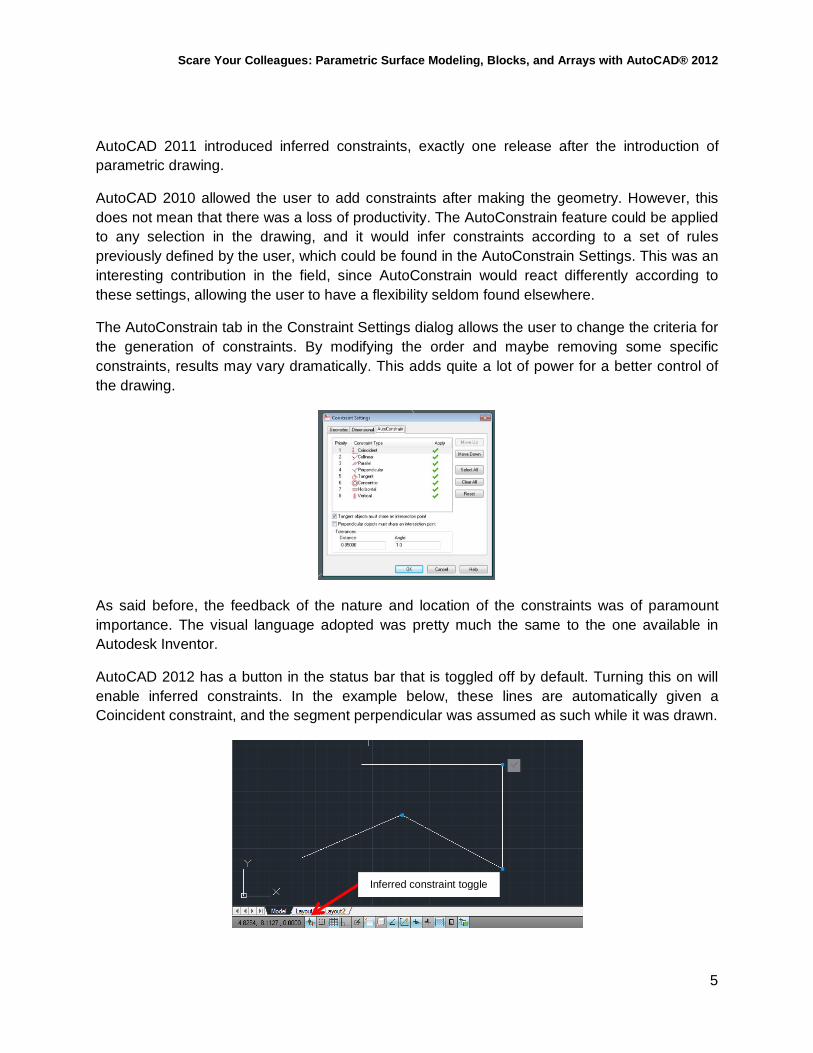
The AutoConstrain tab in the Constraint Settings dialog allows the user to change the criteria for the generation of constraints. By modifying the order and maybe removing some specific constraints, results may vary dramatically. This adds quite a lot of power for a better control of the drawing.
As said before, the feedback of the nature and location of the constraints was of paramount importance. The visual language adopted was pretty much the same to the one available in Autodesk Inventor.
AutoCAD 2012 has a button in the status bar that is toggled off by default. Turning this on will enable inferred constraints. In the example below, these lines are automatically given a Coincident constraint, and the segment perpendicular was assumed as such while it was drawn.
Inferred constraint toggle

Scare Your Colleagues: Parametric Surface Modeling, Blocks, and Arrays with AutoCAD® 2012
6
Not only the constraints can be shown on a per selection basis, but AutoCAD also highlights all of the affected entities. This becomes even more important when a colleague needs to work with a file that has constraints. Any user can quickly understand what’s happening either with the whole drawing or with the part of the drawing in which they need to work.
When the mouse is over the constrained labels, in this case the collinear constraint is highlighted in the label, and is also highlighted in the label at the bottom of this image. The lines affected by the constraints are also highlighted.
Another interesting aspect of the Parametric Drawing feature is that at any time that the user wants to override the constraints, they just need to use the Ctrl key. Doing so will relax the constraint. If the user wants to delete the constraint, it’s as easy as right clicking on the label, and removing the selected constraint.
Dimensional constraints basically create parameters for each constraint applied in the drawing. These constraints can also accept expressions, and you can define User Parameters that can also drive those expressions.
In the example below, the horizontal segment was constrained and named as d1 (default naming for the first constraint). The vertical segment was defined by a simple expression (d2=d1). So any dimensional changes in d1 will impact in d2.

Scare Your Colleagues: Parametric Surface Modeling, Blocks, and Arrays with AutoCAD® 2012
7
The aligned dimension is still a traditional dimension. You can convert it into a constrained dimension.
The focus of this class is on the use of these constraints for surface modeling. For more details on Parametric Drawing, please refer to other AU classes:
AC4772 Introduction to Parametric Drafting in AutoCAD® 2012 John Bordeau
AC4752-L Parametric Drawing: It’s All About Relationships Rick Ellis
AC4360 Applying 2D Parametrics for Cut Sheet Data Ronald Montesano, P.E.
AC3041 Learning Parametric Modeling in AutoCAD® 2012: The Truth Daniel Heselwood
Convert associative dimension

Scare Your Colleagues: Parametric Surface Modeling, Blocks, and Arrays with AutoCAD® 2012
8
Parameters Manager
The Parameters Manager allows us to organize all the dimensional constraints, add Filters to them, and also define User Parameters.
AutoCAD 2010 did not have Filter, so a long list of parameters could become hard to manage. Now you can define as many filters as you want. Then, you only need to drag and drop parameters from the list on the right of the Parameters Manager into the appropriate Group Filter. This is a very smart way to organize the list of parameters.

Scare Your Colleagues: Parametric Surface Modeling, Blocks, and Arrays with AutoCAD® 2012
9
Example Let’s start with a very short example of parametric drawing, so we can understand their use in a real world case scenario. The file gasket1.dwg is part of the class materials. You need AutoCAD 2010, 2011or 2012 in order to open it.
Geometric constraints are shown by entity or for all the drawing. Those controls are in the Geometric panel in the Parametric tab.
You can hover the mouse over each element and understand how it is related to other parts. When you move the mouse over the constraint, it will highlight the related parts. It’s a very simple way to understand the dependencies of the file, especially if it was not done by you.
You can also choose to display the dimensional constraints. Note that both types of constraints will keep their size regardless of the zoom.

Scare Your Colleagues: Parametric Surface Modeling, Blocks, and Arrays with AutoCAD® 2012
10
Expressions can be added or edited from the canvas, the Properties palette, and the Properties Manager.
As mentioned before, we’ll focus on parametric modeling with surfaces. This section was a mere introduction to parametric drawing, with no purpose of going too deep in the many subtleties, which would make it impossible to cover in an hour.

Scare Your Colleagues: Parametric Surface Modeling, Blocks, and Arrays with AutoCAD® 2012
11
2. Parametric Surfaces
For more information on the surface modeling feature, please refer to my class:
AC5413-P The Suite Life of AutoCAD
Using expressions in surfaces
Most of the creation methods for surfaces offer an option for adding an expression to certain parameters. If you display the options when performing the commands, you’ll see a prompt for Expression. Before doing this, you should have at least one User Parameter or a Dimensional constraint in the drawing. Let’s explain this with an example.
Create a spline and a line next to it. Then copy both to the side. Your result should look as follows:
Now let’s add two User Parameters by using the option highlighted below. We’ll name these parameters Angle1 and Angle2. Parameter names can’t have spaces and certain symbols, as happens in other parts of AutoCAD too. Angle1 will be 60 (add 60 under Expression), and Angle2 will be –Angle1/2 (minus half of Angle1). Value indicates the current value based on the expression. The final result should look as follows:

Scare Your Colleagues: Parametric Surface Modeling, Blocks, and Arrays with AutoCAD® 2012
12
Next, we’ll revolve both surfaces, using these User Parameters as values in Expression. For a revolved surface, AutoCAD can drive the angle of revolution as an expression. In the case of an extrusion, it can be the height.
Start the command REVOLVE, select the spline, and then define the line as the axis of revolution (you can do that by using the Object option when defining the axis, or by clicking on two points of the segment). Once you start seeing the revolution, go to the options, and choose Expression. This is when you type Angle1. Just as an interesting note, the parameters are not cap sensitive.
Repeat the same process for the second surface, entering Angle2 as the Expression. You should get a result like the one below (using X-Ray Visual Style, which I highly recommend).

Scare Your Colleagues: Parametric Surface Modeling, Blocks, and Arrays with AutoCAD® 2012
13
Let’s make the example a little more interesting. Use SURFBLEND (Blend) with the top edge of the first surface, and the edge resting on the XY plane of the second surface. You should select one surface edge, click Enter, and then click on the second edge, since Blend can work with multiple surface edges in each set of selections. Add G2 continuity on both sides.
Now we can have some fun by tweaking the value for Angle1, which will impact on the revolution of the second spline, and of course, on the Blend. Use some common sense for the values you edit. If Angle1 is equal to 180 or over that value, then the Expression will be invalid. The Blend can’t be done at 180 with a G2 since both surface edges are coplanar, and Bulge is set to .5 by default. If you change continuity to G0 (or keep G2 and Bulge in 0 –which does not make much sense since it behaves like a G0-), you can continue with the tweaking. Results may be hard to build, anyways.

Scare Your Colleagues: Parametric Surface Modeling, Blocks, and Arrays with AutoCAD® 2012
14
Examples – parametric buildings
In this example we’ll see how to drive a set of trimmed surfaces to create this building.
In this example we will work with a series of lofted surfaces and we’ll drive the lofts based on a set of profiles

Scare Your Colleagues: Parametric Surface Modeling, Blocks, and Arrays with AutoCAD® 2012
15
Best practices
• Dimensional constraints will always be applied on an XY plane, with Z=0. This means that you need to set the UCS in order to constrain a sketch. This is quite normal and taken for granted when you work in applications like Inventor, which have a Sketch Mode. As a best practice, I suggest to use UCS > Object in order to make a fast alignment of the XY plane and the origin to the object you want to constrain. Needless to say, the sketch should be planar.
The dimensional constraints that you can see in the sketch below are all in the XY plane with Z=0. This part is obvious, since the sketch was done by default on that plane.
In this case, the constrained geometry belongs to a circle which is not in the XY plane with Z=0. In order to create this constraint, you first need to align the UCS with that circle.
By using the command UCS and selecting Object, you can then select the circle, and change the UCS position so that it’s aligned with your selection. Then you can apply the dimensional constraint.

Scare Your Colleagues: Parametric Surface Modeling, Blocks, and Arrays with AutoCAD® 2012
16
Constraints can’t be applied between “sketch planes”. Even though AutoCAD does not have a concept of workplane or sketch plane, it may be useful to think about a collection of constraints applied to a sketch as belonging to a specific plane. There can’t be dimensional relationships between those constraints and others located in another plane.
If you need to change the position of the top circle, you can relax the constraint by clicking Ctrl once you have already started moving the circle with the Gizmo (never before using the Gizmo or you will copy the circle).
After the operation finishes, you will have lost the constraint, but you can apply it again by repeating the method explained before.

Scare Your Colleagues: Parametric Surface Modeling, Blocks, and Arrays with AutoCAD® 2012
17
Example
Let’s check an example. Part of it was explained on the best practices. Now let’s build it. The file is available in the materials for the class, and is called iModel.dwg
Draw a circle on the XY plane, and create a Dimensional constraint (Diameter), which will be called Diam. Input 150 as value for Diam, and you’ll see the circle take that diameter.
Now it’s time to be a little creative. Draw another circle, bigger than the previous one, and move it up the Z axis, and then rotate it, so it looks like the image below. If you are not used to the Gizmo, this is a great time to try.

Scare Your Colleagues: Parametric Surface Modeling, Blocks, and Arrays with AutoCAD® 2012
18
If you try to constrain this circle, you’ll fail. You need to be coplanar with an XY plane whose Z=0 contains the sketch. In order to do this, simply invoke UCS, and the option Object. Your UCS will gently move into the appropriate position in order to constrain the circle. Call it Diam_oblique, and make it an expression Diam_oblique=Diam*1.25. We are ensuring it always stays bigger than the circle at the base.
Now draw a Point somewhere near the center of the circle at the base. Then move it up, leaving it over the highest part of the oblique circle. Should look like this.
It’s time to model. We’ll do a loft between the first and second circle, and use the Point as the last element. Go in order from bottom to top, since the order of cross sections is critical in a loft.
After you select the first and second circle, invoke the contextual menu, and select Point. Then you will get something like the image below.
Try changing the values of Diam, and see how the whole model starts reacting. Of course, exercise some common sense with the values. There are always edge cases that may have an error.
The next step will be the patch for the bottom. This is a simple one. Select Patch, and click on the base of the loft. The patch will be a G0. Fast and easy.
Now let’s go for more fun. Draw two circles like the ones you can see in the image above. They are both on the original XY plane. We’ll constrain them now. The names will be Diam_hole_1 for the inner circle and Diam_hole_2 for the outer. The values will be as follow: Diam_hole_1=Diam/5, and Diam_hole_2=Diam/4.

Scare Your Colleagues: Parametric Surface Modeling, Blocks, and Arrays with AutoCAD® 2012
19
It’s time to trim the surfaces. Trim the loft against the outer circle, and the patch against the inner circle. Trimming is simple. Select the surface first, click Enter, and then select the trimming curve (or surface). As soon as you do that, AutoCAD will show you the projection of the circle over the loft, and you need to click on its interior. What you click is what you trim. And the trim is also associative!
Repeat the trim with the patch, and you should have something like the image below.
So how do we keep the trimming circles related to the first two circles? It could be very easy now to make the first circles smaller and have the trim fail if the whole trimming circles are not trimming anything.
First of all, we’ll create a line from the center of the first circle to the center of the two smaller circles. We’ll make them concentric and coincident with the end of the segment. The other end of the segment will be coincident with the center of the first circle. Now the two circles move together if we move the segment. But we also need to constrain the segment. Let’s add a dimensional constraint. It will be an Aligned constraint. It will be called distance_hole, and its value will be distance_hole=Diam/3. In this way, we are ensuring that the two circles always stay inside the first circle. Try moving the segment around. It will be forced to describe a circle around the first circle’s center.
Finally, we want to control the position of the holes. This is tricky. We’ll draw a vertical segment that ends in the center of the first circle, and it’s coincident with it. And we’ll also add a geometric constraint to this segment (Fix). The segment can’t move. The first circle can’t move either. It can only change its diameter, which will change all the other circles. Why did we fix it? Because we will now add an angular constraint between both segments. If we don’t fix one of them, it will be hard to control who’s moving.
Add an angular constraint, called Angle. Its value will be Angle=150. Try changing the value, and you will be able to see how the trims change position.
The final step will be a blend between the two edges of the trimmed surfaces. The blend will have G2 on both sides. We’re done. You have a set of parametric surfaces!

Scare Your Colleagues: Parametric Surface Modeling, Blocks, and Arrays with AutoCAD® 2012
20

Scare Your Colleagues: Parametric Surface Modeling, Blocks, and Arrays with AutoCAD® 2012
21
3. Making 3D blocks with parametric surfaces
So, if we have parametric capabilities in surfaces, and they are associative, can we make a block with them? Sure!
In this final example, we’ll go back to the gasket, and we’ll create a 3D parametric block. If it was not for rigor’s sake, I’m tempted to call it a 3D dynamic block. Since solids and meshes can’t participate, let’s stay out of that name. Names aside, a 3D parametric block is already powerful enough.
The file can be found in the material for the class. It’s called gasket10.dwg

Scare Your Colleagues: Parametric Surface Modeling, Blocks, and Arrays with AutoCAD® 2012
22
Working in the block editor
The main difference when building a parametric block is that we will apply the constraints inside the block editor. You can also create the drawing in the model space, and then create a block with it. You will continue in the block editor.
There is another difference we need to consider. If we plan to control the block from outside of the block editor, then we have to create User Parameters inside the block editor, and drive constraints with these. User Parameters will appear on the properties palette when selecting the block if we follow this rule.
Adding data from Excel
We’ll also add an interesting feature to this block. We’ll get data from an Excel spreadsheet in order to populate the block table, and have a very organized parametric block which can contain a whole catalog of sizes, provided that the geometry is maintained.
User Parameters become important again. These are the parameters that can appear in the block table, and which will be filled when we do a copy paste from Excel.
We’ll see all this in the example below.
Example
The first step will be to create a block with the gasket from the model space. Let’s call it… gasket. The insertion point could be the center of the circle that is drawn as construction geometry. Open the block editor.
My customization has the same background color on the block editor. You can do this from Options.
Let’s take a look at the geometry of the block and at the options in the Ribbon. We have both geometric and dimensional constraints, in case we need them. The traditional authoring palettes are also available. When working with parametric surfaces, it is better not to mix methods, since they are controlled with different logic.
You can also see an option called Block Table, where we’ll populate the catalog.

Scare Your Colleagues: Parametric Surface Modeling, Blocks, and Arrays with AutoCAD® 2012
23
The other interesting option is Test Block. This was also available for AutoCAD 2010, and makes it easier to try a block, without having to exit the Block Editor, insert the block, see how you failed (at least this tends to happen the first time), and start again.
Let’s take a closer look at the Parameters Manager. I added four User Parameters. Three will be used for the sketch’s geometry, and the last one for the height of the extrusion.

Scare Your Colleagues: Parametric Surface Modeling, Blocks, and Arrays with AutoCAD® 2012
24
Some aspects to consider:
• The user parameters have numeric values because they are driven by values from the spreadsheet.
• The user parameters are only used on the expressions. You can’t repeat the same names you used on the dimensional constraints.
• If you need a dimensional constraint to be the same value as a user parameter, then create an expression like this: [dimensional constraint]=[user parameter]
Once you have these values, we’ll add a block table. Click the icon on the Ribbon, and locate the block table somewhere in the drawing. You may want to consider that the location of the block table is basically where you are going to see the control that lets you change the values when you insert the block. You probably don’t want the block table too far away, or blocking the view of your block.
Now let’s go to the table. You will also need the spreadsheet with the values. In the Block Properties table, click on Add Properties which will appear as columns of the table.

Scare Your Colleagues: Parametric Surface Modeling, Blocks, and Arrays with AutoCAD® 2012
25
You should see all your user parameters in the list. Select all of them except the Height.
You should now have three columns on the table. You could simply input values there. But if you have a spreadsheet with data, then it’s much faster. Make sure that the columns are ordered in the same way. You can change the position of the columns by simply dragging them.
Now copy and paste the selection into the first cell of the table in AutoCAD, and click OK. You have a complete table for the block!
Scare Your Colleagues: Parametric Surface Modeling, Blocks, and Arrays with AutoCAD® 2012
26
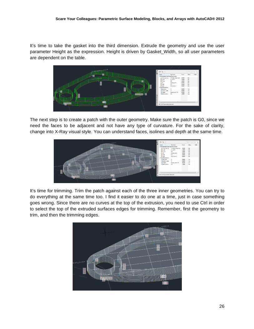
It’s time to take the gasket into the third dimension. Extrude the geometry and use the user parameter Height as the expression. Height is driven by Gasket_Width, so all user parameters are dependent on the table.
The next step is to create a patch with the outer geometry. Make sure the patch is G0, since we need the faces to be adjacent and not have any type of curvature. For the sake of clarity, change into X-Ray visual style. You can understand faces, isolines and depth at the same time.
It’s time for trimming. Trim the patch against each of the three inner geometries. You can try to do everything at the same time too. I find it easier to do one at a time, just in case something goes wrong. Since there are no curves at the top of the extrusion, you need to use Ctrl in order to select the top of the extruded surfaces edges for trimming. Remember, first the geometry to trim, and then the trimming edges.

Scare Your Colleagues: Parametric Surface Modeling, Blocks, and Arrays with AutoCAD® 2012
27
Once you repeat the process on the bottom, you are done. Please note that copying the top patch on the bottom does not work, since it would not be associative.
Close the block editor, and insert the gasket. Click on it, and see the table. Check how it responds to all the changes in values. This is an immense time saver. You just have one block, it’s 3D (you have both the curves and the model, and if you create them in separate layers, you can display it as 2D or 3D), you don’t have to host many blocks with Visibility (which is how you would have done this with Dynamic Blocks).
If at the very end you need a solid, you can explode the block, and use SCULPT. Remember that by that time, there is no block, and no associativity.

Scare Your Colleagues: Parametric Surface Modeling, Blocks, and Arrays with AutoCAD® 2012
28
4. Associative array with AutoCAD 2012
Associative array is one of the main features in AutoCAD 2012, and completely leverages the associative framework we already mentioned.
It also introduces a new array called Path Array (ARRAYPATH). You have probably used MEASURE and DIVIDE more than once for adding blocks into a segment. This array takes this idea into a complete next level.
Let’s start with the basics.
The new array interacts via command prompt upon first creation and via the Ribbon after it has been done.
The old ARRAY can also be now accessed via three new commands: ARRAYRECT, ARRAYPOLAR, ARRAYPATH.
The first two are the well-known rectangular and polar array. If you miss the old dialog, you can get it if you install AutoCAD 2012 SP1. It is called ARRAYCLASSIC. However, this creates a non-associative array.

Scare Your Colleagues: Parametric Surface Modeling, Blocks, and Arrays with AutoCAD® 2012
29
Using associative arrays
Let’s see a short example that covers polar and path array. We’re going to build a spiral staircase in a couple of clicks.
We’ll start with a couple of circles and a line, which we will array around the circle.
After creating the polar array, we now have controls that allow us to make several edits (count, revolve angle, etc)
Once you have created the array, it will become a single object called array. It’s basically become some sort of block. If you select any part of the array, you will see the contextual Ribbon

Scare Your Colleagues: Parametric Surface Modeling, Blocks, and Arrays with AutoCAD® 2012
30
Now let’s use Press Pull to extrude one of the steps. We’ll have a solid, which we now want to array along a 3D Helix we’ll create.
After these few steps, we have the basics of a spiral staircase. Pretty easy. And we have not yet untapped the potential of adding parameters to all this operation.
Path array will prompt for the object to array and the path. You can then define the base point, amount of objects, and different alignments. We’ll cover these options in different examples.

Scare Your Colleagues: Parametric Surface Modeling, Blocks, and Arrays with AutoCAD® 2012
31
The combination of these different arrays may lead us to examples like the one below, where we’ll check out some interesting features.
In the case of this bridge, the road is defined by a SWEEP (as a surface, patched on both ends), and then it’s a set of pillars and lampposts using the same path of the spline, and an path array. The interesting thing is that we can then move the spline, add vertices, or whatever else you feel you need to do to the path, and it will update both the road and the elements arrayed on top of it.
TIP: since a sweep will try to regen the surface while dragging, this can cause serious performance issues. I suggest to set SURFACEASSOCIATIVITYDRAG to 0, so the sweep only regens after releasing the gizmo.
Another interesting thing about the array is that we can keep building the content after it’s done. If we select the array, we’ll see options for editing the source.
If we select to edit the source, we will be able to add/remove detail from the array. In the case of this bridge, I first built the basic array with the pillar, and then added the foundations. Once I add it to the part of the array I’m editing, then every element gets the same treatment. Consider this as a redefinition of a block. TIP: Since the array behaves like a block, a way to copy a nested element is through NCOPY. TIP: We can also select an individual part of the array by accessing sub object level. As you may already know, this is done in AutoCAD by using Ctrl while you select an object. Then you’ll be able to move, rotate and delete the object. Note that if you then edit the array, depending on the edit you make, you may have issues with the part you displaced or deleted. For example, you edit the array so it has less elements, and the displaced/deleted part was in the area of

Scare Your Colleagues: Parametric Surface Modeling, Blocks, and Arrays with AutoCAD® 2012
32
elements that are removed by reducing objects. If you then go back to having more objects, the array won’t be able to replicate your past status with displaced/deleted objects. Another interesting edit is to replace an object or even all objects in the array. Simply select Replace Item within ARRAYEDIT, select the object that you want to add, and then click on the objects of the array that need to be replaced. You can also replace all elements by following the prompts. Let’s see an example. I just made an NCOPY of a lamppost, and did a copy/rotate, so I could get a different one.
Now I’ll replace the lamppost by using Replace Item. Very simple task.

Scare Your Colleagues: Parametric Surface Modeling, Blocks, and Arrays with AutoCAD® 2012
33
Using expressions in associative arrays
Let’s now add some parametric power to the array. We can work with the Parameter Manager and add expressions that will drive the array.
In the example below we can see some steps with a set of railings. This is quite common at the access to an arena. In this example we can tweak the size of the steps, the curvature of the stairs, and the amount of railings
Here are the parameters used for the stairs. There are some geometric constraints that will drive the size of the riser and the treads. The segments have all a Coincident constraint, and the whole set of segments have the bottom point of the first riser with a Fix constraint. This means that we can control the direction this whole thing move.

Scare Your Colleagues: Parametric Surface Modeling, Blocks, and Arrays with AutoCAD® 2012
34
We also added a User Parameter called balusters, which will drive the number of railings. We’re ready to create the array. But first we’ll do a sweep using an arc (the path) and the profile for the steps. Since the surfaces are set to Associative, a change in the arc will change the steps. We can also try and change the values of d1 (tread) and d2 (riser). All works. The railing is also a set of segments contrained to move with the steps. The two bottom vertices of the future path of the balusters have a Coincident constraint with the risers, so when the steps move, the balusters move. In order to add expressions within the array, we need to check the prompts for Expression. See below.
The path array has a feature very useful for this case. When you add Rows (which are going to be like an offset from the path), you are also allowed to add an Incrementing Elevation. For the latter, you will use the Expression d2, which already drives the height of the riser. The distance between levels will be driven by d1 (the length of the tread)

Scare Your Colleagues: Parametric Surface Modeling, Blocks, and Arrays with AutoCAD® 2012
35
5. Conclusions
• Parametric 3D blocks only work with surfaces. There is no associativity for solids or meshes.
• Make sure you expose the values you need to control in the block as user parameters. • When creating constraints, these always have to be in an XY plane in Z=0. UCS by
object will become your best friend for this operation. • Make sure not to overconstrain or to underconstrain. Both scenarios lead to trouble. • Use auxiliary geometry that you can then hide. In many cases, you may want to fix this
geometry. • If the end goal is to get a solid, you can convert the exploded geometry into a solid by
sculpting the surfaces.