scan2000 - scan steering is based on the dynamically tuned gyroscope which provides for better...
TRANSCRIPT

SCAN2000
Ver. 15. February 2001
Operation and
Installation manual

SCAN 2000 OPERATION & INSTALLATION MANUAL February 2001
SCAN-STEERING Page 2
CONTENTS
PART I (Practical Information) 1. INTRODUCTION ................................................................................................. 3 2. MAIN UNIT .......................................................................................................... 4 3. ELECTRONIC UNIT ............................................................................................ 5 4. CONTROL UNIT .................................................................................................. 7 5. INSTALLATION................................................................................................... 8
5.1. Unpacking of Gyrocompass ............................................................................ 8 5.2. Installation of Main Unit ................................................................................. 8 5.3. Installation of Electronic Unit ......................................................................... 9 5.4. Installation of Control Unit ............................................................................. 9 5.5. Interconnection of Units and Power Supply.................................................. 10
6. OPERATING PROCEDURE.............................................................................. 11 6.1. Setting the latitude......................................................................................... 12 6.2. Setting the Speed ........................................................................................... 12 6.3. Using the dimmer .......................................................................................... 13
7. ALARM AND REPAIR ...................................................................................... 13 8. TECHNICAL DATA........................................................................................... 14 9. PLUG CONNECTIONS...................................................................................... 17 PART II (Description) 10. DESCRIPTION INTRODUCTION................................................................... 19 11. APPLICATION ................................................................................................. 20 12. GYROCOMPASS COMPOSITION ................................................................. 21 13. DESIGN AND OPERATION OF GYROCOMPASS....................................... 21 14. DESIGN OF GYROCOMPASS COMPONENTS............................................ 24 PART III (Drawings) 15. CONNECTION DRAWING ............................................................................. 34 16. INSTALLATION DRAWINGS ........................................................................ 35 17. CABLE DIAGRAMS (3 included cables)......................................................... 37 PART IV (Spareparts) 18. SPAREPART LIST ........................................................................................... 40 PART V (Distribution box) 19. OPTIONAL NMEA DISTRIBUTION BOX..................................................... 41 PART VI (Connecting to existing Scan-Steering equiptment) 20. CONNECTING SCAN 2000 TO EXCISTING HE 550/600 AUTOPILOT..... 42

SCAN 2000 OPERATION & INSTALLATION MANUAL February 2001
SCAN-STEERING Page 3
1. INTRODUCTION
The present Manual contains all necessary information on installation, technical maintenance,
and operation of gyrocompass SCAN 2000.
SCAN 2000 is used for indication of heading on all type of sea- and river going vessels with
speed up to 90 Knots. It is based on the dynamically tuned gyroscope which provides for
better accuracy and reliability of operation and simplifies the maintenance of SCAN 2000
(there is no need in flotation fluid change, extra heating or cooling, etc. which is required in
nearly all other types of gyrocompasses).
The basic model of SCAN 2000 incorporate the following units:
- Main Unit
- Electronic Unit
- Control Unit
The vessel's true heading can be read directly from the top or side of compass card of the
Main Unit or from the digital display of the Control Unit. The output signals are either in
international NMEA 0183 RS232/422 code or in the form of STEP voltage (6 steps/degree).
SCAN 2000 has automatic adjustment of speed and latitude when interfaced with GPS
Navigator. Further speed and latitude can be adjusted manually. SCAN 2000 defines the
heading against geographical meridian at the vessel speed up to 90 knots and latitude of
navigation up to 75 degrees. Alignment of SCAN 2000 against meridian is made
automatically.

SCAN 2000 OPERATION & INSTALLATION MANUAL February 2001
SCAN-STEERING Page 4
2. MAIN UNIT
The Main Unit (Fig. 1) is a single-rotor adjusted gyrocompass based on a two-degree-of-
freedom dynamically tuned gyroscope (DTG). DTG is rigidly secured to the inner gimbal of
two-gimbal assembly. The outer gimbal has unlimited rotation in azimuth. The gimbal
assembly is temperature stabilized. The compass card is mounted on top of the outer gimbal.
The scale reads to 1 degree and is numbered from 0O to 360O every 10 degrees.
The casing of the Main Unit is comprised of a base and a transparent cover under which the
compass card is located. Inside the Main Unit there is a gyro platform onto which the
gyroscope and the accelerometer are secured by screws. Torques are mounted on the axes of
the gimbal assembly. Two-degree-of-freedom suspension provides for the movement of the
platform in horizontal and azimuth planes. Electrical signals are transmitted along the
horizontal axes by flexible wires led through the hollow journals, along the vertical axes -
with the help of a commentator.
There are two cable connectors for external cables in the lower part of the base, which connect
the Main Unit with the Electronic Unit.
Longitudinal axis of the device is marked by two notches on the base.
Main unit Fig. 1.

SCAN 2000 OPERATION & INSTALLATION MANUAL February 2001
SCAN-STEERING Page 5
3. ELECTRONIC UNIT
The Electronic Unit (Fig. 2) is an analog-digital computer, which generates updating and
control signals and secondary voltages necessary for the Main Unit operation. The Electronic
Unit performs conversion of analog heading data into digital code.
The Electronic Unit contains 10 electronic circuit boards which are enclosed in a rectangular
casing and secured by screw.
- Azimuth Channel Stabilization Amplifier Board
- Horizontal Channel Stabilization Amplifier Board
- Control Board
- Step Voltage Generation Board
- Conversion into NMEA 0183 Board
- Speed Input Board
- Heading Transformer Board
- Timer Board
- Gyro Motor Supply Board
- GPS Input Board
- Supply Unit.
Electronic unit
Fig. 2.

SCAN 2000 OPERATION & INSTALLATION MANUAL February 2001
SCAN-STEERING Page 6
In front of the Electronic Unit there is a lock that secures the top cover. Under the top cover,
face sides of electronic circuit boards, two fuses, two potentiometers for gyro azimuth and
horizontal drift compensation, two potentiometers for temperature component of gyro azimuth
and horizontal drift compensation and mode selector are located.
On the left side of the casing there are nine electronic connectors for external cables. The
Electronic Unit is connected to the Main Unit and the Control Unit. The power cable must be
connected to the vessel's Mains: 24V DC, or to the optional PS 220 Power Supply.
When the cover of the Electronic Unit is opened (Fig. 2.1), there are two fuses, fuse1 is the
main fuse (5A), if this fuse is faulty, a red LED near the fuse will show.
Fuse2 is the fuse for step output (2A).
The switch (normal/test mode) located near fuse2, should always be in position NORMAL. Test mode is used only for factory adjustment.
Electronic Unit
Fig. 2.1.

SCAN 2000 OPERATION & INSTALLATION MANUAL February 2001
SCAN-STEERING Page 7
4. CONTROL UNIT
The Control Unit (fig. 3) performs operation control and indication of input and output data.
On the front panel of the Control Unit (fig. 3) there are:
- digital heading indication display
- indicator of readiness for operation "READY"
- general failure indicator "FAILURE"
- GPS failure indicator
- 24V Dc power failure indicators
- two buttons for "NORTH" and "SOUTH" latitude
- power on/off buttons "START" and "STOP"
- two multi-position speed control "SPEED"
- two multi position latitude control "LATITUDE"
Speed control "SPEED" has a position for an automatic input of vessel's speed from the GPS.
Control unit
Fig. 3.

SCAN 2000 OPERATION & INSTALLATION MANUAL February 2001
SCAN-STEERING Page 8
5. INSTALLATION Installation and assembly of SCAN 2000 devices on the vessel can be performed after all construction, painting and decorating works are over. Diagram of connections is given in Fig. 9 on page 34.
5.1. Unpacking of Gyrocompass Unpacking of the equipment should be done with care A visual inspection should be made to see that the equipment has not been damaged during shipment. All buttons and controls should be checked for freedom of movement.
5.2. Installation of Main Unit
The Main Unit is mounted on a rigid metal foundation without amortization and is secured
with three 8 mm bolts through the oval holes in the casing (fig.10, p35).
It is recommended to place the Main Unit as close to the vessel's center of mass as possible so
that deviations do not exceed:
- vertical axis +/- 10 m
- pitch axis +/- 5 m
- horizontal axis +/- 80 m
Absence of sudden temperature fluctuations is desirable. Sufficient free space around the
Main Unit should be provided for service and maintenance operations.
The Main Unit is placed in such a way that its longitudinal axis marked by two notches on the
base is parallel to the centerline of the vessel. The accuracy of positioning should not be worse
than +/- 0.25O
Cable connectors of the Main Unit should face the bow of the vessel.

SCAN 2000 OPERATION & INSTALLATION MANUAL February 2001
SCAN-STEERING Page 9
5.3. Installation of Electronic Unit
The Electronic Unit can be installed remotely from the Main Unit, but within two meter. It is
secured with the help of a bracket or directly to the panel side with four 6 mm bolts.
During installation mind, please, that cable connectors located on the left side of the
Electronic Unit must look downwards. It is important that there is easy access to the unit, for
service reasons.
Also GPS NMEA input needs to be configured, either for RS422 input or RS232 input, this is
done directly on the GPS PCB. Dipswitch setting is shown on PCB.
5.4. Installation of Control Unit The Control Unit is secured to some vertical or horizontal plane on the vessel with the help of rotating bracket which ensures rotation of the casing about longitudinal axis. The bracket is secured with four 6 mm bolts. The cable connector for the external cable is located on the bottom of the Control Unit casing. It is recommended to install the Control Unit near the working place of the navigator to ensure convenient operation of switches and buttons.
SCAN 2000 OPERATION & INSTALLATION MANUAL February 2001
SCAN-STEERING Page 10
5.5. Interconnection of Units and Power Supply
The Interconnection between the units of SCAN 2000 is made by means of cables with
hermetized multiple-contact connectors. The required cables are supplied with SCAN 2000.
Before switching on SCAN 2000 please secure that all cable interconnections and earthing are
correct and reliable.
Observe the polarity of the mains. Input supply voltage should be between the limits 19.0 and
29.0 Volts. Capacity of the power supply should not be less than 100 W.
SCAN 2000 OPERATION & INSTALLATION MANUAL February 2001
SCAN-STEERING Page 11
6. OPERATING PROCEDURE
After all the units of SCAN 2000 have been located and secured, and the power cable has been connected: - set SPEED control on Control Unit in "0" position - set LATITUDE control on the Control Unit to the latitude of the vessel - press START button on the Control Unit.
- Set hemisphere to ether "NORTH" or "SOUTH" by using the pushbuttons on the front of the control unit
The value of the heading displayed on the Control Unit reflects the position of the gyroscope against the vessel's center plane at the moment of switching-on. Alignment of SCAN 2000 against meridian is done automatically. Time of alignment depends upon the initial angular deflection of gyroscope from meridian and starting environmental conditions (temperature, initial position latitude, angle of tilt of the base) and takes up to 45 min. When the alignment procedure is over the green READY indicator on the front panel of the Control Unit comes on and the display will show the true heading. Maximum allowable error is ±0.7O. When operating from the GPS, set the SPEED and LATITUDE control to the "GPS" position. To switch off the SCAN 2000 press the "STOP" button on the front panels of the Control Unit. The SCAN 2000 gyrocompass is completely stopped after 5 min.
SCAN 2000 OPERATION & INSTALLATION MANUAL February 2001
SCAN-STEERING Page 12
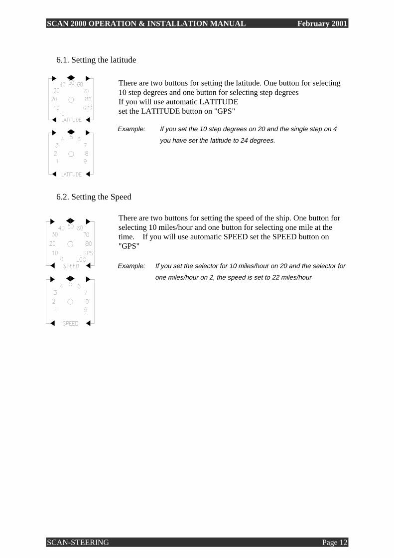
6.1. Setting the latitude
There are two buttons for setting the latitude. One button for selecting 10 step degrees and one button for selecting step degrees
If you will use automatic LATITUDE set the LATITUDE button on "GPS" Example: If you set the 10 step degrees on 20 and the single step on 4
you have set the latitude to 24 degrees.
6.2. Setting the Speed
There are two buttons for setting the speed of the ship. One button for selecting 10 miles/hour and one button for selecting one mile at the time. If you will use automatic SPEED set the SPEED button on "GPS"
Example: If you set the selector for 10 miles/hour on 20 and the selector for
one miles/hour on 2, the speed is set to 22 miles/hour

SCAN 2000 OPERATION & INSTALLATION MANUAL February 2001
SCAN-STEERING Page 13
6.3. Using the dimmer
The dimmer button controls the light in the control box
Example: Turn the button clock ways and the light will increase and visa
versa
On the Main Unit there is also located a dimmer, for regulation of illumination of the top
scale. The dimmer is located on the foundation of the Main Unit. Functionality is the same as
the dimmer located on the Control Unit.
7. ALARM AND REPAIR
SCAN 2000 has built-in test system for fault isolation. In case of failure fault signal is generated and the indicator "FAILURE" lights up on the front panel of the Control Unit. When the fault is detected, press STOP button on the front panel of the Control Unit to turn off SCAN 2000. Check the voltage in the mains, make certain that the setting of latitude and speed are correct and after 2 - 5 minutes restart SCAN 2000. If the FAILURE indicator remains on the failure is permanent and you must contact an authorized Service Center. Repair or replacement of the fault parts is performed by the authorized specialist from the Service Center, except the case when the reason of failure is the blown fuse located under the cover of the Electronic Unit.
SCAN 2000 OPERATION & INSTALLATION MANUAL February 2001
SCAN-STEERING Page 14
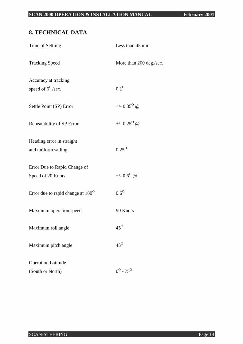
8. TECHNICAL DATA
Time of Settling Less than 45 min.
Tracking Speed More than 200 deg./sec.
Accuracy at tracking
speed of 6O /sec. 0.1O
Settle Point (SP) Error +/- 0.35O @
Repeatability of SP Error +/- 0.25O @
Heading error in straight
and uniform sailing 0.25O
Error Due to Rapid Change of
Speed of 20 Knots +/- 0.6O @
Error due to rapid change at 180O 0.6O
Maximum operation speed 90 Knots
Maximum roll angle 45O
Maximum pitch angle 45O
Operation Latitude
(South or North) 0O - 75O

SCAN 2000 OPERATION & INSTALLATION MANUAL February 2001
SCAN-STEERING Page 15
GPS input for auto latitude and speed NMEA 0183 RS232/422 (4800,8,n,1)
$xxGLL,aaaa.aa,b,ccccc.cc,d
$xxVTG,x.x.T,x.x,M,e.e,N,x.x,K
(a = Latitude, b = N / S, c =
Longitude, d = E / W, e = speed in
System Outputs NMEA 0183 RS 422 (4800,8,n,1)
$HEHDT,xxx.x,T<CR>,<LF>
24Vdc Step (6 steps/degree)
Positive Common
Error of heading data transmission
the repeaters does not exceed : 0.1 deg. (NMEA output).
0.2 deg. (STEP output).
Power Input 24V DC
Power Consumption Max. 50 W (Start-up Mode)
Max. 30 W (Ready)
Operating Temperature From - 10 to + 55OC
Relative Humidity Up to 98% at + 40OC
Base Vibration Frequency with
Acceleration up to 10 m/sq.s 5 - 80 Hz
Horizontal Acceleration at
Vessel Swinging Up to 1 m/sq.s

SCAN 2000 OPERATION & INSTALLATION MANUAL February 2001
SCAN-STEERING Page 16
Weight:
Main Unit 10 Kg
Electronic Unit 12 Kg
Control Unit 4.5 Kg
NOTE: The following optional power supply of GC is available:
- PS220 : 110 - 220 Vac 50/60 Hz power supply with automatic
switch over to emergency 24Vdc supply
SCAN 2000 OPERATION & INSTALLATION MANUAL February 2001
SCAN-STEERING Page 17
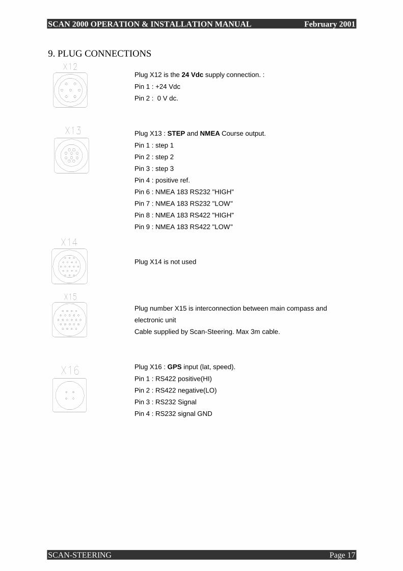
9. PLUG CONNECTIONS
Plug X12 is the 24 Vdc supply connection. :
Pin 1 : +24 Vdc
Pin 2 : 0 V dc.
Plug X13 : STEP and NMEA Course output.
Pin 1 : step 1
Pin 2 : step 2
Pin 3 : step 3
Pin 4 : positive ref.
Pin 6 : NMEA 183 RS232 "HIGH"
Pin 7 : NMEA 183 RS232 "LOW"
Pin 8 : NMEA 183 RS422 "HIGH"
Pin 9 : NMEA 183 RS422 "LOW"
Plug X14 is not used
Plug number X15 is interconnection between main compass and
electronic unit
Cable supplied by Scan-Steering. Max 3m cable.
Plug X16 : GPS input (lat, speed).
Pin 1 : RS422 positive(HI)
Pin 2 : RS422 negative(LO)
Pin 3 : RS232 Signal
Pin 4 : RS232 signal GND

SCAN 2000 OPERATION & INSTALLATION MANUAL February 2001
SCAN-STEERING Page 18
Plug number X17 is interconnection between main compass and
electronic unit
Cable supplied by Scan-Steering. Max 3m cable.
Plug number X18 is not used
Plug number X19 is interconnection between control unit and
electronic unit.
Cable supplied by Scan-Steering. Max 3m cable.
Plug number X20 is not used

SCAN 2000 OPERATION & INSTALLATION MANUAL February 2001
SCAN-STEERING Page 19
10. DESCRIPTION INTRODUCTION
The present Description is intended for the study of the article, its operating principle, design
and application.
The following abbreviations and symbols are used in this Description:
GC - Gyro Compass
AA - Automatic Adjustment
DG - Directional Gyro
FSSAB - Follow-up Stabilization Systems
Amplifier Board
GMSB - Gyro Motor Supply Board
VVDRB - Vessel s Velocity Data Reception Board
VHDFB - Vessel s Heading Data Forming Board
in Interface NMEA 0183 RS232/422
SVFB - Step Voltage Forming Board
ϕ - Latitude of Vessel Location
R - Radius of the Earth
K - Vessel Heading
V - Vessel Velocity
K1, K2 - Weighting Factors
ωdr.x,�ω dr.z - Steady Components of Gyro Drift
Ucomp1, - Temperature Dependent Components
Ucomp2 of Gyro Drift
U - Angular Speed of Diurnal Earth Rotation
ωcorr.z - Angular Speed of Azimuth Correction
ωcorr.x - Angular Speed of Horizontal Correction
Krc (Kro) - Rough Course

SCAN 2000 OPERATION & INSTALLATION MANUAL February 2001
SCAN-STEERING Page 20
11. APPLICATION
The Scan 2000 Gyro Compass (GC) is designed for the indication of the heading of sea/river
vessels.
GC provides:
- definition of vessel heading.
- automatic heading data transmission to analog and digital receivers.
GC is designed to operate in the following conditions:
- ambient temperature from - 10C to + 55 C
- relative humidity up to 98% at temperature of +40C
- base vibration with acceleration up to 10 m/sq.s from 5 to 80 Hz
- horizontal acceleration of vessel swinging up to 1 m/sq.s
- angular speed of vessel yawing more than 200 deg/s;
- magnetic fields (steady and variable) up to 80 A/m.
GC holds its parameters without any adjustment under the influence of the following factors:
- ambient temperature from -60 to +70 C (for the Main Unit from
-50 to +70 C.
- base vibration with acceleration up to 10 m/sq.s from 5 to 80 Hz;
- long vessel tilts at angles of 45 degrees;
- angular speed of vessel yawing more than 200 deg/s;
- blows with acceleration up to 100 m/sq.s and pulse duration 10-15 ms.

SCAN 2000 OPERATION & INSTALLATION MANUAL February 2001
SCAN-STEERING Page 21
12. GYROCOMPASS COMPOSITION
The basic Scan-2000 Gyrocompass incorporates the following units :
- Main unit (MU)
- Electronic Unit (EU)
- Control Unit (CU)
13. DESIGN AND OPERATION OF GYROCOMPASS The functional diagram of gyrocompass is given in Fig.7,p32. The Scan-2000 is a single-rotor adjusted gyrocompass based on dynamically-tuned gyroscope (DTG). DTG is mounted on the platform with the two-degrees-of-freedom suspension DTG is rigidly secured on the inner frame of suspension so that the frame rotation axis lies along the DTG rotation axis. Inside DTG there are sensors which under misalignment of DTG rotor and casing in mutually perpendicular planes generate signals proportional to the angles of misalignment. These signals are amplified and transmitted to stabilization motors ACψ and ACk, mounted on the axes of inner and outer frames. Motors ACψ and ACk drive misalignment signals to the null position and stabilize suspension frames in space. In response to the signals from the Electronic Unit torquers AMx and AMz control gyroscope position. These torquers generate control and slaving moments along the axes of the inner frame. Torquers AMx and AMz are built-in, in the DTG. Horizontal Indicator (HI) (accelerometer) ATN-S is mounted on the inner frame. HI generates the signal proportional to the angle of descend of gyroscope with reference to the horizontal plane.

SCAN 2000 OPERATION & INSTALLATION MANUAL February 2001
SCAN-STEERING Page 22
βω 22.cos KUcompxdrKR
VUx +++=
ϕβωϕϕ
cos
11.sinsin
KUcompzdrKtg
R
VUUz ++++=
ϕKgtR
Vsin K
R
Vcos
DTG requires highly accurate system of stabilization. Thus, stabilization system´s static error
of the order of 1" results in steady drift with angular speed of 0.02 deg./h.
Stabilization System consists of pick-offs of DTG, control electronic circuit boards and direct
drive motors.
Main features of stabilization system :
- direct drive motor.
- steady disturbing moments compensation.
- pulse-width modulation.
Control moments generated by signals of horizontal indicators and slaving moments generated
by signals of Control Board in accordance with latitude and velocity are imposed directly on
gyro rotor axis and bring it to the meridian and horizont. At a steady position the following
voltages are applied to the torquers.
Correction circuit of the Control Board generates voltages proportional to the Earth rotation
speed component Usinϕ , vessel velocity components
and
and then they are applied to the inputs of corresponding adders. The value of horizontal
indicator signal determines voltages proportional to K1β and K2β. After amplification they
are also applied to the adders which create voltages on torquers AMx and AMz. Sensitive
element (DTG) axis is oriented against the North by K1β signal (directing moment is created).
Sensitive element axis is leveled by K2β signal (damping moment is created).
SCAN 2000 OPERATION & INSTALLATION MANUAL February 2001
SCAN-STEERING Page 23
Temperature compensation circuit generates components of gyroscope drift Ucomp1, Ucomp2
which depend upon the ambient temperature. Temperature compensation circuit consists of
temperature sensor, which is mounted on the platform next to DTG, and amplifier which has
direct and inverse outputs with amplification adjustment.
Temperature compensation signals are applied to the torquers of gyroscope in accordance with
its temperature characteristics. ωdr.z and ωdr.x are set manually with the help of
potentiometers.
Motors ACψ and ACk placed on the axes of DTG suspension bring
suspension frames into position which is slaved to DTG rotor axis. Simultaneously azimuth
motor ACk turns two course detectors CKTA and CKT. CKTA is intended for signal-to-code
conversion. CKT outputs correcting signals into translator.
Heading data received from CKTA are converted into 14-bit parallel code on the Heading
Transformer board which is then transmitted to the former of international code NMEA
version 0183 R232/422. After that it goes to the users and to the Control Unit display.
Data on latitude and vessel velocity are when set manually by using the toggle switches on the
Control Unit received by Control Board in the form of analog signals: V, sinϕ and cosϕ.
When using an external GPS unit for latitude and velocity, the NMEA 0183 signal from GPS
goes into the GPS board, where latitude is transformed into analog signals: sinϕ and cosϕ.
Vessels velocity is transformed into an 8 bit binary signal. Both signals are transmitted to the
Control Board.
The mode of velocity and latitude data input (auto or manual) is set by command from
Control Unit. The toggle switches is set into position GPS for automatic latitude and velocity
input. In manual mode the Speed of vessel and latitude of the place is to be set.

SCAN 2000 OPERATION & INSTALLATION MANUAL February 2001
SCAN-STEERING Page 24
14. DESIGN OF GYROCOMPASS COMPONENTS
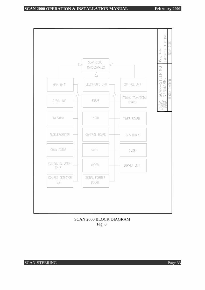
The block diagram of the SCAN 2000 Gyrocompass is given in the Fig. 8, p33.
The Main Unit includes the following units:
- sensitive element, dynamically tuned gyroscope (DTG).
- accelerometer AT.
- two torquers AMx, AMz.
- course detectors CKTA, CKT.
- commutator.
- damper.
Electronic Unit is an analog-digital computer which generates correcting and control signals
and secondary voltages necessary for operation of the Main Unit.
Besides, Electronic Unit performs conversion of analog heading data into digital code which
is used by the different devices.
Electronic Unit includes the following articles:
- FSSAB of azimuth channel.
- FSSAB of horizontal channel.
- Control Board.
- SVFB.
- NMEA 0183 RS232/422 VHDFB.
- VVDRB.
- Heading Transformer Board.
- Timer Board.
- GMSB.
- GPS Board.
- Supply unit.

SCAN 2000 OPERATION & INSTALLATION MANUAL February 2001
SCAN-STEERING Page 25
β2K ϕβ
cos
1K
FSSAB contains the components of gyro platform stabilization systems at angles K and ψ.
FSSAB provide the follow-up of gyroscope orientation in horizont and in azimuth. Pick-offs
of gyro unit generate AC signals with frequency of 19.2 kHz, which are applied to the inputs
of preamplifiers. They are demodulated and transmitted to equalizer which performs
frequency correction of the signals received from pick-offs.
From equalizers signals are transmitted to width-pulse modulator and after modulation - to
the Main Unit torquers AM at each channel of gyro platform stabilization.
Control Board is designed for the shaping of signals of control moments which are applied
to gyro unit, that is for control of gyro unit movement in space.
Control signals are formed on the basis of the data received from Horizontal indicator and
Control Unit.
Signal from the North Horizont Indicator β is enforced by preamplifier and through inertia
member is transmitted to the adders which generate control voltage
and
of torquers AMx and AMz.
Components of control signals are also applied to the inputs of the above mentioned adders.

SCAN 2000 OPERATION & INSTALLATION MANUAL February 2001
SCAN-STEERING Page 26
ϕKtgR
Vsin
KR
Vcos
to the adder of azimuth torquer AMx:
Uωdr.x - voltage proportional to azimuth drift of
gyroscope.
- voltage of latitude-velocity correction.
U sin ϕ - voltage of correction of vertical component
of Earth rotation speed.
Ucomp1 - voltage of correction of temperature azimuth
drift.
to the adder of horizontal torquer AMz:
U�ωdr.z - voltage proportional to horizontal drift of gyroscope;
- voltage of velocity correction;
Ucomp2 - voltage of correction of temperature horizontal drift.
Value of the voltage proportional to the angle β may change in accordance with the operating
mode: "DG", "AA" and "GC". Voltage change is controlled by Control Board and Timer
Board.
Control voltages are transmitted from adders through voltage-to-current converters to the
control windings of torquers of the gyro unit.

SCAN 2000 OPERATION & INSTALLATION MANUAL February 2001
SCAN-STEERING Page 27
On the basis of external data K, V, sinϕ and cosϕ, analog digital computer derives
dependences :
The VVDRB is provided for reading and converting of vessel´s velocity signals into 8-bit
digital code upon data received from two types of logs, and for temperature compensation
upon signals of temperature sensor.
Heading Transformer Board converts analog signals of GC course detector into 14-bit parallel
code of heading K. The board generates two standard voltages for stator windings of course
detector CKTA in the Main Unit.
Timer Board generates fundamental frequencies 19.2 kHz, 12.8 kHz, 480 Hz. Besides it
generates commands necessary for gyrocompass start-up and operation according to the timed
start-up :
"Preparation", "Adjustment", "Horizont", "AA-GC", "GC-DG", "GC" and "Failure".
Timer Board operates together with Supply Unit, GMSB and Control Board.
KR
Vcos
R
V and
cos , sinKtg
βϕ

SCAN 2000 OPERATION & INSTALLATION MANUAL February 2001
SCAN-STEERING Page 28
GC is operated from the vessel's mains (24 +/- 20%). Supply Unit generates standard voltages:
+ 5V.
+ 8V.
+/-15V.
+/-19V.
12V 480Hz single-phase ac. for stator windings of course
detector rough reading.
20V of single-phase ac. for GMSB
10V of single-phase ac. for GMSB
The GMSB provides power supply for gyro motor:
10V 480Hz of two-phase ac. in operating mode;
20V 480Hz of two-phase ac. in boosting mode.

SCAN 2000 OPERATION & INSTALLATION MANUAL February 2001
SCAN-STEERING Page 29
On the front panel of the Control Unit (Fig.4) the following controls are located:
- on button.
- off button.
- North and South button for position of latitude.
- toggle switches for manual and automatic input of "V" and "ϕ".
- LCD heading indication display.
- green LED indicating that GC is in meridian.
- red LED indicating the failure of system.
- red LED indicating power failure.
- red LED indicating missing or faulty GPS signal.
Dimensions of Control Unit are 260x220mm.
Control unit
Fig. 4.

SCAN 2000 OPERATION & INSTALLATION MANUAL February 2001
SCAN-STEERING Page 30
The Main Unit (Fig.5), which provides heading data, is enclosed in a cylindrical cast casing
with dimensions 240x280mm. On the top of it there are two heading scales, one on the side
and one on the top.
The casing consists of two parts: the cover and the base. The cover is secured to the base with
four screws located at the angles of the base.
The device contains the gyro platform, on which the gyro unit and accelerometer AT are
mounted. Two-degrees-of-freedom suspension provides the movement of the platform in
horizontal and azimuth planes.
Gyro unit and accelerometer are secured to the platform with screws. They are connected
electrically through connectors.
Torquers of AM type are mounted on the axes of suspension. Course detectors CKTA and
CKT and heading scale are mounted along the azimuth axis. The scale reads to 1 degree. The
scale is numbered from 0 to 360 degrees every 10 degrees. Electrical signals are transmitted
along the horizontal axes by flexible wires led through the hollow journals, along the vertical
axis - with the help of commutator.
Main unit
Fig. 5.

SCAN 2000 OPERATION & INSTALLATION MANUAL February 2001
SCAN-STEERING Page 31
There are two connectors of 2PMTA type for the external cable in the lower part of the base.
The Main Unit is mounted on the rigid metal foundation without amortization and secured
with three bolts through the oval holes in the case base.
Longitudinal axis of the device is marked by two notches on the base. The device is aligned
parallel to vessel´s centreplane with the help of these notches.
Electronic Unit (Fig.6), which provides control and supply voltages to the GC , is enclosed in
a rectangular casing with overall dimensions of 345x280x200mm. It contains 10 electronic
circuit boards.
The device has two covers: back cover prevents the access to electrical circuitry of device,
under front cover face sides of electronic circuits boards are located. Electronic circuit boards
are secured to the casing by screws.
On one side of the device there are 9 electrical connectors of 2PMTA type which are intended
for external cables connection. The device is secured to the deck without amortization by
bolts.
Electronic unit
Fig. 6.

SCAN 2000 OPERATION & INSTALLATION MANUAL February 2001
SCAN-STEERING Page 32
SCAN 2000 FUCTIONAL DIAGRAM
Fig. 7.
SCAN 2000 OPERATION & INSTALLATION MANUAL February 2001
SCAN-STEERING Page 33
SCAN 2000 BLOCK DIAGRAM
Fig. 8.
SCAN 2000 OPERATION & INSTALLATION MANUAL February 2001
SCAN-STEERING Page 34
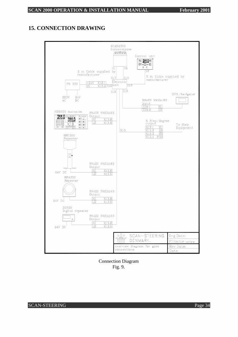
15. CONNECTION DRAWING
Connection Diagram
Fig. 9.

SCAN 2000 OPERATION & INSTALLATION MANUAL February 2001
SCAN-STEERING Page 35
16. INSTALLATION DRAWINGS
Fig. 10.

SCAN 2000 OPERATION & INSTALLATION MANUAL February 2001
SCAN-STEERING Page 36

SCAN 2000 OPERATION & INSTALLATION MANUAL February 2001
SCAN-STEERING Page 37
X1 - X17 Cable Description
17. CABLE DIAGRAMS (3 included cables)

SCAN 2000 OPERATION & INSTALLATION MANUAL February 2001
SCAN-STEERING Page 38
X2 - X19 Cable Description
SCAN 2000 OPERATION & INSTALLATION MANUAL February 2001
SCAN-STEERING Page 39
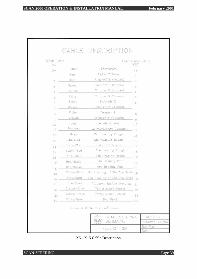
X5 - X15 Cable Description

SCAN 2000 OPERATION & INSTALLATION MANUAL February 2001
SCAN-STEERING Page 40
18. SPAREPART LIST ITM Description Part Number
1 SCAN2000 Main compass 2000-100
2 SCAN2000 Electronic unit 2000-200
3 SCAN2000 Control unit 2000-300
4 Gyroscope 2000-100-001
5 Accelerometer 2000-100-002
6 Lamps for Main compass 2000-100-003
7 Cable X1 - X15 2000-100-004
8 Cable X5 - X17 2000-100-005
9 Shock 2000-100-006
11 Power supply PCB 2000-200-001
12 Gyro Moto supply PCB 2000-200-002
13 Control PCB 2000-200-003
14 Timer PCB 2000-200-004
15 Speed input PCB 2000-200-005
16 Azimuth/Horizontal channel stabilization amplifier PCB 2000-200-006
17 Heading transformer PCB 2000-200-007
18 NMEA Code PCB 2000-200-008
19 Step voltage generation PCB 2000-200-009
20 Cable X19 - X2 2000-200-010
21 X12 Power Plug 2000-200-011
22 X13 Step / NMEA Output Plug 2000-200-012
23 X16 GPS Input Plug 2000-200-013
24 SSE2200 V1.1 PCB 2000-300-001
25 SSE2300 V1.2 PCB 2000-300-002

SCAN 2000 OPERATION & INSTALLATION MANUAL February 2001
SCAN-STEERING Page 41
19. OPTIONAL NMEA DISTRIBUTION BOX

SCAN 2000 OPERATION & INSTALLATION MANUAL February 2001
SCAN-STEERING Page 42
20. CONNECTING SCAN 2000 TO EXCISTING HE 550/600 AUTOPILOT
When connecting the Scan 2000 Gyrocompass to the HE 550/600 autopilot, the connection
must be done using the step output from the gyrocompass.
The Connections are :
Scan-2000 HE-550/600
Plug X13
1 - 68
2 - 69
3 - 70
4 - 71
WARNING : On the ANALOG PCB of the HE 550/600 Autopilot there is a plug (P1B)
Check if there is a short between pin8 and pin12, if this short exists it must be removed!. This
is very important, in case the short is not removed, it could cause permanent damage to both
Autopilot and Gyrocompass.
Also on the Analog PCB of the HE 550/600 there is a socket mounted with 3 resistors and 3
shorts, in a plug. This plug is for POS/NEG step reference, it must be the positive type
(fig. 2.1)
On the CPU PCB inside the HE 550/600 autopilot there is a EPROM containing the program
for the pilot, this EPROM must be of type VSD1 v10.

SCAN 2000 OPERATION & INSTALLATION MANUAL February 2001
SCAN-STEERING Page 43
How to get the correct gyro course into the HE 550/600 when connected and both gyro and
autopilot is started :
- Key in the course of the gyro on the pilots keypad.
- Press ENTER on the pilot.
- Now press the GYRO button and hold it for about 6 sec.
Now the gyro-course will be transmitted to the COURSE display of the pilot.