savannah river site high level waste salt disposition ... river site high level waste salt...
TRANSCRIPT

Savannah River Site
High Level Waste Salt DispositionSystems Engineering Team
Final Report (U)
WSRC-RP-98-00170Revision: 0
October 29, 1998
Copy #: ______

High Level Waste Salt Disposition WSRC-RP-98-00170Systems Engineering Team Revision: 0Final Report Page 2 of 135
HLW Salt Disposition Systems Engineering TeamFinal Report
Approved By: ________________________________ _______________S. F. Piccolo, HLW Salt Disposition DateSystems Engineering Team Leader

High Level Waste Salt Disposition WSRC-RP-98-00170Systems Engineering Team Revision: 0Final Report Page 3 of 135
DISCLAIMER
This report was prepared by Westinghouse Savannah River Company (WSRC) for theUnited States Department of Energy under Contract No. DEA-AC09-96SR18500 and isan account of work performed under that contract. Neither the United States Departmentof Energy, nor WSRC, nor any of their employees makes any warranty, expressed orimplied, or assumes any legal liability or responsibility for the accuracy, completeness, orusefulness of any information, apparatus, or product or process disclosed herein orrepresents that its use will not infringe privately owned rights. Reference herein to anyspecific commercial product, process or service by trademark, name, manufacturer orotherwise does not necessarily constitute or imply endorsement, recommendation, orfavoring of same by WSRC or by the United States Government or any agency thereof.The views and opinions or the authors expressed herein do not necessarily state or reflectthose of the United States Government or any agency thereof.

High Level Waste Salt Disposition WSRC-RP-98-00170Systems Engineering Team Revision: 0Final Report Page 4 of 135
REVISION SUMMARY
Rev. No. Rev. Date Affected Sections Description of Revision
0 10/29/98 N/A Initial Draft
High Level Waste Salt Disposition WSRC-RP-98-00170Systems Engineering Team Revision: 0Final Report Page 5 of 135
Abstract
This report describes the process used and results obtained by the High Level Waste(HLW) Salt Disposition Systems Engineering Team (Team) to select a primary andbackup alternative salt disposition method for the Savannah River Site (SRS). TheExecutive Summary located in Section 1.0 provides a high level summary of the selectionprocess. The Team activities leading to the selection of the recommended alternatives aredescribed in the remaining sections of this report. The selection of an alternative saltdisposition technology is necessary as the existing In Tank Precipitation (ITP) processcannot simultaneously meet the HLW flow sheet production and safety requirements. Tofulfill the mission need SRS HLW salt must be immobilized for final disposition insupport of environmental protection, safety, and current and planned missions. The Teamselected Small Tank Tetraphenylborate (TPB) Precipitation as the recommendedalternative to the currently configured In Tank Precipitation (ITP) process for HLW saltdisposition, with Crystalline Silicotitanate (CST) Non-Elutable Ion Exchange as thebackup technology.

High Level Waste Salt Disposition WSRC-RP-98-00170Systems Engineering Team Revision: 0Final Report Page 6 of 135
Table of Contents
1.0 Executive Summary................................................................................................ 101.1 Charter............................................................................................................ 101.2 Selection......................................................................................................... 111.3 Systems Engineering....................................................................................... 141.4 Team Members and External Input ................................................................. 151.5 Risk Management ........................................................................................... 151.6 Flowsheet ....................................................................................................... 161.7 Cost ................................................................................................................ 171.8 Deliverables.................................................................................................... 18
2.0 Introduction and Purpose........................................................................................ 192.1 Background .................................................................................................... 202.2 High Level Waste System Overview............................................................... 212.3 Team Activities............................................................................................... 25
3.0 Systems Engineering Process................................................................................... 274.0 Technology Identification....................................................................................... 30
4.1 Technology Search Phase................................................................................ 304.2 Technology Categories ................................................................................... 334.3 Initial List Alternatives ................................................................................... 334.4 Process Description of the Four Short List Alternatives................................... 374.5 Technologies Not Carried Forward to the Short List ....................................... 39
5.0 Risk Management.................................................................................................... 415.1 Identification Phase......................................................................................... 415.2 Investigation Phase ......................................................................................... 435.3 Selection Phase ............................................................................................... 44
6.0 Flowsheet Development .......................................................................................... 486.1 Identification Phase......................................................................................... 486.2 Investigation Phase ......................................................................................... 486.2 Selection Phase ............................................................................................... 49
7.0 Cost/Schedule and Systems Integration ................................................................... 557.1 Evolution of Cost Estimates ............................................................................ 557.2 Technical Integration of the Alternatives into the High Level Waste System... 597.3 Total Project Cost and Contingency Analysis.................................................. 627.4 Schedule ......................................................................................................... 677.5 Cash Flow....................................................................................................... 737.6 Operation and Maintenance Cost .................................................................... 787.7 Decontamination and Decommissioning (D&D) Cost ..................................... 797.8 Life Cycle Cost............................................................................................... 807.9 Production Model Analysis ............................................................................. 807.10 HLW System LCC.......................................................................................... 837.11 Application of Contingency to Life Cycle Cost ............................................... 87

High Level Waste Salt Disposition WSRC-RP-98-00170Systems Engineering Team Revision: 0Final Report Page 7 of 135
8.0 Uncertainties .......................................................................................................... 919.0 Selection............................................................................................................... 101
9.1 Initial List Selection Process ......................................................................... 1019.2 Short List Selection Process .......................................................................... 1029.3 Selection of the Preferred Alternatives .......................................................... 115
10.0 Recommendations ................................................................................................. 13111.0 Acronyms.............................................................................................................. 13212.0 References............................................................................................................. 134Enclosures...................................................................................................................... 135
High Level Waste Salt Disposition WSRC-RP-98-00170Systems Engineering Team Revision: 0Final Report Page 8 of 135
Figures
Figure 2-1: HLW System Major Interfaces.................................................................... 24Figure 3-1: Mission and Top-Level Functions ............................................................... 28Figure 4-1: Salt Disposition Technologies .................................................................... 37Figure 6-1: Example of a Work Scope Task Definition Document................................. 51Figure 6-2: CST Non-Elutable Ion Exchange ................................................................ 52Figure 6-3: Example of Engineering Integrated Commitment Matrix............................. 53Figure 7-1: Scope and Cost Integration Method............................................................. 58Figure 7-2: Monte Carlo Analysis for Caustic Side Solvent Extraction .......................... 65Figure 7-3: Caustic Side Solvent Extraction Summary Schedule ................................... 69Figure 7-4: CST Non-Elutable Ion Exchange Summary Schedule ................................. 70Figure 7-5: Direct Disposal in Grout Summary Schedule .............................................. 71Figure 7-6: Small Tank TPB Precipitation Summary Schedule...................................... 72Figure 9-1: Selection Process Summary....................................................................... 101Figure 9-2: Short List Selection Process ...................................................................... 103Figure 9-3: Caustic Side Solvent Extraction ................................................................ 108Figure 9-4: CST Non-Elutable Ion Exchange .............................................................. 110Figure 9-5: Direct Disposal in Grout ........................................................................... 112Figure 9-6: Small Tank TPB Precipitation................................................................... 114Figure 9-7: Quantitative Comparison of Alternatives................................................... 116Figure 9-8: Quantitative Comparison of Alternatives With Uncertainties..................... 117Figure 9-9: Schedule Uncertainty for the Short List Alternatives ................................. 118

High Level Waste Salt Disposition WSRC-RP-98-00170Systems Engineering Team Revision: 0Final Report Page 9 of 135
Tables
Table 1-1: Key Selection Parameters............................................................................. 12Table 4-1: DOE Complex Technology Review Comparison.......................................... 32Table 6-1: Field Confirmation Trips .............................................................................. 49Table 7-1: Preliminary Life Cycle Cost Estimate Summary........................................... 56Table 7-2: Flowsheet Throughputs ................................................................................ 62Table 7-3: TPC Estimates.............................................................................................. 63Table 7-4: Total Estimated Cost .................................................................................... 66Table 7-5: Other Project Costs ...................................................................................... 67Table 7-6: Caustic Side Solvent Extraction Summary Cash Flow .................................. 74Table 7-7: CST Non-Elutable Ion Exchange Summary Cash Flow ................................ 75Table 7-8: Direct Disposal in Grout Summary Cash Flow ............................................. 76Table 7-9: Small Tank TPB Precipitation Summary Cash Flow..................................... 77Table 7-10: Average Yearly O&M Costs....................................................................... 79Table 7-11: D&D Costs................................................................................................. 80Table 7-12: Key Results Summary Information............................................................. 82Table 7-13: HLW Total System LCC (Escalated Dollars).............................................. 84Table 7-14: HLW Total System LCC (Constant FY99 Dollars) ..................................... 85Table 7-15: HLW Total System LCC (Discounted Dollars)........................................... 86Table 7-16: Contingency Percentage (50% Probability Point) ....................................... 87Table 7-17: Total LCC Point Estimates ......................................................................... 88Table 7-18: Upper/Lower Box Limits............................................................................ 90Table 8-1: Quantified Uncertainties............................................................................... 92Table 9-1: Qualitative Crosscheck Matrix ................................................................... 121Table 9-2: Interfaces with Salt Disposition Process ..................................................... 124Table 9-3: Alternative Attribute Ranking .................................................................... 128

High Level Waste Salt Disposition WSRC-RP-98-00170Systems Engineering Team Revision: 0Final Report Page 10 of 135
1.0 Executive Summary
The purpose of this section is to provide a high level summary of the activities leading tothe selection of the recommended alternatives to the ITP process. This summarydescribes the HLW mission, the ITP process suspension, the Team Charter, the selectionprocess, and the recommendation.
1.1 Charter
The Savannah River Site (SRS) Site Treatment Plan (STP) and Federal FacilitiesAgreement (FFA) call for closing the HLW Tanks through vitrification of boththe long-lived and short-lived radioisotopes in the Defense Waste ProcessingFacility (DWPF) in preparation for transport to the national high level wasterepository. To make this program economically feasible, it is necessary to limitthe volume of HLW glass produced by removing much of the non-radioactivesalts and incidental wastes for disposal as saltstone. The ITP facility was designedand constructed to separate the cesium isotopes from the non-radioactive salts sothe decontaminated salts could be disposed in a grouted wasteform at theSaltstone facility at SRS.
The ITP process was successfully piloted both on a moderate and full-scale basiswith actual SRS waste in the 1980s. During the facility radioactive startup, higherthan predicted benzene releases were observed. Additional laboratory and facilitytests were initiated to further investigate process chemistry issues. In January1998, conclusions were drawn from the test program that the benzene releaserates associated with facility operation could exceed the capability of the currentplant hardware/systems. On January 22, 1998, Westinghouse Savannah RiverCompany (WSRC) informed DOE that ITP chemistry testing demonstrated thatthe present system configuration could not cost-effectively meet the safety andproduction requirements for the ITP facility and recommended that a study ofalternatives to the current system configuration be conducted by a systemsengineering team.
On February 6, 1998, the Assistant Secretary for Environmental Managementapproved a DOE-Savannah River (DOE-SR) plan of action to suspend startup-related activities and undertake a systems engineering study of alternatives to ITP.On February 20, 1998, DOE-SR concurred with the WSRC evaluation of the ITPchemistry data, instructed WSRC to suspend ITP startup preparations, anddirected WSRC to perform an evaluation of alternatives to the current systemconfiguration for HLW salt removal, treatment, and disposal.

High Level Waste Salt Disposition WSRC-RP-98-00170Systems Engineering Team Revision: 0Final Report Page 11 of 135
On March 13, 1998, the WSRC High Level Waste Management Divisionchartered the Team to systematically develop and recommend an alternativemethod and/or technology for disposition of HLW Salt. The selected Teammembers were approved by DOE on March 31, 1998.
1.2 Selection
At the start of the selection process, the Team had concluded that the four ShortList alternatives were implementable, and that project and life cycle cost shouldbe the prime driver in the selection process. As overall cost and uncertainty datawere developed, it was recognized that costs were similar enough to not be theprime discretionary driver in selection, so the Team considered technical maturity,risk management, safety and Team member expertise in the selection.
The Team’s recommended alternative is Small Tank TPB Precipitation. Althoughit did not have the lowest life cycle cost, it has the lowest project cost, the highestscientific maturity, the most-manageable risks, and is judged to have the highestlikelihood of success because the open issues for this technology affectmechanical sizing more than chemical processing or chemistry solutions. Theissues raised regarding TPB in the ITP process have been definitively addressedin the pre-conceptual design to answer concerns regarding benzene flammability.The process includes positive pressure nitrogen inerting and secondaryconfinement of the process vessels. In addition, the stainless steel small tankdesign, with its shorter processing time, minimizes the product stability issueswhile achieving desired decontamination.
As a backup technology, the Team selected CST Non-Elutable Ion Exchange. Aswell as having a lower project cost and life cycle cost than solvent extraction, itsscientific maturity is higher and it has greater opportunity for recovery fromprocess performance problems. Solvent Extraction offers benefits because of itsdesirable interface with DWPF, better inherent safety and greatest potential forproduction improvements through further R&D and value added engineeringefforts. However, with the Team’s Charter requirement for “assured success”,CST was the preferred backup.

High Level Waste Salt Disposition WSRC-RP-98-00170Systems Engineering Team Revision: 0Final Report Page 12 of 135
Some of the key selection parameters are listed below in Table 1-1:
Table 1-1: Key Selection Parameters
Selection Parameter TPB CST
Project Capital Cost (TEC), includingcontingency $M
692 768
Other Project Costs (OPC), includingcontingency $M
378 418
Life Cycle Cost Point Estimate, includingcontingency $M (This includes TEC and OPC)
3,453 2,877
Baseline Date for Radioactive Operation May 2006 March 2007Date for Radioactive Operation, includinguncertainty
May 2010 January2012
Baseline Date for Tank Emptying Oct. 2020 April 2019Date for Tank Emptying, including uncertainty July 2025 January
2025
The Team evaluation was based on an exhaustive review of potential technologiesat the pre-conceptual level for disposition of salt contained in the SRS HLWTanks. Technologies that appeared to have a significant chance of success in thisapplication were developed to the flowsheet level and were studied with visits tofacilities and laboratories involved in their development and use. Then, thehandful of technologies that emerged as leading contenders were subjected to amore rigorous flowsheet and layout analysis and were targeted in specificResearch and Development programs to more precisely understand their strengthsand weaknesses. The preferred and backup alternatives finally selected aretechnically sound and have been shown to be capable of successfulimplementation on the required schedule .
Additionally, the Team focused a great deal of attention on the inherent safety ofthe proposed technologies. During the early phases of Team activities, inherenthuman and environmental safety were key criteria used in distinguishing amongalternatives. In the final stages, a hazards evaluation was performed of the finalcandidates. The preferred choice has minimal inherent hazards and has a clearsafety strategy to address the residual hazards.
Finally, technology alternatives under consideration were subjected toincreasingly detailed cost analyses to support pre-conceptual level estimates. Theanalyses addressed project cost, operating cost, and total life cycle cost, takinginto account the identified uncertainties for each technology. For the final

High Level Waste Salt Disposition WSRC-RP-98-00170Systems Engineering Team Revision: 0Final Report Page 13 of 135
candidates, cost estimates included contingency analysis. The final choice of apreferred alternative was based on cost, with identified residual uncertaintiestaken into account, technical maturity, risk management, safety, the professionaljudgement of the Team, historical experience, and SRS and DOE Complex needs.
In its deliberations, the Team was impressed with the technical benefits of theDirect Disposal in Grout alternative. This alternative clearly had the lowesttechnical risk of the Short List alternatives. The grouting process is widely usedfor immobilization of radioactive waste. While a new formulation of grout maybe necessary to optimize the wasteform for this particular mixture, it isnoteworthy that the existing Saltstone formulation which contains very similarchemical components, appears to give satisfactory results as demonstrated in theperformance assessment. The process itself has a lengthy track record for wastecontaining much higher levels of radioactivity than would be experienced at SRS.
The project cost, including technical uncertainties is lower than that of any of theother alternatives under consideration. The baseline schedules, withoutuncertainties, to place the facility into operation and to empty the SRS HLWTanks are shortest for this alternative.
The grouting process provides a high level of protection for the health and safetyof the public and the environment. The reduction in cesium 137 loading of theDWPF canisters reduces the heat load on the HLW repository over the first fewhundred years an impact recognized by the NRC as assisting in limiting thepotential migration of HLW from the repository. Even with the loading of cesium137 in the grouted material, the final wasteform left at SRS is only at 5% of theClass C limit. Additionally, even if the cesium 137 were to leach from the grout,cesium does not migrate to any great extent through the SRS type soil. Finally,the half-life of cesium 137 is thirty years. By about the time the grouting processis completed, half of the cesium resulting from SRS reactor operation existing atthe time of K-Reactor shutdown will have decayed. After three hundred years, ashort time compared to the migration speed of the cesium, over 99.9% of thecesium will have decayed. The grouted cesium will present no hazard to peopleor the environment after it has been placed in the grout matrix.
In spite of these advantages, the Team felt the Direct Disposal in Grout could notbe selected as either the primary or backup recommendation. The reason for thisis the non-technical programmatic risks. The recommended alternative must havea sure path to operation by 2010 and the closure of the SRS HLW Tanks inaccordance with the FFA and STP commitments. The Team knows of nomitigation strategy that would assure that the facility could be commissioned,NRC, SCDHEC, and EPA approvals could be obtained, and likely court casesresolved in a manner compatible with this schedule. In addition, tests

High Level Waste Salt Disposition WSRC-RP-98-00170Systems Engineering Team Revision: 0Final Report Page 14 of 135
demonstrated that the cesium could leach. Although acceptably passing theperformance assessment requirements, the Team felt that public acceptance wouldbe more difficult than originally anticipated. The three sequential risks ofregulatory approval, political approval, and judicial approval, all of which havebeen seen in similar instances, could not be guaranteed to be resolved on thenecessary schedule with any mitigation strategy the Team could devise. If such astrategy were available, Direct Disposal in Grout would have been the Team’srecommendation.
It should also be noted that Solvent Extraction ranked favorably by the Teamwhen compared to CST Non-Elutable Ion Exchange as a backup selection. Therelative immaturity of the calixarene crown ether extractant was the majordeciding factor. Positive attributes associated with this technology wereoperational, mission and operating schedule flexibility. However, Teamjudgement was that CST could be more readily implemented today and solventextraction would require approximately two years of favorable scientificdevelopment to influence the decision.
1.3 Systems Engineering
The Systems Engineering approach was both required by the Charter andrecognized by the Team as the most appropriate tool for accomplishing itsassigned task.
The Systems Engineering Management Plan (SEMP) provides a high leveldescription of the methodology, tools, deliverables, and schedules required toimplement the systems engineering approach for Team activities. The InitialDesign Input provides the Team Mission Need and Problem Statement and thehighest level functions and requirements applicable to the eventual preferredalternative(s). The SEMP is the parent document to the position papers anddesktop procedures written by the Team to control its activities in choosing apreferred alternative(s). The Initial Design Input provides the basis for criteriadeveloped to distinguish among potential technologies for recommendation.
The Team activities were pursued in three distinct phases referred to as theIdentification, Investigation and Selection Phases. The Identification Phaseresulted in the “Initial List” of eighteen alternatives. The Investigation Phaseresulted in the “Short List” of four alternatives. The Selection Phase resulted inSmall Tank TPB Precipitation as the primary alternative and CST Non-ElutableIon Exchange as the backup alternative.

High Level Waste Salt Disposition WSRC-RP-98-00170Systems Engineering Team Revision: 0Final Report Page 15 of 135
The Team implementation of the SE process was predicated on a consensusphilosophy. If consensus was not reached by the Team members during anydecision or phase of Team activities, a formal Dissenting Opinion vehicle existedto document the opposing view(s). The Team procedure for this process requiresthat all Dissenting Opinions be made part of the Final Report. There were threeDissenting Opinions generated during the Team’s activities and are listed belowby title.
DO98001: Solvent Extraction O&M Duration - Section 7.0
DO98002: Solvent Extraction Contingency Value - Section 7.0
DO98003: Backup Alternative Technology Selection – Section 9.0
All the Team members concurred that DO98001 and DO98002 had no effect onthe recommendations. The Team did not achieve consensus on the backupalternative selection. The response to the dissenting opinion was accepted by allTeam members
1.4 Team Members and External Input
Team members were chosen to provide expertise in Systems Engineering, ProcessEngineering, Operations, Waste Processing, Science, Safety and RegulatoryEngineering, Chemistry, and Chemical Processes. Members were also chosen toprovide viewpoints from other DOE Complex facilities with large radioactivewaste disposal programs, international radioactive waste disposal programs, theNational Labs, industry, and academia. Significant WSRC engineering resourceswere dedicated to and managed by the Team, as was an administrative supportstaff. Research and Development support and management was provided by theSavannah River Technology Center (SRTC). Additional Research andDevelopment (R&D) support was provided by the Oak Ridge and ArgonneNational Laboratories and several universities (Texas A&M University,University of South Carolina, and Purdue University).
1.5 Risk Management
Throughout the process, risk identification and management was a commontheme of Team activities.
During the Identification Phase, risk identification and management wasimplemented by conducting a coarse screening of technical categories and thealternatives within each category. The technical categories were evaluatedagainst two broad risk areas, i.e., Technical Maturity and a Reasonable Chance of

High Level Waste Salt Disposition WSRC-RP-98-00170Systems Engineering Team Revision: 0Final Report Page 16 of 135
Deployment. If the Team lacked sufficient knowledge to assess the category, thenit was accepted for screening of the individual alternatives.
The Team then proceeded to screen and rank the individual alternatives withineach technical category. The Safety, Schedule, Cost, Science, and Processscreening criteria were derived from the Initial Design Input. Alternatives failingany one of these screening criteria were considered as having unacceptable riskand were dropped from further consideration. The result of the IdentificationPhase was an Initial List of eighteen accepted alternatives.
During the Investigation Phase, the Team developed additional information on theInitial List of alternatives. This facilitated a more rigorous Preliminary RiskAssessment of the alternatives. A detailed checklist of risk screening questions inthe areas of Technology, Interfaces, Safety, Design, Resources/Conditions,Cost/Schedule, Procurement, and Regulatory/Environmental was developed andapplied to each of the alternatives. Statements of risk applicable to each of thealternatives were documented, and relative estimates of probability andconsequence for these risks were generated. Significant risks were assigned risk-handling strategies. The quantified risks, along with qualitative information, wereused in the selection from the Initial List to a Short List of four alternatives.
In the Selection Phase the Team reviewed risks identified in previous phases of itsactivities for applicability. National and international experts and stakeholderswere convened for a five-day period of risk assessment of both technical andprogrammatic risks associated with the Short List alternatives. From theseactivities, the Team developed a consolidated list of risks to be considered duringthe Selection Phase.
The risks were reviewed and quantified as to potential cost and schedule impacts(uncertainties) to the implementation of the alternative. After consideration of theidentified risks, the uncertainties were reviewed to see which could be consideredto fall within normal project contingency and which had to be considered inaddition to normal project contingency.
Positive as well as negative uncertainties in terms of both Cost and Scheduleimpacts were used by the Team to facilitate the final selection process.
1.6 Flowsheet
A Flowsheet Team was formed to provide process and layout information to theTeam during the pre-conceptual design process. Flowsheets were first developedas part of the Investigation Phase of pre-conceptual design. During theIdentification Phase of Team activities, the alternative technologies were

High Level Waste Salt Disposition WSRC-RP-98-00170Systems Engineering Team Revision: 0Final Report Page 17 of 135
reviewed at a very high technical level for reasonable chance of deployment.Only those that did not meet minimum requirements were eliminated. However,during the Investigation Phase, a more rigorous process was used. This processinvolved the technical development of the alternatives composing the Initial List.These efforts included the generation of flowsheets, including material balances,for the alternatives; observation of related waste management processes at WestValley, Oak Ridge, Hanford, Idaho National Engineering and EnvironmentalLaboratory (INEEL) and Sellafield (BNFL) by Team members; preliminary costand schedule evaluations; and preliminary risk/mitigation assessments.
The Selection Phase of Team activities provided the basis for the Teamrecommendation of the preferred alternative(s). The focus of this phase was todevelop, at a pre-conceptual level, the baseline cost and schedule forimplementation of each of the Short List alternatives and to evaluate the potentialimpacts of identified risks as uncertainties in project cost and schedule. The Teaminitiated a number of activities during the Selection Phase to support theevaluation of these alternatives. These activities included continuing refinementof the flowsheets and models to provide preliminary equipment sizing, facilitylayout/siting and material/energy balances; specific Research and Developmentactivities at SRTC, Oak Ridge National Laboratory (ORNL), Argonne NationalLaboratory (ANL) and the University of South Carolina, and Purdue and TexasA&M Universities on aspects key to the selection process; a hazards evaluation ofthe processes to better define potential safety concerns; and detailed pre-conceptual cost and schedule estimates for the Total Project and Life Cycle Costsof the alternatives.
The Team recognized commitments existed to close the SRS HLW Tanks by theFFA/STP schedule and to begin emptying the HLW Tanks by 2010 to avoid“waterlogging” in the Tank Farm. The mission requires that the recommendedalternative(s) have a high confidence of success. Therefore, the selection processhad to develop each alternative to a level that would provide a clear vision of thetechnical implementation of the alternative, identify credible risks and quantifyresulting uncertainties. The cost of resolving problems arising from the identifiedrisks was included in the Team evaluation.
1.7 Cost
The Team evaluation of cost became more detailed as the technical definition ofalternative technologies became more refined. Initially, broad estimates of costwere used to see if alternatives were credible. No alternative technologies wereeliminated on this basis. During the Investigation Phase, rough estimates wereestablished based on previous experience, but were given lower weight thantechnical and safety criteria. During the Selection Phase, more detailed pre-

High Level Waste Salt Disposition WSRC-RP-98-00170Systems Engineering Team Revision: 0Final Report Page 18 of 135
conceptual estimates were established for the Short List alternatives. TEC, OPCand LCC estimates were produced, and contingency analyses were performedusing Monte Carlo techniques to produce contingency estimates. Technical andprogrammatic risks carried forward in the selection process were then evaluatedfor impact on cost and schedule. The estimated cost of addressing the uncertaintyand the cost of schedule change or delay was applied to the LCC estimates whereit was considered not to be within the already calculated LCC contingency. Thisvalue reflected the potential total cost of the project, including the cost to addressproblems arising from the identified project risks.
1.8 Deliverables
The final deliverables defined in the Team Charter are a completed pre-conceptual design, initial cost estimate, a final report on Team activities and arecommendation on a preferred alternative(s).
The Pre-Conceptual Design Package and Facility Design Description (Chapter 1)satisfy the pre-conceptual design deliverable and are shown in Enclosures 1, 2, 4and 5.
The “Life Cycle Cost Estimate Bases, Assumptions, and Results” documentsatisfies the initial cost estimate deliverable and is shown in Enclosure 7.
This Report satisfies the final report deliverable on Team activities.
The Team recommends the use of Small Tank TPB Precipitation as the methodfor disposition of SRS high level waste salt. CST Non-Elutable Ion Exchange isrecommended as a backup technology.
Submittal of this report completes chartered Team activities.

High Level Waste Salt Disposition WSRC-RP-98-00170Systems Engineering Team Revision: 0Final Report Page 19 of 135
2.0 Introduction and Purpose
The SRS STP and FFA call for closing the HLW Tanks through vitrification of both thelong-lived and short-lived radioisotopes in DWPF in preparation for transport to thenational high level waste repository. To make this program economically feasible, it isnecessary to limit the volume of HLW glass produced by removing much of the non-radioactive salts and incidental wastes for disposal as saltstone. The ITP facility wasdesigned and constructed to separate the cesium isotopes from the non-radioactive saltsso the decontaminated salts could be disposed in a grouted wasteform at the Saltstonefacility at SRS.
The ITP process was successfully piloted both on a moderate and full-scale basis withactual SRS waste in the 1980s. During the facility radioactive startup, higher thanpredicted benzene releases were observed. Additional laboratory and facility tests wereinitiated to further investigate process chemistry issues. In January 1998, conclusionswere drawn from the test program that the benzene release rates associated with facilityoperation could exceed the capability of the current plant hardware/systems. On January22, 1998, WSRC informed DOE that ITP chemistry testing demonstrated that the presentsystem configuration could not cost-effectively meet the safety and productionrequirements for the ITP facility and recommended that a study of alternatives to thecurrent system configuration be conducted by a systems engineering team.
On February 6, 1998, the Assistant Secretary for Environmental Management approved aDOE-SR plan of action to suspend startup-related activities and undertake a systemsengineering study of alternatives to ITP. On February 20, 1998, DOE-SR concurred withthe WSRC evaluation of the ITP chemistry data, instructed WSRC to suspend ITP startuppreparations, and directed WSRC to perform an evaluation of alternatives to the currentsystem configuration for HLW salt removal, treatment, and disposal.
In March 1998, a WSRC-sponsored High Level Waste Systems Engineering Team(Team) was formed to study alternatives to the ITP processes as well as methods toenhance the current process. The multi-disciplined Team was chartered with the task of“systematically developing and recommending an alternative method and/or technology
The Charter also identified the following deliverables:
• Systems Engineering Team Selection
• System Engineering Management Plan
• Report Summarizing Activities Leading to the Initial List of Alternatives
• Report Summarizing Activities Leading to the Short List of Alternatives

High Level Waste Salt Disposition WSRC-RP-98-00170Systems Engineering Team Revision: 0Final Report Page 20 of 135
• Interim Progress Report
• Detailed Evaluation Criteria for the Short List
• Preliminary Risk Assessments
• Programmatic Risk Assessments and Mid-Course Correction
• Pre-conceptual Design and Initial Cost Estimate
• Final Report
This report constitutes the “Final Report” required by the Team Charter.
2.1 Background
High Level Waste has been produced at the Savannah River Site since 1951. Thiswaste was stored in Interim Waste Tanks. In the early 1980s, a concept wasdeveloped to no longer construct additional Interim Waste Tanks, but to processthe waste into a safer storage form, reduce risk, and ready the waste for permanentstorage. This led to an initial design concept for DWPF and an Ion ExchangeFacility.
The cost for both facilities was high, and technical uncertainties for Ion Exchangeposed too high a risk. Alternatives to the Ion Exchange Process were evaluatedand the ITP process was selected due to lower projected cost and technical risk.
The Savannah River Site currently stores 34 million gallons of HLW in InterimStorage Tanks. This activity is considered to be one of the higher risk activitieson the Site. The FFA requires removing the waste from the high level waste tanksto resolve several safety and regulatory concerns. Tanks have leaked observablequantities of waste from primary to secondary containment. Other tanks haveknown penetrations above the liquid level, although no waste has been observedto leak through these penetrations. The “old style” tanks do not meet EPAsecondary containment standards for storage of hazardous waste, (effectiveJanuary 12, 1987). The 34 million gallons of liquid waste stored in the HLWtanks are composed of 31 million gallons of “Salt” and 3 million gallons ofsludge. The Sludge process is fully operational. The ITP process was thebaseline method intended for handling Salt.
During the facility radioactive startup, higher-than-predicted benzene releaseswere observed, and a program was initiated to further investigate processchemistry issues. The program concluded that the benzene release ratesassociated with facility operation could exceed the capability of the current planthardware/systems. WSRC informed DOE that the present system configurationcould not cost-effectively meet the safety and production requirements for the ITP
High Level Waste Salt Disposition WSRC-RP-98-00170Systems Engineering Team Revision: 0Final Report Page 21 of 135
facility and recommended that a study of alternatives to the current systemconfiguration be conducted by a Systems Engineering team.
With the formation of the Team, a DOE-sponsored charter was issued to guide thesystems engineering process for determination of a preferred salt dispositiontechnology. The need for a timely decision was identified from impacts to thefollowing: Limited Tank Farm storage capacity, additional DWPF glass canisterproduction, incurred Life Cycle Cost (LCC) and prolonged environmental risk forliquid waste storage.
2.2 High Level Waste System Overview
Any new salt processing system will interface with existing facilities, and the easeor difficulty of the successful implementation of an alternative technology isgoverned by how well it will integrate into the existing HLW System.
The HLW System is a set of seven different interconnected processes (Figure 2-1)operated by the High Level Waste and Solid Waste Divisions. These processesfunction as one large treatment plant that receives, stores, and treats high levelwastes at SRS and converts these wastes into forms suitable for final disposal.The three major permitted disposal forms are borosilicate glass, planned fordisposal at a Federal Repository; saltstone grout, disposed in vaults on the SRSsite; and treated water effluent, released to the environment.
These processes currently include:
• High Level Waste Storage and Evaporation (F and H Area Tank Farms)
• Salt Processing (In Tank Precipitation and Late Wash Facilities)
• Sludge Processing (Extended Sludge Processing Facility)
• Vitrification (DWPF)
• Wastewater Treatment (Effluent Treatment Facility)
• Solidification (Saltstone Facility)
• Organic Destruction (Consolidated Incineration Facility)
F and H Area Tank Farm, Extended Sludge Processing, DWPF, EffluentTreatment Facility, Saltstone Facility, and the Consolidated Incineration Facilityare all operational. ITP Facility operations are limited to safe storage and transferof materials. The Late Wash Facility has been tested and is in a dry lay-up status.

High Level Waste Salt Disposition WSRC-RP-98-00170Systems Engineering Team Revision: 0Final Report Page 22 of 135
The mission of the HLW System is to receive and store SRS high level wastes ina safe and environmentally sound manner and to convert these wastes into formssuitable for final disposal. The planned forms are:
• borosilicate glass to be sent to a Federal Repository
• saltstone to be disposed of on site
• treated wastewater to be released to the environment. Also, the storage tanks and facilities used to process the high level waste must beleft in a state such that they can be decommissioned and closed in a cost-effectivemanner and in accordance with appropriate regulations and regulatoryagreements. All high level wastes in storage at SRS are Land Disposal Restrictions (LDR)wastes, which are prohibited from permanent storage. Since the plannedprocessing of these wastes will require considerable time and therefore continuedstorage of the waste, DOE has entered into a compliance agreement with the EPAand SCDHEC. This compliance agreement is implemented through the STP,which requires processing of all the high level waste at SRS according to aschedule negotiated between the parties.
Figure 2-1 schematically illustrates the routine flow of wastes through the HLWSystem. The various processes within the system and external processes areshown in rectangles. The numbered streams identified in italics are the interfacestreams between the various processes. The discussion below represents theHLW System configuration as of January 1998. Incoming high level wastes are received into HLW Storage and Evaporation (Fand H Area Tank Farms) (Stream 1). The function of HLW Storage andEvaporation is to safely concentrate and to store these wastes until downstreamprocesses are available for further processing. The decontaminated liquid fromthe evaporators are sent to Wastewater Treatment (ETF) (Stream 13). The insoluble sludges that settle to the bottom of waste receipt tanks in HLWStorage and Evaporation are slurried using hydraulic slurrying techniques andsent to Extended Sludge Processing (ESP) (Stream 2). In ESP, sludges high inaluminum are processed to remove some of the insoluble aluminum compounds.All sludges, including those that have been processed to remove aluminum, arewashed with water to reduce their soluble salt content. The spent washwater fromthis process is sent back to the HLW Storage and Evaporation (Stream 3). Thewashed sludge is sent to Vitrification (DWPF) for feed pretreatment andvitrification (Stream 4).

High Level Waste Salt Disposition WSRC-RP-98-00170Systems Engineering Team Revision: 0Final Report Page 23 of 135
Saltcake is redissolved using hydraulic slurrying techniques similar to sludgeslurrying. As currently designed, the salt solutions from this operation, and othersalt solutions from HLW Storage and Evaporation, were intended for feed to SaltProcessing (Stream 5). In ITP, the salt solution would be processed to removeradionuclides, which are concentrated into an organic precipitate. Thedecontaminated filtrate would then be sent to Tank 50. A concentrated organicprecipitate, containing most of the radionuclides, is produced by the process. Thisprecipitate is washed with water to remove soluble salts. However, some solublecorrosion inhibitors that interfere with DWPF processing must be left in theprecipitate after washing because the precipitate is stored in carbon steel tanks,which are susceptible to corrosive attack by uninhibited precipitate wastes. The precipitate is transferred to Late Wash for further washing in stainless steeltanks to reduce the level of soluble corrosion inhibitors to acceptable levels forthe DWPF process (Stream 7). The washwater from this process is returned toITP to be reused in the ITP process (Stream 8). The washed precipitate from Late Wash is then sent to the DWPF vitrificationbuilding (221-S). In the vitrification building, the precipitate is catalyticallydecomposed and separated into two streams: a mildly contaminated organicstream and an aqueous stream containing virtually all of the radionuclides. Themildly contaminated organics are stored at DWPF and eventually transferred toOrganic Destruction (CIF) (Stream 11). The aqueous stream is combined with thewashed sludge from ESP, which has undergone further processing and themixture vitrified. The washed sludge from ESP (Stream 4) is chemically adjusted in the DWPF toprepare the sludge for feed to the glass melter. As part of this process, mercury isstripped out, purified, and sent to mercury receivers (Stream 12). The aqueousproduct from organic decomposition is added to the chemically adjusted sludge.The mixture is then combined with glass frit and sent to the glass melter. Theglass melter drives off the water and melts the wastes into a borosilicate glassmatrix, which is poured into a canister. The canistered glass wasteform is sent tosite interim storage, and will eventually be disposed of in a Federal Repository(Stream 9). The water vapor driven off from the melter along with other aqueous streamsgenerated throughout the DWPF vitrification building is recycled to HLW Storageand Evaporation for processing (Stream 10). Overheads from the HLW Storage and Evaporation evaporators are combinedwith overheads from evaporators in the F and H Area Separations processes and

High Level Waste Salt Disposition WSRC-RP-98-00170Systems Engineering Team Revision: 0Final Report Page 24 of 135
other low-level streams from various waste generators. This mixture of low-levelwastes is sent to the ETF (Stream 13). In the ETF, these low-level wastes are decontaminated by a series of cleaningprocesses. The decontaminated water effluent is sent to the H Area outfall andeventually flows to local creeks and the Savannah River (Stream 14). Thecontaminants removed from the water are concentrated and sent to Tank 50(Stream 15). In Tank 50, the concentrate from the ETF is combined with the decontaminatedfiltrate from the ITP and sent to Saltstone (Stream 6). In the Saltstone Facility,the liquid waste is combined with cement formers and pumped as a wet grout to avault (Stream 16). In the vault, the cement formers hydrate and cure, forming asaltstone monolith. The Saltstone Facility vaults will eventually be closed as alandfill
WasteGeneration
Destinations
FinalTreatment
Outfall
WasteGenerators
SaltstoneVitrification
(DWPF)
Extended SludgeProcessing
(ESP)
SaltProcessing
(ITP)
OrganicDestruction
(CIF)
WastewaterTreatment
(ETF)
Landfill Repository
Storage& Evaporation
Pretreatment
1. Incoming Wastes
13. Evaporatoroverheads& other low-levelstreams
5. Salt solution
2. Sludge 3. ESP SpentWashwater
15. ETFconcentrate 7. Precipitate
8. Late WashSpent Wash-water
4. WashedSludge
10. DWPF Recycle
9. Canistered GlassWasteform
11. RecoveredOrganic
Low-Level Aqueous Waste Treatment
High-Level Waste Treatment
MercuryReceivers
14. Treated Effluent 16. Wet Grout 12. Recovered Mercury
6. SaltstoneFeed
Tank 50
Late Wash
HLW Storage& Evaporation(F and H Tank
Farms)
Figure 2-1: HLW System Major Interfaces

High Level Waste Salt Disposition WSRC-RP-98-00170Systems Engineering Team Revision: 0Final Report Page 25 of 135
2.3 Team Activities
The Team was formed with the following members, representing national labs,academia, waste processing, science and technology, operations, process chemicalengineering, systems engineering, and integrated safety management.
NAME AREA OF CONTRIBUTION
Steve Piccolo Team LeaderGary Abell Systems EngineeringKen Rueter Process EngineeringJeff Barnes OperationsPeter Hudson Waste ProcessLucien Papouchado ScienceEd Murphy Safety and Regulatory EngineeringJack Watson ScienceEd Cussler ChemicalGene Kosiancic Chemical Process
The Team was chartered to recommend a technology for the salt dispositionprocess. In the Identification Phase, the Team collected input on diverse possibletechnologies from around the DOE Complex and the world, and completed aninitial screening process to develop the best combination of alternatives thatwould be further evaluated. This resulted in the Initial List of eighteen processingalternatives.
In the Investigation Phase, the Initial List alternatives were evaluated by the Teamto determine the probability of success for the individual alternatives along withthe identification of preliminary risks for each process. Based on this evaluationthe Team selected the Short List of four alternatives. This process has beenindependently reviewed by the WSRC Review Panel, SRS Citizen’s AdvisoryBoard (CAB), DOE-SR, and DOE Headquarters Independent Evaluation (DOE-HQ IPE) Team. Each of these reviews supported the four selected alternatives astechnically workable, capable of being implemented in the field and asrepresenting the most promising alternatives to be included in the final selectionprocess.

High Level Waste Salt Disposition WSRC-RP-98-00170Systems Engineering Team Revision: 0Final Report Page 26 of 135
The purpose of the Selection Phase was to analyze the four alternatives at a moredetailed level and recommend the preferred alternative(s) for salt disposition.This process included:
• Identifying and completing R&D activities that would minimize the level ofuncertainty associated with each process that had been identified in theInvestigation Phase
• Improving the alternative flowsheet interfaces with HLW System interfaces
• Defining the processing plant preliminary specifications (equipment size,bounding feed cases, facility layout, siting, etc.)
• Developing the preliminary construction/project/operation schedule
• Developing both the Salt Disposition Facility TPC and Life Cycle Costestimates including respective contingencies
• Identifying, evaluating and quantifying the uncertainties for each process interms of potential cost and schedule impact
• Evaluating the qualitative and quantitative information to select the preferredalternative(s)
High Level Waste Salt Disposition WSRC-RP-98-00170Systems Engineering Team Revision: 0Final Report Page 27 of 135
3.0 Systems Engineering Process
The purpose of this section is to describe the structured process the Team used toobjectively and efficiently complete its chartered activities. The process provided stepsto develop the relevant information and activities needed for Team decisions during thecourse of the pre-conceptual phase.
The Team commenced its chartered activities utilizing a structured Systems Engineering(SE) process. The process was effectively applied to identify, investigate, and select thepreferred alternative. The SE approach is instrumental in managing large and technicallycomplex projects and is recognized by both the DOE and DNFSB as an effectivemethodology for project development. DOE Order 430.1 (Life Cycle Asset ManagementLCAM) and the associated Good Practice Guides outline the principles and practices ofSystems Engineering.
The Team developed and approved a Systems Engineering Management Plan (SEMP) atthe beginning of the pre-conceptual activities in order to document the SE activities,resources, and tools that the Team would apply. The principles and practices identified inthe SEMP were implemented by the Team. Procedures, position papers, and resultsreports were developed to document the structured controls, inputs, support resourcesneeded, and outputs obtained during the Teams activities.
The SE process is a “top down” approach and requires the identification of appropriatepersonnel and resources to perform mission definitions and analysis, functions andrequirements analysis, alternative evaluation, selection, validation, and verification. Inaddition, the disciplined application of risk management, interface control, technicalplanning and integration to successfully execute the work activities are required to satisfythe SE process.
The structured process was applied in the three phases of the pre-conceptual activities.These phases are referred to as the Identification, Investigation, and Selection phases.During the initial phase, referred to as “identification”, the Team’s application of theprocess resulted in several outputs. These included the mission analysis and definition,development of necessary and sufficient functions and requirements that any alternativesolution must satisfy, and the identification and initial screening of potential solutions(alternatives).
The functions developed defined “what” the selected alternative must do to fulfill themission. The associated requirements identified specify “how well” the functions mustbe performed.

High Level Waste Salt Disposition WSRC-RP-98-00170Systems Engineering Team Revision: 0Final Report Page 28 of 135
The mission and supporting top-level functions, which must be satisfied by the preferredalternative(s), are identified in Figure 3-1 and defined in the Initial Design Input.
Safely and costeffectively process saltfrom SRS HLW tanks
to a final permittedwaste form(s)
Receive SRS wastestreams
Protect personnel andthe environment fromhazards and releases
of waste and pollution
Store existing andreceived waste
streams
Treat SRS HLW saltinto a final permitted
waste form(s)
TREATSTORERECEIVEPROTECT
MISSION
Figure 3-1: Mission and Top-Level Functions
Several systems engineering process tools were employed to systematically identify abroad and comprehensive list of diverse technologies for subsequent investigation(evaluation) and selection. The methods used included brainstorming by DOE Complexsubject matter experts/stakeholders, literature/patent searches, and solicitation of SRSemployee input. The results of the Identification Phase culminated in the Initial List ofidentified alternatives and are discussed in detail in Section 4.0 (TechnologyIdentification). Identified technologies were recorded on a “pro-forma”.
The application of the SE process continued into the Investigation Phase, in which basicengineering flowsheets and models were developed to facilitate preliminary riskassessments and develop preliminary schedule and cost estimates for each of the InitialList alternatives. Significant risks were assigned risk handling strategies for subsequentevaluation. These strategies were addressed through specific engineering, research,testing or operational analysis, studies, and tasks. These activities are discussed further inSection 6.0 (Flowsheet Development). In addition, the Team conducted several fieldtrips at both DOE and commercial facilities with similar/same technologies for thepurpose of validating the risks identified and process applied. The details and results ofthe preliminary risk assessment activities are discussed in Section 5.0 (RiskManagement).
The Investigation Phase continued with an evaluation of the Initial List to furtherdownselect to a Short List. This systematic evaluation consisted of defining keyevaluation criteria with assigned weights. Each weighted criterion was supplemented by“utility functions”. The utility functions provide a means of consistently evaluating thealternatives against each criterion to yield numerical scores for comparison purposes.

High Level Waste Salt Disposition WSRC-RP-98-00170Systems Engineering Team Revision: 0Final Report Page 29 of 135
To complete the Investigation Phase, the Team considered the weighted scores, technicalinformation, and risk results to derive the Short List of alternatives.
The SE process in the third and final phase (i.e., Selection Phase) was structured tofacilitate the Team’s selection of a preferred alternative(s). The Selection Phase washeavily focused on LCC, schedule, and the various aspects that feed LCC, including riskand associated uncertainties. Project (OPC and TEC), Operating and Maintenance(O&M), and Decontamination and Decommission (D&D) costs were developed ascomponents of each alternative’s LCC. Risks identified in the Investigation Phase werekey drivers for much of the engineering, research, and testing pursued in the SelectionPhase. The applied research and engineering activities completed during the SelectionPhase provided the Team with needed information to define the magnitude ofuncertainties in terms of schedule impacts, process equipment/material considerations,and additional research or testing to be factored into the decision making process. Theresults of these technical activities were used as input to the identification andquantification of risks and uncertainties in terms of schedule and cost impacts. Thespecific LCC, schedule information, and results are presented in Section 7.0 (Cost/Schedule and Systems Integration).
The Team defined uncertainties in terms of positive or negative cost impacts in additionto LCC. The quantified uncertainties defined, as a result of applying the SE risk process,are discussed in Section 8.0 (Uncertainties).
This information was augmented by a qualitative evaluation based on Team expertise andjudgement of each of the Short List alternatives. The qualitative evaluation consideredthe strengths and weakness of each alternative in the areas of mission, technical maturity,environment, engineering/design, operations, regulatory, stakeholder, safety, andradiological.
The final activity to complete the Selection Phase involved the Team review anddiscussion of technical, cost, schedule, risk, and uncertainty information. The individualand collective expertise of the Team resulted in selection of the Small Tank TPBPrecipitation process as the recommended alternative and CST Non-Elutable IonExchange as a backup alternative. The details of the selection process are discussed inSection 9.0 (Selection).

High Level Waste Salt Disposition WSRC-RP-98-00170Systems Engineering Team Revision: 0Final Report Page 30 of 135
4.0 Technology Identification
The purpose of this section is to describe how technologies were identified using anextensive search process and how, throughout the Investigation and Selection Phases, theprocess allowed the consideration of new alternatives, updated technologies, anddevelopments both within the DOE Complex and world-wide.
4.1 Technology Search Phase
In the early 1980s, SRS chose In-Tank TPB precipitation to separate cesium fromthe non-radioactive salts that reside in the HLW Tanks. The TPB precipitationprocess was chosen from several precipitation and ion exchange processes at thattime. During subsequent years, considerable technology development had takenplace worldwide, thus the first phase in establishing a new process for SRS was toestablish a comprehensive list of alternative technologies and identify a workinglist of the technologies that, at a high level, appeared capable of beingsuccessfully deployed on the required time scale. In this phase, the emphasis wason completeness. All decisions were structured to avoid premature technologyelimination and to err on the side of over-inclusion.
This phase began with a Team effort to establish and communicate the functionsand requirements to be accomplished by the eventual preferred technology(ies).Based on the defined functions and requirements, a request for proposedtechnologies was spread widely across the Savannah River Site, the DOEComplex, academia, and industry. In particular, the Team sought input andparticipation from the Tanks Focus Area and the Efficient SeparationsCrosscutting Program. This request was supplemented by brainstorming sessionswith invited experts.
A detailed literature search was conducted utilizing the resources of the SRTC,ORNL, and the Pacific Northwest National Laboratory (PNNL) to assure thatpotentially successful technologies were not overlooked. The search wasconducted utilizing the search patterns of cesium removal, cesium separation, andassociated separation processes and technologies. The resulting list of over 1700references to cesium removal was categorized into sixteen process technologiesfor ease of information review. The source documents were identified in theUnited States and 37 other countries. Of the 1700 references, ion exchange,solvent extraction, adsorption, and precipitation technologies represented over90%. ORNL, PNNL, and SRTC reviewed the findings against the original list ofalternatives and determined that one additional proposal was needed to capture aunique variation. This review demonstrated that the pro-forma process adequatelycaptured the breadth of technologies for cesium removal.

High Level Waste Salt Disposition WSRC-RP-98-00170Systems Engineering Team Revision: 0Final Report Page 31 of 135
In addition to the technologies identified and assessed during the IdentificationPhase activities, the Team continued to accept and assess technologies that weresuggested via pro-forma submissions up to the selection of the preferredalternative(s).
The Identification Phase decision-making process was designed to act as a coarsesieve to eliminate concepts that could clearly not be relied on to be successful onthe required time scale. It also provided an opportunity to combine parts ofdifferent technology concepts to create processes with the potential to meet thefunctions and requirements earlier defined. The Team developed a number ofsuggestions reflecting combinations of submitted ideas as a result of this process.
The majority of pro-forma concepts were considered as alternatives, variations ofan alternative, or pro-forma hybrids. Suggestions were only eliminated fromfurther consideration if they could clearly not meet the functions andrequirements, were insufficiently mature to be reliably deployed on the requiredtime scale, or were clearly inferior to similar technologies (e.g., if multiple ionexchange resins were available that could remove cesium, only the best oneswould be carried forward).
The product of this phase was a list of eighteen alternatives, with a textualdescription, a high level flowsheet, and identified variations. These alternativeswere carried forward for further consideration in the Investigation Phase.
Table 4-1 compares the options considered by the Team to a high level survey ofthose identified in recent similar DOE Complex programs (West Valley, INEEL,Oak Ridge, and Hanford). While the outcomes vary from site to site dependingon waste composition, site-specific legislation and other unique siteconsiderations, it is clear that the Team has not overlooked technologiesconsidered important at other sites and that options considered important in thosestudies have been given strong consideration by the Team. Members of the Teamvisited several DOE sites for face-to-face discussions of technologies used ortested at those sites and their experience with those technologies. The sites visitedare shown in Table 4-1. While not shown in the table, the Team also reviewedtechnologies in use or under development in other countries, (e.g., groutapplication by BNFL).

High Level Waste Salt Disposition WSRC-RP-98-00170Systems Engineering Team Revision: 0Final Report Page 32 of 135
Table 4-1: DOE Complex Technology Review Comparison
Alternative SRS WVNS ORNL INEEL Hanford
Fractional CrystallizationA X
Crystalline Silicotitanate(CST) A X X X
Zeolite (Non-elutable IonExchange)
AK2CoFe[CN]6
DurasilX K2CoFe[CN]6 K2CoFe[CN]6
Elutable Ion ExchangeA
CS-100(Duolite)
RFSuperLigCS-100
AMP-PANX
SuperLigDuolite, RF
Acid Side Ion ExchangeA AMP-PAN
TetraphenylboratePrecipitation A X X
Caustic Side SolventExtraction A X
Acid Side Solvent ExtractionA X
ElectrochemicalA
XElectrodialysis X
Direct VitrificationA
Reject-WVDAX
Direct Disposal in GroutA
Reject-WVDAProhibited by State
XNot Allowed per Tri-
Party Agreement Supernate Separation
ASaltwell Pumping
Utilized
HyperfiltrationR X
Other Precipitation K2CoFe[CN]6Na2NiFe[CN]6
PTA
K2CoFe[CN]6Na2NiFe[CN]6
PTA
BiosorbantsR X X X
Chelating Agents (Devoe –Holbein) R X X
A = Accepted as an alternativeR = RejectedX = AddressedWVDA = West Valley Demonstration ActPTA = Phosphotungstic AcidRF = Resorcinol FormaldehydeAMP-PAN = Ammonium molybdophosphate – Polyacrylonitrile

High Level Waste Salt Disposition WSRC-RP-98-00170Systems Engineering Team Revision: 0Final Report Page 33 of 135
4.2 Technology Categories
Alternatives were organized by technology category. Broad screening wasperformed on the technology categories.
The technology categories are as follows:
• Crystallization – Separation of the cesium from non-radioactive salts byfractional crystallization
• Electrochemical – Electrochemical processes that achieve separation/destruction of different ionic components in the system
• Elutable Ion Exchange – Separation of cesium from HLW salt byregenerable ion exchange
• Non-elutable Ion Exchange – Separation of cesium from HLW salt by non-regenerable ion exchange
• Geological – Alternatives more dependent on geology than processing
• Inorganic Precipitation – Separation of the desired substance by addition ofan inorganic precipitant
• Organic Precipitation/Modify ITP – Separation of cesium by addition of anorganic precipitant with extensive use of the existing ITP Facility
• Organic Precipitation/New Process – Separation of cesium using a facilitysubstantially different from the existing ITP Facility
• Solvent Extraction – The use of a solvent for separating cesium based oneither an alkaline or acidic feed stream
• Vitrification – Disposition of the salt by vitrifying it either in DWPF or usingnew equipment or facilities
• Miscellaneous – Approaches not covered by the other categories
Each technology category passed the screening process.
4.3 Initial List Alternatives
The Team screened the approximately 140 pro-formas and established an InitialList of eighteen for further evaluation. The list of eighteen alternatives representsportions, combinations, modifications or hybrids of the original pro-formas.

High Level Waste Salt Disposition WSRC-RP-98-00170Systems Engineering Team Revision: 0Final Report Page 34 of 135
The alternatives selected for further evaluation are described briefly below:
Fractional Crystallization - DWPF VitrificationThe process would selectively remove sodium salts from acidified salt solution assodium nitrate crystals leaving behind a liquid containing most of the cesium forvitrification at DWPF. The decontaminated crystals would be dissolved,neutralized, and made into a Class A waste (grout) at the Saltstone Facility.
Electrochemical Separation and Destruction – DWPF VitrificationThe process would utilize an electrochemical cell through which filteredsupernate would be transferred to convert nitrates and nitrites to hydroxides. Theresultant liquid would be pumped through an electro-chemical membrane toproduce two streams. The first stream is a small volume of alkaline solutionenriched in cesium for feed to DWPF, and the second is a large volume of causticsolution for recycle to the tank farm and/or saltstone disposal.
Elutable Ion Exchange - DWPF VitrificationThe process uses an elutable ion exchange resin (e.g., crown ether on thesubstrate) to remove cesium and a second elutable resin for strontium, plutonium,and uranium removal. The radionuclides would be eluted with nitric acid andvitrified at DWPF. The decontaminated salt solution would be made into a ClassA waste (grout) at the Saltstone Facility.
Potassium Removal followed by TPB PrecipitationThe process would use a potassium-specific resin to remove most (~90%) of thepotassium from salt solution prior to precipitation with sodium tetraphenyl borate(TPB). This would dramatically reduce the use of TPB and resulting benzeneproduction. The cesium precipitate would be vitrified in DWPF, together with themonosodium titanate (MST) used for removal of the strontium, plutonium, anduranium. The potassium and decontaminated salt solution would be made into aClass A waste (grout) at the Saltstone Facility.
Acid Side Ion Exchange - DWPF VitrificationThe process would employ one of several effective cesium removal resins in anacidic flowsheet such as ammonium molybdophosphate on polyacrylonitrile resin(AMP-PAN). If elutable, the eluate containing cesium would be fed to DWPF. Ifnon-elutable, the loaded resin would be vitrified at DWPF. The decontaminationsalt solution would be made into Class A waste (grout) at the Saltstone Facility.
Crystalline Silicotitanate (CST) Ion Exchange – DWPF VitrificationThe process would employ CST resin for cesium removal coupled with MSTaddition for strontium, plutonium, and uranium removal. The loaded CST resin

High Level Waste Salt Disposition WSRC-RP-98-00170Systems Engineering Team Revision: 0Final Report Page 35 of 135
and MST would be vitrified at DWPF. The decontaminated salt solution wouldbe made into Class A waste (grout) at the Saltstone Facility.
Crystalline Silicotitanate (CST) Ion Exchange – New Facility VitrificationThe process would employ CST resin for cesium removal coupled with MSTaddition for strontium, plutonium, and uranium removal. The loaded CST resinand MST would be vitrified at a new dedicated vitrification facility. Thedecontaminated salt solution would be made into Class A waste (grout) at theSaltstone Facility.
Zeolite Ion Exchange - DWPF VitrificationThe process would utilize zeolite resin to remove cesium and a second zeoliteresin to remove strontium, plutonium, and uranium. The loaded resins would bevitrified at DWPF. The decontaminated salt solution would be made into Class Awaste (grout) at the Saltstone Facility.
Crystalline Silicotitanate (CST) Ion Exchange – Ceramic WasteformThe process would employ CST resin for cesium removal coupled with MSTaddition for strontium, plutonium, and uranium removal. The loaded CST resinwould be converted to a ceramic wasteform. The ceramic would be stored on siteuntil the cesium activity was negligible (~300 years).
Reduced Temperature ITPThe process is a variation on the current ITP flowsheet. The flowsheet processwould be the same but modifications would be required to maintain TPB slurryand filtrate temperatures below 25°C. This would increase precipitate stabilityand reduce benzene generation.
Catalyst Removal ITPThe process is a variation on the current ITP flowsheet. This process requires anadditional process step to remove both solid catalyst (entrained sludge) andsoluble catalyst (metal ions in the salt solution). This would increase precipitatestability and reduce benzene generation.
ITP with Enhanced Safety FeaturesThe process is similar to the current ITP flowsheet. The modifications wouldcompensate for Authorization Basis safety issues with Engineered SafetyFeatures.
Small Tank TPB PrecipitationThe process would be a series of Continuous Stirred Tank Reactors to conduct aTPB precipitation. This is followed by a chilled concentrate tank for storage of theprecipitate. This reduces cycle time and total inventory, thereby reducing the

High Level Waste Salt Disposition WSRC-RP-98-00170Systems Engineering Team Revision: 0Final Report Page 36 of 135
hazardous material source term. The downstream process would be similar to thecurrent ITP flowsheet.
Caustic Side Solvent Extraction - DWPF VitrificationThe process would encompass multiple extraction, scrub, and strip stages with adiluent and an extractant such as a crown ether for cesium removal. The cesiumwould then be stripped from the solvent with dilute acid and vitrified at DWPF.The decontaminated salt solution would be made into a Class A waste (grout) atthe Saltstone Facility.
Acid Side Solvent Extraction - DWPF VitrificationThe process would first acidify the salt solution with nitric acid and would thenencompass multiple extraction, scrub, and strip stages with appropriate diluentand an extractant such as cobalt dicarbolide for cesium removal. The cesiumwould then be stripped from the solvent with acid and vitrified at DWPF. Thedecontaminated salt solution would be made into a Class A waste (grout) at theSaltstone Facility.
Direct VitrificationThe process would treat all of the salt solution in a new vitrification facility. Ahigh throughput melter(s) would be required to meet the production requirements.
Supernate Separation – DWPF Vitrification The process would feed concentrated supernate liquid directly to DWPF to bemixed with sludge for vitrification. Dissolved saltcake would be treated withMST for strontium, plutonium, and uranium removal. The loaded MST would bevitrified in DWPF. The partially decontaminated salt solution would be madeinto a Class C waste (grout) in a modified Saltstone or new facility.
Direct Disposal in GroutThe process would treat the salt solution with MST for strontium, plutonium, anduranium removal. The loaded MST would be vitrified at DWPF. The treated saltsolution would be grouted in a new facility to meet Class C waste limits.

High Level Waste Salt Disposition WSRC-RP-98-00170Systems Engineering Team Revision: 0Final Report Page 37 of 135
Figure 4-1 shows the progression of the selection for the recommendedalternatives.
Short List (4)
Acid-side Ion Exchange -DWPF Vitirification
Supernate Separation - DWPF Vitrification
Recommendation
Backup
Small Tank TPBPrecipitation
CST Non-ElutableIon Exchange
Crystalline Silicotitanate (CST)Ion Exchange - DWPF Vit.
Small Tank TPB Precipitation
Caustic Side Solvent Extraction
Direct Disposal as Grout
Proposals in FollowingTechnology Categories
(~140 proposals)
Fractional Crystallization- DWPF Vitrification
Elutable Ion Exchange -DWPF Vitrification
Potassium Removalfollowed by TPB Precipitation
Crystalline Silicotitanate (CST)Ion Exchange - DWPF Vit.
Crystalline Silicotitanate (CST)Ion Exchange - New Facility Vit.
Zeolite Ion Exchange -DWPF Vitrification
Crystalline Silicotitanate (CST)Ion Exchange - Ceramic Waste Form
Reduced Temperature ITP
Catalyst Removal ITP
ITP with Enhanced SafetyFeatures
Small Tank TPB Precipitation
Caustic Side Solvent Extraction
Acid Side Solvent Extraction
Direct Vitrification
Direct Disposal as Grout
Non-elutable Ion Exchange
Initial List (18)
Electrochemical
Inorganic Precipitation
Miscellaneous
Vitrification
Solvent Extraction
Organic Precipitation/New Process
Organic Precipitation/Modify ITP
Geological
Elutable Ion Exchange
Electrochemical
Crystallization
Primary
Figure 4-1: Salt Disposition Technologies
4.4 Process Description of the Four Short List Alternatives
4.4.1 Caustic Side Solvent Extraction
The basic principle of solvent extraction is to use an insoluble diluent materialthat carries an extractant that will complex with the cesium ions in the causticsolution. The clean aqueous stream (raffinate) is sent to saltstone for disposal. Thecesium contained in the organic phase (solvent) is stripped back into an aqueousphase ready for transfer to DWPF. The solvent is recycled. The strontium,plutonium, and uranium in the salt solution feed would first be removed by MSTalong with filtration to remove the solids for transfer to DWPF. For a moredetailed description refer to Section 9.2.1.

High Level Waste Salt Disposition WSRC-RP-98-00170Systems Engineering Team Revision: 0Final Report Page 38 of 135
4.4.2 CST Non-Elutable Ion Exchange
The proposed process would employ CST resin to remove cesium from the saltsolution. The strontium, plutonium, and uranium would first be removed by MSTaddition along with filtration to remove the solids for transfer to DWPF. Thecesium-loaded resin would be transferred to the DWPF to be combined withsludge and frit to produce borosilicate glass. The decontaminated salt solutionwould go to the Saltstone Facility to be made into a Class A grout. For a moredetailed description refer to Section 9.2.2.
4.4.3 Direct Disposal in Grout
In the proposed process, soluble waste, including cesium, is sent to the Saltstonefacility. The strontium, plutonium, and uranium would first be removed by MSTaddition along with filtration to remove the solids for transfer to DWPF. Thesaltstone wasteform generated from the salt solution must meet NRC Class CLLW disposal requirements for near-surface disposal. The vaults presently usedin the Saltstone facility meet current regulations for NRC Class C disposal,although the current permit restricts the average curie content in a disposal unit(cell) to be within NRC Class A limits for disposed saltstone. At the projectedmaximum concentration of cesium 137, a new grout production facility within anew shielded cell with grout production equipment modified to enable remotemaintenance capability will need to be constructed. For a more detaileddescription refer to Section 9.2.3.
4.4.4 Small Tank TPB Precipitation
The strategy that drives this option is to eliminate the issues associated with thecurrent ITP process using engineered solutions while preserving the cesiumdecontamination that has been demonstrated by sodium tetraphenylborate(NaTPB) precipitation process. The problems identified with benzene generation,retention, and release are resolved by engineered features such as temperaturecontrol, adequate mixing, and positive pressure nitrogen blankets on theprocessing tanks. The effects of lower temperature and shorter residence times onNaTPB decomposition are addressed in the Excess Sodium Tetraphenylborate andIntermediates Decomposition Studies.
This option replaces batch precipitation in Tank 48 with continuous precipitation.This continuous precipitation unit operation would be a Continuous Stirred TankReactor(s) (CSTR) sized to provide enough holdup to allow for adequate cesiumdecontamination with NaTPB and for adequate plutonium, uranium, andstrontium decontamination with MST, simultaneously. The slurry is passedthrough crossflow filters to separate the radioactive solids from the

High Level Waste Salt Disposition WSRC-RP-98-00170Systems Engineering Team Revision: 0Final Report Page 39 of 135
decontaminated salt solution. The slurry is concentrated to ten weight percentsolids. A washing facility would then wash the salts from the slurry to meetDWPF salt requirements using crossflow filters. For a more detailed descriptionrefer to Section 9.2.4.
4.5 Technologies Not Carried Forward to the Short List
In selecting the Short List alternatives during the Investigation Phase, theremaining alternatives were dropped from further consideration. Thetechnologies not carried forward into the Selection Phase and the principalreasons for not carrying them forward are listed below:
• Large Tank Precipitation – Technology mature, but process controls andoperations are difficult to achieve in 1.3 million gallon tank. (Threealternatives: Catalyst Removal, Reduced Temperature, Enhanced SafetyFeatures)
• Potassium Removal followed by In Tank Precipitation – Technologyimmature, sufficiently selective resin for potassium removal in the presence ofsodium and cesium is not available.
• Direct Vitrification – Vitrification is a mature technology, however massiveincrease in the throughput requirement and the number of canisters producedwill be required. Melter and offgas design for salt processing is still underdevelopment. The process is expensive due to the requirement forapproximately five melt cells each about twice the diameter of the DWPFmelter.
• Separate Supernate and Vitrify – Same issues as direct vitrification, and feedto Saltstone would contain a significant amount of cesium 137.
• Acid Side Ion Exchange – Technology immature, processing large amounts ofacid and lack of demonstrated industrial resin performance poses too muchrisk.
• Acid Side Solvent Extraction – Technology mature, but safety issues with theuse of nitrobenzene as a solvent and large volume caustic/acid interactionspose too much risk.
• Elutable Ion Exchange – Technology mature, but resin performance forpredictable regenerative capability has not been demonstrated.

High Level Waste Salt Disposition WSRC-RP-98-00170Systems Engineering Team Revision: 0Final Report Page 40 of 135
• Fractional Crystallization – Technology mature in non-nuclear applications,but remote operation of nine evaporative stages and multiple tens ofcrystallizers could not reasonably be accomplished.
• Electrochemical Separation – Technology immature, and safety issues involvehydrogen, oxygen, and ammonia gas generation near spark sources.

High Level Waste Salt Disposition WSRC-RP-98-00170Systems Engineering Team Revision: 0Final Report Page 41 of 135
5.0 Risk Management
Risk Management is vital to the success of any program or project. In order to crediblyclaim an expectation of success in any activity, it is necessary to investigate potentialrisk, devise strategies to minimize threats to success, and assess the residual risk. RiskManagement was also prescribed as a Team activity in the Charter.
While the Team recognized that Risk Management was a necessary component of all itsactivities, it also recognized that the detail in which Risk Management could be appliedvaried with the depth of knowledge available on the alternative technologies.Accordingly, Risk Management was performed in increasing detail as the application ofthe technologies became better defined. In order to assure objective and uniformassignment of risk, risks were always based on the perceived capability of thetechnologies to meet the defined Initial Design Input.
The Risk Management techniques applied by the Team were documented in positionpapers and desktop procedures in order to assure uniformity of application. Thesetechniques were based on the level of detail available in the different phases of Teamactivity and are best considered by phase. The purpose of this section is to describe theapplication of risk management to the Identification, Investigation and Selection Phases.
5.1 Identification Phase
The Identification Phase was distinguished as a concentrated effort to identifytechnologies that could plausibly be considered as alternatives for dispositioningthe salt in the SRS HLW Tanks, followed by a screening process to separate thosetechnologies which were either impractical or inferior to closely relatedalternatives. The two vital components of Risk Management at this point were:(1) screening each alternative methodology or technology for fundamental flawswhich would impair its prospects for successful application; and, (2) rankingscreened alternative methodologies and technologies within groupings to establishthose candidates with the highest likelihood of success within the grouping. Theresult of the process was to identify a diverse grouping of technologies with clearpotential for successful application.
Approximately 140 ideas were submitted to or developed by the Team for initialconsideration. As a coarse risk screening, the Team first grouped these ideas intoeleven technology categories and examined the categories for obviousdisqualifying risks. The screening criteria applied were Technical Maturity (Is thecategory based on conjecture or founded on proven nuclear applications?) andPracticality (Is it reasonable to believe that a facility based on this technologycategory can be successfully fielded within both the technical and schedule

High Level Waste Salt Disposition WSRC-RP-98-00170Systems Engineering Team Revision: 0Final Report Page 42 of 135
constraints of the Initial Design Input?). The Team rules for performing thisscreening were that no category could be eliminated because the Team lackedinformation (i.e., if there was not enough knowledge to disqualify a category itwas accepted) and if any technology within a category was acceptable, the entirecategory was acceptable. No categories were dropped from further considerationby this screening.
The Team then screened the individual alternative methodologies andtechnologies. To prepare for this screening the various proposals wereindividually reviewed for content. Based on this review, proposals based on thesame concept were consolidated, as were specific cases of more generalproposals.
Five primary criteria, based on the Initial Design Input document, were thenprepared. These Criteria were Safety, Schedule, Cost, Science, and Process. TheSafety criterion was broken out into subcriteria relating to inherent safety,“licensability,” and emissions/wasteforms. The Schedule subcriteria were basedon the ability to meet committed tank closure dates. The Science subcriteriaaddressed scientific maturity and ability to successfully address DNFSBRecommendation 96-1 considerations. The Process subcriteria addressedengineering maturity and the ability to maintain external interfaces (i.e., receiveand store existing waste streams and emit acceptable waste streams of its own),meet required attainment rates, and be constructable and maintainable.
The Cost criterion was established at the conceptual level, but the Team haddifficulty in establishing a screening cost value. The Team decided to deferestablishing a value until the need for such a value became apparent in thescreening process. Such a value was not required. The alternative methodologiesand technologies which the Team felt could be affected by the Cost criterion haddifficulty with other criteria (which were the drivers for the higher cost) and wereeliminated without application of the Cost criterion.
Each pro-forma was assigned one of four results based on this screening: Accept,Reject, Included (redundant to or a subset of another alternative), or Hybrid (notsuccessful on its own, but modified or combined with another alternative to createan additional proposal for screening). The “Accepted” alternatives were thenranked within their respective categories and the highest ranked “Accepted”alternatives within each category were carried forward to the Initial List ofalternatives for review in the Investigation Phase.

High Level Waste Salt Disposition WSRC-RP-98-00170Systems Engineering Team Revision: 0Final Report Page 43 of 135
5.2 Investigation Phase
The Investigation Phase was primarily a review of alternatives on the Initial Listto establish a grouping of alternatives that were viewed by the Team as fullycapable of successful deployment. The focus of this phase was primarily on thescientific/technical and safety attributes of Initial List alternatives althoughconsideration was also given to cost, schedule, and interface issues.
The foundation of Risk Management efforts in this phase was an effort to identifyrisks. This identification effort included literature surveys, the development offlowsheets for each alternative, including material balances, visits to operatingfacilities in the United States and abroad which used similar processes (WestValley, Oak Ridge, Hanford, INEEL, Sellafield [BNFL]).
A Preliminary Risk Assessment was then performed based on this foundation andother information available to the Team. The Preliminary Risk Assessmentstarted with the development of detailed checklists from standard SystemsEngineering templates. The available templates were reviewed by the Team andmodified to reflect risk areas and questions that the Team felt applicable to themission. The identified risk areas were Technology, Interfaces, Safety, Design,Resources/Conditions, Cost/Schedule, Procurement and Regulatory/Environmental. Each area had between two and eleven detailed questions to helpdevelop appropriate risks.
Each alternative was then analyzed by the Team. Each area and question on thechecklist was applied to the alternative. Where application of the questionsrevealed a potential risk for an alternative, a Statement of Risk was defined. An“Identification Form” was created for each risk statement. This form containedsubjective evaluations of probability and consequence for the risk. Probabilityand consequence were rated on a scale from zero to one with one being the mostprobable or highest consequence. Statements of probability and consequencedrivers were documented on the form. After the checklist areas and questionswere completed for an alternative, the Team reviewed the forms for thealternative to assure that probabilities and consequences were uniformly valuedand consistently stated. After the alternatives were completed, the Teamperformed a consistency review across each of the forms. This review assuredthat risks were applied to each applicable alternative and that consistent valueswere used for comparable risks.
Risk handling strategies were then developed for significant risks. Significantrisks were defined as those with a product of probability and consequence valuesof 0.3 or above. Risks found not to be significant were Team reviewed to assure

High Level Waste Salt Disposition WSRC-RP-98-00170Systems Engineering Team Revision: 0Final Report Page 44 of 135
that risk handling strategies were not necessary. The risk handling strategydeveloped was documented on the identification form and, where applicable, theimpacts of the handling strategy on risk probability and consequence wereestimated and documented.
The Preliminary Risk Assessment and development of risk handling strategieswere primarily useful to the Team as a means of identifying risks associated withthe alternatives, understanding the nature of the risks, and developing means toaddress the risks. This information was used as the basis of the performance of aqualitative assessment of the merits and issues associated with the alternatives anda quantitative Multi-Attribute Utility Analysis (MAUA) of the alternatives used inthe selection process.
5.3 Selection Phase
The Selection Phase emphasized the translation of program risk into cost impact.This required that risks be identified to some level of detail, risk handlingstrategies be developed and costed, and consequences be quantified. Risks,strategies, and consequences were viewed from both a quantitative and qualitativeperspective. The quantitative review addressed project and life cycle costcontingency analysis, project and life cycle cost overrun probabilities and uniqueuncertainties deriving from the nature of the individual Short List alternatives.The Team drew upon its own expertise, the resources of SRTC, ORNL, ANL,Texas A&M University, Purdue University, and the University of South Carolina;the expertise of technical and programmatic Subject Matter Experts from SRS, theDOE Complex, and BNFL; and the skills of experienced project estimators andSRS HLW System financial analysts during this phase.
The foundation of Team activities was the further detailed development ofinformation concerning the perceived program risks and the definition of theprogrammatic baseline. R&D activities were commissioned to obtain the datanecessary to clarify identified risks and determine the likelihood of success forproposed risk handling strategies. The Flowsheet Team refined its InvestigationPhase products regarding the Short List alternatives and advanced to pre-conceptual layouts for the alternatives. These layouts were used by projectestimators to arrive at facility TEC and OPC estimates. Additionally, the pre-conceptual information and Team-generated operating cost information was usedby SRS HLW financial analysts to assess the life cycle costs for the proposedfacilities and the impact of the alternatives on the cost of operation of the SRSHLW System.

High Level Waste Salt Disposition WSRC-RP-98-00170Systems Engineering Team Revision: 0Final Report Page 45 of 135
In parallel with these activities, the Team reviewed risks identified in earlierphases and worked with a variety of experts to identify additional risks. In thetechnical arena, the Team met to identify technical risk from its knowledge of theShort List alternatives, the risks identified in the Investigation Phase, a review ofthe trip reports of visits to facilities involved with the technologies, and the WorkScope Task Definition document. In addition, the Team convened four days oftechnical Subject Matter Expert meetings to individually review the fouralternatives for potential additional risks. Following these meetings, the Teammet to review issues identified by the Team and the technical Subject MatterExperts to confirm that the risks were real and relevant to the selection process.The risks emerging from this confirmation were then categorized into projectuncertainties, design considerations and filed items. The evaluation of projectuncertainties is discussed further in this section and in detail within Section 8.0(Uncertainties). Design considerations were captured as design input to assurethat the design process resolved any concerns associated with the issue. Fileditems were concerns that were either redundant or did not rise to the level of asignificant uncertainty for an alternative that were captured and documented forfuture reference to assure that the item did not impact the project.
In parallel with the work on technical risks, a meeting of programmatic SubjectMatter Experts was convened to review the Short List alternatives from aprogrammatic perspective. Issues were raised in this review that impacted bothindividual alternatives and groups of alternatives. The risks emerging from thisreview were then categorized into project uncertainties, design considerations,and filed issues.
A Monte Carlo analysis was also performed to determine the Life Cycle Costcontingency estimate for each Short List alternative. The same methodology wasused for this analysis as was used for the TEC and OPC contingency estimates.Since contingency estimates are not normally made for life cycle cost analyses,the estimators performed more of an advisory role for the estimate. Theestimators and financial analysts proposed parameters for use in the analysis andadvised the Team as it made the final parameter selection and prepared theparameter probability distributions. The Monte Carlo analyses provided a rangeof contingency estimates with “probability of exceeding” values associated withthe values. The Team chose to use the 50% (probability of project cost exceedingthe estimate if this contingency value is used) value to define the “point” valuesfor TEC, OPC, and Life Cycle Cost estimates for the Short List alternatives. Acost estimate “box” was defined for each alternative from the Monte Carlo data.The box indicated the range of costs for which the probability of exceeding theestimates was less than 60% and more than 20%. The 20% upper-bound valuewas chosen because of the known aggressive nature of the project with regard to

High Level Waste Salt Disposition WSRC-RP-98-00170Systems Engineering Team Revision: 0Final Report Page 46 of 135
funding and contracting within government system. The lower bound value wasselected based on the pre-conceptual nature of the information used to prepare theestimate and is typical of commercial practice. The cost and schedule estimatingprocess is described in detail within Section 7.0 (Cost/Schedule and SystemsIntegration).
Technical and programmatic uncertainties carried forward in the selection processwere then evaluated for impact on program cost and schedule. The Teamreviewed each of the risks and estimated the potential cost and schedule impact ofthe uncertainties. Typically, a risk would be assumed to result in an unfavorableoutcome, which required a change or delay in the program. The cost of thechange and the duration of the delay were estimated and documented for each ofthe identified uncertainties. It should be noted that some favorable uncertaintieswere also identified, cases in which a possible cost and/or schedule improvementcould occur. Favorable uncertainties were tracked separately from unfavorableuncertainties.
The schedule impacts of uncertainties were then individually analyzed for impacton the project schedule. This individual analysis was required in order to accountfor uncertainties that did not affect the critical path (or impacted the critical pathfor less than the full amount of its uncertainty) and for schedule uncertainties thatimpacted the critical path in a parallel rather than a series fashion. After the totalimpact on project schedule was established for each alternative, the scheduleuncertainty was converted into a cost uncertainty based on life cycle cost analysis.The conversion factors were in millions of constant dollars per year operatingsystem life:
Direct Disposal as Grout $395 M/year delayCaustic Side Solvent Extraction $420 M/year delaySmall Tank TPB Precipitation $415 M/year delayCST Non-elutable Ion Exchange $410 M/year delay
The monetary value of the positive and negative schedule impacts were thenapplied to the point estimates for the alternative life cycle costs to establish thequantitative measure of project risk for each alternative. The cost uncertainties,without schedule impact, were small compared to the life cycle cost contingenciesand the defined limits of the point estimates, represented by the “box”.Application of these uncertainty components separately was considered “double-counting”. The application of uncertainty is described in detail within Section 8.0(Uncertainties).

High Level Waste Salt Disposition WSRC-RP-98-00170Systems Engineering Team Revision: 0Final Report Page 47 of 135
The Team then reviewed each alternative qualitatively with regard to theinformation gathered during the Team activities. The qualitative assessment wasimportant in assuring that each alternative was evaluated as a whole and notmerely as a summary of individual components. The qualitative review allowedeach of the alternatives to be viewed in full perspective, permitting a subjectiveranking and comparison to the ITP baseline flowsheet. This activity wasconsidered vital to avoid the selection process being driven by individual detailsrather than holistic views of the alternatives. This qualitative review is describedin detail within Section 9.0 (Selection).
The results of both the quantitative evaluation of project TEC, OPC, and LifeCycle Cost and the qualitative evaluation of the alternatives was carried into thefinal selection process. The final selection process is described in detail withinSection 9.0 (Selection).

High Level Waste Salt Disposition WSRC-RP-98-00170Systems Engineering Team Revision: 0Final Report Page 48 of 135
6.0 Flowsheet Development
The purpose of this section is to discuss the Team approach to the preparation offlowheets and the supporting research and development effort. This discussion issignificant because the flowsheets formed the basis for technical viability of the InitialList alternatives and were the foundation for the cost and schedule estimates toimplement the Short List alternatives.
6.1 Identification Phase
During the Identification Phase, approximately 140 salt disposition concepts werereceived by the Team. Many of these concepts were supported with some level oftechnical detail from the authors. Based on this information and expertise of theTeam, and particularly that of the Flowsheet Team, simple process diagrams wereprepared for the Initial List alternatives. These diagrams served as the basis oflater flowsheet development.
6.2 Investigation Phase
To evaluate the technical aspects of the Initial List alternatives, a preliminaryflowsheet for each alternative was completed and used to ensure alternatives werecompared in a consistent technical manner.
The flowsheets were developed utilizing a structured method of analysis andassessment. They provide information on a specific process system andintegration of that system with existing interfaces. Each process flow diagram(PFD) depicts the various flow paths of the process system, material balances,tabular data (such as flow rates, cycle time, etc.) and major pieces of equipment.
In order to provide the flowsheets for the Initial List alternatives during theInvestigation Phase, global and specific bases and assumptions were defined anddocumented for each alternative. These assumptions were based on the technicalinformation/data available for the various processes as well as the expertise of theFlowsheet Team. In addition, information gathered on site trips was used asinput. Table 6-1 identifies the sequence of site visits and the technologiesreviewed.

High Level Waste Salt Disposition WSRC-RP-98-00170Systems Engineering Team Revision: 0Final Report Page 49 of 135
Table 6-1: Field Confirmation Trips
Site Visited Technology Reviewed
British Nuclear Fuels plc (BNFL)– Sellafield– Salford Quays (Engineering)
Non-elutable Ion ExchangeSolvent ExtractionHLW VitrificationImmobilization in GroutPrecipitation and Filtration
Hanford Fractional CrystallizationNon-elutable Ion ExchangeElutable Ion ExchangePrecipitationSolid – Liquid Separation
Idaho National Engineering andEnvironmental Laboratory(INEEL)
Acid Side Solvent ExtractionAcid Side Ion Exchange
West Valley Nuclear Services(WVNS)
Zeolite Non-Elutable Ion ExchangeHLW Vitrification
Oak Ridge National Laboratory(ORNL)
CST Non-Elutable Ion ExchangeElutable Ion ExchangeResin Slurry Management and Handling
Due to the complexity of the alternatives and details required, the FlowsheetTeam developed mathematical models and PFDs to provide a level of materialbalance and flow stream analysis that supported the Investigation Phaseevaluation process. The engineering calculations and models were developedfrom consistent bases, assumptions, and constraints with as many common unitoperations as possible.
During the Investigation Phase, the calculated variables were limited to materialbalances such as cycle times, mass and volumetric flow rates entering and exitingeach alternative, emission levels, waste work-off schedules, and final wasteformproduction rates. This defined approach to modeling met the requirementsdocumented for the Investigation Phase and ensured the models developed couldbe used as a starting point for Selection Phase flowsheet efforts.
6.2 Selection Phase
The flowsheets for the Short List alternatives were initially developed from thebasis established by the Investigation Phase flowsheet efforts. The SelectionPhase model and engineering calculation results were used to produce equipmentlists, equipment sizing, and building layout requirements. These pre-conceptual

High Level Waste Salt Disposition WSRC-RP-98-00170Systems Engineering Team Revision: 0Final Report Page 50 of 135
equipment lists and sizing and building layout information were used to estimatethe project and life cycle costs for each Short List alternative. The SelectionPhase revised material balances were used to verify that the equipment sizing,layouts, and cost for each of the options was accurately reflected for boundingwaste stream conditions.
The material balances, and any required energy balances for determining expectedflowsheet performance, incorporated additional data obtained from SelectionPhase research efforts to reduce uncertainties and substantiate assumptionsdefined in the Identification Phase. The process equipment identified in theSelection Phase flowsheets, such as tanks and ion exchange columns, weredefined to a greater level of detail. Where feasible, actual dimensions, based onexisting equipment characteristics and thermodynamic values, were considered inthe development of the models.
The additional experimental data was developed at SRTC, ORNL, ANL, TexasA&M University, Purdue University, and other facilities as defined in the WorkScope Task Definition document (e.g. Figure 6-1).
The models, developed in the Selection Phase, describe the alternative processesmathematically by way of differential and algebraic equations used to representsystem components and performance. The models were developed fromconsistent bases, assumptions, and constraints with as many common unitoperations as possible. Engineering calculations and the Aspen CorporationSPEEDUPTM dynamic modeling product were used to execute the models andgenerate the performance results and material balances for the alternatives.
Completion of the flowsheet effort during the Selection Phase required additionalinformation. The Work Scope Task Definition document was developed anddistributed by the Team to identify specific work activities for the Engineering,Research and Development, and Safety Management support organizations. Eachwork activity was directly related to information needed by the Team to assess thealternative layout, cost estimates, schedules, and application of uncertainty foreach alternative.
Through the use of a “Road Mapping” approach (e.g. Figure 6-2), a logical andconsistent plan of action was applied to the scope of work activities for each ofthe alternatives and an Engineering Integrated Commitment Matrix (e.g. Figure6-3) was developed for managing outstanding items, work activities, deliverables,and plans.

High Level Waste Salt Disposition WSRC-RP-98-00170Systems Engineering Team Revision: 0Final Report Page 51 of 135
GROUP ITEM TYPE SOURCEREQ’D? for
Phase III CONSIDERATIONS PATH FORWARD RESPONSIBLEORGANIZATION
Non-Elutable IXEngineering 1. Slurry handling
particle degradation column sluicing fines generation & capture slurry rheology/change with particle size settling/resuspension/ min transfer velocity samplin erosion
Risk;FacilityDesign
6.D.4-1 &6.A.3-2
Yes All aspects of CST/water slurry handling must beunderstood prior to final facility design. High riskof expensive and complex design (R/A 6.D.4-1) ismitigated by equipment design based on cold full-scale testing. Tests at ORNL funded by TFA areplanned to investigate slurry handling for usingCST to treat DWPF recycle.
Preliminary studies using the CST loop atOak Ridge and/or existing facilities at TNXwill be performed to provide guidance on thedifficulty of handling CST slurries.
Long term flow testing will be started at risk.
SRTC
Chemistry 2. CST equilibriumcurve solution/CSTequilibriumdata at low [Cs] effectof [K], [Na], [OH],[NO3], temp effect offeed comp ∆ ’s
Assumption:1) 75% ofmax from
McCabe tests,2) only Cs isadsorb-ed on
CST
Bases,Assumptions &
Resultsdocument
Yes Equilibrium curve provides driving force term formass transfer. Have data for SRS waste as f([Cs])at high concentrations but not at low. Data isneeded for mass transfer coefficient, columnsizing, material balance, tank retrieval scheduling.Estimates of effects of [K], [Na], etc., onequilibrium curve can be estimated fromSNL/TAM model.
Use existing data to estimate non-linearequilibrium curve at low [Cs] concentration.
Obtain equilibrium data at low [Cs] for SRS-type waste. Determine if TAM model can beused to estimate effects of other parameters.
Obtain new test data at low [Cs]concentration
Flowsheet Team
SRTC
SRTC
Chemistry 3. Adsorption kinetics/column sizing velocity& effect of ∆ ’s lengthCs loading in leadcolumn guard columnlength/DFparticle size, resindensity pressure dropcontrol strategy
Assumption:at 2.6 cm/ min– 75% of maxin lead colm;guard colmlong enough
for DF of20,000
Bases,Assumptions &
Resultsdocument
Yes Continuing concern regarding long breakthru curveat relatively low velocities – may have poorkinetics/mass transfer. Dynamic model (withequilibrium curve) can be used to evaluate masstransfer coefficients from column data and then todetermine approximate column dimensions, CSTloading, etc., for FDD and flowsheet evaluations
Immediately begin evaluation of masstransfer and column sizing with existing datausing Beck ’s dynamic model with non-linearequilibrium curve (in preparation). Inparallel, pursue use of existing models (TAMor Purdue) for post-Phase III use. Set upmeeting with Wang and/or Anthony todiscuss models, existing data sets, andimmediate data needs.
Perform column tests on SRS-type waste toprovide data for models and evaluate masstransfer coefficients.
Flowsheet Team
SRTC
Figure 6-1: Example of a Work Scope Task Definition Document

High Level Waste Salt Disposition WSRC-RP-98-00170Systems Engineering Team Revision: 0Final Report Page 52 of 135
CST Ion Exchange
1) R & D
Size ColumnsTo Fit
Yes
No
Define peripheral equipment &control strategy
Scoping tests for slurry handlingdifficulties
Develop CST equilibrium curveDevelop CST kinetics
CST Column SizingCalculations
New equilibrium flow [Cs] and column test data
Determine if Crystallinity in CST/Sludge glasses is a problem
CPC slurry homogeneity
Determine effects of CST components on CPC chemistry
Determine Impact OnSizing Calculation
Impact of blending/feed variability on DWPF vitrificationCST column size
Revise MaterialBalances
Determine if frit can be manufactured
Develop strategy for CST only campaigningRevise Material
Balances
2) CST/New Vit Facility Revise Cs LoadingRevise Material
Balances
Determine feasibility ceramicwaste form
3) IX in Latewash and/or SPCWill baseline
layout fit
Determine ImpactOn Throughput
Alternate non-elutable IX Resin Investigate Candidates
5) Alternate CST handling methods Define Alternative Handling Methods Determine Feasibility
A B C
Layout Estimate Determine Impact OnLayout And Estimate
D
Application ofUncertainty
� - Delta Analysis� - Update/Revision� - New
4) IX Options:
Figure 6-2: CST Non-Elutable Ion Exchange

High Level Waste Salt Disposition WSRC-RP-98-00170Systems Engineering Team Revision: 0Final Report Page 53 of 135
GROUP ITEMREQ’D? for
Phase III DELIVERABLESRESPONSIBLE
ORGANIZATIONTASK SHEETAPPROVED?
TEST PLANDOCUMENT NUMBER Comments Completed R & D
Reports
Section of B,A,&,Rwhich incorporatesICM commitments
Non-Elutable IXEngineering 1. Slurry handling
particle degradation column sluicing fines generation & capture slurry rheology/change with particle size settling/resuspension/ min transfer velocity samplin erosion
Yes − − SRTC Report. SRTC Not Received Information perRoy Jacobsreceived8/26/98
SRT-WHM-98-0019
None
Chemistry 2. CST equilibrium curvesolution/CST equilibriumdata at low [Cs] effect of[K], [Na], [OH], [NO3],temp effect of feed comp∆ ’s
Yes − − BA&RDocument
− BA&RDocument
− SRTC Report
Flowsheet Team
SRTC
SRTC
NA
Yes
Yes
NA
WSRC-RP-98-00732
WSRC-RP-98-00732
-
Information perRoy Jacobsreceived8/26/98
Information perRoy Jacobsreceived8/26/98
WSRC-RP-98-01051, Rev 0
WSRC-TR-98-00344, Rev 0
WSRC-TR-98-00344, Rev 0
3.4.2.2
Chemistry 3. Adsorption kinetics/column sizing velocity &effect of ∆ ’s length Csloading in lead columnguard column length/DFparticle size, resin densitypressure drop controlstrategy
Yes − − BA&RDocument
− SRTC Report
Flowsheet Team
SRTC
NA
Yes
NA
WSRC-RP-98-00732
WSRC-RP-01053,Rev 0WSRC-TR-98-00343, Rev 0 .Includes reportsfrom TAN andPurdueWSRC-TR-98-0344, Rev.0
3.4.2.3
Note: Columns “Considerations” and “ Path Forward” are not shown in this example to accommodate for paper size. However these columns are presented in Figure 6-1.Figure 6-3: Example of Engineering Integrated Commitment Matrix

High Level Waste Salt Disposition WSRC-RP-98-00170Systems Engineering Team Revision: 0Final Report Page 54 of 135
The Engineering Integrated Commitment Matrix (ICM) is a modified version of theWork Scope Task Definition document used by the Team. The ICM serves as a trackingtool for management of the work scope tasks/road map items.
For example, Item 3 of Figure 6-1 defines the work activity for identifying the adsorptionkinetics (column sizing velocity) and effects of varying column lengths on the cesiumloading onto the CST resin. A concern established by the Flowsheet Team was that along breakthrough curve at low velocities may produce a poor mass transfer.
As shown in Figure 6-2, a logic path exists on the “Road Map” for the application of theCST equilibrium curve and kinetics data to drive column sizing and, ultimately, CSTprocess layout (Area “A” on Figure 6-2). The “Road Map” thereby served the Team byillustrating the application of work scope tasks to the selection process.
The path forward approach taken by the Flowsheet Team was to develop a column sizingmodel and resulting calculation to address this issue. An evaluation of the mass transferand column sizing effects was established in conjunction with models produced at TexasA&M University and Purdue University. The appropriate fields of the ICM werecompleted to track the progression of work activities.
The disciplined approach for the development of flowsheets within the framework ofapproved procedures permits the products of the effort to be used as a starting point forthe conceptual design process. These products include:
• The Bases, Assumptions and Results of the Flowsheet Calculations for the Short ListSalt Disposition Alternatives (report)
• R&D reports
• Pre-Conceptual Design Package
• Facility Design Description, Chapter One

High Level Waste Salt Disposition WSRC-RP-98-00170Systems Engineering Team Revision: 0Final Report Page 55 of 135
7.0 Cost/Schedule and Systems Integration
The purpose of this section is to integrate the final four salt disposition alternatives into the HLWSystem and provide cost estimates for each salt disposition alternative. This Section willprovide:
• Cost Estimates Overview• Technical Integration of the Alternatives into the HLW System• Total Project Cost Estimates and Contingency Analysis• Project Schedules• Required Cash Flows for the Total Project Cost to Attain the Schedules• Operating and Maintenance Cost for the Alternatives• D&D Cost for the Alternatives• Life Cycle Cost for the Alternatives• Production Model Analysis• Life Cycle Cost for the HLW System• Application of Contingency to the Alternatives Life Cycle Cost• Development of the LCC Point Estimate and Contingency
7.1 Evolution of Cost Estimates
During the Identification Phase, approximately 140 alternatives were screened to producethe Initial List of eighteen alternatives to be carried forward to the Investigation Phase.Cost was considered as a screening criterion, but a specific value was difficult toestablish and did not have to be applied. However, screening criteria relating to schedulewere used to identify those alternatives that could not meet the schedule requirements.
During the Investigation Phase, a coarse preliminary LCC analysis was performed. Thecost figures generated for the eighteen alternatives were not of budgetary or pre-conceptual cost study quality and were used as a selection criterion. A preliminary LCCestimate was developed for each Initial List alternative. The estimate permitted thecomparison of the alternatives on an equivalent cost basis. Future projected costs werediscounted to their present worth.
Investigation Phase estimating techniques included scaling from existing facilities such asDWPF, use of prior estimates (from DWPF studies and Hanford) for Ion ExchangeFacilities, and expert opinion. Major operating cost variants from the baseline amount(such as the amount of grout to be produced at the Saltstone Facility and the number ofcanisters to be produced at DWPF) were also considered. Engineering definition waslimited to flowsheet parameters developed during the Investigation Phase.

High Level Waste Salt Disposition WSRC-RP-98-00170Systems Engineering Team Revision: 0Final Report Page 56 of 135
The Investigation Phase LCC estimates are summarized in Table 7-1.
Table 7-1: Preliminary Life Cycle Cost Estimate Summary
AlternativeLessthan $ 2billion
$2 billionto $ 4billion
$4 billionto $8billion
$8 billionto $16billion
Excessof $16billion
Vitrification X
Electrochemical Separation andDestruction – DWPF Vitrification X
Elutable Ion Exchange – DWPFVitrification X
Potassium Removal followed by TPBPrecipitation X
Acid-side Ion Exchange – DWPFVitrification X
Crystalline Silicotitanate (CST) IonExchange – DWPF Vitrification X
Crystalline Silicotitanate (CST) Ion –New Facility Vitrification X
Zeolite Ion Exchange – DWPFVitrification X
Crystalline Silicotitanate (CST) IonExchange – Ceramic Wasteform X
Reduced Temperature ITPX
Catalyst Removal ITPX
ITP with Enhanced Safety FeaturesX
Small Tank TPB PrecipitationX
Caustic Side Solvent Extraction –DWPF Vitrification X
Acid Side Solvent Extraction – DWPFVitrification X
Direct VitrificationX
Supernate Separation – DWPFVitrification X
Direct Disposal as GroutX

High Level Waste Salt Disposition WSRC-RP-98-00170Systems Engineering Team Revision: 0Final Report Page 57 of 135
During the Selection Phase the Team was focused on cost and schedule as bases for thecomparison of alternatives and the selection of the preferred alternatives. Figure 7-1shows the process of cost and schedule development and integration during the SelectionPhase.
Sections 7.2 through 7.11 describe in detail how cost and schedule information wasdeveloped for subsequent use in the selection process.

High Level Waste Salt Disposition WSRC-RP-98-00170Systems Engineering Team Revision: 0Final Report Page 58 of 135
Flowsheet Bases &Assumptions
FlowsheetDevelopmentand Results
Building LayoutsQuantity
DevelopmentTotal Estimated
Cost (TEC)TEC Contingency Total TEC
ProductionModeling
O & M EstimatingOther Project Cost(OPC) Estimating
OPC Contingency Total OPCTotal Project Cost
(TPC)
Project Schedules Cash Flows
AssumedMaximum
Spending CurvesD & D Estimating
Alternative Specific Life Cycle Cost(LCC) Analysis
LCC ContingencyPoint Estimateand "Boxes"
HLW SystemLCC Analysis
AssociatedFacilities
Duration of OPC
O & MDuration
Sizing
HLW SystemSchedule Impacts
Scope
Figure 7-1: Scope and Cost Integration Method

High Level Waste Salt Disposition WSRC-RP-98-00170Systems Engineering Team Revision: 0Final Report Page 59 of 135
7.2 Technical Integration of the Alternatives into the High Level Waste System
At the beginning of the Selection Phase, each Short List alternative flowsheet wasreviewed and modified to ensure the optimum integration into the HLW System.
7.2.1 High Level Waste System Flowsheet
The HLW System at SRS is a highly integrated group of facilities designed to:
• Safely store existing HLW as well as receive newly generated HLW
• Evaporate influents to reduce volume and maximize tank storage capacity
• Remove both sludge and salt HLW from tanks and pre-treat it prior to disposal
• Vitrify the HLW component into borosilicate glass at the DWPF facility
• Dispose of the low level waste component at the Saltstone Facility
• Store vitrified glass canisters pending the opening of a Federal Repository
• Close waste storage tanks once they have been emptied of waste
Since the salt processing alternatives being evaluated in this report are intended to be anintegral part of this system, the impact of the various alternatives on the rest of thesystem, especially the impact on the waste removal schedule, is important.
7.2.2 Planning Methodology
To ensure proper integration and planning of the HLW System, WSRC uses a family ofcomputer simulations to model the operation of the entire system. Each computersimulation is designed to address different aspects of long range production planning.For each of the four salt processing alternatives being analyzed, these computersimulations were used to model the operation of the HLW System including the proposedsalt processing alternative.
• The Waste Characterization System (WCS) documents the chemical and nuclearcomposition of the waste in each of the 51 HLW tanks. For each of the four saltprocessing alternatives being analyzed, the analysis used WCS data as of August 3,1998.
• The Chemical Process Evaluation System (CPES) and Product Composition ControlSystem (PCCS) are used to ensure that sludge batches are of a proper composition toproduce glass that meets quality specifications. For each of the four salt processingalternatives being analyzed, this analysis used data from an early FY98 run of thesemodels. While data from this run was not fully consistent with the August 3, 1998

High Level Waste Salt Disposition WSRC-RP-98-00170Systems Engineering Team Revision: 0Final Report Page 60 of 135
WCS, an analysis confirmed that the results of the previous CPES and PCCS resultswere not significantly impacted.
• The Production Model (ProdMod) is a linear equation model that uses SPEEDUP
software to calculate material transfers and HLW System processing by year throughthe end of program. For each salt processing alternative, ProdMod was modified toreflect the operating parameters and was used to predict operations of the HLWSystem, by process and by year through the end of the program including materialbalances by tank.
7.2.3 Integration of Alternative Flowsheets
In the Selection Phase, the flowsheets from the Investigation Phase were analyzed toensure that each flowsheet and technical basis met the following:
• The Technical constraints of the HLW System
• The Technical constraints of each individual alternative
• The Life cycle cost of the HLW System
Based on this analysis, each flowsheet and technical basis was modified to provide thebest opportunity for success.
7.2.3.1 High Level Waste System Technical Constraints
There are five HLW System Technical Constraints in the HLW System that must beconsidered to optimize each flowsheet:
• Vitrification Processing Schedule - A melter failure is projected to occur after twoyears of operation in the Vitrification Facility and expected to require a six-monthoutage for removal and replacement of the melter.
• Vitrification Maximum Processing Rate -The maximum vitrification processing rateis estimated to be 320 canisters per year during a full operating year. Based on thevitrification processing schedule that includes a six-month outage after every twoyears of operations, a 320-canister rate for a full operating year equates to an averageof 256 canisters per year over the life of the program. The 320-canister rate is basedon the sustainable melt rate at the facility in FY98.
• Vitrification Minimum Processing Rate - The minimum vitrification processing rate is200 canisters per year based on the STP regulatory requirement that the VitrificationFacility produce an average of 200 canisters per year.

High Level Waste Salt Disposition WSRC-RP-98-00170Systems Engineering Team Revision: 0Final Report Page 61 of 135
• Salt Processing Cell Rate - The Salt Processing Cell (SPC) processing rate constraintis based on batch processing times. This constraint applies only to the Small TankTPB alternative (which is the only alternative that uses the SPC). The time requiredto process precipitate in the SPC essentially limits the precipitate feed to theVitrification Facility to a maximum of 406,000 gallons per operating year (or 325,000gallons per average year, including the six-month melter outages). The averageannual canister production rate is 210 canisters per average year.
• Tank Farm Feed Production Rate - The salt solution feed rate from the Tank Farmsis limited to an average of six million gallons per year (6.44 M Na). This limit isdetermined by the number of waste transfers that can be supported by the transferlines and diversion boxes which interconnect the tanks.
The six million gallons maximum feed per year effectively limits the productioncapacity of three of the four salt alternatives. Based on the differing productionschedules of the four salt alternatives, this feed rate translates into a salt work off rateduring an operating year of the following:
Ø Caustic Side Solvent Extraction and CST Ion Exchange: 6.9 million gallons ofsalt feed can be worked off per operating year for the Caustic Side SolventExtraction and CST Ion Exchange alternatives which both operate for two monthsduring the melter outages. (In thirty months there will be fifteen million gallonsof feed available which these alternatives will work off in 26 months, at a rate of577,000 gallons per month or the equivalent of 6.9 million gallons per operatingyear).
Ø Direct Disposal in Grout: six million gallons of salt feed can be worked off peroperating year for the Direct Disposal in Grout alternative, which operates duringmelter outages. This alternative works off the six million gallons as it becomesavailable regardless of any melter outages.
Ø Small Tank TPB Precipitation: 7.5 million gallons of salt feed per operatingyear can be provided to the Small Tank TPB alternative, which does not operateduring melter outages. (In thirty months this alternative would have to work offfifteen million gallons of feed in 24 operating months, a rate of 625,000 gallonsper month or the equivalent of 7.5 million gallons per twelve-month operatingyear in order to process the available feed.) However, the production capacity forthis alternative is limited to 6.5 million gallons of salt solution per operating yearby the SPC rates.

High Level Waste Salt Disposition WSRC-RP-98-00170Systems Engineering Team Revision: 0Final Report Page 62 of 135
7.2.3.2 HLW System Life Cycle Cost
The lowest Life Cycle Cost for the system results when the system is operated at itsmaximum capacity, reducing the total number of years of the program. Therefore, eachflowsheet was sized at its maximum rate consistent with the HLW System constraints forthat alternative, as depicted in Table 7-2.
Table 7-2: Flowsheet Throughputs
Salt Workoff @6.44 M [Na+] Design Basis
Alternative 75%Attainment
Annualized Rate(12 months of operations)
NaMolarity
Flowrate
Caustic Side SolventExtraction
17.5 gpm 6,900,000 6.44 17.5gpm
CST Non-Elutable IonExchange
17.5 gpm 6,900,000 5.6 20.1gpm
Direct Disposal inGrout
15.2 gpm 6,000,000 6.0 100 gpm
Small Tank TPBPrecipitation
16.5 gpm 6,500,000 6.44 16.5gpm
7.3 Total Project Cost and Contingency Analysis
Total Project Cost (TPC) is defined as the sum of the Total Estimated Costs (TEC) andthe Other Project Costs (OPC) for a facility. This section discusses the TPC estimatingprocesses and results. Additional details are documented in the “Estimate Preparation,Pre-Conceptual Scheduling and Life Cycle Cost Analysis Procedure” and the “Life CycleCost Estimate Bases, Assumptions, and Results”.
Table 7-3 displays the results of the TPC estimates for the Short List alternatives inconstant year dollars:

High Level Waste Salt Disposition WSRC-RP-98-00170Systems Engineering Team Revision: 0Final Report Page 63 of 135
Table 7-3: TPC Estimates (Millions of FY99 Constant Year Dollars)
Alternative TEC OPC TPC
Caustic Side Solvent Extraction 872 490 1,362CST Non-Elutable Ion Exchange 768 418 1,186Direct Disposal in Grout 634 274 908Small Tank TPB Precipitation 692 378 1,070
7.3.1 Total Estimated Costs (TEC)
Total Estimated Costs (TEC) are comprised of engineering, construction, projectmanagement, Savannah River Site (SRS) markups, and other support services costs.Engineering costs include design and systems engineering activities following conceptualdesign. Construction costs include labor, materials (permanent and consumable),construction equipment, and other items typically considered as “direct” constructioncosts. Project management costs include project management, project controls, qualityassurance, and other services required for management of the engineering andconstruction activities.
The estimating process for the TEC is comprised of the following steps:
• Obtain initial pricing data and estimate structure
• Load cost estimating software
• Review/adjust unit pricing and rates
• Develop quantities
• Review
7.3.1.1 Obtaining Initial Pricing Data and Estimate Structure
The initial pricing data and estimating structure used to evaluate alternatives wasdeveloped from a structure previously generated for the Tank Waste Remediation System(TWRS) at Hanford. The TWRS pricing data included assumptions and calculations forquantity development based on given parameters such as quantity of HVAC materials percubic foot of building volume and quantities of rebar per cubic yard of concrete. TheTWRS estimate structure provided the basis to identify common cost components tofacilitate comparison of the alternatives.

High Level Waste Salt Disposition WSRC-RP-98-00170Systems Engineering Team Revision: 0Final Report Page 64 of 135
7.3.1.2 Loading Cost Estimating Software
In order to ensure correct application of SRS estimating practices and markups, the initialpricing data and estimate structure were entered into the “Success” cost estimatingsystem which is the standard cost estimating software used at SRS. Quality checks wereperformed on the software to ensure that results were accurate and reasonable based onthe input used.
7.3.1.3 Review/Adjustment of Unit Pricing and Rates
In addition to using the “Success” cost estimating software to assure consistency withSRS estimating practices and markups, input was obtained relative to SRS unit pricing,labor rates, and productivity assumptions from other SRS organizations.
7.3.1.4 Quantity Development
Quantity development was performed based on flowsheets and pre-conceptual buildinglayout drawings. Allowances were made for common engineered systems not appearingon the pre-conceptual flowsheets. Additionally, meetings were conducted with Teampersonnel to define the scope for each alternative. Scope descriptions were generated thatdefined the facilities and associated process equipment in general terms. Using thestructure previously generated for TWRS, further quantity development was performedbased on these scope descriptions. The estimating structure was used for parameters, suchas the amount of lighting per square foot and other semi-detailed parametric estimatingapproaches. Scope descriptions and associated quantity development data for eachalternative were routed to the Team for concurrence.
The estimates for engineering, project management, and other “soft” costs within theTEC were developed using a parametric approach due to the limited design informationexpected at this stage of a project schedule. The parametric approach uses data from otherprojects adjusted for each alternative. Data were obtained from other estimated and actualprojects at SRS similar in nature to each of the alternatives. Further, input was receivedfrom WSMS for items typically under their work scope.
7.3.1.5 Review
Following the quality check of the estimating software and the generation of theestimates based on the pricing and quantity development steps, the Team reviewed theestimates in detail to assure that technical and business changes had been incorporated totheir satisfaction. Such estimate review included review of pricing factors, material take-offs, pricing, and labor productivity assumptions.

High Level Waste Salt Disposition WSRC-RP-98-00170Systems Engineering Team Revision: 0Final Report Page 65 of 135
7.3.2 Contingency Analysis on TEC
Contingency is that portion of a cost estimate used to cover uncertainties associated withthe level of design completion, unit price variations, productivity variations andquantities. Cost contingency is planned to be expended during the course of the projectand is not intended to cover costs associated with major scope changes or fluctuations inpredicted escalation rates.
Following the review and acceptance of the estimate for a particular alternative by theTeam, a contingency analysis was performed using “Rac-8”, a Bechtel-developedprogram for contingency analysis which has been successfully used for over 30 years.The program uses Monte Carlo simulation to produce risk analysis curves for use bymanagement in the decision process to establish the amount of contingency to include ina cost estimate. Quality checks were performed on the software to ensure that resultswere accurate and reasonable based on the input used.
The contingency analysis included such factors as scope definition (including safety andfunctional classification complexities and safety strategy assumptions), labor productivity(including consideration of complexities), and potential changes in actual versusestimated pricing of materials.
Figure 7-2 below, provides an example of the output from the Monte Carlo simulationand displays the results of the “Rac-8” analysis for the Caustic Side Solvent Extractionalternative.
19.3
21.1
24.6
28.1
31.2
34.7
38.9
43.9
46.6
15
20
25
30
35
40
45
50
100 84 80 70 60 50 40 30 20 16 0
Probability of Overrun (%)
Con
tinge
ncy
(%)
CONTINGENCY ANALYSIS
Figure 7-2: Monte Carlo Analysis for Caustic Side Solvent Extraction

High Level Waste Salt Disposition WSRC-RP-98-00170Systems Engineering Team Revision: 0Final Report Page 66 of 135
As part of the contingency analysis process, the Team determined that the 50%probability point from the Monte Carlo analysis would be applied to the TEC estimateprior to input to the LCC. The reason to use the 50% probability point can be stated incommon terminology as “To ensure a fifty percent probability that the project cost willnot be overrun, apply the contingency percentage from that point on the curve to theTEC”. Additionally, SRS uses the 50% confidence level in most TEC estimates.
Table 7-4 below, shows the TEC with the amount of contingency required to achieve a50% probability that the project TEC will not be overrun.
Table 7-4: Total Estimated Cost(Millions of FY99 Constant Year Dollars)
Alternative Contingencyfor 50% Probability
TEC w/Contingency
Caustic Side Solvent Extraction 31.2% 872CST Non-Elutable Ion Exchange 30.7% 768Direct Disposal in Grout 31.9% 634Small Tank TPB Precipitation 33.0% 692
7.3.3 Other Project Costs (OPC)
Other Project Costs (OPC) are primarily comprised of operations activities prior tocompletion of construction as well as laboratory process development costs includingresearch and development, bench-scale testing, and prototype testing. Other activities thatare funded under OPC include conceptual design, preparation of required documentation(performance/design/hazard assessment reports and operating procedures), OperationalReadiness Review (ORR) and other activities not funded under the TEC.
The OPC costs for the Short List alternatives were estimated using ratios of OPC versusoperating and maintenance costs from other SRS facilities and then adding allowances forR&D activities. This approach recognized that there is insufficient design detail toperform an estimate of these costs using a task analysis basis. Using a ratio from O&Mcosts and then adding R&D allowances was appropriate because the primary cost driversfor OPC are the number of operational personnel and the cost of R&D activities.

High Level Waste Salt Disposition WSRC-RP-98-00170Systems Engineering Team Revision: 0Final Report Page 67 of 135
7.3.4 Contingency Analysis on OPC
The contingency analysis was performed using the “Rac-8” Monte Carlo analysis asdescribed in Section 7.3.2.
Table 7-5 displays the summary OPC including contingency (in millions of FY99constant year dollars) for each of the alternatives. As was the case for the TECcontingency analysis, the contingency percent to achieve a 50% probability that theproject OPC will not be overrun was applied to the OPC estimate prior to input into theLCC analysis.
Table 7-5: Other Project Costs(Millions of FY99 Constant Year Dollars)
Alternative Contingencyfor 50% Probabilityof no Cost Overrun
OPC w/Contingency
Caustic Side Solvent Extraction 38.5% 506CST Non-Elutable Ion Exchange 38.9% 437Direct Disposal in Grout 38.1% 284Small Tank TPB Precipitation 38.9% 402
7.4 Schedule
Project schedules for each alternative were developed to ensure that the alternative wouldbe available for operation to support both tank farm operational requirements as well asthe schedule of the Federal Facility Agreement for closing waste tanks.
The project schedules for each alternative were developed using activities and keymilestones in a generic schedule logic. A generic approach was used because the buildingfootprint for each alternative is similar. This generic schedule logic was developed byusing the Key Activities for the Successful Execution of Projects “KASE” softwareprogram and consulting with the groups which will perform the work. These groupsinclude Design Engineering, Systems Engineering, SRS Construction, WSMS and startupspecialists. The schedules were then given final review and approval by the Team.
All of the schedules share these assumptions:
• Work will be done in phases, with each phase ending before the start of the followingphase. Thus design will be complete prior to the start of construction.
• The work week during the design phases will be five days.

High Level Waste Salt Disposition WSRC-RP-98-00170Systems Engineering Team Revision: 0Final Report Page 68 of 135
• During the construction and startup testing phases, work will be performed on arolling schedule with no breaks for holidays or weekends. A rolling four-day, ten-hours per day, single shift work schedule is projected.
• R&D pilot/prototype development will be done in parallel with engineering activities.
• Preliminary Safety Analysis Report (PSAR) will be completed during the ConceptualDesign Phase to the “Safety Strategy” level.
• Necessary reviews and approvals will occur in parallel with other activities, resultingin no delays.
No contingency has been built into the schedule durations.
Summary schedules for each of the alternatives are given in Figures 7-3 through 7-6.

High Level Waste Salt Disposition WSRC-RP-98-00170Systems Engineering Team Revision: 0Final Report Page 69 of 135
Figure 7-3: Caustic Side Solvent Extraction Summary Schedule

High Level Waste Salt Disposition WSRC-RP-98-00170Systems Engineering Team Revision: 0Final Report Page 70 of 135
Figure 7-4: CST Non-Elutable Ion Exchange Summary Schedule

High Level Waste Salt Disposition WSRC-RP-98-00170Systems Engineering Team Revision: 0Final Report Page 71 of 135
Figure 7-5: Direct Disposal in Grout Summary Schedule
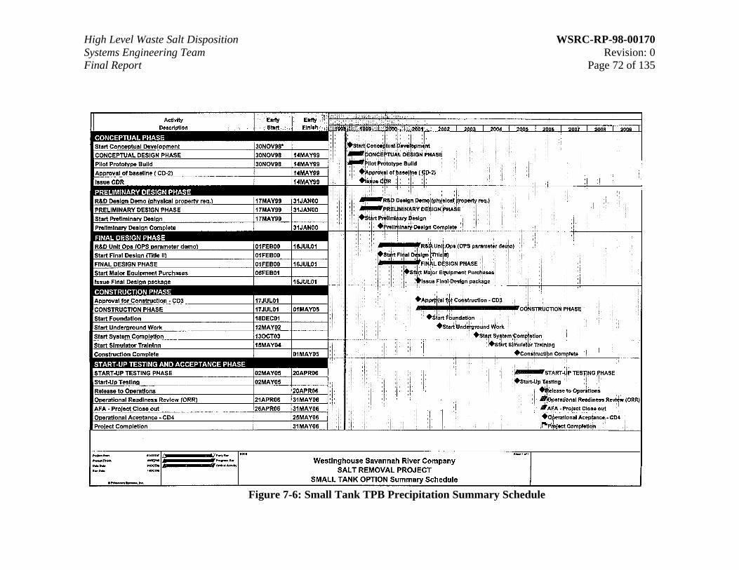
High Level Waste Salt Disposition WSRC-RP-98-00170Systems Engineering Team Revision: 0Final Report Page 72 of 135
Figure 7-6: Small Tank TPB Precipitation Summary Schedule

High Level Waste Salt Disposition WSRC-RP-98-00170Systems Engineering Team Revision: 0Final Report Page 73 of 135
7.5 Cash Flow
Cash flows were developed for each alternative to evaluate fiscal year fundingrequirements. The cash flow for each alternative was prepared on both Budget Outlayand Budget Authorization basis, reflecting the funding provided by Congress each yearfor the alternative. The project cash flows were prepared following Team approval of theproject estimates for each alternative. The early procurement of major engineeredequipment and training simulators were factored into the development of each alternativecash flow.
Budget Authorization cash flow was projected using the requirement that all funding forpurchase orders (e.g. engineered equipment) or subcontracts (e.g. engineering services)be in hand when the orders and subcontracts are awarded.
Tables 7-6 through 7-9 give a summary cash flow for each alternative.

High Level Waste Salt Disposition WSRC-RP-98-00170Systems Engineering Team Revision: 0Final Report Page 74 of 135
In Thousands of Constant Dollars
Project Cash FlowProject Cash Flow Budget Authority (BA)Budget Authority (BA) Budget Outlay (BO)Budget Outlay (BO)Caustic Side Caustic Side Total Other Total Total Other Total
Solvent ExtractionSolvent Extraction Estimated Project Project Estimated Project Project
Cost Cost Costs Cost Cost Costs
(TEC) (OPC) (TPC) (TEC) (OPC) (TPC)
FY 1999 39,284 26,384 65,668 0 26,384 26,384FY 2000 90,146 49,386 139,531 50,860 49,386 100,246FY 2001 99,526 86,760 186,286 50,860 86,760 137,620FY 2002 132,528 42,267 174,795 95,357 42,267 137,624FY 2003 166,383 42,694 209,077 225,610 42,694 268,304FY 2004 187,673 43,974 231,647 236,769 43,974 280,743FY 2005 121,949 62,311 184,260 177,824 62,311 240,135FY 2006 31,022 88,304 119,326 31,232 88,304 119,535FY 2007 2,485 49,305 51,791 2,485 49,305 51,791FY 2008 0 0
TotalTotal 870,996 491,384 1,362,3801,362,380 870,996 491,384 1,362,3801,362,380
Table 7-6: Caustic Side Solvent Extraction Summary Cash Flow

High Level Waste Salt Disposition WSRC-RP-98-00170Systems Engineering Team Revision: 0Final Report Page 75 of 135
In Thousands of Constant Dollars
Project Cash FlowProject Cash Flow Budget Authority (BA)Budget Authority (BA) Budget Outlay (BO)Budget Outlay (BO)CST - Non ElutableCST - Non Elutable Total Other Total Total Other Total
Ion ExchangeIon Exchange Estimated Project Project Estimated Project Project
Cost Cost Costs Cost Cost Costs
(TEC) (OPC) (TPC) (TEC) (OPC) (TPC)
FY 1999 33,503 25,700 59,203 7,925 25,700 33,625FY 2000 76,784 48,094 124,878 47,551 48,094 95,645FY 2001 97,034 85,576 182,610 44,263 85,576 129,838FY 2002 137,296 40,954 178,250 90,740 40,954 131,695FY 2003 147,011 41,332 188,343 199,613 41,332 240,945FY 2004 158,033 43,651 201,684 205,967 43,651 249,619FY 2005 91,625 58,830 150,455 145,226 58,830 204,056FY 2006 24,569 58,405 82,974 24,568 58,405 82,973FY 2007 1,606 15,949 17,555 1,606 15,949 17,555FY 2008 0 0
TotalTotal 767,460 418,491 1,185,9511,185,951 767,460 418,491 1,185,9511,185,951
Table 7-7: CST Non-Elutable Ion Exchange Summary Cash Flow

High Level Waste Salt Disposition WSRC-RP-98-00170Systems Engineering Team Revision: 0Final Report Page 76 of 135
In Thousands of Constant Dollars
Project Cash FlowProject Cash Flow Budget Authority (BA)Budget Authority (BA) Budget Outlay (BO)Budget Outlay (BO)Total Other Total Total Other Total
Disposal in GroutDisposal in Grout Estimated Project Project Estimated Project Project
Cost Cost Costs Cost Cost Costs
(TEC) (OPC) (TPC) (TEC) (OPC) (TPC)
FY 1999 22,148 26,440 48,587 11,465 26,440 37,905FY 2000 67,226 47,896 115,121 45,859 47,896 93,755FY 2001 83,350 35,474 118,824 62,695 35,474 98,168FY 2002 138,914 33,699 172,613 133,937 33,699 167,636FY 2003 153,715 33,699 187,414 161,808 33,699 195,507FY 2004 133,964 24,849 158,813 172,719 24,849 197,568FY 2005 32,489 44,652 77,141 43,323 44,652 87,975FY 2006 1,620 27,430 29,050 1,620 27,430 29,050FY 2007 0 0 0 0 0 0FY 2008 0 0
TotalTotal 633,426 274,138 907,564907,564 633,426 274,138 907,564907,564
Table 7-8: Direct Disposal in Grout Summary Cash Flow

High Level Waste Salt Disposition WSRC-RP-98-00170Systems Engineering Team Revision: 0Final Report Page 77 of 135
In Thousands of Constant Dollars
Project Cash FlowProject Cash Flow Budget Authority (BA)Budget Authority (BA) Budget Outlay (BO)Budget Outlay (BO)Small Tank TPBSmall Tank TPB Total Other Total Total Other Total
PrecipitationPrecipitation Estimated Project Project Estimated Project Project
Cost Cost Costs Cost Cost Costs
(TEC) (OPC) (TPC) (TEC) (OPC) (TPC)
FY 1999 32,558 26,436 58,993 11,551 26,436 37,986FY 2000 67,211 65,817 133,027 46,202 65,817 112,019FY 2001 111,445 51,538 162,983 60,269 51,538 111,807FY 2002 148,940 37,259 186,199 155,064 37,259 192,323FY 2003 180,761 37,902 218,663 194,217 37,902 232,119FY 2004 112,202 46,614 158,816 169,688 46,614 216,302FY 2005 35,490 62,106 97,596 51,616 62,106 113,722FY 2006 2,452 51,051 53,503 2,452 51,051 53,503FY 2007 0 0 0 0 0 0FY 2008 0 0
TotalTotal 691,059 378,722 1,069,7811,069,781 691,059 378,722 1,069,7811,069,781
Table 7-9: Small Tank TPB Precipitation Summary Cash Flow
High Level Waste Salt Disposition WSRC-RP-98-00170Systems Engineering Team Revision: 0Final Report Page 78 of 135
7.6 Operation and Maintenance Cost
The Operating and Maintenance (O&M) costs for each Short List alternative weredeveloped using a process which included using a “Tailored Benchmark Model”developed by the Team using the DWPF O&M staffing as a benchmark fromwhich to scale costs. As an initial step, the Team used the pre-conceptual projectlayouts and flowsheets for each alternative to estimate the following:
• Operators
• Maintenance mechanics
• Laboratory technicians
• Process area square footage
• Capital equipment replacements
• Consumable materials
• Essential materials
The “Tailored Benchmark Model” then used this data and the DWPF staffinglevels and support services costs to scale the remaining elements of O&M costs.These estimates were then reviewed by the Team and specific adjustments weremade in areas where the Team felt that direct scaling from DWPF was notrepresentative of the O&M cost for each alternative. The resulting O&M cost foreach alternative are shown below in Table 7-10. In addition, the O&M costs forSaltstone are shown where applicable.

High Level Waste Salt Disposition WSRC-RP-98-00170Systems Engineering Team Revision: 0Final Report Page 79 of 135
Table 7-10: Average Yearly O&M Costs(thousands of FY99 constant year dollars)
Caustic Side CST Non- Direct Disposal SmallSolvent Elutable Ion In Tank TPB
Cost Element Extraction Exchange Grout PrecipitationHLW Labor & Subcontracts 19,627 11,906 13,063 15,844
Consumable Materials 728 485 485 485
Support Group Services 12,033 9,651 7,853 10,307
CE & GPP 3,503 3,877 3,123 3,314
Average Essential Materials* 28,808 6,404 3,178 12,893
Vault Construction ** 16,532
Site Overhead & Fee 17,612 8,297 11,870 11,428
Average O&M Cost per Year - Alternative Specific 82,310 40,620 56,104 54,271
Saltstone O&M Cost w/ SOH*** 28,218 41,560 0 30,919
Average O&M Cost per Year including supporting Facilities 110,528 82,180 56,104 85,190
*** Saltstone O&M cost is shown for three of the alternatives, since Saltstone processes the decontaminated stream into grout.
* The annual cost for essential materials is based on the production schedule. However, for comparison purposes, an average cost per year is shown.** Vault Construction Cost is shown only for Direct Disposal in Grout alternative. The vaults used in the other alternatives are included in the Saltstone O&M Cost.
7.7 Decontamination and Decommissioning (D&D) Cost
Each of the alternatives will be decontaminated and decommissioned at the end ofthe production cycle. The estimate for the D&D cost for each alternative has beenscaled from the DWPF D&D cost estimate, which is based on engineeringjudgement and brief discussions with SRS Environmental Restoration personnel.D&D costs for each alternative are shown in Table 7-11.

High Level Waste Salt Disposition WSRC-RP-98-00170Systems Engineering Team Revision: 0Final Report Page 80 of 135
Table 7-11: D&D Costs(millions of FY99 constant year dollars)
Alternative D&D Cost
Caustic Side Solvent Extraction 124CST Non-Elutable Ion Exchange 135Direct Disposal in Grout 87Small Tank TPB Precipitation 117
7.8 Life Cycle Cost
Using the methods described in Sections 7.3 through 7.7, the Life Cycle Costs ofeach alternative were developed. Life Cycle Costs include cost components fromthe inception of the project through production and D&D. The LCCs also includethe O&M and D&D costs for the Saltstone Facility, which is a part of the overallsalt processing mission.
7.9 Production Model Analysis
After the Selection Phase flowsheets were defined, the Production Model(ProdMod) was run for each alternative. By incorporating the operatingparameters of each alternative, ProdMod was able to predict how the facilities inthe HLW System, including the specific salt alternative facility, would operate.Prior to running the model, a number of generic assumptions were defined andused for the alternatives.
7.9.1 Generic ProdMod Assumptions
The major assumptions were:
• Influent streams will be as currently forecast. No new or additional Canyon orDWPF missions are assumed.
• The HLW facilities can support a significant increase in intra- and inter-areatransfers in order to support a salt solution feed of six million gallons per year.
• Concentrated supernate can be stored in “old style tanks” (Tanks 4-8) if spacein Type III tanks is not available.
• The current contents of Tank 49 will be transferred to Tank 48 or processed toSaltstone. Once de-inventoried, Tank 49 will be returned to Tank Farm wastestorage service.

High Level Waste Salt Disposition WSRC-RP-98-00170Systems Engineering Team Revision: 0Final Report Page 81 of 135
• Tank 50 will continue to be used to receive Effluent Treatment Facility (ETF)concentrate until the startup of salt processing. The Saltstone facility will bein a “partial lay-up” mode except when it must be operated to process Tank 50material.
• No long, unplanned outages are assumed anywhere in the HLW System. Theevaporators (2F, 2H and the Replacement High Level Waste Evaporator),ESP, and DWPF are expected to operate continuously throughout the period,except during planned outages.
• Existing FFA and STP commitments remain in effect.
7.9.2 ProdMod Results
In addition to the generic assumptions listed above, ProdMod used the startupdates, processing rates, and other flowsheet information for each alternative asinputs. Annual feed from the tank farms to the salt and sludge processingfacilities was selected to allow the HLW System to maximize processingcapabilities while operating within the bounds of set volume, waste compositionand other system constraints.
ProdMod calculates material flows throughout the HLW System on a year-by-year basis and ensures that material balances do not exceed any of the HLWSystem constraints (e.g., Tank Farm storage capacity based on physical andadministrative limits). ProdMod generates the following types of information:
• Tank Farm material balances
• Salt and sludge removal and processing schedules and volumes
• Waste Removal project schedules
• Tank closure schedules
• DWPF recycle stream volume
• Evaporation requirements
• Inter-area transfers (to maximize tank space usage between the two tankfarms)
• Saltstone processing schedules, including vault usage
• Canister storage, including the schedules which show when additional canisterstorage space must be constructed

High Level Waste Salt Disposition WSRC-RP-98-00170Systems Engineering Team Revision: 0Final Report Page 82 of 135
These results are used as the basis for planning and operation throughout theHLW System. The individual facilities in the HLW System use these results todetermine what scope to accomplish in each fiscal year to support the needs of theHLW System. This information is further refined by facility and divisionplanners to determine what specific month or week a facility can take outages orwhen individual transfers should occur. The HLW Financial Model uses theProdMod results in its budget preparations to ensure that adequate funding isrequested for each fiscal year to fund the integrated scope requirements of theHLW system. A summary of key results of the ProdMod runs for each saltprocessing alternative is shown in Table 7-12.
Table 7-12: Key Results Summary Information
Key ResultsCaustic SideSolventExtraction
CST Non-ElutableIonExchange
DirectDisposal inGrout
Small TankTBPPrecipitation
Salt Processing Plant Operations Initiated 5/07 3/07 3/06 5/06
Number of Years of Salt Plant Operations 13 13 13 15
Meets Regulatory Commitments (FFA /STP) Yes Yes Yes Yes
Planned Canister Production Rate Per Year 225 225 235 210
Number of Old Style Tanks Utilized forTemporary Storage of Additional Waste
2 2 2 2
Year the 24 “Old Style” Tanks are Closed 2016 2016 2015 2016
Salt and Sludge Processing OperationsCompleted
6/19 3/19 4/18 9/20
Processing and Storage Facilities Closed 6/21 3/21 4/20 9/22
Canisters Produced 5084 5084 5084 5084
Year Canister Shipments Complete 2025 2025 2025 2025
Class A Vaults – Onsite Disposal 14 15 2 18
Class C Vaults – Onsite Disposal 0 0 13 0

High Level Waste Salt Disposition WSRC-RP-98-00170Systems Engineering Team Revision: 0Final Report Page 83 of 135
The ProdMod annual canister production rate for each alternative is driven by theneed to minimize costs through completion of sludge processing at the same timeas salt processing. This is due to the blending of the salt solution feed stream withsludge material to avoid the production of additional canisters.
The ProdMod runs for each alternative meet Federal Facility Agreements andSTP regulatory requirements. These requirements include closure of the “oldstyle” tanks, commitments regarding DWPF canister production (average of 200cans per year) and removal of waste inventory from the HLW tanks by FY2028.
7.10 HLW System LCC
In addition to the differences of construction and operating costs of the specificSalt Disposition Facility, each alternative also differs in its effect on the HLWSystem schedule and costs. Differences can include: the year salt processing canbegin; the schedule for waste tank closure (ending tank operating costs); theschedule for waste tank waste removal; and, most importantly, the schedule forcompletion of the waste removal program. Given the high annual fixed costs ofoperating the entire HLW System, there are significant cost benefits forcompleting waste removal as soon as possible ending these costs. To quantify theLCC impacts on the HLW System, the HLW Financial Model was used. Thismodel is used routinely to estimate the HLW System LCC of various fundingscenarios.
The Financial Model uses FY99 as the base operating year. For each subsequentyear the cost of continuing scope is escalated and the cost impact of major,programmed scope changes is factored into the analysis. Major scope changescan include such items as facility construction and startup, tank closures, essentialmaterials, melter replacements, vault construction, tank waste removal, andcanister shipments. Line item projects, including D&D, are included according totheir project schedules. Waste removal and tank closure are shown tank-by-tank.The scope changes are based on the ProdMod detailed results described inSection 7.9.
The results of the model are shown in Tables 7-13 through Table 7-15, whichshow HLW System LCC in constant, escalated, and discounted dollars.

High Level Waste Salt Disposition WSRC-RP-98-00170Systems Engineering Team Revision: 0Final Report Page 84 of 135
Table 7-13: HLW Total System LCC (Escalated Dollars)
Work Scope
Caustic SideSolvent
Extraction
CST Non-Elutable IonExchange
Direct Disposalin Grout
Small Tank TPBPrecipitation
H Tank FarmH Tank Farm Operations 1,834 1,815 1,699 1,994LI: Replacement Evap 7 7 7 7LI: Tk Fm Service Upgds I 1 1 1 1LI: E Hill Piping 34 34 34 34LI: StormWater 10 10 10 10
Sub-Total 1,886 1,867 1,751 2,046
F Tank FarmF Tank Farm Operations 1,179 1,173 1,085 1,245LI: Tk Fm Service Upgds II 26 26 26 26
Sub-Total 1,205 1,199 1,111 1,270
Waste Removal & Tank ClosuresWR Ops w/ Demo Projs 197 194 191 218LI: WR from Tanks 813 813 796 830WR: Tank Closure 721 725 705 740
Sub-Total 1,731 1,732 1,692 1,788
Feed Prep. & Sludge Ops 1,888 1,856 1,732 2,051
Salt AlternativeLI: Salt Alternative 1,511 1,307 991 1,169LI: Salt Alternative Upgrades 179 153 127 142Salt Alternative Ops 1,522 789 1,026 1,201Saltstone Operations 565 594 37 703Salt Alternative & Saltstone D&D 228 248 154 225
Sub-Total 4,004 3,091 2,335 3,440
VitrificationVitrification Ops 4,115 4,054 3,821 4,479Failed Equip. Stor. Vaults 16 16 16 16LI: Vit Upgrades 186 186 186 186
Sub-Total 4,317 4,257 4,023 4,682
Glass Waste Storage 272 272 281 264
Support FacilitiesCIF Operations 803 803 803 803ETF Operations 537 528 495 584
Sub-Total 1,340 1,331 1,298 1,387
Facility D&D 420 417 401 434
GRAND TOTAL 17,064 16,023 14,625 17,362
(Budget Authority millions of escalated dollars)
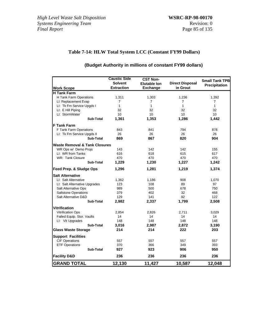
High Level Waste Salt Disposition WSRC-RP-98-00170Systems Engineering Team Revision: 0Final Report Page 85 of 135
Table 7-14: HLW Total System LCC (Constant FY99 Dollars)
Work Scope
Caustic SideSolvent
Extraction
CST Non-Elutable Ion
ExchangeDirect Disposal
in Grout
Small Tank TPBPrecipitation
H Tank FarmH Tank Farm Operations 1,311 1,303 1,236 1,392LI: Replacement Evap 7 7 7 7LI: Tk Fm Service Upgds I 1 1 1 1LI: E Hill Piping 32 32 32 32LI: StormWater 10 10 10 10
Sub-Total 1,361 1,353 1,286 1,442
F Tank FarmF Tank Farm Operations 843 841 794 878LI: Tk Fm Service Upgds II 26 26 26 26
Sub-Total 869 867 820 904
Waste Removal & Tank ClosuresWR Ops w/ Demo Projs 143 142 142 155LI: WR from Tanks 616 618 615 617WR: Tank Closure 470 470 470 470
Sub-Total 1,229 1,230 1,227 1,242
Feed Prep. & Sludge Ops 1,296 1,281 1,219 1,374
Salt AlternativeLI: Salt Alternative 1,362 1,186 908 1,070LI: Salt Alternative Upgrades 123 108 89 97Salt Alternative Ops 989 500 678 750Saltstone Operations 379 402 32 468Salt Alternative D&D 129 141 92 122
Sub-Total 2,982 2,337 1,799 2,508
VitrificationVitrification Ops 2,854 2,826 2,711 3,029Failed Equip. Stor. Vaults 14 14 14 14LI: Vit Upgrades 148 148 148 148
Sub-Total 3,016 2,987 2,872 3,190Glass Waste Storage 214 214 222 203
Support FacilitiesCIF Operations 557 557 557 557ETF Operations 370 366 349 393
Sub-Total 927 923 906 950
Facility D&D 236 236 236 236
GRAND TOTAL 12,130 11,427 10,587 12,048
(Budget Authority in millions of constant FY99 dollars)
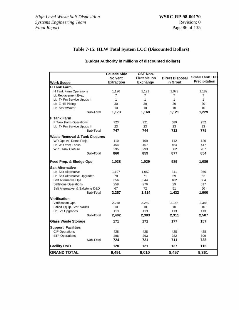
High Level Waste Salt Disposition WSRC-RP-98-00170Systems Engineering Team Revision: 0Final Report Page 86 of 135
Table 7-15: HLW Total System LCC (Discounted Dollars)
Work Scope
Caustic SideSolvent
Extraction
CST Non-Elutable IonExchange
Direct Disposalin Grout
Small Tank TPBPrecipitation
H Tank FarmH Tank Farm Operations 1,126 1,121 1,073 1,182LI: Replacement Evap 7 7 7 7LI: Tk Fm Service Upgds I 1 1 1 1LI: E Hill Piping 30 30 30 30LI: StormWater 10 10 10 10
Sub-Total 1,173 1,168 1,121 1,229
F Tank FarmF Tank Farm Operations 723 721 689 752LI: Tk Fm Service Upgds II 23 23 23 23
Sub-Total 747 744 712 775
Waste Removal & Tank ClosuresWR Ops w/ Demo Projs 110 109 112 120LI: WR from Tanks 454 457 464 447WR: Tank Closure 295 293 302 287
Sub-Total 860 859 877 854
Feed Prep. & Sludge Ops 1,038 1,029 989 1,086
Salt AlternativeLI: Salt Alternative 1,197 1,050 811 956LI: Salt Alternative Upgrades 78 71 59 62Salt Alternative Ops 656 344 482 504Saltstone Operations 259 276 29 317Salt Alternative & Saltstone D&D 67 72 51 60
Sub-Total 2,257 1,814 1,432 1,900
VitrificationVitrification Ops 2,278 2,259 2,188 2,383Failed Equip. Stor. Vaults 10 10 10 10LI: Vit Upgrades 113 113 113 113
Sub-Total 2,402 2,383 2,311 2,507
Glass Waste Storage 171 171 177 157
Support FacilitiesCIF Operations 428 428 428 428ETF Operations 296 293 282 309
Sub-Total 724 721 711 738
Facility D&D 120 121 127 116
GRAND TOTAL 9,491 9,010 8,457 9,361
(Budget Authority in millions of discounted dollars)

High Level Waste Salt Disposition WSRC-RP-98-00170Systems Engineering Team Revision: 0Final Report Page 87 of 135
7.11 Application of Contingency to Life Cycle Cost
This section discusses contingency analysis of the LCC, impacts of thealternatives on HLW System schedules, calculation of the LCC point estimates,and calculation of the upper/lower limit of the “boxes”.
7.11.1 Contingency Analysis of the Life Cycle Cost
The LCC contingency analysis was performed applying the same methodologyused for TEC and OPC. Since the LCC variables are not as recognized as thoseused in the TEC and OPC analysis, the Team developed appropriate terms andvariables for the LCC analysis considering SME advice.
Table 7-16 displays the Monte Carlo contingency percentage at the 50%probability point for cost overruns. As was done for the TEC and OPC estimates,the contingency percent at the 50% probability of cost overrun was applied to theLCC estimates.
Table 7-16: Contingency Percentage (50% Probability Point)
Alternative Contingency@ 50% Prob.
Caustic Side Solvent Extraction 4.2%CST Non-Elutable Ion Exchange 10.2%Direct Disposal in Grout 8.4%Small Tank TPB Precipitation 7.7%
The contingency is notably lower on the Caustic Side Solvent Extractionalternative. This is due to the favorable probability ranges applied by the Team tothe TEC Design Complexity variable.
7.11.2 HLW System Schedule Impacts
Each alternative has different impacts on the operating cycle of the HLW System.The LCC “point” estimate for each alternative was defined by the Team toinclude the LCC (including the 50% probability of overrun contingency from theMonte Carlo analysis) plus the HLW System schedule impacts. In order tocalculate the HLW System schedule impact for each alternative, the LCC wassubtracted from the LCC of the entire HLW System for that alternative. Theresult was termed the “Systems Impacts on LCC”.

High Level Waste Salt Disposition WSRC-RP-98-00170Systems Engineering Team Revision: 0Final Report Page 88 of 135
The important factor is the differences in how the alternatives impact the totalHLW System. Therefore, the Systems Impact on LCC for Direct Disposal inGrout was set at zero. The Systems Impact for the other three alternatives wasthen set as the delta from Direct Disposal in Grout.
7.11.3 LCC Point Estimate
The LCC point estimate for each alternative can be calculated by using thefollowing:
• Total LCC
• The 50% probability of overrun contingency
• The HLW System Schedule Impacts
Since the HLW System Schedule Impacts were not part of the Monte Carloanalysis, contingency was applied to the LCC prior to adding the HLW SystemSchedule Impacts. The formula for calculating the LCC point estimates at the50% probability of overrun point from the Monte Carlo analysis is:
Total LCC Point Estimate = (LCC x [1 + Contingency Percentage]) + HLWSystem Impacts
The LCC point estimates for each of the alternatives are shown in Table 7-17below:
Table 7-17: Total LCC Point Estimates(Millions of FY99 constant year dollars)
Alternative
Total LCC
Estimate
Contigency
@ 50%Confidence
Interval
HLWOverallSystemImpacts
TotalLCCPoint
Estimate
Caustic Side SolventExtraction
2,983 125 360 3,468
CST Non-Elutable IonExchange
2,336 238 303 2,877
Direct Disposal in Grout 1,799 151 0 1,950Small Tank TPBPrecipitation
2,507 193 753 3,453

High Level Waste Salt Disposition WSRC-RP-98-00170Systems Engineering Team Revision: 0Final Report Page 89 of 135
7.11.4 LCC Upper/Lower Limits
In order to determine the upper limits of the LCC Point Estimate “box”, the Teamdecided to use the contingency from the Monte Carlo analysis at the 20%probability of overrun point (i.e. 80% confidence that the LCC costs will notoverrun). As an example of the process, the calculation for the Small Tank TPBPrecipitation alternative is shown below:
Example: Small Tank TPB Precipitation Alternative (in thousands of FY99constant year dollars)
TECTotal TEC w/o contingency = 520,044Contingency percent at 20% probability of overrun = 47.5%Difference between 50% probability and 20% probability = 47.5 – 33.0 =14.5%Additional TEC contingency = 520,044 x 14.5% = 75,406
OPCTotal OPC w/o contingency = 272,226Contingency percent at 20% probability of overrun = 64.5% Differencebetween 50% probability and 20% probability = 64.5 – 38.9 = 25.6%Additional OPC contingency = 272,226 x 25.6% = 69,690
LCCTotal LCC w/o contingency = 2,507,646Contingency percent at 20% probability of overrun = 14.3%LCC Contingency = 2,507,646 x 14.3% = 358,593
Upper Limit of BoxTherefore, the upper limit of the box is calculated by adding the additionalTEC contingency, the additional OPC contingency, the LCC contingency,the LCC total and the HLW System Schedule Impact:
75,406 + 69,690 + 358,593 + 2,507,646 + 752,667 = 3,764,003

High Level Waste Salt Disposition WSRC-RP-98-00170Systems Engineering Team Revision: 0Final Report Page 90 of 135
The Team determined that the lower limit of the LCC point estimate “box” shouldbe based on the contingency from the Monte Carlo analysis at the 60% probabilityof overrun. The calculation process shown in the example above is applied tocalculate the lower limit results. The results of these calculations are summarizedin Table 7-18 below:
Table 7-18: Upper/Lower Box Limits(Millions of FY99 constant year dollars)
Alternative Lower Limitof Boxes
Upper Limitof Boxes
Caustic Side Solvent Extraction 3,354 3,888CST Non-Elutable Ion Exchange 2,782 3,236Direct Disposal in Grout 1,866 2,259Small Tank TPB Precipitation 3,374 3,764

High Level Waste Salt Disposition WSRC-RP-98-00170Systems Engineering Team Revision: 0Final Report Page 91 of 135
8.0 Uncertainties
The purpose of this section is to discuss the specific use of uncertainties by the Team andto report the uncertainties associated with each alternative for the selection process.
The Team defined uncertainties as potential variances in the cost or schedule of analternative. In turn, risks were defined as issues that could cause uncertainties. Themajor concern of the selection process was identifying, assessing and minimizing issuesthat could increase the cost associated with or prevent the success of an alternative inmeeting the Mission Need. Since tools have been used in the cost estimating process toaccommodate “normal” project cost and schedule variations within the estimates, theTeam limited the potential cost and schedule impacts that could lead to “uncertainties” tothose arising from specific attributes of the alternative under consideration. Uncertaintiesmay result in either increases or decreases in cost and/or schedule estimates. No scheduleimpacts were allowed to be greater than five years, as that was assumed to be the greatesttime period required to resolve any issue. Only the regulatory uncertainty related toapproval of the grout waste as “other than HLW” was assigned a value of five years.
Uncertainties are the Team quantification of the potential impact of identified issues. Inorder to be useful, each uncertainty used in the selection process was required to beassigned a value in dollars, months or both. For the same reason, uncertainties with costand schedule impacts too small to significantly contribute to the discrimination of thealternatives were not carried into the selection process. These potential impacts wereassumed to be within the contingency estimates, within the stated value range of the LifeCycle Cost Point Estimate or within the baseline schedule for each alternative.
Two functions are provided by the use of uncertainties. First, as described in the RiskManagement section, uncertainties play a key role in the evaluation of risks and thegeneration of risk handling strategies. Second, uncertainties permit the Short Listalternatives to be evaluated on a consistent basis. The need for the use of uncertainties inthe evaluation process is derived from the Team decision to compare the alternatives onthe basis of cost to achieve assured success. Assured success means that credible riskhandling strategies have been established and appropriate cost and schedule impactsevaluated and attributed to the alternative for each identified uncertainty. The value ofthe cost of assured success is the Team estimate of the cost of implementing analternative assuming an unfavorable outcome of the identified uncertainties.
After cost and schedule impacts for each uncertainty used in the selection process wereestablished a combination method was required to provide the total impact on the cost ofthe alternative. While the cost uncertainties for a given alternative could simply beadded, schedule uncertainties could not be handled as simply. Since the schedule impactsof the uncertainties for an alternative were not necessarily on critical path or sequential,

High Level Waste Salt Disposition WSRC-RP-98-00170Systems Engineering Team Revision: 0Final Report Page 92 of 135
the Team had to analyze the individual impacts of each schedule uncertainty on theoverall implementation schedule of the alternative. The results of this analysis arediscussed in Section 9.0 (Selection). Each alternative had an overall schedule impactestablished, representing the contribution of all schedule uncertainties.
In order to provide a useful comparison of the alternatives, it was necessary to convertthese overall schedule impacts into cost impacts. The financial model of the SRS HLWSystem generated estimates of the cost of operating the HLW System for the length oftime required by each alternative to de-inventory the HLW Tanks. The three highest costalternatives were assessed with their difference in cost from the lowest cost alternative.
Table 8-1 is a list of the uncertainties used for each of the Short List alternatives in theselection process with the cost and/or schedule impact assigned to the uncertainty by theTeam.
Table 8-1: Quantified Uncertainties
Caustic Side Solvent Extraction
Uncertainty Statement Explanatory Note
Decomposition/Degradation products maynegatively affect downstream operations.
$1 million cost increase for 2 carbon bedfilters.
Crud formation in the system at theorganic to aqueous interface.
$500,000 cost increase for crud separationtanks.
Insufficient understanding of theoperating window with respect to feedimpurities. (DNFSB 96-1)
14 month delay in completing preliminarydesign.
Difficulty in filtration of sludge and/orMST will produce low filtrate flow ratesand require frequent cleaning
$1.5 million cost increase for the largerfilters.$5 million cost increase for the largerpumps.
TRU decontamination with MST is notadequate with the design residence time.
$50 million cost increase (based on onehalf the estimate for cost savings formoving the MST strike to the Tank Farm).
Public acceptability may not be achieved. $500,000 cost increase for public relationsand analysis

High Level Waste Salt Disposition WSRC-RP-98-00170Systems Engineering Team Revision: 0Final Report Page 93 of 135
Table 8-1: Quantified Uncertainties (continued)
Caustic Side Solvent Extraction
Uncertainty Statement Explanatory Note
DOE independent project review andacceptance may impact projectmilestones.
Schedule impact of 1 month at end ofconceptual design, 1 month at the end ofpreliminary design, 2 month at the end offinal design and 1 month prior toradioactive operations.
The requirement for NRC licensing mayimpact the cost and schedule.
18 month delay to radioactive operations.Additional $1 million cost. SAR maycause 4 month delay in completingpreliminary design.
DOE lack of support of required budgetand schedule may delay new facilitystartup.
6 month schedule impact in the first year.7 month schedule impact in the secondyear.7 month schedule impact in the third year.
SRS infrastructure may not support theproject needs.
$31 million cost increase for overtimeresulting from staffing delays.
Pressure on ‘old’ infrastructure willincrease, endangering schedule due tothree fold increase in flow requirementsfrom HTF and FTF. This would endangerperformance of infrastructure.
9 month delay in completing salt removalfrom a production schedule delay to reachsalt solution feed rate assumption. Basis:50% material movement in the first yearresults in 6 months and 75% materialmovement in the second year results in 3months.
Improper contract strategy for designwork may impact the schedule.
6 month delay in completing conceptualdesign.
Research and development workperformed must be coordinated with thedesign effort.
3 month delay in completing preliminarydesign.
Geotechnical problems with sitinglocations may cause schedule delays.
12 month delay in start of Final design.$126 million cost increase (based on 10%of TEC + $34 million for substructuregrout + contingency percentage).
A clearly defined safety strategy shouldbe agreed to by the end of conceptualdesign to preclude schedule impacts.
2 month delay in start of preliminarydesign.

High Level Waste Salt Disposition WSRC-RP-98-00170Systems Engineering Team Revision: 0Final Report Page 94 of 135
Table 8-1: Quantified Uncertainties (continued)
Caustic Side Solvent Extraction
Uncertainty Statement Explanatory Note
Solvent estimated unit cost rate may bereduced.
Solvent extractant cost bases decreasesfrom $500 to $175 per gram, resulting ina $190 million life cycle cost decrease.
Solvent estimated consumption cost maybe reduced.
Change cost bases to completereplacement of solvent every 2 years andsolvent extractant cost bases to $175 pergram resulting in a $51 million costdecrease.
The interfacing facilities operationalschedules may impact completion oftie-ins to the new facility.
2 month production delay for DWPF toinstall new transfer line.
GT-73 unit operations may not berequired.
$25 million cost decrease.
CST Non-Elutable Ion Exchange
Uncertainty Statement Explanatory Note
Resin bed temperature control duringoperational conditions and loaded spentresin temperature control.
$10 million cost increase for safety classemergency cooling and temperaturemonitoring.
Can pressure gradients crush the resinduring column operations?
$2.5 million cost increase for 4 additionalcolumns.$2.5 million cost increase for associatedjumpers.$2.6 million cost increase for 2 additionalpersonnel during the operational life of thefacility.
Difficulty in filtration of sludge and/orMST will produce low filtrate flow ratesand require frequent cleaning
$1.5 million cost increase for the largerfilters.$5 million cost increase for the largerpumps.
TRU decontamination with MST is notadequate with the design residence time.
$50 million cost increase (based on onehalf the estimate for cost savings formoving the MST strike to the Tank Farm).

High Level Waste Salt Disposition WSRC-RP-98-00170Systems Engineering Team Revision: 0Final Report Page 95 of 135
Table 8-1: Quantified Uncertainties (continued)
CST Non-Elutable Ion Exchange
Uncertainty Statement Explanatory Note
Process chemistry understanding andapplication are still under development,resulting in 96-1 lessons learned not yetimplemented
12 month delay in completing preliminarydesign.
CST will require “requalification” of glassform.
$10 million cost increase to support glassrequalification.
Major sample station modificationaffecting DWPF operations.
$5 million cost increase for sample cellmodifications.
CST resin fines may collect indownstream filters, elbows, imperfectwelds, and instrument lines.
$2 million cost increase for relatedmodifications (e.g., shielding).
DOE independent project review andacceptance may impact projectmilestones.
Schedule impact of 1 month at end ofconceptual design, 1 month at the end ofpreliminary design, 2 months at the end offinal design and 1 month prior toradioactive operations.
The requirement for NRC licensing mayimpact the cost and schedule.
18 month delay to radioactive operations.Additional $1 million cost. SAR maycause 4 month delay in completingpreliminary design.
The interfacing facilities operationalschedules may impact completion of tie-ins to the new facility.
2 month production delay for DWPF toinstall new transfer line.
DOE lack of support of required budgetand schedule may delay new facilitystartup.
5 month schedule impact in the first year.5 month schedule impact in the secondyear.4 month schedule impact in the third year.
SRS infrastructure may not support theproject needs.
$26.5 million cost increase for overtimeresulting from staffing delays.

High Level Waste Salt Disposition WSRC-RP-98-00170Systems Engineering Team Revision: 0Final Report Page 96 of 135
Table 8-1: Quantified Uncertainties (continued)
CST Non-Elutable Ion Exchange
Uncertainty Statement Explanatory Note
Pressure on ‘old’ infrastructure willincrease, endangering schedule due tothree fold increase in flow requirementsfrom HTF and FTF. This would endangerperformance of infrastructure.
9 month delay in completing salt removalfrom a production schedule delay to reachsalt solution feed rate assumption. Basis:50% material movement in the first yearresults in 6 months and 75% materialmovement in the second year results in 3months.
Improper contract strategy for designwork may impact the schedule.
6 month delay in completing conceptualdesign.
Research and development workperformed must be coordinated with thedesign effort.
6 month delay in completing preliminarydesign.
Geotechnical problems with sitinglocations may cause schedule delays.
12 month delay in start of final design.$122 million cost increase (based on 10%of TEC + $34 million for substructuregrout + contingency percentage).
A clearly defined safety strategy shouldbe agreed to by the end of conceptualdesign to preclude schedule impacts.
2 month delay in the start of preliminarydesign.
Increased foaming in the DWPF ChemicalProcess Cell.
$5 million cost increase to concentrate theCST slurry.
GT-73 unit operation may not be required. $27 million cost decrease.
Hydrogen generation in the loadedcolumn.
Tankage for hydrogen gas collection andassociated safety equipment.$30 million cost increase.

High Level Waste Salt Disposition WSRC-RP-98-00170Systems Engineering Team Revision: 0Final Report Page 97 of 135
Table 8-1: Quantified Uncertainties (continued)
Direct Disposal in Grout
Uncertainty Statement Explanatory Note
Existing vault design may have to beupgraded with liners, ventilationupgrades, temperature monitoring,leachate collection, capping/backfilling,elimination of floor penetrations, HEPAfiltration of moist atmosphere and theaddition of cell access for failedequipment disposal.
$5 million cost increase for long termhydrogen collection system.
Difficulty in filtration of sludge and/orMST will produce low filtrate flow ratesand require frequent cleaning
$1.5 million cost increase for the largerfilters.$5 million cost increase for the largerpumps.
TRU decontamination with MST is notadequate with the design residence time.
$50 million cost increase (based on onehalf the estimate for cost savings formoving the MST strike to the Tank Farm).
Process not acceptable to general public. 24 month delay in start of final design.Can start at end of conceptual designbased on NEPA documentation.
Technical regulatory agencies may delayapprovals.
5 year delay to complete construction forhigh level waste in SC. 2 year delay inradioactive operation for redesign andEIS.
Process not technically supportive offuture missions (e.g. can-in-can)
$50 million cost increase to supportcommitment to can-in-can mission.
DOE independent project review andacceptance may impact projectmilestones.
Schedule impact of 1 month at end ofconceptual design, 1 month at the end ofpreliminary design, 2 months at the end offinal design and 12 months prior toradioactive operations.
DOE lack of support of required budgetand schedule may delay new facilitystartup.
3 month schedule impact in the first year.5 month schedule impact in the secondyear.
SRS infrastructure may not support theproject needs.
$20 million cost increase for overtimeresulting from staffing delays.

High Level Waste Salt Disposition WSRC-RP-98-00170Systems Engineering Team Revision: 0Final Report Page 98 of 135
Table 8-1: Quantified Uncertainties (continued)
Direct Disposal in Grout
Uncertainty Statement Explanatory Note
Pressure on ‘old’ infrastructure willincrease, endangering schedule due tothree fold increase in flow requirementsfrom HTF and FTF. This would endangerperformance of infrastructure.
9 month delay in completing salt removalfrom a production schedule delay to reachsalt solution feed rate assumption. Basis:50% material movement in the first yearresults in 6 months and 75% materialmovement in the second year results in 3months.
Improper contract strategy for designwork may impact the schedule.
6 month delay in completing conceptualdesign.
Geotechnical problems with sitinglocations may cause schedule delays.
12 month delay in start of final design.$105 million cost increase (based on 10%of TEC + $34 million for substructuregrout + contingency percentage).
GT-73 unit operations may not berequired.
$27 million cost decrease.
DWPF recycle stream does not containcesium concentration assumed in HLWSystem Plan.
$65 million cost decrease. Basis is DWPFrecycle rerouted to ETF saving evaporatoroperation.
Suspect product may not be able to berecovered.
$9 million cost increase based onabandoning a vault.
Small Tank TPB Precipitation
Uncertainty Statement Explanatory Note
Close coupled unit operations addsproduction complexity. Salt Cell inDWPF has to be operated in this option.
9 month delay in completing salt removal.Basis: 3 months delay to go from 75% to100% assumed production rate. 6 monthsto realize assumed efficiencies.
Benzene releases may exceed permitlevels due to additional (unknown)catalytic effects or catalyst build-upthrough plate-out.
Benzene emission reduction systemestimated at $5 million to meet permitlimits.
Process will not produce the DF requiredbecause of slow kinetics of MST andTPB.
$14 million cost increase for additionalCSTR.

High Level Waste Salt Disposition WSRC-RP-98-00170Systems Engineering Team Revision: 0Final Report Page 99 of 135
Table 8-1: Quantified Uncertainties (continued)
Small Tank TPB Precipitation
Uncertainty Statement Explanatory Note
Geotechnical problems with sitinglocations may cause schedule delays.
12 month delay in start of Final design.$111 million cost increase (based on 10%of TEC + $34 million for substructuregrout + contingency percentage).
DOE independent project review andacceptance may impact projectmilestones.
Schedule impact of 1 month at end ofconceptual design, 1 month at the end ofpreliminary design, 2 months at the end offinal design and 1 month prior toradioactive operations.
The requirement for NRC licensing mayimpact the cost and schedule.
18 month delay to radioactive operations.Additional $1 million cost. SAR maycause 4 month delay in completingpreliminary design.
The interfacing facilities operationalschedules may impact completion of tie-ins to the new facility.
6 month production delay for DWPF forSPC modifications.
DOE lack of support of required budgetand schedule may delay new facilitystartup.
5 month schedule impact in the first year.6 month schedule impact in the secondyear.5 month schedule impact in the third year.
SRS infrastructure may not support theproject needs.
$22 million cost increase for overtimeresulting from staffing delays.
Pressure on ‘old’ infrastructure willincrease, endangering schedule due tothree fold increase in flow requirementsfrom HTF and FTF. This would endangerperformance of infrastructure.
9 month delay in completing salt removalfrom a production schedule delay to reachsalt solution feed rate assumption. Basis:50% material movement in the first yearresults in 6 months and 75% materialmovement in the second year results in 3months.
Improper contract strategy for designwork may impact the schedule.
6 month delay in completing conceptualdesign.
Research and development workperformed must be coordinated with thedesign effort.
6 month delay in completing preliminarydesign.

High Level Waste Salt Disposition WSRC-RP-98-00170Systems Engineering Team Revision: 0Final Report Page 100 of 135
Table 8-1: Quantified Uncertainties (continued)
Small Tank TPB Precipitation
Uncertainty Statement Explanatory Note
A clearly defined safety strategy shouldbe agreed to by the end of conceptualdesign to preclude schedule impacts.
2 month delay in start of preliminarydesign.
It should be noted that the Team recognized one uncertainty that was not addressed.Recent changes in regulations have raised the possibility that the design of theSaltstone/Grout vaults may have to be upgraded. While this is an uncertainty that couldbe applied to each alternative, the Team chose not to include it in the selection process.The reasons for this were:
• Since it was equally applicable to each alternative, it would provide no discriminationbetween them;
• The scope was currently under evaluation and could not be assigned a value with anyreal confidence;
• The cost of the upgrades was clearly insignificant when compared to Life Cycle Cost.
The Team reviewed the results of the uncertainty analysis and determined the costuncertainties were small when compared to the assigned contingency values and therange between the upper and lower point estimate limits for the alternatives. The Teamdecided to eliminate this uncertainty component from further consideration in theselection process because sufficient allowance existed in the contingency and pointestimate limits. On the other hand, the monetary value of the schedule uncertainty wassignificant. This uncertainty was applied as a “whisker” to the Life Cycle Cost PointEstimate for each alternative as depicted in Section 9.0 (Selection).

High Level Waste Salt Disposition WSRC-RP-98-00170Systems Engineering Team Revision: 0Final Report Page 101 of 135
9.0 Selection
The purpose of this section is to summarize the processes used to establish the Initial Listand Short List of alternatives, identify the four Short List alternatives, and describe theprocess used for selecting the recommended alternatives. Figure 9-1 summarizes thetotal process.
Cost &
Schedule
UncertaintyApplication e.g.
Short ListSelectionCriteria
RecommendedAlternative& Backup
Screen RatingSelect
AlternativesSelectionCriteria
Cha
rter
& M
issi
on
Technology
Safety
Engineering
CurrentMissions
Cost &Schedule
FutureMissions
Initial List
Evaluation Criteria( WeightingFactors)
Planning &
Preparation
Preferred
Alternative(s)
Fun
ctio
ns &
Req
uire
men
ts
Phase I
(Identification)
Phase II
(Investigaton)
Phase III
(Selection)
· Environmental· Stakeholder
Conceptual DesignProject Definition
Preconceptual DesignR&D Results
Flowsheets Risk AssessmentsUnit Operations Risk
AssessmentsLife Cycle Cost Analysis
Detailed Schedule
Flowsheet DevelopmentField Validations
Prelim. Risk AssessmentsPrelim Risk Mitigation Strategies
Prelim Cost AnalysisPrelim Schedule Estimate
Detailed Literature SearchShort List Identification
BrainstormingSite Solicitations
SRTC & Nat. LabsEM Focus AreasPrelim. Lit Search
DOE Site HistoricalInitial List Identification
Figure 9-1: Selection Process Summary
9.1 Initial List Selection Process
The purpose of the Identification Phase was to establish a comprehensive list ofalternative technologies and to identify a working list of alternative processes thatappeared capable of being successfully deployed on the required time scale.
The Team grouped proposed alternatives into categories based upon technology,which were then screened for basic viability (in this case all of the categoriespassed). The alternatives embodied within the categories were then reviewed

High Level Waste Salt Disposition WSRC-RP-98-00170Systems Engineering Team Revision: 0Final Report Page 102 of 135
individually and screened against criteria from the Initial Design Input. The mostfavorable alternatives from each category were then carried forward to the InitialList:
• Fractional Crystallization - DWPF Vitrification
• Electrochemical Separation and Destruction – DWPF Vitrification
• Elutable Ion Exchange - DWPF Vitrification
• Potassium Removal followed by TPB Precipitation
• Acid Side Ion Exchange - DWPF Vitrification
• Crystalline Silicotitanate (CST) Ion Exchange – DWPF Vitrification
• Crystalline Silicotitanate (CST) Ion Exchange – New Facility Vitrification
• Zeolite Ion Exchange - DWPF Vitrification
• Crystalline Silicotitanate (CST) Ion Exchange – Ceramic Wasteform
• Reduced Temperature ITP
• Catalyst Removal ITP
• ITP with Enhanced Safety Features
• Small Tank TPB Precipitation
• Caustic Side Solvent Extraction - DWPF Vitrification
• Acid Side Solvent Extraction - DWPF Vitrification
• Direct Vitrification
• Supernate Separation – DWPF Vitrification
• Direct Disposal in Grout
Alternative technologies arising from Team efforts and other sources werescreened using the same process until the Team made its recommendation of thepreferred alternatives.
9.2 Short List Selection Process
The Team evaluated each of the Initial List alternatives to establish the Short List.This evaluation included facets of a Business Focus, Management Focus, andTechnical Focus as shown in Figure 9-2. The Team used a weighted MAUAprocess and a qualitative assessment, to determine which Initial List alternativesperformed well enough, in these focus areas, to be carried to the Short List.

High Level Waste Salt Disposition WSRC-RP-98-00170Systems Engineering Team Revision: 0Final Report Page 103 of 135
WeightedEvaluation Criteria
Process
TeamExpertise
FlowsheetAnalysis
BusinessFocus
ManagementFocus
TechnicalFocus
RiskAssessment
Process
"Short List"Alternatives
Figure 9-2: Short List Selection Process
The Team performed a preliminary risk assessment to provide the informationthat supported the Management Focus analysis. The data tables and PFDsdeveloped for each alternative provided the technical information (materialbalances, process flows, and process system) which was critical to support theTechnical Focus analysis.
The MAUA criteria established to support the Business Focus analysis wereTechnology, Current Mission Interfaces, Future Mission Interfaces,Regulatory/ISMS/Environmental, Engineering (Design), and Cost/Schedule. Thehighest weights were assigned to Technology, Regulatory/ISMS/Environmental,and Engineering (Design). The Technology and Regulatory criteria wereweighted equally while the Engineering category received somewhat lowerweighting. The remainder of the criteria divided about one third of the totalweighting.
Each of the criteria except Future Mission Interfaces criteria were assignedsubcriteria. The Technology criterion was divided into subcriteria of ScientificMaturity (0.4), Engineering Maturity (0.4), and Process Simplicity (0.2). TheCurrent Mission Interfaces criterion was subdivided into DWPF (0.25), Saltstone(0.15), Solid Waste (0.1), Tank Farm (0.2), and Tank Farm Space Management

High Level Waste Salt Disposition WSRC-RP-98-00170Systems Engineering Team Revision: 0Final Report Page 104 of 135
(0.3) interfaces. The Regulatory/ISMS/Environmental criteria was subdividedinto Public /Environmental (0.45), Worker (0.35), and Permitting (0.2). TheEngineering (Design) criterion was subdivided into Constructability (0.25),Qualify (Testability) (0.25), Operate (0.25), and RAMI (Reliability, Availability,Maintainability, and Inspectability) (0.25). The final criterion of Cost/Schedulewas subdivided into Regulatory Schedule Commitments (0.5), Life Cycle Costs(0.3), and Repository Costs (0.2).
Utility functions were established for each weighted variable. These functionswere based on objective descriptions tied to given values. For instance, thefunction for Scientific Maturity was:
Value Description
100 Reliable radioactive production scale demonstration andcorrelation to predicted scientific results.
80 Large-scale radioactive test; “spiked” radiochemistrydemonstration
40 Pilot-(small) scale radioactive test, full radiochemistry10 Lab-scale test; simulant/real waste 0 Theoretical understanding only; no practical demonstration
Values were assigned to each subcriterion (criterion in the case of Future MissionInterface) for each alternative. The assigned value could either be one reflectiveof a function description (i.e., 100, 80, 40, 10, or 0 for the case above) or aninterpolated value reflective of a situation not exactly matching a functiondescription. The assigned values were then compiled for each alternative toprovide a MAUA score for each alternative.
The MAUA results for each alternative were then considered along with the Teamqualitative assessment. The qualitative assessment considered the strengths andweaknesses of the alternatives and enabled the Team to rank the alternatives.Team decided that there was a clear break point between groups of alternatives.The Short List alternatives chosen were: Direct Disposal in Grout; Non-elutableIon Exchange (CST-Vitrification was the preferred option within this alternative);Small Tank TPB Precipitation; and Caustic Side Solvent Extraction. Thesealternatives were carried forward to the final Selection Phase because both thequantitative and qualitative assessments showed significant strengths assuring thatthey were technically sound and capable of field deployment.

High Level Waste Salt Disposition WSRC-RP-98-00170Systems Engineering Team Revision: 0Final Report Page 105 of 135
9.2.1 Caustic Side Solvent Extraction
The basic principle of solvent extraction is to use an insoluble diluent materialthat carries an extractant that will complex with the cesium ions in the causticsolution. The clean aqueous stream (raffinate) is sent to saltstone for disposal. Thecesium contained in the organic phase (solvent) can be stripped back into anaqueous phase ready for transfer to DWPF. The solvent is then recycled.
The alkaline salt waste is treated with MST to sorb the actinides followed byfiltration to remove the MST and sludge solids. The clarified salt solution flowsto the Salt Solution Holding Tank in the Extraction portion of the process (Figure9-3).
The solvent, consisting of 0.01 M BoBCalixC6 extractant, 0.2 M Cs-3 modifier,and the balance Isopar L diluent, is contacted with the alkaline waste stream in aseries of countercurrent centrifugal contactors (the extraction stages). Theresulting clean aqueous raffinate is transferred to Saltstone for disposal.Following cesium extraction, the solvent is scrubbed with dilute nitric acid toremove other soluble salts from the solvent stream (the scrub stages). The solventis then contacted with a very dilute (0.0005M) nitric acid stream containing asmall quantity of cold cesium (0.0001M) to transfer the cesium to the acid stream(the strip stages). The strip effluent is then transferred to the DWPF.
In the extraction stages, cesium and nitrate are extracted into the solvent phase.The cesium is stabilized in the solvent phase by the calixarene molecule while thenitrate ion is stabilized by the modifier molecules. Due to the small size of theopening in the calixarene molecules, cesium is removed in dramatic presence toother cations, in particular sodium and potassium. This selectivity is more thantwo orders of magnitude versus potassium and more than four order of magnitudeversus sodium. This high selectivity is required to achieve the desired separationof the cesium ions from the bulk cations.
In the proposed process, the cesium concentration in the organic phase is 4.3times that in the aqueous feed solution. For a typical high level waste feedsolution containing 0.27 mM cesium, the concentration in the organic streamleaving the extraction stages is approximately 1 mM which is significantly belowthe 10 mM concentration of calixarene in the solvent. Thus, a large excess ofavailable calixarene sites are available for extraction. However, due to the highconcentrations of sodium and potassium in the feed stream, a measurable quantityof both sodium and potassium are extracted, and thus do take up a portion of thesites.

High Level Waste Salt Disposition WSRC-RP-98-00170Systems Engineering Team Revision: 0Final Report Page 106 of 135
To provide an essentially pure cesium nitrate raffinate stream, the potassium andsodium are scrubbed out of the organic phase using two scrubbing stages betweenthe extraction and strip stages. In addition to removing sodium and potassiumfrom the organic phase, the scrub stages also work to remove aluminum, iron, andmercury from the organic phase. The scrub stages also work to neutralize anycaustic carryover into the scrub stages. The neutralization of these species isessential to control precipitation and to allow stable operation of the strippingstages. Since the strip stages employ a weak acidic solution, introduction ofcaustic into the strip stages would likely result in significant pH shifts and therebydiminish process operability.
In the strip stages, the nitrate ion concentration in the aqueous phase is more thanthree orders of magnitude lower than in the extraction stages. This decrease in thenitrate ion concentration shifts the equilibrium to favor transport of nitrate into theorganic phase. However, due to disassociation of cesium and nitrate in the organicphase, the concentration of extracted cations in the organic phase must bemaintained at approximately 10-5M. This objective is achieved by adding coldcesium to the strip feed. Through the use of the cold cesium addition, lowdistribution coefficients are maintained in the stripping stages. Furtherinformation may be obtained from Reference 1.
Over long periods of time, degradation of either the modifier or the calixarenemay occur. The most likely degradation is that of the modifier to form a phenoliccompound that is highly soluble in the organic phase. Gradual degradation of thesolvent will result in some loss of performance. The proposed flowsheet containstwo additional unit operations intended to maintain solvent performance.
The two proposed unit operations involve first an acidic wash of the solventfollowed by a caustic wash of the solvent. These two wash stages are intended totake out any either acidic or caustic impurities that may acumulate in the solventsystem over time. In particular, the caustic wash is known to remove many of themodifier degradation products. In addition, the proposed flowsheet has alsoassumed that to maintain system performance a percentage of the solvent will bereplaced on an annual basis.
After extraction, the aqueous phase will contain either soluble or entrainedorganics. The proposed process contains two additional contactor stages designedto remove soluble organics and in particular to remove calixarene and modifierfrom the exiting raffinate stream. A small amount of Iso-par L is introduced intothe stages and used to extract any of the modifier or calixarene from the aqueousphase. The organic phase from these two stages is then mixed with the recycledorganic phase and returned to the extraction stages. The aqueous phase from thisstage is then sent to a stilling tank where any remaining entrained organics

High Level Waste Salt Disposition WSRC-RP-98-00170Systems Engineering Team Revision: 0Final Report Page 107 of 135
(mostly the Iso-par L) is allowed to float and is decanted. From the stilling tank,the raffinate is transferred to one of two hold tanks to allow decay of the shorthalf-life beta in the raffinate stream. These two tanks are sized to allow hold timefor sufficient beta decay to facilitate determination if the target decontaminationhas been met to allow transfer of the raffinate material to the saltstone facility.The scrub solutions from the organic clean up process are also transferred tosaltstone.
A similar solvent recovery process has been designed for the strip effluent. Theproposed process contains two additional contactor stages designed to removesoluble organics from the exiting strip effluent. Again, a small amount of Iso-parL is introduced into the stages and used to extract any of the modifier orcalixarene from the aqeous phase. This organic stream can then be returned to thestrip stages. The aqeous phase leaves the clean-up stage and is transferred to astilling tank where the entrained organics (mostly Iso-par L) then is allowed tofloat and is decanted.
Since Iso-par L was added in the two solvent recovery processes, removal ofthis additional diluent is required. The proposed process employs a vacuumkerosene still after the caustic wash to boil off the Iso-par L kerosene at lowtemperatures. Since the Iso-par L was added to the bulk solvent stream, the stillmust be used to evaporate some of this diluent. The overheads from this still arethen condensed and sent to CIF. The cleaned and reconcentrated solvent stream isthen sent back to service in the solvent hold tank.
The extraction stage input stream is fed to the process from a 100,000 gallon tank.The use of a relatively large tank provided approximately four days of feedstorage and some decoupling of the solvent extraction process from the up streamalpha removal process. Also note that the aqueous strip effluent leaves the stillingtank and is sent to a large storage tank (45 days capacity). The use of a large tankprovides for some decoupling of the solvent extraction process and the DWPF.DWPF can operate completely decoupled from the solvent extraction process(i.e., DWPF can run with or without feed from the solvent extraction process).However, the solvent extraction process can only operate as long as DWPF isoperating, or storage volume remains in the tanks between the solvent extractionprocess and DWPF. Cold chemical feed tanks have generally been designed toprovide a day’s worth of feed to the process. These feed tanks are fed from largerfeed makeup tanks that will provide a buffer in operations to allow for limited(less than a week) outages of process water and other input chemicals.
Strip effluent will be provided at a rate of 1.5 gpm to DWPF. As a result,eliminating the need for an evaporator in the flowsheet. The strip effluenttransferred to DWPF is assumed to contain the diluent at the saturation limit (20

High Level Waste Salt Disposition WSRC-RP-98-00170Systems Engineering Team Revision: 0Final Report Page 108 of 135
mg/L). The strip effluent is evaporated in the DWPF SRAT where the nitric acidcontent is used to offset the nominal nitric acid requirement. The effluent wouldcontain < 0.01 M Na, < 0.001 M of other metals.
Batch AlphaSorption Tank
SaltSolution
MSTSlurry
ContinuousFilter
FlushWater
Salt SolutionHolding Tank
Sludge SlurryReceipt Tank To
DWPF
Flush Water+ Solids
SolubleSalt Solution
ContinuousGrout Plant
Premix
Grout
Water
Salt Solution
Strip Effluentto DWPF
Solvent
0.0001 M CsNO3Strip Feed
0.05 M HNO3
Scrub Feed
16 StageExtraction Unit
16 StageStripping Unit
2 StageScrubUnit
Solvent Recycle
0.0005 M HNO3
Figure 9-3: Caustic Side Solvent Extraction

High Level Waste Salt Disposition WSRC-RP-98-00170Systems Engineering Team Revision: 0Final Report Page 109 of 135
9.2.2 CST Non-Elutable Ion Exchange
The proposed process would employ crystalline silicotitanate (CST) resin toremove cesium from the salt solution. Strontium, plutonium, and uranium areremoved beforehand by MST addition and sorbtion. The loaded resin istransferred to the DWPF to be combined with sludge and frit to produceborosilicate glass. The decontaminated salt solution would go to the SaltstoneFacility to be made into a Class A grout.
The process would include these steps: MST addition to remove strontium,plutonium, and uranium to meet Saltstone TRU limits. Filtration to remove sludgeand MST solids from the salt solution to prevent plugging of the ion exchange(IX) columns. After washing to remove soluble salts, the solids would betransferred to the DWPF. The clarified salt solution flows through a series ofCST columns to remove the cesium. Cesium-loaded CST is slurried from the bedand transferred to the DWPF. The decontaminated salt solution would betransferred to Saltstone Facility to produce a Class A grout.
The salt solution contains insoluble sludge and soluble species that must beremoved to meet Saltstone requirements. In addition, the sludge must be removedto prevent plugging the IX column bed. The first step is to add MST (an insolublesolid) that sorbs the soluble strontium, plutonium, and uranium. Both the MSTand sludge are then removed by cross-flow filtration and concentrated to about 5wt % solids. These solids are transferred to the DWPF for incorporation in theglass but must be washed first to avoid excessive alkali to DWPF.
The clarified salt solution flows to the Recycle Blend Tank in the CST IX portionof the process (Figure 9-4). Here it is combined with the water used to load andunload CST along with the pre- and post-resin treatment NaOH before feeding tothe IX train. The train consists of three columns in series where the cesium isexchanged onto the CST. The effluent from the last bed is passed through a finesfilter to prevent cesium-loaded fines from contaminating the salt solution. The“clean” salt solution flows to the Decontaminated Salt Solution Tank where theactivity is measured to ensure it meets the saltstone limit for cesium 137. It thenflows to the Hg removal ion exchange column where Hg is adsorbed onto GT-73resin and then to Saltstone.
A fourth column is provided to allow continued operation while cesium-loadedCST is being removed and fresh CST is being added to the column. When the firstcolumn in the train is close to saturation (expected to be > 90%), that column istaken out of service, the second column becomes the lead column, the thirdcolumn becomes the middle column, and the fresh, standby column becomes the

High Level Waste Salt Disposition WSRC-RP-98-00170Systems Engineering Team Revision: 0Final Report Page 110 of 135
third, or guard, column. The cesium-loaded CST is then sluiced with water fromthe column into the Loaded Resin Tank where it is combined with the fines fromthe fines filter. Excess sluicing water is removed to produce a 10 wt% CST slurryin water and sent to the Loaded Resin Tank. The CST/water slurry is transferredto the DWPF.
Before being loaded into a column, the CST must undergo two treatments. First,the CST is loaded into the Column Preparation Tank, similar in dimensions to anIX column bed. The CST is then backflushed with water to float off the fines.These fines are removed by a filter for disposal as Industrial Waste. The secondtreatment involves a 24-hour caustic soak. The CST as-received is partially in thehydrogen form and partially in the sodium form. It is converted to the sodiumform by circulating a NaOH solution through the bed for 24 hours. The material isthen ready to load into the empty standby column by sluicing with water.
Prior to placing the freshly loaded standby column in service, the water must bedisplaced by a 2 M NaOH solution. If this is not done, aluminum will precipitatefrom the initial salt solution feed as the pH is reduced by mixing with the residualwater. (Water must be maintained in the bed to exclude air which might causechanneling in the bed.) A similar NaOH flush is required after the bed is taken outof service and before the CST is sluiced from the bed with water.
Clarifiedfeed
Loading wtr, pre- & post-treat NaOH
RecycleBlendTank
IX
Col
IX
Col
IX
Col
IX
Col
PWfllush
PWfllush
Finesfilter
Finesfilter
Column
Prep
Tk
DeconSaltSoln
LoadedResin
Re-work
Excess wtr
PW
FinesHoldTank
ColTrtmtTank
NaOHFeedTank
To HgRemoval
ToDWPF
CSTUnloading
MakeupNaOH
IndustrialWaste
WasteWaterTrtmt
PW
Slurried Resin
LowShieldingArea
ShieldedProcessing
Cell
CW(typ)
Figure 9-4: CST Non-Elutable Ion Exchange

High Level Waste Salt Disposition WSRC-RP-98-00170Systems Engineering Team Revision: 0Final Report Page 111 of 135
9.2.3 Direct Disposal in Grout
In this proposed process, cesium 137 is not separated from the salt waste orconcentrated supernate. All soluble waste is sent to a new shielded grout facility.The saltstone wasteform generated from dissolved saltcake solution must meetNRC Class C LLW disposal requirements for near-surface disposal. The vaultspresently used in the Saltstone Facility meet current regulations for NRC Class Cdisposal, although the current permit restricts the average curie content in adisposal unit (cell) to be within NRC Class A limits for disposed saltstone.Treatment of salt solution is required to remove entrained sludge so that solublealpha activity is no greater than 100 nanocurie per gram. If the mercuryconcentration in the solution is greater than 260 mg/L, it must also be treated toremove mercury before converting the solution to saltstone. At the projectedconcentration of cesium 137, grout production must be done within a newshielded cell facility, using grout production equipment modified to enable remoteoperation and maintenance.
In the proposed Direct Disposal in Grout alternative, (Figure 9-5), theconcentrated supernate and saltcake solution are combined and transferred to atank within the new shielded facility. The solution is first treated to removesoluble alpha contaminants by sorbing them on MST. The resulting slurry is thenfiltered to remove the MST and any entrained sludge solids that accompany thesalt solution. The filtrate from the MST treatment would then be processed toproduce saltstone grout for disposal.
The grout composition is based on formulations that are the same as the currentSaltstone Facility. The clarified salt solution is adjusted to 6.0 M sodiumconcentration.

High Level Waste Salt Disposition WSRC-RP-98-00170Systems Engineering Team Revision: 0Final Report Page 112 of 135
Batch Alpha
Sorption Tank
Salt
Solution
MST
Slurry
Continuous
Filter
Flush
Water
Sludge Slurry
Receipt Tank
Salt Solution
Hold Tank
To
DWPF
Continuous
Grout Plant
Premix
Grout
Water
Flush Water
+ Solids
Soluble
Salt Solution
Salt Solution
Figure 9-5: Direct Disposal in Grout
9.2.4 Small Tank TPB Precipitation
In the tetraphenylborate (TPB) precipitation process (refer to Figure 9-6), cesiumis precipitated with sodium tetraphenylborate and strontium, uranium, andplutonium are sorbed on MST, to form insoluble solids. The resulting precipitate,which contains most of the radionuclides, is filtered to concentrate the solids. Theprecipitate is sent to the DWPF for vitrification in glass. The decontaminated saltsolution, or filtrate, containing primarily sodium salts of hydroxide, nitrate, andnitrite, is transferred to Saltstone for disposal.
Salt solution is pumped from the F/H Tank Farms and is decontaminated in aseries of two continuous stirred tank reactions (CSTR). In the first CSTR, saltsolution is mixed with process water and recycled wash water, sodiumtetraphenylborate (NaTPB or NaB(C6H5)4), and MST (NaTi2O5H). The purposeof the process water or recycled wash water is to adjust the total sodium contentto 4.7 molar to optimize the precipitation reaction. The most abundantradionuclide present in salt solution is cesium 137. Sodium tetraphenylborate isadded to precipitate the cesium as a tetraphenylborate salt. The non-radioactivepotassium, cesium, and ammonium ions are also precipitated in this process. Thepotassium ion concentration is nominally 100 times that of the total cesium

High Level Waste Salt Disposition WSRC-RP-98-00170Systems Engineering Team Revision: 0Final Report Page 113 of 135
concentration, although this ratio can vary widely. An excess of NaTPB is addedto suppress the solubility of cesium and achieve the high decontamination factor.
MST is added to sorb the soluble strontium, plutonium, and uranium ions if theseradionuclides are present in quantities exceeding the limit in Saltstone.
The concentration of the slurry, containing the MST and precipitatedtetraphenylborate solids, is a nominal 1 wt % insoluble solids after precipitation.The slurry is transferred from the second CSTR to the Concentrate Tank where itis concentrated continuously by cross-flow filtration to a nominal 10 wt % solids.Filtrate is transferred to the Decontaminated Salt Solution Storage Tank prior tobeing transferred to Saltstone. When 4000 gallons of 10 wt % precipitate isaccumulated in the Concentration Tank, it is transferred to the Wash Tank.
The slurry is then washed to remove soluble sodium salts by adding process waterand removing spent wash water by filtration. The spent wash water is transferredto either the Recycle Tank for recycling in subsequent batches as dilution water orto the Decontaminated Salt Solution Storage Tank prior to transfer to Saltstone.The washing endpoint is set at 0.01 M NO−
2. All of the vessels used in this partof the process are stainless steel to eliminate corrosion concerns.
After precipitation, NaTPB, KTPB, and CsTPB undergo radiolytic and undercertain conditions, catalytic degradation. MTPB decomposes to aromaticorganics (benzene, biphenyls, and triphenyls) and salts of sodium and boron. Theexact mechanism for the catalytic degradation is not completely understood. Thecatalytic decomposition of TPB results in the formation of triphenylborane,diphenylborinic acid, phenylboric acid, and benzene. The degradationintermediates also decompose catalytically to form benzene. Testing hasdemonstrated that catalysis with copper ions and sludge solids (Pd has beenidentified as a primary catalyst in the sludge solids) can significantly increase therate of decomposition of tetraphenylborate slurries.
The benzene generation will be set at 10 mg/L-hr when excess TPB- is presentand 1 mg/L-hr when only solid TPB is present. These have been set at this valueto match the current test results by SRTC for decomposition at 25°C.
Controlled benzene removal is required because of flammability concerns. Toavoid formation of a free benzene layer (uncontrolled benzene release),accumulation above the saturation limit is avoided by continuous agitation andoperating the vessel under nitrogen positive pressure MOC control.

High Level Waste Salt Disposition WSRC-RP-98-00170Systems Engineering Team Revision: 0Final Report Page 114 of 135
Fresh WasteDay Tank
PrecipitationTank #1
Concentrate Tank
Wash Tank
MST NaTPB
Filters (3)
DWPFFiltrate Hold
Tanks (2)
SaltstoneFacility
Fresh Waste
From Tank Farm
WashWater
Precipitation
Tank #2
Filtrate Precipitate
Filters (3)
Recycle WashHold Tank
85%≈≈ 15%
Process
Water
Figure 9-6: Small Tank TPB Precipitation

High Level Waste Salt Disposition WSRC-RP-98-00170Systems Engineering Team Revision: 0Final Report Page 115 of 135
9.3 Selection of the Preferred Alternatives
The final phase of the Team activities was to recommend a preferred alternativewith a backup, if necessary, for implementation. The process used for generatingthe Short List ensured issues of safety, technical maturity and engineeringcomplexity had been fully considered. Consequently, the Short List alternativeswere technically viable for field deployment.
The process for selecting the preferred alternative emphasized the use of cost andschedule as discriminating attributes. These two parameters had been given lowweighting in the Investigation Phase because the level of definition of the InitialList alternatives at that stage was insufficient to give a high degree of confidencein the assigned values. Cost and schedule were the focus of attention in theSelection Phase and other attributes which might influence the decision weretreated as uncertainties which manifested themselves as a cost and/or scheduleimpact. However, in order to assure that the preferred alternatives were selectedbased on a full consideration of their strengths and weaknesses, the Team alsoperformed a qualitative assessment considering the aspects associated with thealternatives.
Therefore, the Team approach to select the preferred alternatives was to base thedecision on a combination of quantitative comparisons of cost and qualitativecomparisons of other key attributes of the Short List alternatives.
9.3.1 Quantitative
To portray the key information on cost, contingency and uncertainty in a pictorialmanner, the Team developed a “Box and Whisker” plot. The “point” representsthe LCC Point Estimate derived in Section 7.0. For comparative purposes, theplot also shows the values of TEC and TPC. The “box” represents the upper andlower contingency bounds on the point estimate. The point estimates and “box”are shown in Figure 9-7. The “whiskers” represent the net uncertainties that areconsidered to be outside the standard contingency definition and have been addedin Figure 9-8.

High Level Waste Salt Disposition WSRC-RP-98-00170Systems Engineering Team Revision: 0Final Report Page 116 of 135
The Team used the results of the contingency analysis to define the bounds of the“box”. The upper limit was set at 20% probability of overrun. This wasconsidered to be a reasonably safe upper limit, given the history of typical DOEprojects. The lower contingency was set at 60% probability of overrun. Thistypically is the highest risk which a commercial organization is prepared tomanage.
Bill
ion
s o
f $
0.0
0.5
1.5
2.0
3.0
3.5
4.0
1.0
2.5
Legend
20% ProbabilityOverrun of LCC
50% ProbabilityOverrun of LCC
60% ProbabilityOverrun of LCC
Bounding PredictedLCC Cost
TEC
TPC
.692
1.070
3.3743.453
3.764
Small Tank TPBPrecipitation
.634
.908
2.259
1.950
1.866
Direct Disposalin Grout
.768
1.186
CST Non-ElutableIon Exchange
2.782
2.877
3.236
Caustic SideSolvent Extraction
1.362
.872
3.888
3.468
3.354
Figure 9-7: Quantitative Comparison of Alternatives

High Level Waste Salt Disposition WSRC-RP-98-00170Systems Engineering Team Revision: 0Final Report Page 117 of 135
Evaluating the range of contingencies and comparing these with the costuncertainty values, the Team concluded that the cost uncertainties were within thecontingency and the point estimate limits. The schedule uncertainties were anorder of magnitude higher than cost uncertainties. Consequently the scheduleuncertainties were shown as whiskers in Figure 9-8, representing a pessimisticoutcome.
Bill
ion
s o
f $
1.5
2.0
3.0
4.0
4.5
5.5
6.0
2.5
3.5
5.0
6.058
3.888
3.3543.468
Caustic SideSolvent Extraction
5.235
CST Non-ElutableIon Exchange
2.7822.877
3.236
5.900
Direct Disposalin Grout
2.259
1.9501.866
3.764
5.424
Small Tank TPBPrecipitation
3.374
3.453 Legend
20% ProbabilityOverrun of LCC
50% ProbabilityOverrun of LCC
60% ProbabilityOverrun of LCC
Bounding PredictedLCC Cost
Figure 9-8: Quantitative Comparison of Alternatives With Uncertainties
The quantitative comparison is valuable in comparing the “costs of assuredsuccess” for the alternatives. Figure 9-9 shows relationship of the alternatives andthe impact of schedule uncertainties on the baseline schedule.

High Level Waste Salt Disposition WSRC-RP-98-00170Systems Engineering Team Revision: 0Final Report Page 118 of 135
DIRECT DISPOSAL IN GROUT
SMALL TANK TPB PRECIPITATION
98 99 00 01 02 03 04 05 06 07 08 09 10 11 12 13 14 15
CAUSTIC SIDE SOLVENT EXTRACTION
CST NON-ELUTABLE ION EXCHANGE
C P F Cx TBASELINE SCHEDULE
5.5 6 18 45.5 12 145
RAD OPS
MONTHS
4/18
O
C P F Cx T
7 18 2 84MONTHS
UNCERTAINTY SCHEDULE
9
4/28
O
C P F Cx TBASELINE SCHEDULE
5.5 8.5 17.5 45.5 12 173
RAD OPS
MONTHS
O
10/20
UNCERTAINTY SCHEDULEC T
9 19 2 18MONTHS 9
7/24
OP F Cx
C P F Cx TBASELINE SCHEDULE
8.5 10 22 48 12.5 146
RAD OPS
MONTHS
7/18
O
12 18MONTHS
UNCERTAINTY SCHEDULE
11
9/25
OC P F Cx T
31 2
P F Cx TBASELINE SCHEDULE
7.5 12.58.5 20 50.5 145
RAD OPS
MONTHS
O
3/20
C
T
9 29 2 18MONTHS
UNCERTAINTY SCHEDULE
11
2/25
OFC P Cx
LEGENDC = Conceptual PhaseP= Preliminary PhaseF = Final PhaseCx = Construction PhaseT = Startup PhaseO = Radioactive Operations
= Uncertainty
Figure 9-9: Schedule Uncertainty for the Short List Alternatives

High Level Waste Salt Disposition WSRC-RP-98-00170Systems Engineering Team Revision: 0Final Report Page 119 of 135
Direct Disposal in Grout has the most schedule uncertainty. This raised the issuethat delayed radioactive operations would result in waterlogging the Tank Farms.Even with an aggressive management approach to shortening the time for publicconsultation, regulatory approval and litigation, selection of this alternative wouldresult in exceeding the 2010 Tank Farm space limit. On this basis, there is a highprobability that this alternative would not meet the basic requirement. Thereforethis alternative was excluded from further consideration. Team evaluation of theother three alternatives resulted in each alternative satisfying the HLW SystemPlan space management requirement.
The Team reached the following broad conclusions:
• The TPCs for TPB and CST are within the contingency cost of each other.
• TPB and CST are equivalent in representing the “best pessimistic case” onLCC with uncertainty.
• CST represents the “best optimistic case” of the viable alternatives.
In summary, cost differences between the TPC and LCC Point Estimates do notshow sufficient discrimination to be the prime driver for making arecommendation.
9.3.2 Qualitative
The format for the qualitative review ensured the Team members would considerthe collective attributes of each alternative. Comparisons were performed on twoseparate bases: first, a comparison relative to each other; second, a comparisonrelative to the existing ITP flowsheet. This assured that each alternative wouldhave to be considered from more than one perspective.
The attributes chosen for review were: Mission; Technical Maturity;Environmental Protection; Engineering/Design; Operation; Regulatory;Stakeholder Concerns; Safety; and, Radiological Performance. The Missionattribute addressed the flexibility of the alternative to be adapted for possiblefuture applications. Technical Maturity encompassed the maturity of both theunderlying science and engineering. Environmental Protection considerationsincluded air and water emissions and waste disposal. Engineering/Designinvolved the complexity and difficulty of facility implementation. The Operationattribute considered the complexity and intensity of operator activities. TheRegulatory category took into account the difficulty of interactions with oversightauthorities. Stakeholder Concerns included known preferences with regard to

High Level Waste Salt Disposition WSRC-RP-98-00170Systems Engineering Team Revision: 0Final Report Page 120 of 135
SRS missions. The vulnerability of the alternatives to accidents involvinghazardous material was the focus of the Safety attribute. Finally, RadiologicalPerformance addressed both potential exposures to radiation and potentialcontamination events.
Five of the six current mission interfaces chosen for review were the normaloperating interfaces a salt disposition facility could expect to impact: F and HCanyons; DWPF; F and H Tank Farms; Saltstone; and CIF (ConsolidatedIncineration Facility). Both chemical composition and volumes of flows to andfrom these facilities were considered, together with any synergistic effects. Thesixth current interface addressed was ITP. This considered the ability of eachalternative to deal with the residual material in Tanks 48 and 49. The FutureMission interface was the ability of the alternative to support the operation ofmissions potentially designated for implementation at SRS.
The results of the review on both bases, i.e., relative comparison and comparisonwith ITP, are shown in Tables 9-1 and 9-2, respectively. Direct Disposal in Groutwas included in the comparison, which was performed before the alternative waseliminated from consideration due to schedule concerns.

High Level Waste Salt Disposition WSRC-RP-98-00170Systems Engineering Team Revision: 0Final Report Page 121 of 135
Alternative Attribute Category
Mission 1 Technical 2
MaturityEnvironment 3 Engineering 4
/DesignOperation 5 Regulatory 6 Stakeholder 7 Safety 8 Radiological 9
Small Tank TPB
Caustic Side SolventExtraction
CST Ion Exchange
negative neutral positiveattributes (indifferent attributes) attributes
Table 9-1: Qualitative Crosscheck Matrix Comparisons relative to coupled operations

High Level Waste Salt Disposition WSRC-RP-98-00170Systems Engineering Team Revision: 0Final Report Page 122 of 135
Alternative Attribute Category
Mission 1 Technical 2
MaturityEnvironment 3 Engineering 4
/DesignOperation 5 Regulatory 6 Stakeholder 7 Safety 8 Radiological 9
Direct Disposal AsGrout
Small Tank TPB
Caustic Side SolventExtraction
CST Ion Exchange
Negative Intermediate Positive
Table 9-1: Qualitative Crosscheck Matrix (continued) - Relative Comparisons

High Level Waste Salt Disposition WSRC-RP-98-00170Systems Engineering Team Revision: 0Final Report Page 123 of 135
1 TPB: less flexible facilityCST: flexible facilityGrout: excludes can-in-canSX: flexible facility
2 TPB: extensively studied, complex chemistryCST: temperature effect, catalytic decomposition, stability, foamingGrout: mature technologySX: immature solvent system
3 TPB: benzene emissions *
Grout: higher activity leachate *
* relative to insult to the environment vice impact of the insult to the environment
4 TPB: vapor space management, CSTR designCST: H2 management, carousel design, temperature management complexityGrout: remotable mixer, pig system complexitySX: contactor density, instrumentation
5 TPB: CSTR operation in series (yield vs throughput), salt process cell coupling, product samplingCST: resin changeout & pretreatmentGrout: dry material handling, out-of-spec product, daily startup & shutdownSX: startup balance & crud handling
6 TPB: benzene permittingCST: waste form qualificationGrout: major waste characterization issues
7 TPB: IX proponents, benzene still present, public credibility – ITP shutdownGrout: cesium remaining in South Carolina
8 TPB: benzene in multiple locationsCST: H2 from loaded CST in multiple locations (radiolysis & catalytic formic acid
decomposition)Grout: inherently safeSX: solvent flammability (low inventory)
9 CST: highest source term, hot particles
Table 9-1: Qualitative Crosscheck Matrix (continued) - Footnotes

High Level Waste Salt Disposition WSRC-RP-98-00170Systems Engineering Team Revision: 0Final Report Page 124 of 135
AlternativeF & H 1
CanyonsNew 2
Missions DWPF 3 Tank Farm 4 Saltstone 5 CIF 6 ITP 7
Direct Disposal As Grout
Small Tank TPB
Caustic Side Solvent Extraction
CST Ion Exchange
negative neutral positiveattributes (indifferent attributes) attributes
Table 9-2: Interfaces with Salt Disposition Process Comparisons Relative to coupled operations

High Level Waste Salt Disposition WSRC-RP-98-00170Systems Engineering Team Revision: 0Final Report Page 125 of 135
AlternativeF & H 1
CanyonsNew 2
Missions DWPF 3 Tank Farm 4 Saltstone 5 CIF 6 ITP 7
Direct Disposal As Grout
Small Tank TPB
Caustic Side Solvent Extraction
CST Ion Exchange
Negative Intermediate Positive
Table 9-2: Interfaces with Salt Disposition Process (continued) - Relative Comparisons

High Level Waste Salt Disposition WSRC-RP-98-00170Systems Engineering Team Revision: 0Final Report Page 126 of 135
1 All alternatives can support F&H Canyon missions as is (baseline schedules), (e.g., atrisk fuel & targets, scrap, 94-1).Variation on TPB and SX to locate in H-Canyon would impact H-Mission
2 Grout cannot support can-in-can mission (DWPF canister not self protecting – no γradiation).
3 TPB: operate salt cell, no late wash, not as closely coupledCST: waste qualification issue, foaming, sampling, recovery from carryover
Grout: ease of operation (MST only)SX: ease of operation (MST + Cs aqueous stream)
4 TPB: organics and Cs in recycle waterCST: Cs (hot particles) and CST in recycle water, less (1/4) recycle waterGrout: no recycleSX: Cs and very low organics in recycle water
5 TPB: BaselineCST: fewer vaults compared to baseline (10% less)Grout: Saltstone plant replaced by salt Disposition Grout PlantSX: fewer vaults compared to baseline (30% less)
6 TPB: Benzene to CIF – baselineCST; no stream to CIFGrout: no stream to CIFSX: small volume (~ 500 gal/yr) of solvent to CIF
7 TPB: direct feed to precipitatorsCST: treatment followed by blending or direct feedGrout: treatment followed by blending or direct feedSX: treatment followed by blending or direct feed
Table 9-2: Interfaces with Salt Disposition Process (continued) - Footnotes

High Level Waste Salt Disposition WSRC-RP-98-00170Systems Engineering Team Revision: 0Final Report Page 127 of 135
Comparing the results in Tables 9-1 and 9-2, the Team drew a number ofconclusions which were common to both approaches:
• Solvent Extraction has more positive attributes than either CST or TPB.
• TPB has many neutral attributes; CST has offsetting positive and negativeattributes in comparison.
• Technical maturity, specifically the scientific maturity, is higher for TPB thanCST or Solvent Extraction.
From the relative comparisons (Table 9.1), the conclusions were:
• CST and Solvent Extraction have many intermediate interface attributes; TPBhas more negative attributes in comparison.
• CST has more positive attributes that TPB.
The overall conclusion drawn from the qualitative crosscheck was that, in termsof a range of attributes and interface comparisons, Solvent Extraction was ratedhigher than either TPB or CST.
9.3.3 Final Selection
At this stage, the Team summarized the conclusions drawn from the combinedquantitative cost comparison and qualitative crosscheck of the alternatives:
• CST and TPB are not significantly different from each other, either in thequalitative crosscheck or cost comparisons.
• Solvent Extraction has the most positive attributes, but the highest relativecost (LCC with uncertainty; and TPC).
Recognizing that this conclusion did not provide a clear decision, the Teamrealized that individual and combined Team expertise would have to be applied toreach a decision. The Team prepared a table of the most important attributes topermit a structured consideration of the merits and weaknesses of the alternative.
The attributes selected for the final Team evaluation were TPC, LCC, Safety,Science & Technology Maturity, and Mission Impact. In addition, the followingareas were evaluated based on the Team expertise obtained over the precedingmonths:
• Likelihood of success – the Team’s judgement of successfully deploying thetechnology and meeting the key schedule requirements.

High Level Waste Salt Disposition WSRC-RP-98-00170Systems Engineering Team Revision: 0Final Report Page 128 of 135
• Applied engineering – a measure of the difficulty of translating eachtechnology into a functional radioactive facility.
• Management of uncertainty – the characterization of the difficulty inmanaging the range of uncertainties associated with each technology, withconsiderable emphasis on the risk of waterlogging the Tank Farm.
• Scope for optimization – the Team view of relative opportunity for throughputimprovement or cost reduction, as a result of further R&D or engineering.
• Fallback options – the characterization of the ability of the alternative torecover from a failure of the chosen separation media by use of a fallbackchemical in the same equipment.
The Team discussed each area in turn and ranked the three remaining alternatives.Ranking was forced only when the alternatives were very close, to providediscrimination. The results are shown in Table 9-3.
Table 9-3: Alternative Attribute Ranking
Criteria 1 2 3
TPC TPB CST SX
LCC CST TPB SX
Safety SX TPB CST
Science &Technology Maturity TPB CST SX
Mission Impact SX CST TPB
Team Opinion:
- Likelihood of Success TPB CST SX
- Applied Engineering SX TPB CST
- Management of Uncertainty TPB SX CST
- Scope for Optimization SX TPB CST
- Fallback Options CST SX TPB

High Level Waste Salt Disposition WSRC-RP-98-00170Systems Engineering Team Revision: 0Final Report Page 129 of 135
Considering the information reviewed during the selection process, the Teamreached a consensus that Small Tank TPB Precipitation should be recommendedas the preferred alternative, the principal reasons being:
• Best likelihood of success
− Simple safety strategy
− R&D scope is small and defined
− Skill mix of personnel is available
− Most “discovery” issues likely to be mechanically rather than chemicallysolved
− Most schedule margin prior to waterlogging the Tank Farm
− Even with Team uncertainties fully applied, schedule implementation doesnot challenge Tank farm waterlogging
• Most manageable risks
− Safety strategy implementable
− Cash flow requirements lowest of viable alternatives
− Risks are operational failures more than technology failures
• Most technically mature
− Known chemical reaction expression
− Extensive R&D program experience
− Large empirical data set
• Best pessimistic life cycle cost (considered equal to CST Non-Elutable IonExchange)
• Lowest project cost (marginally)
None of the alternatives were clearly superior to the others and each requiredfurther R&D. In order to reduce overall program risk, the Team decided it wasprudent to select a backup. The technical maturity and liklihood of success forboth Caustic Side Solvent Extraction and CST Ion Exchange could be improvedsignificantly by pursuing an energetic R&D program over the next one to twoyears. Using the information compiled for the selection process, the Teamrecommends CST Non-Elutable Ion Exchange as the backup alternative overCaustic Side Solvent Extraction for the following reasons:

High Level Waste Salt Disposition WSRC-RP-98-00170Systems Engineering Team Revision: 0Final Report Page 130 of 135
The combination of Small Tank TPB Precipitation and CST Non-Elutable IonExchange offered the best chance of assured success
- Separation media commercially available
- Once through process
- Reduced rotating equipment
• Risks more manageable
- More margin than SX for waterlogging the Tank Farm
- Less technically mature than TPB
- Applied engineering solutions for known technology issues
• More technically mature
- Large scale pilot demonstration
- Multiple National Laboratories research effort
• Better fallback options
- DWPF campaigning
- Optional lower performing resin
- CST only glass formulation (new vitrification facility)
If the criterion for the selection of the backup had been “the alternative offeringthe best prospects for a return on investment through production scheduleimprovements”, then Caustic Side Solvent Extraction would have been the choice.Its attributes of best inherent safety and best interface with DWPF made this avery difficult choice for the Team. One member registered a dissenting opinionover the choice of CST Non-Elutable Ion Exchange as the backup.

High Level Waste Salt Disposition WSRC-RP-98-00170Systems Engineering Team Revision: 0Final Report Page 131 of 135
10.0 Recommendations
The Team concluded that each short list technology can be deployed and operated. Inaddition, cost differences between the alternatives did not prove to be large enough to bethe prime driver for alternative selection.
Critical to the success of implementation of any short list technology is its impact on tankfarm space management. The project date when the salt disposition plant is available tobegin emptying tanks is key to maintaining viable tank farm operations and site missions.Tank Farm space “waterlogging”, as detailed in the approved HLW System Plan, isunavoidable without operation of a salt disposition process. The uncertainties identifiedwith the project schedules for each alternative highlight the need to continue progress onthe recommended alternative to mature research & development and conceptual design asrapidly as possible. These uncertainties also indicate the very high risk and unlikelysuccess of implementing Direct Disposal in Grout in the time frame required.
The Team recommends Small Tank TPB Precipitation as the primary technology fordeployment and CST Non-Elutable Ion Exchange as the backup technology. Use ofavailable congressional plus-up money should be focused on research & development, aswell as development of conceptual design deliverables, to refine technology scope andcost while the project validation process continues.

High Level Waste Salt Disposition WSRC-RP-98-00170Systems Engineering Team Revision: 0Final Report Page 132 of 135
11.0 Acronyms
AMP-PAN ammonium molybdophosphate on polyacrylonitrile (resin)ANL Argonne National LaboratoryBNFL British Nuclear Fuels plcCAB Citizen’s Advisory BoardCi CurieCIF Consolidated Incineration FacilityCST Crystalline SilicotitanateCSTR Continuous Stirred Tank ReactorD&D Decontamination and DecommissioningDOE Department of EnergyDOE HQ IPE DOE Headquarters Independent Project EvaluationDOE-SR DOE - Savannah RiverDWPF Defense Waste Processing FacilityEPA Environmental Protection AgencyESP Extended Sludge ProcessingETF Effluent Treatment FacilityFFA Federal Facilities AgreementG&A General and AccountingHLW High Level WasteINEEL Idaho National Engineering and Environmental LaboratoryISMS Integrated Safety Management SystemITP In Tank PrecipitationIX Ion ExchangeLCC Life Cycle CostLDR Land Disposal RestrictionsLLW Low Level WasteM MolarmM millimolarmg/l Milligrams per literMST Monosodium TitanateNaTPB Sodium Tetraphenyl BorateNRC Nuclear Regulatory CommissionO&M Operating and MaintenanceOPC Other Project CostsORNL Oak Ridge National LaboratoryORR Operational Readiness ReviewPCCS Product Composition Control SystemPCDP Pre-Conceptual Design PackagePFD Process Flow DiagramPNNL Pacific Northwest National Laboratory

High Level Waste Salt Disposition WSRC-RP-98-00170Systems Engineering Team Revision: 0Final Report Page 133 of 135
ProdMod Production ModelR&D Research and DevelopmentRAMI Reliability, Availability, Maintainability, and InspectabilityRHLWE Replacement High Level Waste EvaporatorSCDHEC South Carolina Department of Health and Environmental ComplianceSEMP Systems Engineering Management PlanSPC Salt Processing CellSRS Savannah River SiteSRTC Savannah River Technology CenterSX Solvent ExtractionSTP Site Treatment PlanTEC Total Estimated CostTPB Tetraphenyl BorateTPC Total Project CostsTWRS Tank Waste Remediation SystemWCS Waste Characterization SystemWSMS Westinghouse Safety Management SolutionsWSRC Westinghouse Savannah River Company

High Level Waste Salt Disposition WSRC-RP-98-00170Systems Engineering Team Revision: 0Final Report Page 134 of 135
12.0 References
1. HLW Salt Disposition Team, Preconceptual Phase I, Initial Design Input, Dated June24, 1998
2. HLW-SDT-980122, High Level Waste Salt Processing Alternatives – Life CycleAnalysis Details, Generic Bases, Assumptions Etc.
3. HLW-SDT-980123, High Level Waste Salt Processing Alternatives – Life CycleAnalysis Details, Stabilization in Grout.
4. HLW-SDT-980124, High Level Waste Salt Processing Alternatives – Life CycleAnalysis Details, Caustic Side Solvent Extraction.
5. HLW-SDT-980125, High Level Waste Salt Processing Alternatives – Life CycleAnalysis Details, CST Ion Exchange.
6. HLW-SDT-980126, High Level Waste Salt Processing Alternatives – Life CycleAnalysis Details, Small Tank TPB
7. HLW-SDT-980140, Research and Development Reports
8. HLW-SDT-980141, Desktop Procedures.
9. WSRC-RP-98-00165, HLW Salt Disposition Alternative Identification PreconceptualPhase II Summary Report, Revision 1.
10. WSRC-RP-98-00168, Bases, Assumptions, and Results of the Flowsheet Calculationsfor the Short List Salt Disposition Alternatives.

High Level Waste Salt Disposition WSRC-RP-98-00170Systems Engineering Team Revision: 0Final Report Page 135 of 135
Enclosures
1. G-CDP-H-00003, Pre-Conceptual Design Package for the Small Tank TPBPrecipitation Facility.
2. G-FDD-H-00014, Facility Design Description for the Small Tank TPB PrecipitationFacility.
3. HLW-SDT-980164, Science & Technology Roadmap for Small Tank TPBPrecipitation (Primary Selection)
4. G-CDP-H-00004, Pre-Conceptual Design Package for the CST Non-Elutable IonExchange Facility.
5. G-FDD-H-00013, Facility Design Description for the CST Non-Elutable IonExchange Facility
6. HLW-SDT-980165, Science & Technology Roadmap for CST Non-Elutable IonExchange (Backup Selection)
7. HLW-RP-98-00167, LCC, Estimate Bases, Assumptions and Results