savannah river site groundwater management … document describes the srs groundwater protection,...
TRANSCRIPT
Prepared by: Savannah River Nuclear Solutions, LLC Savannah River Site Aiken, SC 29808 Prepared for the U.S. Department of Energy under Contract No. DE-AC09-08SR22470
United States Department of Energy Savannah River Site
Savannah River Site Groundwater Management Strategy and Implementation Plan (U) WSRC-RP-2006-4074 Updated February 2011

Savannah River Site WSRC-RP-2006-4074 Groundwater Management Strategy & Implementation Plan Updated February 2011 Page ii
1859 RPD.doc
This document was prepared in conjunction with work accomplished under Contract No. DE-AC09-08SR22470 with the United States Department of Energy. This work was prepared under an agreement with and funded by the U.S, Government. Neither the U.S. Government or its employees, nor any of its contractors, subcontractors or their employees, makes any express or implied: 1. warranty or assumes any legal liability for the accuracy, completeness, or for the use or results of such use of any information, product, or process disclosed; or 2. representation that such use or results or such use would not infringe privately owned rights; or 3. endorsement or recommendation of any specifically identified commercial product, process, or service. Any views and opinions of authors expressed in this work do not necessarily state or reflect those of the United States Government, or its contractors, or subcontractors.
For information pertaining to this report contact:
Director DOE-SR/Area Completion Project
PO Box A Aiken, SC 29802
(803) 952-7760
DISCLAIMER

Savannah River Site WSRC-RP-2006-4074 Groundwater Management Strategy & Implementation Plan Updated February 2011 Page iii
1859 RPD.doc
Savannah River Site Groundwater Management Strategy and Implementation Plan (WSRC-RP-2006-4074, Updated February 2011)
Recommendation and Approval Summary

Savannah River Site WSRC-RP-2006-4074 Groundwater Management Strategy & Implementation Plan Updated February 2011 Page iv
1859 RPD.doc
TABLE OF CONTENTS
Section Page
LIST OF ACRONYMS AND ABBREVIATIONS .................................................................... v
1.0 INTRODUCTION AND BACKGROUND..................................................................... 1
2.0 OBJECTIVES ................................................................................................................... 2
3.0 REGULATION OF GROUNDWATER ACTIVITIES ................................................ 2
3.1 RCRA Groundwater and Vadose Zone Activities ......................................................... 3
3.2 FFA Groundwater and Vadose Zone Activities............................................................. 3
4.0 ELEMENTS OF THE GROUNDWATER STRATEGY ............................................. 3
4.1 Groundwater Protection .................................................................................................. 3
4.2 Groundwater Remediation .............................................................................................. 4 4.2.1 Active and Passive Technologies................................................................................. 5 4.2.2 Transition and Shutdown Criteria .............................................................................. 7 4.2.3 Modeling in Support of Groundwater Remediation ................................................... 8
4.3 Groundwater Monitoring................................................................................................. 9 4.3.1 Introduction.................................................................................................................. 9 4.3.2 Objective-based Groundwater Monitoring.................................................................. 9
5.0 SCHEDULE..................................................................................................................... 11
6.0 APPENDIX A................................................................................................................ A-1
LIST OF FIGURES
Figure
Figure 1. Groundwater Contamination Areas ................................................................... 1
Figure 2. SRS Graded Approach to Groundwater Remediation...................................... 5
Figure 3. SRS Groundwater and Associated Source Strategy ........................................ 12

Savannah River Site WSRC-RP-2006-4074 Groundwater Management Strategy & Implementation Plan Updated February 2011 Page v
1859 RPD.doc
LIST OF ACRONYMS AND ABBREVIATIONS
ACL alternate concentration limit ACP Area Completion Project ABRP A Area Burning/Rubble Pits and Rubble Pile AMRP A Area Miscellaneous Rubble Pile BGC Burial Ground Complex CAGW C Area Groundwater CBRP C Area Burning/Rubble Pit CERCLA Comprehensive Environmental Response, Compensation, and Liability Act CMI/RAIP Corrective Measures Implementation/Remedial Action Implementation Plans CMP Chemical, Metals, and Pesticides CSGW Central Shop Groundwater DAOSB D Area Oil Seepage Basin DNAPL dense non-aqueous phase liquid DUS Dynamic underground stripping EMR Effectiveness Monitoring Report ERH Electrical Resistance Heating FFA Federal Facility Agreement FMB Fourmile Branch FSB F Area Seepage Basin FTF F Area Tank Farm FY fiscal year GMCT Groundwater Modeling Consistency Team gpm gallons per minute GSA General Separations Area GSACU General Separations Area Consolidation Unit HSB H Area Seepage Basin HTF H Area Tank Farm HWMF Hazardous Waste Management Facilities KAGW K Area Groundwater KBRP K Area Burning/Rubble Pit LANG L Area Northern Groundwater LASG L Area Southern Groundwater lb pound LLRWDF Low-Level Radioactive Waste Disposal Facility LTR Lower Three Runs µg/kg microgram per kilogram µg/L microgram per liter MAOU M Area Operable Unit MCB Miscellaneous Chemical Basin MCL maximum contaminant level MicroCED microbial based chlorinated ethene destruction

Savannah River Site WSRC-RP-2006-4074 Groundwater Management Strategy & Implementation Plan Updated February 2011 Page vi
1859 RPD.doc
LIST OF ACRONYMS AND ABBREVIATIONS (Continued/End) MIPSL M Area Inactive Process Sewer Lines MNA Monitored natural attenuation MWMF Mixed Waste Management Facility MZ mixing zone MZCL mixing zone concentration limit NE northeast NW northwest ORWBG Old Radioactive Waste Burial Ground PAGW P Area Groundwater PB Pen Branch PBRP P Area Burning/Rubble Pit PCB polychlorinated biphenyl PCE tetrachloroethylene PER Performance Evaluation Report POC point of compliance RAGW R Area Groundwater RCRA Resource Conservation and Recovery Act RG remedial goal ROD Record of Decision RRSB R Area Reactor Seepage Basin SC Steel Creek SCDHEC South Carolina Department of Health and Environmental Control SCHWMR South Carolina Hazardous Waste Management Regulations SE southeast SLF Sanitary Landfill SRFPS Savannah River Floodplain Swamp SRNL Savannah River National Laboratory SRS Savannah River Site SVE soil vapor extraction SW southwest SWP southwest plume TCE trichloroethylene USDOE United States Department of Energy USEPA United States Environmental Protection Agency UTR Upper Three Runs VOC volatile organic compound VOS Vadose Oil SubstrateTM

Savannah River Site WSRC-RP-2006-4074 Groundwater Management Strategy & Implementation Plan Updated February 2011 Page 1
1859 RPD.doc
1.0 Introduction and Background
The Area Completion Project (ACP) is responsible for the remediation of waste units and the decontamination and decommissioning of excess facilities at the Savannah River Site (SRS). This document describes the SRS groundwater protection, remediation, and monitoring strategy for groundwater and the vadose zone.
SRS groundwater management is guided by federal and South Carolina regulations, primarily the Resource Conservation and Recovery Act (RCRA), the Safe Drinking Water Act, and the Comprehensive Environmental Response, Compensation, and Liability Act (CERCLA). As a result of historical operations, soils, surface water and groundwater have been contaminated by releases of hazardous substances. These areas of contamination are identified as waste units warranting investigation and possibly remediation. Groundwater contamination areas may be addressed as separate units or as part of larger units. A map of the 14 SRS groundwater contamination areas is shown in Figure 1.
Figure 1. Groundwater Contamination Areas
The groundwater strategy guides field activities at SRS and facilitates negotiations with the U.S. Environmental Protection Agency – Region 4 (EPA), the South Carolina Department of Health and Environmental Control (SCDHEC). (Detailed groundwater activities are described in Appendix A).

Savannah River Site WSRC-RP-2006-4074 Groundwater Management Strategy & Implementation Plan Updated February 2011 Page 2
1859 RPD.doc
2.0 Objectives
This groundwater strategy and implementation plan describes the remediation of groundwater and the associated source units. The plan’s objectives:
Mitigate potential human and ecological exposure to contaminated groundwater and surface water,
Minimize contaminated groundwater from impacting surface water above regulatory standards,
Control contaminated groundwater growth and contaminant migration,
Take actions to return aquifers to their intended beneficial use,
Meet regulatory requirements,
Reduce long-term costs of groundwater remediation and land use controls (including monitoring), and
Minimize carbon emissions and waste generation.
These objectives will be achieved by:
Practicing a “green” approach to remediation,
Focusing on source and vadose zone treatment to prevent further impact to groundwater and reduce cleanup time (principally volatile organic compounds [VOCs]),
Developing new technologies and using existing technologies to effectively remediate groundwater and the vadose zone,
Maintaining land use controls (i.e., institutional controls and engineering controls) to minimize human and ecological exposure to contaminated groundwater and surface water,
Transitioning active groundwater remedies to enhanced attenuation remedies or monitored natural attenuation (MNA),
Optimizing remediation and long-term monitoring, and
Streamlining remediation efforts by integrating actions required for multiple waste units
3.0 Regulation of Groundwater Activities
ACP groundwater activities are regulated by the SRS RCRA Permit and the SRS Federal Facility Agreement (FFA). The SRS RCRA Permit was issued and is overseen by SCDHEC. The FFA is a tri-party agreement between DOE, EPA, and SCDHEC. All three parties are responsible for ensuring groundwater cleanup activities are conducted in accordance with the applicable regulations for the protection of human health and the environment. These three parties form the Core Team which provides input, technical support, and decisions at various stages of the remediation processes.
Savannah River Site WSRC-RP-2006-4074 Groundwater Management Strategy & Implementation Plan Updated February 2011 Page 3
1859 RPD.doc
3.1 RCRA Groundwater and Vadose Zone Activities
RCRA groundwater characterization, monitoring, reporting, corrective action, and post-closure care are conducted for contaminated plumes associated with closed RCRA hazardous waste management facilities (HWMF). These activities are regulated by SCDHEC. Groundwater and vadose zone corrective action at RCRA facilities are conducted in accordance with applicable regulations under the jurisdiction of the SRS RCRA permit. Corrective action activities are proposed in Corrective Action Plans, which are submitted as RCRA Permit Applications and application revisions. All activities conducted under the RCRA Permit require SCDHEC approval and must be conducted in accordance with permit conditions. Field pilot and treatability studies of innovative technologies can be implemented under authorizations that have received SCDHEC approval. If the temporary studies will extend beyond 180 days, then a RCRA permit application or application revision is required to be submitted to SCDHEC for the study to continue.
3.2 FFA Groundwater and Vadose Zone Activities
Groundwater contamination areas not associated with closed RCRA HWMFs are addressed under CERCLA as specified in the FFA. Remedial decision-making for these areas follows the CERCLA regulatory process. The CERCLA process requires documentation that must be approved by EPA and SCDHEC, including a work plan, waste unit characterization, and an assessment of risks to human health and the environment. A Feasibility Study (FS) or Corrective Measures Study/Feasibility Study (CMS/FS) is prepared to evaluate potential remedial alternatives, and the selected remedy is made available for public comment in a Proposed Plan (PP) or Statement of Basis/Proposed Plan (SB/PP). The selected remedy is documented and institutionalized in a Record of Decision (ROD).
Groundwater units have been established to allow separate characterization and remediation of the source of contamination and contaminated groundwater. This approach allows remediation of the source areas to be achieved on a relatively expedited schedule. Associated contaminated groundwater generally requires extensive characterization and evaluation before a remedy can be selected and implementation of remediation is often a lengthy process conducted in phases. This approach of segregating groundwater units also allows for multiple contaminated groundwater areas to be addressed holistically. Under CERCLA, innovative technologies can be field-tested as Treatability Studies (TS), which are approved by SCDHEC and EPA.
4.0 Elements of the Groundwater Strategy
The SRS groundwater strategy focuses on protection, remediation, and monitoring of contaminated groundwater. Strategic elements for each of these areas are presented in the following sections.
4.1 Groundwater Protection
In addition to the SCDHEC and EPA programs that are designed to protect groundwater (e.g., underground storage tank program, underground injection control program, wellhead protection

Savannah River Site WSRC-RP-2006-4074 Groundwater Management Strategy & Implementation Plan Updated February 2011 Page 4
1859 RPD.doc
program, and waste disposal program), prevention of future groundwater contamination and the disposition of contamination sources are the primary ways by which SRS groundwater is protected. Key activities include removing or immobilizing contaminant sources before contamination can reach groundwater, reducing natural and artificial recharge in contaminated areas, and eliminating the opportunity for contaminants to reach groundwater along unsealed well casings or through wells that are no longer needed. Considerable progress has been made at numerous SRS operable units in this respect through capping, in situ stabilization, and VOC treatment technologies.
Reducing natural and artificial recharge in contaminated areas protects groundwater by reducing the transport of contaminants through the vadose zone into the unconfined aquifer. Water run-on/runoff control measures have been implemented in and around SRS waste units.
Wells that no longer serve a useful purpose at SRS potentially provide a pathway for contamination migration to the vadose zone, the unconfined aquifer, or deeper zones. These wells fall into three broad categories:
Older wells that are noncompliant with the current SRS well specifications,
Wells that no longer serve an investigative, assessment, or regulatory purpose, and
Wells with open screens across confining zones.
To aid in protecting the aquifer from mobile contamination, wells must be evaluated to ensure that they still serve a useful purpose. Wells that are not necessary or cannot be used will be abandoned. Wells are prioritized for abandonment based on the threat they pose to groundwater resources. The factors examined in characterizing the threat include proximity to contamination, depth, well construction method, casing material, and installation age.
4.2 Groundwater Remediation
The goal of groundwater remediation is to take actions to restore contaminated groundwater to its intended beneficial use and to protect human health and the environment. Groundwater remediation is underway at SRS. The benefits are already apparent and are reflected by:
Reduction of risk,
Continued implementation of early action groundwater remediation to control plume expansion, reduce contaminant mass, and better characterize aquifer response to corrective/remedial actions,
Establishment of alternate concentration limits when demonstrated to attain protective cleanup goals, and
Evaluation and development of alternative corrective/remediation technologies.
SRS uses a graded approach to remediation. The selection of groundwater remediation technologies for a specific contamination area is based on the size, contaminant type, contaminant concentration, and configuration of the plume. These attributes are the result of the nature and mass of the source of contamination and the subsurface characteristics in the area of the plume. A schematic diagram of a generic plume is shown in Figure 2. Many large plumes

Savannah River Site WSRC-RP-2006-4074 Groundwater Management Strategy & Implementation Plan Updated February 2011 Page 5
1859 RPD.doc
consist of several zones that are most efficiently addressed with separate complementary corrective action/remedial technologies. The highest concentrations of contaminants are found in the source zone. The most robust, high mass removal technologies are best suited for remediation of the source zone. In the primary plume zone, active remedies such as pump-and-treat may be necessary to remove contaminants and exert hydraulic control of the plume. In the dilute fringe zone, contaminants are generally low in concentration and can often be treated with passive techniques.
Figure 2. SRS Graded Approach to Groundwater Remediation
4.2.1 Active and Passive Technologies
Aggressive active groundwater remediation technologies remove or immobilize sources and lower contaminant concentrations in plumes. As remediation projects mature and the bulk of contaminants are removed, it is most efficient to transition from robust active systems to passive, low-energy-consumption, low-carbon-emission technologies. The active systems are terminated and replaced with passive and enhanced-passive technologies. Ultimately, when final remedial goals have been met, the groundwater remediation systems can be permanently terminated. SRS has groundwater remediation projects in all phases of remediation.
Source Operable Unit

Savannah River Site WSRC-RP-2006-4074 Groundwater Management Strategy & Implementation Plan Updated February 2011 Page 6
1859 RPD.doc
4.2.1.1 Active Remediation Systems
A range of active remediation systems are used at SRS. Pump and treat systems are used to exert hydraulic control over plumes. Thermal technologies have been employed in several areas to mobilize dense non-aqueous phase liquid (DNAPL) VOCs in the vadose zone and groundwater. Dynamic Underground Stripping (DUS) utilizes steam injection to enhance removal from large DNAPL source zones. Electrical Resistance Heating (ERH) has been used in smaller DNAPL source zones. Air strippers remove source zone VOC contaminants. Active recirculation well systems remove VOC contaminants from primary VOC plume areas. Soil vapor extraction (SVE) units remove VOCs from vadose zone source areas. A base injection system is used to treat groundwater contaminated with metals and exhibiting a low pH.
4.2.1.2 Enhanced-Passive Systems
Enhanced-passive remedial systems are used extensively at SRS. These are low-energy-consumption, low-carbon-emission systems that are not completely passive. These “green” technologies leverage natural systems and forces to protect, manage, and remediate groundwater.
Many existing SVE systems have been converted from active vacuum extraction powered by fossil fuel to enhanced-passive systems powered by natural non-fossil-fuel energy sources. BaroBall™ and MicroBlowerTM systems are two types of enhanced-passive SVE currently in operation at SRS. BaroBalls™ rely on natural changes in barometric pressure to pump VOCs from the subsurface at individual SVE wells. SVE wells with MicroBlowersTM are designed to use solar power to generate a vacuum that exhausts VOC vapors from individual wells. These are low-energy-consumption, low-carbon-emission devices that remove VOC contaminants from the subsurface.
Barrier walls are used to provide a passive measure of hydraulic control over plumes without pumping. The groundwater barrier wall channels groundwater flow towards base injection zones in a funnel-and-gate configuration to support in situ remediation.
Phytoremediation is in use as an enhanced-passive system. Tritium-contaminated groundwater is collected and controlled as it discharges to a dam/pond system. Water from the pond is used to irrigate naturally occurring pine forest. The trees take up the tritium-contaminated water through their roots and release very low concentrations of tritium vapor into the atmosphere where it is safely diluted. This semi-passive system makes use of natural processes of hydrology and evapotranspiration to reduce tritium-contaminated water entering site streams and the Savannah River.
Subsurface injection systems are considered enhanced-passive systems when single or infrequent episodes of injection are planned to modify geochemical conditions to enhance natural processes that result in remediation. Edible oil has been injected into the subsurface to encourage microbiological activity that consumes VOCs. Silver chloride is being injected into an aquifer in an attempt to stimulate geochemical reactions that will bind and immobilize iodine-129.

Savannah River Site WSRC-RP-2006-4074 Groundwater Management Strategy & Implementation Plan Updated February 2011 Page 7
1859 RPD.doc
4.2.1.3 Passive Systems
MNA is a passive groundwater remedial action where the fringe and dilute areas of a plume degrade by natural biogeochemical or physical processes such as biodegradation, radioactive decay, and simple dispersion. MNA remedies must be accompanied by source control and a technical justification that conditions are favorable for natural attenuation. Generally, the groundwater plume should not be expanding significantly, and surface water standards can’t be exceeded at the groundwater discharge point. MNA remedy justifications are supported by groundwater modeling and a commitment to continued monitoring and reporting. When only the uppermost aquifer is impacted, SCDHEC may issue a Mixing Zone (MZ) permit that is essentially a permit for an MNA remedy. SRS has a mixture of CERCLA RODs that require MNA as the final action for groundwater under CERCLA, and RODs that require SCDHEC MZ permits to implement the MNA remedy.
4.2.2 Transition and Shutdown Criteria
In determining whether remediation is complete, shutdown criteria are used, which are typically established in regulatory documents. For groundwater, maximum contaminant levels (MCL) are the regulatory standards most often used. For vadose zone soils, soil remedial goals (RG) are typically established based on protection of groundwater. Once a demonstration has been made to the regulators that these criteria have been achieved, the remediation is considered complete.
Experience has shown that soil RGs are often difficult to achieve. The RGs are typically back-calculated using simple fate and transport models and conservative input assumptions. The physical processes responsible for VOC-retention in fine-grained soils are often not considered. The following alternative closure criteria (list not all-inclusive) should be considered to support a remedial strategy for closure that is not based strictly on a soil RG:
Site characterization data,
Remedial system design,
Performance monitoring results, and
Mass flux to and from groundwater and evaluation of rate-limited vapor transport
Defining the transition points for conversion of active remediation systems to enhanced-passive or entirely passive systems can be achieved by using lines of evidence described above. For groundwater systems, if land use controls are effective and surface water is not impacted, the transition point can be identified in a cost/benefit analysis. The active and passive systems can be compared considering the following:
Cost,
Contaminant concentration and removal rates,
Time to reach MCLs and/or remedial goals,
Carbon emission,
Overall energy use,

Savannah River Site WSRC-RP-2006-4074 Groundwater Management Strategy & Implementation Plan Updated February 2011 Page 8
1859 RPD.doc
Waste generation, and
Natural resource protection
For vadose zone remediation, controlling the flux to groundwater is an important criterion to consider. Any combination of these parameters can be used in a technical justification of a proposal to transition a project from an active to a passive remedy.
4.2.3 Modeling in Support of Groundwater Remediation
Groundwater modeling is used to support groundwater corrective action/remediation selection. Groundwater flow and transport modeling is used to predict how groundwater contamination will change with time. Future contaminant concentrations in groundwater and at stream discharge locations can be predicted. This is helpful in determining whether MNA is an appropriate alternative for a plume, or whether more active technologies are needed. When active groundwater corrective action/remediation is called for, the effectiveness of various remedial strategies can be compared using predictive models. The mass of contaminants removed, future concentrations of contaminants in groundwater, and the time to reach RGs can be predicted for remedial alternatives. This information provides a technical basis for the selection of the optimal corrective action/remedial strategy for each plume.
SRS uses a suite of groundwater modeling codes that are peer reviewed, widely used in the environmental professional community, utilized by other DOE sites, and accepted by both EPA and SCDHEC. The SRS Groundwater Modeling Consistency Team (GMCT) is a technical committee with members from various organizations at SRS, including the Savannah River National Laboratory (SRNL). The GMCT reviews modeling efforts to ensure that modeling codes, assumptions, and conceptual models used by various organizations are consistent and technically sound. Major groundwater modeling efforts have focused on A/M Area, F Area, H Area, the Burial Ground Complex (BGC), and several of the reactor areas where the most extensive subsurface contamination is known to exist.
4.3 Groundwater Monitoring
4.3.1 Introduction
Extensive groundwater monitoring is conducted at SRS waste units and operating facilities. Wells are monitored regularly to meet sampling requirements in FFA-related approved monitoring plans and RCRA Permits. In areas with groundwater contamination, the major contaminants are VOCs and tritium. Metals and other radionuclides are also present. SRS personnel plan and mobilize sampling events, collect and ship the samples, and provide data management. SCDHEC-certified off-site commercial laboratories and on-site laboratories perform the sample analyses.
Groundwater monitoring plans are typically developed to satisfy a specific regulatory requirement or to address technical data needs at a specific time in the regulatory process. Often the focus of these plans is collecting the data needed to answer specific questions (e.g., is the groundwater contaminated?). Monitoring plans also evaluate and address future questions (e.g., are microbes present to facilitate remediation?). Changes in the groundwater conceptual site

Savannah River Site WSRC-RP-2006-4074 Groundwater Management Strategy & Implementation Plan Updated February 2011 Page 9
1859 RPD.doc
model or monitoring objectives (e.g., characterization vs. corrective action/remedial performance monitoring) may require changes to the plan.
4.3.2 Objective-based Groundwater Monitoring
Surface water and groundwater monitoring is based on a set of clearly defined objectives from which monitoring data are collected to specifically fulfill those objectives. Typically, these objectives directly support project decision making. The design of the monitoring plan (e.g., the number of wells, frequency of sampling, laboratory analysis, reporting frequency) is tied to the data quality objectives and uncertainties in order to make project decisions. The decisions and the objectives to be met may vary depending on the type or stage of the project. The typical operable unit project comprising a source of contamination and associated groundwater contamination usually consists of the following stages:
Pre-characterization problem identification,
Characterization problem identification,
Remedy selection support,
Pre-design refinement,
Short-term remedy evaluation,
Long-term remedy evaluation, and
Post-closure long-term monitoring
For each of these stages, the type, amount and frequency of data will vary depending on the nature and scale of the problem being monitored and the specific decisions that need to be made. Thus, the monitoring conducted is tailored to the objectives to be met at each stage.
The seven stages identified above can be divided into two main phases: pre-remedy characterization and post-remedy monitoring. In general, the objectives of these phases are fundamentally very different: identifying the nature and scope of the problem and selecting an appropriate remedy, and determining the effectiveness of that remedy. Pre-remedy characterization usually consists of a few samples from a large number of wells, over a large area, for a broad spectrum of potential contaminants. Post-remedy monitoring includes long-term monitoring of conditions, typically from a focused area, often with a key objective to demonstrate whether the groundwater conditions are deviating from what is expected when the remedy is working as predicted. It is also important to recognize that the monitoring can change significantly as the remedy matures or changes. For example, if an active bioremediation system can be shut down and MNA is acceptable, the process monitoring or degree of remedial effectiveness measured by various biogeochemical parameters may no longer be needed.
In optimizing groundwater monitoring to meet the identified objectives, focus areas will include reporting (content and frequency), analyte analysis for possible reduction, and well network optimization (number of wells and frequency of sampling). Reporting content should be limited to value-added information, focusing on the key constituents with respect to remedial goals. Using the example cited above, continued reporting of methane content that provided nutrient information related to the effectiveness of a bioremediation process would not add value if that

Savannah River Site WSRC-RP-2006-4074 Groundwater Management Strategy & Implementation Plan Updated February 2011 Page 10
1859 RPD.doc
remedial system was discontinued. Furthermore, if this process information was reported semi-annually, it may now be appropriate to report on natural attenuation processes every two years. Analysis should focus on contaminants that are risk drivers. In addition, recent changes to RCRA monitoring requirements have been made. Under South Carolina Hazardous Waste Management Regulations (SCHWMR) 264.98, targeted Appendix IX analysis at point-of-compliance (POC) wells can now be conducted, and constituents inconsistent with the facility conceptual site model and long-term monitoring history can be dropped from the list (e.g., dioxin/furans) with regulatory approval. This objective-based approach should also be used to refine sampling well networks and the frequency of sampling; large plumes in aquifers with relatively slow groundwater velocities require a lower density of wells and less frequent sampling. The following tables provide typical decision logic for retaining or removing a well and changes in sampling frequency.
Qualitative Monitoring Network Optimization Decision Logic
Reasons for Retaining or Adding a Well in a Monitoring Network
Reasons for Removing a Well From a Monitoring Network
Well is needed to further characterize the site or monitor changes in contaminant concentrations through time.
Well provides spatially redundant information with a neighboring well (e.g., same constituents, and/or short distance between wells).
Well is important for defining the lateral or vertical extent of contaminants.
Well has been dry for more than two years and there is no expectation that the water levels will recover in the foreseeable future.
Well is needed to monitor water quality at a compliance point or receptor exposure point (e.g., sentinel well for municipal wells).
Contaminant concentrations are consistently below laboratory detection limits or cleanup goals.
Well is important for defining background water quality.
Well is not functioning properly (e.g., can’t be effectively redeveloped, screen improperly placed).
Qualitative Monitoring Frequency Decision Logic
Reasons for Increasing Sampling Frequency Reasons for Decreasing Sampling Frequency
Groundwater velocity is high. Groundwater velocity is low.
Change in concentration would significantly alter a decision or course of action.
Change in concentration would not significantly alter a decision or course of action.
Well is close to source area or operating remedy. Well is far from source area or operating remedy.
Whether concentrations will change significantly over time cannot be predicted or there is no ready explanation for recent irregular or contradictory data.
Concentrations are not expected to change significantly over time or contaminant levels have been below cleanup objectives for some period of time.
Although numerous statistical approaches exist to optimize monitoring networks, the specific conceptual site model and associated heterogeneities that exist when developing a monitoring plan must be considered. In addition, input from the Core Team (i.e., DOE, EPA, and SCDHEC) and their technical support should always be considered. Monitoring plans should be reevaluated upon each change in stage for a project lifecycle when a change in remedial systems is effected and at least every five years for long-term monitoring systems.

Savannah River Site WSRC-RP-2006-4074 Groundwater Management Strategy & Implementation Plan Updated February 2011 Page 11
1859 RPD.doc
5.0 Schedule
SRS developed the current schedule (Figure 3) for groundwater remediation consistent with the approved FFA Appendix E: Fiscal Year 2010 Long-Term Projections. Based on groundwater models or best professional judgment, it will take decades before RGs are reached for many of the projects.

Savannah River Site WSRC-RP-2006-4074 Groundwater Management Strategy & Implementation Plan Updated February 2011 Page 12
1859 RPD.doc

Savannah River Site WSRC-RP-2006-4074 Groundwater Management Strategy & Implementation Plan Updated February 2011 Page A-1
1859 RPD.doc
6.0 APPENDIX A
Implementation Plan

Savannah River Site WSRC-RP-2006-4074 Groundwater Management Strategy & Implementation Plan Updated February 2011 Page A-2
1859 RPD.doc
General
The SRS approach to groundwater corrective action/remediation is 1) select appropriate technologies, 2) apply those technologies efficiently, 3) transition from active to passive remedies when appropriate, and 4) optimize monitoring. Groundwater corrective action/remediation and monitoring activities comply with all state and federal environmental regulations.
Groundwater Remediation Implementation
The SRS groundwater management strategy is to mitigate the source of contamination in the environment to significantly reduce contamination transport through soil and groundwater. Contamination that has already migrated from the source must be assessed to determine what remedy, if any, is needed. A wide range of corrective action/remedial activities have been implemented at SRS operable units. Current and planned corrective action/remedial activities are shown in Table A-1.
Table A-1. SRS Groundwater Corrective Action/Remediation Projects
Area Project Remedial Activities
M Area HWMF Groundwater and Vadose Zone
DUS (Completed) SVE Pump & Treat (Air Stripper) Recirculation Wells (proposed for phased shutdown) Fracturing & Oil Emplacement Phytoremediation and MNA Likely Chemical Oxidation
A/M
A Burning/Rubble Pits and Rubble Pit (ABRP)/Miscellaneous Chemical Basin (MCB)
SVE Recirculation Wells (Interim Action) MNA (Proposed Final Action)
B Sanitary Landfill (SLF) Biosparging (Completed) Alternate Concentration Limit (ACL)/Mixing Zone Concentration Limit (MZCL)
F F Area HWMF Barrier Wall with Base Injection, Silver Injection (test phase) H H Area HWMF Barrier Wall, Base Injection (under construction)
Mixed Waste Management Facility (MWMF) Northeast
Phytoremediation (if needed)
MWMF Northwest MZ (under regulator review) MWMF Southeast MZ/natural attenuation
E
MWMF Southwest Phytoremediation
T TNX Area
SVE (Completed) Pump & Treat (Air Stripper) (Completed) Bioremediation using Oil Emulsion MNA/MZ (Likely)
P P Area Groundwater Chemical Oxidation and SVE likely for source; Bioaugmentation and ERH Treatment and MNA Likely; Bioaugmentation and MNA likely for groundwater
L Area Southern Groundwater MNA L
L Area Burning/Rubble Pit MNA/MZ K Area Groundwater Source treatment and MNA Likely
K K Area Burning/Rubble Pit MNA/MZ

Savannah River Site WSRC-RP-2006-4074 Groundwater Management Strategy & Implementation Plan Updated February 2011 Page A-3
1859 RPD.doc
Table A-1. SRS Groundwater Remediation Projects (Continued/End) Area Project Remedial Activities
C Area Groundwater ERH (completed) MNA likely C
C Area Burning/Rubble Pit MicroBlowersTM MNA
R Area Groundwater MNA Likely R
R Area Reactor Seepage Basin MNA/MZ
D Area Groundwater Bioremediation MNA (Likely) D
D Area Oil Seepage Basin MNA/Mixing Zone
G Chemical, Metals, and Pesticides (CMP) Pits
ERH with SVE (Completed) MNA
N Central Shops Groundwater MNA Likely
Source zone remediation has been successfully deployed and subsequently terminated at some waste units. For example, DUS was implemented successfully and steaming discontinued after reaching shutdown criteria at two locations in the A/M Area Plume. ERH was successful in reaching remedial goals at two separate source zones, C-Reactor Groundwater and the CMP Pits. Biosparging at the SLF was discontinued after cleanup goals had been successfully reached. The F and H Area Water Treatment Units and the pump and treat system associated with them were shut down when F/H groundwater remediation was transitioned to the enhanced-passive phase with the implementation of barrier walls and base injection.
Successful implementation of the groundwater management strategy will move the program from active remedies to enhanced-passive and passive technologies over time as shown in Figure A-1. As the program matures and the bulk of contaminant mass is successfully removed from the source areas and primary plumes, the number of passive and enhanced-passive remedies is expected to become proportionally greater.
Figure A-1. Groundwater Management Strategy – Active to Passive Remediation

Savannah River Site WSRC-RP-2006-4074 Groundwater Management Strategy & Implementation Plan Updated February 2011 Page A-4
1859 RPD.doc
Groundwater Monitoring Implementation
Groundwater monitoring is required by RCRA post-closure care permit conditions at the following facilities:
A/M Area Plume,
SLF,
MWMF,
F Area HWMF, and
H Area HWMF
Groundwater monitoring is required as part of a remedy under a CERCLA ROD for the following facilities:
L Area Burning/Rubble Pit,
C Area Burning/Rubble Pit,
P Area Burning/Rubble Pit,
K Area Burning/Rubble Pit,
R-Reactor Seepage Basin,
CMP Pits.
L Area Southern Groundwater,
D Area Oil Seepage Basin, and
TNX Groundwater
Groundwater monitoring is implemented at each waste unit and RCRA facility in accordance with the appropriate site-specific monitoring plan. Monitoring requirements (e.g., wells and surface water stations to be sampled, frequency of sampling, constituents to be analyzed, and the frequency of reporting) are explicitly identified in Sampling and Analysis Plans, CERCLA Corrective Measures Implementation/Remedial Action Implementation Plans (CMI/RAIP) and/or RCRA Part B permit conditions. The monitoring requirements are optimized to meet specific data needs for specific units.
Reducing Long-Term Costs
An important objective of the strategy is reducing long-term costs of groundwater corrective action/remediation and monitoring. Table A-2 shows several successful cost-savings initiatives. Another way to reduce monitoring costs is to eliminate unnecessary wells. Figures A-2 and A-3 indicate the number of monitoring wells at SRS and the number of wells installed and abandoned during the past several years. A goal of the strategy is not to increase the overall number of wells, which is accomplished by a continual abandonment program.

Savannah River Site WSRC-RP-2006-4074 Groundwater Management Strategy & Implementation Plan Updated February 2011 Page A-5
1859 RPD.doc
Table A-2. Streamlining and Cost-Saving Initiatives
Initiative Results
The F and H Area HWMFs Groundwater Remediation Projects consist of two RCRA-permitted units. Approximately 200 wells are monitored quarterly for these units in accordance with the RCRA permit. The project team identified the need to optimize the monitoring network to reduce the number of wells.
SCDHEC agreed to remove 41 wells from the monitoring schedule.
The MWMF Southwest Plume (SWP) Tritium Phytoremediation System was installed as an interim measure to reduce the tritium to Fourmile Branch (FMB) by 25%. The system consists of a sheetpile dam, retention pond, and irrigation system to evapotranspire tritiated water collected in the retention pond. The interim measure proved effective with a 60 to 70% reduction of tritium to FMB. SCDHEC approved the Phytoremediation System as the official corrective action for the SWP.
New irrigation components, filtration system and pumps, main lines, and control buildings were installed to upgrade the system. With the expansion, irrigation acreage was increased from 22 to 44 acres with minimal increase in annual operating and maintenance costs.
Separate groundwater reports were required for P, L, and K Areas Burning/Rubble Pits. Each report was submitted separately at different times of the year. The project team proposed combining all three monitoring reports into an annual data summary letter, with a comprehensive report every five years.
EPA and SCDHEC agreed with the proposal to standardize the sampling and reporting.
A/M Area Remediation and Monitoring Optimization Proposals include transitioning from recirculation wells to MNA at ABRP/MCB; reducing the number of recirculation wells operating at Southern Sector and using phytoremediation and MNA for the distal portion of the plume; and reducing the number of wells, monitoring frequency, and analytes throughout A/M area.
All of these proposals, submitted as RCRA permit application revisions, are under SCDHEC review.
Monitoring Wells
2750
2800
2850
2900
2950
3000
3050
3100
3150
3200
1Q05
2Q05
3Q05
4Q05
1Q06
2Q06
3Q06
4Q06
1Q07
2Q07
3Q07
4Q07
1Q08
2Q08
3Q08
4Q08
1Q09
2Q09
3Q09
4Q09
1Q10
2Q10
3Q10
4Q10
Tota
l
Figure A-2. Monitoring Wells at SRS

Savannah River Site WSRC-RP-2006-4074 Groundwater Management Strategy & Implementation Plan Updated February 2011 Page A-6
1859 RPD.doc
Wells Added/Abandoned
020406080
100120140160
2Q05
3Q05
4Q05
1Q06
2Q06
3Q06
4Q06
1Q07
2Q07
3Q07
4Q07
1Q08
2Q08
3Q08
4Q08
1Q09
2Q09
3Q09
4Q09
1Q10
2Q10
3Q10
4Q10
To
tal
Added Abandoned
Figure A-3. Monitoring Wells Added/Abandoned
Cleanup by Watershed
In the ACP groundwater program, 14 groundwater contamination areas have been identified. Groundwater in the contamination areas migrates downward and laterally. Groundwater eventually discharges into one of the on-site streams or the Savannah River Floodplain Swamp. The receiving streams define the watersheds. There are six distinct watersheds at SRS as listed below and shown in Figure A-4.
Upper Three Runs (UTR) Watershed,
Fourmile Branch (FMB) Watershed,
Pen Branch (PB) Watershed,
Steel Creek (SC) Watershed,
Lower Three Runs (LTR) Watershed, and
Savannah River Floodplain Swamp (SRFPS) Watershed
The following sections of this document identify the progress toward implementing the Groundwater Management Strategy and achieving the goals of the project in each watershed. A description of each watershed, the associated groundwater plumes, groundwater contamination areas, and groundwater and source control initiatives are provided.

Savannah River Site WSRC-RP-2006-4074 Groundwater Management Strategy & Implementation Plan Updated February 2011 Page A-7
1859 RPD.doc
Figure A-4. SRS Watershed Map

Savannah River Site WSRC-RP-2006-4074 Groundwater Management Strategy & Implementation Plan Updated February 2011 Page A-8
1859 RPD.doc
Upper Three Runs Watershed

Savannah River Site WSRC-RP-2006-4074 Groundwater Management Strategy & Implementation Plan Updated February 2011 Page A-9
1859 RPD.doc
Upper Three Runs Watershed
Watershed Description
UTR originates northeast of the SRS boundary and follows a southwesterly direction for approximately 19 miles within the SRS boundary and discharges directly into the Savannah River approximately 0.9 miles upstream of T Area. Within the SRS boundary, the UTR Watershed drains approximately 97 square miles. The entire watershed drains about 245 square miles. The northern portion of the watershed within the site boundary includes portions of A Area, M Area, and SRNL. The southern portion of the UTR Watershed includes the majority of the B Area Administrative Center, S Area Vitrification Facility, and Z Area Saltstone Facility, as well as portions of E Area Waste Management Complex, F and H Separations Areas, and R Area. The main tributaries within the SRS portion of the UTR Watershed include Tinker Creek and Tims Branch. Smaller tributaries include Crouch Branch, McQueen Branch, and Mill Creek.
Groundwater Contamination Areas
A/M — A and M Areas contained the main SRS administrative functions and manufacturing areas. These areas are addressed together because of their proximity and commingled contaminants. When combined, the A and M Areas constitute one of the largest groundwater

Savannah River Site WSRC-RP-2006-4074 Groundwater Management Strategy & Implementation Plan Updated February 2011 Page A-10
1859 RPD.doc
contamination areas in the country. Contamination sources resulted from the production of fuel and target assemblies, research and development operations, and the disposal of waste and general debris after operations were started and before the establishment of rigorous solid waste management controls. The principal contaminants in the areas are solvents in the groundwater and vadose zone. Aggressive source remediation is ongoing or planned.
B — B Area contains an administrative office complex. Additionally, B Area contains the former SRS SLF, where solvent rags and wipes were inadvertently disposed. The SLF was closed and remediated under the RCRA permit, and groundwater cleanup is complete. Monitoring continues to demonstrate that no additional cleanup is required.
Projects Groundwater
Contamination Area Plume Project Technology
A/M
A/M Groundwater and Vadose; M Area Operable Unit (MAOU) and M Area Inactive Process Sewer Lines (MIPSL)
Pump & Treat Air Stripping Recirculation Wells Chemical Oxidation Fracture Treatment & Oil Injection SVE DUS MicroBlowersTM BaroBall™
BaroBall™ MicroBlowersTM ABRP/MCB ABRP/MCB Recirculation Wells
A/M
MNA (Proposed)
B SLF SLF Groundwater Biosparging (Standby since 3/06) ACL/MZCL
Remediation
A-014 Outfall
DNAPL in silts and clays provides a long-term source of groundwater contamination that is difficult to remediate. Hydraulic fracturing was utilized to open up the “tight” soils to allow remediation. At the A-014 Outfall, fracture treatment with high-vacuum SVE is removing approximately 100 lb/week of tetrachloroethylene (PCE) and trichloroethylene (TCE).
Accomplishments
Operation of the Western Sector Groundwater DUS continues with over 439,000 lb of VOCs removed as of February 2011.
In order to reduce the cost and time required to move the MIPSL treatment process from an active process to a passive process, regulator agreement was obtained to use MicroBlowersTM on the SVE wells not currently connected to the portable high vacuum SVE unit. During the month of July 2008, 11 MicroBlowers were installed at all SVE wells not undergoing active SVE. Additionally, as a cost savings, sampling has been reduced from twice per week to monthly.

Savannah River Site WSRC-RP-2006-4074 Groundwater Management Strategy & Implementation Plan Updated February 2011 Page A-11
1859 RPD.doc
Edible oils are being investigated as a passive treatment for VOCs in the vadose zone and groundwater. Recent activities include 1) development of the test plan for the microcosms using the Vadose Oil SubstrateTM (VOS) and different dechlorinating cultures; and 2) design of anaerobic sand columns to nebulize oil, dechlorinating culture, and nutrients into sand.
The AMRP Performance Evaluation Report (PER) was submitted to EPA and SCDHEC on July 30, 2009. SRS proposed to terminate active SVE and begin passive SVE (BaroBall™) since passive SVE is more suitable for the limited diffusion conditions. EPA rejected the proposal; therefore active SVE will continue. At the A Area Trench Subunit, a subunit of the A Area Miscellaneous Rubble Pile, 17 wells were installed and connected to the RCRA-permitted SVE unit.
The PER for the MIPSL was submitted to EPA and SCDHEC in March 2010. The report indicated that the SVE system is functioning as intended. Approximately 794 lb of PCE and 225 lb of TCE were removed during the 2009 reporting period.
M Area Chemical Oxidation Treatability Study field mobilization was initiated in July 2009. Following the installation of five monitoring wells and one injection well at the A-014 Outfall site, the injection of 4800 gallons of sodium persulfate was completed in December 2009. Initial field sampling results showed as much as 95% reduction in contamination in the adjacent monitoring well.
Redevelopment of M Area Western Sector deep multi-screened wells for installation of WestBay Multi-level Sampling Ports was completed. Each well is designed to monitor multiple horizons in the deeper Cretaceous aquifer for VOC-contaminant plume migration. This work is part of the Western Sector Corrective Action Plan under the RCRA Part B Permit for M Area.
SCDHEC approved the proposed reduced list of Appendix IX constituents for the POC wells at both the M Area and the Metallurgical Laboratory HWMFs.

Savannah River Site WSRC-RP-2006-4074 Groundwater Management Strategy & Implementation Plan Updated February 2011 Page A-12
1859 RPD.doc
Fourmile Branch Watershed

Savannah River Site WSRC-RP-2006-4074 Groundwater Management Strategy & Implementation Plan Updated February 2011 Page A-13
1859 RPD.doc
Fourmile Branch Watershed
Watershed Description
The FMB Watershed, which is located entirely within the SRS boundary, originates near the center of SRS and follows a southwesterly direction for approximately 15 miles. In the lower reaches, FMB broadens and flows through a delta that has been formed by the deposition of sediments during reactor operations. The majority of the flow discharges into the Savannah River and a small portion of the creek flows west and enters Beaver Dam Creek. When the Savannah River floods, water from FMB flows into the Savannah River Swamp. The watershed drains about 22 square miles and includes several SRS facilities: C Area (C Reactor), N Area (Central Shops), F, H, and E Areas (General Separations Areas), and the Solid Waste Disposal Facility.
The FMB headwater includes a small blackwater stream that has been relatively unimpacted by SRS operations. FMB receives effluents from F, H, and C Areas and contaminated groundwater discharges that have migrated from SRS facilities and operable units into the stream and its tributaries.

Savannah River Site WSRC-RP-2006-4074 Groundwater Management Strategy & Implementation Plan Updated February 2011 Page A-14
1859 RPD.doc
Groundwater Contamination Areas
E — E Area consists of several adjacent facilities that are former or current solid waste disposal facilities, primarily for hazardous and radioactive wastes and spent solvents generated from chemical and manufacturing processes. One facility, the BGC (defined on page 6), occupies approximately 195 acres and is composed of several contiguous facilities that served as disposal locations for radioactive and hazardous waste (e.g., RCRA-regulated metals, VOCs, tritium, and other radionuclides). The BGC comprises three primary units: Old Radioactive Waste Burial Ground (ORWBG), Low-Level Radioactive Waste Disposal Facility (LLRWDF), and the MWMF, which has underlying contaminated groundwater. RCRA closure systems have been installed at both LLRWDF and MWMF. Effective interim actions have been employed for the groundwater areas and are being managed under the RCRA permit. ORWBG, the highest risk remaining surface unit, has been consolidated with four nearby operable units to form the General Separations Area Consolidation Unit (GSACU). Final remedial action at the GSACU began in 2003 and was completed in 2008.
F — F Area is part of the general separations operations where plutonium was separated from irradiated assemblies for refinement into metal buttons. The principal contaminants are tritium within the groundwater, and strontium, uranium, iodine-129, heavy metals, and solvents in soils and sediments. The primary remedial goal is to achieve source and plume control. Besides soil and geosynthetic capping, other remedies deployed to treat the contaminants in F Area include an underground barrier wall system and Base Injection with Funnel and Gate Barrier System.
H — H Area is part of the general separations operations where plutonium was separated from irradiated assemblies for refinement into metal buttons. H Area was also used to process tritium and uranium and to produce plutonium-238. The principal constituents of concern are tritium, strontium, and mercury. The primary remedial goal is to achieve source and plume control. Many of the H Area high-risk units have been completed or are in remediation such as Warner’s Pond, HP-52 (basin), and H Retention Basin.
C — All SRS reactor areas were constructed with similar facilities and similar processes were used during their operations. The areas where the reactors are located also contain former disposal sites for hazardous substances such as burning/rubble pits and basins. Principal contaminants in the reactor areas are cesium-137, strontium, tritium, spent organic chemicals, and low-level radioactive debris. Monitoring wells indicate the presence of tritium and VOCs.
N — N Area contains burning/rubble pits, equipment maintenance areas, and chemical and runoff basins that were used between 1951 and 1973 to dispose of various waste materials, including hazardous substances such as organic and inorganic chemicals and radioactively contaminated materials. In the Central Shops portion of N Area, groundwater was contaminated with hydrocarbons from leaking underground storage tanks.

Savannah River Site WSRC-RP-2006-4074 Groundwater Management Strategy & Implementation Plan Updated February 2011 Page A-15
1859 RPD.doc
Projects
GW Contamination
Area Plume Project Technology
F F Area Seepage
Basin (FSB) F Area HWMF Groundwater
Water Treatment Unit (Dry layup since 3/05) Barrier Wall with Base Injection Possible Silver Chloride
H H Area Seepage
Basin (HSB) H Area HWMF Groundwater
Water Treatment Unit (Dry layup since 12/03) Barrier Wall with Base Injection Possible Silver Chloride
MWMF Southwest (SW)
MWMF HWMF Groundwater SW Phytoremediation
MWMF Northeast (NE)
MWMF HWMF Groundwater NE MNA
MWMF Northwest (NW)
MWMF HWMF Groundwater NW MNA
MWMF Southeast (SE)
MWMF HWMF Groundwater SE MNA
General Separations Area (GSA) Eastern
GSA Eastern Groundwater H/H Area Tank Farm (HTF)
Characterization in progress
E
GSA Western GSA Western Groundwater F/F Area Tank Farm (FTF)
Characterization in progress
CBRP CBRP MicroBlowersTM, MNA C
CAGW C Area Interim Groundwater ERH (Completed)
N CSGW Central Shops Groundwater Characterization starts FY2026
Remediation Projects
Mixed Waste Management Facility Southwest
At the MWMF, phytoremediation is utilized by capturing tritium-contaminated water in a 2.7-million-gallon pond and irrigating the water on 44 acres of pine trees for transpiration. This has resulted in a 70% annual tritium reduction (from 1,500 to 2,000 curies to 450 curies) to FMB. The original 22 acre system was expanded and upgraded by adding an additional 22 acres of pine trees and doubling the capacity of the irrigation supply and distribution system. Fabrication of the above-ground portion of the eastern expansion area irrigation system is complete.
F and H Areas HWMFs Groundwater
A pump-and-treat system was operated at F and H Areas HWMFs for several years; the system was replaced with a more passive funnel-and-gate treatment system at F Area and a barrier system at H Area. The barrier systems at F and H Areas have been very effective in managing tritium and metal flux to FMB. SRS is close to achieving remedial goals for FMB.

Savannah River Site WSRC-RP-2006-4074 Groundwater Management Strategy & Implementation Plan Updated February 2011 Page A-16
1859 RPD.doc
The base injection system at F Area utilizes base to neutralize acid which reduces the metal concentration in the groundwater. The system has been augmented with 34 additional wells between the barrier system and FMB to further reduce contaminant flux. A base injection system was constructed for the wetland area below the barrier at H Area; the system consists of 30 base delivery wells and a pumping and mixing system.
Accomplishments
The base injection system at F Area was restarted on June 16, 2008. The system is operating at 55 gpm using three new wells on the east side of the barrier wall. The base injection system at H Area is operating with 12 wells.
Deactivation of the F/H groundwater treatment units continued. Activities included abandonment of 23 remediation wells (injection and extraction wells) for the F Area groundwater treatment unit and removal of the electrical power and surface equipment to prepare the 37 remediation wells for abandonment at the H Area groundwater treatment unit.
Silver chloride injection is being investigated as a means of controlling iodine-129. Bench scale testing and a pilot injection test indicate that the silver will be effective in managing the contaminant. Implementation planning is underway for this remediation technology.
Lawrence Berkeley National Laboratory is collaborating with SRNL to further understand natural attenuation processes for metals and radionuclides in groundwater. Baseline characterization activities began at the F Area Seepage Basin on July 15, 2008, with the initiation of drilling activities. Data gathered will support several technical efforts by different organizations in support of MNA environmental assessments of metals and radionuclides.
The MWMF phytoremediation system has operated since 2000. Evapotranspiration has been determined to be 80 to 90% effective, and the concentration of tritium in FMB has been reduced by 70%.

Savannah River Site WSRC-RP-2006-4074 Groundwater Management Strategy & Implementation Plan Updated February 2011 Page A-17
1859 RPD.doc
Pen Branch Watershed

Savannah River Site WSRC-RP-2006-4074 Groundwater Management Strategy & Implementation Plan Updated February 2011 Page A-18
1859 RPD.doc
Pen Branch Watershed
Watershed Description
The PB Watershed originates near the center of SRS and follows in a southwesterly direction for approximately 11 miles, then discharges into the Savannah River Floodplain Swamp rather than flowing directly into the Savannah River. The PB Watershed is located entirely on SRS property. Pen Branch flows southwesterly from its headwaters, about two miles east of K Area, to the Savannah River Swamp. After entering the swamp, Pen Branch flows parallel to the Savannah River for about five miles before it enters and mixes with the water of Steel Creek about 0.2 miles from the mouth of Steel Creek at the Savannah River. The PB Watershed drains about 21 square miles and includes K Area, including K Reactor and portions of N Area (Central Shops) and waste units associated with L Area (L Reactor). Indian Grave Branch is the principal tributary of Pen Branch.
Groundwater Contamination Areas
K — All SRS reactor areas were constructed with similar facilities, and similar processes were used during their operations. The areas where the reactors are located also contain former disposal sites such as burning/rubble pits and basins to dispose of hazardous substances.

Savannah River Site WSRC-RP-2006-4074 Groundwater Management Strategy & Implementation Plan Updated February 2011 Page A-19
1859 RPD.doc
Principal contaminants in the reactor areas are cesium-137, strontium, tritium, spent organic chemicals, and low-level radioactive debris. Monitoring wells indicate the presence of tritium and VOCs in the groundwater.
G — The CMP Pits are located about a mile north of the L Area Reactor. These pits were used to dispose of chemicals, metals, and pesticides. As a result of past disposal, surface soil, subsurface soil, and groundwater have been contaminated. Primary contaminants are VOCs, pesticides, and polychlorinated biphenyls (PCBs). In 1984, the pits were excavated, and highly contaminated soil was removed. Enhanced bioremediation was used to treat surface soils contaminated with pesticides and PCBs. An ERH system with SVE was used to remove VOCs in the vadose zone. The final remedy for CMP Pits is MNA.
Projects
Groundwater Contamination Area
Plume Project Technology
K KBRP K Area Burning/Rubble Pit MNA
KAGW K Area Groundwater Characterization starts FY2027
CMP CMP Pits Groundwater MNA G
CMP Pits Vadose ERH
Remediation
CMP Pits
The ERH system is a soil treatment technology used to remediate localized solvent contamination in non-porous subsurface soils where electrodes are inserted into the subsurface to heat the soil to transform liquid solvents into the gas phase. The contaminants are subsequently removed using SVE. Full-scale ERH System operations began at the CMP Pits in March 2008. Confirmation sampling conducted from 2009 to 2010 indicates that remedial goals in the vadose zone have been achieved. The final action for the groundwater is MNA.
Accomplishments
As stated in the Effectiveness Monitoring Report (EMR) for the CMP Pits Operable Unit, from March 2008 through March 2009 the SVE unit removed approximately 2,300 lb of VOCs (primarily PCE). The emission rates from the SVE unit were well below the permit limits contained in the Title V Air Permit. The SVE system active operation reached the point of diminishing returns, and the system was shut down on April 23, 2009 following the removal of over 3,600 pounds of contaminants during its 13-month operation.
The KBRP 2009 Annual Groundwater Data Summary Report was submitted to EPA and SCDHEC on June 28, 2010. The data indicated that the PCE and TCE concentrations decreased in 2009 from the values recorded in 2008.

Savannah River Site WSRC-RP-2006-4074 Groundwater Management Strategy & Implementation Plan Updated February 2011 Page A-20
1859 RPD.doc
Steel Creek Watershed
Savannah River Site WSRC-RP-2006-4074 Groundwater Management Strategy & Implementation Plan Updated February 2011 Page A-21
1859 RPD.doc
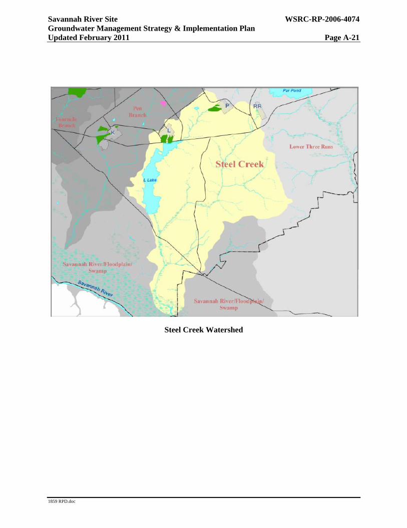
Steel Creek Watershed

Savannah River Site WSRC-RP-2006-4074 Groundwater Management Strategy & Implementation Plan Updated February 2011 Page A-22
1859 RPD.doc
Watershed Description
The headwaters of Steel Creek originate near P-Reactor, southwest of Par Pond. Steel Creek flows southwesterly about two miles before it enters the headwater of L Lake. L Lake is four miles long with an area of about 1,034 acres. Flow from the outfall of L Lake dam travels about three miles before entering the Savannah River Swamp and another two miles before entering the Savannah River. Steel Creek has received thermal discharges and increased flow from reactor operations that produced an extensive delta where Steel Creek enters the Savannah River Floodplain Swamp. Meyers Branch, the main tributary of Steel Creek, flows approximately six miles before entering Steel Creek. Meyers Branch is relatively undisturbed by SRS operations. The total area drained by the Steel Creek and Meyers Branch system is about 35 square miles and includes portions of P and L Areas.
Groundwater Contamination Areas
P and L — All SRS reactor areas were constructed with similar facilities, and similar processes were used during their operations. The areas where the reactors are located also contain former disposal sites such as burning/rubble pits and basins to dispose of hazardous substances. Principal contaminants in the reactor areas are cesium-137, strontium, tritium, spent organic chemicals, and low-level radioactive debris. Monitoring wells indicate the presence of tritium and VOCs in the groundwater.
Projects
Groundwater Contamination Area
Plume Project Technology
P PBRP P Area Burning/Rubble Pit MNA
PAGW P Area Reactor Groundwater Characterization in progress
L LASG L Area Southern Groundwater MNA
LBRP L Area Burning/Rubble Pit MNA
Remediation
The P Area Operable Unit Early Action Statement of Basis/Proposed Plan has been approved and contains commitments to remediate two vadose zone areas impacted with solvents. Remediation will include chemical oxidation and SVE to remove sources to the P Area Groundwater (PAGW) Operable Unit. In addition, treatability studies evaluating enhanced bioremediation techniques are underway at PAGWOU.

Savannah River Site WSRC-RP-2006-4074 Groundwater Management Strategy & Implementation Plan Updated February 2011 Page A-23
1859 RPD.doc
Accomplishments
The Treatability Study Work Plan for Edible Oil and MicroCED Deployment for Enhanced VOC Attenuation for P Area was approved by EPA and SCDHEC in April 2010.
DOE, EPA, and SCDHEC agreed to pursue a No Action ROD at L Area Northern Groundwater. The Statement of Basis/Proposed Plan was submitted to EPA and SCDHEC on March 30, 2010. The No Action ROD is expected to be issued in October 2011.
The LBRP 2009 Annual Groundwater Data Summary Report was submitted to EPA and SCDHEC on June 28, 2010. The data indicated that carbon tetrachloride concentration increased during 2009 from concentrations in 2008.
The PBRP 2009 Annual Groundwater Data Summary Report was submitted to EPA and SCDHEC on June 28, 2010. Sampling was changed from semi-annually to annually. Analytical results indicated that 1,2-dichloroethylene, PCE, and TCE concentrations decreased in 2009 from the values in 2008, resulting in only one MCL exceedance at well PRP6.

Savannah River Site WSRC-RP-2006-4074 Groundwater Management Strategy & Implementation Plan Updated February 2011 Page A-24
1859 RPD.doc
Lower Three Runs Watershed

Savannah River Site WSRC-RP-2006-4074 Groundwater Management Strategy & Implementation Plan Updated February 2011 Page A-25
1859 RPD.doc
Lower Three Runs Watershed
Watershed Description
The LTR Watershed is located on the eastern portion of SRS and lies partially within the SRS boundary. The Lower Three Runs stream is the principal surface water body within the watershed and is located entirely on SRS property, including the narrow corridor that extends from Patterson Mill to the confluence with the Savannah River. The watershed, which drains about 178 square miles, includes R Area, a portion of P Area, ecological laboratories and various ACP operable units. Industrial facilities located outside the eastern SRS boundary are also located within the LTR Watershed. A mainstream impoundment, Par Pond, was constructed along with several other retaining ponds on the headwaters of Lower Three Runs to receive reactor effluent.
Groundwater Contamination Areas
R — All SRS reactor areas were constructed with similar facilities, and similar processes were used during their operations. The areas where the reactors are located also contain former disposal sites such as burning/rubble pits and basins to dispose of hazardous substances. Principal contaminants in the reactor areas are cesium-137, strontium, tritium, spent organic

Savannah River Site WSRC-RP-2006-4074 Groundwater Management Strategy & Implementation Plan Updated February 2011 Page A-26
1859 RPD.doc
chemicals, and low-level radioactive debris. Monitoring wells indicate the presence of tritium and VOCs in the groundwater.
Projects
Groundwater Contamination Area
Plume Project Technology
RSB R Area Reactor Seepage Basin MNA R
RAGW R Area Groundwater MNA (Proposed)
Remediation
The RAGW Operable Unit was integrated into the R Area Operable Unit based on Core Team agreement. There are no identified sources of contamination impacting RAGW Operable Unit. MNA has been selected as a final remedy.
Accomplishments
The first MZ Monitoring Report for the groundwater associated with the R Area Reactor Seepage Basins was submitted to EPA and SCDHEC on August 5, 2008. The report indicates that the established mixing zone is being met. The second report was submitted in August 2010, with the same conclusion.
The Statement of Basis/Proposed Plan for the R Area Operable Unit, which proposed land use controls and MNA for the RAGW, was submitted to EPA and SCHDEC in January 2010. The MNA will consist of monitoring the four plumes in the upper three aquifers (A/AA, TX, and Middle aquifer zone) from the point of origin to the point of discharge or downgradient extent for VOCs and tritium. The ROD is expected to be issued in May 2011.
Cone Penetrometer Testing was completed to support monitoring well installations for R Area Operable Unit plume definition purposes, and eight monitoring wells were installed in support of the proposed monitored natural attenuation remedy to address groundwater contamination.
Savannah River Site WSRC-RP-2006-4074 Groundwater Management Strategy & Implementation Plan Updated February 2011 Page A-27
1859 RPD.doc
Savannah River Floodplain Swamp Watershed

Savannah River Site WSRC-RP-2006-4074 Groundwater Management Strategy & Implementation Plan Updated February 2011 Page A-28
1859 RPD.doc
Savannah River Floodplain Swamp Watershed
Watershed Description
The SRFPS Watershed drains about 10,574 square miles, including western South Carolina, eastern Georgia, and a small portion of southwestern North Carolina. Approximately 31% of the watershed area is located in the Coastal Plain and includes Augusta, SRS, and Savannah to the Atlantic Ocean. The SRFPS Integrator Operable Unit includes the 100-year floodplain (including the Savannah River Swamp) and any continuous wetlands, including the Savannah River adjacent and downgradient of SRS. This area encompasses approximately 45 miles from the northern boundary of SRS above UTR southward to the U.S. Highway 301 Bridge. The five major SRS streams feed into the SRFPS (UTR, FMB, Pen Branch, Steel Creek, and LTR). SRFPS Watershed includes portions of A/M Area, D Area, and TNX.
Groundwater Contamination Areas
D — D Area was used beginning in the mid-1950s to dispose of coal ash, oil, chemicals, and construction debris. A power station is operating in D Area. Sampling results indicate that soil and groundwater in the area are contaminated by metals, tritium, and solvents.

Savannah River Site WSRC-RP-2006-4074 Groundwater Management Strategy & Implementation Plan Updated February 2011 Page A-29
1859 RPD.doc
T — T Area was operated from the mid-1950s through the mid-1980s to conduct pilot tests to support SRS operations. The principal contaminants are mercury, thorium, uranium, radium, and chlorinated solvents. Because of its location near the Savannah River, the T Area was the first Area Completion in 2006.
Projects
Groundwater Contamination Area
Plume Project Technology
T TNX TNX Groundwater Edible Oil, MNA
D DOSB D Area Oil Seepage Basin MNA
DAGW D Area Groundwater Characterization starts FY2018
Remediation
T Area
T Area has a small persistent TCE/PCE plume that had been remediated with Pump & Treat (air stripper) since 1996 but reached a point of diminishing effectiveness. The new remediation strategy is to use Edible Oil Injection to sequester and biologically destroy the VOCs. Neat Edible Oil is injected to sequester the VOCs (vadose zone source), and Edible Oil emulsion (food source) is injected to promote microbial activity and reduce conditions in groundwater (reductive dechlorination). If effective, the remedial strategy could be implemented by 2012. Implementation of the new strategy will result in elimination of the air stripper.
Accomplishments
The 2009 Comprehensive TNX Area Annual Groundwater and Effectiveness Monitoring Strategy Report and the Interim Report - Year Two for the Treatability Study for Edible Oil Deployment for Enhanced VOC attenuation for T Area were submitted to EPA and SCDHEC on June 30, 2010.
The temporary shutdown of the T-1 Airstripper was approved to accommodate the completion the treatability study. Based on the results of the treatability study to date, it is believed that the groundwater conditions will support a passive MNA remedy. If this is the case, both an MNA application and an Explanation of Significant Difference to the T Area Record of Decision will be submitted following the 2010 Comprehensive TNX Area Annual Groundwater and Effectiveness Monitoring Strategy Report approval.

Savannah River Site WSRC-RP-2006-4074 Groundwater Management Strategy & Implementation Plan Updated February 2011 Page A-30
1859 RPD.doc
This page intentionally left blank