sathyabama university school of mechanical engineering sme1202 fluid ... · fluid pressure fluid...
TRANSCRIPT
SATHYABAMA UNIVERSITY School of Mechanical Engineering SME1202 Fluid Mechanics and Machinery
Page | 1
UNTT 1 FLUID PROPERTIES
Fluid Properties: Density, Specific weight ,Specific gravity, Viscosity ,Surface tension, Capillarity,
Vapour pressure and compressibility.
Fluid Statics: Hydrostatic Law - Pressure Variation in static fluid- Hydrostatic force on submerged
plane surfaces - Location of hydrostatic force.
Manometers- Simple U tube and differential manometers.
Buoyancy - Metacentric height; determination of stability of floating bodies and submerged bodies.
Fluids: Substances capable of flowing are known as fluids. Flow is the continuous deformation of
substances under the action of shear stresses.
Fluids have no definite shape of their own, but confirm to the shape of the containing vessel. Fluids
include liquids and gases.
Fluid Mechanics:
Fluid mechanics is the branch of science that deals with the behavior of fluids at rest as well as in
motion. Thus,it deals with the static, kinematics and dynamic aspects of fluids.
The study of fluids at rest is called fluid statics. The study of fluids in motion, where pressure
forces are not considered, is called fluid kinematics and if the pressure forces are also considered for
the fluids in motion, that branch of science is called fluid dynamics.
Fluid Properties:
1.Density (or )Mass Density:
Density or mass density of a fluid is defined as the ratio of the mass of the fluid to its volume.
Thus, Mass per unit volume of a fluid is called density.
fluidofVolume
fluidofMassdensityMass ,
S.I unit of density is kg/m3.
The value of density for water is 1000 kg/m3.
2.Specific weight (or) Weight Density (w ):
Specific weight or weight density of a fluid is the ratio between the weight of a fluid to its
volume.
The weight per unit volume of a fluid is called specific weight or weight density.
fluidofVolume
fluidofWeightdensityWeight
fluidofVolume
gXfluidofMassw
gw
S.I unit of specific weight is N/m3.
The value of specific weight or weight density of water is 9810N/m3 or 9.81 kN/m³.
3. Specific Volume (ʋ):
Specific volume of a fluid is defined as the volume of a fluid occupied by unit mass.
Volume per unit mass of a fluid is called Specific volume.

SATHYABAMA UNIVERSITY School of Mechanical Engineering SME1202 Fluid Mechanics and Machinery
Page | 2
1
fluidofMass
fluidaofVolumevolumeSpecific
Thus specific volume is the reciprocal of mass density. S.I unit: m3/kg.
4. Specific Gravity (s):
Specific gravity is defined as the ratio of the specific weight of a fluid to the specific weight
of a standard fluid.
waterof weightSpecific
liquidof weightSpecificgravitySpecific
Specific gravity is also equal to Relative density. Relative density = 𝐷𝑒𝑛𝑠𝑖𝑡𝑦 𝑜𝑓 𝑙𝑖𝑞𝑢𝑖𝑑
𝐷𝑒𝑛𝑠𝑖𝑡𝑦 𝑜𝑓 𝑤𝑎𝑡𝑒𝑟
5. Viscosity:
Viscosity is defined as the property of a fluid which offers resistance to the movement of one
layer of fluid over adjacent layer of the fluid.
When two layers of a fluid, at distance ‘dy’ apart, move
one over the other at different velocities, say u and u+du as
shown in figure. The viscosity together with relative velocity
causes a shear stress acting between the fluid layers.
The top layer causes a shear stress on the adjacent lower layer
while the lower layer causes a shear stress on the adjacent top
layer.
This shear stress is proportional to the rate of change of velocity
with respect to y.
dy
du
or dy
du
where, μ is the constant of proportionality and is known as the co-efficient of dynamic viscosity or
viscosity and dy
du represents the rate of shear strain or rate of shear deformation or velocity gradient.
dy
du
Thus the viscosity is also defined as the shear stress required to produce unit rate of shear
strain.
S.I unit: Ns/m². It is still expressed in poise (P) as well as centipoises (cP).
;
Kinematic Viscosity(ν):
It is defined as the ratio between the dynamic viscosity and density of the fluid
ν =.𝐷𝑦𝑛𝑎𝑚𝑖𝑐 𝑣𝑖𝑠𝑐𝑜𝑠𝑖𝑡𝑦
𝐷𝑒𝑛𝑠𝑖𝑡𝑦 =
𝜇
𝜌
SI unit: m2/s; CGS unit ‘stoke’. 1 stoke = 1 cm2/ sec = 10-4 m2/s

SATHYABAMA UNIVERSITY School of Mechanical Engineering SME1202 Fluid Mechanics and Machinery
Page | 3
Newton's Law of Viscosity:
It states that the shear stress (τ) on a fluid element layer is directly proportional to the rate of shear
strain. The constant of proportionality is called the co-efficient of viscosity.
dy
du
6.Compressibility:
Compressibility is the reciprocal of the bulk modulus of elasticity, K, which is defined as the
ratio of compressive stress to volumetric strain.
Compression of fluids gives rise to pressure with the decrease in volume.
If dv is the decrease in volume and dp is the increase in pressure, Volumetric Strain = V
dV
(- ve sign indicate the volume decreases with increase of pressure)
Bulk modulus, K = StrainVolumetric
pressureofIncrease
=
V
dV
dp
Compressibility = K
1
7.Surface tension:
Surface tension is defined as the tensile force acting on the surface of a liquid in contact with a
gas or on the surface between two immiscible liquids such that the contact surface behaves like a
membrane under tension.
Surface Tension on Liquid Droplet:
Consider a small spherical droplet of a liquid of diameter ‘d’. On the entire surface of the droplet,
the tensile force due to surface tension will be acting.
Let σ = Surface tension of the liquid
p = Pressure intensity inside the droplet (in excess of the outside pressure intensity)
d = Dia. of droplet.
Let the droplet is cut into two halves. The forces acting on one half will be
i) Tensile force (FT)due to surface tension acting around the circumference of the cut portion as
shown in fig. and this is equal to = σ x Circumference = σ x π d
ii) Pressure force (Fp) on the area 𝜋𝑑2
4 is = p x
𝜋𝑑2
4 as shown in the figure.
These two forces are equal under equilibrium conditions. i.e.,
p x 𝜋𝑑2
4 = σ x π d

SATHYABAMA UNIVERSITY School of Mechanical Engineering SME1202 Fluid Mechanics and Machinery
Page | 4
Therefore, 𝑝 = 4𝜎
𝑑
Surface Tension on a Hollow Bubble:
A hollow bubble like a soap bubble in air has two surfaces in contact with air, one inside and other
outside. Thus two surfaces arc subjected to surface tension.
In that case,
p x 𝜋𝑑2
4 = 2 x (σ x π d)
Therefore, 𝑝 = 8𝜎
𝑑
8. Capillarity:
Capillarity is defined as a phenomenon of rise or fall of a liquid surface in a small tube relative to the
adjacent general level of liquid when the tube is held vertically in the liquid.
The rise of liquid surface is known as capillary rise while the fall of the liquid surface is known as
capillary depression. It is expressed in terms of cm or mm of liquid. Its value depends upon the
specific weight of the liquid, diameter of the tube and surface tension of the liquid.
Expression for Capillary Rise:
Consider a glass tube of small diameter ‘d' opened at both ends and is inserted in a liquid. The liquid
will rise in the lube above the level of the liquid.
Let, h = height of the liquid in the tube. Under
a state of equilibrium,
the weight of liquid of height h is balanced by
the force at the surface of
the liquid in the tube. But the force at the
surface of the liquid in the tube
is due to surface tension.
Let, σ = Surface tension of liquid
θ= Angle of contact between liquid and glass
lube.
The weight of liquid of height ‘h’ in the tube = (Area of tube x h) x ρ x g
where, ρ = density of liquid
Vertical component of the surface tensile force
= σ x Circumference x cos θ
= σ x πd x cos θ
Weight of liquid of height ‘h’ in the tube = Vertical component of the surface tensile force
or h = 𝟒𝝈 𝒄𝒐𝒔ɵ
𝒘 𝒅
9.Vapour pressure:
Vapour pressure is the pressure of the vapor over a liquid which is confined in a closed vessel at
equilibrium.

SATHYABAMA UNIVERSITY School of Mechanical Engineering SME1202 Fluid Mechanics and Machinery
Page | 5
Vapour pressure increases with temperature.All liquids exhibit this phenomenon.
Types of fluid:
i. Ideal Fluid: A fluid, which is
incompressible and is having no viscosity, is
known as an ideal fluid. Ideal fluid is only an
imaginary fluid as all the fluids, which exist,
have some viscosity.
ii. Real Fluid: A fluid, which possesses
viscosity, is known as real fluid. All the fluids,
are real fluids in actual practice.
iii. Newtonian Fluid: A real fluid, in which the shear stress is directly proportional to the rate of
shear strain (or) velocity gradient, is known as a Newtonian fluid.
iv. Non-Newtonian Fluid: A real fluid, in which the shear stress is not proportional to the rate of
shear strain (or) velocity gradient, is known as a Non-Newtonian fluid.
v. Ideal Plastic Fluid: A fluid, in which shear stress is more than the yield value and shear stress is
proportional to the rate of shear strain (or) velocity gradient, is known as ideal plastic fluid
Fluid Pressure
Fluid pressure is the force exerted by the fluid per unit area.
Fluid pressure or Intensity of pressure or pressure, 𝒑 =𝑭
𝑨
Fluids exert pressure on surfaces with which they are in contact.
Fluid pressure is transmitted with equal intensity in all directions and acts normal to any plane.
In the same horizontal plane the pressure intensities in a liquid are equal.
S.I unit of fluid pressure are N/m² or Pa, where 1 N/m² = 1 Pa.
Many other pressure units are commonly used:
1 bar = 105 N/m²
1 atmosphere = 101325 N/m² = 101.325kN/m²
Some Terms commonly used in static pressure analysis include:
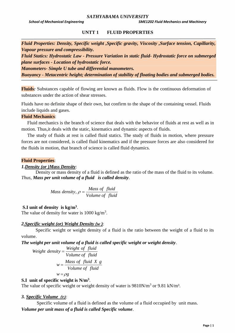
Pressure Head: The pressure intensity exerted at the base of a column of homogenous fluid of a
given height in metres. Vacuum: A perfect vacuum is a completely empty space in which, therefore the pressure is zero.
Atmospheric Pressure: The pressure at the surface of the earth exerted by the head of air above the
surface.
At sea level the atmospheric pressure = 101.325 kN/m² = 101325 N/m² or pa
= 1.01325 bar
= 760 mm of mercury
= 10.336 m of water
Atmospheric pressure is measured by a device called a barometer; thus, the atmospheric pressure is
often referred to as the barometric pressure.
Gauge Pressure: The pressure measured by a pressure gauge above or below atmospheric pressure.
Vacuum pressure: The gauge pressure less than atmospheric is called Vacuum pressure or negative
pressure.
Absolute Pressure: The pressure measured above absolute zero or vacuum.
SATHYABAMA UNIVERSITY School of Mechanical Engineering SME1202 Fluid Mechanics and Machinery
Page | 6
Absolute Pressure = Atmospheric Pressure + Gauge Pressure
Absolute Pressure = Atmospheric Pressure – Vacuum pressure
Atmospheric, Gauge & Absolute pressure
Hydrostatic law
The hydrostatic law is a principle that identifies the amount of pressure exerted at a
specific point in a given area of fluid.
It states that, “The rate of increase of pressure in the vertically downward direction, at a point
in a static fluid, must be equal to the specific weight of the fluid.”
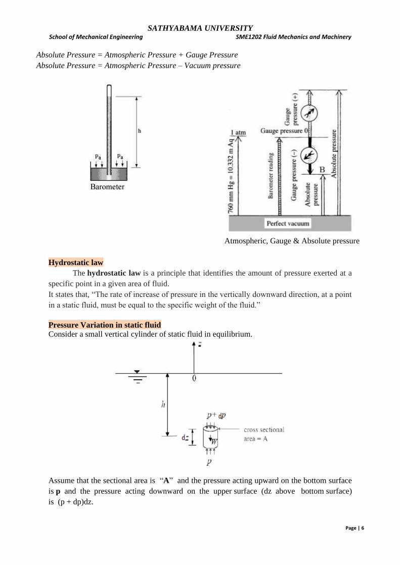
Pressure Variation in static fluid
Consider a small vertical cylinder of static fluid in equilibrium.
Assume that the sectional area is “A” and the pressure acting upward on the bottom surface
is p and the pressure acting downward on the upper surface (dz above bottom surface)
is (p + dp)dz.
SATHYABAMA UNIVERSITY School of Mechanical Engineering SME1202 Fluid Mechanics and Machinery
Page | 7
Let the free surface of the fluid be the origin, i.e., Z = 0. Then the pressure variation at a
depth Z = - h below the free surface is governed by
(p + dp) A + W = pA
dpA + ρgAdz = 0 [W= w x volume = ρg Adz]
dp = -ρgdz 𝑑𝑝
𝑑𝑧 = - ρg = - w
Therefore, the hydrostatic pressure increases linearly with depth at the rate of the specific weight,
w = ρg of the fluid.
If fluid is homogeneous, ρ is constant.
By simply integrating the above equation,
ʃdp = - ʃρg dz => p = - ρg Z + C
Where C is constant of integration.
When z = 0 (on the free surface), p = C = po = the atmospheric pressure.
Hence, p = - ρgZ + po
Pressure given by this equation is called ABSOLUTE PRESSURE, i.e., measured above perfect
vacuum.
However, it is more convenient to measure the pressure as gauge pressure by setting atmospheric
pressure as datum pressure. By setting po = 0,
p = -ρgz+0 = -ρgz = ρgh
p = wh
The equation derived above shows that when the density is constant, the pressure in a liquid at rest
increases linearly with depth from the free surface.
The above expression can be rearranged as, h = 𝒑
𝒘
Here, h is known as pressure head or simply head of fluid.
In fluid mechanics, fluid pressure is usually expressed in height of fluids or head of fluids.
Hydrostatic force
Hydrostatic pressure is the force exerted by a static fluid on a plane surface, when the static
fluid comes in contact with the surface. This force will act normal to the surface. It is also known as
Total Pressure.
The point of application of the hydrostatic or total pressure on the surface is known as Centre of
pressure.
The vertical distance between the free surface of fluid and the centre of pressure is called depth of
centre of pressure or location of hydrostatic force.
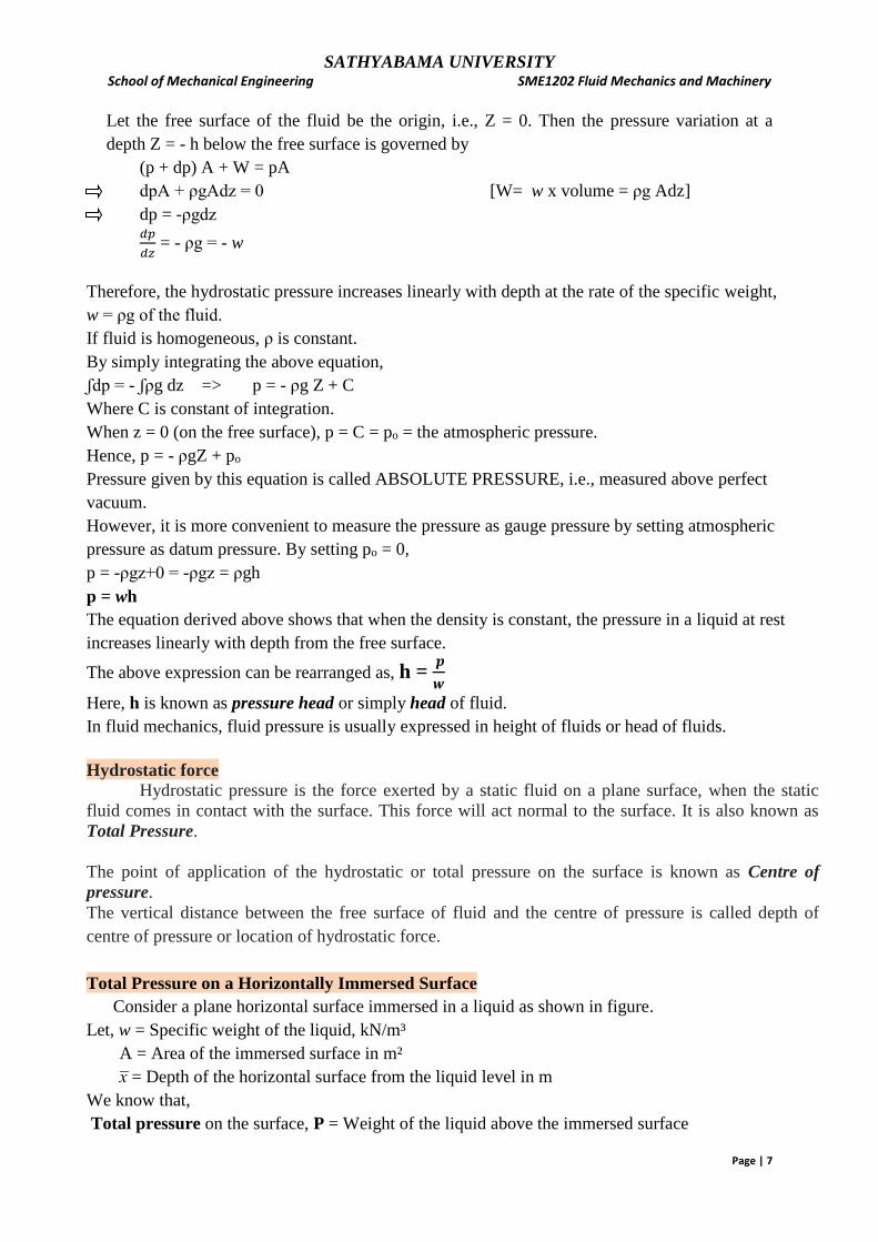
Total Pressure on a Horizontally Immersed Surface
Consider a plane horizontal surface immersed in a liquid as shown in figure.
Let, w = Specific weight of the liquid, kN/m³
A = Area of the immersed surface in m²
x = Depth of the horizontal surface from the liquid level in m
We know that,
Total pressure on the surface, P = Weight of the liquid above the immersed surface

SATHYABAMA UNIVERSITY School of Mechanical Engineering SME1202 Fluid Mechanics and Machinery
Page | 8
P = Specific weight of liquid x Volume of liquid
= Specific weight of liquid x Area of surface x Depth of liquid
P = wA x kN
Total Pressure and depth of centre of pressure on a Vertically Immersed Surface
Consider an irregular plane vertical surface immersed in a liquid as shown in figure .
Let,
w = Specific weight of liquid
A = Total area of the immersed surface
x = Depth of the center of gravity of the immersed surface from the liquid surface
Now. consider a strip of width ‘b’, thickness ‘dx’ and at a depth x from the free surface of the liquid
Moment of pressure on the strip about the free surface of liquid = x b dx X x = x² b dx
Total moment on the entire plane immersed surface = ∫ x² b dx
M = ∫ 𝑥² 𝑏 𝑑𝑥
But, ∫ 𝑥² 𝑏 𝑑𝑥 = second moment of area about free liquid surface = Io
therefore, M = Io
Io = IG + A x², according to parallel axis theorem.
Therefore, M = (IG + A x²) ------------------------------ (1)
Also M = P x h = Ax x h ---------------------------------- (2)
Since equations 1 & 2 are equal,
SATHYABAMA UNIVERSITY School of Mechanical Engineering SME1202 Fluid Mechanics and Machinery
Page | 9
Ax x h = (IG + A x²)
Depth of centre of pressure, h = (IG + A x²) / Ax
Therefore, h = x + 𝐼𝐺
A𝑥
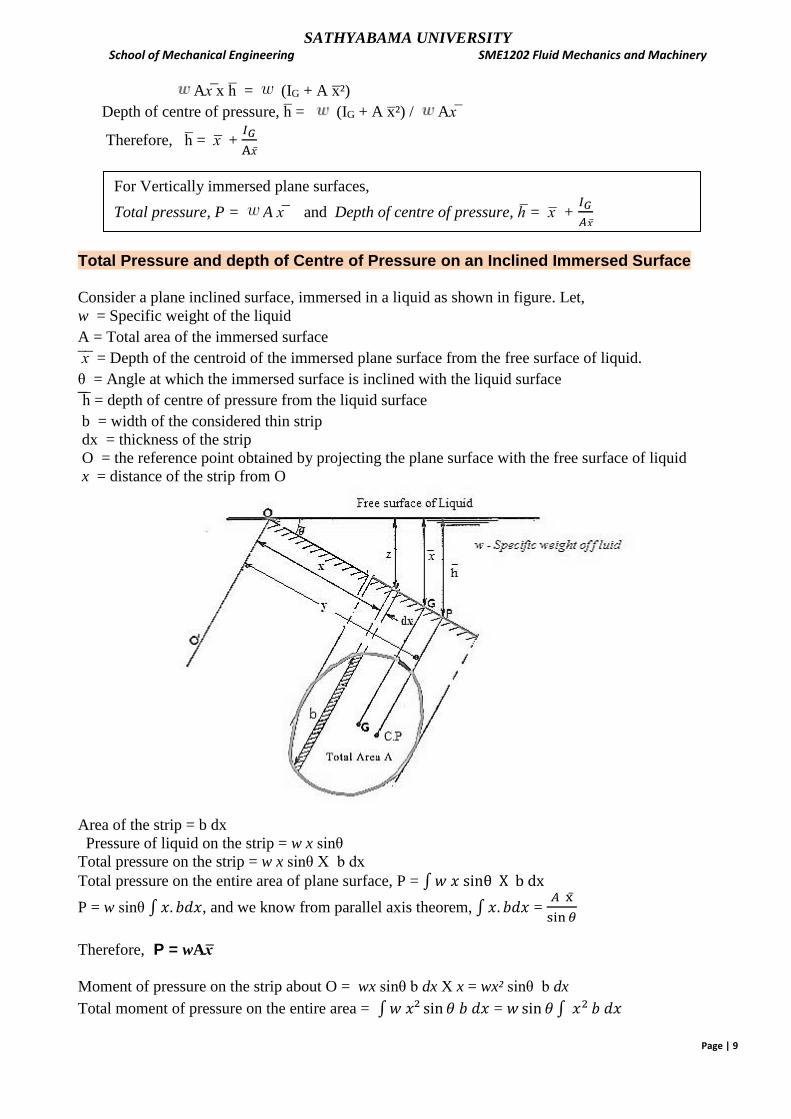
Total Pressure and depth of Centre of Pressure on an Inclined Immersed Surface
Consider a plane inclined surface, immersed in a liquid as shown in figure. Let,
w = Specific weight of the liquid
A = Total area of the immersed surface
x = Depth of the centroid of the immersed plane surface from the free surface of liquid.
θ = Angle at which the immersed surface is inclined with the liquid surface
h = depth of centre of pressure from the liquid surface
b = width of the considered thin strip
dx = thickness of the strip
O = the reference point obtained by projecting the plane surface with the free surface of liquid
x = distance of the strip from O
Area of the strip = b dx
Pressure of liquid on the strip = w x sinθ
Total pressure on the strip = w x sinθ X b dx
Total pressure on the entire area of plane surface, P = ∫𝑤 𝑥 sinθ X b dx
P = w sinθ ∫ 𝑥. 𝑏𝑑𝑥, and we know from parallel axis theorem, ∫ 𝑥. 𝑏𝑑𝑥 = 𝐴 x
sin 𝜃
Therefore, P = wAx Moment of pressure on the strip about O = wx sinθ b dx X x = wx² sinθ b dx
Total moment of pressure on the entire area = ∫𝑤 𝑥² sin 𝜃 𝑏 𝑑𝑥 = 𝑤 sin 𝜃 ∫ 𝑥2 𝑏 𝑑𝑥
For Vertically immersed plane surfaces,
Total pressure, P = A x and Depth of centre of pressure, h = x + 𝐼𝐺
𝐴𝑥
SATHYABAMA UNIVERSITY School of Mechanical Engineering SME1202 Fluid Mechanics and Machinery
Page | 10
But, ∫ 𝑥2 b dx = second moment of area about O-Oʹ = Io
oo o M.I = 𝑤 sin 𝜃 Io --------------------------------------- (1)
but, Io = IG + A 𝑥 ²
sin² 𝜃
Also,M.I = P.y; and y = h
𝑠𝑖𝑛𝜃
ooo M.I = P.
h
𝑠𝑖𝑛𝜃 -----------------------------------------------(2)
Equating 1 & 2, P.h = 𝑤 sin² 𝜃 Io
P.h = 𝑤 sin² 𝜃 [IG + A 𝑥 ²
sin² 𝜃]
ooo h = 𝑤 sin² 𝜃 [IG + A x²]/ P =
𝑤sin² 𝜃 [IG + A 𝑥 ²
sin²𝜃]
𝑤𝐴x =
𝐼𝐺
𝐴
sin² 𝜃
x + x
or h = x + 𝐼𝐺 sin² 𝜃
𝐴x
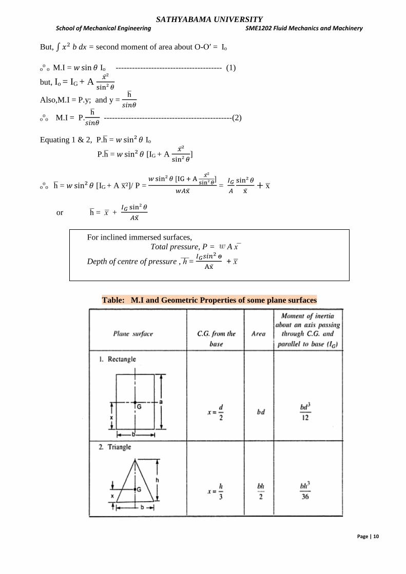
Table: M.I and Geometric Properties of some plane surfaces
For inclined immersed surfaces,
Total pressure, P = A x
Depth of centre of pressure , h = 𝐼𝐺𝑠𝑖𝑛
2 ɵ
Ax + x
SATHYABAMA UNIVERSITY School of Mechanical Engineering SME1202 Fluid Mechanics and Machinery
Page | 11
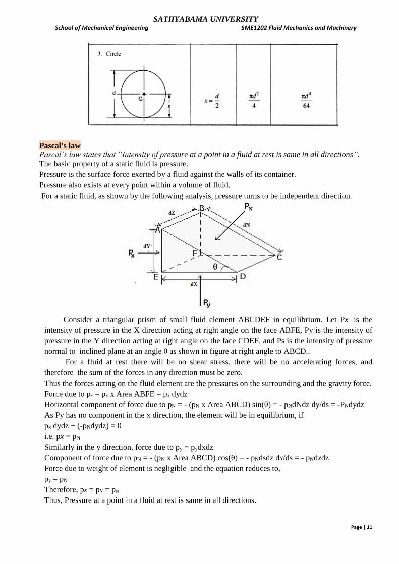
Pascal's law
Pascal’s law states that “Intensity of pressure at a point in a fluid at rest is same in all directions”. The basic property of a static fluid is pressure.
Pressure is the surface force exerted by a fluid against the walls of its container.
Pressure also exists at every point within a volume of fluid.
For a static fluid, as shown by the following analysis, pressure turns to be independent direction.
Consider a triangular prism of small fluid element ABCDEF in equilibrium. Let Px is the
intensity of pressure in the X direction acting at right angle on the face ABFE, Py is the intensity of
pressure in the Y direction acting at right angle on the face CDEF, and Ps is the intensity of pressure
normal to inclined plane at an angle θ as shown in figure at right angle to ABCD..
For a fluid at rest there will be no shear stress, there will be no accelerating forces, and
therefore the sum of the forces in any direction must be zero.
Thus the forces acting on the fluid element are the pressures on the surrounding and the gravity force.
Force due to px = px x Area ABFE = px dydz
Horizontal component of force due to pN = - (pN x Area ABCD) sin(θ) = - pNdNdz dy/ds = -PNdydz
As Py has no component in the x direction, the element will be in equilibrium, if
px dydz + (-pNdydz) = 0
i.e. px = pN
Similarly in the y direction, force due to py = pydxdz
Component of force due to pN = - (pN x Area ABCD) cos(θ) = - pNdsdz dx/ds = - pNdxdz
Force due to weight of element is negligible and the equation reduces to,
py = pN
Therefore, px = py = pN
Thus, Pressure at a point in a fluid at rest is same in all directions.

SATHYABAMA UNIVERSITY School of Mechanical Engineering SME1202 Fluid Mechanics and Machinery
Page | 12
Manometers:
Manometer is an instrument for measuring the pressure of a fluid, consisting of a tube filled with a
heavier gauging liquid, the level of the liquid being determined by the fluid pressure and the height
of the liquid being indicated on a scale. A U-tube manometer consists of a glass tube bent in U-Shape,
one end of which is connected to gauge point and the other end is exposed to atmosphere.
Manometric liquids:
1. Manometric liquids should neither mix nor have any chemical reaction with the liquid whose
pressure intensity is to be measured.
2. It should not undergo any thermal variation.
3. Manometric liquid should have very low vapour pressure.
4. Manometric liquid should have pressure sensitivity depending upon the magnitude of pressure
to be measured and accuracy requirement.
Convert all vertical columns of liquids to meters of water by multiplying them by corresponding
specify gravity.
To write the manometric equation:
1. Convert all given pressure to meters of water and assume unknown pressure in meters of waters.
2. Proceeding from one end towards the other the following points must be considered.
Any horizontal movement inside the same liquid will not cause change in pressure.
Vertically downward movement causes increase in pressure and upward motion cause decrease in
pressure.
Convert all vertical columns of liquids to meters of water by multiplying them by corresponding specify
gravity.
Take atmospheric pressure as zero (gauge pressure computation).
3. Solve for the unknown quantity and convert it into the required unit.
Piezometer:The simplest form of manometer is the piezometer. The height of the fluid in the tube
gives the difference between pressure in the pipe and atmosphere.
The piezometer is only useful when the pressure to be measured is greater than
atmospheric (otherwise) air would be sucked back into system.
ℎ𝐴 = h .s1 m of water
pA = w.hA kN/m2
where, w = specific weight of fluid in kN/m³
Simple U tube manometer:
A very common form of manometer is the U tube manometer. In
this version one of the tubes is open to the atmosphere.
Manometer equation
Let the lower level of manometer liquid be the datum

SATHYABAMA UNIVERSITY School of Mechanical Engineering SME1202 Fluid Mechanics and Machinery
Page | 13
Pressure of liquid above datum in the left limb = Pressure of liquid above datum in the right limb
ℎ𝐴 + h1.s1 = h2. s2 m of water
ℎ𝐴 = h2. s2 - h1.s1 m of water.
PA = w.hA kN/m2
where , w = specific weight of water.
Differential U-tube manometer
Let,
A and B are the two pipes carrying liquids of specific gravity s1 and s3 & s2 = specific gravity of
manometer liquid.
h1 = height of pipe A liquid in left limb & h2 = height of manometer liquid in right limb above datum;
h3 = height of pipe B liquid right limb as shown in figure.
Let, 𝑝𝐴 and 𝑝𝐵 be the pressure of liquids in the corresponding pipes A and B.
If 𝑝𝐴 > 𝑝𝐵 , then the manometer equation is,
𝑝𝐴 + 𝑤1ℎ1= 𝑝𝐵 + 𝑤2ℎ2+ 𝑤3ℎ3
𝑝𝐴 − 𝑝𝐵 = 𝑤2ℎ2 + 𝑤3ℎ3 − 𝑤1ℎ1 N/ m2
Dividing both sides by specific weight of water, w
𝑝𝐴−𝑝𝐵
𝑤=
𝑤2ℎ2
𝑤+
𝑤3ℎ3
𝑤−
𝑤1ℎ1
𝑤 m of water
ℎ𝐴 − ℎ𝐵 = 𝑠2ℎ2 + 𝑠3ℎ3 − 𝑠1ℎ1 m of water [ ᶱ ᶱᶱ 𝑝
𝑤 = pressure head ‘h’, in m of water &
𝑤𝑙
𝑤𝒘 = sl (sp.gravity of liquid)]
= [𝑠2ℎ2 + 𝑠3ℎ3 − 𝑠1ℎ1 ] x 9.81 kN/m²
Buoyant force: The upward force exerted by a liquid on a body when the body is immersed in the
liquid is known as buoyancy or buoyant force.
The point through which force of buoyancy is supposed to act is called centre of buoyancy.
The buoyant force acting on a body is equal to the weight of the liquid displaced by the body.
For a fluid with constant density, the buoyant force is independent of the distance of the body from the
free surface. It is also independent of the density of the solid body.

SATHYABAMA UNIVERSITY School of Mechanical Engineering SME1202 Fluid Mechanics and Machinery
Page | 14
Archimedes principle: The buoyant force acting on a body immersed in a fluid is equal to the weight
of the fluid displaced by the body, and it acts upward through the centroid of the displaced volume.
For floating bodies, the weight of the entire body must be equal to the buoyant force, which is the
weight of the fluid whose volume is equal to the volume of the submerged portion of the floating body.
ρ - density of body; ρf – density of fluid
A solid body dropped into a fluid will sink, float,
or remain at rest at any point in the fluid,
depending on its average density relative to the
density of the fluid.
Stability of Immersed and Floating Bodies
A floating body possesses vertical stability, while an immersed neutrally buoyant body is neutrally
stable since it does not return to its original position after a disturbance.
An immersed neutrally buoyant body is (a) stable if the center of gravity G is directly below the center of
buoyancy B of the body, (b) neutrally stable if G and B are coincident, and (c) unstable if G is directly above B.
Stability of floating bodies: A floating body is stable if the body is bottom-heavy and thus the center
of gravity G is below the centroid B of the body, or if the metacentre M is above point G. However,
the body is unstable if point M is below point G.

SATHYABAMA UNIVERSITY School of Mechanical Engineering SME1202 Fluid Mechanics and Machinery
Page | 15
Metacentre: The point about which a body starts oscillating when the body is tilted is known meta-
centre.
Metacentric height GM: The distance between the center of gravity G and the metacenter M is
known as Meta centric height. It is the point of intersection of line of action of buoyant force with the
line passing through centre of gravity, when the body is slightly tilted.
The length of the metacentric height GM above G is a measure of the stability: If the metacentric
height increases, then the floating body will be more..
The meta-centric height (GM) is.given by, GM = 𝐼
V - BG
Where, I = Moment of Inertia of the floating body (in plan) at water surface about the axis Y- Y
V = Volume of ihe body sub merged in water
BG = Distance between centre of gravity and centre of buoyancy.
Conditions of equilibrium of a floating and submerged body are :
Equilibrium Floating Body Sub-merged Body
(i) Stable Equilibrium
(a) Unstable Equilibrium
(Hi) Neutral Equilibrium
M is above G
M is below G
Af and G coincide
B is above G
B is below G
B and G coincide
The value of meta-cenlric height GM, experimentally is given as GM = 𝑤1 𝑥
𝑊 tan𝜃
Where
w1 = Movable weight
x = Distance through which w1 is moved
W = Weight of the ship or floating body including w1
θ = Angle through the ship or floating body is tilted due to the movement of w1
Problems
1. 5000 litres of an oil weighs 45 kN. Find its Specific weight, mass density and relative density.
Given: To find:
Volume, V = 5000 lit = 5000/1000 = 5 m³ i)Density,ρ
Weight, W= 45 kN = 45000 N ii)relative density, s
Specific Weight, w = W/V = 45000 / 5 = 9000 N/m³ = 9 kN/m³

SATHYABAMA UNIVERSITY School of Mechanical Engineering SME1202 Fluid Mechanics and Machinery
Page | 16
Specific Weight, w = ρg
Mass density, ρ = w/g = 9000/ 9.81 = 917.43 kg/m³
Relative density = Density of oil/density of water = 917.43/ 1000 = 0.917
2. The density of an oil is 850 kg/m³. Find its relative density and Kinematic viscosity if the dynamic
viscosity is 5 x 10⁻³ kg/ms
Density of oil, ρoil = 850 kg/m³
Density of water, ρwater = 1000 kg/m³
Relative density of oil = 850/1000 = 0.85
Dynamic viscosity = µ = 5 x 10⁻³ kg/ms = 5 x 10-³ N s/m²
Kinematic viscosity = ν = µ / ρ = 5 x 10-³/ 850 = 5.882 x 10⁻⁶ m²/s
3. The space between two large inclined parallel planes is 6mm and is filled with a fluid. The planes
are inclined at 30° to the horizontal. A small thin square plate of 100 mm side slides freely down
parallel and midway between the inclined planes with a constant velocity of 3 m/s due to its weight
of 2N. Determine the viscosity of the fluid.
Given: Gap between plane and plate =6/2 = 3 mm = 0.003 m
Inclination of plane, θ = 30°
Velocity, u = 3 m/s
Weight of plate, W = 2 N
To find: viscosity, µ
Area of plate, A = 0.1 x 0.1 = 0.01 m²
Force due to the weight of the sliding plate along the direction of motion = 2 sin 30 = 1 N
Viscous force, F = shear stress x A = µ x (du/dy) x (2 x A) [. .. viscous force both sides of plate]
Substituting the values,
1 = µ x [3/0.003] x [2 x 0.01]
Solving for viscosity, µ = 0.05 Ns/m² or 0.5 Poise
4. Determine the resistance offered to the downward sliding of a shaft of 400 mm dia and 0.1 m
length by the oil film between the shaft and a bearing of internal diameter 402 mm. The kinematic
viscosity is 2.4 x 10⁻⁴ m²/s and density is 900 kg/m³. The shaft is to move centrally and axially at a
constant velocity of 0.1 m/s.
Force, F opposing the movement of the shaft = shear stress x area
F = µ(du/dy) (π x D x L)
SATHYABAMA UNIVERSITY School of Mechanical Engineering SME1202 Fluid Mechanics and Machinery
Page | 17
µ = ν x ρ = 2.4 x 10-4 x 900 = 0.216 Ns/m²
du = 0.1 m/s, L = 0.1 m, D= 0.4 m
dy = (402 - 400)/(2 x 1000) m = 0.001m,
Substituting,
F = 0.216 x {0.1 /0.001} ( π x 0.4 x 0.1) = 2714 N
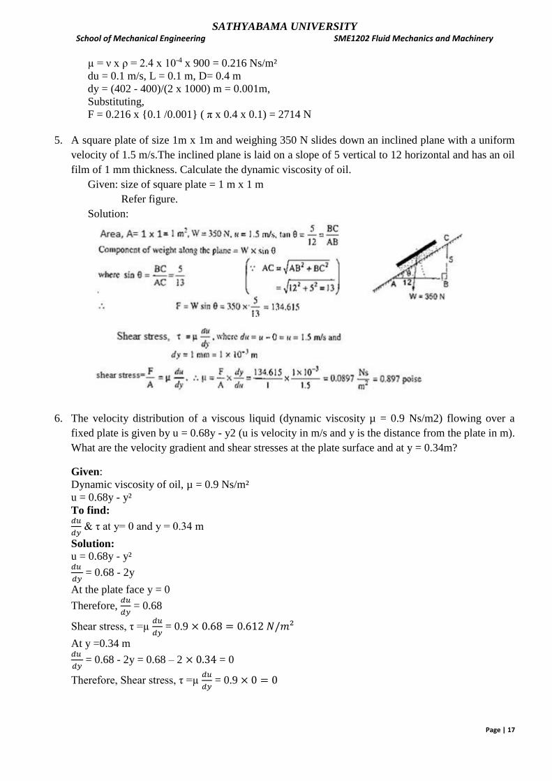
5. A square plate of size 1m x 1m and weighing 350 N slides down an inclined plane with a uniform
velocity of 1.5 m/s.The inclined plane is laid on a slope of 5 vertical to 12 horizontal and has an oil
film of 1 mm thickness. Calculate the dynamic viscosity of oil.
Given: size of square plate = 1 m x 1 m
Refer figure.
Solution:
6. The velocity distribution of a viscous liquid (dynamic viscosity µ = 0.9 Ns/m2) flowing over a
fixed plate is given by u = 0.68y - y2 (u is velocity in m/s and y is the distance from the plate in m).
What are the velocity gradient and shear stresses at the plate surface and at y = 0.34m?
Given:
Dynamic viscosity of oil, µ = 0.9 Ns/m²
u = 0.68y - y²
To find: 𝑑𝑢
𝑑𝑦 & τ at y= 0 and y = 0.34 m
Solution:
u = 0.68y - y² 𝑑𝑢
𝑑𝑦 = 0.68 - 2y
At the plate face y = 0
Therefore, 𝑑𝑢
𝑑𝑦 = 0.68
Shear stress, τ =µ 𝑑𝑢
𝑑𝑦 = 0.9 × 0.68 = 0.612 𝑁/𝑚²
At y =0.34 m 𝑑𝑢
𝑑𝑦 = 0.68 - 2y = 0.68 – 2 × 0.34 = 0
Therefore, Shear stress, τ =µ 𝑑𝑢
𝑑𝑦 = 0.9 × 0 = 0

SATHYABAMA UNIVERSITY School of Mechanical Engineering SME1202 Fluid Mechanics and Machinery
Page | 18
7. Two large surfaces are 2.5 cm apart. This space is filled with an oil of absolute viscosity 0.82
NS/m². Find what force is required to drag a plate of area 0.5m² between the two surfaces at a
speed of 0.6m/s. (i) When the plate is equidistant from the surfaces, (ii) when the plate is at 1cm
from one of the surfaces.
Given: refer figure
Solution:
Case (i) When the plate is equidistant from the surfaces,
Let F1 and F2be the force required to overcome viscous resistance of oil above and below the plate
respectively.
In this case F1 = F2, Since the liquid is same on both side and the plate is equidistant from the
surfaces.
u = du = 0.6 m/s
F1 = F2 = A x µ x du/dy = 0.5 x 0.82 x 0.6/0.0125 = 19.68 N
Total force required, F = F1 + F2 = 19.68+19.68 = 39.36 N
Case (ii) when the plate is at 1cm from one of the surfaces.
Here, F1 ≠ F2
dy1 = 1.5 cm = 0.015 m; dy2= 1cm = 0.01m
F1= A x µ x du/dy1= 0.5 x 0.82 x 0.6/0.015 = 16.4 N
F2 = A x µ x du/dy2= 0.5 x 0.82 x 0.6/0.01= 24.6 N
Total force required, F = F1 + F2 = 16.4+24.6 = 41 N
8. Determine the power dissipated to rotate a shaft of 300 mm diameter at 400 rpm supported at two
journal bearings of 300 mm length with uniform oil thickness of 1 mm. Take viscosity for oil as
0.03 Ns/m².
Given: Dia of Shaft, D= 300 mm= 0.3 m
Speed of rotation, N = 400 rpm
Bearing length, L=300 mm = 0.3 m
No.of bearings = 2
Thickness of oil,dy = 1 mm=0.001 m
Viscosity of oil, µ = 0.03 Ns/m²
Solution:
By Newton’s law of viscosity,
Shear stress, dy
du
For a rotating shaft, u = πDN
60 =
𝜋 x 0.3 x 400
60 = 6.283 m/s

SATHYABAMA UNIVERSITY School of Mechanical Engineering SME1202 Fluid Mechanics and Machinery
Page | 19
°°° shear stress, τ = 0.03 x
6.283
0.001 = 188.49 N/m²
Area of contact between shaft and 2 bearings, A = 2 x πDL = 2 x π x 0.3 x 0.3 = 0.5655 m²
Shear force, F = τ x A = 188.49 x 0.5655 = 106.59 N
Torque, T = F x r = F x D/2 = 106.59 x 0.3/2 = 15.989 Nm
Power dissipated, P = 2πNT
60 =
2π x 400 x 15.989
60 = 669.75 Nm/s or Watts
9. Convert a pressure of 500 kN/m² in terms of i) height of a column of water of density 1000 kg/m³
and ii) height of mercury with specific gravity 13.6 .
We know that,
Pressure p = wh and w = ρ g
h = p/w
Specific weight of water = 1000 x 9.81 = 9810 N/m³ = 9.81 kN/m³
Pressure head of water = hw =500/9.81 = 50.97 m of water
Pressure head, hw = sm x hm
Therefore, hm = hw/sm = 50.97/13.6 = 3.75 m of mercury
10. A Capillary tube having an inside diameter 5mm is dipped in water at 20° C. Determine the rise of
water in the tube. Take σ =0.0736N/m at 20° C.
Dia of glass tube, d = 5 mm = 0.005 m
θ for water = 0°
Capillary rise, h = 𝟒𝝈 𝒄𝒐𝒔ɵ
𝒘 𝒅 = (4 x 0.0736 x cos 0) / (9810 x 0.005) = 0.006 m = 6 mm
11. Calculate capillary rise in a glass tube when immersed in Hg at 20° c. Assume σ for Hg at 20°c as
0.51N/m. The diameter of the tube is 5mm. θ = 130°.
Dia of glass tube, d = 5 mm = 0.005 m
θ for Hg = 130° ; σ = 0.51N/m
Capillary rise, h = 𝟒𝝈 𝒄𝒐𝒔ɵ
𝒘 𝒅 = (4 x 0.51 x cos 130) / [(9810 x 13.6) x 0.005)] = -1.97x10⁻³ m
Negative sign indicates fall of mercury in the tube.
12. Convert the following absolute pressure to gauge pressure:
(a) 120kPa (b) 3kPa (c) 15m of H20 (d) 800mm of Hg.
Solution:
(a) Pabs = Patm + Pgauge
Pgauge = Pabs - Patm = 120- 101.3= 18.7 k Pa
(b) pgauge = 3-101.3 = -98.3 kPa
Pgauge = 98.3 kPa (vacuum)
(C) habs = hatm + hgauge
15 = 10.3+hgauge
hgauge = 4.7m of water
(d) habs = hatm + hgauge
800 =760 + hgauge
hgauge = 40 mm of mercury

SATHYABAMA UNIVERSITY School of Mechanical Engineering SME1202 Fluid Mechanics and Machinery
Page | 20
13. The right limb of a simple U-tube manometer containing mercury is open to the atmosphere while
the left limb is connected to a pipe in which a fluid of specific Gravity, 0.9 is flowing. The centre
of the pipe is 12 cm below the level of mercury in the right limb. Find the pressure of fluid in the
pipe if the difference of mercury level in the two limbs is 22 cm.
Specific gravity of pipe liquid, S1 = 0.9;
Specific gravity of manometer liquid, S2 = 13.6;
Height of pipe liquid above datum, h1 = 22-12 = 10 cm = 0.1 m
Height of manometer liquid above datum, h2 = 22 cm = 0.22 m
Let, Pressure head of fluid in the pipe = hA m of water
Pressure of liquid above datum in the left limb = Pressure of liquid above datum in the right limb
ℎ𝐴 + h1.s1 = h2. s2 m of water
ℎ𝐴 = h2. s2 - h1.s1 = (0.22 x 13.6) – (0.1 x 0.9) = 2 .902 m of water.
Pressure of fluid in the pipe, PA = w.hA = 9.81 x 2.902 = 28.469 kN/m²
where , w = specific weight of water = 9.81 kN/m²
14. A U tube differential mercury manometer is connected to two pipes A and B, both carrying water.
Pipe A lies 1.5 m above Pipe B. The level of mercury raised up in the left limb connected to pipe A
is leveling the centre of pipe B. If the difference in levels of mercury is 7.5 cm and the pressure in
pipe A is 170 kN/m², find the pressure in Pipe B.
Given Data: Refer figure
To find: Pressure in lower pipe-B, pB = ?
Solution:

SATHYABAMA UNIVERSITY School of Mechanical Engineering SME1202 Fluid Mechanics and Machinery
Page | 21
Let Z-Z be the datum (lower level of mercury in right limb connected to pipe-B) Pressure in Pipe- A, pA =170 kN/m² Specific weight of water in pipe A & B,
ѡ𝟏= 9.81 kN/m³
Specific weight of mercury(manometer liquid),
ѡ𝟐 = s2 × ѡ𝒘𝒂𝒕𝒆𝒓 = 13.6 × 9.81 = 133.416
kN/m³
Difference in levels of pipe = h1 = 1.5 m
Difference in levels of mercury,
h2 = h3 =7.5 cm = 0.075 m
Specific gravity of water in pipe –A & pipe-B =
s1=1
Specific gravity of manometer liquid, s2 = 13.6
Manometer equation:
Pressure of liquids above datum in Left limb = Pressure of liquids above datum in right
limb
𝒑𝑨 + ѡ𝟏 𝒉𝟏 + ѡ𝟐 𝒉𝟐 = 𝒑𝑩 + ѡ𝟏 𝒉𝟑
𝒑𝑩 = 𝒑𝑨 + ѡ𝟏 𝒉𝟏 + ѡ𝟐 𝒉𝟐 −ѡ𝟏 𝒉𝟑
= 𝒑𝑨 + ѡ𝟏 𝒉𝟏 + ѡ𝟐 𝒉𝟐 − ѡ𝟏 𝒉𝟐 [ since 𝒉𝟑 = 𝒉𝟐]
= 𝒑𝑨 + ѡ𝟏 𝒉𝟏 + [ѡ𝟐 − ѡ𝟏] × 𝒉𝟐 = 170 + [9.81 × 1.5] + [133.416 - 9.81] × 0.075
= 170 + 14.715 + 9.2705 = 193.9855 kN/m²
15. A rectangular plane surface is 2 m x 3 m is immersed vertically in water. Determine the total
pressure and location of centre of pressure on the plane surface when its upper edge is horizontal
and (a) coincides with water surface, (b) 2.5 m below the free water surface.
Case -1 Case -2
Area, A=2x3= 6 m² Area = 6 m²
x = 3/2 =1.5 m x = 2.5+3/2 =4 m
IG = bd³/12 = 2x3³/12 = 4.5 m4 IG = bd³/12 = 2x3³/12 = 4.5 m4
Total Pressure
P= wA x = 9.81 x 6 x 1.5 = 88.29 kN P = 9.81x 6x4 = 235.44 kN
Depth of centre of centre of pressure
h = x + IG/A x = 1.5+4.5/(6 x1.5) h = 4+4.5/(6x4)
= 2 m = 4.1875 m
𝒑𝑩 = 𝟏𝟗𝟑. 𝟗𝟖𝟓𝟓 𝒌𝑵/𝒎²
SATHYABAMA UNIVERSITY School of Mechanical Engineering SME1202 Fluid Mechanics and Machinery
Page | 22
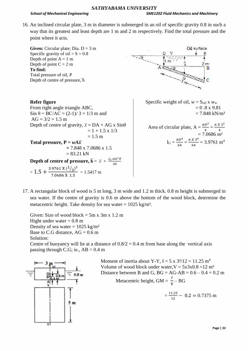
16. An inclined circular plate, 3 m in diameter is submerged in an oil of specific gravity 0.8 in such a
way that its greatest and least depth are 1 m and 2 m respectively. Find the total pressure and the
point where it acts.
Given: Circular plate; Dia. D = 3 m
Specific gravity of oil = S = 0.8
Depth of point A = 1 m
Depth of point C = 2 m
To find:
Total pressure of oil, P
Depth of centre of pressure, h
Refer figure
From right angle triangle ABC,
Sin θ = BC/AC = (2-1)/ 3 = 1/3 m and
AG = 3/2 = 1.5 m
Depth of centre of gravity, x = DA + AG x Sinθ
= 1 + 1.5 x 1/3
= 1.5 m
Total pressure, P = wAx
= 7.848 x 7.0686 x 1.5
= 83.21 kN
Depth of centre of pressure, h = x + 𝐼𝐺 sin²𝜃
𝐴x
= 1.5 +3.9761 X (1 3⁄ )2
7.0686 X 1.5 = 1.5417 m
Specific weight of oil, w = Soil x ww
= 0 .8 x 9.81
= 7.848 kN/m³
Area of circular plate, A = 𝜋𝐷2
4 =
𝜋 𝑋 32
4
= 7.0686 m²
IG = 𝜋𝐷4
64 =
𝜋 𝑋 34
64 = 3.9761 m4
17. A rectangular block of wood is 5 m long, 3 m wide and 1.2 m thick. 0.8 m height is submerged in
sea water. If the centre of gravity is 0.6 m above the bottom of the wood block, determine the
metacentric height. Take density for sea water = 1025 kg/m³.
Given: Size of wood block = 5m x 3m x 1.2 m
Hight under water = 0.8 m
Density of sea water = 1025 kg/m³
Base to C.G distance, AG = 0.6 m
Solution:
Centre of buoyancy will lie at a distance of 0.8/2 = 0.4 m from base along the vertical axis
passing through C.G; ie., AB = 0.4 m
Moment of inertia about Y-Y, I = 5 x 3³/12 = 11.25 m4
Volume of wood block under water,V = 5x3x0.8 =12 m³
Distance between B and G, BG = AG-AB = 0.6 – 0.4 = 0.2 m
Metacentric height, GM = 𝐼
V – BG
= 11.25
12− 0.2 = 0.7375 m

SATHYABAMA UNIVERSITY School of Mechanical Engineering SME1202 Fluid Mechanics and Machinery
Page | 23
18. An object weighing 2200 N in water has dimensions 1.75 rn x 1.25 m x 2.25 m, Find its weight
in air and its specific gravity.
Given :
Size of the object = 1.75 m x 1.25 m x 2.25 m
Weight when in water = 2200 N
Solution:
Volume of the object = 1.75 m x 1.25 m x 2.25 m = 4.921875 m³
Volume of the water displaced - Volume of the object = 4.921875 m³
.-. Weight of water displaced = 9810 x 4.921875 = 48283.59375 N
For the equilibrium of the object
Weight of object in air - Weight of water displaced = Weight in water
Weight of object in air – 48283.59375 = 2200
Weight of object in air = 48283.59375 + 2200 = 50483.59375N
Weight in air = 50483.59375 N
Specific weight ot the object = W/V = 50483.59375 /4.921875 = 10256.9841 N/m³
Specific gravity = specic weight of object
specific weight of water =
10256.9841
9810 = 1.046
19. A cylindrical solid of 4 m diameter and height 4 m is floating in water with its axis vertical.
Find the meta-centric height of the cylinder if she specific gravity of the material of cylinder =0.6
and State whether the equilibrium is stable or unstable.

SATHYABAMA UNIVERSITY School of Mechanical Engineering SME1202 Fluid Mechanics and Machinery
Page | 24
As the metacentric height is negative, metacentre point M lies below centre of gravity point G and
hence the cylinder will be in unstable equilibrium and hence cylinder will not float vertically.
Questions for practice:
PART - A
1. Define fluid and fluid mechanics.
2. Define real and ideal fluids.
3. Define mass density and specific weight.
4. Distinguish between fluid statics and kinematics.
5. Define viscosity.
6. Define specific volume.
7. Define specific gravity.
8. Distinct b/w capillarity and surface tension.
9. Calculate the specific weight, density and specific gravity of 1 liter liquid which weighs
7N.
10. State Newton’s law of viscosity.
11. Name the types of fluids.
12. Define compressibility.
13. Define kinematic viscosity.
14. Find the kinematic viscosity of oil having density 981 kg/m3. The shear stress at a point in
oil is 0.2452N/m2 and velocity gradient at that point is 0.2/sec.
15. Determine the specific gravity of a fluid having 0.05 poise and kinematic viscosity 0.035
stokes.
16. Find out the minimum size of glass tube that can be used to measure water level if the
capillary rise is restricted to 2 mm. Consider surface tension of water in contact with air
as 0.073575 N/m.
17. Write down the expression for capillary fall.
18. Explain vapour pressure .
19. Two horizontal plates are placed 1.25 cm apart. The space between them is being filled
with oil of viscosity 14 poises. Calculate the shear stress in oil if upper plate is moved
with a velocity of 2.5 m/s.
20. State Pascal’s law.
21. What is mean by absolute and gauge pressure and vacuum pressure?
22. Define Manometer and list out its types.
23. Define centre of pressure and total pressure.
24. Define buoyancy and centre of buoyancy.

SATHYABAMA UNIVERSITY School of Mechanical Engineering SME1202 Fluid Mechanics and Machinery
Page | 25
25. Define Meta centre.
26. Define Hydro static Pressure. 27. What is stable equilibrium of floating bodies? 28. What is stable equilibrium of submerged bodies?
PART – B
1. Calculate the capillary effect in a glass tube of 4.5 mm diameter, when immersed in (a) water
(b) mercury. The temperature of the liquid is 20o C and the values of the surface tension of
water and mercury at 20o C in contact with air are 0.073575 N/m and 0.51 N/m respectively.
The angle of contact for water is zero that for mercury 130o. Take specific weight of water as
9800 N/m3.
2. If the velocity profile of a liquid over a plate is a parabolic with the vertex 202 cm from the plate, where the velocity is 120 cm/sec. calculate the velocity gradients and shear stress at a distance of 0, 10 and 20 cm from the plate, if the viscosity of the fluid is 8.5 poise.
3. The dynamic viscosity of oil, used for lubrication between a shaft and sleeve is 6 poise. The shaft is of diameter 0.4 m and rotates at 190 rpm. Calculate the power lost in the bearing for a sleeve length of 90mm. the thickness of the oil film is 1.5 mm.
4. If the velocity distribution over a plate is given by u=2/3 y – y2 in which u is the velocity in
m/s at a distance y meter above the plate, determine the shear stress at y = 0 and y = 0.15 m.
5. The velocity distribution of flow is given by u = ly² + my+c with vertex 30 cm from the plate,
where velocity is 1.8 m/s. If µ = 0.9 Ns/m², find the velocity gradients and shear stresses at y =
0, 15 and 30 cm from the plate.
6. Derive Pascal’s law.
7. Derive expression for capillary rise and fall. 8. Two large plane surfaces are 2.4 cm apart. The space between the gap is filled with glycerin.
What force is required to drag a thin plate of size 0.5 m between two large plane surfaces at a
speed of 0.6 m/sec. if the thin plate is (i) in the middle gap (ii) thin plate is 0.8 cm from one
of the plane surfaces? Take dynamic viscosity of fluid is 8.1 poise.
9. Calculate the capillary rise in a glass tube of 2.5 mm diameter when immersed vertically in (a) water
(b) mercury. Take surface tension = 0.0725 N/m for water and = 0.52 N/m for mercury in contact
with air. The specific gravity for mercury is given as 13.6 and angle of contact of mercury with glass =
130o.
10. A U - Tube manometer is used to measure the pressure of water in a pipe line, which is in
excess of atmospheric pressure. The right limb of the manometer contains water and mercury
is in the left limb. Determine the pressure of water in the main line, if the difference in level
of mercury in the limbs of U tube is 10 cm and the free surface of mercury is in level with over
the centre of the pipe. If the pressure of water in pipe line is reduced to 9810 N/m2,
Calculate the new difference in the level of mercury. Sketch the arrangement in both cases.

SATHYABAMA UNIVERSITY School of Mechanical Engineering SME1202 Fluid Mechanics and Machinery
Page | 26
11. Calculate the total hydrostatic force and location of centre of pressure for a circular
plate of 2.5 m diameter when immersed vertically in an oil of specific gravity 0.8 with its top edge
1.5 m below the oil.
12. A rectangular plate 2.5m x 3.5 m is submerged in water and makes an angle of 60°
with the horizontal, the 2.5m sides being horizontal. Calculate the total force
on the plate and the location of the point of application of the force, when the top edge of
the plate is 1.6m below the water surface.
13. A rectangular plate 1.5 m x 3 m is immersed in an oil of specific gravity 0.82 such that its
upper and lower edge is at depths 1.5 m and 3 m respectively. Determine the total pressure
acting on the plate and its location.
14. In an open container water is filled to a height of 2.5m and above that an oil of Specific
gravity 0.85 is filled for a depth of 1.4 m. Find the intensity of pressure at the interface of
two liquids and at the bottom of the tank.
15. The pressure Intensity at a point is 40kPa. Find corresponding pressure head in (a) water (b)
Mercury (c) oil of specific gravity 0.9.
16. a)Calculate intensity of pressure due to a column of 0.3m of (a) water (b) Mercury (c) Oil of
specific gravity 0.8. Also express the same in absolute units.
b)Convert the following absolute pressure in to gauge pressure: (a) 110kPa (b) 7.3 kPa (c) 17
m of water (d) 860 mm of Mercury.
17. a)Convert a pressure head of 10 m of water column to kerosene of specific gravity 0.8 and carbon-
tetra-chloride of specific gravity of 1.62.
b)Determine (a) the gauge pressure and (b) The absolute pressure of water at a depth of 9 m from
the surface.

SATHYABAMA UNIVERSITY School of Mechanical Engineering SME1202 Fluid Mechanics and Machinery
Page | 27
UNIT 2 EQUATIONS OF MOTION
Basic equations of motion: Types of fluid flow, concept of Control Volume – Control volume
analysis of mass, momentum and energy. Differential equations of continuity and momentum.
Euler’s equation and Bernoulli’s equation & its applications. Flow measurement – Orifice meter,
Venturimeter and Pitot tube.
Fluid flow is described by two methods: Lagrangian method & Eulerian method
In the Lagrangian method a single particle is followed over the flow field with the co ordinate system
following the particle. The flow description is particle based and not space based. A moving
coordinate system has to be used.
In the Eulerian method, the description of flow is based on fixed coordinate system and the
description of the velocity is with reference to location and time.
Hence, Eulerian approach is easily adoptable to describe fluid motion mathematically.
Control volume
A fixed volume in space whose size and shape is entirely arbitrary, through which a fluid is
continuously flowing is known as control volume. The boundary of a control volume is termed as the
control surface. The size and shape is arbitrary and normally chosen such that it encloses part of the
flow of particular interest.
Types of Fluid Flow:
1)Steady flow: The flow in which the fluid characteristics like velocity, pressure, density etc. at a
point do not change with time is defined as steady flow.
Mathematically, for steady flow,
0
t
v, 0
t
p, 0
t
Unsteady Flow: The flow, in which the velocity, pressure and density at a point changes with respect
to time is defined as unsteady flow.
Mathematically, for unsteady flow
,0
t
v0
t
p, 0
t
2. Uniform flows: The flow in which the velocity at any given time does not change with respect to
distance is defined as Uniform flow.
Mathematically, for uniform flow
,0tan
tconsts
v
v Change of velocity s distance of flow.
Non-uniform flow: The flow in which the velocity at any given time changes with respect to
distance is defined as non uniform flow.
Mathematically, for non-uniform flow,
0tan
tconsts
v
3. Laminar flow: The flow in which the fluid particles move along well-defined paths which are
straight and parallel is defined as laminar flow. Thus the particles move in layers and do not cross
each other.
Turbulent flow: The flow in which the fluid particles do not move in a zig-zag way and the adjacent
layers cross each other is defined as turbulent flow.

SATHYABAMA UNIVERSITY School of Mechanical Engineering SME1202 Fluid Mechanics and Machinery
Page | 28
Laminar flow Turbulent flow
4. Compressible flow: The flow in which the density of fluid changes from point to point ie., ρ is not
constant for the fluid, is defined as compressible flow.
Mathematically, for compressible flow, ρ ≠ constant.
Incompressible flow: The flow in which the density of fluid is constant is defined as incompressible
flow.
Liquids are generally incompressible while gases are compressible.
Mathematically, for incompressible flow, Constant
5.Rotational flow: The flow in which the fluid particles while flowing along stream-lines, also rotate
about their own axes, that type of flow is known as rotational flow.
Irrotational flow: The flow in which the fluid particles while flowing along stream-lines, do not
rotate about their own axes, that type of flow is called irrotational flow.
6. One Dimensional Flow:
One dimensional flow is that type of flow in which the fluid velocity is a function of one-
space-co-ordinate only. The variation of velocities in other two mutually perpendicular directions is
assumed negligible.
Mathematically, for one-dimensional flow
xfu , v = 0 and w = 0
where u, v and w are velocity components in x, y and z directions respectively.
Two-dimensional flow:
It is that type of flow in which the velocity is a function of two space co-ordinates only. Thus,
mathematically for two dimensional flow
,y,xfu 1 y,xfv 2 and w = 0
Three-dimensional flow:
It is the type of flow in which the velocity is a function of three space co-ordinates (x, y and z).
Mathematically for three dimensional flow,
,z,y,xfu 1 z,y,xfv 2 , z,y,xfw 3 .
Path line:
A path line is the trajectory of an individual element of fluid.
Streamline
A streamline is a an imaginary continuous line within a moving fluid such that the tangent at each
point is the direction of the flow velocity vector at that point.
Stream tube An imaginary tube (need not be circular) formed by collection of neighboring streamlines through
which the fluid flows is known as stream tube.

SATHYABAMA UNIVERSITY School of Mechanical Engineering SME1202 Fluid Mechanics and Machinery
Page | 29
Conservation of Mass, momentum and Energy
Conservation of mass or Continuity Equation: Integral Form
Let us consider a control volume V bounded by the control surface S. The efflux of mass across the
control surface S is given by
where is the velocity vector at an elemental area(which is treated as a vector by considering its
positive direction along the normal drawn outward from the surface).
A Control Volume for integral form of derivation
The rate of mass accumulation within the control volume becomes
where dV is an elemental volume, ρ is the density and V is the total volume bounded by the control
surface S. Hence, the continuity equation becomes
---------------------------(1)
The second term of the Equation can be converted into a volume integral by the use of the Gauss
divergence theorem as

SATHYABAMA UNIVERSITY School of Mechanical Engineering SME1202 Fluid Mechanics and Machinery
Page | 30
Since the volume V does not change with time, the sequence of differentiation and integration in the
first term of Equation (1) can be interchanged and it can be written as
Equation (2) is valid for any arbitrary control volume irrespective of its shape and size. So we can
write
Conservation of Energy (Integral Form)
The law of conservation of energy says “energy cannot be created or be destroyed; One form of
energy can be changed into another form only”.
Consider the Control Volume shown in Figure as a thermodynamic system. Let amount of heat δq be
added to the system from the surrounding. Also let δw be the work done on the system by the
surroundings. Both heat and work are the forms of energy. Addition of any form of the energy to the
system, changes the amount of internal energy of the system. Lets denote this change of internal
energy by de. As per the principle of energy conservation,
δq + δw = de
Therefore in terms of rate of change, the above equation changes to
For an open system there will be a change in all the forms of energies possessed by the system, like
internal energy and kinetic energy. The right hand side of the equation (1) is representing change in
the content of energy of the system.
If q is the amount of heat added per unit mass, then the rate of heat addition for any elemental
volume will be q(ρdv) . The total external volumetric heat addition on the entire control volume and
heat got added by viscous effects like conduction can be,
The main source of work transfer is due to the surface forces like pressure, body force etc. Consider
an elemental area ds of the control surface. The pressure force on this elemental area is -Pds and the
rate of work done on the fluid passing through ds with velocity V is (-Pds).V. Integrating over the
complete control surface, rate of work done due to pressure force is,

SATHYABAMA UNIVERSITY School of Mechanical Engineering SME1202 Fluid Mechanics and Machinery
Page | 31
In addition, consider an elemental volume dυ inside the control volume, as shown in Figure.
The rate of work done on the elemental
volume due to body force is (ρFbdu).V. Here
Fb is the body force per unit mass. Summing
over the complete control volume, we obtain,
rate of work done on fluid inside υ due to
body forces is
If the flow is viscous, the shear stress on the control surface will also do work on the fluid as it
passes across the surface. Let Wviscous denote the work done due to the shear stress. Therefore, the
total work done on the fluid inside the control volume is the sum of terms given by (3) and (4)
and Wviscous, that is
For the open system considered, the changes in internal energy as well as kinetic energy need to be
accounted. Therefore, right hand side of equation (1) should deal with total energy (sum of internal
and kinetic energies) of the system. Let, e be the internal energy per unit mass of the system and
kinetic energy per unit mass due to local velocity V be V²/2. Hence the rate of change of total energy
is
𝛿
𝛿𝑡∰ 𝜌[𝑒 +
𝑉2
2] 𝑑𝑣
𝑣 ------------------------ (6)
Total energy in the control volume might also change due to influx and outflux of the fluid. The
elemental mass flow across ds is (ρV.ds). Therefore the elemental flow of total energy across the ds
is (ρV.ds)(e+V²/2).
For the complete control surface, net rate of flow of total energy will be,
∯(𝜌𝑉 𝑑𝑠) [𝑒 +𝑉2
2]
𝑠dv -------------------------(7)
Hence the net energy change of the control volume is,
------- (8)
Thus, substituting Equations (2), (5) and (8) in equation (1), we have

SATHYABAMA UNIVERSITY School of Mechanical Engineering SME1202 Fluid Mechanics and Machinery
Page | 32
-----(9)
This is the energy equation in the integral form. It is essentially the first law thermodynamics applied
to fluid flow or open system.
One dimensional form of Conservation of Energy
Consider the control volume shown in Figure for steady inviscid flow without body force, Then the
equation (9) reduces to,
Let us denote the first term on left hand side of above equation by to represent the total external
heat addition in the system. Thus, above equation becomes
𝑄 − ∯ 𝑃𝑉𝑑𝑠 = ∯ 𝜌 [𝑒 +𝑉2
2]
𝑠
𝑠𝑉 𝑑𝑠
Evaluating the surface integrals over the control volume in Figure, we obtain
or
or
or
Here, /ρ1u1A is the external heat added per unit mass, q. Also, we know e + Pu = h. Hence, above
equation can be re-written as,
----------------------------------------- (10)
This is the energy equation for steady one-dimensional flow for inviscid flow.
Conservation of Momentum (Integral Form) Momentum is defined as the product of mass and velocity, and represents the energy of motion
stored in the system. It is a vector quantity and can only be defined by specifying its direction as well
as magnitude.
The conservation of momentum is defined by Newton’s second law of motion.
Newton's Second Law of Motion
"The rate of change of momentum is proportional to the net force acting, and takes place in the
direction of that force".
This can be expressed as
--------------------------------------------------- (1)

SATHYABAMA UNIVERSITY School of Mechanical Engineering SME1202 Fluid Mechanics and Machinery
Page | 33
Consider the same Control Volume shown in Figure for deriving the momentum conservation
equation. Right hand side of equation (1) is the summation of all forces like surface forces and body
forces. Let Fb and P be the net body force per unit mass and pressure exerted on control
surface respectively. The body force on the elemental volume dυ is therefore ρ Fb dv and the total
body force exerted on the fluid in the control volume is
---- --------------------------------------------------- (2)
The surface force due to pressure acting on the element of area ds is –Pds, where the negative sign
indicates that the force is in the opposite direction of ds.
The total pressure force over the entire control surface is expressed as
--------------------------------------------------------- (3)
Let Fviscousbe the total viscous force exerted on the control surface. Hence, the resultant force
experienced by the fluid is given by
--------------------------------------------------- (4)
The left hand side term of the Equation (1) gives the time rate of change of momentum following a
fixed fluid element or substantial derivative of the momentum. It can be evaluated using equation (2)
by evaluating the sum of net flow of momentum leaving the control volume through the control
surface S and time rate of change of momentum due to fluctuations of flow properties inside the
control volume.
The mass flow across the elemental area ds is (ρV.ds).Therefore, the flow of momentum per second
across ds is (ρV.ds)V
The net flow of momentum out of the control volume through s is ,
------------------------------------------------------ (5)
The momentum of the fluid in the elemental volume dυ is (ρ du)V. The momentum contained at any
instant inside the control volume is
and its time rate of change due to unsteady flow fluctuation is
------------------------------------------------------------------ (6)
Combining Equations (5) and (6) to obtain the left hand side of equation (1), we get
------------------------ (7)
Thus, substituting Equations (4) and (7) into (1), we have
-------------------- (8)
This is the momentum equation in integral form.
It is a general equation, applies to the unsteady, three-dimensional flow of any fluid, compressible or
incompressible, viscous or non viscous.

SATHYABAMA UNIVERSITY School of Mechanical Engineering SME1202 Fluid Mechanics and Machinery
Page | 34
One dimensional form of Momentum conservation Equation For the steady and non viscous flow with no body forces, the Equation (8) reduces to
Above equation is a vector equation. However, since we are dealing with the one-dimensional flow,
we need to consider only the scalar x component of equation.
Considering the control volume shown in Figure, above equation transforms to,
ρ1(-u1A)u1 + ρ2(-u2A)u2 = -(-P1A + P2A)
or
--------------------------------------------------------- (9)
This is the momentum equation for steady,non viscous one-dimensional flow.
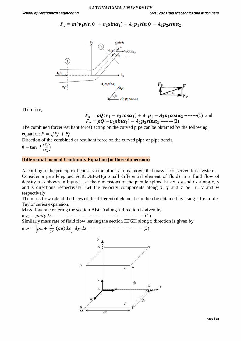
One Dimensional flow – Forces of fluid in a Curved Pipe
In the case where fluid flows in a curved pipe as shown in figure, let ABCD be the control volume,
A1, A2 the areas, v1, v2 the velocities, and p1,p2 the pressures of sections AB and CD respectively. Let
F be the force of fluid acting on the pipe; the force of the pipe acting on the fluid is -F. This force and
the pressures acting on sections AB and CD act on the fluid, increasing the fluid momentum by such
a combined force (Increase in momentum = momentum going out - momentum coming in).
If Fx and Fy are the component forces in the x and y directions of F respectively, then from the
equation of momentum,
Fx + A1p1 cos α1- A2p2 cos α2 = m (v2 cos α2 - v1 cos α1)
Fy + A2p2 sinα2 - A2p2 sinα2 = m(v2 sinα2 –v1 sinα1)
From the above equations , Fx and Fy are given by
𝑭𝒙 = 𝒎(𝒗𝟏𝒄𝒐𝒔𝜶𝟏 − 𝒗𝟐𝒄𝒐𝒔𝜶𝟐) + 𝑨𝟏𝒑𝟏𝒄𝒐𝒔𝜶𝟏 − 𝑨𝟐𝒑𝟐𝒄𝒐𝒔𝜶𝟐
𝑭𝒚 = 𝒎(𝒗𝟏𝒔𝒊𝒏𝜶𝟏 − 𝒗𝟐𝒔𝒊𝒏𝜶𝟐) + 𝑨𝟏𝒑𝟏𝒔𝒊𝒏𝜶𝟏 − 𝑨𝟐𝒑𝟐𝒔𝒊𝒏𝜶𝟐
In these equations, m is the mass flow rate. If Q is the volumetric flow rate, then the following
relation exists:
m = ρA1v1 = ρA2v2 = ρQ
If the curved pipe is a pipe bend in a horizontal plane, then α1= 0. Therefore 𝑭𝒙 = 𝒎(𝒗𝟏𝒄𝒐𝒔 𝟎 − 𝒗𝟐𝒄𝒐𝒔𝜶𝟐) + 𝑨𝟏𝒑𝟏𝒄𝒐𝒔 𝟎 − 𝑨𝟐𝒑𝟐𝒄𝒐𝒔𝜶𝟐
SATHYABAMA UNIVERSITY School of Mechanical Engineering SME1202 Fluid Mechanics and Machinery
Page | 35
𝑭𝒚 = 𝒎(𝒗𝟏𝒔𝒊𝒏 𝟎 − 𝒗𝟐𝒔𝒊𝒏𝜶𝟐) + 𝑨𝟏𝒑𝟏𝒔𝒊𝒏 𝟎 − 𝑨𝟐𝒑𝟐𝒔𝒊𝒏𝜶𝟐
Therefore, 𝑭𝒙 = 𝝆𝑸(𝒗𝟏 − 𝒗𝟐𝒄𝒐𝒔𝜶𝟐) + 𝑨𝟏𝒑𝟏 − 𝑨𝟐𝒑𝟐𝒄𝒐𝒔𝜶𝟐 --------(1) and
𝑭𝒚 = 𝝆𝑸(−𝒗𝟐𝒔𝒊𝒏𝜶𝟐) − 𝑨𝟐𝒑𝟐𝒔𝒊𝒏𝜶𝟐 --------(2)
The combined force(resultant force) acting on the curved pipe can be obtained by the following
equation: 𝐹 = √𝐹𝑥2 + 𝐹𝑦2
Direction of the combined or resultant force on the curved pipe or pipe bends,
θ = tan−1 (𝐹𝑦
𝐹𝑥)
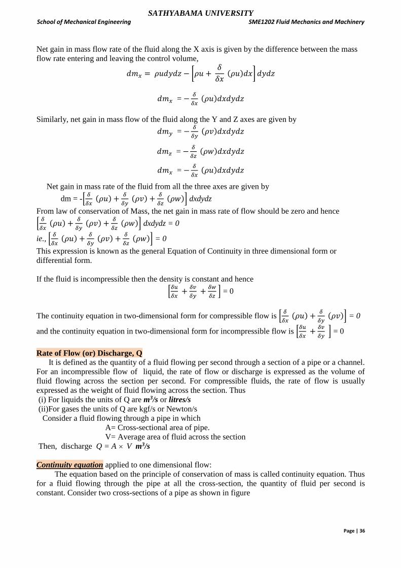
Differential form of Continuity Equation (in three dimension)
According to the principle of conservation of mass, it is known that mass is conserved for a system.
Consider a parallelepiped AHCDEFGH(a small differential element of fluid) in a fluid flow of
density ρ as shown in Figure. Let the dimensions of the parallelepiped be dx, dy and dz along x, y
and z directions respectively. Let the velocity components along x, y and z be u, v and w
respectively.
The mass flow rate at the faces of the differential element can then be obtained by using a first order
Taylor series expansion.
Mass flow rate entering the section ABCD along x direction is given by
mx1 = 𝜌𝑢𝑑𝑦𝑑𝑧 ---------------------------------------------------------(1)
Similarly mass rate of fluid flow leaving the section EFGH along x direction is given by
mx2 = ⌊𝜌𝑢 + 𝛿
𝛿𝑥 (𝜌𝑢)𝑑𝑥⌋ 𝑑𝑦 𝑑𝑧 ---------------------------------(2)
SATHYABAMA UNIVERSITY School of Mechanical Engineering SME1202 Fluid Mechanics and Machinery
Page | 36
Net gain in mass flow rate of the fluid along the X axis is given by the difference between the mass
flow rate entering and leaving the control volume,
𝑑𝑚𝑥 = 𝜌𝑢𝑑𝑦𝑑𝑧 − [𝜌𝑢 + 𝛿
𝛿𝑥 (𝜌𝑢)𝑑𝑥] 𝑑𝑦𝑑𝑧
𝑑𝑚𝑥 = −𝛿
𝛿𝑥 (𝜌𝑢)𝑑𝑥𝑑𝑦𝑑𝑧
Similarly, net gain in mass flow of the fluid along the Y and Z axes are given by
𝑑𝑚𝑦 = −𝛿
𝛿𝑦 (𝜌𝑣)𝑑𝑥𝑑𝑦𝑑𝑧
𝑑𝑚𝑧 = −𝛿
𝛿𝑧 (𝜌𝑤)𝑑𝑥𝑑𝑦𝑑𝑧
𝑑𝑚𝑥 = −𝛿
𝛿𝑥 (𝜌𝑢)𝑑𝑥𝑑𝑦𝑑𝑧
Net gain in mass rate of the fluid from all the three axes are given by
dm = -[𝛿
𝛿𝑥 (𝜌𝑢) +
𝛿
𝛿𝑦 (𝜌𝑣) +
𝛿
𝛿𝑧 (𝜌𝑤)] dxdydz
From law of conservation of Mass, the net gain in mass rate of flow should be zero and hence
[𝛿
𝛿𝑥 (𝜌𝑢) +
𝛿
𝛿𝑦 (𝜌𝑣) +
𝛿
𝛿𝑧 (𝜌𝑤)] dxdydz = 0
ie., [𝛿
𝛿𝑥 (𝜌𝑢) +
𝛿
𝛿𝑦 (𝜌𝑣) +
𝛿
𝛿𝑧 (𝜌𝑤)] = 0
This expression is known as the general Equation of Continuity in three dimensional form or
differential form.
If the fluid is incompressible then the density is constant and hence
[𝛿𝑢
𝛿𝑥 +
𝛿𝑣
𝛿𝑦 +
𝛿𝑤
𝛿𝑧 ] = 0
The continuity equation in two-dimensional form for compressible flow is [𝛿
𝛿𝑥 (𝜌𝑢) +
𝛿
𝛿𝑦 (𝜌𝑣)] = 0
and the continuity equation in two-dimensional form for incompressible flow is [𝛿𝑢
𝛿𝑥 +
𝛿𝑣
𝛿𝑦 ] = 0
Rate of Flow (or) Discharge, Q It is defined as the quantity of a fluid flowing per second through a section of a pipe or a channel.
For an incompressible flow of liquid, the rate of flow or discharge is expressed as the volume of
fluid flowing across the section per second. For compressible fluids, the rate of flow is usually
expressed as the weight of fluid flowing across the section. Thus
(i) For liquids the units of Q are m3/s or litres/s
(ii)For gases the units of Q are kgf/s or Newton/s
Consider a fluid flowing through a pipe in which
A= Cross-sectional area of pipe.
V= Average area of fluid across the section
Then, discharge Q = A V m3/s
Continuity equation applied to one dimensional flow:
The equation based on the principle of conservation of mass is called continuity equation. Thus
for a fluid flowing through the pipe at all the cross-section, the quantity of fluid per second is
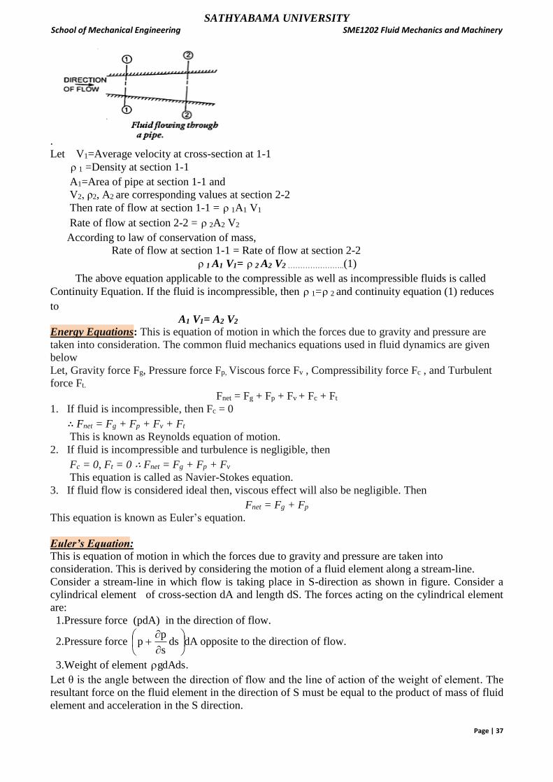
constant. Consider two cross-sections of a pipe as shown in figure
SATHYABAMA UNIVERSITY School of Mechanical Engineering SME1202 Fluid Mechanics and Machinery
Page | 37
.
Let V1=Average velocity at cross-section at 1-1
1 =Density at section 1-1
A1=Area of pipe at section 1-1 and
V2, ρ2, A2 are corresponding values at section 2-2
Then rate of flow at section 1-1 = 1A1 V1
Rate of flow at section 2-2 = 2A2 V2
According to law of conservation of mass,
Rate of flow at section 1-1 = Rate of flow at section 2-2
1 A1 V1= 2 A2 V2 …………………..(1)
The above equation applicable to the compressible as well as incompressible fluids is called
Continuity Equation. If the fluid is incompressible, then 1= 2 and continuity equation (1) reduces
to
A1 V1= A2 V2
Energy Equations: This is equation of motion in which the forces due to gravity and pressure are
taken into consideration. The common fluid mechanics equations used in fluid dynamics are given
below
Let, Gravity force Fg, Pressure force Fp, Viscous force Fv , Compressibility force Fc , and Turbulent
force Ft.
Fnet = Fg + Fp + Fv + Fc + Ft
1. If fluid is incompressible, then Fc = 0
∴ Fnet = Fg + Fp + Fv + Ft
This is known as Reynolds equation of motion.
2. If fluid is incompressible and turbulence is negligible, then
Fc = 0, Ft = 0 ∴ Fnet = Fg + Fp + Fv
This equation is called as Navier-Stokes equation.
3. If fluid flow is considered ideal then, viscous effect will also be negligible. Then
Fnet = Fg + Fp
This equation is known as Euler’s equation.
Euler’s Equation: This is equation of motion in which the forces due to gravity and pressure are taken into
consideration. This is derived by considering the motion of a fluid element along a stream-line.
Consider a stream-line in which flow is taking place in S-direction as shown in figure. Consider a
cylindrical element of cross-section dA and length dS. The forces acting on the cylindrical element
are:
1.Pressure force (pdA) in the direction of flow.
2.Pressure force dAdss
pp
opposite to the direction of flow.
3.Weight of element .gdAds
Let θ is the angle between the direction of flow and the line of action of the weight of element. The
resultant force on the fluid element in the direction of S must be equal to the product of mass of fluid
element and acceleration in the S direction.

SATHYABAMA UNIVERSITY School of Mechanical Engineering SME1202 Fluid Mechanics and Machinery
Page | 38
.
saxdAdScosgdAdSdAdss
pppdA
-----(1)
where as is the acceleration in the direction of S.
Now as=dt
dv, where v is a function of s and t.
t
v
s
vv
t
v
dt
ds
s
v
v
dt
ds
If the flow is steady, 0t
v
s
vva s
Substituting the value of as in equation (1) and simplifying the equation, we get
s
vvxdAdscosgdAdsdsdA
s
p
Dividing by ,dsdA s
vvcosg
s
p
0s
vvcosg
s
p
But from the figure ds
dzcos
0vdvgdzp
or0s
vv
ds
dzg
s
p1
0vdvgdzp
-----------------(2)
The above equation is known as Euler’s equation of motion.
Bernoulli’s equation is obtained by integrating the above Euler’s equation of motion.
∫𝜕𝑝
𝜌 +∫𝑔𝑑𝑧 + ∫𝑣𝑑𝑣 = 𝑐𝑜𝑛𝑠𝑡𝑎𝑛𝑡
If the flow is incompressible, ρ is a constant and
constant2
2
v
gzp
SATHYABAMA UNIVERSITY School of Mechanical Engineering SME1202 Fluid Mechanics and Machinery
Page | 39
constant2
2
g
vz
g
p
constant2
2
zg
v
w
p ------------(3)
The above equation is known as Bernoulli’s equation.
w
p
pressure energy per unit weight of fluid or pressure Head
g2
v 2
kinetic energy per unit weight of fluid or kinetic Head
Z = potential energy per unit weight of fluid or potential Head or Datum head
Assumptions made in deriving Bernoulli’s equation:
The following are the assumptions made in the derivation of Bernoulli’s equation: (i) The fluid is ideal,
(ii) The flow is steady
(iii) The flow is frictionless
(iv) The flow is incompressible
(v) The flow is irrotational
Statement of Bernoulli’s Theorem: “ In a steady, frictionless, incompressible and irrotational flow of an ideal fluid, the total energy at
any point of the fluid is constant”.
The total energy consists of pressure energy, kinetic energy and potential energy or datum energy.
Thus mathematically, Bernoulli’s theorem is written as
constant2
2
zg
v
w
p
Applications of Bernoulli’s equation:
1.Venturimeter 2. Orifice meter and 3. Pitot tube.
Flow measurement devices:
Venturimeter and Orifice meter are the devices used for measurement of flow rate or actual
discharge through pipes.
Pitot tube is used to measure the velocity of flow in open canals, pipes as well as measurement of
speed of ships, Aircrafts.
Venturimeter:
A venturimeter is a device used for measuring the rate of a flow of a fluid flowing through a pipe. It
is based on the principle of Bernoulli’s equation. The Venturimeter has a converging conical section
from the initial pipe diameter, followed by a throat, ended with a diverging conical section back to
the original pipe diameter.
As the inlet area of the venturimeter is larger than the throat area, the velocity at the throat increases
resulting in decrease of pressure. By this, a pressure difference is created between the inlet and the
throat of the venturimeter. The pressure difference is measured by using a differential U-tube
manometer. This pressure difference helps in the determination of rate of flow of fluid or discharge
through the pipe line.
Let, D1 and D2 — Diameter at inlet and throat
p1and p2 — Pressure at inlet and throat
V1 and V2 — Velocity at inlet and throat

SATHYABAMA UNIVERSITY School of Mechanical Engineering SME1202 Fluid Mechanics and Machinery
Page | 40
Z1 and Z2 --- Datum head at inlet and throat respectively.
x – deflection of manometer liquid
Applying Bernoulli's equation at section (1) and (2), we get,
𝑝1
𝑤 +
𝑣12
2𝑔 + 𝑍1 =
𝑝2
𝑤 +
𝑣22
2𝑔 + 𝑍2
As pipe is horizontal, hence 𝑧1 = 𝑧2
Therefore, 𝑝1
𝑤 +
𝑣12
2𝑔 =
𝑝2
𝑤 +
𝑣22
2𝑔
𝑝1
𝑤 -
𝑝2
𝑤 =
𝑣22
2𝑔 -
𝑣12
2𝑔 -------------------------------------- (1)
But, 𝑝1
𝑤 -
𝑝2
𝑤 = pressure head difference between inlet 1 and throat 2 = h
𝑝1
𝑤 -
𝑝2
𝑤 = h
Therefore, equation (1) becomes, h = 𝑣22
2𝑔 -
𝑣12
2𝑔 ------------------ (2)
By continuity equation, A1V1 = A 2 V2
V1 = 𝐴2𝑉2
𝐴1, and substituting this in equation (2), h =
𝑣22
2𝑔 –
(𝐴2𝑉2𝐴1 )
2
2𝑔
Or h = 𝑣22
2𝑔 (1 −
𝐴22
𝐴12) =
𝑣22
2𝑔 (𝐴12−𝐴2
2
𝐴12 )
𝑣22 = 2gh(
𝐴12
𝐴12−𝐴2
2) or 𝑣2 = √2𝑔ℎ x
𝐴1
√𝐴12−𝐴2
2
Theoretical Discharge, Qth = A 2 V2 = A 2 x √2𝑔ℎ x 𝐴1
√𝐴12−𝐴2
2
Qth = 𝐴1𝐴2
√𝐴12−𝐴2
2√2𝑔ℎ
SATHYABAMA UNIVERSITY School of Mechanical Engineering SME1202 Fluid Mechanics and Machinery
Page | 41
Actual discharge through the venturimeter, 𝑄𝑎 = 𝐶𝑑𝐴1𝐴2
√𝐴12−𝐴2
2√2𝑔ℎ , 𝑚
3
𝑠⁄
The liquid in the manometer is heavier than the liquid flowing through the pipe
S2 : Specific gravity of the manometer liquid.
S1 :Specific gravity of the flowing liquid. (S2 > S1)
Therefore, venture head, h = x (𝑆2−𝑆1
𝑆1) = x (
𝑆2
𝑆1− 1) m of liquid.
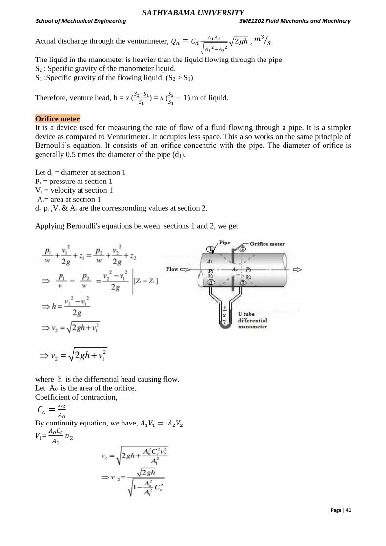
Orifice meter
It is a device used for measuring the rate of flow of a fluid flowing through a pipe. It is a simpler
device as compared to Venturimeter. It occupies less space. This also works on the same principle of
Bernoulli’s equation. It consists of an orifice concentric with the pipe. The diameter of orifice is
generally 0.5 times the diameter of the pipe (d1).
Let d1 = diameter at section 1
P1 = pressure at section 1
V1 = velocity at section 1
A1= area at section 1
d2, p2 ,V2 & A2 are the corresponding values at section 2.
Applying Bernoulli's equations between sections 1 and 2, we get
where h is the differential head causing flow.
Let Ao is the area of the orifice.
Coefficient of contraction,
𝐶𝑐 =𝐴2
𝐴𝑜
By continuity equation, we have, 𝐴1𝑉1 = 𝐴2𝑉2
𝑉1= 𝐴𝑜𝐶𝑐
𝐴1𝑣2

SATHYABAMA UNIVERSITY School of Mechanical Engineering SME1202 Fluid Mechanics and Machinery
Page | 42
If Cd is the co-efficient of discharge of orifice meter, which is defined as
Therefore, actual discharge through an orifice
Pitot tube
Pitot tube is a device used for measuring the velocity of flow at any point in a pipe or a channel.
Principle of working: If the velocity at any point decreases, the pressure at that point increases due to
the conservation of the kinetic energy into pressure energy.
In its simplest form, Pitot tube consists of a glass tube, bent at right angles with no capillary effect.
Let, p1 = pressure at section 1
p2 = pressure at section 2
V1 = velocity at section 1
V2= velocity at section 2 = 0
H = depth of tube in the liquid
h = rise of liquid in the tube above the free surface
Liquid at Point 1 is far away from the Pitot tube
Liquid at Point 2 is just at the inlet of the tube
h = h2 – h1 Liquid at Point 1 is far away from the Pitot tube
Liquid at Point 2 is just at the inlet of the tube
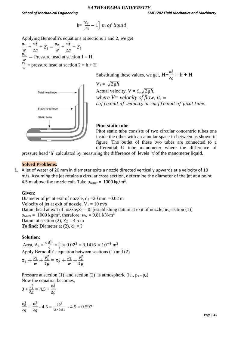
SATHYABAMA UNIVERSITY School of Mechanical Engineering SME1202 Fluid Mechanics and Machinery
Page | 43
h= [𝑆2
𝑆1− 1] 𝑚 𝑜𝑓 𝑙𝑖𝑞𝑢𝑖𝑑
Applying Bernoulli's equations at sections 1 and 2, we get 𝑝1
𝑤 +
𝑣12
2𝑔 + 𝑍1 =
𝑝2
𝑤 +
𝑣22
2𝑔 + 𝑍2
𝑝1
𝑤= Pressure head at section 1 = H
𝑝2
𝑤 = pressure head at section 2 = h + H
Substituting these values, we get, H+𝑣12
2𝑔 = h + H
V1 = √2𝑔ℎ
Actual velocity, V = 𝐶𝑣√2𝑔ℎ,
where V= velocity of flow, 𝐶𝑣 =𝑐𝑜𝑓𝑓𝑖𝑐𝑖𝑒𝑛𝑡 𝑜𝑓 𝑣𝑒𝑙𝑜𝑐𝑖𝑡𝑦 𝑜𝑟 𝑐𝑜𝑒𝑓𝑓𝑖𝑐𝑖𝑒𝑛𝑡 𝑜𝑓 𝑝𝑖𝑡𝑜𝑡 𝑡𝑢𝑏𝑒.
Pitot static tube Pitot static tube consists of two circular concentric tubes one
inside the other with an annular space in between as shown in
figure. The outlet of these two tubes are connected to a
differential U tube manometer where the difference of
pressure head ‘h’ calculated by measuring the difference of levels ‘x’of the manometer liquid.
Solved Problems:
1. A jet of water of 20 mm in diameter exits a nozzle directed vertically upwards at a velocity of 10 m/s. Assuming the jet retains a circular cross section, determine the diameter of the jet at a point 4.5 m above the nozzle exit. Take ρwater = 1000 kg/m3.
Given:
Diameter of jet at exit of nozzle, d1 =20 mm =0.02 m
Velocity of jet at exit of nozzle, V1 = 10 m/s
Datum head at exit of nozzle,Z1 = 0 [establishing datum at exit of nozzle, ie.,section (1)]
ρwater = 1000 kg/m3, therefore, ww = 9.81 kN/m3
Datum at section (2), Z2 = 4.5 m
To find: Diameter at (2), d2 = ?
Solution:
Area, A1 = 𝜋 𝑑1
2
4 =
𝜋
4× 0.022 = 3.1416 × 10⁻⁴ m2
Apply Bernoulli’s equation between sections (1) and (2)
𝑧1 +𝑝1
𝑤+
𝑣12
2𝑔 = 𝑧2 +
𝑝2
𝑤+
𝑣22
2𝑔
Pressure at section (1) and section (2) is atmospheric (ie., p1 = p2)
Now the equation becomes,
0 + 𝑣12
2𝑔 = 4.5 +
𝑣22
2𝑔
𝑣22
2𝑔 =
𝑣12
2𝑔 - 4.5 =
102
2×9.81 - 4.5 = 0.597

SATHYABAMA UNIVERSITY School of Mechanical Engineering SME1202 Fluid Mechanics and Machinery
Page | 44
V2 =√0.597 × 2 × 9.81 = 3.42 m/s
We know that, 𝐴1𝑉1 = 𝐴2𝑉2
A2 = 𝐴1𝑉1
𝑉2 =
3.1416×10⁻⁴
3.42× 10 = 9.186× 10⁻⁴ m2
Therefore, d2 = √9.186 × 10−4 ×4
𝜋 = 0.0342 m= 34.2 mm
2. A 250 mm diameter pipe carries oil of specific gravity 0.9 at a velocity of 3 m/s.At another section the diameter is 200 mm. Find the velocity at this section and the mass rate of flow of oil. Given: Diameter of pipe at section(1), d1 = 250 mm = 0.25 m;
Velocity of oil at section (1), V1 = 3 m/s
Diameter of pipe at section (2),d2 = 200 mm = 0.2 m;
specific gravity of oil flowing, S =0.9
To find: Velocity of oil at section (2), V2 = ?
Mass rate of flow of oil,m• = ?
Solution:
Density of the given oil, ρ = S × 𝜌𝑊 = 0.9 ×1000 = 900 kg/m³
By discharge continuity equation for steady incompressible flow, Q = 𝐴1𝑉1 = 𝐴2𝑉2
A1 = 𝜋 𝑑1
2
4 =
𝜋
4× 0.252 = 0.0499 m²
A2 = 𝜋 𝑑2
2
4 =
𝜋
4× 0.22 = 0.0314 m²
Volume flow rate or discharge, Q = 𝐴1𝑉1 = 0.0491 × 3 = 0.1473 m³/s
Mass rate of flow = ρQ = 900 × 0.1473 = 132.57 kg/m³ --------- Answer
Velocity of oil at section (2), V2 = 𝑄
𝐴2 =
0.1473
0.0314= 4.69 m/s ===== Answer
3. A liquid of specific gravity 1.3 flowing in a pipe at a rate of 800 litres per second upward from a section 1 with 60 cm diameter to an another section 2 of 30 cm diameter 1 m above. If the pressure at section 1 is 10 bar, determine the pressure at section 2.
Given: Flow rate, Q= 800 lit/s = 0.8 m3/s
Specific gravity of pipe liquid, S=1.3
𝑧2 − 𝑧1 = 1 m
Diameter at section (1), d1 = 60 cm = 0.6 m
Diameter at section (2), d2 = 30 cm = 0.3 m
Pressure at section (1), p1 = 10 bar = 1000 kN/m2
To find: Pressure at section (2), p2 = ?
Solution:
Specific weight of liquid, w = S x 𝑤w = 1.3 x 9.81 = 12.753 kN/m3
Area at section (1), A1 = π/4 x 0.62 = 0.28274 m2
Area at section (2), A2 = π/4 x 0.32 = 0.070686 m2
Velocity of liquid at section (1), V1 = 𝑄
𝐴1 =
0.8
0.28274 = 2.83 m/s

SATHYABAMA UNIVERSITY School of Mechanical Engineering SME1202 Fluid Mechanics and Machinery
Page | 45
Velocity of liquid at section (2), V2 = 𝑄
𝐴2 =
0.8
0.070686 = 11.32 m/s
Apply Bernoulli’s equation between sections (1) and (2)
𝑍1 +𝑝1
𝑤+
𝑣12
2𝑔 = 𝑍2 +
𝑝2
𝑤+
𝑣22
2𝑔
𝑝2
𝑤 = 𝑍1 − 𝑍2 +
𝑝1
𝑤 +
𝑣12
2𝑔 - 𝑣22
2𝑔 = -1 +
1000
12.753 +2.832−11.322
2 ×9.81 = 71.29
p2 = 71.29 x w = 71.29 x 12.753 = 909.16 kN/m2 = 9.09 bar
Pressure at section (2), p2 = 909.16 kN/m2 or 9.09 bar -----------Answer
4. While laying a water supply pipe line, the change in diameter of pipe was gradual from 200 mm at A to 500 mm at B. Pressure at A and B are 78.5 kN/m² and 58.9 kN/m² respectively with the end B being 3 m higher than A. If the flow in the pipe line is 200 lps, find: a) direction of flow and b) the head lost in friction between A and B. Given:Flow rate, Q= 200 lit/s = 0.2 m3/s
Specific gravity of pipe liquid, S=1 [water] Diameter at section (A), dA = 200 mm = 0.2 m Diameter at section (B), dB = 500 mm = 0.5 m Pressure at section (A), pA = 78.5 kN/m² Pressure at section (B), pB = 58.9 kN/m² 𝑧𝐵 − 𝑧𝐴 = 3 m
𝐓𝐨 𝐟𝐢𝐧𝐝: a) direction of flow and b) the head lost in friction between A and B, hL
Solution:
Area at inlet, AA = 𝜋
4𝑑𝐴2 =
𝜋
4× 0.22 = 0.031416 m2
Area at throat,AB = 𝜋
4𝑑𝐵2 =
𝜋
4× 0.5
2 = 0.19635 m2
By discharge continuity equation,
Velocity of liquid at section (A), VA = 𝑄
𝐴𝐴 =
0.2
0.031416 = 6.37 m/s
Velocity of liquid at section (B), VB = 𝑄
𝐴𝐵 =
0.2
0.19635 = 1.019 m/s
Applying Bernoulli's equation for real fluid flow between sections A and B,
𝑍𝐴 +𝑝𝐴
𝑤+
𝑣𝐴2
2𝑔 = 𝑍𝐵 +
𝑝𝐵
𝑤+
𝑣𝐵2
2𝑔 + hL
hL = 𝑍𝐴 +𝑝𝐴
𝑤+
𝑣𝐴2
2𝑔 - 𝑍𝐵 −
𝑝𝐵
𝑤−
𝑣𝐵2
2𝑔 =
𝑝𝐴
𝑤−
𝑝𝐵
𝑤 – (𝑍𝐵 + 𝑍𝐴) +
𝑣𝐴2
2𝑔−
𝑣𝐵2
2𝑔
= 78.5
9.81−
58.9
9.81 -3 +
6.372
2 ×9.81−
1.0192
2 ×9.81 = 8- 6 -3 + 2.068 – 0.053 = 1.015 m
The flow is always from high pressure side to low pressure side and hence from A to B.
SATHYABAMA UNIVERSITY School of Mechanical Engineering SME1202 Fluid Mechanics and Machinery
Page | 46
5. A pipe 400 mm diameter carries water at a velocity of 2.5 m/s. The pressure head at points A and B are given as 30 m and 23 m respectively, while the datum head at A and B are 28 m and 30 m respectively. Find the loss of head between A and B. Given:
Diameter of pipe, dA = dB = 400 mm = 0.4 m
Velocity of Water, VA = VB = 2.5 m/s
Pressure head at A, 𝑝𝐴
𝑤 = 30 m
Pressure head at B, 𝑝𝐵
𝑤 = 23 m
Datum head at A, 𝑍𝐴 = 28 m
Datum head at B, 𝑍𝐵 = 30 m
To find: Loss of head =?
Solution:
Velocity head at A, 𝑣𝐴2
2𝑔= Velocity head at B,
𝑣𝐵2
2𝑔 =
2.52
2×9.81 = 0.3186 m
Total head at A = 𝑍𝐴 +𝑝𝐴
𝑤+
𝑣𝐴2
2𝑔 = 28 + 30 + 0.3186 = 58.3186 m
Total head at B = 𝑍𝐵 +𝑝𝐵
𝑤+
𝑣𝐵2
2𝑔 = 30 + 23+ 0.3186 = 53.3186 m
Loss of head = Total head at A - Total head at B = 58.3186 – 53.3186 = 5 m ---------Answer
6. An oil of sp. gr. 0.8 is flowing through a venturimeter having inlet diameter 20 cm and throat diameter 10cm. The oil-mercury differential manometer shows a reading of 25 cm. Calculate the discharge of oil through the horizontal venturimeter. Take Cv=0.98. Given: Diameter at inlet, d1 = 20 cm = 0.2 m
Diameter at throat, d2 = 10 cm = 0.1 m
Manometer deflection, x = 25 cm = 0.25 m
Specific gravity of oil flowing, S1 = 0.8
Specific gravity of manometer liquid (mercury), S2 = 13.6
Cv = 0.98
To find: discharge of oil through the horizontal Venturimeter, Qa
Solution:
Area at inlet, A1 = 𝜋
4𝑑12 =
𝜋
4× 0.22 = 0.031416 m2
Area at throat,A2 = 𝜋
4𝑑22 =
𝜋
4× 0.1
2 = 0.007854 m2
Venturi head, h = 𝑥 (𝑆2
𝑆1− 1) = 0.25(
13.6
0.8− 1) = 4 m
Actual discharge through Venturimeter, 𝑄𝑎 = 𝐶𝑑𝐴1𝐴2
√𝐴12−𝐴2
2√2𝑔ℎ
= 0.98×0.031416×0.007854
√0.0314162−0.0078542 √2 × 9.81 × 4
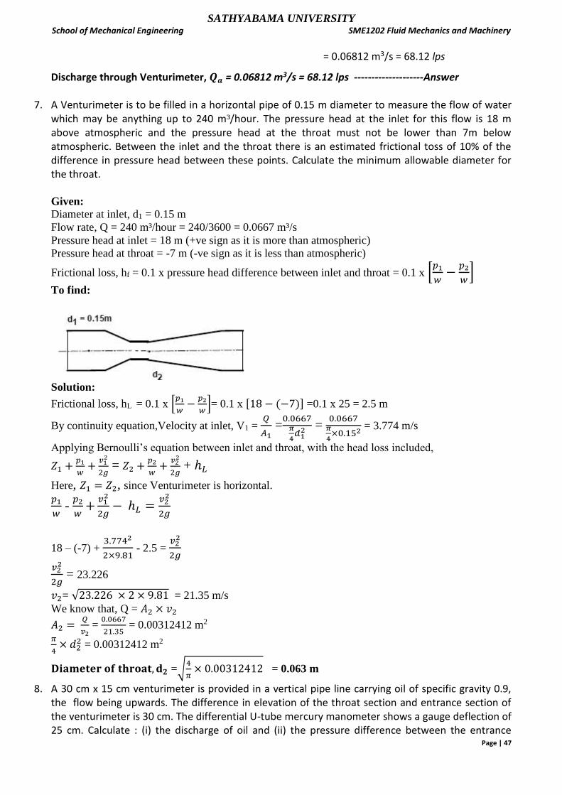
SATHYABAMA UNIVERSITY School of Mechanical Engineering SME1202 Fluid Mechanics and Machinery
Page | 47
= 0.06812 m3/s = 68.12 lps
Discharge through Venturimeter, 𝑸𝒂 = 0.06812 m3/s = 68.12 lps --------------------Answer
7. A Venturimeter is to be filled in a horizontal pipe of 0.15 m diameter to measure the flow of water which may be anything up to 240 m³/hour. The pressure head at the inlet for this flow is 18 m above atmospheric and the pressure head at the throat must not be lower than 7m below atmospheric. Between the inlet and the throat there is an estimated frictional toss of 10% of the difference in pressure head between these points. Calculate the minimum allowable diameter for the throat. Given:
Diameter at inlet, d1 = 0.15 m
Flow rate, Q = 240 m³/hour = 240/3600 = 0.0667 m³/s
Pressure head at inlet = 18 m (+ve sign as it is more than atmospheric)
Pressure head at throat = -7 m (-ve sign as it is less than atmospheric)
Frictional loss, hf = 0.1 x pressure head difference between inlet and throat = 0.1 x [𝑝1
𝑤−
𝑝2
𝑤]
To find:
Solution:
Frictional loss, hL = 0.1 x [𝑝1
𝑤−
𝑝2
𝑤]= 0.1 x [18 − (−7)] =0.1 x 25 = 2.5 m
By continuity equation,Velocity at inlet, V1 = 𝑄
𝐴1 =0.0667𝜋
4𝑑12 =
0.0667𝜋
4×0.152
= 3.774 m/s
Applying Bernoulli’s equation between inlet and throat, with the head loss included,
𝑍1 +𝑝1
𝑤+
𝑣12
2𝑔 = 𝑍2 +
𝑝2
𝑤+
𝑣22
2𝑔 + ℎ𝐿
Here, 𝑍1 = 𝑍2, since Venturimeter is horizontal.
𝑝1
𝑤 -
𝑝2
𝑤+
𝑣12
2𝑔− ℎ𝐿 =
𝑣22
2𝑔
18 – (-7) + 3.7742
2×9.81 - 2.5 =
𝑣22
2𝑔
𝑣22
2𝑔 = 23.226
𝑣2= √23.226 × 2 × 9.81 = 21.35 m/s
We know that, Q = 𝐴2 × 𝑣2
𝐴2 = 𝑄
𝑣2 =
0.0667
21.35 = 0.00312412 m2
𝜋
4× 𝑑2
2 = 0.00312412 m2
𝐃𝐢𝐚𝐦𝐞𝐭𝐞𝐫 𝐨𝐟 𝐭𝐡𝐫𝐨𝐚𝐭, 𝐝𝟐 =√4
𝜋× 0.00312412 = 0.063 m
8. A 30 cm x 15 cm venturimeter is provided in a vertical pipe line carrying oil of specific gravity 0.9, the flow being upwards. The difference in elevation of the throat section and entrance section of the venturimeter is 30 cm. The differential U-tube mercury manometer shows a gauge deflection of 25 cm. Calculate : (i) the discharge of oil and (ii) the pressure difference between the entrance
SATHYABAMA UNIVERSITY School of Mechanical Engineering SME1202 Fluid Mechanics and Machinery
Page | 48
section and the throat section. Take the coefficient of discharge as 0.98 and specific gravity of mercury as 13.6. Given:
Dia. at inlet,d1 = 30 cm = 0.3 m
Dia. at throat,d2 = 15 cm = 0.15 m
Specific gravity of oil, S1 = 0.9
Specific gravity of manometer liquid (mercury),S2 = 13.6
Difference between the entrance section and the throat section, z2-z1 = 30 cm = 0.3 m
Manometer deflection, x = 25 cm = 0.25 m.
Coefficient of discharge, Cd = 0.98
To find:
(i) the discharge of oil, Qa =? and (ii) the pressure difference between the entrance section and
the throat section, p1-p2= ?
Solution:
.Area at inlet, A1 = 𝜋
4𝑑12 =
𝜋
4× 0.32 = 0.0707 m2
Area at throat,A2 = 𝜋
4𝑑22 =
𝜋
4× 0.15
2 = 0.01767 m2
Venturi head, h = 𝑥 (𝑆2
𝑆1− 1) = 0.25(
13.6
0.9− 1) = 3.528 m
Actual discharge through Venturimeter, 𝑄𝑎 = 𝐶𝑑𝐴1𝐴2
√𝐴12−𝐴2
2√2𝑔ℎ
= 0.98×0.0707×0.01767
√0.07072−0.017672 √2 × 9.81 × 3.528 = 0.1488 m³/s
Pressure head difference between inlet and throat section, h =
(𝑍1 +𝑝1
𝑤) - ( 𝑍2 +
𝑝2
𝑤) = 3.528
( 𝑍1 − 𝑍2) + 𝑝1
𝑤−
𝑝2
𝑤 = 3.528
𝑝1
𝑤−
𝑝2
𝑤 = 3.528 - ( 𝑍1 − 𝑍2) = 3.528 + ( 𝑍2 − 𝑍1) = 3.528 + 0.3 = 3.828 m
Pressure difference between the entrance and the throat,
𝑝1 − 𝑝2 = w× 3.828 = 9.81 × 3.828 =37.553 kN/m² ----------------------Answer
9. A pitot tube is used to measure the flow of a liquid in a pipe line. The two tapping of the pitot tube are connected to a differential U-tube manometer. If the manometric liquid is mercury and the differential mercury level is 12 cm, what is the velocity? Take RD of turpentine = 0.86. The coefficient of the pitot tube is 0.975. Given: Manometer deflection, x = 12 cm of mercury = 0.12 m
Cv = 0.975
S2 is the relative density of Manometric liquid = 13.6
S1 is the relative density of flowing fluid = 0.86
To find:
Velocity of flow = ?
Solution:

SATHYABAMA UNIVERSITY School of Mechanical Engineering SME1202 Fluid Mechanics and Machinery
Page | 49
Head causing flow, h = 𝑥 (𝑆2
𝑆1− 1) = 0.12 × (
13.6
0.86 -1) = 1.772 m
Velocity of liquid, V = Cv√2𝑔ℎ
= 0.975 ×(2 x 9.81 × l.772)
Velocity of liquid, V = 5.75 m/s ------------------------------Answer
10. A 45° degree bend is connected in a pipe line, the diameters at the inlet and outlet of the bend being 600 mm and 300 mm respectively. Find the force exerted by water on the bend if intensity of pressure at inlet to bend is 88.29 kN/m² and rate of flow of water is 0.6 m³/s.
Given:
Angle of pipe bend, α2 = 45°
Pipe bend is in horizontal plane(view is plan). Therefore at inlet section, α1 =0
Diameter at the inlet, d1 = 600 mm = 0.6 m
Diameter at outlet, d2= 300 mm = 0.3 m
Pressure at inlet, p1= 88.29 kN/m²
Flow rate, Q = 0.6 m³/s
To find:
Force exerted by water on the bend = ?
Solution:
Area of section (1), A1 = 𝜋
4 𝑑1
2 = 𝜋
4 × 0.6
2 =0.2827 m²
Area of section (2), A2 = 𝜋
4 𝑑2
2 = 𝜋
4 × 0.3
2 =0.0707 m²
Density of water,ρ =1000 kg/m³
Velocity at section (1), V1 = 𝑄
𝐴1 = 0.6/0.2827 =2.122 m/s
Velocity at section (2), V2 = 𝑄
𝐴2 = 0.6/0.0707 = 8.487 m/s
Applying Bernoulli’s equation between Sections 1 and 2,
𝑍1 +𝑝1
𝑤+
𝑣12
2𝑔 = 𝑍2 +
𝑝2
𝑤+
𝑣22
2𝑔
Since pipe bend lie in a horizontal plane, Z1 = Z2
••• 𝑝2
𝑤 = [
𝑝1
𝑤+
𝑣12
2𝑔−
𝑣22
2𝑔]
••• p2 = 𝑤 [ 𝑝1𝑤+
𝑣12
2𝑔−
𝑣22
2𝑔] = 9.81 × [
88.29
9.81+
2.1222
2×9.81 –
8.4872
2×9.81] = 54.5269 kN/m² =54526.9 N/m²

SATHYABAMA UNIVERSITY School of Mechanical Engineering SME1202 Fluid Mechanics and Machinery
Page | 50
Net Force along 𝑥 axis, 𝑭𝒙 = 𝝆𝑸(𝒗𝟏 − 𝒗𝟐𝒄𝒐𝒔𝜶𝟐) + 𝑨𝟏𝒑𝟏 − 𝑨𝟐𝒑𝟐𝒄𝒐𝒔𝜶𝟐
••• 𝑭𝒙 = 1000× 0.6 × (2.122 − 8.487 × 𝑐𝑜𝑠45) + 0.2827 × 88290 −0.0707 × 54526.9 × cos 45
= -2327.5+24959.6-2725.9 = 19906.2 N
Net Force along y axis, 𝑭𝒚 = 𝝆𝑸(−𝒗𝟐𝒔𝒊𝒏𝜶𝟐) − 𝑨𝟐𝒑𝟐𝒔𝒊𝒏𝜶𝟐
••• 𝑭𝒚 = 1000 × 0.6 × (−8.487 × sin 45) − 0.0707 × 54526.9 × sin 45 = - 6326.7 N
Resultant force acting on the pipe bend, 𝐹 = √𝐹𝑥2 + 𝐹𝑦2 = √19906.2² + (−6326.7)² = 20887.4 N
= 20.887 kN
Direction of the resultant force on the pipe bend,
θ = tan−1 (𝐹𝑦
𝐹𝑥) = tan−1[
6326.7
19906.2] = 17.63° from horizontal
11. An orifice meter with orifice diameter 15 cm is inserted in a pipe of 30 cm diameter. The pressure gauges fitted upstream and downstream of the orifice meter give readings of 14.715 N/cm² and 9.81 N/cm² respectively. Find the rate of flow of water through the pipe in lit/s. Take Cd = 0.6. Given:
Dia. at inlet, d1 = 30 cm = 0.3 m Dia. at orifice,d2 = 15 cm = 0.15 m Specific gravity of water, S1 = 1 Coefficient of discharge, Cd = 0.6 Pressure at inlet, p1 = 14.715 N/cm² = 147.15 kN/m² Pressure at inlet, p2 = 9.81N/cm² = 98.1 kN/m² To find: Rate of flow, Qa =?
Area at inlet, A1 = 𝜋
4𝑑12 =
𝜋
4× 0.32 = 0.0707 m2
Area at orifice, Ao = 𝜋
4𝑑22 =
𝜋
4× 0.15
2 = 0.01767 m2
Pressure difference between inlet and orifice = p1-p2 = 147.15 - 98.1= 49.05 kN/ m²
Head causing flow, h = p1−p2
𝑤 = 49.05/9.81 = 5 m of water
Rate of flow,
Qa = 0.6 ×0.01767× 0.0707√2×9.81×5
√0.07072−0.017672 = 0.1084 m³/s
= 108.4 l/s --------------------------------Ans
Questions for practice
1. Define Control Volume and control surface continuity equation, Rate of Flow
2. List the types of fluid flow.
3. Define Steady and Unsteady flow.
4. Define Uniform and Non-uniform flow.

SATHYABAMA UNIVERSITY School of Mechanical Engineering SME1202 Fluid Mechanics and Machinery
Page | 51
5. Compare Laminar and Turbulent flow.
6. What is the variation of viscosity with temperature for fluids? 7. Define Compressible and incompressible flow
8. Define Rotational and Irrotational flow.
9. Define One, Two and Three dimensional flow.
10. State the Bernoulli’s equation and its applications.
11. State the assumptions used in deriving Bernoulli’s equation.
12. State Momentum Equation.
13. What is the use of an orifice meter?
14. What is the use of a Venturimeter?
15. State the difference between Venturimeter and Orificemeter.
16. What is the use of Pitot tube?
Part B
1. Derive Euler’s equation of motion along the stream line for an ideal fluid and thereby deduce
Bernoulli’s equation stating clearly the assumptions
2. What is venturimeter? Derive an expression for the discharge through a venturimeter.
3. Derive differential form of continuity equation.
4. Differentiate between Venturimeter and Orificemeter.
5. water is flowing through a pipe having diameters 20 cm and 15 cm at sections 1 and 2 respectively. The rate of flow through pipe is 40 liters/sec. The section 1 is 6m above datum line and section 2 is 3 m above the datum. If pressure at section 1 is 29.43 N/cm2, find the intensity of pressure at section 2.
6. An oil of sp. gr. 0.8 is flowing through a venturimeter having inlet diameter 20 cm and throat
diameter 10cm. The oil-mercury differential manometer shows a reading of 25 cm. Calculate
the discharge of oil through the horizontal venturimeter. Take Cv=0.98.
7. A 300mm diameter pipe carries water under a head of 20m with a velocity of 3.5 m/s. If the axis
of the pipe turns through 450, find the magnitude and direction of resultant force at the bend.
8. An orifice meter with orifice diameter 10 cm is inserted in a pipe of 20 cm diameter. The
pressure gauges fitted on upstream and downstream of the orifice meter give readings of 19.62
N/cm2 and 9.81 N/cm2 respectively. Co-efficient of discharge for the meter is 0.6. Find the
discharge of water through the pipe.
9. A horizontal venturimeter with inlet and throat diameter 300mm and 100mm respectively is used
to measure the flow of water. The pressure intensity at inlet is 130KN/m2 while the vacuum
pressure head at throat is 350mm of mercury. Assuming 3% head lost between inlet and the
throat find the value of co-efficient of discharge for the venturimeter and also determine the rate
of flow.
10. A pipe of 300 mm diameter inclined at 30° to the horizontal is carrying gasoline (specific gravity
=0.82). A Venturimeter is fitted in the pipe to find out the flow rate whose throat diameter is 150
mm. The throat is 1.2 m from the entrance along its length. The pressure gauges fitted to the
Venturimeter read 140 kN/m² and 80 kN/m² respectively. Find out the coefficient of discharge
of Venturimeter if the flow is 0.20 m³/s.
11. Find the velocity of flow of an oil through a pipe when the difference of mercury level in a
differential U tube manometer connected to the two tappings of pitot tube is 10cm.Take the co-

SATHYABAMA UNIVERSITY School of Mechanical Engineering SME1202 Fluid Mechanics and Machinery
Page | 52
efficient of of pitot tube as 0.98and Soil is 0.8.Find the discharge through the pipe if the diameter is
30 cm.
12. Water is flowing through a pipe having diameters 20 cm and 15 cm at sections 1 and 2 respectively. The rate of flow through pipe is 40 liters/sec. The section 1 is 6m above datum line and section 2 is 3 m above the datum. If pressure at section 1 is 29.43 N/cm2, find the intensity of pressure at section 2.
13. Water flows upwards in a vertical pipe line of gradually varying section from point 1 to point 2,
which is 1.5m above point 1, at the rate of 0.9 m³/s. At section 1 the pipe dia is 0.5m and pressure is 300 kPa. If pressure at section 2 is 600 kPa, determine the pipe diameter at that location. Neglect losses.
14. Water flows up a conical pipe 450 mm diameter at the lower end and 250 mm diameter at 2.3 m above the lower end. If the pressure and velocity at the lower end are 63 kN/m² (gauge) and 4.1 m/s, assuming a head loss in the pipe to be 10% of the pressure head at the lower end, calculate the discharge through the pipe. Also calculate the pressure and velocity at the upper end.
15. Water is flowing through a tapering pipe of length 200 m having diameters 500 mm at the
upper end and 250 mm at the lower end, the pipe has a slope of 1 in 40. The rate of flow through the pipe is 250 lit/ sec. the pressure at the lower end and the upper end are 20 N/cm² and 10 N/cm² respectively. Find the loss of head and direction of flow.
16. Water at 36 m above sea level has a velocity of 18 m/s and a pressure of 350 kN/m². Determine the potential, kinetic and pressure energy of the water in metres of head. Also determine the total head.
17. A liquid with specific gravity 0.8 flows at the rate of 3 l/s through a venturimeter of diameters 6 cm and 4 cm. If the manometer fluid is mercury, determine the value of manometer reading.