satellar digital system part ii: central unit user guide version 1
TRANSCRIPT
2
SATELLAR DIGITAL SYSTEMPART II: CENTRAL UNITUSER GUIDE VERSION 1.2
WIRELESS WORLD – LOCAL SOLUTION
CUUSER GUIDE

Copyright: 2012 SATEL Oy
No part of this document may be reproduced, transmitted or stored in a retrieval system in any form or by any means without the prior written permission of SATEL Oy. This document is provided in confi dence and must not be distributed to third parties without the express permission of SATEL Oy.
3SATEL OY // SATELLAR MANUAL // PART II // CENTRAL UNIT // USER GUIDE // V. 1.2
2
Contents
Important notice 7
Product conformity 8
Warranty and safety instructions 9
1. Introduction to the SATELLAR product family 10
1.1 Mounting 14
2. Technical specifi cations 18
3. Typical setup 19
4. Mechanical assembly, modular construction 20
5. Interfaces 22
5.1 Ethernet 23
5.2 USB 23
5.3 Diagnostics, monitoring, changing settings 23
5.4 LED indicators 24
5.5 Function button 25
5.6 Graphical user interface 275.6.1 Booting screen 275.6.2 LCD display, information and button menu areas 285.6.3 Main menu 295.6.4 Status screen 295.6.5 Screen save mode 30
4 SATEL OY // SATELLAR MANUAL // PART II // CENTRAL UNIT // USER GUIDE // V. 1.2
2
5.7 WWW User interface 305.7.1 Login 305.7.2 Main menu 305.7.3 Status area 315.7.4 Categories list 315.7.5 Category page 325.7.6 Changing settings 32
5.8 SATEL NMS 33
5.9 SSH 33
6. Data transmission 34
6.1 Internet protocol 346.1.1 Example 346.1.2 Forming the tun0 IP address 366.1.3 Choosing the eth0 IP address 366.1.4 Setting IP routes 37
6.2 DHCP 38
7. Settings 39
7.1 Modem Settings 397.1.1 Radio Unit Settings categories 397.1.2 General 397.1.3 Services 417.1.4 Commands 427.1.5 Remote Devices 447.1.6 Time Control 45
7.2 Modem Info 457.2.1 Status 467.2.2 Radio Unit 477.2.3 Central Unit 48
7.3 Routing 497.3.1 Packet Routing Tables 507.3.2 IP 507.3.3 IP Routes 52
5SATEL OY // SATELLAR MANUAL // PART II // CENTRAL UNIT // USER GUIDE // V. 1.2
2
7.4 Serial IP 567.4.1 Serial IP RS-232 / USB-A 567.4.2 Examples 587.4.3 UDP and TCP protocols 647.4.4 Notes 65
8. Applications 67
8.1 Diagnostics 67
8.2 Simple Network Management Protocol (SNMP) 698.2.1 SNMP category 718.2.2 MIB 72
8.3 Firmware updating 738.3.1 Firmware updater application 738.3.2 USB Stick during boot CU update method 778.3.3 Firmware update over-the-air 77
8.4 Remote settings 82
8.5 NMS Import 838.5.1 Exporting settings from modem 838.5.2 NMS Export advanced features 848.5.3 The export/import fi le contents 848.5.4 Managing export fi les 858.5.5 Importing settings to a modem 86
8.6 Encryption 87
8.7 Logs 88
8.8 Administration 888.8.1 General 898.8.2 IP 89
9. Type designation 90
10. Troubleshooting 91
10.1 Error codes 91
6 SATEL OY // SATELLAR MANUAL // PART II // CENTRAL UNIT // USER GUIDE // V. 1.2
2
11. SATEL open source statements 93
11.1 LGPL and GPL software 93
11.2 Written offer for LGPL and GPL source code 93
12. Settings selection guide 94
12.1 Modem Settings 94
12.2 Routing 97
12.3 Administration 98
7SATEL OY // SATELLAR MANUAL // PART II // CENTRAL UNIT // USER GUIDE // V. 1.2
2All rights to this manual are owned solely by SATEL OY (referred to in this user guide as SATEL). All rights reserved. The copying of this manual (without written permission from the owner) by printing, copying, recording or by any other means, or the full or partial translation of the manual to any other language, including all programming languages, using any electrical, mechanical, magnetic, optical, manual or other methods or devices is forbidden.
SATEL reserves the right to change the technical specifi cations or functions of its products, or to discontinue the manufacture of any of its prod-ucts or to discontinue the support of any of its products, without any written announcement and urges its customers to ensure that the information at their disposal is valid.
SATEL software and programs are delivered ”as is”. The manufacturer does not grant any kind of warranty including guarantees on suitability and
applicability to a certain application. Under no circumstances is the manufacturer or the devel-oper of a program responsible for any possible damages caused by the use of a program. The names of the programs as well as all copyrights relating to the programs are the sole property of SATEL. Any transfer, licensing to a third party, leasing, renting, transportation, copying, editing, translating, modifying into another programming language or reverse engineering for any intent is forbidden without the written consent of SATEL.
SATEL PRODUCTS HAVE NOT BEEN DESIGNED, INTENDED NOR INSPECTED TO BE USED IN ANY LIFE SUPPORT - RELATED DEVICE OR SYSTEM - RELATED FUNCTION NOR AS A PART OF ANY OTHER CRITICAL SYSTEM AND ARE GRANTED NO FUNCTIONAL WARRANTY IF THEY ARE USED IN ANY OF THE APPLICATIONS MENTIONED.
Salo, Finland 2012
Important notice
8 SATEL OY // SATELLAR MANUAL // PART II // CENTRAL UNIT // USER GUIDE // V. 1.2
2
Product conformity
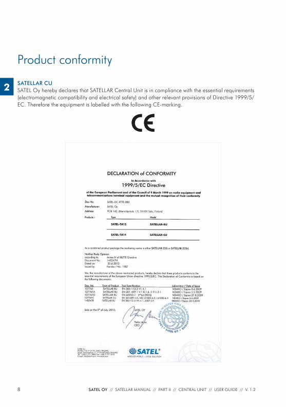
SATELLAR CUSATEL Oy hereby declares that SATELLAR Central Unit is in compliance with the essential requirements (electromagnetic compatibility and electrical safety) and other relevant provisions of Directive 1999/5/EC. Therefore the equipment is labelled with the following CE-marking.
9SATEL OY // SATELLAR MANUAL // PART II // CENTRAL UNIT // USER GUIDE // V. 1.2
2
Warranty and safety instructions
Read these safety instructions carefully before using the product:
– The warranty will be void if the product is used in any way that is in contradiction with the instructions given in this manual, or if the housing of the radio modem has been opened or tampered with.
– The devices mentioned in this manual are to be used only according to the instructions described in this manual. Faultless and safe operation of the devices can be guaranteed only if the transport, storage, operation and handling of the device is appropriate. This also applies to the maintenance of the products.
– To prevent damage the Central Unit (referred to in this user guide as CU) must always be switched OFF before connecting or disconnecting the serial connection cable. It should be ascertained that different devices used have the same ground potential. Before connecting any power cables the output voltage of the power supply should be checked.
10 SATEL OY // SATELLAR MANUAL // PART II // CENTRAL UNIT // USER GUIDE // V. 1.2
1. Introduction to the SATELLAR product family
2
1. Introduction to the SATELLAR product family
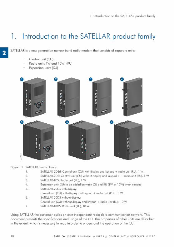
SATELLAR is a new generation narrow band radio modem that consists of separate units:
– Central unit (CU) – Radio units 1W and 10W (RU) – Expansion units (XU)
Figure 1.1 SATELLAR product family:1. SATELLAR-2DSd: Central unit (CU) with display and keypad + radio unit (RU), 1 W2. SATELLAR-2DS: Central unit (CU) without display and keypad + + radio unit (RU), 1 W3. SATELLAR-1DS: Radio unit (RU), 1 W4. Expansion unit (XU) to be added between CU and RU (1W or 10W) when needed5. SATELLAR-20DS with display: Central unit (CU) with display and keypad + radio unit (RU), 10 W6. SATELLAR-20DS without display: Central unit (CU) without display and keypad + radio unit (RU), 10 W7. SATELLAR-10DS: Radio unit (RU), 10 W
Using SATELLAR the customer builds an own independent radio data communication network. This document presents the specifi cations and usage of the CU. The properties of other units are described in the extent, which is necessary to read in order to understand the operation of the CU.
11SATEL OY // SATELLAR MANUAL // PART II // CENTRAL UNIT // USER GUIDE // V. 1.2
1. Introduction to the SATELLAR product family
2
Data communicationSATELLAR operates either as a transparent radio link, essentially replacing a wire, for classic RS-232, RS-485 or RS-422 based protocols, or as a wireless router in an IP-based network. Using SATELLAR many network topologies are possible, everything from a point-to-point connection to a nationwide chain with multiple branches.
RangeWith SATELLAR the communication range of a point to point link is typically longer than 10 km in urban conditions (some obstacles in the line of sight), and longer than 20 km in ideal line of sight conditions. The range can be further extended using high gain antennas, booster modules and radio repeaters.
SecurityData security is often a concern when using radio communication. In SATELLAR a 128-bit encryption on the air-interface ensures privacy in the radio network.
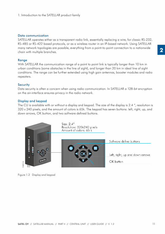
Display and keypadThe CU is available with or without a display and keypad. The size of the display is 2.4 “, resolution is 320 x 240 pixels, and the amount of colors is 65k. The keypad has seven buttons: left, right, up, and down arrows, OK button, and two software defi ned buttons.
Figure 1.2 Display and keypad
12 SATEL OY // SATELLAR MANUAL // PART II // CENTRAL UNIT // USER GUIDE // V. 1.2
1. Introduction to the SATELLAR product family
2
Diagnostics and confi gurationRadio modems are often used in applications where reliability and independence are key properties. To support this demand, SATELLAR has built-in diagnostic and remote confi guration features.
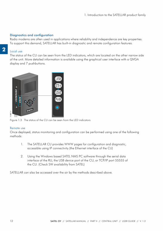
Local useThe status of the CU can be seen from the LED indicators, which are located on the other narrow side of the unit. More detailed information is available using the graphical user interface with a QVGA display and 7 pushbuttons.
Remote useOnce deployed, status monitoring and confi guration can be performed using one of the following methods:
1. The SATELLAR CU provides WWW pages for confi guration and diagnostic, accessible using IP connectivity (the Ethernet interface of the CU)
2. Using the Windows based SATEL NMS PC software through the serial data interface of the RU, the USB device port of the CU, or TCP/IP port 55555 of the CU. (Check SW availability from SATEL)
SATELLAR can also be accessed over the air by the methods described above.
Figure 1.3 The status of the CU can be seen from the LED indicators
13SATEL OY // SATELLAR MANUAL // PART II // CENTRAL UNIT // USER GUIDE // V. 1.2
1. Introduction to the SATELLAR product family
2
Flexible and expandableSATELLAR concept has been designed to be fl exible and expandable both in terms of hardware and software functions.
SoftwareIn the RU the modulation method, channel spacing (i.e. air interface data rate), and forward error correction can be selected by changing the modem settings by software. Also the RF output power can be set.
HardwareDue to the modular mechanical structure of SATELLAR, it is possible to add hardware expansion units. The idea is that this could be done as an update after the initial deployment. At the moment, however, the RU does not support the update. Schedule for this will be informed later.
USB host and device connectors offer a possibility to connect commercially available USB devices like Bluetooth and WLAN modules to the modem or e.g. to show the modem as an external memory device to the PC.
RuggedizedSATELLAR is constructed of die-cast aluminum to withstand the abuse typical to rough industrial envi-ronments. It operates over a wide temperature range and under severe vibration conditions to meet the requirements of vehicular and process industry applications.
14 SATEL OY // SATELLAR MANUAL // PART II // CENTRAL UNIT // USER GUIDE // V. 1.2
1. Introduction to the SATELLAR product family
2
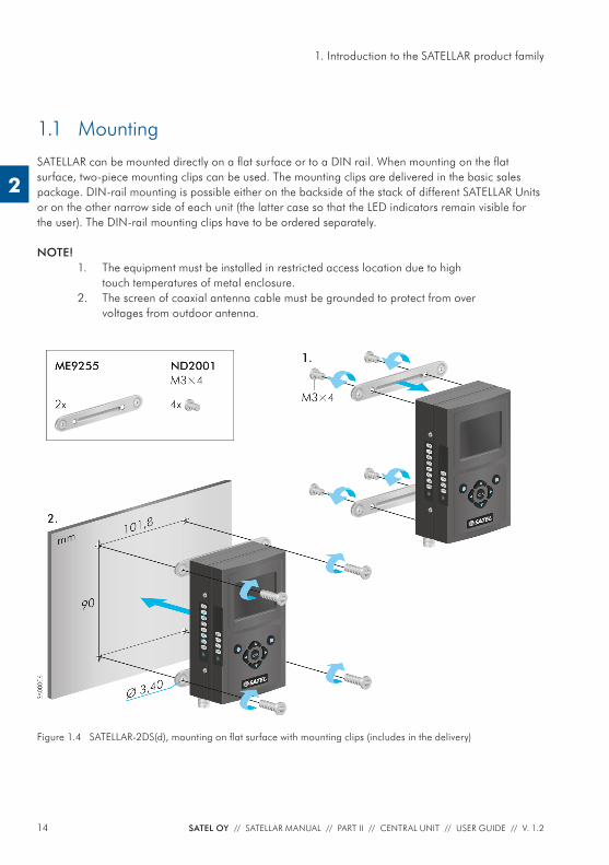
1.1 MountingSATELLAR can be mounted directly on a fl at surface or to a DIN rail. When mounting on the fl at surface, two-piece mounting clips can be used. The mounting clips are delivered in the basic sales package. DIN-rail mounting is possible either on the backside of the stack of different SATELLAR Units or on the other narrow side of each unit (the latter case so that the LED indicators remain visible for the user). The DIN-rail mounting clips have to be ordered separately.
Figure 1.4 SATELLAR-2DS(d), mounting on fl at surface with mounting clips (includes in the delivery)
NOTE!1. The equipment must be installed in restricted access location due to high
touch temperatures of metal enclosure.2. The screen of coaxial antenna cable must be grounded to protect from over
voltages from outdoor antenna.
15SATEL OY // SATELLAR MANUAL // PART II // CENTRAL UNIT // USER GUIDE // V. 1.2
1. Introduction to the SATELLAR product family
2
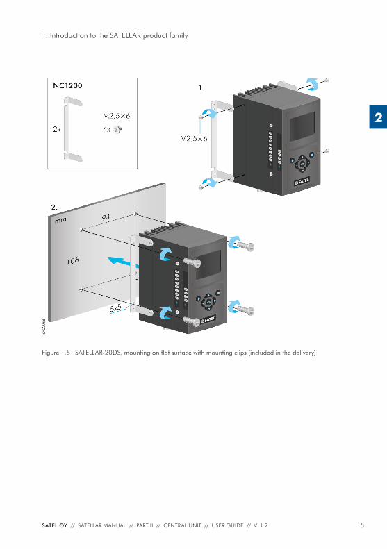
Figure 1.5 SATELLAR-20DS, mounting on fl at surface with mounting clips (included in the delivery)
16 SATEL OY // SATELLAR MANUAL // PART II // CENTRAL UNIT // USER GUIDE // V. 1.2
1. Introduction to the SATELLAR product family
2
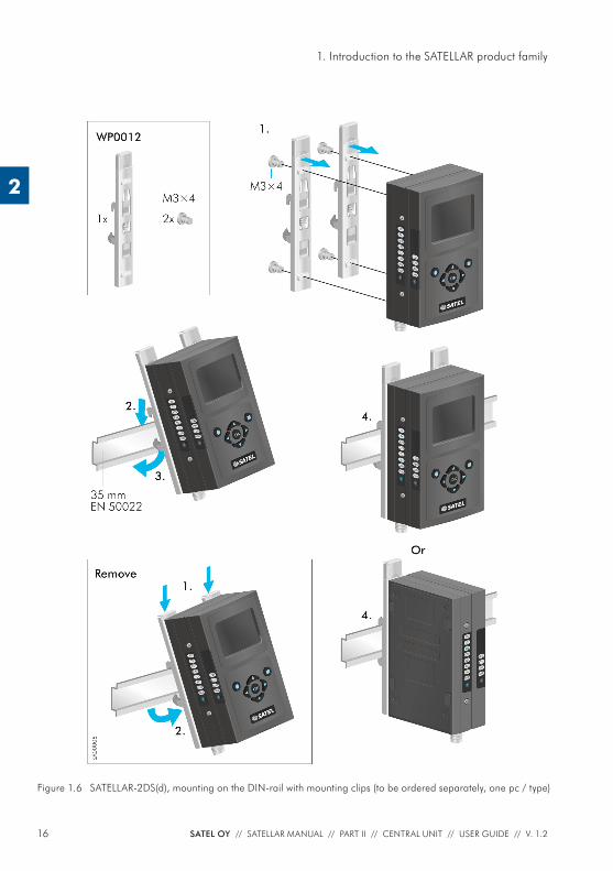
Figure 1.6 SATELLAR-2DS(d), mounting on the DIN-rail with mounting clips (to be ordered separately, one pc / type)
17SATEL OY // SATELLAR MANUAL // PART II // CENTRAL UNIT // USER GUIDE // V. 1.2
1. Introduction to the SATELLAR product family
2
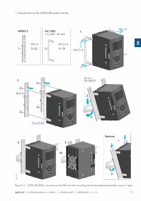
Figure 1.7 SATELLAR-20DS, mounting on the DIN-rail with mounting clips (to be ordered separately, one pc / type)
18 SATEL OY // SATELLAR MANUAL // PART II // CENTRAL UNIT // USER GUIDE // V. 1.2
2. Technical specifi cations
2
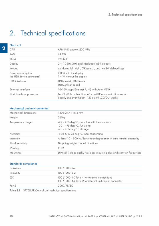
2. Technical specifi cations
Electrical
CPU ARM 9 @ approx. 200 MHz
RAM 64 MB
ROM 128 MB
Display 2.4 ”, 320 x 240 pixel resolution, 65 k colours
Keypad up, down, left, right, OK (select), and two SW defi ned keys
Power consumption (no USB device connected)
2.0 W with the display1.4 W without the display
USB interfaces USB-host & USB-deviceUSB2.0 high speed
Ethernet interface 10/100 Mbps Ethernet RJ-45 with Auto-MDIX
Start time from power on For CU/RU combination: 65 s until IP communication works (locally and over the air). 130 s until LCD/GUI works.
Mechanical and environmental
Mechanical dimensions 130 x 21.7 x 76.5 mm
Weight 260 g
Temperature ranges -25 - +55 deg °C, complies with the standards-30 - +75 deg °C, functional-40 - +85 deg °C, storage
Humidity < 95 % @ 25 deg °C, non-condensing
Vibration At least 10 – 500 Hz/5g without degradation in data transfer capability
Shock resistivity Dropping height 1 m, all directions
IP rating IP 52
Mounting: DIN rail (side or back), two piece mounting clip, or directly on fl at surface
Standards compliance
Emissions IEC 61600-6-4
Immunity IEC 61000-6-2
ESD IEC 61000-4-2 level 4 for external connectionsEIC 61000-4-2 level 2 for internal unit-to-unit connector
RoHS 2002/95/EC
Table 2.1 SATELLAR Central Unit technical specifi cations
19SATEL OY // SATELLAR MANUAL // PART II // CENTRAL UNIT // USER GUIDE // V. 1.2
3. Typical setup
2
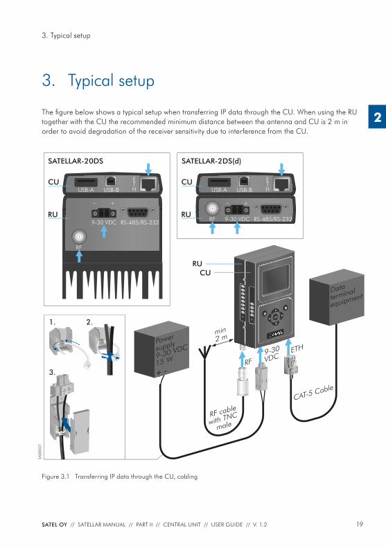
3. Typical setup
The fi gure below shows a typical setup when transferring IP data through the CU. When using the RU together with the CU the recommended minimum distance between the antenna and CU is 2 m in order to avoid degradation of the receiver sensitivity due to interference from the CU.
ETHUSB-A USB-B
RF
9-30 VDC RS-485/RS-232RU
CU
+_
ETHUSB-A USB-B
RF 9-30 VDC RS-485/RS-232RU
CU
SATELLAR-20DS SATELLAR-2DS(d)
+_
1.
RF cable
with TNC
male
TD
RD
PWR
STAT
RX
TX
CTS
RTS
USB
ETH
PWR
STAT
OK
RF9-30
VDCETH
2.
3.
CAT-5 Cable
Data
terminal
equipment
Power
supply
9-30 VDC
15 W
SA00
007
RUCU
min 2 m
+ -
Figure 3.1 Transferring IP data through the CU, cabling
20 SATEL OY // SATELLAR MANUAL // PART II // CENTRAL UNIT // USER GUIDE // V. 1.2
4. Mechanical assembly, modular construction
2
4. Mechanical assembly, modular construction
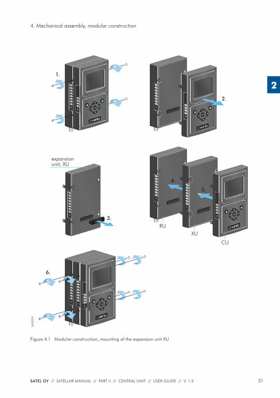
The expansion unit XU is attached between RU and CU as described in the Figure 4.1.
First remove the CU and RU from each other, see the fi gure. Take the rubber cover from the unit-to-unit connector of the XU. Modular constraction allows you to connect the expansion unit XU between RU and CU units. Align the tabs of the CU with the mounting holes of the XU and press the units together, and do the same between RU unit and XU+CU units. Finally, tighten the connections with the screws. Now the combination can be mounted either by DIN rail adapters or by a two-piece mounting clip.
21SATEL OY // SATELLAR MANUAL // PART II // CENTRAL UNIT // USER GUIDE // V. 1.2
4. Mechanical assembly, modular construction
2
Figure 4.1 Modular construction, mounting of the expansion unit XU
1.
TD
RD
PWR
STAT
RX
TX
CTS
RTS
USB
ETH
PWR
STAT
OK
TD
RD
PWR
STAT
RX
TX
CTS
RTS
USB
ETH
PWR
STAT
OK
2.
TD
RD
PWR
STAT
RX
TX
CTS
RTS
TD
RD
PWR
STAT
RX
TX
CTS
RTS
USB
ETH
PWR
STAT
OK
6.
TD
RD
PWR
STAT
RX
TX
CTS
RTS
RU
4.
TD
RD
PWR
STAT
RX
TX
CTS
RTS
XU
USB
ETH
PWR
STAT
OK
5.
CU
TD
RD
PWR
STAT
RX
TX
CTS
RTS
3.
expansionunit, XU
SA00
024
22 SATEL OY // SATELLAR MANUAL // PART II // CENTRAL UNIT // USER GUIDE // V. 1.2
5. Interfaces
2
5. Interfaces
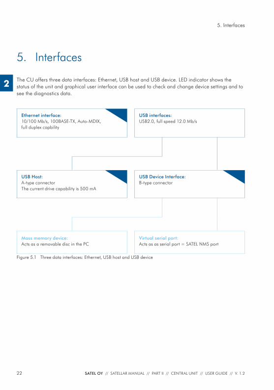
The CU offers three data interfaces: Ethernet, USB host and USB device. LED indicator shows the status of the unit and graphical user interface can be used to check and change device settings and to see the diagnostics data.
Ethernet interface:10/100 Mb/s, 100BASE-TX, Auto-MDIX, full duplex capbility
USB interfaces:USB2.0, full speed 12.0 Mb/s
USB Host:A-type connectorThe current drive capability is 500 mA
USB Device Interface:B-type connector
Mass memory device:Acts as a removable disc in the PC
Virtual serial port:Acts as as serial port = SATEL NMS port
Figure 5.1 Three data interfaces: Ethernet, USB host and USB device
23SATEL OY // SATELLAR MANUAL // PART II // CENTRAL UNIT // USER GUIDE // V. 1.2
5. Interfaces
2
The USB interfaces support USB2.0 Full Speed (12.0 Mb/s) data rates. Both USB host and device interfaces are available. For USB host the A type connector is used and for USB device the connector is B type. The current drive capability of the USB host interface is 500 mA. The USB device interface has two modes: Mass memory device and Virtual serial port. The mode can be selected in Modem Settings, General cat-egory and in addition by the function button as described in chapter 5.5.
In the Mass memory device -mode a PC can be connected to the USB device interface and SATELLAR acts as a Removable Disc in the PC. The removable disk contains copies of system log fi les, which can be copied to the PC. Update fi les can be copied to the removable disk and be
used in the Firmware Updater (see chapter 8.3). Any other fi les copied to the removable disk are removed when the cable is disconnected.
In Virtual serial port -mode, the USB port acts as a serial port. When the USB port is connected to a PC, the virtual serial port device is created in the PC. This virtual port appears to windows as a normal serial port: the only difference is that an actual D9 connector is not used. This allows programs to connect to serial ports in order to access the CU via the USB connection.
Windows PC requires a special driver, available from SATEL. The Virtual Serial port acts as a SATEL NMS port, allowing a program such as SATEL NMS PC to be used to change the settings of SATELLAR.
5.1 EthernetEthernet interface is 10/100 Mb/s 100BASE-TX with Auto-MDIX and full-duplex capability.
5.2 USB
TD
RD
PWR
STAT
RX
TX
CTS
RTS
USB
ETH
PWR
STAT
OK
SA00
008
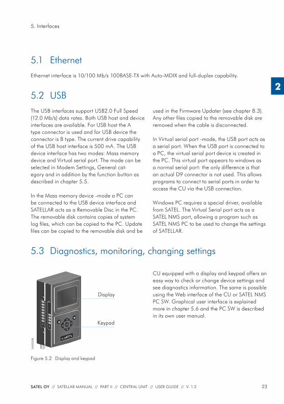
CU equipped with a display and keypad offers an easy way to check or change device settings and see diagnostics information. The same is possible using the Web interface of the CU or SATEL NMS PC SW. Graphical user interface is explained more in chapter 5.6 and the PC SW is described in its own user manual.
Display
Keypad
Figure 5.2 Display and keypad
5.3 Diagnostics, monitoring, changing settings
24 SATEL OY // SATELLAR MANUAL // PART II // CENTRAL UNIT // USER GUIDE // V. 1.2
5. Interfaces
2
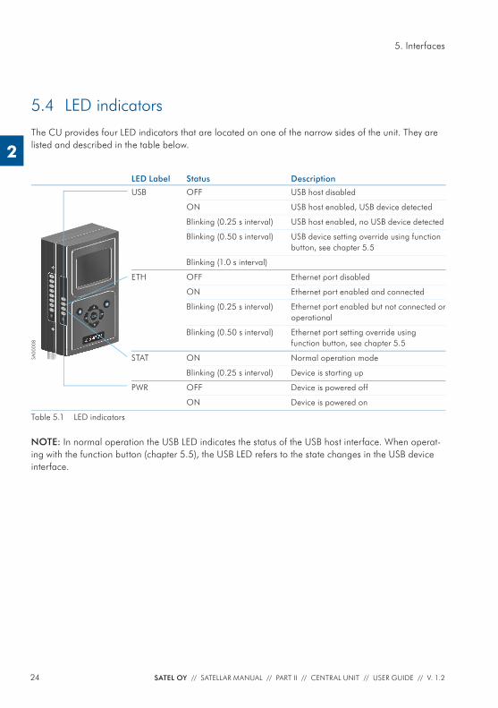
5.4 LED indicatorsThe CU provides four LED indicators that are located on one of the narrow sides of the unit. They are listed and described in the table below.
LED Label Status Description
TD
RD
PWR
STAT
RX
TX
CTS
RTS
USB
ETH
PWR
STAT
OK
SA00
008
USB OFF USB host disabled
ON USB host enabled, USB device detected
Blinking (0.25 s interval) USB host enabled, no USB device detected
Blinking (0.50 s interval) USB device setting override using function button, see chapter 5.5
Blinking (1.0 s interval)
ETH OFF Ethernet port disabled
ON Ethernet port enabled and connected
Blinking (0.25 s interval) Ethernet port enabled but not connected or operational
Blinking (0.50 s interval) Ethernet port setting override using function button, see chapter 5.5
STAT ON Normal operation mode
Blinking (0.25 s interval) Device is starting up
PWR OFF Device is powered off
ON Device is powered on
Table 5.1 LED indicators
NOTE: In normal operation the USB LED indicates the status of the USB host interface. When operat-ing with the function button (chapter 5.5), the USB LED refers to the state changes in the USB device interface.
25SATEL OY // SATELLAR MANUAL // PART II // CENTRAL UNIT // USER GUIDE // V. 1.2
5. Interfaces
2
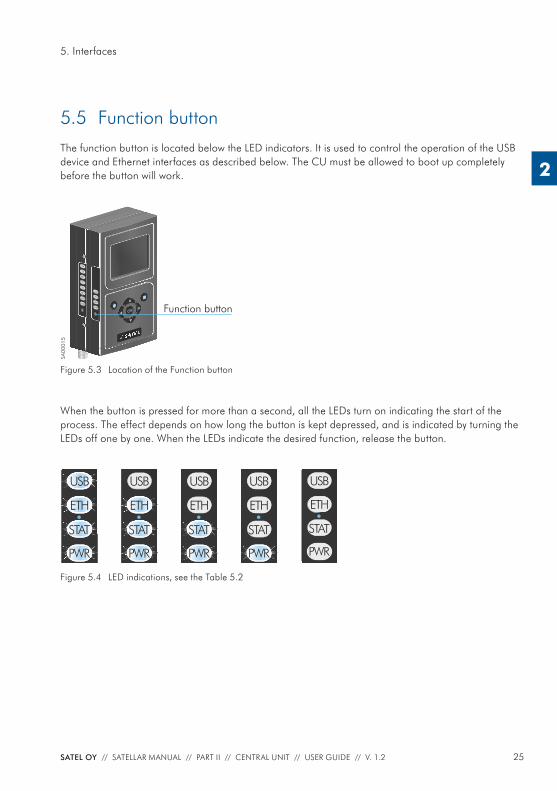
5.5 Function buttonThe function button is located below the LED indicators. It is used to control the operation of the USB device and Ethernet interfaces as described below. The CU must be allowed to boot up completely before the button will work.
When the button is pressed for more than a second, all the LEDs turn on indicating the start of the process. The effect depends on how long the button is kept depressed, and is indicated by turning the LEDs off one by one. When the LEDs indicate the desired function, release the button.
TD
RD
PWR
STAT
RX
TX
CTS
RTS
USB
ETH
PWR
STAT
OK Function button
SA00
015
Figure 5.3 Location of the Function button
Figure 5.4 LED indications, see the Table 5.2
PWR
STAT
ETH
USB
PWR
STAT
ETH
USB
STAT
ETH
USB
PWR PWR
STAT
USB
ETH
PWR
STAT
ETH
USB
26 SATEL OY // SATELLAR MANUAL // PART II // CENTRAL UNIT // USER GUIDE // V. 1.2
5. Interfaces
2
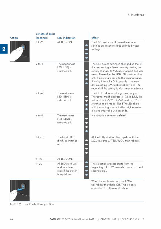
Length of pressAction [seconds] LED indication Effect
1 to 2 All LEDs ON.
••••
The USB device and Ethernet interface settings are reset to states defi ned by user settings.
2 to 4 The uppermost LED (USB) is switched off. •
•••
The USB device setting is changed so that if the user setting is Mass memory device, the setting changes to Virtual serial port and vice versa. Thereafter the USB LED starts to blink until the setting is reset to the original value. Blinking interval is 0.5 seconds if the new device setting is Virtual serial port and 1.0 seconds if the setting is Mass memory device.
4 to 6 The next lower LED (ETH) is switched off.
••••
The CU IP address settings are changed. Thereafter the IP address is 192.168.1.1, the net mask is 255.255.255.0, and DHCP is switched to off mode. The ETH LED blinks until the setting is reset to the original value. Blinking interval is 0.5 seconds.
6 to 8 The next lower LED (STAT) is switched off.
••••
No specifi c operation defi ned.
8 to 10 The fourth LED (PWR) is switched off.
••••
All the LEDs start to blink rapidly until the MCU restarts. SATELLAR CU then reboots.
> 10 All LEDs ON.
••••
> 20 All LEDs turn ON and remain on even if the button is kept down.
The selection process starts from the beginning (11 to 12 seconds counts as 1 to 2 seconds etc.).
When button is released, the FPGA will reboot the whole CU. This is nearly equivalent to a Power-off reboot.
Table 5.2 Function button operation
27SATEL OY // SATELLAR MANUAL // PART II // CENTRAL UNIT // USER GUIDE // V. 1.2
5. Interfaces
2
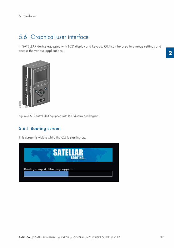
5.6 Graphical user interfaceIn SATELLAR device equipped with LCD display and keypad, GUI can be used to change settings and access the various applications.
Figure 5.5 Central Unit equipped with LCD display and keypad
5.6.1 Booting screen
This screen is visible while the CU is starting up.
TD
RD
PWR
STAT
RX
TX
CTS
RTS
USB
ETH
PWR
STAT
OK
SA00
008
28 SATEL OY // SATELLAR MANUAL // PART II // CENTRAL UNIT // USER GUIDE // V. 1.2
5. Interfaces
2
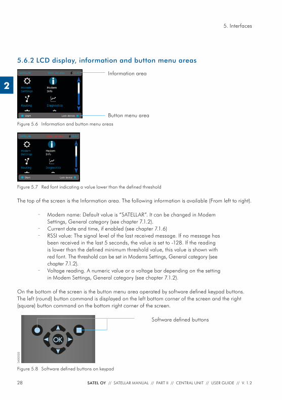
5.6.2 LCD display, information and button menu areas
Figure 5.6 Information and button menu areas
Figure 5.7 Red font indicating a value lower than the defi ned threshold
The top of the screen is the Information area. The following information is available (From left to right).
– Modem name: Default value is “SATELLAR”. It can be changed in Modem Settings, General category (see chapter 7.1.2).
– Current date and time, if enabled (see chapter 7.1.6) – RSSI value: The signal level of the last received message. If no message has
been received in the last 5 seconds, the value is set to -128. If the reading is lower than the defi ned minimum threshold value, this value is shown with red font. The threshold can be set in Modems Settings, General category (see chapter 7.1.2).
– Voltage reading. A numeric value or a voltage bar depending on the setting in Modem Settings, General category (see chapter 7.1.2).
On the bottom of the screen is the button menu area operated by software defi ned keypad buttons. The left (round) button command is displayed on the left bottom corner of the screen and the right (square) button command on the bottom right corner of the screen.
OK
SA00
003
Figure 5.8 Software defi ned buttons on keypad
Software defi ned buttons
Information area
Button menu area
29SATEL OY // SATELLAR MANUAL // PART II // CENTRAL UNIT // USER GUIDE // V. 1.2
5. Interfaces
2
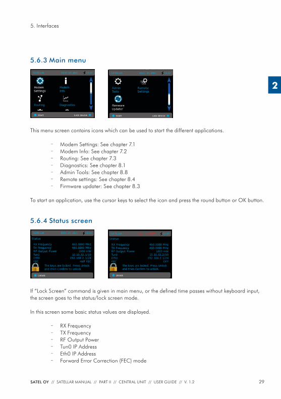
5.6.3 Main menu
This menu screen contains icons which can be used to start the different applications.
– Modem Settings: See chapter 7.1 – Modem Info: See chapter 7.2 – Routing: See chapter 7.3 – Diagnostics: See chapter 8.1 – Admin Tools: See chapter 8.8 – Remote settings: See chapter 8.4 – Firmware updater: See chapter 8.3
To start an application, use the cursor keys to select the icon and press the round button or OK button.
5.6.4 Status screen
If “Lock Screen” command is given in main menu, or the defi ned time passes without keyboard input, the screen goes to the status/lock screen mode.
In this screen some basic status values are displayed.
– RX Frequency – TX Frequency – RF Output Power – Tun0 IP Address – Eth0 IP Address – Forward Error Correction (FEC) mode
30 SATEL OY // SATELLAR MANUAL // PART II // CENTRAL UNIT // USER GUIDE // V. 1.2
5. Interfaces
2
No input is allowed in this screen, except to unlock the screen. To do this, follow the instruction on screen. If PIN code has been enabled, the correct code must be entered to unlock.
5.6.5 Screen save mode
After a timeout set in Modem Settings, General category (see chapter 7.1.2), the display is turned off. When any button is pressed, the Status screen is displayed and the UI can be unlocked as normal.
5.7 WWW User interfaceThis interface can be used with a web browser application, such as Mozilla Firefox. The url to access the WWW -page is http://<modem’s IP address>. By default this is http://192.168.1.1. If the current IP address is unknown, it can be forced to 192.168.1.1 by using the function button as explained in chap-ter 5.5, or using the Graphical user interface, if present. The WWW interface can also be used across the radio link, once routes have been set (see chapter 6). In this case either of the IP addresses defi ned can be used (both the eth0 and tun0 addresses work).
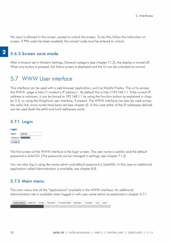
5.7.1 Login
The fi rst screen of the WWW interface is the login screen. The user name is satellar and the default password is Satel123. (The password can be changed in settings, see chapter 7.1.2)
You can also log in using the name admin and default password is Satel456. In this case an additional application called Administration is available, see chapter 8.8.
5.7.2 Main menu
The main menu lists all the “applications” available in the WWW interface. An additional Administration tab is available when logged in with user name admin as explained in chapter 5.7.1.
31SATEL OY // SATELLAR MANUAL // PART II // CENTRAL UNIT // USER GUIDE // V. 1.2
5. Interfaces
2
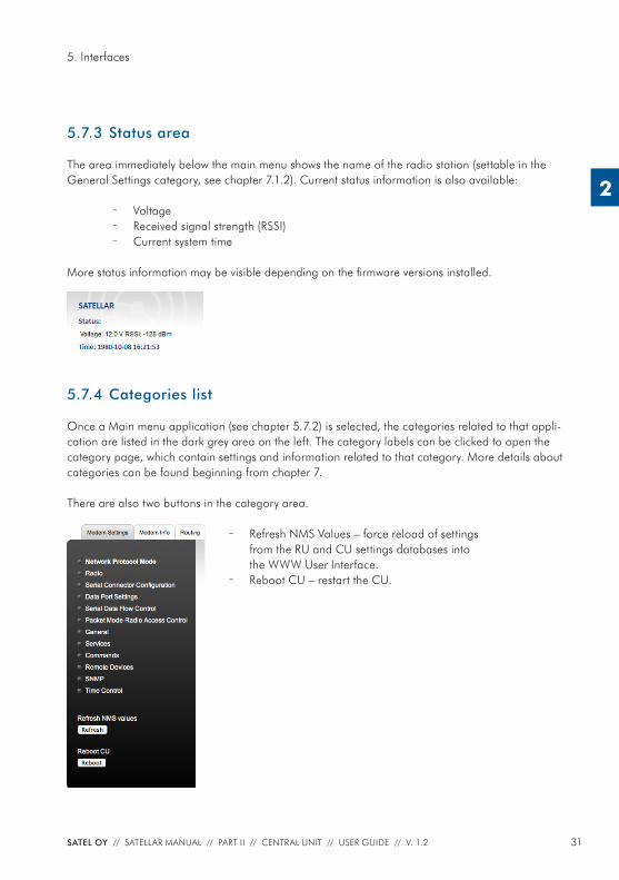
5.7.3 Status area
The area immediately below the main menu shows the name of the radio station (settable in the General Settings category, see chapter 7.1.2). Current status information is also available:
– Voltage – Received signal strength (RSSI) – Current system time
More status information may be visible depending on the fi rmware versions installed.
5.7.4 Categories list
Once a Main menu application (see chapter 5.7.2) is selected, the categories related to that appli-cation are listed in the dark grey area on the left. The category labels can be clicked to open the category page, which contain settings and information related to that category. More details about categories can be found beginning from chapter 7. There are also two buttons in the category area.
– Refresh NMS Values – force reload of settings from the RU and CU settings databases into the WWW User Interface.
– Reboot CU – restart the CU.
32 SATEL OY // SATELLAR MANUAL // PART II // CENTRAL UNIT // USER GUIDE // V. 1.2
5. Interfaces
2
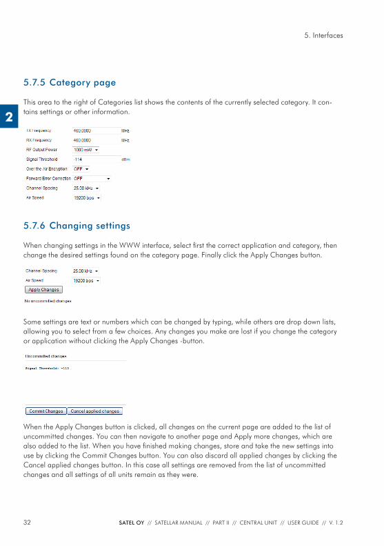
5.7.5 Category page
This area to the right of Categories list shows the contents of the currently selected category. It con-tains settings or other information.
5.7.6 Changing settings
When changing settings in the WWW interface, select fi rst the correct application and category, then change the desired settings found on the category page. Finally click the Apply Changes button.
Some settings are text or numbers which can be changed by typing, while others are drop down lists, allowing you to select from a few choices. Any changes you make are lost if you change the category or application without clicking the Apply Changes -button.
When the Apply Changes button is clicked, all changes on the current page are added to the list of uncommitted changes. You can then navigate to another page and Apply more changes, which are also added to the list. When you have fi nished making changes, store and take the new settings into use by clicking the Commit Changes button. You can also discard all applied changes by clicking the Cancel applied changes button. In this case all settings are removed from the list of uncommitted changes and all settings of all units remain as they were.
33SATEL OY // SATELLAR MANUAL // PART II // CENTRAL UNIT // USER GUIDE // V. 1.2
5. Interfaces
2
When Commit Changes is clicked, the CU will store settings into the settings database and the Radio Unit, and restart all necessary Linux processes. Therefore the committing process may take a relatively long time, sometimes up to a minute.
NOTE: If the IP Address has been changed, the browser will be automatically redirected to the new address, but in case the network address part of the IP address has changed, you’ll need to modify your computer’s IP settings so that it is again in the same LAN as the modem to be able to continue using the WWW interface.
5.8 SATEL NMSSATEL NMS is a Network Management System. Devices that support SATEL NMS can be confi gured and monitored using external software provided by SATEL. One such program is SATEL NMS PC. Confi guration and monitoring can be performed either locally using a cable, or remotely via a radio link. The SATELLAR Central Unit supports SATEL NMS, and provides the following features.Connection options:
– Connect via TCP/IP Port 55555 – Connect via USB Device port when the USB port is in Virtual Serial port
mode. (See chapters 5.2 and 7.1.2 for details) – Remote connection via radio network is available when the routing settings
are correctly defi ned.
Most settings available via the User Interfaces of the CU are also accessible using SATEL NMS. For this purpose, the NMSID (Network Management System IDentifi er) as well as Sub-Unit number of each setting is listed in this manual. The NMSIDs are also used by the NMS Import application (see chapter 8.5). Note that the NMS Address of the CU is the same as the RMAC Address of the attached Radio Unit. See the Radio Unit user manual for details.
5.9 SSHSATELLAR’s linux command line can be accessed using the SSH protocol. To do this you need a SSH client, such as putty.exe. The user name is satellar and the password is Satel123.
34 SATEL OY // SATELLAR MANUAL // PART II // CENTRAL UNIT // USER GUIDE // V. 1.2
6. Data transmission
2
6. Data transmission
The CU is used to transfer data over the IP protocol. Multiple IP protocols are supported, such as TCP/IP, UDP and ICMP. A prerequisite for wireless IP transmission is that the RU is confi gured to packet routing protocol mode as explained in the RU user manual.
6.1 Internet protocolEach CU has an IP address belonging to the Local Area Network (LAN) to which they are connected via their Ethernet interface. Each CU also has another IP address belonging to a second LAN, the SATELLAR RU LAN. This LAN is formed by the radio protocol. These two interfaces are called eth0 and tun0 according to standard Linux naming conventions. The CU acts as an IP router device, routing IP packets between its Ethernet interface (eth0) and the radio network provided by SATELLAR RUs (tun0).
6.1.1 Example
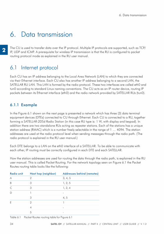
In the Figure 6.1 shown on the next page is presented a network which has three (3) data terminal equipment devices (DTEs) connected to CU through Ethernet. Each CU is connected to a RU, together forming a SATELLAR-2DSd Radio Station (in this case RU type is: 1 W, with display and keypad). In addition there are two standalone RUs acting as repeater stations. Each of the stations has a unique station address (RMAC) which is a number freely selectable in the range of 1 … 4094. The station addresses are used at the radio protocol level when sending messages through the radio path. (The radio protocol is explained in the RU user manual.)
Each DTE belongs to a LAN on the eth0 interface of a SATELLAR. To be able to communicate with each other, IP routing must be correctly confi gured in each DTE and each SATELLAR.
How the station addresses are used for routing the data through the radio path, is explained in the RU user manual. This is called Packet Routing. For the network topology seen on Figure 6.1 the Packet Routes routing table looks like the following:
Radio unit Next hop (neighbor) Addresses behind (remotes)
A 2 3, 4, 5
B 3 1, 2, 5
C 3 1, 2, 4
D 1 -
3 4, 5
E 2 1
4 -
5 -
Table 6.1 Packet Routes routing table for Figure 6.1
35SATEL OY // SATELLAR MANUAL // PART II // CENTRAL UNIT // USER GUIDE // V. 1.2
6. Data transmission
2
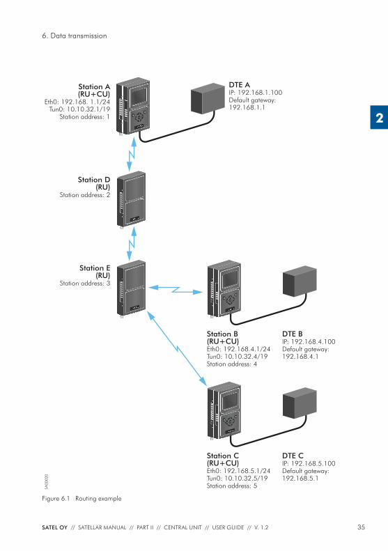
Figure 6.1 Routing example
TD
RD
PWR
STAT
RU-145000
RX
TX
CTS
RTS
Station D(RU)
Station address: 2
SA00
020
Station E(RU)
Station address: 3TD
RD
PWR
STAT
RU-145000
RX
TX
CTS
RTS
TD
RD
PWR
STAT
RU-145000
RX
TX
CTS
RTS
USB
ETH
PWR
STAT
CU-1U2100
OK
Station B(RU+CU)Eth0: 192.168.4.1/24Tun0: 10.10.32.4/19Station address: 4
DTE BIP: 192.168.4.100Default gateway: 192.168.4.1
Station C(RU+CU)Eth0: 192.168.5.1/24Tun0: 10.10.32.5/19Station address: 5
DTE CIP: 192.168.5.100Default gateway: 192.168.5.1
TD
RD
PWR
STAT
RU-145000
RX
TX
CTS
RTS
USB
ETH
PWR
STAT
CU-1U2100
OK
Station A(RU+CU)
Eth0: 192.168. 1.1/24Tun0: 10.10.32.1/19
Station address: 1
DTE AIP: 192.168.1.100Default gateway: 192.168.1.1TD
RD
PWR
STAT
RU-145000
RX
TX
CTS
RTS
USB
ETH
PWR
STAT
CU-1U2100
OK
36 SATEL OY // SATELLAR MANUAL // PART II // CENTRAL UNIT // USER GUIDE // V. 1.2
6. Data transmission
2
6.1.2 Forming the tun0 IP address
Whenever the station address (RMAC) of a SATELLAR is changed, the IP address for the tun0 interface is automatically determined: If the station address is X, the tun0 IP address is set to 10.10.32.X, net-mask 19.
In case the station address (X) is larger than 254, the tun0 address is of the form 10.10.A.B, where A = 32 + (X / 254), rounded down and B = 1 + (X % 254) [% being the modulus operator]. For exam-ple, RMAC 500 translates to tun0 address 10.10.33.247.
In case a subnet with network address 10.10.32.0/19 is already in use in a system, a SATELLAR radio network can be confi gured to use another tun0 network Base Address. To do this, use the Admin Settings application (see chapter 8.8.2). All modems MUST use the same tun0 Base Address.
6.1.3 Choosing the eth0 IP address
Eth0 IP addresses must be selected according to two rules.
– Each CU’s eth0 interface must belong to a different subnet. – The CU and the corresponding DTE must belong to the same subnet.
Additionally
– It is a good practice to set the CU IP address as 192.168.X.1 where X is the station address (RMAC), if possible.
– The default gateway for the DTE should be the corresponding CU, unless there is another gateway present in the LAN. In this case the routing tables of the gateway must be modifi ed accordingly.
The rules can be clarifi ed with the help of Figure 6.1: Routing example.
The station A has
– Station address (RMAC) 1 à tun0 address is 10.10.32.1 – Eth0 address 192.168.1.1/24 (i.e. subnet mask is 255.255.255.0) – Therefore DTE A must have an address 192.168.1.X, e.g. 192.168.1.100 and
its default gateway must be 192.168.1.1
37SATEL OY // SATELLAR MANUAL // PART II // CENTRAL UNIT // USER GUIDE // V. 1.2
6. Data transmission
2
The station B has
– Station address (RMAC) 4 à tun0 address is 10.10.32.4 – Eth0 address must be chosen so that it belongs to a subnet different from
station A, e.g. 192.168.4.1/24 – Therefore DTE B must have an address 192.168.4.X, e.g. 192.168.4.100 and
its default gateway must be 192.168.4.1
The station C has
– Station address (RMAC) 5 à tun0 address is 10.10.32.5 – Eth0 address must be chosen so that it belongs to a subnet different from
stations A and B, e.g. 192.168.5.1/24 – Therefore DTE C must have an address 192.168.5.X, e.g. 192.168.5.100 and
its default gateway must be 192.168.5.1
Stations D and E act only as repeaters without a CU and therefore no local Ethernet connection. So they have no IP addresses – just station addresses.
6.1.4 Setting IP routes
After all the addresses have been set it is still required to defi ne IP routes for each of the CU. Routing data must include the address and net mask of each of the destination subnets (LANs) that need to be reached and the gateway it can be reached through. The gateway address is the tun0 address of the target CU.
For the network in the Figure 6.1 the IP routing tables of each CU equipped station are:
Station Destination/net mask Gateway
A 192.168.4.0/24 10.10.32.4
192.168.5.0/24 10.10.32.5
B 192.168.1.0/24 10.10.32.1
192.168.5.0/24 10.10.32.5
C 192.168.1.0/24 10.10.32.1
192.168.4.0/24 10.10.32.4
Table 6.2 IP routing tables for each CU in Figure 6.1
38 SATEL OY // SATELLAR MANUAL // PART II // CENTRAL UNIT // USER GUIDE // V. 1.2
6. Data transmission
2
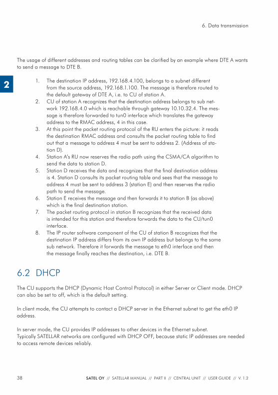
The usage of different addresses and routing tables can be clarifi ed by an example where DTE A wants to send a message to DTE B.
1. The destination IP address, 192.168.4.100, belongs to a subnet different from the source address, 192.168.1.100. The message is therefore routed to the default gateway of DTE A, i.e. to CU of station A.
2. CU of station A recognizes that the destination address belongs to sub net-work 192.168.4.0 which is reachable through gateway 10.10.32.4. The mes-sage is therefore forwarded to tun0 interface which translates the gateway address to the RMAC address, 4 in this case.
3. At this point the packet routing protocol of the RU enters the picture: it reads the destination RMAC address and consults the packet routing table to fi nd out that a message to address 4 must be sent to address 2. (Address of sta-tion D).
4. Station A’s RU now reserves the radio path using the CSMA/CA algorithm to send the data to station D.
5. Station D receives the data and recognizes that the fi nal destination address is 4. Station D consults its packet routing table and sees that the message to address 4 must be sent to address 3 (station E) and then reserves the radio path to send the message.
6. Station E receives the message and then forwards it to station B (as above) which is the fi nal destination station.
7. The packet routing protocol in station B recognizes that the received data is intended for this station and therefore forwards the data to the CU/tun0 interface.
8. The IP router software component of the CU of station B recognizes that the destination IP address differs from its own IP address but belongs to the same sub network. Therefore it forwards the message to eth0 interface and then the message fi nally reaches the destination, i.e. DTE B.
6.2 DHCPThe CU supports the DHCP (Dynamic Host Control Protocol) in either Server or Client mode. DHCP can also be set to off, which is the default setting.
In client mode, the CU attempts to contact a DHCP server in the Ethernet subnet to get the eth0 IP address.
In server mode, the CU provides IP addresses to other devices in the Ethernet subnet.Typically SATELLAR networks are confi gured with DHCP OFF, because static IP addresses are needed to access remote devices reliably.
39SATEL OY // SATELLAR MANUAL // PART II // CENTRAL UNIT // USER GUIDE // V. 1.2
7. Settings
2
7. Settings
The CU has several settings, which affect the operation of the IP routing and other things. The CU can also be used to change the settings of the RU as well as any other units present. There are several interfaces to use when viewing info and changing settings (see chapter 5.6)
The settings are grouped into categories used in the LCD and WWW GUIs. Each setting isalso listed with the sub-unit number and NMSID for use with NMS Protocol and NMS Importfeatures. See chapter 5.8 for information about NMSIDs and chapter 8.5 for information about NMS Import.
NOTE: See the settings selection quide at the end of the manual.
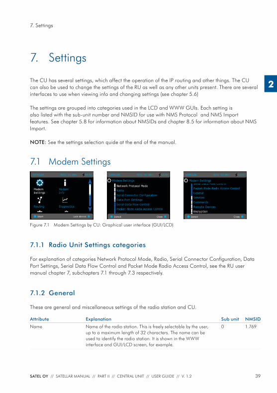
7.1 Modem Settings
Figure 7.1 Modem Settings by CU: Graphical user interface (GUI/LCD)
7.1.1 Radio Unit Settings categories
For explanation of categories Network Protocol Mode, Radio, Serial Connector Confi guration, Data Port Settings, Serial Data Flow Control and Packet Mode Radio Access Control, see the RU user manual chapter 7, subchapters 7.1 through 7.3 respectively.
7.1.2 General
These are general and miscellaneous settings of the radio station and CU.
Attribute Explanation Sub unit NMSID
Name Name of the radio station. This is freely selectable by the user, up to a maximum length of 32 characters. The name can be used to identify the radio station. It is shown in the WWW interface and GUI/LCD screen, for example.
0 1.769
40 SATEL OY // SATELLAR MANUAL // PART II // CENTRAL UNIT // USER GUIDE // V. 1.2
7. Settings
2
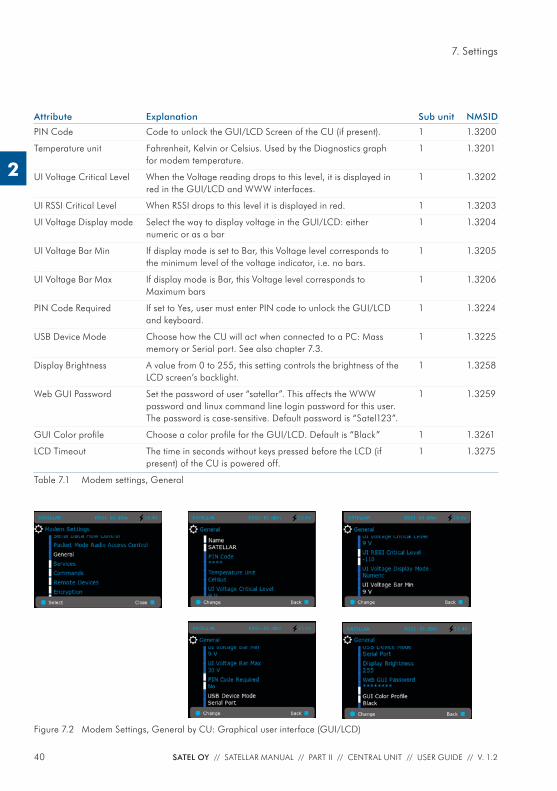
Attribute Explanation Sub unit NMSID
PIN Code Code to unlock the GUI/LCD Screen of the CU (if present). 1 1.3200
Temperature unit Fahrenheit, Kelvin or Celsius. Used by the Diagnostics graph for modem temperature.
1 1.3201
UI Voltage Critical Level When the Voltage reading drops to this level, it is displayed in red in the GUI/LCD and WWW interfaces.
1 1.3202
UI RSSI Critical Level When RSSI drops to this level it is displayed in red. 1 1.3203
UI Voltage Display mode Select the way to display voltage in the GUI/LCD: either numeric or as a bar
1 1.3204
UI Voltage Bar Min If display mode is set to Bar, this Voltage level corresponds to the minimum level of the voltage indicator, i.e. no bars.
1 1.3205
UI Voltage Bar Max If display mode is Bar, this Voltage level corresponds to Maximum bars
1 1.3206
PIN Code Required If set to Yes, user must enter PIN code to unlock the GUI/LCD and keyboard.
1 1.3224
USB Device Mode Choose how the CU will act when connected to a PC: Mass memory or Serial port. See also chapter 7.3.
1 1.3225
Display Brightness A value from 0 to 255, this setting controls the brightness of the LCD screen’s backlight.
1 1.3258
Web GUI Password Set the password of user “satellar”. This affects the WWW password and linux command line login password for this user. The password is case-sensitive. Default password is “Satel123”.
1 1.3259
GUI Color profi le Choose a color profi le for the GUI/LCD. Default is “Black” 1 1.3261
LCD Timeout The time in seconds without keys pressed before the LCD (if present) of the CU is powered off.
1 1.3275
Table 7.1 Modem settings, General
Figure 7.2 Modem Settings, General by CU: Graphical user interface (GUI/LCD)
41SATEL OY // SATELLAR MANUAL // PART II // CENTRAL UNIT // USER GUIDE // V. 1.2
7. Settings
2
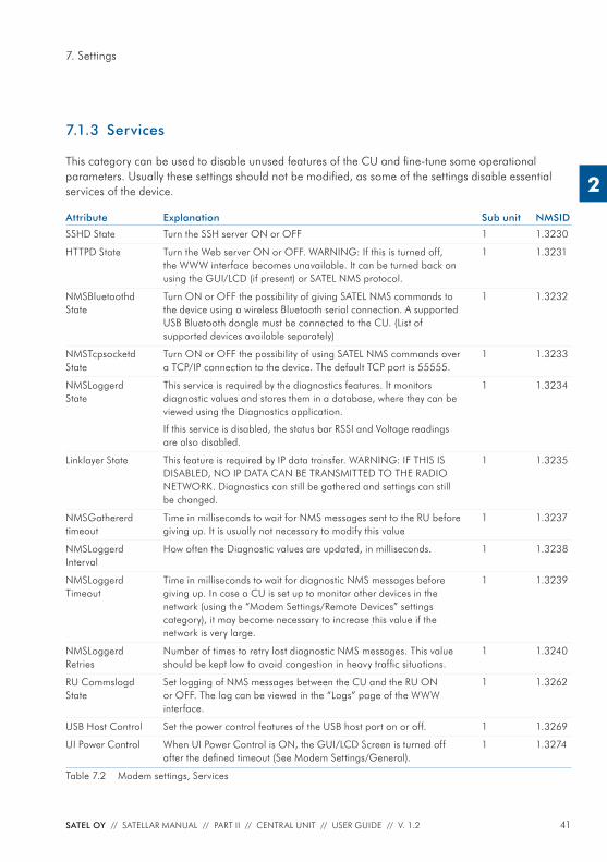
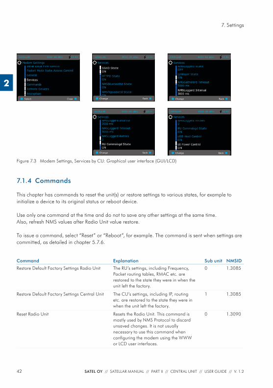
7.1.3 Services
This category can be used to disable unused features of the CU and fi ne-tune some operational parameters. Usually these settings should not be modifi ed, as some of the settings disable essential services of the device.
Attribute Explanation Sub unit NMSID
SSHD State Turn the SSH server ON or OFF 1 1.3230
HTTPD State Turn the Web server ON or OFF. WARNING: If this is turned off, the WWW interface becomes unavailable. It can be turned back on using the GUI/LCD (if present) or SATEL NMS protocol.
1 1.3231
NMSBluetoothd State
Turn ON or OFF the possibility of giving SATEL NMS commands to the device using a wireless Bluetooth serial connection. A supported USB Bluetooth dongle must be connected to the CU. (List of supported devices available separately)
1 1.3232
NMSTcpsocketd State
Turn ON or OFF the possibility of using SATEL NMS commands over a TCP/IP connection to the device. The default TCP port is 55555.
1 1.3233
NMSLoggerd State
This service is required by the diagnostics features. It monitors diagnostic values and stores them in a database, where they can be viewed using the Diagnostics application.
If this service is disabled, the status bar RSSI and Voltage readings are also disabled.
1 1.3234
Linklayer State This feature is required by IP data transfer. WARNING: IF THIS IS DISABLED, NO IP DATA CAN BE TRANSMITTED TO THE RADIO NETWORK. Diagnostics can still be gathered and settings can still be changed.
1 1.3235
NMSGathererd timeout
Time in milliseconds to wait for NMS messages sent to the RU before giving up. It is usually not necessary to modify this value
1 1.3237
NMSLoggerd Interval
How often the Diagnostic values are updated, in milliseconds. 1 1.3238
NMSLoggerd Timeout
Time in milliseconds to wait for diagnostic NMS messages before giving up. In case a CU is set up to monitor other devices in the network (using the “Modem Settings/Remote Devices” settings category), it may become necessary to increase this value if the network is very large.
1 1.3239
NMSLoggerd Retries
Number of times to retry lost diagnostic NMS messages. This value should be kept low to avoid congestion in heavy traffi c situations.
1 1.3240
RU Commslogd State
Set logging of NMS messages between the CU and the RU ON or OFF. The log can be viewed in the “Logs” page of the WWW interface.
1 1.3262
USB Host Control Set the power control features of the USB host port on or off. 1 1.3269
UI Power Control When UI Power Control is ON, the GUI/LCD Screen is turned off after the defi ned timeout (See Modem Settings/General).
1 1.3274
Table 7.2 Modem settings, Services
42 SATEL OY // SATELLAR MANUAL // PART II // CENTRAL UNIT // USER GUIDE // V. 1.2
7. Settings
2
Figure 7.3 Modem Settings, Services by CU: Graphical user interface (GUI/LCD)
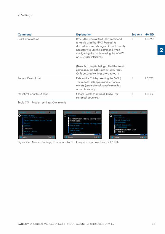
7.1.4 Commands
This chapter has commands to reset the unit(s) or restore settings to various states, for example to initialize a device to its original status or reboot device.
Use only one command at the time and do not to save any other settings at the same time.Also, refresh NMS values after Radio Unit value restore.
To issue a command, select “Reset” or “Reboot”, for example. The command is sent when settings are committed, as detailed in chapter 5.7.6.
Command Explanation Sub unit NMSID
Restore Default Factory Settings Radio Unit The RU’s settings, including Frequency, Packet routing tables, RMAC etc. are restored to the state they were in when the unit left the factory.
0 1.3085
Restore Default Factory Settings Central Unit The CU’s settings, including IP, routing etc. are restored to the state they were in when the unit left the factory.
1 1.3085
Reset Radio Unit Resets the Radio Unit. This command is mostly used by NMS Protocol to discard unsaved changes. It is not usually necessary to use this command when confi guring the modem using the WWW or LCD user interfaces.
0 1.3090
43SATEL OY // SATELLAR MANUAL // PART II // CENTRAL UNIT // USER GUIDE // V. 1.2
7. Settings
2
Command Explanation Sub unit NMSID
Reset Central Unit Resets the Central Unit. This command is mostly used by NMS Protocol to discard unsaved changes. It is not usually necessary to use this command when confi guring the modem using the WWW or LCD user interfaces.
(Note that despite being called the Reset command, the CU is not actually reset. Only unsaved settings are cleared. )
1 1.3090
Reboot Central Unit Reboot the CU (by resetting the MCU). The reboot lasts approximately one a minute (see technical specifi cation for accurate values)
1 1.3093
Statistical Counters Clear Clears (resets to zero) all Radio Unit statistical counters.
1 1.3109
Table 7.3 Modem settings, Commands
Figure 7.4 Modem Settings, Commands by CU: Graphical user interface (GUI/LCD)
44 SATEL OY // SATELLAR MANUAL // PART II // CENTRAL UNIT // USER GUIDE // V. 1.2
7. Settings
2
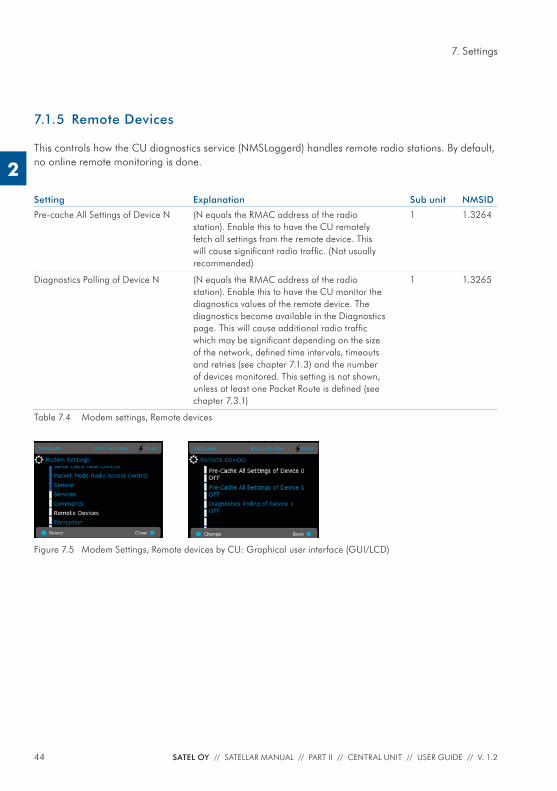
7.1.5 Remote Devices
This controls how the CU diagnostics service (NMSLoggerd) handles remote radio stations. By default, no online remote monitoring is done.
Setting Explanation Sub unit NMSID
Pre-cache All Settings of Device N (N equals the RMAC address of the radio station). Enable this to have the CU remotely fetch all settings from the remote device. This will cause signifi cant radio traffi c. (Not usually recommended)
1 1.3264
Diagnostics Polling of Device N (N equals the RMAC address of the radio station). Enable this to have the CU monitor the diagnostics values of the remote device. The diagnostics become available in the Diagnostics page. This will cause additional radio traffi c which may be signifi cant depending on the size of the network, defi ned time intervals, timeouts and retries (see chapter 7.1.3) and the number of devices monitored. This setting is not shown, unless at least one Packet Route is defi ned (see chapter 7.3.1)
1 1.3265
Table 7.4 Modem settings, Remote devices
Figure 7.5 Modem Settings, Remote devices by CU: Graphical user interface (GUI/LCD)
45SATEL OY // SATELLAR MANUAL // PART II // CENTRAL UNIT // USER GUIDE // V. 1.2
7. Settings
2
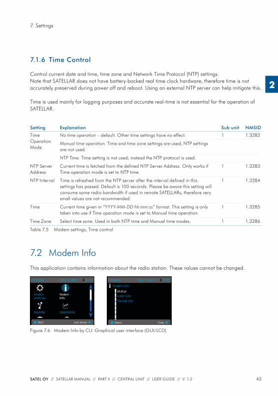
7.1.6 Time Control
Control current date and time, time zone and Network Time Protocol (NTP) settings.Note that SATELLAR does not have battery-backed real time clock hardware, therefore time is not accurately preserved during power off and reboot. Using an external NTP server can help mitigate this.
Time is used mainly for logging purposes and accurate real-time is not essential for the operation of SATELLAR.
Setting Explanation Sub unit NMSID
Time OperationMode
No time operation – default. Other time settings have no effect. 1 1.3282
Manual time operation. Time and time zone settings are used, NTP settings are not used.
NTP Time. Time setting is not used; instead the NTP protocol is used.
NTP Server Address
Current time is fetched from the defi ned NTP Server Address. Only works if Time operation mode is set to NTP time.
1 1.3283
NTP Interval Time is refreshed from the NTP server after the interval defi ned in this settings has passed. Default is 100 seconds. Please be aware this setting will consume some radio bandwidth if used in remote SATELLARs, therefore very small values are not recommended.
1 1.3284
Time Current time given in “YYYY-MM-DD hh:mm:ss” format. This setting is only taken into use if Time operation mode is set to Manual time operation.
1 1.3285
Time Zone Select time zone. Used in both NTP time and Manual time modes. 1 1.3286
Table 7.5 Modem settings, Time control
7.2 Modem InfoThis application contains information about the radio station. These values cannot be changed.
Figure 7.6 Modem Info by CU: Graphical user interface (GUI/LCD)
46 SATEL OY // SATELLAR MANUAL // PART II // CENTRAL UNIT // USER GUIDE // V. 1.2
7. Settings
2
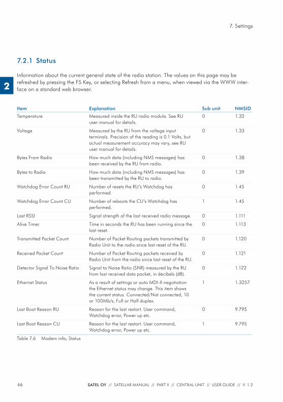
7.2.1 Status
Information about the current general state of the radio station. The values on this page may be refreshed by pressing the F5 Key, or selecting Refresh from a menu, when viewed via the WWW inter-face on a standard web browser.
Item Explanation Sub unit NMSID
Temperature Measured inside the RU radio module. See RU user manual for details.
0 1.32
Voltage Measured by the RU from the voltage input terminals. Precision of the reading is 0.1 Volts, but actual measurement accuracy may vary, see RU user manual for details.
0 1.33
Bytes From Radio How much data (including NMS messages) has been received by the RU from radio.
0 1.38
Bytes to Radio How much data (including NMS messages) has been transmitted by the RU to radio.
0 1.39
Watchdog Error Count RU Number of resets the RU’s Watchdog has performed.
0 1.45
Watchdog Error Count CU Number of reboots the CU’s Watchdog has performed.
1 1.45
Last RSSI Signal strength of the last received radio message. 0 1.111
Alive Timer Time in seconds the RU has been running since the last reset.
0 1.113
Transmitted Packet Count Number of Packet Routing packets transmitted by Radio Unit to the radio since last reset of the RU.
0 1.120
Received Packet Count Number of Packet Routing packets received by Radio Unit from the radio since last reset of the RU.
0 1.121
Detector Signal To Noise Ratio Signal to Noise Ratio (SNR) measured by the RU from last received data packet, in decibels (dB).
0 1.122
Ethernet Status As a result of settings or auto MDI-X negotiation the Ethernet status may change. This item shows the current status. Connected/Not connected, 10 or 100Mb/s, Full or Half duplex.
1 1.3257
Last Boot Reason RU Reason for the last restart. User command, Watchdog error, Power up etc.
0 9.795
Last Boot Reason CU Reason for the last restart. User command, Watchdog error, Power up etc.
1 9.795
Table 7.6 Modem info, Status
47SATEL OY // SATELLAR MANUAL // PART II // CENTRAL UNIT // USER GUIDE // V. 1.2
7. Settings
2
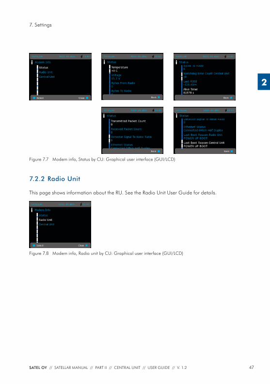
Figure 7.7 Modem info, Status by CU: Graphical user interface (GUI/LCD)
7.2.2 Radio Unit
This page shows information about the RU. See the Radio Unit User Guide for details.
Figure 7.8 Modem info, Radio unit by CU: Graphical user interface (GUI/LCD)
48 SATEL OY // SATELLAR MANUAL // PART II // CENTRAL UNIT // USER GUIDE // V. 1.2
7. Settings
2
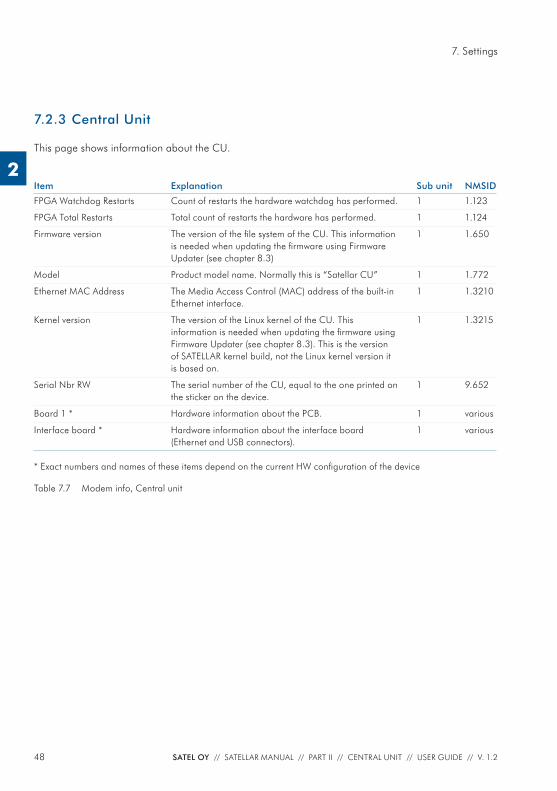
7.2.3 Central Unit
This page shows information about the CU.
Item Explanation Sub unit NMSID
FPGA Watchdog Restarts Count of restarts the hardware watchdog has performed. 1 1.123
FPGA Total Restarts Total count of restarts the hardware has performed. 1 1.124
Firmware version The version of the fi le system of the CU. This information is needed when updating the fi rmware using Firmware Updater (see chapter 8.3)
1 1.650
Model Product model name. Normally this is “Satellar CU” 1 1.772
Ethernet MAC Address The Media Access Control (MAC) address of the built-in Ethernet interface.
1 1.3210
Kernel version The version of the Linux kernel of the CU. This information is needed when updating the fi rmware using Firmware Updater (see chapter 8.3). This is the version of SATELLAR kernel build, not the Linux kernel version it is based on.
1 1.3215
Serial Nbr RW The serial number of the CU, equal to the one printed on the sticker on the device.
1 9.652
Board 1 * Hardware information about the PCB. 1 various
Interface board * Hardware information about the interface board (Ethernet and USB connectors).
1 various
* Exact numbers and names of these items depend on the current HW confi guration of the device
Table 7.7 Modem info, Central unit
49SATEL OY // SATELLAR MANUAL // PART II // CENTRAL UNIT // USER GUIDE // V. 1.2
7. Settings
2
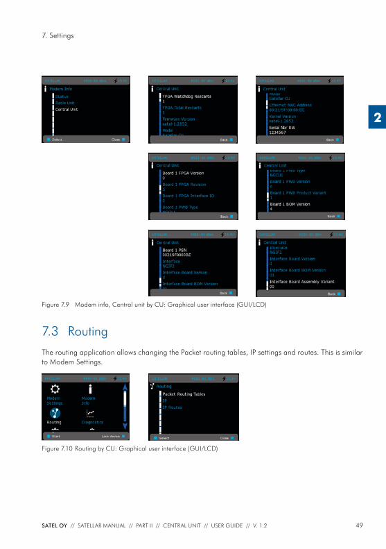
Figure 7.9 Modem info, Central unit by CU: Graphical user interface (GUI/LCD)
7.3 RoutingThe routing application allows changing the Packet routing tables, IP settings and routes. This is similar to Modem Settings.
Figure 7.10 Routing by CU: Graphical user interface (GUI/LCD)
50 SATEL OY // SATELLAR MANUAL // PART II // CENTRAL UNIT // USER GUIDE // V. 1.2
7. Settings
2
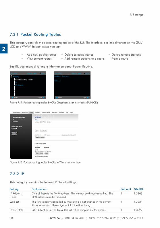
7.3.1 Packet Routing Tables
This category controls the packet routing tables of the RU. The interface is a little different on the GUI/LCD and WWW. In both cases you can:
– Add new packet routes – View current routes
See RU user manual for more information about Packet Routing.
Figure 7.11 Packet routing tables by CU: Graphical user interface (GUI/LCD)
7.3.2 IP
This category contains the Internet Protocol settings.
Setting Explanation Sub unit NMSID
IP Address 0 and 1
One of these is the Tun0 address. This cannot be directly modifi ed. The Eth0 address can be modifi ed.
1 1.3208
QoS set The functionality controlled by this setting is not fi nished in the current fi rmware version. Please ignore it for the time being.
1 1.3227
DHCP State OFF, Client or Server. Default is OFF. See chapter 6.2 for details. 1 1.3229
– Delete selected routes – Add remote stations to a route
– Delete remote stations from a route
Figure 7.12 Packet routing tables by CU: WWW user interface
51SATEL OY // SATELLAR MANUAL // PART II // CENTRAL UNIT // USER GUIDE // V. 1.2
7. Settings
2
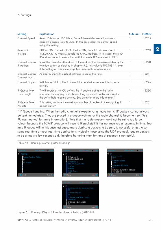
Setting Explanation Sub unit NMSID
Ethernet Speed Auto, 10 Mbps or 100 Mbps. Some Ethernet devices will not work correctly if speed is set to Auto. In this case select the correct speed using this setting.
1 1.3255
Automatic IP State
OFF or ON. Default is OFF. If set to ON, the eth0 address is set to 172.20.X.1/14, where X equals the RMAC address. In this case, the eth0 IP address cannot be modifi ed until Automatic IP State is set to OFF.
1 1.3263
Ethernet Current IP Address
Show the current eth0 address. If the address has been overridden by the function button as detailed in chapter 5.5, this value is 192.168.1.1, even if the setting on this same page has been set to another value.
1 1.3270
Ethernet Current Ethernet mask
As above, shows the actual netmask in use at this time. 1 1.3271
Ethernet Duplex Settable to FULL or HALF. Some Ethernet devices require this to be set to Half.
1 1.3276
IP Queue Max Time Length
The IP router of the CU buffers the IP packets going to the radio interface. This setting controls how long individual packets are kept in the buffer before being deleted. See below for more information.*
1 1.3280
IP Queue Max Packets
This setting controls the maximum number of packets in the outgoing IP packet buffer.*
1 1.3281
* IP Queue handling: When the radio channel is experiencing heavy traffi c, IP packets cannot always be sent immediately. They are placed in a queue waiting for the radio channel to become free. (See RU user manual for more information). Note that the radio queue should not be set to too large values, because the TCP/IP protocol will resend IP packets if it has not received a response in time. Too long IP queue will in this case just cause more duplicate packets to be sent, to no useful effect. Also some real-time or near-real-time applications, typically those using the UDP protocol, require packets to be at most a few seconds old, therefore buffering them for tens of seconds is not useful.
Table 7.8 Routing, Internet protocol settings
Figure 7.13 Routing, IP by CU: Graphical user interface (GUI/LCD)
52 SATEL OY // SATELLAR MANUAL // PART II // CENTRAL UNIT // USER GUIDE // V. 1.2
7. Settings
2
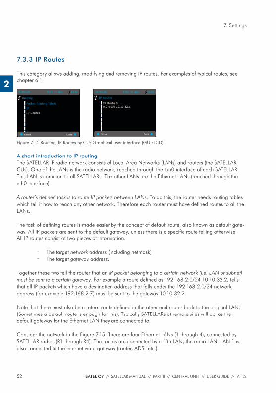
7.3.3 IP Routes
This category allows adding, modifying and removing IP routes. For examples of typical routes, see chapter 6.1.
Figure 7.14 Routing, IP Routes by CU: Graphical user interface (GUI/LCD)
A short introduction to IP routingThe SATELLAR IP radio network consists of Local Area Networks (LANs) and routers (the SATELLAR CUs). One of the LANs is the radio network, reached through the tun0 interface of each SATELLAR. This LAN is common to all SATELLARs. The other LANs are the Ethernet LANs (reached through the eth0 interface).
A router’s defi ned task is to route IP packets between LANs. To do this, the router needs routing tables which tell it how to reach any other network. Therefore each router must have defi ned routes to all the LANs.
The task of defi ning routes is made easier by the concept of default route, also known as default gate-way. All IP packets are sent to the default gateway, unless there is a specifi c route telling otherwise.All IP routes consist of two pieces of information.
– The target network address (including netmask) – The target gateway address.
Together these two tell the router that an IP packet belonging to a certain network (i.e. LAN or subnet) must be sent to a certain gateway. For example a route defi ned as 192.168.2.0/24 10.10.32.2, tells that all IP packets which have a destination address that falls under the 192.168.2.0/24 network address (for example 192.168.2.7) must be sent to the gateway 10.10.32.2.
Note that there must also be a return route defi ned in the other end router back to the original LAN. (Sometimes a default route is enough for this). Typically SATELLARs at remote sites will act as the default gateway for the Ethernet LAN they are connected to.
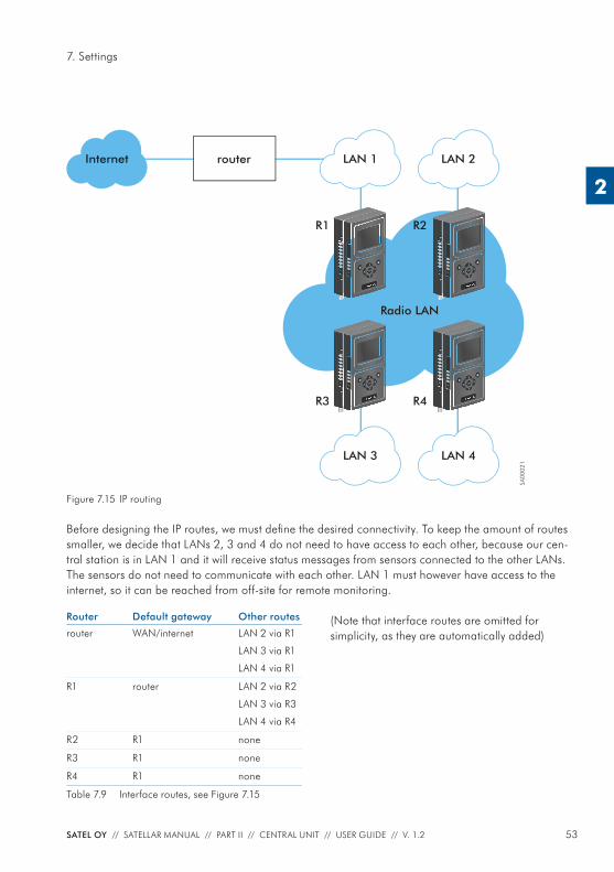
Consider the network in the Figure 7.15. There are four Ethernet LANs (1 through 4), connected by SATELLAR radios (R1 through R4). The radios are connected by a fi fth LAN, the radio LAN. LAN 1 is also connected to the internet via a gateway (router, ADSL etc.).
53SATEL OY // SATELLAR MANUAL // PART II // CENTRAL UNIT // USER GUIDE // V. 1.2
7. Settings
2
Internet router
R1 R2
R3 R4
Radio LAN
SA00
021
TD
RD
PWR
STAT
RX
TX
CTS
RTS
USB
ETH
PWR
STAT
OK
TD
RD
PWR
STAT
RX
TX
CTS
RTS
USB
ETH
PWR
STAT
OK
TD
RD
PWR
STAT
RX
TX
CTS
RTS
USB
ETH
PWR
STAT
OK
TD
RD
PWR
STAT
RX
TX
CTS
RTS
USB
ETH
PWR
STAT
OK
LAN 1 LAN 2
LAN 3 LAN 4
Figure 7.15 IP routing
Before designing the IP routes, we must defi ne the desired connectivity. To keep the amount of routes smaller, we decide that LANs 2, 3 and 4 do not need to have access to each other, because our cen-tral station is in LAN 1 and it will receive status messages from sensors connected to the other LANs. The sensors do not need to communicate with each other. LAN 1 must however have access to the internet, so it can be reached from off-site for remote monitoring.
Router Default gateway Other routes
router WAN/internet LAN 2 via R1
LAN 3 via R1
LAN 4 via R1
R1 router LAN 2 via R2
LAN 3 via R3
LAN 4 via R4
R2 R1 none
R3 R1 none
R4 R1 none
Table 7.9 Interface routes, see Figure 7.15
(Note that interface routes are omitted for simplicity, as they are automatically added)
54 SATEL OY // SATELLAR MANUAL // PART II // CENTRAL UNIT // USER GUIDE // V. 1.2
7. Settings
2
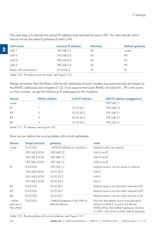
The next step is to decide the actual IP address and netmask for each LAN. You also decide which device will be the default gateway of each LAN.
LAN name network IP address Netmask Default gateway
LAN 1 192.168.1.0 24 router
LAN 2 192.168.2.0 24 R2
LAN 3 192.168.3.0 24 R3
LAN 4 192.168.4.0 24 R4
Radio LAN (Automatic) 10.10.32.0 19 R1
Table 7.10 IP address and net mask, see Figure 7.15
Please remember that the Radio LAN (tun0) addresses of each modem are automatically set based on the RMAC addresses (see chapter 6.1.2). If we assume that each RMAC of radios R1…R4 is the same as their number, we get the following IP addresses for the modems:
Device RMAC address tun0 IP address eth0 IP address (suggestion)
router - - 192.168.1.1
R1 1 10.10.32.1 192.168.1.2
R2 2 10.10.32.2 192.168.2.1
R3 3 10.10.32.3 192.168.3.1
R4 4 10.10.32.4 192.168.4.1
Table 7.11 IP address, see Figure 7.15
Now we can defi ne the routing tables with actual addresses:
Device Target network gateway notes
router 0.0.0.0/0 <WAN IP address or interface> Default route is to internet
192.168.2.0/24 192.168.1.2 LAN 2 via R1
192.168.3.0/24 192.168.1.2 LAN 3 via R1
192.168.4.0/24 192.168.1.2 LAN 4 via R1
R1 0.0.0.0/0 192.168.1.1 Default route is via the router to internet
192.168.2.0/24 10.10.32.2 LAN 2
192.168.3.0/24 10.10.32.3 LAN 3
192.168.4.0/24 10.10.32.4 LAN 4
R2 0.0.0.0/0 10.10.32.1 Default route is via the radio network to R1
R3 0.0.0.0/0 10.10.32.1 Default route is via the radio network to R1
R4 0.0.0.0/0 10.10.32.1 Default route is via the radio network to R1
<other devices in the LANs>
0.0.0.0/0 <default gateway of the LAN as defi ned above>
We omit the details, but in principle each device in LANs 2, 3 and 4 will set the SATELLAR as their default gateway. Devices in LAN 1 use router as their default gateway.
Table 7.12 Routing tables with actual address, see Figure 7.15
55SATEL OY // SATELLAR MANUAL // PART II // CENTRAL UNIT // USER GUIDE // V. 1.2
7. Settings
2
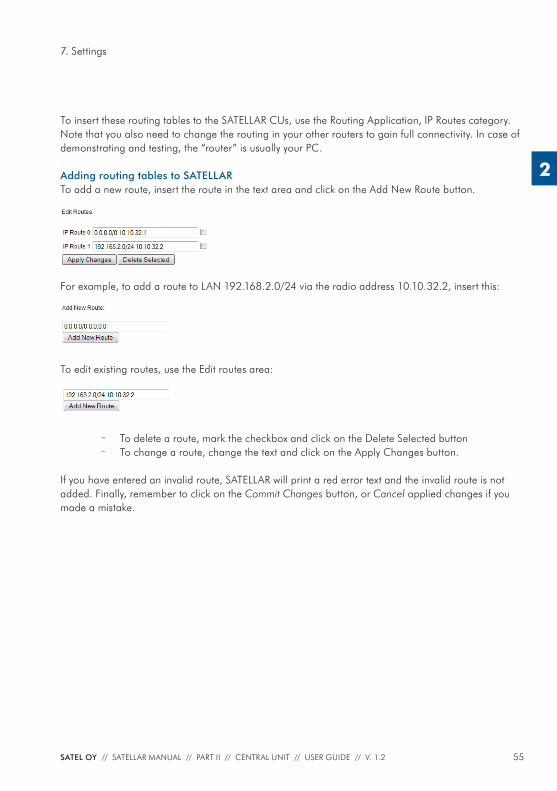
To insert these routing tables to the SATELLAR CUs, use the Routing Application, IP Routes category. Note that you also need to change the routing in your other routers to gain full connectivity. In case of demonstrating and testing, the “router” is usually your PC.
Adding routing tables to SATELLARTo add a new route, insert the route in the text area and click on the Add New Route button.
For example, to add a route to LAN 192.168.2.0/24 via the radio address 10.10.32.2, insert this:
To edit existing routes, use the Edit routes area:
– To delete a route, mark the checkbox and click on the Delete Selected button – To change a route, change the text and click on the Apply Changes button.
If you have entered an invalid route, SATELLAR will print a red error text and the invalid route is not added. Finally, remember to click on the Commit Changes button, or Cancel applied changes if you made a mistake.
56 SATEL OY // SATELLAR MANUAL // PART II // CENTRAL UNIT // USER GUIDE // V. 1.2
7. Settings
2
7.4 Serial IPSerial IP is a feature where data coming from serial port is converted to IP packets and set to des-ignated IP address. Correspondingly the received IP packets are converted and forwarded to serial interface. Serial IP confi guration handling is divided into two sections for two interfaces:
– RS-232 connection in the radio unit (RU) and – USB-Serial dongle attached to USB-A port of the central unit (CU).
7.4.1 Serial IP RS-232 / USB-A
This section includes confi gurations related to both RS-232 and USB-A interface connection / serial IP functionality.
Attribute Explanation Sub unit NMSID
Serial IP Mode Server – Used typically in cases where the data transfer is initiated by some remote host. Uses both sending and receiving functionality.
1 3287
Client – Used typically in cases where most of data that is sent is originated from the serial port of this device. This can be e.g. some on-demand service where data is sent whenever there is something to be sent. Uses both sending and receiving functionality.
Send Only - In this mode device is able only to send data to from serial port to defi ned IP address and port i.e. not able to receive any sending.
Receive Only – In this mode device is able to only receive data to defi ned IP listening port and forward it to serial port .
Port Rate Rate of serial port – from 1200 to 460800 bps. Default is 19200.
1 3288
Port Data Bits Serial Port Data Bits - 7 or 8. 1 3289
Port Parity Serial Port Parity - No Parity, Odd, Even. 1 3290
Port Stop Bits Serial Port Stop Bits – 1 bit or 2 bits. 1 3291
Protocol TCP, UDP, Telnet or Bulk Mode. Must be coherent in network.
1 3292
Listening Port IP Port for listening incoming messages. * 1 3293
Sending Port IP Port for sending outgoing messages. ** 1 3294
Sender Target Address IP address for sending outgoing messages. ** 1 3295
Sender Retry Count Count for how many times messages are attempted to resent in TCP protocol if send does not succeed. ***
1 3296
Sender Retry Interval The gap time between resending attempts (in TCP mode) in milliseconds. ***
1 3297
57SATEL OY // SATELLAR MANUAL // PART II // CENTRAL UNIT // USER GUIDE // V. 1.2
7. Settings
2
Attribute Explanation Sub unit NMSID
UDP Listener Port Timeout Timeout for releasing the listener of one connection in UDP mode in seconds. This means that if there is no data received in defi ned time, connection is closed. New connection can be established at any time again. ****
1 3298
Remote Control Port Mode Defi nes whether the RFC 2217 confi guration possibility set on or off, default being off.
1 3299
Remote Control Port Rate Port rate of remote control connection. Default is 115200. 1 3300
Remote Control Port IP port of confi guration. 1 3301
* Parameter is effective when message listening is on (Server, Client, Receive Only).** Parameter is effective when message sending is on (Server, Client, Send Only).*** Parameter is effective when message sending is on (Server, Client, Send Only) with TCP protocol.**** Parameter is effective when message listening is on (Server, Client, Receive Only) with UDP protocol.
Table 7.13 The confi gurations related to both RS-232 and USB-A interface connection / serial IP functionality
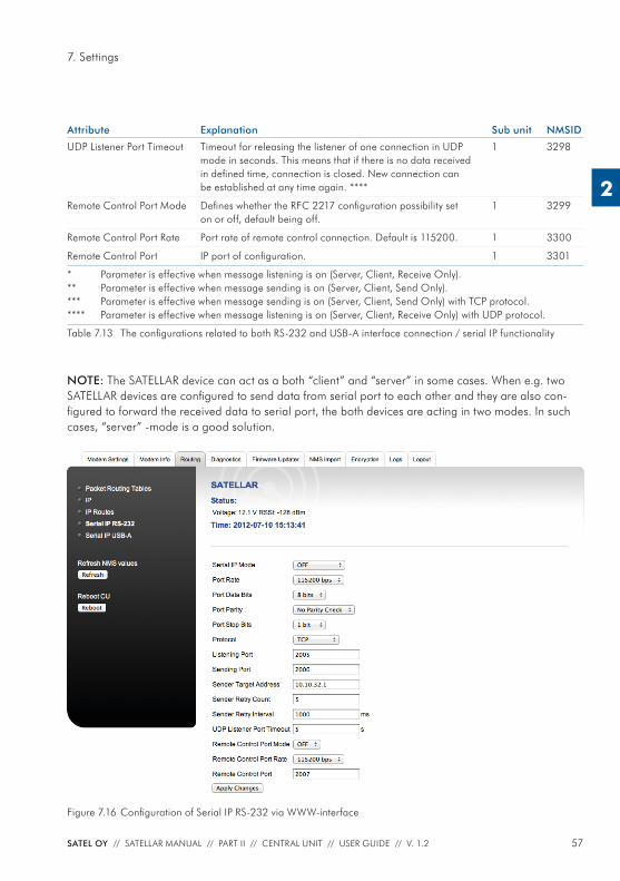
NOTE: The SATELLAR device can act as a both “client” and “server” in some cases. When e.g. two SATELLAR devices are confi gured to send data from serial port to each other and they are also con-fi gured to forward the received data to serial port, the both devices are acting in two modes. In such cases, “server” -mode is a good solution.
Figure 7.16 Confi guration of Serial IP RS-232 via WWW-interface
58 SATEL OY // SATELLAR MANUAL // PART II // CENTRAL UNIT // USER GUIDE // V. 1.2
7. Settings
2
7.4.2 Examples
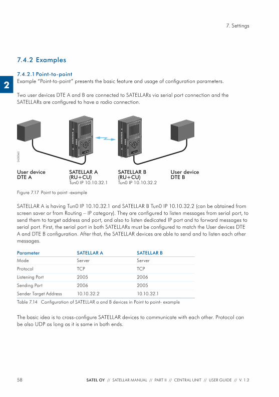
7.4.2.1 Point-to-pointExample “Point-to-point” presents the basic feature and usage of confi guration parameters.
Two user devices DTE A and B are connected to SATELLARs via serial port connection and the SATELLARs are confi gured to have a radio connection.
SA00
060
SATELLAR B(RU+CU)Tun0 IP 10.10.32.2
SATELLAR A(RU+CU)Tun0 IP 10.10.32.1
User deviceDTE B
User deviceDTE A
TD
RD
PWR
STAT
RX
TX
CTS
RTS
USB
ETH
PWR
STAT
OK
TD
RD
PWR
STAT
RX
TX
CTS
RTS
USB
ETH
PWR
STAT
OK
Figure 7.17 Point to point -example
SATELLAR A is having Tun0 IP 10.10.32.1 and SATELLAR B Tun0 IP 10.10.32.2 (can be obtained from screen saver or from Routing – IP category). They are confi gured to listen messages from serial port, to send them to target address and port, and also to listen dedicated IP port and to forward messages to serial port. First, the serial port in both SATELLARs must be confi gured to match the User devices DTE A and DTE B confi guration. After that, the SATELLAR devices are able to send and to listen each other messages.
Parameter SATELLAR A SATELLAR B
Mode Server Server
Protocol TCP TCP
Listening Port 2005 2006
Sending Port 2006 2005
Sender Target Address 10.10.32.2 10.10.32.1
Table 7.14 Confi guration of SATELLAR a and B devices in Point to point- example
The basic idea is to cross-confi gure SATELLAR devices to communicate with each other. Protocol can be also UDP as long as it is same in both ends.
59SATEL OY // SATELLAR MANUAL // PART II // CENTRAL UNIT // USER GUIDE // V. 1.2
7. Settings
2
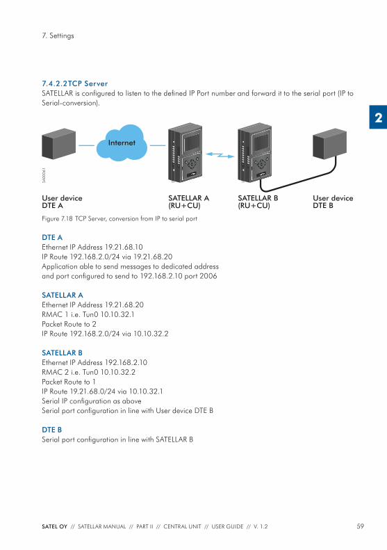
7.4.2.2 TCP ServerSATELLAR is confi gured to listen to the defi ned IP Port number and forward it to the serial port (IP to Serial-conversion).
SA00
061
SATELLAR B(RU+CU)
SATELLAR A(RU+CU)
User deviceDTE B
User deviceDTE A
TD
RD
PWR
STAT
RX
TX
CTS
RTS
USB
ETH
PWR
STAT
OK
TD
RD
PWR
STAT
RX
TX
CTS
RTS
USB
ETH
PWR
STAT
OK
Internet
Figure 7.18 TCP Server, conversion from IP to serial port
DTE AEthernet IP Address 19.21.68.10IP Route 192.168.2.0/24 via 19.21.68.20Application able to send messages to dedicated address and port confi gured to send to 192.168.2.10 port 2006
SATELLAR AEthernet IP Address 19.21.68.20RMAC 1 i.e. Tun0 10.10.32.1Packet Route to 2IP Route 192.168.2.0/24 via 10.10.32.2
SATELLAR BEthernet IP Address 192.168.2.10RMAC 2 i.e. Tun0 10.10.32.2Packet Route to 1IP Route 19.21.68.0/24 via 10.10.32.1Serial IP confi guration as aboveSerial port confi guration in line with User device DTE B
DTE BSerial port confi guration in line with SATELLAR B
60 SATEL OY // SATELLAR MANUAL // PART II // CENTRAL UNIT // USER GUIDE // V. 1.2
7. Settings
2
User Device DTE A has an Ethernet IP address 19.21.68.10. SATELLAR B has two IP addresses Tun0 10.10.32.2 and Eth0 192.168.2.10 which both can be used depending on the routing confi guration in User device DTE A. Ethernet address is used in this example.
SATELLAR A do not have any Serial IP connection and it is confi gured to have radio connection with SATELLAR B. User device DTE A must be set to route messages to SATELLAR B via SATELLAR A. In this case SATELLAR A has an IP 19.21.68.20, User device DTE A must have a route 192.168.2.0/24 via 19.21.68.20 and must also have an application able to send messages to dedicated address and port, in this case to port 2006 at 192.168.2.10.
Parameter SATELLAR B
Mode Server
Protocol TCP
Listening Port 2006
Table 7.15 Serial port confi curation of SATELLAR B
Sending parameters are not necessary, since TCP is capable of sending replies back when connection has been opened.
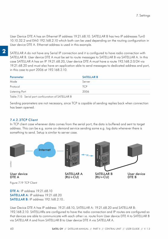
7.4.2.3 TCP ClientIn TCP client case whenever data comes from the serial port, the data is buffered and sent to target address. This can be e.g. some on-demand service sending some e.g. log data whenever there is something to send. Setup is similar to server case.
SA00
061
SATELLAR B(RU+CU)
SATELLAR A(RU+CU)
User deviceDTE B
User deviceDTE A
TD
RD
PWR
STAT
RX
TX
CTS
RTS
USB
ETH
PWR
STAT
OK
TD
RD
PWR
STAT
RX
TX
CTS
RTS
USB
ETH
PWR
STAT
OK
Internet
Figure 7.19 TCP Client
DTE A: IP address 19.21.68.10SATELLAR A: IP address 19.21.68.20 SATELLAR B: IP address 192.168.2.10..
User Device DTE A has IP address: 19.21.68.10, SATELLAR A: 19.21.68.20 and SATELLAR B: 192.168.2.10. SATELLARs are confi gured to have the radio connection and IP routes are confi gured so that devices are able to communicate with each other i.e. route from User device DTE A to SATELLAR B via SATELLAR A and from SATELLAR B to User device DTE A via SATELLAR A.
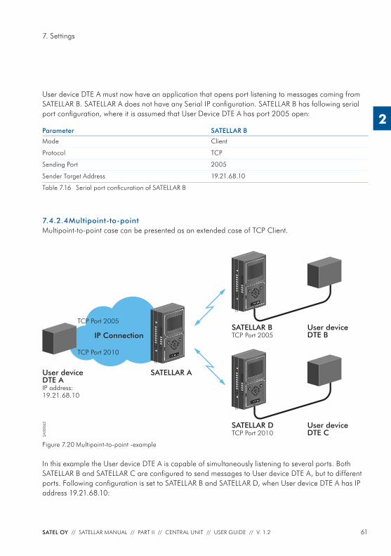
61SATEL OY // SATELLAR MANUAL // PART II // CENTRAL UNIT // USER GUIDE // V. 1.2
7. Settings
2
User device DTE A must now have an application that opens port listening to messages coming from SATELLAR B. SATELLAR A does not have any Serial IP confi guration. SATELLAR B has following serial port confi guration, where it is assumed that User Device DTE A has port 2005 open:
Parameter SATELLAR B
Mode Client
Protocol TCP
Sending Port 2005
Sender Target Address 19.21.68.10
Table 7.16 Serial port confi curation of SATELLAR B
7.4.2.4 Multipoint-to-pointMultipoint-to-point case can be presented as an extended case of TCP Client.
SA00
062 SATELLAR D
TCP Port 2010
SATELLAR A
User deviceDTE C
User deviceDTE AIP address:19.21.68.10
TD
RD
PWR
STAT
RX
TX
CTS
RTS
USB
ETH
PWR
STAT
OK
SATELLAR BTCP Port 2005
User deviceDTE B
TD
RD
PWR
STAT
RX
TX
CTS
RTS
USB
ETH
PWR
STAT
OK
IP Connection TD
RD
PWR
STAT
RX
TX
CTS
RTS
USB
ETH
PWR
STAT
OK
TCP Port 2010
TCP Port 2005
Figure 7.20 Multipoint-to-point -example
In this example the User device DTE A is capable of simultaneously listening to several ports. Both SATELLAR B and SATELLAR C are confi gured to send messages to User device DTE A, but to different ports. Following confi guration is set to SATELLAR B and SATELLAR D, when User device DTE A has IP address 19.21.68.10:
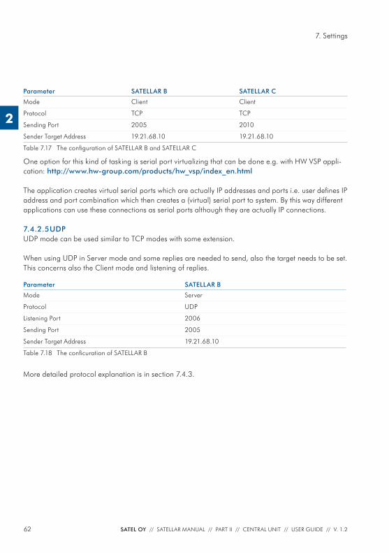
62 SATEL OY // SATELLAR MANUAL // PART II // CENTRAL UNIT // USER GUIDE // V. 1.2
7. Settings
2
Parameter SATELLAR B SATELLAR C
Mode Client Client
Protocol TCP TCP
Sending Port 2005 2010
Sender Target Address 19.21.68.10 19.21.68.10
Table 7.17 The confi guration of SATELLAR B and SATELLAR C
One option for this kind of tasking is serial port virtualizing that can be done e.g. with HW VSP appli-cation: http://www.hw-group.com/products/hw_vsp/index_en.html
The application creates virtual serial ports which are actually IP addresses and ports i.e. user defi nes IP address and port combination which then creates a (virtual) serial port to system. By this way different applications can use these connections as serial ports although they are actually IP connections.
7.4.2.5 UDPUDP mode can be used similar to TCP modes with some extension.
When using UDP in Server mode and some replies are needed to send, also the target needs to be set. This concerns also the Client mode and listening of replies.
Parameter SATELLAR B
Mode Server
Protocol UDP
Listening Port 2006
Sending Port 2005
Sender Target Address 19.21.68.10
Table 7.18 The confi curation of SATELLAR B
More detailed protocol explanation is in section 7.4.3.
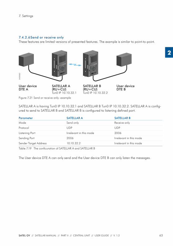
63SATEL OY // SATELLAR MANUAL // PART II // CENTRAL UNIT // USER GUIDE // V. 1.2
7. Settings
2
7.4.2.6 Send or receive onlyThese features are limited versions of presented features. The example is similar to point-to-point.
SA00
060
SATELLAR B(RU+CU)Tun0 IP 10.10.32.2
SATELLAR A(RU+CU)Tun0 IP 10.10.32.1
User deviceDTE B
User deviceDTE A
TD
RD
PWR
STAT
RX
TX
CTS
RTS
USB
ETH
PWR
STAT
OK
TD
RD
PWR
STAT
RX
TX
CTS
RTS
USB
ETH
PWR
STAT
OK
Figure 7.21 Send or receive only -example
SATELLAR A is having Tun0 IP 10.10.32.1 and SATELLAR B Tun0 IP 10.10.32.2. SATELLAR A is confi g-ured to send to SATELLAR B and SATELLAR B is confi gured to listening defi ned port.
Parameter SATELLAR A SATELLAR B
Mode Send only Receive only
Protocol UDP UDP
Listening Port Irrelevant in this mode 2006
Sending Port 2006 Irrelevant in this mode
Sender Target Address 10.10.32.2 Irrelevant in this mode
Table 7.19 The confi curation of SATELLAR A and SATELLAR B
The User device DTE A can only send and the User device DTE B can only listen the messages.
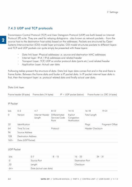
64 SATEL OY // SATELLAR MANUAL // PART II // CENTRAL UNIT // USER GUIDE // V. 1.2
7. Settings
2
7.4.3 UDP and TCP protocols
Transmission Control Protocol (TCP) and User Datagram Protocol (UDP) are both based on Internet Protocol (IP) suite. They are used for relaying datagrams - also known as network packets – from the source host to the destination host solely based on the addresses. Packets are structured by Open Systems Interconnection (OSI) model layer principles. OSI model structures packets to different layers and TCP and UDP packets can quite simply be presented with these layers:
– Data link layer: Physical addresses i.e. source and destination MAC addresses – Internet layer: IPv4 / IPv6 addresses and related header – Transport Layer: TCP, UDP or similar protocol data (ports etc.) and related header – Application Layer: Actual user data
Following tables present the structure of data. Data link layer data comes fi rst and in the end there is frame footer. Between the frame data and footer is IP packet data. In IP packet internet layer data is fi rst, then the transport layer i.e. protocol related data and fi nally actual user data.
Data Link layer
Frame header (8 bytes) Frame data (14 bytes) IP + UDP packet (below) Frame footer i.e. CRC (4 bytes)
IP Packet
bits 0-3 4-7 8-13 14-15 16-18 19-31
0 Version Internet Header Length
Differentiated Services Code Point
Explicit Congestion Notifi cation
Total Length
32 Identifi cation Flags Fragment Offset
64 Time To Live Protocol Header Checksum
96 Source Address
128 Destination Address
160+ Data (UDP Packet)
UDP Packet
bits 0-7 8 – 15 16 – 23 24 – 31
0 Source Port Destination Port
32 Length Checksum
64+ Data (actual user data)
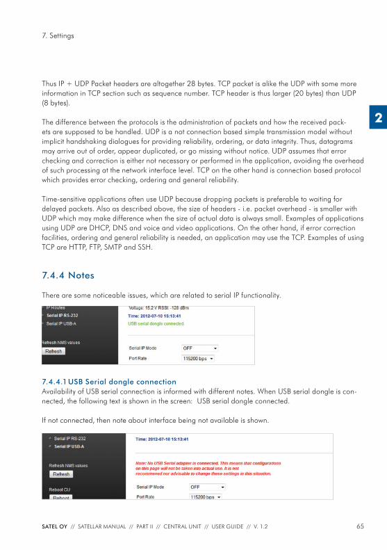
65SATEL OY // SATELLAR MANUAL // PART II // CENTRAL UNIT // USER GUIDE // V. 1.2
7. Settings
2
Thus IP + UDP Packet headers are altogether 28 bytes. TCP packet is alike the UDP with some more information in TCP section such as sequence number. TCP header is thus larger (20 bytes) than UDP (8 bytes).
The difference between the protocols is the administration of packets and how the received pack-ets are supposed to be handled. UDP is a not connection based simple transmission model without implicit handshaking dialogues for providing reliability, ordering, or data integrity. Thus, datagrams may arrive out of order, appear duplicated, or go missing without notice. UDP assumes that error checking and correction is either not necessary or performed in the application, avoiding the overhead of such processing at the network interface level. TCP on the other hand is connection based protocol which provides error checking, ordering and general reliability.
Time-sensitive applications often use UDP because dropping packets is preferable to waiting for delayed packets. Also as described above, the size of headers - i.e. packet overhead - is smaller with UDP which may make difference when the size of actual data is always small. Examples of applications using UDP are DHCP, DNS and voice and video applications. On the other hand, if error correction facilities, ordering and general reliability is needed, an application may use the TCP. Examples of using TCP are HTTP, FTP, SMTP and SSH.
7.4.4 Notes
There are some noticeable issues, which are related to serial IP functionality.
7.4.4.1 USB Serial dongle connectionAvailability of USB serial connection is informed with different notes. When USB serial dongle is con-nected, the following text is shown in the screen: USB serial dongle connected.
If not connected, then note about interface being not available is shown.
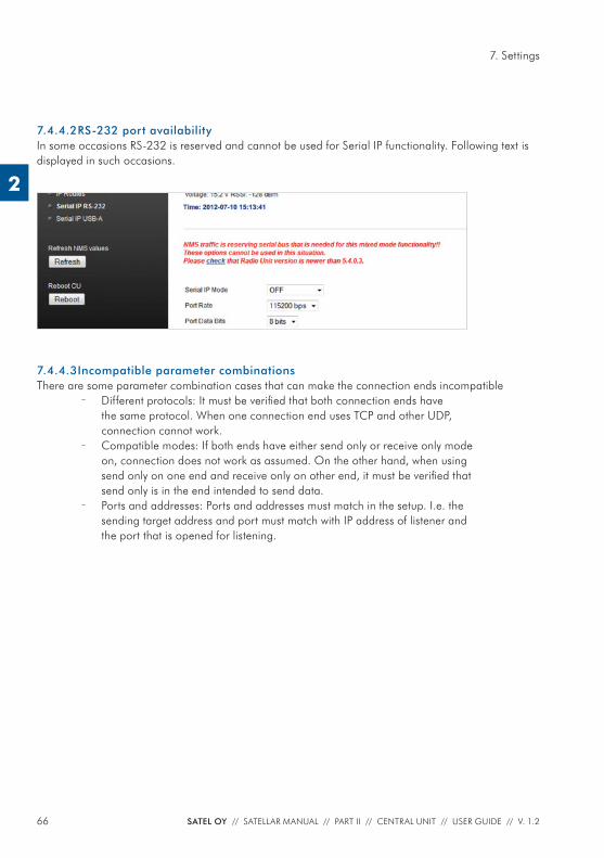
66 SATEL OY // SATELLAR MANUAL // PART II // CENTRAL UNIT // USER GUIDE // V. 1.2
7. Settings
2
7.4.4.2 RS-232 port availabilityIn some occasions RS-232 is reserved and cannot be used for Serial IP functionality. Following text is displayed in such occasions.
7.4.4.3 Incompatible parameter combinationsThere are some parameter combination cases that can make the connection ends incompatible
– Different protocols: It must be verifi ed that both connection ends have the same protocol. When one connection end uses TCP and other UDP, connection cannot work.
– Compatible modes: If both ends have either send only or receive only mode on, connection does not work as assumed. On the other hand, when using send only on one end and receive only on other end, it must be verifi ed that send only is in the end intended to send data.
– Ports and addresses: Ports and addresses must match in the setup. I.e. the sending target address and port must match with IP address of listener and the port that is opened for listening.
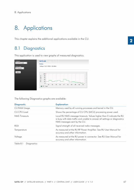
67SATEL OY // SATELLAR MANUAL // PART II // CENTRAL UNIT // USER GUIDE // V. 1.2
8. Applications
2
8. Applications
This chapter explains the additional applications available in the CU.
8.1 DiagnosticsThis application is used to view graphs of measured diagnostics.
The following Diagnostics graphs are available:
Diagnostic Explanation
CU RAM Usage Memory used by all running processes and kernel in the CU.
CU CPU Load Shows the percentage of CU CPU (MCU) processing power used.
NMS Timeouts Local RU NMS message timeouts. Values higher than 0 indicate the RU is busy with data traffi c and unable to answer all settings or diagnostics NMS messages sent by the CU.
RSSI Signal strength of all received radio messages.
Temperature As measured at the RU RF Power Amplifi er. See RU User Manual for accuracy and other information.
Voltage As measured at the RU power in connector. See RU User Manual for accuracy and other information.
Table 8.1 Diagnostics
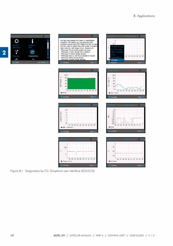
68 SATEL OY // SATELLAR MANUAL // PART II // CENTRAL UNIT // USER GUIDE // V. 1.2
8. Applications
2
Figure 8.1 Diagnostics by CU: Graphical user interface (GUI/LCD)
69SATEL OY // SATELLAR MANUAL // PART II // CENTRAL UNIT // USER GUIDE // V. 1.2
8. Applications
2
8.2 Simple Network Management Protocol (SNMP) An “Internet-standard protocol for managing devices on IP networks.” It is used mostly in network management systems to monitor network-attached devices for conditions that warrant administrative attention. SNMP is simply a protocol for collecting and organizing information. SNMP itself does not defi ne which information (which variables) a managed system should offer. Rather, SNMP uses an extensible design, where the available information is defi ned by management information bases .
In typical SNMP uses, one or more administrative computers, called managers, have the task of moni-toring or managing devices on a network. Each managed system executes, at all times, a software component called an agent which reports information via SNMP to the manager.
Essentially, SNMP agents expose management data on the managed systems as variables. The protocol also permits active management tasks, such as modifying and applying a new confi guration through remote modifi cation of these variables.
An SNMP-managed network consists of three key components:
– Managed device – Agent — software which runs on managed devices – Network management system (NMS) — software which runs on the manager
Typical radio modem or system monitoring can be RSSI-values, Voltage or Temperature. Setting type confi guration consists of IP- or radio parameters.
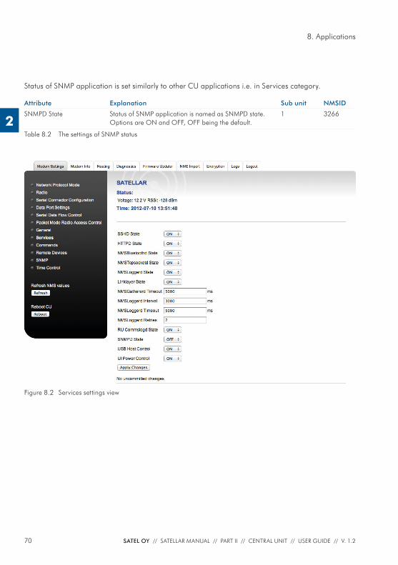
70 SATEL OY // SATELLAR MANUAL // PART II // CENTRAL UNIT // USER GUIDE // V. 1.2
8. Applications
2
Status of SNMP application is set similarly to other CU applications i.e. in Services category.
Attribute Explanation Sub unit NMSID
SNMPD State Status of SNMP application is named as SNMPD state. Options are ON and OFF, OFF being the default.
1 3266
Table 8.2 The settings of SNMP status
Figure 8.2 Services settings view
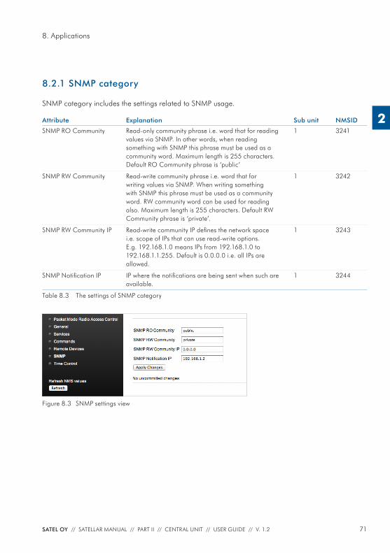
71SATEL OY // SATELLAR MANUAL // PART II // CENTRAL UNIT // USER GUIDE // V. 1.2
8. Applications
2
8.2.1 SNMP category
SNMP category includes the settings related to SNMP usage.
Attribute Explanation Sub unit NMSID
SNMP RO Community Read-only community phrase i.e. word that for reading values via SNMP. In other words, when reading something with SNMP this phrase must be used as a community word. Maximum length is 255 characters. Default RO Community phrase is ‘public’
1 3241
SNMP RW Community Read-write community phrase i.e. word that for writing values via SNMP. When writing something with SNMP this phrase must be used as a community word. RW community word can be used for reading also. Maximum length is 255 characters. Default RW Community phrase is ‘private’.
1 3242
SNMP RW Community IP Read-write community IP defi nes the network space i.e. scope of IPs that can use read-write options. E.g. 192.168.1.0 means IPs from 192.168.1.0 to 192.168.1.1.255. Default is 0.0.0.0 i.e. all IPs are allowed.
1 3243
SNMP Notifi cation IP IP where the notifi cations are being sent when such are available.
1 3244
Table 8.3 The settings of SNMP category
Figure 8.3 SNMP settings view
72 SATEL OY // SATELLAR MANUAL // PART II // CENTRAL UNIT // USER GUIDE // V. 1.2
8. Applications
2
8.2.2 MIB
MIB i.e. Management Information Base is a fi le that is used along the SNMP to defi ne the set of parameters that are available with SNMP. MIBs include hierarchical name space including individual parameters that called as OIDs - Object Identifi ers. SATELLAR has its own MIB but it needs two SATEL generic MIBs to be able to work with typical SNMP application hierarchy mechanisms. These MIBs are available at www.SATEL.com/downloads. Available parameters are basically the same as in GUIs and also defi ned similar way also (read-write or read-only). Parameters can be seen by browsing them with graphical SNMP applications after importing MIBs or e.g. with snmptranslate tool with following command.snmptranslate -Tp -IR satelBasic structure of MIB is following
– satelSATELLARNMS – satelSATELLARNMSInfo
– satelSATELLARNMSInfoRU – satelSATELLARNMSInfoCU
– satelSATELLARNMSSettings – satelSATELLARNMSSettingsRU – satelSATELLARNMSSettingsCU
– satelSATELLARNMSRouting – satelSATELLARNMSCancelCommit
These follow the idea of GUIs so that NMSInfo includes same parameters as Modem Info category, NMSSettings include same parameters as Modem Settings and NMSRouting same parameters as Routing category.
CancelCommit is an individual parameter and is used for making the saving functional analog to GUIs. When setting some parameter, user stores them into temporary storage in Satellar same way as they are applied in web GUI. To store the values permanently and make them effective, CancelCommit is set to value 1. To cancel settings that are not yet stored and to clear the temporary storage, CancelCommit is set to 0.
8.2.2.1 Applications, examplesNET-SNMP – Console based application for various SNMP usages.
Dude – a simple Windows-GUI application.
Spiceworks – a browser-based application.
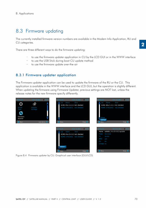
73SATEL OY // SATELLAR MANUAL // PART II // CENTRAL UNIT // USER GUIDE // V. 1.2
8. Applications
2
8.3 Firmware updatingThe currently installed fi rmware version numbers are available in the Modem Info Application, RU and CU categories.
There are three different ways to do the fi rmware updating:
– to use the fi rmware updater application in CU by the LCD GUI or in the WWW interface – to use the USB Stick during boot CU update method – to use the fi rmware update over-the-air
8.3.1 Firmware updater application
The Firmware updater application can be used to update the fi rmware of the RU or the CU. This application is available in the WWW interface and the LCD GUI, but the operation is slightly different.When updating the fi rmware using Firmware Updater, previous settings are NOT lost, unless the release notes for the new fi rmware specify differently.
Figure 8.4 Firmware updater by CU: Graphical user interface (GUI/LCD)
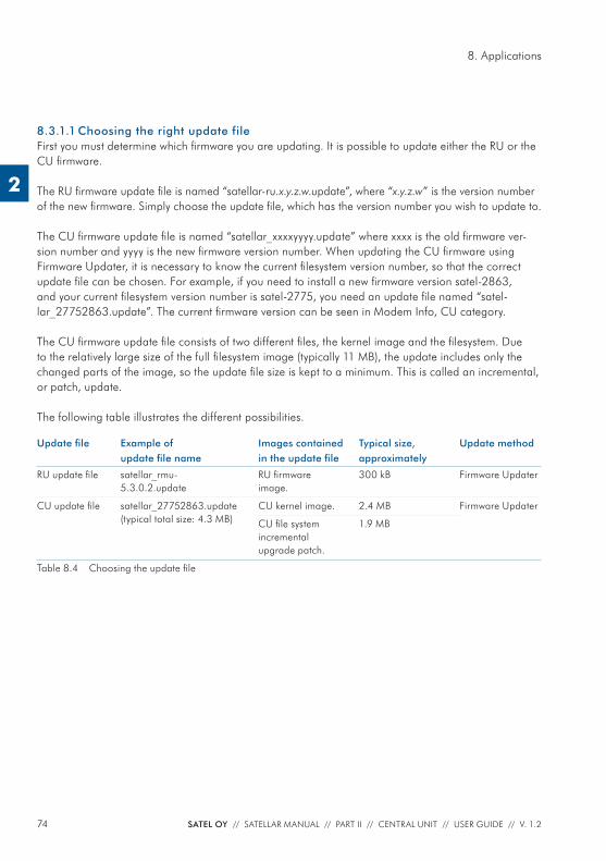
74 SATEL OY // SATELLAR MANUAL // PART II // CENTRAL UNIT // USER GUIDE // V. 1.2
8. Applications
2
8.3.1.1 Choosing the right update fileFirst you must determine which fi rmware you are updating. It is possible to update either the RU or the CU fi rmware.
The RU fi rmware update fi le is named “satellar-ru.x.y.z.w.update”, where “x.y.z.w” is the version number of the new fi rmware. Simply choose the update fi le, which has the version number you wish to update to.
The CU fi rmware update fi le is named “satellar_xxxxyyyy.update” where xxxx is the old fi rmware ver-sion number and yyyy is the new fi rmware version number. When updating the CU fi rmware using Firmware Updater, it is necessary to know the current fi lesystem version number, so that the correct update fi le can be chosen. For example, if you need to install a new fi rmware version satel-2863, and your current fi lesystem version number is satel-2775, you need an update fi le named “satel-lar_27752863.update”. The current fi rmware version can be seen in Modem Info, CU category.
The CU fi rmware update fi le consists of two different fi les, the kernel image and the fi lesystem. Due to the relatively large size of the full fi lesystem image (typically 11 MB), the update includes only the changed parts of the image, so the update fi le size is kept to a minimum. This is called an incremental, or patch, update.
The following table illustrates the different possibilities.
Update fi le Example of update fi le name
Images contained in the update fi le
Typical size, approximately
Update method
RU update fi le satellar_rmu-5.3.0.2.update
RU fi rmware image.
300 kB Firmware Updater
CU update fi le satellar_27752863.update(typical total size: 4.3 MB)
CU kernel image. 2.4 MB Firmware Updater
CU fi le system incremental upgrade patch.
1.9 MB
Table 8.4 Choosing the update fi le
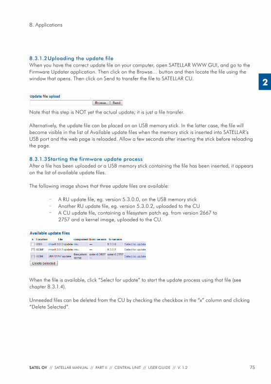
75SATEL OY // SATELLAR MANUAL // PART II // CENTRAL UNIT // USER GUIDE // V. 1.2
8. Applications
2
8.3.1.2 Uploading the update fileWhen you have the correct update fi le on your computer, open SATELLAR WWW GUI, and go to the Firmware Updater application. Then click on the Browse… button and then locate the fi le using the window that opens. Then click on Send to transfer the fi le to SATELLAR CU.
Note that this step is NOT yet the actual update; it is just a fi le transfer.
Alternatively, the update fi le can be placed on an USB memory stick. In the latter case, the fi le will become visible in the list of Available update fi les when the memory stick is inserted into SATELLAR’s USB port and the web page is reloaded. Allow a few seconds after inserting the stick before reloading the page.
8.3.1.3 Starting the firmware update processAfter a fi le has been uploaded or a USB memory stick containing the fi le has been inserted, it appears on the list of available update fi les.
The following image shows that three update fi les are available:
– A RU update fi le, eg. version 5.3.0.0, on the USB memory stick – Another RU update fi le, eg. version 5.3.0.2, uploaded to the CU – A CU update fi le, containing a fi lesystem patch eg. from version 2667 to
2757 and a kernel image, uploaded to the CU.
When the fi le is available, click “Select for update” to start the update process using that fi le (see chapter 8.3.1.4).
Unneeded fi les can be deleted from the CU by checking the checkbox in the “x” column and clicking “Delete Selected”.
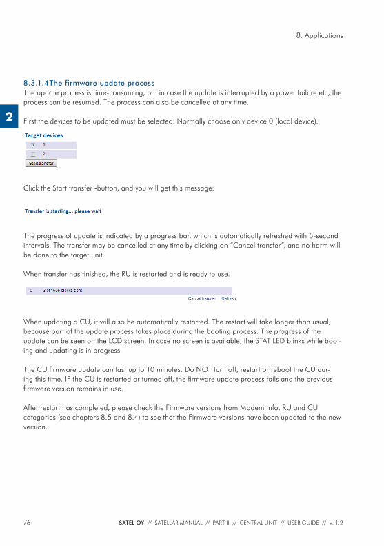
76 SATEL OY // SATELLAR MANUAL // PART II // CENTRAL UNIT // USER GUIDE // V. 1.2
8. Applications
2
8.3.1.4 The firmware update processThe update process is time-consuming, but in case the update is interrupted by a power failure etc, the process can be resumed. The process can also be cancelled at any time.
First the devices to be updated must be selected. Normally choose only device 0 (local device).
Click the Start transfer -button, and you will get this message:
The progress of update is indicated by a progress bar, which is automatically refreshed with 5-second intervals. The transfer may be cancelled at any time by clicking on “Cancel transfer”, and no harm will be done to the target unit. When transfer has fi nished, the RU is restarted and is ready to use.
When updating a CU, it will also be automatically restarted. The restart will take longer than usual; because part of the update process takes place during the booting process. The progress of the update can be seen on the LCD screen. In case no screen is available, the STAT LED blinks while boot-ing and updating is in progress.
The CU fi rmware update can last up to 10 minutes. Do NOT turn off, restart or reboot the CU dur-ing this time. IF the CU is restarted or turned off, the fi rmware update process fails and the previous fi rmware version remains in use.
After restart has completed, please check the Firmware versions from Modem Info, RU and CU categories (see chapters 8.5 and 8.4) to see that the Firmware versions have been updated to the new version.
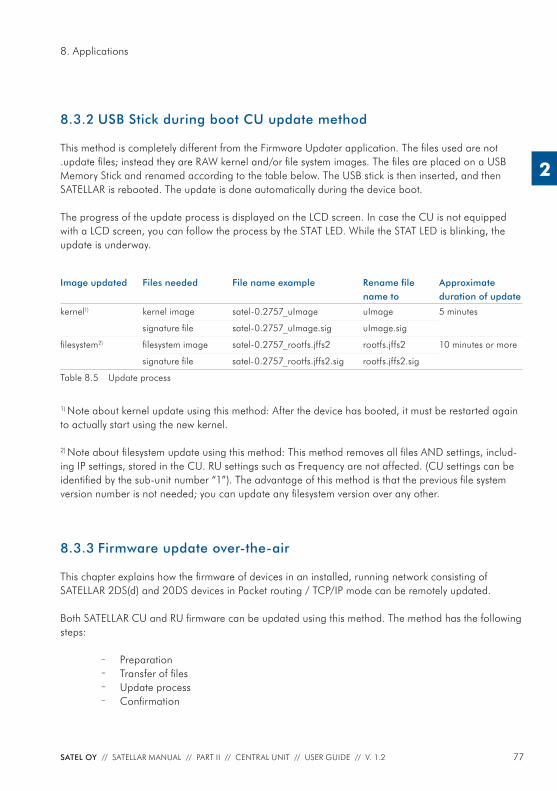
77SATEL OY // SATELLAR MANUAL // PART II // CENTRAL UNIT // USER GUIDE // V. 1.2
8. Applications
2
8.3.2 USB Stick during boot CU update method
This method is completely different from the Firmware Updater application. The fi les used are not .update fi les; instead they are RAW kernel and/or fi le system images. The fi les are placed on a USB Memory Stick and renamed according to the table below. The USB stick is then inserted, and then SATELLAR is rebooted. The update is done automatically during the device boot.
The progress of the update process is displayed on the LCD screen. In case the CU is not equipped with a LCD screen, you can follow the process by the STAT LED. While the STAT LED is blinking, the update is underway.
Image updated Files needed File name example Rename fi le name to
Approximate duration of update
kernel1) kernel image satel-0.2757_uImage uImage 5 minutes
signature fi le satel-0.2757_uImage.sig uImage.sig
fi lesystem2) fi lesystem image satel-0.2757_rootfs.jffs2 rootfs.jffs2 10 minutes or more
signature fi le satel-0.2757_rootfs.jffs2.sig rootfs.jffs2.sig
Table 8.5 Update process
1) Note about kernel update using this method: After the device has booted, it must be restarted again to actually start using the new kernel.
2) Note about fi lesystem update using this method: This method removes all fi les AND settings, includ-ing IP settings, stored in the CU. RU settings such as Frequency are not affected. (CU settings can be identifi ed by the sub-unit number “1”). The advantage of this method is that the previous fi le system version number is not needed; you can update any fi lesystem version over any other.
8.3.3 Firmware update over-the-air
This chapter explains how the fi rmware of devices in an installed, running network consisting of SATELLAR 2DS(d) and 20DS devices in Packet routing / TCP/IP mode can be remotely updated.
Both SATELLAR CU and RU fi rmware can be updated using this method. The method has the following steps:
– Preparation – Transfer of fi les – Update process – Confi rmation
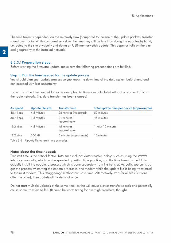
78 SATEL OY // SATELLAR MANUAL // PART II // CENTRAL UNIT // USER GUIDE // V. 1.2
8. Applications
2
The time taken is dependent on the relatively slow (compared to the size of the update packets) transfer speed over radio. While comparatively slow, the time may still be less than doing the updates by hand, i.e. going to the site physically and doing an USB-memory-stick update. This depends fully on the size and geography of the installed network.
8.3.3.1 Preparation stepsBefore starting the fi rmware update, make sure the following preconditions are fulfi lled.
Step 1. Plan the time needed for the update processYou should plan your update process so you know the downtime of the data system beforehand and can proceed with less uncertainty.
Table 1 lists the time needed for some examples. All times are calculated without any other traffi c in the radio network. (I.e. data transfer has been stopped)
Air speed Update fi le size Transfer time Total update time per device (approximate)
38.4 kbps 4.5 MBytes 28 minutes (measured) 50 minutes
38.4 kbps 3.5 MBytes 24 minutes (approximate)
45 minutes
19.2 kbps 4.5 MBytes 45 minutes (approximate)
1 hour 10 minutes
19.2 kbps 300 kB 5 minutes (approximate) 15 minutes
Table 8.6 Update fi le transmit time examples
Notes about the time needed:Transmit time is the critical factor. Total time includes data transfer, delays such as using the WWW interface manually, which can be speeded up with a little practice, and the time taken by the CU to actually install the update, a process which is done separately from fi le transfer. Actually, you can stag-ger the process by starting the update process in one modem while the update fi le is being transferred to the next modem. This “staggering” method can save time. Alternatively, transfer all fi les fi rst (one after the other), then update all modems at once.
Do not start multiple uploads at the same time, as this will cause slower transfer speeds and potentially cause some transfers to fail. (It could be worth trying for overnight transfers, though)
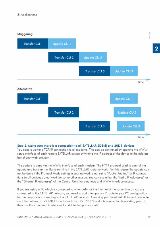
79SATEL OY // SATELLAR MANUAL // PART II // CENTRAL UNIT // USER GUIDE // V. 1.2
8. Applications
2
Time
Time
Staggering:
Alternative:
Transfer CU 1 Update CU 1
Update CU 1
Update CU 2
Update CU 2
Update CU 3
Update CU 3
Transfer CU 2
Transfer CU 2
Transfer CU 3
Transfer CU 3
Transfer CU 1
SA00
063
Step 2. Make sure there is a connection to all SATELLAR 2DS(d) and 20DS devicesYou need a working TCP/IP connection to all modems. This can be confi rmed by opening the WWW setup interface of each remote SATELLAR device by writing the IP address of the device in the address bar of your web browser.
The update is done via the WWW interface of each modem. The HTTP protocol used to control the update and transfer the fi les is running in the SATELLAR radio network. For this reason the update can-not be done if the Protocol Mode setting in your network is not set to “Packet Routing” or IP connec-tions to all devices do not work for some other reason. You can use either the “radio IP addresses” or the “Ethernet IP addresses” of the Central Units for ping tests and WWW interface access.
If you are using a PC which is connected to other LANs or the Internet at the same time as you are connected to the SATELLAR network, you need to add a temporary IP route to your PC confi guration for the purpose of connecting to the SATELLAR network. Assuming your local SATELLAR unit connected via Ethernet has IP 192.168.1.1 and your PC is 192.168.1.2 and this connection is working, you can then use this command in windows to add the temporary route:
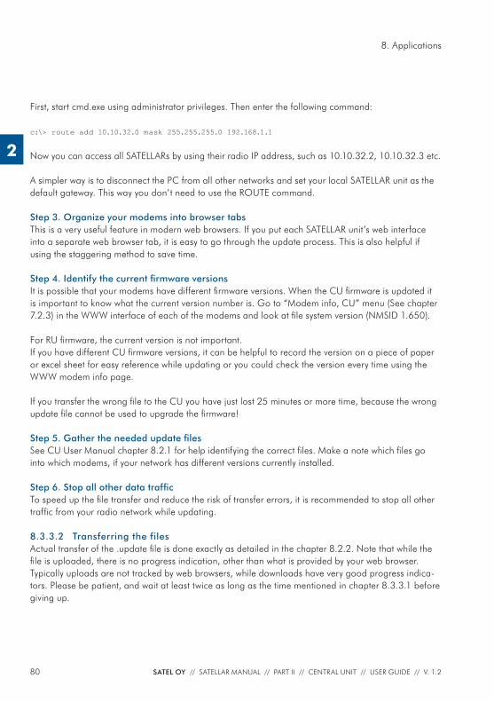
80 SATEL OY // SATELLAR MANUAL // PART II // CENTRAL UNIT // USER GUIDE // V. 1.2
8. Applications
2
First, start cmd.exe using administrator privileges. Then enter the following command:
c:\> route add 10.10.32.0 mask 255.255.255.0 192.168.1.1
Now you can access all SATELLARs by using their radio IP address, such as 10.10.32.2, 10.10.32.3 etc.
A simpler way is to disconnect the PC from all other networks and set your local SATELLAR unit as the default gateway. This way you don’t need to use the ROUTE command.
Step 3. Organize your modems into browser tabsThis is a very useful feature in modern web browsers. If you put each SATELLAR unit’s web interface into a separate web browser tab, it is easy to go through the update process. This is also helpful if using the staggering method to save time.
Step 4. Identify the current fi rmware versionsIt is possible that your modems have different fi rmware versions. When the CU fi rmware is updated it is important to know what the current version number is. Go to “Modem info, CU” menu (See chapter 7.2.3) in the WWW interface of each of the modems and look at fi le system version (NMSID 1.650).
For RU fi rmware, the current version is not important.If you have different CU fi rmware versions, it can be helpful to record the version on a piece of paper or excel sheet for easy reference while updating or you could check the version every time using the WWW modem info page.
If you transfer the wrong fi le to the CU you have just lost 25 minutes or more time, because the wrong update fi le cannot be used to upgrade the fi rmware!
Step 5. Gather the needed update fi lesSee CU User Manual chapter 8.2.1 for help identifying the correct fi les. Make a note which fi les go into which modems, if your network has different versions currently installed.
Step 6. Stop all other data traffi cTo speed up the fi le transfer and reduce the risk of transfer errors, it is recommended to stop all other traffi c from your radio network while updating.
8.3.3.2 Transferring the filesActual transfer of the .update fi le is done exactly as detailed in the chapter 8.2.2. Note that while the fi le is uploaded, there is no progress indication, other than what is provided by your web browser. Typically uploads are not tracked by web browsers, while downloads have very good progress indica-tors. Please be patient, and wait at least twice as long as the time mentioned in chapter 8.3.3.1 before giving up.
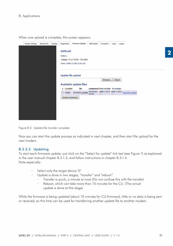
81SATEL OY // SATELLAR MANUAL // PART II // CENTRAL UNIT // USER GUIDE // V. 1.2
8. Applications
2
When one upload is complete, this screen appears:
Figure 8.5 Update fi le transfer complete
Now you can start the update process as indicated in next chapter, and then start fi le upload for the next modem.
8.3.3.3 UpdatingTo start each fi rmware update, just click on the “Select for update” link text (see Figure 1) as explained in the user manual chapter 8.3.1.3, and follow instructions in chapter 8.3.1.4. Note especially:
– Select only the target device ‘0’ – Update is done in two stages, “transfer” and “reboot”.
– Transfer is quick, a minute at most (Do not confuse this with fi le transfer) – Reboot, which can take more than 10 minutes for the CU. (The actual
update is done at this stage)
While the fi rmware is being updated (about 10 minutes for CU fi rmware), little or no data is being sent or received, so this time can be used for transferring another update fi le to another modem.
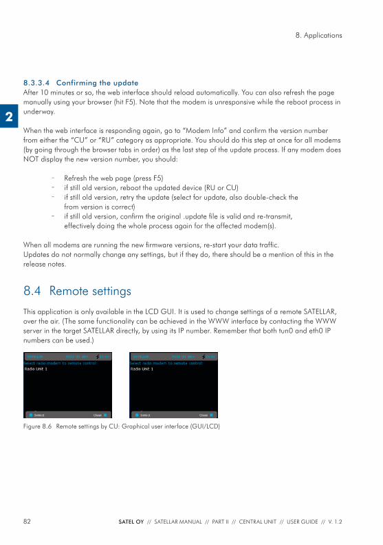
82 SATEL OY // SATELLAR MANUAL // PART II // CENTRAL UNIT // USER GUIDE // V. 1.2
8. Applications
2
8.3.3.4 Confirming the update After 10 minutes or so, the web interface should reload automatically. You can also refresh the page manually using your browser (hit F5). Note that the modem is unresponsive while the reboot process in underway.
When the web interface is responding again, go to “Modem Info” and confi rm the version number from either the “CU” or “RU” category as appropriate. You should do this step at once for all modems (by going through the browser tabs in order) as the last step of the update process. If any modem does NOT display the new version number, you should:
– Refresh the web page (press F5) – if still old version, reboot the updated device (RU or CU) – if still old version, retry the update (select for update, also double-check the
from version is correct) – if still old version, confi rm the original .update fi le is valid and re-transmit,
effectively doing the whole process again for the affected modem(s).
When all modems are running the new fi rmware versions, re-start your data traffi c. Updates do not normally change any settings, but if they do, there should be a mention of this in the release notes.
8.4 Remote settingsThis application is only available in the LCD GUI. It is used to change settings of a remote SATELLAR, over the air. (The same functionality can be achieved in the WWW interface by contacting the WWW server in the target SATELLAR directly, by using its IP number. Remember that both tun0 and eth0 IP numbers can be used.)
Figure 8.6 Remote settings by CU: Graphical user interface (GUI/LCD)
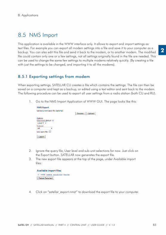
83SATEL OY // SATELLAR MANUAL // PART II // CENTRAL UNIT // USER GUIDE // V. 1.2
8. Applications
2
8.5 NMS ImportThis application is available in the WWW interface only. It allows to export and import settings as text fi les. For example you can export all modem settings into a fi le and save it to your computer as a backup. You can also edit this fi le and send it back to the modem, or to another modem. The modifi ed fi le could contain only one or a few settings, not all settings originally found in the fi le are needed. This can be used to change the same few settings to multiple modems relatively quickly. (By creating a fi le with just the settings to be changed, and importing it to all the modems).
8.5.1 Exporting settings from modem
When exporting settings, SATELLAR CU creates a fi le which contains the settings. The fi le can then be saved on a computer and kept as a backup, or edited using a text editor and sent back to the modem. The following procedure can be used to export all user settings from a radio station (both CU and RU).
1. Go to the NMS Import Application of WWW GUI. The page looks like this:
2. Ignore the query fi le, User level and sub-unit selections for now. Just click on the Export button. SATELLAR now generates the export fi le.
3. The new export fi le appears at the top of the page, under Available import fi les:
4. Click on “satellar_export.nmst” to download the export fi le to your computer.
84 SATEL OY // SATELLAR MANUAL // PART II // CENTRAL UNIT // USER GUIDE // V. 1.2
8. Applications
2
8.5.2 NMS Export advanced features
These optional features are available:
Option Effect
Query fi le If you wish to export only some specifi c settings, create a text fi le containing only the NMSIDs, one per row, and use it as the query fi le. Click Browse to select the fi le and Upload to send it to the modem.
Example query fi le contents:
1.398
1.33
1.80
Use query fi le Mark this checkbox to use the query fi le that was uploaded. The resulting export fi le will only contain the values of the NMSIDs that were specifi ed in the query fi le.
User level Level 1 is the normal level. Sometimes SATEL technical support may request you to export level 5 or 9 settings in case the information is needed to solve a problem. Level 5 or 9 settings cannot be changed.
Sub-unit Choose All to export both RU and CU settings. Sub-unit 0 exports only RU settings and sub-unit 1 exports only CU settings.
Table 8.7 NMS Export advanced features
8.5.3 The export/import file contents
The export fi le is a text fi le in UNIX format. This means that the windows default text editor ‘notepad.exe’, does not correctly split the text into lines, instead all text appears on one long line. The fi le should not be edited with an editor which does not support Unix-style text. We recommend using a better text editor, such as ‘Notepad++’ which is freely available on the net.
The fi le contains a list of NMSIDs, followed by the ‘=’ character and the value assigned to that NMSID. There are also comment rows, which usually give the name of the following NMSID and possibly the list of valid values.
Example 1:#Address (RMAC)
0:1.398=1
The fi rst row is a comment, identifi ed by the ‘#’ character. Everything on comment rows is ignored when importing. This comment tells us that the next NMSID is the address.
The next row begins with a zero, followed by a colon character ‘:’. The zero indicates the sub-unit is the RU (1 would be CU). Next number is the NMSID, which is ‘1.398’. After the equal sign ‘=’ is the value, which is 1. The address of the RU is therefore set to 1.
85SATEL OY // SATELLAR MANUAL // PART II // CENTRAL UNIT // USER GUIDE // V. 1.2
8. Applications
2
Example 2:#Protocol Mode
#0 = Basic-RX Priority, 1 = Basic-TX Priority, 2 = Basic-Repeater, 6 = Packet Routing
0:1.409=6
The two comment rows tell that this is the Protocol Mode setting, and valid choices are 0, 1, 2, or 6. The comment explains what each number means. The actual NMSID row again shows that sub-unit is 0 (RU), the NMSID is ‘1.409’ and the current value is ‘6’.
8.5.4 Managing export files
You can use export fi les as backup to store the settings of devices in your network, so in case you need to replace the hardware, you can just import the saved settings to the new hardware. In this case it is useful to name the export fi les to the name of the radio station, for example.
Remember that the fi le extension must remain as .nmst, otherwise you are free to rename the fi le. Avoid using special characters in the name.
Another way to use export/import fi les is to create a fi le containing all the settings, which are common to all modems in your network. Some such settings are RX and TX frequencies (0:1.256 and 0:1.257), bandwidth, airspeed, encryption keys, network ID, TUN Base Address (1:1.3212) etc. These settings must be the same in each modem for the network to work. If you put all these settings in a single fi le, you can easily import it to all modems, saving time and avoiding errors caused by inputting all the settings by hand.
Another use related to the above is to copy some settings from one modem to another. In this case you should carefully edit the fi le after exporting, removing any settings you do not wish to modify in the target device. For example you might want to create a copy of a modem you have already confi g-ured, except for the Address and IP settings, which should remain as they are. In this case remove the relevant rows from the fi le before importing it to the target modem.Always be careful of typing errors when editing the fi le. If any errors appear in the fi le, the whole import process fails (see next paragraph).
NMS Commands, such as Save User settings, Restore User settings and Reset should NOT be used in an import fi le.
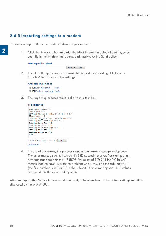
86 SATEL OY // SATELLAR MANUAL // PART II // CENTRAL UNIT // USER GUIDE // V. 1.2
8. Applications
2
8.5.5 Importing settings to a modem
To send an import fi le to the modem follow this procedure:
1. Click the Browse… button under the NMS Import fi le upload heading, select your fi le in the window that opens, and fi nally click the Send button.
2. The fi le will appear under the Available import fi les heading. Click on the
“Use fi le” link to import the settings.
3. The importing process result is shown in a text box.
4. In case of any errors, the process stops and an error message is displayed. The error message will tell which NMS ID caused the error. For example, an error message such as this: “ERROR: Value set of 1.769/-1 for 0.0 failed” means that the NMS ID with the problem was 1.769, and the subunit was 0 (the fi rst number in 0.0 or 1.0 is the subunit). If an error happens, NO values are saved. Fix the error and try again.
After an import, the Refresh button should be used, to fully synchronize the actual settings and those displayed by the WWW GUI.
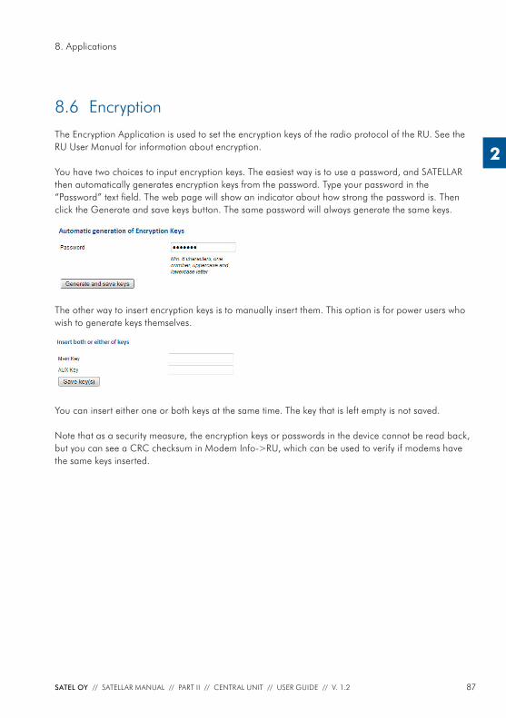
87SATEL OY // SATELLAR MANUAL // PART II // CENTRAL UNIT // USER GUIDE // V. 1.2
8. Applications
2
8.6 EncryptionThe Encryption Application is used to set the encryption keys of the radio protocol of the RU. See the RU User Manual for information about encryption.
You have two choices to input encryption keys. The easiest way is to use a password, and SATELLAR then automatically generates encryption keys from the password. Type your password in the “Password” text fi eld. The web page will show an indicator about how strong the password is. Then click the Generate and save keys button. The same password will always generate the same keys.
The other way to insert encryption keys is to manually insert them. This option is for power users who wish to generate keys themselves.
You can insert either one or both keys at the same time. The key that is left empty is not saved.
Note that as a security measure, the encryption keys or passwords in the device cannot be read back, but you can see a CRC checksum in Modem Info->RU, which can be used to verify if modems have the same keys inserted.
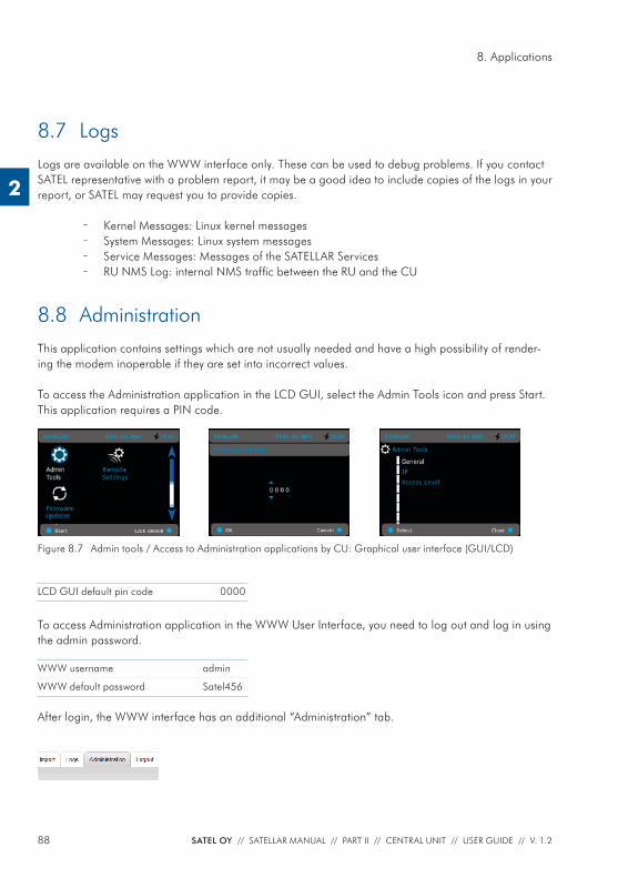
88 SATEL OY // SATELLAR MANUAL // PART II // CENTRAL UNIT // USER GUIDE // V. 1.2
8. Applications
2
8.7 LogsLogs are available on the WWW interface only. These can be used to debug problems. If you contact SATEL representative with a problem report, it may be a good idea to include copies of the logs in your report, or SATEL may request you to provide copies.
– Kernel Messages: Linux kernel messages – System Messages: Linux system messages – Service Messages: Messages of the SATELLAR Services – RU NMS Log: internal NMS traffi c between the RU and the CU
8.8 AdministrationThis application contains settings which are not usually needed and have a high possibility of render-ing the modem inoperable if they are set into incorrect values.
To access the Administration application in the LCD GUI, select the Admin Tools icon and press Start. This application requires a PIN code.
Figure 8.7 Admin tools / Access to Administration applications by CU: Graphical user interface (GUI/LCD)
LCD GUI default pin code 0000
To access Administration application in the WWW User Interface, you need to log out and log in using the admin password.
WWW username admin
WWW default password Satel456
After login, the WWW interface has an additional “Administration” tab.
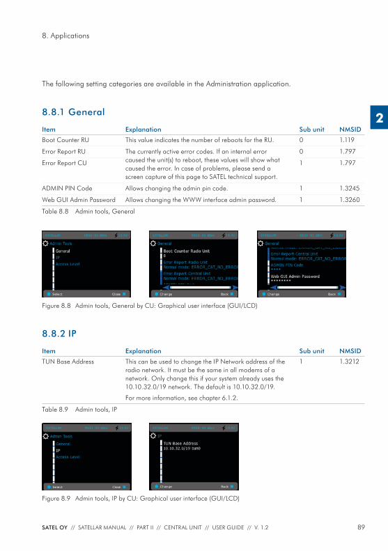
89SATEL OY // SATELLAR MANUAL // PART II // CENTRAL UNIT // USER GUIDE // V. 1.2
8. Applications
2
The following setting categories are available in the Administration application.
8.8.1 General
Item Explanation Sub unit NMSID
Boot Counter RU This value indicates the number of reboots for the RU. 0 1.119
Error Report RU The currently active error codes. If an internal error caused the unit(s) to reboot, these values will show what caused the error. In case of problems, please send a screen capture of this page to SATEL technical support.
0 1.797
Error Report CU 1 1.797
ADMIN PIN Code Allows changing the admin pin code. 1 1.3245
Web GUI Admin Password Allows changing the WWW interface admin password. 1 1.3260
Table 8.8 Admin tools, General
Figure 8.8 Admin tools, General by CU: Graphical user interface (GUI/LCD)
8.8.2 IP
Item Explanation Sub unit NMSID
TUN Base Address This can be used to change the IP Network address of the radio network. It must be the same in all modems of a network. Only change this if your system already uses the 10.10.32.0/19 network. The default is 10.10.32.0/19.
For more information, see chapter 6.1.2.
1 1.3212
Table 8.9 Admin tools, IP
Figure 8.9 Admin tools, IP by CU: Graphical user interface (GUI/LCD)
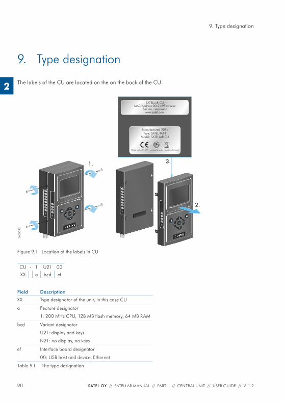
90 SATEL OY // SATELLAR MANUAL // PART II // CENTRAL UNIT // USER GUIDE // V. 1.2
9. Type designation
2
9. Type designation
The labels of the CU are located on the on the back of the CU.
1.
TD
RD
PWR
STAT
RX
TX
CTS
RTS
USB
ETH
PWR
STAT
OK
3.
SATELLAR CUMAC Address:00:21:9F:xx:xx:xx
Ser. no.: xxxx xxxxxwww.satel.com
Manufactured 201xType: SATEL-TA14
Model: SATELLAR CU
Made by SATEL OY - www.satel.com - Made in Finland
Pb
TD
RD
PWR
STAT
RX
TX
CTS
RTS
USB
ETH
PWR
STAT
OK
2.
SA00
025
Figure 9.1 Location of the labels in CU
CU - 1 U21 00
XX a bcd ef
Field Description
XX Type designator of the unit, in this case CU
a Feature designator
1: 200 MHz CPU, 128 MB fl ash memory, 64 MB RAM
bcd Variant designator
U21: display and keys
N21: no display, no keys
ef Interface board designator
00: USB host and device, Ethernet
Table 9.1 The type designation
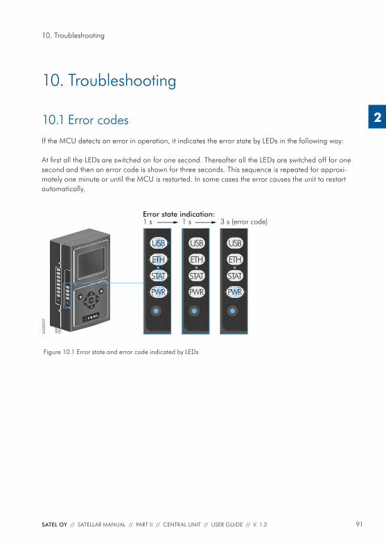
91SATEL OY // SATELLAR MANUAL // PART II // CENTRAL UNIT // USER GUIDE // V. 1.2
10. Troubleshooting
2
10. Troubleshooting
10.1 Error codesIf the MCU detects an error in operation, it indicates the error state by LEDs in the following way:
At fi rst all the LEDs are switched on for one second. Thereafter all the LEDs are switched off for one second and then an error code is shown for three seconds. This sequence is repeated for approxi-mately one minute or until the MCU is restarted. In some cases the error causes the unit to restart automatically.
TD
RD
PWR
STAT
RX
TX
CTS
RTS
USB
ETH
PWR
STAT
OK
Error state indication:1 s
PWR
ETH
USB
1 s
PWR
STAT
ETH
USB
3 s (error code)
PWR
STAT
ETH
USB
STAT
SA00
009
Figure 10.1 Error state and error code indicated by LEDs
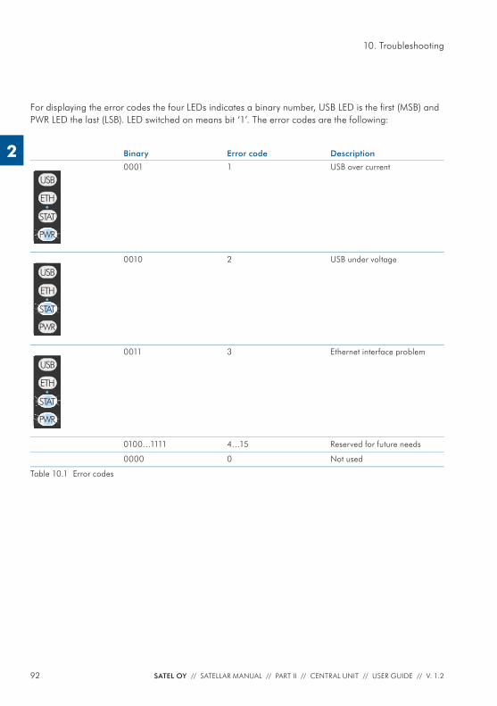
92 SATEL OY // SATELLAR MANUAL // PART II // CENTRAL UNIT // USER GUIDE // V. 1.2
10. Troubleshooting
2
For displaying the error codes the four LEDs indicates a binary number, USB LED is the fi rst (MSB) and PWR LED the last (LSB). LED switched on means bit ‘1’. The error codes are the following:
Binary Error code Description
STAT
ETH
USB
PWR
0001 1 USB over current
ETH
USB
PWR
STAT
0010 2 USB under voltage
ETH
USB
STAT
PWR
0011 3 Ethernet interface problem
0100…1111 4…15 Reserved for future needs
0000 0 Not used
Table 10.1 Error codes
93SATEL OY // SATELLAR MANUAL // PART II // CENTRAL UNIT // USER GUIDE // V. 1.2
11. SATEL open source statements
2
11. SATEL open source statements
11.1 LGPL and GPL softwareThis SATEL product contains open source software (OSS), licensed under LGPLv2, GPLv2, GPLv3 and other licenses.
License details for LGPLv2.1 are available from http://www.gnu.org/licenses/lgpl-2.1.htmlLicense details for GPLv2 are available from http://www.gnu.org/licenses/old-licenses/gpl-2.0.htmlLicense details for GPLv3 are available from http://www.gnu.org/licenses/gpl-3.0.html
ALL OPEN SOURCE SOFTWARE used in this software is distributed WITHOUT ANY WARRANTY and is subject to copyrights of one or more respective authors. For more details, see the GPL and LGPL license texts.
11.2 Written offer for LGPL and GPL source codeWhere such specifi c license terms entitle you to the source code of such software, SATEL will provide upon written request via email and/or traditional paper mail the applicable LGPL and GPL source code fi les via CD-ROM for a nominal fee to cover shipping and media charges as allowed under those respective licenses.
Contact SATEL Technical support for more details: Please visit http://www.satel.com.
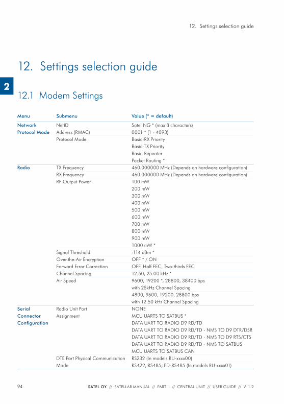
94 SATEL OY // SATELLAR MANUAL // PART II // CENTRAL UNIT // USER GUIDE // V. 1.2
12. Settings selection guide
2
Menu Submenu Value (* = default)
Network Protocol Mode
NetID Satel NG * (max 8 characters)Address (RMAC) 0001 * (1 - 4093)Protocol Mode Basic-RX Priority
Basic-TX PriorityBasic-RepeaterPacket Routing *
Radio TX Frequency 460.000000 MHz (Depends on hardware confi guration)RX Frequency 460.000000 MHz (Depends on hardware confi guration)RF Output Power 100 mW
200 mW300 mW400 mW500 mW600 mW700 mW800 mW900 mW1000 mW *
Signal Threshold -114 dBm *Over.the-Air Encryption OFF * / ONForward Error Correction OFF, Half FEC, Two-thirds FECChannel Spacing 12.50, 25.00 kHz *Air Speed 9600, 19200 *, 28800, 38400 bps
with 25kHz Channel Spacing4800, 9600, 19200, 28800 bps with 12.50 kHz Channel Spacing
Serial Connector Confi guration
Radio Unit Port Assignment
NONEMCU UARTS TO SATBUS *DATA UART TO RADIO D9 RD/TDDATA UART TO RADIO D9 RD/TD - NMS TO D9 DTR/DSRDATA UART TO RADIO D9 RD/TD - NMS TO D9 RTS/CTSDATA UART TO RADIO D9 RD/TD - NMS TO SATBUSMCU UARTS TO SATBUS CAN
DTE Port Physical Communication Mode
RS232 (In models RU-xxxx00)RS422, RS485, FD-RS485 (In models RU-xxxx01)
12.1 Modem Settings
12. Settings selection guide
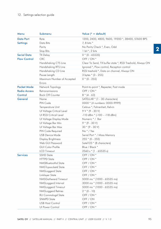
95SATEL OY // SATELLAR MANUAL // PART II // CENTRAL UNIT // USER GUIDE // V. 1.2
12. Settings selection guide
2
Menu Submenu Value (* = default)
Data Port Settings
Rate 1200, 2400, 4800, 9600, 19200 *, 38400, 57600 BPSData Bits 7, 8 bits *Parity No Parity Check *, Even, OddStop Bits 1 bit *, 2 bits
Serial Data Flow Control
TX Delay 0 * (0 - 65535)CRC OFF / ON *Handshaking CTS Line Clear To Send, TX buffer state *, RSSI Treshold, Always ONHandshaking RTS Line Ignored *, Flow control, Reception controlHandshaking CD Line RSSI treshold *, Data on channel, Always ONPause Length 3 bytes * (3 - 255)Maximum Number of Accepted Errors
0 * (0 - 255)
Packet Mode Radio Access Control
Network Topology Point-to-point *, Repeater, Fast modeRetransmissions OFF / ON *Back Off Counter 8 * (4 - 63)
General Name SATELLAR * (1 - 30 characters)PIN Code 0000 * (4 numbers: 0000-9999)Temperature Unit Celsius *, Fahrenheit, KelvinUI Voltage Critical Level 9 V * (9 - 30 V)UI RSSI Critical Level -110 dBm * (-100 - -118 dBm)UI Voltage Display Mode Numeric * / BarUI Voltage Bar Min 9 * (9 - 30 V)UI Voltage Bar Max 30 * (9 - 30 V)PIN Code Required No * / YesUSB Device Mode Serial Port * / Mass MemoryDisplay Brightness 255 * (0 - 255)Web GUI Password Satel123 * (8 characters)GUI Color Profi le Blue / Black *LCD Timeout 2560 s * (1 - 65535 s)
Services SSHD State OFF / ON *HTTPD State OFF / ON *NMSBluetoothd State OFF / ON *NMSTcpsocketd State OFF / ON *NMSLoggerd State OFF / ON *Linklayer State OFF / ON *NMSGathererd Timeout 5000 ms * (1000 - 65535 ms)NMSLoggerd Interval 3000 ms * (1000 - 65535 ms)NMSLoggerd Timeout 5000 ms * (1000 - 65535 ms)NMSLoggerd Retries 2 * (0 - 10)RU Commslogd State OFF / ON *SNMPD State OFF / ONUSB Host Control OFF / ON *UI Power Control OFF / ON *
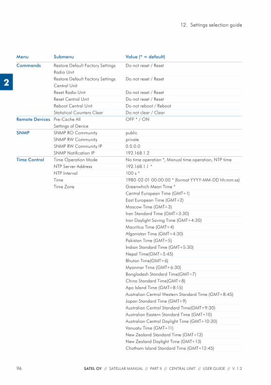
96 SATEL OY // SATELLAR MANUAL // PART II // CENTRAL UNIT // USER GUIDE // V. 1.2
12. Settings selection guide
2
Menu Submenu Value (* = default)
Commands Restore Default Factory Settings Radio Unit
Do not reset / Reset
Restore Default Factory Settings Central Unit
Do not reset / Reset
Reset Radio Unit Do not reset / ResetReset Central Unit Do not reset / ResetReboot Central Unit Do not reboot / RebootStatistical Counters Clear Do not clear / Clear
Remote Devices Pre-Cache All Settings of Device
OFF * / ON
SNMP SNMP RO Community publicSNMP RW Community privateSNMP RW Community IP 0.0.0.0SNMP Notifi cation IP 192.168.1.2
Time Control Time Operation Mode No time operation *, Manual time operation, NTP timeNTP Server Address 192.168.1.1 *NTP Interval 100 s *Time 1980-02-01 00:00:00 * (format YYYY-MM-DD hh:mm:ss)Time Zone Greenwhich Mean Time *
Central European Time (GMT+1)East European Time (GMT+2)Moscow Time (GMT+3)Iran Standard Time (GMT+3:30)Iran Daylight Saving Time (GMT+4:30)Mauritius Time (GMT+4)Afganistan Time (GMT+4:30)Pakistan Time (GMT+5)Indian Standard Time (GMT+5:30)Nepal Time(GMT+5:45)Bhutan Time(GMT+6)Myanmar Time (GMT+6:30)Bangladesh Standard Time(GMT+7)China Standard Time(GMT+8)Apo Island Time (GMT+8:15)Australian Central Western Standard Time (GMT+8:45)Japan Standard Time (GMT+9)Australian Central Standard Time(GMT+9:30)Australian Eastern Standard Time (GMT+10)Australian Central Daylight Time (GMT+10:30)Vanuatu Time (GMT+11)New Zealand Standard Time (GMT+12)New Zealand Daylight Time (GMT+13)Chatham Island Standard Time (GMT+12:45)
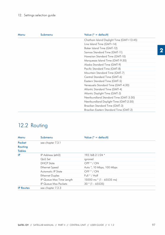
97SATEL OY // SATELLAR MANUAL // PART II // CENTRAL UNIT // USER GUIDE // V. 1.2
12. Settings selection guide
2
Menu Submenu Value (* = default)
Packet Routing Tables
see chapter 7.3.1
IP IP Address (eth0) 192.168.2.1/24 *QoS Set ignoredDHCP State OFF * / ONEthernet Speed Auto *, 10 Mbps, 100 MbpsAutomatic IP State OFF * / ONEthernet Duplex Full * / HalfIP Queue Max Time Length 15000 ms * (1 - 65535 ms)IP Queue Max Packets 30 * (1 - 65535)
IP Routes see chapter 7.3.3
12.2 Routing
Menu Submenu Value (* = default)
Chatham Island Daylight Time (GMT+13:45)Line Island Time (GMT+14)Baker Island Time (GMT-12)Samoa Standard Time (GMT-11)Hawaiian Standard Time (GMT-10)Marquesas Island Time (GMT-9:30)Alaska Standard Time (GMT-9)Pacifi c Standard Time (GMT-8)Mountain Standard Time (GMT-7)Central Standard Time (GMT-6)Eastern Standard Time (GMT-5)Venezuela Standard Time (GMT-4:30)Atlantic Standard Time (GMT-4)Atlantic Daylight Time (GMT-3)Newfoundland Standard Time (GMT-3:30)Newfoundland Daylight Time (GMT-2:30)Brazilian Standard Time (GMT-3)Brazilian Eastern Standard Time (GMT-2)
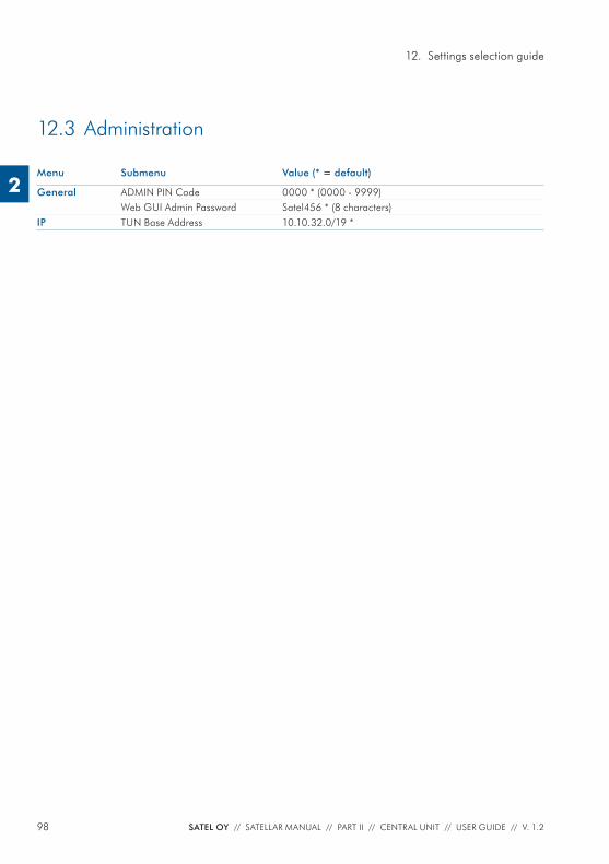
98 SATEL OY // SATELLAR MANUAL // PART II // CENTRAL UNIT // USER GUIDE // V. 1.2
12. Settings selection guide
2
12.3 Administration
Menu Submenu Value (* = default)
General ADMIN PIN Code 0000 * (0000 - 9999)Web GUI Admin Password Satel456 * (8 characters)
IP TUN Base Address 10.10.32.0/19 *


SATEL OyMeriniitynkatu 17, P.O.Box 142
FI-24101 Salo, FinlandTel. +358 2 777 7800
WIRELESS WORLD – LOCAL SOLUTION