sanitary sewers - brantford.ca initiatives design construction manual... · all sanitary sewers and...
TRANSCRIPT

SANITARY SEWERS
DESIGN AND CONSTRUCTION MANUAL
Linear Municipal Infrastructure
V1- October 2017

Sanitary SewersExisting Version New Version New (N); Revised (Rev); Cancelled (C); Reissued (R)
October 2017 N: V1 – Original Final Submission
REVIS ION TRACKING

TABLE OF CONTENTS
12223
45556
66677
77777
888888
9999
101010101010
INTRODUCTION1.0 General Requirements2.0 Other Reference Documents3.0 Industry Standards and Specifications4.0 Other Applicable Acts and Legislations
DESIGN5.0 General6.0 Design Criteria
6.1 Design Flow6.2 Population Equivalents Based on Land Use
7.0 Hydraulic Level of Service7.1 Velocity7.2 Manning's Roughness Coefficient7.3 Pipe Classification7.4 Pipe Grade
8.0 System Layout8.1 General Requirements8.2 New Construction8.3 Existing Infrastructure8.4 Horizontal and Vertical Separation
9.0 Pipe Requirements9.1 General Requirements9.2 Pipe Size9.3 Minimum Pipe Cover9.4 Pipe Material9.5 Pipe Deflection
10.0 Service Laterals10.1 Connection Types10.2 Service Size10.3 Service Location10.4 Minimum Service Cover10.5 Service Material10.6 Service Grade10.7 Cleanout Requirements10.8 Inspection Maintenance Hole10.9 Marking and Plugging Requirements
V1 - October 2017 i

TABLE OF CONTENTS
1010101111111112121212121212
141414
1414141414141515151515
15
11.0 Forcemain Requirements11.1 General Requirements11.2 Pipe Size11.3 Minimum Forcemain Cover11.4 Pipe Material11.5 Pipe Deflection11.6 Forcemain Outlets11.7 Siphons11.8 Corrosion Protection11.9 Tracer Wire11.10 Valves and Valve Chambers11.11 Valve Size and Type11.12 Valve Chamber Requirements11.13 Joints, Fittings, Couplings and Restraint Devices for Forcemains
12.0 Bedding, Cover and Backfill Requirements12.1 Bedding, Embedment and Cover12.2 Backfill
13.0 Maintenance Holes13.1 General Requirements13.2 Type and Size13.3 Spacing13.4 Frame and Cover Requirements13.5 Connections to Maintenance Holes13.6 Adjustment Units13.7 Benching Requirements13.8 Drop Across Maintenance Hole13.9 Drop Structure13.10 Access Requirements
14.0 Joints, Fittings and Restraint Devices
V1 - October 2017 ii

TABLE OF CONTENTS
1617192021212222232424
29303132323637
40
CONSTRUCTIONSPECIAL PROVISIONS - GENERAL15.0 Pipe Requirements16.0 Service Laterals17.0 Cleanouts18.0 Reconnect Existing Sewer Laterals19.0 Pre-Cast Concrete Maintenance Holes20.0 Forcemain Valves and Valve Chambers21.0 Joints, Fittings and Restraint Devices for Forcemains22.0 Corrosion Protection23.0 Tracer Wire24.0 Cleaning and Inspection
TRENCHLESS REHABILITATION25.0 Sewer Preparation and Flow Control26.0 Video Inspection of Sewers27.0 Cured-in-Place Sewer Lining: Design28.0 Cured-in-Place Sewer Lining: Fit and Finish29.0 Lateral Connection Reinstatement and Rehabilitation30.0 Sewer Pipe Joint Sealing and Main Sewers
DESIGN SHEET
V1 - October 2017 iii

L IST OF TABLES
TABLE 1 Sanitary Design Criteria.......................................................TABLE 2 Residential Population Densities..........................................TABLE 3 Industrial, Commercial and Institutional Equivalent Population Densities............................................................TABLE 4 Approved Sanitary Sewer Pipe Materials...............................TABLE 5 Approved Forcemain Pipe Material....................................... TABLE 6 Corrosion Protection........................................................... TABLE 7 Maximum Spacing for Sanitary Maintenance Holes................TABLE 8 Minimum Drop Across Maintenance Holes.............................TABLE 9 CCTV Inspection Form Header Requirement.........................TABLE 10 Sewer Video Text................................................................
56
69
111214152627
V1 - October 2017 iv

SANITARY SEWERS
Introduction
V1 - October 2017 1

2.0 OTHER REFERENCE DOCUMENTS
All sanitary sewers and appurtenances shall be designed and constructed in accordance with the latest versions of this manual as well as other industry standards and best practices, including but not limited to:
• Ontario Provincial Standard Specifications (OPSS) and Ontario Provincial Standard Drawings (OPSD)
• Ministry of Environmental and Climate Change (MOECC) Design Guidelines for Sewage Works
3.0 INDUSTRY STANDARDS AND SPECIFICATIONS
All sanitary sewer and appurtenances materials and components shall comply with the latest versions of all applicable industry standards and specifications for quality management and quality control, including but not limited to:
• The Canadian Standards Association (CSA)
• The American Standard and Testing Materials (ASTM)
INTRODUCTION
1.0 GENERAL REQUIREMENTS
This manual has been prepared to provide the City, consulting engineers, contractors, developers and the general public with a common reference to ensure the consistent application of sanitary sewer design and construction practices in the City.
The information provided is not intended to hinder innovation and is rooted on meeting performance requirements over the lifecycle of the infrastructure. If deviating from the criteria and requirements set out in this manual, the Proponent shall provide justification for the change via a Standard Deviation Form (Appendix G-1 in the General Preface).
The key guiding principles underlying this manual are to:
• Prioritize the health and safety of the public and minimize damage to property.
• Undertake sustainable planning of the Sanitary Sewer System.
• Protect the natural waterbodies in the City, including the Grand River and other minor creeks.
• Meet regulatory and legislative municipal requirements.
• Consider impacts due to climate change.
• Promote and implement shared responsibility between the City and stakeholder.
SANITARY SEWERSINTRODUCTION
V1 - October 2017 2
SANITARY SEWERSINTRODUCTION
4.0 OTHER APPLICABLE ACTS AND LEGISLATIONS
This manual does not supersede, nor replace any legislation governing the design and construction of linear sanitary systems.
The Proponent shall be fully familiar with the latest versions of these legislative requirements when carrying out design and construction of City linear projects such as:
• Municipal Act
• Ontario Water Resources Act
• Environmental Assessment Act
• Environmental Protection Act
V1 - October 2017 3

SANITARY SEWERS
Design
V1 - October 2017 4
5.0 GENERAL
This section outlines the minimum requirements to aid the Consulting Engineer in the design of sanitary sewers and forcemains in the City.
6.0 DESIGN CRITERIA
6.1 Design Flow
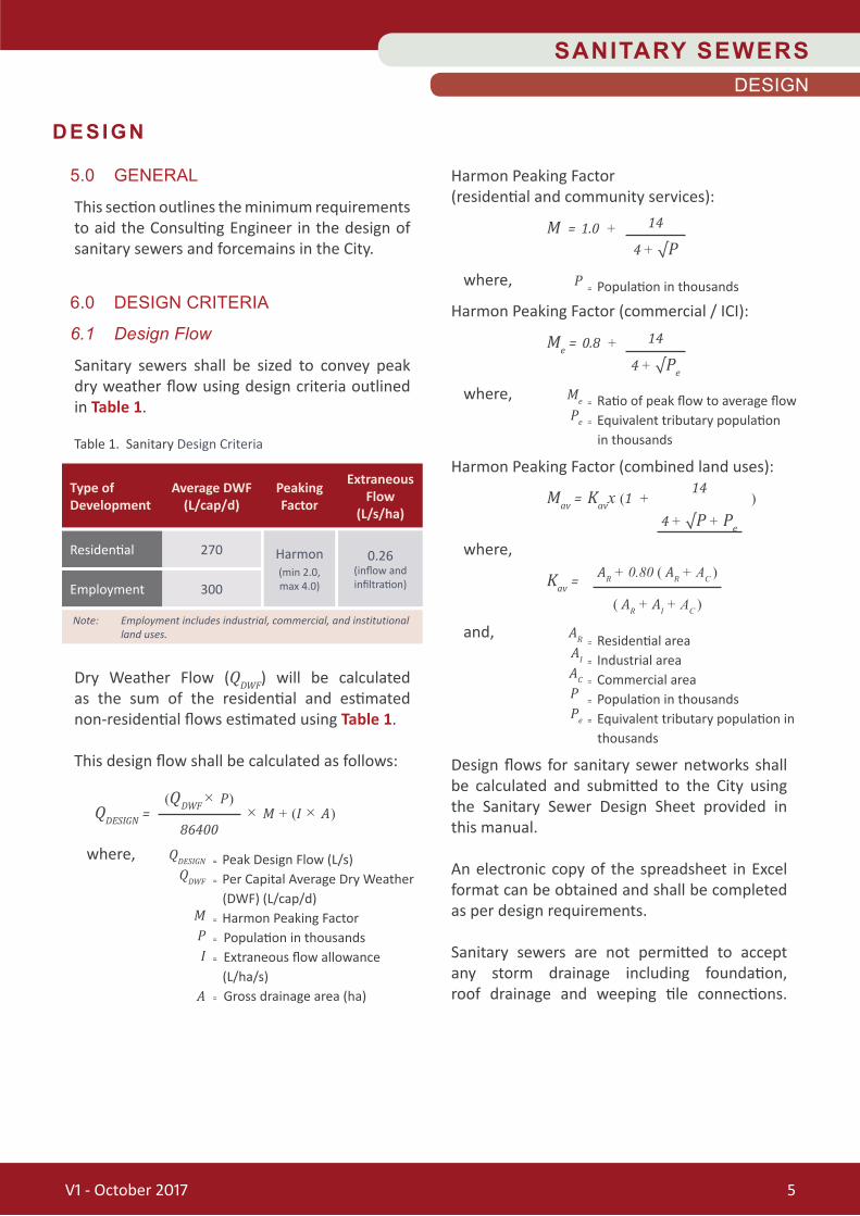
Sanitary sewers shall be sized to convey peak dry weather flow using design criteria outlined in Table 1.
Dry Weather Flow (QDWF) will be calculated as the sum of the residential and estimated non-residential flows estimated using Table 1.
This design flow shall be calculated as follows:
QDESIGN = × M + (I × A)
where, QDESIGN
QDWF
M P I
A
Harmon Peaking Factor(residential and community services):
M = 1.0 +
where, P
Harmon Peaking Factor (commercial / ICI):
Me = 0.8 +
where, Me
Pe
Harmon Peaking Factor (combined land uses):
Mav = Kavx (1 + )
where,
Kav =
and, AR
AI
AC
P Pe
Design flows for sanitary sewer networks shall be calculated and submitted to the City using the Sanitary Sewer Design Sheet provided in this manual.
An electronic copy of the spreadsheet in Excel format can be obtained and shall be completed as per design requirements.
Sanitary sewers are not permitted to accept any storm drainage including foundation, roof drainage and weeping tile connections.
DESIGN
(QDWF × P)
86400
Table 1. Sanitary Design Criteria
Type of Development
Average DWF(L/cap/d)
Peaking Factor
Extraneous Flow
(L/s/ha)
Residential
Employment
270
300
Harmon(min 2.0,max 4.0)
0.26(inflow and infiltration)
Note: Employment includes industrial, commercial, and institutional land uses.
= Peak Design Flow (L/s)= Per Capital Average Dry Weather (DWF) (L/cap/d)= Harmon Peaking Factor= Population in thousands= Extraneous flow allowance (L/ha/s)= Gross drainage area (ha)
14
4 + √P
14
4 + √Pe
= Ratio of peak flow to average flow= Equivalent tributary population in thousands
= Residential area= Industrial area = Commercial area= Population in thousands= Equivalent tributary population in thousands
= Population in thousands
14
AR + 0.80 ( AR + AC )
4 + √P + Pe
( AR + AI + AC )
SANITARY SEWERSDESIGN
V1 - October 2017 5

6.2 Population Equivalents Based on Land Use
The approved population densities based on type of development shall be obtained from Table 2 and Table 3, respectively.
The Consulting Engineer shall confirm population densities, based on existing and future land use, with the City prior to commencing design.
v = Q
A
7.0 HYDRAULIC LEVEL OF SERVICE
7.1 Velocity
The flow velocity shall be determined using the following formula:
where, v = Velocity (m/s) Q = Flow (m3/s) A = Cross Sectional Area of Flow (m2)
Flow velocities for sanitary sewers shall meet the following requirements, in accordance with MOECC Guidelines:
• Minimum average dry weather flow velocity = 0.6 m/s (transport solids and void deposition)
• Maximum full flow velocity = 3.0 m/s
To determine velocities based on actual flow, the Consulting Engineer shall refer to the City’s Sanitary Sewer Design Computation Sheet that includes the roughness coefficient required for Manning’s Equation calculations.
where, Q n A R
S
7.2 Manning'sRoughnessCoefficient
A Manning’s Roughness Coefficient, n, of 0.013 shall be used for all pipe sizes and material.
3.05
2.47
1.60
Population Per Unit (ppu)1
Table 2. Residential Population Densities
Low Density(e.g. single and semi-detached units)
Medium Density(e.g. townhomes, row houses)
High Density(e.g. apartments)
Residential Housing Type
1 City of Brantford, 2014 Development Charges Background Study, Hemson Consulting, March 2014
Population Per Unit (ppu)
90
40
125
4 bed/rooms
Table 3. Industrial, Commercial and Institutional Equivalent Population Densities
Light Commercial(e.g. business parks, shopping malls)
Institutional(e.g. schools, homes for the aged)
Light Industrial(e.g. warehouses, autobody repair)
Hospitals
Land Use Type
Note: ppha = Persons Per Hectare
Equivalent Population
Density (ppha)= Design Flow (m3/s)= Manning's roughness coefficient = Cross Sectional Area of Flow (m2)= Hydraulic Radius (area of flow / wetted perimeter)
= Slope of the Hydraulic Grade Line (m/m)
Q = × A × R⅔ × S½1n
SANITARY SEWERSDESIGN
V1 - October 2017 6

Easements shall be avoided where feasible. Where an easement is deemed to be required, the width for the easement will be reviewed and approved by the City on an individual basis. Trench widths shall be in accordance with OPSD.
Common trenches will be considered when supported by the recommendations of a soils report prepared by a qualified Geotechnical Engineer.
8.2 New Construction
Sanitary sewers shall be in accordance with the City’s Standard Drawings and Typical Cross-sections in this manual. Where this location cannot be provided, a non-standard location must be approved by the City through the Standard Deviation Form
Sanitary sewers shall be terminated with a maintenance hole, at the subdivision limits when the external drainage areas are considered in the design. The design of the upstream terminal maintenance holes shall allow for the future extension of the sanitary sewer.
8.3 Existing Infrastructure
Location of replacement sanitary sewers shall be determined specifically based on the location of existing utilities and other site conditions.
All efforts shall be made to design in accordance with the City’s Standard Drawings and Typical Cross-sections in this manual.
8.4 Horizontal and Vertical Separation
Clearances between watermains, sanitary and storm sewers shall be based on the MOECC Procedure F-6-1: Procedures to Govern the Separation of Sewers and Watermains.
7.3 PipeClassification
The classification of sanitary sewers will be based on the size of the network, the service population and the tributary drainage area.
In the City, sanitary sewers are classified as follows:
— Trunk Sanitary Sewer —
A major conveyance sewer is dedicated to the conveyance of flow from local sewers to the sanitary pumping or treatment facilities.
— Local Sanitary Sewer —
A local sewer is used primarily to collect sanitary flow within a local drainage area.
7.4 Pipe Grade
All sanitary sewers shall be designed with minimum and maximum grade as outlined in MOECC. The minimum pipe grade for sanitary sewers shall be 1% on the first leg of the sewer wherever possible to achieve a self-cleaning velocity of 0.6 m/s.
The remaining system shall be sloped as required to achieve the minimum velocity as stated above at average dry weather flow.
8.0 SYSTEM LAYOUT
8.1 General Requirements
No changes in flow direction shall be permitted without the use of a maintenance hole. All benching and pipe opening alternatives shall be designed in accordance with OPSD. Pipes 1050mm and larger shall not exceed a maximum change in direction of 45°.
SANITARY SEWERSDESIGN
V1 - October 2017 7

9.0 PIPE REQUIREMENTS
9.1 General Requirements
The pipe and appurtenances identified in this manual refer to conventional open cut installation methods.
Where special methods for installation are proposed to be used, (e.g., tunneling, micro-tunneling, jack and bore) drawings and specifications for the installation methods and support for the pipe must be submitted with the overall design. Alternative infrastructure installation methods will be submitted to the City for review prior to design completion.
9.2 Pipe Size
Pipe size shall be determined using Manning’s Formula. The minimum pipe size shall be 250 mm diameter, regardless of the type of land use. A size of 200 mm may be acceptable in the first leg of the sanitary sewer, if required to achieve minimum (self-cleansing) velocity. A decrease in pipe size from upstream to downstream shall be avoided.
9.3 Minimum Pipe Cover
The preferred minimum depth of cover shall be 2.5 m from the finished grade to the top of the pipe. Additional depth may be required in areas where there is potential for conflict with other underground infrastructure. Any deviation to this shall be submitted via a Standard Deviation Form.
Where the cover is less than or equal to 1.5 m, sufficient insulation to prevent freezing of such sections of sanitary sewer shall be provided. Supporting calculations shall be provided to demonstrate pipe deflection will not exceed specified limits due to live loading at shallow burial. Pre-insulated pipe will be considered by the City on a case-by-case basis.
9.4 Pipe Material
All pipe material and fittings shall be in accordance with CSA and ASTM. Both rigid and flexible pipe are permitted in the construction of sanitary sewer systems.
In determining the suitable pipe class to be used, live load, dead load, soil type and trench conditions in accordance with OPSD shall be considered in the calculation.
The pipe manufacturer’s recommendations shall be incorporated into the design.
PVC is the preferred pipe material. Evaluation of other pipe materials must be submitted to the City for review and approval prior to selection of pipe materials. Pipe materials selection shall be supported by site conditions including the geotechnical, hydrogeological and hydraulic investigations.
These materials shall meet the requirements outlined in Table 4.
9.5 PipeDeflection
The deformation gauge, also known as the Mandrel test for flexible pipes, shall be successfully completed prior to the City’s acceptance of the sanitary sewer. The Mandrel test shall be conducted according to OPSS.
Maximum pipe deflection from combined live and dead loading shall not exceed the more stringent of OPSS and the pipe manufacturer’s recommendations.
SANITARY SEWERSDESIGN
V1 - October 2017 8

Table 4. Approved Sanitary Sewer Pipe Materials
Main Size (mm) Joint Type Specification General Comments
≤ 600 mm
≥ 450 mm
Gasketed Bell and Spigot
Gasketed Bell and Spigot
PVC pipe shall have a maximum SDR of 35 and a minimum stiffness of 320 kPa.
Smooth-walled pipe only.
Only manufactured tees shall be used.
N/A
CSA B 182.2
OPSS 1841
CSA A257.2, A257.2
OPSS 1820
Polyvinyl Chloride Pipe (PVC)
Concrete (Reinforced)
AWWA C301 pipe and joints may be considered for concrete pipe deep installations. In areas of high water table, joints shall be diapered and grouted.
10.0 SERVICE LATERALS
10.1 Connection Types
Connections to sanitary sewers shall be made using pre-manufactured tee fittings. Wye fittings shall be considered on a case-by-case basis where tee fittings cannot be achieved.
Cross-connections and sump pump connections to the sanitary sewer shall not be permitted. Sanitary sewer laterals shall not be connected directly to maintenance holes.
10.2 Service Size
Single family, semi-detached dwellings and rowed townhouses in residential areas shall have a minimum 100 mm diameter lateral from the mainline to property line.
SANITARY SEWERSDESIGN
Commercial, industrial and institutional laterals shall be a minimum of 150 mm diameter. Laterals are not permitted to be connected to maintenance holes.
Where the diameter of the lateral connection at the sanitary sewer is greater than or equal to half the diameter of the sanitary sewer, the connection shall be made with a manufactured tee or tee wye connection.
10.3 Service Location
The City’s preferred location of the sanitary lateral is shown in the Typical Residential Lot Plan in Appendix G-3 in the General Preface.
New sanitary service laterals to single family, semi-detached and rowed townhouse dwellings shall be individual service laterals. Shared service laterals shall not be permitted.
Wherever possible, private service connections shall not be connected to trunk sanitary sewers.
V1 - October 2017 9

10.4 Minimum Service Cover
The preferred cover at property lines for all service connections shall be 2.15 m.
10.5 Service Material
PVC pipe shall be used for residential lateral connections. The pipe shall be green in colour and DR 28 shall be used. Laterals larger than 100 mm shall be PVC, DR 35.
10.6 Service Grade
The grade of the sanitary sewer lateral shall range between a minimum and maximum of 2% and 8%, respectively. Connections to mainline sewers consisting or rigid or flexible pipe shall be made at 10 and 2 o’clock (along the top of the pipe) using long sweep elbows.
10.7 Cleanout Requirements
Sanitary cleanouts shall be determined if necessary at the discretion of the City and shall be located 0.15 m within right-of-way from property line.
10.8 Inspection Maintenance Hole
For institutional, commercial and industrial properties an inspection maintenance hole shall be located on the private side of the property line for access to the service lateral. A corresponding maintenance hole shall not be required along the mainline sanitary sewer at each property.
10.9 Marking and Plugging Requirements
Plugged or capped service connections shall be marked by a green painted 38 mm x 89 mm x 1 m at the end cap with adhesive tape labeled “CAUTION SANITARY SEWER”.
The service lateral shall be capped 0.3 m inside of property line.
SANITARY SEWERSDESIGN
V1 - October 2017 10
11.0 FORCEMAIN REQUIREMENTS
11.1 General Requirements
A forcemain is a pressurized pipeline conveying wastewater from a pumping station to a maintenance hole or facility.
Forcemains shall be designed to avoid fouling and plugging and to minimize the generation of hydrogen sulphide.
Forcemains shall be designed to withstand all surge and transient pressures and full vacuum. Transient analyses shall be part of the engineering scope for all forcemains, taking into account the number and timing of the pump cycles to which they will be subjected.
Ideally, local high points or low points shall be avoided.
11.2 Pipe Size
Flow velocities in sanitary forcemains shall be determined using the Hazen-William’s formula:
Q = 0.275 CD 2.63S 0.54
where, Q CDS
Forcemains sizes shall be based on maintaining adequate flow velocities within the following limits:
• Minimum acceptable velocity = 1.0 m/s
• Maximum acceptable velocity = 2.5 m/s
= Design Flow (m3/s)= Hazen Williams Friction Coefficient = Diameter (m)= Slope of the Energy Grade Line (m/m)

11.3 Minimum Forcemain Cover
The preferred minimum depth of cover shall be 1.85 m from the finished grade to the top of the pipe. Additional depth may be required in areas where there is potential for conflict with other underground infrastructure.
Where the preferred minimum specified cover of 1.85 m over the forcemain cannot be achieved, sufficient insulation to prevent freezing. Supporting calculations shall be provided to demonstrate pipe deflection will not exceed specified limits due to live loading.
11.4 Pipe Material
Forcemain pipe and thrust blocks shall be selected to meet maximum operating conditions and transients. Approved forcemain pipe material is outlined in Table 5. Under no circumstances shall the material be coloured blue.
SANITARY SEWERSDESIGN
11.5 PipeDeflection
Maximum pipe deflection from combined live and dead loading shall not exceed the more stringent of OPSS and the pipe manufacturer’s recommendations. Restrained or mechanical joint bends are preferred.
11.6 Forcemain Outlets
The Consulting Engineer shall make provisions for a smooth transition from forcemain pressure flow to gravity sanitary sewer flow.
Forcemains shall discharge to maintenance holes at an invert elevation no greater than 0.6 m above the obvert of the outlet sanitary sewer.
Forcemains shall not be designed to discharge into other forcemains.
Table 5. Approved Forcemain Pipe Material
Main Size (mm) Joint Type Specification General Comments
≤ 400 mm
≤ 400 mm
≤ 400 mm
Gasketed Bell and Spigot
Butt Fusion
Mechanical, Flanged or Tyton
Consulting Engineer shall determine pressure class and rating based on project requirements.
Project Specific basis as determined by design review process.
For use on siphons.
Project specific basis as determined by design review process.
Catholic protection is required.
Pipe:AWWA M23AWWA C900AWWA C905CSA 137.3
AWWA C906
AWWA C104, C105, C110, C111, C115, C150, C151, C153
Fittings:(100 to 300mm)AWWA C907CSA B137.2
(250 to 300mm)AWWA C900CSA B137.3
Polyvinyl Chloride Pipe (PVC)
High Density Polyethylene (HDPE)
Ductile Iron, Hyprotec Coated
V1 - October 2017 11
= Design Flow (m3/s)= Hazen Williams Friction Coefficient = Diameter (m)= Slope of the Energy Grade Line (m/m)

11.7 Siphons
Unlike sanitary sewers, siphons operate under pressure. Siphons shall be installed with at least two pipes.
A multiple barrel system better achieves self-cleansing velocities (minimum 0.9 m/s), manages the potential for gas generation and allows for flexibility in maintenance and operational activities.
Inlet and outlet structures and adequate pipe sizing to allow for cleaning, inspection, flushing activities, flow control and odour control.
11.8 Corrosion Protection
Corrosion protection for forcemains shall in accordance with OPSS and shall be a complete petrolatum coating system or cathodic protection in the form of zinc anodes as follows:
11.9 Tracer Wire
Tracer wire shall be installed on all forcemains.
The wire shall be installed in such a manner as to be able to properly trace the forcemain without loss or deterioration of signal or without the transmitted signal migrating off the tracer wire.
Tracer wire shall be TWU, number eight (8) gauge, stranded, insulated copper wire with 60 mil of black, cross-linked polyethylene (XLPE) insulation specifically manufactured for direct bury applications.
11.10 Valves and Valve Chambers
Valve chambers are required for combination air release / vacuum valves and drain valves on forcemains.
11.11 Valve Size and Type
Combination air release and vacuum valves suitable for sanitary sewer applications shall be located in chambers with vent lines that include a double check valve assembly for flood protection.
All combination air release and vacuum valves shall be provided with isolation valves and drains.
Drain pipe and check valves shall be located in chambers.
Table 6. Corrosion Protection
Buried Metallic Fittings – on flanged surfaces, nuts, bolts, tie rods, clamps, mechanical restraints, valves, sleeves and couplings
Valve Chambers – surface of pipes, valves and appurtenances
Metallic Forcemain – at each metallic component
PVC Forcemain– 1.0 m horizontally from each metallic component
Cathodic Protection
Complete Petrolatum
System
SANITARY SEWERSDESIGN
V1 - October 2017 12
11.12 Valve Chamber Requirements
In order to facilitate operation and maintenance activities, valve chambers shall be in accordance with the Standard Drawings in this manual and shall provide the following:
• Minimum headroom of 2.1 m
• Minimum of 0.5 m and maximum of 0.8 m clearance between the invert of the sanitary sewer and the chamber floor and,
• Minimum of 0.3 m cover above the chamber top slab.
• Minimum of 0.6 m of horizontal clearance on valves and 0.3 m below valves to allow sufficient space for servicing and / or removal when required.
• Valve chamber and lid size shall be selected to adequately accommodate all valves and other ancillary equipment. All concrete valve chambers shall be provided with adequate thrust restraint, approved waterproofing, sealed joints and insulated below the frost depth.
• PVC is not permitted through a valve chamber. Piping at valve chambers shall transition from PVC to ductile iron using couplings located 500 mm from chamber walls.
• Valve chambers located in gravel shoulders shall be provided with a minimum of 1.0 m paved shoulder area on each end starting from the edge of chamber.
11.13 Joints, Fittings, Couplings and Restraint Devices for Forcemains
All joints, fittings, couplings and restraint devices for forcemains shall be in accordance with OPSS and OPSD and shall be compatible with the pipe material and class with which they will be used.
Approved fittings and joints shall be as shown in Table 5.
Joints restraints shall be designed to withstand testing pressure. All joints shall be mechanically restrained as required and thrust blocks shall be used at all tees, bends and valve caps.
All joints shall be mechanically restrained throughout and thrust blocks shall be used at all tees and bends deflecting 11.25 degrees or more.
Required restraint distances shall be determined by the size of pipe, manufacturer and soil conditions and shall be approved by the City.
All restraints shall be designed to a 1.5 Safety Factor and consider worst case scenario soil conditions.
Thrust blocks shall be designed in accordance with OPSD.
SANITARY SEWERSDESIGN
V1 - October 2017 13

12.0 BEDDING, COVER AND BACKFILL REQUIREMENTS
12.1 Bedding, Embedment and Cover
Bedding material shall consist of Granular A. Cover materials shall be native, Granular A or Granular B.
Bedding, cover and embedment materials shall meet OPSS and be placed and compacted in accordance with the standard and associated drawings. Bedding, embedment and cover materials shall be placed for the full width of the trench and mechanically compacted to 98% Standard Proctor Maximum Dry Density (SPMDD) as determined by ASTM.
12.2 Backfill
Backfill shall be considered as starting at 300 mm above the sanitary sewer.
13.0 MAINTENANCE HOLES
13.1 General Requirements
Maintenance holes shall be in accordance with OPSS and OPSD. Maintenance holes shall be pre-benched, located at changes in alignment, grade, pipe size and material, at pipe junctions.
There is a maximum permitted spacing of maintenance holes for sanitary sewers based on the diameter of pipe (refer to Table 7).
Wherever possible, maintenance holes placed in the travel portion of roadways shall not be placed in vehicle wheel paths.
13.2 Type and Size
Maintenance holes shall be precast concrete structures. Under special circumstances, designs using cast-in-place concrete will be considered. Maintenance holes shall be provided with monolithic bases and watertight joints. Grade adjustment units shall be provided where grade adjustments are necessary and shall be in accordance with OPSS.
13.3 Spacing
The maximum spacing distance between each sanitary maintenance hole shall be as outlined in Table 7.
13.4 Frame and Cover Requirements
Frames and covers shall be in accordance with OPSD and OPSS.
Maintenance hole lids shall be watertight if they are to be located within floodplains or stormwater storage areas (i.e., parking lots). The practice of bolting covers will be considered as required.
13.5 Connections to Maintenance Holes
Flexible sanitary sewers shall be connected to maintenance holes using approved adaptors. Connections for rigid pipe shall be grouted in place.
SANITARY SEWERSDESIGN
Table 7. Maximum Spacing for Sanitary Maintenance Hole
Pipe Size (mm) Maximum Spacing (m)
100
150
As approved by the City
300 to 675
750 to 1200
Greater than 1200
V1 - October 2017 14
13.6 Adjustment Units
Maintenance holes should be designed to include precast concrete adjustment units and shall be in accordance with OPSD.
13.7 Benching Requirements
Maintenance holes shall be pre-benched. Pipe opening alternatives shall be designed in accordance with OPSD.
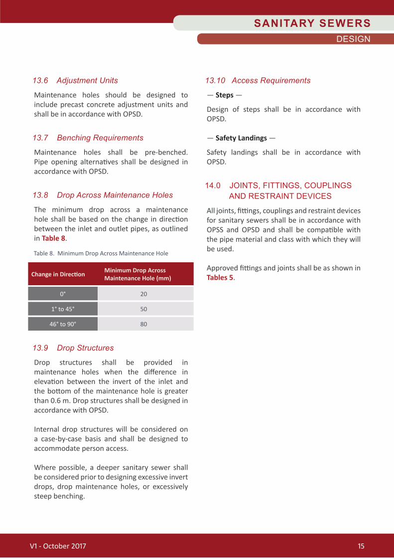
13.8 Drop Across Maintenance Holes
The minimum drop across a maintenance hole shall be based on the change in direction between the inlet and outlet pipes, as outlined in Table 8.
13.9 Drop Structures
Drop structures shall be provided in maintenance holes when the difference in elevation between the invert of the inlet and the bottom of the maintenance hole is greater than 0.6 m. Drop structures shall be designed in accordance with OPSD.
Internal drop structures will be considered on a case-by-case basis and shall be designed to accommodate person access.
Where possible, a deeper sanitary sewer shall be considered prior to designing excessive invert drops, drop maintenance holes, or excessively steep benching.
13.10 Access Requirements
— Steps —
Design of steps shall be in accordance with OPSD.
— Safety Landings —
Safety landings shall be in accordance with OPSD.
14.0 JOINTS, FITTINGS, COUPLINGS AND RESTRAINT DEVICES
All joints, fittings, couplings and restraint devices for sanitary sewers shall be in accordance with OPSS and OPSD and shall be compatible with the pipe material and class with which they will be used.
Approved fittings and joints shall be as shown in Tables 5.
SANITARY SEWERSDESIGN
Table 8. Minimum Drop Across Maintenance Hole
Change in Direction Minimum Drop Across Maintenance Hole (mm)
0°
1° to 45°
46° to 90°
20
50
80
V1 - October 2017 15
SANITARY SEWERS
Construction
V1 - October 2017 16

SANITARY SEWERSCONSTRUCTION
Where the minimum specified cover cannot be achieved, sufficient insulation to prevent freezing of such sections of sanitary sewer shall be provided.
— Maximum Lengths of Open Trench —
The maximum length of open trench when laying sanitary sewer shall be 90 m or the distance necessary to accommodate the amount of pipe installed in a single day, whichever is smaller.
The distance is the collective length at any location including open excavation, pipe length and appurtenant construction and backfill, which has not been completed.
The City standard practice is for trenches to be backfilled at the end of each working day to be evaluated on a case by case basis
— Pipe Laying and Jointing —
Pipe laying and jointing shall be completed in accordance with OPSS.
Proper equipment implements, tools and facilities shall be provided and used. All materials shall be lowered into the trench in accordance with manufacturer’s specification.
Maximum pipe deflection from combined live and dead loading shall not exceed the more stringent of OPSS and the pipe manufacturer’s recommendations. For forcemains, restrained or mechanical joint bends are preferred.
— Cutting of Pipe —
The pipe shall be cut in conformance pipe manufacturer’s recommendations.
15.0 PIPE REQUIREMENTS
15.1 General
This section is in accordance with the provisions of OPSS. The pipe size, type and class shall be as specified. Fittings shall be suitable for and compatible with the pipe material and class with which they are used.
15.2 Materials Requirements
All pipe material and fittings shall be in accordance with CSA and OPSS. Both rigid and flexible pipe are permitted in the construction of sanitary sewer systems.
In determining the suitable pipe class to be used, live load, dead load, soil type and trench conditions shall be in accordance with OPSD.
The pipe manufacturer’s recommendations shall be incorporated.
These materials shall meet the requirements outlined in Table 4 and Table 5.
15.3 Execution
— Excavations —
All excavations shall be done in accordance with the Occupational Health and Safety Act and Regulations for Construction Projects, Revised Statutes of Ontario, 1990 Chapter 1 as amended, most recent Ontario Regulation.
— Minimum Pipe Cover —
The minimum depth of cover for a sanitary sewer shall be 2.5 m and for a forcemain shall be 1.85 m from the finished grade to the top of the pipe. Additional depth may be required in areas where there is potential for conflict with other underground infrastructure.
CONSTRUCTIONSPECIAL PROVIS IONS — CONTRACT
V1 - October 2017 17

15.3 Execution (cont'd)
— Bedding, Embedment and Cover —
Bedding material shall consist of Granular A. Cover material shall be native, Granular A or Granular B.
Bedding, cover and embedment materials shall meet OPSS and be placed and compacted in accordance with the standard and associated drawings.
Bedding, embedment and cover materials shall be placed for the full width of the trench and mechanically compacted to 98% SPMDD, as determined by ASTM.
— Backfill —
Backfill shall be considered as starting at 300 mm above the sanitary sewer. All materials below this point shall be considered as bedding.
Backfill for structures such as maintenance holes and valve chambers shall start at the sub-grade for the structure and will be brought up simultaneously and equally on all sides of the structure, as specified in OPSS.
All backfill material shall be placed and compacted according to OPSS. All backfill materials shall be compacted to 98% SPMDD, in accordance with ASTM.
— Horizontal and Vertical Separation —
Clearances between watermains, sanitary and storm sewers shall be in accordance with the Contract Drawings and MOECC Procedure F-6-1: Procedures to Govern the Separation of Sewers and Watermains.
— Support of Sanitary Seweror Sanitary Sewer Lateral —
At any point where a sanitary sewer or sanitary sewer lateral crosses below any existing watermain, sanitary or storm sewer or utility, the Contractor may be required to install temporary shoring. Any shoring shall be designed and stamped by a Professional Engineer.
— Maintaining Sewer Flows —
The Contractor shall ensure that all sanitary sewer flows are maintained throughout the construction activity. At the end of each working day or as required, the new installations shall be reconnected to the existing sanitary sewers.
The Contractor shall take all reasonable precautions to eliminate discharge to the natural environment.
— Bulkheads —
The sanitary sewers under construction shall be bulkheaded, as required, in such a manner as to prevent infiltration and flushing water from entering the sanitary sewer system. Installation of required bulkheads and their subsequent removal upon completion of work shall be at the Contractor’s expense.
SANITARY SEWERSCONSTRUCTION
V1 - October 2017 18
SANITARY SEWERSCONSTRUCTION
15.5 Basis for Payment
The unit bid price shall include all labour, equipment and materials to supply and install pipe, excavation, disposal of surplus materials, bedding, backfill, compaction, joints, fittings, couplings, restraints tracer wire, local dewatering and support of all utilities.
16.0 SERVICE LATERALS
16.1 General
This section is in accordance with the provisions of OPSS. The service lateral size, type and class shall be as specified.
Fittings shall be suitable for and compatible with the pipe material and class with which they are used. Single family, semi-detached dwellings and rowed townhouses in residential areas shall have a preferred minimum size of 100 mm in diameter.
Commercial, industrial and institutional laterals shall have a preferred minimum size of 150 mm in diameter.
The Consulting Engineer shall confirm the location and depth, at the property limit, of all existing sanitary laterals prior to placing the pre-manufactured tee on the proposed sanitary sewer.
16.2 Materials Requirements
PVC pipe is preferred for residential lateral connections. Service connections to the main line sanitary sewer shall be at a maximum of 45° from the horizontal. The pipe shall be green in colour and SDR 28 shall be used.
15.3 Execution (cont'd)
— Dewatering of Excavations —
Dewatering for excavations for construction shall be in accordance with Ontario Water Resources Act – Ontario Regulation 387/04
• More than 50,000 L/day requires registrations
• More than 400,000 L/day requires a Permit to Take Water
Any water encountered within the trench must be pumped to an approved location. This water must be metered, by a Contractor supplied meter, which has been approved for use by the City.
The Contractor must ensure compliance with the City of Brantford, Chapter 281, Sewer System – Regulation – Use (Sewer Use By-law).
— Special Pipe and Material Installation Methods —
Where special methods for installation are proposed to be used, (e.g. tunneling, microtunneling, jack and bore) drawings and specifications must be submitted with the overall design.
— Cleaning, Testing and Video Inspection —
The sanitary sewers shall be cleaned, tested and video inspected in accordance with City standards.
15.4 Measurement for Payment
Measurement for sanitary sewer installation shall be by length of pipe in linear metres by installation method and size.
V1 - October 2017 19

16.3 Execution
New sanitary service laterals to single family, semi-detached and rowed townhouse dwellings shall be individual service laterals.
Shared service laterals shall not be permitted. Wherever possible, private service connections shall not be connected to trunk sanitary sewers. It is preferred for laterals not to be connected to maintenance holes.
The preferred cover at property lines for all service connections shall be 2.15 m.
The grade of the sanitary lateral shall range between a minimum and maximum of 2% and 8%, respectively. Connections to sanitary sewers shall be made using pre-manufactured tee fittings. Wye fittings shall be considered on a case-by-case basis where tee fittings cannot be achieved.
Cross-connections and sump pump connections to the sanitary sewer shall not be permitted.
Connections to mainline sanitary sewers consisting of rigid or flexible pipe shall be made at 10 and 2 o’clock (along the top of the pipe) using long sweep elbows.
16.4 Measurement for Payment
Measurement for payment shall be by length of service pipe in linear metres.
16.5 Basis for Payment
The unit bid price shall include all labour, equipment and materials to supply and install service laterals, including cleanouts, caps, excavation, disposal of surplus materials, bedding, backfill, compaction, joints, fittings and where necessary, local dewatering and support of all utilities.
17.0 CLEANOUTS
17.1 General Requirements
Sanitary cleanouts shall be determined necessary at the discretion of the City and located 0.15 m within ROW from property line.
17.2 Materials Requirements
Cleanout units shall consist of PVC class SDR 28.
17.3 Execution
Cleanout units shall be delivered complete of all components such as cap, stem, tee, reducers and couplings.
Cleanouts installed within paved areas shall have caps consisting of flat metal plates with no protruding bolts or nuts and shall be installed flush with the surrounding asphalt or concrete surface. In all other areas caps shall be placed approximately 50 mm below the ground surface.
17.4 Measurement for Payment
Measurement for payment shall be for each cleanout.
17.5 Basis for Payment
The unit bid price shall include labour, equipment and materials to supply and install the cleanouts.
SANITARY SEWERSCONSTRUCTION
V1 - October 2017 20

SANITARY SEWERSCONSTRUCTION
18.0 RECONNECT EXISTING SEWER LATERALS
18.1 General Requirements
This section is in accordance with the provisions of OPSS.
18.2 Materials Requirements
N/A
18.3 Execution
To connect new laterals to the existing system, jointing procedures shall be in accordance with OPSS. A watertight connection to the existing lateral is to be made with an approved adapter.
18.4 Measurement for Payment
Measurement for payment under this item shall be for each lateral reconnected.
18.5 Basis for Payment
The unit price bid for this item shall include labour equipment and materials to supply and install the connection.
19.0 PRE-CAST CONCRETE MAINTENANCE HOLES
19.1 General Requirements
This section is in accordance with the provisions of OPSS.
19.2 Materials Requirements
Precast maintenance hole materials shall be in accordance with OPSS.
19.3 Execution
Installation of the precast maintenance hole shall be in accordance with OPSS. A minimum clearance of 500 mm shall be provided between the concrete structure and the trench wall to facilitate proper manual compaction of the Granular A.
Upon completion of construction, the interior of the sanitary sewers, maintenance holes and other access points shall be cleaned thoroughly to remove all debris. Debris and other material removed shall be prevented from passing downstream to receiving sewers or watercourses.
The sanitary sewers and maintenance holes shall be maintained in a clean and serviceable condition until assumption by the City. The maintenance holes shall be cleaned, tested and video inspected.
19.4 Measurement for Payment
Measurement for this unit price bid shall be per maintenance hole installed based on size and depth.
19.5 Basis for Payment
The unit price bid for this item shall include the supply and install of the maintenance hole, including excavation, disposal of surplus materials, bedding, backfill, compaction, local dewatering and support of all utilities.
V1 - October 2017 21
SANITARY SEWERSCONSTRUCTION
21.0 JOINTS, FITTINGS AND RESTRAINT DEVICES FOR FORCEMAINS
21.1 General Requirements
This section is in accordance with the provisions of OPSS. All connections, caps and bends shall be restrained by concrete blocking or restrained joints.
Concrete for thrust blocks shall be placed against undisturbed ground. Joints and couplings shall remain free from concrete. Joints and fittings shall be in accordance with OPSS.
21.2 Materials Requirements
Fittings shall be suitable for and compatible with the pipe material and class with which they will be used and as outlined in Table 5. All concrete pressure pipe will be diapered using Type 50 Cement.
21.3 Execution
Adequate restraints for forcemains shall be provided to withstand the testing pressure. All restraints shall be designed to a 1.5 Safety Factor and consider worst case scenario soil conditions. Refer to Forcemain Design section for acceptable restraint distance requirements. Thrust blocks shall be designed in accordance with OPSD.
21.4 Measurement for Payment
N/A
21.5 Basis for Payment
No separate payment shall be made to meet the requirements of this section. Costs are to be included as part of the appropriate pipe.
20.0 FORCEMAIN VALVES AND VALVE CHAMBERS
20.1 General Requirements
This section is in accordance with the provisions of OPSS. Only licensed City operators can operate valves.
They shall provide a minimum two (2) working days’ notice to coordinate any required shut down and mobilize to site.
20.2 Materials Requirements
All valves and valve chamber materials shall be in accordance with OPSS and OPSD.
20.3 Execution
Valve chambers located in gravel shoulders shall be provided with a minimum of 1.0 m paved shoulder area on each end starting from the edge of chamber.
20.4 Measurement for Payment
Measurement for this unit price bid shall be per chamber installed based on size and depth.
20.5 Basis for Payment
The unit bid price shall include all labour, equipment and materials to supply and install valve chamber, valves, appurtenances, pipe and fittings through the chambers including excavation, disposal of surplus materials, bedding, backfill, compaction and where necessary, local dewatering and support of all utilities.
22V1 - October 2017 22

22.0 CORROSION PROTECTION
22.1 General Requirements
This section shall be in accordance with the provisions of OPSS.
22.2 Materials Requirements
— Complete Petrolatum Coating System —
All material for complete petrolatum coating systems shall be in accordance with OPSS and AWWA.
— Cathodic Protection —
Zinc anodes shall be 11 kg Packaged Zinc Anode. This anode shall be manufactured using a High Purity Zinc 99.99% pure in accordance with ASTM.
The anode must have a metallic core, or fusion bonded sleeve and have a depolarizing gypsum base material surrounding the anode.
An insulated copper (AWG 10-14) wire 3.0 metres in length shall be brazed to the end of the core wire.
The following are specified anode sizing:
• Valves and Hydrants — 11 kg
• Watermain Fittings (if PVC watermain is used) — 11 kg
• Water Services 38 mm and 50 mm — 11 kg
• Water Services under 38 mm — 5.5 kg
22.3 Execution
22.4 Measurement for Payment
N/A
22.5 Basis for Payment
No separate payment shall be made to meet the requirements of this section. Costs are to be included as part of the appropriate tender item.
SANITARY SEWERSCONSTRUCTION
23
Buried Metallic Fittings – on flanged surfaces, nuts, bolts, tie rods, clamps, mechanical restraints, valves, sleeves and couplings
Valve Chambers – surface of pipes, valves and appurtenances
Metallic Forcemain – at each metallic component
PVC Forcemain– 1.0 m horizontally from each metallic component
Cathodic Protection
Complete Petrolatum
System
V1 - October 2017 23

No breaks or cuts in the tracer wire or tracer wire insulation shall be permitted. Except for approved spliced in connections, tracer wire shall be continuous and without splices from test box to test box.
For directional drilling, augering or boring installations, four #8 tracer wires shall be installed with the pipe and connected to the tracer wire at both ends, or cadwelded to the existing iron pipe at both ends.
23.4 Measurement for Payment
N/A
23.5 Basis for Payment
No separate payment shall be made to meet the requirements of this section. Costs are to be included as part of the appropriate pipe.
24.0 CLEANING AND INSPECTION
24.1 General Requirements
During construction the Contractor will be responsible for the flushing and cleaning of all new and existing sewers. The Contractor is required to provide sanitary sewer videos for all new and existing downstream sewers after construction is completed within one leg downstream of the construction limits.
Flushing and cleaning of sewers must be performed by a qualified contractor. Any debris in the sewers must be trapped and removed at downstream maintenance holes.
The videos shall be scheduled to be completed immediately following the base asphalt paving. Work must be performed by a qualified Contractor. The purpose for a sanitary sewer video inspection is to show that the new, existing and downstream sewers are clean, undamaged from the construction and are operating properly.
23.0 TRACER WIRE
23.1 General
The provisions of the latest revisions of OPSS. Tracer wire shall be installed on forcemains.
The wire shall be installed to properly trace the forcemain without loss or deterioration of signal or without the transmitted signal migrating off the tracer wire.
23.2 Materials Requirements
Tracer wire shall be TWU, number eight (8) gauge, stranded, insulated copper wire with 60 mil of black, cross-linked polyethylene (XLPE) insulation specifically manufactured for direct burial applications.
All tracer wire welds onto pipe shall be completely sealed with the use of a Royston Handy Cap IP lubricated assemblies or approved equivalent. In all cases, the pipe is to be properly cleaned and material applications shall be according to the manufacturer’s instructions.
All spliced or repaired wire connections in the tracer wire system shall be made using a Dryconn Waterproof Connector or a Model Number 454, Catalogue Number 30-454, Wing Nut Wire Connector (for two to four #8 wires), or approved equivalent and made waterproof using an approved buried service wire closure. The buried service wire closure shall be either a Klik-It II Number C8816 Buried Service Wire Closure or a Raychem GHFC-2-90 H-Frame Gel Closure or approved equivalent.
23.3 Execution
Tracer wire shall be laid flat and securely affixed to the pipe at 3.0 metre intervals. The wire shall be protected from damage during the execution of the works.
SANITARY SEWERSCONSTRUCTION
V1 - October 2017 24

24.2 Materials Requirements
N/A
24.3 Execution
— Cleaning —
Flushing and cleaning of sewers must be performed by a qualified contractor.
— Inspection —
All work shall be in accordance with the below provisions and PACP® / CSA PLUS 4012 Pipeline Assessment and Certification Program (PACP®) Canadian Edition. CSA Standards, working with NASSCO, Inc. (National Association of Sewer Service Companies), have created the Canadian Edition of the Pipeline Assessment and Certification Program (PACP®), available through certified trainers across Canada. The Canadian Edition includes the NASSCO PACP® manual and CSA’s plus 4012 Visual Sewer Pipe Inspection Technical Guide.
These resources provide industry with the ability to accurately model infrastructure assets using standard tools and methodology common across Canada and the United States.
The CSA plus 4012 Visual Sewer Inspection Technical Guide introduces the concept of distress and defect “severity” and “extent”. This provides a framework to organize distress and defect codes into “primary failure modes” and maps the PACP® codes into the framework – a significant addition to accepted practice in Canada.
All inspectors shall have successfully completed the PACP® / CSA PLUS 4012 Pipeline assessment and Certification Program (PACP®) Canadian Edition.
The Contractor will be required to inspect and record the sanitary sewer pipe and assess the condition of the pipe according to coding standards specified in the NASSCO PACP® manual and CSA’s plus 4012 Visual Sewer Pipe Inspection Technical Guide including but not limited to:
• Structural condition of pipe walls. Length, size, material type and depth of each pipe (all depths shall be referenced from the top of the maintenance hole frame to the invert of the pipe being inspected.
• Any blockage or obstruction located within the pipe.
• Condition of pipe joints and lateral connections.
• Any change in pipe diameter or pipe materials encountered in any section between two maintenance holes.
• Report on grade of pipe as to whether it is uniform or whether there appears to be sectional settlement or grade changes.
• Infiltration.
• Explanation for water level fluctuations.
• Location and condition of connection of sanitary sewer laterals, including pan and tilt of all junctions / connections unless otherwise specified by the City.
• Still capture pictures shall be taken of all significant structural and/or operational deficiencies.
SANITARY SEWERSCONSTRUCTION
V1 - October 2017 25
24.3 Execution (cont'd)
— Equipment —
CCTV equipment shall include video cameras, a video monitor cable, power sources and all equipment necessary to perform a CCTV inspection.
The cameras shall have Pan-and-Tilt capabilities, a minimum of 360 x 270 degree rotation and provide a minimum of 460 lines of resolution. The focal distance shall be adjustable through a range from 25 mm (1 inch) to infinity.
During CCTV inspection, lighting intensity shall be adjusted to minimize glare. Lighting and picture quality shall be adjusted to provide a clear, in-focus picture of the entire periphery of the pipeline for all conditions encountered.
All camera systems shall be able to navigate around minor objects, roots and debris. The system used to move the camera through the pipe shall not obstruct the camera’s view or interfere with proper documentation of the sanitary sewer conditions.
The camera cable shall be retracted to remove slack and to ensure an accurate distance reading. The distance shall be measured between the exit of the start maintenance hole and the entrance of the finish maintenance hole for a true measurement of the length of the pipe segment, as required by PACP. It shall be recorded in standard units and the video display readout shall display units to one-tenth of a metre.
The cable footage-counter shall be accurate to plus or minus 2 metres per 1,000 metres. Video inspection and reporting shall be submitted in a NASSCO- compatible format. The camera lens shall be kept clear of condensation and debris during the CCTV inspection.
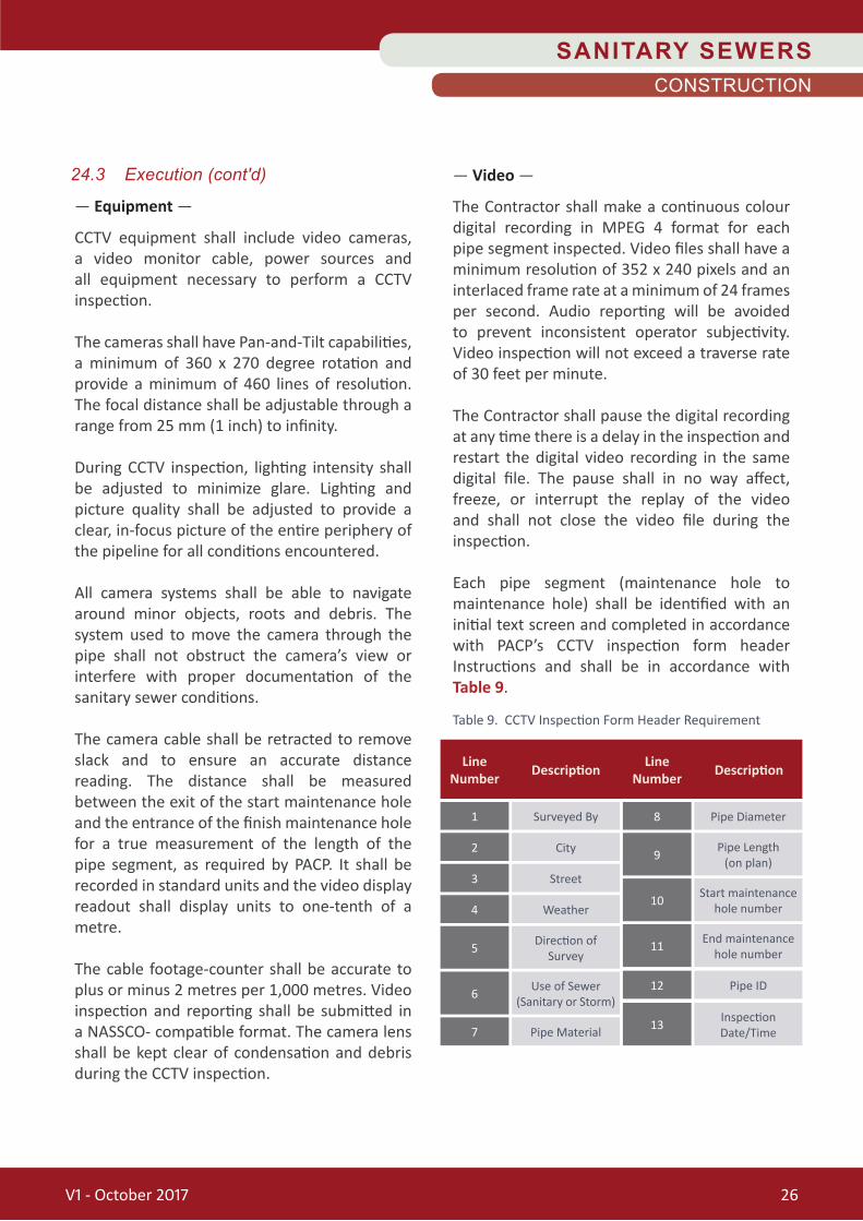
— Video —
The Contractor shall make a continuous colour digital recording in MPEG 4 format for each pipe segment inspected. Video files shall have a minimum resolution of 352 x 240 pixels and an interlaced frame rate at a minimum of 24 frames per second. Audio reporting will be avoided to prevent inconsistent operator subjectivity. Video inspection will not exceed a traverse rate of 30 feet per minute.
The Contractor shall pause the digital recording at any time there is a delay in the inspection and restart the digital video recording in the same digital file. The pause shall in no way affect, freeze, or interrupt the replay of the video and shall not close the video file during the inspection.
Each pipe segment (maintenance hole to maintenance hole) shall be identified with an initial text screen and completed in accordance with PACP’s CCTV inspection form header Instructions and shall be in accordance with Table 9.
V1 - October 2017 26
Table 9. CCTV Inspection Form Header Requirement
Line Number
Line NumberDescription Description
1
3
7
2
4
5
9
10
11
13
6
8
12
Surveyed By
Street
Pipe Material
City
Weather
Direction of Survey
Pipe Length(on plan)
Start maintenance hole number
End maintenance hole number
InspectionDate/Time
Use of Sewer(Sanitary or Storm)
Pipe Diameter
Pipe ID
SANITARY SEWERSCONSTRUCTION

24.3 Execution (cont'd)
This data must completely match the data entered in the database header information. The initial text screen shall appear no more than 15 seconds at the beginning of the video footage and shall appear before the 360 degree pan of the starting maintenance hole.
During the CCTV inspection, the video shall show the text in Table 10 at all times.
During the CCTV inspection, the camera shall stop at all defects and significant observations to ensure a clear and focused view of the pipe condition and shall rotate the camera head at the defect to allow for adequate evaluation at a later time.
All defects and significant observations shall include a text overlay of the recorded observation. The video recording shall include on-screen observation text for every observation recorded in the database.
The naming of the video file shall be as per GIS ID numbers as supplied by the City.
— Photographs —
Digital photographs in JPEG format shall be made of all recorded defect observations. These photographs will be computer generated with the use of the inspection reporting system software. JPEG images shall be captured at a minimum resolution of 640 x 480 pixels. At a minimum, all photographs shall be named consisting of the following descriptions:
“FROM MAINTENANCE HOLE NUMBER”, “TO MAINTENANCE HOLE NUMBER”, eight digit inspection date and the defect location (measurement) along the pipe.
It is the Contractor's discretion as to additional data information that may be needed in the naming of the files to make each file unique within the file naming constraints of their inspection software.
A minimum of two (2) photographs of each defect shall be taken, one with a perspective view and one with a close-up view.
— Additional Inspection Procedures —
A full 360 degree pan of all maintenance holes is required. This video footage shall occur at the beginning of each pipe segment survey inspection from the bottom of the maintenance hole panning up the maintenance hole shaft.
The Contractor shall cover the maintenance hole opening to prevent too much light from entering the structure and to ensure a clear and focused view of the maintenance hole interior. In instances when the maintenance hole is the terminating maintenance hole, then the pan shall occur at the end of the pipe segment survey inspection.
Video footage shall be taken centered on the pipe with the water level running horizontally.
SANITARY SEWERSCONSTRUCTION
V1 - October 2017 27
Table 10. Sewer Video Text
Line Number
Line NumberDescription Description
1
2
53
4City
Street Start / End Maintenance hole
NumberInspection date, time, running total
Pipe ID

24.3 Execution (cont'd)
— Additional Inspection Procedures (cont'd) —
The camera shall run along the invert of the pipe and not at its side, unless it is passing a point obstacle. If extended driving on the side of the pipe is required, then either the pipe needs a more thorough cleaning or an observation should be noted from the PACP codes describing the nature of the obstacle.
Obstructions may be encountered during the course of the CCTV inspection that prevents the travel of the camera. In instances when obstructions are not passable, the Contractor shall withdraw the equipment and begin a CCTV inspection from the opposite end of the sanitary sewer reach.
— Inspection Record Submission —
Contractor shall include all versions of the inspections in the database. The Contractor shall submit the following deliverables once all video inspections are complete:
a. One (1) copy of the sewer video must be submitted electronically in MPEG Format.
b. Each section videoed shall have a separate video report. Video report shall be in PDF format on the disc.
c. The Contractor shall also submit one (1) hard copy report and a map illustrating the sewer routing.
d. Video inspection data including PACP defect coding data recorded during inspection.
e. Inspection data to be provided in .mdb format to enable direct upload of the defect coding data into NASSCO’s Access Database format (PACP coding and scoring).
f. Still capture pictures of all defects as outlined in Section 1.4.
Each CD / DVD will be permanently labeled with the following information:
24.4 Measurement for Payment
Measurement for payment shall be per metre of pipe for cleaning and inspection, including the deliverables.
24.5 Basis for Payment
The bid items shall include all labour, equipment and materials to video the new and existing sewers so to show that the sewers are clean, undamaged and operating properly.
The item shall also include any repeated videos required due to any cleaning, flushing or repair work identified. No payment will be made for videos submitted that do not conform to City standard format.
Any temporary blockage of sanitary sewer flows for the video work must be approved by the City.
Job / Work Order Number:
Date Inspected:
Contractor Number:
Date Submitted:
CD Number:
Street / Easement Location(From - To):
SANITARY SEWERSCONSTRUCTION
V1 - October 2017 28

SANITARY SEWERS
Trenchless Rehabilitation
V1 - October 2017 29
SANITARY SEWERSTRENCHLESS REHABILITATION
If it is necessary to excavate for any reason, such as retrieval of lodged equipment, repair of defective liner, reinstatement of service connections and by-pass of flow, the Contractor shall undertake such excavation, repair, backfill and restoration at their own expense unless other arrangements are agreed with the City in advance.
— Reaming Tolerances —
Reaming tolerances should be developed and confirmed during design.
— Sewer Cleaning —
Refer to Section 24.0 for details on cleaning of sewers.
— Flow Control —
The Contractor must maintain on site both a by-pass pump and pump power supply of adequate size and capacity to handle the flow, or an approved equivalent method of controlling sewer flow. Sufficient power supply and hoses must be on site in order to allow the pump to discharge into the next downstream sewer section.
All by-pass pumping capacities, configurations and flow diversion plans must be reviewed by the City prior to the work date.
25.0 SEWER PREPARATION AND FLOW CONTROL
25.1 General
This Section outlines the preparation and flow control required in order to properly rehabilitate sewers using cured-in-place Pipe lining methods.
25.2 Execution
The sewer section shall be reamed to remove deposits and protrusions using an approved reaming method. Deposits and protrusions may include (but are not limited to), calcite build up and roots. An acceptable TV camera must monitor reaming operations. Reaming shall include reaming, cutting or grinding as required.
— Protruding Service Connections —
Service Connections that protrude into the sewer section must be cut or ground back prior to reaming of the sewer. If the service connection is damaged or broken by the Contractor, then the Contractor shall repair the damage (by using excavation if necessary) at no additional cost to the City.
The Contractor shall submit for approval of the proposed method of repair and reinstatement for damaged service connections.
— Precaution to PreventDamage to Sewer Section —
The Contractor shall plan and execute the reaming operation to prevent damage to the sewer section and any service connections.
Proper precautions shall be taken by the Contractor to ensure that the reaming operation does not cut into the sewer itself, to ensure that the reaming tools do not become jammed in the sewer and that any areas of the sewer that are structurally unsound are not further damaged.
TRENCHLESS REHABIL ITAT ION
V1 - October 2017 30

26.0 VIDEO INSPECTION OF SEWERS
26.1 General
For each sewer section, the Contractor shall submit the following video inspection records of the work for the review and approval by the City:
V1 Preliminary Video Inspection V2 Post Preparation Video Inspection V3 Completed Rehabilitation Video Inspection
— V1: Preliminary Video Inspection —
The Preliminary Inspection shall be completed prior to undertaking any work for the purpose of assessing the existing condition of the sewer and connections.
The preliminary video must include any required cleaning and flushing necessary to advance the camera and to assess the condition of the sewer and connections.
— V2: Post Preparation Video Inspection —
After completion of the pipe preparation of the sewer section, a video inspection of the full length of the sewer section shall be made.
A final count of the service connections must be made during V2. The V2 video must be submitted to the City for approval at least two (2) business days prior to lining or within a timeframe that is otherwise approved by the City.
— V3: Completed RehabilitationVideo Inspection —
After completion of all work including reinstatement of service connections and any required remedial work: a video inspection of the full length of the sewer section shall be made.
The Final Video (V3) shall be submitted to the City no more than three (3) business days after the lining installation in each section.
SANITARY SEWERSTRENCHLESS REHABILITATION
26.2 Deliverables
The contractor shall submit the following deliverables:
a. One (1) copy of the sewer video must be submitted electronically in MPEG Format.
b. Each section videos shall have a separate video report. Video report shall be in PDF format.
c. The Contractor shall also submit three (3) hard copy reports and maps illustrating the sewer routing. The hard copy reports must be submitted to the City no later than ten (10) business days after the section of rehabilitation is complete. The report must include each of the V1, V2,and V3 videos.
c. Video inspection data including PACP defect coding data recorded during inspection.
d. Inspection data to be provided in .mdb format to enable direct upload of the defect coding data into NASSCO’s Access Database format (PACP coding and scoring).
e. Still capture pictures of all defects as outlined in the City's CCTV Inspection Standard.
Each CD/DVD will be permanently labeled with the following information:
Each sewer inspection report must also contain still photographs of each sewer lateral connection.
Job / Work Order Number:
Date Inspected:
Contractor Number:
Date Submitted:
CD Number:
Street / Easement Location(From - To):
V1 - October 2017 31

SANITARY SEWERSTRENCHLESS REHABILITATION
27.5 Liner Sizing
The Contractor shall measure the internal diameters and lengths of each sewer section to be lined before any liner installation may occur. The measurements taken must be suitable for proper sizing of the liners to be installed.
The Contractor shall not rely on sewer dimensions provided by the City. A record of the internal diameter measurements shall be available to the City for review.
27.6 Payment
All CIPP design shall be included under the supply and install CIPP items in the Form of Tender.
28.0 CURED-IN-PLACE SEWER LINING: FIT AND FINISH
28.1 General
The intent of this section is to outline the fit and Finish requirements for the cured-in-place liner.
28.2 Liner Fit to the Existing Sewer
The outside surface of the finished liner shall be in contact with the inside surface of the existing sewer subject to the contact tolerance.
The inside surface of the existing sewer is the surface after the sewer has been prepared for lining in accordance with the preparation requirements.
The contact tolerance is 1.0 mm. Where any space or gap between the outside surface of the liner and the inside surface of the existing sewer exceeds 1.0 mm, the liner fit will be deficient, subject to exceptions noted below.
27.0 CURED-IN-PLACE SEWER LINING: DESIGN
27.1 General
The intent of this Section is to outline the requirements for the design of Cured in Place Pipe Liner that is to be used for the rehabilitation of sewers and service laterals.
27.2 Type of Lining
The lining shall be cured-in-place in accordance with ASTM. The inner layer of the finished liner shall have an impermeable plastic coating which is required for enhancement of corrosion, flow and abrasion properties.
27.3 Styrene Restriction
Only liners with styrene free resin or UVCGRL will be accepted for CIPP rehabilitation of storm sewers.
27.4 Design Parameters
The lining shall be designed, including the lining wall thickness, for the fully deteriorated pipe condition as defined in ASTM.
The following design parameters shall be used:
Soil Density
Parameter
* Unless Known
1925 kg/m3 *
Minimum Requirement
Ovality 5% *
Live Load 110 MPa *
Factor of Safety 2.0
Soil Modulus 4.8 MPa *
Height of Ground Water 2.0 m below grade *
Height of Soil AboveTop of Pipe 4.0 m *
V1 - October 2017 32

28.3 Exception to Liner Fit
An exception to the liner fit may occur at existing sewer irregularities, such as: off-set joints, protrusions, bumps, or other similar situations in the existing sewer that remain after the sewer has been prepared in accordance with the preparation requirements.
Neither ovalisation of the existing sewer, nor curves made by joint deflection are irregularities in this context.
Where an irregularity exists, exception to the liner contact tolerance requirements will be allowed in the irregularity zone. The irregularity zone is defined as a zone extending a distance of up to one eighth (1/8) of the liner inside diameter in any direction from the irregularity.
A liner fit exception at an existing sewer irregularity shall not present an obstruction to sewage flow whether or not it complies with the allowed exceptions.
28.4 Liner Shape
In general, the liner shape shall conform to the shape of the existing sewer inside surface after its preparation in accordance with the preparation requirements. However, where the existing sewer shape is deformed (missing pieces of sewer) the liner may either bridge the missing wall section or indent into the missing wall section.
Where the liner bridges, the shape of the liner shall match the shape of the adjacent sewer; and the inside diameter of the liner shall be as required for Contact Tolerance for the adjacent sewer. Where the liner indents, the depth of the indent shall not reduce the liner wall thickness below the Wall Thickness Tolerance.
SANITARY SEWERSTRENCHLESS REHABILITATION
28.5 Liner Wall Thickness Tolerance
The liner's finished average wall thickness shall be as specified in the engineered design with the following tolerances:
Average Plus Tolerance: 25% Average Minus Tolerance: 0%
28.6 Liner Installation
Prior to the lining of each sewer section the Contractor shall submit to the City a standard certificate of analysis, identifying the batch No. and product name, confirming that the liner design complies with the product specification. The Contractor shall also provide the City with copies of the wet out information sheet itemizing the dimensions of the liner and the quantity of each material used in the lining of the sewer section.
Any proposed deviation from the submitted procedure shall be submitted, with explanation, to the City for approval and the submission shall include the approval of the lining manufacturer or senior licensor.
The finished liner shall be free of any interior bulges, ribs, ripples, folds, voids, cavities, bubbles, or other irregularities except where these irregularities comply with the Liner Wall Thickness Tolerance, fit and shape given above.
Following installation of the liner the Contractor shall provide the City with copies of any documentation of the liner curing process as specified in ASTM. Documentation should be recorded such that the City can perform a direct comparison with the process curing cycle.
Any water used in the process of liner curing must be cooled before released into the City’s sewers. Water must be cooled to 40°C in the storm sewer and 60°C in the sewer.
V1 - October 2017 33

28.7 Liner Termination at and Through Maintenance Holes
At maintenance hole entrances and exits, the interface between the exterior surface of the liner and the maintenance hole shall be watertight to the requirements for external hydrostatic pressure. The finished ends of the liner shall be neat and smoothly cut.
Where a watertight seal is not obtained, a seal shall be applied that is compatible with the liner pipe. The benching in the maintenance holes shall be modified where required to conform to liner dimensions and the requirements for benching.
In the case where the liner is installed through an existing maintenance hole, the liner shall be trimmed neatly and parged at the spring line of the liner and at the interface between the liner and any other existing sewers or service connections entering into the maintenance hole.
28.8 Odour Control
A ventilation fan shall be used to exhaust air from the manhole for the purposes of odour control.
28.9 Clean-Up and Restoration
All disturbed areas shall be restored to its original condition or better. All debris and excess materials shall be removed and disposed of off-site by the Contractor immediately after the lining process.
Sod, driveway and other used surfaces shall be restored as per the City's standards and OPSS.
28.10 Field Samples and Testing
— Finished Liner Sample —
One (1) sample will be required for each diameter of liner used as part of this contract. For each required sample, the Contractor shall furnish to the City a cylindrical sample of the lining at least 100 mm - 200 mm in length and produce a 200 mm - 300 mm sample that will be used for the testing process.
The samples shall be taken from lining that extends into any maintenance hole on the section and shall be an extension of the lining installed for that section.
A suitable form shall be used to create the samples so that the conditions of making the samples are as close as possible to the installation and curing conditions for the corresponding section of lining.
— Finished Liner Sample: Testing —
The testing of the above noted sample is to be completed by an accredited third party laboratory knowledgeable in the testing of CIPP and approved by the City. All testing of samples will be in accordance with ASTM.
The Contractor will supply the lab with the sample and the sample will be tested for the following properties:
• Flexural Modulus
• Flexural Strength
• Wall Thickness
SANITARY SEWERSTRENCHLESS REHABILITATION
V1 - October 2017 34

SANITARY SEWERSTRENCHLESS REHABILITATION
Should the Contractor fail to commence repairs as noted, the City will arrange for this work to be done at the Contractor’s expense and no additional payment will be made due to this requirement.
The cost of any remedial work to rectify a deficiency is the responsibility of the Contractor.
28.11 Measurement for Payment
Measurement shall be per linear metre for all CIPP work.
28.12 Basis for Payment
The unit bid price shall include all labour, equipment and materials to supply and install CIPP, including remedial work, deficiency correction, sample retrieval, maintenance hole inspection, traffic control, flow control / by-pass pumping, sample testing and reporting.
Any additional samples and tests requested by the City shall be paid as a provisional item.
28.10 Field Samples and Testing (cont'd)
— Finished Liner Sample: Testing (cont'd) —
The test results shall meet or exceed the values used in the Contractor’s designs that have been approved by the City.
Where the results do not meet these criteria, the liner shall be deemed deficient.
A deficient liner may be reconciled by repeating the design for the liner using the test results for flexural modulus and flexural strength, while keeping all other design parameters the same.
Where the repeating of the design shows that the combination of test results provides a liner that meets the design requirements, the liner shall not be deemed deficient.
Design reconciliation shall not be permitted when test results do not meet the minimum requirements for flexural modulus and flexural strength as outlined in ASTM.
— Deficiencies —
Where deficiencies have been identified, either by the City or the Contractor, the Contractor shall resolve, correct, or rectify the deficiencies. Where there is no repair or correction, an appropriate addition or deduction in the original tendered price will occur.
Where deficiencies seriously impact sewer or service connection flow capacity and are considered likely to cause sewer back-ups onto properties or other overflows, the Contractor shall take immediate action to prevent problems.
Final resolution of any deficiency, if required, shall be with a method acceptable to the City.
V1 - October 2017 35

29.0 LATERAL CONNECTION REINSTATEMENT AND REHABILITATION
29.1 General
The intent of this Section is to outline the requirements for the reinstatement and rehabilitation procedure of the sewer lateral connections.
29.2 Lateral Reinstatement
All live service connections, including but not limited to any openings to drop structures, catch basin leads, tees, private services shall be reopened to their full diameter; and the interface between the liner and existing pipe shall be made leak tight by remote means.
All connections that are identified as abandoned or plugged services must also be reinstated to the same extent as live service connections.
Service connections must be reinstated to the entire opening of the service connection or service connection pipe, whichever is the greater.
No sleeve or liner protrusions, sealer, grout, or other foreign material is permitted into such area. All cuts shall be smooth and without residual material left around the opening.
The Contractor may be required to provide a clean, properly functioning, portable chemical toilet for the entire time that a service connection is blocked at the sewer.
Such toilets shall be delivered prior to any service connections being blocked in the sewer and shall be promptly retrieved by the Contractor upon service connection reinstatement.
29.3 Preliminary Lateral Sewer Inspection
The Contractor will complete a CCTV inspection of each sewer lateral located within the mainline sewer rehabilitation sections (including connections to manholes) to obtain the following information.
1. The condition of the public portion of the lateral. Does the lateral require rehabilitation?
2. Potential liner impediments (i.e. excessive elbows, wye connections) or conditions that cannot be rectified by lining such as excessive settlements or misalignments.
Can the lateral rehabilitation beaccomplished by lining from the mainline?
3. Any other pre-design information required for lining such as diameter, material and location of clean outs.
The Contractor will complete an inspection report for each lateral and indicate if the lateral is suitable for lining from the mainline.
If it is determined that the lateral is not suitable, the Contractor will provide reasons and recommendations for rehabilitation.
29.4 Lateral Rehabilitation
Service and lateral rehabilitation will be paid under the appropriate item.
The installation of the lateral liner shall be from the main sewer only and there will be no access allowed on the property, including the installation of clean outs.
SANITARY SEWERSTRENCHLESS REHABILITATION
V1 - October 2017 36

SANITARY SEWERSTRENCHLESS REHABILITATION
29.6 Measurement for Payment
Measurement shall be per each service connections reinstated and rehabilitated.
29.7 Basis for Payment
The unit bid price shall include all labour, equipment and materials to supply and install all lateral reinstatements and rehabilitations including but not limited to any openings to drop structures, catch basin leads, tees and private services and customer notification shall be paid under the reinstatement of sewer connections item.
All service lateral rehabilitation and portable toilet supply shall be paid under their respective titles as provisional items.
30.0 SEWER PIPE JOINT SEALING AND MAIN SEWERS
30.1 General
It is the intent of this section to seal sewer pipe joints which have visible leaks or potential leaks using the internal joint sealing method. It is realized that this method may only be used on sewer pipe sections in sound physical condition. Longitudinally cracked or broken pipe will not be sealed.
30.2 Equipment
The basic equipment shall consist of equipment including, but not limited to a pan / tilt closed-circuit television system, necessary chemical sealant container, pumps, regulators, valves, hoses and joint sealing packers for the various sizes of sewer pipes.
29.4 Lateral Rehabilitation (cont'd)
The rehabilitation must be completed in accordance with contract’s specifications for preparation, fit & finish and design. An outline of the procedure and materials to be used must be provided to the City and approved. The one piece lateral lining systems shall be in accordance with ASTM.
All lateral rehabilitation will be completed from the sewer mainline and extending 0.3 m past the residential property line, using an entirely trenchless method.
29.5 CustomerNotification
At all times when live service connections are to be covered, the Contractor must provide a Service Disruption Notice to all affected parties.
Such notice must be typed on the Contractor's letterhead and clearly indicate both daytime and after hours local contact telephone numbers. The Contractor must schedule the liner installation accordingly.
No service disruption will be allowed without such notification. The Contractor will provide a sample letter to the City for review and acceptance prior to distribution.
In the event that the Contractor is unable to install the liner on the date stated in the Service Disruption Notice, the Contractor must immediately provide written notification to the Customer and City, of the change of date including the new date for the liner installation.
After the service connection has been reinstated the Contractor must provide written notification to all affected parties that their service connection is again in service. The Contractor shall maintain a detailed record of the time at which the reinstatement of each service connection is completed.
V1 - October 2017 37

30.3 Joint Sealing Procedure
Joints showing visible leakage shall be sealed as specified. Joint sealing shall be accomplished by forcing chemical sealing materials into or through faulty joints by a system of pumps, hoses and sealing packers.
Jetting or driving pipes from the surface that could damage or cause undermining of the pipelines shall not be allowed.
The packer shall be positioned over the faulty joint by means of a measuring device and the closed-circuit television camera in the line.
It is important that the procedure used by the Contractor for positioning the packer be accurate to avoid over-pulling the packer and not effectively sealing the intended joint. The packer ends including end element and sleeves shall be expanded using controlled pressure.
The expanded ends shall seal against the inside periphery of the pipe to form a void area at the faulty joint, now completely isolated from the remainder of the pipeline. Into this isolated area, sealant materials shall be pumped through the hose system at controlled pressures, which are in excess of groundwater pressures to the point of refusal.
Refusal shall be defined as the point of blow-by on the packer bladders at any point after a minimum of 0.95 litres of sealant per 25 mm diameter has been pumped into the defective joint.
The pumping unit, metering equipment and the packer device shall be designed so that proportions and quantities of materials can be regulated in accordance with the type and size of the leak being sealed.
30.4 JointSealingVerification
Upon achieving refusal at each joint, the packer shall be deflated, moved away from the joint to break away the doughnut of gel formed by the packer void.
The injection port on the packer shall be cleared with a quick burst of pressure test fluid such that the void pressure meter reads zero pressure. The packer should then be repositioned on the joint, re-inflated and the joint retested as specified.
Should the void pressure meter not read zero, the Contractor shall clean his equipment of residual grout material or make the necessary equipment repairs / adjustments to produce accurate void pressure readings.
Joints that fail to meet the specified test criteria shall be resealed and retested until the test criteria can be met.
30.5 Residual Sealing Material
Residual sealing materials that extend into the pipe, reduce the pipe diameter, or restrict the flow shall be removed from the joint. The sealed joints shall be left reasonably flush with the existing pipe surface.
If excessive residual sealing materials accumulate in the line, the section shall be cleaned.
SANITARY SEWERSTRENCHLESS REHABILITATION
V1 - October 2017 38

SANITARY SEWERSTRENCHLESS REHABILITATION
30.7 Measurement for Payment
Measurement shall be per each by each joint actually sealed and tested.
30.8 Basis for Payment
The unit bid price shall include all labour, equipment and materials to complete the work including: flushing, cleaning, sealing, Post CCTV inspection, reports and by-passing.
30.6 Chemical Sealing (Grouting Material)
— General —
The intent of this section is to define the properties that a sealing material must have to perform effectively in the intended application and under expected field conditions.
All chemical sealing materials used in the performance of the work specified must have the following characteristics:
a. The chemical sealant must be able to react in the presence of groundwater.
b. The cured material must withstand submergence in water without degradation.
c. The resultant sealant (grout) formation must prevent infiltration through the sewer pipe joint.
d. The sealant material after curing must be flexible.
e. In place, the sealant formation should be able to withstand freeze, thaw, wet dry cycles without adversely affecting the seal.
f. The sealant formation must not be biodegradable.
g. The cured sealant should be chemically stable and resistant to the mild concentrations of acids, alkalis and organics found in normal sewage.
h. Packaging of component materials must be compatible with field storage and handling requirements. Packaging must provide for worker safety and minimize spillage during handling.
i. Residual sealing materials must be easily removable from the sewer line to prevent reduction of blockage of the sewer flow.
V1 - October 2017 39

SANITARY SEWERS
Design Sheet
V1 - October 2017 40

Sanitary Sewer Design Computations
q = average daily per capita flow Calculated by:
Trunk Sewer t = unit of peak extraneous flow 0.26 Checked by:
Reference Plan M = 1 + 14 / (4 + p1/2 ) Q (i) = I * A (A = area in hectares) Date:
District note: p is in thousands (p/1000) Sheet:
Q (p) = P * q * M * (1/86.4) Q (d) = Q (p) + Q (i)
Assume persons/ha
Pop. Area (A) Pop. Area (A)
hectares hectares L/s L/s L/s m mm % L/s m/s m/s
Capacity
n =
Actual
Velocity
at Q (d)
Full Flow
VelocityStreet
Location
TypeFrom
M.H.
To
M.H.
Individual Cumulative
AreaPeaking
Factor
M
Design
Flow
Q (d)
Extraneous
Flow
Q (i)
Pop. Flow
Q (p)
Proposed Sewer
GradeLength Pipe Size

V1 - October 2017 - END SANITARY SEWERS -
SANITARY SEWERS