safety management of power line waterway crossings · pdf filesafety management of power line...
TRANSCRIPT
SAFETY MANAGEMENT OF POWER LINE WATERWAY CROSSINGS
A GUIDE
SAFETY MANAGEMENT FOR OVERHEAD AND UNDERGROUND POWER LINECROSSINGS OF NAVIGABLE WATERWAYS AND SLIPWAYS
MAY 2006

May 2006 2
DISCLAIMER This Guide has been prepared by representatives of the electricity supply industry assisted by Maritime New Zealand, to provide guidance on safety practices for use by both industries. In some instances, procedures will need to be developed in order to implement those practices. This Guide supersedes previous publications including the information on power line crossing signage and safe clearances calculations contained in all versions of the New Zealand’s System of Buoys & Beacons booklet, published prior to 2006. Although electricity industry representatives recommend this Guide as good practice, it should not be relied upon as a substitute for legislative requirements. The Guide should always be used in conjunction with the applicable legislative requirements, for example safety and health and RMA requirements. If there is uncertainty as to what legislative requirements apply in any particular situation, specialist advice should be sought. The Electricity Engineers’ Association of New Zealand (Inc) (EEA), the electricity industry representatives involved in formulating the Guide, and Maritime NZ accept no liability or responsibility for any error in, or omission from, or any injury, loss, damage (including indirect or consequential loss or damage), or any other claims whatsoever caused by, or resulting from, any reliance on, or failure to rely on, the Guide. This document refers to various standards, guidelines, calculations, legal requirements, technical details and other information. Over time, changes in international, national, Joint Australia/NZ Standards, industry standards and legislative requirements, as well as technological advances and other factors relevant to the information contained in this document, may affect the accuracy of this document. Accordingly, caution should be exercised in relation to the use of the information in this Guide.
COPYRIGHT © 2006 Copyright is owned by the Electricity Engineers’ Association of New Zealand (Inc) and Maritime New Zealand. All rights reserved. No part of this work may be reproduced or copied in any form or by any means (graphic, electronic or mechanical, including photocopying, recording, taping, or information retrieval systems) without the written permission of the copyright owners. Correspondence should be addressed to: Executive Director Electricity Engineers’ Association of New Zealand (Inc) PO Box 5324 Wellington New Zealand Email: [email protected]. Director of Maritime New Zealand Maritime New Zealand PO Box 27006 Wellington New Zealand Email: [email protected]

May 2006 3
CONTENTS 1 PREFACE ....................................................................................................................................4 2 PURPOSE....................................................................................................................................4 3 DEFINITIONS ...............................................................................................................................5 4 SCOPE ........................................................................................................................................6 5 IDENTIFICATION AND ASSESSMENT OF CROSSINGS................................................................6
5.1 Responsibility Policy ..........................................................................................................6 5.2 Line Owner Responsibilities ...............................................................................................6 5.3 Waterway Administrator Responsibilities ............................................................................6 5.4 Low Risk Crossings ...........................................................................................................7 5.5 Assessable Crossings........................................................................................................7 5.6 Systems and Records........................................................................................................8 5.7 Dispute Resolution.............................................................................................................8
6 Safety Signage.............................................................................................................................8 6.1 Sign Types ........................................................................................................................8 6.2 Sign Design .......................................................................................................................8 6.3 Sign Placement .................................................................................................................9 6.4 Sign Maintenance ..............................................................................................................9
7 Resource Management Act Considerations ..................................................................................9 8 Determining Safe Electrical Clearances.........................................................................................9
8.1 Establishing Clearances .....................................................................................................9 8.2 Type 2 Signs .....................................................................................................................9 8.3 Electrical Flashover and Safety Distances.........................................................................10 8.4 Type 3 Signs ...................................................................................................................10
9 Changed Circumstances and New Crossings .............................................................................10 9.1 Changed Circumstances..................................................................................................10 9.2 New Crossings ................................................................................................................11
10 Safety Management other than Signage .....................................................................................11 10.1 Alternative Safety Management Options ...........................................................................11 10.2 Introduction of the New Requirements to Users ...............................................................11
Appendices.......................................................................................................................................12 Appendix A: Type 1 Sign...................................................................................................................13 Appendix B: Type 2 Sign...................................................................................................................13 Appendix C: Type 3 Sign...................................................................................................................14 Appendix D: Type 4 Sign...................................................................................................................14 Appendix E: Type 5 Signage .............................................................................................................15 Appendix F: Installation of Type 1 and Type 2 signage.......................................................................16

May 2006 4
1 PREFACE This Guide was produced by a work group convened by the EEA comprising representatives of the electricity supply industry (ESI), and Maritime NZ. The broader electricity supply industry, regional councils and their resource management staff, harbourmasters and harbour companies and also Land Information New Zealand were consulted during the development of the Guide. The aim of the Guide is to protect waterway users from electrical hazards, as well as protecting power lines and cables from contact by watercraft and the resultant damage.
The background to the Guide is that strikes by watercraft against live overhead lines in New Zealand have served to highlight the need for improvement in managing hazards associated with lines crossing waterways. Earlier versions of the Maritime NZ Buoys and Beacons booklet set criteria for signage and clearances for crossings, however there was a need for more complete and nationally consistent guidelines that identified the roles and responsibilities of the parties involved with crossings. The New Zealand Port and Harbour Marine Safety Code, published in August 2004, incorporates this Guide by reference. The Code, which sets a national standard for the management of navigation related risks, requires aids to navigation identifying power lines and power cables to be established and maintained in accordance with this Guide. This Guide outlines a management system for those power line crossings that may present hazards to watercraft, primarily yachts. Its basis is a shared risk management responsibility between the power line owner and the various bodies who administer waterway safety. The Guide focuses primarily on yachts since their high masts have been involved in most past contact events. Powerboats with nominal 1-2 m high whip aerials are already adequately protected by normal statutory line to ground (water) clearances. The Guide identifies responsibilities of the parties involved for the identification, hazard assessment, consultation with affected parties, and hazard control of crossings. The criteria for signage content and design have been updated to improve hazard warning for crossings. Criteria for the ongoing maintenance of signage have been introduced. The Guide also formalises the existing marking regime for submarine cable crossings. The process for determining appropriate safety signage is based on risk assessment that includes and reviews the nature and usage of the waterway and the available clearance for each particular line crossing. In some instances other hazard control options may be required and these will be agreed between the line owner and Maritime NZ or, where the waterway falls within an area covered by navigational safety bylaws, the regional council. Line owners should take cognisance of the Electricity Act and the requirements for public safety in relation to transmission and distribution networks. More specifically, NZECP34 requires line owners to consult with the appropriate waterway administrator in determining the height of lines over a navigable waterway.
2 PURPOSE This guide establishes a safety management structure for power line crossings of waterways and slipways.
May 2006 5
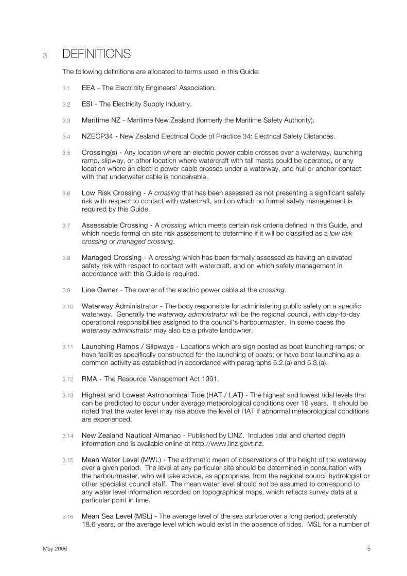
3 DEFINITIONS The following definitions are allocated to terms used in this Guide: 3.1 EEA - The Electricity Engineers’ Association.
3.2 ESI - The Electricity Supply Industry.
3.3 Maritime NZ - Maritime New Zealand (formerly the Maritime Safety Authority).
3.4 NZECP34 - New Zealand Electrical Code of Practice 34: Electrical Safety Distances.
3.5 Crossing(s) - Any location where an electric power cable crosses over a waterway, launching
ramp, slipway, or other location where watercraft with tall masts could be operated, or any location where an electric power cable crosses under a waterway, and hull or anchor contact with that underwater cable is conceivable.
3.6 Low Risk Crossing - A crossing that has been assessed as not presenting a significant safety
risk with respect to contact with watercraft, and on which no formal safety management is required by this Guide.
3.7 Assessable Crossing - A crossing which meets certain risk criteria defined in this Guide, and
which needs formal on site risk assessment to determine if it will be classified as a low risk crossing or managed crossing.
3.8 Managed Crossing - A crossing which has been formally assessed as having an elevated
safety risk with respect to contact with watercraft, and on which safety management in accordance with this Guide is required.
3.9 Line Owner - The owner of the electric power cable at the crossing.
3.10 Waterway Administrator - The body responsible for administering public safety on a specific
waterway. Generally the waterway administrator will be the regional council, with day-to-day operational responsibilities assigned to the council's harbourmaster. In some cases the waterway administrator may also be a private landowner.
3.11 Launching Ramps / Slipways - Locations which are sign posted as boat launching ramps; or
have facilities specifically constructed for the launching of boats; or have boat launching as a common activity as established in accordance with paragraphs 5.2.(a) and 5.3.(a).
3.12 RMA - The Resource Management Act 1991. 3.13 Highest and Lowest Astronomical Tide (HAT / LAT) - The highest and lowest tidal levels that
can be predicted to occur under average meteorological conditions over 18 years. It should be noted that the water level may rise above the level of HAT if abnormal meteorological conditions are experienced.
3.14 New Zealand Nautical Almanac - Published by LINZ. Includes tidal and charted depth
information and is available online at http://www.linz.govt.nz. 3.15 Mean Water Level (MWL) - The arithmetic mean of observations of the height of the waterway
over a given period. The level at any particular site should be determined in consultation with the harbourmaster, who will take advice, as appropriate, from the regional council hydrologist or other specialist council staff. The mean water level should not be assumed to correspond to any water level information recorded on topographical maps, which reflects survey data at a particular point in time.
3.16 Mean Sea Level (MSL) - The average level of the sea surface over a long period, preferably
18.6 years, or the average level which would exist in the absence of tides. MSL for a number of

May 2006 6
localities are available from the New Zealand Nautical Almanac and online at http://www.linz.govt.nz.
3.17 Sign Owner – The body responsible for installing the sign.
4 SCOPE This Guide covers the following areas: a. Identification of new and existing overhead and submarine crossings of navigable waterways,
boat launch ramps and slipways, which may pose a safety hazard to watercraft (assessable crossings).
b. Determination as to whether any assessable crossing warrants (or does not warrant) formal hazard management.
c. The design, placement and maintenance of appropriate warning signage for crossings that have been assessed as requiring formal hazard management.
d. Ongoing review of the conditions at managed crossings to identify any changes that may impact on the safety of the crossing.
5 IDENTIFICATION AND ASSESSMENT OF CROSSINGS
5.1 Responsibility Policy Responsibility for the identification, risk assessment and management of crossings is shared between the line owner and the waterway administrator. Paragraphs 5.2 and 5.3 detail the responsibility allocation.
5.2 Line Owner Responsibilities a. Identify all assessable crossings, in conjunction with the waterway administrator. b. Advise the waterway administrator in writing as to the location of assessable crossings. c. Assist the waterway administrator with on-site hazard assessments by providing the
available clearances determined in accordance with this Guide. d. Install and maintain the agreed type 1, 2, 3, or 5 signage, or other agreed safety
management systems on managed crossings. e. Advise LINZ of the location of all managed crossings. f. Advise the waterway administrator of any planned or actual changes to a managed
crossing which could in any way adversely affect the agreed management system or the likely safety outcomes.
g. Keeping records of all crossing assessments, correspondence and signage maintenance activities.
5.3 Waterway Administrator Responsibilities a. Assist the line owner as practicable with identifying assessable crossing locations. b. Conduct an on-site hazard assessment of each assessable crossing (crossing clearances
to be provided by the line owner). c. Discuss the hazard assessment with any other affected parties (e.g. landowners, yacht or
boating clubs). d. Make a determination as to whether the level of hazard presented is sufficient to warrant
it being upgraded to a managed crossing. e. For managed crossings, determine whether the crossing should be fitted with the
standard warning signage, modified signage, or other safety management options.1 f. Determine whether an RMA consent process is required to be followed, and if so ensure
the correct consent process is implemented. g. Advise the line owner and other affected parties in writing of any hazard assessments and
justify any judgements where these are outside the RMA process. h. Install and maintain any Type 4 signage required.
1 The line owner and the land owner must be involved in any negotiations over signage.
May 2006 7
i. Keeping records of all crossing assessments, correspondence and signage maintenance activities.
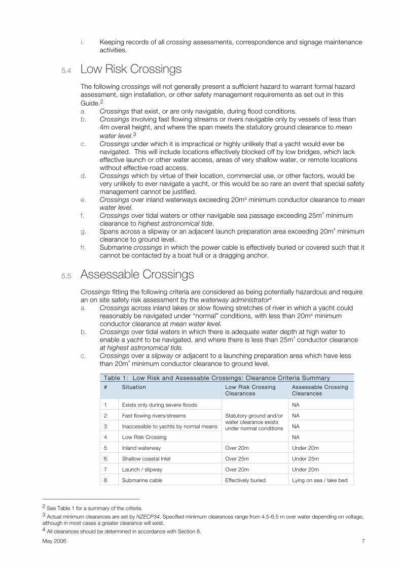
5.4 Low Risk Crossings The following crossings will not generally present a sufficient hazard to warrant formal hazard assessment, sign installation, or other safety management requirements as set out in this Guide.2 a. Crossings that exist, or are only navigable, during flood conditions. b. Crossings involving fast flowing streams or rivers navigable only by vessels of less than
4m overall height, and where the span meets the statutory ground clearance to mean water level.3
c. Crossings under which it is impractical or highly unlikely that a yacht would ever be navigated. This will include locations effectively blocked off by low bridges, which lack effective launch or other water access, areas of very shallow water, or remote locations without effective road access.
d. Crossings which by virtue of their location, commercial use, or other factors, would be very unlikely to ever navigate a yacht, or this would be so rare an event that special safety management cannot be justified.
e. Crossings over inland waterways exceeding 20m4 minimum conductor clearance to mean water level.
f. Crossings over tidal waters or other navigable sea passage exceeding 25m4 minimum clearance to highest astronomical tide.
g. Spans across a slipway or an adjacent launch preparation area exceeding 20m4 minimum clearance to ground level.
h. Submarine crossings in which the power cable is effectively buried or covered such that it cannot be contacted by a boat hull or a dragging anchor.
5.5 Assessable Crossings Crossings fitting the following criteria are considered as being potentially hazardous and require an on site safety risk assessment by the waterway administrator4 . a. Crossings across inland lakes or slow flowing stretches of river in which a yacht could
reasonably be navigated under “normal” conditions, with less than 20m4 minimum conductor clearance at mean water level.
b. Crossings over tidal waters in which there is adequate water depth at high water to enable a yacht to be navigated, and where there is less than 25m4 conductor clearance at highest astronomical tide.
c. Crossings over a slipway or adjacent to a launching preparation area which have less than 20m4 minimum conductor clearance to ground level.
Table 1: Low Risk and Assessable Crossings: Clearance Criteria Summary # Situation Low Risk Crossing
Clearances Assessable Crossing Clearances
1 Exists only during severe floods NA
2 Fast flowing rivers/streams NA
3 Inaccessible to yachts by normal means NA
4 Low Risk Crossing
Statutory ground and/or water clearance exists under normal conditions
NA
5 Inland waterway Over 20m Under 20m
6 Shallow coastal Inlet Over 25m Under 25m
7 Launch / slipway Over 20m Under 20m
8 Submarine cable Effectively buried Lying on sea / lake bed
2 See Table 1 for a summary of the criteria. 3 Actual minimum clearances are set by NZECP34. Specified minimum clearances range from 4.5-6.5 m over water depending on voltage, although in most cases a greater clearance will exist. 4 All clearances should be determined in accordance with Section 8.

May 2006 8
5.6 Systems and Records Waterway administrators and line owners shall each implement management systems capable of achieving the requirements of this guide relevant to them. This shall include records of all the risk assessments undertaken, so as to provide an audit trail of the hazard assessment process in the event of any crossing incident.
5.7 Dispute Resolution Should the situation arise where there are difficulties in obtaining a consensus agreement on the hazard assessment or management plans for any crossing, the details should be referred to independent arbitration.
6 SAFETY SIGNAGE
6.1 Sign Types Five standard sign types are defined in this Guide. It is envisaged that these will provide appropriate hazard warning for most managed crossings.
6.1.1 Type 1 and Type 2: Overhead Span Warning Signs These signs are for overhead crossings, and are for placing on the shore or line support structures on each side of the crossing so that the signs are visible from vessels approaching or transiting under or along the span (see Appendices A and B for the details of these signs, and Appendix F for mounting details).
6.1.2 Type 3: Launching Area Hazard Sign This is a warning sign placed in the vicinity of slipways warning of low spans across the launch area (see Appendix C for the details of this sign).
6.1.3 Type 4: Caution Low Spans in Vicinity Sign This sign is placed adjacent to slipways and launching areas, warning of power line crossings somewhere out on the waterway (see Appendix D for the details of this sign). The requirement for these signs will usually be determined by the circumstances of each particular case including the usage of the ramps/sites in question, and by the RMA consent process.
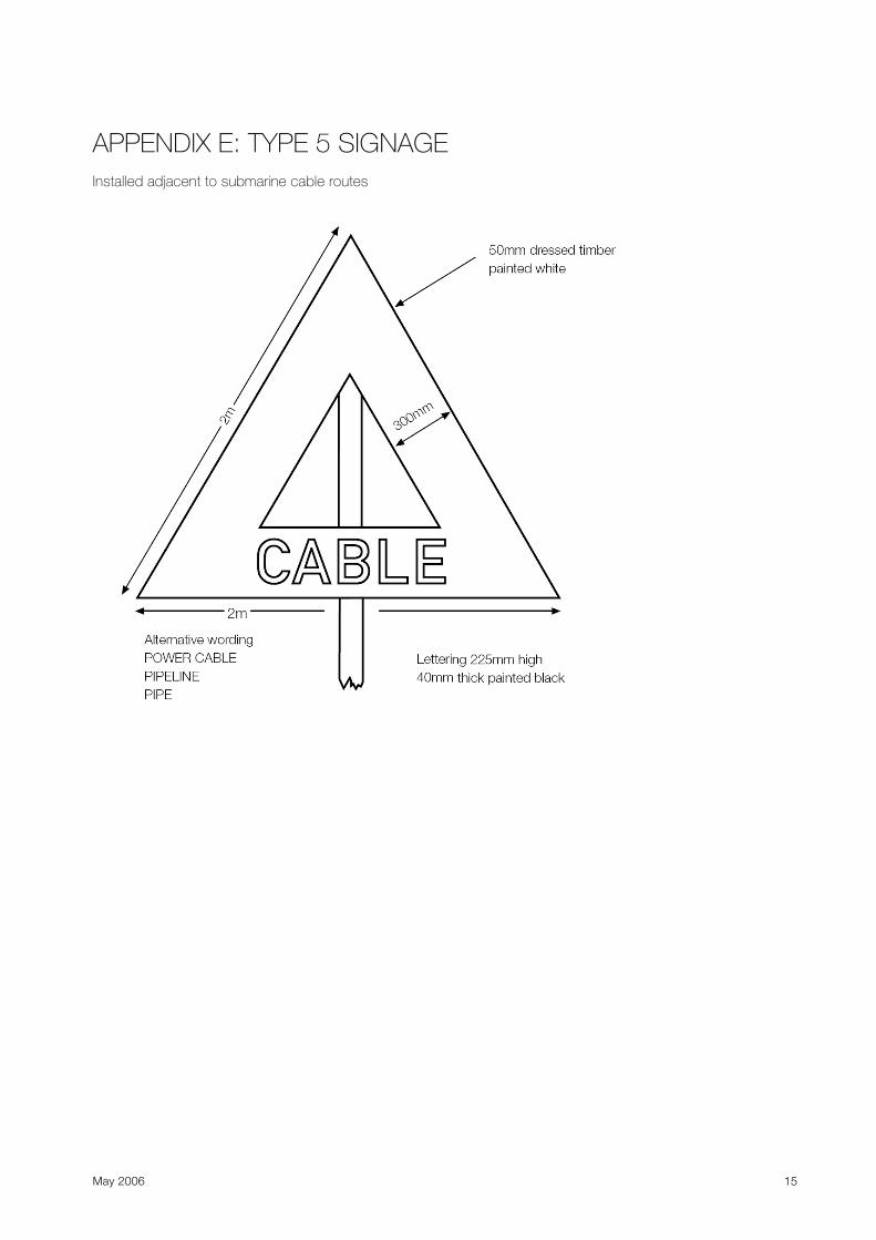
6.1.4 Type 5: Caution Submarine Cable Sign This sign is placed at either end of a submarine cable crossing. The sign warns of the electrical hazards associated with disturbing the harbour, river or lakebed (e.g. by dragging an anchor, undertaking drilling, or dredging, etc) (see Appendix E for the details of this sign).
6.2 Sign Design The design of the standard signage is set out in Appendix A to E. All detailed sign design, sign size, sign colour, and the font type and sizes used should comply with NZS 8690 where appropriate. Where for any reason the standard signage is not considered appropriate or effective, the design may be varied provided the safety outcome is improved. The design of any special or varied signage must be agreed to by the waterway administrator, and preferably also approved by Maritime NZ. In all cases, sign design, numbers and placing is governed by the RMA and any district plan restrictions relating to signage (see also Section 7).

May 2006 9
6.3 Sign Placement Type 1 and Type 2 signs should where practicable, comply with the placement and size criteria specified in Appendix F. The signs should be positioned as close to the waters edge as practical (or even in the waterway) but located so as not to create an obstruction to normal use of the waterway or beach area. Signs should be placed on the crossing support structures (towers or poles) where this is appropriate. The signs must be clearly visible when approaching the lowest point of any span, as well as when directly under it.
Type 3 signs must be placed in prominent positions adjacent to the likely crossing location. Where the crossing location is very wide (greater than 30m), a sign should be placed on each side. Type 4 signs must be placed adjacent to each slipway in a prominent position near the high water line. The waterway administrator is responsible for installation and maintenance of these signs.
Type 5 signs must be placed at either end of the crossing, and may in some cases need to be supplemented with an additional signage stating what is under the waterway (cable numbers and voltages, etc) and which activities are hazardous, (e.g. no anchoring, or dredging, etc).
6.4 Sign Maintenance All safety signage or other safety measures put in place must be maintained by the sign owner in such a condition that they: a. Are clearly legible (e.g. not obscured or excessively faded). b. Are physically intact and secure on their mounting. c. Are clear of obscuring vegetation, moss or mildew. d. Accurately display the maximum vessel height where required. Sign owners must ensure that their signs are maintained to the above standards under the management system required under section 5.6 of this Guide.
7 RESOURCE MANAGEMENT ACT CONSIDERATIONS Section 13 of the RMA, places regulatory control on the placement of structures (cables) in, on, under or over the bed of a lake or stream. Section 12 places the same restriction on structures in the coastal marine area. Unless a regional council has permitted the activity in a regional plan rule, consent will be required for new or amended crossings, and for the installation of new or significantly amended signage. Discussion with the relevant regional council will indicate actual consent requirements. District and city councils may also have the placement of signage as a permitted activity; however in other cases they may require consent under the RMA for the erection of a structure and/or associated signage. Again, early discussion with the relevant territorial local authority is recommended.
8 DETERMINING SAFE ELECTRICAL CLEARANCES
8.1 Establishing Clearances The actual clearances available at any crossing shall be established by the line owner (as required by paragraph 5.2 (c)) based on the following criteria (see also Figure 1).
8.2 Type 2 Signs The Maximum Safe Vessel Height above the waterline stated on Type 2 signs, shall be determined by calculating: a. The minimum available clearance from risk Case 1 or Case 2 below:

May 2006 10
i Case 1 - The mean water level (inland waterways) or mean sea level, with the maximum design conductor temperature for that line (eg. 50, 75, 90, 120º C as appropriate); or
ii Case 2 - Maximum design flood level (inland waterways), or highest astronomical tide5 (for the sea) with a 35° C conductor temperature; and
b. deducting the Electrical Flashover Distance from Table 2 below; and c. deducting the Safety Margin from Table 2 below.
8.3 Electrical Flashover and Safety Distances Electrical flashover and safety distances are determined from Table 2 as follows:
Table 2: Flashover Distances and Safety Margins by Line Voltage
Circuit Voltage Up to 33 kV 50-110 kV 220 kV 350 kVDC 400kV
Flashover Distance 0.2m 0.7m 1.3m 1.5m 2.0m
Safety Margin 1.0m 1.0m 1.0m 1.0m 1.0m
Total Electrical Safety Distance 1.2m 1.7m 2.3m 2.5m 3.0m
8.4 Type 3 Signs The Maximum Safe Vessel Height above ground level at maximum design conductor temperature stated on Type 3 signs shall be calculated in the following manner: a. Establish the minimum clearance to ground level at maximum design conductor
temperature for that line (ie. 50, 75, 90, 120° C as appropriate), and b. deducting the Electrical Flashover Distance from Table 2 above; and c. deducting the Safety Margin from Table 2 above.
9 CHANGED CIRCUMSTANCES AND NEW CROSSINGS
9.1 Changed Circumstances It is essential that managed crossings are periodically reassessed for a possible increase in safety hazards to watercraft users. This action is the prime responsibility of the waterway
5 HAT levels for a number of ports are available in the New Zealand Nautical Almanac. For waterways in other areas, HAT can be determined by reference to the tidal information in the Almanac and the charted depth for that locality. The HAT is the difference between the depth of water appearing on official navigational charts (which is set at the approximate level of the lowest astronomical tide - LAT) for that locality and the mean sea level multiplied by two. HAT and LAT when expressed relative to MSL have equal magnitude but opposite sign. This methodology is approximate and depending on the proximity of the tidal station from which chart datum was derived may not provide an accurate result.

May 2006 11
administrator, but the line owner may also suggest a reassessment should they become aware of changed circumstances, or where the crossing height is altered for any reason. Where any crossing is the subject of a contact event (or a known near-miss event) irrespective of whether injuries or vessel damage actually occurred or not, the crossing is to be subjected to a reassessment. Changed circumstances may also occur at an existing low risk or assessed crossing, where an alteration to either the waterway, or its usage, may have increased the level of hazard. Examples would be dredging to increase the depth or width of an existing waterway, or the damming of a stream to create a lake. Both the waterway administrator and the line owner need to be alert for any such situations. Where the waterway administrator identifies that alteration of a crossing height may be a desirable option due to changes in the characteristics of a waterway or the watercraft typically navigating the crossing area, the waterway administrator should seek negotiation with the line owner and other affected parties as appropriate, as to the costs and practicality of increasing the clearance. New construction or significant alterations to existing crossings may involve considerable cost, may be constrained by RMA requirements in regional plans, and there may also be resistance from other affected parties such as adjacent landowners. Where an existing managed crossing is modified by the line owner, NZECP34 requires the line owner to consult with the MSA (now Maritime NZ) to facilitate a further hazard assessment if required.
9.2 New Crossings Where new crossings are planned, the line owner must consult with the waterway administrator to facilitate a hazard assessment, and if required, apply for resource consent.
10 SAFETY MANAGEMENT OTHER THAN SIGNAGE
10.1 Alternative Safety Management Options As not all crossings will necessarily be well suited to fitting the standard signage, improved safety outcomes may be able to be achieved (and potentially at lesser cost) by alternative measures. These measures will be specific to each site, but possibilities to consider are: a. Signs or markers supported on the overhead crossing itself.
Note 1: In some locations aircraft may be frequent users of the waterway, (float planes, paragliding, hang-gliders etc) and the fitting of aircraft marker balls may have an added safety advantage. Where aircraft style marker balls are fitted, the highest wire on the crossing must be marked for aircraft as well as the lowest wire for yachts to ensure that the marking is consistent with both standard aviation and marine navigation requirements. Note 2: Where the banks of the waterway are heavily bush covered or may be obscured by regular flooding etc, the marking of the span itself may be a more effective option.
b. Physical barriers or other obstructions placed in the waterway preventing navigation under the span.
c. Signage mounted on buoys placed in the waterway under the span.
10.2 Introduction of the New Requirements to Users This Guide puts in place significant changes to the existing safety clearance system, both in terms of signage presentation and the safety distances presented on the signage. Watercraft users have become accustomed to the existing warning signs which display very conservative safety clearances. Therefore some users may fail to heed the new signs expecting that the safe clearances they convey still involve considerable tolerance for over-height masts.
May 2006 12
For this reason, it will be important for the waterway administrators to re-educate the boating fraternity about the new signage. This process needs to reinforce the message that they are based on new and more realistic criteria, that there are no longer large margins for error on mast height. All boat owners should therefore know their mast heights accurately. Wherever practical, mast height should be marked prominently on the mast base so all skippers have ready, rapid and reliable access to this key safety information.
APPENDICES The following appendices form a part of this Guide:
Appendix A: Type 1 Signage Design
Appendix B: Type 2 Signage Design
Appendix C: Type 3 Signage Design
Appendix D: Type 4 Signage Design
Appendix E: Type 5 Signage Design
Appendix F: Installation of Type 1 and 2 Signs

May 2006 13
APPENDIX A: TYPE 1 SIGN Installed each side of an overhead line crossing
APPENDIX B: TYPE 2 SIGN Installed each side of an overhead line crossing

May 2006 14
APPENDIX C: TYPE 3 SIGN Installed on slipways where there are overhead line crossings
APPENDIX D: TYPE 4 SIGN Installed on slipways accessing waterways where there are overhead crossings
May 2006 15
APPENDIX E: TYPE 5 SIGNAGE Installed adjacent to submarine cable routes

May 2006 16
APPENDIX F Installation of Type 1 and Type 2 Signage