safety light curtains - xusl - schneider-electric.com · the k3 and k4 relays must have forced...
TRANSCRIPT

Safety Light curtains - XUSL
Connection Schematics
The wiring from the XUSL2E/XUSL4E light curtain system to the machine control circuit must be control reliable. The solid-state outputs should be connected only to a control reliable, safety-rated PLC or to a control reliable safety-rated machine system.
1
Standalone application ................................................................ 2
XPS-AK safety module ................................................................. 3
XPS-AFL safety module ................................................................ 4
XPSMCMER relay module ............................................................ 5
XPSMC safety controller ............................................................... 6
XPSMCM safety controller ............................................................ 7
Table of Contents

OSSD1/OSSD2 : Output signal switching device
YE/GN OR RD : Yellow/Green OR RedBU : BlueBN : BrownGY : GreyYE : YellowPK : PinkWH : WhiteGN : GreenBK/WH : Black/WhiteBK : Black
2
Standalone application
Example of wiring diagram with manual start, external device monitoring and low range
When used in standalone mode, the XUSL2E and XUSL4E are compliant with the following standards respectively : Type 2 (IEC 61496-1), SIL1 (IEC 61508) - SILCL1 (IEC 62061), and PLc- Cat.2 (EN ISO 13849-1:2008). Type 4 (IEC 61496-1), SIL3 (IEC 61508) SILCL3 (IEC 62061), and PLe- Cat.4 (EN ISO 13849-1:2008).
It is the aim of the risk analysis to determine whether the use of type 2 or type 4 standalone safety light curtains are compatible with the expected safety level of the entire system.
The K1 and K2 relays must have normally closed mirror contact (according to IEC 60947-4-1 for power contactors) and forced guided contacts (according to IEC 60947-5-1 or EN 50205 for auxiliary contactors or control relays).

Connecting to a Safety Monitoring Device
Example of wiring diagram with the XPS-AK safety module
(1) Operating status of internal electronic fuse(2) ESPE indicator light deactivatedESC : External start conditionsESPE : Electro-sensitive protection equipmentOSSD1/OSSD2 : Output signal switching device
The K3 and K4 relays must have forced guided contacts.
Automatic start is possible by removing the start button in the schematic above (short circuit instead) and by connecting directly S13 to S14.
For any start mode, the receiver must be configured by wiring in automatic start and without EDM (External Device Monitoring).
3

Connecting to a Safety Monitoring Device
OSSD1/OSSD2 : Output signal switching device
and without EDM (External Device Monitoring) .
Automatic start is not allowed with the XPS-AFL module (between terminals S33 and S39).
The maximum cable length between the terminals S33 and S34 must be between 3 to 5 m.
The K3 and K4 relays must have forced guided contacts.
4

Connecting to a Safety Monitoring Device
Example of wiring diagram with an XPSMCMER safety relay output extension module in manual start with EDM (External Device Monitoring)
OSSD1/OSSD2 : Output signal switching device
The K1 and K2 relays must have forced guided contacts.
The XPSMCMER safety relay output extension modules do not require a CPU unit XPSMCMCP as they are connected directly to the safety light curtains OSSDs.
For the association with XPSCMCER, the operating modes (manual or automatic start) and EDM must be configured by wiring on the receiver. For example, in the schematic above, automatic start is possible by removing the start button (short circuit instead) and by configuring the receiver in automatic start, with EDM.
5
6
Connecting to a Safety Monitoring Device
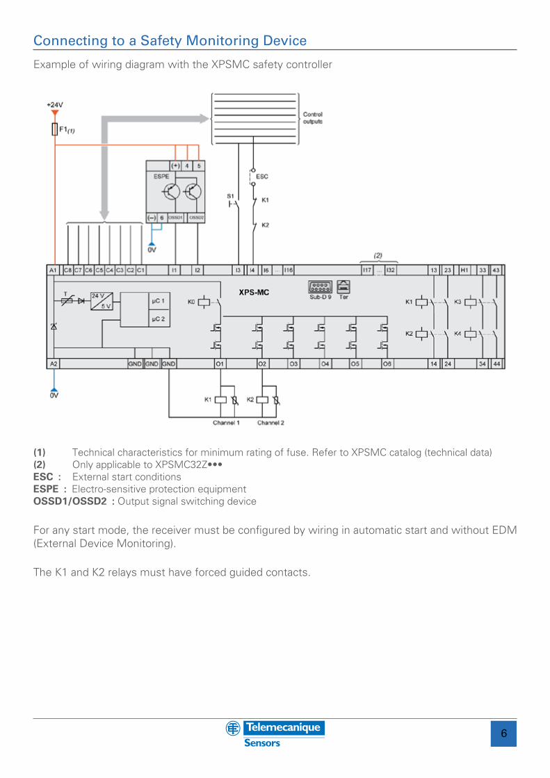
Example of wiring diagram with the XPSMC safety controller
(1) Technical characteristics for minimum rating of fuse. Refer to XPSMC catalog (technical data)(2) Only applicable to XPSMC32Z•••ESC : External start conditionsESPE : Electro-sensitive protection equipmentOSSD1/OSSD2 : Output signal switching device
The K1 and K2 relays must have forced guided contacts.
For any start mode, the receiver must be configured by wiring in automatic start and without EDM (External Device Monitoring).

7
Connecting to a Safety Monitoring Device
Example of wiring diagram with the XPSMCM safety controller
OSSD1/OSSD2 : Output signal switching device
The K1 and K2 relays must have forced guided contacts.
For any start mode, the receiver must be configured by wiring in automatic start and without EDM (External Device Monitoring).