safe.t® solutions
TRANSCRIPT

Safe.t® Technology Safe.t® Seminars Safe.t® Solutions Safe.t® Components Safe.t® Systems
Safe.t® Solutions Safe.t® Components Safe.t® Systems Safe.t® Technology
Safe.t® Technology Safe.t® Seminars Safe.t® Solutions Safe.t® Systems
Safe.t® Solutions Safe.t® Components Safe.t® Systems Safe.t® Technology
Safe.t® Technology Safe.t® Seminars Safe.t® Solutions Safe.t® Components Safe.t® Systems
Mining electrical engineering
21
Flame-proof encoder type OE-1.*
Explosion-proof protection
Marking I M2 Ex d [ib] I Mb II 2G Ex d [ib] IIA T4 Gb Ambient temperature
-200C to +400C
CE Type Examination Certificate
OBAC 08 ATEX 255
Rated data
Ingress protection IP65
Parameters of intrinsically safe outputs of
signal (3,4) Co = 7000uF Lo = 220mH Io = 65mA Uo = 6.51V Po = 0.212mW
Parameters of intrinsically safe intputs of
signal (5,6) Ci - negligible
Lo - negligible Ii = 14mA Ui = 5.5V
Supply parameters (1,2) Ui = 12.8V Ii = 0.427A Ci - negligible Li - negligible
Dimensions length: 170mm,
diameter: 130 mm Weight
approx. 11 kg
Properties
measurement of rotation angle,
measurement of rotational spe-ed,
small overall dimensions.
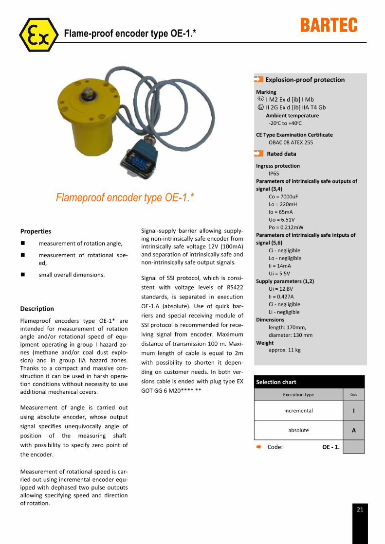
Flameproof encoder type OE-1.*
Description
Flameproof encoders type OE-1* are intended for measurement of rotation angle and/or rotational speed of equ-ipment operating in group I hazard zo-nes (methane and/or coal dust explo-sion) and in group IIA hazard zones. Thanks to a compact and massive con-struction it can be used in harsh opera-tion conditions without necessity to use additional mechanical covers.
Measurement of angle is carried out
using absolute encoder, whose output
signal specifies unequivocally angle of
position of the measuring shaft
with possibility to specify zero point of
the encoder.
Measurement of rotational speed is car-ried out using incremental encoder equ-ipped with dephased two pulse outputs allowing specifying speed and direction of rotation.
Signal-supply barrier allowing supply-ing non-intrinsically safe encoder from intrinsically safe voltage 12V (100mA) and separation of intrinsically safe and non-intrinsically safe output signals.
Signal of SSI protocol, which is consi-
stent with voltage levels of RS422
standards, is separated in execution
OE-1.A (absolute). Use of quick bar-
riers and special receiving module of
SSI protocol is recommended for rece-
iving signal from encoder. Maximum
distance of transmission 100 m. Maxi-
mum length of cable is equal to 2m
with possibility to shorten it depen-
ding on customer needs. In both ver-
sions cable is ended with plug type EX
GOT GG 6 M20**** **
Selection chart
Execution type Code
incremental I
absolute A
Code: OE - 1.
22
Intrinsically safe incremental encoder type IEI-1
Properties
measurement of rotational spe-ed,
small overall dimensions.
Explosion-proof protection
Marking
I M1 Ex ia I II 1G Ex ia tDA20 IP66 IIB T4
Ambient temperature -200C to +700C
CE Type Examination Certificate
OBAC 09 ATEX 255
Rated data
Ingress protection IP66
Parameters of intrinsically safe outputs of signal (2-3;2-4;2-5)
Io = 95.45mA Uo = 27.5V Po = 0.66W Co for I = 3.55 µF Lo for I = 51.22 mH Co for IIA = 2.42 µF Lo for IIA = 31.22 mH Co for IIB = 0.672 µF Lo for IIB = 15.61 mH
Supply parameters (1-2) Ui = 28V Pi = 2.33 W Ci - 0.6 µF Li - 0 H
Number of pulses of incremental encoder up to 1024 imp./rev. Maximum rotational speed
to 3600 rev./min
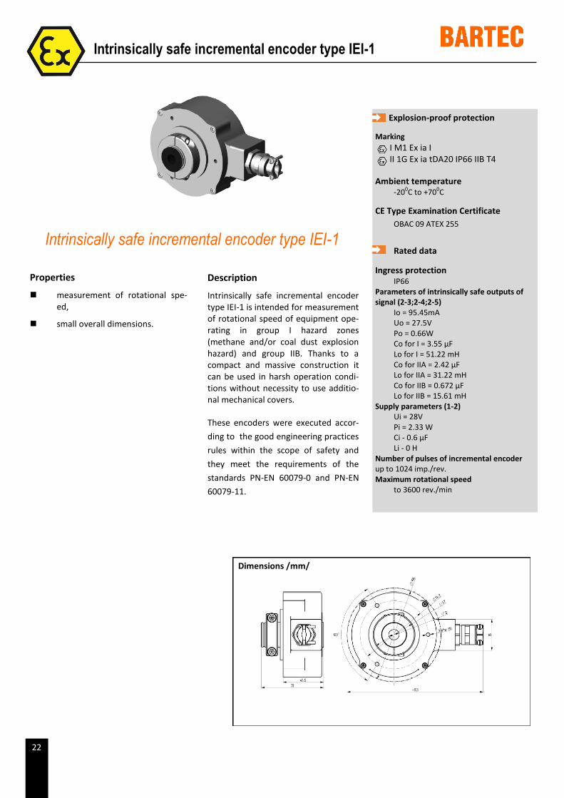
Intrinsically safe incremental encoder type IEI-1
Description
Intrinsically safe incremental encoder type IEI-1 is intended for measurement of rotational speed of equipment ope-rating in group I hazard zones (methane and/or coal dust explosion hazard) and group IIB. Thanks to a compact and massive construction it can be used in harsh operation condi-tions without necessity to use additio-nal mechanical covers.
These encoders were executed accor-
ding to the good engineering practices
rules within the scope of safety and
they meet the requirements of the
standards PN-EN 60079-0 and PN-EN
60079-11.
Dimensions /mm/
23
Description
Converter of intrinsically safe encoders
type PEI-*.* is intended for supplying
incremental encoders with intrinsically
safe voltage and separation of signals
from encoder.
Explosion-proof protection
Marking I M2 [Ex ia] I II 2G [Ex ia] IIB T4
Ambient temperature -200C to +700C
CE Type Examination Certificate OBAC 09 ATEX 408U
Rated data
Ingress protection IP20
Please refer to the Owner’s Handbook for details of the Start Up Procedure.
Intrinsically safe encoders converter type PEI-*.*
Properties
supplies incremental encoders with intrinsically safe voltage,
separation of signals from enco-der,
possibility to use as intrinsically
safe power unit and signals sepa-
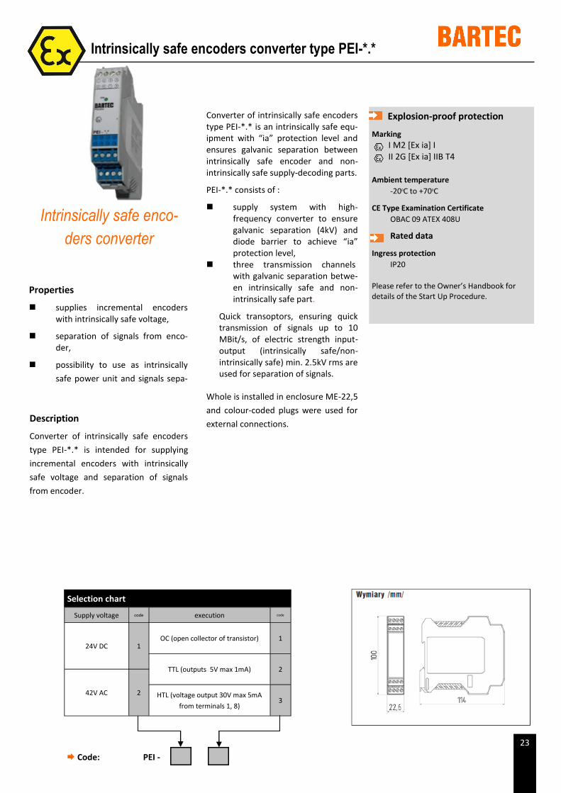
Converter of intrinsically safe encoders type PEI-*.* is an intrinsically safe equ-ipment with “ia” protection level and ensures galvanic separation between intrinsically safe encoder and non-intrinsically safe supply-decoding parts.
PEI-*.* consists of :
supply system with high-frequency converter to ensure galvanic separation (4kV) and diode barrier to achieve “ia” protection level,
three transmission channels with galvanic separation betwe-en intrinsically safe and non-intrinsically safe part.
Quick transoptors, ensuring quick transmission of signals up to 10 MBit/s, of electric strength input-output (intrinsically safe/non-intrinsically safe) min. 2.5kV rms are used for separation of signals.
Whole is installed in enclosure ME-22,5
and colour-coded plugs were used for
external connections.
Intrinsically safe enco-
ders converter
Selection chart
Supply voltage code execution code
24V DC 1 OC (open collector of transistor) 1
TTL (outputs 5V max 1mA) 2
42V AC 2 HTL (voltage output 30V max 5mA
from terminals 1, 8) 3
Code: PEI -
24
Description
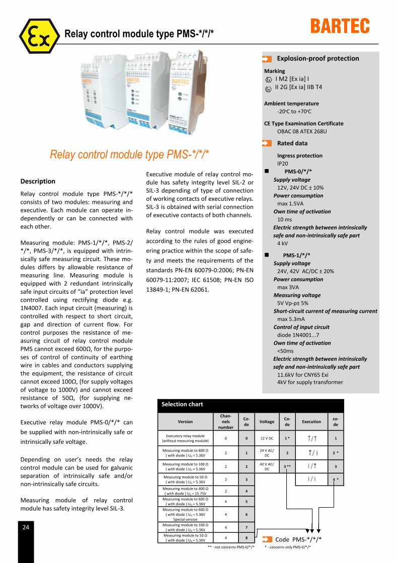
Relay control module type PMS-*/*/* consists of two modules: measuring and executive. Each module can operate in-dependently or can be connected with each other.
Measuring module: PMS-1/*/*, PMS-2/*/*, PMS-3/*/*, is equipped with intrin-sically safe measuring circuit. These mo-dules differs by allowable resistance of measuring line. Measuring module is equipped with 2 redundant intrinsically safe input circuits of “ia” protection level controlled using rectifying diode e.g. 1N4007. Each input circuit (measuring) is controlled with respect to short circuit, gap and direction of current flow. For control purposes the resistance of me-asuring circuit of relay control module PMS cannot exceed 600Ω, for the purpo-ses of control of continuity of earthing wire in cables and conductors supplying the equipment, the resistance of circuit cannot exceed 100Ω, (for supply voltages of voltage to 1000V) and cannot exceed resistance of 50Ω, (for supplying ne-tworks of voltage over 1000V).
Executive relay module PMS-0/*/* can
be supplied with non-intrinsically safe or
intrinsically safe voltage.
Depending on user’s needs the relay control module can be used for galvanic separation of intrinsically safe and/or non-intrinsically safe circuits.
Measuring module of relay control module has safety integrity level SIL-3.
Explosion-proof protection
Marking I M2 [Ex ia] I II 2G [Ex ia] IIB T4
Ambient temperature -200C to +700C
CE Type Examination Certificate OBAC 08 ATEX 268U
Rated data
Ingress protection IP20
PMS-0/*/* Supply voltage
12V, 24V DC ± 10% Power consumption
max 1.5VA Own time of activation
10 ms Electric strength between intrinsically
safe and non-intrinsically safe part 4 kV
PMS-1/*/* Supply voltage
24V, 42V AC/DC ± 20% Power consumption
max 3VA Measuring voltage
5V Vp-p± 5% Short-circuit current of measuring current
max 5.3mA Control of input circuit
diode 1N4001...7 Own time of activation
<50ms Electric strength between intrinsically
safe and non-intrinsically safe part 11.6kV for CNY65 Exi 4kV for supply transformer
Relay control module type PMS-*/*/*
Executive module of relay control mo-dule has safety integrity level SIL-2 or SIL-3 depending of type of connection of working contacts of executive relays. SIL-3 is obtained with serial connection of executive contacts of both channels.
Relay control module was executed
according to the rules of good engine-
ering practice within the scope of safe-
ty and meets the requirements of the
standards PN-EN 60079-0:2006; PN-EN
60079-11:2007; IEC 61508; PN-EN ISO
13849-1; PN-EN 62061.
Relay control module type PMS-*/*/*
Selection chart
Version Chan-nels
number
Co-de Voltage Co-
de Execution co-de
Executory relay module (without measuring module) 0 0 12 V DC 1 *
1
Measuring module to 600 Ω ( with diode ) U0 = 5.36V 2 1 24 V AC/
DC 2
2 *
Measuring module to 100 Ω ( with diode ) U0 = 5.36V 2 2 42 V AC/
DC 3 **
3
Measuring module to 50 Ω ( with diode ) U0 = 5.36V 2 3
4 *
Measuring module to 400 Ω ( with diode ) U0 = 15.75V 2 4
Measuring module to 600 Ω ( with diode ) U0 = 5.36V 4 5
Measuring module to 600 Ω ( with diode ) U0 = 5.36V
Special version 4 6
Measuring module to 100 Ω ( with diode ) U0 = 5.36V 4 7
Measuring module to 50 Ω ( with diode ) U0 = 5.36V 4 8 Code PMS-*/*/*
* - concerns only PMS-0/*/* ** - not concerns PMS-0/*/*
25
Description
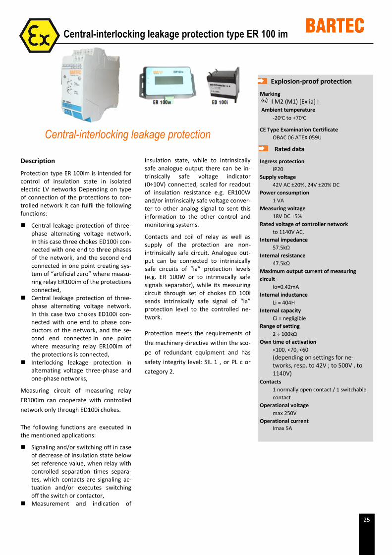
Protection type ER 100im is intended for control of insulation state in isolated electric LV networks Depending on type of connection of the protections to con-trolled network it can fulfil the following functions:
Central leakage protection of three-phase alternating voltage network. In this case three chokes ED100i con-nected with one end to three phases of the network, and the second end connected in one point creating sys-tem of “artificial zero” where measu-ring relay ER100im of the protections connected,
Central leakage protection of three-phase alternating voltage network. In this case two chokes ED100i con-nected with one end to phase con-ductors of the network, and the se-cond end connected in one point where measuring relay ER100im of the protections is connected,
Interlocking leakage protection in alternating voltage three-phase and one-phase networks,
Measuring circuit of measuring relay
ER100im can cooperate with controlled
network only through ED100i chokes.
The following functions are executed in the mentioned applications:
Signaling and/or switching off in case of decrease of insulation state below set reference value, when relay with controlled separation times separa-tes, which contacts are signaling ac-tuation and/or executes switching off the switch or contactor,
Measurement and indication of
Explosion-proof protection
Marking I M2 (M1) [Ex ia] I
Ambient temperature -200C to +700C
CE Type Examination Certificate OBAC 06 ATEX 059U
Rated data
Ingress protection IP20
Supply voltage 42V AC ±20%, 24V ±20% DC
Power consumption 1 VA
Measuring voltage 18V DC ±5%
Rated voltage of controller network to 1140V AC,
Internal impedance 57.5kΩ
Internal resistance 47.5kΩ
Maximum output current of measuring circuit
Io=0.42mA Internal inductance
Li = 404H Internal capacity
Ci = negligible Range of setting
2 ÷ 100kΩ Own time of activation
<100, <70, <60 (depending on settings for ne-tworks, resp. to 42V ; to 500V , to 1140V)
Contacts 1 normally open contact / 1 switchable
contact Operational voltage
max 250V Operational current
Imax 5A
Central-interlocking leakage protection type ER 100 im
insulation state, while to intrinsically safe analogue output there can be in-trinsically safe voltage indicator (0÷10V) connected, scaled for readout of insulation resistance e.g. ER100W and/or intrinsically safe voltage conver-ter to other analog signal to sent this information to the other control and monitoring systems.
Contacts and coil of relay as well as supply of the protection are non-intrinsically safe circuit. Analogue out-put can be connected to intrinsically safe circuits of “ia” protection levels (e.g. ER 100W or to intrinsically safe signals separator), while its measuring circuit through set of chokes ED 100i sends intrinsically safe signal of “ia” protection level to the controlled ne-twork.
Protection meets the requirements of
the machinery directive within the sco-
pe of redundant equipment and has
safety integrity level: SIL 1 , or PL c or
category 2.
Central-interlocking leakage protection
27
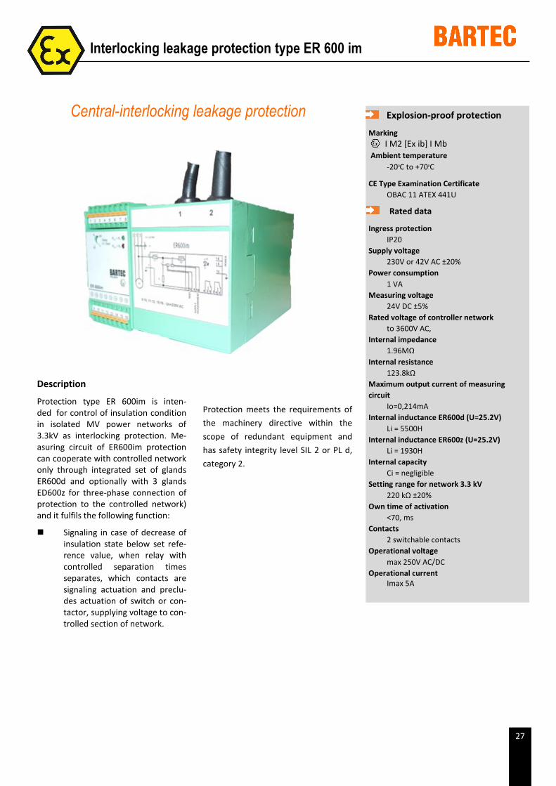
Description
Protection type ER 600im is inten-ded for control of insulation condition in isolated MV power networks of 3.3kV as interlocking protection. Me-asuring circuit of ER600im protection can cooperate with controlled network only through integrated set of glands ER600d and optionally with 3 glands ED600z for three-phase connection of protection to the controlled network) and it fulfils the following function:
Signaling in case of decrease of insulation state below set refe-rence value, when relay with controlled separation times separates, which contacts are signaling actuation and preclu-des actuation of switch or con-tactor, supplying voltage to con-trolled section of network.
Explosion-proof protection
Marking I M2 [Ex ib] I Mb
Ambient temperature -200C to +700C
CE Type Examination Certificate OBAC 11 ATEX 441U
Rated data
Ingress protection IP20
Supply voltage 230V or 42V AC ±20%
Power consumption 1 VA
Measuring voltage 24V DC ±5%
Rated voltage of controller network to 3600V AC,
Internal impedance 1.96MΩ
Internal resistance 123.8kΩ
Maximum output current of measuring circuit
Io=0,214mA Internal inductance ER600d (U=25.2V)
Li = 5500H Internal inductance ER600z (U=25.2V)
Li = 1930H Internal capacity
Ci = negligible Setting range for network 3.3 kV
220 kΩ ±20% Own time of activation
<70, ms Contacts
2 switchable contacts Operational voltage
max 250V AC/DC Operational current
Imax 5A
Interlocking leakage protection type ER 600 im
Central-interlocking leakage protection
Protection meets the requirements of
the machinery directive within the
scope of redundant equipment and
has safety integrity level SIL 2 or PL d,
category 2.
29
Description
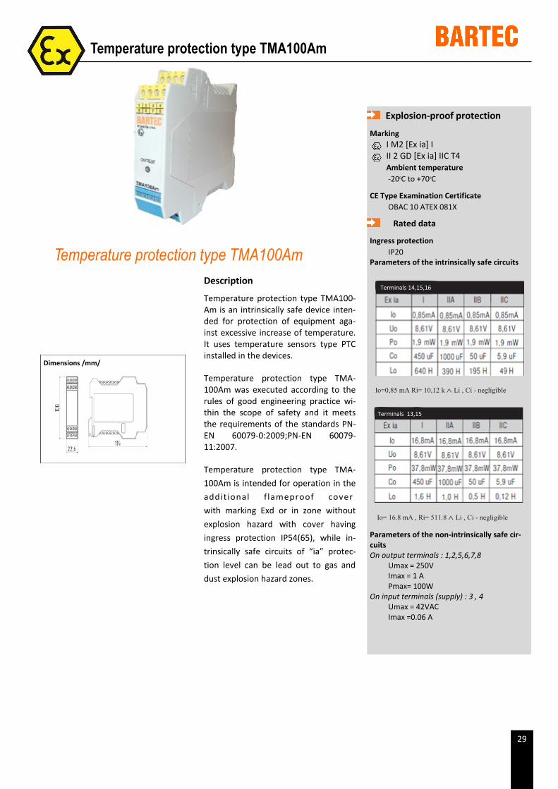
Temperature protection type TMA100-Am is an intrinsically safe device inten-ded for protection of equipment aga-inst excessive increase of temperature. It uses temperature sensors type PTC installed in the devices.
Temperature protection type TMA-100Am was executed according to the rules of good engineering practice wi-thin the scope of safety and it meets the requirements of the standards PN-EN 60079-0:2009;PN-EN 60079-11:2007.
Temperature protection type TMA-
100Am is intended for operation in the
additional f lameproof cover
with marking Exd or in zone without
explosion hazard with cover having
ingress protection IP54(65), while in-
trinsically safe circuits of “ia” protec-
tion level can be lead out to gas and
dust explosion hazard zones.
Explosion-proof protection
Marking I M2 [Ex ia] I II 2 GD [Ex ia] IIC T4 Ambient temperature
-200C to +700C
CE Type Examination Certificate OBAC 10 ATEX 081X
Rated data
Ingress protection IP20
Parameters of the intrinsically safe circuits
Io=0,85 mA Ri= 10,12 k Li , Ci - negligible
Io= 16.8 mA , Ri= 511.8 Li , Ci - negligible
Parameters of the non-intrinsically safe cir-cuits On output terminals : 1,2,5,6,7,8
Umax = 250V Imax = 1 A Pmax= 100W
On input terminals (supply) : 3 , 4 Umax = 42VAC Imax =0.06 A
Temperature protection type TMA100Am
Temperature protection type TMA100Am
Terminals 14,15,16
Terminals 13,15
Dimensions /mm/
30
Description
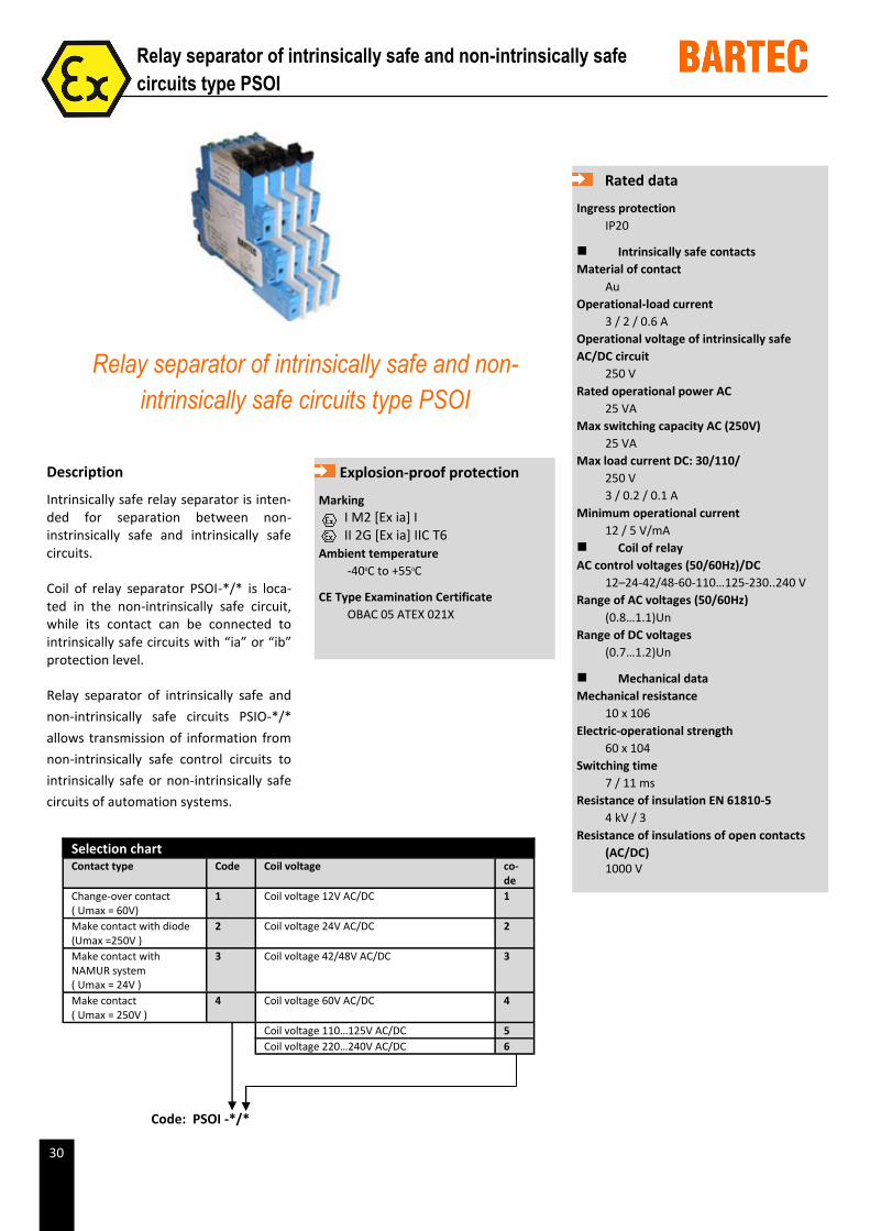
Intrinsically safe relay separator is inten-ded for separation between non-instrinsically safe and intrinsically safe circuits.
Coil of relay separator PSOI-*/* is loca-ted in the non-intrinsically safe circuit, while its contact can be connected to intrinsically safe circuits with “ia” or “ib” protection level.
Relay separator of intrinsically safe and
non-intrinsically safe circuits PSIO-*/*
allows transmission of information from
non-intrinsically safe control circuits to
intrinsically safe or non-intrinsically safe
circuits of automation systems.
Rated data
Ingress protection IP20
Intrinsically safe contacts Material of contact
Au Operational-load current
3 / 2 / 0.6 A Operational voltage of intrinsically safe AC/DC circuit
250 V Rated operational power AC
25 VA Max switching capacity AC (250V)
25 VA Max load current DC: 30/110/
250 V 3 / 0.2 / 0.1 A
Minimum operational current 12 / 5 V/mA
Coil of relay AC control voltages (50/60Hz)/DC
12–24-42/48-60-110…125-230..240 V Range of AC voltages (50/60Hz)
(0.8…1.1)Un Range of DC voltages
(0.7…1.2)Un
Mechanical data Mechanical resistance
10 x 106 Electric-operational strength
60 x 104 Switching time
7 / 11 ms Resistance of insulation EN 61810-5
4 kV / 3 Resistance of insulations of open contacts
(AC/DC) 1000 V
Relay separator of intrinsically safe and non-
intrinsically safe circuits type PSOI
Relay separator of intrinsically safe and non-intrinsically safe
circuits type PSOI
Explosion-proof protection
Marking I M2 [Ex ia] I II 2G [Ex ia] IIC T6
Ambient temperature -400C to +550C
CE Type Examination Certificate OBAC 05 ATEX 021X
Code: PSOI -*/*
Selection chart Contact type Code Coil voltage co-
de
Change-over contact ( Umax = 60V)
1 Coil voltage 12V AC/DC 1
Make contact with diode (Umax =250V )
2 Coil voltage 24V AC/DC 2
Make contact with NAMUR system ( Umax = 24V )
3 Coil voltage 42/48V AC/DC 3
Make contact ( Umax = 250V )
4 Coil voltage 60V AC/DC 4
Coil voltage 110…125V AC/DC 5
Coil voltage 220…240V AC/DC 6
31
Description
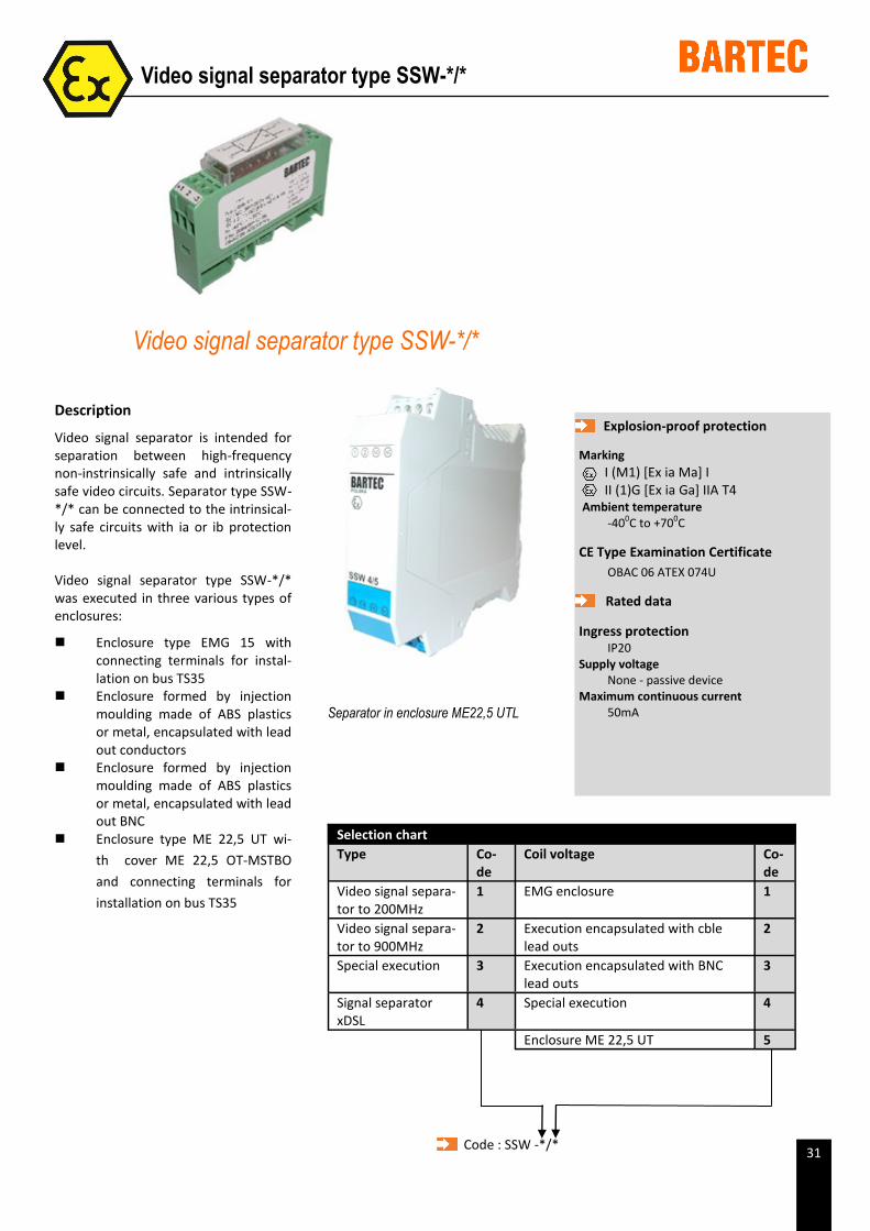
Video signal separator is intended for separation between high-frequency non-instrinsically safe and intrinsically safe video circuits. Separator type SSW-*/* can be connected to the intrinsical-ly safe circuits with ia or ib protection level.
Video signal separator type SSW-*/* was executed in three various types of enclosures:
Enclosure type EMG 15 with connecting terminals for instal-lation on bus TS35
Enclosure formed by injection moulding made of ABS plastics or metal, encapsulated with lead out conductors
Enclosure formed by injection moulding made of ABS plastics or metal, encapsulated with lead out BNC
Enclosure type ME 22,5 UT wi-
th cover ME 22,5 OT-MSTBO
and connecting terminals for
installation on bus TS35
Video signal separator type SSW-*/*
Video signal separator type SSW-*/*
Explosion-proof protection
Marking
I (M1) [Ex ia Ma] I II (1)G [Ex ia Ga] IIA T4
Ambient temperature -400C to +700C
CE Type Examination Certificate
OBAC 06 ATEX 074U
Rated data
Ingress protection IP20
Supply voltage None - passive device
Maximum continuous current 50mA Separator in enclosure ME22,5 UTL
Selection chart
Type Co-de
Coil voltage Co-de
Video signal separa-tor to 200MHz
1 EMG enclosure 1
Video signal separa-tor to 900MHz
2 Execution encapsulated with cble lead outs
2
Special execution 3 Execution encapsulated with BNC lead outs
3
Signal separator xDSL
4 Special execution 4
Enclosure ME 22,5 UT 5
Code : SSW -*/*
33
Description
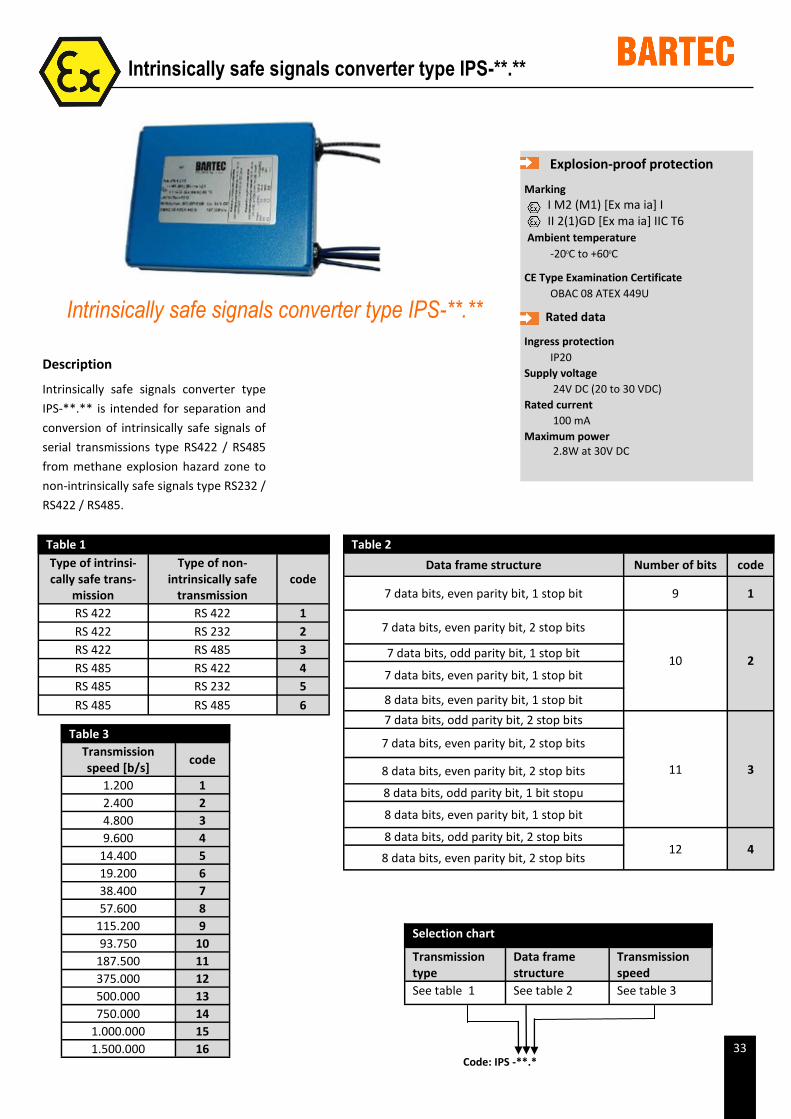
Intrinsically safe signals converter type
IPS-**.** is intended for separation and
conversion of intrinsically safe signals of
serial transmissions type RS422 / RS485
from methane explosion hazard zone to
non-intrinsically safe signals type RS232 /
RS422 / RS485.
Explosion-proof protection
Marking I M2 (M1) [Ex ma ia] I II 2(1)GD [Ex ma ia] IIC T6
Ambient temperature -200C to +600C
CE Type Examination Certificate OBAC 08 ATEX 449U
Rated data
Ingress protection IP20
Supply voltage 24V DC (20 to 30 VDC)
Rated current 100 mA
Maximum power 2.8W at 30V DC
Intrinsically safe signals converter type IPS-**.**
Intrinsically safe signals converter type IPS-**.**
Table 1
Type of intrinsi-cally safe trans-
mission
Type of non-intrinsically safe
transmission code
RS 422 RS 422 1
RS 422 RS 232 2
RS 422 RS 485 3
RS 485 RS 422 4
RS 485 RS 232 5
RS 485 RS 485 6
Table 2
Data frame structure Number of bits code
7 data bits, even parity bit, 1 stop bit 9 1
7 data bits, even parity bit, 2 stop bits
10 2 7 data bits, odd parity bit, 1 stop bit
7 data bits, even parity bit, 1 stop bit
8 data bits, even parity bit, 1 stop bit
7 data bits, odd parity bit, 2 stop bits
11 3
7 data bits, even parity bit, 2 stop bits
8 data bits, even parity bit, 2 stop bits
8 data bits, odd parity bit, 1 bit stopu
8 data bits, even parity bit, 1 stop bit
8 data bits, odd parity bit, 2 stop bits 12 4
8 data bits, even parity bit, 2 stop bits
Table 3
Transmission speed [b/s]
code
1.200 1
2.400 2
4.800 3
9.600 4
14.400 5
19.200 6
38.400 7
57.600 8
115.200 9
93.750 10
187.500 11
375.000 12
500.000 13
750.000 14
1.000.000 15
1.500.000 16
Selection chart
Transmission type
Data frame structure
Transmission speed
See table 1 See table 2 See table 3
Code: IPS -**.*
34
Description
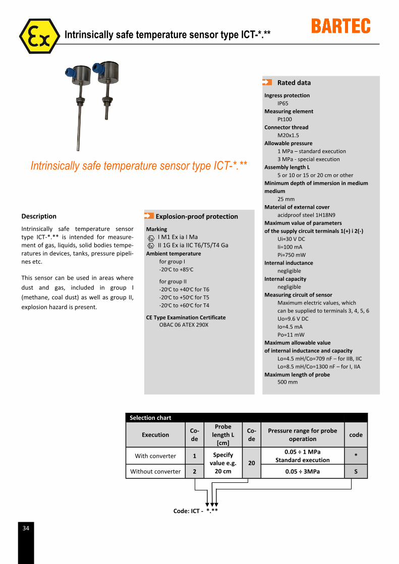
Intrinsically safe temperature sensor type ICT-*.** is intended for measure-ment of gas, liquids, solid bodies tempe-ratures in devices, tanks, pressure pipeli-nes etc.
This sensor can be used in areas where
dust and gas, included in group I
(methane, coal dust) as well as group II,
explosion hazard is present.
Rated data
Ingress protection IP65
Measuring element Pt100
Connector thread M20x1.5
Allowable pressure 1 MPa – standard execution 3 MPa - special execution
Assembly length L 5 or 10 or 15 or 20 cm or other
Minimum depth of immersion in medium medium
25 mm Material of external cover
acidproof steel 1H18N9 Maximum value of parameters of the supply circuit terminals 1(+) i 2(-)
Ui=30 V DC Ii=100 mA Pi=750 mW
Internal inductance negligible
Internal capacity negligible
Measuring circuit of sensor Maximum electric values, which can be supplied to terminals 3, 4, 5, 6 Uo=9.6 V DC Io=4.5 mA Po=11 mW
Maximum allowable value of internal inductance and capacity
Lo=4.5 mH/Co=709 nF – for IIB, IIC Lo=8.5 mH/Co=1300 nF – for I, IIA
Maximum length of probe 500 mm
Intrinsically safe temperature sensor type ICT-*.**
Intrinsically safe temperature sensor type ICT-*.**
Explosion-proof protection
Marking I M1 Ex ia I Ma II 1G Ex ia IIC T6/T5/T4 Ga
Ambient temperature for group I
-200C to +850C
for group II
-200C to +400C for T6
-200C to +500C for T5
-200C to +600C for T4
CE Type Examination Certificate OBAC 06 ATEX 290X
Code: ICT - *.**
Selection chart
Execution Co-de
Probe length L
[cm]
Co-de
Pressure range for probe operation
code
With converter 1 Specify value e.g.
20 cm 20
0.05 ÷ 1 MPa Standard execution
*
Without converter 2 0.05 ÷ 3MPa S
35
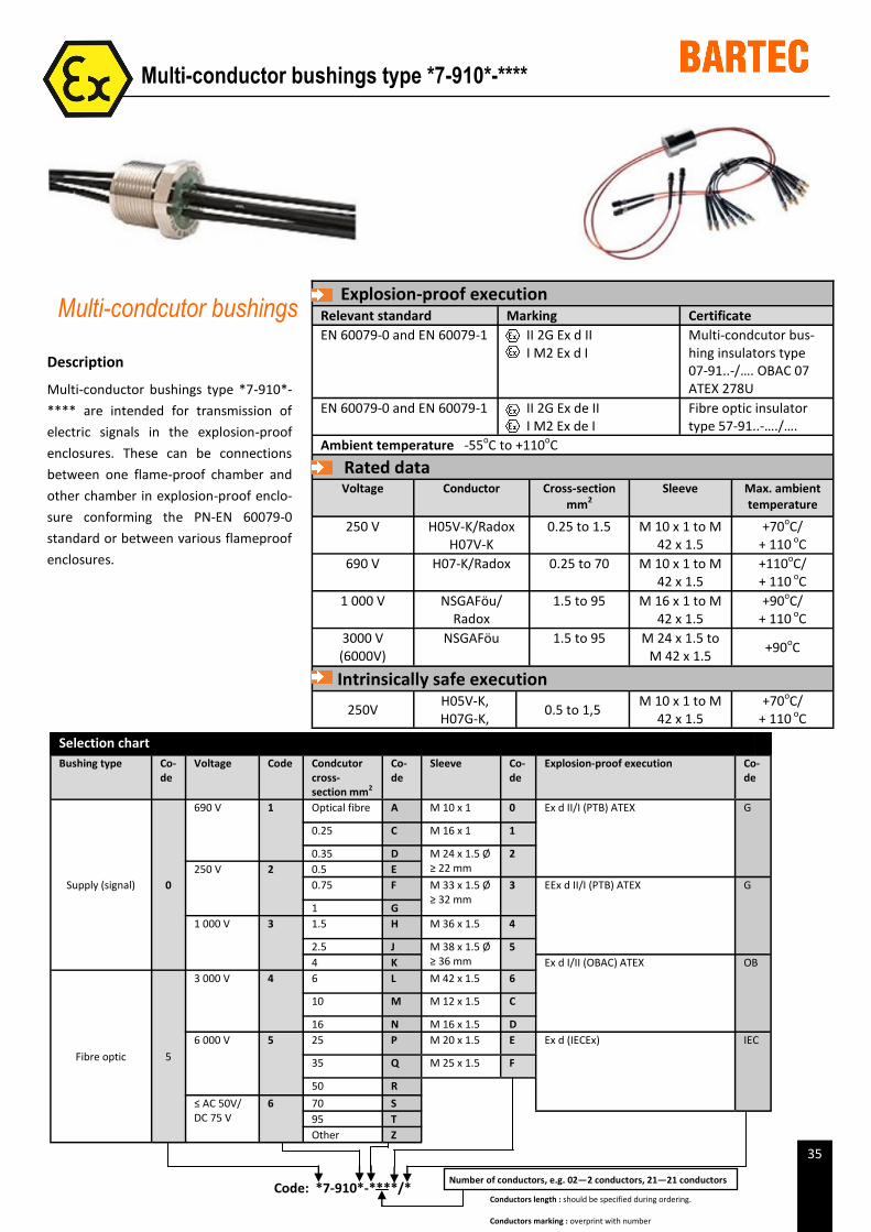
Description
Multi-conductor bushings type *7-910*-
**** are intended for transmission of
electric signals in the explosion-proof
enclosures. These can be connections
between one flame-proof chamber and
other chamber in explosion-proof enclo-
sure conforming the PN-EN 60079-0
standard or between various flameproof
enclosures.
Multi-condcutor bushings
Multi-conductor bushings type *7-910*-****
Code: *7-910*-****/*
Selection chart Bushing type Co-
de Voltage Code Condcutor
cross-section mm2
Co-de
Sleeve Co-de
Explosion-proof execution Co-de
Supply (signal) 0
690 V 1 Optical fibre A M 10 x 1 0 Ex d II/I (PTB) ATEX G
0.25 C M 16 x 1 1
0.35 D M 24 x 1.5 Ø ≥ 22 mm
2
250 V 2 0.5 E
0.75 F M 33 x 1.5 Ø ≥ 32 mm
3 EEx d II/I (PTB) ATEX G
1 G
1 000 V 3 1.5 H M 36 x 1.5 4
2.5 J M 38 x 1.5 Ø ≥ 36 mm
5
4 K Ex d I/II (OBAC) ATEX OB
Fibre optic 5
3 000 V 4 6 L M 42 x 1.5 6
10 M M 12 x 1.5 C
16 N M 16 x 1.5 D
6 000 V 5 25 P M 20 x 1.5 E Ex d (IECEx) IEC
35 Q M 25 x 1.5 F
50 R
≤ AC 50V/ DC 75 V
6 70 S
95 T
Other Z
Number of conductors, e.g. 02—2 conductors, 21—21 conductors
Explosion-proof execution
Relevant standard Marking Certificate
EN 60079-0 and EN 60079-1 II 2G Ex d II I M2 Ex d I
Multi-condcutor bus-hing insulators type 07-91..-/…. OBAC 07 ATEX 278U
EN 60079-0 and EN 60079-1 II 2G Ex de II I M2 Ex de I
Fibre optic insulator type 57-91..-…./….
Ambient temperature -55oC to +110oC
Rated data
Voltage Conductor Cross-section mm2
Sleeve Max. ambient temperature
250 V H05V-K/Radox H07V-K
0.25 to 1.5 M 10 x 1 to M 42 x 1.5
+70oC/ + 110 oC
690 V H07-K/Radox 0.25 to 70 M 10 x 1 to M 42 x 1.5
+110oC/ + 110 oC
1 000 V NSGAFöu/Radox
1.5 to 95 M 16 x 1 to M 42 x 1.5
+90oC/ + 110 oC
3000 V (6000V)
NSGAFöu 1.5 to 95 M 24 x 1.5 to M 42 x 1.5
+90oC
Intrinsically safe execution
250V H05V-K, H07G-K,
0.5 to 1,5 M 10 x 1 to M
42 x 1.5 +70oC/
+ 110 oC
Conductors length : should be specified during ordering.
Conductors marking : overprint with number