safe peratio ractices t-up peratio rvice roublesooing ... · pdf filesafe peratio ractices...
TRANSCRIPT

Printed In USA
Safe Operation Practices • Set-Up • Operation • Service • Troubleshooting
WARNINGREAD AND FOLLOW ALL SAFETY RULES AND INSTRUCTIONS IN THIS MANUAL
BEFORE ATTEMPTING TO OPERATE THIS MACHINE. FAILURE TO COMPLY WITH THESE INSTRUCTIONS MAY RESULT IN PERSONAL INJURY.
OperatOr’s Manual
Form No. 769-10790 (May 20, 2015)
Safe Operation Practices ........................................ 2Assembly & Set-Up .................................................. 5Controls & Operation .............................................. 8
Service .....................................................................10Troubleshooting .....................................................12Parts/Warranty .............. See Separate Supplement
Table of Contents
NOTE: This Operator’s Manual covers several models. Features may vary by model. Not all features in this manual are applicable to all models and the model depicted may differ from yours.
Snow Thrower
Single-Stage (200 Series)

2
Important Safe Operation Practices 1
Training1. Read, understand, and follow all instructions on the machine and
in the manual(s) before attempting to assemble and operate. Keep this manual in a safe place for future and regular reference and for ordering replacement parts.
2. Be familiar with all controls and their proper operation. Know how to stop the machine and disengage them quickly.
3. Never allow children under 14 years of age to operate this machine. Children 14 and over should read and understand the instructions and safe operation practices in this manual and on the machine and be trained and supervised by an adult.
4. Never allow adults to operate this machine without proper instruction.
5. Thrown objects can cause serious personal injury. Plan your snow-throwing pattern to avoid discharge of material toward roads, bystanders and the like.
6. Keep bystanders, pets and children at least 75 feet from the machine while it is in operation. Stop machine if anyone enters the area.
7. Exercise caution to avoid slipping or falling, especially when operating in reverse.
Preparation1. Thoroughly inspect the area where the equipment is to be used.
Remove all doormats, newspapers, sleds, boards, wires and other foreign objects, which could be tripped over or thrown by the auger.
2. Always wear safety glasses or eye shields during operation and while performing an adjustment or repair to protect your eyes. Thrown objects which ricochet can cause serious injury to the eyes.
3. Do not operate without wearing adequate winter outer garments. Do not wear jewelry, long scarves or other loose clothing, which could become entangled in moving parts. Wear footwear which will improve footing on slippery surfaces.
4. Use a grounded three-wire extension cord and receptacle for all machines with electric start engines.
5. Disengage all control levers before starting the engine.
6. Never attempt to make any adjustments while engine is running, except where specifically recommended in the operator’s manual.
7. Let engine and machine adjust to outdoor temperature before starting to clear snow.
Safe Handling of GasolineTo avoid personal injury or property damage use extreme care in handling gasoline. Gasoline is extremely flammable and the vapors are explosive. Serious personal injury can occur when gasoline is spilled on yourself or your clothes which can ignite. Wash your skin and change clothes immediately.
1. Use only an approved gasoline container.
2. Extinguish all cigarettes, cigars, pipes and other sources of ignition.
3. Never fuel machine indoors.
4. Never remove gas cap or add fuel while the engine is hot or running.
5. Allow engine to cool at least two minutes before refueling.
6. Never over fill fuel tank. Fill tank to no more than ½” below bottom of filler neck to provide space for fuel expansion.
7. Replace gasoline cap and tighten securely.
8. If gasoline is spilled, wipe it off the engine and equipment. Move machine to another area. Wait 5 minutes before starting the engine.
9. Never store the machine or fuel container inside where there is an open flame, spark or pilot light (e.g. furnace, water heater, space heater, clothes dryer etc.).
10. Allow machine to cool at least 5 minutes before storing.
11. Never fill containers inside a vehicle or on a truck or trailer bed with a plastic liner. Always place containers on the ground away from your vehicle before filling.
12. If possible, remove gas-powered equipment from the truck or trailer and refuel it on the ground. If this is not possible, then refuel such equipment on a trailer with a portable container, rather than from a gasoline dispenser nozzle.
13. Keep the nozzle in contact with the rim of the fuel tank or container opening at all times until fueling is complete. Do not use a nozzle lock-open device.
Operation1. Do not put hands or feet near rotating parts, in the auger housing
or chute assembly. Contact with the rotating parts can amputate hands and feet.
2. The auger control lever is a safety device. Never bypass its operation. Doing so makes the machine unsafe and may cause personal injury.
3. The control levers must operate easily in both directions and automatically return to the disengaged position when released.
4. Never operate with a missing or damaged chute assembly. Keep all safety devices in place and working.
5. Never run an engine indoors or in a poorly ventilated area. Engine exhaust contains carbon monoxide, an odorless and deadly gas.
6. Do not operate machine while under the influence of alcohol or drugs.
7. Muffler and engine become hot and can cause a burn. Do not touch. Keep children away.
8. Do not operate on gravel or crushed rock surfaces. If crossing, make sure auger is off and use extreme caution. Stay alert for hidden hazards or traffic.
9. Exercise caution when changing direction and while operating on slopes. Do not operate on steep slopes.
WARNING! This symbol points out important safety instructions which, if not followed, could endanger the personal safety and/or property of yourself and others. Read and follow all instructions in this manual before attempting to operate this machine. Failure to comply with these instructions may result in personal injury. When you see this symbol. HEED ITS WARNING!
CALIFORNIA PROPOSITION 65
WARNING! Engine Exhaust, some of its constituents, and certain vehicle components contain or emit chemicals known to State of California to cause cancer and birth defects or other reproductive harm.
DANGER: This machine was built to be operated according to the safe operation practices in this manual. As with any type of power equipment, carelessness or error on the part of the operator can result in serious injury. This machine is capable of amputating fingers, hands, toes and feet and throwing foreign objects. Failure to observe the following safety instructions could result in serious injury or death.

3Section 2 — important Safe operation practiceS
10. Plan your snow-throwing pattern to avoid discharge towards windows, walls, cars etc. Thus, avoiding possible property damage or personal injury caused by a ricochet.
11. Never direct discharge at children, bystanders and pets or allow anyone in front of the machine.
12. Do not overload machine capacity by attempting to clear snow at too fast of a rate.
13. Never operate this machine without good visibility or light. Always be sure of your footing and keep a firm hold on the handles. Walk, never run.
14. Disengage power to the auger when transporting or not clearing snow.
15. Never operate machine at high transport speeds on slippery surfaces. Look down and behind and use care when backing up.
16. If the machine should start to vibrate abnormally, stop the engine, disconnect the spark plug wire and ground it against the engine. Inspect thoroughly for damage. Repair any damage before starting and operating.
17. Disengage all control levers and stop engine before you leave the operating position (behind the handles). Wait until the auger comes to a complete stop before unclogging the chute assembly, making any adjustments, or inspections.
18. Never put your hand in the discharge or collector openings. Do not unclog chute assembly while engine is running. Shut off engine and remain behind handles until all moving parts have stopped before unclogging.
19. Use only attachments and accessories approved by the manufacturer (e.g. wheel weights, tire chains, cabs etc.).
20. When starting engine, pull cord slowly until resistance is felt, then pull rapidly. Rapid retraction of starter cord (kickback) will pull hand and arm toward engine faster than you can let go. Broken bones, fractures, bruises or sprains could result.
21. If situations occur which are not covered in this manual, use care and good judgment. Contact Customer Support for assistance and the name of your nearest servicing dealer.
Clearing a Clogged Discharge ChuteHand contact with the rotating auger inside the discharge chute is the most common cause of injury associated with snow throwers. Never use your hand to clean out the discharge chute.
To clear the chute:
1. SHUT THE ENGINE OFF!
2. Wait 10 seconds to be sure the auger blades have stopped rotating.
3. Always use a clean-out tool, not your hands.
Maintenance & Storage1. Never tamper with safety devices. Check their proper operation
regularly. Refer to the maintenance and adjustment sections of this manual.
2. Before cleaning, repairing, or inspecting machine disengage all control levers and stop the engine. Wait until the auger come to a complete stop. Disconnect the spark plug wire and ground against the engine to prevent unintended starting.
3. Check bolts and screws for proper tightness at frequent intervals to keep the machine in safe working condition. Also, visually inspect machine for any damage.
4. Do not change the engine governor setting or over-speed the engine. The governor controls the maximum safe operating speed of the engine
5. Snow thrower shave plates and skid shoes are subject to wear and damage. For your safety protection, frequently check all components and replace with original equipment manufacturer’s (OEM) parts only. “Use of parts which do not meet the original equipment specifications may lead to improper performance and compromise safety!”
6. Check control levers periodically to verify they engage and disengage properly and adjust, if necessary. Refer to the adjustment section in this operator’s manual for instructions.
7. Maintain or replace safety and instruction labels, as necessary.
8. Observe proper disposal laws and regulations for gas, oil, etc. to protect the environment.
9. Prior to storing, run machine a few minutes to clear snow from machine and prevent freeze up of auger.
10. Never store the machine or fuel container inside where there is an open flame, spark or pilot light such as a water heater, furnace, clothes dryer, etc.
11. Always refer to the operator’s manual for proper instructions on off-season storage.
12. Check fuel line, tank, cap, and fittings frequently for cracks or leaks. Replace if necessary.
13. Do not crank engine with spark plug removed.
14. According to the Consumer Products Safety Commission (CPSC) and the U.S. Environmental Protection Agency (EPA), this product has an Average Useful Life of seven (7) years, or 60 hours of operation. At the end of the Average Useful Life have the machine inspected annually by an authorized service dealer to ensure that all mechanical and safety systems are working properly and not worn excessively. Failure to do so can result in accidents, injuries or death.
Do not modify engineTo avoid serious injury or death, do not modify engine in any way. Tampering with the governor setting can lead to a runaway engine and cause it to operate at unsafe speeds. Never tamper with factory setting of engine governor.
Notice Regarding EmissionsEngines which are certified to comply with California and federal EPA emission regulations for SORE (Small Off Road Equipment) are certified to operate on regular unleaded gasoline, and may include the following emission control systems: Engine Modification (EM), Oxidizing Catalyst (OC), Secondary Air Injection (SAI) and Three Way Catalyst (TWC) if so equipped.

4 Section 2 — important Safe operation practiceS
Safety SymbolsThis page depicts and describes safety symbols that may appear on this product. Read, understand, and follow all instructions on the machine before attempting to assemble and operate.
Symbol Description
READ THE OPERATOR’S MANUAL(S) Read, understand, and follow all instructions in the manual(s) before attempting to assemble and operate.
WARNING — ROTATING BLADES Keep hands out of inlet and discharge openings while machine is running. There are rotating blades inside.
WARNING — ROTATING BLADES Keep hands out of inlet and discharge openings while machine is running. There are rotating blades inside.
WARNING — ROTATING AUGER Do not put hands or feet near rotating parts, in the auger housing or chute assembly. Contact with the rotating parts can amputate hands and feet.
WARNING — THROWN OBJECTS This machine may pick up and throw objects which can cause serious personal injury.
WARNING — GASOLINE IS FLAMMABLE Allow the engine to cool at least two minutes before refueling.
WARNING — CARBON MONOXIDENever run an engine indoors or in a poorly ventilated area. Engine exhaust contains carbon monoxide, an odorless and deadly gas.
WARNING — ELECTRICAL SHOCK Do not use the engine’s electric starter in the rain.
WARNING — HOT SURFACE Engine parts, especially the muffler, become extremely hot during operation. Allow engine and muffler to cool before touching.
WARNING! Your Responsibility — Restrict the use of this power machine to persons who read, understand and follow the warnings and instructions in this manual and on the machine.
SAVE THESE INSTRUCTIONS!

Assembly & Set-Up 2
5
Upper 2-Way Chute Lower 2-Way Chute E-Z Chute™
Chute Plug Chute Plug
Chute RotationControl Assembly
Chute RotationControl Assembly
ChuteChuteChute
Chute Handle
Page 6Page 6 Page 6
Figure 2-1
NOTE: This Operator’s Manual covers several models. Features may vary by model. Not all features in this manual are applicable to all models and the model depicted may differ from yours. Refer to Figure 2-1 to match your chute style.
Thank you for purchasing this product. It was carefully engineered to provide excellent performance when properly operated and maintained.
Please read this entire manual prior to operating the equipment. It instructs you how to safely and easily set up, operate and maintain your machine. Please be sure that you, and any other persons who will operate the machine, carefully follow the recommended safety practices at all times. Failure to do so could result in personal injury or property damage.
All information in this manual is relative to the most recent product information available at the time. Review this manual frequently to familiarize yourself with the machine, its features and operation. Please be aware that this Operator’s Manual may cover a range of product specifications for various models. Characteristics and features discussed and/or illustrated in this manual may not be applicable to all models. We reserve the right to change product specifications, designs and equipment without notice and without incurring obligation.
If applicable, the power testing information used to establish the power rating of the engine equipped on this machine can be found at www.opei.org or the engine manufacturer’s web site.
If you have any problems or questions concerning the machine, phone your local authorized service dealer or contact us directly. We want to ensure your complete satisfaction at all times.
Throughout this manual, all references to right and left side of the machine are observed from the operating position.
Thank You
Contents of Carton• Snow Thrower (1) • Pair Drift Cutters (1) — If equipped • Snow Thrower Operator’s Manual (1)
• Safety Key (2) • 20 oz. Bottle 5W-30 Oil (1) • Engine Operator’s Manual (1)
• Chute Assembly (1) • Product Registration Card (1) • Parts/Warranty Document (1)
• Chute Rotation Control Assembly (1) • Eye Bolt (1) • Handle Knob (1)

6 Section 2 — ASSembly & Set-Up
3. Align the holes in the chute base with the three tabs (b) in the lower chute as shown in Figure 2-8, Inset I. Secure the chute base with the hex washer screws (a) removed in Step 2. See Figure 2-8.
(a)
(a)
(a)
I
(b) (b)(b)
Figure 2-8
STOPSTOP! Continue to Installing the Recoil Starter Handle onto the Upper Handle (page 7).
Lower 2-Way Chute & Upper 2-Way Chute1. If not already done, install the chute plug (a)
onto the chute (b) as shown in Figure 2-9. Be certain that the plug is aligned in the channel on the chute and that the tabs snap into place.
(a)(b)
Figure 2-9
2. Remove the hex washer screws (a) in the chute base. See Figure 2-7.
3. Align the holes in the chute base with the three tabs (b) in the lower chute as shown in Figure 2-8, Inset I. Secure the chute base with the hex washer screws (a) removed in Step 2. See Figure 2-8.
STOPSTOP! Continue to Installing the Chute Rotation Control (page 7).
4. On models with adjustable handles, place the handle in the desired position and then install wing knobs (a) and carriage bolts (b) in the appropriate hole and secure the handle. See Figure 2-5.
(a)
(b)
Figure 2-5
Chute Assembly OptionsNOTE: Refer to Figure 2-1 and continue to your applicable chute style on pages 6-7.
E-Z Chute™1. Place the chute handle (a) onto the
chute (b) as shown in Figure 2-6. Be certain that the handle is aligned in the channel on the chute and the tabs snap into place.
(a)
(a)
(b)
(b)
Figure 2-6
2. Remove the hex washer screws (a) in the chute base. See Figure 2-7.
(a)(a)
(a)
Figure 2-7
Tools Required• Adjustable Wrench or Socket Set
• Phillips Head Screwdriver
Handle Assembly1. Remove the wing knob (a) and carriage
bolt (b) from the top of the lower handle. See Figure 2-2. It is not necessary to remove the shoulder screw and flange lock nut below the wing knob and carriage bolt unless the handle is loose in the carton.
(a)(b)
(a)(b)
Figure 2-2
2. Pivot the upper handle into the operating position. Be sure not to pinch any of the cables in the process. See Figure 2-3.
(a)
(a)
(b)(b)
Figure 2-3
3. See Figure 2-4. On models with an adjustable handle (a), proceed with Step 4. On models without adjustable handle (b), tighten the hardware removed in Step 1 to secure the handle in place. See Figure 2-3. For models without an adjustable handle (b), continue to Installing the Chute.
(b)(a)
AdjustableHandle
Non-AdjustableHandle
Figure 2-4

7Section 2 — ASSembly & Set-Up
2. Using the hex washer screws (a), install the chute rotation control assembly. See Figure 2-12.
(a)
(a)
(a)(a)
Figure 2-12
3. Remove the screw (a) and hex lock nut (b) from the universal joint. See Figure 2-13.
(a)
(b)
Figure 2-13
NOTE: Make sure the chute is facing forward when installing the universal joint.
4. Install the universal joint on the end of the chute rod as shown in Figure 2-13.
NOTE: Be sure the holes in the universal joint line up with the holes in the chute rod. You may have to activate the trigger to allow you to line up the holes.
5. Secure the universal joint with the hex lock nut (b) and screw (a) removed in Step 3. See Figure 2-13.
6. Slide the rubber bellow over the universal joint. See Figure 2-14.
Figure 2-14
STOPSTOP! Continue to Installing the Recoil Starter Handle onto the Upper Handle (page 7).
Installing the Chute Rotation Control (If Equipped)NOTE: Refer to Figure 2-1 and continue to your applicable chute style.
Lower 2-Way Chute1. Remove the hex lock nut (a) and machine
screw (b) from the chute rotation control assembly. See Inset I in Figure 2-10.
(a)
(a)
(b)
(b)
I
II
Figure 2-10
2. Place the chute rotation control assembly onto the chute rotation rod, align the holes and secure with the hex lock nut (a) and machine screw (b) removed in Step 1. See Inset II in Figure 2-10.
STOPSTOP! Continue to Installing the Recoil Starter Handle onto the Upper Handle (page 7).
Upper 2-Way Chute1. Remove the hex washer screws (a) from
the back of the handle (two on each side). See Figure 2-11.
(a)
(a) (a)
(a)
Figure 2-11
Installing the Recoil Starter Handle onto the Upper Handle1. Remove the eye bolt and handle knob
from the manual bag.
2. Place the eye bolt (a) and handle knob (b) on the upper handle as shown in Inset I in Figure 2-15. Do not fully tighten the hardware until instructed to do so.
(b)
(a)I
II
Figure 2-15
NOTE: The opening of the eye bolt (a) should face toward the back of the snow thrower.
3. Slowly pull the recoil starter handle up towards the eye bolt (a).
4. Slip the recoil starter rope into the eye bolt (a) from the back of the snow thrower. See Inset II in Figure 2-15.
5. Securely tighten the eye bolt (a) and handle knob (b).
Installing the Drift Cutters (If Equipped)1. Remove the carriage bolts (a) and flange
lock nuts (b) from the drift cutters.
2. Install the drift cutters and secure with the carriage bolts (a) and flange lock nuts (b) removed in Step 1. See Figure 2-16.
(b) (a)
Figure 2-16
Adding Fuel & OilRefer to the Engine Operator’s Manual for information on adding fuel and oil.

Controls & Operation 3
8
Headlight (If Equipped)The headlight is located on the upper center of the control panel and is ON when the snow thrower is running.
Engine ControlsIf your model has an electric starter, stand in the operator’s position and refer to Figure 3-2 for the location of the Engine Controls. If your model does not have an electric starter, stand in the operator’s position and refer to Figure 3-3 for the location of the Engine Controls.
Choke Lever
Primer Safety Key
Electric StarterOutlet †
† — If Equipped
Electric StarterButton †
Figure 3-2
Choke Lever
PrimerSafety Key
Figure 3-3
Snow thrower controls and features are described below and illustrated in Figure 3-1.
NOTE: This Operator’s Manual covers several models. Snow thrower features may vary by model. Not all features in this manual are applicable to all snow thrower models and the snow thrower depicted may differ from yours.
NOTE: All references to the left or right side of the snow thrower are from the operator’s position. Any exceptions will be noted.
AugerWhen engaged, the auger rotation draws snow into the auger housing and throws it out the chute assembly. Rubber paddles on the auger also aid in propelling the snow thrower as they come in contact with the pavement.
Auger Control LeverLocated on the upper handle, the auger control lever is used to engage and disengage drive to the auger. Squeeze the auger control lever against the upper handle to engage the auger; release it to disengage.
Shave PlateThe shave plate maintains contact with the pavement as the snow thrower is propelled, allowing snow close to the pavement’s surface to be discharged.
Recoil Starter HandleThe recoil starter handle is used to manually start the engine.
Chute Assembly(See Insets for Specific
Chute Types)
Recoil Starter Handle
Auger
Auger Control LeverHeadlight †Chute Tilt Control †
Chute Rotation Control †
Shave Plate
Drift Cutter †
ChuteHandle †
Lower 2-Way Chute †
Chute Rotation Control
Upper 2-Way Chute †
Chute Assembly
Chute Tilt Control
Chute Rotation Control
E-Z Chute™ †
Figure 3-1
E-Z Chute™ (If Equipped)Rotate the chute assembly to the left or right using the chute handle. The pitch of the chute assembly controls the angle at which the snow is thrown. Stop the engine, remove the safety key and loosen the wing knob on the side of the chute assembly before pivoting the upper portion of the chute assembly upward or downward. Retighten the knob once the desired position has been achieved.
Lower 2-Way Chute (If Equipped)Rotate the chute assembly to the left or right using the chute rotation control. The pitch of the chute assembly controls the angle at which the snow is thrown. Stop the engine, remove the safety key and loosen the wing knob on the side of the chute assembly before pivoting the chute upward or downward. Retighten the knob once the desired position has been achieved.
Upper 2-Way Chute (If Equipped)
Chute Tilt ControlThe chute tilt control is located to the right of the control panel and controls the angle/distance that snow is thrown. Pull back on the chute tilt control to increase the angle/distance and push forward to decrease the angle/distance.
Chute Rotation ControlThe chute rotation control is located in the center of the control panel and controls the direction snow is thrown. Depress the button and rotate the chute rotation control to the right to turn the chute to the right and rotate to the left to turn the chute to the left.
Drift Cutters (If Equipped)The drift cutters are designed for use in deep snow. Their use is optional for normal snow conditions. Maneuver the snow thrower so that the cutters penetrate a high standing snow drift to assist snow falling into the augers for throwing.
† — If Equipped

9Section 3 — controlS & operation
Engaging the DriveLift up slightly on the handle to allow the rubber paddles on the auger to contact the pavement and propel the snow thrower forward. Pushing downward on the handle will raise the auger off the ground and stop the forward motion.
NOTE: Excessive upward pressure on the handle will result in premature wear on the rubber auger blades which will not be covered by the warranty.
Adjusting the Chute
E-Z Chute™ (If Equipped)Rotate the chute assembly to the left or right using the chute handle (a). See Figure 3-5.
(a)
(c)
(b)
Figure 3-5
To adjust the pitch, stop the engine, remove the safety key and loosen the wing knob (b) on the side of the chute assembly and pivot the upper portion of the chute assembly (c) upward or downward. Retighten the wing knob (b) once the desired position has been achieved. See Figure 3-5.
Lower 2-Way Chute (If Equipped)Rotate the chute assembly to the left or right using the chute rotation control (a). See Figure 3-6.
(a)
(b)
(c)
Figure 3-6
To adjust the pitch, stop the engine, remove the safety key, loosen the wing knob (b) on the side of the chute assembly and pivot the upper portion of the chute assembly (c) upward or downward. Retighten the wing knob (b) once the desired position has been achieved. See Figure 3-6.
Choke LeverActivating the choke control closes the choke plate on carburetor and aids in starting engine. The choke lever slides between the RUN and CHOKE positions.
PrimerPressing the primer, making sure to cover the vent hole when pushing, forces fuel directly into the engine’s carburetor to aid in cold-weather starting.
Safety KeyThe safety key is a safety device. It must be fully inserted in order for the engine to start. Remove the safety key when the snow thrower is not in use.
Electric Starter Outlet (If Equipped)Requires the use of a grounded, three-prong outdoor extension cord and a 120V power source/wall outlet.
Electric Starter Button (If Equipped)Pressing the electric starter button engages the engine’s electric starter when plugged into a 120V power source.
NOTE: Refer to the Engine Operator’s Manual for more information on how to use the Engine Controls.
Starting & Stopping the EngineWARNING! Always keep hands and feet clear of moving parts. Do not use a pressurized starting fluid. Vapors are flammable.
Refer to the Engine Operator’s Manual for instructions on starting and stopping the engine.
Engaging the AugerTo engage the auger and start throwing snow, squeeze the auger control lever against the handle. Release to stop the auger. See Figure 3-4.
Figure 3-4
Upper 2-Way Chute (If Equipped)To increase the angle/distance snow is thrown, pull up/back on the chute tilt control (a). To decrease the angle/distance snow is thrown, push down/forward on the chute tilt control (a). See Figure 3-7.
(a)
(b)
Figure 3-7
To rotate the chute to the left, pull the trigger and turn the chute rotation control (b) to the left. To rotate the chute to the right, pull the trigger and turn the chute rotation control (b) to the right. See Figure 3-7.
Clearing a Clogged Chute AssemblyWARNING! Never use your hands to clear a clogged chute assembly. Shut OFF engine and remain behind handles until all moving parts have stopped before using the clean-out tool to clear the chute assembly.
Hand contact with the rotating auger inside the chute assembly is the most common cause of injury associated with snow throwers. Never use your hand to clean out the chute assembly.
To clear the chute:
1. SHUT THE ENGINE OFF!
2. Wait 10 seconds to be sure the auger blades have stopped rotating.
3. Always use a clean-out tool (Part No. 931-2643), not your hands. Refer to the separate supplement for clean-out tool ordering information.
Service 4
10
4. Tip the snow thrower back to the operating position and pull the recoil starter handle a few times to see if it is difficult to pull.
5. If the recoil starter handle is difficult to pull, remove the spark plug as instructed in your Engine Operator’s Manual and pull the handle several times to ensure that any oil trapped in the head is removed.
CAUTION: Oil may come out of the spark plug hole when it is removed and the recoil starter handle is pulled.
6. Inspect the spark plug as instructed in your Engine Operator’s Manual. If it is wet, clean off any oil before re-installing.
Control CableAs a result of both the control cable and the auger drive belt stretching due to wear, periodic adjustments may be necessary. If the auger seems to hesitate when rotating, proceed as follows:
The upper hole in the auger control lever provides for an adjustment in cable tension. To adjust, disconnect the end of control cable from the bottom hole in the auger control lever and reinsert it in the upper hole. Insert the cable from the outside as shown in Figure 4-3.
Figure 4-3
Test the snow thrower to see if there is a noticeable difference. If after the adjustment to the control cable the auger still hesitates when rotating, replace the belt.
NOTE: When the auger control lever is released, the auger should stop rotating. If the auger continues rotating after the adjustment, contact an authorized service center.
Replacing the Auger Drive Belt1. Run the snow thrower until the fuel tank
is empty.
2. Pull the recoil starter handle until resistance is felt. Then tip the snow thrower back until it rests on the handles.
3. Slide a board up through the auger and through the chute to secure the auger in place.
NOTE: An oil drain extension kit is available separately. Contact your local authorized dealer or contact Customer Support.
3. Change the oil and/or the spark plug as instructed in your Engine Operator’s Manual.
4. Re-install the lower panel by placing the tabs in the tab slots, lifting the panel into place and secure with the three screws removed in Step 2.
5. Tip the snow thrower back to the operating position and pull the recoil starter handle a few times to see if it is difficult to pull.
6. If the recoil starter handle is difficult to pull, remove the spark plug as instructed in your Engine Operator’s Manual and pull the handle several times to ensure that any oil trapped in the head is removed.
CAUTION: Oil may come out of the spark plug hole when it is removed and the recoil starter handle is pulled.
7. Inspect the spark plug. If it is wet, clean off any oil before re-installing.
Adjustments
Shave PlateTo check the adjustment of the shave plate, place the snow thrower on a level surface. The wheels, shave plate and auger should all contact the level surface. Note that if the shave plate is adjusted too high, snow may blow under the housing. If the shave plate wears out excessively, or the snow thrower does not self-propel, the shave plate may be too low and needs to be adjusted.
NOTE: On new snow throwers or machines with a new shave plate installed, the auger may be slightly off the ground.
To adjust the shave plate proceed as follows:
1. Run the snow thrower until the fuel tank is empty.
2. Pull the recoil starter handle until resistance is felt. Then tip the snow thrower back until it rests on the handles.
3. Loosen the four flange lock nuts (a) and carriage screws (b) which secure the shave plate to the housing. See Figure 4-2. Move the shave plate to the desired position and retighten the flange lock nuts (a) and carriage screws (b) securely.
(a)
(b)
Figure 4-2
WARNING! Before servicing, repairing or inspecting the snow thrower, disengage the auger control lever. Stop the engine and remove the safety key to prevent unintended starting.
Maintenance
LubricationLubricate the pivot points on the auger control lever and the extension spring at the end of the control cable with a light oil once every season and before the snow thrower is put into storage at the end of the season.
Off-Season StorageIf the unit will not be used for 30 days or longer, follow the storage instructions below.
1. Run engine until fuel tank is empty and it stops due to lack of fuel. Do not attempt to pour fuel from engine.
2. Lubricate machine as instructed in the Lubrication section.
3. Store in a clean, dry area.
4. If storing unit in an unventilated area, rustproof machine using a light oil or silicone to coat the snow thrower.
5. Clean the exterior of the engine and the snow thrower.
IMPORTANT: When storing unit or when it is not being serviced, it is to remain in the operating position with both wheels and auger housing on the ground.
NOTE: Refer to Engine Operator’s Manual for information on storing your engine.
EngineRefer to the Engine Operator’s Manual for maintenance, service and adjustment information on your engine.
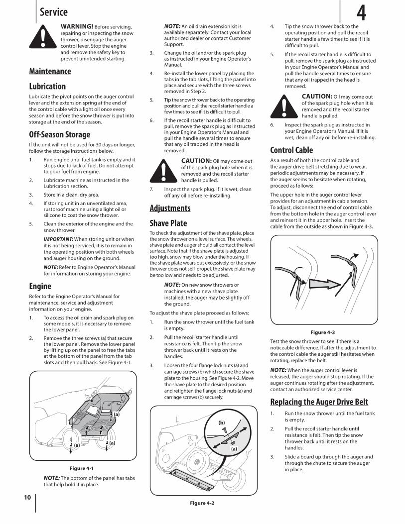
1. To access the oil drain and spark plug on some models, it is necessary to remove the lower panel.
2. Remove the three screws (a) that secure the lower panel. Remove the lower panel by lifting up on the panel to free the tabs at the bottom of the panel from the tab slots and then pull back. See Figure 4-1.
(a)
(a)(a)
Figure 4-1
NOTE: The bottom of the panel has tabs that help hold it in place.
11Section 4 — Service
4. Remove the belt cover by removing the two hex washer screws (a) and one hex lock screw (b) that secure it to the frame. See Figure 4-4.
(b)
(a)
(a)
Figure 4-4
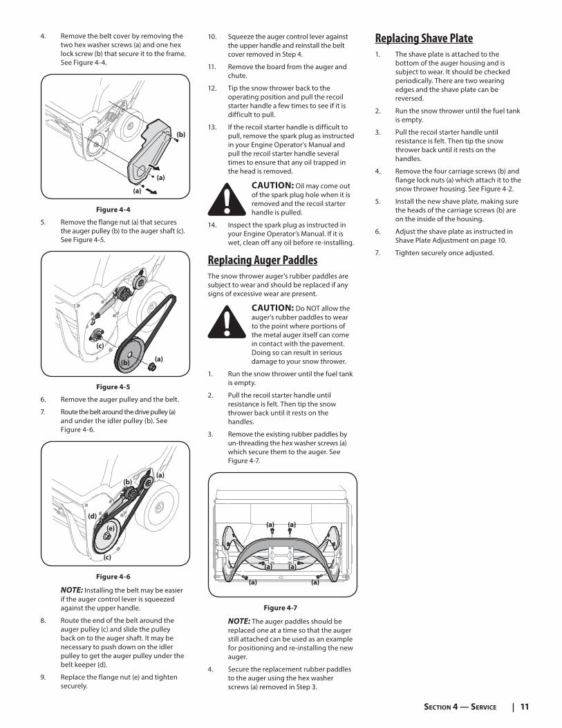
5. Remove the flange nut (a) that secures the auger pulley (b) to the auger shaft (c). See Figure 4-5.
(a)(b)
(c)
Figure 4-5
6. Remove the auger pulley and the belt.
7. Route the belt around the drive pulley (a) and under the idler pulley (b). See Figure 4-6.
(c)
(d)
(b)
(e)
(a)
Figure 4-6
NOTE: Installing the belt may be easier if the auger control lever is squeezed against the upper handle.
8. Route the end of the belt around the auger pulley (c) and slide the pulley back on to the auger shaft. It may be necessary to push down on the idler pulley to get the auger pulley under the belt keeper (d).
9. Replace the flange nut (e) and tighten securely.
10. Squeeze the auger control lever against the upper handle and reinstall the belt cover removed in Step 4.
11. Remove the board from the auger and chute.
12. Tip the snow thrower back to the operating position and pull the recoil starter handle a few times to see if it is difficult to pull.
13. If the recoil starter handle is difficult to pull, remove the spark plug as instructed in your Engine Operator’s Manual and pull the recoil starter handle several times to ensure that any oil trapped in the head is removed.
CAUTION: Oil may come out of the spark plug hole when it is removed and the recoil starter handle is pulled.
14. Inspect the spark plug as instructed in your Engine Operator’s Manual. If it is wet, clean off any oil before re-installing.
Replacing Auger PaddlesThe snow thrower auger’s rubber paddles are subject to wear and should be replaced if any signs of excessive wear are present.
CAUTION: Do NOT allow the auger’s rubber paddles to wear to the point where portions of the metal auger itself can come in contact with the pavement. Doing so can result in serious damage to your snow thrower.
1. Run the snow thrower until the fuel tank is empty.
2. Pull the recoil starter handle until resistance is felt. Then tip the snow thrower back until it rests on the handles.
3. Remove the existing rubber paddles by un-threading the hex washer screws (a) which secure them to the auger. See Figure 4-7.
(a)
(a)
(a)
(a)
(a)
(a)
Figure 4-7
NOTE: The auger paddles should be replaced one at a time so that the auger still attached can be used as an example for positioning and re-installing the new auger.
4. Secure the replacement rubber paddles to the auger using the hex washer screws (a) removed in Step 3.
Replacing Shave Plate1. The shave plate is attached to the
bottom of the auger housing and is subject to wear. It should be checked periodically. There are two wearing edges and the shave plate can be reversed.
2. Run the snow thrower until the fuel tank is empty.
3. Pull the recoil starter handle until resistance is felt. Then tip the snow thrower back until it rests on the handles.
4. Remove the four carriage screws (b) and flange lock nuts (a) which attach it to the snow thrower housing. See Figure 4-2.
5. Install the new shave plate, making sure the heads of the carriage screws (b) are on the inside of the housing.
6. Adjust the shave plate as instructed in Shave Plate Adjustment on page 10.
7. Tighten securely once adjusted.
Troubleshooting 5
12
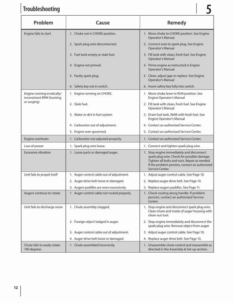
Problem Cause Remedy
Engine fails to start 1. Choke not in CHOKE position.
2. Spark plug wire disconnected.
3. Fuel tank empty or stale fuel.
4. Engine not primed.
5. Faulty spark plug.
6. Safety key not in switch.
1. Move choke to CHOKE position. See Engine Operator’s Manual.
2. Connect wire to spark plug. See Engine Operator’s Manual
3. Fill tank with clean, fresh fuel. See Engine Operator’s Manual
4. Prime engine as instructed in Engine Operator’s Manual.
5. Clean, adjust gap or replace. See Engine Operator’s Manual
6. Insert safety key fully into switch.
Engine running erratically/inconsistent RPM (hunting or surging)
1. Engine running on CHOKE.
2. Stale fuel.
3. Water or dirt in fuel system.
4. Carburetor out of adjustment.
5. Engine over-governed.
1. Move choke lever to RUN position. See Engine Operator’s Manual
2. Fill tank with clean, fresh fuel. See Engine Operator’s Manual
3. Drain fuel tank. Refill with fresh fuel. See Engine Operator’s Manual
4. Contact an authorized Service Center.
5. Contact an authorized Service Center.
Engine overheats 1. Carburetor not adjusted properly. 1. Contact an authorized Service Center.
Loss of power 1. Spark plug wire loose. 1. Connect and tighten spark plug wire.
Excessive vibration 1. Loose parts or damaged auger. 1. Stop engine immediately and disconnect spark plug wire. Check for possible damage. Tighten all bolts and nuts. Repair as needed. If the problem persists, contact an authorized Service Center.
Unit fails to propel itself 1. Auger control cable out of adjustment.
2. Auger drive belt loose or damaged.
3. Augers paddles are worn excessively.
1. Adjust auger control cable. See Page 10.
2. Replace auger drive belt. See Page 10.
3. Replace augers paddles. See Page 11.
Augers continue to rotate 1. Auger control cable not routed properly. 1. Check routing along handle. If problem persists, contact an authorized Service Center.
Unit fails to discharge snow 1. Chute assembly clogged.
2. Foreign object lodged in auger.
3. Auger control cable out of adjustment.
4. Auger drive belt loose or damaged.
1. Stop engine and disconnect spark plug wire. Clean chute and inside of auger housing with clean-out tool.
2. Stop engine immediately and disconnect the spark plug wire. Remove object from auger.
3. Adjust auger control cable. See Page 10.
4. Replace auger drive belt. See Page 10.
Chute fails to easily rotate 190 degrees
1. Chute assembled incorrectly. 1. Unassemble chute control and reassemble as directed in the Assembly & Set-up section.