,s#502y:1 rias - apps.dtic.mil · solution, found that stress-corrosion cracking occurred at strain...
TRANSCRIPT

,S#502y:1
RIAS
TECHNICAL REPORT
ON THE MECHANISM(S) OF65-7
STRESS-CORROSION CRACKING
AUGUST 1965
C L F A R I N• 40U;.
FOR I, :.r-fN'TI .i
. '. .ý l <' "' , , B y!-3 d ,,, '. ') ic• ---I
9. E.N. PUGH
SEt 16 19(5
.7 ,,N

ON TIE MECHANISM4(S) OF STRESS-CORROSION CRACKING
by
E. N. Pugh
First Technical Report to A.R.O.(D)
Army Research Office (Durham) Project
DA-31-124-ARO-D-258
August 1965
Reproduction in whole or in part is permitted for anypurpose of the United States Government
Research Institute for Advanced Studies(Martin Co.)
14,0 S. Rolling RoadB&altimore, Maryland 21227

ABSTRACT
A critical review has been made of some of the major theories of
stress-corrosion cracking, with particular reference to the long-standing
question of whether a single, generalized mechanism exists. It is con-
cluded, largely on the basis of recent studies of a-brass and of aged
aluminum alloys, that several different mechanisms are in fact operative
in different systems, so that stress-corrosion cracking must be regarded
as a generic term. Consideration is given to areas which require further
study.
To be published in Proc. Conf. on "Environment-Sensitive MechanicalBehavior, " Baltinore, Maryland, June 1965.

"3-
INTRODUCTION
Stress-corrosion cracking is probably the most widely studied yet
least understood aspect of environment-sensitive mechanical behavior.
The confusion existing in this area is reflected by the fact that the term
itself lacks a precise or universally accepted definition. In general
terms, it can be described as an embrittlement process which occurs in
metals, or to be more specific, in metallic alloys, when they are stressed
in certain corrosive environments. There is some difference of opinion
concerning the nature of the corrosive environments. Some workers 1 ' 2 con-
sider that the term stress-corrosion cracking includes failures induced
by (i) aqueous environments, (ii) liquid metals, and (iii) hydrogen. How-
ever, it is more common to confine the term to case (i), referring to
cases (ii) and (iii) as liquid-metal embrittlement and hydrogen embrittle-
ment., respectively. This convention is adopted in the present paper.
There have been several attempts to formulate a more precise defini-
3tion of stress-corrosion cracking. For example, it has been claimed that
"the term stress corrosion (cracking) implies a greater deterioration in
the nechanIcal properties of the material through the simultaneous action
of static stress and exposure to corrosive environment than would occur by
the separate but additive action of those agencies". It will be seen below
*i
The term embrittlement is used to denote a reduction in macroscopic ducti-
lity; it does not imply that the fracture process is necessarily brittle, or
that the mechanical properties of the material become permanently Impaired
by exposure to stress-corrosion conditions.

-4-
that the two main conditions of this statement, (i) that stress and corro-
sion mnst act •1rl)taneously, and (ii) that stress must be static, are not
necessary in all cases.
It is usual to accept that the term stress-corrosion cracking
applies only to metals. This probably results from an early theory4 which
considered that stress-corrosion cracking is basically an electruchemical
phenomenon. However, Westwood et al. "8 have demonstrated that brittle,
intercrystalline cracking occurs in the non-metal silver chloride when it
is stressed in aqueous environments containing certain silver complex ions,
and that the failure exhibits many phenomenological similarities with stress-
corrosion cracking in metals. At the present time, the question of whether
the failure in silver chloride should be termed stress-corrosion cracking
is purely one of semantics.
These questions of terminology stem directly from the fact that the
mechanism o: stress-corrosion cracking is not understood. Moreover, it is
not known with certainty whether a single generalized mechanism exists or
whether stress.-corrosion cracking is simply a generic teri. The purpose of
this paper is to critically examine the major mechanisms which have been
proposed to explain stress-corrosion cracking. Inevitably, a recurring theme
in such a paper is the question of whether a generalized mechanism exists.
Before discussing the proposed mechanisms, it is necessary to con-
sider the characteristics of the faiiures.

CHARACTERISTICS OF STRESS-CORROSION CRACKING
Stress-corrosion cracking has oeen observed in a wide variety
of commercially important materials. For example, it occurs in aluminum
alloys, brasses, steels - both mild and stainless, magnesium alloys, and
titanium alloys. The characteristics of the failures are well documented9-14
so that in most cases they need only be briefly outlined.
The main characteristics which must be taken into account are:
(1). Crackir.g is intercrystalline in some cases (e.g. aluminum alloys,
mild steel) and transcrystalline in others (e.g. austenitic stainlf-ss steels).
In some materials, magnesium-base alloys for example, either type of failure
can be produced by controlling the heat treatmentl 5 . Cracking in a-brass
can be either trans- or intercrystalline depending on the pH of the environ-
16met
(2). The environments which cause stress-corrosion cracking appear to be
specific. Thus a number of aqueous solutions may produce general or even
preferential attack in a particular material, but only certain of these
will cause stress-corrosion cracking. For example, mild steels crack in
17nitrates and alkalies but not in chlorides, sulphates or perchlorates
On the other hand, failures in austenitic stainless steels appear to be
confined to environments containing halides, principally chlorides, and
caustic alkalies1lB19 The classical example occurs in a-brass, which tradi-
tionally has been. considered to stress-corrode only in the combined presence

-6-
20of ammonia (or certain ammonia derivatives), water and air0. However, re-
cent work indicates that stress-corrosion cracking in a-brass also can occur
in solutions containing either nitric acid or cupric nitrate2 1 ' 2 2 .
(3). Stresses which cause stress-corrosion cracking may be residual or
externalLy applied but they must be tensile. The magnitude of the stresses
can be considerably below those required to cause fracture in the absence
of the environment. Fig. 1 illustrates the relationship between enginccring
stress and stress-corrosion lifetime for a polycrystalline magnesium-base
alloy statically loaded in an aqueous sodium chloride - sodium chromate
solution 23. It can be seen that the time to failure, t., increases with
decreasing stress, and that a limiting stress level exists, ac, below which
cracking does not occur in finite times. This limiting value is somewhat
higher than the flow stress, af, for this material, determined in dynamic
tests. This ielationship between tF and the magnitude of the static stress
24.%.s characteristic of many stress-corrosion systems2. In many ccses, the
25.,26liiitir.g stress level has bean observed to approximate the flow stress
hii-ver, failures in a-brass have been observed under certain conditions
2 5,27,28at significantlly lower stresses
(4). Stress-corrosion cracking was for many years considered to require
static stresses (see statement by Sutton et al.3 above). However, in 1961
Coleman et al.29 demonstrated that stress-corrosion cracking could occur
under ccnditions of dynamic loading in bath an austenitic stainless steel

STRESS (Kg/mm 2)
00
0 a
9 m
( D o
HF I
~ ~b 0I. C c2 z z
m m Owl
C2 CI 0 0
0 z
00
m0

-8-
and in a magnesium-aluminum alloy. Since that time, similar results have
been noted by other workers 2 3 ' 3 GJ31. Fig. 2 illustrates tensile stress-
strain curves for a polycrystalline alloy containing 70 pct copper and
30 pct zinc stressed at a strain rate of ~ 5 pct/min in air and in oxy-
genated concentrated (- 15N) aqueous ammonia containing 10 g/i copper, res-
23pectiveyr . Failure in the ammoniacal environment was intercrystalline.
Similar behavior was noted for all strain rates investigated (1 - 50 pct/min).
Hoar and Scully' 1 , investigating the effect of strain rate on the anodic disso-
lution rate of 18 pct Cr - 8 pct Ni stainless steel wires maintained at a
constant potential, viz. - 0.14 v(eH), in boiling 42 pct magnesium chloride
solution, found that stress-corrosion cracking occurred at strain rates up
to 13 pct/mmn but that at higher rates general dissolution took place, Table 1.
In dynamic tests on a magnesium-base alloy and on a-brass, Fig. 2,
stress-corrosion cracks were found to be initiated at stresses slightly
above the flow stress, of23. Coleman et al.2 reported that in the austenitic
stainles• steel and the manesium-aluminum alloy, cracking occurred at approxi-
mately the flow stress. Moreover, it was claimed that the stress to initiate
cracks, aor was dependent on the grain diameter, d. Plots of aF against
d"1/2 yielded 3traight lines, e.g. Fig. 3, and therefore it was suggested that
the Petch-Stroh relationship32'33 was obeyed, that
aF - oo + K d"1/2F o]

------ ----
Cu- 30 Zn (a) AIR(5% / rmin)
10r-
(b) CONC. AQ. NH3
PRECONC. WITHE Cu (NH,)?-+
E
(n5 -- a~f
w
C,)
II
0 5 10 15 20
EXTENSION (M)
Pig. 2- lernsle stress-atru' curve for Cu 30 pct Zr, a&1oy tested (a) in
air an- (b) in an .qUmBor aonircal V-lutic,, containing a high concentra-
tion of Cu(N ) 2 ions. (Pugh et a1.23)

- 10 -
Table I . Influence of Strain Rate on Anode CurrentDensity of 18 Cr-8 Ni Steel Wires held at -O%{4v(e H) in42 pct. MgC1 2 at 1540 C (after Hoar and Scully )
Strain Rate Anode Current 2(pet/min) Density (ma/cm )
Stress-Corrosion 0 0.13
Cracking (about 400 cracks/ 4 0.24
cm of wire) 13 O.55
General 4o -
Dissolution 107 3. 0

100 0 MANY CRACKS (General)
"(I) A FEW CRACKS (Localized)0 NO CRACKS OBSERVED
""50OUf)uC)
IN 42% MgCI2 SOLUTION AT 1500C01 o I I I
0 1 2 3 4 5
d-1/2 (mm-1/ 2 )
Fig. 3- Illustrating the relatjonship between the stress to initiate
stress-corrosion cracks in y)4 stainless steel and grain size, d. (After
Coleman et al.29)
r

12-
where c° and K are constants. Parkins14 nas reported similar observations
for mild steels stressed in boiling nitrate solutions. The significanceA
of these observations is discussed below.
(5). It has been established that stress-corrosion cracking can be pre-
vented by cathodic protection. This has been demonstrated for alloys of
12aluminum, copper, magnesium, and iron . It is widely considered that this
indicates the fundamentally electrochemical nature of the stress-corrosion
process, that the corrosion stage does not involve a homogeneous reaction
in which the exchange of electrons between reacting species occurs locally,
but rather an electrochemical reaction, where current flows over distances
which are large on an atomic scale. This conclusion may be an oversimplifica-
tion in some cases. For instance, cathodic protection prevents stress-corrosion
cracking in a-brass stressed in oxygenated aqueous ammonia containing large.~23
concentrations of the cupric complex ion Cu(NH3 )+ . However, it will be
seen below that the mechanism of failure in such a solution is not electro-
chemical in the accepted sense. Moreover, the embrittlement of the non-metal
silver chloride5"8 exhibits the phenomenological characteristics of stress-
corrosion cracking. The likelihood of electron flow over relatively large
distances in this material is remote.
Other characteristics have been suggested:
(6). It is widely held that stress-corrosion cracking is confined to alloys
and that it does not occur in pure metals. While it is undoubtedly true that
puru metals are far less susceptible than alloys, recent evidence suggests
they ar. not completely immune. Thomas has claimed to have produced

stress-corrosion cracking in quenched pure aluminum. Flis35 has reported
that whiskers of pure iron undergo intercrystalline stress-corrosion cracking
in hot ammonium nitrate solutions. These reports remain to be confirmed;
nevertheless, they indicate that this characteristic must be regarded with some
caution.
(7). Several workers1' 2 5 .' 36-38 have suggested that stress-corrosion behavior
is related to the dislocation structure of the deformed material, which is
related in turn to stacking-fault energy or to the presence of order in the
material. Much of this work is recent and has not been extensively reviewed
elsewhere., so that it is necessary to consider this topic in some detail.
In austenitic stainless steels, susceptibility to transcrystalline
stress-corrosion cracking has been reported to be favored by the formation
of planar dislocation arrays. Barnartt et al.37 investigated a high-purity
austenitic steel containing 16 pct chromium and 20 pct nickel. This material
was found to be immune to stress-corrosion cracking in boiling aqueoub magnesium
chloride solution. The addition of 1.5 pct manganese produced no significant
effect on stress-corrosion behavior, but additions of either 1.5 pct molybdenum
or 0.5 pct titanium caused cracking to occur. Electron-microscope studies
established that dislocations in the susceptible alloys formed planar arrays,
while in the immune alloys a cellular dislocation distribution was produced.
Moreover, measurements of stacking-fault energies, using the mathod described
by Whelan", indicated that the energies were high for the immune materials
I- 14 -
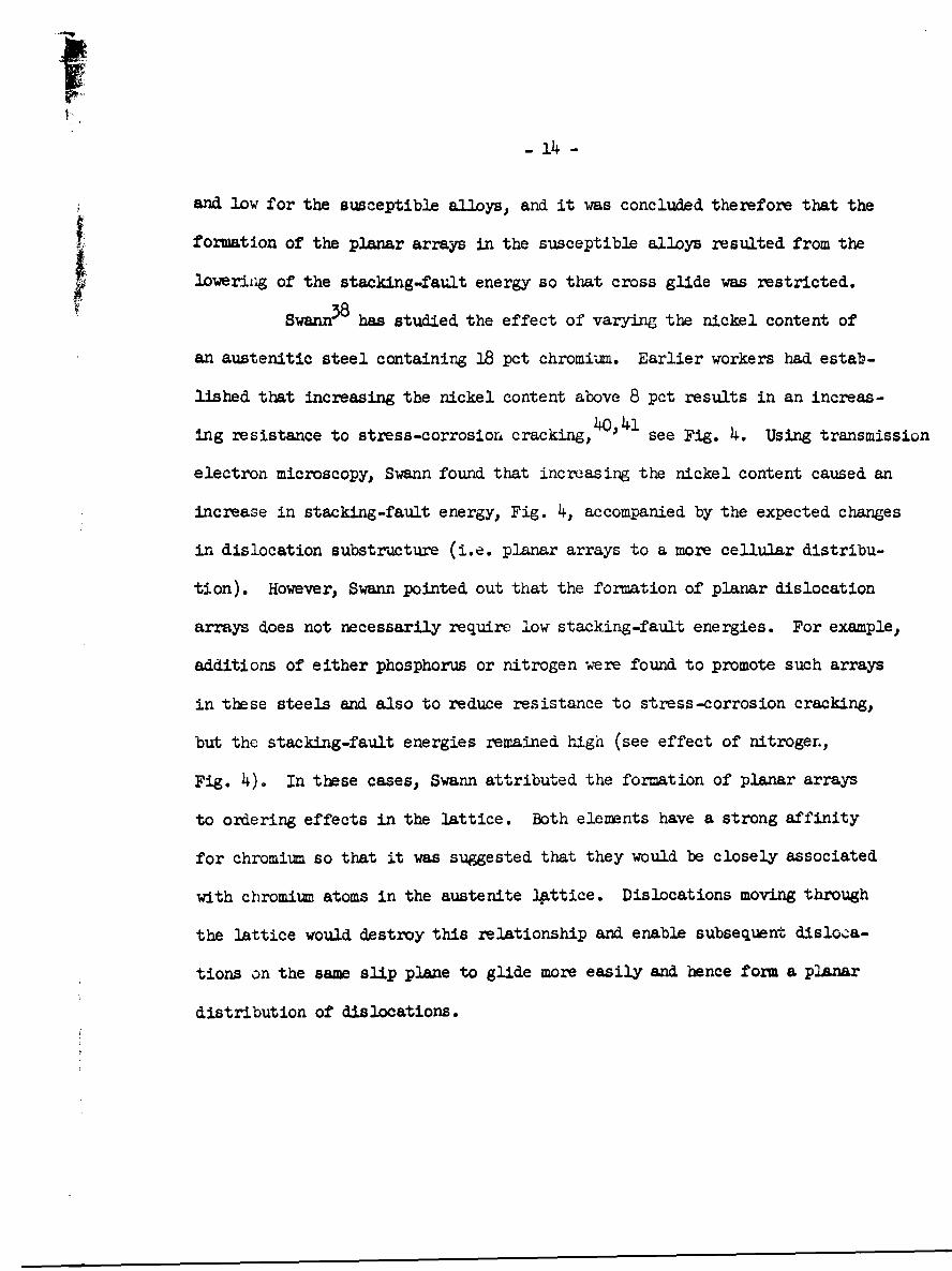
and low for the susceptible alloys, and it was concluded therefore that the
formation of the planar arrays in the susceptible alloys resulted from the
lowering of the stacking-fault energy so that cross glide was restricted.
Swann38 has studied the effect of varying the nickel content of
an austenitic steel containing 18 pct chromium. Earlier workers had estab-
lished that increasing the nickel content above 8 pct results in an increas-
ing resistance to stress-corrosion cracking,4o,41 see Fig. 4. Using transmission
electron microscopy, Swann found that increasing the nickel content caused an
increase in stacking-fault energy, Fig. 4, accompanied by the expected changes
in dislocation substructure (i.e. planar arrays to a more cellular distribu-
tion). However, Swann pointed out that the formation of planar dislocation
arrays does not necessarily require low stacking-fault energies. For example,
additions of either phosphorus or nitrogen were found to promote such arrays
in these steels and also to reduce resistance to stress-corrosion cracking,
but the stacking-fault energies remained high (see effect of nitroger.,
Fig. 4). In these cases, Swann attributed the formation of planar arrays
to ordering effects in the lattice. Both elements have a strong affinity
for chromium so that it was suggested that they would be closely associated
with chromium atoms in the austenite lattice. Dislocations moving through
the lattice would destroy this relationship and enable subsequent disloca-
tions on the same slip plane to glide more easily and hence form a planar
distribution of dislocations.

- 15 -
o SC DATA .NF 4NF100 SFE DATA 0 .0,
8 12 16 2 1.0
0.004N - g 13LLO 50t 0.5 G b
0iý -0.5 zI
0
0
0Ak&~-'~ A I a 08 12 16 20 24Ni CONTENT (wt. %)
Fig. 4- Effect of nickel content on stacking-fault energy and tie to
stress-corrosion failure of - 18 pct chromium stainless steels. (After
Swa.nnB. )

-16 -
These observations suggest that the formation of planar dislocation
arrayo, caused either by low stacking-fault energy or by the existence of
ordering, is a necessary condition for transcrystalline stress-corrosion
cracking in austenitic stainless steels. However, recent work by Thoms,
Stickler and Allio42 suggests that the formation of such arrays is not a
sufficient condition, for it was found that while both 304 stainless steel
(18 pct chromium and 8 pcc. nickel) and Incoloy 800, an austenitic alloy con-
taining - 20 pct chromitz and - 33 pct nickel, exhibit plenar dislocation
arrays, the former was highly susceptible to stress-corrosion cracking in
boiling magnesium chloride solution while the latter was immune. More
significantly, Saxena and Dodd45 have reported that transcrystalline stress-
corrosion cracking occurs in an austenitic stainless steel containing 20 pct
chromium, 20 pct nickel, 1.5 pot molybdenum, and 0.3 pot carbon, despite the
fact that cellular dislocation structures were observed; there was no evidence
for the existence of planar arrays in the deformed material.
In copper-base alloys, it is accepted that stress-corrosion cracking
can occur in materials in which dislocations form either planar arrays or
cellular structures. For example, Thompson and Tracy have reported stress-
corrosion failures in a series of different binary alloys, including those
with zinc, aluminum and phosphorus, respectively. Electron-Microscope studies
have shown that planar arrays exist in copper-zinc and copper-aluminum alloys,
except for very dilute alloys 45, while cellular dislocation structures are
fo.med in the case of copper-phosphorus alloys' 6 .
- 17 -
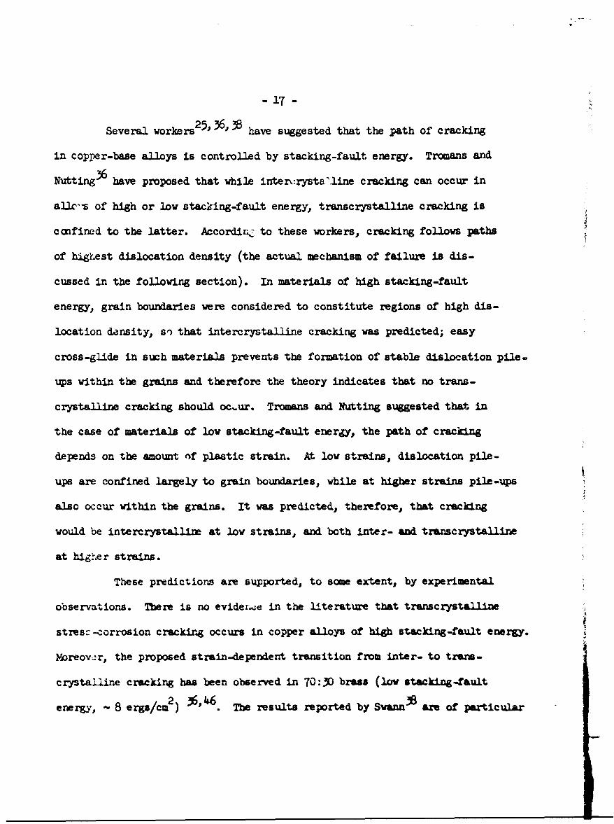
Several workers 2 5 ' 36 3 have suggested that the path of cracking
in copper-base alloys is controlled by stacking-fault energy. Tromans and
Nutting36 have proposed that while interxrysta'line cracking can occur in
allc-s of high or low stacking-fault energy, transcrystalline cracking is
confined to the latter. Accordirc to these workers, cracking follows paths
of highest dislocation density (the actual mechanism of failure is dis-
cussed in the following section). In materials of high stacking-fault
energy, grain boundaries were considered to constitute regions of high dis-
location density, so that intercrystalline cracking was predicted; easy
cross-glide in such materials prevents the formation of stable dislocation pile-
ups within the grains and therefore the theory indicates that no trans-
crystalline cracking should occ.ur. Tromans and Nutting suggested that in
the case of materials of low stacking-fault energy., the path of cracking
depends on the amount of plastic strain. At low strains, dislocation pile-
ups are confined largely to grain boundaries, while at higher strains pile-ups
also occur within the grains. It was predicted, therefore, that cracking
would be intercrystallire at low strains, and both inter- and transcrystalline
at higer strains.
These predictions are supported, to some extent, by experimental
observations. There is no evidezi.e in the literature that transcrystalline
stres- -corrosion cracking occurs in copper alloys of high stacking-fault energy.
iMoreov*r, the proposed strain-dependent transition from inter- to tzans-
crystalline cracking has been observed in 70:30 brass (low stacking-fault
energy, - 8 ergs/cm2 ) 3,46. The results reported by Svarmn are of particular
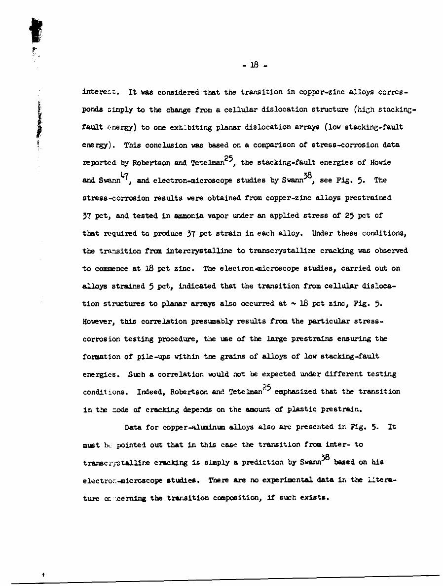
interet;. It was considered that the transition in copper-zinc alloys corres-
ponds simply to the change from a cellular dislocation structure (high stackine-
fault energy) to one exhlbiting planar dislocation arrays (low stacking-fault
energy). This conclusion was based on a comparison of stress-corrosion data
reported by Robertson and Tetelman2 5 , the stacking-fault energies of Howie
and Swann47, and electron-microscope studies by Swarm38 , see Fig. 5. The
stress-corrosion results were obtained from copper-zinc alloys prestrained
37 pct, and tested in ammonia vapor under an applied stress of 25 pct of
that required to produce 37 pet strain in each alloy. Under these conditions,
the transition from intercrystalline to transcrystalline cracking was observed
to commence at 18 pct zinc. The electron-microscope studies. carried out on
alloys strained 5 pct, indicated that the transition from cellular disloca-
tion structures to planar arrays also occurred at - 18 pct zinc, Fig. 5.
However, this correlation presumably results from the particular stress-
corrosion testing procedure, the use of the large prestrains ensuring the
formation of pile-ups within tne grains of alloys of low stacking-fault
energies. Such a correlation would not be expected under different testing
conditions. Indeed, Robertson and Tetelman25 emphasized that the transition
in the =ode of cracking depends on the amount of plastic prestrain.
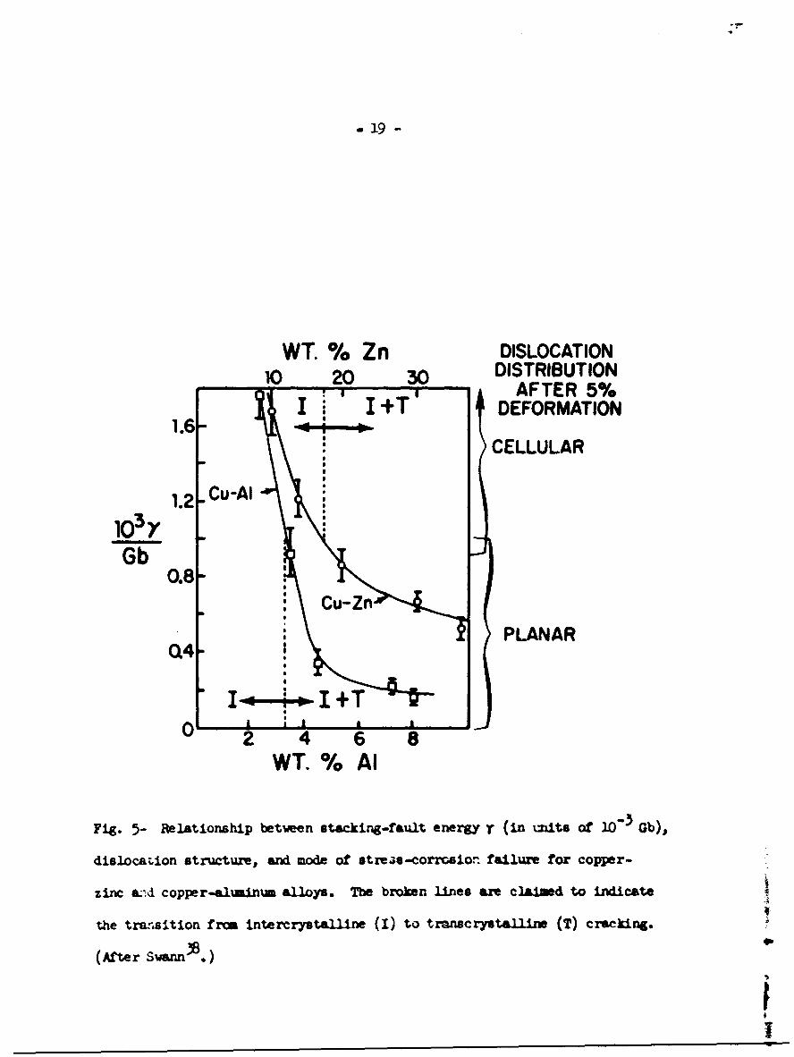
Data for copper-aluminum alloys also are presented in Fig. 5. It
must b& pointed out that in this case the transition from inter- to
transc:-1tallirm cracking is simply a prediction by Swnn3 8 based on his
electro: -microscope studies. There are no experimental data in the Uitera-
ture a: ccerning the transition composition, if such exists.
S19
WT. % Zn DISLOCATION10 20 30 DISTRIBUTION10• AFTER 5%
I I +T' DEFORMATION
CELLULAR
1.2 Cu-AI
Gb 0.8,:
Cu-Zn
PLANARQ4-
I pI +
I0
2 4 6 8WT. % AI
Fig. 5- Relationship between stacking-fault energy - (in i•itA Of 1C3 Gb),
dislocaLion structure. and mode of strems-corrrsion failure for copper-
zinc a-d copper-aluminia alloys. The broken lines axe c laiid to indLicate
the transition from intercrystalline (I) to transcrystaUlin (T) cracking.
(After Swa .)
I

- 20 -
To summarize, the earlier suggestionJ' that transcrystalline
stress-corrosion cracking in austenitic stainless steel occurs only in alloys
in which planar dislocation arrays are formed has not been confirmed by
later _rtudies. Thomas et al. 42 have shown that the formation of planar
arrays is not a sufficient condition for cracking to occur, and more recent
43work by Sauena and Dodd4' has indicated that such arrays are not a necessary
condition. In the case of copper-base alloys, the existing evidence sug-
gests -hat transcrystalline cracking is confined to materials of low
stacking-fault energy (i.e. those in which planar arrays are for.ed). How-
* ever, the relevance of dislocation structure in copper alloys car. be
questioned, since it has been shown that either trans- or intercrystalline cracking
* can be produced in an alloy containing - 37 pct z•ic by varying the pH of the
16environmeht
PROPOVSD MCHANISMS
The electrochemical theory proposed by Dix ar4 his coworkrs
serves as a useful introduction. According to this generalized model, a
prerequisite for stress-corrosion cracking is the existence of a localized
anodic path in the material. Thus in the presence of a corrosive aqueous
envirc=ent and a tensile stress, a galvanic cell is set up Ain which ;.he
anodic path is preferentially attacked. -2he base of the resulting corrosion
crevicc then '-:comes the site of stress concentrations, and these -vre thought
to cause the metal to "tear apart by mecharical action". It was considered

- 21 -
that the "tearing action" exposes fresh metal, unprotected by films, so
that accelerated corrosion occurs in this region. This in turn leads to
further stress concentration and further "tearing" of the metal. Ttus
cracking propagates by cycles of accelerated corrosion and "tearing" of the
metal.
While this model accounted for the apparent electrochemical nature
of stress-corrosion cracking, it left many questions unanswered, princi-
pally concerning the phrase "tearing apart by cechanical action". Later
workers interpreted this phrase differently. For example, Ublig con-
sidered that it referred to plastic deformation of the substrate, which
destr.7s protective films and thereby continually exposes fresh anodic
mater~a' to the envirorne.-.t. On the other hand, Harwood24 argued that
the ,.'.ase implied a stage of *-" rittle mechanical fracture of the metal
itsel'. These viewpoints clearly are diamttrically opposed. According
to th. former, crack propag&tion proceeds by prefrential dissolution at
the c:•&k tip, while according to te latter cracking is mechanical. It
would upear that this question could be readily resolvea by studies of
crack - ropagation, but unfortunateiy ilt is difficult to interpret the re-
sults or such studies unambig'•usly. ,n fact, this dichotomy still exists
-- b: narny theories waich haw. been proposed sLnze the early theory of
Dix e-. al. 2ali into two maiLn groups: (i) those which consider cracking
proce-. 'z by preferential dissolution, ( ti) those which consider .hat cracking
m c..&ric al. &

- 22 -
Conrsider the main problems faced by the two groups. Proponents
of the dissolution theory have to e:pjlain how dissolution is concentrated
at the crack tip and have to accouwt for the high rates of crackirg commonly
observed. For example, it has been claimed that a characteristic cracking
rate * of 1 cm/hr exists for many stress-corrosion systemsSO; tnis rate is
thought to be considerably higher than normal corrosion rates38. On the other
hand, any mechanical mode-3 must account for the occurrence of brittle failures
in normally ductile materials. Contrary to thn statement of Robertson and
Tetelman2 , concerning the intercrystalline stress-corrosion cracking of
homogeneous fcc alloys, that "it is not hara to imagine that the (corroding)
boundary can be weakened so that small stress concentrations at the boundary
can provide the eneigy to cause fr.cture", it is in fact difficult to ex-
plain in detail how failure occurs. Harwood 2, for example, has suggested
that plastic deformation at the tip of the corrosion crevice produces
"conditions of constraint and multiaxial stresses" which in turn lead to
brittle cracking. However, it is difficult to reconcile this model with the
behavior of materials such as austenitic stainless steel and a-brass which
show no notch sensitivity in the absence of the embrittling species. This
criticism can also be 3evelled against the more recent suggestion by
Nielsen91 that the deposition of solid corrosion products within a corrosive
crevice in austenitic stainless steel can assist in producing stress-corrosion
The reliability of measured rates of cracking is questionable because in many
system= it is not known whether cracking is continuouz or discontinuous.
- 23 -
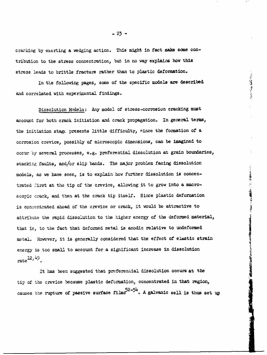
cracking by exerting a wedging action. This might in fact make some con-
tribution to the stress concentration, but, in no way explains how this
stress leads to brittle fracture rather than to plastic deformation.
In the following pages, some of the specific models are described
and correlated with experimental findings.
Dissolution Models: Any model of stress-corrosion cracking must
account for both crack initiation and crack propagation. In general terms,
the initiation stagt presents little difficulty, since the formation of a
corrosion crevice, possibly of microscopic dimensions, can be imagined to
occur by several processes, e.g. preferential dissolution at grain boundaries,
stacking faults, and/or slip bands. The major problem facing dissolution
models, as we have seen, is to explain how further dissolution is concen-
trated first at the tip of the crevice, allowing it to grow into a macro-
scopic crack, and then at the crack tip itself. Since plastic deformation
is concentrated ahead of the crevice or crack, it would be attractive to
attribute the rapid dissolution to the higher energy of the deformed material,
that is, to the fact that deformed metal is anodic relative to undeformed
metal. However, it is generally considered that the effect of elastic strain
energy is too small to account for a significant increase in dissolution
l2; 49rate
It has been suggested that preferential dissolution occurs at the
tip of the crevice because plastic deformation, concentrated in that region,
causes the rupture of passive surface films52"54. A galvanic cell is thus set up

- 24 -
between the film-free region at the tip of the crevice (anodic) and the filmed
sides of the crevice (cathodic). Dissolution at the tip leads to further stress
concentration and hence to further localized plastic deformation, which in
turn prevents the reformation of the passive film in that region and thus
ensures further localized dissolution. Cracking then proceeds by repeated
cycles of deformation and dissolution. Film-rupiure mechanisms of thistype have teen advocated by Champion 5 2 and Logan . The mechanism is
similar to that of Dix et al. but it differs from the latter in that
it does not imply any stage of mechanical cracking of the metal itself.
Moreover, it does not require a pre-existing anodic path.
A criticism of the film-rupture model was that it does not account
for the absence of marked susceptibility to stress-corrosion cracking in pure
metals, which also become coated with passivating films. This objection has
been met by recent developnents of the film-rupture mechanism, notably by
Swann and Embury55 . These workers, considering transcrystalline stress-corrosion
cracking, argue that surface films are more likely to be ruptured by coarse
than by fine slip. The height of slip steps in pure metals and dilute alloys
is small and therefore it was considered that film rupture is unlikely. On
the other hand, alloys of low stacking-fault energy or alloys in which
ordering exists, exhibit coarse slip and in these materials film rupture can
be expected. This argument thus predicts a correlation between susceptibi-
lity to transcrystalline stress-corrosion cracking and coarse slip (i.e.

- 25 -
planar dislocation arrays). It was seen above that there is meager evidence
for such a correlation.
The film-rupture model for transcrystalline stress-corrosion crack-
ing, as modified by Swann and Embu•ry", can be summarized as follows:
(i) Formation of a passive film over most of the surface.
(ii) Rupture of the film by slip.
(iii) Tunnel corrosion at the exposed metal, leading to the formation of
tubular corrosion pits. Pits of this type have been observed by
Pickering and Swann56 in several alloys, viz. copper-zinc, copper-
aluminumn, and magnesium-aluminum alloys, after exposure to solutions
which cause stress-corrosion cracking. Nielsen57 has reported a
similar type of tunnel corrosion in austenitic stainless steels
exposed to boiling aqueous magnesium chloride solutions.
(iv) Ductile rupture of a slot weakened by many tubular pits.
This model is illustrated schematically in Fig. 6. It differs from
the earlier film-rupture theories ' in that it involves tunnel corrosion
and stages of ductile fracture of the metal itself.
The cause of tunnel corrosion is not fully understood. Nielsen57
suggested that the tumnels in stainless steels may form by corrosion along
Lomer-Cottrell dislocations. narrow stacking-fault ribbons, or alpha ferrite
needles. The first two of these possibilities seems unlikely in view of the "A
observations by Swann and his colleagues that dislocations within the slip
This model was developed from earlier mechanisms proposed by Bvannm , and
56by Pickering and Swann

- 26 -
STRESS STRESS+ +
SLIP PLANE/ TRACE
/
// CORROSION PIT/
i , 6 -1 :, ,/
CORROSION PITDUCTILEFRACTURE
(a) (b)
Fig. 6- Schematic representation of film-rupture mechanism for stress-
corrosion cracking. (a) Pits are initiated at areas where surface Ulrs
have been ruptured by slip. Under suitable conditions the pits grow into
tubular tunnels. (b) Rupture occurs along a plane containing the corrosion
tunnels. (After Swann and Embury 5 .)

-27 -
band are not favored sites for initiation of the tunneisb, and that the
tunnels do not necessarily follow slip planes 56. Westwood" has pointed
out that similar tunnels have been found in lithium fluoride following
immersion in water containing a strongly-adsorbing step-poison, e.g. fatty
'9 60acid molecules or ferric fluoride complexes ; tunneling was not observed
in the absence of such poisons. It was suggested., therefore, that the pre-
sence in solution of certain strongly adsoiLbing species. may be responsible
for the tunneling found in materials e;.-osed to environments which cause
stress-corrosion cracking. In this connection, it is interesting to note
that the chloride ion has been found to be strongly adsorbed on surfaces
of austenitic stainless steel61.
An alternative disiolution model has been proposed by Hoar and
Hines62, based on the corept of mechanochemical anodic dissolution.
According to this approach, anodic dissolution is directly assisted by con-
tinuous plastic deformation. Thus yielding at the tip of a corrosion cre-'
vice is thought to cause preferential dissolution in that region, and, as
in the film-rupture model, this causes further localized deformation. In
this case, cracking then proceeds by continuous yielding arid localized disso- Ilution at the crack tip. Later work by Hoar and his colleaguss3OS'l has been
claimed to provide evidence for the mechanochemical effect. For exaples, Hoar
and ScullY 1 have investigated the effect of continuous yielding on the disso-
lution behavior of wires of 38 pat chrmi••, 8 pet nickel stainless steel in
boiling 42 pot aqueous mnesium chloride solution, maintained at a constant
potential by means of a potentiostat. The anode current dernity was foun to

-28 -
increase significantly with increasing strain rate, Table I, indicating that
yielding causes increased rates of anodic dissolution
a The mechanism of the proposed mechancmechanical effect has not been
explained, although it has been suggested that the arrival of dislocations
increases the number of anodically active sites by disarraying the surface•0
It was further suggested that this effect would be greater in materials
which shov restricted slip (i.e. materials exhibiting planar dislocation
arrays) than in those which aa cross slip readily. This argument would
appear debatable, since many small slip steps might be imagined to provide a
greater number of active sites than several large steps.
The film-r~pture model and the mechanism based on mechanochemical
anodic dissolution can be seen to display several comon features. In
particular, both are considered by their advocates to be operative in sun-
tenitic stainless steels undergoing stress-corrosion cracking in boiling
42 pet aqueous magnesium chloride solutions. It is interesting that the results
of Hoar and Scully•, Table I, presented as evidence for the mechanochemical
model, would also appear to be consistent with the film-rupture mechanism
-- increasing strain rates would be expected to lead to increasing d~ma
to surface films and hence to increasing anodic dissolution. However, it
is c only claimed, on the basis of electrode-potential stuties, that
passivating films are not formed on stainless steel in aqueous maesimu
chloride, particulirly in solutions acidified by the addition of smrwll
amounts of hydrochlortaca. on the other hand, recent metllographic
evidence by Swann ar led.b T, using a platinum decorating technique5,
-29-
suggests that a film is formed and, moreover, that it is r~ptured by plastic
deformation of the substrate. It is clear that further work Is necessary
to clarify the rple of surface film in this system.
The final dissolution model to be considered involves the suggestion
that solute atoms segregate to dislocations created during stressing, thus
cauasing preferential attack at these defects6 . This approach has been
developed by Trvmans and Nutting-, vho pointed out that the path of cracking
vou.A therefore be expected to depend on the dislocation structure of the
stressed material, This model ws discussed above, where it was seen that
it accounts to scme extent for observations on the path of cracking In copper
alloys. Tromans and Nutting proposed that cracking occurs priarily by a
single -stage mechaneam Involving a rapid rate of chemical attack at disloca-
tions, and the linking of these corrosion sites to fore wacrocracks. Hov-
ever., it could be argud that the theory In essentially one for crack initia.-
tion, since it leaves many questions unanswered concerming crack propagation.
In summary, then., the main dissolution models are:
(1). The film-rupture theory.
(2). The theory involving the concept of menhanochesial anodic dissolution.
(3). The theory based on preferential dissolution at "decorated" dislca-
tions.
Mechanical Models: It vas seen above that the major problm faced by
mcharncal models Is to explain how the presence of a corrsive enviro nt
cames cracking in normal1y ductile materials. Ag-ahertning aluminum allays

- 30 -
represent a special case because they possess sn inherent structural weak-
ness. Preferential grain-boundary precipitation during aging leads to the
formation of precipitate -free zones at the boundaries in these alloys,
Fig. 764. The zones are mechanically weak compared to the solid solution
Within the grains so that upon stressing they become the sites for preferen-
tial deformationo Thomas and Nutting have suggested that grain-boundary
deformation plays an Important role in stress-corrosion cracking. alt.ough
the process vms not discussed in detail.
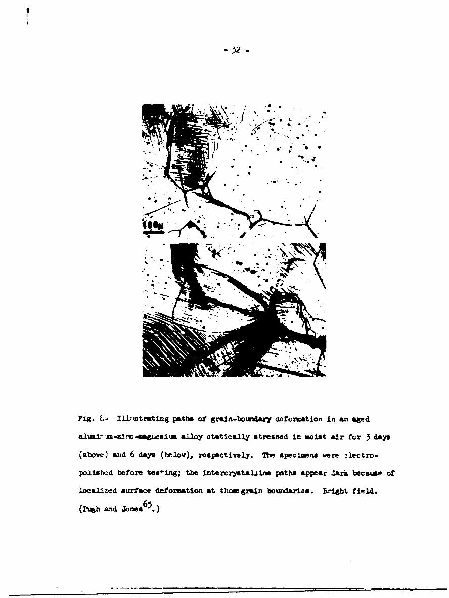
Pugh and Jones 6 5 have considered the stress-corrosion cracking of
a high-purity aluminum alloy containing 5.5 1 0 zinc and 2.5 pct magnesium.
Stu•les of the surfaces of aged specimens undergoing stress-corrosion crack-
ing In moist air indicated that the first stage in the process was the
formation of continuous paths of grain-boundary deformation. Fig. 8, perpen-
dicular to the tensile axis. The grain-boundary paths illustrated In
Fig. 8 appear dark and well-defined because of severe surface rmpling at
the boundaries caused by deformation within the precipitate-free zones; no
cracks were present. The length of the paths., and the amount of deformation
in the neighboring grains, was observed to increase with time. Fracture
finally occurred over an intercrystalline path which included a deformed
path. The significant feature of these observations was that no cracks were
detected along the deformed paths before final fracture. It was considered,
therefore, that cracking occurred tV rapid, mechancal, fracture.

- 31-
vi
FUg. 7-. Trnuls electron sicragmphi illustruting the pzmcpitate-
free zones at pstrn bomWIaies in an age almminw-lm-s-mauesila allay,
(After Thcuas MAz Itttl*. 6)
- 32 -
I 0• • * -, . S
Fig. £- I11strating paths of grain-boundary aefozmation in an ad
aliuaI,, J-zITc- gWiCsi~u alloy statically stressed in moist air for 3 ~y
(above) ad 6 days (below.), respectively. The specimens •re ectro-
polishead before tes"'Ing; the intercrysta.1ire paths appear dark because of
localized surface deformation at thaw grain boundaries. Bright field.
(Pugh and Jns6.

- 35 -
The fo.luving mechanism was proposed to explain these observations:
Grain boundaries in alloys of this type are known to be anodic relative to
the grains, and it is thought that exposure to coirosive envirorments leads
4,48to localized attack at grain boundaries, formin corrosion crevices -*
In the presence of tensile stresses, stress concentrations set up at the
extremities of these crevices are relieved by plastic deformation within the
precipitate-free zones. The preferential deformation in turn ruptures pro-
tective (oxide) film in the grain boundary regior,, leading to further
localized corrosive attack. In this way, cycles of localized corr .ock and
deformation occur at certain grain boundaries. Moreover, corrosion crevices
near the extremities of the initial paths of deformation create stress-
concentrations which are relieved by plastic deformation in the adjoining,
previously undeformed precipitate-free zo.e, thus cawsing the growth of the
deformed path. At tUL samw time., repeated !ycles of corrosion and preferen-
tial deformation along the path resut in hardening and eventual crack
initiation. In the coarse-graine specimens (4 grains/u 2 ) ue i
these experiments, the initial crack propagated catastrophically tthrough the grain-boundary zones. This would not be the case in ma er-i. of
fVner grain size, in which several cycles of g win-ýourniary creep &.-A mechanical
fracture would be expected.
The stuiies of Pugh and Jones were confined to high-purity alloys
conta.i..ing zinc and nagnesiiza. Howve r, precipitate-e! zone s axe known to
exist in other age-hardening alxain~u alloys 0, and there is evidence that Jcrack propagation is nechanical in these alloys 6 6 . Tberefore, it is con-.
sider-, likely that the some mechanism is operative.
4

- 34 -
While the mechanism outlined above accounts for many characteristics
of stress-corrosion failure in aluminum alloys, several aspects of the pro-
cess require further study. For example, the stress-corrosion life of age-
hardening aluminum alloys is known to decrease with increasing aging time
to a minimum value., after which it progressively increases68,69 (see Fig. 9 69).
It has been claimed that minimum life occurs at maximum hardness, because
the difference in hardness between the grains and the precipitate-free zones
is thought to be greatest at this stage14 ' 6. However, studies of high-
p.trity alloys containing 5.5 pct zinc, 2.5 pct magnesium, and separate additions
of small amounts of either copper, manganese, chromium, silicon, or iron,
have indicated that minimum life occurs considerably earlier in the aging
69process than peak hardnesp6. A typical relationship between stress-corrosion
life and hardness is illustrated in Fig. 9. No explanation has been put
forward relating the minimum life with structural changes during aging.
A second area requiring further attention concerns the nature of
the fracture surfaces. According to the proposed mechanism, crack propaga-
tion is purely mechanical. Brittle intercrystalline fracture also can be
produced in alloys of this type in conventional tensile tests, and in these
instances the fracture surfaces are characterized by a dimpled pattern,
thought to result frcui plastic deformation in the precipitate-free zones
ahead of the advancing crack 7 0 . It would be expected, on the basis of the
preceding model, that fracture surfaces produced during stress-corrosion
cracking would show a similar structure. However.. fractographic studies by
Forsyth and Ryder70, carried out on a stress-corroded commercial aluminum-
zinc-magnesium alloy, have indicated that two distinct types of intercrystalline

- 35 -
D.0 0 HARDNESS
S7-
ALLOY SOLUTION TREATED 1FOR 3 HRS. AT 4650C D.P.CNWATER QUENCED, AND
D /o AGED AT 1200 C.ý! 50 -0
STRESS- CORROSIONwJ DATA
10010 20 30 40 50 DPN.
AGING TIME (hours)
Fig. 9- Effect of aging time or. hardess, and on stress-corrosion life
for a high-purity aluminum alloy contaening 5.7pct zinc, 2.5 pct magnesiumI
and 0.2 pct iron. (Pugh'.)

-36-
fracture surface exist. One type was found to exhibit the dimpled pattern,
but in the other case the surfaces were smooth, indicating that cracking
was accompanied by little plastic deformation. It is possible that the
smooth surfaces correspond to the initial stages of fracture through the
severely work hardened grain-boundary zones. and that the dimples occur when
the crack enters previously undeformed regions. However, further metallo-
graphic studies are necessary to confirm this.
It is clear that the mechanism outlined for aluminum alloys cannot
be applied To the more general case of inherently ductile single-phase
materials such as a-brass and austenitic stainless steels. Several
workers29.49,71 have suggested that stress-corrosion cracking in such cases
Wa result from the adsorption of specific ion species. Following the
appzoach used by Petch in his theory for the hydrogen embrittlement of
steels7 2 73., Coleman et al.29 proposed that the role of adsorption is to
lower surface energy. According to the Petch-Stroh relationship (see
above),
OF = + K d-/21
where aF is the stress required to cause brittle fracture, d is the average
grain diameter, and a and K are constants. In particular,
26 " " [2]

37
where G is modulus of rigidity, v Poisson's ratio, and r the surface energy
associated with the formation of new surfaces by fracture. Thus, fcr con-
stant grain size, it follows that if r is reduced by any process, then OF
also will be reduced.
Coleman et al. determined the stress necessary to initiate stress-
corrosion cracks as a function of grain diameter, d, for both a magnesium
-6 pct aluminum alloy in a sodium cloride-potassium chromate solution, and for
an 18-8 austenitic stainless steel in aqueous magnesium chloride solution.
The relationships between the stress and d"12• were claimed to be linear in
both cases, e.g. Fig. 3. From the slope of these relationships and from
Eq. [2], T was found to be 93 ergs/cm2 for the magnesium-base alloy,2
and 157 ergs/cm for the steel. These values are considerably lower than
estimates of the true surface energies for these materials, - 500 and
21000 ergs/cm, respectively. It was considered that the reduction in y
was due to adsorption, and that this reduction allowed brittle failure to
occur in these materials.
This conclusion can be questioned from two standpoints. First,
it can be argued that the data do not provide convincing evidence that the
Fetch-Stroh relationship is obeyed,, since the grain-size dependence, if it
exists, is extremely small (see Fig. 3). Second, if it -,.s accepted that
this relationship is in fact obeyed, then the meaning of the surface energy
term. -, can be questioned.- It would appear that this term should more
properly represent the total energy involved in the creation of new surfaces.
I145

-38 -
thus including such terms as the surface free energy, the energy expended
by plastic deformation, and the chemical energy supplied by the environment.
The relative contribution of these terms to the total energy is a matter
for speculation. Thus, viewed in this light, the claim that embrittle-
ment results from an adsorption-induded reduction in surface free energy
clearly remains to be demonttrated.
The surface-energy mechanism also can be criticized on the grounds
that it does not explain the specific nature of the environments which
callse stress-corrosion cracking, nor does it account for the relative
immunity of pure metals to this failure. Furthermore, the surface-energy
approach, which has alsc been put forward to explain liquid-metal embrittle-
ment 7 5 , has been criticized because it does not give any insight into the
mechanism of failure on an atomic scale1 3'76. More recently, an alterna-
tive adsorption-dependent mechanism has been proposed for liquid metal
embrittlement, according to which embrittlement results from the adsorption
and interaction of specific species with strained bonds, causing a localized
reduction in cohesive strengthl357 6 .77. In addition, recent work has
suggested that the embrittlement of the non-wetal silver chloride in certain
5-8aqueous solutions occurs by a similar adsorption-dependent mechanism
The embrittlement of silver chloride is of particular interest be-
cause it displays many of the phenomenological characteristics of stress-
corrosion cracking in metals:
(i) Fracture of polycryszals stressed in air is ductile and transcrystalline,
but becomes brittle and intercrystalline when the tests are conducted in
5-8certain aqueous environments
-3.9 -
(ii) In tests under constant load, the relationship betwen time to failure,
t .. and the stress level is similar to that for metals undergoing stress-
corrosion cracking, cf. curve A, Fig. 105 and Fig. 1.
(iii) Environments which cause embrittlement are specific. In each case,
dissolution of the specimens in embrittling solutions leads to the formm-
tion of silver complex ions, Table II. Complex ions in solutions which camse
cracking can have different stru-tures and can be either positively or
negatively charged, but the magnitude of the charge must be high, > 1+
and > 2-, Table II •
It has been proposed that cracking in silver chloride results from
the adsorption of highly charged complex ions at regions of stress concen-
tration6 . For example, intercrystalline cracks are commonly initiated
when slip bands are arrested at grain boundaries of large misorientation,
Fig. 11(a); on the other hand, cracking is not observed at boundaries where
the stress fields associated with the blocked slip bands are relieved by
slip in •he neighboring grain, Fig. 11(b) 7 . Once a crack is formed, the
tip itself becomes a region of stress co.aentration. It was s~ested that
adsorption of the complex ions at strained bonds perturbs the distribution
of bonding electrons , reducing bond strength and hence Ulowing rupture at
reduced stress levels.
Embrittlement in silver chloride was considered to result from
adsorption rather than from, say, stress-dependent dissolution for several
reasons:
Bondi:.g in silver chloride is thought to be 70 pct covalent and 30 pct
78ionic

I
-40 -
S CURVE o6N NoCI, UNSTIRRED800RVA *6N NoCI , PRESAT. WITH
SILVER CHLORIDE COMPLEXESE '• 6N NoCI, LARGE VOLUME,E STIRRED
Ul)U)wI-Uf)
400L 10 102 103 104TIME TO FAILURE (sec)
Fig. 1>- Effect of applied stress on the time to failure of polycryst&liine
silve.: chloride stressed in 6N aqueous sodium chloride solutions at room
teempe-rature. (Westwood et al.5)

Table II. The Relationship between the Charge on Silver Complex Ionsand their Abiligyto Dnbrlttle Polycrystalline Silver Chloride (afterWestwood et alI.
SOLUTION PREDOMINANT CHARGE ENMPITLEMYTCOMPLEX ION
lON NH40 A (1H 1+ N•o. m~o• .•(•3)2 .
< o.1N AgNO,3 A.2C* +
0.lN hCl Ag6l• 1-
1iac g 2-. 2-
uN CsCl (AgCl•3). n+
5.3N KiU (AgCl),,f• U "
17'N Ag. 3 Ag Cl 2+ 2+ X&S
6N NeCi Agl 3-
11.8N Hc
13.8N LiCi
8N N.Br AgBr
20,14Likr
171N N&SCN A(C)P
6.% k2S203 A g(SPO3) 3 5-
•7• • •s•)•-1

-42-
Fig. 3A1 Specimen of Po3.yerystalline silver chloride deform~ed in 6N sodium
chloride solutions presaturated with AgCl3- ions. (a) Cracks are initiated
where slip is arrested by' a grain boundary of suitably large misoricntation.
(b) Cracks are not formed when the boundary is such that stress-concentrations
associated with arrested slip bands are relieved by slip in the neighbor-ing
grain. Tran~mitted light. (Westwood et al.7 )
(i) t. was observed to decrease marzkedly when the testing solutions were
presaturated with the silver complex ions before testing, •ig. icP.
Similarly, t. for specimens tested in "unpresaturated" solutions increased
when the volume of the test solution was increased Yig. 10; this was attri-
buted to the fact that longer times were then required to produce a suffi-
cient complex-ion concentration to cause cracking .
(ii) Embrittlement did not occur in potassium chloride solutions 6 , despite
the fact that the solubility of silver chloride in these solutions is
virtually the same as that in sodium chloride solutions of the saw Cl"
ion concentration79 (sodium chloride is highly embrittling, see Fig. 10).
The reason that potassium chloride does not cause embriftlement is thought
to be because mixed potassium and silver complex ions of charge < 3- are
fomed in this cast 80 see Table II.
(iii) Fractographic studies of both poly- and monocrywtal specimens indi-
cated that striae existed, Fig. 127. These markLngs., which were perpendi-
cular to the direction of crack propagation, were considered to result from
a discontinuous fracture process. caused by the inability of the slowly I
07diffusing complex ions to keep up with the advancing crsck'.
While the preceding observations are consistent with an adsorption-
dependent mechanism, they cannot be explained in terms of a dissolution-
dependent model.
The observations on sa _.r chloride would appear to support, by
analogy, the view that an adsorption-dependent process is operative in stress-
corrosion cracking of metals 29 ,vo7, and that the role of corrosion my be

-44-
Fig. L?- Fracture surlace of a sirgle cr'rtal of silver chloride stressed
ir. 6& sodium chloride solution presaturated with AC ion" . illtrating
strise. The direction of crack propagation is indicated by the arrow.
Bright field. (Westwood et ai. 7 )

to produce (via dissolution) the specifL ion species responsible for
29cracking . In this connection, the failure of a-brass in ammoniacal
environments is of particular interest, because dissolution of copper in
such envirorments leads to the formation, of cupric complex ions of the
geneal tpe QOM 2+ Moreover,, At has been demonstrated 885tiifý,S83 n
the life of braes ipeclzens in aqueous aamonia is markedly reduced when
lae concentrations of these ions are introduc2d into the solution 7 o'o-
the test cCwncies, e.g. Fig. i?5. By analogy with the obsermtions a
the embrIttlement of silver chloride, these results suggest that failure
in brass may also resilt frci adsorption of complex ions. Bowever, it will
be seen in the fol'owvir section that this is not the case.
Tbe possibility that the role of .-orrosion is simply to provide the
embrittling ion specie6 has bee. investigated2 3 by cowur*ing stress-corrosion
life in "fresh" and "preioncentrated" solutions for (i) a magsium-aluninum
alloy in aqueous sodium chloride - sadium chromate solution, (ii) an age-
hardened commrciaJ aluminum alloy (20-2-4) i aqueous odlui chloride, and
(iii) a 304 austenitic stainless steel. in boiling 421 magnesium chlc.id
solution . In each case, the testing solutions were pv-&atrmted by the
alidition of filings obtained from the material to 'e tested. No signifi-
cont variation in times to failure at a given stress were noted for aay of
the systems, e.g. see Fig. 1.
The experiments on the stainless steel were carried out by E. E. Denbard,
Arwo Steel Corporation, Palt1dore.
V
- 46 -
o INTER. CRACKING (No Visible Film)* INTER. CRACKING (Tarnished Layer)
CY 20 , MIXED CRACKING (Brown Film)EE
LUOXYGENATED A
AQ.ANH 3010I
zWU 0
LUz
(D5 AQ. NH3zLU CONTAINING
6Gg/1 COPPER
10 102 103 104 105TIME TO FAILURE (sec)
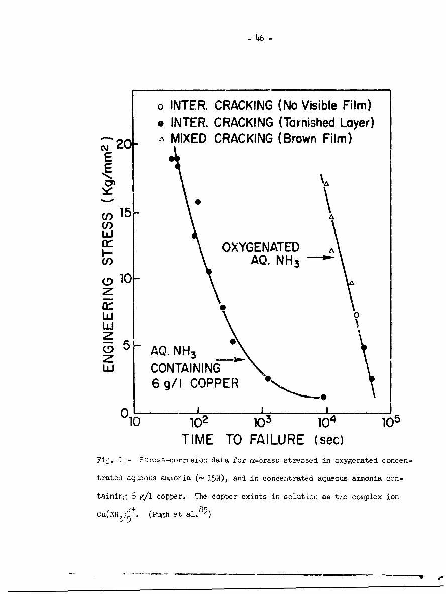
Fig. !-- Stress-corrcsion data for ar-brass stressed in oxygenated concen-
trated aqueous ammonia (,- 15N), and in concentrated aqueous ammonia con-
taininiL: 6 g/l copper. The copper exists in solution as the complex ion
Cu(NM,)_+. (Pugh et al.85)
,,5
- 47 -
It is concluded, then, that while there is good evidence for an
adsorption-dependent mechanism for the embrittlement of the non-metal silver
chloride in aqueous environments, there it, not, as yet, any unambiguous
experimental support for such a process in metals.
A significant advance in our understanding of stress-corrosion crack-
ing in a-brass has followed the recent proposal by Forty and Humble 8 6 that
cracking in certain ammoniacal solutions proceeds by the Lepeated formation
and rupture of a characteristic black oxide layer, commonly termed the
tarnish. The process is illustrated schematically in Fig. 14. The first
stage involves the formation and rupture of the tarnish, Fig. 14(a) and
Fig. 14(b). An essential feature of the theory is that the crack does not
propagate into the brass substrate, but becomes blunted by plastic deforma-
tion in the brass, Fig. 14(c)*. Fresh brass is then exposed to the tarnish-
ing solution, allowing the process to be repeated, Fig. 14(d) - 14(f). Crack-
ing thus proceeds in a discontinuous fashion, producing a fracture surface
similar to that illustrated in Fig. 14 (g).
Evidence for the tarnish-rupture model is convincing:
28(i) Fractographic studies by McEvily and Bond- established that striae exist
on stress-corrosion fracture surfaces, and that they were perpendicular to
the direction of crack propagation, Fig. 15. This is strong evidence for dis-
continuous cracking, and is thus fully consistent with the tarnish-rupture
model, cf. Fig. 15 and 14(g).
in bri ttle surface layers could propagate for a finite distance into the sub-
strate.

-48-
SLIP
(a) (b) (c)
SLIP
DIRECTION OF CRACKPROPAGATION
(g)
Fig. 14- (a) through (f). Schematic representation of tarnish-rupture
mechanism for stress-corrosion cracking of brass. (g) Resulting fracture
surface.

49
i
.. .. ..• • .! ... .
?tt
__ hiFig.• 15 Elecro Micrograp of relc- fsrs crrso rcuesr
face:':," in • a- 'ass Note•!: striae." (Ate ':~il and;.: Bond:,'"':

- 50 -
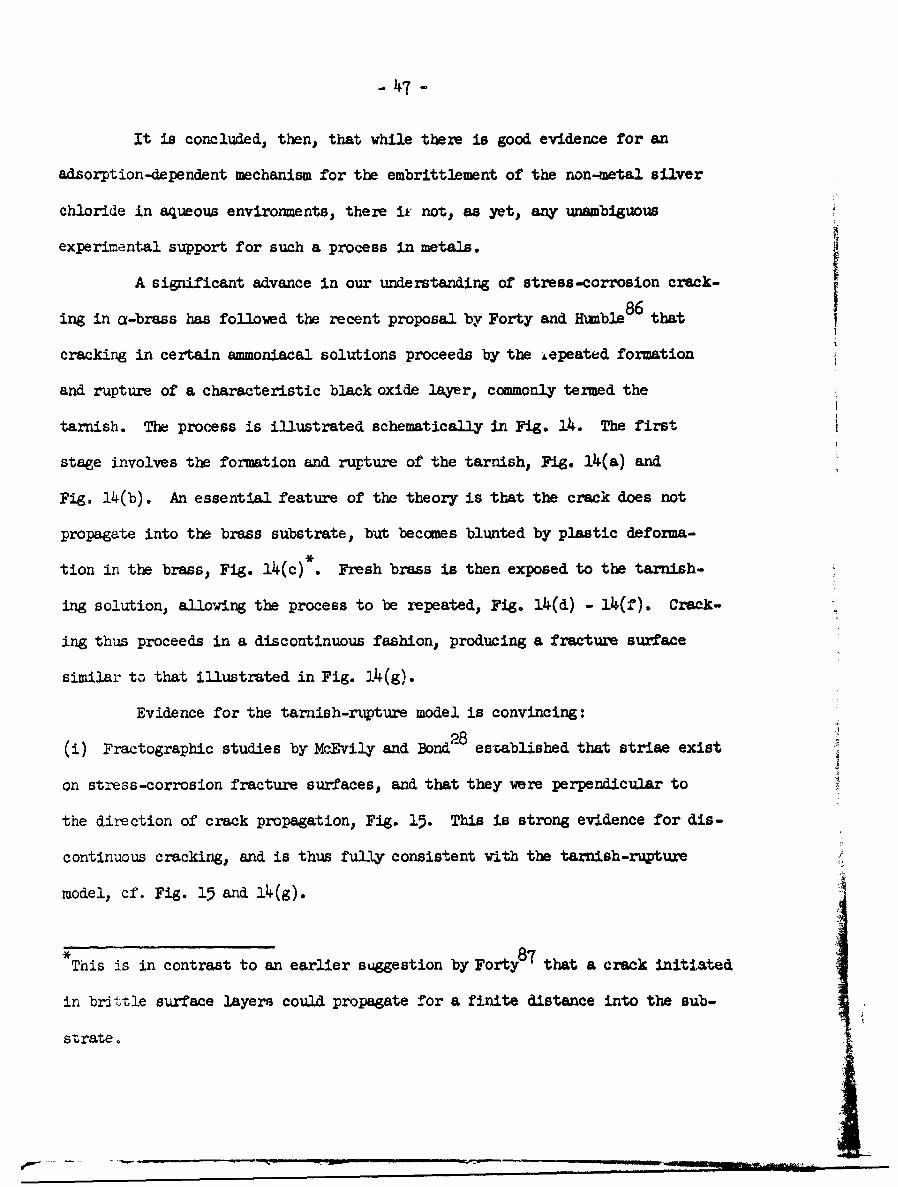
(ii) Forty and Humble86 have shown that "crack-like penetrations" can ba
produced in a-brass single crystals by repeated immersion of unstressed
specimens followed by stressing in the absence of the environment. Inter-
23crystalline cracks also can be propagated in this fashion . For example,
Fig. 16(a) illustrates part of an intercrystalline crack (the tip is marked
by the arrow) in a specimen that was immersed unstressed in a tarnishing solu-
tion for 10 mrin, and then washed, dried, and plastically deformed in air by
means of a manually operated jig. Note that the brass substrate is visible
at the base of the crack, Fig. 16(a); cf. Fig. 14(c). When the specimen was
re-immersed for a further 10 mrin, the base of the crack became tarnished,
Fig. 16(b); cf. Fig. 14(d). The specimen was then stressed and the crack
shown in Fig. 16 observed by reans of an optical microscope. By "pulsing"
the stress it was possible to propagate the crack discontinuously to the
grain-boundary triple point A, where it Joined a second crack which propagated
from B. In addition, the crack became deeper, the brass substrate being
barely discernible, Fig. 16(c); cf. Fig. 14(f). Repeated cycles led to com-
plete intercrystalline failure.
The extent of crack propagation during each stressing operation is
limited by the depth to which the tarnishing reaction has advanced beyond the
crack tip. Thus continued stressing during an intermediate stage resulted in
blunting of the cracks, and final fracture was ductile. The number of cycles
necessary to cause failure could be controlled by varying the time of immersion.
It was interesting to note that grtin boundaries of specimens immersed for many
hours became completely penetrated by the tarnish, and it was then possible to
fracture the specimens into many small pieces manually. Fracture was completely
intercrystalline in these cases.
Fig. 16- Illustrating the propagation of an intercrystaliine crack in
a-brass by immersing an =s~tressed specimen in a tarnishing solution
foll~ow~ed by stressing in air. See text for details. (Pugh and Wiestwood .)

- 52 -
Specimens ruptured in this fashion were closely similar in appear-
ance to those tested in conventional tests where the stress was applied
while the specimens were immersed in solution. Note that these observa-
tions would appear to invalidate the classical definition of Sutton et al.3
(see above), according to which stress-corrosion cracking requires the
simultaneous action of stress and corrosive attack.
The preceding observations provide strong support for the tarnish-
rupture theory. Moreover, they cannot be reconciled with dissolution models,such as that proposed by Graf and Richter83. However. the mechanism of
tarnish rupture is not fully understood. In single crystals, the morpho-
logy of cracks in the tarnish has been shown to be related to the slip
vector in the underlying brass 86. Homever cracking in polycrystalline
specimens is predominantly intercrystalline, and McEvily and Bond28 have
presented evidence that massive deformation of the substrate is not
necessary for tarnish rupture. These workers have suggested that cracking
may involve both dislocation motion in the tarnish, and epitaxial stresses.
Recent work23 has indicated that the original grain boundaries of the
brass are maSitained in the oxide, and it is possible therefore that these
act as barriers to dislocation motion (within the tarnish), resulting in
the initiation of intercrystalline cracks. Further work is necessary to
investigate the possibility of such a semi-brittle process.
While the tarnish-rupture model accounts for stress-corrosion
cracking in tarnished brass, there is evidence that failure also can occur
in ammoniacal solutions which do not caube tarnishingl16,4 6 A8 5. For example,

- 55 -
it hnz been reported that both stress-corrosion life, to and surface con-
dition of brass specimens tested in concentrated (-. 15N) aqueous ammonia
2+depend on the concentration of the complex ion Cu(NH3), present in the
environment46. Figure 17(a) illustrates the relationship between ti for
specimens tested under a constant load and the copper content of the solu-
tions, which in these experiments was directly proportional to the complex-
ion concentration. The concentration at which the well-defined inflection
occurred (- 2.7 g/1 copper) ws found to correspond to the onset of
tarnishing -- that is, specimens tested in solutions of lower concentration
were tarnish-free, while in solutions of higher concentration they were
tarnished. The onset of tarnishing also was reflected by a maximun in the
relationship between the rate of weight loss and the copper content of the
solution, Fig. 17(b). The initial increasing rates of weight loss with
increasing copper content has been shown 8 ' to result from the following auto-2÷
catalytic reaction between Cu(NB, ), ions and copper at the brass surface:
Cd(Mui)2, + Cu - > 2 Cu(NH3)+ + MLH3 > ~2 Cu(NH3).. 25]
Stage (a) of this reaction was considered to oczur only at tarnish-free
brass surfaces, so that the appearance of the tarnish causes a dec.+easing
rate of weight loss.
These and other observations indicated that two mechanisms of
stress-corrosion cracking are operative in a-brass8. The mechanism of
failure in the absence of the tarnish was not fully explained. The fact
that decreasing t with increasing copper content van accompanied with
i
_ _ _ _ _ _ I

104 54 -
I_ IT 11 V]I R
J 103 iENGINEERING STRESSI 17Kg/mrm 2
-J !(a)I -
w ,F--
I10 1 1_,__ , I I
~. 1.0_1N . I
E "k * SPECIMENS UNSTRESSED(I-) ,C AW -1
. 0.5 - ' 1 0'R S
0 0 0%V.
LL0z COPPER
I
SI ISp I , i ... I ,.I a , ..
0 5 10COPPER CONTENT (g/1)
Fig. 17- Effect of copper content of emmonia environment on (a) time to
failure of a-brass, and (b) rate of weight loss of unstressed brass and
copper specimens. The copper exists in solution as the cupric complex ion
Cu(NH3)2•+; the concentration of the latter is directly proportional to the
ccpper content of the solutions. (Pugh and Westwood46.)
• w• •- ... ..... .... .. i
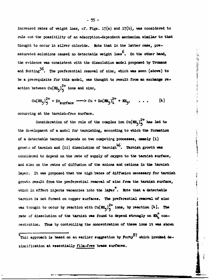
- 55 -
increased rates of weight loss, cf. Figs. 17(a) and 17(b), was considered to
rule out the possibility of an adsorption-dependent mechanism similar to that
thought to occur in silver chloride. Note that in the latter case, pre-
saturated solutions caused no detectable weight On the other bud,the evidence was consistent with the dissolution model propoted by Trmans,
and Nutting3 . The preferential removal of zinc, which was seen (above) to
be a prerequisite for this model, was thought to result from an exchange re-
2+action between Cu(N 3)5 ions and zinc,
2+ 2+Cu(NH3 )5 + Znsuace - CU + ZD(RE)+NHMy (1.]
occurring at the tarnish-free surface.
Consideration of the role of the complex ion Cu(IHR,), has led to
the development of a model for tarnishing, according to which the formation
of a detectable tarnish depends on two competing processes, Pnmely (M)
growth of tarnish and (ii) dissolution of tarni4h . Tarnish growth was
considered to depend on the rate of supply of oxygen to the tarnish surface,
and also on the rates of diffusion of the anions and cations in the tarnish
layer. It was proposed that the high 'rates of diffusion necessary for tarnishI
growth result from the preferential removal of zinc from the tarnish surface,
which in effect injects vacancies into the lafer . Note that a detectable
tarnish is not formed on copper surfaces. The preferential removal of zinc
was though to occur by reaction with Cu(fH,), ions, by reaction (4]. The
rate of dissolution of the tarnish was found to depend strongly on + con-
centration. Thus by controlling the concentration of these Ions it was shown
This approach is based on an earlier suestion by Forty8 7 which invoic do-
zincification at essentially film-free bras surfaces.

- 56 -
that the copper content of the solution at which tarnishing occurred could
be varied sIgnificantly.
According to the preceding discussion, the specif-c action of
oxygerated aqueous ammonia in causing stress-corrosion cracking in a-brass
stems frcm the presence of cupric complex ions such as Cu(NH2)5
(Cu(MH)A ions; have been found to behave s Thelarl of thee
ions appears to be to preferentially remove zinc, via reaction [4I, from
both tarnished and tarnish-free brass surfaces.
These considerations also are relevant to practical aspects of
stress-corrosion cracking in brass. For example, season cracking is
commonly observed in moist industrial atmospheres. Under these conditions,
it has been suggested that shallow layers of adsorbed water can pick up
oxygen and ammonia, thus setting up conditions favoring tae formation of
large concentrations of cupric complex ions and hence causing cracking85.
Similarly, it is wil known that failure in stressed specimens partially
immersed in aqueous ammonia generally occurs at, or just above, the level
of the solution. This effect can be attributed to conditions within the
meniscus i.e. small volume and ready access of oxygen. which again leads
to the formation of large complex-ion concentrations
The success of the tarnish-rupture theory in accounting for stress-
cvrrosion cracking in tarnished brass necessitates a re-examination of
fai u ns in other systems to determine vhethler a similar mechanism may be
operative. There already is evidence that oxide rupture plays an important
role --;:. the Cracking of gamms uranium alloys in certain aqueous environments
- 57 -
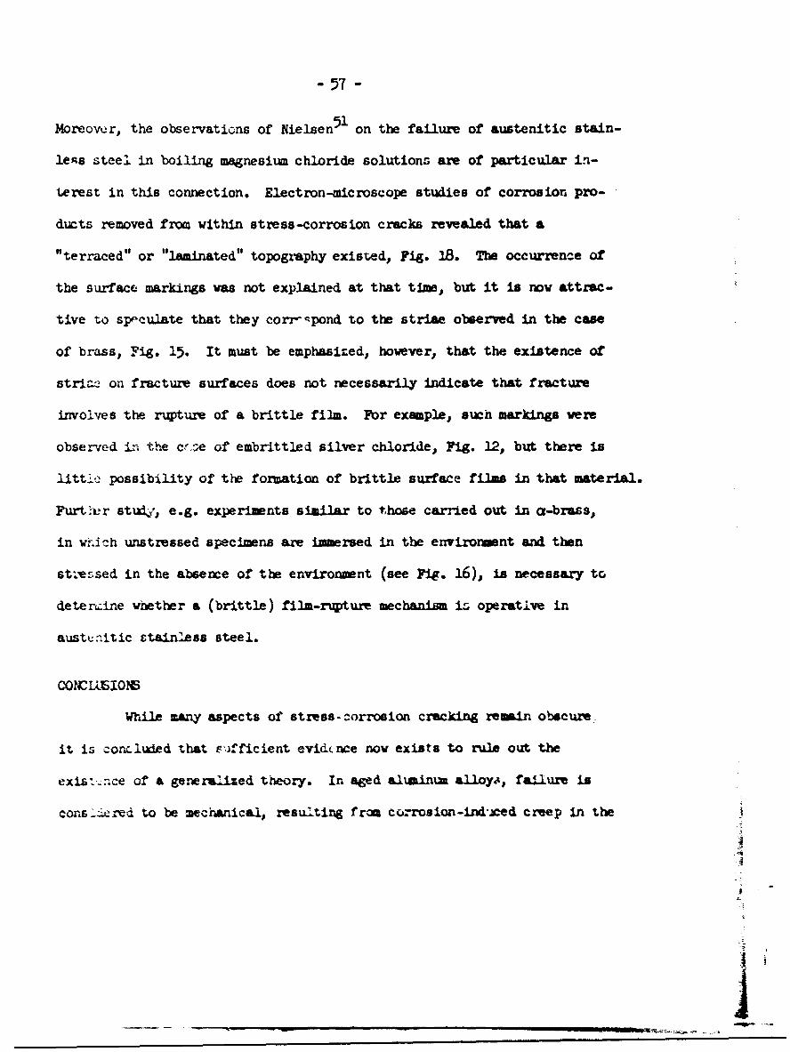
Moreovwr, the observations of Nielsen91 on the failure of austenitic stain-
lens steel in boiling magnesium chloride solutions are of particular in-
terest in this connection. Electron-microscope studies of corrosion pro-
ducts removed from within stress-corrosion cracks revealed that a
"terraced" or "laminated" topogiaphy existed, Fig. 18. The occurrence of
the surface markings was not explained at that time, but it is now attrac-
tive to speculate that they corrispond to the striae observed in the case
of brass, Fig. 15. It must be emphasized, however, that the existence of
striae! on fracture surfaces does not necessarily indicate that fracture
involves the rupture of a brittle film. Fbr example, such markings were
observed in th,.e e.e of embrittled silver chloride, Fig. 12, but there is
littlc possibility of the formation of brittle surface films in that material.
Furt.-r studj, e.g. experiments similar to those carried out in a-brass,
in wh.i-.h unstressed specimens are immersed in the environment and then
st;esed in the absence of the environment (see Fig. 16), is necessary to
detenrine whether a (brittle) film-rupture mechanism i, operative in
austcnitic ctainless steel.
CONCIL-EION6
WhIle many aspects of stress-.corrosion cracking remain obscure.
it is concluded that Fifficient evidtnce now exists to rule out the
existce of a genermrofed theory. In aged aluminim alloy,, failure is
cons -ered to be mecanical, resulting from courosion-indMced creep in the
A
F

Fig. 18- Transmission electron micrograph of corrosion product taken from
withini a stress-corrosion crack in austenitic stainlenis steel. Note
"striae". (After Nielsen 1 )

-59-
precipitate-free zones at grain boundaries. There is strong evidence
that the failure of a-brass in certain ammoniacal environments occurs
by the repeated formation and rupture of the brittle tarnish layer. How-
ever, failure also occurs in this system under conditions when no tarnish
is formed, indicating that a second mechanism is operative. The latter is
not fully understood, but it is suggested that it may involve a dissolution-
dependent mechanism of the type proposed by Tromans and Nutting36) that is,
by the preferential dissolution at dislocations, generated during the
stress-corrosion process, which are made chemically reactive by segrega-
tion of zinc atoms to these sites. Embrittlement of the non-metal silver
chloride in certain complex-forming environments is thought to occur by
an adsorption-dependent mechanism. However, there is no unambiguous
evidence, as yet, for such a ikechanism in metals.
Stress-corrosion cracking in many other commercially important
systems remains to be explained. The success of the tarnish-rupture
mechanism in the case of brass clearly necessitates a re-examination of
these failures to determine whether a similar mechanism is operative.
In the longer term, it is evident that any real understanding of the pro-
blem in any particular system requires a knowledge of the specific action
of the environment. The role of chloride ions in the stress-corrosion
cracking of austenitic stainless steels is a case which warrants immediate
attention.

-60-
ACKNOWIEDWAMNTS
The author is indebted to A. R. C. Westwood for many helpful and
stimulating discussions, and to the U. S. Army Research Office (Durham) for
financial support.

- 61 -
REFERENCES
1. H. R. Copson: Stress Corrosion Cracking and Erbrittlement p. 187,
John Wiley, New York, 1956.
2. W. L. Williams: Corrosion, 1961, vol. 17, p. 540t.
3. H. Sutton, E.A.G. Liddiard, B. Chalmers, and F. A. Champion: J. Inst.
Metal.s 1945, vol. 71, P. xvii.
4. R. B. Mears, R. H. Brown, and E. H. Dix, Jr.,: Symposium on Stress-
Corrosion Cracking of Metals, p. 323, ASTM-AIME, Philadelphia, 1944.
5. A.R.C. Westwood, E. N. Pugh, and D. L. Goldheim: Phil. mag., 1964,
Vol. 10, p. 345.
6. A.R.C. Westwood, D. L. Goldheim, and E. N. Pugh: Disc. Faraday Soc..
1964, No. 38, P. 147.
7. A.R.C. Westwood, D. L. Goldheim, and E. N. Pugh: Grain Boundaries and
Surfaces in Ceramics. Plenum Press, New York,1965, in press.
8. A.R.C. Westwood, D. L. Goldheim, and E. N. Pugh: Acta Met., 1965,
vol. 13, p. 695.
9. Laoi-um on Stress-Corrosion Cracking of Metals ASTM-AIM, Philadelphie.
1944.
10. Stress-Corrosion Cracking and Embrittlcment, John Wiley, New YorkA1956.
11. Physical Metallurgy of Stress-Corrosion Fracture, Interscience, New Ycrk,
1959.
12. S. Barnart.t: Corrosion, 1962, vol. A8, p. 322t.
13. A.R.C. Westwood: Fracture of Solids., p. 553, Interscience, New York# 1963.

- 62 -
14. R. N. Parkins: Met. Rev., 1964, vol. 9, p. 201.
15. D. K. Priest: Ref. 10, p. 81.
16. Z. Mattsson: Electrochimica Acta, 1961, vol. 3, p. 279.
17. Hi. J. Engell and A. Baunel: Ref. 11, p. 341.
18. J. N. Wanklyn and P. J. Jones: J. Nuclear Mat., 1962, vol. 6, p. 291.
19. R. Franks, W. 0. Binder, and C. M. Brown: Ref. 9, p. 411.
20. A. R. Bailey: Met. Rev., 1961, vol. 6, p. 101.
21. L. Graf: Metall, 1964, vol. 18, p. 1163.
22. D. H. Thompson: Anaconda American Brass Co., Private Communication.
23. E. N. Pugh, W. G. Montague, and A.R.C. Westwood: 1965, unpublished work.
24. J. J. Harwood: Ref. 10, p. 1.
25. W. D. Robertson and A. S. Tetelman: Strengthening Mechanism- in
Solids. p. 217, ASM, Cleveland,1962.
26. C. W. George and B. Chalmers: Ref. 9, p. 345.
27. G. Edmunds: ibid., p. 67.
28. A. J. McEvily, Jr., and A. P. Bond: J. Electrochem. Soc., 1965, vol.
112, p. 131.
29. E. G. Coleman, D. Weinstein, and W. Rostoker: Acta Met., 1961, vol. 9,
p. 491.
30. T. P. Hoar and J. M. West: Proc. Roy. Soc., 1962, vol. A268, p. 504.
31. T. P. Hoar and J. C. Scully: J. Electrochem. Soc., 1964, vol. 111,
p. .348.
2.... J. Petch: J. Iron Steel Inst., 1953, vol. 174, p. 25.
33. A. N. Stroh: Proc. Roy. Soc., 1955, vol. A232, p. 548.

- (2
34. G. Thomas: Proc. Sec. Int. Mat. Conf., Berkeley, 1964t in press.
35. J. Flis: Bull. Acad. Polon. Sci. Ser. Sci. Chim.., 1963, vol. U,
p. 23.
36. D. Trcmans and J. Nutting: Fracture Of SolidI, p. 637, Interscience,
New York, 1963.
37. S. Barnartt, B. Stickler, and D. van Rooyen: Corrosion Science. 1963,
vol. 3, p. 9.
38. P. R. Swann: Corrosion. 1963, vol. 19, p. 102t.
39. M. J. Whelan: Proc. Roy. Soc., 1958, vol. A249, p. 114.
40. C. Edeleanu: J. Iron Steel lIst., 1953, vol. 175, P. 390.
41. H. R. Copson: Ref. 11, p. 247.
42. K, C. Thomas, R. Stickler, and R. J. Allio: Corrosion Science, 1965,
vol. 5, P. 71.
43. M. N. Saxena and R. A. Dodd: Environment-Sensitive Mechanical
Behavior. p. , Gordon and Breach, New York. 1965.
44. D. H. Thompson and A. W. Tracy: AID Trans., 1949, vol. 185, p. iO0.
45. P. R. Swarm and J. Nutting: J. Inst. Metals 1961-62, vol. 90, p. 133.
46. E. N. Pugh and A.R.C. Westwood: to be published.
47. A. Howie and P. R. Swann: Phil. Mag., 1961, vol. 6, p. 1215.
48. E. H. Dix: AIM Trans., i940, vol. 137, p. 11.
49. H. H. Uhlig: Ref. 11, r. 1.
50. J. G. Hines: Corrosion Science, 1961, vol. 1, p. 121.
51. N. A. Nielsen: Ref. 11, p. 121.
52. F. A. Champion: Saposi'm of Internal Stresses in Metals and Alloy,
p. 468, Inst. of Metals, LondoN 1948.
I.
I
-64 -
53. H. L. Logan: J. Res. Nat. Bur. Stds., 1952, vol. •48, p. 99.
54. H. L. Logan: J. Res. Nat. Bur. Stds., 1958, vol. 61, p. 503.
55. P. R. Swarm and J. D. Embury: Proc. Sec. Int. Mat. Conif., Berkeley,
1964, in press.
56. H. W. Pickeri-ng and P. R. Swarm: Corrosion, 1963, vol. 19, p. 373t.
57. N. A. Nielsen: Corrosion: 1964, vol. 20, p. 104t.
58. A.R.C. Westwood: Environment-Sensitive Mechanical Behavior. p. ,
Gordon and Breach, New York, 1965.
59. A.R.C. Westwood and H. Rubin: .J. &2. Phys., 1962, vol. 33, p. 2001.
60. G. W. Sears: J. Chem. Phys., 1960, vol. 32, p. 1317.
61. D. N. Staicopolus: J. Electrochem. Soc., 1961, vol. 108, p. 900.
62. T. P. Hoar and J. G. Hines: Ref. 10, p. 107.
63. S. Bernartt and D. v•. Rooyen: J. Electrocheu,. Soc., 1961, vol. 108,
p. 222.
64. G. Thomas and J. Nutting: J. Inst. Metals., 1959-60, vol. 88, p. 81.
65. E. N. Pugh and W.R.D. Jones: Metallurgia, 1961, vol. 63, p. 3.
66. P. T. Gilbert and S. E. Hadden: J. Inst. Metals 1950, vol. 77,
p. 237.
67. D. van Rooyen: Corrosiono 1960, vol. 16, p. 421t.
68. G. Meikle: J. Inst. Metals, 1956-57, vol. 85, p. 540.
69. E. N. Pugh: Ph.D. Thesis, University of Wales, 1959.
70. P.J.E. Forsyth and D. A. Ryder: Metallurgia 1961, vol. 65, p. 117.
71. 11. Nichols and W. Rostoker: Trans. Am. Soc. M4etals. 1963, vol. 56, p. 494.
72. N. J. Petch and P. Stables: Nature 1953, vol. 169, p. 842.

- 65 -
73. N. J. Petch: Phil. Mag., 1956, vol. 1, p. 2531.
74. C. Edeleanu: Ref. 11, p. 97.
75. 1., Nichols and 1. Rostoker: Acta Met., 1961, vol. 9, p. 504.
76. A.R.C. Westwood and M. H. Kamdar: Phil. mag., 1963, vol. 8, p. 787.
77. N. S. Stoloff and T. L. Johnston: Acta Mt., 1963, vol. 11, p. 251.
78. L. Pauling: The Nature of the Chemical Bond, p. 73, Corneli Press,
Ithaca, 1940.
79. J. Kratohvil, B. Tezak, and V. B. Vouk: Arhiv Za Kemiju (in English),
1954, vol. 26, p. 191.
80. C. Brink and C. H. McGillivry: Acta Cryst., 1949, vol. 2, p. 458.
81. F. A. Cotton and G. Wilkinson: Advanced Inorganic Chemistry, Inter-
science, New York 1963.
82. F. C. Althof: Z. Metall., 1944, vol. 36, p. 177.
83. L. Graf and W. Richter: Z. MWtall., 1961, vol. 52, P. 833.
84. E. N. Pugh and A.R.C. Westwood: Proc. Sec. Int. Mt. Corf.,
Berkeley,1964, in press.
85. E. N. rugh, W. G. Yontague, and A.R.C. Westwood: 1965, to be published.
86. A. J. Forty and P. Humble: Phil. Mft., 1965, vol. 8, p. 247.
87. A. J. Forty: Ref. 11, p. 99.
88. J. N. Chirigos: Ref. 11, p. 70.