s r e for early sil tailoring - bodden
TRANSCRIPT

Faculty for Computer Science, Electrical Engineering and MathematicsHeinz Nixdorf Institute and Department of Computer ScienceResearch Group Software Engineering
SAFETY REQUIREMENTS ENGINEERINGFOR EARLY SIL TAILORING
PhD Thesissubmitted in partial fulfillment
of the requirements for the degree of“Doktor der Naturwissenschaften (Dr. rer. nat.)”
byMARKUS FOCKEL
Supervised by:Prof. Dr. Eric Bodden
Paderborn, December 2018


ABSTRACT
The high degree of innovation in mechatronic systems domains leads to so-calledcyber-physical systems (CPS) that are characterized by their complex functionality andcommunication with their surroundings. The safety-criticality of such systems is categorizedinto so-called safety integrity levels (SIL) that are defined by safety standards like ISO 26262.A determined SIL not only describes the risk of potential harm, it also dictates the requireddegree of rigor to be applied in the development of a system to prevent hazards or mitigatetheir consequences. A high SIL requires the application of safety measures with a high degreeof rigor in all phases of development, and, thus, implies high safety effort. SIL tailoring is ameans to reduce safety effort by assigning subsystems with a lower SIL if they are separatedfrom more critical subsystems or fulfill redundant safety requirements.
To plan the required safety effort, SIL tailoring possibilities should be identified as earlyas possible, i.e., already during requirements analysis. Due to the complexity of CPS,it is difficult to elicit and document safety requirements that establish valid SIL tailoringpossibilities. The validity of SIL tailorings has to be analyzed based on failure propagationpaths through the system. However, it is error-prone and time-consuming to determinefailure propagation paths based on requirements that are specified in informal languageand undergo frequent changes. In addition, the validity of applied SIL tailorings has to beassured by arguments compiled in a so-called safety case. If requirements and applied SILtailorings undergo frequent changes, the safety case easily turns inconsistent and requireshigh maintenance effort. Existing research approaches work on the design level rather thanrequirements, and target only parts of these challenges. No existing approach provides aseamless SIL tailoring process on the requirements level.
The contribution of this thesis is a systematic, tool-supported SIL tailoring process appliedin safety requirements engineering that copes with the mentioned challenges. The processuses a model- and scenario-based formal requirements specification language, and providesa catalog of requirement patterns to support the specification of unambiguous and consistentsafety requirements. Based on these formal requirements, automatically, failure propagationmodels are generated and SILs allocated to subsystems. This minimizes the safety analysiseffort to a review task. Finally, a safety case with arguments for the validity of the appliedSIL tailorings is automatically derived from the generated analysis results to automate itsmaintenance for consistency.
The SIL tailoring process was evaluated by a case study with two cases from theautomotive domain. The results show that the process is applicable to realistic examplesand reduces the effort for the safety manager.
III


ZUSAMMENFASSUNG
Der hohe Grad an Innovation in mechatronischen Systemen führt zu sogenannten Cyber-Physical Systems (CPS). Diese sind durch komplexe Funktionalität und Kommunikation mitihrer Umgebung charakterisiert. Wie sicherheitskritisch solche Systeme (bzgl. Safety) sind,wird durch sogenannte Sicherheits-Integritätslevel (SIL) kategorisiert, die durch Normenwie der ISO 26262 definiert werden. Ein bestimmter SIL beschreibt nicht nur die Höhedes Gefährdungsrisikos, sondern diktiert auch den erforderlichen Grad an Sorgfalt bei derEntwicklung des Systems, um Gefahren zu verhindern oder abzumildern. Ein hoher SILerfordert die Anwendung von Safety-Maßnahmen mit einem hohen Sorgfaltsgrad in allenPhasen der Entwicklung und impliziert daher einen hohen Safety-Aufwand. SIL-Tailoringist ein Mittel um den Safety-Aufwand zu reduzieren, indem man Subsystemen geringereSILs zuordnet, falls sie von kritischeren Subsystemen getrennt sind oder redundante Safety-Anforderungen erfüllen.
Um den nötigen Safety-Aufwand zu planen, sollten Möglichkeiten für SIL-Tailoring sofrüh wie möglich identifiziert werden – d.h. bereits in der Anforderungsanalyse. Durchdie Komplexität von CPS, ist es schwierig Safety-Anforderungen zu ermitteln und zudokumentieren, die valide Möglichkeiten für SIL-Tailoring eröffnen. Die Validität vonSIL-Tailorings wird bestimmt, indem die Pfade analysiert werden, auf denen Fehler durchdas System propagieren. Allerdings ist es fehleranfällig und zeitaufwändig solche Pfadebasierend auf Anforderungen zu identifizieren, die informell beschrieben sind und häufigenÄnderungen unterliegen. Zusätzlich muss die Validität von angewendeten SIL-Tailoringsdurch Argumente begründet werden, die im sogenannten Safety Case zusammengestelltwerden. Wenn Anforderungen und SIL-Tailorings häufigen Änderungen unterliegen, wirdder Safety Case leicht inkonsistent und erfordert hohen Pflegeaufwand. ExistierendeForschungsansätze arbeiten auf dem Design-Level statt auf Anforderungen und adressierennur Teile der genannten Herausforderungen. Kein existierender Ansatz stellt einen nahtlosenSIL-Tailoring-Prozess auf Anforderungsebene bereit.
Der Beitrag dieser Dissertation ist ein systematischer, werkzeugunterstützter SIL-Tailoring-Prozess, der im Safety Requirements Engineering angewendet wird und diegenannten Herausforderungen bewältigt. Der Prozess nutzt eine modell- und szenario-basierte, formale Sprache zur Anforderungsspezifikation und stellt einen Katalog vonAnforderungsmustern bereit. Dies unterstützt die Spezifikation von eindeutigen undkonsistenten Safety-Anforderungen. Basierend auf diesen formalen Anforderungen werdenFehlerpropagierungsmodelle automatisch generiert und Subsystemen automatisch SILszugeordnet. Das minimiert den Sicherheitsanalyseaufwand auf eine Review-Aufgabe.Schließlich wird aus den generierten Analyseergebnissen automatisch ein Safety Case mit
V

Argumenten für die Validität von angewendeten SIL-Tailorings abgeleitet. Dadurch wird dieSafety-Case-Pflege automatisiert.
Der SIL-Tailoring-Prozess wurde durch eine Fallstudie mit zwei Fällen aus derAutomobilbranche evaluiert. Die Ergebnisse zeigen, dass der Prozess auf realistischeBeispiele anwendbar ist und den Aufwand des Safety-Managers reduziert.
VI
DANKSAGUNG
Es gibt viele Menschen, die auf unterschiedlichste Weise zu dieser Arbeit beigetragen haben.An dieser Stelle möchte ich all diesen Menschen danken.
Zuerst möchte ich mich bei Wilhelm Schäfer bedanken, der mich dabei unterstützte,den Weg zur Promotion zu beschreiten. Eric Bodden möchte ich dafür danken, dass erbereitwillig übernahm und mich auf der Zielgeraden dieses Weges begleitete. Ich dankeEric Bodden und Joel Greenyer für die Anfertigung ihrer Gutachten und auch den weiterenMitgliedern meiner Prüfungskommission, Roman Dumitrescu, Matthias Meyer und StefanSauer für ihre Bereitschaft, an meiner Verteidigung teilzunehmen.
Weiterhin danke ich allen ehemaligen und aktuellen Kolleginnen und Kollegen amFraunhofer IEM und in der Fachgruppe Softwaretechnik. Hervorheben möchte ich dabei JörgHoltmann, Jens Frieben, David Schubert, David Schmelter und Thorsten Koch. Jörg dankeich für die Zusammenarbeit in der Forschung und die Erhaltung der Kaffeepausentradition.Darüber hinaus möchte ich Jörg, Jens und David Schubert für die jeweils geteilte Zeit imgemeinsamen Büro und die erheiternden Momente danken. Außerdem danke ich Jörg, DavidSchmelter und Thorsten für die zahlreichen Diskussionen in unserer RE-Expertenrunde.Matthias Meyer danke ich dafür, dass er als Abteilungsleiter immer hinter mir stand. Fürdas Lösen von organisatorischen und technischen Herausforderungen möchte ich mich beider Verwaltung am Fraunhofer IEM und in der Fachgruppe bedanken, insbesondere bei VeraMeyer und Jürgen Maniera.
Ruslan Bernijazov, Patrick Enste, Frederik Knust, Conrad Neumann und RomanTrentinaglia danke ich für die Zusammenarbeit im Rahmen ihrer SHK-Tätigkeit,Abschlussarbeit oder Projektgruppe.
Schließlich danke ich insbesondere auch meiner gesamten Familie. Meine Eltern habenmich stets auf dem Bildungsweg zu diesem Ziel gefördert und unterstützt. Annemarie dankeich für ihre Liebe und ihr Verständnis für all die kostbare Zeit, die ich in diese Dissertationinvestiert habe.
VII


CONTENTS
Abstract III
Zusammenfassung V
Danksagung VII
1 Introduction 11.1 Advanced Driver Assistance System EBEAS . . . . . . . . . . . . . . . . . 31.2 Problem Statement . . . . . . . . . . . . . . . . . . . . . . . . . . . . . . . 51.3 Overview of the Solution . . . . . . . . . . . . . . . . . . . . . . . . . . . . 91.4 Thesis Structure . . . . . . . . . . . . . . . . . . . . . . . . . . . . . . . . . 11
2 Foundations 132.1 Development Process for Safe Cyber-Physical Systems . . . . . . . . . . . . 132.2 Automotive Safety Standard ISO 26262 . . . . . . . . . . . . . . . . . . . . 182.3 Safety Integrity Levels in other Safety Standards . . . . . . . . . . . . . . . . 222.4 Safety Analysis using Fault Trees . . . . . . . . . . . . . . . . . . . . . . . . 22
2.4.1 Fault Tree Analysis (FTA) . . . . . . . . . . . . . . . . . . . . . . . 232.4.2 Component Fault Trees (CFTs) . . . . . . . . . . . . . . . . . . . . 24
2.5 ASIL Tailoring . . . . . . . . . . . . . . . . . . . . . . . . . . . . . . . . . 242.5.1 Separation . . . . . . . . . . . . . . . . . . . . . . . . . . . . . . . 242.5.2 Decomposition . . . . . . . . . . . . . . . . . . . . . . . . . . . . . 26
2.6 Model-based Systems Engineering with CONSENS . . . . . . . . . . . . . . 282.7 Modal Sequence Diagrams (MSDs) . . . . . . . . . . . . . . . . . . . . . . 342.8 Goal Structuring Notation (GSN) . . . . . . . . . . . . . . . . . . . . . . . . 37
3 ASIL Tailoring Process on Functional Safety Requirements 393.1 Contributions . . . . . . . . . . . . . . . . . . . . . . . . . . . . . . . . . . 393.2 Overview of Process Steps and Work Products . . . . . . . . . . . . . . . . . 403.3 Analyzing the Environment and Hazards . . . . . . . . . . . . . . . . . . . . 433.4 Specifying Functions and Requirements . . . . . . . . . . . . . . . . . . . . 453.5 Safety Analysis and ASIL Allocation . . . . . . . . . . . . . . . . . . . . . . 503.6 Allocating Functions to System Architecture . . . . . . . . . . . . . . . . . . 553.7 Assumptions & Limitations . . . . . . . . . . . . . . . . . . . . . . . . . . . 573.8 Related Work . . . . . . . . . . . . . . . . . . . . . . . . . . . . . . . . . . 57
IX

Contents
3.9 Conclusion . . . . . . . . . . . . . . . . . . . . . . . . . . . . . . . . . . . 58
4 Specifying Formal Functional Safety Requirements 614.1 Contributions . . . . . . . . . . . . . . . . . . . . . . . . . . . . . . . . . . 624.2 System Requirements Specification Contents . . . . . . . . . . . . . . . . . 624.3 Systematic Development and Refinement of Functional Safety Requirements 64
4.3.1 Deriving the Top-Level Function Hierarchy from the Environment . . 644.3.2 Structure of MSD Specifications for Functional Safety Requirements 684.3.3 Refining the Function Hierarchy and Safety Requirements . . . . . . 69
4.4 Specifying Functional Safety Requirements with MSDs . . . . . . . . . . . . 724.4.1 MSD Semantics for Requirements . . . . . . . . . . . . . . . . . . . 734.4.2 Functional (Safety) Requirement Classes . . . . . . . . . . . . . . . 76
4.5 Integrating MBRE and NLRE for Safety Requirements Engineering . . . . . 854.6 Assumptions & Limitations . . . . . . . . . . . . . . . . . . . . . . . . . . . 894.7 Related Work . . . . . . . . . . . . . . . . . . . . . . . . . . . . . . . . . . 90
4.7.1 Function Hierarchies . . . . . . . . . . . . . . . . . . . . . . . . . . 904.7.2 Formal Functional Safety Requirements . . . . . . . . . . . . . . . . 914.7.3 MBRE-NLRE Integration for Safety . . . . . . . . . . . . . . . . . . 92
4.8 Conclusion . . . . . . . . . . . . . . . . . . . . . . . . . . . . . . . . . . . 92
5 Safety Analysis and ASIL Allocation on Functional Safety Requirements 955.1 Contributions . . . . . . . . . . . . . . . . . . . . . . . . . . . . . . . . . . 965.2 Safety Analysis on Functional Requirements . . . . . . . . . . . . . . . . . . 96
5.2.1 Component Fault Tree Meta Model and Profile . . . . . . . . . . . . 985.2.2 Linking Hazards to Failures . . . . . . . . . . . . . . . . . . . . . . 1025.2.3 Generating Component Fault Trees . . . . . . . . . . . . . . . . . . 103
5.3 ASIL Allocation on the Function Hierarchy . . . . . . . . . . . . . . . . . . 1105.3.1 Calculating ASILs on CFTs . . . . . . . . . . . . . . . . . . . . . . 1125.3.2 Allocating ASILs to Functions and Functional Safety Requirements . 1215.3.3 Application to other Safety-Critical Domains . . . . . . . . . . . . . 123
5.4 Assumptions & Limitations . . . . . . . . . . . . . . . . . . . . . . . . . . . 1265.5 Related Work . . . . . . . . . . . . . . . . . . . . . . . . . . . . . . . . . . 127
5.5.1 Generating Failure Propagation Models . . . . . . . . . . . . . . . . 1275.5.2 ASIL Allocation . . . . . . . . . . . . . . . . . . . . . . . . . . . . 128
5.6 Conclusion . . . . . . . . . . . . . . . . . . . . . . . . . . . . . . . . . . . 129
6 Documenting ASIL Tailoring Arguments 1316.1 Contributions . . . . . . . . . . . . . . . . . . . . . . . . . . . . . . . . . . 1326.2 Safety Case Construction . . . . . . . . . . . . . . . . . . . . . . . . . . . . 132
6.2.1 Safety Arguments in Goal Structuring Notation Profile . . . . . . . . 1336.2.2 Generating Safety Arguments . . . . . . . . . . . . . . . . . . . . . 138
6.3 Assumptions & Limitations . . . . . . . . . . . . . . . . . . . . . . . . . . . 1446.4 Related Work . . . . . . . . . . . . . . . . . . . . . . . . . . . . . . . . . . 146
6.4.1 Safety Argument Notations . . . . . . . . . . . . . . . . . . . . . . . 1466.4.2 Generating Safety Arguments . . . . . . . . . . . . . . . . . . . . . 146
6.5 Conclusion . . . . . . . . . . . . . . . . . . . . . . . . . . . . . . . . . . . 147
X

Contents
7 Evaluation 1497.1 Prototype Implementation . . . . . . . . . . . . . . . . . . . . . . . . . . . 1497.2 Case Study . . . . . . . . . . . . . . . . . . . . . . . . . . . . . . . . . . . 152
7.2.1 Context and Cases . . . . . . . . . . . . . . . . . . . . . . . . . . . 1527.2.2 Hypotheses . . . . . . . . . . . . . . . . . . . . . . . . . . . . . . . 1537.2.3 Preparation of the Data Collection . . . . . . . . . . . . . . . . . . . 1547.2.4 Data Collection Procedure . . . . . . . . . . . . . . . . . . . . . . . 1547.2.5 Interpreting the Results . . . . . . . . . . . . . . . . . . . . . . . . . 1557.2.6 Threats to Validity . . . . . . . . . . . . . . . . . . . . . . . . . . . 158
8 Conclusion 1618.1 Summary . . . . . . . . . . . . . . . . . . . . . . . . . . . . . . . . . . . . 1618.2 Future Work . . . . . . . . . . . . . . . . . . . . . . . . . . . . . . . . . . . 164
Bibliography 165Own Publications . . . . . . . . . . . . . . . . . . . . . . . . . . . . . . . . . . . 165Supervised Theses . . . . . . . . . . . . . . . . . . . . . . . . . . . . . . . . . . . 166Foreign Publications . . . . . . . . . . . . . . . . . . . . . . . . . . . . . . . . . 167
List of Abbreviations 179
List of Definitions 181
List of Figures 183
List of Tables 187
A Case Study Models 189
B Paper Contributions 195
XI


1
INTRODUCTION
Systems that were purely mechanical in the past, have evolved into mechatronic systemsthat are comprised of mechanical, electric/electronic, and software parts. In the automotivedomain, today 90 percent of innovation is realized by electronics and software [Inv14]. Thenumber of electronic control units (ECUs) used in cars rapidly increased since 1985 andreached 70 to 100 ECUs per car in 2009 [Cha09; EJ09]. This high degree of innovationleads to so-called cyber-physical systems [Aca11] that are characterized by their complexfunctionality and communication with other systems and surroundings. Exemplary for thisdevelopment is the increasing complexity of advanced driver assistance systems (ADAS) thatare realized by connecting ECUs which previously had separate functionality [WHL+16].These ADAS make use of huge amounts of sensory data and Vehicle-to-X communication[Ins12] to automatically take decisions and control brakes or steering. Such systems are notonly complex but also highly safety-critical. If an ADAS unintentionally steers or fails tobrake when necessary, people are in danger. Especially, if drivers fully trust and rely on thecorrect functioning of the systems (like Tesla’s Autopilot [Tes16]).
To make safe and profound decisions, ADAS analyze the current driving situation basedon the readings of several sensors and cameras. This integration of data, referred to as sensorfusion, requires a lot processing power to gain results in real-time. Thus, there is a trendtowards central, powerful ECUs as the brain for decision-making [Bai15; Kus16]. Thesecentral ECUs realize functions with different levels of safety-criticality and, by that, form so-called mixed-criticality systems. For example, in an emergency braking system, the functionactivating the brakes is more safety-critical than the function that warns the following trafficby activating the hazard lights. A failure of the hazard lights shall not cause a failure of thebrakes. So it is important that functions of different safety-criticality do not interfere withone another.
A function’s safety-criticality stems from the hazards that are caused by its possiblefailures. Each hazard is categorized based on its severity and possibility of occurrence.The safety standard for automotive systems ISO 26262 [Int11b] categorizes safety-criticalityin so-called Automotive Safety Integrity Levels (ASIL) ranging from ASIL D to ASIL A(in decreasing order) and QM for non-safety-critical elements. Safety standards for otherdomains have similar safety integrity levels (SIL) to categorize safety-criticality (e.g., DALfor aerospace systems [SAE10] or AgPL for agricultural vehicles [Int10b]). Accordingly, theconcepts presented in this thesis are transferable although the automotive domain is used asa running example.
The safety-criticality (i.e., the determined SIL) not only describes the risk of potentialharm to people. It also dictates the required degree of rigor to be applied in the development
1

1 Introduction
of a system to prevent the hazards or mitigate their consequences [WC12]. Based on theSIL, the safety standards prescribe what safety measures have to be applied. These are safetymechanisms to be integrated into the system (e.g., watchdogs or redundant components) andsafety activities to be executed in different development phases (e.g., performing an FMEA[Int06a] or work product reviews). It is the responsibility of the safety manager [Int11a] tomake sure these safety measures are fulfilled to the required degree.
The development of mechatronic systems like ADAS requires a strong interplay ofdifferent engineering disciplines. The systems consist of mechanics, electrics/electronics,and software. To consolidate the disciplines, development processes based on the V model,like VDI 2206 [VDI04] for mechatronic systems in general and Automotive SPICE [Aut10]for embedded systems in the automotive industry, are followed. Figure 1.1 depicts theleft side of a V model based on those standards. Development begins with the discipline-spanning system-level phases system requirements analysis and system architectural design.Afterwards, development continues in discipline-specific sub-processes for mechanics,electrics/electronics (E/E), and software (SW). For example, in the software process againphases for requirements analysis (SW requirements analysis) and design (SW design) areexecuted, focusing on the system’s software parts. The right side of the V-model followswith testing and integration phases.
Hazards
SystemRequirements Analysis
SystemArchitectural Design
Req.Analys.
SWE/EMech.
SWDesign
SW Construction
CustomerRequirements
……
System Requirements
System Architecture
SW Requirements
SW Design
Figure 1.1: Interdisciplinary development process with work products and ASIL propagation
An ASIL that is determined for a hazard propagates through all following work products(cf. the red arrow in Figure 1.1). It propagates to the system requirements containing safetyrequirements to prevent the hazard, on to the subsystems of the system architecture thatsatisfy those safety requirements, on to the discipline-specific safety requirements (e.g., theSW requirements) that refine the system-level safety requirements, on to the discipline-specific designs (e.g., SW design), etc. Thus, a high ASIL requires the application of safetymeasures with a high degree of rigor in all phases of development. A high ASIL accordinglyimplies a high safety effort. Additionally, if system failures that would cause a hazard, are
2

1.1 Advanced Driver Assistance System EBEAS
detected late in the process, this causes expensive iterations to repeat safety measures orapply additional ones. Hence, the safety manager’s goal is to find possible failures and plansafety measures as early as possible. Due to the complexity and mixed-criticality of ADASand cyber-physical systems in general, reaching this goal is challenging, and may depend onthe expertise and experience of the safety manager.
As an example of a complex, mixed-criticality system, we use an ADAS from theautomotive domain that is introduced in the next section.
1.1 Advanced Driver Assistance System EBEAS
Autonomous Emergency Braking systems automatically detect an imminent crash with afront vehicle, warn the driver, and also automatically brake to prevent or mitigate the crash.These systems are part of the Euro NCAP test for vehicle safety since 2014 [Eur14].
Autonomous Emergency Steering systems automatically support the driver’s steering tokeep the vehicle under control when the driver decides to evade an obstacle. Examples ofsuch systems have been presented by automotive suppliers like Continental [Tut10] and ZF[ZF 16]. These assistance systems have not yet made it into series production.
The Emergency Braking & Evasion Assistance System (EBEAS) combines the two systemsand automatically decides to brake or evade based on coordination with the surroundingvehicles via Vehicle-to-Vehicle (V2V) communication [HFK+16].
Figure 1.2 sketches the system’s application scenario. When the leading vehicle suddenlyperforms an emergency braking because of obstacles on the road, it automatically warns thefollowing vehicle ego via V2V communication. ego then has to decide to either brake as wellor evade to the neighboring lane. This decision, on the one hand, is based on the vehicle’ssensor information and, on the other hand, on V2V communication. ego communicateswith the nearby vehicles following and overtaking: If following can safely brake and come toa standstill without a crash, ego will decide to brake. Otherwise, ego will ask overtakingwhether it can safely brake such that ego can evade to its lane to solve the situation. Ifevading is also no option, ego will perform an emergency braking and warn following. Thiswill not prevent a crash but mitigate the consequences and is assumed to be less severe thanevading and crashing into overtaking.
following
overtaking
egoBrake Emergency
Braking
Evade
leading
Vehicle-to-Vehicle Communication
Figure 1.2: EBEAS scenario
The basic principle underlying this system is to first detect and analyze the criticalsituation, then make a decision to brake or evade, and finally execute that decision. There
3

1 Introduction
are existing, series production systems that gather information that can be used to detect acritical situation or are able to control braking or steering. Figure 1.3 shows the EBEAS andthe existing systems that it has to interact with. The Adaptive Cruise Control is connected toradar sensors in the front of the vehicle and can detect the distance and speed of the leadingvehicle. The Electronic Stability Control uses wheel speed sensors to determine the egovehicle’s speed and controls the hydraulic braking system. The Vehicle2X Communicationuses antennas to exchange information with other vehicles (or infrastructure). The ActiveFront Steering can electro-mechanically actuate the steering column for the EBEAS (or forautomatic parking). The EBEAS is also connected to further systems to detect the followingand overtaking vehicle, to detect lane markings, to determine the ego vehicle’s driving lane,and to control the turn signals and brake lights.
EBEAS
ElectronicStabilityControl
AdaptiveCruiseControl
...
Vehicle2XCommunication
...
ActiveFrontSteering
distance,relative speed
vehiclespeed
brake warningbrake command
brakewarning
steeringcommand
ASIL B
QM
ASIL D
ASIL D
ASIL C
ASIL C
Id = “H2“Text = “Missing warning about hard braking.“ASIL = ASIL B
«Hazard»EmcyBrakeWarningOmission
Id = “H3“Text = “Missing automatic steering.“ASIL = ASIL D
«Hazard»SteeringOmission
Id = “H1“Text = “Missing automatic hard braking.“ASIL = ASIL D
«Hazard»HardBrakingOmission
Id = “H...“Text = “...“ASIL = ...
«Hazard»...
Figure 1.3: EBEAS ECU, interacting systems, and hazards
This shows that an ADAS like this is a complex system comprised of the interaction of anumber of ECUs, sensors, and actuators. The different information gathered from the sensorsand V2V messages has to be combined (sensor fusion) to get a thorough understanding ofthe situation.
The system is highly safety-critical (ASIL D), as it interferes with brakes and steering.However, it also is a mixed-criticality system because the interacting systems like theAdaptive Cruise Control or the Vehicle2X Communication contain preexisting functionalitywith lower criticality. In Figure 1.3 the surrounding preexisting systems are annotatedwith predetermined ASIL values. These stem from hazard analyses based on their priorusage without an EBEAS [Cot13; Cro15]. The Electronic Stability Control and the ActiveFront Steering are ASIL D systems as they control brakes and steering. The AdaptiveCruise Control and some other existing systems that do not directly interfere with brakesor steering are ranked ASIL C. The Vehicle2X Communication is used to display warningsabout upcoming road hazards via the infotainment system to the driver. In its prior usage, it
4

1.2 Problem Statement
does not interfere with vehicle control systems. Thus, it is not considered safety-critical andassigned with QM.
Some hazards that are caused by possible failures of the EBEAS are shown in the bottomof Figure 1.3. The first hazard H1 is the missing automatic hard braking. It occurs if theEBEAS fails to decide to brake when it should, such that the Electronic Stability Control isnot signaled to activate the braking maneuver. Hazard H3 analogously describes the missingautomatic steering for an evasion maneuver. Both of these hazards are assigned with thehighest ASIL value of ASIL D, as they regard the highly safety-critical brakes and steering.Hazard H2 is the missing warning of the following vehicle about a hard braking once theEBEAS decided to perform an emergency braking maneuver. As this is only a warning to afollowing vehicle that still could detect the critical situation on its own, this hazard is assignedwith ASIL B only.
The EBEAS has to be developed with the degree of rigor of the highest ASIL that isassigned to one of its hazards. Thus, the EBEAS is an ASIL D system. However, asthere is at least one hazard (H2) with a lower ASIL value, parts of the EBEAS (e.g., thecommunication functionality) might possibly be developed with less rigor. So, the EBEASis a mixed-criticality system in itself.
To develop a safe EBEAS with reasonable time and effort, the safety manager has twogoals: to early on make sure• that the predetermined ASIL values assigned to the surrounding systems do not need
to be increased, and• that as much as possible of the EBEAS itself can be developed in accordance with a
low ASIL value.
1.2 Problem Statement
A high ASIL requires the application of safety measures with a high degree of rigor. A highASIL accordingly implies a high safety effort. However, less critical parts of the systemshould not require the same high safety effort. If parts of the safety requirements (and thesubsystems satisfying them) can be assigned with a lower ASIL, this could reduce the safetyeffort because less rigorous safety measures are required [APW+14]. To reduce the numberof high ASIL requirements and subsystems, the safety manager can apply so-called ASILtailoring [Int11h]. It is a means to• separate subsystems (incl. their safety requirements) with different ASILs and to• decompose safety requirements into redundant safety requirements with lower ASILs.
For example, if the non-safety-critical infotainment system of the vehicle is separated fromthe safety-critical EBEAS, it may keep its low ASIL (i.e., QM). If the sensing of the distanceto the leading vehicle can be decomposed onto two redundant and independent sensors, theyboth may be assigned with a lower ASIL than a single sensor.
The resulting system has to stay safe although the planned safety effort is reduced.Accordingly, the validity of each applied tailoring has to be assured by safety analysis (e.g.,FTA or FMEA): Separated subsystems may not cause more critical subsystems to fail, anddecomposed subsystems may not fail for the same reason. This can be argued by analyzingthe propagation paths of the identified possible failures.
5

1 Introduction
The ASIL tailoring rules are explicitly defined in ISO 26262 for the automotive domain[Int11h]. The underlying principles are transferable to other mechatronic systems domains(e.g., aerospace [SAE10]), and always the validity of each tailoring has to be assured bysafety analysis.
The separation and decomposition of safety-critical functionality for ASIL tailoring canbe applied in different phases of development. The earlier in the development process it isapplied, the less effort for safety measures is required in following development phases (cf.ASIL propagation in Figure 1.1). Existing research approaches are applied in the phasesof system architectural design or software design [APW+14; MAL+12]. They calculate anASIL allocation to subsystems of a technical architecture with known failure propagation andsafety mechanisms already in place. They assume that ASIL tailoring measures (separationand decomposition) have already been applied – both on requirements and architectural level.
However, ASIL tailoring is not a design task in the responsibility of system designers[She96] or software architects. It is the responsibility of the safety manager and should beperformed during requirements engineering on functional, technical, and software/hardwaresafety requirements [Int11h; WC12]. The reason is that ASIL tailoring is not about reducingthe probability of random (hardware) failures, it considers deterministic failures that arereduced by systematic changes. The solution space for such changes is higher on therequirements level. For example, ASIL tailoring by decomposition does not necessarilyrequire introducing additional, redundant subsystems. It can also be realized by decomposinga safety requirement into requirements that are satisfied by independent subsystems that existin the system anyways: The EBEAS requirement to detect the hard braking of the leadingvehicle can be satisfied by the Vehicle2X communication receiving a warning message andby the adaptive cruise control sensing the sudden decrease of distance. The Vehicle2Xcommunication and the adaptive cruise control are both part of the vehicle anyways. Hence,this requirements decomposition avoids the effort for safety measures like adding additionalsensors or antennas.
The safety manager’s goal is to find possible failures and plan safety measures as early aspossible to reduce expensive development iterations and achieve foreseeable safety effort.A high ASIL requires high effort for safety measures because it propagates through alldevelopment phases (cf. Figure 1.1). ASIL tailoring is a means to reduce the safety effortin following development phases. Therefore, the safety manager’s goal is to apply ASILtailoring as early as possible, i.e., already on the requirements level. However, this goal ishindered by the following challenges.
C1: Complexity of Mixed-Criticality Systems
ADAS are complex systems that have to realize many requirements. For example, theEBEAS (s. Section 1.1) makes use of huge amounts of sensory data and vehicle-to-Xcommunication to automatically take decisions and control brakes and steering. TheEBEAS directly communicates with about eight other ECUs, which are again connectedto further ECUs, sensors, and actuators that comprise the EBEAS functionality. In addition,complexity also stems from the different driving situations, number and position of othervehicles, environmental conditions, etc. that have to be considered. Moreover, ADASare developed interdisciplinary. The requirements have to be realized by mechanics,hardware, and software. This is a source of complexity which introduces dependent
6

1.2 Problem Statement
failures, crossing the disciplines (e.g., a software failure leading to a hardware failure),which are difficult to identify. Altogether, the complexity of ADAS puts a challengeon thoroughly identifying failures and their propagation through the system [HWK+14;ZRH16]. However, the identified failures are a prerequisite for planning safety measuresand applying ASIL tailoring.
ADAS are mixed-criticality systems that span multiple subsystems of a vehicle. SomeECUs realize functions for different ADAS with different levels of safety-criticality. TheECUs that are connected to the EBEAS ECU realize driver assistance systems, like theadaptive cruise control, with their own safety-criticality levels (cf. predetermined ASILvalues in Figure 1.3) which differ from the safety-criticality of the EBEAS. The EBEASECU contains subfunctions of different criticality (cf. different ASIL values of the hazardsin Figure 1.3) and, thus, is a mixed-criticality system in itself. Furthermore, there is a trendtowards central, powerful ECUs that provide information in real-time to ADAS of differentcriticality and, thus, form mixed-criticality systems. In addition, the centralization ontomixed-criticality ECUs is inevitable because of the limited physical space for ECUs in avehicle. The mixed-criticality requires the application of ASIL tailoring to ensure the safetyof the overall vehicle by separating subsystems of lower safety-criticality and decreasing thenumber and complexity of highly safety-critical subsystems.
To cope with complexity of ADAS and cyber-physical systems in general, systemsengineering methods [Int08; Int15] are used that deal with interdisciplinary development,especially in the early system requirements analysis and system architectural design phases(cf. Figure 1.1). Unfortunately, the processes of systems engineering and safety engineeringare not well-integrated. They use different vocabulary, paradigms, and tools [HWK+14].Moreover, requirements engineering is considered to be a part of systems engineering, buthazard analysis and other safety analyses are considered to be a part of safety engineering[HWK+14]. This bad integration hinders identification of failure propagation paths andASIL tailoring possibilities on the requirements level.
The complexity and mixed-criticality of systems also infers complex, mixed-criticalityrequirements specifications which are typically only specified in informal language. Informallanguage is prone to ambiguity, incompleteness, and inconsistency. Together with thebad integration of systems and safety engineering processes, this leads to error-prone andincomplete safety analysis and ASIL tailoring results. What the safety manager needs is“having a requirements specification in a form that is understandable, amenable to analysis,and precise enough” [HWK+14].
C2: Safety Requirements Engineering Dilemma
To apply valid ASIL tailoring, the possible system failures and their propagation pathsthrough the system need to be known. Unfortunately, there is a problem known as the safetyrequirements engineering dilemma [Ber98]. It states that a system’s possible failures andresulting hazards can best be found late in the development process, but are ideally alreadyknown during requirements engineering. In the later phases of the development process mostsystem details are known (i.e., during SW construction or the testing and integration phases).So it is easier to identify possible failures. However, changing the system to prevent ormitigate a failure, then causes expensive development iterations (e.g., changing system andSW requirements, changing SW/HW design, changing code and electronics). So, failures
7

1 Introduction
ideally would be found early, such that the safety manager can plan safety measures, ASILtailoring, and resulting safety effort from the beginning and avoid iterations.
In the automotive domain, a functional architecture of the system is used to identifyfailure propagation paths through the system early [MFH15]. In the avionics domain, asafety analysis called Functional Hazard Analysis [SSK14] is applied, which “should beaccomplished as early as possible in the systems engineering process” [Dep12]. Such safetyanalyses are conducted manually. Thus, for complex systems, they are prone to errors,based on experienced expert’s knowledge, and time-consuming. Additionally, on the earlierrequirements level, safety analyses are prone to incompleteness. Whenever new informationabout failures is gained, the safety analyses have to be repeated. Therefore, in practice,safety analyses are currently not performed on the requirements level, but rather on later,more stable work products.
To reduce the manual effort, existing research approaches conduct automated safetyanalyses on the technical system architecture [CJL+08; Dor14]. However, automated safetyanalysis on a requirements level, especially for ASIL tailoring on that level, has not yet beenconsidered. In general, safety analysis automation is seen as an open challenge [HWK+14].
The validity of applied ASIL tailoring measures has to be assured by safety analysis. Assafety analysis is not conducted on the requirements level in practice, also ASIL tailoring isnot applied on the requirements level. As existing research approaches conduct automatedsafety analyses on technical architectures only, also existing ASIL tailoring approaches workon technical architectures only [APW+14; MAL+12]. However, the safety manager needssupport in early safety analysis and ASIL tailoring on the requirements level.
C3: Safety Case Construction and Maintenance
Safety standards like the ISO 26262 require a so-called safety case [Int11c], which providesthe “argument that the safety requirements for an item are complete and satisfied by evidencecompiled from work products of the safety activities during development” [Int11a]. Thesafety manager has to argue the validity of each applied ASIL tailoring in the safety case.For the EBEAS, evidence could be safety analysis results that show that the subsystems withdifferent assigned ASILs are non-interfering and that decomposed subsystems do not fail forthe same reason.
As safety analyses are time-consuming and error-prone in early development stages(cf. previous challenges), ASIL tailoring is applied on technical architectures rather thanfunctional models of the requirements analysis phase. Consequently, safety cases are notbuilt in that phase either. Building a safety case with arguments for early ASIL tailoringrequires traceability throughout the whole development process (from the initial hazards tothe safety requirements, to introduced safety mechanisms, to safety analysis results). Theindustry already identified the need to start building the safety case from the beginning ofthe development process, but still misses supporting methods and tools [ZRH16]. Reverseengineering the safety case in the end of development is a manual, tedious, and error-prone task that may identify missing safety measures and, thus, cause expensive processiterations. In research, approaches exist that describe ways to document a safety case[Kel98; Ass18] and patterns to apply in a safety case [KM97; DP13]. However, there isno approach that automatically constructs and maintains the safety case according to anapplied ASIL tailoring. In fact, safety case automation was identified as open challenge
8
1.3 Overview of the Solution
[HWK+14]. Altogether, the safety manager needs automated support in safety casemaintenance, including ASIL tailoring arguments.
1.3 Overview of the Solution
In order to tackle the challenges identified in the previous section, we propose a systematic,tool-supported ASIL tailoring process working on functional safety requirements [Int11d] inthe system requirements analysis phase. The tailoring process is integrated into a systemsengineering method [Int08; Int15] that deals with the interdisciplinary development ofcomplex systems like ADAS and cyber-physical systems in general.
To cope with complexity, abstraction from details is a common approach. Therefore,development processes like Automotive SPICE [Aut10] and safety standards like ISO 26262[Int11e] include a discipline-spanning system architecture (cf. Figure 1.1) prior to discipline-specific architectures. According to ISO 26262, the system architecture shall be modular,have adequate level of granularity, be simple, and avoid unnecessary complexity [Int11e].Because of the increasing complexity of ADAS and cyber-physical systems in general, afurther abstraction level is proposed to focus on a system’s functionality prior to its technicalrealization [LW10][VEF+12][EAS13][GRS14, Sect. 4.1]. This function hierarchy is used tobridge the gap between requirements and technical system architecture. Pahl et al. describethe function hierarchy as a means to decompose a system’s complex functionality intosubfunctions, to focus on the essential, to negotiate with stakeholders, and to come up withpossible structures of the system architecture [PBF+06].
In order to tackle the challenge of complexity of mixed-criticality systems (C1), ourprocess uses such a functional abstraction of the system under development (SUD) in form ofa function hierarchy. It is used to structure and decompose the requirements (esp. the safetyrequirements), as suggested by the requirements engineering standard ISO 29148 [Int11i].In addition, the requirements are specified in a graphical, scenario-based modeling languageto improve understandability of requirements specifications and cope with the complexityof different application scenarios (e.g., EBEAS driving scenarios with and without anovertaking vehicle). Furthermore, the language is formal, and thus, precise and amenableto analysis (e.g., for requirements validation [BGP13] and verification [GBC+13]).
To reduce the safety requirements engineering dilemma (C2), our tool-supportautomatically identifies failure propagation paths in the function hierarchy based on therequirements specified in the formal modeling language. Hence, the effort for repeated,manual safety analyses on the requirements level is minimized.
To support the construction and maintenance of a safety case from the beginningof development (C3), in our approach, a model-based safety argument is automaticallygenerated and updated whenever an ASIL tailoring is applied on the function hierarchy.
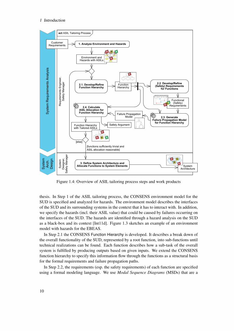
Figure 1.4 shows the process steps and created/required work products of the ASILtailoring process as a UML activity diagram [Obj15b]. The left of the figure is annotatedwith the corresponding early system phases of the V model (cf. Figure 1.1) in which theprocess steps are executed and the responsible roles.
In the early system phases, systems engineering methods are applied. Thus, the ASILtailoring process needs to be integrated with such a method. As an example of an establishedmodel-based systems engineering method, we use CONSENS [GRS14, Sect. 4.1] in this
9
1 Introduction
Sys
tem
Req
uire
men
ts A
naly
sis
Sys
tem
A
rch.
D
esig
n
act ASIL Tailoring Process
Sys
tem
D
esig
ner,
S
afet
y M
anag
er
1. Analyze Environment and Hazards
2.3. GenerateFailure Propagation Model
for Function Hierarchy
2.4. CalculateASIL Allocation forFunction Hierarchy
2.2. Develop/Refine(Safety) Requirements
for Functions
3. Define System Architecture andAllocate Functions to System Elements
2.1. Develop/RefineFunction Hierarchy
[else]
CustomerRequirements
SystemArchitecture
FunctionHierarchy
Functional(Safety)
Requirements
Failure PropagationModel
Function Hierarchywith Tailored ASILs
Environment andHazards with ASILs
Req
uire
men
ts E
ngin
eer,
Saf
ety
Man
ager
[functions sufficiently trivial and ASIL allocation reasonable]
Safety Argument
Figure 1.4: Overview of ASIL tailoring process steps and work products
thesis. In Step 1 of the ASIL tailoring process, the CONSENS environment model for theSUD is specified and analyzed for hazards. The environment model describes the interfacesof the SUD and its surrounding systems in the context that it has to interact with. In addition,we specify the hazards (incl. their ASIL value) that could be caused by failures occurring onthe interfaces of the SUD. The hazards are identified through a hazard analysis on the SUDas a black-box and its context [Int11d]. Figure 1.3 sketches an example of an environmentmodel with hazards for the EBEAS.
In Step 2.1 the CONSENS Function Hierarchy is developed. It describes a break down ofthe overall functionality of the SUD, represented by a root function, into sub-functions untiltechnical realizations can be found. Each function describes how a sub-task of the overallsystem is fulfilled by producing outputs based on given inputs. We extend the CONSENSfunction hierarchy to specify this information flow through the functions as a structural basisfor the formal requirements and failure propagation paths.
In Step 2.2, the requirements (esp. the safety requirements) of each function are specifiedusing a formal modeling language. We use Modal Sequence Diagrams (MSDs) that are a
10

1.4 Thesis Structure
formal, scenario-based requirements language based on UML sequence diagrams [HM08;Gre11; HFK+16]. Requirements specified in this language can automatically be processedto identify failure propagation paths.
To find possible ASIL tailoring solutions and to verify that an applied tailoring meets itssafety requirements, safety analyses have to be performed. As requirements are iterativelyrefined while developing the function hierarchy and applying ASIL tailoring, and becauseof the safety requirements engineering dilemma, the safety analyses should require onlyreasonable effort. Thus, in the automated Step 2.3, the safety manager generates a FailurePropagation Model based on fault trees to be used for safety analysis. The failure propagationmodel is generated from the structure of the function hierarchy and the behavior describedin the formal functional (safety) requirements. The failure propagation model is used tocalculate valid, tailored ASIL values for the functions of the function hierarchy in theautomated Step 2.4. Also in Step 2.4, a safety argument is constructed that connects andtraces the work products of the ASIL tailoring process to maintain a safety case in form ofa model using the Goal Structuring Notation (GSN) [Ass18] as suggested by ISO 26262[Int12b].
The steps 2.1 to 2.4 are iterated until the tailored ASILs of the functions meet the safetymanager’s expectations and the detail level of the functions is sufficiently trivial to be realizedby technical elements of the System Architecture.
In the final Step 3, the system architecture is defined by the system designer [She96](as CONSENS active structure) and the functions are allocated to their realizing systemelements. Afterward, the functional safety requirements of the functions are refined intotechnical safety requirements [Int11e] that have to be satisfied by the system elements thatthe functions have been allocated to. Following, safety analyses on the system architecturehave to be performed to show that the ASIL tailoring on functional level remains valid on thesystem level.
1.4 Thesis Structure
This thesis is structured as follows. Chapter 2 provides the foundations for the followingchapters. Chapter 3 describes the ASIL tailoring process in detail. In Chapter 4, the languageand method for specifying formal functional (safety) requirements and the integrationwith natural language requirements are explained. Chapter 5 goes into detail on thegeneration of the failure propagation model and its usage for ASIL allocation to functions.Chapter 6 describes the construction of model-based safety arguments. The prototypicalimplementation and evaluation of the approach are explained in Chapter 7. Chapter 8concludes the thesis. In addition, Appendix A contains details on the models used for theevaluation and Appendix B on my paper contributions.
11


2
FOUNDATIONS
This chapter introduces the terms, languages, and methods that are necessary to understandthe concepts presented in this thesis. Section 2.1 introduces the development process forcyber-physical systems underlying the approach of this thesis. In Section 2.2, the automotivesafety standard ISO 26262 is introduced. Section 2.3 gives on overview of other safetystandards and their safety integrity levels. In Section 2.4, the basics of safety analysisusing fault trees are explained. Section 2.5 describes the two ASIL tailoring measuresdefined by ISO 26262. The sections 2.6, 2.7, and 2.8 give an overview of the model-based systems engineering method CONSENS, Modal Sequence Diagrams, and the GoalStructuring Notation, respectively.
2.1 Development Process for Safe Cyber-Physical Systems
Cyber-physical systems [Aca11] are characterized by their complex functionality andcommunication with other systems and surroundings. They have evolved from mechatronicsystems that are comprised of mechanical, electric/electronic, and software parts. Thedevelopment of such complex systems requires the application of systems engineering asan interdisciplinary approach and means to enable their successful realization [Int15; Int08].Figure 2.1 shows the development process for mechatronic systems of VDI 2206 [VDI04]following the V model. Especially in its phase of system design interdisciplinary systemsengineering methods like CONSENS (cf. Section 2.6) are applied. Based on requirements asystem architecture is designed that forms the common ground for development in discipline-specific design. The discipline-specific design is split up into the disciplines of mechanicalengineering for mechanical system parts, electrical engineering for electric/electronic systemparts, and information technology for software parts. Afterward, system-level test andintegration is done in the phase of system integration resulting in the final product.
The complexity of cyber-physical systems also implies complexity of their requirements.Hence, their development requires the application of thorough requirements engineering[Int11i; IG14]: “Requirements engineering is concerned with discovering, eliciting,developing, analyzing, determining verification methods, validating, communicating,documenting, and managing requirements” [Int11i]. Automotive SPICE [Aut10] is aspecialization of the general process maturity model SPICE [Int12a] for the automotivedomain. Its development process is shown in Figure 2.2. In contrast to VDI 2206, itdecomposes the phase of system design into two phases to explicitly account for requirementsengineering: Its phase of ENG.2 system requirements analysis precedes the phase of
13

2 Foundations
Assurance of Properties
System Design
Discipline-specific Design
Electrical EngineeringInformation Technology
Modeling and Analysis
Mechanical Engineering
Requirements Product
Syst
em In
tegr
atio
n
Figure 2.1: VDI 2206 V model [VDI04]
Customer Requirements
ENG.3System
Architectural Design
ENG.4 Software
Requirements Analysis
ENG.8 Software Testing
ENG.7 Software
Integration Test
Product
ENG.5 Software Design
ENG.10System Testing
ENG.2System
Requirements Analysis
ENG.9System
Integration Test
ENG.6 Software Construction Software Unit Testing
Figure 2.2: Automotive SPICE V model
14

2.1 Development Process for Safe Cyber-Physical Systems
ENG.3 system architectural design. After these two system-level phases, Automotive SPICEfocuses on the software development phases ENG.4 to ENG.8 (cf. information technology inVDI 2206). Finally, it also splits the phase called system integration in VDI 2206 into twophases ENG.9 system integration test and ENG.10 system testing, in order to distinguishtests against the system architecture and against the system requirements as specified in thefirst two phases on the left side of the V model.
The development of safe cyber-physical systems requires the application of safetyengineering throughout the whole development process: “System safety engineering isa compilation of engineering analyses and management practices that control dangeroussituations” [Bah14]. This are activities to
• identify the hazards in a system,• determine the underlying causes of those hazards,• develop engineering or management controls to either eliminate the hazards or mitigate
their consequences,• verify that the controls are adequate and in place, and• monitor the system after it has been changed and modify further as needed [Bah14].
Figure 2.3 shows an excerpt of the development process as prescribed by the automotivesafety standard ISO 26262 [Int11f] (cf. Section 2.2). The excerpt focuses on the system andsoftware phases related to Automotive SPICE as shown in Figure 2.2. The number to theleft of each phase references the according section of the standard (3-x [Int11d], 4-x [Int11e],6-x [Int11f]). In phases 3-8 and 4-6 system-level safety requirements are specified (i.e.,functional safety requirements and technical safety requirements, cf. Section 2.2). Hence,these phases can be integrated with phase ENG.2 of Automotive SPICE. The phase 4-7adds safety engineering measures to the system architectural design phase ENG.3. Thephase 4-8 adds safety engineering measures to the system-level test and integration phasesENG.9 and ENG.10. The phases 6-6 to 6-11 add safety engineering measures to the softwaredevelopment phases ENG.4 to ENG.8.
In conclusion, the development of safe cyber-physical systems requires sophisticatedmethods for systems, requirements, and safety engineering in sync with developmentprocesses as demanded by standards like VDI 2206, Automotive SPICE, and ISO 26262.Figure 2.4 shows an interdisciplinary development process that integrates the views of thosethree standards. Customer requirements are the initial input to the development process andspecifically to the system requirements analysis phase. The output of that phase are systemrequirements that include the functional and technical safety requirements of ISO 26262.Output of the system architectural design is the system architecture that forms the basisfor the discipline-specific phases of mechanical, electric/electronic (E/E), and softwareengineering. The discipline-specific integration and test phases are followed by systemintegration test and system test. Finally, the cyber-physical system is the product of thedevelopment process.
In such a development process many persons are involved. They assume one or severalroles that are responsible for the tasks of the different development phases. Figure 2.5 showsthe roles that are relevant for the remainder of this thesis.
15

2 Foundations
Item testing
Software testing
Software testing
Software testingSoftware unit design and implementation6-8
Specification ofsoftware safety requirements6-6 Verification of
software safety requirements6-11
Software architectural design6-7 Software integration and testing6-10
Software unit testing6-9
System design4-7
Specification oftechnical safety requirements4-6
Functional safety concept3-8
Item integration and testing4-8
Figure 2.3: ISO 26262 V model
SystemRequirements Analysis
SystemArchitectural Design
Req.Analys.
SWE/EMech.
SWDesign
SW Construction SW Unit-Testing
SWIntegr.
SWTest
Test
SystemIntegration Test
SystemTest
CustomerRequirements Product
……
Verification
Verification
Verification
Verification
Verification
Figure 2.4: Interdisciplinary development process for cyber-physical systems
16

2.1 Development Process for Safe Cyber-Physical Systems
Safety Manager
Requirements Engineer
System Designer
System Requirements
Engineer
Software Requirements
Engineer
Role
Engineer
Mechanical Engineer
Electrical Engineer
Software Engineer
0..*
delegatesSafetyTasksTo
Figure 2.5: Roles in the development process
DEFINITION 2.1 (SAFETY MANAGER)“The safety manager shall be responsible for the planning and coordination of the functionalsafety activities in the development phases of the safety lifecycle” [Int11c]. “The safetymanager can delegate tasks to persons that possess the required skills, competences andqualifications” [Int11c]. The safety manager is responsible for the safety activities (Def. 2.8;e.g., safety analysis) and safety work products (e.g., hazards, safety requirements, and safetycase).
In this thesis, whenever we refer to the safety manager doing something, like e.g., writingsafety requirements, it is possible that he/she actually delegates that task to a requirementsengineer.DEFINITION 2.2 (REQUIREMENTS ENGINEER)The requirements engineer is a person who – in collaboration with stakeholders – elicits,documents, validates, and manages requirements [IG14].
DEFINITION 2.3 (SYSTEM REQUIREMENTS ENGINEER)The system requirements engineer is a requirements engineer that is responsible for system-level requirements engineering (i.e., the system requirements analysis phase) and workproducts (e.g., functional requirements and function hierarchy). We consider this role asynonym for the requirements owner defined by Sheard [She96] and used in the integratedsystem and software development process for cyber-physical systems of Holtmann et al.[HBM+16].
DEFINITION 2.4 (SOFTWARE REQUIREMENTS ENGINEER)The software requirements engineer is a requirements engineer that is responsible forsoftware-specific requirements engineering (i.e., the software requirements analysis phase)as described by Holtmann et al. [HBM+16].
17
2 Foundations
DEFINITION 2.5 (SYSTEM DESIGNER)The system designer is responsible for the phase of system architectural design and thesystem architecture as defined by Sheard [She96] and used by Holtmann et al. [HBM+16].
For simplicity, we compile all discipline-specific tasks into the roles mechanical engineer,electrical engineer, and software engineer in this thesis (except for the software requirementsengineer, cf. Definition 2.4). We consider these roles responsible for discipline-specificdesign, implementation, and test.
2.2 Automotive Safety Standard ISO 26262
“ISO 26262 is the adaptation of IEC 61508 [Int10a] to comply with needs specific tothe application sector of electrical and/or electronic (E/E) systems within road vehicles.ISO 26262 is intended to be applied to safety-related systems that include one or moreelectrical and/or electronic (E/E) systems and that are installed in series production passengercars with a maximum gross vehicle mass up to 3.5 t.” [Int11a]
In general, ISO 26262 specifies what safety measures (cf. Definition 2.6) have to be takento develop, produce, and operate a safe vehicle.
DEFINITION 2.6 (SAFETY MEASURE)A safety measure is a safety activity (Def. 2.8) or safety mechanism (Def. 2.7) to avoid orcontrol systematic failures and to detect or control random hardware failures, or mitigatetheir harmful effects [Int11a].
DEFINITION 2.7 (SAFETY MECHANISM)A safety mechanism is a technical solution implemented by E/E functions or elements, or byother technologies, to detect faults or control failures in order to achieve or maintain a safestate [Int11a].
DEFINITION 2.8 (SAFETY ACTIVITY)A safety activity is an activity performed in one or more subphases of the safety life cycle[Int11a]. Examples are the HARA (Def. 2.12) and safety analyses (Def. 2.9) like FMEA.
DEFINITION 2.9 (SAFETY ANALYSIS)“The objective of safety analyses is to examine the consequences of faults and failures onthe functions, behaviour and design of items and elements. Safety analyses also provideinformation on conditions and causes that could lead to the violation of a safety goal orsafety requirement.” [Int11h]Safety analyses include FMEA and FTA [Int11h].
ISO 26262 consists of the nine normative Parts 1 to 9 and an informative Part 10. Part 1defines the terms used throughout the standard. In Part 2, a safety life cycle from the conceptphase (Part 3), over development (Parts 4 to 6), to the phases of production, operation,service, and decommissioning (Part 7) is defined. Part 8 specifies requirements on supportingprocesses like configuration and change management. Part 9 contains requirements on safetyanalyses and defines the rules for ASIL tailoring (cf. Section 2.5). The informative Part 10provides a guideline on the standard, e.g., concerning its understanding and the specificationof a safety case (cf. Definition 2.10).
18

2.2 Automotive Safety Standard ISO 26262
DEFINITION 2.10 (SAFETY CASE)The safety case is “an argument that the safety requirements for an item are complete andsatisfied by evidence compiled from work products of the safety activities [Def. 2.8] duringdevelopment” [Int11a]. “The safety case should progressively compile the work productsthat are generated during the safety lifecycle” [Int11c].
The left of Figure 2.6 shows an excerpt from the concept and development phases ofISO 26262 annotated with the respective part (and section) number. In ISO 26262, thesystem under development is called item. During item definition the system boundary isdefined, i.e., what is part of the item and what is part of its environment. Afterward, duringhazard analysis & risk assessment (cf. Definition 2.12), hazards (cf. Definition 2.11) ofthe item are identified, and their risk is determined and specified in form of an ASIL value(Automotive Safety Integrity Level). ASIL values are ranging from ASIL D to ASIL A (indecreasing order) and QM for non-safety-critical elements.
DEFINITION 2.11 (HAZARD)A hazard is a potential source of physical injury or damage to the health of persons [Int11a].
DEFINITION 2.12 (HAZARD ANALYSIS & RISK ASSESSMENT)Hazard Analysis & Risk Assessment (HARA) is “a method to identify and categorizehazardous events of items and to specify safety goals and ASILs related to the preventionor mitigation of the associated hazards in order to avoid unreasonable risk” [Int11a].
In general, the risk of a hazard is defined as the combination of its likelihood of occurrenceand the severity if the hazard occurs (Risk = Likelihood × Severity). In ISO 26262, thelikelihood is approximated by exposure (e.g., how often is the system in situations wherethe hazard could occur) and controllability (in how far can the hazard be avoided by timelyreactions of involved persons). Hence, the ASIL of a hazard is determined by the threemetrics exposure, controllability, and severity:ASIL = Risk = Likelihood × Severity = (Exposure × Non-Controllability) × Severity.
From the identified hazards, so-called Safety Goals are derived that represent top-levelrequirements to prevent or mitigate the hazards. Each safety goal inherits the ASIL assignedto the corresponding hazard. During the definition of the functional safety concept, the safetygoals are refined into Functional Safety Requirements (FSRs) specified on a PreliminaryArchitecture. Each functional safety requirement inherits the maximum ASIL of the safetygoals it refines.
During product development on system level, the functional safety requirements arerefined into Technical Safety Requirements (TSRs) that specify requirements on thediscipline-spanning System Design. Each technical safety requirement inherits themaximum ASIL of the functional safety requirements it refines. During product developmenton hardware level, technical safety requirements are refined into Hardware SafetyRequirements that specify requirements on the Hardware Detailed Design. Each hardwaresafety requirement inherits the maximum ASIL of the technical safety requirementsit refines. Similarly, during product development on software level, technical safetyrequirements are refined into Software Safety Requirements that specify requirements onthe Software Architectural Design. Each software safety requirement inherits the maximumASIL of the technical safety requirements it refines.
19

2 Foundations
Fu
nctio
na
lsa
fety con
cept
3-8
Ha
zard an
alysisan
d ris
k assess
men
t3-7
Item d
efinitio
n3-5
Pro
du
ct d
evelo
pm
en
tS
ystem
level
4Ha
rdw
are
level
5S
oftw
are
level
6
OptionalSafety Analyses
RequiredSafety Analyses
Haza
rds
with
AS
IL
Safety
Go
als
Fu
nctio
nal
Safety
Req
uirem
ents
derivedFrom
refine
refine
refinerefine
Prelim
inary
Arch
itecture
System
Desig
n
Hard
ware
Detailed
Desig
n
So
ftware
Arch
itectural
Desig
n
satisfies
satisfies
satisfiessatisfies
Tech
nical
Safety
Req
uirem
ents
Hard
ware
Safety
Req
uirem
ents
So
ftware
Safety
Req
uirem
ents
ASIL
Propagation
Figure2.6:E
xcerptofISO26262
safetylife
cyclephases
with
work
productsand
ASIL
propagation
20

2.2 Automotive Safety Standard ISO 26262
Safety analyses support the safety manager to identify failures and failure propagationpaths through the system, and, thus, to define corresponding safety requirements. ISO 26262requires to apply safety analyses in the product development phases 4 to 6. In the earlierphases 3-5 to 3-8 they are only considered optional.
As a refinement of Figure 1.1 on page 2, the red, thick arrows in Figure 2.6 highlightthe ASIL propagation. Each ASIL value is initially determined for an identified hazard,and propagates over the different safety requirement abstraction levels to the correspondingsystem-level and discipline-specific designs. Based on the ASIL of a requirement or designelement, ISO 26262 requires the application of safety measures (cf. Definition 2.6) ofdifferent sophistication and effort. Hence, a high ASIL that propagates through all phasesresults in a high safety effort.
The term “functional”The term “functional” has several meanings in the different fields we touch in this thesis:We have to distinguish functional safety, functional safety requirement, and (non-)functionalrequirement. Functional safety is concerned with safe system behavior (cf. Definition 2.13).Functional safety requirements (cf. Definition 2.14), technical safety requirements, andhardware/software safety requirements denote the three safety requirement abstractionlevels used in ISO 26262 (cf. Figure 2.6). Orthogonal to that definition, in requirementsengineering, functional requirements (cf. Definition 2.15) and non-functional requirements(cf. Definition 2.16) are terms used to distinguish requirements on behavior and requirementson quality [IG14].
DEFINITION 2.13 (FUNCTIONAL SAFETY)Functional safety is the absence of unreasonable risk due to hazards caused bymalfunctioning behavior of a system [Int11a].
DEFINITION 2.14 (FUNCTIONAL SAFETY REQUIREMENT)A functional safety requirement is the specification of an implementation-independent safetybehavior, or an implementation-independent safety measure (Def. 2.6) [Int11a].
DEFINITION 2.15 (FUNCTIONAL REQUIREMENT)A functional requirement is “a requirement concerning a result of behavior that shall beprovided by a function of a system” [IG14].
DEFINITION 2.16 (NON-FUNCTIONAL REQUIREMENT)A non-functional requirement is “a quality requirement or a constraint” [IG14].
In this thesis, we use the abbreviated, general term “safety” instead of “functional safety”(cf. Definition 2.13) to not confuse the reader with the other meanings of “functional”. Weuse the term “functional” to refer to the abstraction level of functional safety requirements (cf.Definition 2.14) and corresponding functions of a preliminary architecture (e.g., CONSENSfunction hierarchy, cf. Section 2.6). We use the term “functional requirement” to refer to non-safety requirements on the ISO 26262 abstraction level of functional safety requirements.In conclusion, in this thesis, functional requirements are requirements on the functionalabstraction level that can be related to behavior, quality, or constraints, and functional safetyrequirements are the same but specifically concerned with safety.
21

2 Foundations
2.3 Safety Integrity Levels in other Safety Standards
ISO 26262 is a safety standard specifically for the automotive domain. It is derived fromthe base standard IEC 61508 [Int10a]. IEC 61508 defines five safety integrity levels (SIL)ranging from SIL 0 (non-safety-critical) to SIL 4 (highly safety-critical). ISO 26262 alsodefines five safety integrity levels, called Automotive Safety Integrity Levels (ASIL), rangingfrom QM, over ASIL A, to ASIL D.
Many domains have derived their own safety standard from IEC 61508. The railwaydomain derived their standard EN 50128 [CEN11] adopting the same five SILs of IEC 61508.So did mechanical and plant engineering with IEC 62061 [Int05]. The safety standard foragricultural vehicles ISO 25119 [Int10b] is also derived from IEC 61508 but uses their ownfive safety integrity levels, called Agriculture Performance Levels (AgPL), ranging fromAgPL a to AgPL e. There are further domains with standards derived from IEC 61508.
Apart from domains basing on IEC 61508 there are other domains that defined safetystandards on their own. For instance, in the aerospace domain ARP4754A definesDevelopment Assurance Levels (DAL) [SAE10]. These are also comprised of five valuesranging from DAL E (lowest) to DAL A (highest).
Blanquart et al. compared the safety standards of different domains [BAB+12]. Eachstandard they considered uses some kind of safety integrity levels and the risk assessment isbased on (a derivation of) the basic principle Risk = Likelihood × Severity.
2.4 Safety Analysis using Fault Trees
The objective of safety analysis is to examine the consequences of failures on the functions,behavior and design of a system and its elements (cf. Definition 2.9). In this thesis, weconsider the following kinds of failures:
DEFINITION 2.17 (SINGLE-POINT FAILURE)A single-point failure is a failure that results from one fault and leads directly to the violationof a safety goal (i.e., the occurrence of a hazard) [Int11a].
DEFINITION 2.18 (MULTIPLE-POINT FAILURE)A multiple-point failure is a failure resulting from the combination of several independentfaults that leads directly to the violation of a safety goal (i.e., the occurrence of a hazard)[Int11a].
DEFINITION 2.19 (DUAL-POINT FAILURE)A dual-point failure is a multiple-point failure resulting from the combination of twoindependent faults that leads directly to the violation of a safety goal (i.e., the occurrenceof a hazard) [Int11a].
DEFINITION 2.20 (DEPENDENT FAILURES)Dependent failures are failures whose probability of simultaneous or successive occurrencecannot be expressed as the simple product of the unconditional probabilities of each of them(PAB 6= PA × PB). [Int11a]
DEFINITION 2.21 (CASCADING FAILURE)A cascading failure (CF) is a dependent failure (Def. 2.20) of an element causing one or moreother elements to fail [Int11a].
22

2.4 Safety Analysis using Fault Trees
DEFINITION 2.22 (COMMON CAUSE FAILURES)Common cause failures (CCFs) are dependent failures (Def. 2.20) of two or more elementsresulting from a single specific event or root cause [Int11a].
Fault trees can be used to specify the correlation of subsystem failures and events leadingto a failure or hazard of the overall system. The following Section 2.4.1 briefly introducestheir notation and use. Section 2.4.2 explains an adaptation of the fault tree notation for usein hierarchically structured models like component-oriented architectures.
2.4.1 Fault Tree Analysis (FTA)
Fault tree analysis (FTA) [Int06b] is a deductive safety analysis used to identify the possiblecauses of an event (e.g., a failure). Figure 2.7 shows an example fault tree. Its rootnode Omission of activateEmergencyBraking is a top-event denoted by a rectangle. Itrepresents the failure that the activation of emergency braking is omitted. In deductivefault tree analysis, this event is decomposed into sub-events that lead to its occurrence.Beside events, fault trees can also contain OR gates and AND gates. In the figure, thetop-event occurs if the basic event Crash (denoted by a circle) occurs OR the eventsOmission of reachingLastPointToBrake AND Omission of receivedEmcyBrakeWarning occursimultaneously. The latter two events are top-events in other fault trees that are referenced inthis fault tree by the triangle notation. On the contrary, basic events are events that are notrefined by any subtree of gates and events.
Crash
OR
AND
Omission of activateEmergency
Braking Top-event
Gates
Basic event
Subtree reference
Omission of reachingLast
PointToBrake
Omission of receivedEmcyBrakeWarning
Figure 2.7: Example fault free
Once a fault tree is specified, it is analyzed for so-called minimal cut sets. They describeminimal sets of fault tree leaf nodes (typically basic events) whose simultaneous occurrenceleads to the occurrence of the top-event. Figure 2.7 contains the two minimal cut sets {Crash}and {Omission of reachingLastPointToBrake, Omission of receivedEmcyBrakeWarning}.
23

2 Foundations
2.4.2 Component Fault Trees (CFTs)
In classical fault tree analysis, for each hazard of a system, a fault tree with the hazardoccurrence as top-event is specified. If fault tree diagrams get too large to grasp, subtreesare described in separate fault trees and referenced by the triangle notation (cf. Figure 2.7).The classical fault tree notation has no defined traceability to a system, its components, orcomponent interfaces. Furthermore, fault trees relating to the same system usually havecommon subtrees whose consistency has to be maintained if the system changes.
To overcome these disadvantages, Kaiser et al. developed Component Fault Trees (CFTs)that decompose classical fault trees into reusable components that can directly relate tocomponents of a system [KLM03; HTZ+12]. Figure 2.8 shows a CFT representation ofthe fault tree from Figure 2.7. A CFT is represented by a rectangle with the keyword “CFT”in the top left followed by the name of the CFT (e.g., MakeDecisionCFT in Figure 2.8).The internal CFT syntax closely follows the syntax of classical fault trees. The trianglenotation is used to connect different CFTs. Like UML ports, the triangles are placed on theborder of the CFT. So-called input failure modes (similar to subtree references in classicalfault trees) are denoted by white triangles, and output failure modes (relating to input failuremodes of other CFTs) by black triangles. Figure 2.8 shows the advantage of this notation:The crash and omission input failure modes result in the output failure mode Omission ofactivateEmergencyBraking, as denoted in the classical fault tree of Figure 2.7. However,they also result in the output failure mode Omission of sendEmcyBrakeWarning. In classicalfault tree analysis, this would need to be specified by two separate fault trees that only differin their top-event and have to be kept in sync.
2.5 ASIL Tailoring
As a high ASIL requires a high degree of rigor that implies high development effort, there isa demand to reduce the amount of high ASIL requirements and subsystems. ASIL tailoringis a means to reduce the ASIL of parts of the system by separation and decomposition. Theautomotive safety standard ISO 26262 defines rules that a tailoring has to obey [Int11h]. Therules describe under what conditions a specific ASIL value of a safety requirement (and itssatisfying subsystem) may be reduced and to what value. Safety standards for other domains(cf. Section 2.3) have similar rules, e.g., ARP4754A for aerospace.
The following sections describe the two ASIL tailoring measures separation(Section 2.5.1) and decomposition (Section 2.5.2) and the according rules by example.
2.5.1 Separation
The first ASIL tailoring option to reduce the development effort is to separate subsystemswith different levels of safety-criticality (i.e., with different ASIL values). If one canmake sure that a less safety-critical subsystem will not interfere with a more safety-criticalsubsystem, i.e., that a failure of the less critical subsystem will not cause a failure of the morecritical subsystem violating a more critical safety requirement (i.e., causing a more criticalhazard), the two subsystems are considered separate and may have different ASIL valuesassigned [Int11h, Clause 6].
24

2.5 ASIL Tailoring
CFTMakeDecisionCFT
Crash
OR
AND
Outputfailure modes
Inputfailure modes
Omission ofsendEmcyBrakeWarning
Omission of reachingLast
PointToBrake
Omission of receivedEmcyBrakeWarning
Omission of activateEmergency
Braking
Figure 2.8: Example Component Fault Tree
DEFINITION 2.23 (FREEDOM FROM INTERFERENCE)An element a is free of interference from an element b if there are no cascading failures(Def. 2.21) from b to a that could lead to the violation of a safety requirement [Int11a].
DEFINITION 2.24 (ASIL SEPARATION)ASIL separation is the act of apportioning safety requirements to sub-elements of an element,with the objective of reducing the ASIL of sub-elements that do not interfere (Def. 2.23) withsub-elements with higher ASIL safety requirements.
Figure 2.9 depicts the separation of the EBEAS and the Body Control Module. The lattercontrols the brake lights and turn signals and does not send any information to the EBEAS.Thus it seems likely, that it’s malfunction will not cause the EBEAS to fail as well.
Table 2.1 sketches the safety requirements for the two systems. The Body Control Moduleby itself only causes ASIL B hazards, and thus, has to fulfill ASIL B safety requirementsonly (SR1 ff.). The EBEAS is highly safety-critial (cf., ASIL D hazards in Figure 1.3 onpage 4), and thus, has to fulfill some ASIL D requirements (SR42 ff.). For the EBEASscenario, the Body Control Module is connected to the EBEAS. In general, this would requireto increase the ASIL value of the Body Control Module to ASIL D as well. This wouldincrease the safety effort significantly, as the whole Body Control Module would need to beredeveloped applying all the safety measures required for ASIL D systems. If the safetyanalysis shows that no failure of the Body Control Module propagates to the EBEAS leading
25

2 Foundations
SR42,…,68, ASIL D
EBEAS
BodyControlModule
ASIL B
ASIL D
SR69, ASIL D
X
SR1,…,41, ASIL B
Figure 2.9: ASIL tailoring measure: Separation
to the violation of ASIL C or D requirements (safety requirement SR69), the ASIL of theBody Control Module does not need to be increased.
Table 2.1: Requirements for separation
ID Description ASIL
SR1 The Body Control Module shall. . . ASIL B. . . . . . . . .
SR42 The EBEAS shall. . . ASIL D. . . . . . . . .
SR69 There shall not be any cascading failures from the Body Control Moduleto the EBEAS.
ASIL D
2.5.2 Decomposition
The second ASIL tailoring option to reduce the development effort is to decompose asystem’s highly safety-critical requirement into redundant, less critical safety requirementsthat are realized by independent subsystems [Int11h, Clause 5]. By adding redundancy inthis way, two systems would have to fail at the same time (dual-point-failure), in order forthe addressed hazard to occur.
DEFINITION 2.25 (INDEPENDENCE)Two or more elements are independent if there are no dependent failures (Def. 2.20) betweenthem that could lead to the violation of a safety requirement [Int11a].
DEFINITION 2.26 (ASIL DECOMPOSITION)ASIL decomposition is the act of apportioning safety requirements redundantly to sufficientlyindependent elements (Def. 2.25), with the objective of reducing the ASIL of the redundantsafety requirements that are allocated to the corresponding elements [Int11a].
Figure 2.10 and Table 2.2 depict an example of an ASIL D requirement SR2 that isdecomposed into lower ASIL requirements SR2.1 and SR2.2 in order to keep the ASILof the two systems Adaptive Cruise Control and Vehicle2X Communication lower than
26

2.5 ASIL Tailoring
the ASIL of the EBEAS. The EBEAS can cause the hazards of missing brake activationand missing steering for evasion (cf., hazards H1 and H3 in Figure 1.3 on page 4). Theaccording safety requirement SR1 shall avoid these hazards and thus inherits their ASILvalue of ASIL D. If the EBEAS shall activate the brakes or steering, it needs to get theinformation whether the leading vehicle is braking to make a decision. This is stated inrequirement SR2 which accordingly also inherits ASIL D. The leading vehicle sends anemergency brake warning via a vehicle-to-vehicle message. So, SR2 would be realized bythe Vehicle2X Communication that thus would inherit the ASIL D of the requirement. Asdescribed in Section 1.1, the Vehicle2X Communication has a predetermined ASIL value ofQM. So, the increase to ASIL D would result in high development effort. In addition to thevehicle-to-vehicle message, the braking of the leading vehicle can also be detected by thesensors of the Adaptive Cruise Control. This means that there are two redundant sourcesof information. This fact can be exploited for requirements decomposition with respect toASIL tailoring. The requirement SR2 is decomposed into the two redundant requirementsSR2.1 and SR2.2 that are allocated to the Vehicle2X Communication and the Adaptive CruiseControl, respectively. Consequently, the two systems would have to fail at the same time, inorder for one of the hazards H1 and H3 to occur (cf., the AND-gate in Figure 2.10). To makesure that the two systems do not fail for the same reason, the three safety requirements SR2.3
to SR2.5 are added.
SR1, ASIL D
EBEAS
ElectronicStabilityControl
AdaptiveCruiseControl
Vehicle2XCommunicationASIL D
SR2.2, ASIL C(D)
SR2.1, ASIL A(D)
Sensed nohard braking
Received nobrake warning
ASIL C(D)
ASIL A(D)
ASIL D
SR2.3,2.4,2.5, ASIL D
AND
No brake activation
No evasive steering
Figure 2.10: ASIL tailoring measure: Introduction of redundancy
As there are two systems that redundantly satisfy the original safety requirement SR2, thesafety standard ISO 26262 allows to develop each of the systems with a lower degree of rigorthan the original requirement’s ASIL value requires. But in sum, the applied rigor has to stillmeet the original ASIL. This can be shown by applying simple arithmetics: each ASIL valueis assigned with a number from 0 to 4 and the sum of the decomposed ASIL values needsto reach the original ASIL value [APW+14]. In the example, SR2.1 is assigned with theASIL value ASIL A and SR2.2 with ASIL C, which adds up to ASIL D (1 + 3 = 4). Whenapplying this decomposition ASIL tailoring method, ISO 26262 still requires to apply somesafety measures in accordance with the original ASIL, especially in the integration phases.
27

2 Foundations
Table 2.2: Requirements decomposition for ASIL tailoring
ID Description ASIL
SR1 If the EBEAS determines the leading vehicle’s hard braking, theEBEAS shall execute an emergency braking or evasion maneuver.
ASIL D
SR2 If the leading vehicle brakes hard, the EBEAS shall be informed. ASIL D
SR2.1 If the Vehicle2X Communication receives a hard braking warning, itshall inform the EBEAS.
ASIL A(D)
SR2.2 If the Adaptive Cruise Control senses the leading vehicle’s hardbraking, it shall inform the EBEAS.
ASIL C(D)
SR2.3 There shall not be any cascading failures from the Vehicle2XCommunication to the Adaptive Cruise Control.
ASIL D
SR2.4 There shall not be any cascading failures from the Adaptive CruiseControl to the Vehicle2X Communication.
ASIL D
SR2.5 There shall not be any common cause failures of the Vehicle2XCommunication and the Adaptive Cruise Control.
ASIL D
Thus, the original ASIL value always has to be stated in parentheses (cf., Figure 2.10 andTable 2.2).
In summary, the example contains ASIL D hazards and according safety requirementsfor the EBEAS. The Vehicle2X Communication provides information, whose omission canlead to those hazards occurring and thus would be assigned with ASIL D as well. Thepredetermined ASIL value of the Vehicle2X Communication is only QM, so ASIL D wouldresult in a high development effort. The Adaptive Cruise Control can redundantly providethe same information required by the EBEAS. Its predetermined ASIL value is ASIL C. Bydecomposing the original ASIL D requirement SR2 into an ASIL A(D) requirement for theVehicle2X Communication and an ASIL C(D) requirement for the Adaptive Cruise Control,the latter stays ASIL C and the ASIL value of the Vehicle2X Communication is only increasedone level to ASIL A. Thus, the overall development effort is reduced.
2.6 Model-based Systems Engineering with CONSENS
The CONceptual design Specification technique for the ENgineering of complex Systems(CONSENS) is a model-based systems engineering language and method [GRS14,Section 4.1]. Figure 2.11 sketches its so-called partial models and the process of theircreation. A detailed description of the CONSENS process including the transition to softwareengineering is specified by Holtmann et al. [HBM+16]. Firstly, the system’s environment,its application scenarios, and requirements are specified. These work products merge into afunction hierarchy specifying the functions the system shall provide. Based on the functionhierarchy, the active structure is developed that specifies the system’s internal structure.Afterward, the system’s behavior and shape is specified. Eventually, the partial models serveas input to the mechanical engineering, electrical engineering, and information technologyand their discipline-specific work products (cf. Figure 2.1 on page 14).
28

2.6 Model-based Systems Engineering with CONSENS
Application ScenariosEnvironment Requirements
Discipline-specific Work Products
Function Hierarchy... ... ...
Active Structure
ID
1
2
3
... ...
Ipsum dolor...
Dolor lorem...
Lorem ipsum...
TextLorem ipsum dolor lorem ipsum dolor lorem...Lorem ipsum dolor lorem
ipsum dolor lorem...
ShapeBehavior
Figure 2.11: Simplified CONSENS process with partial models
Instead of the plain CONSENS language, we use SysML4CONSENS [IKD+13;KDH+13] that allows to specify CONSENS partial models based on the Systems ModelingLanguage (SysML) [Obj15a]. SysML provides no systems engineering method but isbased on UML. Hence, using SysML4CONSENS enables a conceptual integration of theCONSENS method with other UML-based methods used in this thesis, and easier technicalintegration using established and extensible UML tool-support (e.g., Eclipse Papyrus1).Figure 2.12 shows the elements of the SysML4CONSENS profile used in this thesis. Weexplain the elements using the following examples of CONSENS partial models.
EnvironmentThe partial model environment is used to specify the system boundary, i.e., the context of thesystem. Figure 2.13 sketches the environment of the EBEAS. The SysML block definitiondiagram (bdd) Environment Types specifies types of system and environment elements, theirports, and their interfaces. The SysML internal block diagram (ibd) Environment specifiesinteractions and connections between the system and its surrounding elements. The systemunder development is marked by the SysML4CONSENS stereotypes System Template andSystem Exemplar, respectively. The elements of the system’s environment are marked by theSysML4CONSENS stereotypes Environment Element Template and Environment ElementExemplar, respectively. In Figure 2.13, the EBEAS is the system under development. Itis screwed to the Vehicle Body via a Screw Connection marked as SysML4CONSENSMechanical Connection. The EBEAS communicates with the Electronic Stability Controlvia a bus system called ADAS Bus. This is realized by exchange of electronic signalsrepresented by the SysML4CONSENS Energy Flow Specification named Adas Bus Signals.Accordingly, both ECUs are connected to the ADAS Bus via ports typed by that energy
1www.eclipse.org/papyrus
29

2 Foundations
«profile» SysML4CONSENS
«Metaclass»Abstraction
«Stereotype»SysML::Block
«Metaclass»Property
«Stereotype»SystemTemplate
«Stereotype»SystemElement
Template
«Stereotype»EnvironmentElement
Template
«Stereotype»SystemExemplar
«Stereotype»SystemElementExemplar
«Stereotype»EnvironmentElement
Exemplar
«Metaclass»Class
«Stereotype»Function
«Stereotype»Realizes
«Stereotype»SysML::InterfaceBlock
«Stereotype»Energy
FlowSpecification
«Stereotype»Information
FlowSpecification
«Metaclass»Connector
«Stereotype»MechanicalConnection
…
Figure 2.12: Excerpt of SysML4CONSENS profile
flow specification. The electronic bus signals are used to exchange information between theEBEAS and the Electronic Stability Control. This is specified by direct port connections typedby SysML4CONSENS Information Flow Specifications. The Electronic Stability Controlsends the current velocity to the EBEAS and the EBEAS sends braking requests to theElectronic Stability Control.
Application ScenariosThe partial model application scenarios is used to specify use cases of the system underdevelopment by informal texts and figures. They do not describe any internal structure orbehavior of the system but its externally visible behavior.
We consider application scenarios an abstract and informal specification of goals for thesystem under development that could be the result of requirements elicitation workshops withthe customer. We see them as part of customer requirements specifications that are the input
30

2.6 Model-based Systems Engineering with CONSENS
«SystemExemplar»:EBEAS
«EnvironmentElementExemplar»
:ElectronicStabilityControl:~EscEcu2EbeasEcu
:~EbeasEcu2EscEcu
:EscEcu2EbeasEcu
:EbeasEcu2EscEcu
«EnvironmentElementExemplar»:ADASBus
:~AdasBusSignals
:~AdasBusSignals
:AdasBusSignals
:AdasBusSignals
bdd Environment Types
ibd Environment
«EnergyFlowSpecification»
AdasBusSignals
out brakingRequest: m/s²
«InformationFlowSpecification»
EbeasEcu2EscEcu
in velocity: km/h
«InformationFlowSpecification»
EscEcu2EbeasEcu
«EnvironmentElementExemplar»
:VehicleBody
«MechanicalConnection»Screw Connection
«SystemTemplate»EBEAS
«EnvironmentElementTemplate»
ElectronicStabilityControl:~EscEcu2EbeasEcu
:~EbeasEcu2EscEcu
:EscEcu2EbeasEcu
:EbeasEcu2EscEcu
«EnvironmentElementTemplate»ADASBus
:~AdasBusSignals
:~AdasBusSignals
:AdasBusSignals
:AdasBusSignals
«EnvironmentElementTemplate»
VehicleBody
Figure 2.13: Example of CONSENS environment
31

2 Foundations
to our approach (cf. Figure 1.4 on page 10). Hence, we do not use application scenarios inthis thesis.
RequirementsThe partial model requirements is a list of textual requirements that refer to elements of otherpartial models (e.g., functions or system elements).
We do not use this partial model in this thesis. Instead, we specify requirements asModal Sequence Diagrams (cf. Section 2.7 and Chapter 4). However, we also integrate ourapproach with textual requirements that could be seen as instantiation of this partial model(cf. Section 4.5).
Function HierarchyThe partial model function hierarchy is used to decompose the functionality that the systemunder development shall provide. The functionality is described by functions that aredecomposed level by level, until they are sufficiently trivial to implement.
Figure 2.14 shows the function hierarchy for the system EBEAS from Figure 2.13.Functions are represented by UML classes marked with the SysML4CONSENS stereotypeFunction. The root node FEBEAS represent the overall functionality of the EBEAS. It isdecomposed into four functions:• The function Analyze Situation shall analyze the vehicles surrounding and velocity,• the function Make Decision shall make the decision to brake or evade,• the function Communicate with other Vehicles shall provide the vehicle-to-vehicle
communication, and• the function Ensure Passenger Safety shall activate the emergency braking or evasion.
«Function»FEBEAS
«Function»AnalyzeSituation
«Function»Communicate
WithOtherVehicles
«Function»Ensure
PassengerSafety
«Function»Make
Decision
bdd Function Hierarchy
Figure 2.14: Example of CONSENS function hierarchy
Active StructureThe partial model active structure is used to specify the internal structure of the systemunder development. Figure 2.15 shows the active structure of the system EBEAS fromFigure 2.13. Elements inside the system under development are called system element byCONSENS. Accordingly, they are marked with the SysML4CONSENS stereotype SystemElement Exemplar (and System Element Template in a corresponding bdd not shown inthe figure). The EBEAS contains the cores Lockstep Cores and Performance Core and thebus interfaces ADAS Bus Interfaces and V2X Bus Interface. Their connections are specified
32

2.6 Model-based Systems Engineering with CONSENS
using ports and SysML4CONSENS flow specifications as it is done in the partial modelenvironment (the details are omitted in Figure 2.15).
In addition, the system elements realize the leaf functions of the function hierarchy. Thisis specified by UML abstractions with the SysML4CONSENS stereotype Realizes. InFigure 2.15, the system element Lockstep Cores realizes the function Make Decision fromFigure 2.14.
«SystemTemplate»EBEAS
«SystemElementExemplar»:LockstepCores
...«SystemElementExemplar»
:V2XBusInterface
«SystemElementExemplar»:PerformanceCore
«SystemElementExemplar»:ADASBusInterfaces
«Realizes»
«Function»Make
Decision
ibd Active Structure
Figure 2.15: Example of CONSENS active structure
BehaviorThe partial model behavior is used to specify the technical behavior of the overall systemand its environment and the internal system elements. This can be done by UML sequencediagrams and state machines.
We specify communication of the overall system with its environment on the functionalabstraction level using the function hierarchy root node and functional representations ofthe environment (cf. Chapter 4). Moreover, we do not specify internal system elementcommunication, as our approach ends with the specification of a system architecturerepresented as active structure. Hence, we do not use the behavior partial model in thisthesis.
ShapeThe partial model shape is used to specify the three dimensional shape of the system underdevelopment. This is not realized by the SysML4CONSENS profile but has to be done in aCAD/CAM tool used by mechanical engineering.
This partial model is not used in this thesis because our approach ends with a systemarchitecture specified as active structure.
33

2 Foundations
2.7 Modal Sequence Diagrams (MSDs)
Modal Sequence Diagrams (MSDs) are a formal, model- and scenario-based behaviorspecification language based on UML sequence diagrams [HM08]. Harel and Maoz definedMSDs to specify provisional and required sequences of events (e.g., message exchange)[HM08]. Greenyer et al. added language features to specify real-time behavior [Gre11;BGH+14]. Holtmann and Meyer adapted MSDs to obey the communication rules ofhierarchically structured component-oriented architectures (e.g., information hiding conceptsusing ports and interfaces) [HM13]. In this thesis, we follow the MSD requirements languagedefinition compiled in the technical report of Holtmann et al. [HFK+16].
Figure 2.16 shows an example of a so-called MSD specification for the EBEAS. Itdescribes message-based interaction behavior of a set of objects. It consists of UML classes,UML collaborations, and MSDs. Classes define the types of objects. Their operations definethe messages an object can receive. In the figure, the EBEAS provides two operationsand the other two ECUs each provide one. Collaborations are used to specify differentsituations, application scenarios, or use-cases of a system. In the figure, the collaborationEBEAS Collaboration contains one role for each type defined in the class diagram. Anothercollaboration based on the same class diagram could, for instance, leave out the Vehicle2XCommunication to specify behavior of the EBEAS without communication. For eachcollaboration a set of MSDs can be specified. Each of their lifelines represents a role fromthe corresponding collaboration.
MSD specifications can be validated by simulation with the so-called play-out algorithm[BGP13]. For that, MSDs add the modalities of execution kind and temperature to messagesof UML sequence diagrams. Monitored messages are represented by a dashed line, executedmessages by a solid line. Cold messages are represented by a blue line, hot messagesby a red line. For readability without color-printing, we annotate the execution kind andtemperature on the side of an MSD using the letters “c”/“h” for cold/hot and “m”/”e” formonitored/executed.
The terms execution kind and temperature are defined based on the play-out of an MSDspecification (i.e., the execution of a set of diagrams). From the point of view of one MSD,a message with execution kind monitored can be observed during the execution of the MSDbut its occurrence is not required. An executed message, on the contrary, is required tooccur during the execution of an MSD. If it is not sent/received, a liveness violation occurs(i.e., a liveness property is violated [Lam77]). In that case, we say the MSD is violated, inthis thesis. A message with temperature cold may be sent/received after any preceding andbefore any subsequent messages of the same MSD, but its execution is not required to occurin this order (it is not strict). If any other message of the same diagram occurs when the coldmessage is expected, a cold violation occurs and the MSD execution is terminated. In thatcase, we say the MSD is discarded, in this thesis. A hot message, on the contrary, has tostrictly occur in the order as specified in the MSD. If any other message of the same diagramoccurs when the hot message is expected, a hot violation occurs that is a violation of a safetyproperty [Lam77]. In that case, we say the MSD is violated, in this thesis.
The play-out algorithm uses so-called cuts to describe the execution state of an MSDspecification. Each MSD has its own cut that progresses from top to bottom and advanceswhenever a message of the diagram occurs. The overall system state is defined by the set of
34

2.7 Modal Sequence Diagrams (MSDs)
receivedEmcyBrakeWarningFromFront()warnedFollowers()
EBEAS
performHardBraking()
ElectronicStabilityControl
warnFollowingVehicle()
Vehicle2XCommunicationcd Classes
EBEAS Collaboration
ebeas: EBEAS
esc: ElectronicStabilityControlv2x: Vehicle2XCommunication
v2x: Vehicle2XCommunication ebeas: EBEAS
receivedEmcyBrakeWarningFromFront
msd R1 Brake on Warning
esc: ElectronicStabilityControl
signature represents
type
abstract syntax link:
(c,m)
(h,e)
(c,e)
v2x: Vehicle2XCommunication ebeas: EBEAS
msd R2 Wait for Warning Response
esc: ElectronicStabilityControl
(c,m)
(h,m)
(c,m)
warnFollowingVehicle
warnFollowingVehicle
performHardBraking
performHardBraking
warnedFollowers
Cut 2
Cut 1
Figure 2.16: Example of an MSD specification
35

2 Foundations
all cuts. Each MSD starts in cut 0 located at the top of the MSD above the first message. Thefirst message of an MSD is called minimal message and is always cold and monitored.
Figure 2.16 contains the two MSDs R1 and R2. R1 specifies the following behavior:if the EBEAS is informed about a received emergency brake warning from a vehicle infront, it warns the following vehicle and afterward performs a hard braking maneuver. R2specifies the behavior that the EBEAS waits for the Vehicle2X Communication to have warnedfollowing vehicles before braking. In the beginning, both MSDs are inactive. If the messagereceivedEmcyBrakeWarningFromFront occurs, the MSD R1 is activated and its cut advancesfrom above that minimal message (cut 0) to cut 1 above the message warnFollowingVehicle.In this state, both messages warnFollowingVehicle and performHardBraking have to occureventually because they are specified as executed. However, because the messagewarnFollowingVehicle is hot, it has to occur before performHardBraking. If it occurs, thecut advances to cut 2 above performHardBraking. In addition, the MSD R2 is activated andits cut advances to cut 1 because warnFollowingVehicle is its minimal message. This stateis depicted by the two cuts in Figure 2.16. In this state, R1 requires performHardBraking tooccur next. However, R2 prohibits this because it also contains that message but its cut isabove the hot message warnedFollowers. Thus, the Vehicle2X Communication has to sendwarnedFollowers before the EBEAS may send performHardBraking. Once warnedFollowersoccurred, the cut of both MSDs is before the message performHardBraking and it may besent. Then, both cuts reached the end of the respective MSD, and the MSDs become inactiveuntil they are again activated by the occurrence of their minimal message.
Additionally to play-out simulation, MSD specifications can be formally verified forconsistency by synthesizing global controllers [GBC+13]. If the MSD R1 in Figure 2.16 alsocontained the message warnedFollowers and the message performHardBraking was hot, thecuts shown in both MSDs could not progress. R1 would require the hot performHardBrakingto occur before warnedFollowers may occur, and R2 still requires the hot warnedFollowers tooccur before performHardBraking. This would be an inconsistency in the MSD specificationthat is found by the controller synthesis.
In addition to messages, MSDs also can contain conditions (represented as hexagon, cf.Figure 3.9 on page 49). A condition contains a boolean expression that is evaluated whenthe MSD execution reaches the condition. The execution kind of conditions is fixed to theirtemperature: a cold condition is always monitored and a hot condition is always executed.For specifying real-time behavior, MSDs can also contain so-called clock conditions. Theseconditions are denoted by an hourglass in their top right (cf. Figure 4.12 on page 79). A clockcondition contains a boolean expression concerning a clock variable that holds the elapsedtime. If the MSD execution reaches a cold (clock) condition and its expression evaluates tofalse, a cold violation occurs and the MSD is discarded. If the MSD execution reaches ahot (clock) condition and its expression never evaluates to true, a liveness violation occurs.If the MSD execution reaches a hot (clock) condition and any other message of the samediagram occurs before its expression evaluates to true, a hot violation occurs. Both cases area violation of the MSD.
36

2.8 Goal Structuring Notation (GSN)
2.8 Goal Structuring Notation (GSN)
The Goal Structuring Notation (GSN) is used to specify model-based argument hierarchies[Kel98; Ass18]. This graphical notation shall support the understanding of complexarguments and reduce the problem of ambiguity in informal textual arguments. GSNarguments follow a tree-like structure of goals that are refined by subgoals using certainargument strategies. The leaf goals are supported by evidence in form of solutions or markedas undeveloped.
Figure 2.17 shows an example argument in Goal Structuring Notation. It argues that allhazards of a system have been mitigated (cf. root goal Goal 1). This goal is in the contextof the identified hazards H1 and H2. The hazards are referenced by the context Hazards,denoted by a rectangle with rounded sides. Context nodes are linked via “in context of” linksdepicted with a white arrow head.
Separate critical components
J
ISO 26262-9:6
Coexistence of elements
Goal 1
Mitigate all hazards
Separate ECU2
Allocate Component2 to ECU2
Separate ECU1
Allocate Component1 to ECU1
No CF
No cascading failures of ECU1 and ECU2
FTA
No failure propagation
Hazards
H1 and H2
Context
Justification
Solution
Goal In Context Of
Strategy
Supported By
Undeveloped Goal
Figure 2.17: Example of an argument in Goal Structuring Notation
Goal 1 is reached by separating safety-critical components. This is specified via thestrategy Separate critical components denoted by a parallelogram. Strategies and goalsare linked via “supported by” links depicted with a black arrow head. The applicabilityof strategies can be argued via justifications denoted as ellipse with a “J” in the lowerright. Justifications are linked via an “in context of” link. In the figure, the applicabilityof the separation strategy is argued via the coexistence of elements section of the standardISO 26262. The strategy Separate critical components is supported by the three subgoals
37

2 Foundations
Separate ECU1, Separate ECU2, and No CF. The first two goals argue that two softwarecomponents Comp1 and Comp2 are allocated to separate ECUs of a vehicle. The third goalNo CF argues that there are no cascading failures (CF) between the two ECUs. The first twogoals are marked as undeveloped via a diamond below the rectangle. Undeveloped goalsrepresent sub-arguments that need to be supported by further subgoals, strategies, and/orsolutions. The goal No CF is supported by the solution FTA denoted by a circle. This solutionshall represent the result of a fault tree analysis, assuring that there is no failure propagationbetween the two ECUs.
38
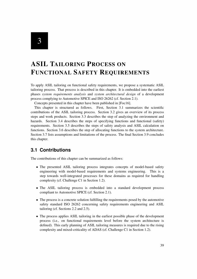
3
ASIL TAILORING PROCESS ONFUNCTIONAL SAFETY REQUIREMENTS
To apply ASIL tailoring on functional safety requirements, we propose a systematic ASILtailoring process. That process is described in this chapter. It is embedded into the earliestphases system requirements analysis and system architectural design of a developmentprocess complying to Automotive SPICE and ISO 26262 (cf. Section 2.1).
Concepts presented in this chapter have been published in [Foc16].This chapter is structured as follows. First, Section 3.1 summarizes the scientific
contributions of the ASIL tailoring process. Section 3.2 gives an overview of its processsteps and work products. Section 3.3 describes the step of analyzing the environment andhazards. Section 3.4 describes the steps of specifying functions and functional (safety)requirements. Section 3.5 describes the steps of safety analysis and ASIL calculation onfunctions. Section 3.6 describes the step of allocating functions to the system architecture.Section 3.7 lists assumptions and limitations of the process. The final Section 3.9 concludesthis chapter.
3.1 Contributions
The contributions of this chapter can be summarized as follows:
• The presented ASIL tailoring process integrates concepts of model-based safetyengineering with model-based requirements and systems engineering. This is astep towards well-integrated processes for these domains as required for handlingcomplexity (cf. Challenge C1 in Section 1.2).
• The ASIL tailoring process is embedded into a standard development processcompliant to Automotive SPICE (cf. Section 2.1).
• The process is a concrete solution fulfilling the requirements posed by the automotivesafety standard ISO 26262 concerning safety requirements engineering and ASILtailoring (cf. Sections 2.2 and 2.5).
• The process applies ASIL tailoring in the earliest possible phase of the developmentprocess (i.e., on functional requirements level before the system architecture isdefined). This early planning of ASIL tailoring measures is required due to the risingcomplexity and mixed-criticality of ADAS (cf. Challenge C1 in Section 1.2).
39

3 ASIL Tailoring Process on Functional Safety Requirements
3.2 Overview of Process Steps and Work Products
The ASIL tailoring process is embedded into the model-based systems engineeringmethod CONSENS (cf. Section 2.6). In CONSENS, based on customer requirements, theenvironment of the SUD is specified, followed by requirements, the function hierarchy, andthe active structure. CONSENS does neither consider safety nor define in detail how thefunction hierarchy and requirements are developed. Our process adds the identification ofhazards on the environment, the interleaved development and refinement of the functionhierarchy and corresponding functional (safety) requirements, and ASIL tailoring steps.Figure 3.1 recapitulates the ASIL tailoring process from Figure 1.4 on page 10 with itsprocess steps and flow of work products. The relations between the work products are shownin Figure 3.2.
act ASIL Tailoring Process
Sys
tem
Des
igne
r,
Saf
ety
Man
ager
1. Analyze Environment and Hazards
2.3. GenerateFailure Propagation Model
for Function Hierarchy
2.4. CalculateASIL Allocation forFunction Hierarchy
2.2. Develop/Refine(Safety) Requirements
for Functions
3. Define System Architecture andAllocate Functions to System Elements
2.1. Develop/RefineFunction Hierarchy
CustomerRequirements
«datastore»System Architecture
Req
uire
men
ts E
ngin
eer,
Saf
ety
Man
ager
[functions sufficiently trivial and ASIL allocation reasonable]
«datastore»System
Requirements
FunctionHierarchy
FunctionHierarchy
FunctionHierarchy
Functional (Safety)Requirements
FSRs
Environment and Hazards with ASILs
System Elementswith ASILs
FailurePropagation
Model
FPM«datastore»Safety Case
Environment and Hazards with ASILsor Function Hierarchy [ASILs Tailored]
FunctionHierarchy
FunctionHierarchy
[ASILs Tailored]
Function Hierarchy[ASILs Tailored]
SafetyArgument
[else]
Figure 3.1: ASIL tailoring process steps and work products
40
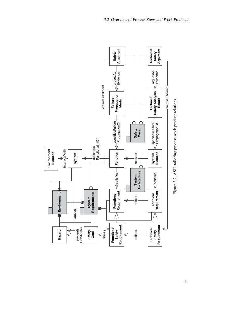
3.2 Overview of Process Steps and Work Products
Saf
ety
Cas
eS
yste
m
Arc
hit
ectu
re
Sys
tem
R
eq
uir
em
en
ts
En
viro
nm
ent
Fu
nct
ion
alS
afet
y R
eq
uir
em
en
t
Saf
ety
Go
al
Haz
ard
Fu
nc
tio
n
Sys
tem
Ele
me
nt
Tec
hn
ical
Saf
ety
Re
qu
ire
me
nt
Fa
ilure
Pro
pag
atio
nM
od
el
Saf
ety
Arg
um
en
t
Sys
tem
En
viro
nm
ent
Ele
me
nt
Fu
nct
ion
alR
eq
uir
em
en
t
Tec
hn
ical
Re
qu
ire
me
nt
Tec
hn
ical
Saf
ety
An
alys
is
Res
ult
Tec
hn
ical
Saf
ety
Arg
um
en
t
prevents
OrMitigates
causes
interactsWith
refines
refines
refines
satisfies
satisfies
realizes
describes
FunctionalityOf
specifiesFailure
PropagationOf
specifiesFailure
PropagationOf
arguesAs
Evidence
claimsFulfillment ar
guesAs
Evidence
claimsFulfillment
Figu
re3.
2:A
SIL
tailo
ring
proc
ess
wor
kpr
oduc
trel
atio
ns
41

3 ASIL Tailoring Process on Functional Safety Requirements
In Step 1 of the ASIL tailoring process, the CONSENS environment model for the SUDis specified and analyzed for hazards. The environment describes the interfaces between thesystem and its surrounding environment elements that it has to interact with (cf. Figure 3.2).In addition, we specify the hazards that could be caused by failures occurring on the outgoinginterfaces (ports) of the system and their safety goals. The hazards and their ASILs areidentified through a hazard analysis (cf. Definition 2.12 on page 19) on the system as ablack-box and its environment [Int11d]. Step 1 is described in detail in Section 3.3.
In Step 2.1, the CONSENS function hierarchy is developed. It describes a breakdownof the overall functionality of the SUD, represented by a root function, into sub-functionsuntil technical realizations can be found. Each function describes how a set of inputs isused to generate outputs to fulfill a sub-task of the overall system. Inputs and outputs arealso decomposed onto sub-functions. In Step 2.2, the functional requirements and functionalsafety requirements of each function are specified using a formal modeling language. We useModal Sequence Diagrams (MSDs) that are a formal, scenario-based requirements languagebased on UML sequence diagrams (cf. Section 2.7). Requirements specified in this languagecan automatically be processed to identify failure propagation paths. Step 2.1 and Step 2.2are described in further detail in Section 3.4.
To find possible ASIL tailoring solutions and to verify that an applied tailoring is valid,safety analyses have to be performed. Thus, in the automated Step 2.3, the safety managergenerates a failure propagation model to be used for safety analysis on the function hierarchy.We use Component Fault Trees (CFTs) that allow to specify decomposed fault trees forcomponent-oriented models like the CONSENS function hierarchy (cf. Section 2.4.2). Thefailure propagation model is generated from the structure of the function hierarchy and thebehavior described in the formal functional (safety) requirements. The failure propagationmodel is used to calculate valid, tailored ASIL values for the functions of the functionhierarchy in the automated Step 2.4. The work products of the ASIL tailoring process areconnected and traced to construct and maintain a safety argument in form of a model usingthe Goal Structuring Notation (GSN) as suggested by ISO 26262 [Int12b] (cf. Section 2.8).Step 2.3 and Step 2.4 are described in further detail in Section 3.5.
The steps 2.1 to 2.4 are iterated until the tailored ASILs of the functions meet the safetymanager’s expectations and the detail level of the functions is sufficiently trivial to berealized by technical system elements of the system architecture. In the final Step 3,the system architecture is defined by the system designer (as CONSENS active structure)and the functions are allocated to their realizing system elements. The functional (safety)requirements of the functions have to be refined into technical (safety) requirements thatare satisfied by the system elements (cf. Figure 3.2). Afterward, safety analysis has to berepeated on the technical level of the system architecture to show that the ASIL tailoringon functional level remains valid on the system level. The result accordingly has to bedocumented in a technical safety argument (cf. Figure 3.2). Step 3 is described in detailin Section 3.6.
42

3.3 Analyzing the Environment and Hazards
3.3 Analyzing the Environment and Hazards
In Step 1 of the ASIL tailoring process, the environment of the SUD is specified and used toidentify possible hazards and their criticality (i.e., ASIL). Figure 3.3 shows the sub-actionsof Step 1.
1. Analyze Environment and Hazards
1.2 Apply HARA
1.1 AnalyzeEnvironment
CustomerRequirements
Environmentwith Hazards
Figure 3.3: Process Step 1 - Analyze Environment and Hazards
Step 1.1 is an instantiation of the item definition phase of ISO 26262 (cf. phase 3-5 inFigure 2.6 on page 20). The requirements engineer uses the customer requirements to definethe boundary of the system under development (i.e., the item) and to identify the environmentelements that the system has to interact with.
Step 1.2 corresponds to the hazard analysis and risk assessment phase (HARA) ofISO 26262 (cf. phase 3-7 in Figure 2.6 on page 20). Here, the safety manager uses thecustomer requirements and the specified environment to identify hazards that could becaused by the system.
The customer requirements are the input for the whole development process andspecifically for the system requirements analysis phase (cf. Section 2.1). They have to besatisfied by so-called system requirements which are the output of the system requirementsanalysis phase. The system requirements contain different types of requirements (cf.Figure 3.2). For each hazard a top-level safety requirement called safety goal is defined.The safety goals are later on refined into functional safety requirements in Step 2.1.
Figure 3.4 shows the environment with hazards for the EBEAS as refinement of thesketch in Figure 1.3 on page 4. The system EBEAS receives information from theenvironment elements Electronic Stability Control, Vehicle2X Communication, and AdaptiveCruise Control. The information received from the latter is depicted in the informationflow specification AccEcu2EbeasEcu. The Adaptive Cruise Control notifies the EBEASif an obstacle or a vehicle was detected (obstacleDetected, frontVehicleDetected), andsends the time in milliseconds until the detected object will be reached (timeToObstacle,timegapToFrontVehicle).
The EBEAS sends information to the environment elements Electronic Stability Control,Vehicle2X Communication, and Active Front Steering. These output interfaces are thelocations where failures of the EBEAS can cause hazards.
The hazards are identified via HARA (cf. Section 2.2) in Step 1.2 and depicted in thebottom of Figure 3.4. A failure of the EBEAS could lead to a missing automatic hard brakingof the vehicle via the Electronic Stability Control that controls the brakes (cf. H1 Hard BrakingOmission). Similarly, a failure could lead to a missing automatic evasive steering via the
43
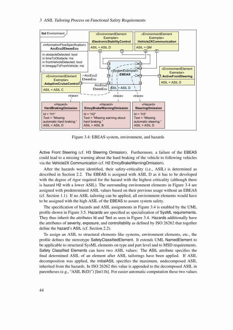
3 ASIL Tailoring Process on Functional Safety Requirements
ASIL = ASIL D
«SystemExemplar»:EBEAS
ASIL = ASIL D
«EnvironmentElementExemplar»
:ElectronicStabilityControl
ASIL = ASIL C
«EnvironmentElementExemplar»
:AdaptiveCruiseControl
ASIL = QM
«EnvironmentElementExemplar»
:Vehicle2XCommunication
ASIL = ASIL D
«EnvironmentElementExemplar»
:ActiveFrontSteering:~AccEcu2EbeasEcu
:AccEcu2EbeasEcu
Id = “H2“Text = “Missing warning about hard braking.“ASIL = ASIL B
«Hazard»EmcyBrakeWarningOmission
Id = “H3“Text = “Missing automatic steering.“ASIL = ASIL D
«Hazard»SteeringOmission
Id = “H1“Text = “Missing automatic hard braking.“ASIL = ASIL D
«Hazard»HardBrakingOmission
«trace» «trace» «trace»
ibd Environment
in obstacleDetected: boolin timeToObstacle: msin frontVehicleDetected: boolin timegapToFrontVehicle: ms...
«InformationFlowSpecification»AccEcu2EbeasEcu
Figure 3.4: EBEAS system, environment, and hazards
Active Front Steering (cf. H3 Steering Omission). Furthermore, a failure of the EBEAScould lead to a missing warning about the hard braking of the vehicle to following vehiclesvia the Vehicle2X Communication (cf. H2 EmcyBrakeWarningOmission).
After the hazards were identified, their safety-criticality (i.e., ASIL) is determined asdescribed in Section 2.2. The EBEAS is assigned with ASIL D as it has to be developedwith the degree of rigor required for the hazard with the highest criticality (although thereis hazard H2 with a lower ASIL). The surrounding environment elements in Figure 3.4 areassigned with predetermined ASIL values based on their previous usage without an EBEAS(cf. Section 1.1). If no ASIL tailoring can be applied, all environment elements would haveto be assigned with the high ASIL of the EBEAS to assure system safety.
The specification of hazards and ASIL assignments in Figure 3.4 is enabled by the UMLprofile shown in Figure 3.5. Hazards are specified as specialization of SysML requirements.They thus inherit the attributes Id and Text as seen in Figure 3.4. Hazards additionally havethe attributes of severity, exposure, and controllability as defined by ISO 26262 that togetherdefine the hazard’s ASIL (cf. Section 2.2).
To assign an ASIL to structural elements like systems, environment elements, etc., theprofile defines the stereotype SafetyClassifiedElement. It extends UML NamedElement tobe applicable to structural SysML elements on type and part level and to MSD requirements.Safety Classified Elements can have two ASIL values: The ASIL attribute specifies thefinal determined ASIL of an element after ASIL tailorings have been applied. If ASILdecomposition was applied, the initialASIL specifies the maximum, undecomposed ASILinherited from the hazards. In ISO 26262 this value is appended to the decomposed ASIL inparentheses (e.g., “ASIL B(D)”) [Int11h]. For easier automatic computation these two values
44

3.4 Specifying Functions and Requirements
«profile» Safety Profile
ASIL: ASILKindinitialASIL: ASILKind
«Stereotype»SafetyClassifiedElement
«Metaclass»NamedElement
TBDASIL_DASIL_CASIL_BASIL_AQM
«Enumeration»ASILKind
«Stereotype»SysML::
Requirement
severity: SeverityClassexposure: ExposureClasscontrollability: ControllabilityClassASIL: ASILKind
«Stereotype»Hazard
TBDS3S2S1S0
«Enumeration»SeverityClass
TBDE4E3E2E1E0
«Enumeration»ExposureClass
TBDC3C2C1C0
«Enumeration»ControllabilityClass
Figure 3.5: UML Profile for hazards and safety classified elements
are split in the profile. In the diagrams of this thesis, the parenthesis notation of ISO 26262 isappended to the ASIL attribute for better readability. The stereotype SafetyClassifiedElementis omitted in diagrams of this thesis for better readability, but the ASIL attribute is shown ina stereotype compartment or curly braces.
In addition, each attribute defined in the profile can be assigned a value of TBD (to bedetermined) to mark it as not yet fixed.
3.4 Specifying Functions and Requirements
In Steps 2.1 and 2.2 of the ASIL tailoring process, the function hierarchy and its (safety)requirements are developed. This section describes the process steps and the final workproducts produced in Steps 2.1 and 2.2. The detailed method how the work products arecreated is described in Chapter 4.
In Step 2.1, the function hierarchy is developed and refined. Figure 3.6 shows the sub-actions of Step 2.1. After the environment and hazards were specified in Step 1, the top-level function hierarchy is derived from the environment in Step 2.1.a). This action consistsof the specification of the root function of the function hierarchy representing the fullfunctionality of the SUD, and the functional abstraction of the SUD’s technical interfacesto the environment into input and output information. The top-level function hierarchy isafterward used as input for Step 2.2. In following iterations of the Steps 2.1 to 2.4, thefunction hierarchy is refined in Step 2.1.b). This refinement is the decomposition of thefunctionality of single functions (like the top-level root function) into smaller functions
45

3 ASIL Tailoring Process on Functional Safety Requirements
on the next level of the function hierarchy, including their input and output information.Furthermore, the structure of the function hierarchy can be revised based on the ASILtailoring results of Step 2.4.
2.1. Develop/Refine Function Hierarchy
Environment andHazards with ASILs
Function Hierarchywith Tailored ASILs
FunctionHierarchy
2.1.b) RefineFunction Hierarchy
2.1.a) DevelopTop-Level
Function Hierarchy
Figure 3.6: Process Step 2.1 - Develop/Refine Function Hierarchy
In Step 2.2, the functional (safety) requirements for the functions of the function hierarchyare developed and specified in form of MSDs (cf. Section 2.7). Figure 3.7 shows the sub-actions of Step 2.2. After the top-level function hierarchy was specified in Step 2.1.a), inStep 2.2.a) the according (safety) requirements for the top-level function are developed. Infollowing iterations, the top-level requirements are refined adhering to the refinement of thefunction hierarchy in Step 2.1.b).
2.2. Develop/Refine (Safety) Requirements
2.2.b) Refine(safety) MSDs
2.2.a) Develop(safety) MSDs
for top-level functionFunctionHierarchy
(Safety)MSDs
[no MSDsspecified yet]
[else]
Figure 3.7: Process Step 2.2 - Develop/Refine (Safety) Requirements for Functions
Figure 3.8 depicts an excerpt of the function hierarchy as result of Step 2.1. The figures 3.9and 3.10 show functional safety requirements (FSRs) for functions of the function hierarchyas result of Step 2.2.
The top-level function FEBEAS in Figure 3.8 represents the whole functionality of theSUD EBEAS. Thus, it also inherits its ASIL value ASIL D. Its ports represent the input andoutput information received from and sent to its environment (cf. Figure 3.4). For instance,the port p1 typed by the interface Acc2Ebeas represents the information received from theadaptive cruise control. The top-level function FEBEAS with its ports and interfaces isdeveloped in Step 2.1.a).
In Step 2.1.b), the top-level function FEBEAS is decomposed into the four functionsAnalyze Situation, Make Decision, Communicate With Other Vehicles, and Ensure
46

3.4 Specifying Functions and Requirements
reac
hin
gLas
tPoi
ntT
oBra
ke()
pass
edLa
stP
oint
ToB
rake
()pa
ssed
Last
Poi
ntT
oEva
de()
...
«int
erfa
ce»
Sit
uat
ion
alE
ven
ts
AS
IL =
AS
IL D
«Fun
ctio
n»
FE
BE
AS
«Fun
ctio
n»
An
alyz
eS
itu
ati
on
«Fun
ctio
n»
Co
mm
un
icat
eW
ith
Oth
erV
ehic
les
«Fun
ctio
n»
En
sure
Pas
sen
ger
Saf
ety
p2:V
2x2
Ebe
as
p1:
Acc
2E
beas
p3:~
Ebe
as2E
sc
p7:V
2x2
Ebe
as
p5:~
Situ
atio
nal
Eve
nts
«Fun
ctio
n»
Mak
eD
ecis
ion
p6:S
ituat
iona
lE
vent
sp4
:Acc
2Ebe
asp8
:~E
beas
2Esc
bd
d F
unct
ions
obst
acle
OrF
ront
Veh
icle
Det
ecte
d()
setT
imeg
apT
oFro
nt(t
imeg
ap:
ms)
...
«int
erfa
ce»
Acc
2Eb
eas
Figu
re3.
8:E
BE
AS
func
tion
hier
arch
y
47

3 ASIL Tailoring Process on Functional Safety Requirements
Passenger Safety. The purpose of the function Analyze Situation is to encapsulate therequirements for analyzing the current driving situation of the vehicle (e.g., distance tosurrounding vehicles and ego vehicle speed). The function Make Decision describesrequirements on making the decision to brake or evade based on the information providedby the functions Analyze Situation and Communicate With Other Vehicles. The latter’spurpose is to provide information received from other vehicles via Vehicle-to-Vehiclecommunication and to send information to those vehicles. The function Ensure PassengerSafety encapsulates requirements concerning the execution of the decision made by MakeDecision, i.e., activating the brakes or the evasive steering maneuver.
The information received/sent by the top-level function is decomposed among its sub-functions. It can be directly delegated to one function (like the port p1 to port p4) ordecomposed onto different functions with separate ports. The decomposed functions also canexchange additional information (like Situational Events between p5 and p6) that is requiredto fulfill the superordinate functionality.
Interfaces in the function hierarchy describe a high-level information exchange as anabstraction from technical details like sample time, resolution, etc. The interface Acc2Ebeasis a functional abstraction of the technical interface AccEcu2EbeasEcu in Figure 3.4. Forexample, it merges the technically separated messages for detection of obstacles and vehiclesinto one information. The interface SituationalEvents describes information sent from thefunction Analyze Situation to the function Make Decision. The information exchanged isabstracted to events like reaching or passing the last point to safely brake. Technically, thisinformation is complex to determine and consists of different sensor inputs in specific timeintervals.
The requirements for each function of the function hierarchy are specified as MSDs inStep 2.2. The following figures show some examples. The top MSD in Figure 3.9 specifies afunctional safety requirement FSR2.1 for the function Analyze Situation. If the time timegapuntil the leading vehicle would be hit is still long enough to safely brake (i.e., longer thantime4Braking) but shorter than that time plus a certain threshold brakeThreshold, then thefunction Analyze Situation shall inform the function Make Decision that the last point tosafely brake is about to be reached (cf. message reachingLastPointToBrake).
The bottom MSD in Figure 3.9 specifies a functional safety requirement FSR1.1 for thefunction Communicate With Other Vehicles. If the function receives information aboutan emergency brake warning from the vehicle in front, it shall inform the Make Decisionfunction.
The two MSDs in Figure 3.10 specify functional safety requirements for the functionMake Decision. The top MSD describes the requirement that if the Make Decision functionis informed about an emergency brake warning from the vehicle in front (cf. FSR1.1 inFigure 3.9), it shall decide to activate the emergency braking procedure of the functionEnsure Passenger Safety. Redundantly to this requirement, the bottom MSD in Figure 3.10describes the requirement that the Make Decision function shall make the same decision ifit is informed about reaching the last point to safely brake by the function Analyze Situation(cf. FSR2.1 in Figure 3.9).
The specification of the function hierarchy and the functional (safety) requirements asresulting from the Steps 2.1 and 2.2 is the input for the safety analysis on the functional(safety) requirements in the following Steps 2.3 and 2.4.
48

3.4 Specifying Functions and Requirements
as: AnalyzeSituation
md: MakeDecision
reachingLastPointToBrake
msd FSR2.1 Determine Time for Safe Braking
setTimegapToFront(timegap)
time4Braking< timegap <
time4Braking+brakeThreshold
cwov: CommunicateWith
OtherVehicles
md: MakeDecision
receivedEmcyBrakeWarningFromFront
msd FSR1.1 Pass Warnings from leading
receivedEmcyBrakeWarning
(c)
(h,e)
(h,e)
Figure 3.9: Requirements for functions Analyze Situation and Communicate With OtherVehicles
md:Make
Decision
cwov: Communicate
WithOtherVehicles
msd FSR1.2 Brake Decision on Warning
eps:Ensure
PassengerSafety
activateEmergencyBraking
receivedEmcyBrakeWarning
md:Make
Decision
msd FSR2.2 Brake Decision by Sensor
eps:Ensure
PassengerSafety
activateEmergencyBraking
as:AnalyzeSituation
reachingLastPointToBrake
(h,e)
(h,e)
Figure 3.10: Requirements for function Make Decision
49

3 ASIL Tailoring Process on Functional Safety Requirements
3.5 Safety Analysis and ASIL Allocation
In Steps 2.3 and 2.4 of the ASIL tailoring process, a safety analysis is performed on thefunction hierarchy to allocate tailored ASIL values to the functions. Together with the ASILallocation to functions, a safety argument is developed. This section describes the processsteps and the final work products produced in Steps 2.3 and 2.4. The detailed methods howthe work products are created are described in Chapters 5 and 6.
In Step 2.3, a failure propagation model in form of CFTs (cf. Section 2.4.2) is generatedfrom the function hierarchy and the functional (safety) requirements. Figure 3.11 shows thesub-actions of Step 2.3. Initially, the safety manager has to specify which output failuremodes of the top-level function lead to a certain hazard by a so-called Hazard CFT inStep 2.3.1. Afterward and in all following iterations, a failure propagation model in formof interleaved CFTs is automatically generated from the function hierarchy and its (safety)requirements in Step 2.3.2. These CFTs are generated from the hierarchical structure of thefunctions and the requirements specified as MSDs. In addition, they are connected to themanually specified Hazard CFTs. This enables safety analyses to find failure propagationpaths through the function hierarchy leading to a hazard.
2.3. Generate Failure Propagation Model
FunctionHierarchy
(Safety)MSDs
CFTs
2.3.2 GenerateCFTs
2.3.1 SpecifyHazard CFT
[no Hazard CFTspecified yet]
[else]
Figure 3.11: Process Step 2.3 - Generate Failure Propagation Model for Function Hierarchy
In Step 2.4, the failure propagation model is used to calculate valid ASIL tailorings andallocate ASILs to the functions of the function hierarchy. Figure 3.12 shows the automatedsub-actions of Step 2.4. First, in Step 2.4.1 the ASIL of each hazard in Hazard CFTs ispropagated along the failure propagation paths of the failure propagation model and allocatedto input/output failure modes of the different sub-CFTs. Where possible, the ASIL isdecomposed or reduced obeying the ASIL tailoring rules (cf. Section 2.5). As the CFTsmirror the structure of the function hierarchy, afterward in Step 2.4.2, the highest ASIL ofeach CFT is allocated to its corresponding function of the function hierarchy. Finally, inStep 2.4.3, the safety argument, in form of a GSN model (cf. Section 2.8), assuring thevalidity of applied ASIL tailorings in Step 2.4.1 is generated. This is done based on thecalculated ASIL propagation paths and ASIL allocation of the Steps 2.4.1 and 2.4.2.
50

3.5 Safety Analysis and ASIL Allocation
2.4. Calculate ASIL Allocation
CFTs
Function Hierarchy
Function Hierarchywith ASILs
2.4.1 CalculateASILs for
Failure Modes2.4.3 Generate
Safety Argument
2.4.2 AllocateASILs to
Functions
SafetyArgument
Figure 3.12: Process Step 2.4 - Calculate ASIL Allocation for Function Hierarchy
Figure 3.13 depicts the failure propagation model for the function hierarchy in form ofCFTs as result of Step 2.3. Figure 3.14 shows the function hierarchy with the resulting ASILallocation as result of Step 2.4.
In the failure propagation model, the hazard Hard Braking Omission from Figure 3.4is represented by the fault tree event :HardBrakingOmission inside the Hazard CFTHardBrakingOmissionCFT (cf. Figure 3.13). This Hazard CFT is the result of Step 2.3.1.The hazard is caused by an omission failure of the function FEBEAS represented by theCFT FEBEASCFT (automatically generated in Step 2.3.2). The omission failure propagatesthrough the function Ensure Passenger Safety (details omitted in Figure 3.13) and is causedby an omission failure of the information activateEmergencyBraking of the function MakeDecision.
The failure propagation of the CFT MakeDecisionCFT is automatically derived from therequirements in Figure 3.10. The information activateEmergencyBraking is not sent by thefunction Make Decision, if the function has an internal failure :Crash (e.g., because thesystem element realizing the function fails), or if the information reachingLastPointToBrakeand receivedEmcyBrakeWarning are both omitted.
The information reachingLastPointToBrake is sent by the function Analyze Situation.So, the omission failure reachingLastPointToBrake:O is propagating from its CFTAnalyzeSituationCFT. Similarly, the omission failure receivedEmcyBrakeWarning:O iscaused by the CFT CommunicateWithOtherVehiclesCFT.
The ASIL values annotated to failure modes, gates, and CFTs in Figure 3.13 resultfrom Step 2.4.1. The hazard Hard Braking Omission is an ASIL D hazard. So, ASIL Dpropagates along the failure propagation path of the according omission failure intoFEBEASCFT, through EnsurePassengerSafetyCFT, and into MakeDecisionCFT. After theAND gate the ASIL is decomposed, because both input failures reachingLastPointToBrake:Oand receivedEmcyBrakeWarning:O have to occur at the same time, in order for theinformation activateEmergencyBraking not to be sent by Make Decision. Accordingto the ASIL tailoring rules, the ASILs of the two CFTs AnalyzeSituationCFT andCommunicateWithOtherVehiclesCFT can be reduced to ASIL B(D) (cf. Section 2.5.2).
Figure 3.14 shows the function hierarchy from Figure 3.8 after Step 2.4.2. ASILs areallocated to the sub-functions as prescribed by the failure propagation model in Figure 3.13.The top-level function FEBEAS keeps the original ASIL D from the hazard Hard BrakingOmission. Ensure Passenger Safety and Make Decision remain ASIL D functions as
51

3 ASIL Tailoring Process on Functional Safety Requirements
«CFT» {ASIL = ASIL D}:FEBEASCFT
«CFT» {ASIL = ASIL D} :MakeDecisionCFT
o
:Crash
«OR»
oo
«AND»
«CFT» {ASIL = ASIL D}:EnsurePassengerSafetyCFT
...
«CFT»{ASIL = ASIL B(D)}
:AnalyzeSituationCFT...
«CFT»{ASIL = ASIL B(D)}
:CommunicateWithOtherVehiclesCFT
...
{ASIL =ASIL D}
{ASIL = ASIL D}
{ASIL =ASIL D}
o
o o
o
o
o
ooo
...
«HazardCFT»:HardBrakingOmissionCFT
«Event»:HardBraking
Omission
o
ibd Failure Propagation Model
{ASIL = ASIL D}activateEmergencyBraking:~O
{ASIL = ASIL B(D)}receivedEmcy
BrakeWarning:O
{ASIL = ASIL B(D)}reachingLast
PointToBrake:O
Figure 3.13: Failure propagation and ASIL allocation of function hierarchy (focused on MakeDecision)
52

3.5 Safety Analysis and ASIL Allocation
well. However, the ASILs of the functions Analyze Situation and Communicate With OtherVehicles could be reduced to ASIL B(D).
ASIL = ASIL D
«Function»FEBEAS
ASIL = ASIL B(D)
«Function»AnalyzeSituation
ASIL = ASIL B(D)
«Function»Communicate
WithOtherVehicles
ASIL = ASIL D
«Function»Ensure
PassengerSafety
ASIL = ASIL D
«Function»Make
Decision
bdd Functions
Figure 3.14: EBEAS function hierarchy with allocated ASILs
Based on the ASIL allocation to functions, a safety argument is automatically derived inStep 2.4.3. The safety argument for the calculated ASIL allocation is specified as GSN modelin Figure 3.15. The hazards H1 and H3 from Figure 3.4 are addressed by the safety goal SG1which is refined by functional safety requirements FSR1 and others. FSR1 is decomposedinto the requirements FSR1.2, FSR2.2, and the tailored requirements FSR1.1 and FSR2.1(cf. Figures 3.9 and 3.10).
FSR1.2 and FSR2.2 each make sure that the brake decision is made in the case of ahard braking of the leading vehicle. Thus, they are the reason for the AND gate in theCFT in Figure 3.13 that indicates a possibility of ASIL decomposition. This ASIL tailoringtechnique was applied on the requirements FSR1.1 and FSR2.1 that redundantly make surethat the information needed to make the brake decision is provided to the function MakeDecision (i.e., the requirement FSR1.2 or FSR2.2).
For valid ASIL decomposition upon the functions Analyze Situation and CommunicateWith Other Vehicles that the requirements FSR1.2 and FSR2.2 belong to, the functionshave to be independent (cf. Section 2.5.2). Thus, the three requirements FSR1.5, FSR1.6,and FSR1.7 for absence of cascading and common cause failures are added. That theserequirements are fulfilled is shown by the CFT FEBEASCFT in Figure 3.13: there is nofailure propagation path from one function’s CFT to the other and no common failure modeas input to both function CFTs.
By executing the automated steps 2.3 and 2.4, ASIL values are allocated to the functions ofthe function hierarchy and tailored where possible. The validity of applied ASIL tailoringsis assured by safety analysis on a failure propagation model and documented in a safetyargument. The applied ASIL tailoring can then be reviewed by the safety manager. He mightadapt and refine the function hierarchy and safety requirements to gain better ASIL tailoringresults in following iterations of the steps 2.1 to 2.4. Once the function hierarchy and itsASIL allocation are considered final, the functions have to be allocated to system elementsof the system architecture that realize their functionality in Step 3.
53

3 ASIL Tailoring Process on Functional Safety Requirements
«SupportedBy»
req Safety Argument
Text = “In EmcyBrake situation, activate braking or evading“ASIL = ASIL D
«Goal»SG1
«Context»Hazard H1
ASIL = ASIL D
«Solution»FEBEASCFT
«Strategy»ASIL Decomposition
Text = “Argument oversufficient independence“
Text = “Brake on Warning“ASIL = ASIL D
«Goal»FSR1
Text = “...“ASIL = ...
«Goal»FSR...
«SupportedBy»
«InContextOf»
«SupportedBy»
Text = “Brake Decision on Warning“ASIL = ASIL D
«Goal»FSR1.2
Text = “Brake Decision by Sensor“ASIL = ASIL D
«Goal»FSR2.2
Text = “Execute Brake Decision“ASIL = ASIL D
«Goal»FSR1.3
Text = “Pass Warnings from leading“ASIL = ASIL B(D)
«Goal»FSR1.1
Text = “Determine Time 4 Safe Braking“ASIL = ASIL B(D)
«Goal»FSR2.1
Text = “No cascading failures from AnalyzeSituation to CommunicateWithOtherVehicles“ASIL = ASIL D
«Goal»FSR1.5
Text = “No cascading failures from CommunicateWithOtherVehicles to AnalyzeSituation“ASIL = ASIL D
«Goal»FSR1.6
Text = “No common cause failures of AnalyzeSituation and CommunicateWithOtherVehicles“ASIL = ASIL D
«Goal»FSR1.7
«SupportedBy»«SupportedBy»
«SupportedBy»
«SupportedBy»
«SupportedBy»
«SupportedBy»
«SupportedBy»«SupportedBy»
«SupportedBy»
«SupportedBy»
«Context»Hazard H3
ASIL = ASIL D
«InContextOf»
«SupportedBy»
Text = “FSR1.1 and FSR2.1 are redundant“ASIL = ASIL D
«Goal»TG1
«SupportedBy»
Figure 3.15: Safety argument for ASIL allocation
54

3.6 Allocating Functions to System Architecture
3.6 Allocating Functions to System Architecture
In Step 3 of the ASIL tailoring process, the functions of the function hierarchy are allocatedto parts of the system architecture that realize them technically. In addition, the applied ASILtailoring on the functional level is checked for validity on the technical level after allocation.Figure 3.16 shows the sub-actions of Step 3.
3. Define System Architecture and AllocateFunctions
3.2 Allocate Functionsto System Elements
3.1 DefineActive StructureFunction
HierarchyActiveStructure
3.3 ValidateASIL Allocation
Figure 3.16: Process Step 3 - Define System Architecture and Allocate Functions to SystemElements
In Step 3.1, the system designer defines the system architecture in form of a CONSENSactive structure (cf. Section 2.6) based on the function hierarchy. This step is following theCONSENS systems engineering method.
In Step 3.2, the system designer links the system elements of the system architecture tothe functions of the function hierarchy whose functionality (i.e., functional requirements)they realize to maintain traceability from requirements to realization [FHM12]. The systemelements inherit the highest ASIL value of the functions they realize. In conjunction,the safety manager refines the functional safety requirements addressing the functions intotechnical safety requirements addressing the system elements.
In Step 3.3, the safety manager performs a safety analysis similar to that on the functionhierarchy (cf. Section 3.5) on the system architecture to validate that the inherited ASILvalues of the system elements are valid and independence claims hold. A safety analysis onCONSENS active structures is presented by Gausemeier et al. [GPD+09].
Figure 3.17 shows the system architecture of the EBEAS and the allocated functions ofthe function hierarchy from Figure 3.14. The interior of the EBEAS is defined in Step 3.1 bythe system designer and allocated to the realized functions in Step 3.2. The ASIL B(D)functionality of the function Communicate With Other Vehicles is realized by softwareon the core :PerformanceCore and a bus interface :V2XBusInterface to the Vehicle2XCommunication. The highly safety-critical ASIL D functionality of the functions MakeDecision and Ensure Passenger Safety is realized on separated cores running in lockstepmode (:LockstepCores). The function Ensure Passenger Safety requires communicationwith actuator ECUs and thus is also partly realized by the separated redundant bus interfaces:ADASBusInterfaces. Safety analysis has shown that the function Analyze Situation can bedeveloped ASIL B(D). However, it requires communication with the functionality providedby the Adaptive Cruise Control that is connected to the same bus as the more critical ECUs.Thus, the function is realized by the :ADASBusInterfaces and :LockstepCore as well. This
55
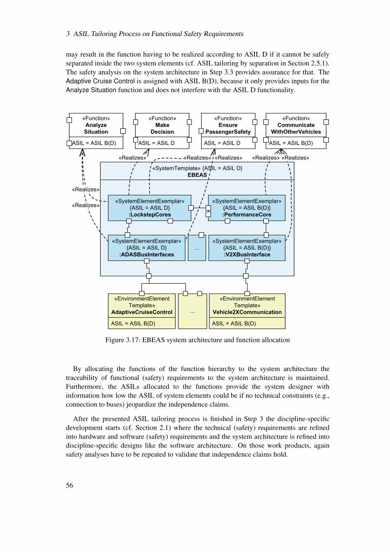
3 ASIL Tailoring Process on Functional Safety Requirements
may result in the function having to be realized according to ASIL D if it cannot be safelyseparated inside the two system elements (cf. ASIL tailoring by separation in Section 2.5.1).The safety analysis on the system architecture in Step 3.3 provides assurance for that. TheAdaptive Cruise Control is assigned with ASIL B(D), because it only provides inputs for theAnalyze Situation function and does not interfere with the ASIL D functionality.
«SystemTemplate» {ASIL = ASIL D}EBEAS
«SystemElementExemplar»{ASIL = ASIL D}:LockstepCores
...«SystemElementExemplar»
{ASIL = ASIL B(D)}:V2XBusInterface
«SystemElementExemplar»{ASIL = ASIL B(D)}:PerformanceCore
«SystemElementExemplar»{ASIL = ASIL D}
:ADASBusInterfaces
«Realizes» «Realizes»
«Realizes»
«Realizes»
ASIL = ASIL D
«Function»Ensure
PassengerSafety
ASIL = ASIL B(D)
«Function»AnalyzeSituation
ASIL = ASIL B(D)
«Function»Communicate
WithOtherVehicles
«Realizes»
ASIL = ASIL D
«Function»Make
Decision
«Realizes»
ASIL = ASIL B(D)
«EnvironmentElementTemplate»
AdaptiveCruiseControl
ASIL = ASIL B(D)
«EnvironmentElementTemplate»
Vehicle2XCommunication...
«Realizes»
Figure 3.17: EBEAS system architecture and function allocation
By allocating the functions of the function hierarchy to the system architecture thetraceability of functional (safety) requirements to the system architecture is maintained.Furthermore, the ASILs allocated to the functions provide the system designer withinformation how low the ASIL of system elements could be if no technical constraints (e.g.,connection to buses) jeopardize the independence claims.
After the presented ASIL tailoring process is finished in Step 3 the discipline-specificdevelopment starts (cf. Section 2.1) where the technical (safety) requirements are refinedinto hardware and software (safety) requirements and the system architecture is refined intodiscipline-specific designs like the software architecture. On those work products, againsafety analyses have to be repeated to validate that independence claims hold.
56

3.7 Assumptions & Limitations
3.7 Assumptions & Limitations
The safety-criticality tailoring process presented in this chapter is applied to the automotivedomain. It uses the terminology of automotive-specific standards and is embedded into anautomotive-specific development process. However, safety-criticality levels like the ASILalso exist in other mechatronic systems domains (cf. Section 2.3). These domains havesafety standards similar to ISO 26262 with comparable concepts and terminology. In fact,many of these standards are based on the same base standard IEC 61508 [Int10a]. The usedautomotive-specific development process is compliant to Automotive SPICE [Aut10] whichis a specialization of the general software process maturity model SPICE [Int12a]. Thus, weassume that the presented tailoring process is also applicable to other mechatronic systemsdomains.
The tailoring process is embedded in a development process following the V modelcompliant to Automotive SPICE (cf. Section 2.1). An embedding into agile developmentprocesses like SCRUM [Sch97] has not been considered. However, there exists workdiscussing the applicability of SPICE to agile processes [LF09]. So, the migration to agileshould be possible.
The automotive safety standard ISO 26262 has to be obeyed in the developmentof embedded systems consisting of software and hardware (electrics/electronics). Thedevelopment of mechanics is not considered. Consequently, the ASIL tailoring process islimited to tailoring among functions that are realized by software or hardware.
ISO 26262 specifies requirements for the development of a so-called Safety Element out ofContext (SEooC). “An SEooC is a safety-related element which is not developed for a specificitem. This means it is not developed in the context of a particular vehicle” [Int12b]. A typicalexample of an SEooC is a platform project of a supplier that develops a system that shall bedelivered to different customers with only slight changes to its interfaces. For such a systemthe concrete environment is not known initially. Thus, assumptions about the environmentand specifically the hazards, failure propagation, and allocated ASIL values have to be made.In the presented process we assume that the environment of systems interacting with the SUDis known. We did not take SEooC development into account.
3.8 Related Work
Existing approaches for ASIL tailoring are applied in the phases of system architecturaldesign or software design [APW+14; APW+13; PLB+10][MAL+12]. They calculate anASIL allocation to subsystems of a technical architecture with known failure propagation andsafety mechanisms already in place. They assume that ASIL tailoring measures (separationand decomposition) have already been applied – both on requirements and architectural level.Moreover, they do not consider the documentation of a corresponding safety argument.
Based on the EAST-ADL [EAS13] a safety engineering process has been defined[SCL+10]. It distinguishes a functional and technical level but does not integrate an ASILtailoring process on functional safety requirements.
Beckers et al. present a process for derivation of functional safety requirements [BCF+14].They specify textual requirements in UML class attributes using a UML profile (notextending SysML). They do not use a function hierarchy. The functional safety requirements
57

3 ASIL Tailoring Process on Functional Safety Requirements
are arbitrarily structured and directly connected to safety goals. ASIL decomposition is partof their process but as a completely manual step.
In summary, the existing approaches do not provide a process for ASIL tailoring inthe requirements analysis phase. They rather apply ASIL calculation and allocation onsystem and software architectures based on the manually specified failure propagation ofsubsystems. In addition, the approaches do not consider the documentation of safetyarguments for applied ASIL tailorings.
3.9 Conclusion
This chapter introduces the ASIL tailoring process working on functional safetyrequirements. Figure 3.18 gives an overview of the EBEAS example work products intheir final state after the process was executed. The first step of the process is to specifythe system’s environment, identify hazards that the system can cause and determine theirASIL values. In Figure 3.18, the top-left diagram Environment sketches the environment andhazards of the EBEAS. There is an ASIL D hazard H1 named Hard Braking Omission that istraced to an outgoing port of the SUD.
Afterward, safety requirements are derived for the functions that the system shall realize.The Function Hierarchy diagram in Figure 3.18 shows the break down of the overallfunctionality FEBEAS of the SUD into sub-functions like Make Decision. The diagramFSR1.2 Brake Decision on Warning shows an example of a safety requirement for thefunction Make Decision. If it receives the information of an emergency brake warningreceivedEmcyBrakeWarning, it shall decide to activate Emergency Braking.
Based on the structure of the function hierarchy and their requirements (especiallyfunctional safety requirements), an automated safety analysis is performed to allocate tailoredASIL values to the functions. The Failure Propagation Model diagram in Figure 3.18describes which failures propagating through the function hierarchy lead to the Hard BrakingOmission hazard. The CFT Make Decision CFT in the middle of the diagram describes thefailure propagation through the function Make Decision. It shows that the function has toCrash or two input failures have to occur at the same time (cf. the AND gate) in order foran output failure to lead to the hazard. The AND gate in the CFT Make Decision CFT ofFigure 3.18 indicates a possibility for ASIL tailoring. Only if its two ingoing failures occursimultaneously, an outgoing failure will propagate on to the OR gate. The analysis of thefailure propagation model provides assurance that the ASIL D propagating from the hazardHard Braking Omission can be decomposed into the two ASIL B(D) input failures of MakeDecision CFT. Thus, the two connected CFTs and their corresponding functions inherit thatlower ASIL.
The validity of applied ASIL tailorings is automatically documented in form of a model-based safety argument in a safety case. The Safety Argument diagram in Figure 3.18documents an argument for the validity of the applied ASIL tailoring. It connects the hazardH1, the refined and decomposed safety requirements (i.e., MSDs), and the evidence for safetyrequirement fulfillment in form of CFTs.
The function hierarchy and the functional safety requirements are refined by iteration andfinally allocated to the technical system architecture. In the example System Architecturediagram of Figure 3.18 the EBEAS is comprised of four system elements. They are
58

3.9 Conclusion
req
Sa
fety
Arg
um
ent
Tex
t = “
...“
AS
IL =
AS
IL D
«Goa
l»S
G1
«Con
text
»H
azar
d H
1
AS
IL =
AS
IL D
«Sol
utio
n»F
EB
EA
SC
FT
AS
IL =
AS
IL D
«Goa
l»F
SR
1
AS
IL =
...
«Goa
l»F
SR
...
AS
IL =
AS
IL D
«Goa
l»F
SR
1.2
AS
IL =
AS
IL B
(D)
«Goa
l»F
SR
1.1
AS
IL =
AS
IL B
(D)
«Goa
l»F
SR
2.1
Tex
t = “
No
CF
...“
AS
IL =
AS
IL D
«Goa
l»F
SR
...
«Str
ateg
y»A
SIL
Dec
ompo
sitio
n
Tex
t = “
FS
R1.
1 &
2.1
...“
AS
IL =
AS
IL D
«Goa
l»T
G1
AS
IL =
AS
IL D
«Goa
l»F
SR
...
ibd
Sys
tem
Arc
hite
ctur
e
AS
IL =
AS
IL D
«S
yste
m»
EB
EA
S
«S
yste
mE
lem
ent»
{AS
IL =
AS
IL D
}:.
..
«S
yste
mE
lem
ent»
{AS
IL =
AS
IL B
(D)}
:...
«S
yste
mE
lem
ent»
{AS
IL =
AS
IL B
(D)}
:...
«S
yste
mE
lem
ent»
{AS
IL =
AS
IL D
}:.
..
«R
ea
lizes
»
«R
ea
lizes
»
«R
ea
lizes
»
AS
IL =
AS
IL D
«F
un
ctio
n»
...
AS
IL =
AS
IL B
(D)
«F
un
ctio
n»
...
AS
IL =
AS
IL B
(D)
«Fu
nct
ion
»..
.
«R
ea
lizes
»
AS
IL =
AS
IL D
«F
un
ctio
n»
Mak
eD
ec
isio
n
«R
ea
lizes
»
AS
IL =
AS
IL B
(D)
«En
viro
nm
en
tEle
me
nt»
Ad
apti
veC
ruis
eC
on
tro
l
AS
IL =
AS
IL B
(D)
«E
nvi
ron
me
ntE
lem
en
t»V
ehic
le2X
Co
mm
un
icat
ion
...
«R
ea
lizes
»
AS
IL =
AS
IL D
«Fu
nct
ion
»F
EB
EA
S
«
CF
T»
{AS
IL =
AS
IL D
}:F
EB
EA
SC
FT
«
CF
T»
{AS
IL =
AS
IL D
}
:Mak
eDec
isio
nC
FT
o
:Cra
sh
«OR
»
oo
«AN
D»
«CF
T»
{AS
IL =
AS
IL D
}:.
..
«CF
T»
{AS
IL =
AS
IL B
(D)}
:...
«CF
T»
{AS
IL =
AS
IL B
(D)}
:...
o
oo
o
o
o
oo
o
{AS
IL =
AS
IL D
}a
ctiv
ate
Em
erg
en
cyB
raki
ng
:~O
md:
Mak
eD
eci
sion
...
ms
d F
SR
1.2
Bra
ke D
eci
sion
on
Wa
rnin
g
...
act
iva
teE
mer
ge
ncy
Bra
kin
g
rece
ive
dE
mcy
Bra
keW
arn
ing
«Sys
tem
»{A
SIL
= A
SIL
D}
:EB
EA
S
:...
«E
nvi
ron
me
ntE
lem
ent
»:A
dap
tive
Cru
iseC
on
tro
l
«E
nvi
ron
me
ntE
lem
ent
»:V
ehic
le2X
Co
mm
un
icat
ion
«H
aza
rd»
...
Id =
“H
1“T
ext
= ..
.A
SIL
= A
SIL
D
«H
aza
rd»
Har
dB
rak
ing
Om
issi
on
«tr
ace
»
«tr
ace
»
ibd
En
viro
nm
en
t
bd
d F
unc
tion
Hie
rarc
hy
ibd
Fa
ilure
Pro
pa
ga
tion
Mo
de
l
ms
d F
SR
...m
sd
FS
R...
«Haz
ardC
FT
»:H
ard
Bra
kin
gO
mis
sio
nC
FT
«E
ven
t»:H
ardB
raki
ngO
mis
sion
o«
trac
e»
«tr
ace
»
«tr
ace
»
{AS
IL =
AS
IL B
(D)}
...:O
{AS
IL =
AS
IL B
(D)}
rece
ive
dE
mcy
Bra
keW
arn
ing
:O
Figu
re3.
18:S
ketc
hof
ASI
Lta
ilori
ngpr
oces
sw
ork
prod
ucts
59

3 ASIL Tailoring Process on Functional Safety Requirements
connected to the functions that they realize and inherit the highest ASIL of the realizedfunctions.
This systematic ASIL tailoring process allows to plan safety measures and required effortearly in the development process (i.e. during system requirements analysis). Furthermore, itsautomated steps remove error-prone and time-consuming manual tasks of the safety manager.This fosters the application of ASIL tailoring already during requirements analysis which isrequired due to the increasing complexity of mixed-criticality systems.
In the following Chapter 4, the method for specifying the function hierarchy andcorresponding functional safety requirements is described in detail. Chapter 5 contains thedetails of the automated safety analysis and ASIL allocation on the function hierarchy. InChapter 6 the automatic documentation of safety arguments is elaborated.
60

4
SPECIFYING FORMAL FUNCTIONALSAFETY REQUIREMENTS
In Steps 2.1 and 2.2 of the ASIL tailoring process (cf. Figure 4.1), the function hierarchyand its (safety) requirements are developed and refined. This chapter describes the details ofthese process steps and the used methods.
act ASIL Tailoring Process
Sys
tem
Des
igne
r,
Saf
ety
Man
ager
1. Analyze Environment and Hazards
2.3. GenerateFailure Propagation Model
for Function Hierarchy
2.4. CalculateASIL Allocation forFunction Hierarchy
2.2. Develop/Refine(Safety) Requirements
for Functions
3. Define System Architecture andAllocate Functions to System Elements
2.1. Develop/RefineFunction Hierarchy
CustomerRequirements
«datastore»System Architecture
Req
uire
men
ts E
ngin
eer,
Saf
ety
Man
ager
[functions sufficiently trivial and ASIL allocation reasonable]
«datastore»System
Requirements
FunctionHierarchy
FunctionHierarchy
FunctionHierarchy
Functional (Safety)Requirements
FSRs
Environment and Hazards with ASILs
System Elementswith ASILs
FailurePropagation
Model
FPM«datastore»Safety Case
Environment and Hazards with ASILsor Function Hierarchy [ASILs Tailored]
FunctionHierarchy
FunctionHierarchy
[ASILs Tailored]
Function Hierarchy[ASILs Tailored]
SafetyArgument
[else]
Figure 4.1: ASIL tailoring process with highlighted contents of Chapter 4
61
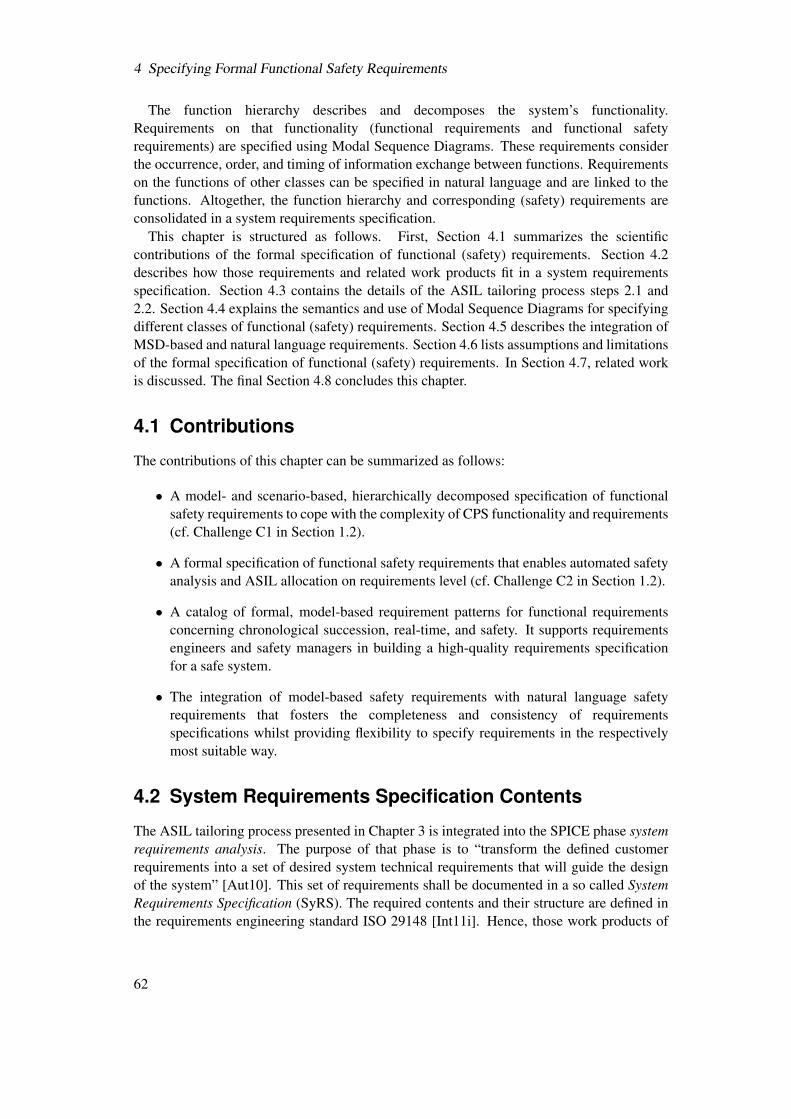
4 Specifying Formal Functional Safety Requirements
The function hierarchy describes and decomposes the system’s functionality.Requirements on that functionality (functional requirements and functional safetyrequirements) are specified using Modal Sequence Diagrams. These requirements considerthe occurrence, order, and timing of information exchange between functions. Requirementson the functions of other classes can be specified in natural language and are linked to thefunctions. Altogether, the function hierarchy and corresponding (safety) requirements areconsolidated in a system requirements specification.
This chapter is structured as follows. First, Section 4.1 summarizes the scientificcontributions of the formal specification of functional (safety) requirements. Section 4.2describes how those requirements and related work products fit in a system requirementsspecification. Section 4.3 contains the details of the ASIL tailoring process steps 2.1 and2.2. Section 4.4 explains the semantics and use of Modal Sequence Diagrams for specifyingdifferent classes of functional (safety) requirements. Section 4.5 describes the integration ofMSD-based and natural language requirements. Section 4.6 lists assumptions and limitationsof the formal specification of functional (safety) requirements. In Section 4.7, related workis discussed. The final Section 4.8 concludes this chapter.
4.1 Contributions
The contributions of this chapter can be summarized as follows:
• A model- and scenario-based, hierarchically decomposed specification of functionalsafety requirements to cope with the complexity of CPS functionality and requirements(cf. Challenge C1 in Section 1.2).
• A formal specification of functional safety requirements that enables automated safetyanalysis and ASIL allocation on requirements level (cf. Challenge C2 in Section 1.2).
• A catalog of formal, model-based requirement patterns for functional requirementsconcerning chronological succession, real-time, and safety. It supports requirementsengineers and safety managers in building a high-quality requirements specificationfor a safe system.
• The integration of model-based safety requirements with natural language safetyrequirements that fosters the completeness and consistency of requirementsspecifications whilst providing flexibility to specify requirements in the respectivelymost suitable way.
4.2 System Requirements Specification Contents
The ASIL tailoring process presented in Chapter 3 is integrated into the SPICE phase systemrequirements analysis. The purpose of that phase is to “transform the defined customerrequirements into a set of desired system technical requirements that will guide the designof the system” [Aut10]. This set of requirements shall be documented in a so called SystemRequirements Specification (SyRS). The required contents and their structure are defined inthe requirements engineering standard ISO 29148 [Int11i]. Hence, those work products of
62

4.2 System Requirements Specification Contents
the ASIL tailoring process that we consider part of the system requirements have to adhereto this standard as well. Figure 4.2 shows how the requirements work products used in theASIL tailoring process are structured in accordance with ISO 29148 and ISO 26262.
System Requirements
Environment
FunctionalSafety
Requirement
Safety Goal
Hazard
Function
TechnicalSafety
Requirement
SystemEnvironment
Element
FunctionalRequirement
TechnicalRequirement
preventsOrMitigates
causesinteracts
With
refines
refines refines
satisfies
Function Hierarchy
TechnicalRequirements
describesFunctionalityOf
Figure 4.2: Contents of the System Requirements Specification
ISO 29148 describes a so-called system context that shall contain “the major elements ofthe system [...] and how they interact [...], defining all significant interfaces crossing thesystem’s boundaries” [Int11i]. The environment specified in Step 1 of the ASIL tailoringprocess (cf. Section 3.3) specifies the system’s boundary, its technical interfaces, andsurrounding environment elements that it has to interact with (cf. Section 2.6). Thus, theEnviroment fits as system context.
ISO 26262 distinguishes between requirements on different abstraction levels (cf.Section 2.2). We consider safety goals, functional safety requirements and technical safetyrequirements as part of the SyRS. Safety goals are top-level safety requirements specifiedfor each identified hazard that lead to the functional safety requirements [Int11d]. Hazardsare caused by failures on the boundary of the system. Thus, we document safety goals andhazards together with the environment.
63

4 Specifying Formal Functional Safety Requirements
ISO 29148 defines so-called system functions that shall describe “major systemcapabilities, conditions, and constraints” [Int11i]. We specify system capabilities as functionsin the function hierarchy.
ISO 29148 prescribes no dedicated section for safety requirements, and ISO 26262 statesthat safety requirements can be documented together with other requirements if they are“unambiguously identifiable as safety requirements” (e.g., by an ASIL attribute) [Int11g].Thus, we document safety requirements as part of the SyRS together with other requirements.
We specify functional safety requirements together with other functional requirements asMSDs structured by the functions of the function hierarchy. This matches the organizationalapproach for requirements structuring functional hierarchy suggested by ISO 29148 [Int11i].
Technical safety requirements shall be allocated to elements of the system architecture[Int11e]. We document technical safety requirements together with other technicalrequirements textually, and group them in a system requirements section (that we callTechnical Requirements in Figure 4.2) as suggested by ISO 29148.
4.3 Systematic Development and Refinement of FunctionalSafety Requirements
This section describes the details about the substeps of the Steps 2.1 and 2.2 of the ASILtailoring process. In Step 2.1, the function hierarchy is developed and refined. Figure 4.3shows the sub-actions of Step 2.1. In Step 2.2, the functional (safety) requirements forthe functions of the function hierarchy are developed and specified in form of ModalSequence Diagrams (cf. Section 2.7). Figure 4.4 shows the sub-actions of Step 2.2. Afterthe environment and hazards were specified in Step 1, the top-level function hierarchy isderived from the environment in Step 2.1.a). This action consists of the specification ofthe root function of the function hierarchy representing the full functionality of the SUD,and the functional abstraction of the SUD’s technical interfaces to the environment intoinput and output information. The top-level function hierarchy is afterward used as inputfor Step 2.2.a). In Step 2.2.a), the according (safety) requirements for the top-level functionare developed. In following iterations of the process steps, the function hierarchy is refined inStep 2.1.b). This refinement is the decomposition of the functionality of single functions (likethe top-level root function) into smaller functions on the next level of the function hierarchy,including their input and output information. Furthermore, the structure of the functionhierarchy can be revised based on the ASIL tailoring results of Step 2.4 (cf. Chapter 5).Afterward, in Step 2.2.b), the functional (safety) requirements are refined adhering to therefinement of the function hierarchy.
Section 4.3.1 explains the systematic derivation of the top-level function hierarchyfrom the environment (Step 2.1.a)). Section 4.3.2 describes the specification of (safety)requirements on the function hierarchy using MSDs (Step 2.2.a)). Section 4.3.3 details therefinement steps for the function hierarchy and requirements (Steps 2.1.b) and 2.2.b)).
4.3.1 Deriving the Top-Level Function Hierarchy from the Environment
The CONSENS environment model specifies the system’s boundary, its technical interfaces,and surrounding elements that it has to interact with (cf. Section 2.6). The system is
64

4.3 Systematic Development and Refinement of Functional Safety Requirements
2.1. Develop/Refine Function Hierarchy
Environment andHazards with ASILs
Function Hierarchywith Tailored ASILs
FunctionHierarchy
2.1.b) RefineFunction Hierarchy
2.1.a) DevelopTop-Level
Function Hierarchy
Figure 4.3: Process Step 2.1 - Develop/Refine Function Hierarchy
2.2. Develop/Refine (Safety) Requirements
2.2.b) Refine(safety) MSDs
2.2.a) Develop(safety) MSDs
for top-level functionFunctionHierarchy
(Safety)MSDs
[no MSDsspecified yet]
[else]
Figure 4.4: Process Step 2.2 - Develop/Refine (Safety) Requirements for Functions
considered as a black box. Its internals are specified during the system architectural designphase in the system architecture. To come up with an adequate system architecture thatfulfills all requirements, we use a function hierarchy as an intermediate step. It is a means tocope with complexity by decomposing the required functionality that has to be realized bythe system and its architecture.
Figure 4.5 shows the detailed environment of the EBEAS (refinement of Figure 3.4 onpage 44) as result of ASIL Tailoring Process Step 1 (cf. Section 3.3). The internal blockdiagram in the bottom shows the system and its connections to the environment elements viaports typed by the interfaces shown in the block definition diagram in the top.
The Vehicle2X Communication sends and receives messages to and from other vehiclessurrounding the ego vehicle. Information that is relevant for the EBEAS is passed onto it (e.g., an emergency brake warning from a vehicle in front). In addition, theEBEAS commands the Vehicle2X Communication to send messages to certain vehicles (e.g.,emergency brake or evade requests and warnings). The Adaptive Cruise Control informs theEBEAS about detected obstacles and vehicles in front, and continuously provides informationabout the time it takes to reach those. The Electronic Stability Control continuously providesthe EBEAS with information about the current ego vehicle velocity and the maximal possibledeceleration (cf. maxDecel of interface EscEcu2EbeasEcu in Figure 4.5). The ElectronicStability Control controls the vehicle’s brakes. Hence, in case the EBEAS decides to executeemergency braking, it commands the Electronic Stability Control to perform a hard braking.The Active Front Steering can control the steering column. So, in case the EBEAS decides to
65
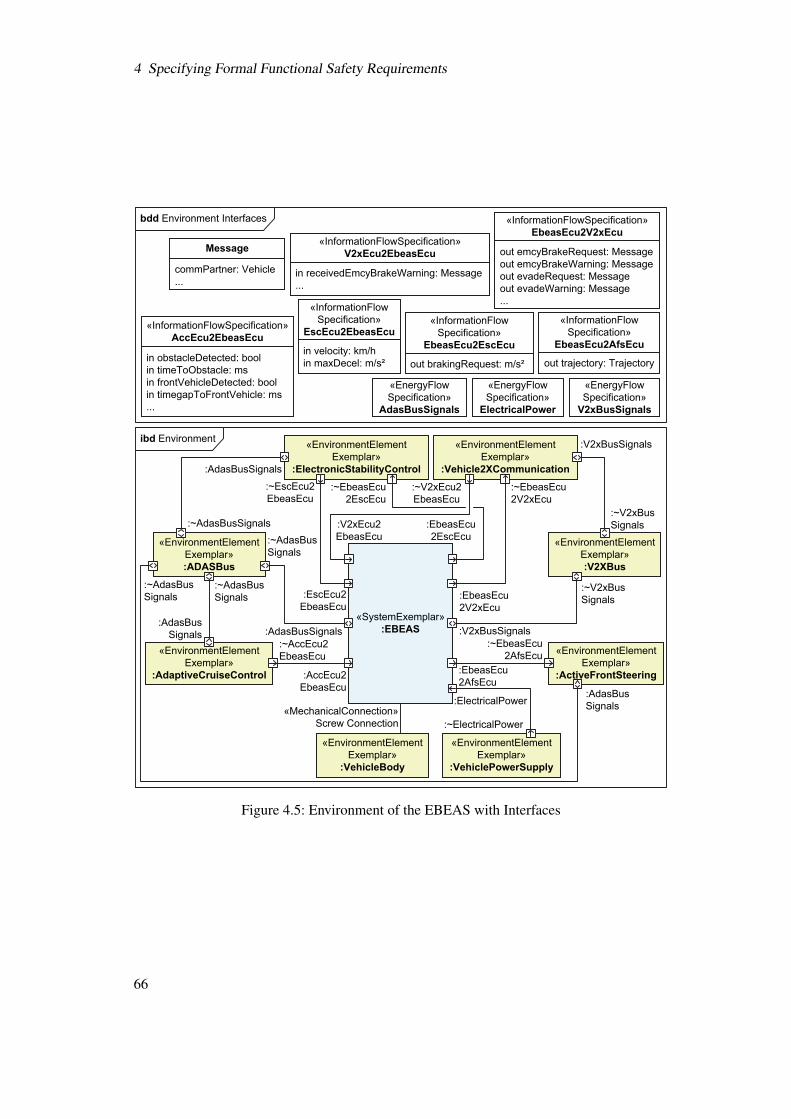
4 Specifying Formal Functional Safety Requirements
«SystemExemplar»:EBEAS
«EnvironmentElementExemplar»
:ElectronicStabilityControl
«EnvironmentElementExemplar»
:AdaptiveCruiseControl
«EnvironmentElementExemplar»
:Vehicle2XCommunication
«EnvironmentElementExemplar»
:ActiveFrontSteering
:~AccEcu2EbeasEcu
:~EscEcu2EbeasEcu
:~EbeasEcu2EscEcu
:~V2xEcu2EbeasEcu
:~EbeasEcu2V2xEcu
:~EbeasEcu2AfsEcu
:AccEcu2EbeasEcu
:EscEcu2EbeasEcu
:V2xEcu2EbeasEcu
:EbeasEcu2AfsEcu
:EbeasEcu2V2xEcu
:EbeasEcu2EscEcu
in obstacleDetected: boolin timeToObstacle: msin frontVehicleDetected: boolin timegapToFrontVehicle: ms...
«InformationFlowSpecification»AccEcu2EbeasEcu
«EnvironmentElementExemplar»:ADASBus
«EnvironmentElementExemplar»:V2XBus
:AdasBusSignals
:~AdasBusSignals
:~AdasBusSignals
:~AdasBusSignals
:~AdasBusSignals
:AdasBusSignals
:~V2xBusSignals
:~V2xBusSignals
:V2xBusSignals
:V2xBusSignals
:AdasBusSignals
:AdasBusSignals
bdd Environment Interfaces
ibd Environment
«EnergyFlowSpecification»
AdasBusSignals
«EnergyFlowSpecification»
V2xBusSignals
out emcyBrakeRequest: Messageout emcyBrakeWarning: Messageout evadeRequest: Messageout evadeWarning: Message...
«InformationFlowSpecification»EbeasEcu2V2xEcu
out brakingRequest: m/s²
«InformationFlowSpecification»
EbeasEcu2EscEcuin velocity: km/hin maxDecel: m/s²
«InformationFlowSpecification»
EscEcu2EbeasEcu
in receivedEmcyBrakeWarning: Message...
«InformationFlowSpecification»V2xEcu2EbeasEcu
out trajectory: Trajectory
«InformationFlowSpecification»
EbeasEcu2AfsEcu
«EnvironmentElementExemplar»
:VehicleBody
«EnvironmentElementExemplar»
:VehiclePowerSupply
:ElectricalPower
:~ElectricalPower«MechanicalConnection»
Screw Connection
«EnergyFlowSpecification»
ElectricalPower
commPartner: Vehicle...
Message
Figure 4.5: Environment of the EBEAS with Interfaces
66

4.3 Systematic Development and Refinement of Functional Safety Requirements
evade, it commands the Active Front Steering to steer continuously according to a calculatedtrajectory to perform a lane change maneuver.
Technically, the Vehicle2X Communication is connected to the EBEAS via the V2X Bus(cf. energy flow V2xBusSignals). So, all information exchange specified as informationflow between the Vehicle2X Communication and the EBEAS is actually transferred over thatbus. All other ECUs are connected to the ADAS Bus. Thus, their information exchangeis transfered over that bus. The EBEAS receives its electrical power (cf. energy flowElectricalPower) from the Vehicle Power Supply. Moreover, the EBEAS is mechanicallyconnected to the Vehicle Body via screws (cf. mechanical connection Screw Connection).
Deriving the top-level function hierarchy from the environment (cf. Step 2.1.a) inFigure 4.3) consists of the specification of the root function of the function hierarchyrepresenting the full functionality of the SUD, and the functional abstraction of the SUD’stechnical environment interfaces into input and output information. To support the derivationprocess, the CONSENS function hierarchy (cf. Section 2.6) had to be extended: TheCONSENS function hierarchy does not specify ports or interfaces for functions. This means,there is no direct traceability from the technical ports and interfaces in the environmentmodel to the functions of the function hierarchy. In addition, information flow throughthe function hierarchy cannot be analyzed (e.g., for failure propagation). Thus, we add theuse of SysML ports and interfaces to the function hierarchy. Furthermore, the CONSENSfunction hierarchy does not specify functions on the same level as the root function torepresent the functionality of environment elements. However, this is needed to specifymodel-based requirements on the behavior of the root function based on input and outputinformation from/to the environment’s functionality. Thus, we also use CONSENS functionsas a functional abstraction of the environment elements that communicate with the rootfunction via ports and interfaces.
The derivation of the top-level function hierarchy with these extensions consists of thefollowing steps. For illustration, Figure 4.6 shows the top-level function hierarchy of theEBEAS derived from the environment in Figure 4.5.
1. Derive Root Function: The SUD (the CONSENS system template) is represented bya CONSENS function. Its name is prefixed with an ’F’ to distinguish it from the systemtemplate. In the example, the EBEAS is represented by the root function FEBEAS.
2. Derive Functions for Environment Elements: Each environment element thatcommunicates with the SUD via information flow is added as a top-level function(with an ’F’-prefixed name). In the example, this results in the ADAS Bus, V2X Bus,Vehicle Power Supply, and Vehicle Body not being transformed.
3. Derive Ports: Each port of the system that is typed by an information flow isrepresented by a port on the system’s root function. The ports of the environmentelements that are connected to these system ports are also transformed to ports of thecorresponding functions. This results in technical ports like energy flow from buses orpower supply and mechanical screw connections being omitted.
4. Derive Interfaces: Finally, the information flow interfaces have to be abstractedto functional interfaces as types for the function ports. Whilst the previous stepscould be automated, this step requires the requirements engineer’s expertise. In the
67

4 Specifying Formal Functional Safety Requirements
obstacleOrFrontVehicleDetected()setTimegapToFront(timegap: ms)...
«interface»Acc2Ebeas
«Function»FEBEAS
«Function»FElectronicStabilityControl
«Function»FAdaptiveCruiseControl
«Function»FVehicle2XCommunication
«Function»FActiveFrontSteering
:~Acc2Ebeas
:~Esc2Ebeas
:Ebeas2Esc
:~V2x2Ebeas
:Ebeas2V2x
:Ebeas2Afs
:Acc2Ebeas
:Esc2Ebeas
:V2x2Ebeas
:~Ebeas2Afs
:~Ebeas2V2x
:~Ebeas2Esc
bdd Top-level Function Hierarchy
performHardBraking()
«interface»Ebeas2Esc
setEgoVelocity(v: km/h)setEgoMaxDeceleration(a: m/s²)
«interface»Esc2Ebeas
steerForLaneChange()
«interface»Ebeas2Afs
sendEmcyBrakeRequestToRear()sendEmcyBrakeWarningToRear()sendEvadeRequestToOvertaking()sendEvadeWarningToOvertaking()...
«interface»Ebeas2V2x
receivedEmcyBrakeWarningFromFront()...
«interface»V2x2Ebeas
Figure 4.6: Top-level Function Hierarchy of the EBEAS
example’s environment, the V2X messages have a parameter :Vehicle to specify whatother vehicle around the ego vehicle is communicating. In the function hierarchythat parameter is omitted and the messages are instead appended with “front”, “rear”,and “overtaking” to describe what role the communicating vehicle has in the EBEASscenario, as only messages from those vehicles are relevant for the EBEAS. Also, theinformation from the Adaptive Cruise Control that an obstacle or a vehicle was detectedis merged to one (cf.obstacleOrFrontVehicleDetected() in Figure 4.6). Furthermore,continuously sent signals are abstracted to events: The function FEBEAS does notsent a trajectory but a simplified command steerForLaneChange() to the Active FrontSteering.
Functional (safety) requirements for the top-level root function and each sub-function areafterwards specified in Step 2.2 (cf. Figure 4.4). The details, how these requirements arespecified using MSDs are described in Sections 4.3.2 and 4.4. In following iterations of theASIL tailoring process, sub-levels of the function hierarchy are derived by decomposing thecomplex functionality of the top-level root function (cf. Step 2.1.b) in Figure 4.3) and itsrequirements. This refinement is described in Section 4.3.3.
4.3.2 Structure of MSD Specifications for Functional SafetyRequirements
Figure 4.7 shows the relation between the function hierarchy and its requirements specifiedas MSDs. The top of the figure shows an excerpt of the top-level function hierarchy
68

4.3 Systematic Development and Refinement of Functional Safety Requirements
of the EBEAS from Figure 4.6 as a SysML block definition diagram. It describes thefunctions and their required and provided information. This is specified via ports typedby interfaces that define information as UML operations. The function FEBEAS has aport p2 that is typed by the interface V2x2Ebeas. The interface defines the informationreceivedEmcyBrakeWarningFromFront.
The middle of Figure 4.7 shows a SysML collaboration required for MSD specifications(cf. Section 2.7). It is derived from the top-level function hierarchy and used to specifythe allowed communication paths between the functions (represented as SysML parts). Forinstance, there is a connector between the port p1 of the function v2x and the port p2 of thefunction ebeas. It specifies that the information defined in the interface V2x2Ebeas may besent by the function v2x to the function ebeas.
The bottom of Figure 4.7 shows an example MSD describing a requirement on the functionFEBEAS. If the function ebeas is informed by the function v2x about a received emergencybrake warning from the front vehicle and the last point to brake has not yet been passed,the function ebeas shall command the function esc to perform a hard braking maneuver.The cold condition in the MSD uses the boolean attribute passedLastPointToBrake of thefunction FEBEAS as defined in the block definition diagram.
A lifeline of an MSD represents a part from the collaboration that has a block from thefunction hierarchy as type (e.g., lifeline ebeas represents part ebeas of type FEBEAS). Amessage in an MSD (e.g., receivedEmcyBrakeWarningFromFront) obeys the signature of aUML operation from an interface (e.g., V2x2Ebeas) of the function hierarchy. Additionally,a message represents information flow from one function to another over a connector fromthe collaboration (e.g., from v2x to ebeas via p1 to p2).
4.3.3 Refining the Function Hierarchy and Safety Requirements
Requirements on the top-level function of a system under development are specified withMSDs as described in the previous section and as shown in Figure 4.7. To cope withthe complexity of cyber-physical systems and their requirements, the top-level function isdecomposed into smaller functions with decreased size. Accordingly, also the top-levelrequirements have to be broken down onto the smaller functions. To realize this, wedecompose the function hierarchy using SysML block definition diagrams and internal blockdiagrams. The requirements specified as MSDs are decomposed following the structuredefined by those diagrams based on work by Holtmann and Meyer [HM13]. This resultsin a function hierarchy with decomposed requirements specified as MSDs.
Figure 4.8 shows the structure and relation of the function hierarchy and its functional(safety) requirements in form of MSDs. The left column shows the function hierarchy withits functions and interfaces. The center column contains the function connections on thedifferent hierarchy levels and the internal structure of each function. The right column depictsthe functional (safety) requirements for the functions on the different hierarchy levels.
The top row of Figure 4.8 shows the top-level of the function hierarchy and itsrequirements. Hence, the top left contains (an excerpt of) the top-level function hierarchythat is derived from the environment model (cf. Section 4.3.1). The top center showsthe collaboration required for the MSD specification (cf. Section 4.3.2). It specifies theconnectors between the ports of the top-level function FEBEAS and its environment. Thetop right shows an example of a requirement on the top-level function FEBEAS. The lifelines
69

4 Specifying Formal Functional Safety Requirements
passed…: Bool
«Function»FEBEAS
«Function»FElectronicStabilityControl
«Function»FVehicle2XCommunication
:Ebeas2Esc
p1:~V2x2Ebeas
p2:V2x2Ebeas
:~Ebeas2Esc
bdd Top-level Function Hierarchy
performHardBraking()
«interface»Ebeas2Esc
receivedEmcyBrakeWarningFromFront()...
«interface»V2x2Ebeas
Top-level Collaboration
ebeas: FEBEAS
esc: FElectronicStabilityControl
v2x: FVehicle2XCommunication
:Ebeas2Esc
p1:~V2x2Ebeas
p2:V2x2Ebeas
:~Ebeas2Esc
v2x: FVehicle2XCommunication
ebeas: FEBEAS
receivedEmcyBrakeWarningFromFront
msd FSR1 Brake on Warning
performHardBraking
esc: FElectronicStabilityControl
ebeas.passedLastPointToBrake = false
signature
represents
connector
type
type
abstract syntax link:
Figure 4.7: Relations between function hierarchy and MSD specification
70

4.3 Systematic Development and Refinement of Functional Safety Requirements
«F
unc
tion»
FE
BE
AS
«F
unc
tion»
FE
lec
tro
nic
Sta
bil
ity
Co
ntr
ol
«F
unc
tion»
FV
ehic
le2X
Co
mm
un
ica
tio
n
:Eb
eas
2Esc
:~V
2x2
Eb
eas
:V2x
2E
be
as:~
Eb
eas
2E
sc
bd
d F
un
ctio
n H
iera
rchy
per
form
Ha
rdB
raki
ng(
)
«in
terf
ace
»E
bea
s2
Es
c
rece
ived
Em
cyB
rake
War
nin
gFro
mF
ron
t()
...
«int
erf
ace
»V
2x
2Eb
eas «F
unc
tion»
Co
mm
un
icat
eW
ith
Oth
erV
eh
icle
s
«F
unc
tion»
En
sure
Pa
sse
ng
erS
afe
ty
«F
unc
tion»
Ma
keD
ec
isio
n
ibd
FE
BE
AS cw
ov:
Co
mm
un
icat
eW
ithO
ther
Veh
icle
se
ps: E
nsu
reP
ass
eng
erS
afet
y
md
: Ma
keD
eci
sion
To
p-l
evel
Co
llab
ora
tio
n
ebe
as:
FE
BE
AS
:FE
lect
roni
cSta
bilit
yCo
ntro
l:F
Veh
icle
2X
Com
mun
ica
tion
:Eb
eas
2E
sc:~
V2x
2E
be
as
:V2x
2E
be
as:~
Eb
eas
2E
sc
:Cw
ov2
Md
:~M
d2E
ps
:V2
x2E
be
as
:~C
wov
2M
d
:Md
2Ep
s:~
Eb
eas
2E
sc
«int
erf
ace
»C
wo
v2M
d
«int
erf
ace
»M
d2
Ep
s
:~E
be
as2E
sc:M
d2E
ps
:~C
wov
2M
d
:V2x
2E
be
as
:~M
d2E
ps
:Cw
ov2M
d
ibd
Co
mm
un
icat
eW
ithO
ther
Ve
hic
les
ibd
Ma
keD
eci
sionibd
En
sure
Pas
sen
gerS
afe
ty
......
......
Fu
nct
ion
s an
d In
terf
aces
Fu
nct
ion
Co
nn
ecti
on
sF
un
ctio
nal
(S
afet
y) R
equ
irem
ents
Top-level Sublevel Sub-sublevel
ms
d F
SR
...
ms
d F
SR
...
ms
d F
SR
...
ms
d F
SR
...
ms
d F
SR
...
ms
d F
SR
...
cwov
: C
omm
unic
ateW
ithO
ther
Veh
icle
s
md:
M
akeD
ecis
ion
msd
FS
R1.
1 P
ass
War
ning
s fro
m le
adin
g
rece
ived
Em
cyB
rake
War
ning
md:
M
akeD
ecis
ion
activ
ateE
mer
genc
yBra
king
msd
FS
R1.
3 E
xecu
te B
rake
Dec
isio
n
eps:
E
nsur
ePas
seng
erS
afet
ym
d:
Mak
eDec
isio
n
cwov
: C
omm
unic
ateW
ithO
ther
Veh
icle
s
msd
FS
R1.
2 B
rake
Dec
isio
n on
War
ning
eps:
E
nsur
ePas
seng
erS
afet
y
activ
ate
Em
erge
ncyB
raki
ng
rece
ived
Em
cyB
rake
War
ning
md.
pass
edLa
stP
oint
ToB
rake
=
fals
e
:FV
ehic
le2X
Co
mm
un
icat
ion
ebe
as:
FE
BE
AS
rece
ived
Em
cyB
rake
Wa
rnin
gF
rom
Fro
nt
ms
d F
SR
1 B
rake
on
War
nin
g
per
form
Ha
rdB
raki
ng
:FE
lect
roni
cS
tabi
lityC
on
tro
l
ebe
as.p
asse
dLa
stP
oin
tTo
Bra
ke
= f
alse
Figu
re4.
8:H
iera
rchi
cals
truc
ture
offu
nctio
nsan
dre
quir
emen
ts(b
ased
on[H
M13
])
71

4 Specifying Formal Functional Safety Requirements
represent the parts in the collaboration and the messages represent information flowing overconnectors in the collaboration. For example, the message performHardBraking between thelifelines ebeas: FEBEAS and :FElectronicStabilityControl flows over the connector betweenthe ports typed by the interface Ebeas2Esc.
The middle and bottom rows of Figure 4.8 depict sub-levels of the function hierarchyand requirements resulting from the refinement of the required functionality. The middleleft shows three functions that decompose the top-level function FEBEAS. The ports of thetop-level function are delegated down to the subfunctions (e.g., the port :V2x2Ebeas downto Communicate With Other Vehicles) and new ports and according interfaces are added todescribe information flow between the subfunctions (e.g., the two ports typed by the interfaceCwov2Md of the two functions Communicate With Other Vehicles and Make Decision). Theinternal block diagram in the center specifies the internal structure of the function FEBEAS(i.e., the connections between its subfunctions). The middle right shows the decomposition ofthe requirement on the top-level function into three requirements on the subfunctions. Eachfunction and requirement of the first sublevel can be decomposed into further sub-levels inthe same way as indicated by the bottom row of Figure 4.8.
This structure is built row by row and from left to right, during Steps 2.1 and 2.2 of theASIL tailoring process (cf. Figure 4.3 and 4.4). These steps are based on the requirementsengineering process described in [FH14]. The top-level function hierarchy in the top-left isdeveloped in Step 2.1.a) as explained in Section 4.3.1. The collaboration in the top-centerand the top-level functional (safety) requirements in the top-right are specified in Step 2.2.a)as described in Section 4.3.2. Afterward in Step 2.1.b), the top-level function hierarchy isrefined into subfunctions and their connections as shown in the middle-left and center. Afterthe structure of the function hierarchy has been refined, also the top-level functional (safety)requirements are refined in Step 2.2.b) as shown in the middle-right. Further sub-levels asdepicted in the bottom row of Figure 4.8 are specified by iterating Steps 2.1.b) and 2.2.b).
4.4 Specifying Functional Safety Requirements with MSDs
As outlined in Section 4.3, we use MSDs to describe functional requirements and functionalsafety requirements. ISO 26262 highly recommends the use of semi-formal notations (e.g.,UML) and semi-formal verification (e.g., “by executable models”) as methods to specify andverify safety requirements of ASIL C and ASIL D systems [Int11g]. As MSDs refine semi-formal UML sequence diagrams to a formal notation, their concrete syntax is still close tothat semi-formal notation. In addition, an MSD specification is an executable model that canbe executed by the play-out algorithm (cf. Section 2.7) for semi-formal verification. The useof formal notations (e.g., Z [Int02]) and formal verification is recommended for ASILs B toD [Int11g]. MSDs have completely defined syntax and semantics, and thus, are considereda formal notation by ISO 26262 [Int11a]. In addition, MSDs and the language they arebased on (Life Sequence Charts) can be used for formal verification [LLN+09][LYZ+11].Also, Bitsch assembled a classification of typical safety requirements from industry [Bit00;Bit01]. He proposes to also use formal sequence diagram like notations for specifying safetyrequirements. Furthermore, MSDs have been successfully used to specify requirements ina case study in the automotive industry [GHM+15]. For all these reasons, we use MSDs inthis thesis as a notation for safety requirements.
72

4.4 Specifying Functional Safety Requirements with MSDs
In the following Section 4.4.1, we recapitulate the MSD semantics from the foundations(cf. Section 2.7) with focus on formulation of functional requirements. This is the formalbasis for Section 4.4.2, where we specify MSD requirement patterns for well-known classesof chronological succession, real-time, and safety requirements.
4.4.1 MSD Semantics for Requirements
By following the model structure as described in Section 4.3, we use MSDs to describefunctional requirements and functional safety requirements on the function hierarchy. On thislevel, requirements are formulated on an abstraction level that uses event-triggered, discreteinformation flow. Technical realization (e.g., in form of continuous signals) is explicitly keptundefined and simplified to events (e.g., rising or falling signal edges). In general, we useMSDs to describe if-then requirements. If some information flow sequence occurs or somecondition holds, then some information flow shall (not) happen or some condition shall hold.
Figure 4.9 provides an overview of the semantics of the central MSD constructs executionkind and temperature (cf. Section 2.7) and how we interpret them for requirementsspecification. From the point of view of one MSD a monitored message can be observedduring the execution of the MSD but its occurrence is not required. An executed message, onthe contrary, is required to occur during the execution of an MSD. If it is not sent/received, aliveness violation occurs. In that case, we say the MSD is violated and, thus, the requirementis not fulfilled. A cold message may be sent/received after any preceding and before anysubsequent messages of the same MSD, but its execution is not required to occur in thisorder (it is not strict). If any other message of the same diagram occurs when the coldmessage is expected, a cold violation occurs. In that case, we say the MSD is discarded(but the requirement is not violated). A hot message, on the contrary, has to strictly occurin the order as specified in the MSD. If any other message of the same diagram occurswhen the hot message is expected, a hot violation occurs. In that case, we say the MSDis violated and, thus, the requirement is not fulfilled. In addition to messages, MSDs also cancontain conditions. Cold violations of conditions lead to the MSD being discarded (but therequirement is not violated), and hot/liveness violations lead to the MSD being violated andthe requirement being not fulfilled.
In Figure 4.9, the execution kind is annotated in the top over the two columns and thetemperature on the left of the two rows. Each diagram is connected to a note describing itsrequirement (part) in natural language. The first message of an MSD is always monitored andcold. It is the trigger that starts the execution of the diagram. Accordingly, the first messagea in all diagrams of Figure 4.9 is monitored and cold. The execution kind of conditions isfixed to their temperature. Hence, there is only one example MSD for a cold and one for ahot condition in the figure.
Monitored & ColdThe top left of Figure 4.9 shows two MSDs with monitored and cold semantics. The topMSD contains two monitored and cold messages a and b. As they are both monitored, thereis no requirement for them to occur. In addition, they are both cold and, thus, not requiredto occur in the order specified. In conclusion, this diagram shows a possible execution ofthe two messages and describes no requirement at all. As sketched by the text in the note
73

4 Specifying Formal Functional Safety Requirements
msd Monitored and Cold
sen:Sender sys:System rec:Recipient
a
b
msd Executed and Cold
msd Monitored and Hot msd Executed and Hot
Monitored (“not required“) (dashed) Executed (“required“) (solid)
Cold(“not strict“)
(blue)
Hot(“strict“)
(red)
msd Cold Condition
msd Hot Condition
Once sen sends a,sen may not send a until sys sends b.
Once sen sends a,sys shall eventually send b.
Once sen sends a,sys shall eventually send b.Once sen sends a,sen may not send a until sys sends b.
Once sen sends a,c shall eventually hold.Once sen sends a,sen may not send a until c holds.
sen:Sender sys:System
a
c
sen:Sender sys:System rec:Recipient
a
b
sen:Sender sys:System rec:Recipient
a
b
Once sen sends afollowed by sys sending b, ...
Once sen sends aand c holds, ...
sen:Sender sys:System rec:Recipient
a
b
sen:Sender sys:System
a
c
(c,m) (c,e)
(c)
(h,m) (h,e)
(h)
Figure 4.9: MSD semantics overview
74

4.4 Specifying Functional Safety Requirements with MSDs
annotated to the diagram, this diagram forms the if-condition of a requirement and could beextended by an executed or hot message to add the then-statement.
The bottom MSD in the top left of Figure 4.9 contains a cold condition c. Cold conditionsare always executed immediately after their preceding message. Thus, in the diagram c holdstogether with a. However, as the condition is monitored it is not required to hold, and as itis cold it also is not required to hold together with (immediately after) a. Thus, this diagramdescribes no requirement, but only the if-condition of a requirement that could be extended.This fact is also described by the connected note in the same way as for the MSD above.
In conclusion, elements of an MSD that are monitored and cold can be used to describethe if-condition of a requirement but specify no requirement by themselves.
Executed & ColdThe top right of Figure 4.9 shows an MSD with executed and cold semantics. Specifically,the message b is executed and cold. This means, that if a occurs, b is required to occur aswell. As there are no timing constructs in this MSD, an arbitrary long time may pass until boccurs but it has to occur eventually. Furthermore, arbitrary other messages may occur beforeb because it is cold (not strict). In fact, even the message a may occur again. In conclusion,an executed message always is part of the then-statement of a requirement as it is required tobe sent/received.
Monitored & HotThe bottom left of Figure 4.9 shows an MSD with monitored and hot semantics. Specifically,the message b is monitored and hot. This means, that if a occurs, b is required to followbefore a may occur again. However, b is not required to occur because it is monitored. Asthere are no timing constructs in this MSD, an arbitrary long time may pass until b occurs butduring that time a is not allowed to occur. Furthermore, any other message that is not part ofthis MSD may occur before b (but not a again). In conclusion, a hot message always is partof the then-statement of a requirement as it puts a restriction on the order of messages beingsent/received.
Executed & HotThe bottom right of Figure 4.9 shows two MSDs with executed and hot semantics. In the topMSD, the message b is executed and hot. Thus, it combines the requirements specified in theexecuted & cold MSD and the monitored & hot MSD. If a occurs, b is required to occur aswell. As there are no timing constructs in this MSD, an arbitrary long time may pass until boccurs but it has to occur eventually. In addition, b is required to occur before a may occuragain. Furthermore, any other message that is not part of this MSD may occur before b (butnot a again).
The bottom MSD in the bottom right of Figure 4.9 contains a hot condition c. Contraryto cold conditions, hot conditions are not always evaluated immediately after their precedingmessage but they have to evaluate to true eventually (they have the execution kind executed).Thus, in the diagram, if a occurs, c is required to hold after a eventually. As there areno timing constructs in this MSD, an arbitrary long time may pass until c finally holds.In addition, because the condition is hot, c is required to hold before a may occur again.Furthermore, any other message that is not part of this MSD may occur before c holds (butnot a again).
75

4 Specifying Formal Functional Safety Requirements
In conclusion, elements of an MSD that are executed and hot are always part of the then-statement of a requirement and combine the required and strict execution of a message or thefulfillment of a condition.
4.4.2 Functional (Safety) Requirement Classes
We use MSDs to specify functional safety requirements and general functional requirements.Thus, these types of requirements have to be expressible with the MSD language. Dwyeret al. assembled typical classes of general requirements on chronological succession ofpropositions (e.g., conditions that must hold) [DAC99]. Konrad and Cheng assembledclasses of general real-time requirements [KC05]. Bitsch assembled classes of typical safetyrequirements [Bit00; Bit01]. All three sources based their requirement classes on experiencefrom industry. Hence, we assume they cover the majority of (safety) requirements and ourapproach is applicable for typical industry projects if we can express their classes usingMSDs. Consequently, we take these sources of requirement classes and show how theycan be expressed with MSDs. Concepts presented in this section have been published in[FHK+18].
All three sources provide examples for their requirement classes using Computation TreeLogic (CTL)[EC82] or Timed CTL [ACD93] for real-time, respectively. MSDs are basedon Life Sequence Charts that can be translated to CTL [KHP+05]. Timed MSDs and LifeSequence Charts can be translated to timed automata [BGH+14; LLN+09]. We translatedthe chronological succession and safety requirement classes to MSDs based on the CTLformulas provided by Dwyer et al.1 and Bitsch [Bit00], respectively. The real-time classeswere translated based on timed automata specified in [ZLG10] that were derived from theTCTL formulas of Konrad and Cheng. (T)CTL propositions typically argue over conditionsthat shall hold in certain states of a system. In this thesis we focus on requirementsabout the information exchange between system functions. This information exchange isspecified using the scenario- and message-based MSDs. Each message exchange betweentwo functions is an event. Thus, we adapt the requirement classes to focus on events insteadof state-conditions where possible.
Table 4.1 shows the classification of general requirements based on the chronologicalsuccession classes by Dwyer et al. and real-time requirement classes by Konrad and Cheng.Each class is appended with an example requirement sketch. The variable u denotes acondition, k a numeric time value, and n an integer value. All other variables denoteevents. Each of the general requirement classes is subdivided into the five scopes shownin Figure 4.10:• Globally: Always, an event is required to (not) occur or a condition is required to hold.• Before r: Before an event r, an event is required to (not) occur or a condition is
required to hold.• After q: After an event q, an event is required to (not) occur or a condition to hold.• Between q and r: Between two events q and r, an event is required to (not) occur or a
condition is required to hold.• After q until r: After an event q and until an event r, an event is required to (not) occur
or a condition is required to hold.
1http://patterns.projects.cis.ksu.edu/documentation/patterns/ctl.shtml (last accessed 14.05.2016)
76

4.4 Specifying Functional Safety Requirements with MSDs
Table 4.1: General requirement classes (based on [DAC99; KC05])General Requirement Pattern Class Real-Time CountOccurrenceExistence - 5p shall eventually occur.Absence - 5p shall never occur.Bounded Existence - 5p shall occur at most n times.Bounded Recurrence x 5p shall occur at least every k time units.Universality - 5u shall always hold.Minimum Duration x 5Once u becomes satisfied, it shall hold for at least k time units.Maximum Duration x 5Once u becomes satisfied, it shall hold for less than k time units.OrderResponse - 5Once p occurs, s shall eventually occur.Bounded Response x 5Once p occurs, s shall occur after at most k time units.Bounded Invariance x 5Once p occurs, u shall hold for at least k time units.Response Chain 1-n - 5Once p occurs, s shall eventually occur and be succeeded by t. (n=2)Response Chain n-1 - 5Once s occurs and is succeeded by t, p shall eventually occur after t. (n=2)Constrained Chain - 5Once p occurs, s shall eventually occur and be succeeded by t,but z shall not occur between s and t.Precedence - 5Once p occurs, s shall previously have occurred.Precedence Chain 1-n - 5Once s occurs and is succeeded by t, p shall have occurred before s. (n=2)Precedence Chain n-1 - 5Once p occurs, t shall previously have occurred, preceded by s. (n=2)
Total patterns: 80
77

4 Specifying Formal Functional Safety Requirements
Globally
Before q
After q
Between q and r
true
true
true
q
true
After q until r truetrue
r q
Figure 4.10: General requirement scopes from [DAC99]
Textually, the five scopes can be prepended to the example sentences for the requirementclasses shown in Table 4.1. For the Existence class with “After q” scope this wouldbe “After q, p shall eventually occur”. Figure 4.11 shows the MSD representation ofthis pattern and its application for the example requirement “After the function FEBEASreceives the information receivedEmcyBrakeWarningFromFront, it shall send the informationperformHardBraking to the function FElectronicStabilityControl”.
In the pattern MSD, the initial message q is monitored and cold. It describes therequirement’s if-condition – the “After q” scope. If q occurs, p has to occur. If q does notoccur, no requirement on p is made. If q occurs, p shall eventually follow. This is specifiedby the executed and cold message p. It is not hot but cold, because q may occur arbitrarilyoften before p finally occurs (p does not have to follow strictly after every q). For the examplerequirement, this means that FEBEAS can be informed about the emergency braking of itsfront vehicle several times before it decides to perform a hard braking maneuver. To enforcea strict and timely response to the emergency brake warning, the real-time pattern BoundedResponse with scope Globally can be used: “Globally, once p occurs, s shall occur after atmost k time units”. In this pattern, “Globally” enforces that s has to occur strictly after everyp. Figure 4.12 shows this pattern and the refined example requirement as MSDs.
In the pattern MSD, the initial message p is monitored and cold (just like q in Figure 4.11).It describes the requirement’s if-condition – the “Once p occurs”. If p occurs, s has to occur.If p does not occur, no requirement on s is made. p is followed by the message s that isexecuted and hot. If p occurs, s shall follow (it is executed just like p in Figure 4.11). sis hot because it shall occur strictly after p and before the following clock condition thatstates that not more than k time units passed since the initial p occurred. If the clockcondition is reached after more than k time units passed, the MSD is violated and therequirement not fulfilled. The right MSD in Figure 4.12 shows the pattern application for therefined example requirement “Globally, once the function FEBEAS receives the information
78

4.4 Specifying Functional Safety Requirements with MSDs
:Sender :Recipient
q
p
msd Existence - After q
:FEBEAS:FElectronic
StabilityControl
performHardBraking
msd Example
:FVehicle2XCommunication
receivedEmcyBrakeWarningFromFront
(c,e)
(c,e)
Figure 4.11: General occurrence pattern “Existence (After q)” as MSD
:Sender :Recipient
msd Bounded Resp. - Globally
s
p
c <= k
:FEBEAS:FElectronic
StabilityControl
msd Example (with real-time)
:FVehicle2XCommunication
performHardBraking
receivedEmcyBrakeWarningFromFront
c <= 100
(h,e)
(h) (h,e)
(h)
Figure 4.12: General real-time pattern “Bounded Response (Globally)” as MSD
receivedEmcyBrakeWarningFromFront, it shall send the information performHardBraking tothe function FElectronicStabilityControl after at most 100 time units”.
Table 4.2 shows the classification of safety requirements by Bitsch. Each class is appendedwith an example requirement sketch. The variables a, b, c, and p denote events, the variableu a condition, and the variable T an integer time value. The classes Static and GeneralAccess Guarantee contain requirements describing global invariants for the system. Thethree chronological succession classes contain requirements on events that have to (not) occuror conditions that have to hold after/until a certain event. The class Explicit Time containsrequirements stating that events have to (not) occur or conditions have to hold within orafter a certain time frame. Bitsch divided this class into two subclasses for event-triggeredand time-triggered formalisms. In this thesis, we use MSDs on the function hierarchy as anevent-triggered formalism and, thus, only consider that class.
The chronological succession and real-time safety requirement classes from Table 4.2 aresubdivided into four categories:
a) Necessary: In the given time frame an event is required to occur or a condition isrequired to hold.
b) Permitted: Only in the given time frame an event may occur or a condition may hold(but is not required).
c) Necessary & Permitted: In the given time frame an event is required to occur or acondition is required to hold and not allowed to occur/hold outside that time frame.
d) Conditional Guarantee: In the given time frame it must be possible for an event tooccur or a condition to hold if necessary.
79

4 Specifying Formal Functional Safety Requirements
Table 4.2: Safety requirement classes (based on [Bit00; Bit01])Safety Requirement Pattern Class CountGlobalStatic 2Globally, u shall always hold.General Access Guarantee 2Globally, p shall eventually occur (if requested).Chronological SuccessionBeginning of Validity 20After a occurs, it is necessary/permitted/possible that . . .Duration of Validity 4Before b occurs, it is necessary/permitted that . . .Beginning & Duration of Validity 14After a until c, it is necessary/permitted that . . .Real-TimeExplicit Time 10It is necessary/permitted/possible that after/within T time units . . .
Total patterns: 52
The combination of the classes and categories forms the requirement scopes as depictedin Figures 4.13 and 4.14. The first figure shows the scopes for the three chronologicalsuccession classes and the latter for the real-time class.
a) Necessary
b) Permitted
c) Necessary & Permitted
d) Conditional Guarantee
true
false
truefalse
Beginning
true
false
true false
Duration
true
false false
truefalse false
Beginning & Duration
a b a c
may be true may be true may be true
possible to be true
Figure 4.13: Chronological succession safety requirement scopes based on [Bit00; Bit01]
A complete textual example pattern from the safety requirement class Beginning withcategory “Necessary & Permitted” is “After a occurs, it is necessary that b eventuallyoccurs and b is not permitted to occur before”. Figure 4.15 shows the MSD representationof this pattern and its application for the example requirement “After the functionFEBEAS sends the information sendEmcyBrakeWarningToRear, it is necessary that itsends the information performHardBraking and it may not send this information beforesendEmcyBrakeWarningToRear”. This phrasing is difficult to understand and violates the
80
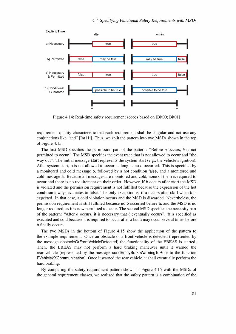
4.4 Specifying Functional Safety Requirements with MSDs
a) Necessary
b) Permitted
c) Necessary & Permitted
d) Conditional Guarantee
true
false
truefalse
after
true
false
true false
within
T T
may be true may be true
possible to be true possible to be true
Explicit Time
Figure 4.14: Real-time safety requirement scopes based on [Bit00; Bit01]
requirement quality characteristic that each requirement shall be singular and not use anyconjunctions like “and” [Int11i]. Thus, we split the pattern into two MSDs shown in the topof Figure 4.15.
The first MSD specifies the permission part of the pattern: “Before a occurs, b is notpermitted to occur”. The MSD specifies the event trace that is not allowed to occur and “theway out”. The initial message start represents the system start (e.g., the vehicle’s ignition).After system start, b is not allowed to occur as long as no a occurred. This is specified bya monitored and cold message b, followed by a hot condition false, and a monitored andcold message a. Because all messages are monitored and cold, none of them is required tooccur and there is no requirement on their order. However, if b occurs after start the MSDis violated and the permission requirement is not fulfilled because the expression of the hotcondition always evaluates to false. The only exception is, if a occurs after start when b isexpected. In that case, a cold violation occurs and the MSD is discarded. Nevertheless, thepermission requirement is still fulfilled because no b occurred before a, and the MSD is nolonger required, as b is now permitted to occur. The second MSD specifies the necessity partof the pattern: “After a occurs, it is necessary that b eventually occurs”. b is specified asexecuted and cold because it is required to occur after a but a may occur several times beforeb finally occurs.
The two MSDs in the bottom of Figure 4.15 show the application of the pattern tothe example requirement. Once an obstacle or a front vehicle is detected (represented bythe message obstacleOrFrontVehicleDetected) the functionality of the EBEAS is started.Then, the EBEAS may not perform a hard braking maneuver until it warned therear vehicle (represented by the message sendEmcyBrakeWarningToRear to the functionFVehicle2XCommunication). Once it warned the rear vehicle, it shall eventually perform thehard braking.
By comparing the safety requirement pattern shown in Figure 4.15 with the MSDs ofthe general requirement classes, we realized that the safety pattern is a combination of the
81

4 Specifying Formal Functional Safety Requirements
:Sender :Recipient
a
b
msd Beginnnig - Nec. & Perm. 5 (2)
:Sender :Recipient
b
msd Beginnnig - Nec. & Perm. 5 (1)
a
false
:Environment
start
:FEBEAS:FElectronic
StabilityControl
performHardBraking
msd Example (1)
:FAdaptiveCruiseControl
obstacleOrFrontVehicleDetected
:FVehicle2XCommunication
false
sendEmcyBrakeWarningToRear
:FEBEAS:FElectronic
StabilityControl
msd Example (2)
:FVehicle2XCommunication
sendEmcyBrakeWarningToRear
performHardBraking
(c,e)(h)
(c,m)
(c,m)
(h)
(c,m)
(c,m)(c,e)
Figure 4.15: Safety pattern “Beginning - Necessary & Permitted 5” as MSDs
two patterns Absence (After q until r) and Existence (After q). This mapping is depicted inFigure 4.16.
We found that all global and chronological succession safety requirement classes anda subset of the explicit time class can be expressed by (a combination of) the generalrequirement classes of Dwyer et al. and Konrad and Cheng. Table 4.3 shows the completemapping between the requirement classes. For example, the requirement patterns of theclasses Static and General Access Guarantee can be specified by a combination of patternsof the classes Universality, Existence, and Response with the scope Globally.
Unfortunately, most of the requirement patterns from the explicit time class could not bemapped to patterns of Dwyer et al. or Konrad and Cheng. Figure 4.17 shows the safety pattern“Explicit Time - Permitted 2” as an example of that. In textual form it is phrased as “Onlyafter T time units it is permitted that a occurs”. Figure 4.17 shows the MSD representationof this pattern and its application for the example requirement “Only 200 time units after thefunction FEBEAS sent the information sendEvadeWarningToOvertaking, it is permitted thatit sends the information steerForLaneChange”.
In the pattern MSD, the initial message startTimer is monitored and cold. It specifies theevent after which the time has to be measured. The message is followed by a hot clockcondition c > T. It describes the requirement’s if-condition – only if T time units passed. IfstartTimer occurs and T time units pass, a is allowed to occur. a is a monitored and coldmessage after the clock condition. It is not required to occur but if it occurs, it may not occurbetween startTimer and the clock condition evaluating to true. This order is encoded by theclock condition being hot and, thus, being required to occur strictly before a.
82

4.4 Specifying Functional Safety Requirements with MSDs
:Sender :Recipient
a
b
msd Beginnnig - Nec. & Perm. 5 (2)
:Sender :Recipient
b
msd Beginnnig - Nec. & Perm. 5 (1)
a
false
:Environment
start
:Sender :Recipient
q
p
msd Existence - After q
:Sender :Recipient
p
msd Absence - After q until r
r
false
:Environment
q
(c,e)(h)
(c,m)
(c,m)
(c,e)(h)
(c,m)
(c,m)
Figure 4.16: Safety pattern “Beginning - Necessary & Permitted 5” mapped to Absence(After q until r) and Existence (After q)
:Sender :Recipient
msd Explicit Time - Permitted 2
a
startTimer
c > T
:FEBEAS:FActive
FrontSteering
msd Example
:FVehicle2XCommunication
sendEvadeWarningToOvertaking
c > 200
steerForLaneChange
(h)
(c,m)
(h)
(c,m)
Figure 4.17: Safety pattern “Explicit Time - Permitted 2” (“Time-constrained Absence 2”) asMSD
83
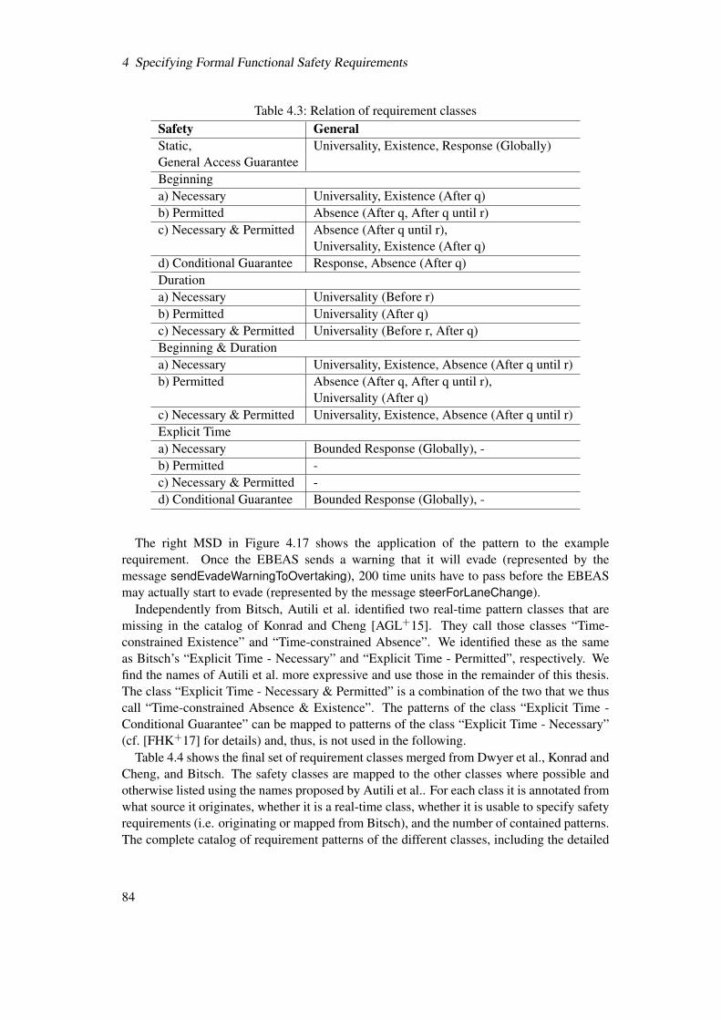
4 Specifying Formal Functional Safety Requirements
Table 4.3: Relation of requirement classesSafety GeneralStatic, Universality, Existence, Response (Globally)General Access GuaranteeBeginninga) Necessary Universality, Existence (After q)b) Permitted Absence (After q, After q until r)c) Necessary & Permitted Absence (After q until r),
Universality, Existence (After q)d) Conditional Guarantee Response, Absence (After q)Durationa) Necessary Universality (Before r)b) Permitted Universality (After q)c) Necessary & Permitted Universality (Before r, After q)Beginning & Durationa) Necessary Universality, Existence, Absence (After q until r)b) Permitted Absence (After q, After q until r),
Universality (After q)c) Necessary & Permitted Universality, Existence, Absence (After q until r)Explicit Timea) Necessary Bounded Response (Globally), -b) Permitted -c) Necessary & Permitted -d) Conditional Guarantee Bounded Response (Globally), -
The right MSD in Figure 4.17 shows the application of the pattern to the examplerequirement. Once the EBEAS sends a warning that it will evade (represented by themessage sendEvadeWarningToOvertaking), 200 time units have to pass before the EBEASmay actually start to evade (represented by the message steerForLaneChange).
Independently from Bitsch, Autili et al. identified two real-time pattern classes that aremissing in the catalog of Konrad and Cheng [AGL+15]. They call those classes “Time-constrained Existence” and “Time-constrained Absence”. We identified these as the sameas Bitsch’s “Explicit Time - Necessary” and “Explicit Time - Permitted”, respectively. Wefind the names of Autili et al. more expressive and use those in the remainder of this thesis.The class “Explicit Time - Necessary & Permitted” is a combination of the two that we thuscall “Time-constrained Absence & Existence”. The patterns of the class “Explicit Time -Conditional Guarantee” can be mapped to patterns of the class “Explicit Time - Necessary”(cf. [FHK+17] for details) and, thus, is not used in the following.
Table 4.4 shows the final set of requirement classes merged from Dwyer et al., Konrad andCheng, and Bitsch. The safety classes are mapped to the other classes where possible andotherwise listed using the names proposed by Autili et al.. For each class it is annotated fromwhat source it originates, whether it is a real-time class, whether it is usable to specify safetyrequirements (i.e. originating or mapped from Bitsch), and the number of contained patterns.The complete catalog of requirement patterns of the different classes, including the detailed
84

4.5 Integrating MBRE and NLRE for Safety Requirements Engineering
mapping of the safety requirement classes, can be found in [FHK+17]. The catalog consistsof 86 distinct requirement patterns with MSD examples (55 non-real-time and 31 real-timepatterns).
Table 4.4: Merged requirement pattern classesPattern Class Source Real-Time Safety CountOccurrence1. Existence [DAC99] - x 52. Bounded Existence [DAC99] - - 53. Time-constrained Existence [Bit00] x x 24. Bounded Recurrence [KC05] x - 55. Universality [DAC99] - x 56. Minimum Duration [KC05] x - 57. Maximum Duration [KC05] x - 58. Absence [DAC99] - x 59. Time-constrained Absence [Bit00] x x 2
10. Time-constrained Absence & Existence [Bit00] x x 2Order11. Response [DAC99] - x 512. Bounded Response [KC05] x x 513. Bounded Invariance [KC05] x - 514. Response Chain 1-n [DAC99] - - 515. Response Chain n-1 [DAC99] - - 516. Constrained Chain [DAC99] - - 517. Precedence [DAC99] - - 518. Precedence Chain 1-n [DAC99] - - 519. Precedence Chain n-1 [DAC99] - - 5
Total patterns: 86
4.5 Integrating MBRE and NLRE for Safety RequirementsEngineering
Model-based requirements engineering (MBRE) as used in the previous sections has manyadvantages over natural language requirements engineering (NLRE). For instance, theirsemi-formal or formal semantics allow model-based requirements to be automaticallyprocessed for verification and validation. On the contrary, informal natural language oftenintroduces ambiguity. Nevertheless, natural language can be used for any type of requirementwhilst model-based languages are tailored to specific types of requirements and need tobe learned before they can be used correctly. Thus, ISO 26262 proclaims that safetyrequirements shall be specified “by an appropriate combination of” natural language and“informal/semi-formal/formal notations for requirements specification” [Int11g]. Followingthis requirement, in this thesis, we use the formal, model-based language Modal Sequence
85

4 Specifying Formal Functional Safety Requirements
Diagrams, and show in this section, how it can be integrated with semi-formal and informalnatural language.
In previous work, we presented a combined MBRE-NLRE approach [FH14; FH15][FHM14; DFH+13]. It contains a so-called analysis model specified in a SysML blockdefinition diagram that similarly to the CONSENS function hierarchy decomposes therequired functionality of a system. In addition, textual requirement patterns in form of asemi-formal controlled natural language (CNL) are used to specify the analysis model andits requirements in natural language. A bidirectional transformation between the analysismodel and the natural language requirements keeps both representations in sync.
In this thesis, we adapt that approach to the used CONSENS function hierarchy extendedby ports and interfaces (cf. Section 4.3). Figure 4.18 sketches the resulting work productsand their relations. The top left represents the model-based function hierarchy as explainedin Section 4.3. The bottom left shows the model-based (safety) requirements specifiedas MSDs whose lifelines represent functions of the function hierarchy (cf. Section 4.4).The top right is a textual representation of the function hierarchy specified in a CNL.This representation can automatically be derived from its model-based equivalent using abidirectional transformation [FH14]. This transformation allows to synchronize changesin either representation with the other. The bottom right depicts textual requirements thathave no model-based representation but still address functions of the function hierarchy.This requirements representation is especially intended for types of requirements that are notexpressible with MSDs.
... ... ...
ID
1
2
3
... ...
Text
42
43
44
... ...
... ...
=
≠
CNLRequirements
Model-based Requirements
FunctionHierarchy
Functional (Safety) Requirements
Figure 4.18: Overview of MBRE-NLRE integration
All information contained in a model-based function hierarchy (as explained inSection 4.3) can be expressed in natural language using the eight requirement patterns RP 1to RP 8 listed below. They are adapted from requirement patterns published in [FHM14] tomatch the terms used in CONSENS.
86

4.5 Integrating MBRE and NLRE for Safety Requirements Engineering
Requirement Patterns for Function HierarchiesRP 1: The top-level function is called FUNCTION.RP 2: The function FUNCTION has the following purpose: PURPOSE.RP 3: The functional device FUNCTIONALDEVICE has the following purpose: PURPOSE.RP 4: The following information is received by the function FUNCTION [from the
functional device FUNCTIONALDEVICE]: INFORMATIONLIST.RP 5: The following information is sent from the function FUNCTION [to the functional
device FUNCTIONALDEVICE]: INFORMATIONLIST.RP 6: The function FUNCTION is a subfunction of the function PARENTFUNCTION.RP 7: The following information is used by the function FUNCTION: INFORMATIONLIST.RP 8: The following information is created by the function FUNCTION:
INFORMATIONLIST.
Requirement pattern RP 1 is used to specify the top-level root function of a functionhierarchy. RP 2 can be applied to summarize a function’s purpose. RP 3 does the samefor functions representing environment elements. RP 4 allows to specify information that thetop-level function receives from environment functions. RP 5 similarly specifies informationthe top-level function sends to the environment. RP 6 is used to specify a subfunction of a(top-level) function. RP 7 is used to specify input information that a subfunction uses. RP 8similarly is used to specify output information that a subfunction creates.
Figure 4.19 shows an example excerpt from the model-based function hierarchy of theEBEAS. The following requirements Req-1 to Req-18 form the CNL representation ofthat diagram. The textual chapter structure of the CNL requirements follows the modelstructure of the function hierarchy. This adheres to the organizational approach “FunctionalHierarchy” suggested by ISO 29148 for high-quality requirements specifications [Int11i].
«Function»FEBEAS
«Function»AnalyzeSituation
p4:FV2x2FEbeas
p2:FAcc2FEbeas
p6:~FEbeas2FV2x
p7:FAcc2FEbeas
bdd Functions
obstacleOrFrontVehicleDetected()
«interface»FAcc2FEbeas
sendEmcyBrakeWarningToRear()
«interface»FEbeas2FV2x
receivedEmcyBrakeRequestFromFront()receivedEmcyBrakeWarningFromFront()
«interface»FV2x2FEbeas
«Function»FACC
p1:~FAcc2FEbeas
«Function»FV2X
p3:~FV2x2FEbeas
p5:FEbeas2FV2x
«Function»Communicate
WithOtherVehiclesp8:~FEbeas2FV2x
Figure 4.19: Example excerpt from model-based function hierarchy for EBEAS
87

4 Specifying Formal Functional Safety Requirements
CNL Requirements for Function Hierarchy in Figure 4.19Req-1: 1 FEBEASReq-2: The top-level function is called FEBEAS.Req-3: 1.1 External ElementsReq-4: The functional device FACC has the following purpose: “It provides obstacle and
front vehicle information via sensors”.Req-5: The functional device FV2X has the following purpose: “It sends and receives V2V
messages”.Req-6: 1.2 Inputs & OutputsReq-7: The following information is received by the function FEBEAS from the functional
device FACC: obstacleOrFrontVehicleDetected.Req-8: The following information is received by the function FEBEAS from the functional
device FV2X: receivedEmcyBrakeRequestFromFront andreceivedEmcyBrakeWarningFromFront.
Req-9: The following information is sent from the function FEBEAS to the functionaldevice FV2X: sendEmcyBrakeWarningToRear.
Req-10: 1.3 SubfunctionsReq-11: 1.3.1 Analyze SituationReq-12: The function AnalyzeSituation is a subfunction of the function FEBEAS.Req-13: 1.3.1.1 Inputs & OutputsReq-14: The following information is used by the function AnalyzeSituation:
obstacleOrFrontVehicleDetected.Req-15: 1.3.2 Communicate With Other VehiclesReq-16: The function CommunicateWithOtherVehicles is a subfunction of the function
FEBEAS.Req-17: 1.3.2.1 Inputs & OutputsReq-18: The following information is created by the function
CommunicateWithOtherVehicles: sendEmcyBrakeWarningToRear.
Model-based (safety) requirements on the functions are specified using MSDs as describedin Section 4.4. In future work, textual patterns could be defined for the MSD patterns definedin Section 4.4.2. This could be based on existing textual patterns [KC05; AGL+15] andrequirements languages [GGK+16]. In addition to the requirement patterns described inSection 4.4.2, there are requirements that cannot be specified using MSDs. Examples arerequirements on the independence of functions (i.e., no cascading or common cause failuresas specified in Figure 3.15 on page 54). However, these can be specified using naturallanguage. Examples of according textual patterns and their application are shown below(RP 9 to RP 11 and Req-19 to Req-22).
Additional Requirement Patterns for FunctionsRP 9: There shall not be any cascading failures from the function FUNCTION1 to
FUNCTION2.RP 10: There shall not be any common cause failures of the functions FUNCTIONLIST.RP 11: The function FUNCTION shall FREETEXT.
88

4.6 Assumptions & Limitations
Additional CNL Requirements for Function Hierarchy in Figure 4.19Req-19: There shall not be any cascading failures from the function AnalyzeSituation to
CommunicateWithOtherVehicles.Req-20: There shall not be any cascading failures from the function
CommunicateWithOtherVehicles to AnalyzeSituation.Req-21: There shall not be any common cause failures of the functions AnalyzeSituation
and CommunicateWithOtherVehicles.Req-22: The function AnalyzeSituation shall . . .
4.6 Assumptions & Limitations
Assumptions
For the derivation of the top-level function hierarchy from the environment (cf.Section 4.3.1), we assume that the relevant input and output information is explicitly specifiedas CONSENS information flow (e.g., not implicitly hidden as energy flow).
Some of the requirement patterns of the MSD pattern catalog (cf. Section 4.4.2) are subjectto assumptions as documented in the corresponding technical report [FHK+17].
Limitations
ISO 26262 defines the concept of Safety Element out of Context (SEooC) (cf. Section 3.7). Ifa system like the EBEAS is not developed for a specific vehicle (i.e., context or environment),assumptions about its environment have to be made. Once the system is integrated into avehicle, these assumptions have to be checked for validity. An MSD specification can containso-called environment assumption MSDs [BGP13]. These are used to specify assumptionsabout the behavior of the environment. Thus, SEooC might also be tailored using the ASILtailoring process of this thesis, but they were not specifically considered.
If the MSD specification is hierarchically built up for the function hierarchy as describedin Section 4.3.3, a parallel simulation (play-out) of multiple function hierarchy levels iscurrently not possible. The followed approach of Holtmann and Meyer requires the useof UML interaction references to refine an MSD over different hierarchy levels [HM13].This constrains the refinement such that one MSD cannot be refined into a combination ofmultiple MSDs but has to be refined into a single MSD. Hence, we assume that each functionhierarchy level is simulated separately. In the end, the lowest level of functions specifies thefull functionality and only these functions are actually allocated to the system architecture.Thus, we argue that this constraint is acceptable. However, in future work, the play-outmaybe can be adapted to remove this constraint, e.g., by adopting the work of Atir et al.[AHK+08].
The integration of MBRE and NLRE described in Section 4.5 supports the bidirectionalsynchronization of the function hierarchy (model and text). The requirements specified withMSDs are not synchronized with a textual representation. However, in future work, textualpatterns could be defined for the MSD patterns defined in Section 4.4.2. This could be basedon existing textual patterns [KC05; AGL+15] and requirements languages [GGK+16].
89

4 Specifying Formal Functional Safety Requirements
4.7 Related Work
We divide the work related to our method for specifying functional (safety) requirements intothree categories: work related to the use of a function hierarchy (Section 4.7.1), to the use ofMSDs (Section 4.7.2), and to the integration of MSDs and natural language (Section 4.7.3).
4.7.1 Function Hierarchies
We use the so-called function hierarchy that is part of CONSENS [GRS14, Section 4.1]to decompose the complex functionality of cyber-physical systems and to structure thefunctional (safety) requirements. ISO 29148 suggests to use a functional structure todecompose requirements [Int11i]. Other model-based systems engineering approaches alsouse a functional abstraction of the system under development.
SYSMOD/FASSYSMOD [Wei14] and FAS [LW10] combined form a model-based systems engineeringmethod based on SysML. SYSMOD provides means to specify the system context,requirements, use cases and a physical architecture. FAS is embedded, and derives afunctional architecture from the SYSMOD use cases as basis for the SYSMOD physicalarchitecture [LW14]. The functions are derived by grouping use cases with high cohesion.The aim of the functional architecture is a solid model that abstracts from variations in thephysical architecture.
The SYSMOD system context is similar to the CONSENS environment and the physicalarchitecture to the CONSENS active structure. In contrast to how the CONSENS functionhierarchy is used in this thesis, SYSMOD/FAS links functions to use cases and not tofunctional requirements directly.
SPESThe SPES Modeling Framework [BDH+12] is a development methodology for software-intensive embedded systems. It is not based on a specific language like SysML. Itcomprises four viewpoints: the requirements, functional, logical, and technical viewpoint.The requirements viewpoint is used to specify model-based requirements. The functionalviewpoint starts with a functional black-box model consisting of user functions derivedfrom the requirements. It is followed by a functional white-box model to decompose userfunctions and the according system behavior [VEF+12]. The logical viewpoint specifies thelogical components of the system that are realized by software or hardware in the technicalviewpoint.
In previous work, we tailored the SPES modeling framework to the automotive domainand applied and evaluated it [FHH+12].
In contrast to CONSENS, SPES does not contain a specific environment or systemcontext viewpoint. This information is spread across the four existing viewpoints. Thefunctional viewpoint is similar to the CONSENS function hierarchy, but consists of twosub-models (black-box and white-box). The logical viewpoint is related to the CONSENSactive structure. The technical viewpoint describes discipline-specific details like softwarescheduling and deployment. Hence, there is no equivalent in CONSENS.
90

4.7 Related Work
EAST-ADLEAST-ADL is an architecture description language for automotive electronic systems[EAS13; BLH+13]. It is comprised of different modeling layers starting from vehiclefeatures, refined into a Functional Analysis Architecture, refined into a Functional DesignArchitecture, and ending with the software and hardware specification for the automotivespecific AUTOSAR framework (Automotive Open System Architecture)2. Orthogonal tothese layers EAST-ADL also contains environment, requirements, and dependability aspects.EAST-ADL provides a custom metamodel that is also available as UML profile [EAS10].
In contrast to CONSENS, EAST-ADL’s environment only contains elements in thesystem’s context and not the system itself. The elements of the environment are connected toelements in the functional analysis and the functional design architectures. In EAST-ADL,requirements are specified as nodes with text like in SysML. They can be hierarchicallystructured but that is not required.
The functional analysis architecture is related to the CONSENS function hierarchy. Itcontains functions that can be hierarchically decomposed and that interact via connectedports. These ports can specify flows or client-server interactions. In this thesis, we extendthe CONSENS function hierarchy by ports that specify abstract information flow, and do notconsider whether it is realized as energy flow or operations called by software. Furthermore,the functional analysis architecture also contains special types of functions to model sensorsand actuators. In contrast to EAST-ADL, we do not specify these details in the functionhierarchy but in the following CONSENS active structure. The latter is similar to EAST-ADL’s functional design architecture where decisions what is to be realized in software orhardware are documented.
As EAST-ADL is specifically developed for the automotive domain (especiallyAUTOSAR) its dependability part provides means to annotate ASILs to elements and tomodel failure propagation that can be analyzed by an external safety analysis tool [CJL+08].
SummaryThe three approaches SYSMOD/FAS, SPES, and EAST-ADL all have commonalities andslight differences to CONSENS and the way its function hierarchy is used in this thesis.All three provide a functional view of the system. In contrast to this thesis, SYSMOD/FASdoes not link the functions to requirements. The SPES functional viewpoint consists oftwo distinct sub-models for a black-box and white-box view and is not based on a standardmodeling language like SysML. EAST-ADL is specifically designed for the automotivedomain, and integrates technical interface information into its functional analysis architecturethat we explicitly abstract from.
SPES and EAST-ADL provide safety modeling and analysis means. However, only EAST-ADL integrates aspects for ASIL allocation. Although we use the automotive domain asrunning example in this thesis, our approach is designed to work for other safety-relevantdomains as well.
4.7.2 Formal Functional Safety Requirements
ISO 26262 highly recommends the use of semi-formal notations (e.g., UML) and semi-formal verification (e.g., “by executable models”) [Int11g]. The use of formal notations
2www.autosar.org
91

4 Specifying Formal Functional Safety Requirements
and formal verification is recommended by ISO 26262 [Int11g]. We use MSDs to specifygraphical, model- and scenario-based, formal functional (safety) requirements. MSDsintegrate with the semi-formal UML by a profile, and can be executed for semi-formalverification via play-out.
The Scenario Modeling Language (SML) is a textual, scenario-based formal notation[GGK+16]. It is based on MSDs, and supports semi-formal verification via play-out. Incontrast to MSDs, it is not a graphical language, and it has not been shown that it can expressthe requirement patterns from Section 4.4.2.
Computation Tree Logic (CTL) is a textual formal notation [EC82] that is widely used forformal verification. It can express all the non-real-time requirement patterns (cf. Table 4.4).Timed CTL is a formal notation that extends CTL with real-time capabilities [ACD93]. Itcan express all the real-time patterns. In contrast to MSDs, CTL and TCTL are neithergraphical nor scenario-based languages. Accordingly, they are not integrated with semi-formal notations like UML and do not support semi-formal verification.
Property Sequence Charts (PSC) are a graphical, scenario-based, formal notation [AIP07].They can be translated to CTL and express the general non-real-time patterns (cf. Table 4.1).Timed PSCs are a real-time extension of PSCs that can express the general real-time patterns[ZLG10]. In contrast to MSDs, it has not been shown that (T)PSCs can also express the safetypatterns (cf. Table 4.2). In addition, PSCs and TPSCs are not integrated with a semi-formalnotation like UML and do not support semi-formal verification.
4.7.3 MBRE-NLRE Integration for Safety
We integrate model-based safety requirements engineering with natural language safetyrequirements engineering by synchronizing the function hierarchy in its model-basedrepresentation with a textual representation in controlled natural language (CNL). Therequirement patterns introduced in Section 4.4.2 are expressed using MSDs, andrequirements that cannot be expressed using MSDs are specified in CNL.
Gordon and Harel generate Life Sequence Charts (basis of MSDs) from a CNL butprovide no transformation in the other direction [GH09]. A general survey on approachesthat generate models from natural language requirements has been conducted by Yue et al.[YBL11]. A survey for the reverse direction has been presented by Nicolás et al. [NT09].Both surveys did not find true synchronization approaches that transform in both directions.Furthermore, no approach specifically focuses safety requirements engineering.
4.8 Conclusion
This chapter describes the details how functional (safety) requirements are specified andrefined in the ASIL tailoring process introduced in Chapter 3. Section 4.2 specifies thecontents of a requirements specification. The functional (safety) requirements are derivedfrom the system’s environment and systematically structured and refined as described inSection 4.3. What types of requirements are relevant and how these can be expressedusing Modal Sequence Diagrams is explained in Section 4.4. For requirements that cannotbe expressed with MSDs, Section 4.5 specifies an integration of model-based and natural-language-based safety requirements engineering.
92

4.8 Conclusion
The model- and scenario-based, hierarchically decomposed specification of functionalsafety requirements provides a means to cope with the complexity of CPS functionalityand requirements (cf. Challenge C1 in Section 1.2). The formal specification of functionalsafety requirements with MSDs enables the automated safety analysis and ASIL allocationon requirements level (cf. Chapter 5). The catalog of formal, model-based MSD requirementpatterns for functional (safety) requirements supports requirements engineers and safetymanagers in building a high-quality requirements specification for a safe system. Theintegration of model-based requirements with natural language requirements fosters thecompleteness and consistency of requirements specifications whilst providing flexibility tospecify requirements in the respectively most suitable way.
The following Chapter 5 contains the details of the automated safety analysis and ASILallocation that is based on the function hierarchy and MSD requirements described in thischapter. In Chapter 6 an automatic documentation of safety arguments is elaborated thatlinks the hazards from the environment, the functions from the function hierarchy and thecorresponding MSD requirements.
93


5
SAFETY ANALYSIS AND ASIL ALLOCATIONON FUNCTIONAL SAFETY REQUIREMENTS
In Steps 2.3 and 2.4 of the ASIL tailoring process (cf. Figure 5.1), a safety analysis isperformed on the function hierarchy to allocate tailored ASIL values to the functions. Thischapter describes the details of these process steps and the used methods.
act ASIL Tailoring Process
Sys
tem
Des
igne
r,
Saf
ety
Man
ager
1. Analyze Environment and Hazards
2.3. GenerateFailure Propagation Model
for Function Hierarchy
2.4. CalculateASIL Allocation forFunction Hierarchy
2.2. Develop/Refine(Safety) Requirements
for Functions
3. Define System Architecture andAllocate Functions to System Elements
2.1. Develop/RefineFunction Hierarchy
CustomerRequirements
«datastore»System Architecture
Req
uire
men
ts E
ngin
eer,
Saf
ety
Man
ager
[functions sufficiently trivial and ASIL allocation reasonable]
«datastore»System
Requirements
FunctionHierarchy
FunctionHierarchy
FunctionHierarchy
Functional (Safety)Requirements
FSRs
Environment and Hazards with ASILs
System Elementswith ASILs
FailurePropagation
Model
FPM«datastore»Safety Case
Environment and Hazards with ASILsor Function Hierarchy [ASILs Tailored]
FunctionHierarchy
FunctionHierarchy
[ASILs Tailored]
Function Hierarchy[ASILs Tailored]
SafetyArgument
[else]
Figure 5.1: ASIL tailoring process with highlighted contents of Chapter 5
95

5 Safety Analysis and ASIL Allocation on Functional Safety Requirements
This chapter is structured as follows. First, Section 5.1 summarizes the scientificcontributions of safety analysis and ASIL allocation on functional safety requirements level.Section 5.2 explains Step 2.3 where a failure propagation model is generated from thefunction hierarchy and the functional (safety) requirements. In Section 5.3, Step 2.4 isdescribed where the failure propagation model is used to calculate valid ASIL tailoringsand allocate ASILs to the functions of the function hierarchy. Section 5.4 lists assumptionsand limitations of the presented safety analysis and ASIL allocation methods. In Section 5.5,related work is discussed. The final Section 5.6 concludes this chapter.
5.1 Contributions
The contributions of this chapter can be summarized as follows:
• Definition of a failure propagation meta model with static semantics for specifyingdifferent types of failures and their propagation through functions and functional(safety) requirements to the occurrence of hazards.
• Translation of ISO 26262’s informal ASIL tailoring rules to the failure propagationmeta model to enable automatic reasoning about validity of applied ASIL tailoringmeasures.
• Automatic derivation of failure propagation models from formal requirementsto reduce the effort and mistakes in safety analysis on functional requirements(Challenge C2 in Section 1.2).
• Automatic ASIL allocation to functions and functional (safety) requirements to reducethe effort and mistakes in ASIL allocation and tailoring on functional requirements(Challenge C2 in Section 1.2).
• Support for early identification of ASIL tailoring options, decision-making, andplanning of safety measures (Challenges C1 and C2 in Section 1.2).
5.2 Safety Analysis on Functional Requirements
In Step 1 of the ASIL tailoring process, hazards and their criticalities (ASIL) are identified(cf. Section 3.3). Hazards are caused by failures of the system. Hence, safety measureshave to be taken to avoid failures or mitigate their consequences. In Steps 2.1 and 2.2 of theASIL tailoring process, the functionality of the system under development is decomposed asfunction hierarchy, and corresponding requirements on the functions are specified as ModalSequence Diagrams (cf. Chapter 4). This supports the requirements engineer in handlingsystem complexity during analysis and validation of safety requirements.
Depending on a hazard’s ASIL, safety measures require a different level of effort. To plansafety efforts for individual system functions, it is required to know which hazards they areinvolved in. Consequently, the failure propagation from failures of a function through thefunction hierarchy to the hazards has to be determined.
A well-established method to determine failure propagation paths from a hazard down toits root cause failures is the Fault Tree Analysis (FTA, cf. Section 2.4.1). It is suitable for the
96

5.2 Safety Analysis on Functional Requirements
analysis of systems that are complex (cf. Challenge C1 in Section 1.2) and newly developedfrom scratch (e.g., CPS like autonomous driving). Furthermore, it is also suitable foranalyzing combinations of failures and for partitioning and allocating safety requirements.Other analysis methods like Event Tree Analysis [Eri05], FMEA [Int06a], or HAZOP [Int01]are considered unsuitable or are not recommended for this combination of purposes. Markovanalysis [Int06c] and petri-net analysis are suitable but require higher expertise and are lessaccepted than FTA. [Int03, Table 2]
Traditional fault trees are not strongly connected to the model that is analyzed.Specifically, they are not necessarily structured consistent to the model and provide no meansto follow the hierarchical structure of a function hierarchy. Hence, we use Component FaultTrees (cf. Section 2.4.2) in this thesis that add these features to traditional fault trees. In thisway, we gain a direct traceability between failures and inputs/outputs of functions.
In Step 2.3, a failure propagation model in form of Component Fault Trees is generatedfrom the function hierarchy and the functional (safety) requirements. Figure 5.2 shows thesub-actions of Step 2.3. Initially, in Step 2.3.1, the safety manager specifies a so-calledHazard CFT for each hazard. It defines what (combinations of) top-level function failurescause the respective hazard. Afterward, in Step 2.3.2, CFTs for the sub-functions of thefunction hierarchy are automatically generated based on the requirements specified as MSDs.These CFTs describe the failure propagation through the functions to the manually specifiedfailures of the Hazard CFTs. When changes to the function hierarchy or MSDs are made infurther iterations of the ASIL tailoring process, only the automated Substep 2.3.2 needs to berepeated.
2.3. Generate Failure Propagation Model
FunctionHierarchy
(Safety)MSDs
CFTs
2.3.2 GenerateCFTs
2.3.1 SpecifyHazard CFT
[no Hazard CFTspecified yet]
[else]
Figure 5.2: Process Step 2.3 - Generate Failure Propagation Model for Function Hierarchy
The following Section 5.2.1 describes how CFTs and different types of failures arespecified in this thesis. The details of Step 2.3.1 and Hazard CFTs are explained inSection 5.2.2. The CFT generation of Step 2.3.2 is elaborated in Section 5.2.3.
97
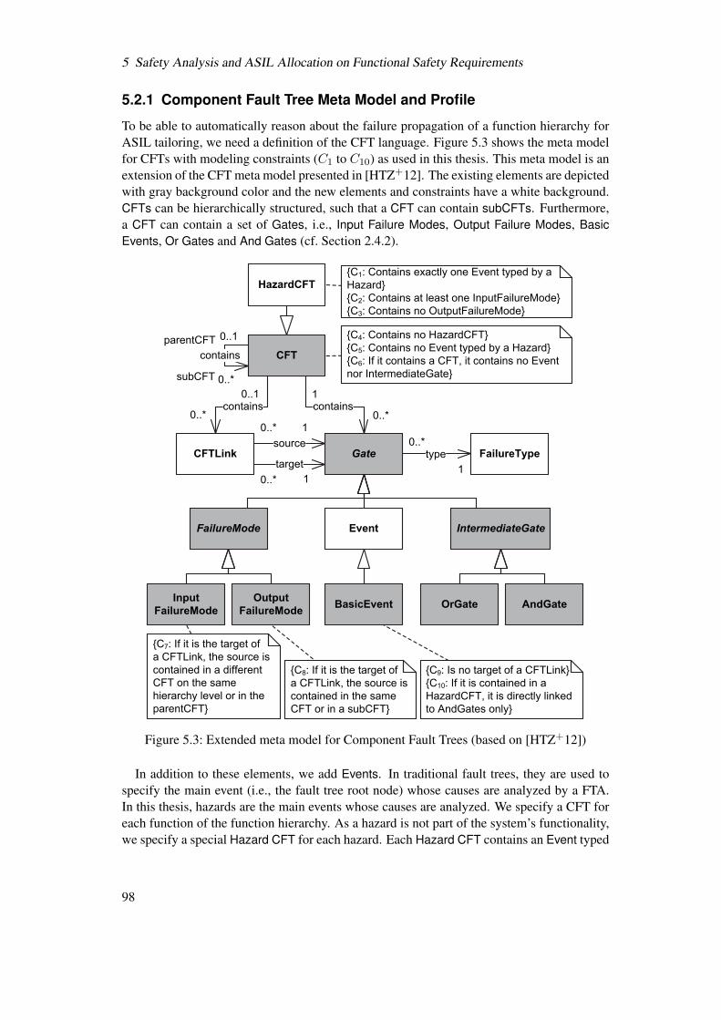
5 Safety Analysis and ASIL Allocation on Functional Safety Requirements
5.2.1 Component Fault Tree Meta Model and Profile
To be able to automatically reason about the failure propagation of a function hierarchy forASIL tailoring, we need a definition of the CFT language. Figure 5.3 shows the meta modelfor CFTs with modeling constraints (C1 to C10) as used in this thesis. This meta model is anextension of the CFT meta model presented in [HTZ+12]. The existing elements are depictedwith gray background color and the new elements and constraints have a white background.CFTs can be hierarchically structured, such that a CFT can contain subCFTs. Furthermore,a CFT can contain a set of Gates, i.e., Input Failure Modes, Output Failure Modes, BasicEvents, Or Gates and And Gates (cf. Section 2.4.2).
CFT
HazardCFT
CFTLink
Event
BasicEvent
IntermediateGateFailureMode
OrGate AndGate
Gate FailureType
InputFailureMode
OutputFailureMode
{C1: Contains exactly one Event typed by a Hazard}{C2: Contains at least one InputFailureMode}{C3: Contains no OutputFailureMode}
{C4: Contains no HazardCFT}{C5: Contains no Event typed by a Hazard}{C6: If it contains a CFT, it contains no Event nor IntermediateGate}subCFT
parentCFT 0..1
0..*
contains
0..1
0..*contains
1
0..*contains
0..*
1
type
10..*
source
10..*
target
{C9: Is no target of a CFTLink}{C10: If it is contained in a HazardCFT, it is directly linked to AndGates only}
{C7: If it is the target ofa CFTLink, the source is contained in a different CFT on the same hierarchy level or in the parentCFT}
{C8: If it is the target ofa CFTLink, the source is contained in the same CFT or in a subCFT}
Figure 5.3: Extended meta model for Component Fault Trees (based on [HTZ+12])
In addition to these elements, we add Events. In traditional fault trees, they are used tospecify the main event (i.e., the fault tree root node) whose causes are analyzed by a FTA.In this thesis, hazards are the main events whose causes are analyzed. We specify a CFT foreach function of the function hierarchy. As a hazard is not part of the system’s functionality,we specify a special Hazard CFT for each hazard. Each Hazard CFT contains an Event typed
98

5.2 Safety Analysis on Functional Requirements
by the hazard and specifies what Output Failure Modes of the top-level CFT cause the hazard(cf. constraints C1 to C6 and C10). In contrast to [HTZ+12], we specify the connectionsbetween Gates explicitly in the meta model as CFT Link. This allows to specify constraints,in what situations different types of Gates may be linked (cf. constraints C7 to C9).
Furthermore, we add Failure Types as type for Gates. Thereby, failures like omission andcommission can be distinguished. Figure 5.4 shows the failure types used in this thesis. Thefailure types are based on the failure type hierarchy of Giese et al. who distinguish service,value, and timing failures [GTS04] (also defined in [ALR+04]):• Omission (O): An expected event does not occur.• Commission (C): An event occurs unexpectedly or unintentionally.• Crash (Cr): A function stops to deliver service (e.g., software crashes).• Value (V): An event occurs with an unexpected content (e.g., parameter value).• Timing Early (TE) / Late (TL): An event occurs too early / too late.
For a better diagram overview, we use the abbreviations shown below each failure type in thisthesis, and also depict them inside the triangular failure modes of the CFT concrete syntax.
«FailureType»FailureType
«FailureType»Service
FailureType
«FailureType»Value
FailureType
«FailureType»Timing
FailureType
«FailureType»Omission
FailureType
«FailureType»CommissionFailureType
«FailureType»TimingEarlyFailureType
«FailureType»TimingLateFailureType
O C TE TL
V
«FailureType»Crash
FailureType
Cr
bdd CFT Failure Types
Figure 5.4: Failure type library model for gates
The input models for generating the CFT failure propagation model are specified inSysML/UML. The function hierarchy is specified using the SysML4CONSENS profile andMSDs using a profile for UML sequence diagrams. To model failure propagation in thesame language with easy traceability to the other models and to be able to use the sametool, we consequently specify a UML profile for Component Fault Trees. Figure 5.5 showsthe CFT profile definition derived from the meta model in Figure 5.3, and Figure 5.6 showsan example CFT in abstract syntax (bare application of the CFT UML profile) and in theconcrete syntax used throughout this thesis (an integration of the CFT syntax and UML). ACFT is a special UML Class whose Ports represent Failure Modes. Output failure modesare specified as conjugated ports, input failure modes are not conjugated. Events, BasicEvents, OR-gates, and AND-gates are specialized UML Properties. All gates are connectedvia directed CFT Links specializing UML Dependencies. The CFT meta model constraints
99

5 Safety Analysis and ASIL Allocation on Functional Safety Requirements
C1 to C10 are realized as OCL constraints in the profile. In the CFT meta model, gates aretyped by failure types. When using the UML profile, a Gate’s failure type is specified by theUML type of its Port or Property. The failure types shown in Figure 5.4 are specified usingthe UML profile. We specify the failure types in a library model, not as part of the UMLprofile, to make them extensible for different application domains (e.g., [MZH+16]).
«profile» UML4CFT
«Metaclass»Class
«Metaclass»Property
«Stereotype»CFT
«Metaclass»Port
«Stereotype»HazardCFT
«Metaclass»Dependency
«Stereotype»CFTLink
«Stereotype»Event
«Stereotype»BasicEvent
«Stereotype»IntermediateGate
«Stereotype»FailureMode
«Stereotype»OR
«Stereotype»AND
«Stereotype»Gate
«Stereotype»FailureType
Figure 5.5: UML Profile for Component Fault Trees
A CFT specifies the failure propagation of a function. The CFT Make DecisionCFT in Figure 5.6 specifies the failure propagation through the function MakeDecision. Its failure modes represent failures of the corresponding function’s inputand output information grouped by the function’s port interfaces. The failure modeactivateEmergencyBraking:∼O specifies that the function Make Decision does not send theinformation activateEmergencyBraking over its port p4 when expected. It is caused either bya crash :Cr of the function or by the two omission failures reachingLastPointToBrake:O andreceivedEmcyBrakeWarning:O occurring at once (specified by the combining AND-gate).
100

5.2 Safety Analysis on Functional Requirements
«Function»FEBEAS
reachingLastPointToBrake()...
«interface»SituationalEvents «Function»
MakeDecision
p2:~CommDecisions
p4:~ActingDecisions
p1:ReceivedMessages
p3:SituationalEvents
sendEmcyBrakeWarning()...
«interface»CommDecisions
activateEmergencyBraking()...
«interface»ActingDecisions
receivedEmcyBrakeWarning()...
«interface»ReceivedMessages
«CFT» MakeDecisionCFT
o
:Cr
«OR»
oo
«AND»
o
reachingLastPointToBrake:O
receivedEmcyBrakeWarning:O
«trace»
«trace»
«trace»«trace»
«trace»
sendEmcyBrakeWarning:~O
«CFT» MakeDecisionCFT
«OR»or:FailureType
«AND»and:FailureType
«BasicEvent»:Cr
«CFTLink»«CFTLink»
«FailureMode»activateEmergency
Braking:~O
«FailureMode»sendEmcyBrakeWarning:~O
«FailureMode»receivedEmcy
BrakeWarning:O
«FailureMode»reachingLast
PointToBrake:O
«CFTLink»
«CFTLink» «CFTLink»
«CFTLink»
Abstract Syntax (bare applied UML profile)
Concrete Syntax
activateEmergencyBraking:~O
Figure 5.6: Example CFT for function Make Decision in concrete and abstract syntax
101

5 Safety Analysis and ASIL Allocation on Functional Safety Requirements
5.2.2 Linking Hazards to Failures
In Step 1 of the ASIL tailoring process, hazards are specified, and in Step 2.1, the functionhierarchy is specified. Hazards occur if the system under development fails to deliver itsservice, i.e., does not provide its functionality as expected. So, in terms of the functionhierarchy, a hazard occurs if an output information of the top-level function has a failure(e.g., is omitted when expected).
Figure 5.7 shows an example hazard from Step 1 and its relation to CFTs and the functionhierarchy from Step 2.1. The hazard Hard Braking Omission describes that the vehicledoes not perform a hard braking in case of an obstacle, because the EBEAS fails to senda respective brake request to the ESC (cf. Figure 3.4 on page 44). In Step 2.3.1 of thetailoring process, this relation between hazard and brake request failure is specified by thesafety manager in form of the Hazard CFT Hard Braking Omission CFT. It contains a CFTevent :HardBrakingOmission that represents the occurrence of the hazard (because its type isset to the hazard). The brake request is represented as the information performHardBrakingsent by the top-level function FEBEAS. Therefore, the safety manager specifies its failure asinput omission failure mode performHardBraking:O of the Hazard CFT, and links it to theCFT event representing the hazard occurrence.
Id = “H1“Text = “Missing automatic hard braking.“ASIL = ASIL D
«Hazard»HardBrakingOmission
«CFT»FEBEASCFT
«HazardCFT»HardBrakingOmissionCFT
«Event»:HardBraking
Omission
«Function»FEBEAS
:~Ebeas2Esc
performHardBraking()
«interface»Ebeas2Esc
«trace»
«trace»
«trace»
Step 1 Step 2.3.1
Step 2.1 Step 2.3.2
performHardBraking:~O
o
o
performHardBraking:O
Figure 5.7: Example Hazard CFT for hazard Hard Braking Omission
Hazard CFTs can contain the same gates as CFTs (except for output failure modes). If ahazard is caused by different failures or only by certain combinations of failures, this can bespecified by using OR and AND gates. The CFTs for the function hierarchy (FEBEAS CFTin Figure 5.7) with their failure modes and internal structure are automatically generated andlinked to the failure modes of Hazard CFTs in Step 2.3.2 of the tailoring process. The detailsof this step are described in the following section.
102

5.2 Safety Analysis on Functional Requirements
5.2.3 Generating Component Fault Trees
We express the failure propagation through the function hierarchy by Component Fault Trees.In Step 2.3.2 of the ASIL tailoring process, they are automatically derived from the functional(safety) requirements specified as Modal Sequence Diagrams (cf. Section 4.4). Figure 5.8sketches this CFT generation by an example. The top diagram is an MSD that specifies therequirement that the function Make Decision shall decide to activate emergency braking onceit is informed that the vehicle is reaching the last point to brake. The bottom diagram showsthe function’s corresponding CFT Make Decision CFT with its failure modes and internalelements generated from the MSD above.
«CFT»MakeDecisionCFT
o c
o c
:Cr
ibd Failure Propagation
«OR»
msd Brake Requirement
:MakeDecision
:EnsurePassenger
Safety
activateEmergencyBraking
:AnalyzeSituation
reachingLastPointToBrake
(c,e)
reachingLastPointToBrake:O
reachingLastPointToBrake:C
activateEmergencyBraking:~C
activateEmergencyBraking:~O
Figure 5.8: Example of CFT generation for function Make Decision
If the function Make Decision fails when the vehicle reaches the last point tobrake, it will not send the information activateEmergencyBraking. In other words,
103

5 Safety Analysis and ASIL Allocation on Functional Safety Requirements
the information activateEmergencyBraking is omitted (O) if the function crashes (Cr)between the receiving of the information reachingLastPointToBrake and the sendingof activateEmergencyBraking. This is specified by the basic event :Cr linked tothe output failure mode activateEmergencyBraking:∼O. In addition, if the informationreachingLastPointToBrake is not received by Make Decision, the function will not sendthe information activateEmergencyBraking. This is specified by the input failure modereachingLastPointToBrake:O linked to activateEmergencyBraking:∼O. As both the crash andthe input failure cause the output omission failure individually (single-point failures), theyare connected to the output failure via an OR gate.
If the information reachingLastPointToBrake is received unexpectedly by Make Decisionbecause Analyze Situation sends it unintentionally (C), Make Decision will send theinformation activateEmergencyBraking as normal reaction adhering to the requirement. Thispropagates the commission failure from Analyze Situation through Make Decision. It isspecified by the input failure mode reachingLastPointToBrake:C linked to the output failuremode activateEmergencyBraking:∼C.
Section 4.4.2 lists patterns of functional requirements and functional safety requirementsexpressible with MSDs. These patterns were consolidated from different sources thatidentified them in industry requirements specifications. Hence, we assume these patternsrepresent all relevant types of functional (safety) requirements. Consequently, we assumethat all MSD specifications, that we derive CFTs from, solely consist of MSDs applyingthose patterns. From a systematic analysis of all MSD requirement patterns we derivedrules for the generation of CFTs as sketched in Figure 5.8. For omission and commissionfailures we identified eight cases of MSDs in the patterns that we group into positive andnegative MSDs. Positive MSDs specify information exchange that shall occur. NegativeMSDs specify information exchange that must not occur. Negative MSDs can be identifiedby a contained hot-false-condition, i.e., a hot condition with the expression “false” that cannever evaluate to true. Figure 5.9 shows the four positive MSD cases and the respective CFTelements. Figure 5.10 shows the four negative MSD cases and the respective CFT elements.
Case 1 specifies the requirement excerpt “If the considered lifeline :L sends the informationq, followed by sending/receiving arbitrary further information, then :L has to send theinformation p”. In this case, :L might crash between sending q and p resulting in an omissionfailure of p. Case 1 results in no commission failure of p because :L receives no informationthat could have a commission failure that would propagate to p. A commission failure of pwould have the same cause as the commission failure of q, and that cause is not visible inthis case’s MSD.
Case 2 is similar to Case 1 with the difference that initially the considered lifeline :Lreceives the information q. In that case, again :L might crash between q and p resulting inan omission failure of p. In addition, that omission might also be caused by an omission ofthe ingoing information q. If q has a commission failure, it will propagate through L to acommission failure of p, because that information would be correctly sent according to theMSD requirement.
Case 3 specifies the requirement excerpt “If the considered lifeline :L sends/receives oneor more information, followed by receiving the information s, followed by sending/receivingarbitrary further information, then :L has to send the information p”. This case describes thefact that a required information p (then-part of the requirement) would not be sent by :L ifan information on its prechart (if-part of the requirement) is not received by :L. The prechart
104

5.2 Safety Analysis on Functional Requirements
msd MSD Case 4
:L :T
p
:S
q
(*,m)
...
s
...
(h,*)
«CFT»LCFT
o c
o c
:Cr
ibd Failure Propagation Case 2
«OR»
p:~Cp:~O
msd MSD Case 3
:L :T:S
(*,e)
...
s
...
(c,m)
«CFT»LCFT
o
o
ibd Failure Propagation Case 3
p:~O
«CFT»LCFT
o
:Cr
ibd Failure Propagation Case 4
p:~O
msd MSD Case 2
:L :T
p
:S
q
(*,e)
...
msd MSD Case 1
:L :T
p
q
(*,e)
...
«CFT»LCFT
o
:Cr
ibd Failure Propagation Case 1
p:~O
Pre
char
t of p
Pre
char
t of p
s:O
q:Cq:O
Figure 5.9: CFT generation cases for positive MSDs
105
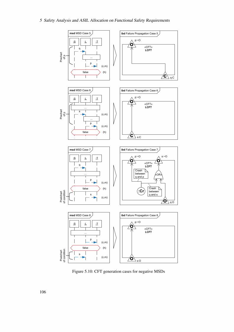
5 Safety Analysis and ASIL Allocation on Functional Safety Requirements
msd MSD Case 5
:L :T:S
q
(h)
...
p(c,m)
false
msd MSD Case 6
:L :T:S
s
(h)
...
p(c,m)
false
msd MSD Case 8
:L :T:S
(h)
...
p(c,m)
false
s(c,m)
«CFT»LCFT
o
c
ibd Failure Propagation Case 5
p:~O
...
(c,m)
«CFT»LCFT
o
c
ibd Failure Propagation Case 6
p:~O
msd MSD Case 7
:L :T:S
q
(h)
...
p(c,m)
false
s(c,m)
«CFT»LCFT
o
:Cr
ibd Failure Propagation Case 7
Crashbetweenq and p
p:~O
«CFT»LCFT
o
o
ibd Failure Propagation Case 8
p:~O
o
o
«OR»
Crashbetweenq and s
s:~O
Pre
char
tof
pP
ostc
hart
of c
ondi
tion
Pos
tcha
rtof
con
ditio
n
q:O
s:O
s:C
q:C
Pre
char
tof
p
Figure 5.10: CFT generation cases for negative MSDs
106

5.2 Safety Analysis on Functional Requirements
of an MSD element consists of all elements above it on all lifelines. Case 3 results in nocommission failure of p because s is not the minimal message of the MSD that triggers theevaluation of the requirement. The commission of s without the commission of the MSD’sminimal message would not lead to p being sent unintentionally.
Case 4 specifies the requirement excerpt “If the considered lifeline :L receives theinformation q, followed by sending/receiving arbitrary further information, followed bysending the information s in strict order related to all other information in the MSD, followedby sending/receiving arbitrary further information, then the information p may be sent by:L”. In this case, :L might crash between sending q and p resulting in an omission failureof p (although p is not required because it is monitored). If p is required by some otherMSD, it is blocked by this MSD once the execution reaches s. Then, p is not allowed tooccur until s occurred. If :L crashes before s occurs, p will not be sent. Case 4 results in nocommission failure of p because it is not required to occur (not executed but monitored), it isonly restricted.
The Cases 1 to 4 prescribe the rules for generating CFTs from positive MSDs. Theserules are aggregated as pseudo code in Algorithm 5.1. This algorithm was appliedin Figure 5.8. The top diagram in the figure is a Case 2 MSD. The failure modeactivateEmergencyBraking:∼O and the the basic event :Cr are created and linked by line 6of Algorithm 5.1. The failure mode reachingLastPointToBrake:O is created and linked to thealready created failure mode activateEmergencyBraking:∼O by line 9. The failure modesactivateEmergencyBraking:∼C and reachingLastPointToBrake:C are created and linked byline 10.
Algorithm 5.1 Creation of O and C failures from positive MSDs1: m := the considered positive MSD2: for all lifelines l of m do3: for all messages p sent by l do4: if p is executed then5: if the minimal message of m is received/sent by l then . Cases 1 and 26: Create failure mode p:∼O caused by basic event :Cr of l7: end if8: if the minimal message q of m is received by l then . Case 29: Create failure mode p:∼O caused by failure mode q:O
10: Create failure mode p:∼C caused by failure mode q:C11: end if12: for all (c,m) messages s received by l on the prechart of p do . Case 313: Create failure mode p:∼O caused by failure mode s:O14: end for15: else . p is monitored16: if the prechart of p contains a hot message sent by l then . Case 417: Create failure mode p:∼O caused by basic event :Cr of l18: end if19: end if20: end for21: end for
107

5 Safety Analysis and ASIL Allocation on Functional Safety Requirements
The four cases for negative MSDs are shown in Figure 5.10. Case 5 specifies therequirement excerpt “If the considered lifeline :L receives the information q, followed bysending arbitrary further information, then :L must not send the information p”. In this case,the information p might be unintentionally forbidden if the last input to :L q (which is alsothe minimal message) is unexpectedly received by :L. Therefore, a commission failure of qresults in an omission failure of p.
Case 6 specifies the requirement excerpt “If the considered lifeline :L sends/receives oneor more information, followed by receiving the information s, followed by sending arbitraryfurther information, then :L must not send the information p”. This case is similar to Case 5,except that s is not the minimal message but any other last input to :L on the prechart ofp. Accordingly, the omission failure of p is caused by this last input s instead of a minimalmessage that is possibly received by :L.
Case 7 specifies the requirement excerpt “If the considered lifeline :L receives theinformation q, followed by sending/receiving arbitrary further information, then :L must notsend the information p unless it sends s before”. This case describes the scenario that pis forbidden after the minimal message q until any information s from the postchart of thehot-false-condition is sent. The postchart of an MSD element consists of all elements belowit on all lifelines. In this case, p is only unintentionally forbidden if no information s fromthe postchart of the hot-false-condition is sent. That is only the case if L crashes. Hence,an omission failure of p is caused by a crash of L. Any information s on the postchart of thehot-false-condition might be omitted if the minimal message q is not occurring and triggeringthis requirement or if :L crashes before it can send s.
Case 8 specifies the requirement excerpt “If the considered lifeline :L sends/receives oneor more information, then :L must not send the information p until it receives s”. In thiscase, p might be forbidden longer than intended if any information s on the postchart of thehot-false-condition is unexpectedly not received. Hence, an omission failure of p is causedby an omission failure of s.
All negative MSD cases do not lead to output commission failures because they are onlyrestricting information exchange (i.e., negative MSDs contain no executed messages). TheCases 5 to 8 prescribe the rules for generating CFTs from negative MSDs. These rules areaggregated as pseudo code in Algorithm 5.2.
Algorithms 5.1 and 5.2 create failure modes, basic events, and their connections treatingevery input failure mode and basic event as single-point failure. However, some requirementsmay be redundant such that two or more input failures have to occur at the same time for anoutput failure to occur (multiple-point failure). Single-point failures are merged by an ORgate, whereas multiple-point failures have to be merged by an AND gate. Hence, we applyanother transformation step (Algorithm 5.3) to identify redundant requirements and updatethe CFT internals accordingly.
Figure 5.11 shows an example of redundant requirements, the resulting CFT afterexecution of Algorithm 5.1, and the final CFT with integrated AND gates by Algorithm 5.3.The first MSD G’1 specifies the requirement that mf shall be sent if mg1 is received. Thesecond MSD G’2 specifies that mf shall be sent if mg2 is received. So, these two MSDsform redundant requirements with the two inputs mg1 and mg2 that redundantly require thesending of mf. The third MSD G’3 specifies the requirement that mf shall be sent if mg3 isreceived and followed by mg4. This is a third redundant requirement with the difference that
108

5.2 Safety Analysis on Functional Requirements
Algorithm 5.2 Creation of O and C failures from negative MSDs1: m := the considered negative MSD2: c := the hot-false-condition of m3: p := the message directly followed by c4: l := the lifeline p is sent by5: if postchart of c is empty then6: for all messages s received by l on the prechart of p do . Cases 5 and 67: if s is the last ingoing message of l on the prechart of p then8: Create failure mode p:∼O caused by failure mode s:C9: end if
10: end for11: else . There are messages after c12: if the postchart of c contains messages sent by l then . Case 713: Create failure mode p:∼O caused by basic event :Cr of l14: for all messages s on the postchart of c sent by l do15: Create failure mode s:∼O caused by basic event :Cr of l16: if the minimal message q of m is received by l then17: Create failure mode s:∼O caused by failure mode q:O18: end if19: end for20: end if21: for all messages s on the postchart of c received by l do . Case 822: Create failure mode p:∼O caused by failure mode s:O23: end for24: end if
Algorithm 5.3 Creation of AND gates for ∼O failures
1: for all ∼O failures f of a CFT c do2: I := all input failure modes of c on the path to f3: G := failure modes of I grouped by MSD that they originate from4: if G contains more than one group then . AND gate(s) required5: Remove the current links of all failure modes g ∈ G towards f6: A := {} . The set of created AND gates7: P :=
∏G′∈GG′
8: for all cartesian products of failure modes P ′ ∈ P do9: Link all g ∈ P ′ to a new AND gate a
10: Add a to A11: end for12: Link all a ∈ A to output failure mode f (or its preceding OR gate if existing)13: end if14: end for
109

5 Safety Analysis and ASIL Allocation on Functional Safety Requirements
the combination of the two inputs mg3 and mg4 is redundant to the inputs mg1 and mg2from the other MSDs.
Algorithm 5.1 identifies Case 2 in all three MSDs and additionally Case 3 in MSD G’3.Therefore, its result is the intermediate CFT in the middle of Figure 5.11 with a crash basicevent and four input omission failure modes for each of the four input messages. Eachof these failures could be involved in an omission of the output mf, and thus they are allconnected to the output omission failure mf:∼O via an OR gate.
Algorithm 5.3 separates the four input failure modes into three groups according to theMSDs that they originate from. Because each MSD is redundant to the others, a failurefrom each group of failure modes has to occur simultaneously for the output failure tooccur. Hence, the algorithm creates an AND gate for each combination (cartesian product)of redundant failure modes. The CFT in the bottom of Figure 5.11 shows the result ofAlgorithm 5.3 which is the final result of the CFT generation with consideration of redundantrequirements.
The prototypical implementation of the algorithms is described in Section 7.1. Thatimplementation was used to validate that the transformation rules (the eight cases) arecomplete and to verify the correctness of the algorithms by testing the implementation againstthe patterns of the MSD pattern catalog (cf. Section 4.4.2) and the expected CFT outputs.
5.3 ASIL Allocation on the Function Hierarchy
The function hierarchy decomposes the functionality of the system under development andstructures the functional (safety) requirements. The CFTs generated from the functionhierarchy and its requirements specify the failure propagation from input and basic failuresof the system to output failures causing hazards. Different hazards have different criticalityspecified by their ASIL value. In general, each function has to be developed in accordancewith the maximum ASIL of all identified hazards. Thereby making sure that it is developedwith the required degree of rigor to avoid or mitigate the hazards. If ASIL tailoring shall beapplied to develop a function with lower degree of rigor, the validity of the tailoring has tobe checked.
To fulfill these requirements and find a valid ASIL allocation to functions, we calculatethe ASIL propagation from hazards over the failure modes of the CFTs. Afterward, wederive the ASIL of each function based on the ASILs allocated to its corresponding CFT. Allthis is done automatically in Step 2.4 of the ASIL tailoring process. Figure 5.12 shows thesub-actions of that step.
In Step 2.4.1, ASILs are calculated for each failure mode of the CFTs based on the hazardsthat they are involved in. The details of this step are described in the following Section 5.3.1.Afterward, in Step 2.4.2, ASILs are allocated to functions and their requirements based onthe ASILs calculated for the CFT failure modes. The details of this step are explained inSection 5.3.2. When changes to the function hierarchy or requirements are made in furtheriterations of the ASIL tailoring process, these automated steps can be repeated. In Step 2.4.3the validity of the ASIL allocation is documented. This is explained in Chapter 6.
110

5.3 ASIL Allocation on the Function Hierarchy
msd G‘1
:L
mf
mg1
(c,e)
msd G‘2
:L
mf
mg2
(c,e)
msd G‘3
:L
mf
mg3
(c,e)
mg4(c,m)
«CFT»LCFT
o
o:Cr
ibd Intermediate Failure Prop.
«OR»
mf:~O
omg1:O mg2:O
omg3:O
omg4:O
«CFT»LCFT
o
o
:Cr
ibd Final Failure Propagation
«OR»
mf:~O
omg1:O mg2:O
omg3:O
omg4:O
«AND»
Algorithm 5.1
Algorithm 5.3
Case 3Case 2
«AND»
Figure 5.11: Example of CFT generation for ∼O failure and redundant MSDs
111

5 Safety Analysis and ASIL Allocation on Functional Safety Requirements
2.4. Calculate ASIL Allocation
CFTs
Function Hierarchy
Function Hierarchywith ASILs
2.4.1 CalculateASILs for
Failure Modes2.4.3 Generate
Safety Argument
2.4.2 AllocateASILs to
Functions
SafetyArgument
Figure 5.12: Process Step 2.4 - Calculate ASIL Allocation for Function Hierarchy
5.3.1 Calculating ASILs on CFTs
The failure propagation model consists of hierarchically structured CFTs that represent thefailure propagation of the function hierarchy. In addition, the model contains Hazard CFTsthat specify what failures of the top-level CFT cause hazards. Figure 5.13 shows a sketch ofa failure propagation model. The hazard h1 is caused by failure o1 of CFT c1. The hazard h2is caused by failure o2 of CFT c1. Each hazard has an ASIL value that specifies its safety-criticality. In Figure 5.13, h1 has ASIL D and h2 has ASIL C. Thus, by default, the CFTc1 and all its sub-CFTs inherit the maximum ASIL of both hazards, i.e., ASIL D. If ASILtailoring is applied, some CFTs can be allocated with a lower ASIL than others (cf. c3 andc5). This ASIL reduction has to follow the rules defined by ISO 26262.
5.3.1.1 ASIL Tailoring Rules
ASIL tailoring can be done by applying one of the two measures separation anddecomposition. Both measures are applied on requirements. In separation, safetyrequirements with lower criticality are separated from requirements with higher criticalityby allocating them to different functions, such that the more critical function is freeof interference from the less critical function (cf. Definition 2.24 on page 25). Indecomposition, a safety requirement with higher criticality is decomposed into a setof redundant requirements that are allocated to sufficiently independent functions (cf.Definition 2.26 on page 26). Hence, each redundant requirement may be considered lesscritical because all requirements have to fail at once to violate the original requirement.
ASIL tailoring by separation or decomposition has to obey the rules of ISO 26262described in Section 2.5. In the following, we transfer those rules to the elements of the CFTfailure propagation meta model. Each CFT specifies the failure propagation of a function.The failure propagation inside a CFT is specified by a set of linked gates and is derivedfrom the requirements as explained in Section 5.2.3. If a CFT’s output failure mode occurs,the corresponding requirement of a function is violated. Definition 5.1 specifies the basicelements of a failure propagation model and their relations.
112

5.3 ASIL Allocation on the Function Hierarchy
«CFT» {ASIL D}
c1
«CFT» {ASIL D}
c2«AND»
{ASIL D}
a1
«AND»{ASIL C}
a2
«CFT»{ASIL A(D)}
c3
«CFT»{ASIL C(D)}
c4
«CFT»{ASIL C}
c5
«HazardCFT» «HazardCFT»
{ASIL D}h1
{ASIL C}h2
{ASIL C} i2
{ASIL C}{ASIL C(D)}i9
{ASIL C(D)}o6 {ASIL C}
{ASIL C} o4
{ASIL A(D)}o5
{ASIL A(D)}
{ASIL D} i3
{ASIL C(D)} i6
{ASIL C} i4
{ASIL C} i7
{ASIL C} o8
{ASIL C} i11
{ASIL D} i1
{ASIL C} o2{ASIL D} o1
{ASIL D} o3
{ASIL A(D)}i5
Figure 5.13: Example of failure propagation model with allocated ASILs
DEFINITION 5.1 (CFT ELEMENTS)A failure propagation model (cf. Figure 5.3) consists of a set of CFTs C and a set of gatesG that are contained in those CFTs (Gc). Gates consist of intermediate gates, failure modesF , and events (including events H representing hazards). For failure modes of a CFT c, wedistinguish input failure modes Ic and output failure modes Oc. Two gates lie on a failurepropagation path ( ) if they are directly connected via a CFT link or indirectly via a set ofgates and connecting CFT links leading towards a hazard. Each gate g can be assigned withan ASIL value sg. ASILs are represented by the integer values 0 (QM) to 4 (ASIL D). EachCFT c is assigned with the maximum ASIL of all failure modes it contains sc.
113

5 Safety Analysis and ASIL Allocation on Functional Safety Requirements
C = Set of all CFTs
G = Set of all gates
Gc = {g ∈ G | g contained in CFT c ∈ C}F = {f ∈ G | f being a failure mode}H = {h ∈ G | h being an event typed by a hazard}Ic = {i ∈ Gc | i being an input failure mode}Oc = {o ∈ Gc | o being an output failure mode} : G→ G = failure propagation path between two gates
S = Set of all ASIL values assigned to gates and CFTs in (C ∪G)
with sg ∈ S being the ASIL ∈ {0, 1, 2, 3, 4} assigned to gate g ∈ G
and sc ∈ S = max{sf | f ∈ (F ∩Gc)} being the ASIL assigned to CFT c ∈ C
Separation RulesSeparation is defined using the terms cascading failure (cf. Definition 2.21 on page 22) andfreedom from interference (cf. Definition 2.23 on page 24). A function a is separate from afunction b if b is free of interference from a concerning all safety requirements with highercriticality than a’s requirements. The function b is free of interference from a if there are nofailures of a that lead (or cascade) to failures of b. To define these rules for valid separationon CFTs, we need to define the above terms on the CFT meta model.
DEFINITION 5.2 (CFT CASCADING FAILURE)An output failure mode o1 is a cascading failure from a CFT c1 to a CFT c2 if there exists afailure propagation path from o1 to an input failure mode i2 of CFT c2.
CFc1,c2 = {o1 ∈ Oc1 | ∃ i2 ∈ Ic2 : o1 i2}
DEFINITION 5.3 (CFT FREEDOM FROM INTERFERENCE)A CFT c1 interferes with a CFT c2 concerning a gate g3 if there exists a cascading failure o1from c1 to c2 leading to g3.
Interc1,c2 = {g3 ∈ G\Gc1 | ∃ o1 ∈ CFc1,c2 , i2 ∈ Ic2 : o1 i2 g3}
DEFINITION 5.4 (CFT SEPARATION)A CFT c1 is separate from a CFT c2 if c1 does not interfere with c2 concerning any outputfailure mode o2 of c2 with an ASIL so2 higher than c1’s ASIL sc1 .
Sepc2 = {c1 ∈ C | ¬∃ o2 ∈ Oc2 : o2 ∈ Interc1,c2 ∧ so2 > sc1}
In Figure 5.13, the CFT c3 is separate from the CFT c5 because c3 does not interferewith c5 concerning o8. There are no cascading failures from c3 to c5. Thus, c3 may haveany lower ASIL allocated than c5 (QM instead of ASIL C in this example). The CFT c5 isseparate from the CFT c4 because c5 does not interfere with c4 concerning any of its outputfailure modes. There are no cascading failures from c5 to c4. Hence, c5 may have any lowerASIL allocated than c4 (ASIL C instead of D).
114

5.3 ASIL Allocation on the Function Hierarchy
c5 is separate from c2. First, because c5 does not interfere with c2 concerning o3. Thereis no cascading failure from c5 to o3. Thus, c5 may have a lower ASIL allocated than o3.Second, there is a cascading failure o4 from c5 to c2’s output failure mode o4, but it is noton a failure propagation path leading to o3. Thus, c5 may have a lower ASIL allocated thano3 but not lower than o4 (ASIL C instead of D).
Decomposition RulesDecomposition is defined using the terms common cause failure (cf. Definition 2.22 onpage 23) and independence (cf. Definition 2.25 on page 26). A safety requirement maybe decomposed into two redundant requirements of two functions a and b if a and b aresufficiently independent. Independence requires freedom from interference between a and bin both directions concerning the requirement. In addition, it requires the absence of commoncause failures of a and b (i.e., failures of both functions with the same cause). Accordingto the definition in ISO 26262, valid decomposition requires sufficient independence (cf.Definition 2.26 on page 26). In our interpretation, this means that if common cause failuresexist, decomposition may still be applied but the common cause has to be safeguarded withthe degree of rigor before decomposition was applied (i.e., the original ASIL). To definethese rules for valid decomposition on CFTs, we need to define the above terms on the CFTmeta model.DEFINITION 5.5 (CFT COMMON CAUSE FAILURE)A failure mode f is the cause of two common cause failures (cf. Def. 2.22) i1 and i2 of tworesp. CFTs c1 and c2 if there exists a failure propagation path from f to the input failuremode i1 of c1 and a path from f to the input failure mode i2 of c2.
CCFc1,c2 = {f ∈ F\(Gc1 ∪Gc2) | ∃ i1 ∈ Ic1 , i2 ∈ Ic2 : f i1 ∧ f i2}
DEFINITION 5.6 (CFT SUFFICIENT INDEPENDENCE)A CFT c1 is sufficiently independent from a CFT c2 concerning a gate g3 if c1 does notinterfere with c2 concerning g3 and vice versa, and if there is no failure mode f that is thecommon cause of failures of both CFTs leading to g3 with an ASIL sf lower than g3’s ASILsg3 .
SufIndepc1,c2 = {g3 ∈ G | g3 /∈ (Interc1,c2 ∪ Interc2,c1) ∧(¬∃ f ∈ CCFc1,c2 : f g3 ∧ sf < sg3)}
DEFINITION 5.7 (CFT DECOMPOSITION)A CFT c1 is part of a decomposition concerning an output failure mode o3 of a CFT c3 if c1interferes with c3 concerning an AND gate a3 of c3 on a path to o3, there are other CFTs thatinterfere with a3, and c1 is sufficiently independent from those CFTs. The sum of ASILs ofall CFTs that are part of a decomposition concerning the same output failure mode o3 mustbe as high as the ASIL of o3 or higher.
Decompc1,c3 = {o3 ∈ Interc1,c3 | ∃ AND gate a3 ∈ Gc3 : a3 ∈ Interc1,c3 ∧ a3 o3 ∧(∃ c2 ∈ C\{c1} : a3 ∈ Interc2,c3) ∧(∀ c2 ∈ C\{c1} with a3 ∈ Interc2,c3 : o3 ∈ SufIndepc1,c2)}∑
c∈Dsc ≥ so3 ∀ c3 ∈ C, o3 ∈ Oc3 , D = {c ∈ C\{c3} | o3 ∈ Decompc,c3}
115

5 Safety Analysis and ASIL Allocation on Functional Safety Requirements
In Figure 5.13, valid decomposition was applied on CFTs c3 and c4 concerning o3 of c2because c3 and c4 are sufficiently independent. There are no cascading failures from c3 toc4 nor vice versa. So, there is freedom from interference between them. Failure mode i3 ofCFT c1 leads to common cause failures of c3 and c4 and is allocated with ASIL D of o3to reach sufficient independence. In conclusion, c3 and c4 may have lower ASILs assignedthan c2 but their sum must meet ASIL D (in the figure D(4) = A(1) + C(3)). For the CFTs c4and c5 no valid decomposition is possible because they are not sufficiently independent. c5is not free of interference from c4, as there is a cascading failure of c4 leading to i11.
ConclusionIn conclusion, if a CFT has a lower ASIL than others, ASIL tailoring was applied (i.e.,separation or decomposition).
PROPOSITION 5.1 (CFT ASIL TAILORING)A CFT c1 may have a lower ASIL sc1 than a CFT c2 if c1 is separate from c2 or if c1 is partof a decomposition concerning an output failure mode of c2.
sc1 < sc2 ⇒ c1 ∈ Sepc2 ∨ Decompc1,c2 6= ∅
The ASIL allocation to the CFTs of the example in Figure 5.13 is one solution that obeysthe ASIL tailoring rules. There is another valid solution where c3 and c4 are allocatedwith different ASILs. c3 and c4 are part of an ASIL decomposition. Thus, the sum ofthe ASILs of o5 and o6 must be greater or equal to ASIL D of o3. This allows fivepermutations of ASIL allocations to c3/c4: ASIL A(D)/ASIL C(D), ASIL C(D)/ASIL A(D),ASIL B(D)/ASIL B(D), QM(D)/ASIL D(D), and ASIL D(D)/QM(D). As i11 is allocatedwith ASIL C and there is a cascading failure of c4 leading to i11, c4 is constrained to anASIL greater or equal to ASIL C. Hence, only two of the ASIL decomposition permutationsare possible: ASIL A(D)/ASIL C(D) as shown in Figure 5.13, and QM(D)/ASIL D(D).
This shows that the ASIL tailoring rules open a constrained space of different ASILallocations. To find allocations that obey all constraints, and thus are valid for the wholefailure propagation model, the rules have to be checked for all gates and CFTs.
5.3.1.2 ASIL Allocation as Optimization Problem
As shown in the previous section, there can be more than one valid ASIL allocation for agiven failure propagation model. Each CFT represents the failure propagation of a function.Consequently, each function inherits the ASIL allocated to its corresponding CFT. The ASILof a function dictates the required safety effort for realizing the function. The goal of thesafety engineer is to find an ASIL allocation to functions that reduces the overall safety effortas much as possible. The search for an ASIL allocation that obeys the ASIL tailoring rulesand has minimal safety effort can be expressed as an optimization problem, i.e., an integerlinear program (ILP).
The following ILP (P) is an example program derived from the failure propagation modelshown in Figure 5.13. The objective (P.1) specifies the goal to minimize the sum of ASILsof all CFTs. The two constraints (P.2) and (P.3) specify the fixed ASIL values ASIL D andASIL C of the two hazard events h1 and h2. The constraints (P.4) to (P.6) specify that eachCFT’s ASIL is the maximum of its failure mode ASILs (cf. Definition 5.1). The constraints
116

5.3 ASIL Allocation on the Function Hierarchy
from (P.2) to (P.6) represent static rules for ASIL allocation. The following constraints from(P.7) onwards apply the ASIL tailoring rules to the given failure propagation model.
minimize5∑
j=1
scj (P.1)
subject to sh1 = 4 . Fixed ASIL constraints (P.2)
sh2 = 3 (P.3)
sc1 ≥ max{so1 , so2 , si3 , si4} . CFT constraints (P.4)
. . . (P.5)
sc5 ≥ max{so8 , si11} (P.6)
si6 ≥ sa2 . Prohibited ASIL decomposition (P.7)
si7 ≥ sa2 (P.8)
si3 ≥ sa1 . Constrained ASIL decomposition (P.9)
si5 + si6 ≥ sa1 . AND gate constraints (P.10)
si6 + si7 ≥ sa2 (P.11)
si1 ≥ sh1 . Default gate constraints (P.12)
so1 ≥ si1 (P.13)
so3 ≥ so1 (P.14)
sa1 ≥ so3 (P.15)
. . . (P.16)
sk ∈ {0, 1, 2, 3, 4} ∀k (P.17)
The following Figures 5.14 to 5.16 describe patterns in a failure propagation model that,if identified, lead to constraints as from (P.7) onwards. The patterns are specified in abstractsyntax conforming to the CFT meta model in Figure 5.3 with two additional relations pathToand pathToFirst defined as follows:
pathTo : G→ G = reverse failure propagation path between two gates
with g1 pathTo g2 ⇔ g2 g1
pathToFirst : G→ F = reverse failure propagation path to the first non-delegating
failure mode of a type
with g pathToFirst f1 ⇔g pathTo f1 ∧ (¬∃ f2 of same type as f1 : g pathTo f2 pathTo f1)
For an input failure mode i1 and an output failure mode o2, i1 pathToFirst o2 means thato2 causes i1 and the failure propagation path between them consists either of a single CFTlink or solely of failure modes connected via delegating CFT links that bridge CFT hierarchylevels between the two failure modes.
Figure 5.14 describes two default constraints between gates. Figure 5.14 a) shows thepattern of a gate g2 that is directly linked to a gate g1 that is no AND gate. This represents
117
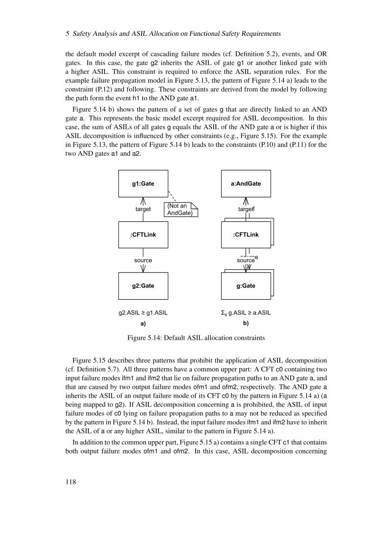
5 Safety Analysis and ASIL Allocation on Functional Safety Requirements
the default model excerpt of cascading failure modes (cf. Definition 5.2), events, and ORgates. In this case, the gate g2 inherits the ASIL of gate g1 or another linked gate witha higher ASIL. This constraint is required to enforce the ASIL separation rules. For theexample failure propagation model in Figure 5.13, the pattern of Figure 5.14 a) leads to theconstraint (P.12) and following. These constraints are derived from the model by followingthe path form the event h1 to the AND gate a1.
Figure 5.14 b) shows the pattern of a set of gates g that are directly linked to an ANDgate a. This represents the basic model excerpt required for ASIL decomposition. In thiscase, the sum of ASILs of all gates g equals the ASIL of the AND gate a or is higher if thisASIL decomposition is influenced by other constraints (e.g., Figure 5.15). For the examplein Figure 5.13, the pattern of Figure 5.14 b) leads to the constraints (P.10) and (P.11) for thetwo AND gates a1 and a2.
g2:Gate
:CFTLink
source
g1:Gate
g2:Gate
{Not an AndGate}
:CFTLink
target
source
a)
a:AndGate
g:Gate
:CFTLink
source
b)
targettarget
g2.ASIL ≥ g1.ASIL Σg g.ASIL ≥ a.ASIL
Figure 5.14: Default ASIL allocation constraints
Figure 5.15 describes three patterns that prohibit the application of ASIL decomposition(cf. Definition 5.7). All three patterns have a common upper part: A CFT c0 containing twoinput failure modes ifm1 and ifm2 that lie on failure propagation paths to an AND gate a, andthat are caused by two output failure modes ofm1 and ofm2, respectively. The AND gate ainherits the ASIL of an output failure mode of its CFT c0 by the pattern in Figure 5.14 a) (abeing mapped to g2). If ASIL decomposition concerning a is prohibited, the ASIL of inputfailure modes of c0 lying on failure propagation paths to a may not be reduced as specifiedby the pattern in Figure 5.14 b). Instead, the input failure modes ifm1 and ifm2 have to inheritthe ASIL of a or any higher ASIL, similar to the pattern in Figure 5.14 a).
In addition to the common upper part, Figure 5.15 a) contains a single CFT c1 that containsboth output failure modes ofm1 and ofm2. In this case, ASIL decomposition concerning
118

5.3 ASIL Allocation on the Function Hierarchy
pathTo pathTo
a:AndGate
c1:CFT contains
contains
c2:CFT
pathTo
contains
c0:CFT contains
contains
contains
pathToFirstpathToFirst
ifm2:InputFailureMode
ifm1:InputFailureMode
ofm2:OutputFailureMode
ofm3:OutputFailureMode
ofm1:OutputFailureMode
c1:CFT
contains
c2:CFT
pathTo
contains
pathToFirstpathToFirst
ofm2:OutputFailureMode
ofm1:OutputFailureMode
c1:CFT contains
contains
pathToFirstpathToFirst
ofm2:OutputFailureMode
ofm1:OutputFailureMode
a)
b)
c)
ifm1.ASIL ≥ a.ASILifm2.ASIL ≥ a.ASIL
Figure 5.15: Prohibited ASIL decomposition constraints
119
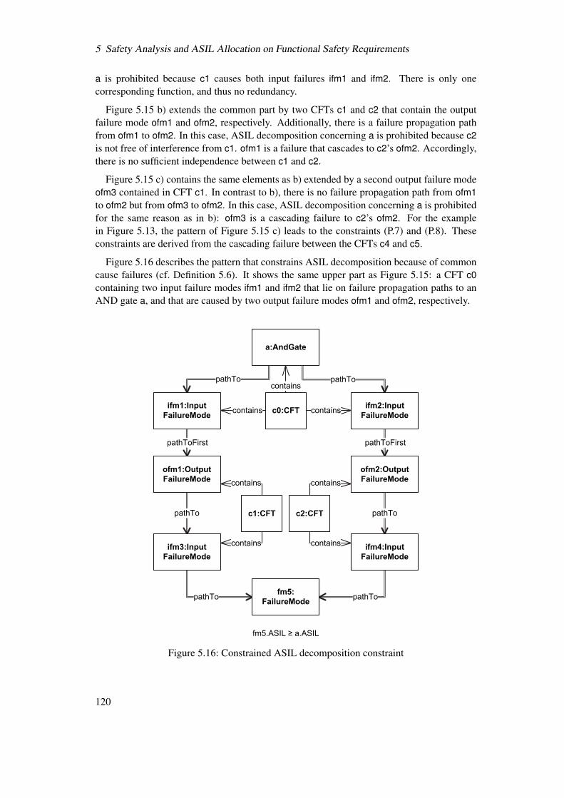
5 Safety Analysis and ASIL Allocation on Functional Safety Requirements
a is prohibited because c1 causes both input failures ifm1 and ifm2. There is only onecorresponding function, and thus no redundancy.
Figure 5.15 b) extends the common part by two CFTs c1 and c2 that contain the outputfailure mode ofm1 and ofm2, respectively. Additionally, there is a failure propagation pathfrom ofm1 to ofm2. In this case, ASIL decomposition concerning a is prohibited because c2is not free of interference from c1. ofm1 is a failure that cascades to c2’s ofm2. Accordingly,there is no sufficient independence between c1 and c2.
Figure 5.15 c) contains the same elements as b) extended by a second output failure modeofm3 contained in CFT c1. In contrast to b), there is no failure propagation path from ofm1to ofm2 but from ofm3 to ofm2. In this case, ASIL decomposition concerning a is prohibitedfor the same reason as in b): ofm3 is a cascading failure to c2’s ofm2. For the examplein Figure 5.13, the pattern of Figure 5.15 c) leads to the constraints (P.7) and (P.8). Theseconstraints are derived from the cascading failure between the CFTs c4 and c5.
Figure 5.16 describes the pattern that constrains ASIL decomposition because of commoncause failures (cf. Definition 5.6). It shows the same upper part as Figure 5.15: a CFT c0containing two input failure modes ifm1 and ifm2 that lie on failure propagation paths to anAND gate a, and that are caused by two output failure modes ofm1 and ofm2, respectively.
pathTo pathTo
a:AndGate
c0:CFT contains
contains
contains
c1:CFT
contains
contains
pathToFirstpathToFirst
pathTo pathToc2:CFT
contains
contains
ifm2:InputFailureMode
ifm1:InputFailureMode
ofm2:OutputFailureMode
ofm1:OutputFailureMode
fm5.ASIL ≥ a.ASIL
pathTo pathTofm5:
FailureMode
ifm4:InputFailureMode
ifm3:InputFailureMode
Figure 5.16: Constrained ASIL decomposition constraint
120

5.3 ASIL Allocation on the Function Hierarchy
In addition, ofm1 is contained in a CFT c1 that also contains an input failure mode ifm3lying on a failure propagation path to ofm1. Similarly, ofm2 is contained in a CFT c2 withan input failure mode ifm4. Furthermore, there is a failure mode fm5 that lies on a failurepropagation path to both ifm3 and ifm4. In this case, the CFTs c1 and c2 are free frominterference but ifm3 and ifm4 are common cause failures (both caused by fm5). Hence, c1and c2 are only sufficiently independent if fm5 is allocated with the same ASIL as a or ahigher ASIL. If this constraint is fulfilled, ASIL decomposition concerning a is allowed. Forthe example in Figure 5.13, the pattern of Figure 5.16 leads to the constraint (P.9). It isderived from the failure i3 that is a common cause for the CFTs c3 and c4 concerning a1.
Algorithm 5.4 sketches how ILP constraints are derived from a failure propagation modelbased on the patterns from Figures 5.14 to 5.16. Combined with the ASIL minimizationobjective (P.1) the ILP can be passed to an ILP solver. Afterward, the resulting solution’svariables contain the ASILs to be allocated to gates and CFTs of the failure propagationmodel.
5.3.2 Allocating ASILs to Functions and Functional SafetyRequirements
ASILs are assigned to hazards to categorize their safety-criticality. Functional safetyrequirements are specified to prevent or mitigate hazards and inherit the addressed hazard’sASIL. Functions are used to decompose the required functionality and group the functional(safety) requirements. During decomposition and refinement of functions and requirements,the corresponding ASILs can be lowered for sub-functions and -requirements by applyingASIL tailoring measures. The set of applied, valid ASIL tailoring measures dictates theallocation of ASILs to functions and functional safety requirements.
Figure 5.17 shows all model elements that can be assigned with an ASIL and their ASILallocation constraints. Each Hazard’s safety-criticality is specified by an ASIL. The failurepropagation model consists of CFTs that represent the failure propagation of the functionhierarchy. The ASIL of a hazard propagates along the paths of CFT Gates that are involvedin the occurrence of the hazard and is reduced where valid ASIL tailoring is applied.This allocation of ASILs to gates and CFTs follows the rules and constraints described inSection 5.3.1. As each CFT represents the failure propagation of a Function, each functioninherits the ASIL of its corresponding CFT. Safety requirements on functions are specifiedusing MSDs (cf. Chapter 4). The failure propagation of each function is derived from itsMSDs as described in Section 5.2.3. A failure in the fulfillment of an MSD requirementleads to an output failure mode of the corresponding function’s CFT. Therefore, each MSDinherits the maximum ASIL of all output failure modes that were derived from it.
Figure 5.18 shows an example result of ASIL allocation to MSD requirements. ASILsare annotated on model elements using the stereotype Safety Classified Element from thesafety profile (cf. Figure 3.5 on page 45). The diagram in the top shows an excerpt of afailure propagation model after a valid ASIL allocation was calculated by an ILP solver(cf. Section 5.3.1.2). There are two Hazard CFTs with events representing the ASIL Dhazard Hard Braking Omission and the ASIL B hazard Emcy Brake Warning Omssion fromFigure 3.4 on page 44. There is a failure propagation path from the sub-CFT Make DecisionCFT to each Hazard CFT (illustrated by a dashed CFT link). The ASIL of both hazardspropagates down to the two output failure modes of the CFT and on to an AND gate where
121

5 Safety Analysis and ASIL Allocation on Functional Safety Requirements
Algorithm 5.4 Collecting ASIL Allocation Constraints
1: for all Events e typed by a Hazard do . Fixed ASIL constraints from Hazards2: Add constraint: e.ASIL = <ASIL value of Hazard>3: end for4: for all FailureModes f not contained in a HazardCFT do . CFT constraints5: c := CFT containing f6: Add constraint: c.ASIL ≥ f .ASIL7: end for8: for all Gates g0 do . Default ASIL constraints9: if g0 is an AndGate then
10: A := all Gates directly succeeding g011: Add constraint:
∑g∈A g.ASIL ≥ g0.ASIL
12: else13: for all Gates g1 directly succeeding g0 do14: Add constraint: g1.ASIL ≥ g0.ASIL15: end for16: end if17: end for18: for all AndGates a do . Prohibited and constrained ASIL decomposition constraints19: c := CFT containing a20: I := All InputFailureModes contained in c and succeeding a21: for all pairs of InputFailureModes (i1, i2) in I × I with i1 6= i2 do22: o1 := First non-delegating OutputFailureMode succeeding i123: o2 := First non-delegating OutputFailureMode succeeding i224: if o1 or o2 does not exist then25: continue for loop . i1 or i2 is not caused by a function of the SuD26: end if27: c1 := CFT containing o128: c2 := CFT containing o229: if (c1 = c2) or (c1 contains an OutputFailureMode succeeding o2) or (c2 contains
an OutputFailureMode succeeding o1) then . Prohibited ASIL decomposition30: Add constraint: i1.ASIL ≥ a.ASIL31: Add constraint: i2.ASIL ≥ a.ASIL32: else33: J1 := All InputFailureModes contained in c1 succeeding o134: J2 := All InputFailureModes contained in c2 succeeding o235: for all pairs of InputFailureModes (j1, j2) in J1 × J2 with j1 6= j2 do36: if j1 and j2 are both succeeded by the same FailureMode f then .
Constrained ASIL decomposition37: Add constraint: f .ASIL ≥ a.ASIL38: end if39: end for40: end if41: end for42: end for
122

5.3 ASIL Allocation on the Function Hierarchy
ASIL DASIL D(D)ASIL C(D)ASIL CASIL C(C)ASIL B(D)ASIL B(C)ASIL BASIL B(B)ASIL A(D)ASIL A(C)ASIL A(B)ASIL AASIL A(A)QM(D)QM(C)QM(B)QM(A)QM
«Enumeration»ASILKind
CFT
Gate
Function
MSD
{ASIL = (cf. constraints in previous section)}
{ASIL = max. ASIL of contained FailureModes}
{ASIL = ASIL of corresponding CFT}
{ASIL = max. ASILof derived OutputFailureModes}
ASIL: ASILKind
Hazard
ASIL: ASILKind
SafetyClassifiedElement
Figure 5.17: Meta model elements considered by ASIL allocation and their ASIL relations
valid ASIL decomposition was applied. Hence, the two input failure mode’s ASILs werereduced to ASIL B(D). The CFT inherits ASIL D as maximum ASIL of its failure modes.Consequently the function Make Decision whose failure propagation is represented by theCFT inherits ASIL D as well.
The failure propagation model was derived from the MSDs shown in the bottomof the figure. The two Brake Requirements require the sending of the informationactivateEmergencyBraking and are traced to the corresponding omission output failure modeof Make Decision CFT. The two Warn Requirements require the sending of the informationsendEmcyBrakeWarning and are traced to the other omission output failure mode. Thetwo sketched Pre Requirements require the sending of the information needed by the otherrequirements and are traced to corresponding omission output failure modes that lead to theinput failure modes of the CFT shown in the top diagram. The CFTs containing those outputfailure modes are not shown in the figure. Each MSD inherits the ASIL of the output failuremode that was derived from it.
5.3.3 Application to other Safety-Critical Domains
Different domains have different safety standards (cf. Section 2.3) but they all have SILs toclassify the safety-criticality of hazards. The SIL of a hazard classifies its safety-criticalityby the risk of its occurrence and is determined during hazard analysis and risk assessment(cf. Section 2.2). The risk of a hazard is defined as the combination of its probability ofoccurrence and the severity if it occurs (Risk = Probability × Severity). A hazard occursif one or more failures of a system’s functions occur. Hence, the probability of hazardoccurrence is dependent on the probability of function failures. If a hazard h is caused bya single failure f , the hazard probability Ph is equal to the failure probability Pf , and the
123
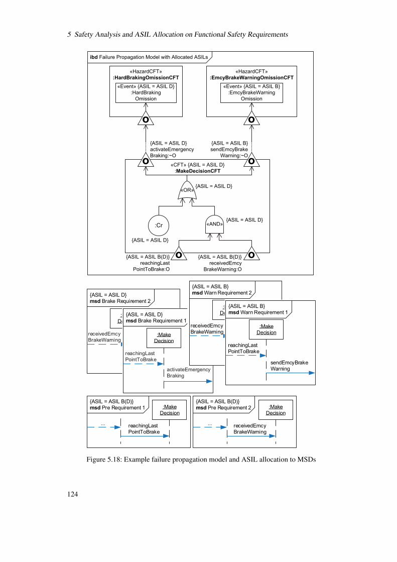
5 Safety Analysis and ASIL Allocation on Functional Safety Requirements
«CFT» {ASIL = ASIL D}:MakeDecisionCFT
o
:Cr
«OR»
oo
«AND»
o
«HazardCFT»:HardBrakingOmissionCFT
«Event» {ASIL = ASIL D}:HardBraking
Omission
o
«HazardCFT»:EmcyBrakeWarningOmissionCFT
«Event» {ASIL = ASIL B}:EmcyBrakeWarning
Omission
o
{ASIL = ASIL B(D)}reachingLast
PointToBrake:O
{ASIL = ASIL D}msd Brake Requirement 2
:MakeDecision
{ASIL = ASIL D}msd Brake Requirement 1
:MakeDecision
{ASIL = ASIL B}msd Warn Requirement 2
sendEmcyBrakeWarning
receivedEmcyBrakeWarning
:MakeDecision
{ASIL = ASIL B}msd Warn Requirement 1
sendEmcyBrakeWarning
reachingLastPointToBrake
:MakeDecision
{ASIL = ASIL B(D)}msd Pre Requirement 1
reachingLastPointToBrake
...
:MakeDecision
{ASIL = ASIL B}sendEmcyBrake
Warning:~O
{ASIL = ASIL D}
{ASIL = ASIL D}
{ASIL = ASIL D}
{ASIL = ASIL B(D)}receivedEmcy
BrakeWarning:O
{ASIL = ASIL D}activateEmergencyBraking:~O
{ASIL = ASIL B(D)}msd Pre Requirement 2
receivedEmcyBrakeWarning
...
:MakeDecision
ibd Failure Propagation Model with Allocated ASILs
Figure 5.18: Example failure propagation model and ASIL allocation to MSDs
124

5.3 ASIL Allocation on the Function Hierarchy
severity of that failure f is equal to the severity of the caused hazard h. Thus, the functioncausing that failure has the same risk as h and inherits its SIL.
In addition to that simple rule, in the automotive domain, ISO 26262 explicitly definesrules for SIL tailoring (cf. Section 2.5). The argument behind the ASIL tailoring ruleSeparation is that if a function f1 cannot cause a more critical function f2 to fail, it doesnot contribute to f2’s probability of failure, i.e., risk. Thus, f1 has a lower risk and may beassigned with a lower ASIL than f2 as specified in Definition 5.4.
The argument behind the ASIL tailoring rule Decomposition is as follows: If a hazard honly occurs if two failures f1 and f2 occur simultaneously, the hazard probability Ph is equalto the probability of both failures occurring simultaneously Pf1f2 . If the two failures arecaused by independent functions (such that Pf1f2 = Pf1 × Pf2), the two functions share therisk of h. In this case, the risk of h (its ASIL) may be arbitrarily distributed among the twofunctions as specified in Definition 5.7 (Ph = Pf1 × Pf2 ⇒ sf1 + sf2 = sh).
Not all safety standards provide explicit SIL tailoring rules. We claim that the reasoningbehind ASIL tailoring can be adopted for other domains. Separation is applicable to anydomain: If a function cannot cause a hazard, there is no reason for it to be developed to thedegree of rigor required for that hazard’s risk. Decomposition rules need to be individuallydefined and their validity argued if the domain standard provides no explicit rules.
In aerospace, ARP4754A specifies the concept of DAL decomposition [SAE10]. Similarlyto the ASIL, the DAL (Development Assurance Level) represents the required degree of rigorduring development of a system. It is also categorized into five values. The values range fromDAL A (highest) to DAL E (lowest). The DAL decomposition rules can be summarized asfollows [RPS+17]:• Option 1: One of the functions that are part of a decomposition concerning the same
failure f must keep the DAL of f , all other functions may be assigned with a DAL upto two levels lower than f ’s DAL.• Option 2: Two of the functions that are part of a decomposition concerning the same
failure f are assigned with a DAL one level lower than f ’s DAL, all other functionsmay be assigned with a DAL up to two levels lower than f ’s DAL.
DEFINITION 5.8 (DAL DECOMPOSITION)The sum of DALs of all CFTs that are part of a decomposition concerning an output failuremode o3 must be greater or equal to the number of involved CFTs D times the DAL that istwo levels lower than o3’s DAL so3 plus 2. The DAL of each of the involved CFTs D mustbe greater or equal to the DAL that is two levels lower than o3’s DAL so3 .
∑c∈D
sc ≥ |D|(so3 − 2) + 2 ∀ c3 ∈ C, o3 ∈ Oc3 , D = {c ∈ C\{c3} | o3 ∈ Decompc,c3}
sc ≥ so3 − 2 ∀ c ∈ D
To find valid DAL allocations to CFTs, safety classified elements must be allocated withDAL A to DAL E instead of ASIL D to QM. The ILP constraints remain the same as forASIL allocation, except the default constraint for AND gates (cf. Figure 5.14 b)). It has tobe exchanged with the following two constraints:
125

5 Safety Analysis and ASIL Allocation on Functional Safety Requirements
∑g∈D
g.DAL ≥ |D|(a.DAL− 2) + 2 with D = {g ∈ G | a pathToFirst g}
g.DAL ≥ a.DAL− 2 ∀ g ∈ D
From the definitions of ASIL decomposition and DAL decomposition one can see thatthere is a lower risk tolerance in the aerospace domain than in the automotive domain. InASIL decomposition, the decomposed function SILs have to add up to the original SIL.Even in the extreme case of ASIL D decomposition, one function may be considered non-safety-critical (QM(D)). In DAL decomposition, the decomposed function SILs have to addup to more than the original SIL, and no function may have a SIL lower than two levels belowthe original SIL.
The automated ASIL allocation presented in this chapter can be applied to both domainstandards. Hence, we claim that the (A)SIL tailoring process as a whole is applicable toembedded systems domains and the development of safety-critical cyber-physical systems.
5.4 Assumptions & Limitations
AssumptionsFor the derivation of the failure propagation model from requirements, we assume that allrequirement MSDs are instances of the requirement patterns of Section 4.4.2.
LimitationsWe use CFTs for the failure propagation model that are based on traditional fault trees andinherit their limitations (cf. [Int03]): Traditional fault trees are not considered applicable forfailures that are dependent on (1) the current state of the system (e.g., initialization, running,degraded, diagnosis), or (2) the order or timing of events. We mitigate these shortcomings byour use of MSDs: (1) ASIL tailoring requires the analysis of cascading and common causefailures (cf. Section 5.3.1.1) that exist in any state of the system. MSD specifications can begrouped by use cases that can represent different system states. Hence, we can generate afailure propagation model for each system state and compare their ASIL allocation resultsto find a valid solution for all system states. (2) MSDs support specifying and analyzing theorder and timing of events (cf. Section 2.7). As we need to consider any system state forASIL tailoring, we generate omission and commission failure modes if there is at least oneorder of events leading to such a failure. Furthermore, we use failure types for early and latetiming failures that can be derived from timed MSDs.
The current implementation for generating CFTs does not consider any MSD conditionsother than hot false conditions, no negative fragments, and no message parameters. Hence,failure modes typed by timing or value failure types are not generated.
The ILP we use for ASIL allocation calculates only one optimal allocation result althoughthere may be more than one optimal result that the safety manager could choose from (cf.conclusion in Section 5.3.1.1). However, one could use additional constraints to specify fixedASILs for certain functions that might be required due to reuse of legacy components witha specific ASIL or project cost constraints. Moreover, instead of an ILP solver, we coulduse meta heuristics that are more scalable for bigger failure propagation models. However,
126

5.5 Related Work
the implementation that we use for deriving allocation constraints is independent from anyconcrete solver, such that we could use different ILP solver implementations and also metaheuristics.
5.5 Related Work
We divide the work related to our method of safety analysis and ASIL allocation intotwo categories: work related to deriving failure propagation models from requirements(Section 5.5.1), and to allocating ASILs to functions (Section 5.5.2).
5.5.1 Generating Failure Propagation Models
HiP-HOPS is a failure propagation analysis solution that generates fault trees fromcomponent-based architectures [PM99]. The fault trees are generated from the structure ofthe components and their connections. Each component has to be annotated with its internalfailure specification. HiP-HOPS does not distinguish different failure types.
McKelvin et al. present an approach that derives fault trees from software deployments toECUs [MEP+05]. The purpose is to check for valid redundancy of ECUs. The software isspecified in their own language called Fault Tolerant Data Flow. A fault tree is derived fromthe SW/HW deployment model. The approach supports only the omission failure type.
Lauer et al. derive fault trees from software architectures and their deployment to ECUs[LGP11]. Their objective is to ease the comparison of different architecture alternatives.Behavior is specified by UML activities that are allocated to software components.Additionally, they define a UML profile to specify failures of components. The fault treesare derived from component failures and control flow of activities. The generated fault treesdo not distinguish different failure types.
Mader et al. generate fault trees and FMEA tables from an EAST-ADL model [MAL+11].They aim at safety analysis to show how safety goals can be violated by failures of themodeled embedded system. For that, an error model is specified for each system component.The fault trees and FMEA tables are derived from that error models. The error model doesnot differentiate between different types of failures.
Priesterjahn et al. derive failure propagation models from software behavior specificationswith the objective to analyze the timing of failure propagations [PHS13]. The behavior isspecified by timed automata. The failure propagation model is specified as timed petri net thatis derived from the state transitions and their timing conditions. Consequently, the approachfocuses on timing failures.
All mentioned approaches focus on software and hardware architectures, whereas wetarget requirements specifications in this thesis. Furthermore, all approaches except [PHS13]require the manual specification of failures and merely connect those local failure conditionsto global failure propagation models (i.e., fault trees) for the overall system. In this thesis,failures and failure propagations are completely generated from requirements specified asMSDs.
127

5 Safety Analysis and ASIL Allocation on Functional Safety Requirements
5.5.2 ASIL Allocation
Safar developed an approach for ASIL calculation on fault trees [Saf17]. The ASIL valuesare allocated to the failure modes of the fault trees. The fault tree structure and the ASILdecomposition rules are specified in a textual syntax for Satisfiability Modulo Theories. TheASIL allocation result is not transfered to a system or requirements model.
Mader et al. present an ASIL allocation approach for EAST-ADL models [MAL+12]. Theapproach uses traditional fault trees, one for each hazard of the system. Allocation constraintsare specified over minimal cut sets of the fault trees. One optimal ASIL allocation to systemcomponents is calculated by an ILP solver that respects a safety manager’s ASIL preferencesfor certain components. The approach does not use a complete failure propagation model (allfailure modes of all fault trees) for ASIL allocation but only allocates ASILs to components.Thus, the safety manager cannot see ASIL propagation paths that would support identifyingand deciding on system changes to gain a better (e.g., cheaper) ASIL allocation result.
Dhouibi et al. allocate ASILs to EAST-ADL elements based on minimal cut sets of faulttrees [DPS+14]. They use a system of linear equations to calculate all possible ASILallocations to the elements (not to failure modes). The identification of an optimal allocationis left to the safety manager.
Papadopoulos et al. also developed an approach for ASIL allocation to EAST-ADL models[PLB+10]. It uses HiP-HOPS [PM99] and presents all valid and optimal permutations ofASIL allocations (without safety manager preferences). In contrast to the approaches ofMader et al. and Dhouibi et al., ASILs are not allocated to components but to their failuremodes. The approach was improved by Azevedo et al. by using a meta heuristic to reducethe result permutations [APW+13]. Their allocation result is not necessarily optimal butthe computation is more scalable than solving an ILP. In 2014, they added the use of a costheuristic that specifies a cost value for each ASIL [APW+14]. This allows to express therelative savings of reducing from one ASIL to another.
The existing approaches for ASIL tailoring are applied in the phases of systemarchitectural design or software design. They calculate an ASIL allocation to subsystemsof a technical architecture with known failure propagation. They assume that ASIL tailoringmeasures (separation and decomposition) have already been applied – both on requirementsand architectural level – only the permutation of ASILs is left to decide. Furthermore,there is no ASIL allocation to requirements although ASIL decomposition is defined onrequirements (cf. Definition 2.26). Moreover, the approaches do not consider independence(cf. Definition 2.25) nor sufficient independence (cf. Definition 5.6). Instead, they leave theanalysis of dependent failures to the safety manager.
The ASIL allocation approach in this thesis, allocates ASILs to all failure modes of thefailure propagation model and to corresponding requirements. This supports the safetymanager in deciding on safety requirements changes for better ASIL allocation results.Furthermore, the rules for sufficient independence are considered by additional allocationconstraints.
128
5.6 Conclusion
5.6 Conclusion
This chapter describes the details about automated safety analysis and ASIL allocation onfunctional (safety) requirements as part of the ASIL tailoring process introduced in Chapter 3.Section 5.2 explains the used failure propagation meta model, the manual linkage of hazardsand top-level failures, and the automatic generation of CFTs. Section 5.3 specifies the ASILtailoring rules on CFTs for separation and decomposition, and how ASILs are allocated tofunctions and functional (safety) requirements by solving an ILP. Moreover, Section 5.3.3shows the applicability to more than the automotive domain.
The automatic derivation of a failure propagation model from functions and corresponding(safety) requirements supports early safety analysis by saving time and reducing manuallyintroduced errors. This is a step towards solving the safety requirements engineeringdilemma (cf. Challenge C2 in Section 1.2). Moreover, the automatic allocation of ASILsto functions and requirements that inherently checks for valid application of ASIL tailoringreduces manual effort and mistakes, and supports early planning of ASIL tailoring measuresand safety effort.
The following Chapter 6 adds an automatic documentation of safety arguments that linkhazards, safety analysis results, functions, and corresponding requirements to assure validASIL tailoring.
129


6
DOCUMENTING ASIL TAILORINGARGUMENTS
In Step 2.4 of the ASIL tailoring process (cf. Figure 6.1), together with the ASIL allocation,a safety argument is developed that provides assurance that all hazards are addressed byfunctional safety requirements and the ASIL tailoring is valid.
act ASIL Tailoring Process
Sys
tem
Des
igne
r,
Saf
ety
Man
ager
1. Analyze Environment and Hazards
2.3. GenerateFailure Propagation Model
for Function Hierarchy
2.4. CalculateASIL Allocation forFunction Hierarchy
2.2. Develop/Refine(Safety) Requirements
for Functions
3. Define System Architecture andAllocate Functions to System Elements
2.1. Develop/RefineFunction Hierarchy
CustomerRequirements
«datastore»System Architecture
Req
uire
men
ts E
ngin
eer,
Saf
ety
Man
ager
[functions sufficiently trivial and ASIL allocation reasonable]
«datastore»System
Requirements
FunctionHierarchy
FunctionHierarchy
FunctionHierarchy
Functional (Safety)Requirements
FSRs
Environment and Hazards with ASILs
System Elementswith ASILs
FailurePropagation
Model
FPM«datastore»Safety Case
Environment and Hazards with ASILsor Function Hierarchy [ASILs Tailored]
FunctionHierarchy
FunctionHierarchy
[ASILs Tailored]
Function Hierarchy[ASILs Tailored]
SafetyArgument
[else]
Figure 6.1: ASIL tailoring process with highlighted contents of Chapter 6
131

6 Documenting ASIL Tailoring Arguments
In this chapter, the details how this safety argument is derived from the function hierarchy,functional safety requirements, and failure propagation model is described.
This chapter is structured as follows. First, Section 6.1 summarizes the scientificcontributions of automated documentation of ASIL tailoring arguments. Section 6.2 explainsthe used safety argument language, and how the arguments are derived from an ASILallocated failure propagation model and related requirements. Section 6.3 lists assumptionsand limitations of the generation of safety arguments. In Section 6.4, related work isdiscussed. The final Section 6.5 concludes this chapter.
6.1 Contributions
The contributions of this chapter can be summarized as follows:
• A method and tool-support for safety case construction embedded in an ASIL tailoringprocess to foster model-based safety assessment.
• Support for traceability from safety arguments to related work products (i.e., hazards,safety requirements, functions, and safety evidence) in order to improve safety caseimpact analysis and maintenance.
• Automated safety case construction (including traceability) to reduce manual effortand errors.
• Automated derivation of validity arguments for applied ASIL tailorings.
• Support for building the safety case from the beginning of development (i.e., functionalsafety requirements analysis, cf. Challenge C3 in Section 1.2).
6.2 Safety Case Construction
There is no guarantee for 100% safety. Hence, the risk of hazards is determined, andmeasures are taken to reduce the risk as low as reasonably possible. Safety standards likeISO 26262 define SILs that categorize the risk of hazards into different levels. For each SILthey list state-of-practice measures that should be taken to prevent a hazard’s occurrence ormitigate its consequences.
As safety cannot be proven, confidence that the risk has been reduced as low as reasonablypossible, has to be provided by other means. The so-called safety case shall providethis confidence by compiling safety-relevant work products and linking them by a safetyargument (cf. Section 2.2). For each hazard, a safety argument shall link derived safetyrequirements with evidence for their fulfillment and contribution to hazard mitigation. Thisalso includes argumentation for the validity of applied ASIL tailorings. Thus, the safety caseprovides an overview of system safety, and is the central entry point for safety assessments.
In practice, safety arguments are usually written as free text documents [Kel98]. Freetext arguments can be ambiguous and usually require lots of cross-references. Thus, thesedocuments are difficult to analyze for completeness and validity of arguments. Especiallyin early development phases, requirements change regularly, and it is time-consuming anderror-prone to keep the free text arguments in sync and consistent with linked work products.
132

6.2 Safety Case Construction
Hence, safety arguments are specified late in the development process where changes are few[Kel98]. If mistakes in the arguments and missing safety measures are discovered late in thedevelopment, this causes expensive process iterations to integrate additional measures andupdate the safety case. The industry already identified the need to start building the safetycase from the beginning of the development process, but still misses supporting methods andtools [ZRH16].
To overcome the problems of safety argument ambiguity and structural complexity, the useof model-based languages is proposed by research [Kel98; CJL+08] and ISO 26262 [Int12b].Therefore, in this thesis, we chose the Goal Structuring Notation (GSN, cf. Section 2.8) tomodel safety arguments, as it is suggested in ISO 26262 [Int12b]. As part of the ASILtailoring process, we automatically generate a GSN safety argument that can be regeneratedwhenever an ASIL tailoring is applied on functional requirements, to support the constructionand maintenance of a safety case from the beginning of development.
This approach fosters an unambiguous overview of the safety-relevant work productsand navigation through the safety case by a graphical and model-based notation. Theautomatic generation avoids manually introduced errors and saves time because it can berepeated whenever changes occur. In addition, it simplifies impact analyses by automaticallymaintaining the traceability to other safety-related work products.
The following Section 6.2.1 describes how GSN safety arguments are specified in thisthesis. The details of safety argument generation are elaborated in Section 6.2.2.
6.2.1 Safety Arguments in Goal Structuring Notation Profile
The safety case links safety requirements with safety evidence by safety arguments. InISO 26262, safety requirements exist at different levels, starting from safety goals that arederived from hazards, over functional safety requirements that are refined into technicalsafety requirements down to hardware and software safety requirements (cf. Section 2.2).Safety evidence are safety analysis results, like FMEA tables and fault trees, that showabsence of failures or independence of subsystems. On technical, software, and hardwarelevel, also test results that verify safety requirement fulfillment, can be safety evidence.Safety arguments specify why given safety evidence contributes to the fulfillment of safetyrequirements (i.e., mitigation of hazards) and why applied ASIL tailoring measures are valid.
On functional level, the safety case contains the CFT failure propagation model as safetyevidence and GSN safety arguments that link the CFTs to functional safety requirements inform of MSDs (cf. Figure 3.2 on page 41).
In this thesis, we specify GSN safety arguments as UML models using a profile thatextends the SysML. This way, all work products of the ASIL tailoring process are basedon a single modeling language (the UML), which makes it easier to learn and understandtheir use. Furthermore, this enables the use of a single modeling environment. In addition,this supports the use of a common traceability concept, which is essential for safety casenavigation.
Figure 6.2 shows the elements of our GSN profile. All GSN nodes are represented byUML classes with specialized SysML Requirement stereotypes. The nodes are linked byspecialized UML Trace stereotypes. Figure 6.3 shows the application of the profile for anexample safety argument. It specifies how an ASIL D hazard H1 is mitigated by a Safety
133

6 Documenting ASIL Tailoring Arguments
Goal 1 and refining functional safety requirements (FSRs) with valid application of ASILDecomposition and ASIL Separation.
As explained in Section 2.8, the main nodes of GSN models are Goals, Strategies, andSolutions. Goals represent safety requirements or subparts of a safety argument that areclaimed to hold. In Figure 6.3, Safety Goal 1 and the several FSRs are examples of safetyrequirements specified as goals. The two Tailoring Goals are examples of argument subparts.They specify the goal of the two ASIL tailorings.
Strategies represent implications that form the line of argument. In adherence to theconcrete syntax of GSN, we denote strategies as parallelograms. In Figure 6.3, two appliedASIL tailorings are specified by the strategies ASIL Decomposition and ASIL Separation.
Solutions represent safety evidence. To adhere to the concrete syntax of GSN, we denotesolutions as circles. In Figure 6.3, the solution FEBEASCFT represents a failure propagationmodel that provides evidence for the connected claimed goals.
Goals and Strategies refer to subgoals, strategies, and solutions (evidence) thatsupport/refine their argument by SupportedBy traces. These links specify the line ofargument which is usually visualized in a tree layout from top to bottom. To adhere tothe concrete syntax of GSN, we denote this link type by a rounded arrow with a solid headand annotated with the SupportedBy stereotype.
Goals and Strategies can be marked as undeveloped by the respective stereotype’s attributeisUndeveloped. In original GSN syntax, this is denoted by a diamond below the element. Wedo not adopt this syntax to avoid confusion with UML aggregations. Undeveloped elementsneed further refinement by supporting goals and evidence. In Figure 6.3, the goals FSR1.1,FSR2.1, FSR1.2, FSR2.2, and FSR1.3 are marked as undeveloped because they are notlinked to further supporting goals (e.g., refining functional or technical safety requirements)or solutions.
Additionally, Goals and Strategies can be elaborated by Contexts, Justifications, andAssumptions. Akin to the concrete syntax of GSN, we denote these as rectangles withrounded corners. These elements are linked by InContextOf traces. We denote this linktype by a rounded arrow with a narrow, hollow head and annotated with the InContextOfstereotype, to adhere to the concrete syntax of GSN. In Figure 6.3, Safety Goal 1 is linkedto the context Hazard H1 to specify which hazard it addresses. The two strategies ASILDecomposition and ASIL Separation are linked to justifications that name the correspondingclauses of ISO 26262 that define and allow the two ASIL tailoring measures.
The example safety argument in Figure 6.3 is derived from the safety relevant workproducts shown in Figure 6.4. To support traceability from a GSN safety argument to thecorresponding work products, contexts, goals, and solutions are linked to hazards, functions,MSD requirements, and CFTs via UML traces. Table 6.1 lists the traces for the examplesafety argument in Figure 6.3. The context Hazard H1 is traced to the hazard H1 referred toby the event in the Hazard CFT HCFT. To be able to show the ASIL of traced work products,elements of the GSN safety argument are also applied with the SafetyClassifiedElementstereotype of the Safety Profile (cf. Figure 3.5 on page 45). Hence, the context Hazard H1inherits ASIL D from the Hazard CFT’s event. The Safety Goal 1 is traced to the omissionfailure of the information brake shall be prevented or mitigated because it directly leads tothe occurrence of the hazard H1. The goals FSR1 and FSR2 are traced to the MSDs withthe same name. These MSDs specify requirements on the top-level function FEBEAS whoseCFT is directly connected to the Hazard CFT. Similarly, the five supporting goals FSR1.1 to
134

6.2 Safety Case Construction
«profile» SysML4GSN
Text: String
«Stereotype»SysML::
Requirement
isUndeveloped: Boolean
«Stereotype»Goal
«Stereotype»UML::Trace
«Stereotype»GSNLink
«Stereotype»InContextOf
«Stereotype»SupportedBy
«Stereotype»Solution
«Stereotype»Context
«Stereotype»Reason
«Stereotype»Justification
«Stereotype»Assumption
isUndeveloped: Boolean
«Stereotype»Strategy
{C1: Client isGoal or Strategy}{C2: Supplier is Context or Reason}
{C3: Client is Goal or Strategy}{C4: Supplier is Goal, Strategy, or Solution}{C5: If client is Strategy, supplier is Goal}
Figure 6.2: UML Profile for the Goal Structuring Notation with constraints
FSR1.3 are traced to MSDs that specify requirements on the decomposed functions whoseCFTs lie on failure propagation paths to the omission failure of brake.
From the CFT model one can see that ASCFT and CWOVCFT are part of an ASILdecomposition concerning the brake failure. The corresponding MSDs FSR1.1 and FSR2.1specify redundant requirements with lowered ASIL. Hence, the Tailoring Goal 1 is traced tothose MSDs to argue the application of ASIL decomposition by the supporting strategy ASILDecomposition and the following goals on absence of cascading and common cause failuresFSR1.4 to FSR1.6. The solution FEBEASCFT traces to the CFT with the same name thatshows the absence of those failures between the functions AS and CWOV.
The CFT LCFT has no failure modes that lie on a failure propagation path to the omissionof brake. Hence, its corresponding function L is separate from the other functions on thesame hierarchy level. This application of ASIL separation is argued by the Tailoring Goal 2that is traced to L and its supporting ASIL Separation strategy and goal FSR1.7. The goalspecifies the required absence of cascading failures to the other functions and is supportedby the solution FEBEASCFT that references the CFT with that name as evidence.
135

6 Documenting ASIL Tailoring Arguments
«SupportedBy»
req Safety Argument
Text = “Prevent or mitigate brake:~O“ASIL = ASIL D
«Goal»Safety Goal 1
«Context»Hazard H1
ASIL = ASIL D
«Solution»FEBEASCFT
ASIL = ASIL D
«Goal»FSR1
ASIL = ASIL D
«Goal»FSR2
«SupportedBy»
«InContextOf»
«SupportedBy»
isUndev. = trueASIL = ASIL D
«Goal»FSR1.2
isUndev. = trueASIL = ASIL D
«Goal»FSR1.3
isUndev. = trueASIL = ASIL D
«Goal»FSR2.2
isUndev. = trueASIL = ASIL B(D)
«Goal»FSR1.1
isUndev. = trueASIL = ASIL B(D)
«Goal»FSR2.1
Text = “No CFfrom AS to CWOVconcerning brake:~O“ASIL = ASIL D
«Goal»FSR1.4
Text = “No CFfrom CWOV to ASconcering brake:~O“ASIL = ASIL D
«Goal»FSR1.5
Text = “No CCFof AS and CWOVconcerning brake:~O“ASIL = ASIL D
«Goal»FSR1.6
«SupportedBy»
«SupportedBy»
«SupportedBy»
«SupportedBy»
Text = “No CF from L to AS, CWOV, MD, or EPSconcerning brake:~O“ASIL = ASIL D
«Goal»FSR1.7
«SupportedBy»
«SupportedBy»
«Justification»ISO 26262-9:5
«Justification»ISO 26262-9:6
«InContextOf»
«InContextOf»
Text = “L is separated“ASIL = ASIL D
«Goal»Tailoring Goal 2
Text = “FSR1.1 and FSR2.1 are redundant“ASIL = ASIL D
«Goal»Tailoring Goal 1
«Strategy»ASIL Decomposition
Text = “Argument over sufficient independence“
«Strategy»ASIL Separation
Text = “Argument overfreedom from interference“
«SupportedBy»«SupportedBy»
«SupportedBy»
Figure 6.3: Example GSN safety argument for hazard H1
136

6.2 Safety Case Construction
«Fun
ctio
n»{A
SIL
D}
FE
BE
AS
«Fun
ctio
n»{A
SIL
B(D
)}A
S
«Fun
ctio
n»{A
SIL
B(D
)}C
WO
V
«Fun
ctio
n»{A
SIL
D}
EP
S
«Fun
ctio
n»{A
SIL
D}
MD
{AS
IL D
}m
sd F
SR
1
:FE
BE
AS
time
{AS
IL D
}m
sd F
SR
2
:FE
BE
AS
war
n
:AS re
ach
time
{AS
IL D
}m
sd
FS
R1.
2
:MD
act
rea
ch
{AS
IL D
}m
sd
FS
R1.
3
:EP
S brak
e
act
{AS
IL B
(D)}
ms
d F
SR
2.1
:CW
OV re
c
war
n
{AS
IL D
}m
sd F
SR
2.2
:MD
act
rec
«CF
T»
{AS
IL D
}:F
EB
EA
SC
FT
«CF
T»
{AS
IL D
}:M
DC
FT
o
oo
«CF
T»
{AS
IL D
}:E
PS
CF
T
«CF
T»
{AS
IL B
(D)}
:AS
CF
T«C
FT
» {A
SIL
B(D
)}:C
WO
VC
FT
o
oo
o
o
o o
«Haz
ardC
FT
» :H
CF
T
«Eve
nt»
{AS
IL D
} :H
1
o o
«Fun
ctio
n»{Q
M}
L
«CF
T»
{QM
}:L
CF
T
{AS
IL B
(D)}
msd
FS
R1.
1
{AS
IL B
(D)}
time:
O{A
SIL
B(D
)}w
arn
:O
{AS
IL B
(D)}
rec:
~O
{AS
IL B
(D)}
rea
ch:~
O
{AS
IL B
(D)}
rea
ch:O
{AS
IL B
(D)}
rec:
O
{AS
IL D
} ac
t:~O
{AS
IL D
} ac
t:O
o«t
race
»{A
SIL
D}
brak
e:~
O
«tra
ce»
Figu
re6.
4:E
xam
ple
func
tion
hier
arch
y,M
SDs,
and
CFT
137

6 Documenting ASIL Tailoring Arguments
Table 6.1: Traceability links of GSN safety argumentGSN Source Element Target Element Target Work Product«Context» Hazard H1 «Hazard» H1 Environment model«Goal» Safety Goal 1 «FailureMode» brake:∼O CFT model«Goal» FSR1 MSD FSR1 MSD specification«Goal» FSR2 MSD FSR2 MSD specification«Goal» FSR1.1 MSD FSR1.1 MSD specification«Goal» FSR2.1 MSD FSR2.1 MSD specification«Goal» FSR1.2 MSD FSR1.2 MSD specification«Goal» FSR2.2 MSD FSR2.2 MSD specification«Goal» FSR1.3 MSD FSR1.3 MSD specification«Goal» Tailoring Goal 1 MSDs FSR1.1 and FSR2.1 MSD specification«Goal» Tailoring Goal 2 «Function» L Function hierarchy«Solution» FEBEASCFT «CFT» FEBEASCFT CFT model
6.2.2 Generating Safety Arguments
Safety arguments for valid ASIL tailoring on functional safety requirements inherentlyhave a strong relation to the work products of the ASIL tailoring process presented inprevious chapters of this thesis. The example safety argument and its traceability tableshown in the previous section demonstrate this claim. Thus, we automatically derive safetyarguments from the failure propagation model, the function hierarchy, and the functionalsafety requirements to avoid manually introduced errors, save time, and maintain the safetycase in sync with functional safety requirements and applied ASIL tailoring measures.
The root node of a safety argument is always a hazard. The safety argument has to showhow the hazard is prevented or mitigated and why the taken measures are valid. Hence, foreach identified hazard, a safety argument has to be build up, that links the hazard with derivedsafety requirements and their refinement. We call this the default requirement hierarchy. If arequirement in that hierarchy is assigned with a lower ASIL than the hazard, ASIL tailoringwas applied. The validity of such a tailoring has to be argued within the safety argument andunderpinned by safety evidence (cf. ASIL tailoring rules in Section 5.3.1.1).
Algorithm 6.1 specifies the automatic derivation of GSN safety arguments from CFTfailure propagation models. It is based on the bachelor’s thesis of Trentinaglia [Tre18]. Thefailure propagation model contains a Hazard CFT for each hazard. Hence, a safety argumentis generated from each Hazard CFT. First, the root nodes of the argument are generated.Then, the default argument hierarchy is derived from the requirement hierarchy. Afterward,that argument hierarchy is adapted where ASIL separation or ASIL decomposition wasapplied on CFTs. These sub-steps are specified in the following Algorithms 6.2 to 6.5 andvisualized in Figures 6.5 to 6.8. In the figures, elements with gray background already existbefore application of the respective algorithm, and terms in angle brackets are placeholdersfor element names or ASIL values.
Figure 6.5 sketches the generation rule for the root node of a safety argument specified inAlgorithm 6.2. For each hazard <H>, a Hazard CFT exists in the failure propagation model.A context linked to a goal is generated for <H>. The context represents the hazard that is
138

6.2 Safety Case Construction
Algorithm 6.1 Generation of GSN safety arguments
1: for all HazardCFTs ch do2: GSNmodel G := GENERATESAFETYARGUMENTROOT(ch). Algo. 6.2 and Fig. 6.53: GENERATEDEFAULTARGUMENTHIERARCHY(G, ch) . Algo. 6.3 and Fig. 6.64: for all OutputFailureModes f on failure propagation paths to ch do5: GENERATESEPARATIONARGUMENT(G, f ) . Algo. 6.4 and Fig. 6.76: GENERATEDECOMPOSITIONARGUMENT(G, f ) . Algo. 6.5 and Fig. 6.87: end for8: end for
also represented by the event inside the Hazard CFT. It is annotated with the ASIL <ASILX>of the hazard (i.e., the event). The generated goal Safety Goal 1 represents the safety goalthat is derived from the hazard. It states the requirement that all failures <P> to <Q> of thetop-level function <F> have to be prevented or mitigated that lead to the hazard (i.e., lie ona failure propagation path to the Hazard CFT’s event). As the safety goal is directly derivedfrom the hazard, it is annotated with its ASIL <ASILX>.
«CFT»:<F>CFT
«HazardCFT»:<H>CFT
«Event»{<ASILX>}
:<H>
ibd HazardCFT FMs
<P> <Q>...
req Safety Argument
Text = “Prevent or mitigate <P>, …, and <Q>“ASIL = <ASILX>
«Goal»Safety Goal 1
«Context»Hazard <H>
ASIL = <ASILX>
«InContextOf»
Figure 6.5: GSN generation for hazard
Figure 6.6 sketches the generation rule for the default requirement hierarchy specifiedin Algorithm 6.3. The CFTs of the failure propagation model follow the structure of thefunction hierarchy. Concerning the CFTs in the figure, the functions F2 and F3 are childrenof the function F1. For each function of the function hierarchy, MSDs specify requirements.An MSD is traced by the failure modes of a function’s CFT that are caused by violation ofthe requirement. In the figure, MSD <R1> specifies a requirement on the function F1 andcauses the failure mode p∼.
The default requirement hierarchy in the GSN safety argument follows the failurepropagation paths starting from the hazard down to the deepest CFT hierarchy level. Startingfrom the hazard’s safety goal (e.g., Safety Goal 1) all MSDs that are traced by failure modeson the paths are mapped to a goal with the same name. Each of those goals is annotated with
139

6 Documenting ASIL Tailoring Arguments
Algorithm 6.2 GSN generation for hazard
1: function GENERATESAFETYARGUMENTROOT(HazardCFT ch)2: Create an empty GSNmodel G3: Add a context th for the hazard that the event of ch is typed by4: Set the ASIL of the context th to sx of the event/hazard5: Add a goal gs with ASIL sx of the event/hazard6: Let O be the set of OutputFailureModes directly linked to InputFailureModes of ch7: Set gs’s text to “Prevent or mitigate <List of all o ∈ O>”8: Connect the goal gs to the context th via an InContextOf link9: return G
10: end function
req Safety Argument
Text = “Prev. or mitigate p~“isUndeveloped = falseASIL = <ASILX>
«Goal»Safety Goal 1
isUndev. = falseASIL = <ASILX>
«Goal»<R1>
«SupportedBy»
isUndev. = trueASIL = <ASILX>
«Goal»<R2>
isUndev. = trueASIL = <ASILX>
«Goal»<R3>
«SupportedBy»
«CFT»:F1CFT
«CFT»:F3CFT
ibd CFT Hierarchy
{<ASILX>}msd <R1>
{<ASILX>}msd <R2>
{<ASILX>}msd <R3>
«trace»
«CFT»:F2CFT
«trace»
«trace»
{<ASILX>} p~
Figure 6.6: GSN generation for default requirement hierarchy
140

6.2 Safety Case Construction
the ASIL of the corresponding MSD. All goals referring to MSDs on the same function/CFThierarchy level, are on the same goal hierarchy level. In the figure, the MSDs <R2> and<R3> are on the same hierarchy level below MSD <R1> because F2 and F3 are children ofF1. Thus, the corresponding goals <R2> and <R3> are on the same hierarchy level belowgoal <R1>. The goal attribute isUndeveloped is set to false for each goal that has subgoalsand to true for each goal without subgoals (e.g., <R2> and <R3>).
Algorithm 6.3 GSN generation for default requirement hierarchy
1: function GENERATEDEFAULTARGUMENTHIERARCHY(GSNmodel G, HazardCFT h)2: for all InputFailureModes f of HazardCFT h do3: for all OutputFailureModes p directly linked to f do4: for all MSDs mr1 traced from p do5: Add a goal gr1 with the ASIL sx of the MSD mr1
6: Connect the existing safety goal gs to gr1 via a SupportedBy link7: Set isUndeveloped to false for goal gs8: Set isUndeveloped to true for goal gr19: end for
10: RECURSIVEGENDEFAULTHIERARCHY(p, p’s CFT)11: end for12: end for13: end function14: function RECURSIVEGENDEFAULTHIERARCHY(OutputFailureMode p, CFT c)15: for all OutputFailureModes o of direct subCFTs of c on paths to p do16: for all MSDs mr2 traced from o do17: Add a Goal gr2 with the ASIL sx of the MSD mr2
18: for all MSDs mr1 traced from p do19: if mr1 is a parent MSD of mr2 concerning p then20: Connect the goal gr1 derived from mr1 to gr2 via a SupportedBy link21: Set isUndeveloped to false for goal gr122: end if23: end for24: Set isUndeveloped to true for goal gr225: end for26: RECURSIVEGENDEFAULTHIERARCHY(o, o’s CFT)27: end for28: end function
Figure 6.7 sketches the generation rule for ASIL Separation arguments specified inAlgorithm 6.4. If a CFT <F3>CFT has a lower ASIL than another CFT <F2>CFT and ithas no output failure modes on a path to a higher ASIL output failure mode of <F2>CFT,ASIL separation was applied (cf. Definition 5.4 in Section 5.3.1.1). In the figure, the CFT<F3>CFT is assigned with an ASIL <ASILZ> that is lower than the ASIL <ASILX> of theCFT <F2>CFT. The failure mode q of CFT <F2>CFT is on a failure propagation path to thefailure mode <P> of <F1>CFT. The CFT <F3>CFT has no failure mode that is on a failurepropagation path to either q nor <P>. Hence, its ASIL <ASILZ> is lower than the ASILs
141

6 Documenting ASIL Tailoring Arguments
assigned to the two failure modes. The failure mode <P> originates from the requirement<R1>. <R2> refines this requirement and is the source of q .
req Separation Argument
ASIL = <ASILW>
«Goal»<R1>
ASIL = <ASILY>
«Goal»<R2>
«Solution»<F1>CFT
Text = “No CF from <F3> to <F2> concerning <P>“ASIL = <ASILW>
«Goal»FSR1.2
«SupportedBy»
«SupportedBy»
«SupportedBy»
«CFT»:<F1>CFT
«CFT»{<ASILX>}:<F2>CFT
«CFT»{<ASILZ>}:<F3>CFT
ibd Separated CFT
{<ASILY>}msd <R2>
«trace»
<ASILX> ≥ <ASILY> > <ASILZ><ASILW> ≥ <ASILY> > <ASILZ>
«Justification»ISO 26262-9:6
«InContextOf»
Text = “<F3> is separated“ASIL = <ASILW>
«Goal»Tailoring Goal 1
«Strategy»ASIL Separation
Text = “Argument overfreedom from interference“
«SupportedBy»
{<ASILY>} q~
{<ASILW>}msd <R1>
«trace»
{<ASILW>} <P>
Figure 6.7: GSN generation for ASIL separation
The right of Figure 6.7 shows the safety argument derived from the elements on the left.The goals <R1> and <R2> represent the requirement MSDs with the same name and aregenerated by the default requirement hierarchy rule (cf. Figure 6.6). All other elements aregenerated to argue valid separation of <F3> from <F2> concerning the sub-requirements of<R1>. The Tailoring Goal 1 claims that <F3> is separated from <F2> (i.e., <R2>). Thestrategy ASIL Separation specifies the application of ASIL tailoring in accordance withISO 26262-9, Clause 6 (cf. Justification ISO 26262-9:6). The supporting goal FSR1.2specifies the required claim that there are no cascading failures from the function <F3> to<F2> concerning the failure mode <P>. This claim is supported by the solution <F1>CFTreferring to the CFT that contains the two CFTs <F2>CFT and <F3>CFT.
142

6.2 Safety Case Construction
Algorithm 6.4 GSN generation for ASIL separation
1: function GENERATESEPARATIONARGUMENT(GSNmodel G, OutputFailureMode p)2: Let cf1 be the CFT containing p3: Let C be the set of all direct child CFTs of cf14: Let D ⊂ C be the set of CFTs with FailureModes on a path to p5: Let sw be the ASIL of p6: for all CFTs cf3 ∈ C\D with an ASIL lower than sw do7: Let f3 be the function traced by cf38: Add a goal gt with the text “f3 is separated” and ASIL sw9: for all MSDs mr1 traced from p do
10: Connect the existing goal gr1 representing mr1 to gt via a SupportedBy link11: end for12: Add a strategy y with name “ASIL Separation”13: Connect the goal gt to the strategy y via a SupportedBy link14: Add a justification j with name “ISO 26262-9:6”15: Connect the strategy y to the justification j via an InContextOf link16: Add a solution e referencing the CFT cf117: for all CFTs cf2 ∈ D with an ASIL higher than cf3 do18: Let f2 be the function traced by cf219: Add a goal g2 with ASIL sw20: Set g2’s text to “No CF from f3 to f2 concerning p”21: Connect the strategy y to the goal g2 via a SupportedBy link22: Connect the goal g2 to the solution e via a SupportedBy link23: end for24: end for25: end function
Figure 6.8 sketches the generation rule for ASIL Decomposition arguments specified inAlgorithm 6.5. If a CFT <F2>CFT contains an AND gate and at least one output failuremode s∼ of a directly preceding CFT <F3>CFT on a path to the AND gate has a lowerASIL than the output failure mode <P> of <F2>CFT on a path from the AND gate, ASILdecomposition was applied (cf. Definition 5.7 in Section 5.3.1.1). In the figure, the CFT<F2>CFT contains an AND gate on a failure propagation path to an output failure mode<P> with ASIL <ASILX>. In addition, two input failure modes s and t are on a path to theAND gate. As s has a lower ASIL <ASILV> than <P>, ASIL decomposition concering <P>has been identified as possible during ASIL allocation. The preceding output failure modes∼ must have an ASIL <ASILY> that is greater or equal to the ASIL of s because of thedefault ASIL allocation constraint (cf. Figure 5.14 a) on page 118). If ASIL decompositionconcerning <P> has been applied, <ASILY> is lower than the ASIL <ASILX> of <P>.
The requirements <R3> and <R4> are the reason for the AND gate in the CFT <F2>CFT.Each of them leads to the output failure mode <P> but caused by a different input failuremode. The requirements <R1> and <R2> lead to those input failure modes.
The right of Figure 6.8 shows the safety argument derived from the elements on the left.The goals <R1> to <R4> represent the requirement MSDs with the same name and aregenerated by the default requirement hierarchy rule (cf. Figure 6.6). All other elements
143

6 Documenting ASIL Tailoring Arguments
«SupportedBy»
«SupportedBy»
req Decomposition Argument «Goal»FSR1
ASIL = <ASILX>
«Goal»<R3>
«Solution»<F1>CFT
Text = “No CF from <F3> to <F4> concerning <P>“ASIL = <ASILX>
«Goal»FSR1.5
«SupportedBy»
Text = “No CF from <F4> to <F3> concerning <P>“ASIL = <ASILX>
«Goal»FSR1.6
Text = “No CCF of <F3> and <F4> concerning <P>“ASIL = <ASILX>
«Goal»FSR1.7
ASIL = <ASILX>
«Goal»<R4>
ASIL = <ASILY>
«Goal»<R1>
ASIL = <ASILZ>
«Goal»<R2>
«SupportedBy»
«CFT»:<F1>CFT
«CFT»:<F2>CFT
«CFT»:<F3>CFT
«CFT»:<F4>CFT
ibd Decomposition CFT
{<ASILX>}msd <R3>
«AND»
{<ASILX>}msd <R4>
{<ASILY>}msd <R1>
{<ASILZ>}msd <R2>
«trace»
«trace» «trace»
«trace»
«Justification»ISO 26262-9:5
«InContextOf»
Text = “<R1> and <R2> are redundant“ASIL = <ASILX>
«Goal»Tailoring Goal 1
«Strategy»ASIL Decomposition
Text = “Argument over sufficient independence“
«SupportedBy»
«SupportedBy»
{<ASILX>} <P>
{<ASILY>}s~
{<ASILZ>}t~
{<ASILW>}t
{<ASILV>}s
<ASILX> > <ASILY> ≥ <ASILV>
Figure 6.8: GSN generation for ASIL decomposition
are generated to argue valid decomposition concerning the output failure mode <P>. TheTailoring Goal 1 claims that <R1> and <R2> are redundant. The strategy ASIL Decompositionspecifies the application of ASIL tailoring in accordance with ISO 26262-9, Clause 5 (cf.Justification ISO 26262-9:5). The supporting goals FSR1.5 and FSR1.6 specify the requiredclaims that there are no cascading failures from the function <F3> to <F4> concerning thefailure mode <P>, and vice versa. The supporting goal FSR1.7 specifies the required claimthat there are no common cause failures of the functions <F3> and <F4> concerning thefailure mode <P>. These claims are supported by the solution <F1>CFT referring to the CFTthat contains the two CFTs <F3>CFT and <F4>CFT.
6.3 Assumptions & Limitations
The ASIL tailoring process presented in this thesis focuses on functional safety requirements.Hence, safety argument claims (i.e., GSN goals) only refer to safety goals and functionalsafety requirements, not to later technical, software, or hardware safety requirements (cf.
144
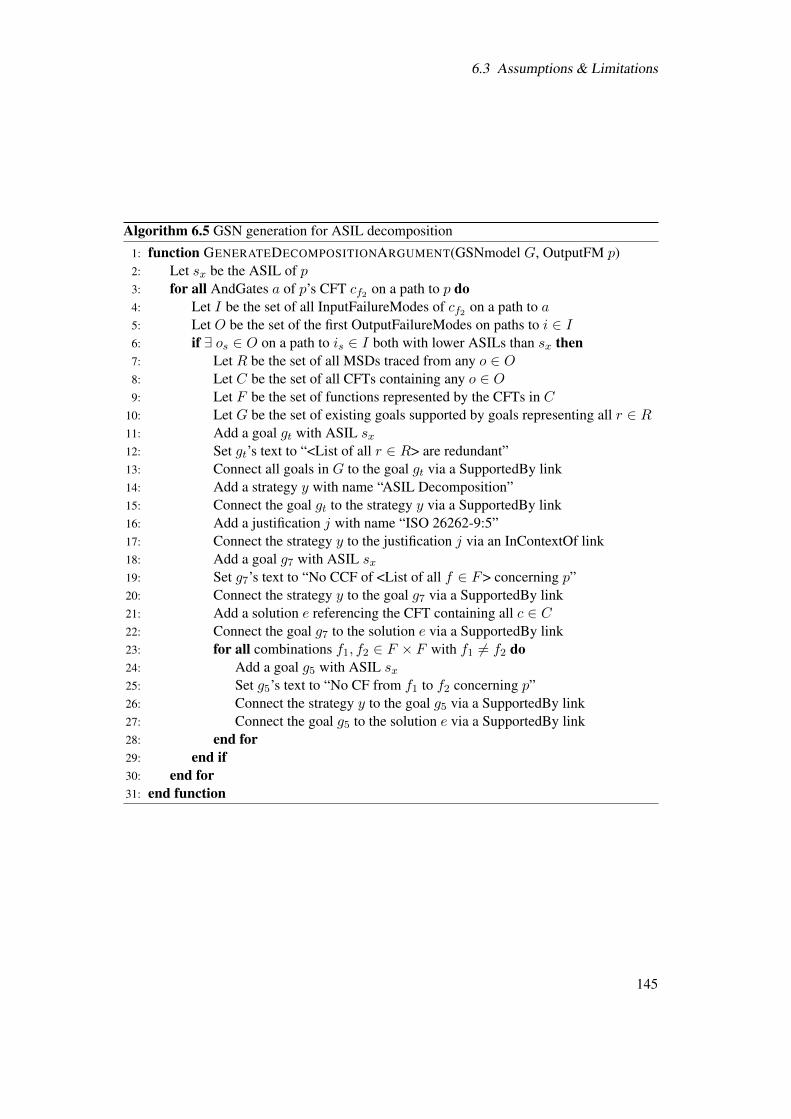
6.3 Assumptions & Limitations
Algorithm 6.5 GSN generation for ASIL decomposition
1: function GENERATEDECOMPOSITIONARGUMENT(GSNmodel G, OutputFM p)2: Let sx be the ASIL of p3: for all AndGates a of p’s CFT cf2 on a path to p do4: Let I be the set of all InputFailureModes of cf2 on a path to a5: Let O be the set of the first OutputFailureModes on paths to i ∈ I6: if ∃ os ∈ O on a path to is ∈ I both with lower ASILs than sx then7: Let R be the set of all MSDs traced from any o ∈ O8: Let C be the set of all CFTs containing any o ∈ O9: Let F be the set of functions represented by the CFTs in C
10: Let G be the set of existing goals supported by goals representing all r ∈ R11: Add a goal gt with ASIL sx12: Set gt’s text to “<List of all r ∈ R> are redundant”13: Connect all goals in G to the goal gt via a SupportedBy link14: Add a strategy y with name “ASIL Decomposition”15: Connect the goal gt to the strategy y via a SupportedBy link16: Add a justification j with name “ISO 26262-9:5”17: Connect the strategy y to the justification j via an InContextOf link18: Add a goal g7 with ASIL sx19: Set g7’s text to “No CCF of <List of all f ∈ F> concerning p”20: Connect the strategy y to the goal g7 via a SupportedBy link21: Add a solution e referencing the CFT containing all c ∈ C22: Connect the goal g7 to the solution e via a SupportedBy link23: for all combinations f1, f2 ∈ F × F with f1 6= f2 do24: Add a goal g5 with ASIL sx25: Set g5’s text to “No CF from f1 to f2 concerning p”26: Connect the strategy y to the goal g5 via a SupportedBy link27: Connect the goal g5 to the solution e via a SupportedBy link28: end for29: end if30: end for31: end function
145

6 Documenting ASIL Tailoring Arguments
Section 2.2). In line with that, safety evidence (i.e., GSN solutions) only refer to safetyanalysis results (i.e., CFTs) and not to evidence from later development phases like testresults. We assume that GSN goals referring to functional safety requirements that arenot further refined/supported by additional GSN elements (their attribute isUndevelopedis true), will be extended by GSN goals referring to technical safety requirements in laterdevelopment phases.
6.4 Related Work
We divide the work related to our method of documenting safety arguments into twocategories: work related to the used safety argument representation (Section 6.4.1), and togenerating safety arguments (Section 6.4.2).
6.4.1 Safety Argument Notations
The EAST-ADL is an architecture description language for automotive electronic systems[EAS13]. It is comprised of a variety of modeling aspects. In its dependability part, itincludes a safety argument notation of claims, warrants, and evidence that is also available asUML profile [EAS10]. In contrast to the UML profile used in this thesis, it does not containany constraints to restrict the language’s static semantics. Although the latests EAST-ADLversion defines the mentioned own safety argument notation, an earlier version used GSN(cf. [CJL+08]) as we do in this thesis.
Similarly to our approach, Beckers et al. define a UML profile for GSN including OCLconstraints for static semantics [BCF+14]. In contrast to our profile, theirs does not extendthe SyML, and thus, does not rely on the SysML requirement stereotype but instead definesits own requirement stereotype. Moreover, their profile extends GSN to distinguish differenttypes of goals. For instance, they specialize the stereotype “Goal” into “Safety Goal”and “Functional Safety Requirement”. We see this as a mixture of concerns betweenrequirements engineering and safety assurance. In this thesis, we use MSDs for specifyingsafety requirements and GSN for specifying safety assurance arguments. The goals in safetyarguments only link to MSD requirements for traceability. Furthermore, their profile isincomplete because it does not contain GSN solutions. These are essential to specify safetyargument evidence (e.g., safety analysis or test results).
6.4.2 Generating Safety Arguments
Kelly and McDermid extend the GSN language to be able to specify patterns of safetyarguments [KM97]. This language extension contains placeholders for variable element textsand multiplicities for edges. Kelly and McDermid provide a set of example patterns usingthe GSN extension but they do not define SIL tailoring argument patterns. The semantics ofthe extension are not formally defined. For instance, if a Supported-By link with multiplicityn is connected to a goal containing a placeholder, it is unclear whether the placeholder isinstantiated n times with the same value or whether it represents a list of n values. Hence,this GSN extension cannot be used to automatically generate safety arguments.
Denney and Pai present a formalization of Kelly and McDermid’s GSN extension forsafety argument patterns [DP13]. Based on the formalization they provide an algorithm
146

6.5 Conclusion
to automatically instantiate patterns. This algorithm requires as input a table of valuepopulations for a pattern’s placeholders to instantiate the pattern. The algorithm does not useexisting work products, like requirements specifications or safety analysis results, to derivethe placeholder values. Consequently, SIL tailoring arguments are not automatically derivedfrom other work products as we do in this thesis.
In [SPB16], Sorokos et al. generate SIL tailoring arguments for the aerospace domainbased on SIL allocations calculated via HiP-HOPS [APW+14]. However, they neitherpresent generation rules nor an algorithm for automatic derivation of the SIL tailoringarguments, they only show example results. In addition, they only generate arguments forSIL tailoring, and do not include the hierarchical safety argument structure following thesafety requirement hierarchy from the hazards down to applied SIL tailorings. Furthermore,they do not consider traceability from safety arguments to related work products for safetyimpact analysis. Eventually, their approach is not applied in early requirements engineeringbut works on system components instead of functions or functional safety requirements.
Retouniotis et al. extend the approach of Sorokos et al. by traceability to design modelsand related fault trees [RPS+17]. This approach still is only presented by example, sketchinga generation rule and the applying algorithm in a figure. They present a custom metamodel for GSN arguments and trace links to system components and fault trees. This metamodel is an extension of the meta model used by HiP-HOPS. Hence, their approach is notrelying on a standard modeling language like UML, and thus, is not easily integrated ina standard modeling environment. On the contrary, the approach presented in this thesissolely extends the UML and SysML by profiles, and thus, can be adopted in any UMLmodeling environment. Similarly to Sorokos et al., Retouniotis et al. still do not includethe hierarchical safety argument structure following the safety requirement hierarchy fromthe hazards down to applied SIL tailorings. Furthermore, the traceability is limited to systemdesign components and system level fault trees. They do not trace to functions, correspondingfailure propagation models, nor requirements. Hence, their approach is not applicable inearly requirements engineering, which is the focus of the approach presented in this thesis.
6.5 Conclusion
This chapter describes the details about automated derivation of safety arguments from workproducts of the ASIL tailoring process presented in Chapter 3. Section 6.2.1 describes howwe apply the model-based safety argument notation GSN, and its integration with the otherASIL tailoring process work products. Moreover, Section 6.2.2 describes the automaticgeneration of GSN safety arguments from ASIL allocated failure propagation models (cf.Chapter 5) and corresponding functions and functional safety requirements (cf. Chapter 4).
The use of GSN for documenting safety arguments and its integration with the relatedUML-based work products fosters model-based safety assessment in early developmentphases. The use of a common base language enables integration in a single modelingenvironment and improves safety case impact analysis and maintenance. The automaticgeneration of safety arguments saves time in safety case construction and reduces manuallyintroduced errors. Especially, the automatic generation also considers applied ASILtailorings and derives validity arguments conforming to standards like ISO 26262. All in
147

6 Documenting ASIL Tailoring Arguments
all, this approach supports time-saving construction of safety cases right from the beginningof development (cf. Challenge C3 in Section 1.2).
148

7
EVALUATION
This chapter presents the evaluation of the ASIL tailoring process. Section 7.1 gives anoverview of the prototype implementation of the automated process steps. In Section 7.2, theapplied case study is explained.
7.1 Prototype Implementation
To support and evaluate the concepts from Chapters 3 to 6, we implemented a softwareprototype. Figure 7.1 shows the components and dependencies of that implementation.Components that were implemented as part of this thesis are depicted with white background,and preexisting components that they depend on, have a gray background.
Eclipse Papyrus
QVTo
Eclipse RMF/ProR
UML4CFT Profile
SysML4GSN Profile
SysML4CONSENS Profile
ScenarioToolsModal Profile
Safety Profile
CFT Generation
ASIL Allocation
EloquentILP Transformation
LP Solve
GSN Generation
ReqPat2SysML/SysML2ReqPat
Xtext
Figure 7.1: Prototype components (white) and dependencies (gray)
149

7 Evaluation
All components were implemented as plug-ins for the IDE Eclipse1. All modelsare specified using the UML/SysML editor Eclipse Papyrus2. Hence, all required anddeveloped UML profiles are dependent on Papyrus. We use the Modal Profile provided byScenarioTools3 to specify MSDs and the SysML4CONSENS Profile for CONSENS modelelements (i.e., environment, function hierarchy, and system architecture; cf. Section 2.6). Wedefined the Safety Profile to specify hazards and safety classified elements (cf. Figure 3.5 onpage 45). The UML4CFT Profile is used to model CFTs and Hazard CFTs (cf. Figure 5.5 onpage 100). To specify GSN arguments, we defined the SysML4GSN Profile (cf. Figure 6.2on page 135). The use of the single modeling environment Papyrus allows to have all workproducts in one SysML model with a single traceability concept from GSN safety argumentsto CFT failure propagation and MSD requirements (cf. Figure 3.18 on page 59).
The CFT Generation described in Section 5.2.3 is realized as model-to-modeltransformation using QVTo4. Its implementation is based on student work from membersof the project group Aramid [BBB+16]. The ASIL Allocation as explained in Section 5.3also uses QVTo. The CFT model is transformed into an ILP model based on a meta modelprovided by Eloquent5. The Eloquent ILP Transformation transforms that ILP into input forthe ILP solver LP Solve6. Eloquent provides an interface to several ILP solvers and alsometa heuristics. Hence, the usage of LP Solve is only an example here. We can also switchto other solvers. The ILP solution provided by Eloquent is used to allocate ASILs to the CFTelements, functions, and MSDs.
The GSN Generation explained in Section 6.2.2 uses QVTo to derive safety argumentmodels from hazards, CFTs, and MSDs. Its implementation is based on the bachelor’s thesisof Roman Trentinaglia [Tre18].
To be able to also specify textual requirements on functions as described inSection 4.5 (e.g., requirements on absence of cascading and common cause failures),we integrate the function hierarchy model with textual requirements using our plug-in ReqPat [FH15]. It is integrated into the requirements editor Eclipse RMF/ProR7
and uses Xtext8 for the specification of textual requirement patterns. Our componentReqPat2SysML/SysML4ReqPat is an adaptation of the transformation described in [FH14]to use QVTo and the CONSENS function hierarchy.
Figure 7.2 shows the implemented ASIL tailoring transformation chain with input andoutput models. In Step 1 of the ASIL tailoring process, the CONSENS Environmentand Hazards are specified using Eclipse Papyrus, the SysML4CONSENS profile, andour safety profile. In Step 2.1, the CONSENS Function Hierarchy is specified with theSysML4CONSENS profile. In Step 2.2, the MSD Requirements are specified using theModal profile provided by ScenarioTools. In Step 2.3.1, the Hazard CFTs are specifiedusing our UML4CFT profile.
1www.eclipse.org2www.eclipse.org/papyrus3www.scenariotools.org4www.eclipse.org/mmt/qvto5www.github.com/upohl/eloquent6lpsolve.sourceforge.net7www.eclipse.org/rmf8www.eclipse.org/xtext
150

7.1 Prototype Implementation
CFT Generation
CONSENS Environmentand Hazards
CONSENSFunction Hierarchy MSD Requirements
CFT Failure Propagation Model
ASIL allocatedCFT Failure Propagation Model
GSN Safety Argument
ASIL Allocation
GSN Generation
ASIL allocatedCONSENS Function Hierarchy
ASIL allocatedMSD Requirements
act Transformation Chain with Inputs and Outputs
Step 1 Step 2.1 Step 2.2
Step 2.3.2
Steps 2.4.1/2
Step 2.4.3
HazardCFTs
Step 2.3.1
Figure 7.2: Chain of transformations with input and output models
These four models are input to the QVTo transformation CFT Generation that generates theCFT Failure Propagation Model using the UML4CFT profile in Step 2.3.2. In addition, theCFT Generation creates traceability links from generated CFT elements to the functions andMSDs that they originate from. The CFT model is used by the QVTo transformation ASILAllocation in Steps 2.4.1 and 2.4.2 to calculate and allocate ASILs using the Safety ClassifiedElement stereotype of our safety profile. The result is an ASIL allocated CFT FailurePropagation Model, an ASIL allocated CONSENS Function Hierarchy, and ASIL allocatedMSD Requirements. Finally, in Step 2.4.3, these ASIL allocated models and the hazardsfrom the CONSENS Environment and Hazards are used by the QVTo transformation GSNGeneration to derive the GSN Safety Argument using our SysML4GSN profile. Additionally,it connects safety argument elements via traceability links to hazards, functions, MSDrequirements, and CFTs.
151

7 Evaluation
7.2 Case Study
To evaluate the applicability and effectiveness of the ASIL tailoring process presented in thisthesis, we perform a case study. In that study, the manual and automated process steps areapplied on two cases. The automated steps are executed using the prototype implementationexplained in Section 7.1.
We perform the case study on the basis of the guidelines defined by Kitchenham et al.[KPP95] and Runeson and Höst [RH08]. Section 7.2.1 describes the posed evaluationquestions and the two cases. In Section 7.2.2, hypotheses on the evaluation results and criteriaof fulfillment are specified. In Section 7.2.3, the preparations of the case study are described.Section 7.2.4 contains the procedure of collecting and analyzing result data. Section 7.2.5concludes with the interpretation of the results, and Section 7.2.6 discusses threats to validity.
7.2.1 Context and Cases
The goal of this case study is to evaluate the applicability and effectiveness of the ASILtailoring process presented in this thesis. Therefore, we evaluate the evaluation questionslisted in Section 7.2.1.1. We perform the case study on two cases: a rear door systemthat automatically opens/closes and locks/unlocks a vehicle’s rear door (cf. Section 7.2.1.2),and the EBEAS assistance system for crash avoidance introduced in Section 1.1 (cf.Section 7.2.1.3)
7.2.1.1 Evaluation Questions
To evaluate the applicability and effectiveness of the ASIL tailoring process, we pose thefollowing evaluation questions:
Q1: Does the ASIL tailoring process work for realistic examples?Q2: Do the automated process steps produce correct results?Q3: Does the ASIL tailoring process reduce manual effort?
7.2.1.2 Case 1: Rear Door System
Case 1 is a rear door system (RDS) of a car. It automatically opens/closes and unlocks/locksthe car’s rear door. These actions can be triggered by the car’s remote key or by other ECUsof the car.
The rear door system is a realistic example because such systems are already part ofseries production vehicles. In fact, the case is based on a textual requirements specificationdocument of an automotive OEM that we also used in [Foc16].
The rear door system is a safety-critical ASIL B system because the rear door shall notopen while the car is moving, and the door shall be unlocked in case of an accident.
7.2.1.3 Case 2: EBEAS
Case 2 is the Emergency Braking and Evasion Assistance System (EBEAS) as introduced inSection 1.1 and used as running example throughout this thesis. It automatically decides to
152

7.2 Case Study
brake or evade in emergency situations based on coordination with the surrounding vehiclesvia Vehicle-to-Vehicle communication.
We consider the EBEAS a realistic example because of the following reasons. First,Autonomous Emergency Braking systems are part of series production vehicles already andconsidered by the Euro NCAP test for vehicle safety since 2014 [Eur14]. Second, examplesof Autonomous Emergency Steering systems have been presented by automotive supplierslike Continental [Tut10] and ZF [ZF 16]. Though, they have not yet made it into seriesproduction. Third, the combination of autonomous emergency braking and steering has beenprototyped in a research project [ISS08]. Fourth, the theoretic feasibility of combiningautonomous emergency braking and steering with Vehicle-to-Vehicle communication fordecision making has been investigated in [HFK+16]. In conclusion, we argue that systemslike the EBEAS are the consequent next step of advanced driver assistance systems towardscomplex cyber-physical systems.
The EBEAS is highly safety-critical (ASIL D), as it interferes with brakes and steering. Ifdrivers rely on the system, it may not fail to brake or evade when necessary.
7.2.2 Hypotheses
We set the following evaluation hypotheses for this case study. The hypotheses H1 and H2refer to evaluation question Q1, hypotheses H3 to H5 refer to evaluation question Q2, andhypotheses H6 to H9 refer to evaluation question Q3.
H1: The functional (safety) requirements for the two cases can be specified using MSDs asdescribed in Chapter 4.We rate this hypothesis as fulfilled if the requirements can be specified using solely theMSD patterns defined in Table 4.4 on page 85.
H2: The CFT Generation supports all MSD patterns defined in Chapter 4.We rate this hypothesis as fulfilled if each specified MSD pattern results in a CFTobeying the CFT generation rules defined in Section 5.2.3.
H3: The CFT Generation produces correct failure propagation models for the two cases.We rate this hypothesis as fulfilled if the generated CFTs obey the syntax and semanticsof CFTs as defined in Figure 5.3 on page 98, and the model content is as we expected.
H4: The ASIL Allocation produces valid results for the two cases.We rate this hypothesis as fulfilled if the calculated ASILs obey the ASIL tailoring rulesdefined in Section 5.3.1.1.
H5: The GSN Generation produces correct safety arguments for the two cases.We rate this hypothesis as fulfilled if the generated GSN models obey the syntax andsemantics of GSN as defined in Figure 6.2 on page 135, and the model content is as weexpected.
H6: The performance of the CFT Generation for the two cases is reasonable.We rate this hypothesis as fulfilled if the execution time of the CFT Generation is belowan hour for both cases.
153

7 Evaluation
H7: The performance of the ASIL Allocation for the two cases is reasonable.We rate this hypothesis as fulfilled if the execution time of the ASIL Allocation is belowan hour for both cases.
H8: The performance of the GSN Generation for the two cases is reasonable.We rate this hypothesis as fulfilled if the execution time of the GSN Generation is belowan hour for both cases.
H9: The effort saved by the automated process steps outweighs the effort required forspecifying MSD requirements.We rate this hypothesis as fulfilled if the number of generated model elements is greaterthan the number of specified MSD model elements.
7.2.3 Preparation of the Data Collection
In preparation for the case study, we set up an Eclipse installation that includes the prototypeimplementation and its dependencies (cf. Section 7.1). In that installation, we prepare aseparate project with an empty Papyrus SysML model for both cases. For the performancemeasurements we use a business laptop with an Intel Core i7-4800MQ (2.7 GHz) with 8 GBRAM. It runs 64 bit Windows 7 SP 1 with 32 bit Java 1.8. We use Eclipse Neon 3.
7.2.4 Data Collection Procedure
We perform the evaluation by going through the steps of the ASIL tailoring process asdescribed in Chapter 3 for both cases.
In Step 1, the environment of the case is specified as defined in the CONSENS systemsengineering method. Afterward, the model is extended by hazards with ASIL values asidentified in HARA. The hazards are caused by failures later specified in the CFT failurepropagation model. The resulting diagram shall look as sketched in Figure 3.4 on page 44.
In Step 2.1, the function hierarchy is specified as defined in the CONSENS method. Eachfunction is extended by ports and interfaces that are required for the message exchange inMSD requirements. The resulting diagram shall look as sketched in Figure 3.8 on page 47.
In Step 2.2, the functional (safety) requirements of the case are specified using the MSDpatterns from Section 4.4.2. For each informal requirement from the case’s source document,a fitting MSD pattern is chosen and instantiated in the requirements model. We documentthe chosen patterns and the number of requirements for which no fitting pattern is found toevaluate Hypothesis H1.
In Step 2.3, the CFT failure propagation model is automatically generated from theprevious work products using the prototype’s CFT Generation (cf. Figure 7.2). First, foreach hazard from Step 1, a Hazard CFT is manually specified that defines what failures ofthe top-level function lead to the occurrence of the hazard. Afterward, the internal failurepropagation of the function hierarchy is automatically generated and linked to the HazardCFTs.
We check each generated CFT model for correctness (cf. Hypothesis H3) using the modelvalidation of Papyrus. It allows to automatically check OCL constraints contained in UMLprofiles. To be able to use this feature, we translated the informal constrains shown inFigure 5.3 on page 98 into OCL constraints included in our UML4CFT profile (cf. Figure 5.5
154

7.2 Case Study
on page 100). In addition, we manually review each generated CFT model to check whetherthe CFT generation rules (cf. Figures 5.9 and 5.10 on page 105 ff.) were applied correctly.For completeness, separately from the two cases, we specify an instance of each MSD patternthat is not used in the two cases, generate a CFT, and apply the same correctness checks ason the two cases (to evaluate Hypothesis H2). Furthermore, for each case, we measure theexecution time of three runs of the CFT Generation and document the mean value (to evaluateHypothesis H6).
In Steps 2.4.1 and 2.4.2, the ASILs of failure modes, functions, and MSDs areautomatically calculated based on the CFT model using the prototype’s ASIL Allocation (cf.Figure 7.2). First, the ASILs of failure modes and CFTs are calculated, afterward, the ASILsof corresponding functions and MSDs are derived.
We check each calculated ASIL allocation for correctness (cf. Hypothesis H4) byreviewing whether the result obeys the ASIL tailoring rules defined on the CFT meta model(cf. Section 5.3.1.1) and in Figure 5.17 on page 123. Furthermore, for each case, we measurethe execution time of three runs of the ASIL Allocation and document the mean value (toevaluate Hypothesis H7).
In Step 2.4.3, GSN safety arguments that assure the validity of applied ASIL tailorings,are automatically generated from the previous work products using the prototype’s GSNGeneration (cf. Figure 7.2). For each hazard specified in Step 1, a separate GSN argument isgenerated.
We check each generated GSN argument for correctness (cf. Hypothesis H5) using themodel validation of Papyrus. To be able to use this feature, we translated the informalconstrains shown in the SysML4GSN profile in Figure 6.2 on page 135 into OCL constraints.In addition, we manually review each generated GSN argument to check its semanticcorrectness concerning the corresponding MSD requirements and the ASIL allocated CFTmodel. Furthermore, for each case, we measure the execution time of three runs of the GSNGeneration and document the mean value (to evaluate Hypothesis H8).
In Step 3, the system architecture of the case is specified as defined in the CONSENSsystems engineering method. This includes the allocation of the leaf functions of the functionhierarchy to elements of the architecture. The resulting diagram would look as sketched inFigure 3.17 on page 56. As this is a default step of the systems engineering method, and it isnot enhanced by the ASIL tailoring process, we do not apply this step in the case study.
In all steps of the ASIL tailoring process, we count the number of manually specifiedmodel elements that are not part of the default CONSENS method. Additionally, we countthe number of model elements that are automatically generated by the prototype. Thisinformation is used to evaluate Hypothesis H9.
7.2.5 Interpreting the Results
For the analysis of results we rate each hypothesis individually and afterward drawconclusions for the referred evaluation questions.
H1: The functional (safety) requirements for the two cases can be specified using MSDsas described in Chapter 4.The result of our case study shows that, in both cases, during specification of MSDrequirements no MSD pattern was missing. Thus, all requirements could be specified using
155

7 Evaluation
one of the defined MSD patterns. Therefore, we rate our first evaluation hypothesis H1 asfulfilled.
H2: The CFT Generation supports all MSD patterns defined in Chapter 4.In addition to the MSD patterns used in the two cases, we generated CFTs for each of theother MSD patterns. The review of these generated CFTs showed no violation of any CFTgeneration rule from Section 5.2.3. Hence, we also rate our evaluation hypothesis H2 asfulfilled.
H3: The CFT Generation produces correct failure propagation models for the twocases.For both cases, we checked correctness of the generated CFT model via OCL constraintchecking and manual review. The manual review compared the model with the CFTgeneration rules. In addition, the model was checked for consistency with the hazardsspecified in the environment model, the function hierarchy, and the MSD requirements. Inboth cases, no OCL constraint was violated and the manual review showed no deficiencies.Therefore, we rate the evaluation hypothesis H3 as fulfilled.
H4: The ASIL Allocation produces valid results for the two cases.For both cases, we checked correctness of the ASIL allocation result by manual review ofthe CFT model that was annotated with ASIL values by the ASIL Allocation. The manualreview compared the model with the ASIL tailoring rules. In addition, the model waschecked for consistency with the hazard ASILs. In both cases, the manual reviews showedno deficiencies. Therefore, we rate the evaluation hypothesis H4 as fulfilled.
H5: The GSN Generation produces correct safety arguments for the two cases.For both cases, we checked correctness of the generated GSN model via OCL constraintchecking and manual review. The manual review checked for consistency with the hazardsspecified in the environment model, the function hierarchy, the MSD requirements, and theASIL allocation. In both cases, no OCL constraint was violated and the manual reviewshowed no deficiencies. Therefore, we rate the evaluation hypothesis H5 as fulfilled.
H6/H7/H8: The performance of the CFT Generation/ASIL Allocation/GSN Generationfor the two cases is reasonable.To evaluate the performance of the automated process steps, we measured the executiontimes. The results are shown in the bottom of Table 7.1. The execution times of all threeautomated steps (CFT Generation, ASIL Allocation, and GSN Generation) are below oneminute for both cases. Hence, all three together can be executed numerous times a day.Hence, we rate our evaluation hypotheses H6, H7, and H8 as fulfilled.
H9: The effort saved by the automated process steps outweighs the effort required forspecifying MSD requirements.During evaluation, we counted the number of manually specified elements that are solelyspecified to enable the automated steps of the ASIL tailoring process. This are• hazards,• function ports, their interfaces, and their operations,
156

7.2 Case Study
• MSDs, their lifelines, messages, and conditions, and• Hazard CFTs, their gates and CFT links.
Additionally, we counted the number of automatically generated elements. This are• CFT elements (i.e., CFTs, CFT gates, and CFT links),• ASIL annotations (Safety Classified Element stereotypes),• GSN elements, and• trace links between elements of the different models for traceability.
The resulting numbers are shown in Table 7.1.For successful application of the ASIL tailoring process, in sum 124 model elements have
to be specified manually for Case 1 (323 for Case 2). If these are specified, 345 (797)model elements are automatically generated. This is a ratio of 2.8 for Case 1 and 2.5 forCase 2. Therefore, we argue that the number of generated elements outweighs the number ofmanually specified elements and evaluation hypothesis H9 is fulfilled.
Table 7.1: Evaluation resultsMetric Case 1 (RDS) Case 2 (EBEAS)No. of specified hazards 2 4No. of specified function elements 25 54No. of specified MSD elements 78 249No. of specified Hazard CFT elements 19 16No. of manually specified elements 124 323No. of generated CFT elements 110 263No. of generated ASIL annotations 91 186No. of generated GSN elements 64 136No. of generated traceability links 80 212Sum of generated elements 345 797Mean execution time of CFT Generation 3s 7sMean execution time of ASIL Allocation 3s 14sMean execution time of GSN Generation 3s 27sSum of mean execution times 9s 48s
Evaluation QuestionsEvaluation question Q1 asks whether the ASIL tailoring process works for realistic examples.The two related hypotheses H1 and H2 are fulfilled. The requirements of the two cases couldbe specified using solely our MSD patterns. As the MSD patterns are derived from a set ofpattern catalogs that were developed based on industry requirements specifications, we arguethat our MSD patterns also work for more industry cases. We showed that from our MSDpatterns, correct CFT failure propagation models can automatically be generated. Hence, allother process steps that rely on the CFT model can be executed. In conclusion, we see ourASIL tailoring process as ready for realistic projects and rate the evaluation question Q1 asfulfilled.
Evaluation question Q2 targets correctness of automated process step results. We evaluatedthe correctness of the CFT Generation, the ASIL Allocation, and the GSN Generation by the
157

7 Evaluation
hypotheses H3, H4, and H5. The results show that they all are fulfilled. Hence, we rateevaluation question Q2 as fulfilled.
Evaluation question Q3 asks whether the ASIL tailoring process reduces manual effortfor safety engineering and ASIL tailoring on requirements level. To answer this question,we evaluated if the automated process steps can be used by the safety manager in his dailywork. Hypotheses H6, H7, and H8 target reasonable execution times of the automated steps.In his daily work, the safety manager shall be able to execute all automated steps regularly.The results show that they can be executed numerous times, as their execution takes lessthan a minute for the two cases. In addition to execution time, we compared the numberof additional work for the safety manager (i.e., model elements he/she has to specify forthe ASIL tailoring process) with the number of omitted work (i.e., model elements that areautomatically generated). The results show that the number of automatically generated modelelements outweighs the number of model elements that need to be specified manually. For thetwo cases, more than twice as much elements are generated as manually specified. In general,the number of generated CFT elements is strongly dependent on the number of functionports and their interface operations. For each operation of a function, a requirement (MSD)is specified that can result in failure modes of different types for the respective operation.The number of generated GSN elements is strongly dependent on the number of hazards.For each hazard, a separate safety assurance argument is generated. Hence, our approachis especially valuable for highly safety-critical systems with many hazards and complexfunctionality (many interactions between functions). Independent from safety engineering,the usage of MSDs for requirements engineering is beneficial for complex functionality, asthey support automated requirements validation and verification (cf. Section 2.7). If MSDsare already specified for that purpose, the additional effort of our ASIL tailoring processis even lower than described above. In conclusion, we rate the evaluation question Q3 asfulfilled.
7.2.6 Threats to Validity
Case studies have limitations and their results rely to a large extent on the research design.Thus, we see the following threats to validity for this case study.
7.2.6.1 Construct Validity
The case study was designed and conducted by the same researcher that developed theapproach. Therefore, a threat is that the construction of the case study by the same personhas a bias towards the developed approach. To mitigate this, the case study design and theresearch questions have been discussed with other researchers.
In addition, case study results have not been evaluated by safety engineering experts fromindustry. As a mitigation strategy, Case 1 was based on a requirements specification fromindustry that already contained ASIL allocations for requirements and functions (includingapplied ASIL tailorings). Hence, the evaluation results of Case 1 were compared to expertresults from industry.
The selected cases might be too few and small to viably measure scalability oftransformation execution times. However, the measured execution times allow numerousexecutions per day, and we consider even one execution per day as less effort than manually
158

7.2 Case Study
applying the steps that are automated by our approach. Similarly, the selected cases mightbe too few and small to viably measure scalability of the ratio of generated model elementsvs. manually specified elements. To mitigate this threat, we chose a small case (Case 1) anda larger case (Case 2), such that a possible dependency of the ratio on the case size is morevisible than with equally sized cases.
7.2.6.2 External Validity
Concerning the generalizability of the case study results, a threat is that the execution timeof the transformations might differ on other platforms. As a mitigation strategy, we useda platform that we consider a standard business environment that would also be found inindustry, and documented the used platform in Section 7.2.3.
Furthermore, the number of used cases might be too small to draw generalizableconclusions. To mitigate this threat, we included hypothesis H2 that is checked independentlyfrom the cases. For that hypothesis, we check whether the CFT Generation works with awhole catalog of MSD patterns that were derived from industry requirements specifications(cf. Section 4.4.2).
Additionally, the selected cases might not be representative. This threat is mitigatedby using a case representing an existing industry system (Case 1) and an advanced case(Case 2) that we consider a realistic, complex cyber-physical system of the near future(cf. Section 7.2.1.3). Both cases stem from the automotive industry but we showed inSection 5.3.3 that safety standards from other domains have similar SILs that can betranslated to integer numbers for ILP solving.
7.2.6.3 Reliability
Concerning the reproducibility of our case study results, a threat is that the execution timesmight differ if the used platform is no longer available. To mitigate this threat, we describedthe used platform in Section 7.2.3. Therefore, an equal platform can be set up, or if that is notpossible, execution times on a different platform (e.g., more powerful) can be set in relation.
Another threat to reproducibility is that the input requirements specification of Case 1 isnot publicly available. The input of Case 2 is available as technical report [HFK+16]. Tomitigate this threat and ease reproduction, we provide model screenshots in Appendix A.
A further threat is that the used prototype implementation might not be available in thefuture. To mitigate this, the implemented conceptual algorithms are defined in Chapters 5and 6 and can be reimplemented.
Finally, all manual review results are dependent on the reviewer’s expertise. To minimizethe extent and complexity of manual reviews, we defined OCL rules that can be automaticallychecked, and translated the informal ASIL tailoring rules (cf. Section 2.5) to the CFTlanguage (cf. Section 5.3.1.1) to ease manual verifiability.
159


8
CONCLUSION
In this thesis, we counter the challenge of early safety effort planning with a SIL tailoringprocess that is integrated in the development phases of requirements engineering. It supportsthe safety manager and requirements engineer by automated steps to generate and analyzefailure propagation models and to derive safety assurance arguments.
This chapter summarizes the challenges and contributions of this thesis in Section 8.1, andpoints to directions for future work in Section 8.2.
8.1 Summary
The high degree of innovation in mechatronic systems domains leads to so-called cyber-physical systems that are characterized by their complex functionality and communicationwith other systems and surroundings. Exemplary for this development is the increasingcomplexity of advanced driver assistance systems (ADAS) that are realized by connectingECUs which previously had separate functionality. These ADAS make use of huge amountsof sensory data and Vehicle-to-X communication to automatically take decisions and controlbrakes or steering. Such systems are not only complex but also highly safety-critical. If anADAS unintentionally steers or fails to brake when necessary, people are in danger. CentralECUs in those systems realize functions with different levels of safety-criticality and, by that,form so-called mixed-criticality systems. For example, in an emergency braking system,the function activating the brakes is more safety-critical than the function that warns thefollowing traffic by activating the hazard lights. A function’s safety-criticality stems fromthe hazards that are caused by its possible failures. Hazard safety-criticality is categorizedby so-called safety integrity levels (SIL) that are defined by safety standards like ISO 26262.
The safety-criticality (i.e., the determined SIL) not only describes the risk of potentialharm to people. It also dictates the required degree of rigor to be applied in the developmentof a system to prevent the hazards or mitigate their consequences. A SIL that is determinedfor a hazard, propagates through all development process phases and work products. Thus, ahigh SIL requires the application of safety measures with a high degree of rigor in all phasesof development. A high SIL accordingly implies a high safety effort. Additionally, if systemfailures that would cause a hazard, are detected late in the process, this causes expensiveiterations to repeat safety measures or apply additional ones.
In mixed-criticality systems, less critical parts should not require the same high safetyeffort. If parts of the safety requirements (and the subsystems satisfying them) can beassigned with a lower SIL, this can reduce safety effort because less rigorous safety
161
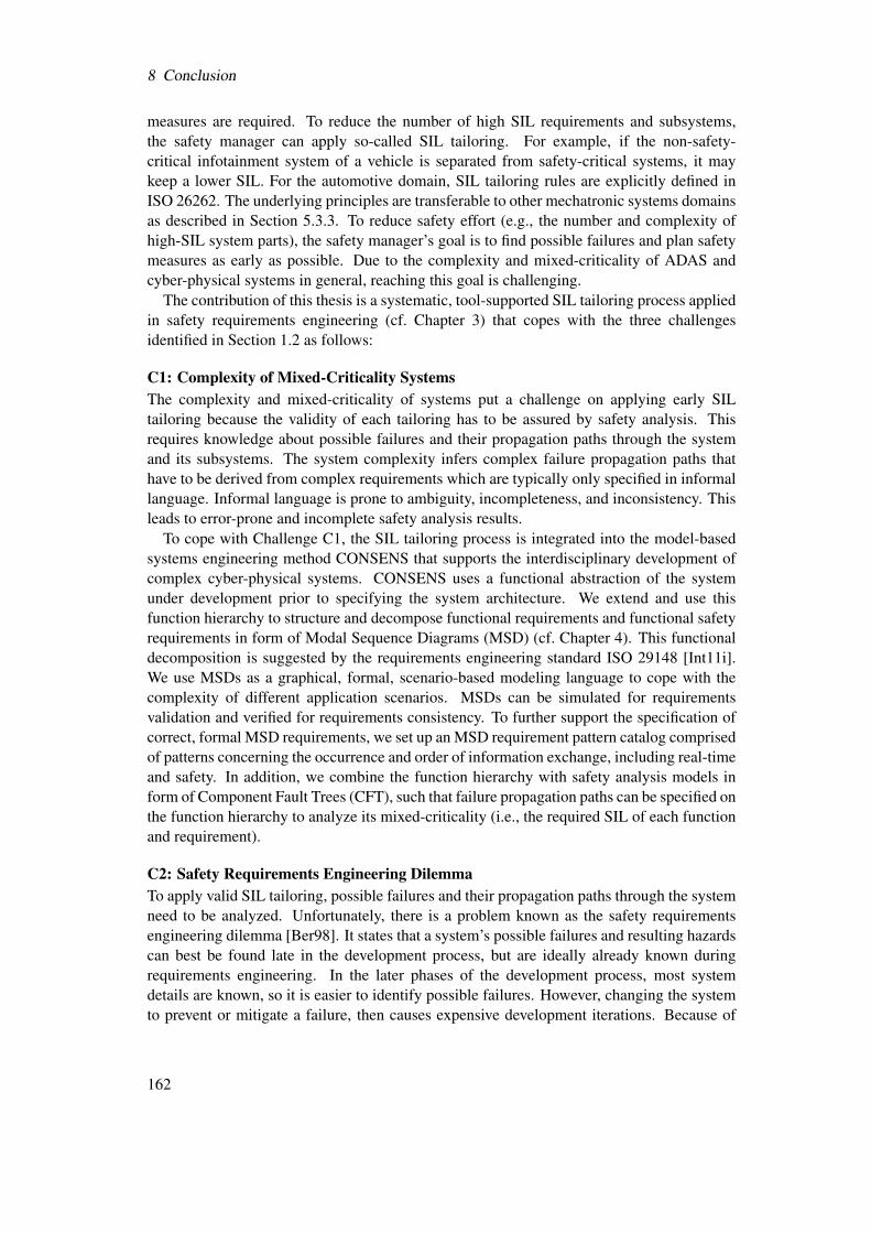
8 Conclusion
measures are required. To reduce the number of high SIL requirements and subsystems,the safety manager can apply so-called SIL tailoring. For example, if the non-safety-critical infotainment system of a vehicle is separated from safety-critical systems, it maykeep a lower SIL. For the automotive domain, SIL tailoring rules are explicitly defined inISO 26262. The underlying principles are transferable to other mechatronic systems domainsas described in Section 5.3.3. To reduce safety effort (e.g., the number and complexity ofhigh-SIL system parts), the safety manager’s goal is to find possible failures and plan safetymeasures as early as possible. Due to the complexity and mixed-criticality of ADAS andcyber-physical systems in general, reaching this goal is challenging.
The contribution of this thesis is a systematic, tool-supported SIL tailoring process appliedin safety requirements engineering (cf. Chapter 3) that copes with the three challengesidentified in Section 1.2 as follows:
C1: Complexity of Mixed-Criticality SystemsThe complexity and mixed-criticality of systems put a challenge on applying early SILtailoring because the validity of each tailoring has to be assured by safety analysis. Thisrequires knowledge about possible failures and their propagation paths through the systemand its subsystems. The system complexity infers complex failure propagation paths thathave to be derived from complex requirements which are typically only specified in informallanguage. Informal language is prone to ambiguity, incompleteness, and inconsistency. Thisleads to error-prone and incomplete safety analysis results.
To cope with Challenge C1, the SIL tailoring process is integrated into the model-basedsystems engineering method CONSENS that supports the interdisciplinary development ofcomplex cyber-physical systems. CONSENS uses a functional abstraction of the systemunder development prior to specifying the system architecture. We extend and use thisfunction hierarchy to structure and decompose functional requirements and functional safetyrequirements in form of Modal Sequence Diagrams (MSD) (cf. Chapter 4). This functionaldecomposition is suggested by the requirements engineering standard ISO 29148 [Int11i].We use MSDs as a graphical, formal, scenario-based modeling language to cope with thecomplexity of different application scenarios. MSDs can be simulated for requirementsvalidation and verified for requirements consistency. To further support the specification ofcorrect, formal MSD requirements, we set up an MSD requirement pattern catalog comprisedof patterns concerning the occurrence and order of information exchange, including real-timeand safety. In addition, we combine the function hierarchy with safety analysis models inform of Component Fault Trees (CFT), such that failure propagation paths can be specified onthe function hierarchy to analyze its mixed-criticality (i.e., the required SIL of each functionand requirement).
C2: Safety Requirements Engineering DilemmaTo apply valid SIL tailoring, possible failures and their propagation paths through the systemneed to be analyzed. Unfortunately, there is a problem known as the safety requirementsengineering dilemma [Ber98]. It states that a system’s possible failures and resulting hazardscan best be found late in the development process, but are ideally already known duringrequirements engineering. In the later phases of the development process, most systemdetails are known, so it is easier to identify possible failures. However, changing the systemto prevent or mitigate a failure, then causes expensive development iterations. Because of
162

8.1 Summary
the missing knowledge about possible failures and their propagation paths, safety analyseson the requirements level are prone to incompleteness. Whenever new information aboutfailures is gained, the safety analyses have to be repeated. As this produces manual effort,in practice, safety analyses are currently not applied on the requirements level, and existingresearch approaches apply SIL tailoring on technical architectures only.
To cope with Challenge C2, we contribute a concept and prototypical implementationthat automatically generates CFT failure propagation models for a function hierarchy basedon functional (safety) requirements specified as MSDs (cf. Section 5.2). Furthermore,we contribute a concept and prototypical implementation that uses the failure propagationmodels to automatically calculate a SIL allocation to functions and requirements,incorporating applied SIL tailorings (cf. Section 5.3). These automated process stepsminimize the manual effort to a review of the generated models and SIL allocation.Additionally, these automated steps can be repeated whenever changes to the functionhierarchy or requirements are made.
C3: Safety Case Construction and MaintenanceSafety standards like the ISO 26262 require a so-called safety case, which provides the“argument that the safety requirements for an item are complete and satisfied by evidencecompiled from work products of the safety activities during development” [Int11a]. Thesafety manager has to argue the validity of each applied SIL tailoring in the safety case.As safety analyses are time-consuming and error-prone in early development stages (cf.previous challenges), SIL tailoring is applied on technical architectures rather than functionalmodels of the requirements analysis phase. Consequently, safety cases are not built inthat phase either. Building a safety case with arguments for valid early SIL tailoringrequires traceability throughout the whole development process (from the initial hazardsto the safety requirements, to introduced safety mechanisms, to safety analysis results).Reverse engineering that information to build the safety case in the end of development, isa tedious and error-prone task that may identify missing safety measures and, thus, causeexpensive process iterations. Existing research approaches describe ways to documentmodel-based safety cases and safety case patterns. However, there is no approach thatautomatically constructs and maintains the safety case according to applied SIL tailorings onthe requirements level. Safety case automation in general was identified as open challenge[HWK+14].
To cope with Challenge C3, we contribute a concept and prototypical implementation thatautomatically derives model-based safety cases using the Goal Structuring Notation (GSN)from the SIL allocated functions, MSD requirements, and CFT failure propagation model(cf. Chapter 6). The generated safety cases include assurance arguments for the validity ofapplied SIL tailorings. This automated derivation of safety arguments minimizes manualeffort for safety case maintenance, as it can be repeated to update the safety case whenevernew hazards are identified or changes to the safety requirements are made.
Altogether, the presented SIL tailoring process integrates concepts of model-based safetyengineering with model-based requirements and systems engineering to support the safetymanager in planning safety effort on early functional requirements. The evaluation (cf.Chapter 7) showed that the automated process steps for safety analysis, SIL allocation, andsafety argumentation save time and avoid manually introduced errors.
163

8 Conclusion
8.2 Future Work
The results of this thesis give rise to possibilities for future research that we highlight in thefollowing. Firstly, future work may enhance the contributions of this thesis by overcomingthe limitations and relaxing the assumptions that we described in the corresponding Sections3.7, 4.6, 5.4, and 6.3. In addition, the presented SIL tailoring process should be evaluated infurther projects and mechatronic systems domains. In the following paragraphs, we discussfurther directions for future research.
For generating CFT failure propagation models, we assume that requirements are specifiedsolely using our catalog of MSD requirement patterns. In future work, it could be evaluatedwhat has to be changed, such that the CFT generation works for arbitrary MSDs that donot necessarily conform to any of the patterns. Although the catalog is helpful to specifyrequirements correctly to one’s intents, this would increase the applicability and robustnessof our approach.
For requirements that cannot be specified as MSDs (e.g., quality requirements concerningthe failure rate of a system), we provide a bidirectional transformation of the functionhierarchy to textual requirements using patterns in a controlled natural language (cf.Section 4.5). To support requirements engineers that do not understand the MSD language,and to support requirements exchange with purely textual requirements management tools,it would be beneficial to also synchronize MSD requirements with a textual representation.This is a complex task, as a single MSD can be comprised of several atomic requirementsand a single requirement can be formalized using multiple MSDs. In addition, one has to findthe right balance between ambiguity and formality to not reinvent languages like Z [Int02]or CTL [EC82].
A further direction for future research is to adapt our approach to also work for followingdevelopment phases. Functional safety requirements are refined into technical safetyrequirements that have to be satisfied by the system architecture. For instance, if technicalsafety requirements can be specified using MSDs on the structural basis of the CONSENSactive structure, CFT failure propagation models could be generated from those MSDs. Then,the SIL allocation and GSN generation could be reused. The challenge of this research isto extend MSDs to work on the technical level or to find a different formal language thatcan be used for CFT generation. Especially requirements on continuous information flowlike feedback loops or flow of hydraulic fluids cannot be specified using the MSD languagedefinition used in this thesis [HFK+16].
The approach presented in this thesis supports the safety manager in analyzing andarguing safety of functions and their requirements including the validity of applied SILtailorings. As innovations and complexity of cyber-physical systems will increase, so willtheir requirements specifications. Hence, it will get more difficult to find valid SIL tailoringpossibilities. Therefore, it would support the safety manager, if there was an approach thatmakes suggestions how to change or evolve the function hierarchy and its requirements toenable or improve SIL tailorings. This is a huge challenge because the suggestion mechanismwill have to understand the semantics of requirements and incorporate knowledge aboutfunctionality cohesion and cost. Otherwise it will suggest many unreasonable solutions.
164

BIBLIOGRAPHY
The bibliography is structured into three parts: my own publications, the theses I supervised,and foreign literature. Details about my contributions to the papers listed under my ownpublications are given in Appendix B.
Own Publications
[FHK+18] FOCKEL, MARKUS; HOLTMANN, JÖRG; KOCH, THORSTEN;SCHMELTER, DAVID: “Formal, Model- and Scenario-based RequirementPatterns”. In: 6th International Conference on Model-Driven Engineering andSoftware Development (MODELSWARD 2018). Funchal, Portugal, Jan. 2018.
[FHK+17] FOCKEL, MARKUS; HOLTMANN, JÖRG; KOCH, THORSTEN;SCHMELTER, DAVID: Model-based Requirement Patterns. Tech. rep.tr-ri-17-354. Software Engineering Department, Fraunhofer IEM / SoftwareEngineering Group, Heinz Nixdorf Institute, Oct. 2017.
[Foc16] FOCKEL, MARKUS: “ASIL Tailoring on Functional Safety Requirements”.In: 5th International Workshop on Next Generation of System AssuranceApproaches for Safety-Critical Systems (SASSUR). Ed. bySKAVHAUG, AMUND; GUIOCHET, JÉRÉMIE; SCHOITSCH, ERWIN;BITSCH, FRIEDEMANN. Vol. 9923. LNCS. Co-located with SAFECOMP2016. Trondheim, Norway: Springer International Publishing, Sept. 2016.DOI: 10.1007/978-3-319-45480-1_24.
[HFK+16] HOLTMANN, JÖRG; FOCKEL, MARKUS; KOCH, THORSTEN;SCHMELTER, DAVID; BRENNER, CHRISTIAN; BERNIJAZOV, RUSLAN;SANDER, MARCEL: The MechatronicUML Requirements EngineeringMethod: Process and Language. Tech. rep. tr-ri-16-351. SoftwareEngineering Department, Fraunhofer IEM / Software Engineering Group,Heinz Nixdorf Institute, Dec. 2016.
[FH15] FOCKEL, MARKUS; HOLTMANN, JÖRG: “ReqPat: Efficient Documentationof High-quality Requirements using Controlled Natural Language”. In: Proc.of the 23rd International Requirements Engineering Conference 2015 (RE2015). Ottawa, Canada: IEEE, Aug. 2015, pp. 280–281. DOI:10.1109/RE.2015.7320438.
165

Supervised Theses
[MFH15] MEYER, JAN; FOCKEL, MARKUS; HOLTMANN, JÖRG: “Systementwurfunter Einbeziehung funktionaler Sicherheit bei automobilen Steuergeräten”.In: Tag des Systems Engineering 2015 (TdSE 2015). (in German). Ulm,Germany, Nov. 2015.
[FH14] FOCKEL, MARKUS; HOLTMANN, JÖRG: “A Requirements EngineeringMethodology Combining Models and Controlled Natural Language”. In: 4thInternational Model-Driven Requirements Engineering Workshop (MoDRE).Co-located with RE 2014. Karlskrona, Sweden: IEEE, Aug. 2014, pp. 67–76.DOI: 10.1109/MoDRE.2014.6890827.
[FHM14] FOCKEL, MARKUS; HOLTMANN, JÖRG; MEYER, MATTHIAS: “MitSatzmustern hochwertige Anforderungsdokumente effizient erstellen”. In:OBJEKTspektrum RE/2014 (June 2014). (Online ThemenspecialRequirements Engineering) (in German).
[DFH+13] DAUN, MARIAN; FOCKEL, MARKUS; HOLTMANN, JÖRG;TENBERGEN, BASTIAN: Goal-Scenario-Oriented Requirements Engineeringfor Functional Decomposition with Bidirectional Transformation toControlled Natural Language. Case Study "Body Control Module". Tech. rep.ICB-Research Report No. 55. Universität Duisburg-Essen, May 2013.
[FHH+12] FOCKEL, M.; HEIDL, P.; HOLTMANN, J.; HORN, W.; HÖFFLINGER, J.;HÖNNINGER, H.; MEYER, J.; MEYER, M.; SCHÄUFFELE, J.: “Applicationand Evaluation in the Automotive Domain”. In: Model-Based Engineering ofEmbedded Systems: The SPES 2020 Methodology. Ed. by POHL, KLAUS;HÖNNINGER, HARALD; ACHATZ, REINHOLD E.; BROY, MANFRED.Springer, 2012. Chap. 12, pp. 157–175. ISBN: 978-3-642-34614-9 (Online),978-3-642-34613-2 (Print).
[FHM12] FOCKEL, MARKUS; HOLTMANN, JÖRG; MEYER, JAN: “Semi-automaticEstablishment and Maintenance of Valid Traceability in AutomotiveDevelopment Processes”. In: 2nd International Workshop on SoftwareEngineering for Embedded Systems (SEES). Co-located with ICSE 2012.Zürich, Switzerland, June 2012, pp. 37–43. ISBN: 978-1-4673-1853-2.
Supervised Theses
[BBB+16] BASAK, AINDRILA; BERNIJAZOV, RUSLAN; BÖRDING, PAUL;EIKERLING, HENDRIK; ENSTE, PATRICK; FLOHRE, ANDREAS;NEUMANN, CONRAD; STOLTE, FLORIAN: “Project Group Aramid”. FinalDocumentation. Paderborn: Paderborn University, 2016.
[Tre18] TRENTINAGLIA, ROMAN: “Deriving Pattern-based Safety Arguments”.Bachelor’s Thesis. Paderborn: Paderborn University, May 2018.
166

Foreign Publications
Foreign Publications
[Aca11] ACATECH, ed.: Cyber-Physical Systems – Innovationsmotor für Mobilität,Gesundheit, Energie und Produktion. acatech POSITION. Berlin/Heidelberg:Springer, 2011.
[ACD93] ALUR, R.; COURCOUBETIS, C.; DILL, D.: “Model-Checking in DenseReal-Time”. In: Information and Computation 104.1 (1993), pp. 2–34. DOI:http://dx.doi.org/10.1006/inco.1993.1024.
[Ass18] ASSURANCE CASE WORKING GROUP (ACWG): Goal StructuringNotation Community Standard. Version 2. Jan. 2018.
[AHK+08] ATIR, YORAM; HAREL, DAVID; KLEINBORT, ASAF; MAOZ, SHAHAR:“Object Composition in Scenario-Based Programming”. In: FundamentalApproaches to Software Engineering: 11th International Conference (FASE2008). Ed. by FIADEIRO, JOSÉ LUIZ; INVERARDI, PAOLA. Budapest,Hungary: Springer Berlin Heidelberg, Mar. 2008, pp. 301–316. DOI:10.1007/978-3-540-78743-3_23.
[AGL+15] AUTILI, M.; GRUNSKE, L.; LUMPE, M.; PELLICCIONE, P.; TANG, A.:“Aligning Qualitative, Real-Time, and Probabilistic Property SpecificationPatterns Using a Structured English Grammar”. In: IEEE Transactions onSoftware Engineering 41.7 (July 2015), pp. 620–638. DOI:10.1109/TSE.2015.2398877.
[AIP07] AUTILI, M.; INVERARDI, P.; PELLICCIONE, P.: “Graphical scenarios forspecifying temporal properties: an automated approach”. In: AutomatedSoftware Engineering 14.3 (2007), pp. 293–340. DOI:10.1007/s10515-007-0012-6.
[Aut10] AUTOMOTIVE SPECIAL INTEREST GROUP (SIG): Automotive SPICE:Process Reference Model, v4.5. 2010.
[ALR+04] AVIZIENIS, A.; LAPRIE, J.-C.; RANDELL, B.; LANDWEHR, C.: “Basicconcepts and taxonomy of dependable and secure computing”. In: IEEETransactions on Dependable and Secure Computing 1.1 (Jan. 2004),pp. 11–33. DOI: 10.1109/TDSC.2004.2.
[APW+14] AZEVEDO, L. S.; PARKER, D.; WALKER, M.; PAPADOPOULOS, Y.;ARAUJO, R. E.: “Assisted Assignment of Automotive Safety Requirements”.In: IEEE Software 31.1 (Jan. 2014), pp. 62–68. ISSN: 0740-7459. DOI:10.1109/MS.2013.118.
[APW+13] AZEVEDO, LUIS SILVA; PARKER, DAVID; WALKER, MARTIN;PAPADOPOULOS, YIANNIS; ARAUJO, RUI ESTEVES: “AutomaticDecomposition of Safety Integrity Levels: Optimization by Tabu Search”. In:2nd Workshop on Critical Automotive applications: Robustness & Safety,CARS 2013. 2013.
[Bah14] BAHR, NICHOLAS J.: System Safety Engineering and Risk Assessment. 2ndedition. CRC Press, 2014. ISBN: 9781466551619.
167

Foreign Publications
[Bai15] BAILEY, BRIAN: The Wild West of Automotive. Apr. 9, 2015. URL: http://semiengineering.com/the-wild-west-of-automotive/.
[BCF+14] BECKERS, KRISTIAN; CÔTÉ, ISABELLE; FRESE, THOMAS;HATEBUR, DENIS; HEISEL, MARITTA: “Systematic Derivation of FunctionalSafety Requirements for Automotive Systems”. In: Proceedings of the 33rdInternational Conference on Computer Safety, Reliability, and Security(SAFECOMP 2014). Ed. by BONDAVALLI, ANDREA;DI GIANDOMENICO, FELICITA. Florence, Italy: Springer InternationalPublishing, 2014, pp. 65–80. DOI: 10.1007/978-3-319-10506-2_5.
[Ber98] BERRY, D. M.: “The safety requirements engineering dilemma”. In: Procs.of the ninth Int. Workshop on Software Specification and Design. Apr. 1998,pp. 147–149. DOI: 10.1109/IWSSD.1998.667930.
[Bit00] BITSCH, FRIEDEMANN: “Classification of Safety Requirements for FormalVerification of Software Models of Industrial Automation Systems”. In:Procs. of the 13th Int. Conf. on Software and Systems Engineering and theirApplications (ICSSEA). Paris, France, 2000.
[Bit01] BITSCH, FRIEDEMANN: “Safety Patterns – The Key to Formal Specificationof Safety Requirements”. In: Proceedings of the 20th InternationalConference on Computer Safety, Reliability and Security (SAFECOMP2001). Ed. by VOGES, UDO. Budapest, Hungary: Springer Berlin Heidelberg,Sept. 2001, pp. 176–189. DOI: 10.1007/3-540-45416-0_18.
[BAB+12] BLANQUART, JEAN-PAUL; ASTRUC, JEAN-MARC;BAUFRETON, PHILIPPE; BOULANGER, JEAN-LOUIS; DELSENY, HERVÉ;GASSINO, JEAN; LADIER, GÉRARD; LEDINOT, EMMANUEL;LEEMAN, MICHEL; MACHROUH, JOSEPH; QUÉRÉ, PHILIPPE;RICQUE, BERTARND: “Criticality categories across safety standards indifferent domains”. In: Embedded Real Time Software and Systems (ERTS2012). Toulouse, France, Feb. 2012.
[BLH+13] BLOM, HANS; LÖNN, HENRIK; HAGL, FRANK;PAPADOPOULOS, YIANNIS; REISER, MARK-OLIVER;SJÖSTEDT, CARL-JOHAN; CHEN, DE-JIU; KOLAGARI, RAMIN TAVAKOLI:EAST-ADL – An Architecture Description Language for AutomotiveSoftware-Intensive Systems. White Paper. Version 2.1.12. 2013.
[BGH+14] BRENNER, CHRISTIAN; GREENYER, JOEL; HOLTMANN, JÖRG;LIEBEL, GRISCHA; STIEGLBAUER, GERALD; TICHY, MATTHIAS:“ScenarioTools Real-Time Play-Out for Test Sequence Validation in anAutomotive Case Study”. In: 13th Int. Workshop on Graph Transformationand Visual Modeling Techniques (GTVMT 2014). 2014.
[BGP13] BRENNER, CHRISTIAN; GREENYER, JOEL;PANZICA LA MANNA, VALERIO: “The ScenarioTools Play-Out of ModalSequence Diagram Specifications with Environment Assumptions”. In: 12thInt. Workshop on Graph Transformation and Visual Modeling Techniques(GTVMT 2013). 2013.
168

Foreign Publications
[BDH+12] BROY, M.; DAMM, W.; HENKLER, S.; POHL, K.; VOGELSANG, A.;WEYER, T.: “Introduction to the SPES Modeling Framework”. In:Model-Based Engineering of Embedded Systems: The SPES 2020Methodology. Ed. by POHL, KLAUS; HÖNNINGER, HARALD;ACHATZ, REINHOLD; BROY, MANFRED. Springer, 2012. Chap. 3,pp. 31–49. ISBN: 978-3-642-34614-9 (Online), 978-3-642-34613-2 (Print).
[CEN11] CENELEC: EN 50128:2011: Railway applications – Communication,signalling and processing systems – Software for railway control andprotection systems. 2011.
[Cha09] CHARETTE, ROBERT: “This Car Runs on Code”. In: IEEE Spectrum (Feb.2009).
[CJL+08] CHEN, DEJIU; JOHANSSON, ROLF; LÖNN, HENRIK;PAPADOPOULOS, YIANNIS; SANDBERG, ANDERS; TÖRNER, FREDRIK;TÖRNGREN, MARTIN: “Modelling Support for Design of Safety-CriticalAutomotive Embedded Systems”. In: 27th International Conference onComputer Safety, Reliability, and Security (SAFECOMP 2008). Ed. byHARRISON, MICHAEL D.; SUJAN, MARK-ALEXANDER. Newcastle uponTyne, UK: Springer Berlin Heidelberg, Sept. 2008, pp. 72–85. DOI:10.1007/978-3-540-87698-4_9.
[Cot13] COTNER, JOHN: Functional Safety and ISO 26262 Compliance -APF-AUT-T0503. presentation. Sept. 2013.
[Cro15] CROLLA, DAVID: Encyclopedia of Automotive Engineering. John Wiley &Sons, 2015. ISBN: 9780470974025.
[DP13] DENNEY, EWEN; PAI, GANESH: “A Formal Basis for Safety Case Patterns”.In: Proc. of the 32nd International Conference on Computer Safety,Reliability, and Security (SAFECOMP 2013). Ed. by BITSCH, F.;GUIOCHET, J.; KAANICHE, M. Vol. 8153. LNCS. Toulouse, France:Springer, Sept. 2013, pp. 21–32. DOI:10.1007/978-3-642-40793-2_3.
[Dep12] DEPARTMENT OF DEFENSE, USA: MIL-STD-882E: Department of DefenseStandard Practice – System Safety. 2012.
[DPS+14] DHOUIBI, MOHAMED SLIM; PERQUIS, JEAN-MARC; SAINTIS, LAURENT;BARREAU, MIHAELA: “Automatic Decomposition and Allocation of SafetyIntegrity Level Using System of Linear Equations”. In: Proc. of the 4thInternational Conference on Performance, Safety and Robustness in ComplexSystems and Applications (PESARO 2014). 2014. ISBN: 978-1-61208-321-6.
[Dor14] DOROCIAK, RAFAL: “Systematik zur frühzeitigen Absicherung derSicherheit und Zuverlässigkeit fortschrittlicher mechatronischer Systeme”.PhD thesis. Paderborn, Germany: Paderborn University, 2014.
[DAC99] DWYER, M. B.; AVRUNIN, G. S.; CORBETT, J. C.: “Patterns in propertyspecifications for finite-state verification”. In: Proceedings of the 1999International Conference on Software Engineering (ICSE 99). Los Angeles,USA, May 1999, pp. 411–420. DOI: 10.1145/302405.302672.
169

Foreign Publications
[EAS10] EAST-ADL ASSOCIATION: UML Profile of EAST-ADL Domain ModelSpecification, v2.1.0. 2010.
[EAS13] EAST-ADL ASSOCIATION: EAST-ADL Domain Model Specification,v2.1.12. 2013.
[EJ09] EBERT, C.; JONES, C.: “Embedded Software: Facts, Figures, and Future”. In:IEEE Computer 42.4 (Apr. 2009), pp. 42–52. ISSN: 0018-9162. DOI:10.1109/MC.2009.118.
[EC82] EMERSON, E. ALLEN; CLARKE, EDMUND M.: “Using branching timetemporal logic to synthesize synchronization skeletons”. In: Science ofComputer Programming 2.3 (1982), pp. 241–266. DOI:http://dx.doi.org/10.1016/0167-6423(83)90017-5.
[Eri05] ERICSON, CLIFTON A.: “Event Tree Analysis”. In: Hazard AnalysisTechniques for System Safety. John Wiley & Sons, Inc., 2005, pp. 223–234.ISBN: 9780471739425.
[Eur14] EUROPEAN NEW CAR ASSESSMENT PROGRAMME (EURO NCAP): Testprotocol – AEB systems v1.0. Jan. 2014. URL: http://euroncap.blob.core.windows.net/media/1569/aeb-test-protocol-v-10.pdf.
[GRS14] GAUSEMEIER, J.; RAMMIG, F.-J.; SCHÄFER, W.: “Design Methodology forIntelligent Technical Systems”. In: Lecture Notes in Mechanical Engineering.Springer, 2014.
[GPD+09] GAUSEMEIER, JÜRGEN; PÖSCHL, MARTIN; DEYTER, SEBASTIAN;KAISER, LYDIA: “Modeling and analyzing fault-tolerant mechatronicsystems”. In: Proceedings of the 17th International Conference onEngineering Design (ICED 09). Stanford, USA, Aug. 2009.
[GTS04] GIESE, HOLGER; TICHY, MATTHIAS; SCHILLING, DANIELA:“Compositional Hazard Analysis of UML Component and DeploymentModels”. In: SAFECOMP 2004. Potsdam, Germany: Springer, 2004. DOI:10.1007/978-3-540-30138-7_15.
[GH09] GORDON, MICHAL; HAREL, DAVID: “Generating Executable Scenariosfrom Natural Language”. In: Computational Linguistics and Intelligent TextProcessing. Ed. by GELBUKH, ALEXANDER. Berlin, Heidelberg: SpringerBerlin Heidelberg, 2009, pp. 456–467. DOI:10.1007/978-3-642-00382-0_37.
[Gre11] GREENYER, JOEL: “Scenario-based Design of Mechatronic Systems”.PhD thesis. Paderborn, Germany: Paderborn University, 2011.
[GBC+13] GREENYER, JOEL; BRENNER, CHRISTIAN; CORDY, MAXIME;HEYMANS, PATRICK; GRESSI, ERIKA: “Incrementally SynthesizingControllers from Scenario-based Product Line Specifications”. In: 9th JointMeeting of the ESEC/FSE. New York, NY, USA: ACM, 2013, pp. 433–443.DOI: 10.1145/2491411.2491445.
170

Foreign Publications
[GGK+16] GREENYER, JOEL; GRITZNER, DANIEL; KATZ, GUY; MARRON, ASSAF:“Scenario-Based Modeling and Synthesis for Reactive Systems withDynamic System Structure in ScenarioTools”. In: MoDELS 2016 Demo andPoster Sessions. Vol. 1725. 2016, pp. 16–32.
[GHM+15] GREENYER, JOEL; HAASE, MAX; MARHENKE, JÖRG; BELLMER, RENE:“Evaluating a Formal Scenario-based Method for the Requirements Analysisin Automotive Software Engineering”. In: Proceedings of the 10th JointMeeting on Foundations of Software Engineering (ESEC/FSE 2015).ESEC/FSE 2015. Bergamo, Italy: ACM, 2015, pp. 1002–1005. DOI:10.1145/2786805.2804432.
[HM08] HAREL, DAVID; MAOZ, SHAHAR: “Assert and negate revisited: Modalsemantics for UML sequence diagrams”. In: Software & Systems Modeling7.2 (2008), pp. 237–252.
[HWK+14] HATCLIFF, JOHN; WASSYNG, ALAN; KELLY, TIM; COMAR, CYRILLE;JONES, PAUL: “Certifiably Safe Software-dependent Systems: Challengesand Directions”. In: Future of Software Engineering. FOSE 2014. Hyderabad,India: ACM, 2014, pp. 182–200. DOI: 10.1145/2593882.2593895.
[HTZ+12] HÖFIG, KAI; TRAPP, MARIO; ZIMMER, BASTIAN; LIGGESMEYER, PETER:“Modeling Quality Aspects: Safety”. In: Model-Based Engineering ofEmbedded Systems: The SPES 2020 Methodology. Ed. by POHL, KLAUS;HÖNNINGER, HARALD; ACHATZ, REINHOLD; BROY, MANFRED.Springer-Verlag, 2012, pp. 107–118. ISBN: 978-3-642-34613-2.
[HBM+16] HOLTMANN, JÖRG; BERNIJAZOV, RUSLAN; MEYER, MATTHIAS;SCHMELTER, DAVID; TSCHIRNER, CHRISTIAN: “Integrated and iterativesystems engineering and software requirements engineering for technicalsystems”. In: Journal of Software Evolution and Process (May 2016).
[HM13] HOLTMANN, JÖRG; MEYER, MATTHIAS: “Play-out for HierarchicalComponent Architectures”. In: 11th Workshop Automotive SoftwareEngineering. Vol. P-220. GI-Edition - Lecture Notes in Informatics (LNI).Bonner Köllen Verlag, 2013.
[Ins12] INSTITUTE OF ELECTRICAL AND ELECTRONICS ENGINEERS (IEEE):IEEE 802.11-2012: IEEE Standard for Information technology –Telecommunications and information exchange between systems, Local andmetropolitan area networks – Specific requirements Part 11. 2012.
[Int15] INTERNATIONAL COUNCIL ON SYSTEMS ENGINEERING (INCOSE):Systems Engineering Handbook: A guide for system life cycle processes andactivities. 4th edition. Wiley, 2015. ISBN: 9781118999400.
[Int01] INTERNATIONAL ELECTROTECHNICAL COMMISSION (IEC): IEC61882:2001: Hazard and operability studies (HAZOP studies) – Applicationguide. 2001.
[Int03] INTERNATIONAL ELECTROTECHNICAL COMMISSION (IEC): IEC60300-3-1:2003: Dependability management – Part 3-1: Application guide –Analysis techniques for dependability – Guide on methodology. 2003.
171

Foreign Publications
[Int05] INTERNATIONAL ELECTROTECHNICAL COMMISSION (IEC): IEC62061:2005: Safety of machinery – Functional safety of safety-relatedelectrical, electronic and programmable electronic control systems. 2005.
[Int06a] INTERNATIONAL ELECTROTECHNICAL COMMISSION (IEC): IEC60812:2006: Analysis techniques for system reliability – Procedure forfailure mode and effects analysis (FMEA). 2006.
[Int06b] INTERNATIONAL ELECTROTECHNICAL COMMISSION (IEC): IEC61025:2006: Fault tree analysis (FTA). 2006.
[Int06c] INTERNATIONAL ELECTROTECHNICAL COMMISSION (IEC): IEC61165:2006: Application of Markov techniques. 2006.
[Int10a] INTERNATIONAL ELECTROTECHNICAL COMMISSION (IEC): IEC61508:2010: Functional safety of electrical/electronic/programmableelectronic safety-related systems. 2010.
[Int02] INTERNATIONAL ORGANIZATION FOR STANDARDIZATION (ISO): ISO13568:2002: Information technology – Z formal specification notation –Syntax, type system and semantics. 2002.
[Int08] INTERNATIONAL ORGANIZATION FOR STANDARDIZATION (ISO): ISO15288:2008(E): Systems and software engineering – System life cycleprocesses. 2008.
[Int10b] INTERNATIONAL ORGANIZATION FOR STANDARDIZATION (ISO): ISO25119:2010: Tractors and machinery for agriculture and forestry –Safety-related parts of control systems. 2010.
[Int11a] INTERNATIONAL ORGANIZATION FOR STANDARDIZATION (ISO): ISO26262-1:2011(E): Road vehicles – Functional safety. Part 1: Vocabulary.2011.
[Int11b] INTERNATIONAL ORGANIZATION FOR STANDARDIZATION (ISO): ISO26262:2011(E): Road vehicles – Functional safety. 2011.
[Int11c] INTERNATIONAL ORGANIZATION FOR STANDARDIZATION (ISO): ISO26262-2:2011(E): Road vehicles – Functional safety. Part 2: Management offunctional safety. 2011.
[Int11d] INTERNATIONAL ORGANIZATION FOR STANDARDIZATION (ISO): ISO26262-3:2011(E): Road vehicles – Functional safety. Part 3: Concept phase.2011.
[Int11e] INTERNATIONAL ORGANIZATION FOR STANDARDIZATION (ISO): ISO26262-4:2011(E): Road vehicles – Functional safety. Part 4: Productdevelopment at the system level. 2011.
[Int11f] INTERNATIONAL ORGANIZATION FOR STANDARDIZATION (ISO): ISO26262-6:2011(E): Road vehicles – Functional safety. Part 6: Productdevelopment at the software level. 2011.
[Int11g] INTERNATIONAL ORGANIZATION FOR STANDARDIZATION (ISO): ISO26262-8:2011(E): Road vehicles – Functional safety. Part 8: Supportingprocesses. 2011.
172

Foreign Publications
[Int11h] INTERNATIONAL ORGANIZATION FOR STANDARDIZATION (ISO): ISO26262-9:2011(E): Road vehicles – Functional safety. Part 9: ASIL-orientedand safety-oriented analyses. 2011.
[Int11i] INTERNATIONAL ORGANIZATION FOR STANDARDIZATION (ISO): ISO29148:2011(E): Systems and software engineering – Life cycle processes –Requirements engineering. 2011.
[Int12a] INTERNATIONAL ORGANIZATION FOR STANDARDIZATION (ISO): ISO15504-5:2012: Information technology – Process assessment – Part 5: Anexemplar software life cycle process assessment model. 2012.
[Int12b] INTERNATIONAL ORGANIZATION FOR STANDARDIZATION (ISO): ISO26262-10:2012(E): Road vehicles – Functional safety. Part 10: Guideline onISO 26262. 2012.
[IG14] INTERNATIONAL REQUIREMENTS ENGINEERING BOARD IREB E.V.;GLINZ, MARTIN: A Glossary of Requirements Engineering Terminology –Standard Glossary for the Certified Professional for RequirementsEngineering (CPRE) Studies and Exam. Version 1.6. May 2014.
[Inv14] INVENSITY GMBH: Automobilindustrie: 90 Prozent der Innovationen findenbei Elektronik und Software statt. press release. Apr. 29, 2014. URL: http://blog.invensity.com/2014/04/29/automobilindustrie-90-prozent-der-innovationen-finden-bei-elektronik-und-software-statt/.
[ISS08] ISERMANN, R.; SCHORN, M.; STÄHLIN, U.: “Anticollision systemPRORETA with automatic braking and steering”. In: Vehicle SystemDynamics 46.sup1 (2008), pp. 683–694. DOI:10.1080/00423110802036968.
[IKD+13] IWANEK, PETER; KAISER, LYDIA; DUMITRESCU, ROMAN;NYSSEN, ALEXANDER: “Fachdisziplinübergreifende Systemmodellierungmechatronischer Systeme mit SysML und CONSENS”. In: Tag des SystemsEngineering 2013. 2013.
[KLM03] KAISER, BERNHARD; LIGGESMEYER, PETER; MÄCKEL, OLIVER: “A NewComponent Concept for Fault Trees”. In: 8th Australian workshop on Safetycritical systems and software. 2003.
[KDH+13] KAISER, LYDIA; DUMITRESCU, ROMAN; HOLTMANN, JÖRG;MEYER, MATTHIAS: “Automatic Verification of Modeling Rules in SystemsEngineering for Mechatronic Systems”. In: Proceedings of the ASMEInternational Design Engineering Technical Conferences & Computers andInformation in Engineering Conference. ASME, July 2013.
[Kel98] KELLY, T. P.: “Arguing Safety - A Systematic Approach to Safety CaseManagement”. PhD thesis. York, UK: University of York, Sept. 1998.
173

Foreign Publications
[KM97] KELLY, T. P.; MCDERMID, J. A.: “Safety Case Construction and ReuseUsing Patterns”. In: Proceedings of the 16th International Conference onComputer Safety, Reliability and Security (SAFECOMP 97). Ed. byDANIEL, PETER. York, UK, Sept. 1997, pp. 55–69. DOI:10.1007/978-1-4471-0997-6_5.
[KPP95] KITCHENHAM, B.; PICKARD, L.; PFLEEGER, S. L.: “Case studies formethod and tool evaluation”. In: IEEE Software 12.4 (July 1995), pp. 52–62.DOI: 10.1109/52.391832.
[KC05] KONRAD, SASCHA; CHENG, BETTY H. C.: “Real-time specificationpatterns”. In: Proceedings of the 27th International Conference on SoftwareEngineering (ICSE 2005). 2005, p. 372. DOI:10.1145/1062455.1062526.
[KHP+05] KUGLER, HILLEL; HAREL, DAVID; PNUELI, AMIR; LU, YUAN;BONTEMPS, YVES: “Temporal Logic for Scenario-Based Specifications”. In:Proceedings of the 11th International Conference on Tools and Algorithmsfor the Construction and Analysis of Systems (TACAS 2005). Ed. byHALBWACHS, NICOLAS; ZUCK, LENORE D. Edinburgh, UK: SpringerBerlin Heidelberg, Apr. 2005, pp. 445–460. DOI:10.1007/978-3-540-31980-1_29.
[Kus16] KUSS, INGO: Audi zFAS – Enorme Datenmengen bewältigen. July 1, 2016.URL: http://www.elektroniknet.de/automotive/assistenzsysteme/artikel/131797/.
[LF09] LAMI, GIUSEPPE; FALCINI, FABIO: “Is ISO/IEC 15504 Applicable to AgileMethods?” In: Proceedings of the 10th International Conference on AgileProcesses in Software Engineering and Extreme Programming (XP 2009).Ed. by ABRAHAMSSON, PEKKA; MARCHESI, MICHELE;MAURER, FRANK. Pula, Italy: Springer Berlin Heidelberg, May 2009,pp. 130–135. DOI: 10.1007/978-3-642-01853-4_16.
[LW10] LAMM, J. G.; WEILKIENS, T.: “Funktionale Architekturen in SysML”. In:Tag des Systems Engineering 2010. Ed. by MAURER, M.; SCHULZE, S.-O.Munich, Germany: Carl Hanser Verlag, 2010.
[LW14] LAMM, JESKO G.; WEILKIENS, TIM: “Method for Deriving FunctionalArchitectures from Use Cases”. In: Syst. Eng. 17.2 (June 2014), pp. 225–236.DOI: 10.1002/sys.21265.
[Lam77] LAMPORT, LESLIE: “Proving the Correctness of Multiprocess Programs”. In:IEEE Transactions on Software Engineering SE-3.2 (Mar. 1977),pp. 125–143. DOI: 10.1109/TSE.1977.229904.
[LLN+09] LARSEN, KIM G.; LI, SHUHAO; NIELSEN, BRIAN; PUSINSKAS, SAULIUS:“Verifying Real-Time Systems against Scenario-Based Requirements”. In:Formal Methods: Second World Congress (FM 2009). Proceedings. Ed. byCAVALCANTI, ANA; DAMS, DENNIS R. Eindhoven, The Netherlands:Springer Berlin Heidelberg, Nov. 2009, pp. 676–691. DOI:10.1007/978-3-642-05089-3_43.
174

Foreign Publications
[LGP11] LAUER, CHRISTOPH; GERMAN, REINHARD; POLLMER, JENS: “Fault TreeSynthesis from UML Models for Reliability Analysis at Early DesignStages”. In: SIGSOFT Softw. Eng. Notes 36.1 (Jan. 2011), pp. 1–8. DOI:10.1145/1921532.1921558.
[LYZ+11] LI, W.; YANG, Z.; ZHANG, P.; WANG, Z.: “Model Checking WS-BPEL withUniversal Modal Sequence Diagrams”. In: 10th IEEE/ACIS InternationalConference on Computer and Information Science. May 2011, pp. 328–333.DOI: 10.1109/ICIS.2011.58.
[MAL+11] MADER, ROLAND; ARMENGAUD, ERIC; LEITNER, ANDREA;KREINER, CHRISTIAN; BOURROUILH, QUENTIN; GRIESSNIG, GERHARD;STEGER, CHRISTIAN; WEISS, REINHOLD: “Computer-Aided PHA, FTA andFMEA for Automotive Embedded Systems”. In: Computer Safety, Reliability,and Security (SAFECOMP 2011). Ed. by FLAMMINI, FRANCESCO;BOLOGNA, SANDRO; VITTORINI, VALERIA. Springer Berlin Heidelberg,2011, pp. 113–127. DOI: 10.1007/978-3-642-24270-0_9.
[MAL+12] MADER, ROLAND; ARMENGAUD, ERIC; LEITNER, ANDREA;STEGER, CHRISTIAN: “Automatic and optimal allocation of safety integritylevels”. In: Proc. of the Annual Reliability and Maintainability Symposium,RAMS 2012. IEEE, 2012, pp. 1–6. ISBN: 978-1-4577-1849-6. DOI:10.1109/RAMS.2012.6175431.
[MEP+05] MCKELVIN Jr., MARK L.; EIREA, GABRIEL; PINELLO, CLAUDIO;KANAJAN, SRI; SANGIOVANNI-VINCENTELLI, ALBERTO L.: “A FormalApproach to Fault Tree Synthesis for the Analysis of Distributed FaultTolerant Systems”. In: Proceedings of the 5th ACM International Conferenceon Embedded Software. EMSOFT ’05. Jersey City, NJ, USA: ACM, 2005,pp. 237–246. DOI: 10.1145/1086228.1086272.
[MZH+16] MÖHRLE, FELIX; ZELLER, MARC; HÖFIG, KAI; ROTHFELDER, MARTIN;LIGGESMEYER, PETER: “Automating Compositional Safety Analysis Usinga Failure Type Taxonomy for Component Fault Trees”. In: 26th EuropeanSafety and Reliability Conference (ESREL 2016). Glasgow, UK, Sept. 2016.
[NT09] NICOLÁS, J.; TOVAL, A.: “On the Generation of RequirementsSpecifications from Software Engineering Models: A Systematic LiteratureReview”. In: Information and Software Technology 51.9 (2009),pp. 1291–1307. DOI: 10.1016/j.infsof.2009.04.001.
[Obj15a] OBJECT MANAGEMENT GROUP (OMG): OMG Systems ModelingLanguage (OMG SysML). Version 1.4. 2015.
[Obj15b] OBJECT MANAGEMENT GROUP (OMG): OMG Unified Modeling Language(OMG UML). Version 2.5. 2015.
[PBF+06] PAHL, G.; BEITZ, W.; FELDHUSEN, J.; GROTE, K.-H.: Engineering Design:A Systematic Approach. Springer, 2006. ISBN: 978-1846283185.
175

Foreign Publications
[PLB+10] PAPADOPOULOS, Y.; LONN, H.; BERNTSSON, L.; JOHANSSON, ROLF;TAGLIABO, F.; TORCHIARO, S.; SANDBERG, ANDERS; WALKER, M.;REISER, M.-O; WEBER, M.; CHEN, D.; TÖRNGREN, M.; SERVAT, DAVID;ABELE, A.; STAPPERT, F.: “Automatic allocation of safety integrity levels”.In: 1st Workshop on Critical Automotive applications: Robustness & Safety,CARS. 2010. DOI: 10.1145/1772643.1772646.
[PM99] PAPADOPOULOS, YIANNIS; MCDERMID, JOHN A.: “HierarchicallyPerformed Hazard Origin and Propagation Studies”. In: Proc. of the 18th Int.Conf. on Computer safety, reliability, and security, SAFECOMP 99. Ed. byFELICI, M.; KANOUN, K.; PASQUINI, A. Vol. 1698. LNCS. Springer, 1999.DOI: 10.1007/3-540-48249-0\_13.
[PHS13] PRIESTERJAHN, CLAUDIA; HEINZEMANN, CHRISTIAN;SCHÄFER, WILHELM: “From Timed Automata to Timed Failure PropagationGraphs”. In: Proceedings of the Fourth IEEE Workshop on Self-OrganizingReal-time Systems (SORT 2013). IEEE, 2013.
[RPS+17] RETOUNIOTIS, ATHANASIOS; PAPADOPOULOS, YIANNIS;SOROKOS, IOANNIS; PARKER, DAVID; MATRAGKAS, NICHOLAS;SHARVIA, SEPTAVERA: “Model-Connected Safety Cases”. In: Model-BasedSafety and Assessment. Ed. by BOZZANO, MARCO;PAPADOPOULOS, YIANNIS. Springer International Publishing, 2017,pp. 50–63. DOI: 10.1007/978-3-319-64119-5_4.
[RH08] RUNESON, PER; HÖST, MARTIN: “Guidelines for conducting and reportingcase study research in software engineering”. In: Empirical SoftwareEngineering 14.2 (Dec. 19, 2008). DOI:10.1007/s10664-008-9102-8.
[SAE10] SAE INTERNATIONAL: ARP4754A:2010: Guidelines for Development ofCivil Aircraft and Systems. 2010.
[Saf17] SAFAR, MONA: “ASIL decomposition using SMT”. In: 2017 Forum onSpecification and Design Languages (FDL). Sept. 2017. DOI:10.1109/FDL.2017.8303902.
[SCL+10] SANDBERG, ANDERS; CHEN, DEJIU; LÖNN, HENRIK; JOHANSSON, ROLF;FENG, LEI; TÖRNGREN, MARTIN; TORCHIARO, SANDRA;TAVAKOLI-KOLAGARI, RAMIN; ABELE, ANDREAS: “Model-Based SafetyEngineering of Interdependent Functions in Automotive Vehicles UsingEAST-ADL2”. In: Proceedings of the 29th International Conference onComputer Safety, Reliability, and Security (SAFECOMP 2010). Ed. bySCHOITSCH, ERWIN. Vienna, Austria: Springer Berlin Heidelberg, Sept.2010, pp. 332–346. DOI: 10.1007/978-3-642-15651-9_25.
[SSK14] SCHARL, ADAM; STOTTLAR, KEVIN; KADY, RANI: “Functional HazardAnalysis (FHA) Methodology Tutorial”. In: International System SafetyTraining Symposium 2014. St. Louis, USA, Aug. 2014.
176

Foreign Publications
[Sch97] SCHWABER, KEN: “SCRUM Development Process”. In: Business ObjectDesign and Implementation: OOPSLA ’95 Workshop Proceedings (16thOctober 1995). Ed. by SUTHERLAND, JEFF; CASANAVE, CORY;MILLER, JOAQUIN; PATEL, PHILIP; HOLLOWELL, GLENN. Austin, USA:Springer London, 1997, pp. 117–134. DOI:10.1007/978-1-4471-0947-1_11.
[She96] SHEARD, SARAH A.: “Twelve Systems Engineering Roles”. In: Proceedingsof the INCOSE Sixth Annual International Symposium. Boston, USA, 1996.
[SPB16] SOROKOS, IOANNIS; PAPADOPOULOS, YIANNIS; BOTTACI, LEONARDO:“Maintaining Safety Arguments via Automatic Allocation of SafetyRequirements”. In: Proc. of the 3rd IFAC Workshop on AdvancedMaintenance Engineering, Services and Technology (AMEST 2016). 2016.DOI: https://doi.org/10.1016/j.ifacol.2016.11.005.
[Tes16] TESLA MOTORS: A Tragic Loss. press release. June 30, 2016. URL:https://www.tesla.com/blog/tragic-loss.
[Tut10] TUTU, ANDREI: Continental Emergency Steer Assist Explained. June 24,2010. URL:https://www.autoevolution.com/news/continental-emergency-steer-assist-explained-21731.html.
[VDI04] VDI: VDI 2206: Design methodology for mechatronic systems. VereinDeutscher Ingenieure, 2004.
[VEF+12] VOGELSANG, A.; EDER, S.; FEILKAS, M.; RATIU, D.: “FunctionalViewpoint”. In: Model-Based Engineering of Embedded Systems: The SPES2020 Methodology. Ed. by POHL, KLAUS; HÖNNINGER, HARALD;ACHATZ, REINHOLD; BROY, MANFRED. Springer, 2012. Chap. 5,pp. 69–83. ISBN: 978-3-642-34614-9 (Online), 978-3-642-34613-2 (Print).
[WC12] WARD, D. D.; CROZIER, S. E.: “The uses and abuses of ASILdecomposition in ISO 26262”. In: 7th IET Int. Conf. on System Safety,incorporating the Cyber Security Conference 2012. Oct. 2012, pp. 1–6. DOI:10.1049/cp.2012.1523.
[Wei14] WEILKIENS, T.: Systems Engineering mit SysML/UML: Anforderungen,Analyse, Architektur. dpunkt.verlag, 2014. ISBN: 9783864915444.
[WHL+16] WINNER, H.; HAKULI, S.; LOTZ, F.; SINGER, C., eds.: Handbook of DriverAssistance Systems. Springer, 2016. ISBN: 978-3-319-12351-6. DOI:10.1007/978-3-319-12352-3.
[YBL11] YUE, T.; BRIAND, L.; LABICHE, Y.: “A systematic review of transformationapproaches between user requirements and analysis models”. In:Requirements Engineering 16.2 (2011), pp. 75–99. DOI:10.1007/s00766-010-0111-y.
177

Foreign Publications
[ZRH16] ZELLER, MARC; RATIU, DANIEL; HÖFIG, KAI: “Towards the Adoption ofModel-Based Engineering for the Development of Safety-Critical Systems inIndustrial Practice”. In: 5th International Workshop on Next Generation ofSystem Assurance Approaches for Safety-Critical Systems (SASSUR). Ed. bySKAVHAUG, AMUND; GUIOCHET, JÉRÉMIE; SCHOITSCH, ERWIN;BITSCH, FRIEDEMANN. Vol. 9923. LNCS. Springer International Publishing,Sept. 2016, pp. 322–333. DOI: 10.1007/978-3-319-45480-1\_26.
[ZF 16] ZF FRIEDRICHSHAFEN AG: ZF Mitigates Rear-End Collisions with NewElectronic Safety Assistant for Trucks. press release. June 29, 2016. URL:https://press.zf.com/site/press/en_de/microsites/press/list/release/release_23367.html.
[ZLG10] ZHANG, PENGCHENG; LI, BIXIN; GRUNSKE, LARS: “Timed PropertySequence Chart”. In: Journal of Systems and Software 83.3 (2010),pp. 371–390. DOI:http://dx.doi.org/10.1016/j.jss.2009.09.013.
178
LIST OF ABBREVIATIONS
ADAS Advanced Driver Assistance System, page 1
AgPL Agriculture Performance Level, page 22
ASIL Automotive Safety Integrity Level, page 1
bdd SysML block definition diagram, page 29
CCF Common Cause Failure, page 23
CF Cascading Failure, page 22
CFT Component Fault Tree, page 24
CNL Controlled natural language, page 86
CONSENS CONceptual design Specification technique for the ENgineering of complexSystems, page 28
CPS Cyber-Physical System, page 1
DAL Development Assurance Level, page 22
E/E Electrics/Electronics, page 2
EBEAS Emergency Braking & Evasion Assistance System, page 3
ECU Electronic Control Unit, page 1
FMEA Failure Mode and Effects Analysis, page 2
FSR Functional Safety Requirement, page 19
FTA Fault Tree Analysis, page 23
GSN Goal Structuring Notation, page 37
HARA Hazard Analysis & Risk Assessment, page 19
HW Hardware, page 7
ibd SysML internal block diagram, page 29
179

List of Abbreviations
ILP Integer Linear Program, page 116
MBRE Model-based Requirements Engineering, page 85
MSD Modal Sequence Diagram, page 34
NLRE Natural Language Requirements Engineering, page 85
RDS Rear Door System, page 152
SEooC Safety Element out of Context, page 57
SIL Safety Integrity Level, page 1
SUD System under development, page 9
SW Software, page 2
SyRS System Requirements Specification, page 62
SysML Systems Modeling Language, page 29
TBD To be determined, page 45
TSR Technical Safety Requirement, page 19
UML Unified Modeling Language, page 9
V2V Vehicle-to-Vehicle (communication), page 3
180

LIST OF DEFINITIONS
Definition 2.1 Safety Manager . . . . . . . . . . . . . . . . . . . . . . . . . . . . . 17Definition 2.2 Requirements Engineer . . . . . . . . . . . . . . . . . . . . . . . . . 17Definition 2.3 System Requirements Engineer . . . . . . . . . . . . . . . . . . . . . 17Definition 2.4 Software Requirements Engineer . . . . . . . . . . . . . . . . . . . . 17Definition 2.5 System Designer . . . . . . . . . . . . . . . . . . . . . . . . . . . . . 18Definition 2.6 Safety Measure . . . . . . . . . . . . . . . . . . . . . . . . . . . . . 18Definition 2.7 Safety Mechanism . . . . . . . . . . . . . . . . . . . . . . . . . . . . 18Definition 2.8 Safety Activity . . . . . . . . . . . . . . . . . . . . . . . . . . . . . . 18Definition 2.9 Safety Analysis . . . . . . . . . . . . . . . . . . . . . . . . . . . . . 18Definition 2.10 Safety Case . . . . . . . . . . . . . . . . . . . . . . . . . . . . . . . 19Definition 2.11 Hazard . . . . . . . . . . . . . . . . . . . . . . . . . . . . . . . . . . 19Definition 2.12 Hazard Analysis & Risk Assessment . . . . . . . . . . . . . . . . . . 19Definition 2.13 Functional Safety . . . . . . . . . . . . . . . . . . . . . . . . . . . . 21Definition 2.14 Functional Safety Requirement . . . . . . . . . . . . . . . . . . . . . 21Definition 2.15 Functional Requirement . . . . . . . . . . . . . . . . . . . . . . . . . 21Definition 2.16 Non-Functional Requirement . . . . . . . . . . . . . . . . . . . . . . 21Definition 2.17 Single-Point Failure . . . . . . . . . . . . . . . . . . . . . . . . . . . 22Definition 2.18 Multiple-Point Failure . . . . . . . . . . . . . . . . . . . . . . . . . . 22Definition 2.19 Dual-Point Failure . . . . . . . . . . . . . . . . . . . . . . . . . . . . 22Definition 2.20 Dependent Failures . . . . . . . . . . . . . . . . . . . . . . . . . . . 22Definition 2.21 Cascading Failure . . . . . . . . . . . . . . . . . . . . . . . . . . . . 22Definition 2.22 Common Cause Failures . . . . . . . . . . . . . . . . . . . . . . . . . 23Definition 2.23 Freedom from Interference . . . . . . . . . . . . . . . . . . . . . . . 24Definition 2.24 ASIL Separation . . . . . . . . . . . . . . . . . . . . . . . . . . . . . 25Definition 2.25 Independence . . . . . . . . . . . . . . . . . . . . . . . . . . . . . . 26Definition 2.26 ASIL Decomposition . . . . . . . . . . . . . . . . . . . . . . . . . . 26
Definition 5.1 CFT Elements . . . . . . . . . . . . . . . . . . . . . . . . . . . . . . 113Definition 5.2 CFT Cascading Failure . . . . . . . . . . . . . . . . . . . . . . . . . 114Definition 5.3 CFT Freedom from Interference . . . . . . . . . . . . . . . . . . . . 114Definition 5.4 CFT Separation . . . . . . . . . . . . . . . . . . . . . . . . . . . . . 114Definition 5.5 CFT Common Cause Failure . . . . . . . . . . . . . . . . . . . . . . 115Definition 5.6 CFT Sufficient Independence . . . . . . . . . . . . . . . . . . . . . . 115Definition 5.7 CFT Decomposition . . . . . . . . . . . . . . . . . . . . . . . . . . . 115Definition 5.8 DAL Decomposition . . . . . . . . . . . . . . . . . . . . . . . . . . . 125
181

LIST OF FIGURES
1.1 Interdisciplinary development process with work products and ASILpropagation . . . . . . . . . . . . . . . . . . . . . . . . . . . . . . . . . . . 2
1.2 EBEAS scenario . . . . . . . . . . . . . . . . . . . . . . . . . . . . . . . . 31.3 EBEAS ECU, interacting systems, and hazards . . . . . . . . . . . . . . . . 41.4 Overview of ASIL tailoring process steps and work products . . . . . . . . . 10
2.1 VDI 2206 V model [VDI04] . . . . . . . . . . . . . . . . . . . . . . . . . . 142.2 Automotive SPICE V model . . . . . . . . . . . . . . . . . . . . . . . . . . 142.3 ISO 26262 V model . . . . . . . . . . . . . . . . . . . . . . . . . . . . . . . 162.4 Interdisciplinary development process for cyber-physical systems . . . . . . . 162.5 Roles in the development process . . . . . . . . . . . . . . . . . . . . . . . . 172.6 Excerpt of ISO 26262 safety life cycle phases with work products and ASIL
propagation . . . . . . . . . . . . . . . . . . . . . . . . . . . . . . . . . . . 202.7 Example fault free . . . . . . . . . . . . . . . . . . . . . . . . . . . . . . . . 232.8 Example Component Fault Tree . . . . . . . . . . . . . . . . . . . . . . . . 252.9 ASIL tailoring measure: Separation . . . . . . . . . . . . . . . . . . . . . . 262.10 ASIL tailoring measure: Introduction of redundancy . . . . . . . . . . . . . 272.11 Simplified CONSENS process with partial models . . . . . . . . . . . . . . . 292.12 Excerpt of SysML4CONSENS profile . . . . . . . . . . . . . . . . . . . . . 302.13 Example of CONSENS environment . . . . . . . . . . . . . . . . . . . . . . 312.14 Example of CONSENS function hierarchy . . . . . . . . . . . . . . . . . . . 322.15 Example of CONSENS active structure . . . . . . . . . . . . . . . . . . . . 332.16 Example of an MSD specification . . . . . . . . . . . . . . . . . . . . . . . 352.17 Example of an argument in Goal Structuring Notation . . . . . . . . . . . . . 37
3.1 ASIL tailoring process steps and work products . . . . . . . . . . . . . . . . 403.2 ASIL tailoring process work product relations . . . . . . . . . . . . . . . . . 413.3 Process Step 1 - Analyze Environment and Hazards . . . . . . . . . . . . . . 433.4 EBEAS system, environment, and hazards . . . . . . . . . . . . . . . . . . . 443.5 UML Profile for hazards and safety classified elements . . . . . . . . . . . . 453.6 Process Step 2.1 - Develop/Refine Function Hierarchy . . . . . . . . . . . . 463.7 Process Step 2.2 - Develop/Refine (Safety) Requirements for Functions . . . 463.8 EBEAS function hierarchy . . . . . . . . . . . . . . . . . . . . . . . . . . . 47
183

List of Figures
3.9 Requirements for functions Analyze Situation and Communicate With OtherVehicles . . . . . . . . . . . . . . . . . . . . . . . . . . . . . . . . . . . . . 49
3.10 Requirements for function Make Decision . . . . . . . . . . . . . . . . . . . 493.11 Process Step 2.3 - Generate Failure Propagation Model for Function Hierarchy 503.12 Process Step 2.4 - Calculate ASIL Allocation for Function Hierarchy . . . . . 513.13 Failure propagation and ASIL allocation of function hierarchy (focused on
Make Decision) . . . . . . . . . . . . . . . . . . . . . . . . . . . . . . . . . 523.14 EBEAS function hierarchy with allocated ASILs . . . . . . . . . . . . . . . 533.15 Safety argument for ASIL allocation . . . . . . . . . . . . . . . . . . . . . . 543.16 Process Step 3 - Define System Architecture and Allocate Functions to
System Elements . . . . . . . . . . . . . . . . . . . . . . . . . . . . . . . . 553.17 EBEAS system architecture and function allocation . . . . . . . . . . . . . . 563.18 Sketch of ASIL tailoring process work products . . . . . . . . . . . . . . . . 59
4.1 ASIL tailoring process with highlighted contents of Chapter 4 . . . . . . . . 614.2 Contents of the System Requirements Specification . . . . . . . . . . . . . . 634.3 Process Step 2.1 - Develop/Refine Function Hierarchy . . . . . . . . . . . . 654.4 Process Step 2.2 - Develop/Refine (Safety) Requirements for Functions . . . 654.5 Environment of the EBEAS with Interfaces . . . . . . . . . . . . . . . . . . 664.6 Top-level Function Hierarchy of the EBEAS . . . . . . . . . . . . . . . . . . 684.7 Relations between function hierarchy and MSD specification . . . . . . . . . 704.8 Hierarchical structure of functions and requirements (based on [HM13]) . . . 714.9 MSD semantics overview . . . . . . . . . . . . . . . . . . . . . . . . . . . . 744.10 General requirement scopes from [DAC99] . . . . . . . . . . . . . . . . . . 784.11 General occurrence pattern “Existence (After q)” as MSD . . . . . . . . . . . 794.12 General real-time pattern “Bounded Response (Globally)” as MSD . . . . . . 794.13 Chronological succession safety requirement scopes based on [Bit00; Bit01] . 804.14 Real-time safety requirement scopes based on [Bit00; Bit01] . . . . . . . . . 814.15 Safety pattern “Beginning - Necessary & Permitted 5” as MSDs . . . . . . . 824.16 Safety pattern “Beginning - Necessary & Permitted 5” mapped to Absence
(After q until r) and Existence (After q) . . . . . . . . . . . . . . . . . . . . 834.17 Safety pattern “Explicit Time - Permitted 2” (“Time-constrained Absence 2”)
as MSD . . . . . . . . . . . . . . . . . . . . . . . . . . . . . . . . . . . . . 834.18 Overview of MBRE-NLRE integration . . . . . . . . . . . . . . . . . . . . . 864.19 Example excerpt from model-based function hierarchy for EBEAS . . . . . . 87
5.1 ASIL tailoring process with highlighted contents of Chapter 5 . . . . . . . . 955.2 Process Step 2.3 - Generate Failure Propagation Model for Function Hierarchy 975.3 Extended meta model for Component Fault Trees (based on [HTZ+12]) . . . 985.4 Failure type library model for gates . . . . . . . . . . . . . . . . . . . . . . . 995.5 UML Profile for Component Fault Trees . . . . . . . . . . . . . . . . . . . . 1005.6 Example CFT for function Make Decision in concrete and abstract syntax . . 1015.7 Example Hazard CFT for hazard Hard Braking Omission . . . . . . . . . . . 1025.8 Example of CFT generation for function Make Decision . . . . . . . . . . . 1035.9 CFT generation cases for positive MSDs . . . . . . . . . . . . . . . . . . . . 1055.10 CFT generation cases for negative MSDs . . . . . . . . . . . . . . . . . . . 106
184

List of Figures
5.11 Example of CFT generation for ∼O failure and redundant MSDs . . . . . . . 1115.12 Process Step 2.4 - Calculate ASIL Allocation for Function Hierarchy . . . . . 1125.13 Example of failure propagation model with allocated ASILs . . . . . . . . . 1135.14 Default ASIL allocation constraints . . . . . . . . . . . . . . . . . . . . . . 1185.15 Prohibited ASIL decomposition constraints . . . . . . . . . . . . . . . . . . 1195.16 Constrained ASIL decomposition constraint . . . . . . . . . . . . . . . . . . 1205.17 Meta model elements considered by ASIL allocation and their ASIL relations 1235.18 Example failure propagation model and ASIL allocation to MSDs . . . . . . 124
6.1 ASIL tailoring process with highlighted contents of Chapter 6 . . . . . . . . 1316.2 UML Profile for the Goal Structuring Notation with constraints . . . . . . . . 1356.3 Example GSN safety argument for hazard H1 . . . . . . . . . . . . . . . . . 1366.4 Example function hierarchy, MSDs, and CFT . . . . . . . . . . . . . . . . . 1376.5 GSN generation for hazard . . . . . . . . . . . . . . . . . . . . . . . . . . . 1396.6 GSN generation for default requirement hierarchy . . . . . . . . . . . . . . . 1406.7 GSN generation for ASIL separation . . . . . . . . . . . . . . . . . . . . . . 1426.8 GSN generation for ASIL decomposition . . . . . . . . . . . . . . . . . . . 144
7.1 Prototype components (white) and dependencies (gray) . . . . . . . . . . . . 1497.2 Chain of transformations with input and output models . . . . . . . . . . . . 151
A.1 RDS - Function Hierarchy . . . . . . . . . . . . . . . . . . . . . . . . . . . 190A.2 RDS - Hazard CFTs . . . . . . . . . . . . . . . . . . . . . . . . . . . . . . . 191A.3 EBEAS - Function Hierarchy . . . . . . . . . . . . . . . . . . . . . . . . . . 192A.4 EBEAS - Function interfaces . . . . . . . . . . . . . . . . . . . . . . . . . . 193A.5 EBEAS - Hazard CFTs . . . . . . . . . . . . . . . . . . . . . . . . . . . . . 193
185


LIST OF TABLES
2.1 Requirements for separation . . . . . . . . . . . . . . . . . . . . . . . . . . 262.2 Requirements decomposition for ASIL tailoring . . . . . . . . . . . . . . . . 28
4.1 General requirement classes (based on [DAC99; KC05]) . . . . . . . . . . . 774.2 Safety requirement classes (based on [Bit00; Bit01]) . . . . . . . . . . . . . 804.3 Relation of requirement classes . . . . . . . . . . . . . . . . . . . . . . . . . 844.4 Merged requirement pattern classes . . . . . . . . . . . . . . . . . . . . . . 85
6.1 Traceability links of GSN safety argument . . . . . . . . . . . . . . . . . . . 138
7.1 Evaluation results . . . . . . . . . . . . . . . . . . . . . . . . . . . . . . . . 157
187


A
CASE STUDY MODELS
This appendix contains screenshots of the models used for the case study in Chapter 7.
Case 1: Rear Door System (RDS)
Figure A.1 shows the manually specified function hierarchy of the RDS with the interfacesused for its ports.Figure A.2 shows the Hazard CFTs that were manually specified for the RDS. The eventevent_RearDoorOpeningCommission represents a corresponding hazard with ASIL B. Theevent event_RearDoorUnlockingOmission represents a corresponding hazard with ASIL A.
Case 2: Emergency Braking & Evasion Assistance System(EBEAS)
Figure A.3 shows the manually specified function hierarchy of the EBEAS.Figure A.4 shows the interfaces used for the function hierarchy ports.Figure A.5 shows the Hazard CFTs that were manually specified for the EBEAS. Theevent event_HardBrakingOmission represents a corresponding hazard with ASIL D. Theevent event_SteeringOmission represents a corresponding hazard with ASIL D. The eventevent_EmcyBrakeWarningOmission represents a corresponding hazard with ASIL B. Theevent event_EvadeWarningOmission represents a corresponding hazard with ASIL B.
189

Appendix A Case Study Models
FigureA
.1:RD
S-Function
Hierarchy
190

Figure A.2: RDS - Hazard CFTs
191

Appendix A Case Study Models
FigureA
.3:EB
EA
S-Function
Hierarchy
192

Figure A.4: EBEAS - Function interfaces
Figure A.5: EBEAS - Hazard CFTs
193


B
PAPER CONTRIBUTIONS
This appendix describes my contributions to the papers of my own publications where I amnot the only author.
[FHK+18] and [FHK+17]I was the main author of this paper and associated technical report. I contributed to allpresented patterns and to all document sections, especially the main content.
[HFK+16]This technical report consolidates the MSD syntax and semantics that this thesis works with,and introduces the EBEAS. I was one of the main authors of the EBEAS and a section thatdescribes the usage of MSDs by example requirements on the EBEAS. In addition, I reviewedother sections of the report.
[FH15], [FH14], and [FHM14]Jörg Holtmann and I were the main authors of these papers and jointly developed theunderlying concepts of the controlled natural language and its synchronization with model-based development.
[MFH15]As a co-author of this paper I contributed the section on related work and reviewed others.
[DFH+13]This technical report describes a requirements engineering approach integrating two existingapproaches, and the application of that integrated approach to a case study. I am one of themain authors of this report, and contributed to the sections on the integrated approach and itsapplication.
[FHH+12]This book chapter reports results of a national research project. I participated in the projectand contributed to the concepts presented in Section 12.3.2. As a co-author of that section, Icontributed text and reviewed several revisions.
[FHM12]Jörg Holtmann and I were the main authors of this paper. We jointly developed the underlyingconcepts for semi-automatic traceability between requirements engineering and systemsengineering using model-to-model transformations and constraint checks.
195