s lh }r fr p s r vlwh v - luminex.co.jp · 3 piezo-shakerspisha 12 3.1...
TRANSCRIPT

generation of building and ground vibrations
endurance test
impact echo method
material testing
Piezo compositesBeyond positioning
Piezo composites for vibration excitation and pulse generation

Contents
1 Introduction 2
1.1 Characteristics of piezo-ceramics . . . . . . . . . . . . . . . . . . . 2
1.2 Structure of the actuators . . . . . . . . . . . . . . . . . . . . . . . . 4
1.3 Actuator designs . . . . . . . . . . . . . . . . . . . . . . . . . . . . . 5
1.4 Stack configuration . . . . . . . . . . . . . . . . . . . . . . . . . . . 5
1.5 Heat management . . . . . . . . . . . . . . . . . . . . . . . . . . . . 7
1.6 Load capacity and force limit . . . . . . . . . . . . . . . . . . . . . . 8
2 Beyond positioning 8
2.1 Force generation . . . . . . . . . . . . . . . . . . . . . . . . . . . . . 8
2.2 Blocking force . . . . . . . . . . . . . . . . . . . . . . . . . . . . . . 10
2.3 Dynamic Operation . . . . . . . . . . . . . . . . . . . . . . . . . . . 10
3 Piezo-shakers PiSha 12
3.1 Functional principle of piezo-electric shakers . . . . . . . . . . . . 12
3.2 Important characteristics of piezo electric shakers. . . . . . . . . . 13
3.3 Comparison of PiSha to electromagnetic shakers . . . . . . . . . 13
3.4 Benefits of piezo-electrical shakers . . . . . . . . . . . . . . . . . . 14
3.5 Outlook . . . . . . . . . . . . . . . . . . . . . . . . . . . . . . . . . . 15
4 Piezo-electrical shock-wave generators PIA 15
4.1 The application objective of piezo-electric shock generators . . . 17
4.2 The physical shock . . . . . . . . . . . . . . . . . . . . . . . . . . . . 18
4.3 Piezo composite stacks as shock-wave generators . . . . . . . . . 19
4.4 The piezo stack as shock-wave generator . . . . . . . . . . . . . . 20
4.5 Electrical driving of piezo shock-wave generators . . . . . . . . . 23
4.6 Outlook . . . . . . . . . . . . . . . . . . . . . . . . . . . . . . . . . . 24
4.7 Theory of the bar shock . . . . . . . . . . . . . . . . . . . . . . . . . 25
Nomenclature 32
i
1 Introduction
For common piezo-actuators no quartz or single crystals are used, but
special oxidic ceramics based on the PZT-System (Pb lead, Zr zirconate,
Ti titanate). This compound class shows much better piezo-electrical and
piezo-mechanical efficiency than quartz.
1.1 Characteristics of piezo-ceramics
The PZT-formulation can be varied with regard to stoichiometry and doping
resulting in a broad spectrum of material properties optimized for different ap-
plication profiles. Not all desirable properties can be put into one compound.
Because of the diverse requirements it is always a compromise when selecting
a suitable material for a certain application. Developing new piezo-materials is
a steadily ongoing process in the ceramic industry.
PZT is the most widely used smart material for solid-state actuation. Alternative
materials with enhanced strain capability are under study, but all these”inno-
vative“materials have severe drawbacks regarding common driving conditions
in practice.
Response characteristics
With piezo-composites from piezosystem jena response times of a few micro
seconds are viable. Thereby accelerations over 10'000 g are reachable. See
chapter 4 Piezo-electrical shock-wave generators PIA.
High force generation
Piezo-composites from piezosystem jena are able to produce forces of several
kilonewtons. Please find detailed information in chapter 2.1 Force generation.
Influence of magnetic fields
Piezo-composites are not influenced by magnetic fields and do not influence
magnetic fields respectively. Furthermore piezo-composites can run in mag-
netic field free environments because they don't producemagnetic fields. That's
because the piezo electric effect is based on electric fields.
2

Wear
The elongation of piezo-composites is based on a solid state effect as a result
of the deformation of the crystalline unit cell. Therefore piezo-composites do
not have parts that are movable relatively to each other, resulting in a wear-free
operation. Because of that piezo-composites are well suited for clean-room ap-
plications.
Temperature behavior
Capacity increase The dielectric coefficient of piezo-ceramics depends on the
temperature. The capacitance of common ceramic materials raises with the in-
crease of temperature. An increase of 60°C raises the capacitance of 20%. This
is important for the selection of the proper amplifier.
Thermal expansion High voltage actuators from piezosystem jena have a very
low thermal expansion coefficient. This is based on the composite-structure of
the stack. The ceramic has a negative coefficient, the metal electrodes have a
positive coefficient this leads to a partially compensation of the thermal expan-
sion.
Temperature dependency of the piezo-electrical effect The temperature depen-
dency of the expansion is based on the curie-temperature of the selected ce-
ramic material. A high curie-temperature leads to a slightly higher expansion
whereas a lower curie-temperature causes a slightly lesser expansion. In both
cases the changing is around 5% for a temperature changing of around 80°C.
piezosystem jena would be happy to advise you about the
temperature behavior of piezo-composites and will find
the optimal solution for your applications.
3

1.2 Structure of the actuators
High voltage actuators for voltage ranges up to 1000 V are made from com-
pletely sintered and finished individual PZT discs or plates prior to stacking.
The inserted layer electrodes are made from separate thin metal foils. There-
fore high voltage actuators are not monolithic, but a composite material.
Fig. 1: Piezo composite stack. 1. front discs without electrical contact, 2. completely sintered piezo ceramic discs,3. opposite poled electrodes.
4

1.3 Actuator designs
Cylindrical shapes are most common for piezo composite actuators. They can
be classified into solid and hollow cylinders. The length of the actuator depends
on the number of discs and electrodes used. They are manufactured in discrete
joining technology. The method is the same for both types. The aperture of
hollow cylinders can be used for active or passive cooling systems in dynamic
applications. See therefore chapter 1.5 Heat management.
Fig. 2: Piezo composite of different designs, diameters and lengths.
1.4 Stack configuration
Most customers relate the functionality of a piezo stack only to the used piezo
ceramic material. However, it is a common experience that all aspects of the
stack-design, manufacturing technique and finish of the whole component are
essentials regarding performance and reliability.
5

Following points require attention:
• joining techniques
• electrode design
• internal insulation techniques
• surface insulation techniques
All of the structural components of a stack are subject to strongly varying me-
chanical and electrical load conditions during dynamic cycling. This leads to very
different levels of reliability when considering different actuator concepts for a
distinct application. Piezo stacks from different sources will differ not only in the
used ceramic, but also in different manufacturing techniques. These differences
are not necessarily expressed in the short term performance data. Careful eval-
uation of the proposed piezo stacks must be undertaken when an application
requires high reliability. piezosystem jena stack actuators range from general-
purpose elements for low and medium dynamic applications up to specially
designed elements for very high mechanical dynamics. See chapter 4 Piezo-
electrical shock-wave generators PIA and chapter 3 Piezo-shakers PiSha.
Further upgrades of the stack actuator are the use of metal casings with
internal pre-stress mechanisms and other options like internal heat man-
agement, position sensing etc..
Fig. 3: Schematic of integration of a piezo stack into a preloaded casing.
6
1.5 Heat management
During dynamical operation of piezo-ceramics, electrical energy is dissipated
into heat due to”internal friction“ of the piezo ceramic structure. Approxi-
mately 5 to 20% of the electrical energy input is converted into heat. The loss
mechanisms are rather complex and are not represented in a realistic way in
the standard material data sheet for piezo-ceramics. The heat generation de-
pends to some extent on the mechanical operating conditions (stroke-force).
Blocked actuators show rather low losses, because the”internal structure“ of
the ceramics cannot move, therefore no”structural friction“ is present within
the ceramics.
The dynamic charging power of a piezo-actuator is partially dissipated into heat.
The actuator temperature reflects the equilibrium between heating by power
dissipation and cooling by the heat transfer to the environment. Too high tem-
peratures interfere with actuator performance and reliability. piezosystem jena
offers the option”thermostable“ to handle heat generation by dynamic opera-
tion. Heat is effectively removed from the ceramic stack and transferred towards
the casing. The”thermostable“ casing is made from thermally high conductive
metal (like copper, brass, aluminum etc.) providing effective heat sinking con-
tact to the environment. The benefits of the”thermostable concept are:
• high heat dissipation from the piezo ceramic
• homogenization of the temperature distribution
• avoidance of hot spots
Just the simple mounting of a”thermostable“ actuator to the operated me-
chanics provides a remarkable cooling effect. For very high thermal loads, all
common methods for enhanced cooling can be applied to the actuator casing
like forced air cooling or liquid cooling (Figure 4).
7

clamping
Fig. 4: Left: Thermal image of a clamped, dynamically cycled piezo composite actuator in common environment.The cooling because of the clamping is clear to see. Right: Various types of actuators with thermo-stableheat management. Air fin corpus can be added.
1.6 Load capacity and force limit
The maximum load force shown in the data sheet is the steady load. Within this
preload range, the full motion and force generation capability of an actuator
can be used. For higher preloads Fc, the PZT-ceramic performance decreases
as a consequence of de-poling effects (reversible!). Mechanical damage does
not occur (Damage threshold up to 10 times larger than the de-poling limit).
Only for very large aspect ratios length/diameter > 15, bending and buckling
of the stack becomes a concern.
2 Beyond positioning
Piezo-composites are increasingly used in applications with high forces,
accelerations, shock-waves, vibrations of high frequencies or impacts. In
these cases the precise positioning is playing a subordinate role.
2.1 Force generation
Piezo composite actuators generate forces only if they are built in a sys-
tem with a stiffness > 0, i.e. if they are limited in their elongation. This
circumstance is shown in the work-distance-diagram (Figure 5). Under a
constant load the elongation will be the same as without any load.
8

Fig. 5: Work-distance-diagram for piezo-composites. The spring characteristic shows the maximum elongationand force generation for a piezo composite actuator, which is working against a spring with this stiffness.It illustrates, that it is impossible to reach the maximum elongation and the maximum force generation atonce.
If an actuator with stiffness cT is working against an alterable external force, e.g.
a spring with stiffness cF , it will generate a force Feff according to :
Feff = cT ·∆l0 ·(1− cT
cT + cF
)
An external, stroke-dependent force (e.g. spring force) reduces the stroke in
comparison to ∆l0. On this note the pre-load represents an external force. The
pre-load of piezo-composite-actuators can be applied for each specific appli-
cation. The resulting reduction of the stroke will be considered. Pre-loaded
actuators can take-up tensile forces, therefore they are well suited for dynamic
applications. To avoid breakdowns the tensile forces always have to be smaller
than the pre-load.
9
2.2 Blocking force
A rigidly clamped piezo-actuator (stiffness→ ∞, elongation= 0) generates
its maximum force Fmax, the blocking force (Figure 5). In real nature, all
materials show a limited Young's modulus that does not allow infinitely high
stiffness by a passive clamping. But using a closed-loop active arrangement,
the blocking situation can easily be verified. Please note, that the piezo-actuator
must not be operated above its maximum voltage. With cF → ∞ the equation
for the maximum force is reduced to:
Fmax = cT ·∆l0
Blocking conditions are necessary for the generation of blocking forces and for
material testing, e.g. Hopkinson-bar. Please find further information in chap-
ter 4 Piezo-electrical shock-wave generators PIA. Please note that the piezo-
actuator exhibits no elongation under blocking conditions.
Example
A PSt 1000/35/80 in closed loop at 600 V reaches a position that should be sta-
bilized. The maximum load-increases, the piezo-actuator is able to compensate
by a Voltage rising to 1000 V, is according to the 400 V blocking force of the
actuator. This blocking force amounts 14 kN.
2.3 Dynamic Operation
Piezo stacks can be operated with very high dynamics with acceleration
levels of thousands of g. The expression”dynamic operation“ is used for op-
eration modes where the actuator and the whole piezo-mechanical system are
facing additional reactions compared to a nearly static driving situation.
Dynamic operation adds effects like higher acceleration rates and forces super-
imposed on to the static force balances. The increased electrical power con-
sumption results in self-heating of the actuator stack.
Application examples for high dynamic actuator excitation are:
• scanning,
• motion control,
10

• vibration generation,
• pulsed operation,
• fuel injection,
• shock generators,
• shakers and so on
Piezo-actuators are mostly operated non-resonantly and can cover a wide fre-
quency range from DC up to > 10 kHz. With special designed PiSha piezo-
shakers it is possible to work around or above the resonant frequency. This is in
contrast to resonating systems like ultrasonic generators. Those are operating
continuously on a single high frequency > 20 kHz with large amplitude.
11

3 Piezo-shakers for vibration generation PiSha
Piezo-electrical vibration generators from piezosystem jena can be driven both
at frequency's up to 80% of the resonant frequency and, with special adaption's,
around the resonant frequency and above. Therefore a prestress of the shaker
is indispensable. It should be noted that the amplitude underlies the magnifi-
cation factor if driven resonantly. Above the resonant frequency the amplitude
decreases strongly. A bigger part of the yielded energy is converted into”inner
friction“ . Due to this process a lot of heat is generated so that an active heat
management is necessary. Please see chapter 1.5 Heat management for further
information.
piezosystem jena is your specialist for high dynamic applications.
Fig. 6: Area of operation of piezo electric shakers.
3.1 Functional principle of piezo-electric shakers
Piezo electric shakers are based on special stack type actuators that transform
the electric input signal into an elongation. The amplitude is set by the oper-
ating voltage. The velocity, and therefore the maximum frequency, depends on
the charge current.
The internal layout of the shaker ensures that the shaker withstands the high
accelerations, forces and pressure even at high long term stress.
12

3.2 Important characteristics of piezo electric shakers.
The following characteristics depend on the shaker setup
as well as the electrical control. Shakers can be optimized
at a multitude of parameters. piezosystem jena will find
the best solution for your application.
Frequency domain: up to 100 kHz, depends on the shaker setup
Amplitude: µm up to several 100 µm depends on the op-
erating frequency and the shaker setup
Force modulation: up to several 10 kN, depends on shaker setup,
operating frequency and installation condi-
tions
Acceleration: ≤ 100′000 m · s−2(10′000 g), small actuators
with small amplitudes (extreme accelerations
over 10′000 g are possible with piezo electric
shock-wave generators)
Compact design: the dimensions of the piezo structures reach
down to a few millimeters
3.3 Comparison of PiSha to electromagnetic shakers
Relating to the dimension piezo electric shakers possess a higher stiffness and
a higher force potential at shorter motion than electromagnetic shakers. There-
fore piezo electric shakers are well suited for applications with high frequencies
and high forces. Another benefit is the miniaturization. The piezo technique
makes high power density possible. See figure 7 for a schematic representation
of the operating area.
13

Fig. 7: Comparison of the operating area of electromagnetic and piezo-electrical shakers.
3.4 Benefits of piezo-electrical shakers
In difference to ultrasonic transducers piezo-electrical shakers work over a wide
frequency range. Piezo-electrical shakers are designed for highest dynamics
and well suited for long term operation. They are characterized by:
• high stiffness
• high forces and pressures
• large frequency range
• miniaturized shakers down to a few millimeters
• setups with seismic mass up to 200 kg (440 lbs)
Therefore they are well suited for different applications like modal analyses
of mechanical structures,material characterization, fatigue testing, defect
investigation etc.
14

Fig. 8: Left: Comparison of the size of piezo micro shakers with thimble. Right: Schematic representation of thegeneration of ground vibrations via geo-shaker. Overall height ≈ 0.3 m.
3.5 Outlook
Due to a large number of variation possibilities concerning to the shaker setup
and the control piezo-composites are a good alternative to common shakers.
Piezo-electrical shakers are available in countless setup variations and scalable
lengths of few millimeters up to several 10 cm.
Other than ultrasonic generators piezo-shakers are able to cover a large fre-
quency domain so it is not necessary to use a couple of shakers for one ap-
plication. Piezo-electrical shakers display their full power at high frequencies
around the resonant frequency and above.
4 Piezo-electrical shock-wave generators PIA
Using piezo shock-wave generators it is possible to produce precisely trig-
gered mechanical impulses. The parameters of these pulses, e.g. accelera-
tion and pulse-width are adjustable. Before the shock the impact partners
remain in contact, therefore high repeatability's are possible.
Mechanical shocks occur in many technical tasks in everyday life, e.g.:
• demolition works at concrete and other building materials with chip-
ping hammers,
• impact based measurement technologies like solid-borne sound in-
vestigations,
15

• impact-echo-technique for geological and structurally investigations,
• at determination of material properties,
• at high strain rates,
• at indentation hardness tests.
The quantitative physical processes of the shock process are often considered
insufficiently. A deeper understanding and a possible control of the shock pro-
cess opens a large optimizing potential.
In most cases, a shock is generated by accelerating a mass in the start-up phase
and striking the shock partner. The momentum and energy are transferred to
the shock partner in the short contact phase (impulse). The temporal process of
the force shock is a consequence of the elastical conditions of the used bodies.
Because of the uncertainties of the start-up and the contact phase reproducible
shocks are only realizable with a huge effort and very complex experimental
setups. The shock repetition rates are limited. Especially, a timed triggering of
the shock incidence for measurement purposes in the micro-second-range is
not possible.
These restrictions can be overcome by the piezo technique as an adaptive me-
chanical shock generator principle.
In the following section, the shock generation is described by axial acting piezo
stacks. The main characteristics are:
Special basic situation:
• shock partners are in contact before the shock
• the shock system is in the state of rest, no starting phase
Adaptive shock generation:
• adjustable shock parameters like energy, acceleration, pulse width
• high reproducibility of the shock parameters
• variable shock repetition rates up to 1 kHz (Burst)
16

• micro-second precise triggering of the shock
Wide range for specific applications:
• shock generation at inaccessible places
• miniaturized shock generators/micro shock generation (e.g. for the cali-
bration of acceleration sensors)
• exotic operating conditions (shock generation in the low temperature range)
• highest accelerations (500'000 m · s−2 realizable)
• forces up to a few 10 kN
4.1 The application objective of piezo-electric shock gener-
ators
The piezo shock generators were designed to expose test objects, structures,
materials etc. to high accelerations or fast force modulations/shocks for gener-
ating statements about material characteristics, structure behavior, lifetime and
function under extreme dynamical operating conditions. Under this aspect, the
piezo shock generators aim to similar applications as piezo-shakers. But please
note the physical difference between shocks and oscillation.
There is another difference between them in their operations. Shakers work in a
continuous sine operation, the reached accelerations depends on the frequency.
This has a consequence for the expenditure of the electrical driving system with
increasing requirements for acceleration generation because of the higher con-
tinuous power consumption. From this it follows that shakers underlie high
thermal and mechanical strain.
However, shock generators work with approximate square-wave pulses. Their
acceleration potential does not depend on the repetition rate. Therefore, single
shocks with high energies can be generated. The single-pulse-power and the
repetition rate concerning the shock generators are completely decoupled. A
piezo shock generator can be operated with highest pulse power and acceler-
ation. The repetition rate is only limited by the power of the driving electronics
17

and the self heating problem.
An adaption to the different applications concerning energy content of the
shocks, rise times etc. can be made by the used piezo shock-generator and
the electrical control. Piezo shock generators are available in large and minia-
turized versions.
4.2 The physical shock
A physical shock occurs when a fast process generates elastic stress conditions
(pressure gradient) in a medium e.g. steel bar. This pressure gradient prop-
agates through the medium with the specific sonic velocity (≈ 5 km · s−1 for
steel).
The particle velocity is the speed of the particle while it oscillates around its ori-
gin position. It represents the material displacement in the medium as a result
of the pressure change. The particle velocity is considerably smaller than the
sonic velocity but it carries the momentum of the shock. Kinetics and propa-
gation depends on the shape of both shock partners. Therefore the results are
very different between spheres and bars as shock partners. Bars are established
in metrology for material testing, because of the easier type based on the bar
theory.
The compression, effected by the shock, is measured with strain gauges. A laser-
Doppler anemometer is used to detect the particle velocity on the bars surface.
The shock-wave splits into reflected and transmitted parts at inhomegeneities
in the material and changes of the cross section. This behavior is used at the
Hopkinson-bar (Figure 9) to determinematerial characteristics subjected to high
strain-rates.
18

Fig. 9: Hopkinson-Bar for material testing. By strain gauge and laser-Doppler anemometer the triggered and thereflected shock can be compared.
4.3 Characterization of the piezo composite stacks as shock-
wave generators
Piezo-electrical shock-wave generators can be characterized as the following.
• Displacement:
Depends on the length of the stack, the field strength and the ceramic
material. Depending on the design > 100 µm.
• Force generation at the beginning of the pulse (= blocking force):
Depends on the actuators diameter, the field strength and the ceramic
material. Up to several 10 kN.
• Pulse width:
Depends on the transit time of the mechanic pulse in the actuator, the
length of the actuator and the sonic speed. µs to a few 10 µs. The pulse
width increases by the reflection at a seismic mass.
• Particle velocity within the ceramic material:
Maximum: several m · s−1 (similar to the maximum displacement velocity
of a piezo-actuator).
• Mechanical energy content of a pulse:
Depends on the mass of the actuator, the field strength and the selected
ceramic material. Up to several Joule.
19

• Impact momentum:
Product of the moved mass in the shock front and the particle velocity.
Depends on the mass of the actuator and the ceramic material. Up to
1 kg ·m · s−1.
• Ceramic material:
For high effective piezo-electrical shock-wave generators a specialized
high dielectric ceramic material is used. The energy density of the shock
is twice as high as for common materials.
4.4 The piezo stack as shock-wave generator
The active bar
If the piezo is charged rapidly enough, the mechanical pressure in the ceramic
material instantly jumps to a high value. The blocking pressure is established
and the piezo bar starts an accelerated expansion. Thereby the actuator causes
a propagating pressure front in the coupled material.
A piezo-actuator represents an active bar, which produces mechanical shocks
when driven by power pulses.
Because of the momentum conservation two opposite pulses run to each end of
the stack. After the shock the energy in the whole system is higher than before
(super-elastic collision).
Symmetric piezo shock-wave generator
The mentioned opposite pulse can be used for symmetric arrangements for
simultaneous measurement and calibration.
20

Fig. 10: Schematic representation of a symmetric piezo shock-wave generator.
Single-sided piezo shock-wave generator
If the actuator is equipped with a seismic mass the backwards running pulse
will be reflected at this mass. Therefore the pulse in forward direction becomes
a double pulse (Figure 11). The delay of the reflected pulse results from the
elapsed time in the stack and therefore from the sonic velocity. This leads to
increased pulse duration. In the best case the energy of the pulse is nearly
doubled. Similar to the recoil of a gun the momentum is taken by the seismic
mass.
21
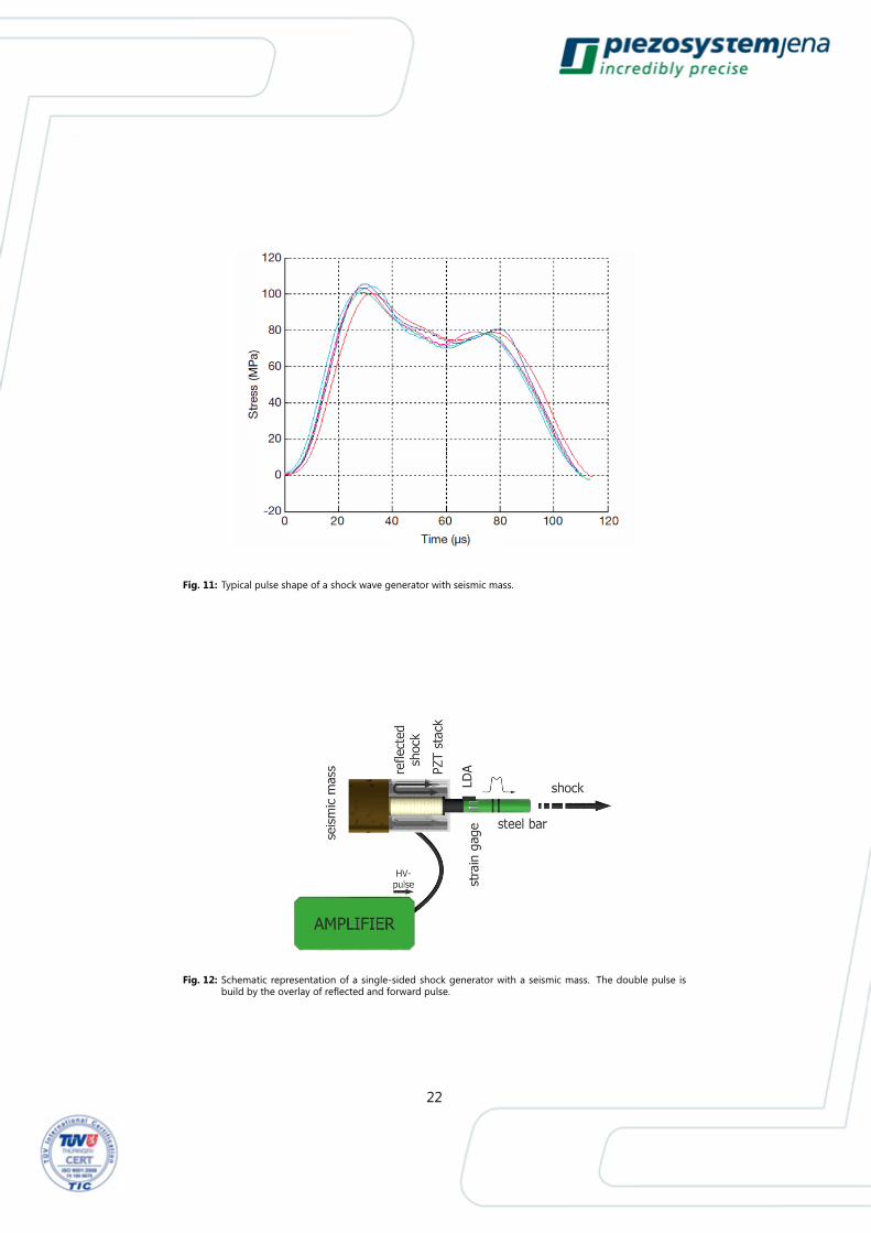
Fig. 11: Typical pulse shape of a shock wave generator with seismic mass.
Fig. 12: Schematic representation of a single-sided shock generator with a seismic mass. The double pulse isbuild by the overlay of reflected and forward pulse.
22

4.5 Electrical driving of piezo shock-wave generators
Piezo shock-wave generators are similar to capacitors. By a high current their
capacitance will be charged. Because of the piezo electric coupling a mechan-
ical shock is generated. The basic aim is the generation of high shock energy,
therefore a high volume of the actuator and a special, high dielectric ceramic
material is necessary. Therefore the energy content of the shock only depends
on the electrical driving conditions. Piezo-electrical shock-wave generators typ-
ical have a capacitance of ≈ 10 µF (low-level signal).
A capacitance of 10 µF under a resistance of 1 Ω has a charging time constant of
RC = 10 µs. Thereby the electrical rise time is shorter than the pulse width given
by the actuators dimensions. To charge a actuator to a voltage of U0 = 800 V a
maximum current of U0/R = 800 A is needed. The capacitor takes the charge
Q = C · U0 = 8 · 10−3 Coulomb and the energy 1/2 · C · U20 = 3.6 J. These
are approximate values because the large-signal behavior must be considered.
In particular in the so called semi bipolar operation the energy density can be
twice as high.
The electrical current is generated by a high power transistor switch as shown
in figure 13. A capacitor bank is charged to the selected voltage (typical up to
+800 V). At unipolar operation the piezo stack is discharged before the shock. At
semi bipolar operation the actuator is charged with negative voltage to -200 V
by a separate power supply. In this case the voltage pulse amounts 1000 V. Be-
cause of nonlinearities of the ceramic material the pulse power is 50% higher
instead of 25%. After the shock the actuator will be discharged by a larger re-
sistor (typ. 50 Ω, RC = 0.5 ms). After that the actuator is charged negative for
the next pulse.
With the sufficient power of the amplifier pulse repetitions to 100 Hz are possi-
ble. Because of the limited cooling of the actuators high repetition rates should
be done in burst-mode.
23

Fig. 13: Semi bipolar control by high voltage pulser. The switch with tree settings represents a combination ofhigh power transistors, which are driven by a logic device. 1. Negative charging to -200 V, 2. Shock likecharging to +800 V, 3. Discharge to 0 V.
4.6 Outlook
The parameters of piezo-electrical ceramic stacks (blocking pressure, energy
density and so on) are independent of the actuators dimensions. Therefore ef-
ficient piezo-electrical shock-wave generators are scalable in size, configuration
and range of performance in a wide range. They reach from miniature sizes
trough to high volume shock generators. Based on the high reproducibility
and potential high repetition rates, piezo shock generators are particularly use-
able for realistic dynamic load tests of components under high accelerations.
Thereby they beat common shaker arrangements.
Piezo electric shock-wave generators more and more replace the shaker mea-
surement technology in the field of modal analysis. They are ideally suited for
systematic generation of acceleration profiles with high dynamics. Therefore
they are the first class for the calibration of shock and impact sensors. The pre-
cise triggering in microsecond range allows the arrangement of multiple shock-
wave generators in phased arrays, to generate variable shock fronts. It is pos-
sible to synchronize the shock with other fast physical processes. Piezo shock
generators are fit for permanent integration (e.g. to cast into materials) at inac-
cessible areas.
By inverting the operational state piezo-actuators are able to compensate/damp
24

shocks and vibrations.
4.7 Theory of the bar shock
Impact propagation in the ideal bar
The ideal bar is thin compared to its length. According to the mathematical
approach of d'Alembert for the solution of the wave equation, a shock-wave
propagates through the ideal bar to both sides without dispersion. A short
term change in compression is referred to as a shock or shock-wave to distin-
guish it from harmonic waves.
The bar theory can be applied for the propagation of shock-waves in thin bars.
If a shock is triggered at one end of a homogenous bar with the cross section
A this shock will be propagate unchanged with sonic velocity in longitudinal di-
rection. The sonic velocity c equals:
c =
√E
ρ
Synchronously to the elastic pulse a velocity pulse of the particles (particle ve-
locity) propagates through the bar at sonic velocity. The particle velocity is ac-
cording to:
σ(t) = −I · v(t)
This is nothing other than to use the principle of linear momentum at the bar
with the so called acoustic impedance I.
I = ρ · c
The algebraic sign determines the direction of the shock. Hooke's law
σ = E · ε
combines the mechanical stress σ with the elongation ε . It is fundamental that
potential and kinetic energy coexist equally and don’t exchange each other
except at the end of the bar and during changes in cross section and/or the
25

impedance. A harmonic wave is characterized by the sinusoidal, harmonic en-
ergy exchange between kinetic and potential energy, this is an important dif-
ference with the shock impulse.
In general two shock impulses spread to the right and to the left independently
from each other. The mechanical stress at location x at the time t results in:
σ(x,t) = σr(x− ct,t) + σl(x+ ct,t)
shock propagation in the bar with the sonic velocity c. The bar is thus an ideal
conductor of the impact sound.
For the corresponding particle velocity
v(x,t) =1
I· (σr(x,t)− σl(x,t))
is true. The impedance of the bar for steel is approximately 4 · 107 kg ·m−2 · s−1.
The principle of linear momentum may also be interpreted as the first inte-
gral of the equation of motion. At σ = 200 MPa the particle velocity reaches
≈ 5 m · s−2. The impact energy is transported one half elastic and one half
kinetical. The impact energy is calculated with
W =A
2 · I·∫ T
0
σ2(t)dt
from the time profile of the stress or also the time profile from particle velocity.
A is the cross-section of the bar. In this case the two measurement techniques
for detecting the impact energy by strain gauges and laser Doppler velocity
measurement LDA are different.
W =A · I2
·∫ T
0
v2(t)dt
On the one hand the impact of the bar is generated by an impulse, on the
other hand it is transmitted through the bar and gets effective at the other end
depending on the boundary conditions. For the transported momentum p it is
26

valid:
p = A ·∫ Timpulse
0
σ(t)dt
If the end is acoustically non-reverberant (sound-absorbent) the tension does
change the sign, the particle velocity does not. Is the end acoustically hard (ide-
ally clamped), the particle velocity does change its sign the tension does not.
While in an infinitely long bar elastic and kinetic energy are equal, the energy
at the bar end is completely elastic (hard end) or completely kinetic (free end).
The integration limits must be considered in the calculation.
If the cross-section of the bar changes from A1 to A2, then simple laws of trans-
mission (τ ) and reflection (r) for the tension are valid (and analog for the particle
velocity).
τ = 2 · A1
A1 +A2
r =A2 −A1
A1 +A2
If the characteristic impedance changes at the interface from impedance I1 to
I2, it is true:
τ = 2 · I2I1 + I2
r =I2 − I1I1 + I2
For simultaneous change of the cross-section and impedance, the equations
are:
τ = 2 · A1 · I2A1 · I2 +A2 · I2
r =A2 · I2 −A1 · I1A1 · I1 +A2 · I2
In general, stress pulses spread independently in both longitudinal directions
of the bar. Furthermore, they can interfere at a defined location resulting in a
superposition of the single pulses. This also holds for the particle velocity in the
same way.
27

The limits of the bar theory are reached, when the transverse propagation can't
be neglected and no planar stress state is existent.
Impulse generation by a ramming bar
An impulse can be generated by impacting two cylindrical, bar-shaped bodies.
This impulse is the same as in mining equipment by air piston, ram and tool
shank. The contact surfaces are relatively slightly spherical, so that we can take
the”Hertzian contact theory“ as a basis. The collision of two cylinders with ideal
planar surfaces can either be viewed as a border case of the Hertzian contact
with very large radii or must be solved with an acoustic approach.
The index 1 refers to bar 1, 2 to bar 2. The effective Young's modulus Eeff is
given by:
Eeff =1− ν21E1
+1− ν22E2
The effective radius of the contact surfaces with the radii R1 and R2:
1
Reff=
1
R1+
1
R2
With Eeff and Reff a force constant k is calculated by Hertz:
kHertz =4
3· Eeff ·R
12
eff
With this, the contact force is a function of the penetration of the contact sur-
faces w in the static case:
Fk(w) = kHertz · w32
In the dynamic Hertzian contact between body 1 and 2 applies to the effective
mass meff:1
meff=
1
m1+
1
m2
and the dynamic force:
Fk(w(t)) = kHertz · w32 (t)
28
For the duration of the contact Tcontact applies:
Tcontact = 2.9432 ·(15
16
) 25
· 1
E25
eff
·m25
eff · 1
R15
eff
· 1
v15
The free flying bar can be described with two virtual tension pulses σl and σr
(same magnitude but opposite algebraic sign)
σ0 =I · v02
The resulting particle velocity is:
v0 =1
I · (σr − σl)
During the shock of the bar (hammer head or air piston) energy andmomentum
are transmitted to the bar with sonic speed.
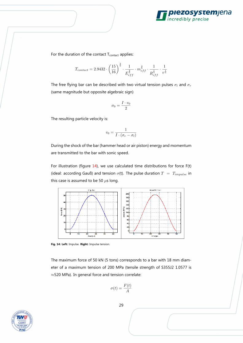
For illustration (figure 14), we use calculated time distributions for force F(t)
(ideal: according Gauß) and tension σ(t). The pulse duration T = Timpulse in
this case is assumed to be 50 µs long.
Fig. 14: Left: Impulse. Right: Impulse tension.
The maximum force of 50 kN (5 tons) corresponds to a bar with 18 mm diam-
eter of a maximum tension of 200 MPa (tensile strength of S355J2 1.0577 is
≈520 MPa). In general force and tension correlate:
σ(t) =F (t)
A
29

Newton’s second law links the temporal integral of the force with the change of
the momentum ∆p to the impulse:
∆p =
∫ T
0
F (t)dt
This momentum can be related to a mass according to:
∆p = m ·∆v
The change in momentum of 1.3 kg ·m · s−1 corresponds to a change of the
particle velocity.
A good approximation of a Gaussian pulse is given by:
σ = σ0 · sin(π · tT
) 32
Thus, the energy can be calculated analytically:
W =4 · T ·A · σ2
0
3 · π · I
The momentum p cannot be calculated analytically.
It should be noted that the shock and a single harmonic oscillation do not
match. You need a temporal and spatial Fourier distribution.
A forth and back going shock pulse only shares the frequency with a resonant
oscillation, but not the mechanical stress distribution in the bar.
The piezo-electric actuator as a dormant bar
We distinguish the direct from the inverse piezo-electric effect (discovered in
1880 by the Curie brothers at quartz crystals). In the direct piezo-electrical ef-
fect a polarization is produced by an external force. The direct piezo-electric
effect applies in sensor applications.
The inverse piezo-electric effect is characterized by a mechanical strain ε gen-
30
erated by an electric field Eel. Represented by the equation of state:
ε = cE · σ + d33 · Eel
cE is the elastic constant at a constant electric field strength (e.g. Eel = 0). d33 is
the piezo-electric charge constant in the longitudinal (axial) direction of expan-
sion. If no mechanical stress is generated, i.e. reign free boundary conditions,
the expansion of the electric field strength is proportional to the elongation. If
the elongation is blocked, the result is a mechanical stress.
σ = −d33 · Eel
cE
This stress is negative (compressive stress). This equation is the basis for piezo-
electric shock generation.
Since the shock generation in the bar is made directly the bar is called active
bar.
If a stack of parallel contacted piezo discs is instantly driven by an electrical volt-
age, the active bar gives two shock impulses pr and pl. These shock impulses
have the same absolute value p0 and the same sign, but traveling into different
directions. For the impact energy it holds:
Wo =1
2· Vpiezo · Epiezo · d233 · E2
el
Vpiezo represents the volume of the actuator, Epiezo the Young's modulus of the
actuator.
In reality, the input signal, due to its limited rising time, must be convolved with
the mechanical voltage impulse. The otherwise ideal square pulse is rounded.
31

Nomenclature
Symbol Declaration Unit
A Cross section m2
c Sonic velocity m · s−1
cF Spring stiffness N · cm−1
cT Actuator stiffness N · µm−1
cE Elastic constant at constant electric field m2 ·N−1
d Thickness of a single ceramic disc µm
d33 piezo-electric strain coefficient for the longi-
tudinal effect
m · V−1
E Young's modulus N ·m−2
Eel Electric field V ·m−1
ε Elongation -
F Force N
I Acoustical field impedance kg ·m−2 · s−1
l0 Elongation without external force µm
m Mass kg
ν Poisson ratio -
p Momentum N · s
R Radius m
r Reflection coefficient -
ρ Density g · cm−3
σ Mechanical stress N ·m−2
T Pulse duration s
τ Transmission factor -
U Electrical voltage V
V Volume m3
v Particle velocity m · s−1
W Energy J
w Bend m
32