piezo actu ator drive -...
TRANSCRIPT
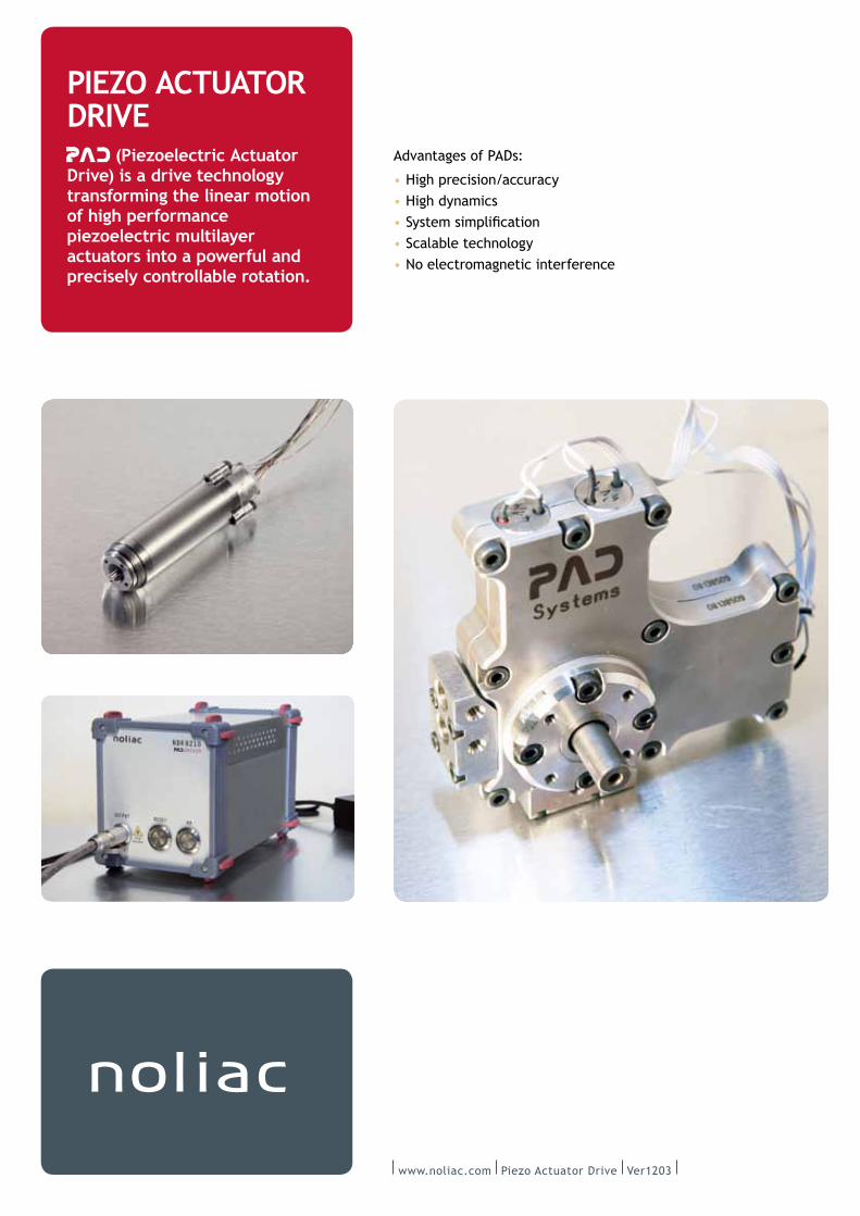
Advantages of PADs:
High precision/accuracy
High dynamics
Scalable technology
No electromagnetic interference
www.noliac.com Piezo Actuator Drive Ver1203
PIEZO ACTUATOR DRIVE
(Piezoelectric Actuator Drive) is a drive technology transforming the linear motion of high performance piezoelectric multilayer actuators into a powerful and precisely controllable rotation.
www.noliac.com Piezo Actuator Drive Ver1203 2
PIEZO ACTUATOR DRIVE Applications
Medical devices
Surgical robots/biopsy robots
Treatment tables for Magnetic Resonance
Imaging (MRI)
Fluid management in fusion/insulin pumps
Mammography
Automation
Precision valves
Positioning drives
Pick and Place Automation
Microdosing systems
Rotary modules for robots
Micro production and assembly
Extreme condition remote handling
Robotics
Personal assistants for handicapped
people
High precision welding robots
Human machine interface with force
feedback
Aviation/Military
Servo valve/Electro-‐hydraulic actuator
Flight control surface actuation
Positioning/ adjustment of surveillance
of reconnaissance systems
Antenna adjustment
Automotive
Camshaft adjustment
Exhaust Gas Recirculation (EGR)
Adaptive spoiler
Weight compensated trunk deck
Seat adjustment/window lifters
Variable Valve Timing (VVT)
Optics
Beam steering
Adaptive optics

www.noliac.com Piezo Actuator Drive Ver1203 3
PIEZO ACTUATOR DRIVE Introduction
Siemens AG initiated the development of the PAD technology from
of piezo technology for commercialization of the technology was
needed. Noliac was selected to acquire the PAD technology in
2010. The transaction included more than 20 patent families, fully
equipped laboratories, PAD prototypes, demonstrators and training
of engineers.
Since then, extensive work by the skilled Noliac engineers has
industrial partners.
SIGNIFICANT IMPROVEMENTSAmong many improvements, Noliac has developed a special
drive and making assembly easier as the number of parts thus was
decreased from 29 to 19 parts. Also, this design makes it possible
housing, which is preferred because it facilitates the replacement
of existing motors in the market.
Further, new shapes of the micro-‐toothing have been designed
with the effect of optimizing performance.
OVERCOMING ELECTROMAGNETIC MOTOR LIMITATIONSWithin industrial, medical, and robotic application areas,
powerful, precise and small electrical drives coupled with
sensing capabilities are becoming increasingly important.
Mechatronic system solutions are strongly recommended as the
tasks become more and more complex and high-‐level integration
of encoders, gearbox, mechanics, sensors and electronics is
becoming mandatory. As a result of these requirements, there is
increasing interest towards piezoelectric drives, which are able to
overcome some of the limitations of conventional electromagnetic
motor drives by utilizing the smart sensor/actuator properties
of piezoelectric materials. Moreover, due to the direct acting
principle, piezoelectric motors in general do not necessarily
require a gearbox. Thus, weight, size and complexity may be
OPEN-‐LOOPED AND STRONGLY SYNCHRONIZEDAs PAD is open-‐loop controlled, PADs can be strongly synchronized
to each other, allowing the PAD to be perfectly suited for robotic
applications. In this context, a Delta-‐3 robot has been designed
to prove its capabilities. A common FPGA synchronously drives
ensures that the Delta-‐3 robot not only shows very high resolution,
but also is capable of high repeatability.
Figure A: Delta-‐3 Robot Design.

www.noliac.com Piezo Actuator Drive Ver1203 4
PIEZO ACTUATOR DRIVE Technology
The principle of the PAD technology rests upon the conversion
of the periodic elongation of powerful multilayer actuators into
precise rotation of a motor shaft. To improve the performance
of the PAD even further, a newly developed micromechanical
interlock between the motor ring and the motor shaft was
applied, increasing torque and precision while avoiding backlash
and slippage.
The approach, as shown in Figure B, is an arrangement of two
orthogonally orientated piezo multilayer stacks directly attached
to a motor ring covering a motor shaft, the diameter of the shaft
being slightly smaller than the internal diameter of the ring.
Thanks to the innovative design, the PAD drive uses very few
components compared to servo-‐controlled drive systems, allowing
a more straightforward, compact and reliable design.
Piezo actuatorPreload spring
WeldingMount
Joint
Motor shaftMotor ring
Kinematics principle with microtoothing
Figure B: New approach transforming linear movement into
controllable rotation.
Figure C: Assembly parts and prototype.
Bottom mount
Tube spring
Piezo multilayer actuator
Top mount
Motor ring
Motor shaft
Bearing
Motor housing
www.noliac.com Piezo Actuator Drive Ver1203 5
PIEZO ACTUATOR DRIVE Features
Due to the properties of piezo components and the innovative
design the piezo actuator drive offers, considerable advantages in
terms of precision, dynamics, torque/ load sensing and scalability
are prevailing.
Additionally, similarly to the Noliac state-‐of-‐the-‐art multilayer
piezo components, the PAD is capable of operating under extreme
PRECISION
(<2 arc seconds) without encoders/decoders
DYNAMICS
(low inertia)
TORQUE/LOAD SENSING
SCALABILITY
OTHERS
or UHV
As the piezoelectric effect not only enables actuation, but also
provides sensor capabilities in parallel, the PAD is capable of
delivering real time torque measurement with high sensitivity,
which allows a very compact drive system design.
Due to the adaptability of the kinematic principle, the PAD
technology is perfectly scalable in terms of size, power, actuators,
materials and number of drives.

www.noliac.com Piezo Actuator Drive Ver1203
PIEZO ACTUATOR DRIVE Features
Motor types Problems/Limitations PAD Characteristics
DC/EC Motor
energy
introduces backlash
applications
Servo Motors
positioning
encoder
temperatures
Stepper Motors
positioning
information
occur
Piezo Motors
encoder
and torque (1 Nm)
possible including smart load sensing
All above Characteristics are highly dependent on
temperature and humidity
LIMITATIONS ON EXISTING DRIVE SYSTEMS COMPARED TO PAD
Although well established throughout applications and markets,
existing conventional motors pose certain limitations and
sometimes problems that may be overcome with the PAD
technology. Table A lays out the generic limitation and problems
to be encountered with existing motor and drive systems, while
the PAD technology characteristics are set against the limitations:
State-‐of-‐the-‐Art piezoelectric motors are all
based on discontinuous operating principles
(either resonant or non-‐resonant). By
subsequent elongation of a few microns of the
actuator, macroscopic motion is achieved. Yet,
these friction based approaches continuously
lead to small, self blocking piezoelectric
drives which limitations are set by slippage,
backlash, wear and restricted reliability.

www.noliac.com Piezo Actuator Drive Ver1203 7
PIEZO ACTUATOR DRIVE Reliability and service life
Since internal forces in the PAD motors are comparatively low,
and all structures have to be very rigid to reduce elasticity,
most parts are rather oversized and will survive longer than
ever needed. The two most critical parts are the actuators
and the toothing. However, the actuators in the prototypes are
made for more than 3x10⁹ load cycles, which in case of the PAD
corresponds to about 3000h operation at full speed (which only
occurs in applications where PADs are not the obvious choice).
test bench and subjected to more than 107 load changes,
and no breaking of teeth was observed due to the low
surface pressure and the large number of teeth.
TYPICAL OPERATING RANGE OF PAD7200Torque (Nm)
Rotation speed (rpm)
torque d
epends o
n load
TOOTH GEOMETRY
pitch): 38 µm
Shaft
Figure D: Shaft enlargement and tooth geometry.
SCALABLE TECHNOLOGY
Figure F: The PAD is a scalable technology.
Torque (Nm)
Size
5.0
0.10
0.010
Application of
piezo multilayer
stack actuators
Application of
bending actuators
PAD7100
PAD7200
arbitrary rotation speed
Sr Smax
Tr
Continuousoperation
Intermittentoperation
www.noliac.com Piezo Actuator Drive Ver1203 8
PIEZO ACTUATOR DRIVE The PAD family
Noliac’s range of PADs is based upon different models granting our
customers a broad variety of performances, sizes and designs.
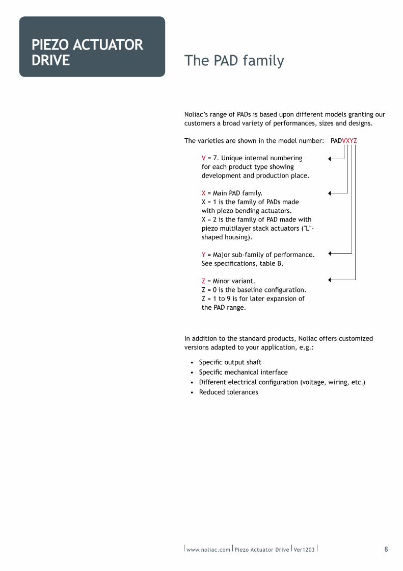
The varieties are shown in the model number: PADVXYZ
In addition to the standard products, Noliac offers customized
versions adapted to your application, e.g.:
V = 7. Unique internal numbering
for each product type showing
development and production place.
X = Main PAD family.
X = 1 is the family of PADs made
with piezo bending actuators.
X = 2 is the family of PAD made with
shaped housing).
Y = Major sub-‐family of performance.
Z = Minor variant.
Z = 1 to 9 is for later expansion of
the PAD range.
www.noliac.com Piezo Actuator Drive Ver1203 9
PIEZO ACTUATOR DRIVE
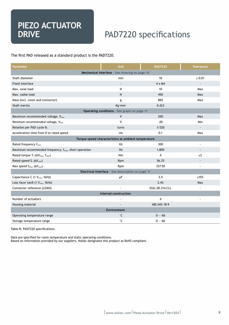
Parameter Unit PAD7220 Tolerances
Mechanical interface – See drawing on page 10
Shaft diameter mm 10 ± 0.01
Fixed interface -‐ 4 x M4 -‐
Max. axial load N 10 Max
Max. radial load N 450 Max
Mass (incl. cover and connector) g Max
Shaft inertia Kg.mm2 0.423
Operating conditions – See graph on page 11
Maximum recommended voltage, Vmax V 200 Max
Minimum recommended voltage, Vmin V -‐20 Min
C turns 1/320 -‐
Acceleration time from 0 to rated speed ms 0.1 Max
Torque-‐speed characteristics at ambient temperature
Rated frequency fnom Hz 300 -‐
Maximum recommended frequency, fmax, short operation Hz 1,800 -‐
Rated torque Tr (@Vmax, fnom) Nm 4 ±2
Rated speed Sr (@fnom) Rpm -‐
Max speed Smax (@fmax) Rpm 337.50 -‐
Electrical interface – See description on page 11
Capacitance C (1 Vrms, 1kHz) 3.5 ±15%
rms, 1kHz) 2.4% Max
-‐ -‐
Internal construction
Number of actuators -‐ 4 -‐
Housing material -‐ X8CrNiS 18-‐9
Environment
°C
Storage temperature range °C
Based on information provided by our suppliers, Noliac designates this product as RoHS compliant.
www.noliac.com Piezo Actuator Drive Ver1203 10
PIEZO ACTUATOR DRIVE PAD7220 interfaces
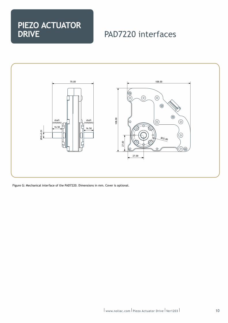
Figure G: Mechanical interface of the PAD7220. Dimensions in mm. Cover is optional.
shaft
(rotates)
16.5016.50
shaft
(rotates)
Ø10±0.01
Ø32.00
108.00
108.0070.00
27.00
27.00
www.noliac.com Piezo Actuator Drive Ver1203 11
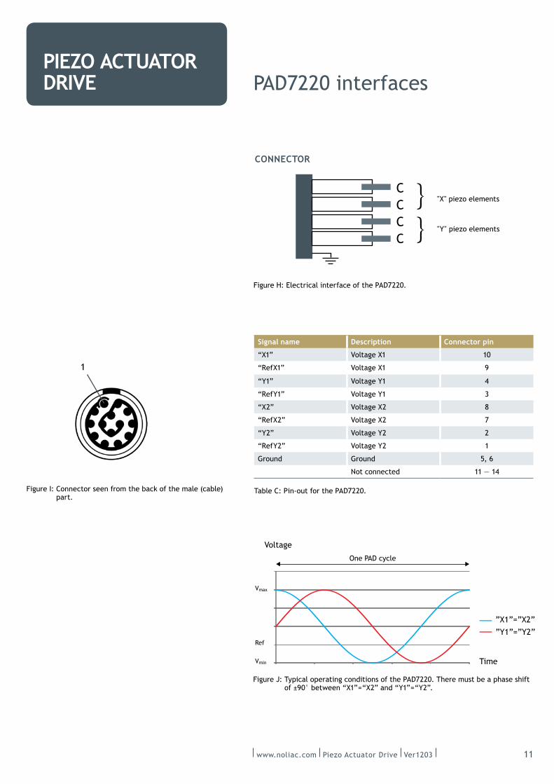
PIEZO ACTUATOR DRIVE PAD7220 interfaces
of ±90° between “X1” = “X2” and “Y1” = “Y2”.
Voltage
Vmin
Vmax
Ref
Time
”X1”=”X2””Y1”=”Y2”
One PAD cycle
Signal name Description Connector pin
“X1” Voltage X1 10
“RefX1” Voltage X1 9
“Y1” Voltage Y1 4
“RefY1” Voltage Y1 3
“X2” Voltage X2 8
“RefX2” Voltage X2 7
“Y2” Voltage Y2 2
“RefY2” Voltage Y2 1
Ground Ground
Not connected 11 — 14
Table C: Pin-‐out for the PAD7220.
CONNECTOR
C
C
C
C
}}
"X" piezo elements
"Y" piezo elements
Figure H: Electrical interface of the PAD7220.
Figure I: Connector seen from the back of the male (cable)
part.
1
www.noliac.com Piezo Actuator Drive Ver1203 12
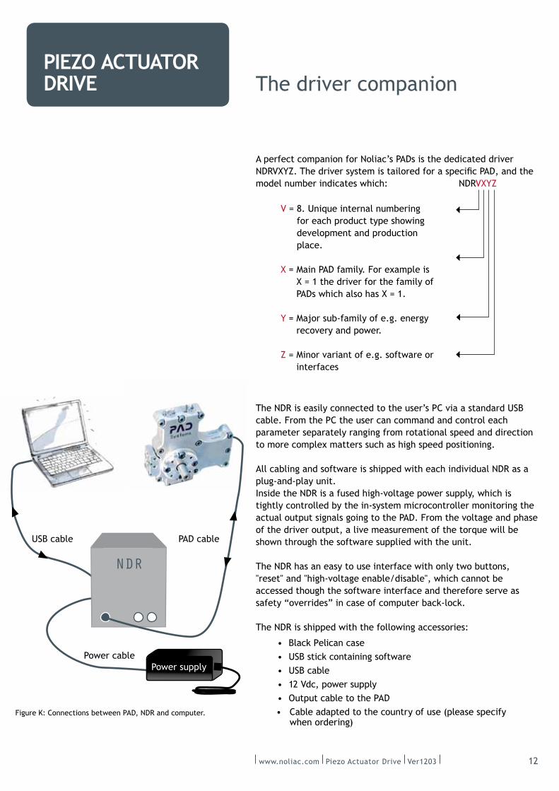
PIEZO ACTUATOR DRIVE The driver companion
A perfect companion for Noliac’s PADs is the dedicated driver
model number indicates which: NDRVXYZ
V = 8. Unique internal numbering
for each product type showing
development and production
place.
X = Main PAD family. For example is
X = 1 the driver for the family of
PADs which also has X = 1.
Y = Major sub-‐family of e.g. energy
recovery and power.
Z = Minor variant of e.g. software or
interfaces
The NDR is easily connected to the user’s PC via a standard USB
cable. From the PC the user can command and control each
parameter separately ranging from rotational speed and direction
to more complex matters such as high speed positioning.
All cabling and software is shipped with each individual NDR as a
plug-‐and-‐play unit.
Inside the NDR is a fused high-‐voltage power supply, which is
tightly controlled by the in-‐system microcontroller monitoring the
actual output signals going to the PAD. From the voltage and phase
of the driver output, a live measurement of the torque will be
shown through the software supplied with the unit.
The NDR has an easy to use interface with only two buttons,
"reset" and "high-‐voltage enable/disable", which cannot be
accessed though the software interface and therefore serve as
safety “overrides” in case of computer back-‐lock.
The NDR is shipped with the following accessories:
Black Pelican case
USB stick containing software
USB cable
12 Vdc, power supply
when ordering)
NDR
Power cable
USB cable PAD cable
Figure K: Connections between PAD, NDR and computer.
Power supply

www.noliac.com Piezo Actuator Drive Ver1203 13
PIEZO ACTUATOR DRIVE
Parameter Unit NDR8210 Tolerances
Input/ output characteristics
Supply voltage Vdc 12
Supply current A 3A Max
Power input connector
USB
Electrical parameters (AC adapter)
Input voltage range Vac 100 — 240
Input frequency range Hz
Power W 80 Max
Operational parameters
V –20 — 200
Frequency range Hz 0 — 40
mV 5 Max
Points per PAD cycle 1,024
Environmental parameters
Temperature range °C +5 — +45
Ingress protection IP 31
Mechanical parameters
Mass kg 1.8 Max
DIMENSIONS
114.7
4.5
124.8
www.noliac.com Piezo Actuator Drive Ver1203 14
PIEZO ACTUATOR DRIVE
PAD and NDR combined
characteristics
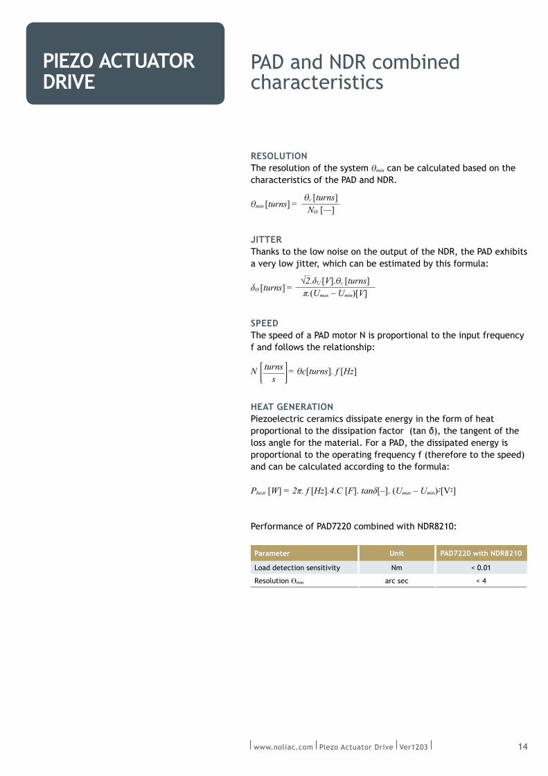
RESOLUTIONThe resolution of the system min can be calculated based on the
characteristics of the PAD and NDR.
min [turns] =
JITTERThanks to the low noise on the output of the NDR, the PAD exhibits
a very low jitter, which can be estimated by this formula:
[turns] =
SPEEDThe speed of a PAD motor N is proportional to the input frequency
f and follows the relationship:
N = c[turns]. f [Hz]
HEAT GENERATIONPiezoelectric ceramics dissipate energy in the form of heat
loss angle for the material. For a PAD, the dissipated energy is
proportional to the operating frequency f (therefore to the speed)
and can be calculated according to the formula:
Pheat [W] [Hz].4.C [F]. [–]. (Umax – Umin)2[V2]
Performance of PAD7220 combined with NDR8210:
Parameter Unit PAD7220 with NDR8210
Nm < 0.01
Resolution min arc sec < 4
c [turns] N [—]
U [V]. c [turns] (Umax – Umin)[V]
turns s
www.noliac.com Piezo Actuator Drive Ver1203 15
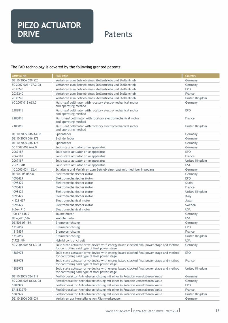
PIEZO ACTUATOR DRIVE Patents
The PAD technology is covered by the following granted patents:
Full Title Country
Verfahren zum Betrieb eines Stellantriebs und Stellantrieb Germany
Verfahren zum Betrieb eines Stellantriebs und Stellantrieb Germany
2033240 Verfahren zum Betrieb eines Stellantriebs und Stellantrieb
2033240 Verfahren zum Betrieb eines Stellantriebs und Stellantrieb France
2033240 Verfahren zum Betrieb eines Stellantriebs und Stellantrieb United Kingdom
Multi-‐leaf collimator with rotatory electromechanical motor
and operating method
Germany
2188815 Multi-‐leaf collimator with rotatory electromechanical motor
and operating method
2188815 Mul ti-‐leaf collimator with rotatory electromechanical motor
and operating method
France
2188815 Multi-‐leaf collimator with rotatory electromechanical motor
and operating method
United Kingdom
Spannfeder Germany
Zylinderfeder Germany
Spannfeder Germany
Solid-‐state actuator drive apparatus Germany
Solid-‐state actuator drive apparatus
Solid-‐state actuator drive apparatus France
Solid-‐state actuator drive apparatus United Kingdom
7,923,901 Solid-‐state actuator drive apparatus USA
Germany
DE 500 08 082.8 Elektromechanischer Motor Germany
1098429 Elektromechanischer Motor
1098429 Elektromechanischer Motor Spain
1098429 Elektromechanischer Motor France
1098429 Elektromechanischer Motor United Kingdom
1098429 Elektromechanischer Motor Italy
4 528 427 Electromechanical motor
1098429 Elektromechanischer Motor Sweden
Electromechanical motor USA
100 17 138.9 Taumelmotor Germany
Wobble motor USA
DE 502 07 189 Bremsvorrichtung Germany
1319859 Bremsvorrichtung
1319859 Bremsvorrichtung France
1319859 Bremsvorrichtung United Kingdom
7,728,484 Hybrid control circuit USA
Germany
1883978
1883978 France
1883978 United Kingdom
DE 10 2005 024 317 Festkörperaktor-‐Antriebsvorrichtung mit einer in Rotation versetzbaren Welle Germany
Festkörperaktor-‐Antriebsvorrichtung mit einer in Rotation versetzbaren Welle Germany
1883979 Festkörperaktor-‐Antriebsvorrichtung mit einer in Rotation versetzbaren Welle
EP1883979 Festkörperaktor-‐Antriebsvorrichtung mit einer in Rotation versetzbaren Welle France
1883979 Festkörperaktor-‐Antriebsvorrichtung mit einer in Rotation versetzbaren Welle United Kingdom
Verfahren zur Herstellung von Räumwerkzeugen Germany