piezo valves vemp€¦ · operation as a proportional 3/3-way valve pressure build-up maintaining...
TRANSCRIPT
Piezo valves VEMP

Subject to change – 2019/052 � Internet: www.festo.com/catalog/...
Piezo valves VEMPKey features
Innovative Versatile Reliable Easy to install
� Piezo technology
� Very low energy consumption
� Very precise
� When combined with pressure
sensor and control electronics it
can be used as a proportional
pressure regulator
� When combined with a flow sensor
and control electronics it can be
used as a proportional flow control
valve
� No self-heating
� Long service life
� Can be mounted on a sub-base or
manifold rail
� Small installation space
� Light weight
-V- New
2019/05 – Subject to change 3� Internet: www.festo.com/catalog/...
Piezo valves VEMPKey features
Mode of operation
Description
1
2
34
5
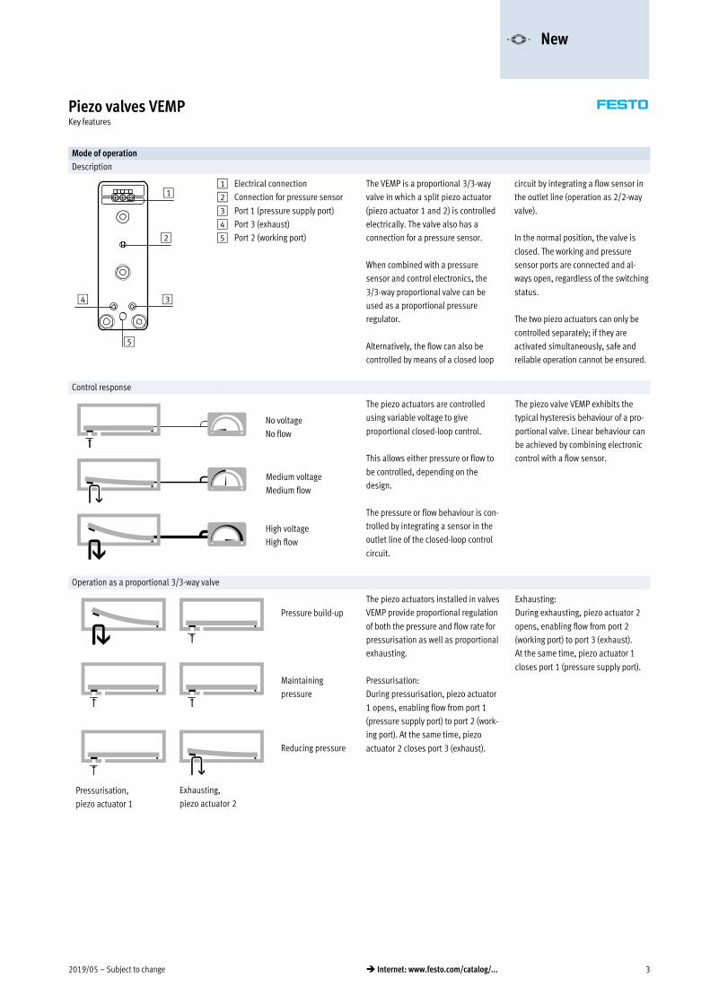
1 Electrical connection
2 Connection for pressure sensor
3 Port 1 (pressure supply port)
4 Port 3 (exhaust)
5 Port 2 (working port)
The VEMP is a proportional 3/3-way
valve in which a split piezo actuator
(piezo actuator 1 and 2) is controlled
electrically. The valve also has a
connection for a pressure sensor.
When combined with a pressure
sensor and control electronics, the
3/3-way proportional valve can be
used as a proportional pressure
regulator.
Alternatively, the flow can also be
controlled by means of a closed loop
circuit by integrating a flow sensor in
the outlet line (operation as 2/2-way
valve).
In the normal position, the valve is
closed. The working and pressure
sensor ports are connected and al
ways open, regardless of the switching
status.
The two piezo actuators can only be
controlled separately; if they are
activated simultaneously, safe and
reliable operation cannot be ensured.
Control response
No voltage
No flow
Medium voltage
Medium flow
High voltage
High flow
The piezo actuators are controlled
using variable voltage to give
proportional closed-loop control.
This allows either pressure or flow to
be controlled, depending on the
design.
The pressure or flow behaviour is con
trolled by integrating a sensor in the
outlet line of the closed-loop control
circuit.
The piezo valve VEMP exhibits the
typical hysteresis behaviour of a pro
portional valve. Linear behaviour can
be achieved by combining electronic
control with a flow sensor.
Operation as a proportional 3/3-way valve
Pressure build-up
Maintaining
pressure
Reducing pressure
Pressurisation,
piezo actuator 1
Exhausting,
piezo actuator 2
The piezo actuators installed in valves
VEMP provide proportional regulation
of both the pressure and flow rate for
pressurisation as well as proportional
exhausting.
Pressurisation:
During pressurisation, piezo actuator
1 opens, enabling flow from port 1
(pressure supply port) to port 2 (work
ing port). At the same time, piezo
actuator 2 closes port 3 (exhaust).
Exhausting:
During exhausting, piezo actuator 2
opens, enabling flow from port 2
(working port) to port 3 (exhaust).
At the same time, piezo actuator 1
closes port 1 (pressure supply port).
-V- New

Subject to change – 2019/054 � Internet: www.festo.com/catalog/...
Piezo valves VEMPKey features
Mode of operation
Operation as a proportional 2/2-way valve
Maximum flow
Valve closed
Low flow
Pressurisation,
piezo actuator 1
Exhausting,
piezo actuator 2
When used as a proportional 2/2-way
valve, only piezo actuator 2 (exhaust)
is switched; piezo actuator 1 (pres
sure supply port) must be electrically
connected to earth (GND).
Flow takes place from port 2 (working
port) to port 3 (exhaust). When used
as a 2/2-way valve, port 1 (pressure
supply port) is not used, and must be
closed.
The flow behaviour is controlled by
integrating a sensor in the supply or
outlet line of the closed-loop control
circuit.
Low energy consumption
Compared with solenoid valves, pro
portional valves with piezo technology
require virtually no energy to maintain
an active state, thanks to their capa
citive principle. The piezo valve oper
ates like a capacitor: it needs current
only at the start in order to charge the
piezoceramics.
No further energy is needed to main
tain its state. The valves therefore
generate no heat. They consume up to
95% less energy than solenoid valves,
which permanently require an
electrical current
-V- New
2019/05 – Subject to change 5� Internet: www.festo.com/catalog/...
Piezo valves VEMPPeripherals overview
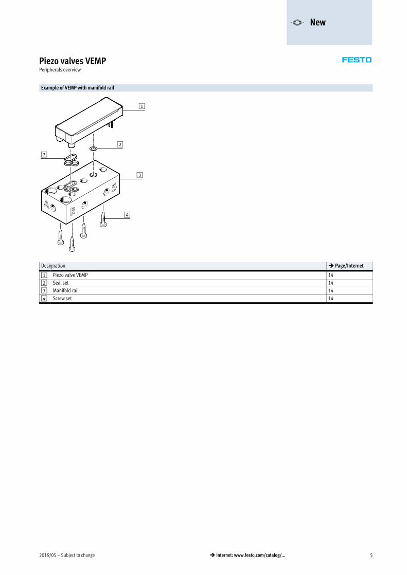
Example of VEMP with manifold rail
1
2
2
3
4
Designation � Page/Internet
1 Piezo valve VEMP 14
2 Seal set 14
3 Manifold rail 14
4 Screw set 14
-V- New

Subject to change – 2019/056 � Internet: www.festo.com/catalog/...
Piezo valves VEMPProduct range overview
Function Description Nominal
width
Flow Operating
pressure
Operating voltage
[l/min] [bar] 0 … 310 V 0 … 250 V
Sub-base valve 3/3-way valve, normally closed, monostable
Flange 1.3 mm 19/20 0 … 1.1 – �
3/3-way valve, normally closed, monostable
Flange 1.3 mm 28/30 0 … 1.7 � –
3/3-way valve, normally closed, monostable
Flange 1.6 mm 18/19 0 … 0.7 � –
3/3-way valve, normally closed, monostable
Flange 1.6 mm 28/27 0 … 1.1 � –
-V- New

2019/05 – Subject to change 7� Internet: www.festo.com/catalog/...
Piezo valves VEMPType codes
VEMP – B S – 3 – – – F – T1 –
Type
VEMP Proportional pressure regulator
Type of directional control valve
B Sub-base valve
Design principle
S Bending actuator
Valve function
3 3/3-way valve, normally closed
Nominal width
13 1.3 mm
16 1.6 mm
Pressure range
D5 0 … 0.5 bar
D7 0 … 1 bar
D19 0 … 1.7 bar
Pneumatic connection
F Flange/sub-base
Operating voltage
22 250 V DC
28 310 V DC
Electrical connection
T1 Pin
Packaging unit quantity
Standard (1 unit)
P30 30 (30 units)
-V- New

Subject to change – 2019/058 � Internet: www.festo.com/catalog/...
Piezo valves VEMPTechnical data
-M- Flow rate
19 … 30 l/min
-P- Voltage
0 … 250 V DC
0 … 310 V DC
-L- Operating pressure
0 … 1.7 bar
General technical data
VEMP-BS-3-13-D7-… VEMP-BS-3-13-D19-… VEMP-BS-3-16-D5-… VEMP-BS-3-16-D7-…
Valve function 3/3-way valve,
monostable
3/3-way valve,
monostable,
2/2-way valve,
monostable
3/3-way valve,
monostable
3/3-way valve,
monostable
Normal position Closed
Standard nominal flow rate 1�2 [l/min] 19 28 18 27
Standard nominal flow rate 2�3 [l/min] 20 29 19 28
Dimensions W x L x H [mm] 17.2 x 52.1 x 7.2
Nominal width [mm] 1.3 1.3 1.6 1.6
Grid dimension [mm] 17.2
Pneumatic connection 1, 2, 3 Flange
Actuation type Electrical
Type of mounting On manifold rail/sub-base
Mounting position Any
Flow direction 1 �2 and 2 �3
Product weight [g] 8
Special characteristics Oxygen-compatible to DIN EN 1797
Electrical data
VEMP-BS-3-13-D7-… VEMP-BS-3-13-D19-… VEMP-BS-3-16-D5-… VEMP-BS-3-16-D7-…
Nominal operating voltage [V DC] 250 310 310 310
Operating voltage range [V DC] 0 … 250 0 … 310 0 … 310 0 … 310
Max. electrical power consumption [mW] 1
Max. current consumption [mA] 5
Max. switching frequency [Hz] 5
Degree of protection Depending on manifold block
-V- New
2019/05 – Subject to change 9� Internet: www.festo.com/catalog/...
Piezo valves VEMPTechnical data
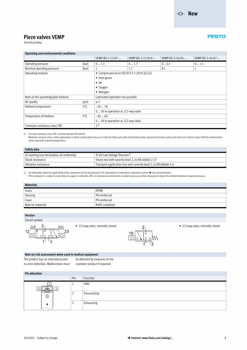
Operating and environmental conditions
VEMP-BS-3-13-D7-… VEMP-BS-3-13-D19-… VEMP-BS-3-16-D5-… VEMP-BS-3-16-D7-…
Operating pressure [bar] 0 … 1.1 0 … 1.7 0 … 0.7 0 … 1.1
Nominal operating pressure [bar] 1 1.7 0.5 1
Operating medium � Compressed air to ISO 8573-1:2010 [6:3:4]
� Inert gases
� Air
� Oxygen
� Nitrogen
Note on the operating/pilot medium Lubricated operation not possible
Air quality [μm] 5
Ambient temperature [°C] –20 … 70
0 … 50 in operation as 2/2-way valve
Temperature of medium [°C] –20 … 60
0 … 50 in operation as 2/2-way valve
Corrosion resistance class CRC 21)
*
1) Corrosion resistance class CRC 2 to Festo standard FN 940070
Moderate corrosion stress. Indoor applications in which condensation may occur. External visible parts with primarily decorative requirements for the surface and which are in direct contact with the ambient atmo
sphere typical for industrial applications.
Safety data
CE marking (see declaration of conformity) To EU Low Voltage Directive1)
Shock resistance Shock test with severity level 2, to EN 60068-2-27
Vibration resistance Transport application test with severity level 2, to EN 60068-2-6
1) For information about the applicability of the component see the manufacturer’s EC declaration of conformity at: www.festo.com/sp � User documentation.
If the component is subject to restrictions on usage in residential, office or commercial environments or small businesses, further measures to reduce the emitted interference may be necessary.
Materials
Seals EPDM
Housing PA reinforced
Cover PA reinforced
Note on materials RoHS compliant
Version
Circuit symbol
� 3/3-way valve, normally closed � 2/2-way valve, normally closed
Note on risk assessment when used in medical equipment
The product has no redundancy and
no error detection. Malfunctions must
be detected by measures in the
customer product if required.
Pin allocation
Pin Function
132 1 GND
2 Pressurizing
3 Exhausting
-V- New

Subject to change – 2019/0510 � Internet: www.festo.com/catalog/...
Piezo valves VEMPTechnical data
VEMPBS313D7F22T1, 1.3 mm nominal width
Flow plotted against operating pressure at 250 V Flow plotted against voltage at room temperature, operating pressure 1 bar
Flow 1 --> 2
Flow 2 --> 3
Flow 1 --> 2
Flow 2 --> 3
VEMPBS313D19F28T1, 1.3 mm nominal width
Flow plotted against operating pressure at 310 V Flow plotted against voltage at room temperature, operating pressure 1.7 bar
Flow 1 --> 2
Flow 2 --> 3
Flow 1 --> 2
Flow 2 --> 3
-V- New
2019/05 – Subject to change 11� Internet: www.festo.com/catalog/...
Piezo valves VEMPTechnical data
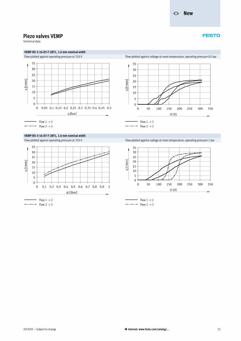
VEMPBS316D5F28T1, 1.6 mm nominal width
Flow plotted against operating pressure at 310 V Flow plotted against voltage at room temperature, operating pressure 0.5 bar
Flow 1 --> 2
Flow 2 --> 3
Flow 1 --> 2
Flow 2 --> 3
VEMPBS316D7F28T1, 1.6 mm nominal width
Flow plotted against operating pressure at 310 V Flow plotted against voltage at room temperature, operating pressure 1 bar
Flow 1 --> 2
Flow 2 --> 3
Flow 1 --> 2
Flow 2 --> 3
-V- New

Subject to change – 2019/0512 � Internet: www.festo.com/catalog/...
Piezo valves VEMPTechnical data
Dimensions Download CAD data � www.festo.com
Type B1 B2 B3 B4 B5 B6 B7 B8 D1
D2
D3
D4
D5
VEMP 17.2 8.1 11.4 6.4 5.7 3.2 5.1 2.5 4.4 2 2.5 1.3/1.6 2.5
Type H1 H2 H3 H4 L1 L2 L3 L4 L5 L6 L7 L8 L9 L10 L11 T15
VEMP 7.2 4.3 11.6 5 52.1 9.8 12.1 3.4 3 5.6 26.3 20.3 19.5 17.4 0.6 4.8
-V- New
2019/05 – Subject to change 13� Internet: www.festo.com/catalog/...
Piezo valves VEMPTechnical data
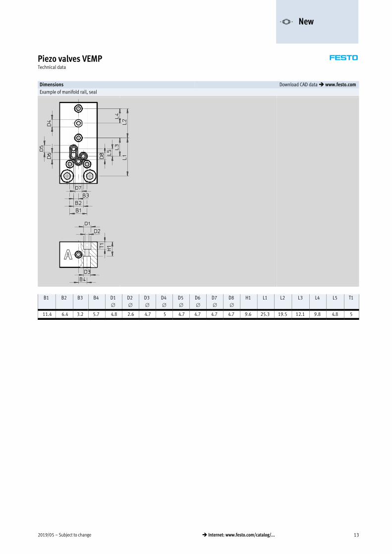
Dimensions Download CAD data � www.festo.com
Example of manifold rail, seal
B1 B2 B3 B4 D1
D2
D3
D4
D5
D6
D7
D8
H1 L1 L2 L3 L4 L5 T1
11.4 6.4 3.2 5.7 4.8 2.6 4.7 5 4.7 4.7 4.7 4.7 9.6 25.3 19.5 12.1 9.8 4.8 5
-V- New
Subject to change – 2019/0514 � Internet: www.festo.com/catalog/...
Piezo valves VEMPAccessories
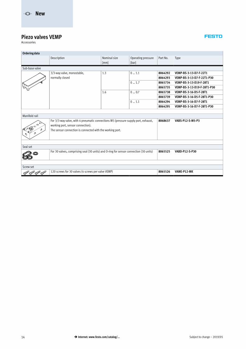
Ordering data
Description Nominal size Operating pressure Part No. Type
[mm] [bar]
Sub-base valve
3/3-way valve, monostable,
normally closed
1.3 0 … 1.1 8064292 VEMP-BS-3-13-D7-F-22T1
8064293 VEMP-BS-3-13-D7-F-22T1-P30
0 … 1.7 8065734 VEMP-BS-3-13-D19-F-28T1
8065735 VEMP-BS-3-13-D19-F-28T1-P30
1.6 0 … 0.7 8065738 VEMP-BS-3-16-D5-F-28T1
8065739 VEMP-BS-3-16-D5-F-28T1-P30
0 … 1.1 8064294 VEMP-BS-3-16-D7-F-28T1
8064295 VEMP-BS-3-16-D7-F-28T1-P30
Manifold rail
For 3/3-way valve, with 4 pneumatic connections M5 (pressure supply port, exhaust,
working port, sensor connection).
The sensor connection is connected with the working port.
8068637 VABS-P12-S-M5-P3
Seal set
For 30 valves, comprising seal (30 units) and O-ring for sensor connection (30 units) 8065525 VABD-P12-S-P30
Screw set
120 screws for 30 valves (4 screws per valve VEMP) 8065526 VAME-P12-MK
-V- New

Festo - Your Partner in Automation
www.festo.com
Connect with us
www.festo.com/socialmedia
1 Festo Inc. 2 Festo Pneumatic 3 Festo Corporation 4 Regional Service Center
5300 Explorer DriveMississauga, ON L4W 5G4Canada
Av. Ceylán 3,Col. Tequesquináhuac54020 Tlalnepantla, Estado de México
1377 Motor ParkwaySuite 310Islandia, NY 11749
7777 Columbia RoadMason, OH 45040
Festo Customer Interaction CenterTel: 1 877 463 3786Fax: 1 877 393 3786Email: [email protected]
Multinational Contact Center01 800 337 8669
Festo Customer Interaction Center1 800 993 37861 800 963 3786
Subj
ect t
o ch
ange