s bhat prod con2009
TRANSCRIPT

1
Corrosion Resistant Alloy (CRA)-Carbon Steel Combination (Hybrid)
Material of Construction (MOC) strategy of
Well Completion For Severe Corrosive
Oil & Gas Field Development
Presented By: Subrahmanya BhatMaterials & Corrosion Section
Institute of Engineering & Ocean TechnologyOil and Natural Gas Corporation Limited

2
Outline of Presentation
Background Description of Problem Approach of Analysis
Identification of technologies and solution: Evolution of the options: Summary and Recommendations
2

3
BackgroundSevere Down Hole Corrosion In ONGC Fields
B-193 marginal field – B&S Asset –Western offshore : H2S : 40000 ppm - HSE issue: Wrong MOC – failure - few hours - through cracking, 1000ppm H2S leak : fatal
In –situ- Combustion – EOR : Santhal & Balol Pilot air injection – EOR for Gamij, Ahmedabad Injector wells : High Temp – Oxidation 450 -500°C : Santhal & Balol (heavy oil) 350°C : Gamij, Ahmedabad (light oil) HSE issue: Casing failure – internal blow out/bypass to
near surface tube well water reservoir-pollution complication
3

4
Profitability of hydrocarbon exploitation
CAPEX - conduits, containment vessels and process equipments.
OPEX - process costs Cost of conduits, containment vessels, and
process equipments depends on MOC.Optimize MOC with process control -
reduce total cost of production. Facilitate sustained profitability without
Sacrificing HSE issues.
4

5
MOC - current study
Well completion: Casing, tubing, packer for high sour oil & gas wells
Well completion : Casing, tubing, packer for injector wells of in-situ combustion scheme of EOR
5

6
Sour oil & gas : Marginal field development(Bassein & Satellite Asset)
B-193 cluster: B-193, B-178 , B-172, B-179,B-28-A,B-23-A, B-28 & B-180 fields:
H2S(40000 ppm) CO2 (4 -11%) In-place oil : 20.86 MMt B-22 cluster - B-22, BS-12, BS-13, B-149-1,
B-149-3 fields : CO2 gas (5%) H2S (230ppm) In place oil : 10 MMT & gas : 10.02 BCM Location- Heera-Panna-Bassein block 60-90km - from Mumbai citywater depth : 70m
6

7
B-193 : Bassein Formation : Corrosion Severity
Parameters Oil Wells Gas Well (B-28-2)
p-CO2, psi 87 -190 172
p -H2S, psi 27 - 111 86
Ratio of p -CO2/ p -H2S 2 – 3.2 2
pH 3.3 – 3.6 3.3
BHT, °C 91 - 136 133
Cor.rate, mm/y 4.5 – 20.6 33.4
7

8
B-193 : Mukta Formation: Corrosion Severity Parameters Oil Wells Gas Wells
p-CO2, psi 28 - 80 40 – 88
p -H2S, psi 0.4 - 46 2.6 - 29
Ratio of p -CO2/ p -H2S 1.3 -80 2.2 - 104
pH 3.6 – 3.9 3.6 – 3.7
BHT, °C 101 - 120 133
Cor.rate, mm/y 2 – 6 4.44 - 19.2
8

9
B-193 : Panna Formation: Corrosion Severity
Parameters Oil Wells Gas Wells
p-CO2, psi 354-367 165 - 551
p -H2S, psi 0.15 0.01 - 0.16
Ratio of p -CO2/ p -H2S 2368 1112 - 11120
pH 3.2 – 3.3 3.2 – 3.3
BHT, °C 145 -162 122 - 158
Cor.rate, mm/y 7.71 -20.7 11.7 - 104.0
9

10
B-22: Corrosion Severity
Parameters Oil Well(B-22-5)
Gas Wells
p-CO2, psi 99 32 - 129
p -H2S, psi 0.46 0.01 – 0.523
Ratio of p -CO2/ p -H2S 215 247 - 3100
pH 3.6 3.6 – 3.9
BHT, °C 90 90-100
Cor.rate, mm/y 1.55 2.32 – 31.6
10

11
Severe Sour Fields of World
Field Temp°C
p-CO2
psi
p-H2S
psi
Salinityg/l
WellsAlloy
Hunield field Oklahoma, USA
140 225 470 <2 N06987,N06625N1027
Big Escambia Creek field, Oklahoma, USA
140 750 140 <2 N06985,N06625N08028,N08825
Offshore south Texas
200 600 450 17 UNS N08028
Labarge Field, Wyoming, USA
140 220 2600 200 N06975
Big Horn filed, Wyoming, USA
220 1050 1800 200 N10276
B-193, India 139 190 111 18.7 Proposed by IEOTN08028
11

12
Guidelines
UK Offshore Industry HSE document, UK NACE, USA API, USA NORSOK, Norway Alberta Energy Utility Board, Canada JNOC Research Center, Japan Nickel Development Institute, Canada
12

13
Standards/Documents for - Sour Service NACE MR0175/ISO15156 (2003) CAPP -Recommended practice for Sour gas,
2003 European Federation Of Corrosion Publication
No 16, Carbon steel, 2002 European Federation Of Corrosion Publication
No. 17, CRA, 2002 Alberta Energy Utility Board Directive,
2008 Materials Selection For Petroleum Refineries
And Gathering Facilities, NACE International
13

14
Approach of analysis Assess severity - design parameters Carbon or low alloy steel suitability Carbon or low alloy steel nonsuitability Corrosion Resistant Alloy suitability Identify CRA CRA as per standards Documentation - Performance of CRA Cor.rate limit - CRA : 0.05mm/y (2mpy) and resistance
to cracking. Take into account Consequence of failure (safety, business loss & environmental damage 1000ppm H2S leak : fatal) Minimize HSE risks & Use Field proven MOC
14

15
Selection Criteria
Mandatory requirements Comply with NACE MR0175, API Design Conditions For new technology ensure greater safetyOperating conditions Mature technologies with history of successful
applicationsDesign temperature Process requirements Special requirements - e.g. Design life
15

16
Corrosion severity grading
Flow dynamics (gas vel <4-6m/s : water hold at bottom, Liquid vel <0.4m/s, higher risk of water wetting)
Temperature & PressureMoisture content pH Chloride, Sulphate & Volatile fatty acids Calcium / Bicarbonate RatioCO2 mole %, H2S PPM Solid Sulphur % partial pressure of CO2 and H2S and their ratio.
16
17
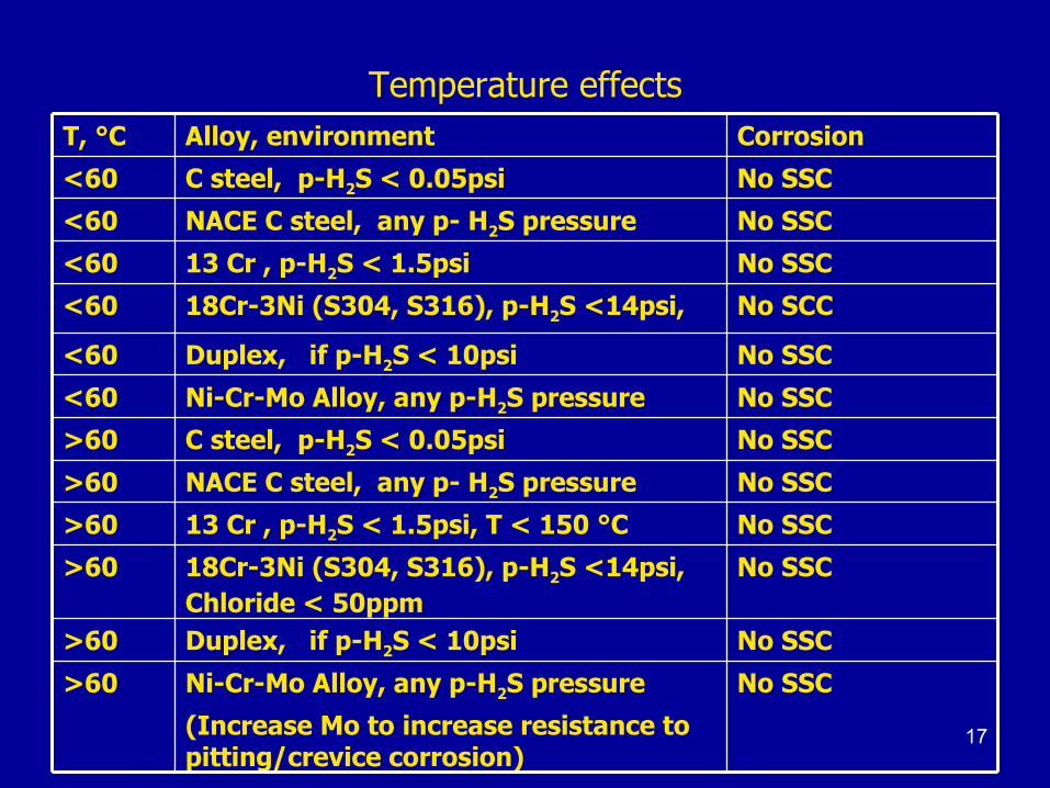
Temperature effectsT, °C Alloy, environment Corrosion
<60 C steel, p-H2S < 0.05psi No SSC
<60 NACE C steel, any p- H2S pressure No SSC
<60 13 Cr , p-H2S < 1.5psi No SSC
<60 18Cr-3Ni (S304, S316), p-H2S <14psi, No SCC
<60 Duplex, if p-H2S < 10psi No SSC
<60 Ni-Cr-Mo Alloy, any p-H2S pressure No SSC
>60 C steel, p-H2S < 0.05psi No SSC
>60 NACE C steel, any p- H2S pressure No SSC
>60 13 Cr , p-H2S < 1.5psi, T < 150 °C No SSC
>60 18Cr-3Ni (S304, S316), p-H2S <14psi, Chloride < 50ppm
No SSC
>60 Duplex, if p-H2S < 10psi No SSC
>60 Ni-Cr-Mo Alloy, any p-H2S pressure
(Increase Mo to increase resistance to pitting/crevice corrosion)
No SSC

18
CO2 dominant mechanism
Partial pressure - Carbon dioxide (p-CO2)
< 7 psi : noncorrosive Exception to above – If VFA >300ppm
7 to 15 psi : may be corrosive 15 to 30 psi : corrosive > 30 psi : very severe corrosive Stable FeCO3 - temperature : 60 - 120°C
Ca++/HCO3- < 0.05 – 0.1 : Corrosion risk low Ca++/HCO3- > 0.1 : Corrosion risk high If p-CO2/p-H2S >500, & p-H2S <0.01psi
18

19
CO2 + H2S environment
p-H2S is < 0.01 psi CO2 dominant mechanism p-H2S is ≥ 0.05 psi : NACE sour medium
MOC must comply NACE MR0175/ ISO15156 Ratio p- CO2 / p-H2S
< 20 : Severe sour Mechanism 20-500 : Transition >500 : CO2 mechanism p-H2S > 10psi likelihood - solid Sulphur (If drastic pressure loss at well bore) S deposition certain – if H2S >5% : in just 3-4 hours bottom hole may get choked up with SS problem significantly low in Oil wells
19

20
Beneficial effect of Mackinawite 0.05 to 1.25psi : p- H2S
10 to 50% of predicted for CO2 alone environment
Mackinawite :FexSy with Fe : 50.9 to 51.6%
If pH is >5 Excellent protective sulphide If pH : 4.0 to 5.0 transition effectsIf pH 3.5 – 4.0 localized deformation of
sulphide

21
CO2 + H2S
Poor Protective sulphide scale: high corrosion
If High CO2 + High H2S Protective Sulphide scale: low corrosionLow CO2 + High H2S Low CO2 + Low H2S
High H2S Pitting & Crevice at high H2S likely
21

22
Guideline on p-CO2 X pH
If p- CO2 > 87psi
pH < 3.5 If p-CO2 : 87 – 8.7psi
pH : 3.5 to 4.0 (depends on p-H2S)
If p-CO2 < 8.7psi
pH >4.0
22

23
Flow dynamics and Bubble point
Deviated well Corr. failure - lower half side tubingOil wells Log -water content of flowing emulsion :
Increase in water with depth Bubble point – near wellhead: release of acid gases
from oil phase into gas phase near wellhead Less likely availability of acid gas at well bottom Take calculated risk - carbon steel casing
23

24
Industry Practices: Reported in public domain
UK Offshore HSE document (Practiced in US, Canada also)
Greater than 6mm/year : CRA Less than 6mm/year : carbon steel (corrosion allowance, inhibition and process
control)NACE Paper on practices at British Petroleum
fields Cut off value : 8mm/year NORSOK M-001 standard Cut off value for inhibited cor. rate : 10mm/design life years 24

25
Specific precautions for sour wells
Sulphur deposition problems Normally oil wells – do not take place
In HPHT gas wells – likely deposition if T <110°C & H2S mole % > 5
If PVT study shows S deposition at well P & T If de-aeration of well completion fluids not done-
oxygen influx into formation
Oxygen with H2S forms S
Solid S – severe deposition in downhole S is very corrosive Must – periodic Sulphur solvent treatment
25

26
Carbon steel Acceptance
p-CO2 <3psi, p-H2S <0.05psi T: 60-120°C
Use Cor.Allowance(CA)
p-CO2 >3psi, p-H2S<0.05psi, T:60-120°C
Cor.rate < 6mm/y Use Inhibitor + CA,
p-CO2>3psi, p-H2S>0.05psi, T>60°C, Chloride<5000
Cor.rate <6 mm/y NACE C steel +Inhibitor + CA
p-H2S >0.05psi, p-CO2/p-H2S >500
Cor.rate < 6mm/y NACE Carbon Steel + Inhibition + CA
26

27
CRA selectionSweet service, T<100C 9 Cr-1Mo
Sweet service, T<150C 13 Cr
Sour, p-H2S<1.5psi, Cl<10000ppm T<150C 13Cr
Sour, p-H2S<3psi, Cl < 100000ppm Cold worked Duplex/Super duplex
Sour p-H2S<10psi, Cl <100000ppm Annealed Duplex
Sour, p-H2S : any value, No Sulphur Ni-Cr-Mo (Ni >22%)Alloy 28, Incoloy 825
Sour p-H2S <70psi, S, chloride : any, T < 204°C Incoloy 625
Sour p-H2S >70psi, S, chloride : any T < 232°C C-276
27

28
B-193 cluster wells study Superficial liquid velocity << 0.4m/s Water wetting of bottom hole tubular p-H2S > 1.25psi, No protective scaling by Mackinawite High electrochemical metal dissolution Cor.rate > 6mm/y & pH 3.3 - 3.5 Severity higher for gas wells than oil wells. High CO2 & High H2S NACE Carbon steel take care of Cracking failures NACE Carbon steel can not contain high metal dissolution Difficult to get corrosion inhibitor with >95% inhibition Carbon steel ruled out Solution : CRA MOC
28
29
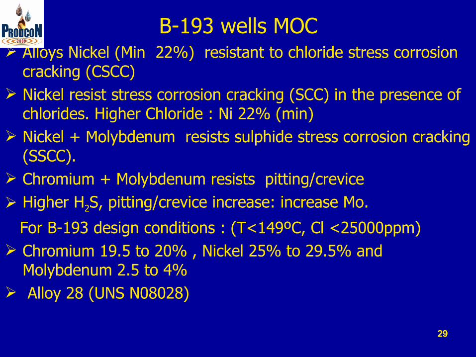
B-193 wells MOC Alloys Nickel (Min 22%) resistant to chloride stress corrosion
cracking (CSCC) Nickel resist stress corrosion cracking (SCC) in the presence of
chlorides. Higher Chloride : Ni 22% (min) Nickel + Molybdenum resists sulphide stress corrosion cracking
(SSCC). Chromium + Molybdenum resists pitting/crevice Higher H2S, pitting/crevice increase: increase Mo.
For B-193 design conditions : (T<149ºC, Cl <25000ppm) Chromium 19.5 to 20% , Nickel 25% to 29.5% and
Molybdenum 2.5 to 4% Alloy 28 (UNS N08028)
29

30
B-22 Wells MOC
High CO2 + Low H2S category
Partial pressure of H2S < 1.5 psi
T : 100°C pH - 3.6 to 3.9 P-CO2 > 32 - 130 psi
Corrosion rate : 1.55 -31.6mm/y High Chrome steel (>11% Cr ) resistant 13 Chromium steel : API 5CT L80 Type 13 Cr
30

31
Tubular MOC for B-193 & B-22
C steel not adequate ( with CA & inhibition)Conclusion : CRA – Alloy 28 or 13 Cr steel Solid wall tubular CRA - high CAPEX
Relative Cost comparison C steel : 1.00NACE C steel : 1.0413 Cr steel : 4.00Alloy 28 : 10.00
31

32
Reports of Cost effective -CRA Well completions
2001: Cheveron Canada – Fort Liard gas wells ( Tail pipe, tubing below packer : High Nickel alloy
2004: ExxonMobil – Big Escambia Creek field, USA:Sour gas – Incoloy 825 as tail tubing below mandrel for cor.inhibitor
2004: Shell Global & Abu Dhabi National Oil Co. (ADNOC) - Bottom CRA (below CRA packer) for 33%H2S gas wells
2004: IEOT Recommended - CRA liner for bottom 200m of ISC injector wells – Santhal & Balol fields, Mehsana
2002: Acid gas disposal wells at Canada – CRA for injection zone
32

33
Proposal for Well completion
Hybrid type : CRA – Carbon steel combination And
Adoption of Technology for
Tubing integrity Internal tubing- CRA clad Technology developed in US
Galvanic Corrosion Prevention Couple as per USA patent 5906400 Coating as per guideline of NORSOK M-001 33
34
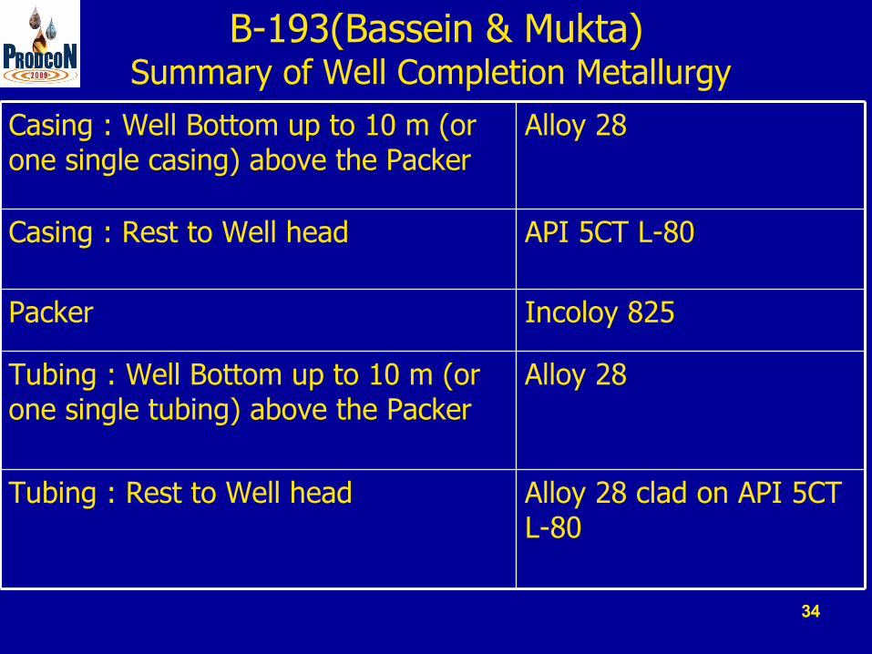
B-193(Bassein & Mukta)Summary of Well Completion Metallurgy
Casing : Well Bottom up to 10 m (or one single casing) above the Packer
Alloy 28
Casing : Rest to Well head API 5CT L-80
Packer Incoloy 825
Tubing : Well Bottom up to 10 m (or one single tubing) above the Packer
Alloy 28
Tubing : Rest to Well head Alloy 28 clad on API 5CT L-80
34

35
Well Completion : B-193 Wells
35

36
B-193 (Panna Formation) & B-22 Summary of Well Completion Metallurgy
Casing : Well Bottom up to 10 m (or one single casing) above the Packer
API 5 CT L-80 Type 13 Cr Steel
Casing : Rest to Well head API 5CT L-80
Packer 13 Cr Steel
Tubing API 5 CT L-80 Type 13 Cr Steel
36

37
Well Completion : B-22 Wells
37

38
Bimetallic Galvanic Corrosion
38
39
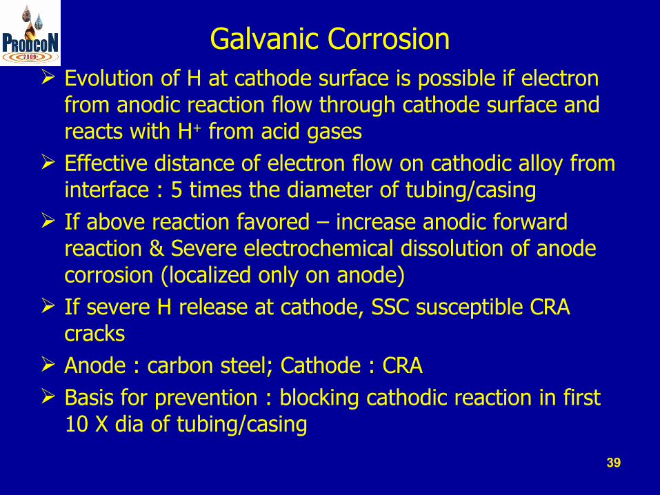
Galvanic Corrosion Evolution of H at cathode surface is possible if electron
from anodic reaction flow through cathode surface and reacts with H+ from acid gases
Effective distance of electron flow on cathodic alloy from interface : 5 times the diameter of tubing/casing
If above reaction favored – increase anodic forward reaction & Severe electrochemical dissolution of anode corrosion (localized only on anode)
If severe H release at cathode, SSC susceptible CRA cracks
Anode : carbon steel; Cathode : CRA Basis for prevention : blocking cathodic reaction in first
10 X dia of tubing/casing
39

40
Galvanic corrosion prevention Couple features
1. Design as per USA Patent, 5906400, 5.5.1999 2. Coating as per NORSOK M-001 standard, August, 2004 Guideline: High temperature resistant coating length The length “d” : 10 times the diameter of the casing
pipe : for 7 inch casing, d = 6 feet
40

41
High Temperature Oxidation Environment
Injector wells of In-situ combustion(ISC) for EOR, at Santhal and Balol heavy oil fields of Mehsana Asset
Injector wells of Air Injection Pilot for EOR at Gamij light oil field, Ahmedabad Asset.
41

42
In-Situ-Combustion EOR process
42

43
Well Bottom : High temperature Oxidation
Combustion front temperature: Initial temperature 450 – 550 ˚C for ISC injector wells : Heavy oil 350 ˚C Injector wells : light oil Stable temperature : 70 ˚C (During air/water injection)Air injection under high pressureAlternate Water Injection under high pressure
43

44
MOC for In –Situ-Combustion Injector Wells
9 % Cr steel resistant to High temperature oxidation, alternate moist air and injection water
Upset : influx of flue gases –CO2 & heat from the burning front
Conservative Approach : 13 Chromium steel (UNS S42000)
Well Completion similar to B-22 well.
44

45
Well Completion : ISC injector wells
Final casing 7 inch
Tubing, 13 CrTubing, 13 Cr
3 ½ inch ф Tubing, 13 Cr steel
Final casing, 7 inch ф

46
In-Situ-Combustion Injector Wells Summary of Well Completion Metallurgy
Casing : Well Bottom up to 10 m (or one single casing) above the Packer
API 5 CT L-80 Type 13 Cr Steel
Casing : Rest to Well head API 5CT L-80 Type 1
Packer 13 Cr Steel
Tubing API 5 CT L-80 Type 13 Cr Steel
46

47
Summary and Recommendations
Novel hybrid well completion metallurgy –technically feasible for : Sour oil & gas wells and ISC injector wells.
Casing: Casing - CRA component in the bottom hole up to one
single above CRA packer (Incoloy 825) Casing- Rest to well head - carbon steel. 1. with galvanic corrosion prevention couple 2. With NORSOK M001 Aug 2004 guideline for Coating
Tubing: 1. With Tubing integrity by Internal CRA clad for Sour wells. 2. Solid CRA tubing for ISC injector wells.
CRA for high H2S wells of B-193 : Alloy28 CRA for High CO2 wells of B-22 : 13 Cr CRA for ISC Injector wells : 13 Cr

48
Thanks