rules, precursors and parameterization methodologies for ...eprints.whiterose.ac.uk/89017/1/rules,...
TRANSCRIPT

This is a repository copy of Rules, precursors and parameterization methodologies for topology optimized structural designs realized through additive manufacturing.
White Rose Research Online URL for this paper:http://eprints.whiterose.ac.uk/89017/
Version: Accepted Version
Proceedings Paper:Muir, MJ, Querin, OM and Toropov, V (2014) Rules, precursors and parameterization methodologies for topology optimized structural designs realized through additive manufacturing. In: 10th AIAA Multidisciplinary Design Optimization Specialist Conference (AIAA SciTech). 10th AIAA Multidisciplinary Design Optimization Specialist Conference, 13-17 Jan 2014, National Harbor, Maryland, USA. American Institute of Aeronautics and Astronautics . ISBN 978-1-62410-310-0
https://doi.org/10.2514/6.2014-0635
© American Institute of Aeronautics and Astronautics 2014. This is an author produced version of a paper published in 10¬th AIAA Multidisciplinary Design Optimization SpecialistConference (AIAA SciTech). Uploaded in accordance with the publisher's self-archiving policy.
[email protected]://eprints.whiterose.ac.uk/
Reuse Unless indicated otherwise, fulltext items are protected by copyright with all rights reserved. The copyright exception in section 29 of the Copyright, Designs and Patents Act 1988 allows the making of a single copy solely for the purpose of non-commercial research or private study within the limits of fair dealing. The publisher or other rights-holder may allow further reproduction and re-use of this version - refer to the White Rose Research Online record for this item. Where records identify the publisher as the copyright holder, users can verify any specific terms of use on the publisher’s website.
Takedown If you consider content in White Rose Research Online to be in breach of UK law, please notify us by emailing [email protected] including the URL of the record and the reason for the withdrawal request.
American Institute of Aeronautics and Astronautics
1
Rules, Precursors and Parameterization Methodologies for
Topology Optimized Structural Designs Realized Through
Additive Manufacturing
Martin J. Muir1
EADS Innovation Works UK, Filton, Bristol, England, BS997AR
Vassili V. Toropov.2And Osvaldo M. Querin
3
University of Leeds, Yorkshire, England, LS29JT
Additive manufacturing, more commonly known as 3D printing is a rapidly developing,
thoroughly novel means of producing complex, previously difficult to manufacture
components. Slowly divorcing itself from previously held preconceptions of rapid
prototyping and now capable of producing comparable structures from materials such as
titanium and high strength nickel alloys, it is a means of manufacturing structures deemed
too complex for existing fabrication techniques. Whilst free of conventional constraints, the
unique intricacies of the manufacturing process can lead to the creation of factors,
detrimental to production success. The research detailed within this paper demonstrates
through example, how the orientation of a part prior to build can be optimized in order to
significantly mitigate these effects and to maximize build economics. Furthermore the
research details a new method for the combined assessment and tailored structural topology
optimization of parts intended for production by specific additive manufacturing
technologies.
Nomenclature
AM = Additive Manufacturing
BE = Build Economics
DMLS = Direct Metal Laser Sintering
DR = Design Rules
EBM = Electron Beam Melting
GD = Geometric Distortion
RS = Residual Stress
SLM = Selective Laser Melting
SR = Surface Roughness
STO = Structural Topology Optimization
I. Introduction
dditive manufacturing (AM) [1] is perhaps the most import developing technology for industrial consumers of
high value, lightweight components such as commercial aerospace [2]. Capable of producing highly complex
geometric profiles with almost unparalleled efficiency and accuracy, the processes which together make up AM,
1Research Engineer, TCC2 Metallic Technologies, Building 20A1, Airbus Operations, Filton, Bristol, England,
BS99 7AR, Member AIAA. E-mail [email protected] of Aerospace and Structural Engineering, Faculty of Engineering, University of Leeds, West Yorkshire,
England, LS2 9JT. AIAA Associate Fellow. E-mail [email protected] Professor, Faculty of Engineering, University of Leeds, West Yorkshire, England, LS2 9JT. AIAA
Senior Member. E-mail [email protected].
A

American Institute of Aeronautics and Astronautics
2
promise to revolutionize the manufacturing industry. The ability of powder bed (PB) AM to realize designs with
almost no conventional manufacturing constraints, has led, almost inevitably, to the combining of AM with almost
freeform Structural Topology Optimization (STO) as a means to capitalize on the benefits of both technologies.
Whilst it is broadly correct to state that the use of AM can eliminate a swathe of conventional manufacturing
constraints from the design process; the use of these novel industrial technologies introduces additional complexities
which must first identified, and then accounted for in any applied design process. Design rules (DR) for AM are a
highly complex and contentious issue, requiring intimate knowledge of myriad aspects relating to the design and
manufacture process, for multiple, often disparate AM technologies [3] The work performed as part of this
investigation addresses numerous technical considerations including, but not limited to: end user design
requirements/rules; the operational physics of the AM processes; the metallurgical properties ascribed to AM
techniques; and the effect of geometric profiles and build orientation on as built metallurgical properties. Primarily,
a series of non-topologically Optimized component geometries are evaluated in response to the identified technical
considerations; a formulated multi-objective optimization problem is then used to minimize the adverse AM effects
through orientation modification, customized support structure and variation of process parameters. A secondary
analysis with a view towards the use of STO is then undertaken; using the outputs (build orientation and proposed
supporting structure) of the primary analysis as design inputs, alongside initial customer design requirements and
constraints, a strategy for detailed Parameterization of the STO input is created. The outputs of the STO are then re-
analyzed and compared to the design inputs from the stage one analysis in order to determine their effectiveness.
Together, the work demonstrates a substantial step forward in amalgamation of STO and AM by tailoring the
application of both approaches to their inherent strengths, through understanding of their greatest limitations.
A. Scope and Limitations
In order to manage the scope of the investigation, this research focused only on those AM techniques which
demonstrate the highest levels of technical maturity, therefore having the most relevance to the aerospace sector.
Whilst there are currently hundreds of different AM platform providers, with many more non-commercial machines
established at universities and research laboratories, the vast majority can be broadly categorized into three distinct
classes; PB, Directed Energy Deposition and Wire-fed [4].
Currently only PB AM techniques demonstrate suitable levels of process maturity, and as such, only these
techniques will be included in the scope of the topic. Furthermore, whilst several platform vendors exist for metallic
AM, the vast majority are broadly similar [5] and have analogous technical limitations. Therefore, the two dominant
techniques in the field are the intended research focus. EOS Direct Metal Laser Sintering (DMLS) [6] is the most
commonly used platform for laser based PB AM, Conversely, Electron Beam Melting (EBM) [7] is the dominant
form of electron beam based PBAM technology. Together, and as of this date, these two technologies represent the
largest adoptions of AM platforms in the aerospace industry, thereby justifying their inclusion within the project
scope.
B. Technical Limitations of Shortlisted AM Processes
Within the bounds of the technical considerations for the investigation, a number of factors are present which
can, if unaddressed, seriously inhibit the ability of AM to successfully produce parts which are deemed fit for
purpose; Material Properties are one such area. Though generally considered as good, with properties similar to, or
in some cases exceeding, metallic properties for castings, AM material properties do suffer significantly in one key
area…fatigue performance. There are several known [8] and even more theorized [9] reasons for this exhibited
deficiency in additive manufactured parts, with a large percentage ascribing blame to surface finish. However, there
is also data which suggests that porosity [10] and material microstructure [11] can elicit similar knockdown factors.
In addition, there is emergent research [12] which suggests that certain geometric features in AM slices can have
significant effects on microstructure and therefore fatigue performance. Identification and parametric inclusion of
those geometric features with design rules for AM is a key area for a combined approach to design Optimization.
If one considers a software-only-approach on a platform which is locked for production, one in which laser
properties, powder metallurgy and process changes cannot be altered, one must adapt the design of a part, in order
that it best suits the known deficiencies of the process in order to achieve the best results. Of the known factors
affecting PB AM produced parts, perhaps the most debilitating are related to surface roughness (SR), geometric
distortion (GD) and build economics (BE). The most obvious of these flaws to any outside observer would be the

American Institute of Aeronautics and Astronautics
3
substantial roughness found on the surface of most (though this varies between materials and processes) additively
manufactured metallic parts. It is common attribute of AM and is formed as an artifice of using a layer-wise method
of construction through a highly focused energy source. SR is arguably caused and exacerbated by a number of
factors [13]; principally, the major contributors to increased SR are related to energy overspill [14] layer thickness,
powder particle size [15], energy properties [16] and highly overhung angled surfaces [17]. Most of the factors
listed above fall outside the scope of this investigation as they are part of the platform parameters. However, SR
problems encountered due to overhanging surfaces can be reduced through careful build orientation.
C. Surface Roughness and Overhanging SurfacesAngled or overhanging surfaces (surfaces which are varyingly angled with respect to the XY plane) represent a
multifold problem for all AM production techniques due to the manner in which AM production works; principally,
each layer of an AM build represents a geometrically complex, microscopically thin plate; at the edges of these
plates a contour profile is drawn which is largely perpendicular to the plate surface. As such, any overhanging
surface will (when examined closely) resemble a step function. Figure 1 shows the appearance of this step function
and its effect on surface roughness with decreasing angles of the build. Furthermore, also demonstrates the
significant compounding effect of larger layer sizes and angle surfaces upon SR.
Figure 1. – Effect of surface overhang and layer thickness upon surface roughness
Though somewhat dependent upon layer-thickness/build-angle and process type, it is common in PBAM techniques
to support (during build) overhanging/angled faces in order to prevent geometric distortion. These required support
structures can cause significant increases in SR as shown in Figure 2 The combination of an increase in required
supporting structures for AM builds [18] The use of support structure and levels of variation in relation to their
application are well documented [19] however research into their effects on SR and methods to reduce it are less
well researched.
Figure 2. - Effect of support structure type on part surface roughness

American Institute of Aeronautics and Astronautics
4
D. Geometric Distortion in Powder Bed Additive Manufacturing
Initially, both PB AM processes (DMLS and EBM) appear broadly similar in their approach to AM, however,
the similarities are only superficial. Whilst both platforms use a CAD input along with a feedstock comprised of
layered, atomized metallic powder, the manner in which the required input energy is applied, differs vastly between
the two. DMLS is a cold process (~25) conducted within an Argon filled chamber, with all input energy accurately
applied directly to the part slices via either a 200w or 400w CO2 based laser. Conversely, EBM is a hot process
(~700) and is conducted within a vacuum, this time with preheating performed in-between each applied layer using
a defocussed EB, prior to refocusing the beam energy for the primary melt. The temperature difference between the
processes creates significant differences in material microstructure [14] but more importantly, is a contributing
factor in the formation of significant residual stress (RS) factors within the colder DMLS process. The effects of this
stress formation within DMLS processes can vary significantly and are highly geometry specific [20] In mild cases,
the appearance of witness lines can be attributed to RS effects [21] and in more extreme cases they can cause a
complete build crash. Minimization of RS factors and effects in DMLS processes are a key area of research for the
industrialization of the DMLS processes. Minimization of these stresses and their subsequent distortions is of
particular importance for the DMLS process.
In both SR and RS, the use of, along with the minimization/mitigation of the effects of supporting structures during
the build are critical, and are often not convergent for any particular strategy. More simply, in order to counteract the
effects of distortion (due to RS) and increase the likelihood of a successful build (thereby minimizing cost),
additional support structure is used to anchor the part to the build-plate. Conversely, the addition of support structure
not only increases surface area for processing, but also part roughness and the requirement for post processing of the
part afterwards, all of which thereby increase part cost, waste and time. A method of minimizing the required
supports due to either projected surface overhang or predicted residual stress is required.
E. Build Economics
Build economics are affected by myriad different factors, and quite process specific. However, there are a number
of commonalities to both processes which can, and should be included into any Optimization strategy. The first and
most obvious is that related to build completion, any strategy which increases the risk of a build failure should be
discouraged as machine time and powder are particularly expensive. Factors which can incur the risk of build
failure relate to both geometric distortion and total scan area and are somewhat interrelated. A second factor relates
to build time, usually exemplified by maximum (Z) height of the part. These factors can be controlled the constraint
and penalization functions during the Optimization.
II. Problem Formulation
In order to fully define the optimization requirements, categorization of identified detrimental factors and
potential design variables in selected AM processes was first required. Following this, factors which could influence
the technical limitations of AM techniques and be varied in a discrete manner were sought. Several potential
candidates known to have effects in multiple domains were identified, these included beam properties, hatching
strategy and orientation. However, it was determined that whilst all identified criteria all had (arguably) large
effects, most fell outside the scope of this investigation due the dependence upon machine hardware/software
parameters rather than design for manufacture assessment and Optimization. Ultimately, it was deemed important to
mitigate the AM limitations in the primary design and nesting phases, with nesting an orientation being
accomplished in the primary phase of Optimization.
Due to its inherent interrelation with all three AM limitations, the principal variable in the primary Optimization
study is thusly related to preliminary build orientation; As a start point, and for each investigated structure, an
empirically determined build orientation is initially defined and subsequently analyzed for its effectiveness in terms
of SR, RS and BE. For each structure analyzed, the range of variation from its defined origin in the primary study
relates to its rotation about either the X and/or Y axes in the range +/- 15° from the Z axis. This gives a total range
of 30 degrees in either axis of rotation, and a total number of possible designs close to 1000 possibilities.
American Institute of Aeronautics and Astronautics
5
F. Metamodelling for Simulation Reduction
Due to the complexity of the slicing program the time required for a comprehensive investigation and
comparison of each design point is both computationally expensive and infeasible should the process be used for
subsequent structural analyses. A more computationally efficient and expedient method was required.
Metamodeling techniques are designed to provide just such a solution and have receiving wide employment in
engineering design in order to improve the efficiency of optimization in design systems which are based on
computationally expensive simulation. Based on the number of projected DOE points and the likely variability in
the derived functions due to the vast complexities of changeable input geometry, a moderately large sample size of
120 points was determined to be adequate enough to allow suitable complexity whilst substantially reducing
complexity. A customized Latin Hypercube design was selected as the optimal method for domain sampling based
on established data (REF) makes an , a series of sample points are used to create a metamodel upon which the
preliminary Optimization study is performed. Whilst both low SR and low RS are requirements of the Optimization,
they are, at this juncture reformulated into constraint functions with maximal values applied to each function. In this
way, the minimization of surface overhangs can be formulated as the primary objective function for the problem.
With design variables and sampling methodology established, formulation of the remaining factors for the
Optimization could proceed. Problematically and as previously established, there are three (potentially competing)
different objectives for the any Optimization study in which one attempts to address the problems concerning the use
of design to address AM related build issues; maximize build economics (Max BE), minimize residual stress (Min
RS) and maximize quality whilst minimizing required support structure (Min SR). In essence there are 3 objective
functions.
There exists a number of methods by which one can Optimize for multiple objective functions; firstly one can
include multiple objective functions within the optimization problem, applying weighting functions/multipliers in
order to bias/stabilize the optimization output [22] Problematically, this further increases the computational load
which has been previously reduced and is an unattractive position in an already computationally demanding
simulation. Alternatively, objectives can be reformulated into constraint functions based on minimum requirements
and applied separately to the operational domain. This approach was selected for use in the investigation. In this
instance the primary objective function is the minimization of SR. Constraints are then placed on build time and
ascribed cost, based on the outputs of a devised costing model for both processes. Finally, residual stress is applied
as a further constraint function using outputs of the slice analysis to identify and penalize factors known to cause
increases in stress formation during layer on construction.
G. Optimization Summary
To summarize, the primary Optimization variable is related to orientation variation allowing rotation of +/-15
deg about both the x and y axes. These variables are obtained using sampling techniques to create a metamodel
upon which the Optimization is solved. Constraints are placed on the maximum percentage of overhanging surfaces
with significant penalization applied to those surfaces at angles less than 65 deg from the build plate which would
subsequently require support. Build economics are constrained within 10% of the original maximum Z height of the
primary design, with XY surface coverage similarly constrained. Stress formation is constrained using slice-file
analysis to predict and penalize likely stress raisers in the design. The objective of the Optimization is the
minimization of surface roughness for as-built parts based on surface overhang.
III. Geometry Cases
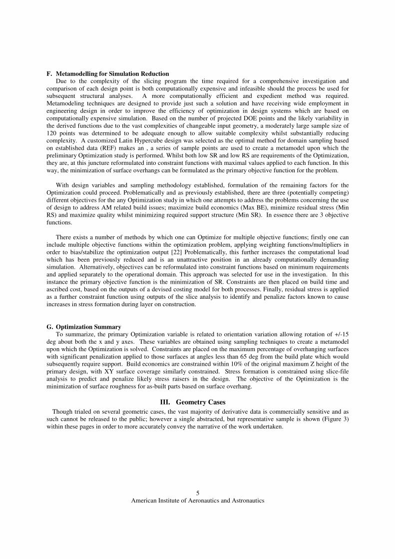
Though trialed on several geometric cases, the vast majority of derivative data is commercially sensitive and as
such cannot be released to the public; however a single abstracted, but representative sample is shown (Figure 3)
within these pages in order to more accurately convey the narrative of the work undertaken.
American Institute of Aeronautics and Astronautics
6
Figure 3. - Geometric case study for Optimization analysis
IV. Preliminary Analysis
Using existing processes and techniques, each component was analyzed by an experienced technician and placed
in the perceived best orientation for minimization of residual stress and maximization of quality at the expense of
economics. A custom made STL slicer was then used to bisect the components parallel to the platform build plate at
an interval of 100microns. Each layer is then analyzed and its mass properties and surface angles in relation to the
build platform are calculated. Allowing up to a +/-15 degree rotation about both the X and Y axes, the various
combinations of rotations define the design variables for the primary optimization. Using a gradient based
Optimizer, minimization of angular structures below 65 and in excess of 130 degrees, the amount of required
support structure is reduced and the maximization of reduced SR is attained.
V. Preliminary Analysis Results and Comparison
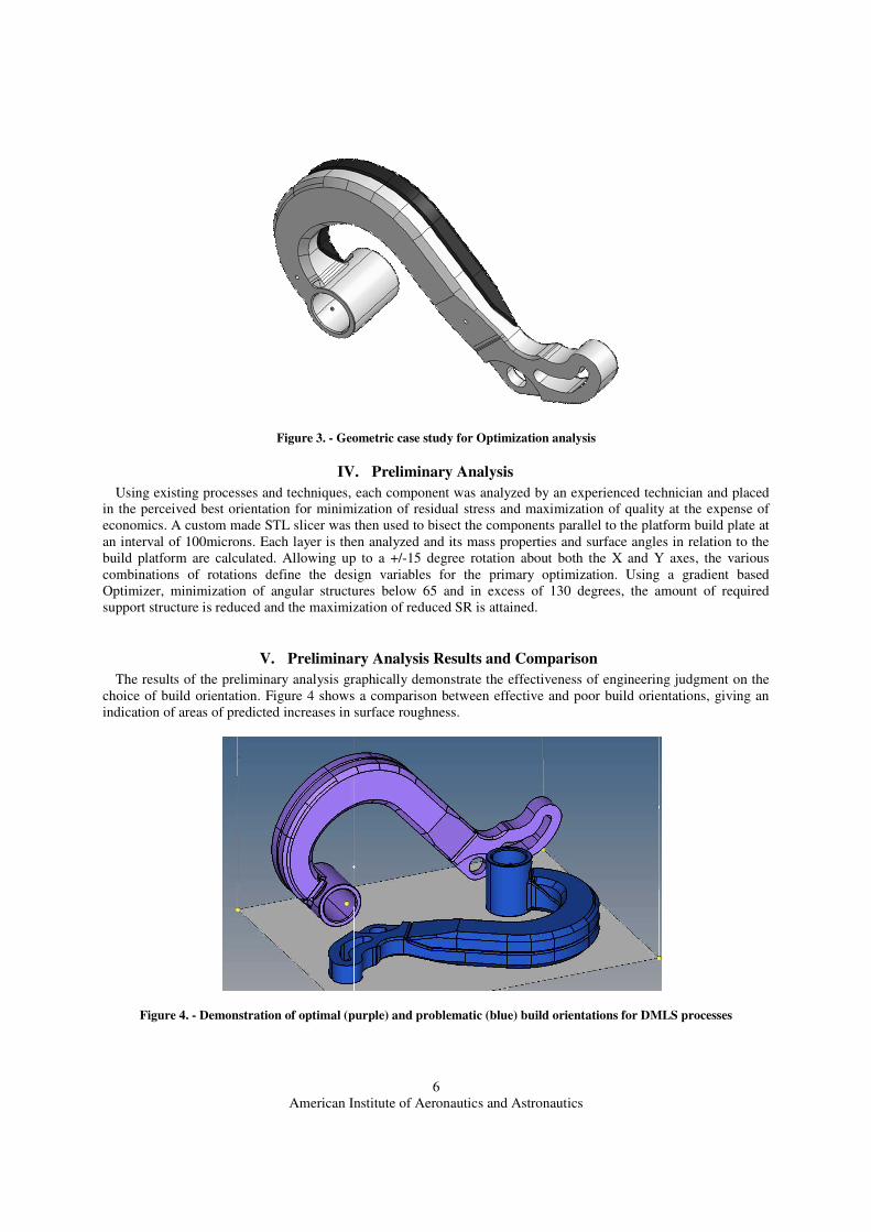
The results of the preliminary analysis graphically demonstrate the effectiveness of engineering judgment on the
choice of build orientation. Figure 4 shows a comparison between effective and poor build orientations, giving an
indication of areas of predicted increases in surface roughness.
Figure 4. - Demonstration of optimal (purple) and problematic (blue) build orientations for DMLS processes

American Institute of Aeronautics and Astronautics
7
Figure 5. – Chart showing the number of overhanging surfaces for un-Optimized orientation setup
Figure 6. – Chart depicting the changes in area for layer-wise construction of components

American Institute of Aeronautics and Astronautics
8
VI. Primary Optimization Results
The results of the primary Optimization phase graphically demonstrate Figure 7 the effectiveness of design
assessment prior to a final build setup and manufacture. Through small variations in build orientation which were
unobserved by an experienced operator significant reductions in both SR and RS are seen in the resulting slice file
analysis.
Figure 7. – A direct comparison of preliminary part setup and the newly derived optimal build orientation
Figure 8. - Comparison of overhanging surfaces on optimum build setup vs. preliminary assessment setup
An analysis of the raw data which makes up Figure 8 demonstrates a potential reduction in surface overhang of
almost 11% and a subsequent reduction in required support of some 17% leading to a further reduction in SR.
American Institute of Aeronautics and Astronautics
9
It can also be seen in Figure 9 that the predicted mass changes during construction have substantially smaller and
less positive gradients, which research suggest should allow for substantive reductions in residual stress when
produce using the DMLS or other Selective Laser Melting (SLM) based Am platforms.
Figure 9. - A comparison of layer-wise mass changes between preliminary and optimal build orientation
The results inevitably show that even when setup by an experienced operator, a substantial refinement in build
orientation can be provided through careful use of simulation, modelling and Optimization. Furthermore, the
effectiveness of the Optimizer on component geometry and orientation setup are significantly more pronounced on
structures with complex geometry which requires careful support strategies in order to build effectively. This would
be especially true in the case of a topology Optimized structure possessing of the complex truss type features which
typify topology Optimized structural designs.
VII. Continuing Work – Secondary Optimization
The penultimate stage of this research focuses upon methods intended to integrate the use of the preliminary
Optimization stage into the initial Parameterization for combined topology Optimized structural design. Through
use of a multi-stage Optimization in which the primary Optimization phase demonstrated within this paper is used in
conjunction with a conventional freeform structural topology Optimization in order to provide the inputs for the
combined approach.
This secondary analysis is intended to tailor the use of STO for the selected additive manufacturing processes
through use of the outputs from the primary analysis (optimum build orientation and bespoke support strategy) as
design Parameterization inputs for structural topology optimization. Using conventional methods, a compliance
based optimization problem is then formed around the original topology for each of the analyzed components.
Additional parameterization is applied in two phases, the first uses specifically developed automated techniques [23]
in order to define constraint attachments [24] non-design space and optimization parameters in an expedient manner.
The second phase uses the determined optimal build orientation along with parameters for self-supporting structures
bespoke for each am process.
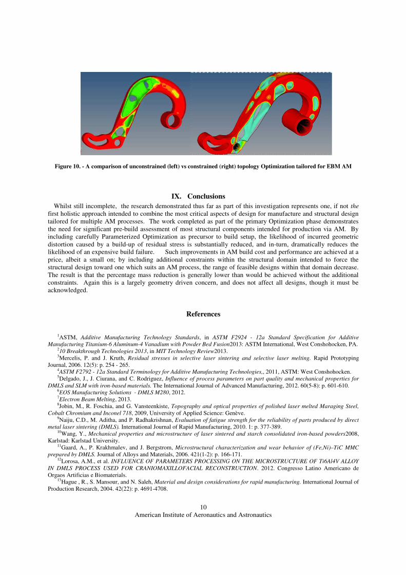
VIII. Secondary Optimization Results
A three tranche comparison of the compliance optimization was performed during this stage, the first tranche
approach is a relatively freeform optimization featuring conventional/manually applied constraints and optimization
techniques, the second tranche uses the advanced automated Parameterization techniques [25] in order to more
heavily constrain the Optimized de technique was devised in order to aid design extraction through heavy use of
Parameterization and at the expense of computational efficiency. The final tranche builds upon the techniques of its
predecessors to further tailor the STO output to AM production techniques. Using Boolean functions and sliced
mass properties connected via B-splines, the Optimized structural output from tranche 2 is used to introduce heavily
penalized domain sectors, designed to constrain the optimization process into structural pathways which are
conducive to unsupported AM production. Figure 10 demonstrates the dramatic difference in the outputs of
structural optimization when additional constraints for the AM production technique are applied to the initial
parameterization.
American Institute of Aeronautics and Astronautics
10
Figure 10. - A comparison of unconstrained (left) vs constrained (right) topology Optimization tailored for EBM AM
IX. Conclusions
Whilst still incomplete, the research demonstrated thus far as part of this investigation represents one, if not the
first holistic approach intended to combine the most critical aspects of design for manufacture and structural design
tailored for multiple AM processes. The work completed as part of the primary Optimization phase demonstrates
the need for significant pre-build assessment of most structural components intended for production via AM. By
including carefully Parameterized Optimization as precursor to build setup, the likelihood of incurred geometric
distortion caused by a build-up of residual stress is substantially reduced, and in-turn, dramatically reduces the
likelihood of an expensive build failure. Such improvements in AM build cost and performance are achieved at a
price, albeit a small on; by including additional constraints within the structural domain intended to force the
structural design toward one which suits an AM process, the range of feasible designs within that domain decrease.
The result is that the percentage mass reduction is generally lower than would be achieved without the additional
constraints. Again this is a largely geometry driven concern, and does not affect all designs, though it must be
acknowledged.
References
1ASTM, Additive Manufacturing Technology Standards, in ASTM F2924 - 12a Standard Specification for Additive
Manufacturing Titanium-6 Aluminum-4 Vanadium with Powder Bed Fusion2013: ASTM International, West Conshohocken, PA.210 Breakthrough Technologies 2013, in MIT Technology Review2013.3Mercelis, P. and J. Kruth, Residual stresses in selective laser sintering and selective laser melting. Rapid Prototyping
Journal, 2006. 12(5): p. 254 - 265.4ASTM F2792 - 12a Standard Terminology for Additive Manufacturing Technologies,, 2011, ASTM: West Conshohocken.5Delgado, J., J. Ciurana, and C. Rodriguez, Influence of process parameters on part quality and mechanical properties for
DMLS and SLM with iron-based materials. The International Journal of Advanced Manufacturing, 2012. 60(5-8): p. 601-610.6EOS Manufacturing Solutions - DMLS M280, 2012.7Electron Beam Melting, 2013.8Jobin, M., R. Foschia, and G. Vansteenkiste, Topography and optical properties of polished laser melted Maraging Steel,
Cobalt Chromium and Inconel 718, 2009, University of Applied Science: Genève.9Naiju, C.D., M. Aditha, and P. Radhakrishnan, Evaluation of fatigue strength for the reliability of parts produced by direct
metal laser sintering (DMLS). International Journal of Rapid Manufacturing, 2010. 1: p. 377-389.10Wang, Y., Mechanical properties and microstructure of laser sintered and starch consolidated iron-based powders2008,
Karlstad: Karlstad University.11Gaard, A., P. Krakhmalev, and J. Bergstrom, Microstructural characterization and wear behavior of (Fe,Ni)–TiC MMC
prepared by DMLS. Journal of Alloys and Materials, 2006. 421(1-2): p. 166-171.12Lorosa, A.M., et al. INFLUENCE OF PARAMETERS PROCESSING ON THE MICROSTRUCTURE OF Ti6Al4V ALLOY
IN DMLS PROCESS USED FOR CRANIOMAXILLOFACIAL RECONSTRUCTION. 2012. Congresso Latino Americano de
Orgaos Artificias e Biomaterials.13Hague , R., S. Mansour, and N. Saleh, Material and design considerations for rapid manufacturing. International Journal of
Production Research, 2004. 42(22): p. 4691-4708.

American Institute of Aeronautics and Astronautics
11
14Antonysamy, A.A.,Microstructure, Texture and Mechanical Property Evolution during Additive Manufacturing of Ti6Al4V
Alloy for Aerospace Applications2012, Manchester: School of Materials.15Ponader, S., et al., Effects of topographical surface modifications of electron beam melted Ti-6Al-4V titanium on human
fetal osteoblasts. Journal of Biomedical Materials Research Part A, 2008. 84A(4): p. 1111-1119.16Haslauer, C.M., et al., In vitro biocompatibility of titanium alloy discs made using direct metal fabrication. Medical
Engineering & Physics, 2010. 32(6): p. 645-652.17Lind, J.-E., et al. Rapid Manufacturing with Direct Metal Laser Sintering. 2002. MRS Proceedings.18Baufeld, B., O.V.d. Biest, and R. Gault, Additive manufacturing of Ti–6Al–4V components by shaped metal deposition:
Microstructure and mechanical properties.Materials & Design, 2010. 31, Supplement 1(0): p. S106-S111.19Kruth, J.-P., et al. BENCHMARKING OF DIFFERENT SLS/SLM PROCESSES AS RAPID MANUFACTURING
TECHNIQUES. 2005. Gent, Belgium: Polymers & Moulds Innovations.20Pohl, H., et al. Thermal Stresses in Direct Metal Laser Sintering. 2001. Solid Freeform Fabrication Symp.21Kruth, J., et al., Rapid Manufacturing of Dental Prostheses by means of Selective Laser Sintering/Melting. Bio-Materials
and Prototyping Applications in Medicine, 2009: p. 109-124.22Bendsoe, M.P. and O. Sigmund, Topology optimization: theory, methods and applications2003: Springer.23Muir, M. Civil Aerospace Mass Reduction Through Automated Topology Optimization and Advanced Manufacturing. . in
9th ASMO UK/ISSMO Conference on Engineering Design Optimization. 2012. Cork, Ireland.24Muir, M. Topology Optimization and Advanced Manufacturing for Civil Aerospace Applications. in Automated Design
Optimisation Seminar. 2012. Derby, England: Rolls Royce.25Muir, M. Multidisciplinary Optimisation of Business Jet MED Hinge for Production by Additive Manufacturing in 2013
European Altair Technology Conference. 2013. Lingotto, Turin, Italy: Altair Engineering.