rule change notice 1 - · pdf filerule change notice 1 common structural rules for double hull...
TRANSCRIPT
Common Structural Rules for Double Hull Oil Tankers, July 2010
Rule Change Notice 1 (1 July 2010 consolidated edition)
Notes:
(1) These Rule Changes enter into force on 1st July 2012.
(2) The Rule amendments in this document are applicable to the Common Structural Rules for Double Hull Oil Tankers, July 2010.
Copyright in these Common Structural Rules for Double Hull Oil Tankers is owned by:
American Bureau of Shipping Bureau Veritas China Classification Society Det Norske Veritas Germanischer Lloyd Korean Register of Shipping Lloyd's Register Nippon Kaiji Kyokai Registro Italiano Navale Russian Maritime Register of Shipping
Copyright © 2006 The IACS members, their affiliates and subsidiaries and their respective officers, employees or agents are, individually and collectively, referred to in this clause as the ‘IACS Members’. The IACS Members, individually and collectively, assume no responsibility and shall not be liable to any person for any loss, damage or expense caused by reliance on the information or advice in this document or howsoever provided, unless that person has signed a contract with the relevant IACS Member entity for the provision of this information or advice and in that case any responsibility or liability is exclusively on the terms and conditions set out in that contract.

RULE CHANGE NOTICE 1 COMMON STRUCTURAL RULES FOR DOUBLE HULL OIL TANKERS, JULY 2010
PAGE 2 OF 48
COMMON STRUCTURAL RULES FOR DOUBLE HULL OIL TANKERS, JULY 2010
RULE CHANGE NOTICE 1 This notice contains amendments within the following Sections of the Common Structural Rules for Double Hull Oil Tankers, July 2010. The amendments are effective on the dates shown:
Section Paragraph/Figure/Table Effective Date
Section 4 2.6.3.6 1 July 2012
Section 4 3.2.5.1 1 July 2012
Section 4 3.4.1.4 1 July 2012
Section 6 1.2.3.1 1 July 2012
Section 6 Table 6.1.3 1 July 2012
Section 6 2.1.1.2 1 July 2012
Section 6 Figure 6.3.1 1 July 2012
Section 6 4.1.2.3 1 July 2012
Section 7 Table 7.6.1 1 July 2012
Section 8 1.1.2.2 1 July 2012
Section 8 1.2.2.2 1 July 2012
Section 8 1.3.2.2 1 July 2012
Section 8 1.3.4.1 1 July 2012
Section 8 1.6.3.1 1 July 2012
Section 8 2.5.7.9 1 July 2012
Section 8 Table 8.2.3 1 July 2012
Section 8 6.3.7.5 1 July 2012
Section 8 6.4.5.1 1 July 2012
Section 8 6.4.7.5 1 July 2012
Section 9 1.1.1.2 1 July 2012
Section 9 2.3.1.1 1 July 2012
Section 9 2.4.5.5 1 July 2012
Section 10 1.1.1.4 1 July 2012
Section 11 Table 11.1.6 1 July 2012
Section 11 Figure 11.1.3 1 July 2012
Section 11 4.1.1.1 1 July 2012
Section 11 5.1.5.1 1 July 2012
Section 11 Table 11.5.1 1 July 2012
Appendix A Miscellaneous paragraphs 1 July 2012
Appendix B 2.4.7.7 and 2.4.7.9 1 July 2012

RULE CHANGE NOTICE 1 COMMON STRUCTURAL RULES FOR DOUBLE HULL OIL TANKERS, JULY 2010
PAGE 3 OF 48
Section Paragraph/Figure/Table Effective Date
Appendix B 2.5.1.2 1 July 2012
Appendix B 2.5.2.1 1 July 2012
Appendix B 2.5.3.2 1 July 2012
Appendix C 1.4.4.20 1 July 2012 This notice contains editorial amendments within the following Sections of the Common Structural Rules for Double Hull Oil Tankers, July 2010.
Section Paragraph/Figure/Table Type
Section 6 Figure 6.3.1 Editorial

RULE CHANGE NOTICE 1 COMMON STRUCTURAL RULES FOR DOUBLE HULL OIL TANKERS, JULY 2010
PAGE 4 OF 48
For technical background for Rule Changes in this present document, reference is made to separate document Technical Background for Rule Change Notice 1.
SECTION 4 - BASIC INFORMATION
2.6 Geometrical Properties of the Hull Girder Cross-Section
2.6.3 Effective area for calculation of hull girder moment of inertia and section modulus
2.6.3.6 When several openings are located in or adjacent to the same cross-section, the total equivalent breadth of the combined openings, Σbded, is to be deducted, see 2.6.3.7 to 2.3.6.8 2.6.3.8 and Figure 4.2.18.
3.2.5 Sniped ends 3.2.5.1 Stiffeners with sniped ends may be used where dynamic loads are small and where
the incidence of vibration is considered to be small, i.e. structure not in the stern area and structure not in the vicinity of engines or generators, provided the net thickness of plating supported by the stiffener, tp-net, is not less than:
61 1021000 sPkslct netp ⎟
⎠⎞
⎜⎝⎛ −=−
Where:
l stiffener span, in m
s stiffener spacing, in mm, as defined in 2.2
P design pressure for the stiffener for the design load set being considered, in kN/m². The design load sets and method to derive the design pressure are to be taken in accordance with the following criteria, which define the acceptance criteria set to be used: a) Table 8.2.5 in the cargo tank region b) Section 8/3.9.2.2 in the area forward of the forward cargo tank, and in the aft end c) Section 8/4.8.1.2 in the machinery space d) Section 8/6.2.4.1 and 6.2.5.3 as applicable for the particular structure under consideration
k higher strength steel factor, as defined in Section 6/1.1.4
c1 coefficient for the design load set being considered, to be taken as: =1.2 for acceptance criteria set AC1 and sloshing design load =1.1 for acceptance criteria set AC2

RULE CHANGE NOTICE 1 COMMON STRUCTURAL RULES FOR DOUBLE HULL OIL TANKERS, JULY 2010
PAGE 5 OF 48
3.2.6 Air and drain holes and scallops 3.2.6.1 Air, and drain holes, and scallops and block fabrication butts are to be kept at least
200mm clear of the toes of end brackets, end connections and other areas of high stress concentration measured along the length of the stiffener toward the mid-span and 50mm measured along the length in the opposite direction. See Figure 4.3.2(b). Openings that have been fitted with closing plates, such as scallops, may be permitted in way of block fabrication butts. In areas where the shear stress is less than 60 percent of the allowable limit, alternative arrangements may be accepted. Openings are to be well-rounded. Figure 4.3.2(a) shows some examples of air and drain holes and scallops. In general, the ratio of a/b, as defined in Figure 4.3.2(a), is to be between 0.5 and 1.0. In fatigue sensitive areas further consideration may be required with respect to the details and arrangements of openings and scallops.
Figure 4.3.2(a)
Examples of Air and Drain Holes and Scallops
a
b
b - a
a
b
b
a
≤ 100mm
15mm
25mm
15mm
Note The details shown in this figure are for guidance and illustration only.

RULE CHANGE NOTICE 1 COMMON STRUCTURAL RULES FOR DOUBLE HULL OIL TANKERS, JULY 2010
PAGE 6 OF 48
Figure 4.3.2(b) Location of Air and Drain Holes
Openings to be kept clear of these areas.
20050200
3.4 Intersections of Continuous Local Support Members and Primary Support Members
3.4.1 General
3.4.1.4 When, in the following locations, the calculated direct stress, σw, in the primary support member web stiffener according to 3.4.3.5 exceeds 80% of the permissible values a soft heel is to be provided in way of the heel of primary support member web stiffeners: (a) connection to shell envelope longitudinals below the scantling draught, Tsc (b) connection to inner bottom longitudinals. A soft heel is not required at the intersection with watertight bulkheads and primary support members, where a back bracket is fitted or where the primary support member web is welded to the stiffener face plate. The soft heel is to have a keyhole, similar to that shown in Figure 4.3.6(c).
RULE CHANGE NOTICE 1 COMMON STRUCTURAL RULES FOR DOUBLE HULL OIL TANKERS, JULY 2010
PAGE 7 OF 48
SECTION 6 - MATERIALS AND WELDING 1 STEEL GRADES
1.2 Application of Steel Materials
1.2.3 Operation in areas with low air temperature
1.2.3.1 For ships intended to operate for long periods in areas with a lowest daily mean air temperature lowest mean daily average temperature below –10 degrees C (i.e. regular service during winter to Arctic or Antarctic waters) the materials in exposed structures will be specially considered.

RULE CHANGE NOTICE 1 COMMON STRUCTURAL RULES FOR DOUBLE HULL OIL TANKERS, JULY 2010
PAGE 8 OF 48
Table 6.1.3 Material Class or Grade of Structural Members
Material Class or Grade Structural member category Within 0.4L Amidships
Outside 0.4L
Secondary Longitudinal bulkhead strakes, other than those belonging to primary category Deck plating exposed to weather other than that belonging to primary or special category Side plating
Class I Grade A(8)/AH
Primary Bottom plating including keel plate Strength deck plating, excluding that belonging to the special category (10) (11) Continuous longitudinal members above strength deck, excluding longitudinal hatch coamings (11) Uppermost strake in longitudinal bulkheads (10) Vertical strake (hatch side girder) and upper sloped strake in top wing tank
Class II Grade A(8) /AH
Special Sheer strake at strength deck (1)(2)(3)(10) (11) Stringer plate in strength deck (1)(2)(3)(10) (11) Deck strake at longitudinal bulkhead, excluding deck plating in way of inner hull longitudinal bulkhead (2)(4)(10) (11) Strength deck plating at outboard corners of cargo hatch openings (11) Bilge strake (2)(6) Continuous longitudinal hatch coamings (11)
Class III
Class II (Class I
outside 0.6L amidships)
Other Categories Plating for stern frames, rudder horns and shaft brackets Longitudinal strength members of strength deck plating for ships with single strength deck (11) Strength members not referred to in above categories (9)
–
Grade B /AH
Grade A(8) /AH
Class II
-
Grade A(8) /AH
Note 1. Not to be less than E/EH within 0.4L amidships in vessels with length, L, exceeding 250m. 2. Single strakes required to be of material class III or E/EH are, within 0.4L amidships, to have breadths
not less than 800 + 5L mm, but need not be greater than 1800mm. 3. A radius gunwale plate may be considered to meet the requirements for both the stringer plate and
the sheer strake, provided it extends generally 600mm inboard and vertically. 4. For tankers having a breadth, B, exceeding 70m, the centreline strake and the strakes in way of the
longitudinal bulkheads port and starboard, are to be class III. 5. (void) 6. To be not lower than D/DH within 0.6L amidships of vessels with length, L, exceeding 250m. 7. (void) 8. Grade B/AH to be used for plate thickness more than 40 mm. For engine foundation heavy plates,
Grade B/AH to be used for plate thickness more than 30mm. However, engine foundation heavy plates outside 0.6L amidships may be of Grade A/AH.
9. The material class used for reinforcement and the quality of material (i.e. whether normal or higher strength steel) used for welded attachments, such as spill protection bars and bilge keel, is to be similar to that of the hull envelope plating in way. Where attachments are made to round gunwale plates, special consideration will be given to the required grade of steel, taking account of the intended structural arrangements and attachment details.
10. The material class for deck plating, sheer strake and upper strake of longitudinal bulkhead within 0.4L amidships is also to be applied at structural breaks of the superstructure, irrespective of position.
11. To be not lower than B/AH within 0.4L amidships for ships with single strength deck.

RULE CHANGE NOTICE 1 COMMON STRUCTURAL RULES FOR DOUBLE HULL OIL TANKERS, JULY 2010
PAGE 9 OF 48
2.1 Hull Protection
2.1.1.2 For ships contracted for construction on or after 8 December 2006, the date of IMO adoption of the amended SOLAS Regulation II-1/3-2, by which an IMO “Performance standard for protective coatings for ballast tanks and void spaces” will be made mandatory, the coatings of internal spaces subject to the amended SOLAS Regulation are to satisfy the requirements of the IMO performance standard. For ships contracted for construction on or after 1 July 2012, the IMO performance standard is to be applied as interpreted by IACS UI SC 223 and UI SC 227. In applying IACS UI SC 223, “Administration” is to be read to be the “Classification Society”.

RULE CHANGE NOTICE 1 COMMON STRUCTURAL RULES FOR DOUBLE HULL OIL TANKERS, JULY 2010
PAGE 10 OF 48
3 CORROSION ADDITIONS Fi
gure
6.3
.1
Cor
rosi
on A
dditi
on, t
corr
, for
Typ
ical
Str
uctu
ral E
lem
ents
With
in th
e C
argo
Tan
k
To 3
m B
elow
Top
of T
ank
Long
bhd
stiff
2.5
Inne
rsk
in 3
.0
Inte
rnal
s in
uppe
r por
tion
of W
BT 4
.0Lo
ng s
tiff 4
.0
Dec
k tr
ans
web
4.0
Face
pla
te 4
.0D
eck
4.0
Shee
rstr
ake
3.5
Stri
nger
3.0
Side
shel
l 3.0
(see
not
e)
Web
plat
e 3.
0
Face
plat
e 3.
5
Botto
m a
nd b
ilge
3.0
Long
gir
ders
3.0
Long
stif
f. 3.
0In
ner b
otto
m 4
.0
Hop
per 3
.0
Face
plat
e 3.
5W
eb 2
.5
Long
bhd
2.5
Long
bhd
4.0
Long
bhd
stif
f 4.0
Long
stif
f 3.0
Inne
rsk
in 4
.0
Not
e 1.
C
orro
sion
add
ition
s are
giv
en fo
r a st
anda
rd c
onfig
urat
ion
and
with
out h
eate
d ca
rgo
2.
0.5m
m to
be
adde
d fo
r sid
e pl
atin
g in
the
quay
con
tact
regi
on d
efin
ed in
Sec
tion
8/Fi
gure
8.2
.2

RULE CHANGE NOTICE 1 COMMON STRUCTURAL RULES FOR DOUBLE HULL OIL TANKERS, JULY 2010
PAGE 11 OF 48
Figu
re 6
.3.1
C
orro
sion
Add
ition
, tco
rr, f
or T
ypic
al S
truc
tura
l Ele
men
ts W
ithin
the
Car
go T
ank
To 3
m B
elow
Top
of T
ank
Long
bhd
stiff
2.5
Inne
rsk
in 3
.0
Inte
rnal
s in
uppe
r por
tion
of W
BT 4
.0Lo
ng st
iff 4
.0
Dec
k tr
ans
web
4.0
Face
pla
te 4
.0D
eck
4.0
Shee
rstr
ake
3.5
Stri
nger
3.0
Side
shel
l 3.0
(see
not
e)
Web
plat
e 3.
0
Face
plat
e 3.
5
Botto
m a
nd b
ilge
3.0
Long
gir
ders
3.0
Long
stiff
. 3.0
Inne
r bot
tom
4.0
Hop
per 3
.0
Face
plat
e 3.
5W
eb 2
.5
Long
bhd
2.5
Long
bhd
4.0
Long
bhd
stiff
4.0
Long
stif
f 3.0
Inne
rsk
in 4
.0
Not
e 1.
Cor
rosi
on a
dditi
ons a
re g
iven
for a
stan
dard
con
figur
atio
n an
d w
ithou
t hea
ted
carg
o 2.
0.5
mm
to b
e ad
ded
for s
ide
plat
ing
in th
e qu
ay c
onta
ct re
gion
def
ined
in S
ectio
n 8/
Figu
re 8
.2.2
New Note
3. The distance 3m below top of tank is to be measure parallel to the deck.

RULE CHANGE NOTICE 1 COMMON STRUCTURAL RULES FOR DOUBLE HULL OIL TANKERS, JULY 2010
PAGE 12 OF 48
4 FABRICATION
4.1 General
4.1.2 Fabrication standard
4.1.2.3 The fabrication standard is to include information, to establish the range and the tolerance limits, for the items specified as follows:
(a) Cutting edge • the slope of the cut edge and the roughness of the cut edges
(b) Flanged longitudinals and brackets and built-up sections • the breadth of flange and depth of web, angle between flange and web, and
straightness in plane of flange or at the top of face plate
(c) Pillars • the straightness between decks, and cylindrical structure diameter
(d) Brackets and small stiffeners • the distortion at the free edge line of tripping brackets and small stiffeners
(e) Sub-assembly stiffeners • details of snipe end of secondary face plates and stiffeners
(f) Plate assembly • for flat and curved blocks the dimensions (length and breadth), distortion and
squareness, and the deviation of interior members from the plate
(g) Cubic assembly • in addition to the criteria for plate assembly, twisting deviation between upper
and lower plates, for flat and curved cubic blocks
(h) Special assembly • the distance between upper and lower gudgeons, distance between aft edge of
propeller boss and aft peak bulkhead, twist of stern frame assembly, deviation of rudder from shaft centreline, twist of rudder plate, and flatness, breadth and length of top plate of main engine bed. Where The final boring out of the propeller boss and stern frame, skeg or solepiece is carried out at a late stage of construction, it is to be carried out after completing the major part of the welding of the aft part of the ship. Where block boring is used, the shaft alignment is to be carried out using a method and sequence submitted to and recognized by the Classification Society. , and tThe fit-up and alignment of the rudder, pintles and axles, are to be carried out after completing the major part of the welding of the aft part of the ship. The contacts between the conical surfaces of pintles, rudder stocks and rudder axles are to be checked before the final mounting.
(i) Butt joints in plating • alignment of butt joint in plating
(j) Cruciform joints

RULE CHANGE NOTICE 1 COMMON STRUCTURAL RULES FOR DOUBLE HULL OIL TANKERS, JULY 2010
PAGE 13 OF 48
• alignment measured on the median line and measured on the heel line of cruciform joints
(k) Alignment of interior members • alignments of flange of T longitudinals, alignment of panel stiffeners, gaps in T
joints and lap joints, and distance between scallop and cut outs for continuous stiffeners in assembly and in erection joints
(l) Keel and bottom sighting • deflections for whole length of the ship, and for the distance between two
adjacent bulkheads, cocking-up of fore body and of aft body, and rise of floor amidships
(m) Dimensions • dimensions of length between perpendiculars, moulded breadth and depth at
midship, and length between aft edge of propeller boss and main engine
(n) Fairness of plating between frames • deflections between frames of shell, tank top, bulkhead, upper deck,
superstructure deck, deck house deck and wall plating
(o) Fairness of plating in way of frames • deflections of shell, tank top, bulkhead, strength deck plating and other
structures measured in way of frames

RULE CHANGE NOTICE 1 COMMON STRUCTURAL RULES FOR DOUBLE HULL OIL TANKERS, JULY 2010
PAGE 14 OF 48
SECTION 7 - LOADS 6 COMBINATION OF LOADS
6.2 Design Load Combination
6.2.1 General 6.2.1.1 The design load combinations are given in Table 7.6.1.
Table 7.6.1 Design Load Combinations
Design Load Combination
Load components S S + D A
Mv-total Msw-harb Msw-sea + Mwv - Mh-total - Mh - Q Qsw-harb Qsw-sea + Qwv -
Weather Deck - Pwdk-dyn - Pex Hull envelope Phys Phys +Pwv-dyn -
Ballast tanks (BWE with sequential filling method)
the greater of a) Pin-test b) Pin-air + Pdrop
Pin-tk+Pin-dyn Pin-flood
Ballast tanks (BWE with flow-through method)
the greater of a) Pin-test b) Pin-air + Pdrop
Pin-air+ Pdrop + Pin-dyn Pin-flood
Cargo tanks including cargo tanks designed for filling with water ballast
the greater of a) Pin-test b) Pin-tk + Pvalve
Pin-tk+Pin-dyn Pin-tk+ P valve - 25+
Pin-dyn -
Other tanks with liquid filling the greater of a) Pin-test b) Pin-air
Pin-tk+Pin-dyn Pin-flood
Pin
Watertight boundaries - - Pin-flood Internal decks for dry spaces Pstat Pstat + Pdk-dyn - Pdk Decks for heavy units Fstat Fstat + Fdk-dyn -

RULE CHANGE NOTICE 1 COMMON STRUCTURAL RULES FOR DOUBLE HULL OIL TANKERS, JULY 2010
PAGE 15 OF 48
Table 7.6.1 (Continued) Design Load Combinations
Note: 1. Separate load requirements may be specified in strength assessment (FEM) and scantling
requirements. Where: Mv-total design vertical bending moment, in kNm Msw-perm-harb permissible hull girder hogging and sagging still water bending
moment envelopes for harbour/sheltered water operation, in kNm see 2.1.1 Msw-perm-sea permissible hull girder hogging and sagging still water bending
moment envelopes for seagoing operation, in kNm see 2.1.1 Mwv vertical wave bending moment for a considered dynamic load case,
in kNm see 6.3.2.1
Mh-total design horizontal bending moment, in kNm Mh horizontal wave bending moment for a considered dynamic load
case, in kNm see 6.3.3.1
Q design vertical shear force, in kN Qsw-perm-harb permissible hull girder positive and negative still water shear force
limits for harbour/sheltered water operation, in kN see 2.1.3
Qsw-perm-sea permissible hull girder positive and negative still water shear force limits for seagoing operation, in kN see 2.1.3
Qwv vertical wave shear force for a considered dynamic load case, in kN see 6.3.4.1 Pex design sea pressure, in kN/m2 Phys static sea pressure at considered draught, in kN/m2 see 2.2.2.1 Pwv-dyn dynamic wave pressure for a considered dynamic load case, in
kN/m2 see 6.3.5
Pwdk-dyn green sea load for a considered dynamic load case, in kN/m2 see 6.3.6 Pin design tank pressure, in kN/m2 Pin-test tank testing pressure, in kN/m2 see 2.2.3.5 Pin-air static tank pressure in the case of overfilling or filling during flow
through ballast water exchange, in kN/m2 see 2.2.3.2
Pdrop added overpressure due to liquid flow through air pipe or overflow pipe, in kN/m2
see 2.2.3.3
Pvalve setting of pressure relief valve, in kN/m2 see 2.2.3.5 Pin-tk static tank pressure, in kN/m2 see 2.2.3.1 Pin-dyn dynamic tank pressure for a considered dynamic load case, in
kN/m2 see 6.3.7
Pin-flood
pressure in compartments and tanks in flooded or damaged condition, in kN/m2 see 2.2.3.4
Pstat static pressure on decks and inner bottom, in kN/m2 see 2.2.4.1 Pdk design deck pressure, in kN/m2 Pdk-dyn
dynamic deck pressure on decks, inner bottom and hatch covers for a considered dynamic load case, in kN/m2 see 6.3.8.1
Fstat
load acting on supporting structures and securing systems for heavy units of cargo, equipment or structural components, in kN see 2.2.5.1
Fdk-dyn
dynamic load acting on supporting structures and securing systems for heavy units of cargo, equipment or structural components, in kN
see 6.3.8.2

RULE CHANGE NOTICE 1 COMMON STRUCTURAL RULES FOR DOUBLE HULL OIL TANKERS, JULY 2010
PAGE 16 OF 48
SECTION 8 - SCANTLING REQUIREMENTS 1 LONGITUDINAL STRENGTH
1.1 Loading Guidance
1.1.2 Loading Manual
1.1.2.2 The following loading conditions and design loading and ballast conditions upon which the approval of the hull scantlings is based are, as a minimum, to be included in the Loading Manual: (a) Seagoing conditions including both departure and arrival conditions
• homogeneous loading conditions including a condition at the scantling draft (homogeneous loading conditions shall not include filling of dry and clean ballast tanks at departure condition)
• a normal ballast condition where: the ballast tanks may be full, partially full or empty. Where partially full options are exercised, the conditions in 1.1.2.5 are to be complied with
all cargo tanks are to be empty including cargo tanks suitable for the carriage of water ballast at sea
the propeller is to be fully immersed, and the trim is to be by the stern and is not to exceed 0.015L, where L is as defined in Section 4/1.1.1
• a heavy ballast condition where: the draught at the forward perpendicular is not to be less than that for the
normal ballast condition ballast tanks in the cargo tank region or aft of the cargo tank region may be full, partially full or empty. Where the partially full options are exercised, the conditions in 1.1.2.5 are to be complied with
the fore peak water ballast tank is to be full. If upper and lower fore peak tanks are fitted, the lower is required to be full. The upper fore peak tank may be full, partially full or empty.
all cargo tanks are to be empty including cargo tanks suitable for the carriage of water ballast at sea
the propeller is to be fully immersed the trim is to be by the stern and is not to exceed 0.015L, where L is as defined in Section 4/1.1.1
• any specified non-uniform distribution of loading • conditions with high density cargo including the maximum design cargo
density, when applicable • mid-voyage conditions relating to tank cleaning or other operations where
these differ significantly from the ballast conditions • conditions covering ballast water exchange procedures with the calculations
of the intermediate conditions just before and just after ballasting and/or deballasting any ballast tank

RULE CHANGE NOTICE 1 COMMON STRUCTURAL RULES FOR DOUBLE HULL OIL TANKERS, JULY 2010
PAGE 17 OF 48
(b) Harbour/sheltered water conditions • conditions representing typical complete loading and unloading operations • docking condition afloat • propeller inspection afloat condition, in which the propeller shaft centre line is
at least Dprop/4 above the waterline in way of the propeller, where Dprop is the propeller diameter
(c) Additional design conditions • a design ballast condition in which all segregated ballast tanks in the cargo
tank region are full and all other tanks are empty including fuel oil and fresh water tanks.
Guidance Note The design condition specified in (c) is for assessment of hull strength and is not intended for ship operation. This condition will also be covered by the IMO 73/78 SBT condition provided the corresponding condition in the Loading Manual only includes ballast in segregated ballast tanks in the cargo tank region.
1.2.2 Minimum requirements
1.2.2.2 At the midship cross section the net vertical hull girder section modulus, Zv-min, at the deck and keel is not to be less than the rule minimum hull girder section modulus, Zv-min, defined as:
( ) 6100.70.9 −− ⋅+= b
2wvminv CBLkCZ m3
Where:
k higher strength steel factor, as defined in Section 6/1.1.4
Cwv wave coefficient as defined in Table 8.1.2
L rule length, in m, as defined in Section 4/1.1.1.1
B moulded breadth, in m, as defined in Section 4/1.1.3.1
Cb block coefficient, as defined in Section 4/1.1.11.1 1.1.9.1 but is not to be taken as less than 0.70
1.3 Assessment of hull girder shear strength
1.3.2 Hull Girder Shear Strength
1.3.2.2 The permissible positive and negative still water shear forces for seagoing and harbour/sheltered water operations, Qsw-perm-sea and Qsw-perm-harb are to satisfy:
poswvnet50vpermsw QQQ −−− −≤ kN for maximum permissible positive shear force
negwvnet50vpermsw QQQ −−− −−≥ kN for minimum permissible negative shear force
Where:

RULE CHANGE NOTICE 1 COMMON STRUCTURAL RULES FOR DOUBLE HULL OIL TANKERS, JULY 2010
PAGE 18 OF 48
Qsw-perm permissible hull girder still water shear force as given in Table 8.1.4, in kN
Qv-net50 net hull girder vertical shear strength to be taken as the minimum for all plate elements that contribute to the hull girder shear capacity
v
net50ijpermij
qtτ
1000−−= kN
τij-perm permissible hull girder shear stress, τperm, as given in Table 8.1.4, in N/mm2 , for plate ij
Qwv-pos positive vertical wave shear force, in kN, as defined in Table 8.1.4
Qwv-neg negative vertical wave shear force, in kN, as defined in Table 8.1.4
tij-net50 equivalent net thickness, tnet50, for plate ij, in mm. For longitudinal bulkheads between cargo tanks, tnet50 is to be taken as tsfc-net50 and tstr-k as appropriate, see 1.3.3.1 and 1.3.4.1
tnet50 net thickness of plate, in mm
corrgrs tt 0.5−=
tgrs gross plate thickness, in mm. The gross plate thickness for corrugated bulkheads is to be taken as the minimum of tw-grs
and tf-grs, in mm tw-grs gross thickness of the corrugation web, in mm tf-grs gross thickness of the corrugation flange, in mm tcorr corrosion addition, in mm, as defined in Section 6/3.2 qv unit shear flow per mm for the plate being considered and
based on the net scantlings. Where direct calculation of the unit shear flow is not available, the unit shear flow may be taken equal to:
910−
−
− ⋅⎟⎟⎠
⎞⎜⎜⎝
⎛=
net50v
net501i I
qf mm-1
fi shear force distribution factor for the main longitudinal hull girder shear carrying members being considered. For standard structural configurations fi is as defined in Figure 8.1.2
q1-net50 first moment of area, in cm2 cm3 ,about the horizontal neutral axis of the effective longitudinal members between the vertical level at which the shear stress is being determined and the vertical extremity, taken at the section being considered. The first moment of area is to be based on the net thickness, tnet50
Iv-net50 net vertical hull girder section moment of inertia, in m4, as defined in Section 4/2.6.1.1

RULE CHANGE NOTICE 1 COMMON STRUCTURAL RULES FOR DOUBLE HULL OIL TANKERS, JULY 2010
PAGE 19 OF 48
1.3.4 Shear force correction due to loads from transverse bulkhead stringers 1.3.4.1 In way of transverse bulkhead stringer connections, within areas as specified in
Figure 8.1.6, the equivalent net thickness of plate used for calculation of the hull girder shear strength, tstr-k, where the index k refers to the identification number of the stringer, is not to be taken greater than:
⎟⎟⎠
⎞⎜⎜⎝
⎛−=
−−−
permij
strnet50sfckstr τ
τtt 1 mm
Where:
tsfc-net50 effective net plating thickness, in mm, as defined in 1.3.3.1 and calculated at the transverse bulkhead for the height corresponding to the level of the stringer
τij-perm permissible hull girder shear stress, τperm, for plate ij = 120/kij N/mm2
kij higher strength steel factor, k, for plate ij as defined in Section 6/1.1.4
τstr net50sfcstr
str-k
tlQ
−
= N/mm2
lstr connection length of stringer, in m, see Figure 8.1.5
Qstr-k shear force on the longitudinal bulkhead from the stringer in loaded condition with tanks abreast full
⎟⎟⎠
⎞⎜⎜⎝
⎛ −−=
bhd
dbstrstr-k h
hzF 10.8 ⎟⎟⎠
⎞⎜⎜⎝
⎛ −−=
blk
dbstrstr-k h
hzF 10.8 kN
Fstr-k total stringer supporting force, in kN, as defined in 1.3.4.2
hdb the double bottom height, in m, as shown in Figure 8.1.6
hblk height of bulkhead, in m, defined as the distance from inner bottom to the deck at the top of the bulkhead, as shown in Figure 8.1.6
zstr the vertical distance from baseline to the considered stringer, in m.

RULE CHANGE NOTICE 1 COMMON STRUCTURAL RULES FOR DOUBLE HULL OIL TANKERS, JULY 2010
PAGE 20 OF 48
1.6 Tapering and Structural Continuity of Longitudinal Hull Girder Elements
1.6.3 Vertical extent of higher strength steel 1.6.3.1 The vertical extent of higher strength steel, zhts, used in the deck or bottom and
measured from the moulded deck line at side or keel is not to be taken less than the following, see also Figure 8.1.10.
⎟⎟⎠
⎞⎜⎜⎝
⎛−=
ihts kσ
zz1
11901 m
⎟⎟⎠
⎞⎜⎜⎝
⎛−=
1
perm1 1
σσ
zzhts m
Where:
z1 distance from horizontal neutral axis to moulded deck line or keel respectively, in m
σ1 to be taken as σdk or σkl for the hull girder deck and keel respectively, in N/mm2
σdk hull girder bending stress at moulded deck line given by:
310)( −−−
−
−−−⋅−
+= net50NAsidedk
net50v
vwvseapermsw zzI
MM N/mm2
σkl hull girder bending stress at keel given by:
310)( −−
−
−−−⋅−
+= klnet50NA
net50v
vwvseapermsw zzI
MM N/mm2
σperm permissible hull girder bending stress as given in Table 8.1.3 for design load combination S+D, in N/mm2
Msw-perm-sea permissible hull girder still water bending moment for seagoing operation, in kNm, as defined in Section 7/2.1.1
Mwv-v hogging and sagging vertical wave bending moments, in kNm, as defined in Section 7/3.4.1 Mwv-v is to be taken as: Mwv-hog for assessment with respect to hogging vertical wave bending moment Mwv-sag for assessment with respect to sagging vertical wave bending moment
Iv-net50 net vertical hull girder moment of inertia, in m4, as defined in Section 4/2.6.1.1
zdk-side distance from baseline to moulded deck line at side, in m
zkl vertical distance from the baseline to the keel, in m
zNA-net50 distance from baseline to horizontal neutral axis, in m
ki higher strength steel factor for the area i defined in Figure 8.1.10. The factor, k, is defined in Section 6/1.1.4

RULE CHANGE NOTICE 1 COMMON STRUCTURAL RULES FOR DOUBLE HULL OIL TANKERS, JULY 2010
PAGE 21 OF 48
2 CARGO TANK REGION
2.5 Bulkheads 2.5.7 Vertically corrugated bulkheads
2.5.7.9 For ships with a moulded depth, see Section 4/1.1.4, less than 16m, the lower stool may be eliminated provided the following requirements, in addition to the requirements of 2.5.7.6, are complied with: (a) general:
• double bottom floors or girders are to be fitted in line with the corrugation flanges for transverse or longitudinal bulkheads, respectively
• brackets/carlings are to be fitted below the inner bottom and hopper tank in line with corrugation webs. Where this is not practicable gusset plates with shedder plates are to be fitted, see item (c) below and Figure 8.2.3
• the corrugated bulkhead and its supporting structure is to be assessed by Finite Element (FE) analysis in accordance with Section 9/2. In addition the local scantlings requirements of 2.5.6.4 and 2.5.6.5 and the minimum corrugation depth requirement of 2.5.7.4 are to be applied.
(b) inner bottom and hopper tank plating: • the inner bottom and hopper tank in way of the corrugation is to be of at least
the same material yield strength as the attached corrugation, and ‘Z’ grade steels as given in Section 6/1.1.5 are to be used unless plate through thickness properties are documented for approval.
(c) supporting structure: • within the region of the corrugation depth below the inner bottom the net
thickness of the supporting double bottom floors or girders is not to be less than the net thickness of the corrugated bulkhead flange at the lower end and is to be of at least the same material yield strength
• the upper ends of vertical stiffeners on supporting double bottom floors or girders are to be bracketed to adjacent structure
• brackets/carlings arranged in line with the corrugation web are to have a depth of not less than 0.5 times the corrugation depth and a net thickness not less than 80% of the net thickness of the corrugation webs and are to be of at least the same material yield strength
• cut outs for stiffeners in way of supporting double bottom floors and girders in line with corrugation flanges are to be fitted with full collar plates
• where support is provided by gussets with shedder plates, the height of the gusset plate, see hg in Figure 8.2.3, is to be at least equal to the corrugation depth, and gussets with shedder plates are to be arranged in every corrugation. The gusset plates are to be fitted in line with and between the corrugation flanges. The net thickness of the gusset and shedder plates are not to be less than 100% and 80%, respectively, of the net thickness of the corrugation flanges and are to be of at least the same material yield strength. Also see 2.5.7.11.
• scallops in brackets, gusset plates and shedder plates in way of the connections to the inner bottom or corrugation flange and web are not permitted.

RULE CHANGE NOTICE 1 COMMON STRUCTURAL RULES FOR DOUBLE HULL OIL TANKERS, JULY 2010
PAGE 22 OF 48
Table 8.2.3
Values of Ci Bulkhead At lower end of lcg At mid length of lcg At upper end of lcg
Transverse Bulkhead C1 Cm1 0.80Cm1
0.65Cm1
Longitudinal Bulkhead C3 Cm3 0.65Cm3
Where:
C1
dk
dt11 b
Aba += but is not to be taken as less than 0.60
dk
dt11 b
Aba −= for transverse bulkhead with no lower stool, but is not to be taken
as less than 0.55
a1 btR0.41-95.0=
= 0.6 1.0 for transverse bulkhead with no lower stool
b1 btR078.020.0 +−=
= 0.13 for transverse bulkhead with no lower stool
Cm1
dk
dtm1m1 b
Aba += but is not to be taken as less than 0.55
dk
dtm1m1 b
Aba −= for transverse bulkhead with no lower stool, but is not to be taken
as less than 0.60
am1 btR25.063.0 +=
= 0.96 0.85 for transverse bulkhead with no lower stool
bm1 btR11.025.0 −−=
= 0.34 for transverse bulkhead with no lower stool
C3
dk
dl33 l
Aba += but is not to be taken as less than 0.60
dk
dl33 l
Aba −= for longitudinal bulkhead with no lower stool, but is not to be
taken as less than 0.55
a3 blR35.086.0 −=
= 0.6 1.0 for longitudinal bulkhead with no lower stool

RULE CHANGE NOTICE 1 COMMON STRUCTURAL RULES FOR DOUBLE HULL OIL TANKERS, JULY 2010
PAGE 23 OF 48
Table 8.2.3 (Continued)
Values of Ci
b3 blR10.017.0 +−=
= 0.13 for longitudinal bulkhead with no lower stool
Cm3
dk
dlm3m3 l
Aba += but is not to be taken as less than 0.55
dk
dlm3m3 l
Aba −= for longitudinal bulkhead with no lower stool, but is not to be
taken as less than 0.60
am3 blR24.032.0 +=
= 0.9 0.85 for longitudinal bulkhead with no lower stool
bm3 blR10.012.0 −−=
= 0.19 for longitudinal bulkhead with no lower stool
Rbt ⎟⎟⎠
⎞⎜⎜⎝
⎛+⎟⎟
⎠
⎞⎜⎜⎝
⎛+= −
st
tav
ib
ib
ib
bt
hb
bl
bA 11 for transverse bulkheads
Rbl ⎟⎟⎠
⎞⎜⎜⎝
⎛+⎟⎟
⎠
⎞⎜⎜⎝
⎛+= −
sl
lav
ib
ib
ib
bl
hb
bl
lA 11 for longitudinal bulkheads
Adt cross sectional area enclosed by the moulded lines of the transverse bulkhead upper stool, in m2 = 0 if no upper stool is fitted
Adl cross sectional area enclosed by the moulded lines of the longitudinal bulkhead upper stool, in m2 = 0 if no upper stool is fitted
Abt cross sectional area enclosed by the moulded lines of the transverse bulkhead lower stool, in m2
Abl cross sectional area enclosed by the moulded lines of the longitudinal bulkhead lower stool, in m2
bav-t average width of transverse bulkhead lower stool, in m. See Figure 8.2.3 bav-l average width of longitudinal bulkhead lower stool, in m. See Figure 8.2.3 hst height of transverse bulkhead lower stool, in m. See Figure 8.2.3 hsl height of longitudinal bulkhead lower stool, in m. See Figure 8.2.3 bib breadth of cargo tank at the inner bottom level between hopper tanks, or between the
hopper tank and centreline lower stool, in m. See Figure 8.2.3 bdk breadth of cargo tank at the deck level between upper wing tanks, or between the
upper wing tank and centreline deck box or between the corrugation flanges if no upper stool is fitted, in m. See Figure 8.2.3
lib length of cargo tank at the inner bottom level between transverse lower stools, in m. See Figure 8.2.3
ldk length of cargo tank at the deck level between transverse upper stools or between the corrugation flanges if no upper stool is fitted, in m. See Figure 8.2.3

RULE CHANGE NOTICE 1 COMMON STRUCTURAL RULES FOR DOUBLE HULL OIL TANKERS, JULY 2010
PAGE 24 OF 48
3.4 Deck Structure
3.4.1 Deck plating 3.4.1.1 The thickness of the deck plating is to comply with the requirements in 3.9.2.1 with
the applicable lateral pressure, green sea and deck loads. 3.4.1.2 (void)

RULE CHANGE NOTICE 1 COMMON STRUCTURAL RULES FOR DOUBLE HULL OIL TANKERS, JULY 2010
PAGE 25 OF 48
6 EVALUATION OF STRUCTURE FOR SLOSHING AND IMPACT LOADS
6.3 Bottom Slamming
6.3.7 Primary support members
6.3.7.5 The net web thickness, tw-net, of primary support members adjacent to the shell is not to be less than:
23570yd
netwst
σ=−
23570ydw
netwst
σ=− mm
Where:
sw plate breadth, in mm, taken as the spacing between the web stiffening
σyd specified minimum yield stress of the material, in N/mm2
6.4 Bow Impact
6.4.5 Side shell stiffeners 6.4.5.1 The effective net plastic section modulus, Zpl-net, of each stiffener, in association with
the effective plating to which it is attached, is not to be less than:
ydsbdg
2bdgim
netpl σ Cf slP
Z =− cm3
Where:
Pim bow impact pressure as given in Section 7/4.4 and calculated at the load calculation point defined in Section 3/5.2.2, in kN/m2
s stiffener spacing, in mm, as defined in Section 4/2.2
lbdg effective bending span, as defined in Section 4/2.1.1, in m
fbdg bending moment factor
⎟⎠⎞
⎜⎝⎛ +=
218 sn
ns = 2.0 for continuous stiffeners or where stiffeners are bracketed at both ends see 6.3.3.1 6.4.3.2 for alternative arrangements
Cs permissible bending stress coefficient = 0.9 for acceptance criteria set AC3
σyd specified minimum yield stress of the material, in N/mm2

RULE CHANGE NOTICE 1 COMMON STRUCTURAL RULES FOR DOUBLE HULL OIL TANKERS, JULY 2010
PAGE 26 OF 48
6.4.7 Primary support members
6.4.7.5 The net section modulus of each primary support member, Znet50, is not to be less than:
ydsbdg
bdgslmslmimptbdgnet50 σCf
lf bPfZ
2
1000 −= cm3
Where:
fbdg-pt correction factor for the bending moment at the ends and considering the patch load
slmslmslm fff 683 23 +−=
fslm patch load modification factor
bdg
slm
ll
=
lslm extent of bow impact load area along the span
slmA= m, but not to be taken as greater than lbdg
Aslm bow impact load area, in m2, as defined in 6.4.6.1
lbdg effective bending span, as defined in Section 4/2.1.4, in m
Pim bow impact pressure as given in Section 7/4.4 and calculated at the load calculation point defined in Section 3/5.3.3 5.3.1, in kN/m2
bslm breadth of impact load area supported by the primary support member, to be taken as the spacing between primary support members as defined in Section 4/2.2.2, but not to be taken as greater than lslm, in m
fbdg bending moment factor = 12 for primary support members with end fixed continuous
face plates, stiffeners or where stiffeners are bracketed in accordance with Section 4/3.3 at both ends
Cs permissible bending stress coefficient = 0.8 for acceptance criteria set AC3
σyd specified minimum yield stress of the material, in N/mm2

RULE CHANGE NOTICE 1 COMMON STRUCTURAL RULES FOR DOUBLE HULL OIL TANKERS, JULY 2010
PAGE 27 OF 48
SECTION 9 - DESIGN VERIFICATION 1 HULL GIRDER ULTIMATE STRENGTH
1.1 General
1.1.1 Application 1.1.1.2 The scantling requirements in this Sub-Section are to be applied within 0.4L
amidships to any cross section along the entire vessel’s length and are in addition to all other requirements within the rules.
2 STRENGTH ASSESSMENT (FEM)
2.3 Local Fine Mesh Structural Strength Analysis
2.3.1 Objective and scope 2.3.1.1 For tankers of conventional arrangements, as a minimum requirement, the
following areas in the midship cargo region are to be investigated: (a) main bracket toes and openings at critical locations and upper hopper knuckle
joint of a typical transverse web frame located in the midship tank. Where a wash bulkhead is fitted, main bracket toes and openings at critical locations of transverse and vertical webs
(b) main bracket toes and openings at critical locations on a typical transverse web frame adjacent to a transverse bulkhead in way of the transverse bulkhead horizontal stringers
(c) main bracket toes, heels and openings at critical locations of horizontal stringers, connection of transverse bulkhead to double bottom girder or buttress of a typical transverse bulkhead
(d) connections of transverse and longitudinal corrugated bulkheads to bottom stool or inner bottom and double bottom supporting structure if a lower stool is not fitted. If a gusset plate is fitted the connection between the corrugation and the upper corners of the gusset are to be assessed
(e) end brackets and attached web stiffeners of typical longitudinal stiffeners of double bottom and deck, and adjoining vertical stiffener of transverse bulkhead. If longitudinal stiffeners are fitted above the deck then the connection in way of the transverse bulkhead are to be assessed.
2.3.1.2 The selection of critical locations on the structural members described in 2.3.1.1 to perform fine mesh analysis is to be in accordance with Appendix B/3.1.
2.3.1.3 Where the stress level in areas of stress concentration on structural members not specified in 2.3.1.1 exceeds the acceptance criteria of the cargo tank analysis, a fine mesh analysis is to be carried out to demonstrate satisfactory scantlings.
2.3.1.4 Where the geometry can not be adequately represented in the cargo tank finite element model, a fine mesh analysis may be used to demonstrate satisfactory scantlings. In such cases the average stress within an area equivalent to that specified in the cargo tank analysis (typically s by s) is to comply with the requirement given in Table 9.2.1. See also Note 1 of Table 9.2.3.

RULE CHANGE NOTICE 1 COMMON STRUCTURAL RULES FOR DOUBLE HULL OIL TANKERS, JULY 2010
PAGE 28 OF 48
2.4.5 Application of scantlings to side shell, longitudinal bulkheads and inner hull longitudinal bulkheads
2.4.5.1 The scantlings of plating and longitudinal stiffeners of side shell, longitudinal bulkheads and inner longitudinal bulkheads within 0.15D from the deck are to be maintained longitudinally within 0.4L amidships. The scantlings of plating and longitudinal stiffener at a given height are not to be less than the maximum of that required for the corresponding vertical location along the length of the middle tanks of the cargo tank finite element model required by Appendix B/1.1.1.5. Outside 0.4L amidships, the scantlings of the plating and stiffeners within 0.15D from the deck may be tapered to that required by Section 8 at the ends of the cargo tank region.
2.4.5.2 The plate thickness of side shell, longitudinal bulkheads and inner hull longitudinal bulkheads, including hopper plating, outside 0.15D from the deck may vary along the length and height of a tank. The plate thickness away from the transverse bulkheads is not to be less than that required for the corresponding location of the middle tanks of the cargo tank finite element model required by Appendix B/1.1.1.5. These scantlings are to be maintained for all tanks within the cargo region, other than the fore-most and aft-most cargo tanks. For the fore-most and aft-most cargo tanks, the minimum net thickness of the side shell, longitudinal bulkheads or inner hull longitudinal bulkheads (including hopper plating) plating outside 0.15D from the deck is given by:
midmidnetnet s
stt −= mm
Where:
tnet-mid required net thickness for corresponding location in the midship tank, in mm
s spacing between longitudinal stiffeners at location under consideration, in mm
smid spacing between longitudinal stiffeners at corresponding location in midship tank, in mm
2.4.5.3 The plate thickness of side shell, longitudinal bulkheads and inner hull longitudinal bulkheads, including hopper plating, in way of transverse bulkheads required for strengthening against hull girder shear loads is not to be less than that required by Appendix B/1.1.1.6, B/1.1.1.7 and B/1.1.1.8. Within 0.15D from the deck, the plate thicknesses in way of transverse bulkheads are not to be taken as less than that required by 2.4.5.1. Outside 0.15D from the deck, the plate thicknesses in way of transverse bulkheads are not to be taken as less than that required by 2.4.5.2.
2.4.5.4 The scantlings of longitudinal stiffeners of side shell, longitudinal bulkheads, inner longitudinal bulkheads and hopper plate at a given height, outside 0.15D from the deck, are not to be less than that required for the corresponding vertical location of the middle tanks of the cargo tank finite element model as required by Appendix B/1.1.1.5. These scantlings are to be maintained for all tanks within the cargo region.
2.4.5.5 The plate thickness required for strengthening against hull girder shear loads of the side shell, longitudinal bulkheads and inner hull longitudinal bulkheads in way of a transverse bulkhead is to be taken as the greater from the corresponding vertical location of the forward and aft transverse bulkhead of the middle tanks of the cargo tank finite element model as required by Appendix B/1.1.1.5. All relevant requirements in other sections of the Rules are also to be complied with.

RULE CHANGE NOTICE 1 COMMON STRUCTURAL RULES FOR DOUBLE HULL OIL TANKERS, JULY 2010
PAGE 29 OF 48
SECTION 10 BUCKLING AND ULTIMATE STRENGTH
1 GENERAL
1.1 Strength Criteria
1.1.1 Scope
1.1.1.4 The strength criteria are to be based on the following assumptions and limitations in respect to buckling and ultimate strength control in design: (a) the buckling strength of stiffeners is to be greater than the plate panels they
support (b) the primary support members supporting stiffeners are to have sufficient inertia
to prevent out of plane buckling of the primary member, see 2.3.2.3 (c) all stiffeners with their associated effective plate are to have moments of inertia
to provide adequate lateral stability, see 2.2.2 (d) the proportions of local support members and primary support members are to
be such that local instability is prevented (e) tripping of primary support members (e.g. torsional instability) is to be
prevented by fitment of tripping brackets or equivalents, see in 2.3.3 (f) the web plate of primary support members is to be such that elastic buckling of
the plate between web stiffeners is prevented (g) for plates with openings, the buckling strength of the areas surrounding the
opening or cut out and any edge reinforcements are adequate, see 3.4.23.4.1 and 2.4.3.

RULE CHANGE NOTICE 1 COMMON STRUCTURAL RULES FOR DOUBLE HULL OIL TANKERS, JULY 2010
PAGE 30 OF 48
SECTION 11 GENERAL REQUIREMENT
1 HULL OPENINGS AND CLOSING ARRANGEMENTS
1.4 DECK HOUSES AND COMPANIONWAYS
1.4.10 Exposed bulkhead plating
1.4.10.1 The gross thickness of plating, tblk-grs, is not to be less than that calculated from 1.4.10.2 and that given by:
des blk-grs hkst 3= mm
Where:
s spacing of stiffeners, in m
k higher strength steel factor, as defined in Section 6/1.1.4
σyd specified minimum yield stress of the material, in N/mm2
hdes design head, in m: czfCC 54 ])[( −
but is not to be taken less than given below for the specified location:
100/5.2 1L+ unprotected front bulkheads on the lowest tier
200/25.1 2L+ elsewhere
L1 rule length, L, as defined in Section 4/1.1.1.1, but is not to be taken greater than 250m
L2 rule length, L, as defined in Section 4/1.1.1.1, but is not to be taken greater than 300m
C4 coefficient as given in Table 11.1.6
C5 coefficient:
( ) 2
20450/01 ⎥⎦
⎤⎢⎣⎡
+−
+.C.Lx.
b1 where x/L ≤ 0.45
( ) 2
20450/5101 ⎥
⎦
⎤⎢⎣
⎡+−
+.C.Lx..
b1 where x/L > 0.45
Cb1 block coefficient as defined in Section 4/1.1.9.1, but is not to be taken as less than 0.60 or greater than 0.80. For aft end bulkheads forward of amidships, Cb1 may be taken as 0.80
x distance between the A.P. and the bulkhead being considered, in m. Deck house side bulkheads are to be divided into equal parts not exceeding 0.15L in length, and x is to be measured from the A.P. to the centre of each part considered
L rule length, as defined in Section 4/1.1.1.1

RULE CHANGE NOTICE 1 COMMON STRUCTURAL RULES FOR DOUBLE HULL OIL TANKERS, JULY 2010
PAGE 31 OF 48
f as defined in Table 11.1.7
z vertical distance from the summer load waterline measured to the middle of the plate, in m
c 1dh Bb /7.03.0 +
but is not to be taken as less than 1.0 for exposed machinery casing bulkheads and in no case is bdh/B1 to be taken as less than 0.25
bdh breadth of deck house at the position being considered, in m
B1 actual breadth of the vessel at the freeboard deck at the position being considered, in m
Table 11.1.6
Values of ‘C4’ Bulkhead location Value of ‘C4’
Unprotected front, lowest tier 2.0 + L2/120 Unprotected front, 2nd tier 1.0 + L2/120
Unprotected front, 3rd tier and above 0.5 + L2/150 Protected front, all tiers 0.5 + L2/150
Sides, all tiers 0.5 + L2/150 Aft ends, aft of amidships, all tiers 0.7 + (L2/1000) − 0.8x/L
Aft ends, forward of amidships, all tiers 0.5 + (L2/1000) − 0.4x/L
Table 11.1.7 Values of ‘f’
L, in m f, in m 90 6.00
100 6.61 120 7.68 140 8.65 160 9.39 180 9.88 200 10.27 220 10.57 240 10.78 260 10.93 280 11.01 ≥ 300 11.03
Note 1. This Table is based on the equations given
in Table 11.1.8
Table 11.1.8
Origin of ‘f’ Values L, in m f, in m L ≤ 150 ])150/(1[))(10/( 2300/ LeL L −−−
150 < L < 300 ))(10/( 300/LeL − L ≥ 300 11.03

RULE CHANGE NOTICE 1 COMMON STRUCTURAL RULES FOR DOUBLE HULL OIL TANKERS, JULY 2010
PAGE 32 OF 48
1.5 Prevention of water passing inboard
1.5.3 For acceptable arrangements for discharges and scuppers, see Figure 11.1.3.
Figure 11.1.3 Diagrammatic Arrangement of Discharge and Scupper Systems
Discharges coming from enclosed spaces below thefreeboard deck or on the freeboard deck
Discharges coming fromother spaces
General requirementwhereinboard end < 0.01Labove SWL
Dischargesthroughmachineryspace
Alternatives where inboard end is
> 0.01L above SWL > 0.02L above SWL
outboard end > 450mmbelow FB deck or< 600mm above SWL
otherwise
Superstructure orDeckhouse Deck
FBDeck
SWL
FBDeck
FBDeck
FBDeck
FBDeck
FBDeck
SWL SWL SWL SWL SWL
control of the valves are to bein an approved position
1 2 4 5 6 7 8
9 10 11
12 13
14
inboard end of pipes
outboard end of pipes
pipes terminating on the open deck
non return valve without positivemeans of closing
non return valve with positive meansof closing controlled locally
valve controlled locally
remote control
normal thickness
substantial thickness
Symbols:
3
TWL
/
/
“L” in Figure 11.1.3 to be amended to “LL”

RULE CHANGE NOTICE 1 COMMON STRUCTURAL RULES FOR DOUBLE HULL OIL TANKERS, JULY 2010
PAGE 33 OF 48
4 EQUIPMENT
4.1 Equipment Number Calculation
4.1.1 Requirements 4.1.1.1 Anchors and chains are to be in accordance with Table 11.4.1 and the quantity, mass
and sizes of these are to be determined by the equipment number (EN), given by:
A.Bh∆EN dk/ 10232 ++=
Where:
∆ moulded displacement, in tonnes, as defined in Section 4/1.1.7.1
B moulded breadth, in m, as defined in Section 4/1.1.3.1
hdk hFB + h1 + h2 + h3 + . . ., as shown in Figure 11.4.1. In the calculation of h, sheer, camber and trim may be neglected
hFB freeboard from the summer load waterline amidships, in m
h1, h2, h3 … hn
height on the centreline of each tier of houses having a breadth greater than B/4, in m.
A profile area of the hull, superstructure and houses above the summer load waterline which are within the length L, in m2. Superstructures or deck houses having a breadth equal to or less than B/4 at any point may be excluded. With regard to determining A, when a screen or bulwark is more than 1.5m high, the area shown in Figure 11.4.2 as A2 is to be included in A
L rule length, as defined in Section 4/1.1.1.1 Notes (a) Screens or bulwarks 1.5 m or more in height are to be regarded as parts of houses
when determining h and A. (b) If a house having a breadth greater than B/4 is above a house with a breadth of B/4
or less then the wide house is to be included but the narrow house ignored.
5 TESTING PROCEDURES
5.1 TANK TESTING
5.1.5 Leak testing 5.1.5.1 All boundary welds, erection joints, and penetrations including pipe connections,
except welds made by automatic processes are to be examined in accordance with the approved procedure and under a pressure of at least 0.15bar with a leak indicating solution (e.g. soapy water solution). Pressures greater than 0.20bar are not recommended.

RULE CHANGE NOTICE 1 COMMON STRUCTURAL RULES FOR DOUBLE HULL OIL TANKERS, JULY 2010
PAGE 34 OF 48
Table 11.5.1 Testing Requirements for Tanks and Boundaries
Structures to be tested
Type of testing
Hydrostatic testing head or pressure
Remarks
1 Double Bottom Tanks Structural(1) The greater of - to the top of overflow, or - to the bulkhead deck
Tank boundaries tested from at least one side
2 Double Side Tanks Structural(1) The greater of - to the top of overflow, or - to 2.4m above top of tank(2)
Tank boundaries tested from at least one side
Cargo Tanks Structural(1) 3
Fuel Oil Bunkers Structural(1)
The greatest of - to the top of overflow, - to 2.4m above top of tank(2), or - to the top of tank(2) plus setting of any pressure relief valve
Tank boundaries tested from at least one side
4 Cofferdams Structural(3) The greater of - to the top of overflow, or - to 2.4m above top of cofferdam
5a Peak Tanks Structural The greater of - to the top of overflow, or - to 2.4m above top of tank(2)
Aft peak tank test to be carried out after installation of stern tube.
5b Fore Peak not used as a tank
Refer to SOLAS II.1 Reg.14
5c Aft Peak not used as a tank
Leak
6 Watertight Bulkheads in way of dry space
Hose(4) Including steps and recesses
7 Watertight Doors below freeboard or bulkhead deck
Hose For testing before installation(5)
8 (void) 9 Watertight hatch
covers of tanks on combination carriers
Structural testing
The greater of: - to 2.4m above the top of hatch cover, or - setting pressure of the pressure relief valve
At least every second hatch cover is to be tested
10 Weathertight Hatch Covers, Doors and other Closing Appliances
Hose(4)
11 Shell plating in way of pump room
Visual examination
To be carefully examined with the vessel afloat

RULE CHANGE NOTICE 1 COMMON STRUCTURAL RULES FOR DOUBLE HULL OIL TANKERS, JULY 2010
PAGE 35 OF 48
Table 11.5.1 (Continued) Testing Requirements for Tanks and Boundaries
Structures to be tested
Type of testing
Hydrostatic testing head or pressure
Remarks
12 Chain Locker (aft Collision Bulkhead)
Structural To the top of chain locker spurling pipe
13 Independent Tanks Structural The greater of - to the top of overflow, or - to 0.9 m above top of tank
14 Ballast Ducts Structural Ballast pump maximum pressure or setting of any relief valve for the ballast duct if that is less
15 Hawse Pipes Hose Note 1. Leak or hydropneumatic testing may be accepted under the conditions specified in 5.1.5,
provided that at least one tank for each type is structurally tested, and selected in connection with the approval of the design. In general, the structural testing need not be repeated for subsequent vessels of a series of identical new buildings unless the Surveyor deems the repetition necessary. The structural testing of cargo space boundaries and tanks for segregated cargoes or pollutants on subsequent vessels of a series of identical new buildings are to be in accordance with the requirements of the individual Classification Society.
2. Top of tank is defined as the deck forming the top of the tank excluding hatchways. 3. Leak testing in accordance with 5.1.5 may be accepted, except that hydropneumatic testing
may be required in consideration of the construction techniques and welding procedures employed.
4. Where hose testing is impractical due to the stage of outfitting (machinery, cables, switchboard, insulation etc.), it may be replaced at the individual Society’s discretion, by a careful visual examination of all the crossings and welded joints. A dye penetrant test, leak test or ultrasonic leak test may be required.
5. Before installation (i.e. normally at manufacture) the watertight access doors or hatches are to be hydrostatically tested with a head of water equivalent to the bulkhead deck at centre, from the side which is most prone to leakage. The acceptance criteria are as follows: • no leakage for doors or hatches with gaskets • a maximum water leakage of one litre per minute for doors or hatches with metallic
sealing. 6. If leak or hydropneumatic testing is carried out, arrangements are to be made to ensure that
no pressure in excess of 0.30 bar is applied.

RULE CHANGE NOTICE 1 COMMON STRUCTURAL RULES FOR DOUBLE HULL OIL TANKERS, JULY 2010
PAGE 36 OF 48
Appendix A – Hull Girder Ultimate Strength
2 CALCULATION OF HULL GIRDER ULTIMATE CAPACITY
2.2 Simplified Method Based on an Incremental-iterative Approach
2.2.2 Assumptions and modelling of the hull girder cross-section 2.2.2.1 In applying the procedure described in 2.2.1, the following assumptions are to be
made: (a) The ultimate strength is calculated at a hull girder transverse section between
two adjacent transverse webs. (b) The hull girder transverse section remains plane during each curvature
increment. (c) The material properties of steel are assumed to be elastic, perfectly plastic. (d) The hull girder transverse section can be divided into a set of elements which act
independently of each other.
2.2.2.2 The elements making up the hull girder transverse section are: (a) longitudinal stiffeners with attached plating, the structural behaviour is given in
2.3.1 (b) transversely stiffened plate panels, the structural behaviour is given in 2.3.1 (c) hard corners, as defined in 2.2.2.3, the structural behaviour is given in 2.3.2
2.2.2.3 The following structural areas are to be defined as hard corners: (a) the plating area adjacent to intersecting plates (b) the plating area adjacent to knuckles in the plating with an angle greater than 30 degrees. (c) plating comprising rounded gunwales An illustration of hard corner definition for girders on longitudinal bulkheads is given in Figure A.2.3. The hard corner size is defined in 2.2.2.4.
2.2.2.4 The size and modelling of hard corner elements is to be as follows: (a) it is to be assumed that the hard corner extends up to s/2 from the plate
intersection for longitudinally stiffened plate, where s is the stiffener spacing (b) it is to be assumed that the hard corner extends up to 20tgrs from the plate
intersection for transversely stiffened plates, where tgrs is the gross plate thickness.
Note (a) For transversely stiffened plate, the effective breadth of plate for the load shortening portion of the
stress-strain curve is to be taken as the full plate breadth, i.e. to the intersection of other plates – not from the end of the hard corner if any. The area on which the value of σCR5 defined in 2.3.8.1 applies is to be taken as the breadth between the hard corners, i.e. excluding the end of the hard corner if any.
(b) For longitudinally stiffened plate, the effective breadth of attached plate is equal to the mean spacing of the ordinary stiffener when the panels on both sides of the stiffener are longitudinally stiffened, or equal to the breadth of the longitudinally stiffened panel when the panel on one side of the stiffener is longitudinally stiffened and the other panel is of the transversely stiffened.

RULE CHANGE NOTICE 1 COMMON STRUCTURAL RULES FOR DOUBLE HULL OIL TANKERS, JULY 2010
PAGE 37 OF 48
2.2.2.5 Where the plate members are stiffened by non-continuous longitudinal stiffeners, the non-continuous stiffeners are considered only as dividing a plate into various elementary plate panels.
2.2.2.6 Openings are to be considered in accordance with Section 4/2.6.3.
2.2.2.7 Where attached plating is made of steels having different thicknesses and/or yield stresses, an average thickness and/or average yield stress obtained by the following formula are to be used for the calculation:
(a) s
ststt 2211 +=
(b) ts
stst ydpydpydp
222111 σσσ
+=
Where: t1, s1, t2, s2, σydp1, σydp2, s, see Figure A.1.X.
Figure A.1.X Definitions
2.3 Stress-strain Curves σ-ε (or Load-end Shortening Curves)
2.3.1 Plate panels and stiffeners 2.3.1.1 Plate panels and stiffeners are assumed to fail according to one of the modes of failure specified in Table A.2.1. The relevant stress-strain curve σ-ε is to be obtained for lengthening and shortening strains according to Table A.2.1.
2.3.1.2 Where the plate members are stiffened by non-continuous longitudinal stiffeners, the stress of the element is to be obtained in accordance with 2.3.3 to 2.3.7, taking into account the non-continuous longitudinal stiffener. In calculating the total forces for checking the hull girder ultimate strength, the area of non-continuous longitudinal stiffener is to be assumed as zero.
2.3.1.3 Where openings are provided in the plate panel, the considered area of the element is to be obtained by deducting the opening area from the plating in calculating the total force for checking the hull girder ultimate strength. Openings are to be considered in accordance with Section 4/2.6.3.

RULE CHANGE NOTICE 1 COMMON STRUCTURAL RULES FOR DOUBLE HULL OIL TANKERS, JULY 2010
PAGE 38 OF 48
2.3.3 Elasto-plastic failure of structural elements 2.3.3.1 The equation describing the stress-strain curve σ-ε or the elasto-plastic failure of
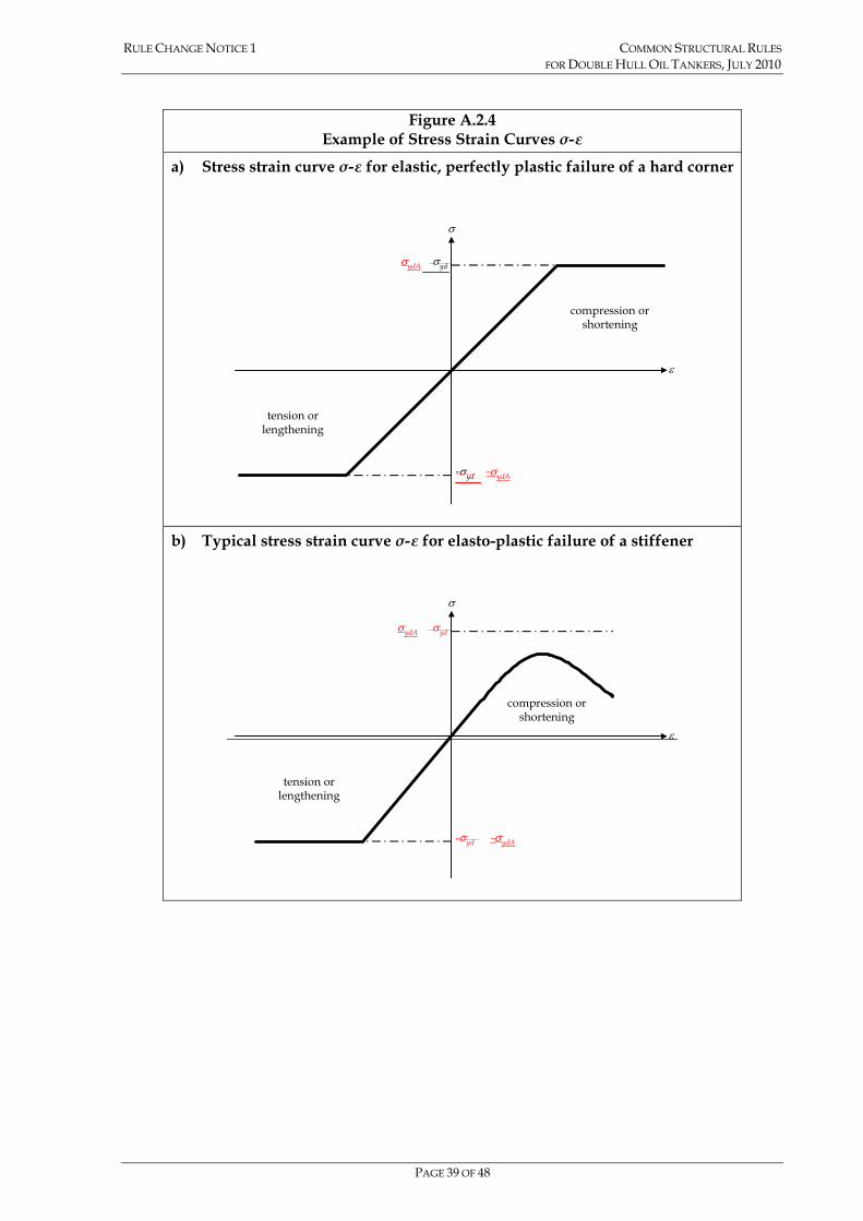
structural elements is to be obtained from the following formula, valid for both positive (compression or shortening) of hard corners and negative (tension or lengthening) strains of all elements (see Figure A.2.4): σ = Φ σyd
σ = Φ σydA
Where:
Φ edge function: Φ = -1 for ε < -1 Φ = ε for -1 < ε < 1 Φ = 1 for ε > 1
ε relative strain:
yd
E
εεε =
εE element strain
ε yd strain corresponding to yield stress in the element:
Eyd
ydσ
ε =
EydA
ydσ
ε =
σyd specified minimum yield stress of the material, in N/mm2
σydA equivalent minimum yield stress of the considered element, in N/mm2
50 50
50 50
ydp p net yds s netydA
p net s net
A AA A
σ σσ − −
− −
+=
+
σydp specified minimum yield stress of the material of the plate, in N/mm2
σyds specified minimum yield stress of the material of the stiffener, in N/mm2
Ap-net50 net sectional area of attached plating, in cm2
As-net50 net sectional area of the stiffener without attached plating, in cm2
Note The signs of the stresses and strains in this Appendix are opposite to those in the rest of the Rules
RULE CHANGE NOTICE 1 COMMON STRUCTURAL RULES FOR DOUBLE HULL OIL TANKERS, JULY 2010
PAGE 39 OF 48
Figure A.2.4
Example of Stress Strain Curves σ-ε
a) Stress strain curve σ-ε for elastic, perfectly plastic failure of a hard corner
σ
σyd
-σyd
compression orshortening
tension orlengthening
ε
σydA
-σydA
b) Typical stress strain curve σ-ε for elasto-plastic failure of a stiffener
σ
ε
-σyd
σyd
tension orlengthening
compression orshortening
σydA
-σydA

RULE CHANGE NOTICE 1 COMMON STRUCTURAL RULES FOR DOUBLE HULL OIL TANKERS, JULY 2010
PAGE 40 OF 48
2.3.4 Beam column buckling 2.3.4.1 The equation describing the shortening portion of the stress strain curve σCR1-ε for
the beam column buckling of stiffeners is to be obtained from the following formula:
⎟⎟
⎠
⎞
⎜⎜
⎝
⎛
+
+= −
−
−−
−
502
50
502
5011 10
10
netnets
netpeffnetsCCR stA
tbAσΦσ N/mm2
Where:
Φ edge function defined in 2.3.3.1
As-net50 net area of the stiffener, in cm2, without attached plating
σC1 critical stress, in N/mm2:
εσ
σσ
εσσσ
εσ
σε
σσ
241
2
11
1
11
1
ydE
E
ydydC
ydE
EC
for
for
>⎟⎟⎠
⎞⎜⎜⎝
⎛−=
≤=
εσ
σσ
εσσσ
εσ
σε
σσ
241
2
11
1
11
1
ydBE
E
ydBydBC
ydBE
EC
for
for
>⎟⎟⎠
⎞⎜⎜⎝
⎛−=
≤=
ε relative strain defined in 2.3.3.1
σE1 Euler column buckling stress, in N/mm2: 4
250
5021 10−
−
−=stfnetE
netEE lA
IEπσ
E modulus of elasticity, 2.06 x 10⁵ N/mm2
IE-net50 net moment of inertia of stiffeners, in cm4, with attached plating of width beff-s
beff-s effective width, in mm, of the attached plating for the stiffener:
0.1for
0.1for
≤=
>=
−
−
pseff
pp
seff
sb
sb
β
ββ
pβ
Ets yd
net
εσ50
=
Ets ydp
net
εσ
50=
s plate breadth, in mm, taken as the spacing between the stiffeners, as defined in Section 4/2.2.1
tnet50 net thickness of attached plating, in mm
AE-net50 net area, in cm2, of stiffeners with attached plating of width beff-p
lstf span of stiffener, in m, equal to spacing between primary support members

RULE CHANGE NOTICE 1 COMMON STRUCTURAL RULES FOR DOUBLE HULL OIL TANKERS, JULY 2010
PAGE 41 OF 48
beff-p effective width, in mm, of the plating:
25.1for
25.1for25.125.22
≤=
>⎟⎟⎠
⎞⎜⎜⎝
⎛−=
−
−
ppeff
ppp
peff
sb
sb
β
βββ
σydB equivalent minimum yield stress of the considered element, in N/mm2
sEnetspEnetpE
sEnetsydspEnetpEydpydB lAlA
lAlA
5050
5050
−−
−−
+
+=
σσσ
ApE-net50 effective area, in cm2
502
50 10 netseffnetpE tbA −−
− =
σydp specified minimum yield stress of the material of the plate, in N/mm2
σyds specified minimum yield stress of the material of the stiffener, in N/mm2
lpE distance, in mm, measured from the neutral axis of the stiffener with attached plate of width, beff-s, to the bottom of the attached plate
lsE distance, in mm, measured from the neutral axis of the stiffener with attached plate of width, beff-s, to the top of the stiffener
2.3.5 Torsional buckling of stiffeners 2.3.5.1 The equation describing the shortening portion of the stress-strain curve σCR2-ε for
the lateral-flexural buckling of stiffeners is to be obtained according to the following formula:
502
50
502
2502 10
10
netnets
CPnetCnetsCR stA
σstσAΦσ −
−
−−
+
+= N/mm2
Where:
Φ edge function defined in 2.3.3.1
As-net50 net area of the stiffener, in cm2, without attached plating
σC2 critical stress, in N/mm2:
εσ
σσ
εσσσ
εσ
σε
σσ
2for
41
2for
22
2
22
2
ydE
E
ydydC
ydE
EC
>⎟⎟⎠
⎞⎜⎜⎝
⎛−=
≤=
εσ
σσ
εσσσ
εσ
σε
σσ
241
2
22
2
22
2
ydsE
E
ydsydsC
ydsE
EC
for
for
>⎟⎟⎠
⎞⎜⎜⎝
⎛−=
≤=
σE2 Euler torsional buckling stress, in N/mm2 σE2=σET

RULE CHANGE NOTICE 1 COMMON STRUCTURAL RULES FOR DOUBLE HULL OIL TANKERS, JULY 2010
PAGE 42 OF 48
σET reference stress for torsional buckling, in N/mm2, defined in Section 10/3.3.3.1, calculated based on gross thickness minus the corrosion addition 0.5tcorr.
ε relative strain defined in 2.3.3.1
s plate breadth, in mm, taken as the spacing between the stiffeners, as defined in Section 4/2.2.1
tnet50 net thickness of attached plating, in mm
σCP ultimate strength of the attached plating for the stiffener, in N/mm2:
25.1for
25.1for25.125.22
≤=
>⎟⎟⎠
⎞⎜⎜⎝
⎛−=
pydCP
pydpp
CP
βσσ
βσββ
σ
25.1for
25.1for25.125.22
≤=
>⎟⎟
⎠
⎞
⎜⎜
⎝
⎛−=
pydpCP
pydppp
CP
βσσ
βσββ
σ
βp coefficient defined in 2.3.4
σydp specified minimum yield stress of the material of the plate, in N/mm2
σyds specified minimum yield stress of the material of the stiffener, in N/mm2
2.3.6 Web local buckling of stiffeners with flanged profiles 2.3.6.1 The equation describing the shortening portion of the stress strain curve σCR3-ε for
the web local buckling of flanged stiffeners is to be obtained from the following formula:
⎟⎟⎠
⎞⎜⎜⎝
⎛
++++
Φ=−−
−−−−
505050
5050503
netffnetwwnet
netffnetweffwnetpeffydCR tbtdst
tbtdtbσσ N/mm2
( )505050
5050503
netffnetwwnet
ydsnetffnetweffwydpnetpeffCR tbtdst
tbtdtb
−−
−−−−
++
++Φ=
σσσ N/mm2
Where:
Φ edge function defined in 2.3.3.1
beff-p effective width, in mm, of the plating, defined in 2.3.4
tnet50 net thickness of plate, in mm
dw depth of the web, in mm
tw-net50 net thickness of web, in mm
bf breadth of the flange, in mm
tf-net50 net thickness of flange, in mm
s plate breadth, in mm, taken as the spacing between the

RULE CHANGE NOTICE 1 COMMON STRUCTURAL RULES FOR DOUBLE HULL OIL TANKERS, JULY 2010
PAGE 43 OF 48
stiffeners, as defined in Section 4/2.2.1 dw-eff effective depth of the web, in mm:
25.1for
25.1for25.125.22
≤=
>⎟⎟⎠
⎞⎜⎜⎝
⎛−=
−
−
wweffw
wwww
effw
dd
dd
β
βββ
βw
Eεσ
td yd
netw
w
50−
Etd yds
netw
w εσ
50−
ε relative strain defined in 2.3.3.1
Ε modulus of elasticity, 2.06 x 10⁵ N/mm2
σydp specified minimum yield stress of the material of the plate, in N/mm2
σyds specified minimum yield stress of the material of the stiffener, in N/mm2
2.3.7 Web local buckling of flat bar stiffeners 2.3.7.1 The equation describing the shortening portion of the stress-strain curve σCR4-ε for
the web local buckling of flat bar stiffeners is to be obtained from the following formula:
⎟⎟⎠
⎞⎜⎜⎝
⎛
+
+=
−−
−−
502
50
4502
504 10
10
netsnet
CnetsCPnetCR Ast
σAσstΦσ
Where:
Φ edge function defined in 2.3.3.1
σCP ultimate strength of the attached plating, in N/mm2, defined in 2.3.5
σC4 critical stress, in N/mm2:
εσ
σσ
εσσσ
εσ
σε
σσ
2for
41
2for
44
4
44
4
ydE
E
ydydC
ydE
EC
>⎟⎟⎠
⎞⎜⎜⎝
⎛−=
≤=
εσ
σσ
εσσσ
εσ
σε
σσ
241
2
44
4
44
4
ydsE
E
ydsydsC
ydsE
EC
for
for
>⎟⎟⎠
⎞⎜⎜⎝
⎛−=
≤=
σE4 Euler buckling stress, in N/mm2: 2
504 160000 ⎟⎟
⎠
⎞⎜⎜⎝
⎛= −
w
netwE d
tσ
ε relative strain defined in 2.3.3.1.

RULE CHANGE NOTICE 1 COMMON STRUCTURAL RULES FOR DOUBLE HULL OIL TANKERS, JULY 2010
PAGE 44 OF 48
As-net50 net area of stiffener, in cm2, see 2.3.5.1
tw-net50 net thickness of web, in mm
dw depth of the web, in mm
s plate breadth, in mm, taken as the spacing between the stiffeners, as defined in Section 4/2.2.1
tnet50 net thickness of attached plating, in mm
σyds specified minimum yield stress of the material of the stiffener, in N/mm2
2.3.8 Buckling of transversely stiffened plate panels 2.3.8.1 The equation describing the shortening portion of the stress-strain curve σCR5-ε for
the buckling of transversely stiffened panels is to be obtained from the following formula:
⎪⎪⎪⎪
⎩
⎪⎪⎪⎪
⎨
⎧
Φ
⎥⎥⎥
⎦
⎤
⎢⎢⎢
⎣
⎡
⎟⎟
⎠
⎞
⎜⎜
⎝
⎛+⎟
⎟
⎠
⎞
⎜⎜
⎝
⎛−+
⎟⎟
⎠
⎞
⎜⎜
⎝
⎛−Φ
=
yd
pstfppstfyd
CR
ls
ls
σ
βββσ
σ
2
22
5
111000
11.025.125.21000
min N/mm2
⎪⎪⎪⎪
⎩
⎪⎪⎪⎪
⎨
⎧
Φ
⎥⎥⎥
⎦
⎤
⎢⎢⎢
⎣
⎡
⎟⎟
⎠
⎞
⎜⎜
⎝
⎛+⎟
⎟
⎠
⎞
⎜⎜
⎝
⎛−+
⎟⎟
⎠
⎞
⎜⎜
⎝
⎛−Φ
=
ydp
pstfppstfydp
CR
ls
ls
σ
βββσ
σ
2
22
5
111000
11.025.125.21000
min N/mm2
Where:
βp coefficient defined in 2.3.4.1
Φ edge function defined in 2.3.3.1
s plate breadth, in mm, taken as the spacing between the stiffeners, as defined in Section 4/2.2.1
lstf stiffener span, in m, equal to spacing between primary support members
σyd specified minimum yield stress of the material, in N/mm2
σydp specified minimum yield stress of the material of the plate, in N/mm2

RULE CHANGE NOTICE 1 COMMON STRUCTURAL RULES FOR DOUBLE HULL OIL TANKERS, JULY 2010
PAGE 45 OF 48
Appendix B – Structural Strength Assessment 2 CARGO TANK STRUCTURAL STRENGTH ANALYSIS
2.4 Application of Loads
2.4.7 Pressure in cargo and ballast tanks
2.4.7.7 The following are to be considered when calculating the static tank pressure in cargo tanks for harbour/tank testing load cases (design combination S) as required by Section 7/Table 7.6.1:
• Maximum setting of pressure relief valve, Pvalve as defined in Section 7/2.2.3.5, of all cargo tanks and, where applicable, maximum hair, as defined in Section 7/2.2.3.2 and Figure 7.2.3, of all cargo tanks in the cargo region are to be considered in the calculation of Pin-test, see Section 7/2.2.3.5.
2.4.7.9 Maximum setting of pressure relief valve, Pvalve, as defined in Section 7/2.2.3.5 are to be considered in design combination S and S+D as required by Section 7/Table 7.6.1.
2.5 Procedure to Adjust Hull Girder Shear Forces and Bending Moments
2.5.1 General 2.5.1.1 The procedure described in this section is to be applied to adjust the hull girder
horizontal bending moment, vertical shear force and vertical bending moment distributions on the three cargo tanks FE model to achieve the required values.
2.5.1.2 Vertical distributed loads are applied to each frame position, together with a vertical bending moment applied to the model ends to produce the required value of vertical shear force at both the forward and aft bulkhead of the middle tank of the FE model, and the required value of vertical bending moment at a section within the length of the middle tank of the FE model. The required values are specified in 2.4.5.
2.5.1.3 A horizontal bending moment is applied to the ends of the model to produce the required target value of horizontal bending moment at a section within the length of the middle tank of the FE model. The required values are specified in 2.4.6.
2.5.2 Shear force and bending moment due to local loads 2.5.2.1 The vertical shear forces generated by the local loads are to be calculated at the
transverse bulkhead positions of the middle tank of the FE model. The maximum absolute shear force at the bulkhead position of the middle tank of the FE model is to be used to obtain the required adjustment in shear forces at the transverse bulkhead, see 2.5.3. The vertical bending moment distribution generated by the local loads is to be calculated along the length of the middle tank of the three cargo tank FE model. The FE model can be used to calculate the shear forces and bending moments. Alternatively, a simple beam model representing the length of the 3-tank FE model with simply supported ends may be used to determine the shear force and bending moment values.
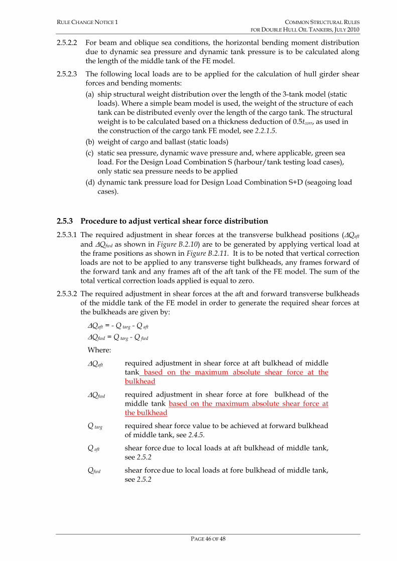
RULE CHANGE NOTICE 1 COMMON STRUCTURAL RULES FOR DOUBLE HULL OIL TANKERS, JULY 2010
PAGE 46 OF 48
2.5.2.2 For beam and oblique sea conditions, the horizontal bending moment distribution due to dynamic sea pressure and dynamic tank pressure is to be calculated along the length of the middle tank of the FE model.
2.5.2.3 The following local loads are to be applied for the calculation of hull girder shear forces and bending moments: (a) ship structural weight distribution over the length of the 3-tank model (static
loads). Where a simple beam model is used, the weight of the structure of each tank can be distributed evenly over the length of the cargo tank. The structural weight is to be calculated based on a thickness deduction of 0.5tcorr, as used in the construction of the cargo tank FE model, see 2.2.1.5.
(b) weight of cargo and ballast (static loads) (c) static sea pressure, dynamic wave pressure and, where applicable, green sea
load. For the Design Load Combination S (harbour/tank testing load cases), only static sea pressure needs to be applied
(d) dynamic tank pressure load for Design Load Combination S+D (seagoing load cases).
2.5.3 Procedure to adjust vertical shear force distribution 2.5.3.1 The required adjustment in shear forces at the transverse bulkhead positions (∆Qaft
and ∆Qfwd as shown in Figure B.2.10) are to be generated by applying vertical load at the frame positions as shown in Figure B.2.11. It is to be noted that vertical correction loads are not to be applied to any transverse tight bulkheads, any frames forward of the forward tank and any frames aft of the aft tank of the FE model. The sum of the total vertical correction loads applied is equal to zero.
2.5.3.2 The required adjustment in shear forces at the aft and forward transverse bulkheads of the middle tank of the FE model in order to generate the required shear forces at the bulkheads are given by:
∆Qaft = - Q targ - Q aft ∆Qfwd = Q targ - Q fwd
Where:
∆Qaft required adjustment in shear force at aft bulkhead of middle tank based on the maximum absolute shear force at the bulkhead
∆Qfwd required adjustment in shear force at fore bulkhead of the middle tank based on the maximum absolute shear force at the bulkhead
Q targ required shear force value to be achieved at forward bulkhead of middle tank, see 2.4.5.
Q aft shear force due to local loads at aft bulkhead of middle tank, see 2.5.2
Qfwd shear force due to local loads at fore bulkhead of middle tank, see 2.5.2

RULE CHANGE NOTICE 1 COMMON STRUCTURAL RULES FOR DOUBLE HULL OIL TANKERS, JULY 2010
PAGE 47 OF 48
Figure B.2.10 Position of Target Shear Force and Required Shear Force Adjustment
at Transverse Bulkhead Positions Target Aft Bkhd Fore Bkhd
Condition BM SF Bkhd
pos SF ∆Qaft SF ∆Qfwd
Bkhd Bkhd BkhdTarget BM(hogging)-Target SF
∆QfwdQaft
Qfwd∆Qaft
Target SF (-ve)
Bkhd
Hog
-ve
Fore
-Qta
rg
-Qta
rg -
Q a
ft
Qta
rg (-
ve)
Qta
rg –
Qfw
d
Bkhd Bkhd Bkhd-Target SF
Target SF (-ve)
Qaft
Qfwd
Target BM(hogging)
∆Qfwd
∆Qaft
Bkhd
Hog
-ve
Fore
-Qta
rg
-Qta
rg –
Qaf
t
Qta
rg (-
ve)
Qta
rg –
Qfw
d
Bkhd Bkhd
-Target SF
Qaft
Qfwd
Target BM(sagging)
∆Qaft
BkhdTarget SF (+ve)
∆Qfwd
Bkhd
Sag
+ve
Fore
-Qta
rg
-Qta
rg -
Qaf
t
Qta
rg (+
ve)
Qta
rg -
Qfw
d
Bkhd Bkhd Bkhd Bkhd
Target BM(sagging)
-Target SF
∆QfwdQaft
Qfwd∆Qaft
Target SF (+ve)
Sag
+ve
Fore
-Qta
rg
-Qta
rg -
Qaf
t
Qta
rg (+
ve)
Qta
rg -
Qfw
d
Note For definition of symbols, see 2.5.3.2.

RULE CHANGE NOTICE 1 COMMON STRUCTURAL RULES FOR DOUBLE HULL OIL TANKERS, JULY 2010
PAGE 48 OF 48
Appendix C – Fatigue Strength Assessment
1.4.4.20 The stress range combination factors, f1, f2, f3 and f4, which are to be applied to the following zones, are given in Tables C.1.2 to C.1.4 Tables C.1.3 to C.1.5: (a) Zone M: Midship region. This zone extends over the full length of all tanks
where the tank LCG lies between 0.35L and 0.8L from AP. (b) Zone A: Aft region. This zone starts at the middle of the tank immediately aft of
Zone M and extends aftwards to include all the aftmost tanks. (c) Zone F: Forward region. This zone starts at the middle of the tank immediately
forward of Zone M and extends forwards to include all the foremost tanks. (d) Zone AT: Aft transition region between Zone M and Zone A. The stress range
combination factors are to be calculated by linear interpolation between the stress range combination factors for Zones M and A.
(e) Zone FT: Forward transition region between Zone M and Zone F. The stress range combination factors are to be calculated by linear interpolation between the stress range combination factors for Zones M and F.
Note Where ballast tanks, centre and wing cargo tanks do not have the same lengths e.g. if slop tank is present, the middle position is to be taken at the middle of the longer tank.
0000

Common Structural Rules for Double Hull Oil Tankers, July 2010
Technical Background for Rule Change Notice 1
(1 July 2010 consolidated edition)
Notes:
(1) These Rule Changes enter into force on 1st July 2012.
(2) The Rule amendments in this document are applicable to the Common Structural Rules for Double Hull Oil Tankers, July 2010.
Copyright in these Common Structural Rules for Double Hull Oil Tankers is owned by:
American Bureau of Shipping Bureau Veritas China Classification Society Det Norske Veritas Germanischer Lloyd Korean Register of Shipping Lloyd's Register Nippon Kaiji Kyokai Registro Italiano Navale Russian Maritime Register of Shipping
Copyright © 2006 The IACS members, their affiliates and subsidiaries and their respective officers, employees or agents are, individually and collectively, referred to in this clause as the ‘IACS Members’. The IACS Members, individually and collectively, assume no responsibility and shall not be liable to any person for any loss, damage or expense caused by reliance on the information or advice in this document or howsoever provided, unless that person has signed a contract with the relevant IACS Member entity for the provision of this information or advice and in that case any responsibility or liability is exclusively on the terms and conditions set out in that contract.

TECHNICAL BACKGROUND COMMON STRUCTURAL RULES FOR RULE CHANGE NOTICE 1 FOR DOUBLE HULL OIL TANKERS, JULY 2010
PAGE 2 OF 36
SECTION 4 - BASIC INFORMATION Section 4/2.6.3.6
1. Background
The proposed amendment is to correct the cross reference.
Section 4/3.2.5.1
1. Background The proposal is to clarify that the requirements for sniped stiffeners are also applicable to structure subjected to sloshing loads. The amendment is also in line with the principle in Section 2/5.4.1.8. The proposed amendment is in line with the answer provided in the IACS CSR Knowledge Centre KC ID: 946:
Question #946: Q1. Is Section 4/3.2.5.1 applicable to sloshing pressure in accordance with Section 8/6.2.4.1 and 8/6.2.5.3? In this connection, please note that our major concern is web stiffeners on the primary support members since there are many such stiffeners with sniped ends. Please also note that the definition of "P" in Section 4/3.2.5.1 refer to Table 8.2.5, Section 8/3.9.2.2 and 8/4.8.1.2 but neither 8/6.2.4.1 nor 8/6.2.5.3. Please clarify. If affirmative, the rule text needs to be updated. Q2. If the above answer is affirmative, please also clarify which "C1" factor is to be used for sloshing pressure (e.g. 1.2 for AC1 or 1.0 for AC2)? Answer #946: A1: The requirements are applicable to sloshing pressure. The Rules will be amended to clarify this. A2: On the basis of the principle in Section 2/5.4.1.8 a C1 factor of C1=1.2 should be utilised.
2. Impact on scantlings There is no impact on scantlings as the Rule change proposal clarifies the application of the requirements.

TECHNICAL BACKGROUND COMMON STRUCTURAL RULES FOR RULE CHANGE NOTICE 1 FOR DOUBLE HULL OIL TANKERS, JULY 2010
PAGE 3 OF 36
Section 4/3.4.1.4
1. Background
Section 4/3.4.1.4 indicates "a soft heel is not required at the intersection with watertight bulkheads, where a back bracket is fitted or where the primary support member web is welded to the stiffener face plate".
In this connection, while the above sentence specifies permissible omission of soft heel at intersection with "watertight bulkheads", the proposal is to apply the same provision for the intersection with ordinary primary support members, where a back bracket is fitted or where the primary support member web is welded to the stiffener face plate.
The proposed amendment is in line with the answer provided in the IACS CSR Knowledge Centre KC ID: 985:
RCP #985:
Section 4/3.4.1.4 indicates "a soft heel is not required at the intersection with watertight bulkheads, where a back bracket is fitted or where the primary support member web is welded to the stiffener face plate".
In this connection, while the above sentence specifies permissible omission of soft heel at intersection with "watertight bulkheads", we presume that the same provision can be also applied for the intersection with ordinary primary support members, where a back bracket is fitted or where the primary support member web is welded to the stiffener face plate, Please note that the last part of the above sentence also indicates "primary support member web is welded to the stiffener face plate", which may not be at "watertight bulkheads".
Please confirm, and update the Rule text, as appropriate. If it should be limited to watertight bulkhead intersection only, please advise the reason.
Answer #985:
We agree with your interpretation. The Rules will be amended at the next opportunity.
2. Impact on scantlings
There is no impact on scantlings as the Rule change proposal clarifies the application of the requirements.

TECHNICAL BACKGROUND COMMON STRUCTURAL RULES FOR RULE CHANGE NOTICE 1 FOR DOUBLE HULL OIL TANKERS, JULY 2010
PAGE 4 OF 36
SECTION 6 - MATERIALS AND WELDING Section 6/1.2.3.1
1. Background
The proposed amendment is to correct the definition of the temperature.
Section 6/Table 6.1.3, category “Special”
1. Background
The proposed amendment is to bring the Rules in line with Table 1 of IACS UR S6 Rev.5.
The proposed amendment is in line with the answer provided in the IACS CSR Knowledge Centre KC ID: 942:
RCP #942:
RCP regarding the material class specified in Table 6.1.3 of CSR Tanker.
In table 6.1.3 of CSR Tanker, deck strakes at longitudinal bulkheads are defined as "SPECIAL".
On the other hand, according to IACS UR S6 Rev. 5, deck strakes at longitudinal bulkheads, excluding deck plating in way of the inner skin bulkheads of double hull ships are defined as "SPECIAL"
Hence, the material class is required to be Class III for deck strakes at longitudinal bulkheads including inner skin bulkhead within 0.4L amidships by CSR Tanker, while it is required to be Class II for deck strakes in way of the inner skin bulkheads of double hull ships within 0.4L amidships by IACS UR S6 Rev.5 because such members are defined as "PRIMARY".
We believe it is reasonable that deck strakes in way of the inner skin bulkheads of double hull ships is defined as "PRIMARY" not "SPECIAL" because such members are located very close to stringer plates and sheer strakes compared to deck plates at other longitudinal bulkheads.
Therefore, we would like to propose that table 6.1.3 be amended so that it is in line with Table 1 of IACS UR S6 Rev.5.
Answer #942:
Your proposal is agreed with and will be considered at the next Rule Change Proposal.
2. Impact on scantlings
There is no impact on scantlings.

TECHNICAL BACKGROUND COMMON STRUCTURAL RULES FOR RULE CHANGE NOTICE 1 FOR DOUBLE HULL OIL TANKERS, JULY 2010
PAGE 5 OF 36
Section 6/2.1.1.2
1. Background
The proposed amendment is to indicate the adoption date of the Performance standard for protective coatings for ballast tanks and void spaces by IMO, and to reference the IACS Unified Interpretation UI SC223 and SC227 for transparent application by IACS members.
2. Impact on scantlings
There is no impact on scantlings.
Section 6/Table 6.1.3, Note 8
1. Background
The proposed amendment is to harmonise the requirements for the engine bed plates between the CSR for Double Hull Oil Tankers and the CSR for Bulk Carriers.
The requirement regarding the application of materials for engine bed plates are not specified in any IACS Unified Requirements. The requirements in CSR BC and OT are based on the requirements of the developing societies behind the CSRs.
Considering pre-CSR service history, plan approval practice, and discussions in the IACS Hull Panel, the following was agreed to be proposed:
Material Class or Grade Rules Thickness
0.4L Outside 0.6L
< 40 mm A/AH A/AH CSR Tanker
> 40 mm B/AH A/AH
CSR Bulker KC ID 711
- Class I
CSR Bulker Proposal RCP2
within 0,6L
Class I A/AH
< 30 mm A/AH A/AH Harmonised CSR > 30 mm B/AH A/AH
2. Impact on scantlings
There is no impact on scantlings.
Section 6/Figure 6.3.1
1. Background
The proposed amendment is to clarify how the 3 metre line from top of tank should be measured.
2. Impact on scantlings
There is no impact on scantlings as the purpose of the Rule change proposal is to clarify top of tank and the “3m line”.

TECHNICAL BACKGROUND COMMON STRUCTURAL RULES FOR RULE CHANGE NOTICE 1 FOR DOUBLE HULL OIL TANKERS, JULY 2010
PAGE 6 OF 36
Section 6/4.1.2.3
1. Background
The proposed amendment is to provide clarification for the requirements for in-place boring and block boring method. This proposed amendment is based on questions raised by shipyards which traditionally perform block boring.
The proposed amendment is in line with the answer provided in the IACS CSR Knowledge Centre KC ID 1083:
Question #1083:
Section 6/4.1.2.3(h) requires "The final boring out of the propeller boss and stern frame, skeg or solepeice fit-up and alignment of the rudder, pintles and axles, are to be carried out after completing the major part of the welding of the aft part of the ship. The contact between the conical surfaces of the pintles, rudder stock and rudder axles are to be checked before the final mounting."
We note that the first sentence of this comes from the LR Rules Pt. 3, Ch. 1, Sec.8.2.3 (July 2001 Edition).
Regarding the first sentence, "The final boring out of the propeller boss and stern frame, skeg or solepeice fit-up and alignment of the rudder, pintles and axles, are to be carried out after completing the major part of the welding of the aft part of the ship." We note that one major shipbuilder carries out shaft alignment work in block stage and has done this successfully for many years.
We contend the above be open to alternative procedures. Further such items as indicated in the requirements "The final boring out of the propeller boss and stern frame, skeg or solepeice fit-up and alignment of the rudder, pintles and axles, are to be carried out after completing the major part of the welding of the aft part of the ship. The contact between the conical surfaces of the pintles, rudder stock and rudder axles are to be checked before the final mounting.", are fabrication issues that need not be specifically addressed in the Common Structural Rules. It is believed that this text should be removed from the Rules or that the Rules clearly permit alternative procedures for confirming such alignment.
Your prompt reply on this matter would be highly appreciated.
Answer #1083:
The Rules state that alignment should be carried out after completing the major part of the welding of the aft part of the ship. An alternative procedure to the shaft alignment may be accepted and should be reviewed by the Classification Society. As for the pintle this is a local system which would be relatively unaffected by block assembly and floating out provided all the work in the block has been completed.
2. Impact on scantlings
There is no impact on scantlings.

TECHNICAL BACKGROUND COMMON STRUCTURAL RULES FOR RULE CHANGE NOTICE 1 FOR DOUBLE HULL OIL TANKERS, JULY 2010
PAGE 7 OF 36
SECTION 7 - LOADS Section 7/7.6.1
1. Background
A minimum setting of pressure relief valve is given in the Rules as 25 kN/m2. The minimum value is applied in design load combination “S” only.
The Rules are not clear how to apply a proposed setting of the pressure relief valve value higher than the Rule minimum. The proposal clarifies this aspect.
The proposed amendment is in line with the answer provided in the IACS CSR Knowledge Centre KC ID: 1110:
Interpretation Request #1110:
As per Table 7.6.1 and Appendix B/2.4.7.7 of the Rules with the referenced section 7/2.2.3.5, we understand that the relief valve pressures are subject to static conditions only for local scantlings & FE analysis requirements respectively, i.e setting pressure relief valve does not need to be considered in static + dynamic conditions. We understand that the same is true even though the designed setting pressure of relief value is higher than 25KN/m2. In that case, does any dynamic effect of the excessive pressure have to be considered? For instance, if the setting of pressure relief is 70 KN/m2, do we have to consider the additional 45 KN/m2 in S+D conditions?
Answer #1110:
The Rule minimum relief valve pressure is Pvalve=25kN/m2. Yes; the additional pressure above the Rule minimum is to be considered so pressure relief valve of 70 KN/m2 for "S" and 45 KN/m2 for "S+D" conditions.

TECHNICAL BACKGROUND COMMON STRUCTURAL RULES FOR RULE CHANGE NOTICE 1 FOR DOUBLE HULL OIL TANKERS, JULY 2010
PAGE 8 OF 36
SECTION 8 - SCANTLING REQUIREMENTS Section 8/1.1.2.2
1. Background
The requirement of not having any dry or clean ballast for the seagoing homogeneous loading condition at scantling draft only applies to the departure condition. Ballast may be used in mid-voyage and arrival conditions to correct the trim due to reduction of fuel oil.
The proposed amendment is in line with the answer provided in the IACS CSR Knowledge Centre KC ID: 947:
RCP #947:
With regard to the loading conditions, including both departure and arrival, to be included in the Loading Manual, CSR Tanker Sec.8/1.1.2.2(a) specifies that homogeneous loading conditions at the scantling draft shall not include the filling of dry and clean ballast tanks.
However, paragraph 1.1.2.c of the Technical Background for Section 8/1 of CSR Tanker is as follows:
“The requirement of not having any dry or clean ballast for the seagoing homogeneous loading condition at scantling draft only applies to the departure condition. Ballast may be used in mid-voyage and arrival conditions to correct the trim due to reduction of fuel oil”
Therefore, the application of the requirement is not clear because of the discrepancy between the current requirement and the Technical Background.
Our understanding is that it is appropriate to apply the requirement only to the departure condition according to the Technical Background. Please confirm.
If necessary, please amend the rule’s text to clarify this.
Answer #947:
Your proposal has been agreed with. The Rules will be amended at the next opportunity.
2. Impact on scantlings
There is no impact on scantlings as the purpose of the Rule change proposal is to clarify the loading conditions to be included in the Loading Manual.

TECHNICAL BACKGROUND COMMON STRUCTURAL RULES FOR RULE CHANGE NOTICE 1 FOR DOUBLE HULL OIL TANKERS, JULY 2010
PAGE 9 OF 36
Section 8/1.2.2.2
1. Background
The proposed amendment is to correct the cross reference.
Section 8/1.3.2.2
1. Background
The proposed amendment is to correct the unit of q1-net50.
Section 8/1.3.4.1
1. Background
The proposed amendment is to correct a misprint.
Section 8/1.6.3.1
1. Background The modification is proposed to apply the varying allowable stress along the ship length for the calculation of vertical extent of higher strength steel, instead of “190/k”. In case of checking the vertical extent of higher strength steel at 0.1L (or 0.9L), “140/k”, not “190/k”, would be applied. This is consistent with the intention of the Rules; the permissible hull girder stresses are given in Table 8.1.3. The proposed amendment is in line with the answer provided in the IACS CSR Knowledge Centre KC ID: 909:
Interpretation Request #909: 8/1.6.3 Vertical extent of higher strength steel: We have been checking this requirement even for outside of 0.4L area. However, since permissible hull girder bending stress for outside 0.4L area is not 190/k as shown in Table 8.1.3, we checked vertical extent of higher strength steel zone modifying the formula of 190/k1 in 8/1.6.3.1 with the permissible hull girder bending stress at the check point required in Table 8.1.3. Please clarify and change the rule if it is necessary. Answer #947: For the application of 8/1.6.3.1, the permissible hull girder bending stress for outside 0.4L amidships is to be in accordance with the Table 8.1.3. We will update the Rules to clarify the application.
2. Impact on scantlings
There is no impact on scantlings as the proposal is in line with intention of the Rules.
TECHNICAL BACKGROUND COMMON STRUCTURAL RULES FOR RULE CHANGE NOTICE 1 FOR DOUBLE HULL OIL TANKERS, JULY 2010
PAGE 10 OF 36
Section 8/2.5.7.9 1. Background Corrugated bulkheads are generally utilised as the boundary between cargo tanks of small and medium sized product or chemical tankers. The corrugation provides benefits such as simplified cleaning which is highly desirable due to the operational profile of these vessel types. The last decade has seen significant innovation in the application of corrugated bulkheads to tanker design. In particular the use of corrugated bulkheads has extended to Aframax size and the size of tankers where corrugated bulkheads are fitted without bulkhead stools has also increased. The complexity of structural configuration and difficulties of manufacture can lead to significant defects occurring which may be costly to repair. Particularly for the connection of corrugated bulkheads at the inner bottom or hopper plating the special consideration need to be given to the use of special material with specified through thickness properties considering the potential lamellar tearing problem. Lamellar tearing can be caused by strain in the through-thickness direction that arises from the shrinkage of the weld metal as it cools. It is generally increased where free movement is restrained, as is the case for the connection between corrugated bulkheads and inner bottom plates. The heavier the weld, the greater is the susceptibility to lamellar tearing. Lamellar tearing will normally occur at the new building stage, but it can not be detected fully until the defects have propagated to the surface due to imposed stress during welding in production stage or operation with actual cargo loads.
2. Impact on scantlings
There is no impact on scantlings as the proposal is mandating the use of Z-quality steel in areas with high strains in the thickness direction.

TECHNICAL BACKGROUND COMMON STRUCTURAL RULES FOR RULE CHANGE NOTICE 1 FOR DOUBLE HULL OIL TANKERS, JULY 2010
PAGE 11 OF 36
Section 8/Table 8.2.3 1. Background Table 8.2.3 provides requirements for bulkheads with no lower stool. For bulkheads with no lower stool further investigations and service feedback highlighted that the coefficients for the bending moment distribution are not satisfactory. An investigation was carried out covering: • Bending moments based on prescriptive requirements were compared with BM
calculated from FE results for 3 different bulkheads • Maximum S+D FE condition (A4-5A) was compared with prescriptive requirements
applicable for S+D pressures • FE results for L/Bhd. 1 and T/Bhd. 2 are based on actual project with variable thickness
along the height (see figure below) • FE results for L/Bhd. 3 are based on actual project with constant thickness along the
height
Three vertically corrugated bulkheads without stool tanks have been considered, one transverse bulkhead with variable thickness, and two longitudinal bulkheads. One of the longitudinal bulkheads has variable thickness and one has constant thickness over the height. There is significant disagreement between bending moment distribution obtained from the current prescriptive requirements versus values calculated by FE analysis, especially at the ends. The proposed update and a simple beam expression give good fit with the cases with variable thickness, but for the case with constant thickness these expressions over predict the bending moment at lower end (30%) and under predicts the bending moment at midspan (-12%). Three cases or vertically corrugated bulkheads are applied, of which this comparison covers type C: A) Bulkheads with upper stool and lower stool B) Bulkheads with lower stool only C) Bulkheads without stool The proposed updated bending moment coefficients gives good fit for bulkheads of type C with variable thickness.

TECHNICAL BACKGROUND COMMON STRUCTURAL RULES FOR RULE CHANGE NOTICE 1 FOR DOUBLE HULL OIL TANKERS, JULY 2010
PAGE 12 OF 36
2. Impact on scantlings A consequence assessment has been carried, for the ship detailed in Table 1, and results shown in the tables below: Transverse vertically corrugated bulkhead without lower and upper stools.
• Table 2: Input data • Table 3: Results
Longitudinal vertically corrugated bulkhead without lower and upper stools • Table 4: Input data • Table 5: Results
Table 1 Ship Data Ship length 150 m
Ship depth 15000 mm
Corrugation flange a 1200 mm
Corrugation depth d 1250 mm
Double bottom height at ship's side 1950 mm
Double bottom height at C.L. 1800 mm
Camber at ship C.L. 550 mm Table 2 Input data – Transverse vertically corrugated bulkhead without lower and upper stools t gross 24 mm Corrosion allowance 2.5 mm Projection of the web 500 mm Corrugation length at ship's side 13.05 m Corrugation length at C.L. 13.75 m Corrugation length used in the calculation 13.75 m corrugation length at ship's side Pressure at lower end p l 383.54 MPa the cargo density is 1.85 t/m3 Pressure at upper end p u 26.33 Mpa the cargo density is 1.85 t/m3 Mean pressure p 204.94 MPa the cargo density is 1.85 t/m3 Yield stress sy 315 MPa Modulus of Elasticity E 206000 MPa Cs-cg 0.90 - for lower end Cs-cg 0.77 - for midspan Adt 0 bdk 0

TECHNICAL BACKGROUND COMMON STRUCTURAL RULES FOR RULE CHANGE NOTICE 1 FOR DOUBLE HULL OIL TANKERS, JULY 2010
PAGE 13 OF 36
Table 3 Results – Transverse vertically corrugated bulkhead without lower and upper stools t offered net 21.5 mm spacing s 1700 mm web c 1346.29 mm offered net SM 22155 cm3 Coefficient β 2.18 - Coefficient Ce 0.7685 - Coefficient for lower end C1 1.0 - Coefficient for midspan Cm1 0.75 - B.M. at lower end Mcg (Current) 3293 kNm B.M. at lower end Mcg (Proposal) 5489 kNm B.M. at midspan Mcg (Current) 5269 kNm B.M. at midspan Mcg (Proposal) 4117 kNm SM required at lower end (Current) 11617 cm3 SM required at lower end (Proposal) 19362 cm3 SM required at midspan (Current) 21768 cm3 SM required at midspan (Proposal) 17006 cm3 SM offered net / SM required 1.3028 - required t 18.79 mm NOTES: • Cl calculated by the equation Cl = a1-b1(Adt/bdk)0.5 • Cm1 Calculated by the equation Cm1= am1-bm1(Adt/Bdk)0.5 • Offered net SM calculated by the formula SM = d (3atf + ctw)/6 • min Cm1 = 0.60 • min Cl = 0.55 • In this case Adt = 0 because there is no deck box • If t f = t w = t , the required t is calculated by the formula: • t = 6SM / [d (3a+c)]

TECHNICAL BACKGROUND COMMON STRUCTURAL RULES FOR RULE CHANGE NOTICE 1 FOR DOUBLE HULL OIL TANKERS, JULY 2010
PAGE 14 OF 36
Table 4 Input data – Longitudinal vertically corrugated bulkhead without lower and upper stools t gross 24 mm Corrosion allowance 2.5 mm Projection of the web 500 mm Corrugation length at C.L. 13.75 m Corrugation length used in the calculation 13.75 m corrugation length at ship's side Pressure at lower end p l 377.45 MPa the cargo density is 1.85 t/m3 Pressure at upper end p u 41.77 Mpa the cargo density is 1.85 t/m3 Mean pressure p 209.61 MPa the cargo density is 1.85 t/m3 Yield stress sy 315 MPa Modulus of Elasticity E 206000 MPa Cs-cg 0.90 - for lower end Cs-cg 0.73 - for midspan Adl 0 ldk 0
Table 5 Results – Longitudinal vertically corrugated bulkhead without lower and upper stools t offered net 21.5 mm spacing s 1800 mm web c 1346.29 mm offered net SM 23499 cm3 Coefficient β 2.36 - Coefficient Ce 0.728 - Coefficient for lower end C3 0.9 - Coefficient for midspan Cm3 0.85 - B.M. at lower end Mcg (Current) 3567 kNm B.M. at lower end Mcg (Proposal) 5350 kNm B.M. at midspan Mcg (Current) 5355 kNm B.M. at midspan Mcg (Proposal) 5053 kNm SM required at lower end (Current) 12681 cm3 SM required at lower end (Proposal) 18871 cm3 SM required at midspan (Current) 23353 cm3 SM required at midspan (Proposal) 22033 cm3 SM offered net / SM required 1.0665 - required t 20.16 mm NOTES: • C3 calculated by the equation C3 = a3-b3(Adl/ldk)0.5 • Cm3 calculated by the equation Cm3= am3-bm3(Adl/ldk)0.5 • Offered net SM calculated by the formula SM = d (3atf + ctw)/6 • min Cm3 = 0.60 • min C3 = 0.55 • In this case Adl = 0 because there is no deck box • If t f = t w = t , the required t is calculated by the formula:
t = 6SM / [d (3a+c)]

TECHNICAL BACKGROUND COMMON STRUCTURAL RULES FOR RULE CHANGE NOTICE 1 FOR DOUBLE HULL OIL TANKERS, JULY 2010
PAGE 15 OF 36
Section 8/6.3.7.5 1. Background The proposed amendment is to make an editorial amendment.
Section 8/6.4.5.1, 6.4.7.5 1. Background The proposed amendment is to correct the cross reference.
TECHNICAL BACKGROUND COMMON STRUCTURAL RULES FOR RULE CHANGE NOTICE 1 FOR DOUBLE HULL OIL TANKERS, JULY 2010
PAGE 16 OF 36
SECTION 9 - DESIGN VERIFICATION Section 9/1.1.1.2
1. Background In the current CSR for Tanker Rules the hull girder ultimate strength requirements are to be applied within 0.4L amidships. In the CSR for Bulk Carriers the same requirements is applicable to the entire ship. The Rules stipulate in paragraph 1.1.1.3 that “the plate and stiffeners may be gradually reduced towards the local requirements at the ends”. Recognising the difficulty in tapering ultimate strength requirements for plate and stiffeners, and considering that currently the tapering procedure is only applicable for (side shell and deck) plating thickness we are proposing to apply the hull girder ultimate strength requirements to the entire vessel.
2. Impact on scantlings
The bending moments are greatest within the 0.4L amidships, so it is essential that this region is evaluated for ultimate strength. Outside the 0.4L amidships the bending moments taper towards the ends and likewise the strength of the cross section decrease as the hull narrows towards the ends.
If the longitudinal stiffening is maintained outside the 0.4L there will be no or minimal impact considering that the bending moments tapers outside 0.4L.
If there is some transversely stiffened plates there may be a small localised impact considering the reduced ultimate strength capacity of transversely stiffened plates.
Section 9/2.3.1.1
1. Background
Section 9/2.3.1.1(e) requires fine mesh analysis for typical conventional arrangement:
"(e) end brackets and attached web stiffeners of typical longitudinal stiffeners of double bottom and deck, and adjoining vertical stiffener of transverse bulkhead."
Similarly in Appendix B/Figure B.3.3 shows the areas that require fine mesh analysis in way of deck, inner bottom and bottom longitudinal and transverse bulkhead vertical stiffeners.
Feedback has highlighted that the paragraph together with the figure is being interpreted in such a way that fine mesh analysis is not required where longitudinal stiffeners are fitted above the deck.
The proposed amendment is in line with the answer provided in the IACS CSR Knowledge Centre KC ID: 924:
Interpretation request #924:
Regarding over deck longitudinal stiffening.
Rule reference Section 9/2.3.1.1(e) requires fine mesh analysis for typical conventional arrangement:
"(e)end brackets and attached web stiffeners of typical longitudinal stiffeners of double bottom and deck, and adjoining vertical stiffener of transverse bulkhead."
Does the same requirement apply to over deck longitudinal stiffening?

TECHNICAL BACKGROUND COMMON STRUCTURAL RULES FOR RULE CHANGE NOTICE 1 FOR DOUBLE HULL OIL TANKERS, JULY 2010
PAGE 17 OF 36
Answer #924:
We can confirm that over deck longitudinals are to be investigated by local fine mesh structural analysis.
2. Impact on scantlings
There is no impact on scantlings as the purpose of the Rule change proposal is to clarify the fine mesh requirements and that longitudinals fitted above deck are to be treated in a similar manner to conventional deck longitudinals (under deck).

TECHNICAL BACKGROUND COMMON STRUCTURAL RULES FOR RULE CHANGE NOTICE 1 FOR DOUBLE HULL OIL TANKERS, JULY 2010
PAGE 18 OF 36
Section 9/2.4.5.5
1. Background
In calculating the vertical shear force distribution from the local loads applied to the FE model, there is a step in the vertical shear force at a transverse bulkhead position due to the weight of the transverse bulkhead structure.
The Rules are not clear which shear force value (i.e. maximum or minimum) should be used as a basis to determine the adjustment required to meet the target value.
The proposed amendment to the Rules is to clarify the application of this requirement and to ensure uniform application.
The proposed amendment is in line with the answer provided in the IACS CSR Knowledge Centre KC ID: 953:
Interpretation request #953:
Appendix B, 2.5, 2.5.1.2 and 2.5.3.2
In calculating the vertical shear force distribution from the local loads applied to the FE model, it is noted that there is a step in the vertical shear force at a transverse bulkhead postion due to the weight of the transverse bulkhead structure. It is not clear which shear force value (i.e. maximum or minimum) should be used as a basis to determine the adjustment required to meet the target value.
Answer #953:
The vertical distribution loads are to be applied to produce the required shear force (Qtarg) at both the forward and aft bulkheads of the middle tank of the FE model. It is to be noted that the required adjustment shear forces (∆Qfwd and ∆Qaft) are the same at the forward and aft bulkheads if the FE model is symmetrical about mid-position of the middle tank, i.e. fore and aft tanks of the FE model is the same length and arrangement.
The adjustment shear forces (∆Qfwd and ∆Qaft) should be based on the maximum (absolute) shear force due to local loads at the bulkhead location. The reasons for this choice are as follows:
(1) The shear force after adjustment will not exceed the required value. If the minimum (absolute) shear force due to local loads is used as a basis for deriving the adjustment shear force then the final shear force will exceed the required value at certain locations
(2) The areas with high shear stress are the elements located forward and aft of the transverse bulkheads. Among these areas, the area forward of the transverse bulkhead in way of the transverse bulkhead stringers has highest shear stress
(3) The intention is that (a) sagging case (+ve shear force at forward bulkhead) covers the forward region of the forward bulkhead and aft region of the aft bulkhead and (b) hogging case (-ve shear force at forward bulkhead) covers the forward region of the aft bulkhead and aft region of the forward bulkhead. The scantlings in way of the bulkheads are to be based on the maximum from both bulkhead positions. See attached Figures.
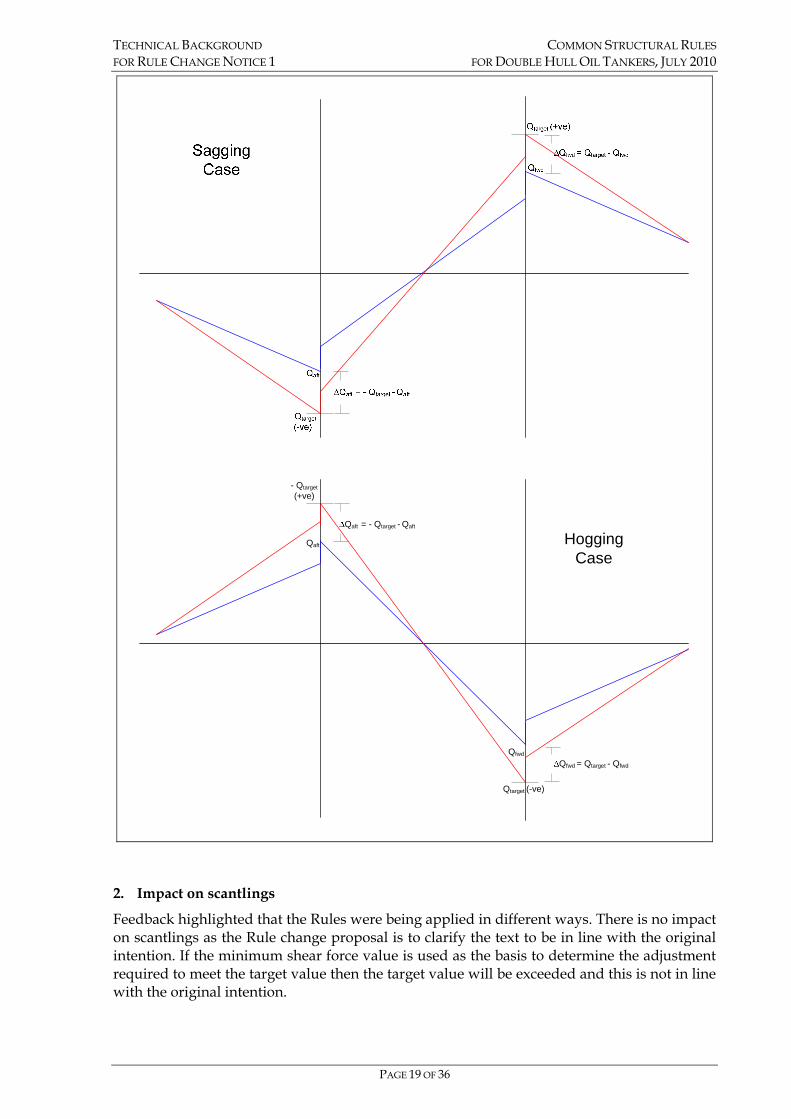
TECHNICAL BACKGROUND COMMON STRUCTURAL RULES FOR RULE CHANGE NOTICE 1 FOR DOUBLE HULL OIL TANKERS, JULY 2010
PAGE 19 OF 36
Qfwd = Qtarget - Qfwd
Qfwd
Qaft = - Qtarget - Qaft
Qaft
Qtarget (-ve)
- Qtarget(+ve)
Hogging Case
2. Impact on scantlings
Feedback highlighted that the Rules were being applied in different ways. There is no impact on scantlings as the Rule change proposal is to clarify the text to be in line with the original intention. If the minimum shear force value is used as the basis to determine the adjustment required to meet the target value then the target value will be exceeded and this is not in line with the original intention.

TECHNICAL BACKGROUND COMMON STRUCTURAL RULES FOR RULE CHANGE NOTICE 1 FOR DOUBLE HULL OIL TANKERS, JULY 2010
PAGE 20 OF 36
SECTION 10 - BUCKLING AND ULTIMATE STRENGTH Section 10/1.1.1.4
1. Background
The proposed amendment is to correct the cross reference.

TECHNICAL BACKGROUND COMMON STRUCTURAL RULES FOR RULE CHANGE NOTICE 1 FOR DOUBLE HULL OIL TANKERS, JULY 2010
PAGE 21 OF 36
SECTION 11 – GENERAL REQUIREMENTS Section 11/Table 11.1.6
1. Background
In CSR Tanker Section 11/1.4.10.1, the coefficient "C4" for "unprotected front" is specified only up to 3rd tier, and is not specified for higher tiers than the 3rd tier.
The proposed amendment is to specify “C4” for tiers above 3rd tier.
The proposed amendment is in line with the answer provided in the IACS CSR Knowledge Centre KC ID: 882:
Question #882:
In CSR Tanker Section 11/1.4.10.1, the coefficient "C4" for "unprotected front" is specified only up to 3rd tier, and is not specified for higher tiers than the 3rd tier. In this connection, since this coefficient for side and aft is specified for "all" tiers, it is presumed that the current text "unprotected front, 3rd tier" should read as "unprotected front, 3rd tier and above". Please confirm.
Answer #882:
Yes, the rule text will be revised accordingly.
2. Impact on scantlings
There is no impact on scantlings as the Rule change proposal clarifies the application of the requirements.
Section 11/Figure 11.1.3
1. Background
The ship length defined by the International Convention on Load Lines (ILLC) is symbolized as LL in CSR for Tankers. On the other hand, length defined as the ship length by CSR for Tankers is symbolized as L.
The requirements based on ILLC stipulated in CSR are proposed amended to LL.
The proposed amendment is in line with the answer provided in the IACS CSR Knowledge Centre KC ID: 868:
RCP #868:
The ship length defined by the International Convention on Load Lines (ILLC) is symbolized as "LLL" in CSR for Bulkers and "LL" in CSR for Tankers. On the other hand, length defined as the ship length by CSR for Bulkers and for Tankers is symbolized as "L". Having reviewed the requirements based on ILLC stipulated in CSR, we consider that some of "L"s should be replaced by either "LLL" or "LL". For your easy reference, the "L"s that could be found by our review are as follows: CSR for Bulkers: - Ch2 Sec2 [5.1.1],[5.1.2],[5.1.4],[5.1.5],[Figure 1] and [Figure 2] - Ch9 Sec6 [4.2.1] CSR for Tankers: - Sec11 [Figure 11.1.3] Please correct the above editorial error.

TECHNICAL BACKGROUND COMMON STRUCTURAL RULES FOR RULE CHANGE NOTICE 1 FOR DOUBLE HULL OIL TANKERS, JULY 2010
PAGE 22 OF 36
Answer #868: CSR/Bulk Carriers: A clear difference must be made between CSR length and ILLC length. For the sake of the reading, the CSR rule length as defined in Ch.1 Sec.4 [3.1.1] is kept as L and the freeboard length (from ILLC) is kept as LLL (the 2 last "L" are subscripted). A corrigenda will be issued to correct the typos. CSR/Tankers:
We agree that length L should replaced with length LL in the CSR for Tankers, Section 11/Figure 11.1.3.
2. Impact on scantlings
There is no impact on scantlings due to this change.
Section 11/4.1.1.1
1. Background
The proposed modification is to clarify the Rule with regards to screens or bulwarks of 1.5 metres or higher. This text has inadvertently been omitted when included from IACS UR A1.
The proposed amendment is in line with the answer provided in the IACS CSR Knowledge Centre KC ID: 775:
Interpretation Request #775: The formula for Equipment Numbers of CSR_Bulk Carrier and CSR_Tankers are not different from each other. But meanings of symbol ‘h’ in formula are different from each other.(See attach files) In case of CSR_Bulk Carriers, meaning of ‘h’ is similar to that of IACS UR A1.(Screens or bulwarks 1.5 m or more in height are to be regarded as parts of houses when determining h.) But in case of CSR_Tankers, text related with screens or bulwarks 1.5 m or more in height is not existed. We need common interpretation for continuity of CSR Rules. Answer #775:
CSR Tankers should be in line with UR A1. We will update the rules accordingly.
2. Impact on scantlings
There is no impact on scantlings due to this change.
Section 11/5.1.5.1
1. Background
The proposed amendment is for testing of butt weld erection joints which are made by automatic and FCAW semi-automatic welding. The matter of tank testing is covered by IACS Unified Requirement S14 and the wording in this UR for leak testing states that leak testing is to be carried out on all fillet weld connections …… excepting welds made by automatic processes.
This wording is similar to the wording of CSR Bulk Carriers Chapter 11, Section 3, 2.2.6.
The proposed amendment is to amend the text to follow the IACS UR S14 and harmonised with CSR Bulk Carriers.
The proposed amendment is in line with the answer provided in the IACS CSR Knowledge Centre KC ID: 957:

TECHNICAL BACKGROUND COMMON STRUCTURAL RULES FOR RULE CHANGE NOTICE 1 FOR DOUBLE HULL OIL TANKERS, JULY 2010
PAGE 23 OF 36
RCP #957:
The requirement for testing of butt weld erection joints which are made by automatic and FCAW semi-automatic welding are a little misleading.
The matter of tank testing is covered by IACS Unified Requirement S14 which all societies are supposed to follow and the wording in this UR for leak testing states that leak testing is to be carried out on all fillet weld connections …… excepting welds made by automatic processes.
This wording is similar to the wording of CSR Bulk Carriers Chapter 11, Section 3, 2.2.6.
We propose that the text is amended to follow the IACS UR S14 and harmonised with CSR BC.
Answer #957:
Your proposal is agreed with.
2. Impact on scantlings
There is no impact on scantlings.
Section 11/Table 11.5.1
1. Background
The proposed amendment is for the footnote [1] to be applicable to Fuel Oil Bunker tanks.
The main requirement of Table 11.5.1 requires structural testing for all tanks of given categories, and the footnote [1] initially accepts leak or hydro-pneumatic testing, provided at least one tank for each type is structurally tested. However, the required structural testing of one tank of each type is then waived for subsequent vessels in a series of identical new buildings unless the Surveyor deems the repetition necessary.
In some cases the structural testing is to be in accordance with the requirements of the individual classification society.
Structural testing is for proving the strength of the structure as built. It is not a higher order tightness test.
The option to limit the structural testing to one tank of each type, is based on the understanding that the design approval, in combination with the site inspection during construction ensures a homogenous strength standard and construction quality. Consequently the structural test result obtained for one tank of a type is seen as an effective proof of the strength of the other tanks of the same type and the leak testing is sufficient test for tightness.

TECHNICAL BACKGROUND COMMON STRUCTURAL RULES FOR RULE CHANGE NOTICE 1 FOR DOUBLE HULL OIL TANKERS, JULY 2010
PAGE 24 OF 36
APPENDIX A – HULL GIRDER ULTIMATE STRENGTH 1. Background
The current Rules for the hull girder ultimate strength calculation are not clear regarding the following cases;
• Where plate members are stiffened by non-continuous longitudinal stiffeners, how should the non-continuous stiffeners be considered?
• Where openings are provided in stiffened plate elements, how should the openings be considered?
• Where attached plating is made of steels having different thicknesses and/or yield stresses, which kind of thickness and/or yield stress should be used?
• Where attached plating and stiffeners are made of steels having different yield stresses, how should the load-end shortening curves be calculated?
The proposed rule changes are for the clarification of the rule requirement and in line with the modifications to Chapter 5/Appendix 1 in CSR Bulk Carrier RCN1 to July 08.
The ways to consider non-continuous stiffeners and openings are specified and formulas for calculating average thickness and average yield stress of attached plating with more than two different thicknesses and/or yield stresses are added. And, the calculation methods of load-end shortening curves are specified for the case in which the yield stress of attached plating is different from stiffeners.
In case of stiffened panels with different yield stresses between attached plates and stiffeners, load-end shortening curves are to be separately calculated for the stiffeners and the attached plates, i.e. the method is similar to the ‘weighted average method on area’ in consideration of the net area of stiffeners and attached plates because this approach is very simple and practicable.
This approach, however, may sometimes produce a smaller ultimate strength in terms of beam column buckling compared with the results of non-linear FEA when the yield stress of stiffeners is less than attached plates, because the area of such attached plates is greater than the stiffeners.
This underestimation of the load-end shortening curves for beam column buckling of such stiffened panel can be resolved by using the first moment of the panel. For other failure modes besides beam column buckling, load-end shortening curves can be calculated by using the yield stress of stiffeners and attached plates, respectively.
A detailed verification of the above methods is described in the Annex.

TECHNICAL BACKGROUND COMMON STRUCTURAL RULES FOR RULE CHANGE NOTICE 1 FOR DOUBLE HULL OIL TANKERS, JULY 2010
PAGE 25 OF 36
2. Summary of Rule Changes
Appendix A/2.2.2.4 Note
For the case in which one side panel of stiffener is longitudinally stiffened and the other panel is transversely stiffened, additional Note is made in order to clarify the effective breadth of attached plating for the stiffener.
Appendix A/2.2.2.5 & 2.2.2.6 For the hull girder ultimate strength calculation, it is clarified how to consider non-continuous stiffener and opening in the plate panel.
Appendix A/2.2.2.7 In case that attached plating consists of more than two different thicknesses and/or yield stresses, the representative thickness and/or yield stress of the attached plating is specifically defined by providing new formulas and figure, which are depicting average thickness and average yield stress based on the proportion of cross sectional area.
Appendix A/2.3.1.2 & 2.3.1.3 For the hull girder ultimate strength calculation, it is clarified how to consider non-continuous stiffener and opening in the plate panel.
Appendix A/2.3.3 to 2.3.8 In case that attached plating and stiffener consist of steels having different yield stresses, it is specifically explained how the load-end shortening curves should be calculated. To be concrete, the concept of equivalent minimum yield stress is newly introduced and load-end shortening curves, which are to be separately calculated for the stiffener and the attached plating, are specified. Furthermore, related formulas and notations are added or modified.
3. Impact on scantlings
There is no impact on scantlings due to this change.
(It is possible that the area deduction due to non-continuous stiffener and/or opening, if any, causes a slight increase of scantling, but it is negligible.)

TECHNICAL BACKGROUND COMMON STRUCTURAL RULES FOR RULE CHANGE NOTICE 1 FOR DOUBLE HULL OIL TANKERS, JULY 2010
PAGE 26 OF 36
Annex Evaluation method of the load end shortening curve for stiffened panel where
the attached plate and stiffener are made of steel having different yield stresses 1. Introduction The evaluation methodology of hull girder ultimate strength in CSR-BC is based on Smith’s method. In cases where any attached plates and stiffeners are made of steel having different yield stresses, the procedures and formulae for load end shortening curves are not described in the current Rules. The following two methods to deal with such elements were considered.
(1) Using lower yield stresses. (2) Considering plate elements and stiffener elements to be separate elements, and calculating the
load-end shortening curves for the stiffener and the attached plating separately as follows: For stiffeners: by adding attached plating having the same yield stress as the stiffener and then
determining the shortening curve and the stress to be applied to the stiffener only.
For attached plating: by adding a stiffener having the same yield stress as the attached plating and then determining the shortening curve and the stress to be applied to the attached plating only.
Finally, load end shortening curves for stiffened panels can be obtained by adding the load end shortening curve for the stiffener to the load end shortening curve for the attached plating and dividing the sum by the total area of the stiffened panel.
This method is called “Method A”. It has been confirmed that any load end shortening curve obtained by this method is nearly equal to that obtained by using the average yield stress considering areas of any stiffeners and attached plates.
It is obvious that the method specified in (1) above gives a conservative load end shortening curve because the higher yield strengths of stiffeners or panels is not taking into account. On the other hand, because Method A is simple and easy to understand, this method has been indicated in the IACS KC DB 520 as a practicable approach to evaluate the load end shortening curves of stiffened panels with different yield stresses between attached plates and stiffeners
However, there are some cases where Method A may give inadequate values of the load end shortening curves of stiffened panels of different materials used for the attached plate and the stiffener. Specifically, in cases where stiffened panel elements consist of attached plates of HT36 and stiffeners of HT 32, the load end shortening curves of such elements are sometimes overestimated in comparison to the results of 3D non-linear FEAs (FEA). On the contrary, in cases where elements consist of attached plates of HT32 and stiffeners of HT36, the load end shortening curves of such stiffened panel elements are sometimes underestimated in comparison to the results of FEA. Although stiffeners with yield stresses lower than that of attached plates are rarely used in actual ship design, any underestimated result obtained by Method A should be resolved. Since the areas of attached plates are larger than that of stiffeners in most cases, the load end shortening curve of the stiffened panel obtained by method A is affected by the yield strength of the attached plating. However, in reality, the yield stress of the stiffener has great impact on its load end shortening curve if beam-column buckling takes place, the parameters other than the areas of stiffeners and attached plates should be considered to accurately estimate the load end shortening curves of stiffened panels of attached plates and stiffeners having different yield stresses In order to reduce the dependency on the areas of attached panels, the first moment of stiffened panels instead of the areas of attached plates and stiffeners are considered. This method is called “Method B”. For example, using Method B, load end shortening curves of beam column buckling are calculated in the following manner:

TECHNICAL BACKGROUND COMMON STRUCTURAL RULES FOR RULE CHANGE NOTICE 1 FOR DOUBLE HULL OIL TANKERS, JULY 2010
PAGE 27 OF 36
. Equivalent yield stress ReHB of the stiffened panel can be expressed by the following formula:
sEspEpE
sEseHspEpEeHpeHB lAlA
lARlARR
++
=1
1
The load end shortening curve for the beam column buckling is obtained from the following formula:
pS
pESCCR AA
AAΦ
++
= 11 σσ
where:
Φ andε : defined in [2.2.3], Ch 5 Appendix 1 of the Rules.
σC1 : Critical stress, in N/mm2, equal to:
εσ
σ 11
EC = for εσ
21eHB
ER
≤
⎟⎟⎠
⎞⎜⎜⎝
⎛−=
11 4
1E
eHBeHBC
RRσεσ for εσ
21eHB
ER
>
ApE1 : Effective area, in cm2, equal to pE tb 110
σE1 : Euler column buckling stress, in N/mm2, equal to:
42
21 10−=
lAI
EE
EE πσ
IE : Net moment of inertia of ordinary stiffeners, in cm4, with attached shell plating of width bE1
bE1 : Effective width, in m, of the attached shell plating, equal to:
EE
sbβ
=1 for 0.1>Eβ
sbE =1 for 0.1≤Eβ
E
Rts eHp
pE
εβ 310=
ApE : Net sectional area, in cm2, of attached shell plating of width bE, equal to:
Attached plate
Stiffener
ReHp : yield stress of the attached plate
ReHs : yield stress of the stiffener
As
ApE
Neutral Axis
lsE
lpE
bE1
bE1 : effective width of the attached plate
ApE : area of the attached plate with effective breadth bE1.
As : area of the stiffener
lsE : distance to the top of the stiffener from the neutral axis of the stiffened panel having the attached plate with bE1
lpE : distance to the bottom of the attached plate from the neutral axis of the stiffened panel having the attached plate with bE1

TECHNICAL BACKGROUND COMMON STRUCTURAL RULES FOR RULE CHANGE NOTICE 1 FOR DOUBLE HULL OIL TANKERS, JULY 2010
PAGE 28 OF 36
pEpE tbA 10=
bE : Effective width, in m, of the attached shell plating, equal to:
sbEE
E ⎟⎟⎠
⎞⎜⎜⎝
⎛−= 2
25.125.2ββ
for 25.1>Eβ
sbE = for 25.1≤Eβ
3D non-linear FEAs are carried out for the purpose of verifying the accuracy of the ultimate strength of stiffened panels obtained by Method B as well as Method A. 2. FEA 96 cases of the collapse analyses of the stiffened panels with non-linear FEM have been performed. The scantlings of stiffened plates analysed are listed in Table 1. As seen in Fig.1, the stiffened panels are modelled in the range of double span – double bay. Periodical continuous conditions are imposed along the edges of the model in the longitudinal and transverse directions. The material properties used in the analyses are as follows:
Young’s Modulus : E = 206000 N/mm2 Poisson’s Ratio: n = 0.3 Strain Hardening Rate: Η’=0 Case 1 : 315 N/mm2 for attached plate and 315 N/mm2 for stiffener Case 2 : 315 N/mm2 for attached plate and HT 355 N/mm2for stiffener (Different material case) Case 3 : 355 N/mm2 for attached plate and HT 315 N/mm2 for stiffener (Different material case) Case 4 : 355 N/mm2 for attached plate and 355 N/mm2 for stiffener
Table 1 Scantling and yield strength of each analysis case
Stiffener Attached plate
Type Size (mm) Length a (mm)
Breadth b (mm)
Aspect ratio (a/b)
Thickness tp (mm)
10 15 20
2400 800 3.0
25 10 15 20
Angle 250x90x12/16
4000 800 5.0
25 10 15 20
3600 900 4.0
25 10 15 20
T-bar 400x120x13/18
5400 900 6.0
25 10 15 20 2400 800 3.0
25 10 15 20
Flat-bar 300x15
4000 800 5.0
25

TECHNICAL BACKGROUND COMMON STRUCTURAL RULES FOR RULE CHANGE NOTICE 1 FOR DOUBLE HULL OIL TANKERS, JULY 2010
PAGE 29 OF 36
Fig.1 Model of stiffened panel
3. Verification results of the two methods The results of the FEA, method A and Method B analyses are shown in Fig. 2 to Fig. 7. In these figures, FEA results are indicated by a line, the results of Method A and Method B are indicated by symbols. Generally, it was found that there is good agreement between the results obtained by both methods and those by FEA from these figures except those cases where the plate thickness is 10mm. However, considering the actual thickness of hull transverse members, both methods can be used for the evaluation of ultimate strength.
Fig. 2 Comparison on ultimate strength (Angle a/b=3.0)
Fig. 3 Comparison on ultimate strength (Angle a/b=5.0)

TECHNICAL BACKGROUND COMMON STRUCTURAL RULES FOR RULE CHANGE NOTICE 1 FOR DOUBLE HULL OIL TANKERS, JULY 2010
PAGE 30 OF 36
Fig. 4 Comparison on ultimate strength (T-bar a/b=4.0)
Fig. 5 Comparison on ultimate strength (T-bar a/b=6.0)
Fig. 6 Comparison on ultimate strength (Flat-bar a/b=3.0)
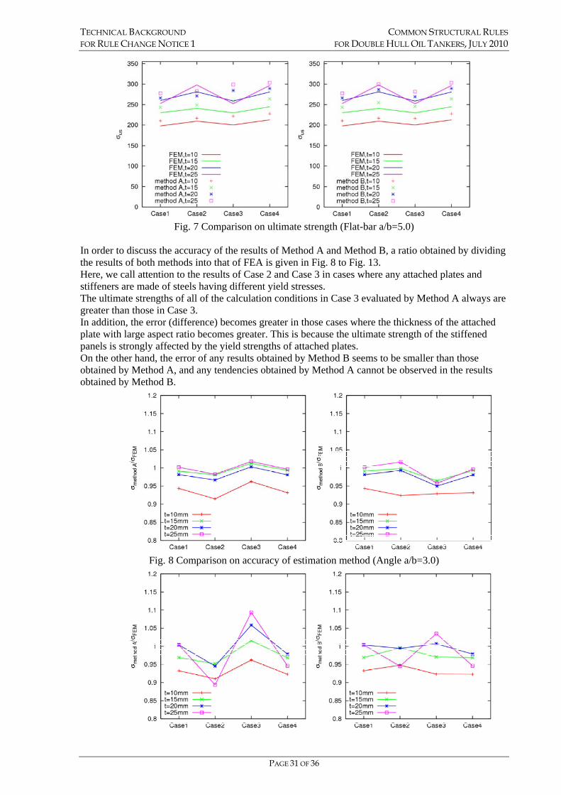
TECHNICAL BACKGROUND COMMON STRUCTURAL RULES FOR RULE CHANGE NOTICE 1 FOR DOUBLE HULL OIL TANKERS, JULY 2010
PAGE 31 OF 36
Fig. 7 Comparison on ultimate strength (Flat-bar a/b=5.0)
In order to discuss the accuracy of the results of Method A and Method B, a ratio obtained by dividing the results of both methods into that of FEA is given in Fig. 8 to Fig. 13. Here, we call attention to the results of Case 2 and Case 3 in cases where any attached plates and stiffeners are made of steels having different yield stresses. The ultimate strengths of all of the calculation conditions in Case 3 evaluated by Method A always are greater than those in Case 3. In addition, the error (difference) becomes greater in those cases where the thickness of the attached plate with large aspect ratio becomes greater. This is because the ultimate strength of the stiffened panels is strongly affected by the yield strengths of attached plates. On the other hand, the error of any results obtained by Method B seems to be smaller than those obtained by Method A, and any tendencies obtained by Method A cannot be observed in the results obtained by Method B.
Fig. 8 Comparison on accuracy of estimation method (Angle a/b=3.0)

TECHNICAL BACKGROUND COMMON STRUCTURAL RULES FOR RULE CHANGE NOTICE 1 FOR DOUBLE HULL OIL TANKERS, JULY 2010
PAGE 32 OF 36
Fig. 9 Comparison on accuracy of estimation method (Angle a/b=5.0)
Fig. 10 Comparison on accuracy of estimation method (T-bar a/b=4.0)
Fig. 11 Comparison on accuracy of estimation method (T-bar a/b=6.0)
Fig. 12 Comparison on accuracy of estimation method (Flat-bar a/b=3.0)

TECHNICAL BACKGROUND COMMON STRUCTURAL RULES FOR RULE CHANGE NOTICE 1 FOR DOUBLE HULL OIL TANKERS, JULY 2010
PAGE 33 OF 36
Fig. 13 Comparison on accuracy of estimation method (Flat-bar a/b=5.0)
For the purpose of confirming the accuracy of any results obtained by Method A and Method B, average values and coefficients of variation (COV) are calculated and those results are given in Figure 14 and 15.
Fig. 14 Averages of Ultimate Strength in Each Case Fig. 15 Coefficients of Variation in Each Case
From Figure 15, it is obvious that the variance of any results obtained by method B is small. This means the accuracy of any results obtained by Method B is higher than those results obtained by Method A. 4. Conclusion Two methods to estimate the ultimate strength of stiffened panels in cases where attached plates and stiffeners are made of steel having different yield stresses are considered. One is Method A, where the yield stress used in the estimation of beam-column buckling is calculated so as to be the weighted average value of the yield stresses of the stiffener and the attached plating according to their area. The other is method B, where the yield stress in the estimation of beam-column buckling is set to the weighted average value of the yield stresses of the stiffener and the attached plating according to the product of their areas and their distances from the neutral axis. In order to evaluate the accuracy of the ultimate strength of the stiffened panel obtained by both methods, the results obtained by both methods are compared to those obtained by 3D non-linear FEAs.
From these comparison works, the following findings are obtained.
(1) The method A is very simple and practicable, but it may overestimated the ultimate strength in the case that the yield strength of the stiffener is lower than that of the attach plating

TECHNICAL BACKGROUND COMMON STRUCTURAL RULES FOR RULE CHANGE NOTICE 1 FOR DOUBLE HULL OIL TANKERS, JULY 2010
PAGE 34 OF 36
(2) Method B is not as simple and practicable as Method A, but it gives more accurate ultimate strength values for stiffened panels in comparison to those obtained by Method A.
Therefore, in cases where attached panels and stiffeners are made of steel having different yield stresses, Method B should be used for the evaluation of the load end shortening curve thereof.
The text in the Rule Change Proposal is based on this.

TECHNICAL BACKGROUND COMMON STRUCTURAL RULES FOR RULE CHANGE NOTICE 1 FOR DOUBLE HULL OIL TANKERS, JULY 2010
PAGE 35 OF 36
APPENDIX B – STRUCTURAL STRENGTH ASSESSMENT Appendix B/2.4.7.7 & 2.4.7.9
1. Background
See background for Section 7/Table 7.6.1
Appendix B/2.5.1.2, 2.5.2.1 & 2.5.3.2
1. Background
See background for Section 9/2.4.5

TECHNICAL BACKGROUND COMMON STRUCTURAL RULES FOR RULE CHANGE NOTICE 1 FOR DOUBLE HULL OIL TANKERS, JULY 2010
PAGE 36 OF 36
APPENDIX C – FATIGUE STRENGTH ASSESSMENT Appendix C/1.4.4.20
1. Background
The proposed amendment is to correct the cross reference.
0000