ruc controlador
TRANSCRIPT

7/26/2019 RUC Controlador
http://slidepdf.com/reader/full/ruc-controlador 1/421
© ROBOTIQ INC. 2014
Get the latest version of the manual at support.robotiq.com

7/26/2019 RUC Controlador
http://slidepdf.com/reader/full/ruc-controlador 2/42
Table of Contents
Robotiq inc. © 2008 - 2014 2
Revisions . . . . . . . . . . . . . . . . . . . . . . . . . . . . . . . . . . . . . . . . . . . . . . . . . . . . . . . . . . . . . . . . . . . . . . . . . . . . . . . . . . . . . . . . . . . . . . . . . . . . 3 1. General Presentation . . . . . . . . . . . . . . . . . . . . . . . . . . . . . . . . . . . . . . . . . . . . . . . . . . . . . . . . . . . . . . . . . . . . . . . . . . . . . . . . . . . . . . . . . 4
2. Safety . . . . . . . . . . . . . . . . . . . . . . . . . . . . . . . . . . . . . . . . . . . . . . . . . . . . . . . . . . . . . . . . . . . . . . . . . . . . . . . . . . . . . . . . . . . . . . . . . . . . . 6 2.1 Warning . . . . . . . . . . . . . . . . . . . . . . . . . . . . . . . . . . . . . . . . . . . . . . . . . . . . . . . . . . . . . . . . . . . . . . . . . . . . . . . . . . . . . . . . . . . . . . . 7
2.2 Intended use . . . . . . . . . . . . . . . . . . . . . . . . . . . . . . . . . . . . . . . . . . . . . . . . . . . . . . . . . . . . . . . . . . . . . . . . . . . . . . . . . . . . . . . . . . . 8 3. Installation . . . . . . . . . . . . . . . . . . . . . . . . . . . . . . . . . . . . . . . . . . . . . . . . . . . . . . . . . . . . . . . . . . . . . . . . . . . . . . . . . . . . . . . . . . . . . . . . . 9
3.1 Scope of delivery . . . . . . . . . . . . . . . . . . . . . . . . . . . . . . . . . . . . . . . . . . . . . . . . . . . . . . . . . . . . . . . . . . . . . . . . . . . . . . . . . . . . . . . . 9 3.2 Environmental and operating conditions . . . . . . . . . . . . . . . . . . . . . . . . . . . . . . . . . . . . . . . . . . . . . . . . . . . . . . . . . . . . . . . . . . . . . . 10
3.3 Mechanical connections . . . . . . . . . . . . . . . . . . . . . . . . . . . . . . . . . . . . . . . . . . . . . . . . . . . . . . . . . . . . . . . . . . . . . . . . . . . . . . . . . . 11 3.4 Power supply specifications . . . . . . . . . . . . . . . . . . . . . . . . . . . . . . . . . . . . . . . . . . . . . . . . . . . . . . . . . . . . . . . . . . . . . . . . . . . . . . . 12
3.5 Wiring . . . . . . . . . . . . . . . . . . . . . . . . . . . . . . . . . . . . . . . . . . . . . . . . . . . . . . . . . . . . . . . . . . . . . . . . . . . . . . . . . . . . . . . . . . . . . . . . 13 3.5.1 Power connection . . . . . . . . . . . . . . . . . . . . . . . . . . . . . . . . . . . . . . . . . . . . . . . . . . . . . . . . . . . . . . . . . . . . . . . . . . . . . . . . . . 15 3.5.2 Communication connection . . . . . . . . . . . . . . . . . . . . . . . . . . . . . . . . . . . . . . . . . . . . . . . . . . . . . . . . . . . . . . . . . . . . . . . . . . . 17
Real-time Ethernet communication protocols . . . . . . . . . . . . . . . . . . . . . . . . . . . . . . . . . . . . . . . . . . . . . . . . . . . . . . . . . . . . . . 19 DeviceNet communication protocol . . . . . . . . . . . . . . . . . . . . . . . . . . . . . . . . . . . . . . . . . . . . . . . . . . . . . . . . . . . . . . . . . . . . . . 22 CANopen communication protocol . . . . . . . . . . . . . . . . . . . . . . . . . . . . . . . . . . . . . . . . . . . . . . . . . . . . . . . . . . . . . . . . . . . . . . 24
PROFIBUS communication protocol . . . . . . . . . . . . . . . . . . . . . . . . . . . . . . . . . . . . . . . . . . . . . . . . . . . . . . . . . . . . . . . . . . . . . 26 4. Control . . . . . . . . . . . . . . . . . . . . . . . . . . . . . . . . . . . . . . . . . . . . . . . . . . . . . . . . . . . . . . . . . . . . . . . . . . . . . . . . . . . . . . . . . . . . . . . . . . . . 27
4.1 Overview . . . . . . . . . . . . . . . . . . . . . . . . . . . . . . . . . . . . . . . . . . . . . . . . . . . . . . . . . . . . . . . . . . . . . . . . . . . . . . . . . . . . . . . . . . . . . . 27 4.2 Status LEDs . . . . . . . . . . . . . . . . . . . . . . . . . . . . . . . . . . . . . . . . . . . . . . . . . . . . . . . . . . . . . . . . . . . . . . . . . . . . . . . . . . . . . . . . . . . 28
4.2.1 Supply LED . . . . . . . . . . . . . . . . . . . . . . . . . . . . . . . . . . . . . . . . . . . . . . . . . . . . . . . . . . . . . . . . . . . . . . . . . . . . . . . . . . . . . . . 29 4.2.2 Communication LED . . . . . . . . . . . . . . . . . . . . . . . . . . . . . . . . . . . . . . . . . . . . . . . . . . . . . . . . . . . . . . . . . . . . . . . . . . . . . . . . 29
4.2.3 Fault LED . . . . . . . . . . . . . . . . . . . . . . . . . . . . . . . . . . . . . . . . . . . . . . . . . . . . . . . . . . . . . . . . . . . . . . . . . . . . . . . . . . . . . . . . . 30 4.3 Controller register mapping . . . . . . . . . . . . . . . . . . . . . . . . . . . . . . . . . . . . . . . . . . . . . . . . . . . . . . . . . . . . . . . . . . . . . . . . . . . . . . . . 31
4.4 Robot output registers & functionalities . . . . . . . . . . . . . . . . . . . . . . . . . . . . . . . . . . . . . . . . . . . . . . . . . . . . . . . . . . . . . . . . . . . . . . . 31 4.5 Robot input registers & status . . . . . . . . . . . . . . . . . . . . . . . . . . . . . . . . . . . . . . . . . . . . . . . . . . . . . . . . . . . . . . . . . . . . . . . . . . . . . . 32
5. User Interface . . . . . . . . . . . . . . . . . . . . . . . . . . . . . . . . . . . . . . . . . . . . . . . . . . . . . . . . . . . . . . . . . . . . . . . . . . . . . . . . . . . . . . . . . . . . . . 33 6. Specifications . . . . . . . . . . . . . . . . . . . . . . . . . . . . . . . . . . . . . . . . . . . . . . . . . . . . . . . . . . . . . . . . . . . . . . . . . . . . . . . . . . . . . . . . . . . . . . . 33 6.1 Technical dimensions . . . . . . . . . . . . . . . . . . . . . . . . . . . . . . . . . . . . . . . . . . . . . . . . . . . . . . . . . . . . . . . . . . . . . . . . . . . . . . . . . . . . 34
6.2 Mechanical specifications . . . . . . . . . . . . . . . . . . . . . . . . . . . . . . . . . . . . . . . . . . . . . . . . . . . . . . . . . . . . . . . . . . . . . . . . . . . . . . . . . 35 6.3 Moment of inertia and center of mass . . . . . . . . . . . . . . . . . . . . . . . . . . . . . . . . . . . . . . . . . . . . . . . . . . . . . . . . . . . . . . . . . . . . . . . . 35
6.4 Electrical ratings . . . . . . . . . . . . . . . . . . . . . . . . . . . . . . . . . . . . . . . . . . . . . . . . . . . . . . . . . . . . . . . . . . . . . . . . . . . . . . . . . . . . . . . . 36 7. Maintenance . . . . . . . . . . . . . . . . . . . . . . . . . . . . . . . . . . . . . . . . . . . . . . . . . . . . . . . . . . . . . . . . . . . . . . . . . . . . . . . . . . . . . . . . . . . . . . . 37
8. Spare Parts, Kits and Accessories . . . . . . . . . . . . . . . . . . . . . . . . . . . . . . . . . . . . . . . . . . . . . . . . . . . . . . . . . . . . . . . . . . . . . . . . . . . . . . . 37 9. Troubleshooting . . . . . . . . . . . . . . . . . . . . . . . . . . . . . . . . . . . . . . . . . . . . . . . . . . . . . . . . . . . . . . . . . . . . . . . . . . . . . . . . . . . . . . . . . . . . . 38
10. Warranty . . . . . . . . . . . . . . . . . . . . . . . . . . . . . . . . . . . . . . . . . . . . . . . . . . . . . . . . . . . . . . . . . . . . . . . . . . . . . . . . . . . . . . . . . . . . . . . . . 40 11. Contact . . . . . . . . . . . . . . . . . . . . . . . . . . . . . . . . . . . . . . . . . . . . . . . . . . . . . . . . . . . . . . . . . . . . . . . . . . . . . . . . . . . . . . . . . . . . . . . . . . . 41
7/26/2019 RUC Controlador
http://slidepdf.com/reader/full/ruc-controlador 3/42
Robotiq Universal Controller Instruction Manual
Robotiq inc. © 2008 - 2014 3
Revisions
Robotiq may modify this product without notice, when necessary, due to product improvements, modifications or
changes in specifications. If such modification is made, the manual will also be revised, see revision information.
See the latest version of this manual online at .http://support.robotiq.com/
Revision 140626
Manual release
Copyright
© 2008-2014 Robotiq Inc. All rights reserved.
This manual, and the product it describes, are protected by the Copyright Act of Canada, by laws of other countries,
and by international treaties, and therefore may not be reproduced in whole or in part, whether for sale or not,
without prior written consent from Robotiq. Under copyright law, copying includes translation into another language
or format.
Information provided by Robotiq in this document is believed to be accurate and reliable. However, no responsibility
is assumed by Robotiq for its use. There may be some differences between the manual and the product if the
product has been modified after the edition date.
The information contained in this document is subject to change without notice.
7/26/2019 RUC Controlador
http://slidepdf.com/reader/full/ruc-controlador 4/42
Robotiq Universal Controller Instruction Manual
Robotiq inc. © 2008 - 2014 4
1. General Presentation
The terms "Controller", "Universal Controller", "Robotiq Controller" , "K-Model", and "Robotiq Universal Controller"
used in the following manual all refer to the . The Robotiq Universal Controller is aRobotiq Universal Controller
robotic peripheral controller for other Robotiq devices and communication with other robot controllers. The Universal
Controller is designed for industrial applications with various communication protocols and is common to all Robotiq
devices.
Note
The following manual uses the metric system, unless specified, all dimensions are in
.millimeters
Note
The following section presents the key features of the Controller and must not be considered as
related to Controller operation, each feature is detailed in an appropriate section of the manual.
Safety guidelines must be read and understood before any operation is attempted with the
Controller.
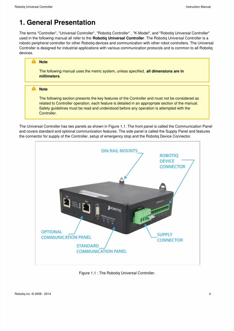
The Universal Controller has two panels as shown in Figure 1.1. The front panel is called the Communication Panel
and covers standard and optional communication features. The side panel is called the Supply Panel and features
the connector for supply of the Controller, setup of emergency stop and the Robotiq Device Connector.
Figure 1.1 : The Robotiq Universal Controller.
7/26/2019 RUC Controlador
http://slidepdf.com/reader/full/ruc-controlador 5/42
Robotiq Universal Controller Instruction Manual
Robotiq inc. © 2008 - 2014 5
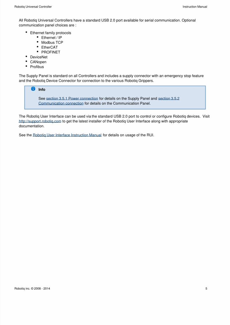
All Robotiq Universal Controllers have a standard USB 2.0 port available for serial communication. Optional
communication panel choices are :
Ethernet family protocols
Ethernet / IP
Modbus TCP
EtherCAT
PROFINET
DeviceNetCANopen
Profibus
The Supply Panel is standard on all Controllers and includes a supply connector with an emergency stop feature
and the Robotiq Device Connector for connection to the various Robotiq Grippers.
Info
See for details on the Supply Panel andsection 3.5.1 Power connection section 3.5.2
for details on the Communication Panel.Communication connection
The Robotiq User Interface can be used via the standard USB 2.0 port to control or configure Robotiq devices. Visit
http://support.robotiq.com to get the latest installer of the Robotiq User Interface along with appropriate
documentation.
See the for details on usage of the RUI.Robotiq User Interface Instruction Manual
7/26/2019 RUC Controlador
http://slidepdf.com/reader/full/ruc-controlador 6/42
Robotiq Universal Controller Instruction Manual
Robotiq inc. © 2008 - 2014 6
2. Safety
Warning
The operator must have read and understood all of the instructions in the following
manual before handling the Robotiq Universal Controller and the associated Gripper
device.
The term "operator" refers to anyone responsible for any of the following operations on the
Universal Controller and associated Gripper device :
Installation
Control
Maintenance
Inspection
Calibration
Programming
Decommissioning
This documentation explains the various components of the Universal Controller and its general operation. Read this
documentation and the associated Robotiq Gripper device documentation and be sure to understand its contents
before handling the Controller or Gripper.
The drawings and photos in this documentation are representative examples and differences may exist between
them and the delivered product.
7/26/2019 RUC Controlador
http://slidepdf.com/reader/full/ruc-controlador 7/42
Robotiq Universal Controller Instruction Manual
Robotiq inc. © 2008 - 2014 7
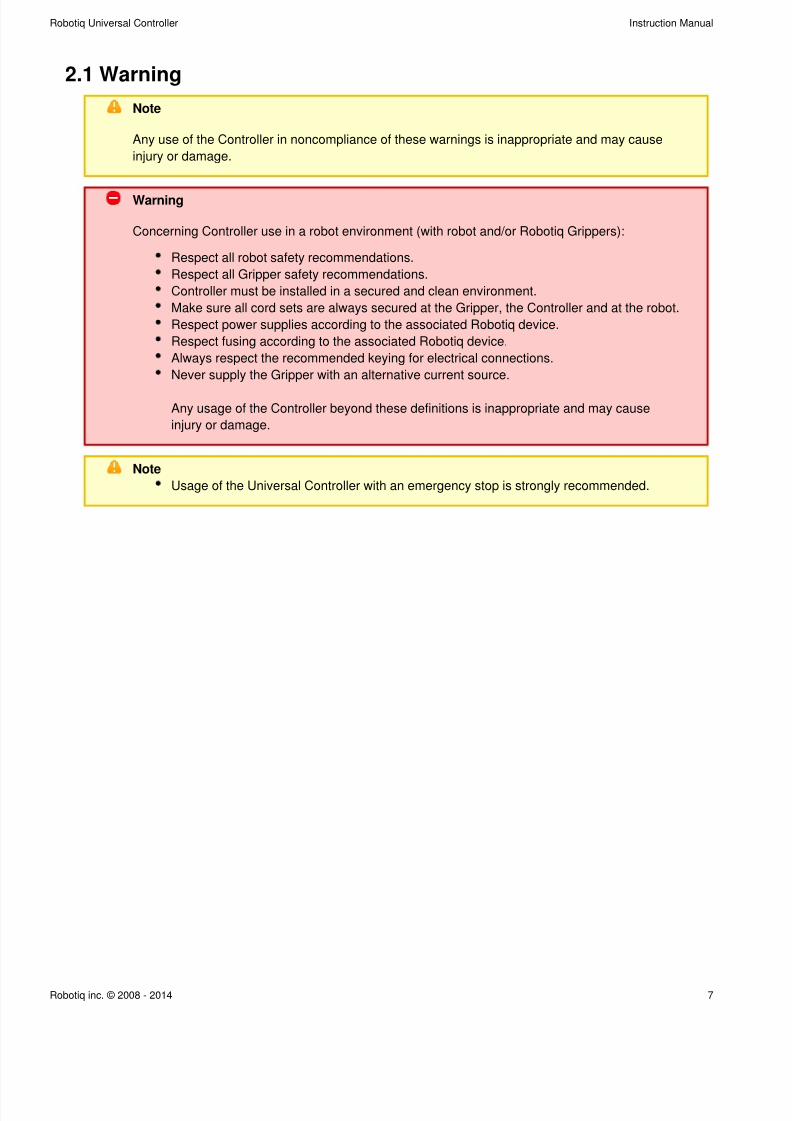
2.1 Warning
Note
Any use of the Controller in noncompliance of these warnings is inappropriate and may cause
injury or damage.
Warning
Concerning Controller use in a robot environment (with robot and/or Robotiq Grippers):
Respect all robot safety recommendations.
Respect all Gripper safety recommendations.
Controller must be installed in a secured and clean environment.
Make sure all cord sets are always secured at the Gripper, the Controller and at the robot.
Respect power supplies according to the associated Robotiq device.
Respect fusing according to the associated Robotiq device.
Always respect the recommended keying for electrical connections.
Never supply the Gripper with an alternative current source.
Any usage of the Controller beyond these definitions is inappropriate and may cause
injury or damage.
Note
Usage of the Universal Controller with an emergency stop is strongly recommended.
7/26/2019 RUC Controlador
http://slidepdf.com/reader/full/ruc-controlador 8/42
Robotiq Universal Controller Instruction Manual
Robotiq inc. © 2008 - 2014 8
2.2 Intended use
The Controller unit is designed for control of Robotiq devices such as the Robotiq Adaptive Robot Gripper series.
Caution
The Controller is NOT intended for robot control.
The product is intended to be installed in parallel to a robot or other automated machinery or equipment.
Note
Always comply with local and/or national laws, regulations and directives on automation safety
and general machine safety.
The unit may be used only within the range of its technical data. Any other use of the product is deemed improper
and unintended use. Robotiq will not be liable for any damages resulting from improper use.
7/26/2019 RUC Controlador
http://slidepdf.com/reader/full/ruc-controlador 9/42
Robotiq Universal Controller Instruction Manual
Robotiq inc. © 2008 - 2014 9
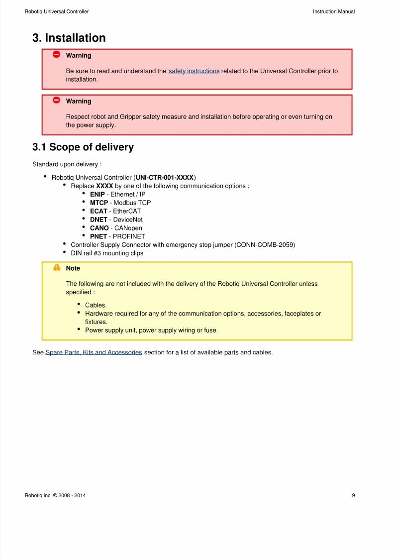
3. Installation
Warning
Be sure to read and understand the related to the Universal Controller prior tosafety instructions
installation.
Warning
Respect robot and Gripper safety measure and installation before operating or even turning on
the power supply.
3.1 Scope of delivery
Standard upon delivery :
Robotiq Universal Controller ( )UNI-CTR-001-XXXX
Replace by one of the following communication options :XXXX
ENIP - Ethernet / IPMTCP - Modbus TCP
ECAT - EtherCAT
DNET - DeviceNet
CANO - CANopen
PNET - PROFINET
Controller Supply Connector with emergency stop jumper (CONN-COMB-2059)
DIN rail #3 mounting clips
Note
The following are not included with the delivery of the Robotiq Universal Controller unless
:specified
Cables.
Hardware required for any of the communication options, accessories, faceplates or
fixtures.
Power supply unit, power supply wiring or fuse.
See section for a list of available parts and cables.Spare Parts, Kits and Accessories
7/26/2019 RUC Controlador
http://slidepdf.com/reader/full/ruc-controlador 10/42
Robotiq Universal Controller Instruction Manual
Robotiq inc. © 2008 - 2014 10
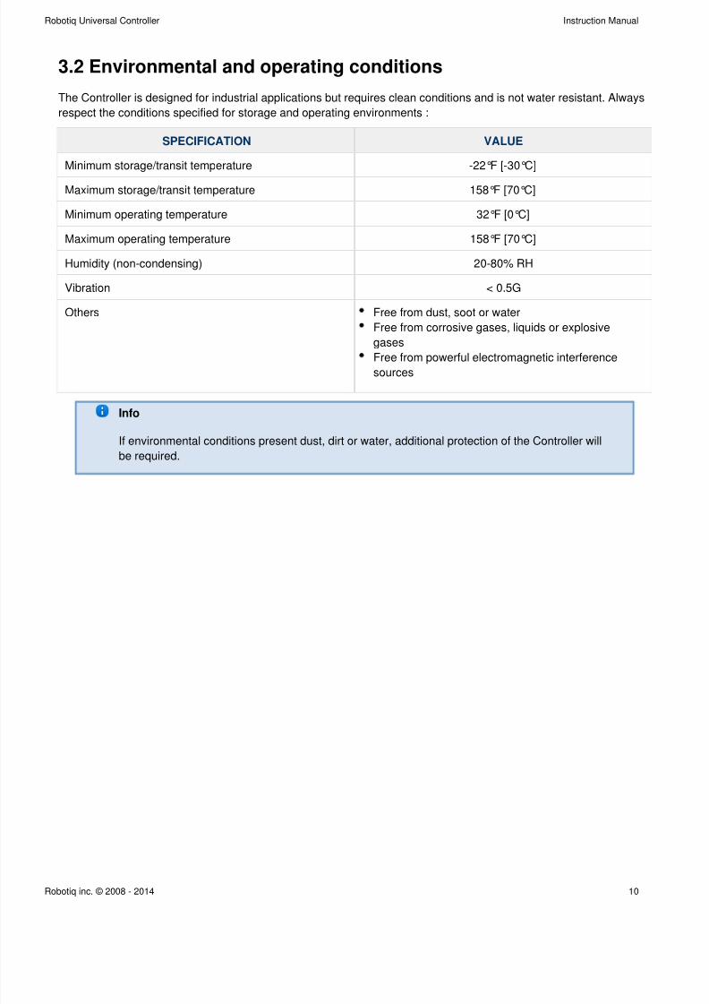
3.2 Environmental and operating conditions
The Controller is designed for industrial applications but requires clean conditions and is not water resistant. Always
respect the conditions specified for storage and operating environments :
SPECIFICATION VALUE
Minimum storage/transit temperature -22°F [-30°C]
Maximum storage/transit temperature 158°F [70°C]
Minimum operating temperature 32°F [0°C]
Maximum operating temperature 158°F [70°C]
Humidity (non-condensing) 20-80% RH
Vibration < 0.5G
Others Free from dust, soot or water
Free from corrosive gases, liquids or explosive
gases
Free from powerful electromagnetic interference
sources
Info
If environmental conditions present dust, dirt or water, additional protection of the Controller will
be required.
7/26/2019 RUC Controlador
http://slidepdf.com/reader/full/ruc-controlador 11/42
Robotiq Universal Controller Instruction Manual
Robotiq inc. © 2008 - 2014 11
1.
2.
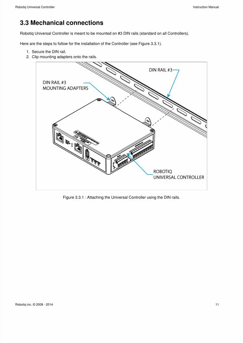
3.3 Mechanical connections
Robotiq Universal Controller is meant to be mounted on #3 DIN rails (standard on all Controllers).
Here are the steps to follow for the installation of the Controller (see Figure 3.3.1).
Secure the DIN rail.
Clip mounting adapters onto the rails.
Figure 3.3.1 : Attaching the Universal Controller using the DIN rails.
7/26/2019 RUC Controlador
http://slidepdf.com/reader/full/ruc-controlador 12/42
Robotiq Universal Controller Instruction Manual
Robotiq inc. © 2008 - 2014 12
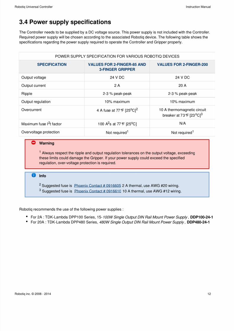
3.4 Power supply specifications
The Controller needs to be supplied by a DC voltage source. This power supply is not included with the Controller.
Required power supply will be chosen according to the associated Robotiq device. The following table shows the
specifications regarding the power supply required to operate the Controller and Gripper properly.
POWER SUPPLY SPECIFICATION FOR VARIOUS ROBOTIQ DEVICES
SPECIFICATION VALUES FOR 2-FINGER-85 AND
3-FINGER GRIPPER
VALUES FOR 2-FINGER-200
Output voltage 24 V DC 24 V DC
Output current 2 A 20 A
Ripple 2-3 % peak-peak 2-3 % peak-peak
Output regulation 10% maximum 10% maximum
Overcurrent 4 A fuse at 77°F [25 C]o 2 10 A thermomagnetic circuit
breaker at 73°F [23oC]
3
Maximum fuse I t factor2 100 A s at 77°F [25 C]2 o N/A
Overvoltage protection Not required1 Not required1
Warning
1 Always respect the ripple and output regulation tolerances on the output voltage, exceeding
these limits could damage the Gripper. If your power supply could exceed the specified
regulation, over-voltage protection is required.
Info
2 Suggested fuse is 2 A thermal, use AWG #20 wiring.Phoenix Contact # 0916605
3 Suggested fuse is Phoenix Contact # 0916610 10 A thermal, use AWG #12 wiring.
Robotiq recommends the use of the following power supplies :
For 2A : TDK-Lambda DPP100 Series, 15- ,100W Single Output DIN Rail Mount Power Supply DDP100-24-1
For 20A : TDK-Lambda DPP480 Series, ,480W Single Output DIN Rail Mount Power Supply DDP480-24-1
7/26/2019 RUC Controlador
http://slidepdf.com/reader/full/ruc-controlador 13/42
Robotiq Universal Controller Instruction Manual
Robotiq inc. © 2008 - 2014 13
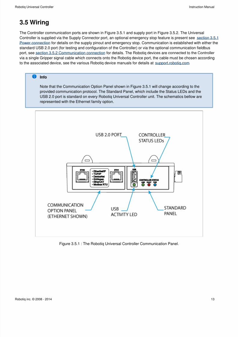
3.5 Wiring
The Controller communication ports are shown in Figure 3.5.1 and supply port in Figure 3.5.2. The Universal
Controller is supplied via the Supply Connector port, an optional emergency stop feature is present see section 3.5.1
for details on the supply pinout and emergency stop. Communication is established with either thePower connection
standard USB 2.0 port (for testing and configuration of the Controller) or via the optional communication fieldbus
port, see for details. The Robotiq devices are connected to the Controllersection 3.5.2 Communication connection
via a single Gripper signal cable which connects onto the Robotiq device port, the cable must be chosen accordingto the associated device, see the various Robotiq device manuals for details at .support.robotiq.com
Info
Note that the Communication Option Panel shown in Figure 3.5.1 will change according to the
provided communication protocol. The Standard Panel, which include the Status LEDs and the
USB 2.0 port is standard on every Robotiq Universal Controller unit. The schematics bellow are
represented with the Ethernet family option.
Figure 3.5.1 : The Robotiq Universal Controller Communication Panel.
7/26/2019 RUC Controlador
http://slidepdf.com/reader/full/ruc-controlador 14/42
Robotiq Universal Controller Instruction Manual
Robotiq inc. © 2008 - 2014 14
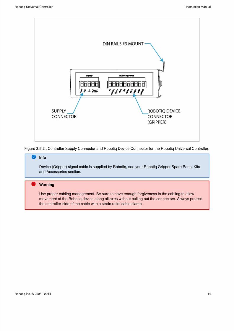
Figure 3.5.2 : Controller Supply Connector and Robotiq Device Connector for the Robotiq Universal Controller.
Info
Device (Gripper) signal cable is supplied by Robotiq, see your Robotiq Gripper Spare Parts, Kits
and Accessories section.
Warning
Use proper cabling management. Be sure to have enough forgiveness in the cabling to allow
movement of the Robotiq device along all axes without pulling out the connectors. Always protect
the controller-side of the cable with a strain relief cable clamp.
7/26/2019 RUC Controlador
http://slidepdf.com/reader/full/ruc-controlador 15/42
Robotiq Universal Controller Instruction Manual
Robotiq inc. © 2008 - 2014 15
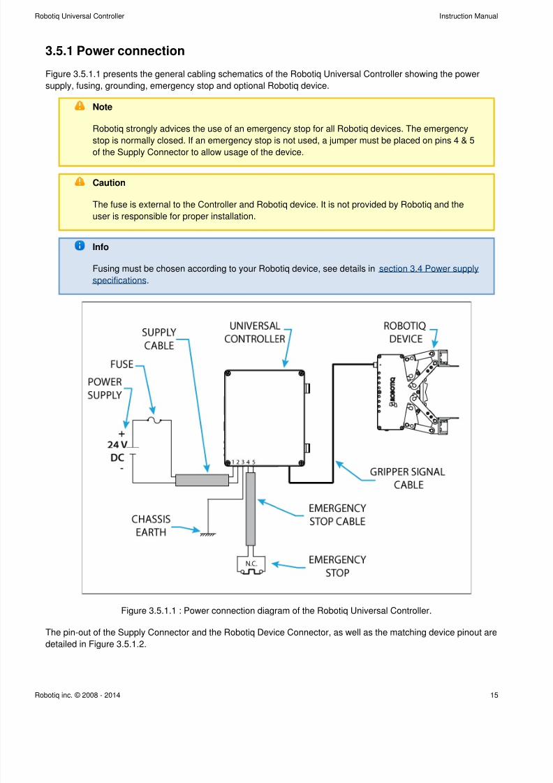
3.5.1 Power connection
Figure 3.5.1.1 presents the general cabling schematics of the Robotiq Universal Controller showing the power
supply, fusing, grounding, emergency stop and optional Robotiq device.
Note
Robotiq strongly advices the use of an emergency stop for all Robotiq devices. The emergency
stop is normally closed. If an emergency stop is not used, a jumper must be placed on pins 4 & 5
of the Supply Connector to allow usage of the device.
Caution
The fuse is external to the Controller and Robotiq device. It is not provided by Robotiq and the
user is responsible for proper installation.
Info
Fusing must be chosen according to your Robotiq device, see details in section 3.4 Power supply
.specifications
Figure 3.5.1.1 : Power connection diagram of the Robotiq Universal Controller.
The pin-out of the Supply Connector and the Robotiq Device Connector, as well as the matching device pinout are
detailed in Figure 3.5.1.2.
7/26/2019 RUC Controlador
http://slidepdf.com/reader/full/ruc-controlador 16/42
Robotiq Universal Controller Instruction Manual
Robotiq inc. © 2008 - 2014 16
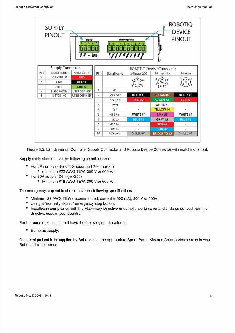
Figure 3.5.1.2 : Universal Controller Supply Connector and Robotiq Device Connector with matching pinout.
Supply cable should have the following specifications :
For 2A supply (3-Finger Gripper and 2-Finger-85)
minimum #22 AWG TEW, 300 V or 600 V.
For 20A supply (2-Finger-200)
Minimum #16 AWG TEW, 300 V or 600 V.
The emergency stop cable should have the following specifications :
Minimum 22 AWG TEW (recommended, current is 500 mA), 300 V or 600V.
Using a "normally closed" emergency stop button.
Installed in compliance with the Machinery Directive or compliance to national standards derived from the
directive used in your country.
Earth grounding cable should have the following specifications :
Same as supply.
Gripper signal cable is supplied by Robotiq, see the appropriate Spare Parts, Kits and Accessories section in your
Robotiq device manual.
7/26/2019 RUC Controlador
http://slidepdf.com/reader/full/ruc-controlador 17/42
Robotiq Universal Controller Instruction Manual
Robotiq inc. © 2008 - 2014 17
3.5.2 Communication connection
The following table summarizes the communication protocols available for the Controller. A USB connection is
standard on all Controllers, while the optional communication panel will be setup for your options with a single
communication protocol. See the following subsection for details on the communication parameters of each
communication option.
Note
Only one protocol option is available for a given Controller unit.
Family Protocol
Real-Time Ethernet Ethernet / IP
Modbus TCP/IP
EtherCAT
ProfiNET
Fieldbus DeviceNET
CANopen
ProfiBUS
USB Modbus RTU
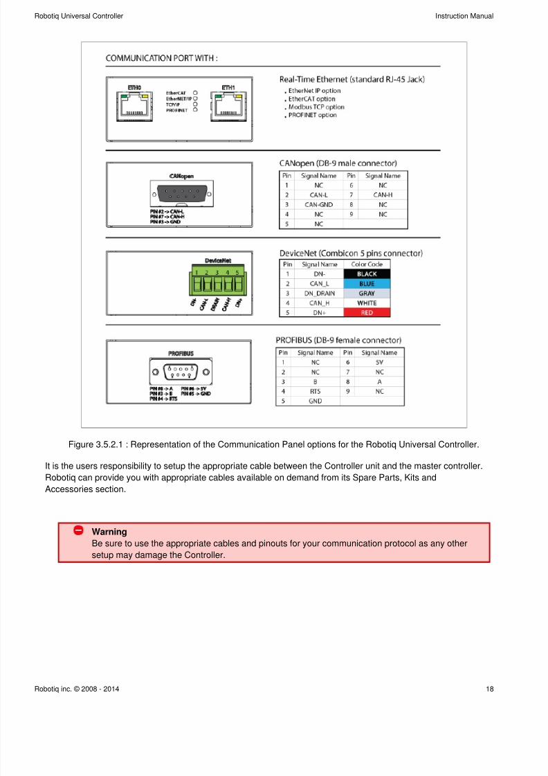
The Figure 3.5.2.1 shows the Communication Panel of the Robotiq Universal Controller. The communication port
will vary depending on the communication protocol chosen. Real-Time Ethernet family protocols ( Ethernet IP,
EtherCAT, Modbus TCP) will come with two (2) RJ45 standard ports. DeviceNet protocol will come with a 5-pin
Combicon connector, CANopen with a standard male DB-9 connector, finally ProfiBUS will come with a standardfemale DB-9 connector.
7/26/2019 RUC Controlador
http://slidepdf.com/reader/full/ruc-controlador 18/42
Robotiq Universal Controller Instruction Manual
Robotiq inc. © 2008 - 2014 18
Figure 3.5.2.1 : Representation of the Communication Panel options for the Robotiq Universal Controller.
It is the users responsibility to setup the appropriate cable between the Controller unit and the master controller.
Robotiq can provide you with appropriate cables available on demand from its Spare Parts, Kits and
Accessories section.
Warning
Be sure to use the appropriate cables and pinouts for your communication protocol as any othersetup may damage the Controller.
7/26/2019 RUC Controlador
http://slidepdf.com/reader/full/ruc-controlador 19/42
Robotiq Universal Controller Instruction Manual
Robotiq inc. © 2008 - 2014 19
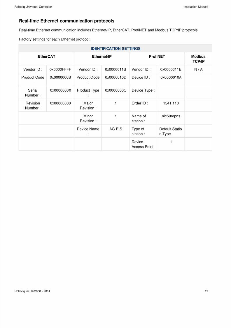
Real-time Ethernet communication protocols
Real-time Ethernet communication includes Ethernet/IP, EtherCAT, ProfiNET and Modbus TCP/IP protocols.
Factory settings for each Ethernet protocol:
IDENTIFICATION SETTINGS
EtherCAT Ethernet/IP ProfiNET ModbusTCP/IP
Vendor ID : 0x0000FFFF Vendor ID : 0x0000011B Vendor ID : 0x0000011E N / A
Product Code
:
0x0000000B Product Code
:
0x0000010D Device ID : 0x0000010A
Serial
Number :
0x00000000 Product Type
:
0x0000000C Device Type :
Revision
Number :
0x00000000 Major
Revision :
1 Order ID : 1541.110
MinorRevision :
1 Name ofstation :
nic50repns
Device Name
:
AG-EIS Type of
station :
Default.Statio
n.Type
Device
Access Point
1
7/26/2019 RUC Controlador
http://slidepdf.com/reader/full/ruc-controlador 20/42
Robotiq Universal Controller Instruction Manual
Robotiq inc. © 2008 - 2014 20
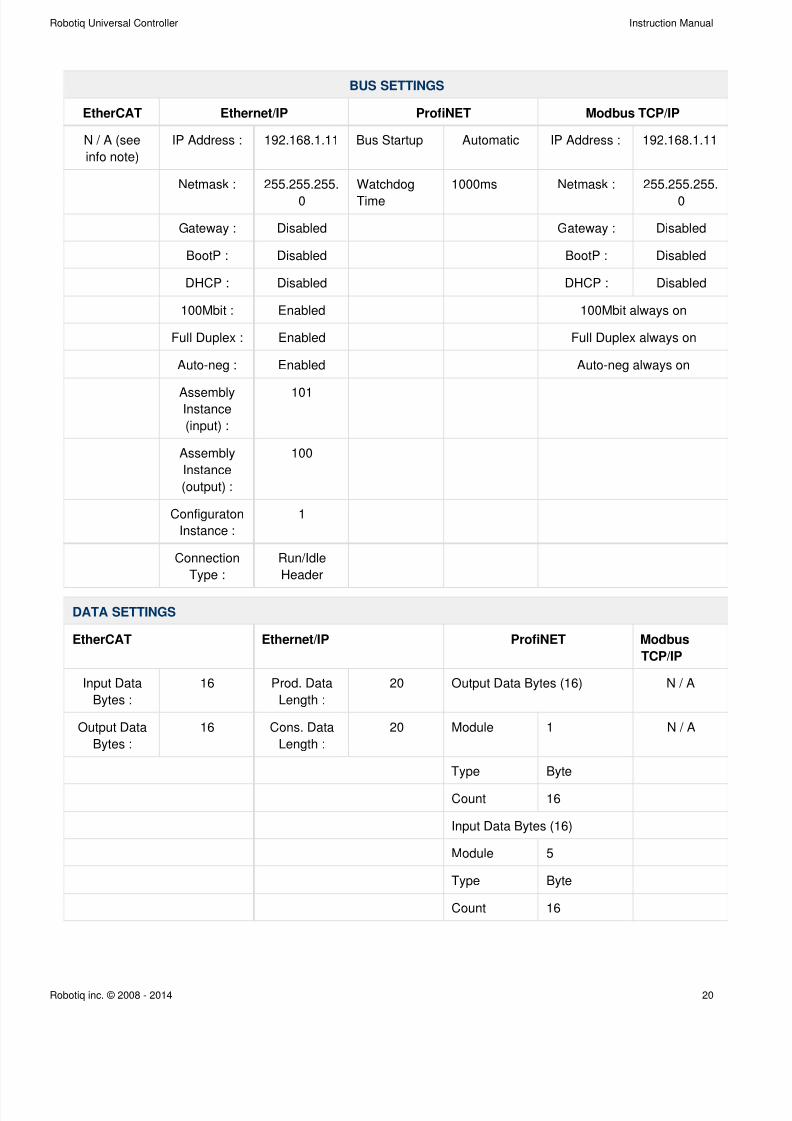
BUS SETTINGS
EtherCAT Ethernet/IP ProfiNET Modbus TCP/IP
N / A (see
info note)
IP Address : 192.168.1.11 Bus Startup Automatic IP Address : 192.168.1.11
Netmask : 255.255.255.
0
Watchdog
Time
1000ms Netmask : 255.255.255.
0
Gateway : Disabled Gateway : Disabled
BootP : Disabled BootP : Disabled
DHCP : Disabled DHCP : Disabled
100Mbit : Enabled 100Mbit always on
Full Duplex : Enabled Full Duplex always on
Auto-neg : Enabled Auto-neg always on
AssemblyInstance
(input) :
101
Assembly
Instance
(output) :
100
Configuraton
Instance :
1
Connection
Type :
Run/Idle
Header
DATA SETTINGS
EtherCAT Ethernet/IP ProfiNET Modbus
TCP/IP
Input Data
Bytes :
16 Prod. Data
Length :
20 Output Data Bytes (16) N / A
Output Data
Bytes :
16 Cons. Data
Length :
20 Module 1 N / A
Type Byte
Count 16
Input Data Bytes (16)
Module 5
Type Byte
Count 16
7/26/2019 RUC Controlador
http://slidepdf.com/reader/full/ruc-controlador 21/42
Robotiq Universal Controller Instruction Manual
Robotiq inc. © 2008 - 2014 21
Info
EtherCAT protocol uses inherent dynamic addressing, thus bus settings cannot be customized.
Info
Ethernet/IP uses 4 bytes of header which may be visible or not depending on the master.
7/26/2019 RUC Controlador
http://slidepdf.com/reader/full/ruc-controlador 22/42
Robotiq Universal Controller Instruction Manual
Robotiq inc. © 2008 - 2014 22
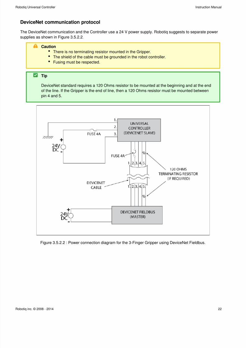
DeviceNet communication protocol
The DeviceNet communication and the Controller use a 24 V power supply. Robotiq suggests to separate power
supplies as shown in Figure 3.5.2.2.
Caution
There is no terminating resistor mounted in the Gripper.
The shield of the cable must be grounded in the robot controller.
Fusing must be respected.
Tip
DeviceNet standard requires a 120 Ohms resistor to be mounted at the beginning and at the end
of the line. If the Gripper is the end of line, then a 120 Ohms resistor must be mounted between
pin 4 and 5.
Figure 3.5.2.2 : Power connection diagram for the 3-Finger Gripper using DeviceNet Fieldbus.
7/26/2019 RUC Controlador
http://slidepdf.com/reader/full/ruc-controlador 23/42
Robotiq Universal Controller Instruction Manual
Robotiq inc. © 2008 - 2014 23
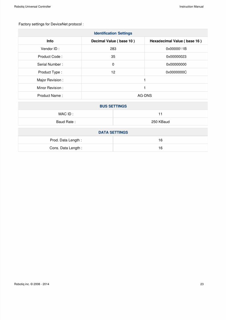
Factory settings for DeviceNet protocol :
Identification Settings
Info Decimal Value ( base 10 ) Hexadecimal Value ( base 16 )
Vendor ID : 283 0x0000011B
Product Code : 35 0x00000023
Serial Number : 0 0x00000000
Product Type : 12 0x0000000C
Major Revision : 1
Minor Revision : 1
Product Name : AG-DNS
BUS SETTINGS
MAC ID : 11
Baud Rate : 250 KBaud
DATA SETTINGS
Prod. Data Length : 16
Cons. Data Length : 16
7/26/2019 RUC Controlador
http://slidepdf.com/reader/full/ruc-controlador 24/42
Robotiq Universal Controller Instruction Manual
Robotiq inc. © 2008 - 2014 24
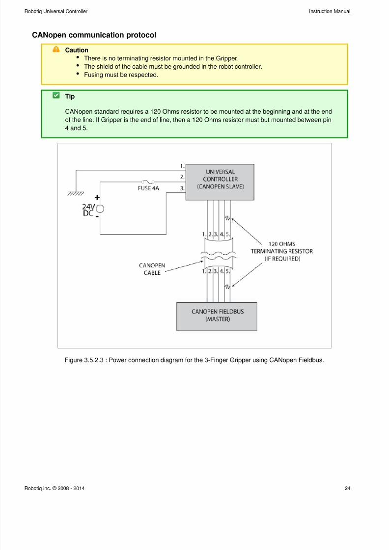
CANopen communication protocol
Caution
There is no terminating resistor mounted in the Gripper.
The shield of the cable must be grounded in the robot controller.
Fusing must be respected.
Tip
CANopen standard requires a 120 Ohms resistor to be mounted at the beginning and at the end
of the line. If Gripper is the end of line, then a 120 Ohms resistor must but mounted between pin
4 and 5.
Figure 3.5.2.3 : Power connection diagram for the 3-Finger Gripper using CANopen Fieldbus.
7/26/2019 RUC Controlador
http://slidepdf.com/reader/full/ruc-controlador 25/42
Robotiq Universal Controller Instruction Manual
Robotiq inc. © 2008 - 2014 25
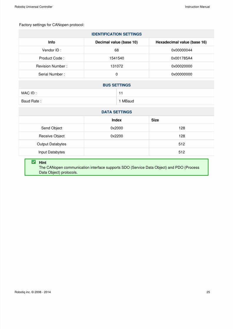
Factory settings for CANopen protocol:
IDENTIFICATION SETTINGS
Info Decimal value (base 10) Hexadecimal value (base 16)
Vendor ID : 68 0x00000044
Product Code : 1541540 0x001785A4
Revision Number : 131072 0x00020000
Serial Number : 0 0x00000000
BUS SETTINGS
MAC ID : 11
Baud Rate : 1 MBaud
DATA SETTINGS
Index Size
Send Object 0x2000 128
Receive Object 0x2200 128
Output Databytes 512
Input Databytes 512
Hint
The CANopen communication interface supports SDO (Service Data Object) and PDO (Process
Data Object) protocols.
7/26/2019 RUC Controlador
http://slidepdf.com/reader/full/ruc-controlador 26/42
Robotiq Universal Controller Instruction Manual
Robotiq inc. © 2008 - 2014 26
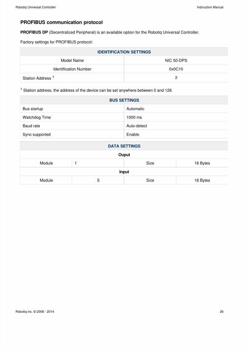
PROFIBUS communication protocol
PROFIBUS DP (Decentralized Peripheral) is an available option for the Robotiq Universal Controller.
Factory settings for PROFIBUS protocol:
IDENTIFICATION SETTINGS
Model Name NIC 50-DPS
Identification Number 0x0C10
Station Address 1 2
1 Station address, the address of the device can be set anywhere between 0 and 126.
BUS SETTINGS
Bus startup Automatic
Watchdog Time 1000 ms
Baud rate Auto-detect
Sync supported Enable
DATA SETTINGS
Ouput
Module 1 Size 16 Bytes
Input
Module 5 Size 16 Bytes
7/26/2019 RUC Controlador
http://slidepdf.com/reader/full/ruc-controlador 27/42
Robotiq Universal Controller Instruction Manual
Robotiq inc. © 2008 - 2014 27
4. Control
Info
Unless specified, all values in section 4 are hexadecimal values.
Info
Register format is Little Endian (Intel format), namely from LSB (Less Significant Bit) to MSB
(Most Significant Bit). Meaning that bytes are written with the least significant byte in the smallest
address. If Big-endian it would be writing from left to right, Little-endian would be writing from
right to left.
4.1 Overview
The Robotiq Universal Controller is accessed from the robot controller using an industrial protocol (Ethernet/IP,
DeviceNet, CANopen, EtherCAT, etc.) and used to operate a Robotiq device. The programming of the Robotiq
device can be done with the of the robot or by offline programming. To have more information onTeach Pendant
your Robotiq device controls see the appropriate section in your device manual at .support.robotiq.com
Info
When accessing the Universal Controller with no Robotiq devices, no command can be sent and
only fault status can be read. See the for details.input registers & status section
7/26/2019 RUC Controlador
http://slidepdf.com/reader/full/ruc-controlador 28/42
Robotiq Universal Controller Instruction Manual
Robotiq inc. © 2008 - 2014 28
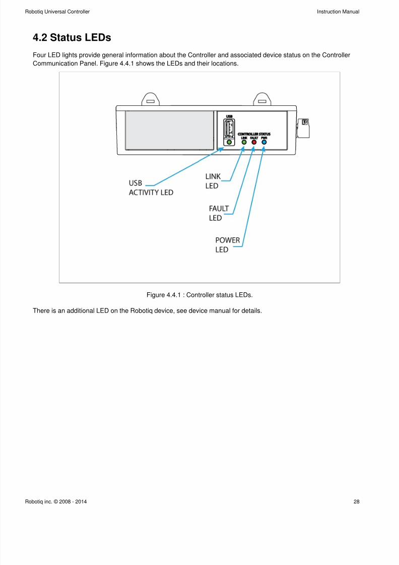
4.2 Status LEDs
Four LED lights provide general information about the Controller and associated device status on the Controller
Communication Panel. Figure 4.4.1 shows the LEDs and their locations.
Figure 4.4.1 : Controller status LEDs.
There is an additional LED on the Robotiq device, see device manual for details.
7/26/2019 RUC Controlador
http://slidepdf.com/reader/full/ruc-controlador 29/42
Robotiq Universal Controller Instruction Manual
Robotiq inc. © 2008 - 2014 29
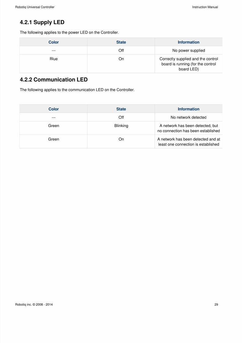
4.2.1 Supply LED
The following applies to the power LED on the Controller.
Color State Information
--- Off No power supplied
Blue On Correctly supplied and the controlboard is running (for the control
board LED)
4.2.2 Communication LED
The following applies to the communication LED on the Controller.
Color State Information
--- Off No network detected
Green Blinking A network has been detected, but
no connection has been established
Green On A network has been detected and at
least one connection is established
7/26/2019 RUC Controlador
http://slidepdf.com/reader/full/ruc-controlador 30/42
Robotiq Universal Controller Instruction Manual
Robotiq inc. © 2008 - 2014 30
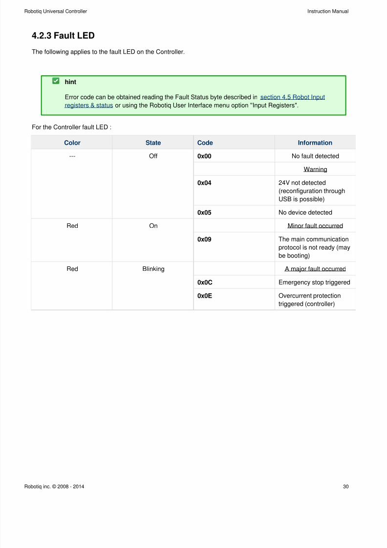
4.2.3 Fault LED
The following applies to the fault LED on the Controller.
hint
Error code can be obtained reading the Fault Status byte described in section 4.5 Robot Input or using the Robotiq User Interface menu option ''Input Registers".registers & status
For the Controller fault LED :
Color State Code Information
--- Off 0x00 No fault detected
Warning
0x04 24V not detected
(reconfiguration throughUSB is possible)
0x05 No device detected
Red On Minor fault occurred
0x09 The main communication
protocol is not ready (may
be booting)
Red Blinking A major fault occurred
0x0C Emergency stop triggered
0x0E Overcurrent protection
triggered (controller)
7/26/2019 RUC Controlador
http://slidepdf.com/reader/full/ruc-controlador 31/42
Robotiq Universal Controller Instruction Manual
Robotiq inc. © 2008 - 2014 31
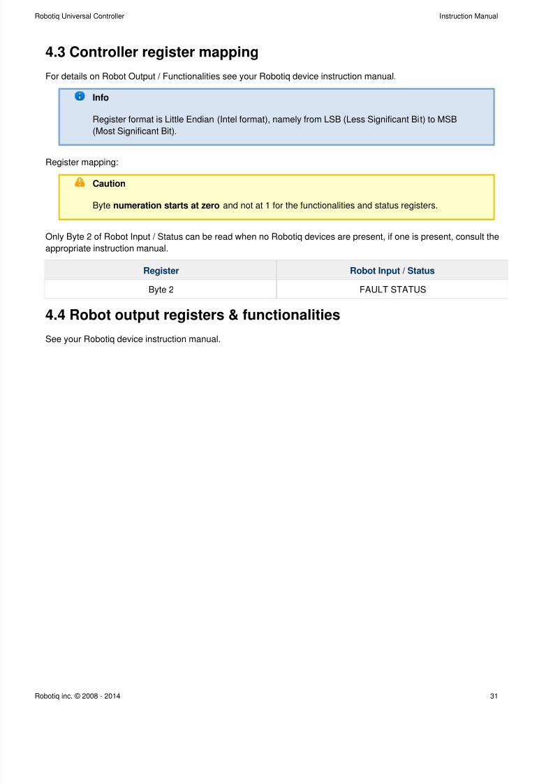
4.3 Controller register mapping
For details on Robot Output / Functionalities see your Robotiq device instruction manual.
Info
Register format is Little Endian (Intel format), namely from LSB (Less Significant Bit) to MSB
(Most Significant Bit).
Register mapping:
Caution
Byte and not at 1 for the functionalities and status registers.numeration starts at zero
Only Byte 2 of Robot Input / Status can be read when no Robotiq devices are present, if one is present, consult the
appropriate instruction manual.
Register Robot Input / Status
Byte 2 FAULT STATUS
4.4 Robot output registers & functionalities
See your Robotiq device instruction manual.
7/26/2019 RUC Controlador
http://slidepdf.com/reader/full/ruc-controlador 32/42
Robotiq Universal Controller Instruction Manual
Robotiq inc. © 2008 - 2014 32
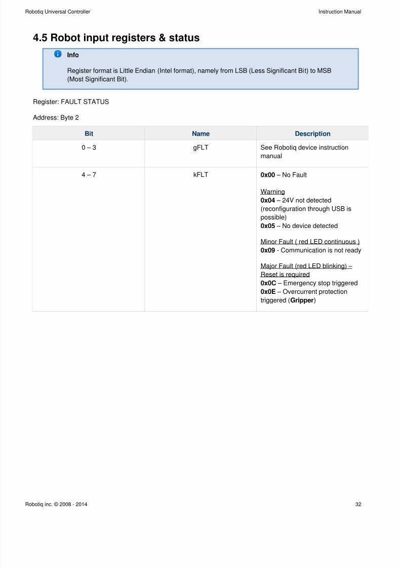
4.5 Robot input registers & status
Info
Register format is Little Endian (Intel format), namely from LSB (Less Significant Bit) to MSB
(Most Significant Bit).
Register: FAULT STATUS
Address: Byte 2
Bit Name Description
0 – 3 gFLT See Robotiq device instruction
manual
4 – 7 kFLT 0x00 – No Fault
Warning
– 24V not detected0x04(reconfiguration through USB is
possible)
– No device detected0x05
Minor Fault ( red LED continuous )
0x09 - Communication is not ready
Major Fault (red LED blinking) –
Reset is required
0x0C – Emergency stop triggered
– Overcurrent protection0x0E
triggered ( )Gripper
7/26/2019 RUC Controlador
http://slidepdf.com/reader/full/ruc-controlador 33/42
Robotiq Universal Controller Instruction Manual
Robotiq inc. © 2008 - 2014 33
5. User Interface
Visit http://support.robotiq.com to get the latest installer for the Robotiq User Interface along with appropriate
documentation.
See the for details on usage of the RUI.Robotiq User Interface Instruction Manual
7/26/2019 RUC Controlador
http://slidepdf.com/reader/full/ruc-controlador 34/42
Robotiq Universal Controller Instruction Manual
Robotiq inc. © 2008 - 2014 34
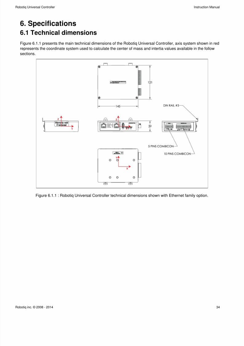
6. Specifications
6.1 Technical dimensions
Figure 6.1.1 presents the main technical dimensions of the Robotiq Universal Controller, axis system shown in red
represents the coordinate system used to calculate the center of mass and intertia values available in the follow
sections.
Figure 6.1.1 : Robotiq Universal Controller technical dimensions shown with Ethernet family option.
7/26/2019 RUC Controlador
http://slidepdf.com/reader/full/ruc-controlador 35/42
Robotiq Universal Controller Instruction Manual
Robotiq inc. © 2008 - 2014 35
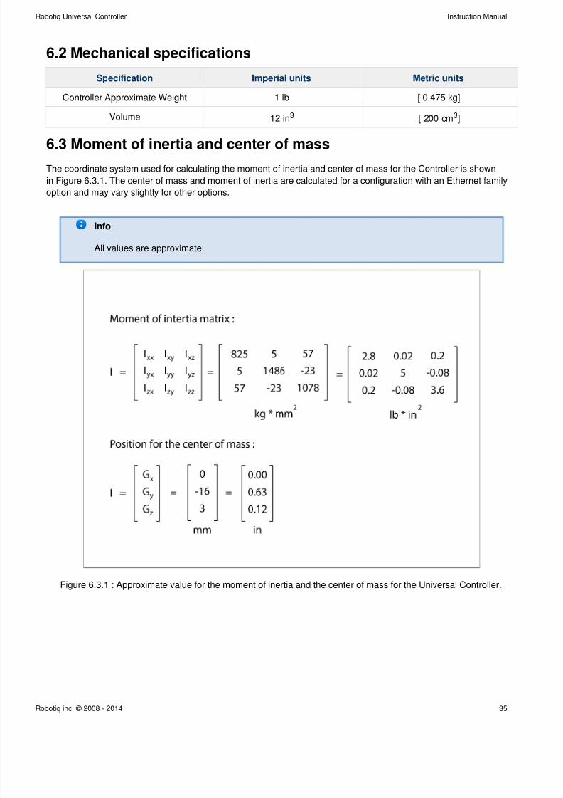
6.2 Mechanical specifications
Specification Imperial units Metric units
Controller Approximate Weight 1 lb [ 0.475 kg]
Volume 12 in3 [ 200 cm ]3
6.3 Moment of inertia and center of mass
The coordinate system used for calculating the moment of inertia and center of mass for the Controller is shown
in Figure 6.3.1. The center of mass and moment of inertia are calculated for a configuration with an Ethernet family
option and may vary slightly for other options.
Info
All values are approximate.
Figure 6.3.1 : Approximate value for the moment of inertia and the center of mass for the Universal Controller.

7/26/2019 RUC Controlador
http://slidepdf.com/reader/full/ruc-controlador 36/42
Robotiq Universal Controller Instruction Manual
Robotiq inc. © 2008 - 2014 36
6.4 Electrical ratings
Below are the Electrical ratings for the Robotiq Universal Controller.
SPECIFICATION VALUE
Operating Supply Voltage 24 V
Absolute Maximum Supply Voltage 28 V
Quiescent Power (minimum power consumption) 3.6 W
Peak Power See your Robotiq device instruction manual
Maximum RMS Supply Current (supply voltage at 24V) 12 A
Emergency stop entry current 50 mA
Emergency stop voltage 24V
7/26/2019 RUC Controlador
http://slidepdf.com/reader/full/ruc-controlador 37/42
Robotiq Universal Controller Instruction Manual
Robotiq inc. © 2008 - 2014 37
7. Maintenance
No maintenance is required on the Universal Controller.
Note
Controller must be kept away from dirty, dust, scraps, chemicals, etc.Always respect the operating conditions.
Tip
It is a good practice to test emergency stop functionnality when doing Robotiq device
maintenance.

7/26/2019 RUC Controlador
http://slidepdf.com/reader/full/ruc-controlador 38/42
Robotiq Universal Controller Instruction Manual
Robotiq inc. © 2008 - 2014 38
8. Spare Parts, Kits and Accessories
Spare parts, kits and accessories list :
The following list is up to date at print time and is subject to change, check for updates.online
Item Description Ordering Number
Standard Universal Controller External Controller for Robotiq
devices, includes Supply Connector
with emergency stop jumper.
Replace XXXX by one of the
following communication protocol
option :
ENIP - Ethernet IP
MTCP - Modbus TCP/IP
ECAT - EtherCAT
DNET - Device Net
CANO - CANopen
PNET - ProfiNET
DPS - ProfiBUS
UNI-CTR-001-XXXX
USB cable 5 m USB 2.0 cable, USB A - A
male.
Meant for configuration of the
Robotiq Universal Controller
communication parameters and
control of Robotiq devices via the
Robotiq User Interface.
CBL-USB-2057
Fieldbus cable Available on demand
7/26/2019 RUC Controlador
http://slidepdf.com/reader/full/ruc-controlador 39/42
Robotiq Universal Controller Instruction Manual
Robotiq inc. © 2008 - 2014 39
1.
a.
b.
2.
a.
b.
c.
3.
a.
b.
c.
4.
a.
b.
c.
i.
ii.
d.
i.
ii.
e.
5.
a.
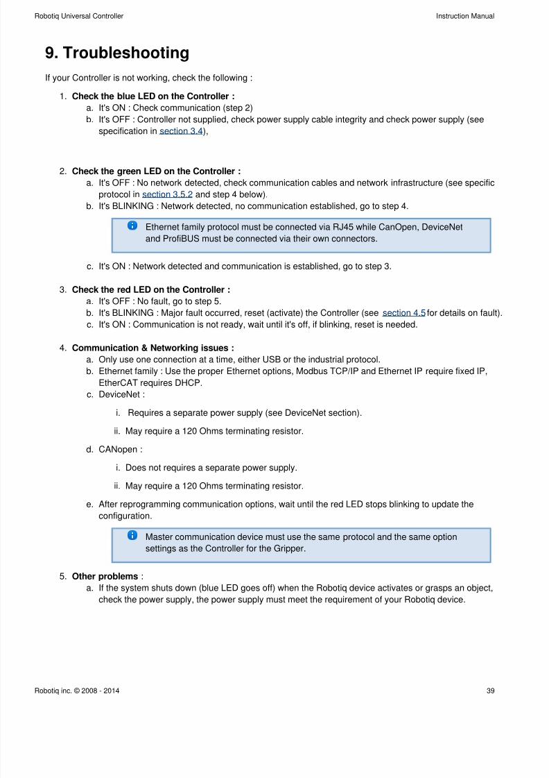
9. Troubleshooting
If your Controller is not working, check the following :
Check the on the Controller :blue LED
It's ON : Check communication (step 2)
It's OFF : Controller not supplied, check power supply cable integrity and check power supply (see
specification in ),section 3.4
Check the on the Controller :green LED
It's OFF : No network detected, check communication cables and network infrastructure (see specific
protocol in and step 4 below).section 3.5.2
It's BLINKING : Network detected, no communication established, go to step 4.
Ethernet family protocol must be connected via RJ45 while CanOpen, DeviceNet
and ProfiBUS must be connected via their own connectors.
It's ON : Network detected and communication is established, go to step 3.
Check the on the Controller :red LED
It's OFF : No fault, go to step 5.
It's BLINKING : Major fault occurred, reset (activate) the Controller (see for details on fault).section 4.5
It's ON : Communication is not ready, wait until it's off, if blinking, reset is needed.
Communication & Networking issues :
Only use one connection at a time, either USB or the industrial protocol.
Ethernet family : Use the proper Ethernet options, Modbus TCP/IP and Ethernet IP require fixed IP,
EtherCAT requires DHCP.
DeviceNet :
Requires a separate power supply (see DeviceNet section).
May require a 120 Ohms terminating resistor.
CANopen :
Does not requires a separate power supply.
May require a 120 Ohms terminating resistor.
After reprogramming communication options, wait until the red LED stops blinking to update the
configuration.
Master communication device must use the same protocol and the same option
settings as the Controller for the Gripper.
:Other problems
If the system shuts down (blue LED goes off) when the Robotiq device activates or grasps an object,
check the power supply, the power supply must meet the requirement of your Robotiq device.
7/26/2019 RUC Controlador
http://slidepdf.com/reader/full/ruc-controlador 40/42
Robotiq Universal Controller Instruction Manual
Robotiq inc. © 2008 - 2014 40
1.
2.
3.
1.
2.
3.
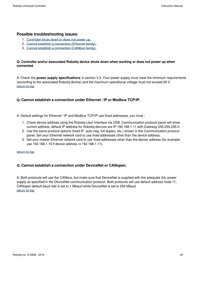
Possible troubleshooting issues:
Controller shuts down or does not power up.
Cannot establish a connection (Ethernet family).
Cannot establish a connection (CANbus family).
Q: Controller and/or associated Robotiq device shuts down when working or does not power up whenconnected.
A: Check the in section 3.3. Your power supply must meet the minimum requirementspower supply specifications
(according to the associated Robotiq device) and the maximum operational voltage must not exceed 26 V.
return to top
Q: Cannot establish a connection under Ethernet / IP or Modbus TCP/IP.
A: Default settings for Ethernet / IP and Modbus TCP/IP use fixed addresses, you must :
Check device address using the Robotiq User Interface via USB. Communication protocol panel will show
current address, default IP address for Robotiq devices are IP 192.168.1.11 with Gateway 255.255.255.0.
Use the same protocol options (fixed IP, auto-neg, full duplex, etc.) shown in the Communication protocol
panel. Set your Ethernet network card to use fixed addresses other than the device address.
Set your master Ethernet network card to use fixed addresses other than the device address (for example
use 192.168.1.10 if device address is 192.168.1.11).
return to top
Q: Cannot establish a connection under DeviceNet or CANopen.
A: Both protocols will use the CANbus, but make sure that DeviceNet is supplied with the adequate 24v power
supply as specified in the DeviceNet communication protocol. Both protocols will use default address node 11.
CANopen default baud rate is set to 1 Mbaud while DeviceNet is set to 250 kBaud.
return to top
7/26/2019 RUC Controlador
http://slidepdf.com/reader/full/ruc-controlador 41/42
Robotiq Universal Controller Instruction Manual
Robotiq inc. © 2008 - 2014 41
10. Warranty
Robotiq warrants the Unviersal Controller against defects in material and workmanship for a period of one year from
the date of reception when utilized as intended with the specified maintenance. Robotiq also warrants that this
equipment will meet applicable specifications under normal use.
Warranty applies under the following conditions:
Usage respects the operating and storage conditions specified in section 3.2
Usage under normal one-shift operation (40h a week)
Usage respect maintenance specified in .section 7
During the warranty period, Robotiq will repair or replace any defective product, as well as verify and adjust the
product free of charge if the equipment should need to be repaired or if the original adjustment is erroneous. If the
equipment is sent back for verification during the warranty period and found to meet all published specifications,
Robotiq will charge standard verification fees.
The unit is considered defective when at least one of the following conditions occurs:
The Controller standard USB communication is not accessible;
The Controller optional communication is not accessible;
The Robotiq device feedback necessary for the robot program is not accessible.
Caution
The warranty will become null and void if the:
Unit has been tampered with, repaired or worked on by unauthorized individuals.
Warranty sticker has been removed.
Screws, other than as explained in this guide, have been removed.
Unit has been opened other than as explained in this guide.Unit serial number has been altered, erased, or removed.
Unit has been misused, neglected, or damaged by accident.
This warranty is in lieu of all other warranties expressed, implied, or statutory, including, but not limited to, the
implied warranties of merchantability and fitness for a particular purpose. In no event shall Robotiq be liable for
special, incidental, or consequential damages.
Robotiq shall not be liable for damages resulting from the use of the product, nor shall Robotiq be responsible for
any failure in the performance of other items to which the product is connected or the operation of any system of
which the product may be a part.
Exclusion
Robotiq reserves the right to make changes in the design or construction of any of its products at any time without
incurring obligation to make any changes whatsoever on units already purchased.
This warranty excludes failure resulting from: improper use or installation, normal wear and tear, accident, abuse,
neglect, fire, water, lightning or other acts of nature, causes external to the product or other factors beyond Robotiq's
control.
7/26/2019 RUC Controlador
http://slidepdf.com/reader/full/ruc-controlador 42/42
Robotiq Universal Controller Instruction Manual
11. Contact
www.robotiq.com
Go to Contact Us
Phone
1-888-ROBOTIQ (762-6847)1-418-800-0045 (outside US and Canada)
Fax
1-418-800-0046
Technical support and Engineering
extension 207
Sales US
extension 122
Head officeRobotiq:
966, chemin Olivier
Suite 325
St-Nicolas, Qc
G7A 2N1
Canada