r&s®tsmw universal radio network analyzer measurement ... · in addition to these values, the...
TRANSCRIPT

R&S®TSMW Universal Radio Network AnalyzerScanner for drive tests and I/Q streaming
Te
st &
Mea
sure
men
t
Prod
uct B
roch
ure
| 07.
00R&S®TSMW Universal Radio Network AnalyzerScanner for drive tests and I/Q streaming

2
R&S®TSMW Universal Radio Network AnalyzerAt a glanceThe R&S®TSMW universal radio network analyzer is a platform for optimizing all conventional wireless communications networks. Two frontends for any input frequency from 30 MHz to 6 GHz, a preselection and a software-defined architecture offer unsurpassed performance while providing maximum flexibility. In addition to functioning as a scanner for wireless communications networks, the R&S®TSMW is also an ideal digital I/Q baseband receiver.
Owing to its hardware platform, the R&S®TSMW universal radio network analyzer offers maximum flexibility. For example, the R&S®TSMW comes in handy as an LTE scanner, and it can be utilized together with the R&S®ROMES4 drive test software to roll out and optimize 3GPP EUTRA networks. In addition to LTE, other wireless communications technologies such as GSM, WCDMA,CDMA2000® 1xEV-DO,TETRAandWiMAX™are supported simultaneously.
Moreover, the R&S®TSMW can be used as a realtime scannerforI/Qbasebanddata.TheR&S®TSMW-K1option offers a MATLAB® and a C++ interface via which I/Q measurement data can be captured and evaluated.
Key facts ❙ User-definableinputfrequencyrangefrom30 MHzto6 GHz
❙ Two independent RF and signal processing paths, each withabandwidthofupto20MHz
❙ Integrated preselection for high intermodulation suppression while dynamic range is high
❙ Support of LTEFDD and TDLTE ❙ Parallel measurements in GSM, WCDMA, LTE, CDMA2000®1xEV-DO,TETRAandWiMAX™networkswith the R&S®ROMES4 drive test software
❙ Spectrum measurements with the RF power scan option ❙ I/Q baseband streaming and capturing ❙ Integrated GPS

Rohde & Schwarz R&S®TSMW Universal Radio Network Analyzer 3
R&S®TSMW Universal Radio Network AnalyzerBenefits and key features
LTE and MIMO network rollout and network optimization ❙ Automatic detection and measurement of all available cells
❙ MIMO-specificmeasurementsshowMIMOgain ❙ Intersymbol interference analysis with multipath measurements
❙ Wideband and narrowband measurements ❙ Support of LTEFDD and TDLTE ▷ page 4
Parallel support of multiple wireless communications technologies ❙ Simultaneous measurements in GSM, LTE, WCDMA, CDMA2000®1xEV-DO,TETRAandWiMAX™
❙ Simple scanner setup ❙ Flexible assignment of the two receivers for maximum measurement speed
❙ Everything in one instrument ▷ page 9
All-in-one drive test solution with R&S®ROMES4 ❙ Network optimization with scanner and test terminal ❙ Improvement of QoS ▷ page11
Maximum flexibility when evaluating I/Q data ❙ Seamless streaming of I/Q data in realtime ❙ I/Q recording via LAN to the PC or via Rohde & Schwarz I/Q interface to the R&S®IQR
❙ Data access via MATLAB® or C++ interface ❙ Fast integration due to included example application based on MATLAB® ▷ page12
Unsurpassed hardware platform performance and flexibility ❙ Broadbandwith20 MHzbandwidthandmaximumfrequencyrangefrom30 MHzto6 GHz
❙ Maximumconfigurationflexibility ❙ Top dynamic range and measurement accuracy owing to adaptive preselection
❙ Update of hardware platform via software ❙ Integrated SuperSense GPS with PPS ❙ R&S®TSMF special solution ▷ page14
CDMA2000® is a registered trademark of the Telecommunications Industry Association (TIAUSA)."WiMAXForum"isaregisteredtrademarkoftheWiMAXForum."WiMAX",theWiMAXForumlogo,"WiMAXForumCertified",andtheWiMAXForumCertifiedlogoaretrademarksoftheWiMAXForum.

4
LTE and MIMO network rollout and network optimizationUsing the R&S®TSMW together with the R&S®ROMES4 drive test software opens the door to numerous measurement and analysis capabilities for LTE field tests.
Automatic detection and measurement of all available cellsAll that the R&S®ROMES4 software needs to "know” is thecenterfrequencyofanLTEsignal.TheR&S®TSMWcanfindallfurtherinformationthatisrequired,e.g.thebandwidth used, the physical cell ID, the eNodeB cell ID, the cyclic prefix length, or the synchronization channels (P-SCHandS-SCH)andRSRP/RSRQ/RS-SINRvalues.This is particularly relevant when a wireless communications network is growing both in size and complexity. Theuserdoesnotrequireanydetailedknowledgeaboutthe LTE network and its structure when carrying out measurements.
Immediately after the measurement is started, the power values of the physical cell IDs are displayed in a Top N chart.
In addition to these values, the RSRP, RSRQ and the narrowband and wideband signaltointerferenceplusnoise ratio (SINR) are output. These values indicate whether interference is present on a signal. The measurement results can be output at a maximum rate of 200 measurements per second.
Condition number per resource block.

Rohde & Schwarz R&S®TSMW Universal Radio Network Analyzer 5
T×1
T×2
R×1T×1
T×2
T×1
T×2
T×1:R×1 T×1:R×2T×2:R×1 T×2:R×2
R×2
Subc
arrie
rs
Symbols
Subc
arrie
rs
Symbols
R1
R1
R1
R1
R1
R1
R1
R1
R1
R1
R1
R1
R1
R1
R1
R1
MIMO configuration
MIMO-specific measurements show MIMO gainA special MIMO measurement using the two internal R&S®TSMW receivers measures the true MIMO gain under realworld conditions. Two antennas simultaneously measure the LTE signal, making it possible to determine the degree of correlation of the MIMO channel. This indicates whether MIMO can profitably be used in the measured area and whether investments to expand the infrastructure will pay off.
The MIMO measurement function can be used for 4x2 and 2x2 systems. All measurements are based on the channelmatrixHwiththecomplexamplitudeandphasevalues. The matrix is output for each measured cell and resource block. The condition number calculated from the matrices obtained gives a good idea of the degree of correlation of a MIMO channel. A value in the range of 0 dBto15dB,forexample,indicatesgoodconditionsforLTE MIMO.
R&S®ROMES allows the measurement data to be output to a text file for further processing. MIMOspecific measurements are useful for the following applications: ❙ DetermininginwhatareasMIMOcanprofitablybeused ❙ Determining whether additional investments for MIMO will pay off
❙ Optimizing MIMO performance ❙ Reproducing LTE signal channels in the lab under realworld conditions

6
Typical configuration of an LTE drive test system consisting
of an R&S®TSMW and the R&S®ROMES4 software.
Intersymbol interference analysis with multipath measurementsBy means of the channel impulse response measurement, the R&S®TSMW can measure multipath propagation and reflections and then display the results by using the R&S®ROMES4 software. Reflections can be measured in a timeframeof–6 µsto+34 µs.Thismeansthattheeight-fold length of a normal cyclic prefix can be measured. As a result, the user can detect violations of the guard interval (intersymbol interference, ISI).
A further interference factor may be excessively high base station phase noise. The R&S®TSMW’s low inherent phase noise allows users to also detect problems in the base station.
Wideband and narrowband measurementsThe R&S®TSMW automatically recognizes the bandwidth of the LTE signal. Based on this information, fast narrowband measurements and slower wideband measurements are output simultaneously. Wideband measurements are especially important to detect any interference caused by externalsourcessuchasTVtransmitters,repeaters,jammers and narrowband interferers.
Narrowband WidebandReceived power Power RSRP
BasedonSCH(62SC1)) Based on full RS 2) bandwidth
Quality RSRQ RSRQ
BasedonPBCH(72SC) Based on full RS bandwidth
SNR SINR RSSINR
BasedonSCH(62SC) Based on full RS bandwidth
Total power Ptotal RSSI
BasedonSCH(62SC) Based on full RS bandwidth
Equipment required for LTE drive tests
❙ R&S®TSMW universal radio network analyzer
❙ R&S®TSMWK29 LTE scanner option
❙ R&S®TSMWK30 LTE MIMO scanner option
❙ R&S®TSMW-Z1powersupply ❙ R&S®ROMES4 drive test software
❙ R&S®ROMES4T1WR&S®TSMWall-technologydriverfor
R&S®ROMES
❙ R&S®ROMES4LTS LTE Samsung driver
❙ R&S®ROMES4LTQ LTE Qualcomm driver 1) SC: synchronization channel.2) RS: reference signal.

Rohde & Schwarz R&S®TSMW Universal Radio Network Analyzer 7
Of particular interest is the SINR of the reference signal (RSSINR), which is measured for each resource block, cell and antenna. This measurement shows interference and itsspectralposition,makingitpossibletoquicklytracethe causes of interference. The figure to the left shows the paths of a 2x2 or 4x2 LTE system as a waterfall diagram, making changes over time visible. A marker allows the usertoquicklyfindtheresourceblockandfrequencyfromwhich interference originates, as well as the associated RSSINR and time stamp.
Support of LTE-FDD and TD-LTEThe R&S®TSMW can also perform FDD and TDD measurements. Measurements can be carried out in parallel in the TDDfrequencybands33to43andtheFDDfrequencybands1to25.
There are no additional costs for TDLTE and other frequencybands,makingtheR&S®TSMWaninvestmentforthe future – with maximum flexibility.
TopN with narrowband, wideband and MIMO values.
Wideband RSSINR per resource block and per antenna.

Bands and tech-nologies sup-ported by the R&S®TSMW
E-UTRA operating band
Uplink (UL) operating band BS: receive UE: transmit
Downlink (DL) operating bandBS: transmit UE: receive
Duplex mode
● 1 1920MHz to 1980MHz 2110MHz to 2170MHz FDD
● 2 1850MHz to 1910MHz 1930MHz to 1990MHz FDD
● 3 1710MHz to 1785MHz 1805MHz to 1880MHz FDD
● 4 1710MHz to 1755MHz 2110MHz to 2155MHz FDD
● 5 824MHz to 849MHz 869MHz to 894MHz FDD
● 61 830MHz to 840MHz 875MHz to 885MHz FDD
● 7 2500MHz to 2570MHz 2620MHz to 2690MHz FDD
● 8 880MHz to 915MHz 925MHz to 960MHz FDD
● 9 1749.9MHz to 1784.9MHz 1844.9MHz to 1879.9MHz FDD
● 10 1710MHz to 1770MHz 2110MHz to 2170MHz FDD
● 11 1427.9MHz to 1447.9MHz 1475.9MHz to 1495.9MHz FDD
● 12 699MHz to 716MHz 729MHz to 746MHz FDD
● 13 777MHz to 787MHz 746MHz to 756MHz FDD
● 14 788MHz to 798MHz 758MHz to 768MHz FDD
● 15 Reserved Reserved FDD
● 16 Reserved Reserved FDD
● 17 704MHz to 716MHz 734MHz to 746MHz FDD
● 18 815MHz to 830MHz 860MHz to 875MHz FDD
● 19 830MHz to 845MHz 875MHz to 890MHz FDD
● 20 832MHz to 862MHz 791MHz to 821MHz FDD
● 21 1447.9MHz to 1462.9MHz 1495.9MHz to 1510.9MHz FDD
...
● 23 2000MHz to 2020MHz 2180MHz to 2200MHz FDD
● 24 1626.5MHz to 1660.5MHz 1525MHz to 1559MHz FDD
● 25 1850MHz to 1915MHz 1930MHz to 1995MHz FDD
...
● 33 1900MHz to 1920MHz 1900MHz to 1920MHz TDD
● 34 2010MHz to 2025MHz 2010MHz to 2025MHz TDD
● 35 1850MHz to 1910MHz 1850MHz to 1910MHz TDD
● 36 1930MHz to 1990MHz 1930MHz to 1990MHz TDD
● 37 1910MHz to 1930MHz 1910MHz to 1930MHz TDD
● 38 2570MHz to 2620MHz 2570MHz to 2620MHz TDD
● 39 1880MHz to 1920MHz 1880MHz to 1920MHz TDD
● 40 2300MHz to 2400MHz 2300MHz to 2400MHz TDD
● 41 2496MHz 2690MHz 2496MHz 2690MHz TDD
● 42 3400MHz to 3600MHz 3400MHz to 3600MHz TDD
● 43 3600MHz to 3800MHz 3600MHz to 3800MHz TDD
8

Rohde & Schwarz R&S®TSMW Universal Radio Network Analyzer 9
Parallel support of multiple wireless communications technologiesThe R&S®TSMW can be adapted to the customer's application by using various options. Together with the R&S®ROMES4 software, up to seven different technologies can be measured and displayed at the same time, while the hardware resources can be scaled as needed.
Simultaneous measurements in GSM, LTE, WCDMA, CDMA2000® 1xEV-DO, TETRA and WiMAX™Multiple wireless communications technologies are often used simultaneously. Particularly during the rollout ofnewtechnologiessuchas3GPPLTEorWiMAX™IEEE802.16e,wirelesscommunicationsnetworkssuchasGSM/WCDMA,CDMA2000®1xEV-DOorTETRAare already present. To keep the T & M effort and the related costs low, an allinone solution should be used. Rohde & Schwarz offers the perfect solution with its R&S®TSMW and the R&S®ROMES4 software.
Simple scanner setupTheusergenerallydoesnotrequireexpertknowledgeabout the wireless communications network to be tested. The R&S®TSMW detects all important information automatically. For example, the user only has to enter the following parameters: the UARFCN number in a WCDMA network,thebandinaGSMnetwork,thecenterfrequencyinaWiMAX™orLTEnetwork,andthechannelnumberinaCDMA2000®1xEV-DOnetwork.TheR&S®TSMWthenautomatically detects and measures all detectable scrambling codes, channels, preamble indices and physical cell IDs.Themeasurementspeedisnotaffectedbythequantity of measured signals. Similarly for TETRA, all active channelsina15MHzdownlinkbandaredetectedand decoded automatically.
Flexible assignment of the two receivers for maximum measurement speedTechnologies to be measured can flexibly be distributed to two RF and signal paths. Measuring two techno logies in parallel does not cause any reduction in measurement speed. If further technologies are added, they are timedistributed to the hardware resources. This feature enables the R&S®TSMW to offer maximum performance in multipletechnology measurements. Up to seven wireless communications technologies can be measured at the same time.

10
Everything in one instrument Wireless communications scanners such as the R&S®TSMW are primarily used when measurements must be performed independently of a test terminal. The R&S®ROMES4 software offers a Top N evaluation of all available signals for each technology. The user receives an overview of the strongest signals and can sort them by provider. Especially in CDMA2000® and WCDMA networks, this evaluation plays a crucial role in reducing pilot pollution.
Furthermore, neighbor cells that may not be found by a test terminal can be detected. Missing neighbor cells can be detected independently of the technology. This enables the user to identify coverage gaps or interference. The capability to demodulate the broadcast information of the broadcastchannel(BCH)offersinsightintothenetworkconfiguration. Applications such as automatic neighborhood analysis or automatic interference detection can easily be carried out by applying this functionality.
The RF spectrum scan running in parallel additionally supports finding external interferences. Moreover, the function is very useful in spectrum clearing, in refarming and in using the digital dividend.
The R&S®TSMW can also be used for benchmark purposes. Multiple technologies and multiple providers can be scanned simultaneously. Even when a new technology is being rolled out, already present networks can be monitored as well.
Technologies supported by the R&S®TSMW
SIB decoding
GSM ● ●
WCDMA ● ●
CDMA2000® ● ●
1xEV-DO (Rel.0/Rev.A/Rev.B)
● ●
WiMAX™IEEE802.16e ● ●
TDLTE ● AvailableasofH1/2012
LTE FDD ● ●
TETRA ● ●

Rohde & Schwarz R&S®TSMW Universal Radio Network Analyzer 11
All-in-one drive test solution with R&S®ROMES4When used together with the R&S®TSMW, the R&S®ROMES4 drive test software also supports test terminals. The R&S®TSMW can be used to detect and eliminate mobile radio network errors indicated by a terminal.
Technology Option3GPP LTE MIMO R&S®TSMWK30
3GPP LTE R&S®TSMWK29
WiMAX™IEEE802.16e R&S®TSMW-K28
GSM/WCDMA R&S®TSMW-K21
CDMA2000®1xEV-DORev.B R&S®TSMWK22
TETRA R&S®TSMWK26
RF power scan R&S®TSMW-K27
When combined with R&S®ROMES4, the R&S®TSMW can be used with
the technologies listed in the following table.
Typical drive test configuration
Test terminal R&S®ROMES software
Network optimization with scanner and test terminalThe R&S®ROMES4 drive test software not only evaluates measurement data from Rohde & Schwarz scanners. It also covers test terminals. These terminals establish either a voice or a data link. For example, a voice connection enablestheusertomeasurespeechqualityortogeneratea statistical evaluation about dropped calls. In the case of data links, the maximum possible transmission rate must be achieved. This is verified by means of data services such as an FTP download.
Improvement of QoSExample: LTEDuring an FTP download, a test terminal displays the maximum current data transmission rate. If this rate is too low with regard to the wireless communications technology beingused,thechannelqualityindicator(CQI)measuredby the test terminal can be used to trace the cause of the problem.
If the CQI is too low, either the received signal may be too weak or the measured SINR may be very low. In this case, the test terminal will not be able to use any higherorder modulation types such as 64QAM. The R&S®TSMW can detect and identify such trouble spots independently of the terminal. If the received signals are too weak, this may indicate that the test terminal did not find a neighbor cell. The R&S®TSMW is networkindependent because it does not rely on neighbor lists. Unknown neighbor cells can therefore be detected without any problem. Even automatic neighbor relation (ANR) algorithms that are used by selforganizing networks (SON) can be verified.

12
Maximum flexibility when evaluating I/Q data
Seamless streaming of I/Q data in realtimeAspecialassetoftheR&S®TSMWisitsR&S®TSMW-K1digital I/Q data interface. Users of this option can, for example, perform technologyindependent channel measurements. These measurements can be used to simulate realistic fading scenarios in a lab environment. The recorded I/Q data can either be replayed in the lab using a Rohde & Schwarz signal generator or analyzed using the MATLAB®/C++ interface. I/Q data can be recorded in two ways. One, the R&S®TSMW can be connected with a PC via a LAN interface. Two, the data can be recorded with the R&S®IQR via the Rohde & Schwarz I/Q interface. The higher data rate of the Rohde & Schwarz I/Q interface makes it possible to record both frontends of the R&S®TSMWwithupto2×20MHzinsteadofusinga20 MHzI/Qmeasurementbandwidth.
To facilitate I/Q data analysis, the GPS data are saved together with the I/Q data. The R&S®TSMW offers a truly mobile solution for recording all types of RF signals.
I/Q streaming via LAN (1)For this application, the R&S®TSMW and a highperformance PC are connected via Gigabit Ethernet. This interfaceallowsamaximumstreambandwidthof20MHz.The measured data is stored on a fast hard disk. It can be replayed as a waveform on a Rohde & Schwarz signal generator or analyzed via MATLAB®. In addition to offering a MATLAB®based GUI for controlling the recording, theR&S®TSMW-K1optionalsoincludesaMATLAB®andaC++ interface.Theseinterfacespermitsimpleaccessto the I/Q data after the measurement or in realtime. The recording time is limited only by the size of the hard disk. Aharddiskwithawritespeedofatleast80Mbyte/sisrecommended to avoid any problems.
I/Q streaming via Rohde & Schwarz I/Q interface (2)Due to its higher transmission bandwidth, the Rohde & Schwarz I/Q interface enables I/Q streaming with 1×20MHzbandwidth(2×20MHzinfuturerelease).TheR&S®TSMW is directly connected with the R&S®IQR and is operated via the R&S®IQR touchscreen.
The I/Q data stored on the removable hard disks of the R&S®IQR can be output to a host PC via Gigabit Ethernet for offline analysis. All Rohde & Schwarz instruments with a Rohde & Schwarz I/Q interface, e.g. a signal generator, can be connected via the digital I/Q interface.
The R&S®IQR enables a recording time of one to three hoursdependingonthedigitalwordlength(8,12,16or20 bit).

Rohde & Schwarz R&S®TSMW Universal Radio Network Analyzer 13
Two ways to record I/Q data: I/Q data can be analyzed on a PC or replayed on a signal generator.
I/Q data
via Rohde & Schwarz interface
RF signal
(1) Record I/Q data with max. 20 MHz bandwidth
(2) Record and replay I/Q data with 1 × 20 MHz bandwidth (2 × 20 MHz in future release)
¸TSMW
DUT
¸IQR
PC
I/Q data
Gbit LAN I/Q interface
¸TSMW
Signal generator
Recording of I/Q data
Application examples ❙ Navigation: Recording of GPS/GLONASS/Galileo signals in different regions. Recorded signals can be replayed under controlled conditions in the lab. This results in faster timetomarket for GPS receivers and mobile phones
❙ Broadcasting:RecordingofTV/FMsignalsduringadrive test. Recorded signals can be replayed under lab conditionstotestTV/FMreceivers
❙ LTE MIMO and LTEAdvanced: Channel measurements for4x2MIMOscenariosandsubsequentanalysis,e.g.using MATLAB®
Equipment required for I/Q recording (1) ❙ R&S®TSMW universal radio network analyzer ❙ R&S®TSMW-K1digitalI/Qsoftwareoption ❙ R&S®TSMW-Z1ACpowersupply ❙ PCwithGigabitLANinterfaceandsupportofjumboframes
❙ HarddiskwithSATAinterfaceandmin.datawriterateof80Mbyte/s
Equipment required for I/Q recording (2) ❙ R&S®TSMW universal radio network analyzer ❙ R&S®TSMW-K1digitalI/Qsoftwareoption ❙ R&S®TSMW-B1Rohde&SchwarzI/Qinterface ❙ R&S®TSMW-Z1ACpowersupply ❙ R&S®IQR100I/Qdatarecorder ❙ R&S®IQR-B110memorypack

14
Unsurpassed hardware platform performance andflexibility
Broadband with 20 MHz bandwidth and maximum frequency range from 30 MHz to 6 GHzThe R&S®TSMW universal radio network analyzer offers a hardware platform with maximum flexibility. The two integratedbroadbandreceivers(30 MHzto6 GHz)withabandwidthof20 MHzeachandaseparatepreselectionopen the door to a variety of applications.
These features allow the R&S®TSMW to cover all existing andfuturefrequencybandswithoutanyadditionalupgrade costs.
Maximum configuration flexibilityThe R&S®TSMW contains two independent receivers withabandwidthof20MHzeach.Thetworeceiverscan be used for different technologies or they can share the measurement tasks for a single technology, such as scanning and demodulating system information blocks (SIBs). This case is particularly interesting when the maximum scan rate needs to be achieved. For LTE MIMOspecific measurements, the two receivers are controlled simultaneously.
Insomecases,onlyonereceiverisrequired,whichiswhy the R&S®TSMW is also available as a singlechannel model. A software option allows the second receiver to bequicklyandeasilyactivatedatalaterpointintime.Although it consumes 30 % less power, the singlechannel R&S®TSMW provides the full range of functions.
Architecture of the dual-channel ¸TSMW universal radio network analyser
Signal processing unit
Signal processing unit
Processor board
GbitPreselection and antenna switch
Frontend 1
Frontend 2
Power board GPS
DMA
GPS

Rohde & Schwarz R&S®TSMW Universal Radio Network Analyzer 15
Top dynamic range and measurement accuracy owing to adaptive preselectionTo achieve top measurement accuracy and dynamic range, the R&S®TSMW has an integrated preselection. Thus, multipleadjustablefiltersreduceintermodulationinadvance.The analyzer can therefore detect signals with a sensitivity that is considerably below the noise level (noise figure 7 dBat3.5 GHz).
Update of hardware platform via softwareThe hardware platform can be updated and its functionality enhanced by means of software. This allows the R&S®TSMW to be expanded in the field to handle additional technologies without having to be sent in for an upgrade.Onlythespecificoptionsrequiredareadded,forexample when the user wants to add LTE or LTE MIMO to the existing GSM/WCDMA function.
Integrated SuperSense GPS with PPSAnintegratedSuperSenseGPSreceiverwith16 channelsandarefreshrateof4 Hzallowstheanalyzertobeusedalso in areas with weak GPS signals. The R&S®TSMW does not need a GPS signal to perform indoor measurements. GPS can improve synchronization, but it is not absolutely necessary.
R&S®TSMF special solution The R&S®TSMF is a special model of the R&S®TSMW that does not permit any I/Q measurements with the R&S®TSMW-K1option.Allotherfunctionsarefully available.
16
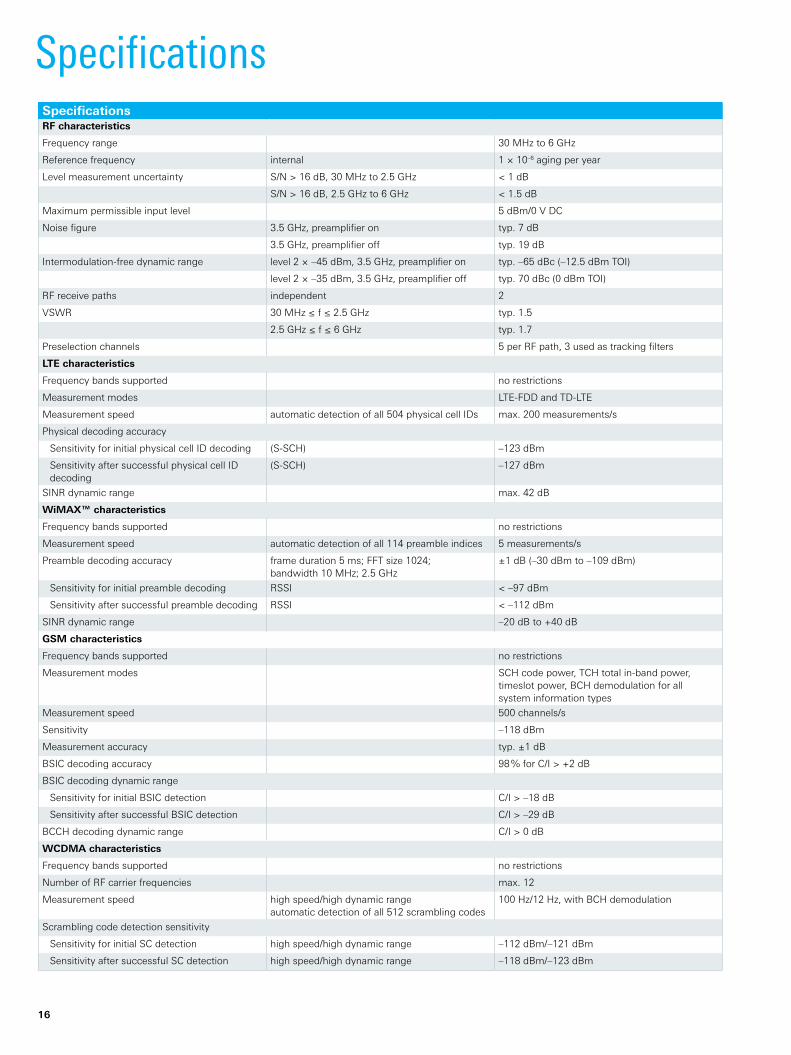
SpecificationsSpecificationsRF characteristics
Frequencyrange 30 MHzto6 GHz
Referencefrequency internal 1×10⁻⁶ aging per year
Level measurement uncertainty S/N>16 dB,30 MHzto2.5 GHz <1 dB
S/N>16 dB,2.5 GHzto6 GHz <1.5 dB
Maximum permissible input level 5 dBm/0VDC
Noise figure 3.5 GHz,preamplifieron typ.7 dB
3.5 GHz,preamplifieroff typ.19 dB
Intermodulationfree dynamic range level2×–45 dBm,3.5 GHz,preamplifieron typ.–65 dBc(–12.5 dBmTOI)
level2×–35 dBm,3.5 GHz,preamplifieroff typ.70 dBc(0 dBmTOI)
RF receive paths independent 2
VSWR 30 MHz≤f≤2.5 GHz typ.1.5
2.5 GHz≤f≤6 GHz typ.1.7
Preselection channels 5perRFpath,3usedastrackingfilters
LTE characteristics
Frequencybandssupported no restrictions
Measurement modes LTEFDD and TDLTE
Measurement speed automaticdetectionofall504physicalcellIDs max. 200 measurements/s
Physical decoding accuracy
Sensitivity for initial physical cell ID decoding (S-SCH) –123 dBm
Sensitivity after successful physical cell ID decoding
(S-SCH) –127 dBm
SINR dynamic range max.42 dB
WiMAX™ characteristics
Frequencybandssupported no restrictions
Measurement speed automaticdetectionofall114preambleindices 5measurements/s
Preamble decoding accuracy frameduration5ms;FFTsize1024;bandwidth10 MHz;2.5 GHz
±1 dB(–30 dBmto–109 dBm)
Sensitivity for initial preamble decoding RSSI <–97 dBm
Sensitivity after successful preamble decoding RSSI <–112 dBm
SINR dynamic range –20 dBto+40 dB
GSM characteristics
Frequencybandssupported no restrictions
Measurement modes SCHcodepower,TCHtotalin-bandpower,timeslotpower,BCHdemodulationforall system information types
Measurement speed 500channels/s
Sensitivity –118 dBm
Measurement accuracy typ.±1 dB
BSIC decoding accuracy 98%forC/I>+2 dB
BSIC decoding dynamic range
Sensitivity for initial BSIC detection C/I>–18dB
Sensitivity after successful BSIC detection C/I > –29 dB
BCCHdecodingdynamicrange C/I>0 dB
WCDMA characteristics
Frequencybandssupported no restrictions
NumberofRFcarrierfrequencies max.12
Measurement speed high speed/high dynamic rangeautomaticdetectionofall512scramblingcodes
100Hz/12Hz,withBCHdemodulation
Scrambling code detection sensitivity
Sensitivity for initial SC detection high speed/high dynamic range –112dBm/–121dBm
Sensitivity after successful SC detection high speed/high dynamic range –118dBm/–123dBm

Rohde & Schwarz R&S®TSMW Universal Radio Network Analyzer 17
SpecificationsScrambling code detection accuracy RSCP typ.<1 dB
Ec/I0>–12 dB typ.<1.5 dB
Scrambling code false detection (ghost code) <10–9
Dynamic range Ec/I0 –22 dB/–30 dB
Min.BCHdemodulationthresholdEc/I0 >–17 dB
CDMA2000® characteristics
Frequencybandssupported no restrictions
NumberofRFcarrierfrequencies max.18
Measurement speed automaticdetectionofall512PNcodes 10Hz
PN detection sensitivity –119 dBm
Dynamic range Ec/I0 29 dB
1xEV-DO characteristics (Rel.0/Rev.A/Rev.B)
Frequencybandssupported no restrictions
NumberofRFcarrierfrequencies max.18
Measurement speed 10Hz
PN detection sensitivity –120 dBm
Dynamic range Ec/I0 33 dB
TETRA characteristics
TETRA bands supported no restrictions
NumberofRFcarrierfrequencies withina10MHzdownlinkband max. 400
Channel resolution 25kHz(QPSK)
Measurement speed max.8000channels/s,20/sfora10 MHzblock
Sensitivity RSSI measurements –120dBm
TETRABSCHdecoding(BSCHdecodingforchannelswithanSNR>9.5 dB)
–115dBm
I/Q characteristics (requires R&S®TSMW-K1)
Digital filter bandwidth, burst 800kHzto20 MHz
Digital filter bandwidth, streaming hardwarerequirements:GbitLANlink,jumboframes,harddisktransferrate80 Mbyte/s
max. 22 Msample/s
Resampling rate 1Msample/sto21.94Msample/s
Demodulation bandwidth 20 MHz
I/Q buffer size 200 Mbyte
Gbit LAN I/Q interface
Data format 14bitADCresolution 8/12/16or20bit
R&S®Digital I/Q interface (additionally requires R&S®TSMW-B1) 1)
Interface clock rate 71.4MHz,fixed
level LVDS
connector 26pin MDR
Data format channellinkprotocol:clockratemax.22.1MHz 20 bit
Source interfacemode1(enablemode) frontend1and2
RF power scan
Frequencyrange 30MHzto6GHz
Resolution bandwidths 140Hzto1.438MHz
Sensitivity 22.4kHzRBW,RMS,at900MHz
preamplifier off –107dBm
preamplifier on –116dBm
140HzRBW,RMS,at900MHz
preamplifier off –129dBm
preamplifier on –138dBm
Scan speed 180kHzresolution,100MHzspan,20MHzbandwidth 2)
130Hz
11.23kHzresolution,10MHzspan,10MHzbandwidth 2)
690Hz
140Hzresolution,1MHzspan,1MHzbandwidth 2)
64Hz

18
SpecificationsMax.numberoffrequencyranges 20
Detectors Max, RMS, Auto, Min
Physical characteristics
RF inputs SNAP N connector 50Ω
Data interface RJ-45 10/100/1000BaseTEthernet3)
External reference input BNC female 50Ω
External trigger input/output BNC female 5V,TTL
GPS antenna connector SMA female/active GPS antenna 50Ω/3V,max.100mA
GPS USB interface (standalone) type B USB connector
GPS receiver
Sensitivity
Acquisition –148 dBm
Tracking –158 dBm
Channels 16
Time to first fix (TTFF)
Cold/warm/hot start –125 dBm 41s/33s/<3.5s
System requirements R&S®ROMES4 drive test software 4);controller(PentiumIV,2GbyteRAM,GigabitEthernet, USB1.0,USBrequiredonlyifGPSisusedasstandaloneapplication)
1) Suitable cable included in R&S®IQR I/Q data recorder. 2) ReferenceforRFpowerscan:2.66GHzIntelDualCore,4GbyteRAM;settings:2000msbuffer,RMStimedetector,1000msbuffer,RMSfrequencydetector, 1000values,1000updates/s,flat-topwindow,autoattenuationON,filterflat-top.
3) JumboframesarerecommendedformeasurementswithR&S®TSMW-K1.AllmeasurementspeedspecificationscanvarydependingonthespeedofthePCused.4) IftheR&S®TSMW-K1GigabitdigitalI/Qinterfaceisused,theR&S®ROMES4drivetestsoftwareisnotrequired.Instead,MATLAB®orcustomer-specificsoftwaremust
be installed.
General dataEnvironmental conditions
Temperature operating temperature range +5°Cto+40°C
permissible temperature range 0°Cto+50°C
storage temperature range –25°Cto+85°C
Damp heat +40°C,95%,relativehumidity,cyclic inlinewithEN60068-2-30
Mechanical resistance
Vibration sinusoidal 5Hzto150Hz,0.15mmconstantamplitude, 55Hzto150Hz,0.5gconstantinlinewithEN60068-2-6
random 10Hzto500Hz,acceleration1.9gRMSinlinewithEN60068-2-64
Shock methodno.516.4,procedureI,40gshock spectruminlinewithEN60068-2-27,MIL-STD-810E
Power supply
Nominal voltage 9Vto18VDC
Nominal current max.10A
Dimensions W×H×D 180mm×130mm×270mm(7.1in×5.12in×10.63in)
Weight approx.5.1kg(11.26lb)
Product conformity
Electromagnetic compatibility EUEMCdirective2004/108/ECand72/245/EEC in line with ❙ EN61326-1(industrialenvironment) ❙ EN61326-2-1 ❙ EN55011(classB) ❙ EN61000-3-2 ❙ EN61000-3-3 ❙ 72/245/EECchapter3.2.9applied
Product safety EU,inlinewithEN61010-1
Third party certifications VDE-GSmark,certificateno.40023750
CSA-cCSAULmark,certificateno.1986837

Rohde & Schwarz R&S®TSMW Universal Radio Network Analyzer 19
Ordering informationDesignation Type Order No.Base unit
Universal Radio Network Analyzer(Scopeofdelivery:R&S®TSMW,LANcable,2×antennas(820MHzto960 MHz,1700MHzto2170MHz),GPSantenna,12VDCpowercable (cigarette lighter connector), CD)
R&S®TSMW 1503.3001.03
Universal Radio Network Analyzer, without I/Q streaming capabilities R&S®TSMF 1503.3001.04
R&S®TSMW options
GSM/WCDMA Scanner Option (for R&S®ROMES4) R&S®TSMW-K21 1503.4514.02
CDMA2000®1xEV-DORev.A R&S®TSMWK22 1503.4520.02
TETRA R&S®TSMWK26 1510.8792.02
RF Power Scan R&S®TSMW-K27 1503.4537.02
WiMAX™ScannerOption(forR&S®ROMES4) R&S®TSMW-K28 1503.4543.02
LTE Scanner Option (for R&S®ROMES4) R&S®TSMWK29 1503.4550.02
LTE MIMO Scanner Option R&S®TSMWK30 1514.4085.02
Gigabit LAN I/Q Interface R&S®TSMW-K1 1503.3960.02
R&S®Digital I/Q Interface (hardware option) R&S®TSMW-B1 1514.4004.02
Software options
Scanner Driver for R&S®ROMES4 Drive Test Software R&S®ROMES4T1W 1117.6885.02
Additional software
Drive Test Software R&S®ROMES4 1117.6885.04
System components
Power Supply R&S®TSMW-Z1 1503.4608.02
Rack Adapter R&S®TSMWZ2 1503.3901.02
Backpack System R&S®TSMWZ3 1514.4010.02
Transit Case with Rollers R&S®TSMW-Z5 1117.9955.02
Soft Carrying Bag R&S®FSH-Z25 1145.5896.02
Magnetic Antenna Mount without GPS R&S®TSMW-ZA1 1145.6705.00
Magnetic Antenna Mount with GPS R&S®TSMWZA3 1145.6728.00
Antenna,400 MHzto440 MHz(requiresantennamount) R&S®TSMWZE2 1117.8165.00
Antenna,360 MHzto410 MHz(requiresantennamount) R&S®TSMWZE3 1117.8159.00
Antenna,1700 MHzto2700 MHz(requiresantennamount) R&S®TSMWZE4 1514.5281.00
Antenna,700MHzto960MHzand1700to2500MHz(requiresantennamount)
R&S®TSMWZE6 1516.2515.00
GPS RF Recording Kit for the R&S®TSMW R&S®TSMWZ20 1506.9775.02
YourlocalRohde&Schwarzexpertwillhelpyoudeterminetheoptimumsolutionforyourrequirementsandwillbegladtoprovideyouwithacustomizedquotation.To find your nearest Rohde & Schwarz representative, visit www.sales.rohdeschwarz.com
Service optionsExtended Warranty, one year R&S®WE1TSMW Please contact your local
Rohde & Schwarz sales office.Extended Warranty, two years R&S®WE2TSMW
Extended Warranty, three years R&S®WE3TSMW
Extended Warranty, four years R&S®WE4TSMW
Extended Warranty with Calibration Coverage, one year R&S®CW1TSMW
Extended Warranty with Calibration Coverage, two years R&S®CW2TSMW
Extended Warranty with Calibration Coverage, three years R&S®CW3TSMW
Extended Warranty with Calibration Coverage, four years R&S®CW4TSMW

CertifiedQualitySystem
ISO 9001
Service you can rely onJ Worldwide J Local and personalizedJ CustomizedandflexibleJ UncompromisingqualityJ Longterm dependability
About Rohde & SchwarzRohde & Schwarz is an independent group of companies specializing in electronics. It is a leading supplier of solutions in the fields of test and measurement, broadcasting, radiomonitoring and radiolocation, as well as secure communications.Establishedmorethan75yearsago, Rohde & Schwarz has a global presence and a dedicated servicenetworkinover70 countries.Companyheadquarters are in Munich, Germany.
CertifiedQualitySystem
ISO 9001
R&S®isaregisteredtrademarkofRohde&SchwarzGmbH&Co.KG
Trade names are trademarks of the owners | Printed in Germany (bb)
PD5213.9934.12|Version07.00|December2011|R&S®TSMW
Datawithouttolerancelimitsisnotbinding|Subjecttochange
©2009-2011Rohde&SchwarzGmbH&Co.KG|81671München,Germany
Service you can rely onJ Worldwide J Local and personalizedJ Customized and flexibleJ UncompromisingqualityJ Longterm dependability
Regional contact ❙ Europe,Africa,MiddleEast|+4989412912345 customersupport@rohdeschwarz.com
❙ NorthAmerica|1888TESTRSA(18888378772) [email protected]schwarz.com
❙ LatinAmerica|+14109107988 customersupport.la@rohdeschwarz.com
❙ Asia/Pacific|+6565130488 customersupport.asia@rohdeschwarz.com
❙ China|+868008108228/+864006505896 customersupport.china@rohdeschwarz.com
Rohde & Schwarz GmbH & Co. KGwww.rohdeschwarz.com
Environmental commitment ❙ Energy-efficientproducts ❙ Continuous improvement in environmental sustainability ❙ ISO14001-certifiedenvironmentalmanagementsystem
5213993412