rs/6000 s-series enterprise servers handbookps-2.kev009.com/rs6000/redbook-cd/sg245113.pdf ·...
TRANSCRIPT

SG24-5113-00
International Technical Support Organization
www.redbooks.ibm.com
RS/6000 S-Series Enterprise Servers Handbook
Richard Cutler, Ron Barker, Mauro Minomizaki


RS/6000 S-Series Enterprise Servers Handbook
December 1999
SG24-5113-00
International Technical Support Organization

© Copyright International Business Machines Corporation 1999. All rights reserved.Note to U.S Government Users – Documentation related to restricted rights – Use, duplication or disclosure issubject to restrictions set forth in GSA ADP Schedule Contract with IBM Corp.
First Edition (December 1999)
This edition applies to the RS/6000 Model S80 Enterprise Server and the RS/6000 Model S70Advanced Enterprise Server for use with Version 4.3.3 of the AIX operating system, program number5765-C34.
Comments may be addressed to:IBM Corporation, International Technical Support OrganizationDept. JN9B Building 003 Internal Zip 283411400 Burnet RoadAustin, Texas 78758-3493
When you send information to IBM, you grant IBM a non-exclusive right to use or distribute theinformation in any way it believes appropriate without incurring any obligation to you.
Before using this information and the product it supports, be sure to read the general information inAppendix C, “Special notices” on page 109.
Take Note!

Contents
Figures . . . . . . . . . . . . . . . . . . . . . . . . . . . . . . . . . . . . . . . . . . . . . . . . . . . vii
Tables. . . . . . . . . . . . . . . . . . . . . . . . . . . . . . . . . . . . . . . . . . . . . . . . . . . . .ix
Preface . . . . . . . . . . . . . . . . . . . . . . . . . . . . . . . . . . . . . . . . . . . . . . . . . . . .xiThe team that wrote this redbook. . . . . . . . . . . . . . . . . . . . . . . . . . . . . . . . . . . .xiComments welcome. . . . . . . . . . . . . . . . . . . . . . . . . . . . . . . . . . . . . . . . . . . . . xii
Chapter 1. Overview of the S-Series . . . . . . . . . . . . . . . . . . . . . . . . . . . . 11.1 Series description. . . . . . . . . . . . . . . . . . . . . . . . . . . . . . . . . . . . . . . . . 1
1.1.1 Model S80 specifics . . . . . . . . . . . . . . . . . . . . . . . . . . . . . . . . . . . 31.1.2 Model S70 Advanced specifics . . . . . . . . . . . . . . . . . . . . . . . . . . . 4
1.2 Competitive positioning . . . . . . . . . . . . . . . . . . . . . . . . . . . . . . . . . . . . 51.3 Performance benchmarks. . . . . . . . . . . . . . . . . . . . . . . . . . . . . . . . . . . 6
1.3.1 Online transaction processing. . . . . . . . . . . . . . . . . . . . . . . . . . . . 61.3.2 SPECWeb96 . . . . . . . . . . . . . . . . . . . . . . . . . . . . . . . . . . . . . . . . 61.3.3 Java environment performance. . . . . . . . . . . . . . . . . . . . . . . . . . . 7
1.4 AIX Version 4.3 and commercial computing . . . . . . . . . . . . . . . . . . . . . 71.4.1 Kernel scalability enhancements . . . . . . . . . . . . . . . . . . . . . . . . . 71.4.2 Workload management. . . . . . . . . . . . . . . . . . . . . . . . . . . . . . . . . 8
Chapter 2. Detailed descriptions . . . . . . . . . . . . . . . . . . . . . . . . . . . . . . 112.1 Model S80 description . . . . . . . . . . . . . . . . . . . . . . . . . . . . . . . . . . . . 11
2.1.1 Base configuration . . . . . . . . . . . . . . . . . . . . . . . . . . . . . . . . . . . 122.1.2 Processor . . . . . . . . . . . . . . . . . . . . . . . . . . . . . . . . . . . . . . . . . . 132.1.3 Power . . . . . . . . . . . . . . . . . . . . . . . . . . . . . . . . . . . . . . . . . . . . . 132.1.4 Memory . . . . . . . . . . . . . . . . . . . . . . . . . . . . . . . . . . . . . . . . . . . 142.1.5 Disk drives . . . . . . . . . . . . . . . . . . . . . . . . . . . . . . . . . . . . . . . . . 162.1.6 SCSI adapters . . . . . . . . . . . . . . . . . . . . . . . . . . . . . . . . . . . . . . 172.1.7 I/O Drawers . . . . . . . . . . . . . . . . . . . . . . . . . . . . . . . . . . . . . . . . 172.1.8 Cabling . . . . . . . . . . . . . . . . . . . . . . . . . . . . . . . . . . . . . . . . . . . . 182.1.9 Model S80 configurations . . . . . . . . . . . . . . . . . . . . . . . . . . . . . . 192.1.10 Model S80 additional features . . . . . . . . . . . . . . . . . . . . . . . . . 20
2.2 Model S70 Advanced description . . . . . . . . . . . . . . . . . . . . . . . . . . . . 232.2.1 Processor . . . . . . . . . . . . . . . . . . . . . . . . . . . . . . . . . . . . . . . . . . 242.2.2 Power . . . . . . . . . . . . . . . . . . . . . . . . . . . . . . . . . . . . . . . . . . . . . 242.2.3 Memory . . . . . . . . . . . . . . . . . . . . . . . . . . . . . . . . . . . . . . . . . . . 242.2.4 Disk drives . . . . . . . . . . . . . . . . . . . . . . . . . . . . . . . . . . . . . . . . . 272.2.5 SCSI adapters . . . . . . . . . . . . . . . . . . . . . . . . . . . . . . . . . . . . . . 282.2.6 Cabling . . . . . . . . . . . . . . . . . . . . . . . . . . . . . . . . . . . . . . . . . . . . 282.2.7 Model S70 Advanced configurations. . . . . . . . . . . . . . . . . . . . . . 29
© Copyright IBM Corp. 1999 iii

2.2.8 Model S70 Advanced additional features . . . . . . . . . . . . . . . . . . 312.3 Remote I/O Subsystem description . . . . . . . . . . . . . . . . . . . . . . . . . . 35
2.3.1 I/O Rack description . . . . . . . . . . . . . . . . . . . . . . . . . . . . . . . . . . 352.3.2 I/O Drawer description . . . . . . . . . . . . . . . . . . . . . . . . . . . . . . . . 362.3.3 Serial Power Control Network (SPCN) . . . . . . . . . . . . . . . . . . . . 382.3.4 Remote I/O cabling. . . . . . . . . . . . . . . . . . . . . . . . . . . . . . . . . . . 40
2.4 Upgrade paths to Model S80 . . . . . . . . . . . . . . . . . . . . . . . . . . . . . . . 432.4.1 S70 Advanced to S80 processor conversion. . . . . . . . . . . . . . . . 442.4.2 S70 Advanced to S80 memory conversion . . . . . . . . . . . . . . . . . 45
2.5 Using the configurator . . . . . . . . . . . . . . . . . . . . . . . . . . . . . . . . . . . . 472.5.1 What is the PCRS6000 Configurator?. . . . . . . . . . . . . . . . . . . . . 472.5.2 Configuring S-Series servers . . . . . . . . . . . . . . . . . . . . . . . . . . . 482.5.3 Special considerations for SP external node attach . . . . . . . . . . 51
2.6 Adapter restrictions . . . . . . . . . . . . . . . . . . . . . . . . . . . . . . . . . . . . . . 53
Chapter 3. Hardware architecture . . . . . . . . . . . . . . . . . . . . . . . . . . . . . 553.1 RS64 III processor and card . . . . . . . . . . . . . . . . . . . . . . . . . . . . . . . . 553.2 Model S80 memory controller complex . . . . . . . . . . . . . . . . . . . . . . . . 573.3 RS64 II processor and card . . . . . . . . . . . . . . . . . . . . . . . . . . . . . . . . 593.4 Model S70 Advanced memory controller complex . . . . . . . . . . . . . . . 603.5 Memory . . . . . . . . . . . . . . . . . . . . . . . . . . . . . . . . . . . . . . . . . . . . . . . 623.6 Remote I/O connections . . . . . . . . . . . . . . . . . . . . . . . . . . . . . . . . . . . 633.7 I/O Drawer . . . . . . . . . . . . . . . . . . . . . . . . . . . . . . . . . . . . . . . . . . . . . 643.8 I/O bridge bus . . . . . . . . . . . . . . . . . . . . . . . . . . . . . . . . . . . . . . . . . . 653.9 PCI buses . . . . . . . . . . . . . . . . . . . . . . . . . . . . . . . . . . . . . . . . . . . . . 653.10 S80 firsts . . . . . . . . . . . . . . . . . . . . . . . . . . . . . . . . . . . . . . . . . . . . . 66
Chapter 4. Operating an S-Series server . . . . . . . . . . . . . . . . . . . . . . . 674.1 AIX 4.3.3 . . . . . . . . . . . . . . . . . . . . . . . . . . . . . . . . . . . . . . . . . . . . . . 674.2 Workload management . . . . . . . . . . . . . . . . . . . . . . . . . . . . . . . . . . . 68
4.2.1 Overview . . . . . . . . . . . . . . . . . . . . . . . . . . . . . . . . . . . . . . . . . . 684.2.2 Managing resources with WLM. . . . . . . . . . . . . . . . . . . . . . . . . . 694.2.3 Planning for WLM . . . . . . . . . . . . . . . . . . . . . . . . . . . . . . . . . . . . 724.2.4 Starting WLM . . . . . . . . . . . . . . . . . . . . . . . . . . . . . . . . . . . . . . . 734.2.5 WLM user interfaces. . . . . . . . . . . . . . . . . . . . . . . . . . . . . . . . . . 73
4.3 Additional AIX features . . . . . . . . . . . . . . . . . . . . . . . . . . . . . . . . . . . . 744.3.1 Online JFS backup . . . . . . . . . . . . . . . . . . . . . . . . . . . . . . . . . . . 744.3.2 Concurrent striping and mirroring . . . . . . . . . . . . . . . . . . . . . . . . 764.3.3 Fast device configuration . . . . . . . . . . . . . . . . . . . . . . . . . . . . . . 78
4.4 General AIX improvements for large systems . . . . . . . . . . . . . . . . . . . 784.4.1 Increased threads and process limits . . . . . . . . . . . . . . . . . . . . . 784.4.2 Multiple run queues with load balancing . . . . . . . . . . . . . . . . . . . 784.4.3 SMP scalability improvements . . . . . . . . . . . . . . . . . . . . . . . . . . 79
iv RS/6000 S-Series Enterprise Servers Handbook

4.5 PCI Dual Channel Ultra2 SCSI Adapter (#6205) . . . . . . . . . . . . . . . . . 79
Chapter 5. Reliability, availability, and serviceability . . . . . . . . . . . . . . 815.1 Designed for higher RAS . . . . . . . . . . . . . . . . . . . . . . . . . . . . . . . . . . 815.2 Service processor . . . . . . . . . . . . . . . . . . . . . . . . . . . . . . . . . . . . . . . 825.3 Service Director for RS/6000 . . . . . . . . . . . . . . . . . . . . . . . . . . . . . . . 845.4 Additional system RAS features . . . . . . . . . . . . . . . . . . . . . . . . . . . . . 855.5 AIX RAS. . . . . . . . . . . . . . . . . . . . . . . . . . . . . . . . . . . . . . . . . . . . . . . 86
Appendix A. Installation requirements . . . . . . . . . . . . . . . . . . . . . . . . . . . 89A.1 Central Electronic Complex . . . . . . . . . . . . . . . . . . . . . . . . . . . . . . . . . . . 89A.2 I/O Rack . . . . . . . . . . . . . . . . . . . . . . . . . . . . . . . . . . . . . . . . . . . . . . . . . . 91A.3 10 EIA I/O Drawer. . . . . . . . . . . . . . . . . . . . . . . . . . . . . . . . . . . . . . . . . . . 92A.4 Physical space requirements . . . . . . . . . . . . . . . . . . . . . . . . . . . . . . . . . . 93
Appendix B. A practical guide to the service processor . . . . . . . . . . . . 95B.1 How to access the service processor menus . . . . . . . . . . . . . . . . . . . . . . 95
B.1.1 Local access . . . . . . . . . . . . . . . . . . . . . . . . . . . . . . . . . . . . . . . . . . . 95B.1.2 Remote access . . . . . . . . . . . . . . . . . . . . . . . . . . . . . . . . . . . . . . . . . 96
B.2 Minimum service processor configuration. . . . . . . . . . . . . . . . . . . . . . . . . 96B.2.1 Password protection for service processor menus . . . . . . . . . . . . . . 97B.2.2 Operating system surveillance . . . . . . . . . . . . . . . . . . . . . . . . . . . . . 98B.2.3 Configuring call-out . . . . . . . . . . . . . . . . . . . . . . . . . . . . . . . . . . . . . . 99B.2.4 Configuring call-in . . . . . . . . . . . . . . . . . . . . . . . . . . . . . . . . . . . . . . 102B.2.5 Power and reboot issues . . . . . . . . . . . . . . . . . . . . . . . . . . . . . . . . 102B.2.6 Useful service processor utilities . . . . . . . . . . . . . . . . . . . . . . . . . . 103
B.3 Determining firmware levels . . . . . . . . . . . . . . . . . . . . . . . . . . . . . . . . . . 105B.4 Updating firmware. . . . . . . . . . . . . . . . . . . . . . . . . . . . . . . . . . . . . . . . . . 106
Appendix C. Special notices . . . . . . . . . . . . . . . . . . . . . . . . . . . . . . . . . . 109
Appendix D. Related publications . . . . . . . . . . . . . . . . . . . . . . . . . . . . . . 113D.1 IBM Redbooks publications . . . . . . . . . . . . . . . . . . . . . . . . . . . . . . . . . . 113D.2 IBM Redbooks collections . . . . . . . . . . . . . . . . . . . . . . . . . . . . . . . . . . . 113D.3 Other resources . . . . . . . . . . . . . . . . . . . . . . . . . . . . . . . . . . . . . . . . . . . 113D.4 Referenced Web sites . . . . . . . . . . . . . . . . . . . . . . . . . . . . . . . . . . . . . . 114
How to get IBM Redbooks . . . . . . . . . . . . . . . . . . . . . . . . . . . . . . . . . . 115IBM Redbooks fax order form . . . . . . . . . . . . . . . . . . . . . . . . . . . . . . . . . . . . 116
Glossary . . . . . . . . . . . . . . . . . . . . . . . . . . . . . . . . . . . . . . . . . . . . . . . . 117
Index . . . . . . . . . . . . . . . . . . . . . . . . . . . . . . . . . . . . . . . . . . . . . . . . . . . 119
IBM Redbooks evaluation . . . . . . . . . . . . . . . . . . . . . . . . . . . . . . . . . . . 127
v

vi RS/6000 S-Series Enterprise Servers Handbook

Figures
1. RS/6000 Model S80 Enterprise Server . . . . . . . . . . . . . . . . . . . . . . . . . . . . 22. Front view of Model S80 CEC . . . . . . . . . . . . . . . . . . . . . . . . . . . . . . . . . . 153. Rear view of Model S80 CEC . . . . . . . . . . . . . . . . . . . . . . . . . . . . . . . . . . 164. Front view of Model S70 Advanced CEC. . . . . . . . . . . . . . . . . . . . . . . . . . 265. Rear view of Model S70 Advanced CEC . . . . . . . . . . . . . . . . . . . . . . . . . . 276. Front view of 10 EIA Drawer . . . . . . . . . . . . . . . . . . . . . . . . . . . . . . . . . . . 377. Rear view of 10 EIA I/O Drawer. . . . . . . . . . . . . . . . . . . . . . . . . . . . . . . . . 388. Base SPCN loop with one I/O Drawer . . . . . . . . . . . . . . . . . . . . . . . . . . . . 399. Fully configured SPCN loop with four I/O Drawers . . . . . . . . . . . . . . . . . . 3910. RIO loop with one I/O Drawer . . . . . . . . . . . . . . . . . . . . . . . . . . . . . . . . . . 4111. One RIO loop attached to two I/O Drawers . . . . . . . . . . . . . . . . . . . . . . . . 4112. Two RIO loops attached to two I/O Drawers . . . . . . . . . . . . . . . . . . . . . . . 4213. Two RIO loops attached to four I/O Drawers . . . . . . . . . . . . . . . . . . . . . . . 4314. PCRS6000 Configurator . . . . . . . . . . . . . . . . . . . . . . . . . . . . . . . . . . . . . . 4815. Rack options dialog box. . . . . . . . . . . . . . . . . . . . . . . . . . . . . . . . . . . . . . . 5016. RS64 III processor card . . . . . . . . . . . . . . . . . . . . . . . . . . . . . . . . . . . . . . . 5617. Model S80 system switch complex . . . . . . . . . . . . . . . . . . . . . . . . . . . . . . 5818. RS64 II processor card . . . . . . . . . . . . . . . . . . . . . . . . . . . . . . . . . . . . . . . 6019. Model S70 Advanced system switch complex . . . . . . . . . . . . . . . . . . . . . . 6120. Example share distribution. . . . . . . . . . . . . . . . . . . . . . . . . . . . . . . . . . . . . 7021. Class with independent resource limits . . . . . . . . . . . . . . . . . . . . . . . . . . . 7222. WLM graphical interface . . . . . . . . . . . . . . . . . . . . . . . . . . . . . . . . . . . . . . 7423. S-Series system service clearances . . . . . . . . . . . . . . . . . . . . . . . . . . . . . 94
© Copyright IBM Corp. 1999 vii

viii RS/6000 S-Series Enterprise Servers Handbook

Tables
1. Model S80 standard configuration . . . . . . . . . . . . . . . . . . . . . . . . . . . . . . . 192. Model S80 system expansion . . . . . . . . . . . . . . . . . . . . . . . . . . . . . . . . . . 193. Publications shipped with the Model S80 . . . . . . . . . . . . . . . . . . . . . . . . . 204. Model S80 optional features . . . . . . . . . . . . . . . . . . . . . . . . . . . . . . . . . . . 215. Model S70 Advanced standard configuration . . . . . . . . . . . . . . . . . . . . . . 296. Model S70 Advanced system expansion . . . . . . . . . . . . . . . . . . . . . . . . . . 307. Publications shipped with the Model S70 Advanced . . . . . . . . . . . . . . . . . 308. Model S70 Advanced optional features . . . . . . . . . . . . . . . . . . . . . . . . . . . 319. S70 Advanced to S80 processor conversion . . . . . . . . . . . . . . . . . . . . . . . 4510. S70 Advanced to S80 memory conversion . . . . . . . . . . . . . . . . . . . . . . . . 4511. Characteristics of different RAID levels . . . . . . . . . . . . . . . . . . . . . . . . . . . 7712. Model S80 Central Electronic Complex . . . . . . . . . . . . . . . . . . . . . . . . . . . 8913. Model S70 Advanced Central Electronic Complex . . . . . . . . . . . . . . . . . . 9014. S-Series I/O Rack . . . . . . . . . . . . . . . . . . . . . . . . . . . . . . . . . . . . . . . . . . . 9115. S-Series 10 EIA SCSI I/O Drawer . . . . . . . . . . . . . . . . . . . . . . . . . . . . . . . 9216. Privileged and general access passwords. . . . . . . . . . . . . . . . . . . . . . . . . 98
© Copyright IBM Corp. 1999 ix

x RS/6000 S-Series Enterprise Servers Handbook

Preface
This redbook covers the RS/6000 Model S80 and Model S70 AdvancedEnterprise servers. It will help you understand the architecture of eachmachine and the similarities and differences between them. An overview ofthe optional features for each machine is also provided along with advice onhow to use the PCRS6000 Configurator to produce a valid configuration.
This publication is suitable for professionals wishing to acquire a betterunderstanding of RS/6000 S-Series Enterprise Servers including:
• Customers
• Sales and Marketing professionals
• Technical Support professionals
• Business Partners
This publication does not replace the latest RS/6000 marketing materials andtools. It is intended as an additional source of information that, together withexisting sources, may be used to enhance your knowledge of IBM S-SeriesEnterprise Server products.
The team that wrote this redbook
This redbook was produced by a team of specialists from around the worldworking at the International Technical Support Organization Austin Center.
Richard Cutler is an AIX and RS/6000 Technical Specialist at the ITSO,Austin Center. Before joining the ITSO, he worked in the RS/6000 TechnicalCenter in the UK where he assisted customers and independent softwarevendors with porting their applications to AIX.
Ron Barker is a Consulting I/T Specialist in Americas Advanced TechnicalSupport. He has 12 years of experience in AIX and RISC systems. He holds adegree in Communications from Brigham Young University. His areas ofexpertise include Symmetrical Multiprocessors, Scalable Parallel systems,AIX Version 4 systems administration, and problem determination. He haswritten or coauthored redbooks, white papers, and presentations onsymmetric multiprocessor machines, service processors, and variousupgrade and migration topics.
Mauro Minomizaki is an RS/6000 Product Specialist in Brazil. He has threeyears of experience with AIX and the RS/6000 systems field. He holds a
© Copyright IBM Corp. 1999 xi

degree in Data Processing I/T from Sao Paulo Institute of Technology(FATEC-SP). He has worked at IBM for five years. His areas of expertiseinclude RS/6000 systems, RS/6000 SP systems, AIX, performance tuning,sizing and capacity planning, HACMP, HAGEO, and problem determination.
Thanks to the following people for their invaluable contributions to this project:
Larry Amy, IBM Austin
Barry Barnett, IBM Austin
Bill Beebe, IBM Austin
John Borkenhagen, IBM Rochester
Jayesh Patel, IBM Austin
Salvatore Storino, IBM Rochester
Kurt Szabo, IBM Austin
Comments welcome
Your comments are important to us!
We want our Redbooks to be as helpful as possible. Please send us yourcomments about this or other Redbooks in one of the following ways:
• Fax the evaluation form found in “IBM Redbooks evaluation” on page 127to the fax number shown on the form.
• Use the online evaluation form found at http://www.redbooks.ibm.com/
• Send your comments in an Internet note to [email protected]
xii RS/6000 S-Series Enterprise Servers Handbook

Chapter 1. Overview of the S-Series
The IBM S-Series high-end enterprise server family provides the power,capacity, reliability, and expandability to help move customers into the nextgeneration of mission-critical commercial computing.
The S-Series includes the RS/6000 Model S80 and the RS/6000 Model S70Advanced. These systems feature the IBM 64-bit symmetric multiprocessing(SMP) server architecture. The Model S80 incorporates IBM state-of-the-artcopper chip technology to provide faster more-reliable processors forcommercial environments.
The S-Series machines, along with IBM industrial-strength UNIX, AIX Version4.3, enable customers to manage the evolution of their businesses into 64-bitcomputing while continuing to run existing applications. The 64-bit hardwareaddressing capability of the S-Series enables current 32-bit programs to runon systems with very large memory and processor configurations. TheS-Series I/O subsystem supports a wide range of 32-bit and 64-bit PCIadapters.
1.1 Series description
Members of the S-Series include the Model S80 and the Model S70Advanced. They are nearly identical in appearance, consisting of a centralelectronic complex (CEC) and at least one I/O Drawer, which is housed in aseparate I/O Rack. Figure 1 on page 2 shows an example of a Model S80.The CEC is shown on the right, and the I/O Drawer is housed in the I/O Rackon the left.
The CEC and I/O Drawers are connected by Remote I/O (RIO) and SystemPower Control Network (SPCN) cables. Each I/O Rack can contain 1 or 2 I/ODrawers, up to a maximum of four drawers per system. Each drawer has atotal of 14 PCI slots configured across four 33 MHz PCI buses. There are five64-bit and nine 32-bit slots. In the base configuration, the primary drawer has11 available slots: One 32-bit slot is required for the service processor, andtwo 32-bit slots are used for the PCI Ultra SCSI controllers serving the mediabays and the first SCSI disk six-pack. To populate the second six-pack, a thirdPCI Ultra SCSI controller is required.
Both the Model S80 and the Model S70 Advanced can be attached to anRS/6000 SP to provide additional online transaction processing (OLTP) anddatabase capability to the cluster. The S-Series machines can also beconfigured for high availability using IBM High Availability Cluster Multi
© Copyright IBM Corp. 1999 1
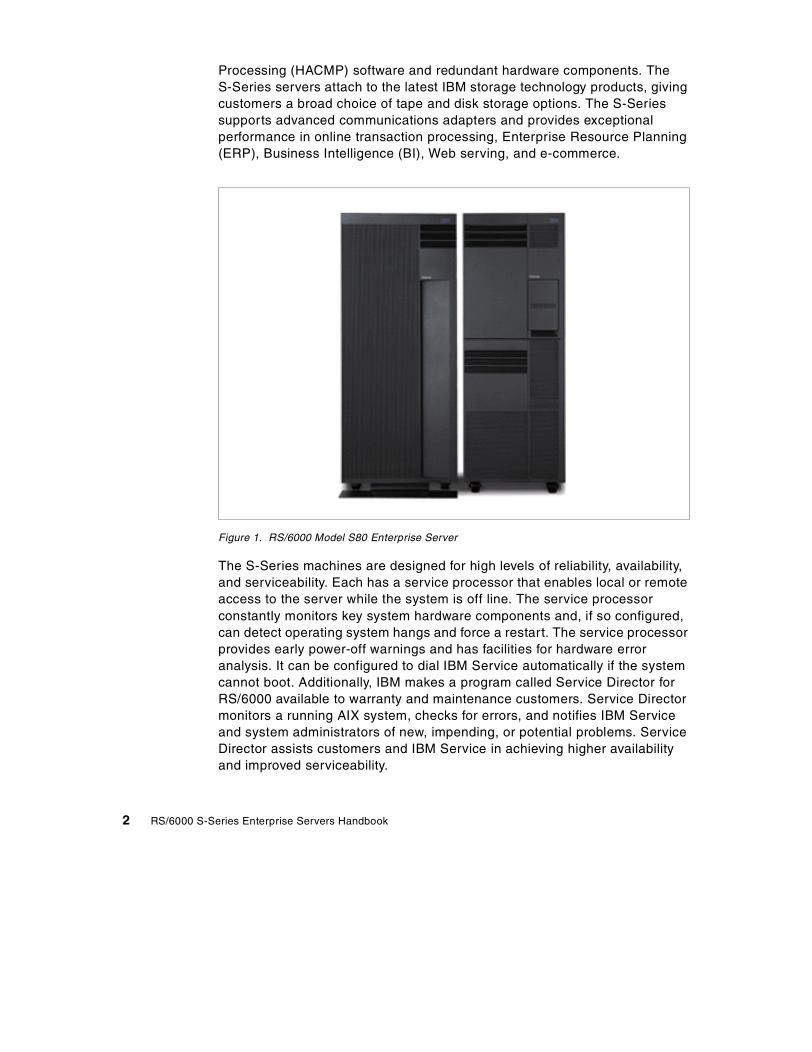
Processing (HACMP) software and redundant hardware components. TheS-Series servers attach to the latest IBM storage technology products, givingcustomers a broad choice of tape and disk storage options. The S-Seriessupports advanced communications adapters and provides exceptionalperformance in online transaction processing, Enterprise Resource Planning(ERP), Business Intelligence (BI), Web serving, and e-commerce.
Figure 1. RS/6000 Model S80 Enterprise Server
The S-Series machines are designed for high levels of reliability, availability,and serviceability. Each has a service processor that enables local or remoteaccess to the server while the system is off line. The service processorconstantly monitors key system hardware components and, if so configured,can detect operating system hangs and force a restart. The service processorprovides early power-off warnings and has facilities for hardware erroranalysis. It can be configured to dial IBM Service automatically if the systemcannot boot. Additionally, IBM makes a program called Service Director forRS/6000 available to warranty and maintenance customers. Service Directormonitors a running AIX system, checks for errors, and notifies IBM Serviceand system administrators of new, impending, or potential problems. ServiceDirector assists customers and IBM Service in achieving higher availabilityand improved serviceability.
2 RS/6000 S-Series Enterprise Servers Handbook

1.1.1 Model S80 specificsThe Model S80 base configuration has a 6-way 450 MHz RS64 III processorcard. Each processor has 8 MB of level 2 (L2) cache. Minimum systemmemory is 2 GB of SDRAM. Cache and system memory is capable ofsingle-bit error correction and double-bit error detection (ECC).
A 6-way system can be expanded to a 12-, 18- or 24-way system, with eachadditional processor card, called a book, containing six processors. Memorycan be increased to 64 GB. Memory must be installed in four-card sets, calledquads, which are available in the following sizes: 1 GB (4 x 256 MB), 2 GB (4x 512 MB), 4 GB (4 x 1024 MB), 8 GB (4 x 2048 MB) and 16 GB (4 x 4096MB). There are 16 memory book slots, allowing a total of four quads to beinstalled. Memory cards must be identical within each quad.
The I/O Rack holds the primary I/O Drawer, which contains:
• Service processor
• High-performance disk drive
• 32X Maximum speed CD-ROM
• 1.44 MB 3.5-inch diskette drive
• Two PCI Ultra SCSI controllers
Up to three additional I/O Drawers can be added. Each drawer provides 14PCI slots across four independent buses. Each drawer may contain two UltraSCSI hot-pluggable disk 6-packs. Existing RS/6000 7015 Model R00 and7014 Model S00 racks can also be used for additional rack-mounted storageand communication devices.
A fully-configured system consists of 24 processors, 64 GB of systemmemory, 53 available PCI adapter slots (the service processor and two UltraSCSI controllers take up three slots in the first I/O Drawer), 48 hot-pluggabledisk bays, and seven available media bays. If the PCI Dual Channel Ultra2SCSI adapter (#6205) is ordered, it can replace two PCI Single-Ended UltraSCSI adapters, bringing the maximum number of available PCI slots on afully-configured system to 54.
PCI adapters may be used to support a wide range of communications andstorage subsystems. Supported communications adapters include GigabitEthernet, 10/100 Mbps Ethernet, Standard Ethernet, Token Ring,Asynchronous Transfer Mode (ATM), and Fiber Distributed Data Interface(FDDI). Supported storage device protocols include Ultra SCSI, Ultra2 SCSI,Serial Storage Architecture (SSA), and Fibre Channel-Arbitrated Loop(FC-AL).
Chapter 1. Overview of the S-Series 3
The Model S80 is shipped and delivered with internal adapters and devicesalready installed and configured. The Model S80 requires AIX Version 4.3.3or later, which comes with every system ordered and, if desired, can bepre-installed.
1.1.2 Model S70 Advanced specificsThe base Model S70 Advanced server configuration features one 4-way 262MHz RS64 II processor book. Each processor has 8 MB of L2 cache. Theminimum system configuration includes 1 GB of SDRAM memory.
Two additional processor books may be added to the CEC of the Model S70Advanced, allowing for 4-, 8- and 12-way configurations. System memory canbe expanded to 32 GB. As with the Model S80, memory must be installed infour card sets called quads. The Model S70 Advanced has 20 memory cardslots allowing a total of five quads. Memory is available in quads of 1 GB (4 x256 MB), 2 GB (4 x 512 MB), 4 GB (4 x1024 MB), and 8 GB (4 x 2048 MB).
The I/O Rack holds the primary I/O Drawer, which contains:
• Service processor
• High-performance disk drive
• 32X Maximum speed CD-ROM
• 1.44 MB, 3.5-inch diskette drive
• Two PCI Ultra SCSI controllers
Three additional I/O Drawers may be added. No more than two I/O Drawersmay reside in a single rack. External disk drawers may be installed in racks asspace permits.
A fully-configured system consists of 12 processors, 32 GB of systemmemory, 53 available PCI adapter slots, 48 hot-pluggable internal disk bays,and seven available media bays. In the primary I/O Drawer, the serviceprocessor uses one slot, and two slots are taken for the SCSI cards thatcontrol the media bays and the first disk six-pack. If the PCI Dual ChannelUltra2 SCSI adapter (#6205) is ordered, it can replace two PCI Single-EndedUltra SCSI adapters, bringing the maximum number of available PCI slots ona fully-configured system to 54.
PCI adapters may be used to support a wide range of communications andstorage subsystems. Supported communications adapters include GigabitEthernet, 10/100 Mbps Ethernet, Standard Ethernet, Token Ring, ATM and
4 RS/6000 S-Series Enterprise Servers Handbook
FDDI. Storage device protocols include Ultra SCSI, Ultra2 SCSI, SSA andFC-AL.
The Model S70 Advanced is shipped and delivered with adapters and devicesalready installed and configured. System power supplies are designed formaximum configurations. The Model S70 Advanced comes with AIX Version4.3. The operating system can be preinstalled, if desired.
1.2 Competitive positioning
The performance, expandability, and reliability of the Model S80 and ModelS70 Advanced make them strong candidates for the most complexmission-critical e-business applications, as well as ERP, BI, serverconsolidation, and OLTP solutions. The Model S80 in particular offersleadership performance that makes it a very attractive choice for largecommercial and e-business workloads.
The Model S80 is the natural growth path for the Models S70 and S70Advanced. It offers more performance, memory, and storage. Afully-configured Model S80 is roughly 3.5 times more powerful than afully-configured Model S70 Advanced.
The S-Series machines are designed from the ground up for mission-criticalenvironments. They come with a service processor, redundant power andcooling, and hot-swap disk drives. You can cluster S-Series models with HighAvailability Cluster Multi-Processing (HACMP) for AIX to achieve even greateravailability and horizontal growth.
The Model S80 has the capacity to meet current and future needs with achoice of 6, 12, 18, or 24 processors and extensive memory options from 2GB up to 64 GB. The Model S70 Advanced offers excellent price performancewith four, eight, or 12 processors and up to 32 GB of memory. Both systemscan be configured with up to 53 available PCI expansion slots and up to 45TB of disk storage.
Competitive systems sold in these application environments include the SunEnterprise 6500 and 10000 servers, the HP V2500, and possibly someclustered Alpha chip systems from Compaq. The Model S80’s leadingperformance and the excellent price/performance characteristics of theS-Series machines make them very strong contenders in the high-endcommercial computing marketplace.
Chapter 1. Overview of the S-Series 5
1.3 Performance benchmarks
In July 1999, IBM released some preliminary performance numbers for thethen-unannounced Model S80. SPECWeb96 and Java VolanoMarkbenchmark results were released. Shortly after availability of the Model S80,benchmark results for online transaction processing were released,confirming that the Model S80 is the performance leader among high-endUNIX servers. Changes made to the system for commercial applications,such as doubling the number of processors, almost doubling the clock rate,improving the cache, and increasing processor bandwidth, have producedmany new benchmark records.
1.3.1 Online transaction processingBased on the TPC-C benchmark, the Model S80 is the world's most powerfulsystem for transaction processing. In addition, Transaction ProcessingPerformance Council results show a single Model S80 system with 24processors can perform more transactions than a cluster of four 24-processorSun E6500 servers (96 microprocessors in total).
The Model S80 is also the best value among large enterprise servers with thelowest cost per transaction among the 10 most powerful systems. The S80performed 135,815 transactions per minute (tpmC) at $52.70 per transaction($/tpmC), which is 50 percent better performance for the dollar than the SunE10000 and 45 percent better than Sun’s cluster result.
For more information on this benchmark result, refer to the TransactionProcessing Performance Council Website at the following URL:
http://www.tpc.org
1.3.2 SPECWeb96A new SPECWeb96 record was set with a 12-way Model S80 using aprerelease version of AIX 4.3.3. The Model S80 delivered a SPECweb96benchmark of 40,161 http operations per second, which is 66 percent betterthan the 24,139 http operations per second posted by the former leader, aneight-way HP 9000/N4000 server from Hewlett-Packard. SPECWeb96measures the maximum number of Hypertext Transfer Protocol (HTTP)operations per second. Fast servers that are reliable and can handle largenumbers of users are considered critical to companies expanding theirbusinesses and their customer relationships onto the Internet.
For more information on the SPECWeb benchmark, refer to the StandardPerformance Evaluation Corporation Website at the following URL:
6 RS/6000 S-Series Enterprise Servers Handbook
http://www.spec.org
1.3.3 Java environment performanceThe Java VolanoMark record was achieved on a six-way Model S80. Ittransferred 22,906 messages per second, which is a 92 percent increase overthe previous top result posted by Hewlett-Packard with an N Class serverconfigured with eight processors. The VolanoMark is designed to accuratelypredict real world Java environment performance and scalability. Thebenchmark creates a large number of active socket connections and threadsand forces the system to constantly switch among them all. This behavior iskey to successfully deploying Java environments for e-business applications.
While hardware improvements were important in setting these new records,AIX enhancements were also very significant. AIX 4.3.3 offers several Javaenvironment, Web-performance, and scalability enhancements.
1.4 AIX Version 4.3 and commercial computing
AIX Version 4.3.3 offers a number of performance and system administrationenhancements for commercial systems.
1.4.1 Kernel scalability enhancementsKernel scalability enhancements have greatly increased OLTP throughput.Because S-Series machines are capable of handling large memoryconfigurations, AIX 4.3.3 supports multiple lists of free memory frames. Aframe is a 4 KB unit of real memory. It maps 1:1 to a 4 KB page of virtualmemory. The latest kernel also supports multiple page replacementdaemons. These constantly-running processes manage real memory bydeciding whether the contents of a location in memory should remain wherethey are or be moved to disk, where it will take more time to retrieve them inthe future. Allowing multiple lists and having multiple daemons reducesmemory contention and latency (the time needed to retrieve data orinstructions needed by a processor).
In another kernel enhancement, runnable threads are assigned to local runqueues on a per-processor basis. This simplifies the dispatcher’s decisionabout which thread to run next by reducing lock contention and eliminatingtime-consuming calculations needed to maintain affinity between a processorand its cached data. The algorithms used by the dispatcher have been tunedto provide better transaction throughput on busy SMP systems. At AIX 4.3.3,user threads generate less cache interference and maintain a greater affinityto a single processor.
Chapter 1. Overview of the S-Series 7
Other AIX 4.3.3 enhancements include:
• The ability to mirror striped logical volumes
• A guarantee that mirrored logical volume copies will exist on different disks
• The ability to do an online backup of a mirrored journaled file system
• The ability to create a system backup image on a Write Once Read Many(WORM) CD drive
• Console messages are logged to a file and time stamped
Faster reboot times may be possible because the system allows some deviceconfiguration methods to run in parallel. This option may produce a fasterreboot when multiple devices, such as SCSI disks, TTYs, and multiportasynchronous adapters, are connected to a system. A serializationmechanism is used when the configuration manager recognizes that newdevices have been added. The system configuration manager still follows thehierarchical device tree, but it can traverse multiple branches at the sametime, as long as nothing has been changed from the previous boot. AIX 4.3.3supports up to 16 concurrent configuration methods.
1.4.2 Workload managementA new facility called workload management comes with AIX 4.3.3. It gives asystems administrator greater control over how the scheduler and VirtualMemory Manager (VMM) determine priorities and allocate system resources.
Although the CPU and memory workload management functions describedhere can be used with any RS/6000 running AIX 4.3.3, it is expected that theywill most commonly be used on large servers running multiple differingworkloads that may sometimes compete with one another.
Workload management can help provide isolation between user communitiesthat make very different demands on the system. Some users are likely to runinteractive or CPU-intensive applications, while others may require batch ormemory-intensive capabilities.
Workload management is fundamentally different from operating systempartitioning, which is also called logical partitioning or LPAR. LPAR has beenimplemented on S/390 and AS/400. Partitioning isolates and dedicateshardware resources to multiple copies of the operating system running on asingle machine. In contrast, the goal of workload management is to makemore efficient and flexible use of CPUs and memory under the control of asingle copy of the operating system.
8 RS/6000 S-Series Enterprise Servers Handbook

A more in-depth discussion of workload management can be found in Section4.2, “Workload management” on page 68.
Chapter 1. Overview of the S-Series 9

10 RS/6000 S-Series Enterprise Servers Handbook
Chapter 2. Detailed descriptions
This chapter takes an in-depth look at the hardware packaging and featuresthat comprise the RS/6000 Model S80 and Model S70 Advanced EnterpriseServers. The standard and optional features of each model are describedalong with the features of the I/O Drawer and I/O Rack that are identical onboth systems.
This chapter also includes some guidelines for using the PCRS6000Configurator to create a valid system order.
2.1 Model S80 description
The Model S80 was announced on September 13th, 1999 and is a member ofa new generation of 64-bit 6-, 12-, 18-, or 24-way symmetric multiprocessing(SMP) enterprise servers. The Model S80 can be used as a stand-aloneserver, but it can also be attached to the RS/6000 SP as an SP-attachedserver. When configured as an SP-attached server, the S80 is managed andcontrolled just like a regular SP node using the SP-unique Parallel SystemSupport Program (PSSP) systems management software.
The Model S80 is packaged as a central electronic complex and an I/O Rack.The Model S80 entry configuration starts with a six-way scalable SMP systemthat utilizes the 64-bit, 450 Mhz, RS64 III processor with 8 MB of Level 2 (L2)cache per processor. The 6-way SMP can be expanded to a 24-way SMP, andthe system memory can be expanded to 64 GB.
The I/O Rack contains the first I/O Drawer with:
• A service processor
• A high-performance disk drive
• 32X maximum speed CD-ROM
• 1.44 MB 3.5-inch diskette drive
• Two PCI SCSI adapters
Up to three additional Model S80 I/O Drawers can be added. Additional I/ORacks can also be ordered with the Model S80. Existing RS/6000 7015 ModelR00 and 7014 Model S00 racks can also be used for additional storage andcommunication drawers. This helps to protect your existing investment in SSAor SCSI DASD.
© Copyright IBM Corp. 1999 11
The RS/6000 Enterprise Server Model S80 is shipped and delivered with allthe internal adapters and devices already installed and configured. AIXVersion 4.3.3 software is included with every Model S80 and can bepreinstalled if desired.
2.1.1 Base configurationA new Model S80 order must include a minimum of the following items:
• One Model S80 system unit, which provides the CEC (Central ElectronicComplex) enclosure, system backplane, and CEC power
• Cabling for connection to the primary I/O Drawer
• Two Remote I/O Cable - CEC to I/O Drawer (#3143 or #3144)
• One system control and initialization cable (#6000)
• Two power control cable, Processor Complex to I/O Rack(SPCN)(#6008)
• One Remote I/O Hub - Dual Loop (#6503)
• One 6-way processor complex
• First RS64 III Processor, 6-Way SMP 450 MHz, 8 MB L2 Cache(#5318)
• 2 GB Memory Minimum - choose from:
• Two 1024 MB R1 Memory (4 x 256 MB Cards) (#4190)
• One 2048 MB R1 Memory (4 x 512 MB Cards) (#4191)
• One 4096 MB R1 Memory (4 x 1024 MB Cards) (#4192)
• One 8192 MB R1 Memory (4 x 2048 MB Cards) (#4193)
• One 16384 MB R1 Memory (4 x 4096 MB Cards) (#4194)
• One I/O Rack (#7000)
• One Primary I/O Drawer including:
• I/O Drawer, 10EIA, AC Power, Unconfigured (#6320)
• Primary I/O Drawer Group (#6321)
• Support Processor Group (#6326)
• 32X (Max) SCSI-2 CD-ROM Drive (#2624)
• 9 GB Hard Disk (Minimum) - choose from:
• One - 9.1 GB Ultra-SCSI 16-bit Hot-Swap Disk Drive (#2913)
• One - 9.1 GB 10,000 RPM Ultra-SCSI Hot-Swap Disk Drive (#3008)
12 RS/6000 S-Series Enterprise Servers Handbook

• One - 18.1 GB Ultra-SCSI 16-bit Hot-Swap Disk Drive (#3104)
• SCSI Backplanes, Adapters, and Cables. Choose either Single or DualBackplane Solution.
• Single Backplane solution, consisting of:
• One - SCSI 6-Pack Hot-Swap Backplane/Power Cable (#6547)
• Two - PCI Single-Ended Ultra SCSI Adapter (#6206)
• One - SCSI-2 Backplane-to-DASD 6-Pack Cable (#2447)
• Dual Backplane solution, consisting of:
• Two - SCSI 6-Pack Hot-Swap Backplane/Power Cable (#6547)
• Three - PCI Single-Ended Ultra SCSI Adapter (#6206)
• Two - SCSI-2 Backplane-to-DASD 6-Pack Cable (#2447)
In either solution, two of the PCI Single-Ended Ultra SCSI Adapters maybe replaced by a single PCI Dual Channel Ultra2 SCSI Adapter (#6205).However, the Ultra2 adapter will function at Ultra SCSI speed.
2.1.2 ProcessorEach Model S80 processor card has six RS64 III processors with theassociated L2 cache contained on the card. There are 8 MB of L2 perprocessor. Each processor card has the six processors on a set of two SMPsystem buses and that dual bus interface is presented to the S80 backplane.All the processor cards in a system need to use the same type and speed ofprocessor. The Model S80 can accommodate 4 CPU cards. The first CPUcard is a Type 1 card (#5318) and is included in a base configuration. Up tothree additional Type 2 cards (#5319) may be added.
• (#5318) 450 Mhz Card with 8 MB L2 Cache, First
• (#5319) 450 Mhz Card with 8 MB L2 Cache, Additional
2.1.3 PowerThe Model S80 comes equipped with sufficient power supplies for a 6- or12-way system. When ordering a 12- or 24-way system, an additional powersupply, processor regulator, and power regulator must be ordered:
• (#6913) 1000 Watt AC Power Supply
• (#6914) Programmable Power Regulator
• (#6915) Processor Power Regulator
Chapter 2. Detailed descriptions 13

These additional power components are all installed in the front of the ModelS80 CEC. The 1000 Watt AC Power Supply is installed in position P05; theProgrammable Power Regulator is installed in position R08, and theProcessor Power Regulator is installed in position M07. The locations areshown in Figure 2 on page 15.
2.1.4 MemoryThe Model S80 base configuration includes 2 GB of SDRAM-based memory.The maximum configuration is 64 GB. The Model S80 can accommodate upto 16 memory cards. Memory cards are used in sets of four, called quads.The memory subsystem provides ECC for single bit error correction anddouble bit error detection.
The Model S80 SDRAM memory cards contain redundant modules thatsupport up to one in 14 memory modules not working. The memory isscrubbed by the controller, a feature that is designed to eliminate soft errorproblems. Memory cards are available in 512 MB, 1 GB, 2 GB and 4 GBsizes. SDRAM modules are directly and permanently attached to the memorycards, a feature that minimizes failures and faults caused by connectors orsockets. A Model S80 must have a minimum of 2 GB of memory.
System memory is accessed through four related but distinct ports. A systemshould be configured with a minimum of two memory quads to make best useof the system architecture. Multiple ports can be accessed in a coordinatedparallel manner and can obtain more data in the same amount of time. Aconfiguration that uses only one port will function properly, but the system cannot make use of the full memory bus bandwidth. For example, a system with 2GB of memory will perform better with two 1 GB features installed than if one2 GB feature is installed.
The available memory features are as follows:
• (#4190) 1024 MB Memory (4 x 256 MB Cards)
• (#4191) 2048 MB Memory (4 x 512 MB Cards)
• (#4192) 4096 MB Memory (4 x 1024 MB Cards)
• (#4193) 8192 MB Memory (4 x 2048 MB Cards)
• (#4194) 16384 MB Memory (4 x 4096 MB Cards)
The physical layout of the front of Model S80 CEC is shown in Figure 2 onpage 15.
14 RS/6000 S-Series Enterprise Servers Handbook

Figure 2. Front view of Model S80 CEC
The memory quads on the system are referred to as A, B, C, and D. Threememory cards, each from quads A and B, are installed on the front of thesystem. The remaining single card from each quad is installed in the rear ofthe system. Figure 3 on page 16 shows the rear of the Model S80 CEC. Allfour cards of each of the C and D quads are installed in the rear of thesystem.
B M08
B M09
B M10
PROC CARD 2 M06
PROC REG M07
A M01
A M02
A M03
BASE PROC REG M04
PROC CARD 0 M05
18-24Procs
R01 R08R07R06R05R04R03R02 R09 R10
18-24Procs
PROG REG
PROG REG
PROG REG
PROG REG
MEM REG
PROG BASE
PROG REG
PROG REG
PROG REG
PROG REG
Memory MemoryRegulators
Base Base Base Base
P01 P05P04P03P02BulkFiller
18-24Procs
BULK POWER SUPPLIES
BLOWER 1B01
BLOWER 2B02
Chapter 2. Detailed descriptions 15

Figure 3. Rear view of Model S80 CEC
2.1.5 Disk drivesDisk drives are available for installation in the I/O Drawers of the Model S80.Disk drives are not supported in the media section of the I/O Drawers. EachI/O Drawer supports up to two SCSI 6-packs. As the name suggests, each6-pack supports up to six hot-pluggable 16-bit SCSI disk drives. All diskdrives must be 16-bit devices. Each 6-pack must be connected to an SCSIadapter using a 6-pack attachment cable.
Disk Drives:
C M12
C M13
R21
SPCN CARD
Regulators
AC Box A01
BLOWER 3B03
BLOWER 4B04
C M14
C M15
M17
D M20
D M21
D M22
D M23
Memory
A M24
B M11
PROC CARD 3 M16
RIO PORTS
I/O HUB CARD
PROC CARD 1 M18
JTAG PORT
CLOCK/PROC REG
M19
Memory
16 RS/6000 S-Series Enterprise Servers Handbook

• (#2913) 9.1 GB 1" Ultra SCSI Hot-Swap
• (#3008) 9.1 GB 10,000 RPM Ultra SCSI Hot-Swap
• (#3104) 18.2 GB Ultra SCSI 1" Hot-Swap
SCSI 6-pack:
• (#6547) SCSI 6-pack
6-pack Attachment Cables:
• (#2447) Attachment to PCI SCSI/RAID Adapter
2.1.6 SCSI adaptersBoot support is available from local SCSI Adapters (Ultra SCSI Single-endedAdapter, Differential Ultra SCSI Adapter, Dual Channel Ultra2 SCSI Adapter).
The recommended location for the boot device (SCSI) is within the base I/ODrawer. This configuration provides service personnel with the maximumamount of diagnostic information if the system encounters errors in the bootsequence. The default boot drive is in the lowest location in the six-pack, inthe inner-most bay of the I/O Drawer. Manufacturing installs the boot adapterin slot 13. If a boot source other than internal disk is configured, thesupporting adapter must also be in the first I/O Drawer.
SCSI Adapters:
• (#6205) Dual Channel Ultra2 SCSI Adapter
• (#6206) Ultra SCSI Single-Ended Adapter
• (#6207) Ultra SCSI Differential Adapter
The base configuration of the Model S80 comes with two Ultra SCSISingle-Ended Adapters (#6206). One adapter drives the media bays, and theother drives the first SCSI 6-pack. These two adapter cards can be replacedby a single Dual Channel Ultra2 SCSI Adapter (#6205), which increases thenumber of available PCI slots in the primary I/O Drawer. However, the Ultra2adapter will operate at Ultra speed.
2.1.7 I/O DrawersSee Section 2.3.2, “I/O Drawer description” on page 36, for a full descriptionof the Model S80 I/O Drawer. The original 7 EIA Model S70 I/O Drawers arenot supported on the S80.
Chapter 2. Detailed descriptions 17

The standard peripherals required in the minimum configuration include thefollowing:
• 1.44 MB Diskette Drive
• (#2624) 32X Speed CD-ROM
The following feature code is the base I/O Drawer:
• (#6320) Base SCSI I/O Drawer, 10 EIA
The following lists the feature codes of the drawer groups:
• (#6321) Primary I/O Drawer Group
• (#6323) Secondary I/O Drawer Group
2.1.8 CablingThe CEC and the I/O Drawers are connected by various cables. The primaryI/O Drawer has additional connections.
2.1.8.1 System Power Control NetworkSee Section 2.3.3, “Serial Power Control Network (SPCN)” on page 38, for afull description of the purpose and configuration options for SPCN cables.
The available SPCN cables for Model S80 systems are as follows:
• (#6006) 2-meter drawer-to-drawer control cable
• (#6007) 15-meter rack-to-rack control cable
• (#6008) 6-meter rack-to-rack control cable
2.1.8.2 Remote I/O cablesSee Section 2.3.4, “Remote I/O cabling” on page 40, for a full description ofthe purpose and configuration options for Remote I/O cables.
RIO cables are available in three different lengths. The 3-meter cables canonly be used to interconnect two I/O Drawers in the same rack. Manufacturingwill determine the placement and cabling of I/O Drawers based on thequantity of I/O Racks and RIO cables ordered.
The following remote I/O cables are available on Model S80 systems:
• (#3142) 3-meter drawer-to-drawer remote I/O cable
• (#3143) 6-meter rack-to-rack remote I/O cable
• (#3144) 15-meter rack-to-rack remote I/O cable
18 RS/6000 S-Series Enterprise Servers Handbook

2.1.9 Model S80 configurationsTable 1 lists the S80 standard configuration.
Table 1. Model S80 standard configuration
Table 2 lists the S80 system expansion capabilities.
Table 2. Model S80 system expansion
Model S80 Standard Configuration and Features
Microprocessor One 6-way 450 MHz RS64 III CPU card
Level 1 (L1) cache 128 KB data/128 KB instruction
Level 2 (L2) cache 8 MB per processor
RAM (minimum) 2 GB
Memory bus width Quad 512-bit
Ports One parallel, two serial, one keyboard,and one mouse
Internal disk drive One 9.1 GB Ultra SCSI (hot-swappable)
Media bays Two (one available)
Expansion slots Fourteen PCI (eleven available)
PCI bus width 32- and 64-bit
Memory slots 16
CD-ROM drive 32X (max)
Service processor Yes
Diskette drive 1.44 MB 3.5-inch diskette drive
SCSI adapters Two Ultra SCSI PCI adapters
AIX operating system version Version 4.3 (A one- to two-user serverlicense is included)
Model S80 Maximum Configuration
SMP configurations Up to three additional 6-way processorbooks
RAM Up to 64 GB
Internal PCI slots Up to 56 per system (53 available)
Internal media bays Up to eight per system (seven available)
Chapter 2. Detailed descriptions 19
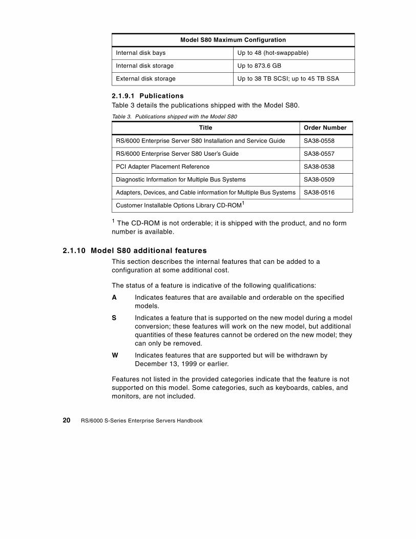
2.1.9.1 PublicationsTable 3 details the publications shipped with the Model S80.
Table 3. Publications shipped with the Model S80
1 The CD-ROM is not orderable; it is shipped with the product, and no formnumber is available.
2.1.10 Model S80 additional featuresThis section describes the internal features that can be added to aconfiguration at some additional cost.
The status of a feature is indicative of the following qualifications:
A Indicates features that are available and orderable on the specifiedmodels.
S Indicates a feature that is supported on the new model during a modelconversion; these features will work on the new model, but additionalquantities of these features cannot be ordered on the new model; theycan only be removed.
W Indicates features that are supported but will be withdrawn byDecember 13, 1999 or earlier.
Features not listed in the provided categories indicate that the feature is notsupported on this model. Some categories, such as keyboards, cables, andmonitors, are not included.
Internal disk bays Up to 48 (hot-swappable)
Internal disk storage Up to 873.6 GB
External disk storage Up to 38 TB SCSI; up to 45 TB SSA
Title Order Number
RS/6000 Enterprise Server S80 Installation and Service Guide SA38-0558
RS/6000 Enterprise Server S80 User’s Guide SA38-0557
PCI Adapter Placement Reference SA38-0538
Diagnostic Information for Multiple Bus Systems SA38-0509
Adapters, Devices, and Cable information for Multiple Bus Systems SA38-0516
Customer Installable Options Library CD-ROM1
Model S80 Maximum Configuration
20 RS/6000 S-Series Enterprise Servers Handbook

Table 4 lists Model S80 optional features and their status.
Table 4. Model S80 optional features
Feature Code Description Status
Processors
5318 RS64 III 6-way 450MHz first A
5319 RS64 III 6-way 450MHz additional A
Memory
4190 1024 MB (4x256) A
4191 2048 MB (4x512) A
4192 4096 MB (4x1024) A
4193 8192 MB (4x2048) A
4194 16384 MB (4x4096) A
Host Attachment
2751 ESCON Control Unit A
8396 SP Attach Adapter A
Internal Disk Drives
2901/9394 4.5 GB Ultra SCSI Hot-Swap W
2911/3019 9.1 GB Ultra SCSI Hot-Swap S
2913 9.1 GB 1" Ultra SCSI Hot-Swap A
3104 18.2 GB 1" Ultra SCSI Hot-Swap A
3008 9.1 GB 10K RPM Ultra SCSI Hot-Swap A
Internal Tape Drives
6142 4/8 GB 4 mm W
6147 5/10 GB 8 mm W
6154 20/40GB 8 mm (White) S
6156 20/40 GB 8 mm (Black) A
6159 12/24 GB 4 mm A
Internal CD-ROMs
Chapter 2. Detailed descriptions 21

2619 20X Speed CD-ROM S
2624 32X Speed CD-ROM A
Graphics Accelerators
2838 GXT120P W
2830 GXT130P A
SCSI Adapters
6206 Ultra SCSI SE A
6207 Ultra SCSI Differential A
6208 SCSI 2 Fast / Wide S
6205 Dual Channel Ultra2 SCSI A
SSA Adapters
6215 SSA Multi-Initiator / RAID EL W
6222 SSA Fast-Write Cache Option W
6225 IBM Advanced Serial RAID A
6235 IBM Advanced Serial RAID Cache Option A
Async Adapters
2943 8-Port Async EIA-232/422 A
2944 128-Port Async Controller A
ARTIC Adapters
2947 ARTIC960Hx 4-Port Selectable A
2948 ARTIC960Hx 4-Port T1/E1 PCI W
Digital Trunk Adapters
6310 ARTIC960RxD Quad Digital A
Cryptographic Adapters
4758-001 Cryptographic Coprocessor (PCI) S
ATM Adapters
2963 Turboways 155 PCI UTP ATM A
Feature Code Description Status
22 RS/6000 S-Series Enterprise Servers Handbook

1 See Section 2.5.2, “Configuring S-Series servers” on page 48.
2.2 Model S70 Advanced description
The S70 Advanced was announced on October 23rd, 1998 and is anenhanced version of the Model S70. The S70 Advanced can be used as astand-alone server, but it can also be attached to the RS/6000 SP as anSP-attached server. Using a specially-designed adapter (separately
2988 Turboways 155 PCI MMF ATM A
Token-Ring Adapters
2920 Token-Ring Adapter W
2979 Auto LANStreamer Token-Ring S
4959 Token-Ring PCI Adapter A
Ethernet Adapters
2968 IBM 10/100 Mbps Ethernet A
2969 Gigabit SX A
2985 Ethernet BNC / RJ-45 A
2986 Fast Etherlink XL 3Com S
2987 Ethernet AUI / RJ-45 A
WAN Adapters
2962 2-Port Multiprotocol PCI A
Fiber Channel Adapters
6227 Gigabit Fibre Channel Adapter1 A
FDDI Adapters
2741 SysKonnect SK-NET FDDI-LP SAS A
2742 SysKonnect SK-NET FDDI-LP DAS A
2743 SysKonnect SK-NET FDDI-UP SAS A
ISDN Adapter
2708 Eicon ISDN DIVA PRO 2.0 PCI S/T A
Feature Code Description Status
Chapter 2. Detailed descriptions 23

available) that fits within the S70 Advanced I/O Drawer, the system is capableof connecting directly into the SP Switch fabric. The system is then ideallysuited to handle large database transactions while allowing the other SPnodes to act as application servers. When configured as an SP-attachedserver, the S70 Advanced is managed and controlled just like a regular SPnode using the SP-unique Parallel Systems Support Programs (PSSP)systems management software.
The RS/6000 Enterprise Server S70 Advanced is shipped and delivered withall the internal adapters and devices already installed and configured. AIXVersion 4.3 software is included with every S70 Advanced and may bepreinstalled, if desired.
2.2.1 ProcessorThe RS/6000 Model S70 Advanced server base configuration features one4-way 262 MHz RS64 II book, and it can accommodate up to two additional4-way processor books. The processors include an L1 Cache split into a 64KB instruction cache and a 64 KB data cache. There is 8 MB of ECC L2cache for each 262 MHz processor. The following lists the available processorcards:
• (#5313) 262 MHz Card with 8 MB L2 Cache, Left
• (#5312) 262 MHz Card with 8 MB L2 Cache, Right
2.2.2 PowerThe Model S70 Advanced base configuration is equipped with sufficientpower supplies and regulators. You do not need to order additionalcomponents when ordering a fully-configured system.
2.2.3 MemoryThe base configuration includes 1 GB of SDRAM-based memory consistingof two 512 MB features. The maximum configuration is 32 GB. Memory sizescannot be mixed within each four-card set. There is a maximum of 20 memorycard slots, which means a maximum of five memory quads.
System memory is accessed through two related but distinct ports. Balancedaccesses use both ports in a coordinated parallel manner and can obtain upto twice the data in the same amount of time. Unbalanced configurationsfunction properly, but the memory is only accessed through one port anddoes not make use of the full memory bus bandwidth. For example, a systemwith 2 GB of memory will perform better with two 1 GB features installed thanif one 2 GB feature is installed.
24 RS/6000 S-Series Enterprise Servers Handbook

The following is a list of the available memory features:
• (#4171) 512 MB memory (4x128 MB cards)
• (#4173) 1024 MB memory (4x256 MB cards)
• (#4175) 2048 MB memory (4x512 MB cards)
• (#4177) 4096 MB memory (4x1024 MB cards)
• (#4179) 8192 MB memory (4x2048 MB cards)
The quads on a Model S70 Advanced are referred to as A, B, C, D, and E.The A, B, and C quads are installed on the front of the system CEC. Eachquad has two cards on the left side of the system and two cards on the right.A diagram of the CEC front layout is shown in Figure 4 on page 26.
Chapter 2. Detailed descriptions 25

Figure 4. Front view of Model S70 Advanced CEC
The memory cards of the D and E quads are installed in the rear of thesystem CEC. This is shown in Figure 5 on page 27.
A M14
A M15
TYPE 2 CARD M09
A M01
A M02
A M03
R01 R08R07R06R05R04R03R02 R09 R10
FILLER
PROG*
FILLER
PROG*
PROG*
FILLER
PROG*
FILLER
FILLER
PROG*
Main Storage Main StorageRegulators
P01 P05P04P03P02
BULK POWER SUPPLIES
BLOWER 1B01
BLOWER 2B02
C M06
CLOCK CARD M07
B M04
B M03
C M05
B M12
B M13
C M10
C M11
TYPE 1 CARD M08
ProcessorCards
Slot
Slot
0 OperatorPanelConnector
P06
26 RS/6000 S-Series Enterprise Servers Handbook

Figure 5. Rear view of Model S70 Advanced CEC
As with the A, B, and C quads, two cards from each quad are mounted on theleft side of the CEC, and two cards are mounted on the right side.
2.2.4 Disk drivesDisk drives are not supported in the media section of the I/O Drawers. All diskdrives must be 16-bit devices. Note that the (#2901) 4.5 GB Ultra SCSIFast/Wide feature will be withdrawn as of December 13th 1999.
• (#3104) 18.2 GB 1" Ultra SCSI Hot-Swap
• (#3008) 9.1 GB 10K RPM Ultra SCSI Hot-Swap
D M16
D M17
R21
SPCN CARD
Main StorageRegulators
AC Box or DC BoxA01
BLOWER 3B03
BLOWER 4B04
E M18
E M19
TYPE 1 CARD M20
E M21
E M22
D M23
D M24
ProcessorCard
Main Storage
JTAGConnector
0
0
0
0
0RIO Connector 3
RIO Connector 2
RIO Connector 1
RIO Connector 0
Slot
R21
MEM
R21
MEM
R21
PROG
R21
PROG
R21
PROG
R21
PROG
R21
FILLER
R21
PROG
R21
PROG
0 0 0 0
J14 = UPS Connector
J11 = Remote EPO Connector
J15 = SPCN 0 Connector
J16 = SPCN 1 Connector
Slot
Chapter 2. Detailed descriptions 27

• (#2913) 9.1 GB 1" Ultra SCSI Hot-Swap
• (#2901) 4.5 GB Ultra SCSI Fast/Wide
SCSI 6-pack:
• (#6547) SCSI 6-pack
6-pack Attachment Cables:
• (#2447) Attachment to PCI SCSI Adapter
2.2.5 SCSI adaptersBoot support is available from local SCSI Adapters (Ultra SCSI Single-endedAdapter, PCI SCSI-2 Fast/Wide Differential Adapter, PCI Differential UltraSCSI Adapter, and Dual Channel Ultra2 SCSI Adapter).
The recommended location for the boot device (SCSI) is within the base I/ODrawer. This configuration provides service personnel the maximum amountof diagnostic information if the system encounters errors in the bootsequence. The default boot drive is in the lowest location in the six-pack, inthe inner-most bay of the I/O Drawer. Manufacturing installs the boot adapterin slot 13. If a boot source other than internal disk is configured, thesupporting adapter must also be in the first I/O Drawer.
• (#6205) Dual Channel Ultra2 SCSI Adapter
• (#6206) Ultra SCSI Adapter
• (#6207) Ultra SCSI Differential Adapter
2.2.6 CablingThe CEC and the I/O Drawers are connected by various cables. The primaryI/O Drawer has additional connections.
2.2.6.1 System Power Control Network (SPCN)See Section 2.3.3, “Serial Power Control Network (SPCN)” on page 38, for afull description of the purpose and configuration options for SPCN cables.The base configuration includes two SPCN cables for connecting the primaryI/O Drawer. Additional I/O Drawers must be cabled using the 15-meterrack-to-rack cable or the 2-meter cable, which can only be used tointerconnect two I/O Drawers in the same rack.
The available SPCN cables for Model S70 Advanced systems are as follows:
• (#6006) 2-meter Drawer-to-Drawer Control Cable
28 RS/6000 S-Series Enterprise Servers Handbook
• (#6007) 15-meter Rack-to-Rack Control Cable
2.2.6.2 Remote I/O cablesSee Section 2.3.4, “Remote I/O cabling” on page 40, for a full description ofthe purpose and configuration options for Remote I/O cables.
RIO cables are available in two different lengths. The base system orderincludes two 6-meter cables for connecting the primary I/O Drawer. AdditionalI/O Drawers must be cabled using the 15-meter rack-to-rack cable or the2-meter cable, which can only be used to interconnect two I/O Drawers in thesame rack. Manufacturing will determine the placement and cabling of I/ODrawers based on the quantity of I/O Racks and RIO cables ordered.
The following remote I/O cables are available as additional features on ModelS70 Advanced systems:
• (#3126) 2-meter Remote I/O Cable, Drawer-to-Drawer
• (#3127) 15-meter Remote I/O Cable, Rack-to-Rack
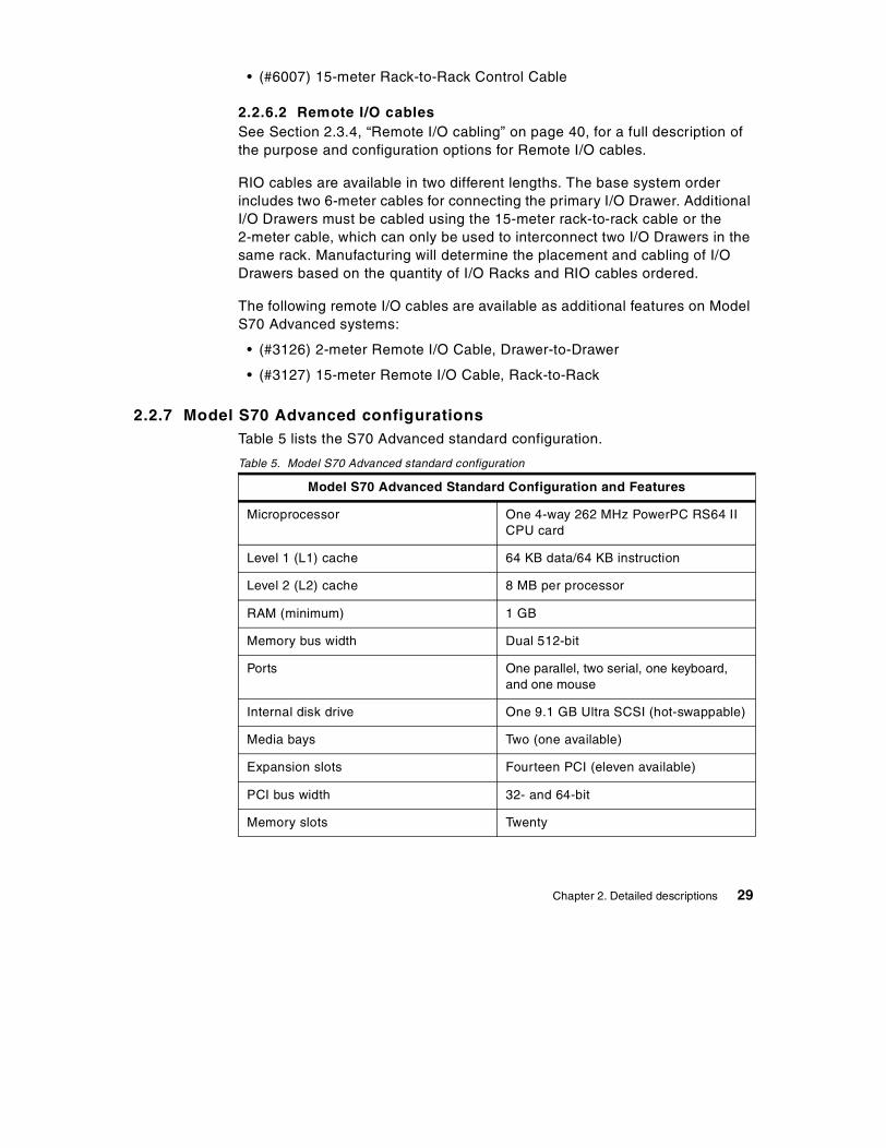
2.2.7 Model S70 Advanced configurationsTable 5 lists the S70 Advanced standard configuration.
Table 5. Model S70 Advanced standard configuration
Model S70 Advanced Standard Configuration and Features
Microprocessor One 4-way 262 MHz PowerPC RS64 IICPU card
Level 1 (L1) cache 64 KB data/64 KB instruction
Level 2 (L2) cache 8 MB per processor
RAM (minimum) 1 GB
Memory bus width Dual 512-bit
Ports One parallel, two serial, one keyboard,and one mouse
Internal disk drive One 9.1 GB Ultra SCSI (hot-swappable)
Media bays Two (one available)
Expansion slots Fourteen PCI (eleven available)
PCI bus width 32- and 64-bit
Memory slots Twenty
Chapter 2. Detailed descriptions 29

Table 6 lists the S70 Advanced system expansion capabilities.
Table 6. Model S70 Advanced system expansion
2.2.7.1 PublicationsTable 7 provides details of the publications shipped with the Model S70Advanced.
Table 7. Publications shipped with the Model S70 Advanced
CD-ROM Drive 32X (max)
Service Processor Yes
Diskette Drive 1.44 MB 3.5-inch diskette drive
SCSI Adapters Two Ultra SCSI PCI Adapters
AIX operating system version Version 4.3 (one to two user serverlicense is included)
Model S70 Advanced Maximum Configuration
SMP configurations Up to two additional 4-way processorbooks
RAM Up to 32 GB
Internal PCI slots Up to 56 per system (53 available)
Internal media bays Up to eight per system
Internal disk bays Up to 48 (hot-swappable)
Internal disk storage Up to 436.8 GB
External disk storage Up to 38 TB SCSI; up to 45 TB SSA
Title Order Number
RS/6000 Enterprise Server S70 Advanced Installation and ServiceGuide
SA38-0548
RS/6000 Enterprise Server S70 Advanced User’sGuide
SA38-0549
Model S70 Advanced Standard Configuration and Features
There is no tape drive supplied in the standard configuration. Customersare able to select their preferred tape drive type as an additional feature.
Note
30 RS/6000 S-Series Enterprise Servers Handbook
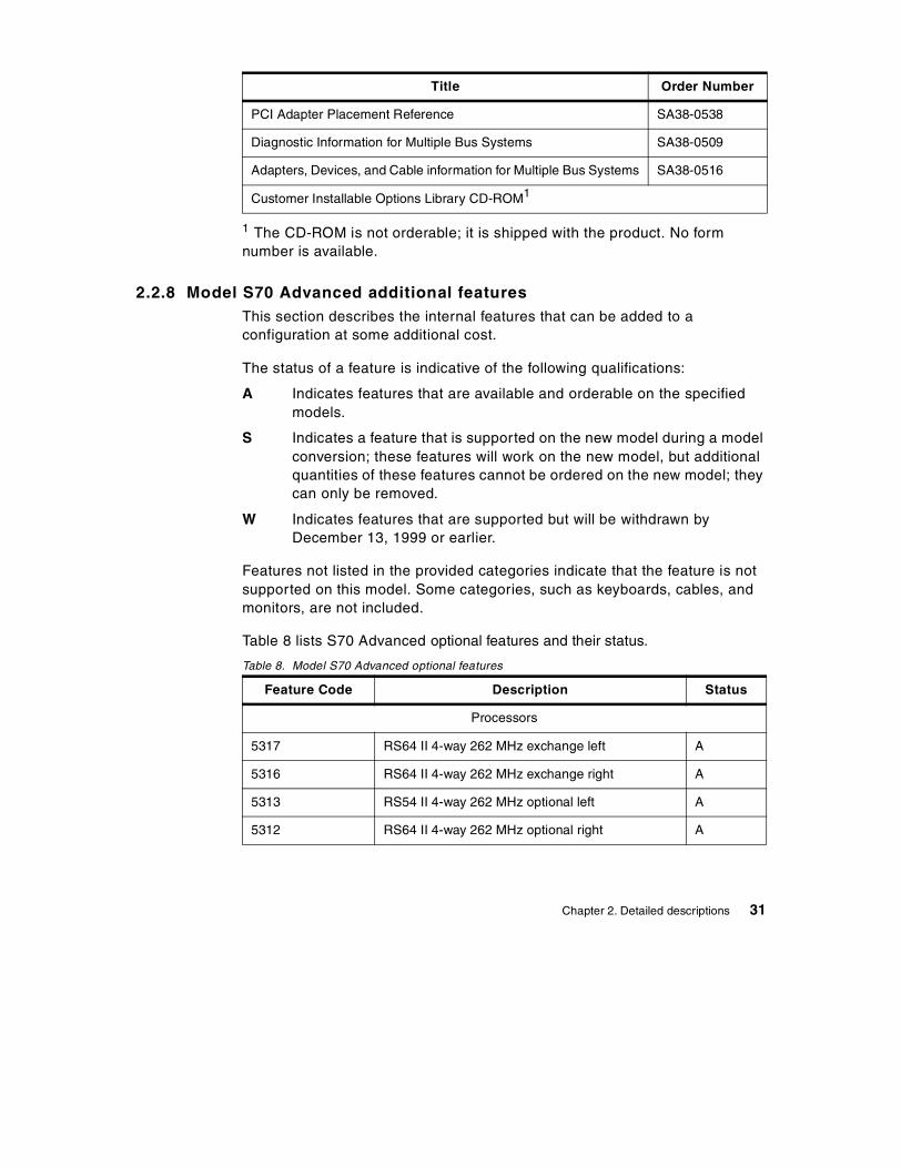
1 The CD-ROM is not orderable; it is shipped with the product. No formnumber is available.
2.2.8 Model S70 Advanced additional featuresThis section describes the internal features that can be added to aconfiguration at some additional cost.
The status of a feature is indicative of the following qualifications:
A Indicates features that are available and orderable on the specifiedmodels.
S Indicates a feature that is supported on the new model during a modelconversion; these features will work on the new model, but additionalquantities of these features cannot be ordered on the new model; theycan only be removed.
W Indicates features that are supported but will be withdrawn byDecember 13, 1999 or earlier.
Features not listed in the provided categories indicate that the feature is notsupported on this model. Some categories, such as keyboards, cables, andmonitors, are not included.
Table 8 lists S70 Advanced optional features and their status.
Table 8. Model S70 Advanced optional features
PCI Adapter Placement Reference SA38-0538
Diagnostic Information for Multiple Bus Systems SA38-0509
Adapters, Devices, and Cable information for Multiple Bus Systems SA38-0516
Customer Installable Options Library CD-ROM1
Feature Code Description Status
Processors
5317 RS64 II 4-way 262 MHz exchange left A
5316 RS64 II 4-way 262 MHz exchange right A
5313 RS54 II 4-way 262 MHz optional left A
5312 RS64 II 4-way 262 MHz optional right A
Title Order Number
Chapter 2. Detailed descriptions 31

Memory
4171 512 MB (4x128) A
9168 Base 512 MB (4x128) S
4173 1024 MB (4x256) A
4174 1024 MB (4x256) select S
4175 2048 MB (4x512) A
4176 2048 MB (4x512) select S
4177 4096 MB (4x1024) A
4178 4096 MB (4x1024) select S
4179 8192 MB (4x2048) A
4180 8192 MB (4x2048) select S
Host Attachment
2751 ESCON Control Unit A
8396 SP Attach Adapter A
Internal Disk Drives
2901/9394 4.5 GB Ultra SCSI Hot-Swap W
2911/3019 9.1 GB Ultra SCSI Hot-Swap S
2913 9.1 GB 1" Ultra SCSI Hot-Swap A
3104 18.2 GB 1" Ultra SCSI Hot-Swap A
3008 9.1 GB 10K RPM Ultra SCSI Hot-Swap A
Internal Tape Drives
6142 4/8 GB 4 mm W
6147 5/10 GB 8 mm S
6154 20/40GB 8 mm (White) S
6156 20/40 GB 8 mm (Black) A
6159 12/24 GB 4 mm A
6160 9-Track 1/2" Tape Drawer W
Feature Code Description Status
32 RS/6000 S-Series Enterprise Servers Handbook

Internal CD-ROMs
2619 20X Speed CD-ROM S
2624 32X Speed CD-ROM A
Graphics Accelerators
2838 GXT120P W
2830 GXT130P A
SCSI Adapters
6206 Ultra SCSI SE A
6207 Ultra SCSI Differential A
6208 SCSI 2 Fast / Wide S
6209 SCSI 2 Fast / Wide Differential S
2493 SCSI 2 Fast / Wide RAID S
6205 Dual Channel Ultra2 SCSI A
SSA Adapters
6215 SSA Multi-Initiator / RAID EL W
6222 SSA Fast-Write Cache Option W
6225 IBM Advanced Serial RAID A
6235 IBM Advanced Serial RAID Cache Option A
Async Adapters
2943 8-Port Async EIA-232/422 A
2944 128-Port Async Controller A
ARTIC Adapters
2947 ARTIC960Hx 4-Port Selectable A
2948 ARTIC960Hx 4-Port T1/E1 PCI W
Digital Trunk Adapters
6310 ARTIC960RxD Quad Digital A
Cryptographic Adapters
Feature Code Description Status
Chapter 2. Detailed descriptions 33
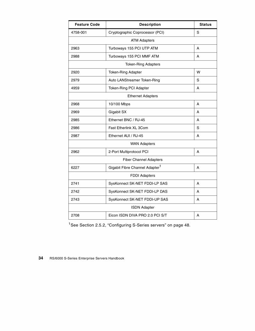
1See Section 2.5.2, “Configuring S-Series servers” on page 48.
4758-001 Cryptographic Coprocessor (PCI) S
ATM Adapters
2963 Turboways 155 PCI UTP ATM A
2988 Turboways 155 PCI MMF ATM A
Token-Ring Adapters
2920 Token-Ring Adapter W
2979 Auto LANStreamer Token-Ring S
4959 Token-Ring PCI Adapter A
Ethernet Adapters
2968 10/100 Mbps A
2969 Gigabit SX A
2985 Ethernet BNC / RJ-45 A
2986 Fast Etherlink XL 3Com S
2987 Ethernet AUI / RJ-45 A
WAN Adapters
2962 2-Port Multiprotocol PCI A
Fiber Channel Adapters
6227 Gigabit Fibre Channel Adapter1 A
FDDI Adapters
2741 SysKonnect SK-NET FDDI-LP SAS A
2742 SysKonnect SK-NET FDDI-LP DAS A
2743 SysKonnect SK-NET FDDI-UP SAS A
ISDN Adapter
2708 Eicon ISDN DIVA PRO 2.0 PCI S/T A
Feature Code Description Status
34 RS/6000 S-Series Enterprise Servers Handbook

2.3 Remote I/O Subsystem description
The I/O subsystem on both the Model S80 and Model S70 Advanced consistsof up to four I/O Drawers housed in I/O Racks and connected to the systemCEC. Each I/O Rack can be configured with up to two I/O Drawers.
2.3.1 I/O Rack descriptionThe I/O Rack supplied as a feature of an S-Series server is the 7014-S00rack. It has 32 EIA units of space and is available with three PowerDistribution Unit (PDU) options. They are selected with the following basefeature codes:
• (#9171) Side-Mounted, 1-Phase
• (#9173) Side-Mounted, 3-Phase
• (#9174) Side-Mounted, 3-Phase, Swiss
Each PDU provides six power outlets. An optional additional PDU can beconfigured in a rack providing the option to power additional equipment orproviding a degree of high-availability to devices that have multiple redundantpower supplies, such as the 7133-D40 SSA enclosure. The following are thefeature codes of available additional Power Distribution Units:
• (#6171) Side-Mounted, 1-Phase
• (#6173) Side-Mounted, 3-Phase
• (#6174) Side-Mounted, 3-Phase, Swiss
The following rules have to be followed for a valid configuration:
• A maximum of four I/O Racks can be ordered as features (#7000) persystem order. I/O Drawers should be spread between I/O Racks but notexceed two per rack.
• I/O Racks ordered as feature numbers of the Model S70 Advanced orModel S80 (#7000) must contain an I/O Drawer. If additional externalcommunication and storage devices, such as 7133 and 7027, do not fit inthe space remaining in the I/O Racks, additional empty I/O Racks shouldbe ordered. The additional I/O Racks should be ordered as products(7014-S00 or 7015-R00) rather than features of the S-Series server. Thereis no limit to the quantity of 7014-S00 and 7015-R00.
• If the quantity of power distribution units (#6171 or #6173) is greater thanone, the space available in the rack is reduced by one EIA.
• The 3570-B11 and 3570-B12 can only be installed in a specific location inthe I/O Rack due to drawer interference. Ordering a machine with rack
Chapter 2. Detailed descriptions 35

contents specify feature code #0166 or #0167 will have the base SCSI I/ODrawer installed in a lower location in the rack leaving a nine EIA spaceempty at the top of the rack. The 3570 is field installed.
• The 3570-C11 and C12 can be installed in any location within the I/ORack.
• Many 3490 and 3590 tape libraries cannot be installed in S-Series servers’I/O Racks due to interference with the rack door. These machine types aresupported for attachment to the S-Series servers, but they must be in aseparate rack (7015-R00) unless the I/O Rack door is removed.Instructions for proper removal of the rack door are included in the tapelibrary installation instructions.
• Two IBM 3590-B11 or 3590-E11 tape drives may share a twelve EIA spacein the rack. (Order one placement for each pair of units.)
• The 3490 Model F11 and 3590 Model B1A can be installed in the I/O Rackwithout interference with the rack door installed.
2.3.2 I/O Drawer descriptionThe I/O Drawer offers the advantage of fully-redundant power and fans thatcan be serviced without taking the system down. The drawer also improvesthe overall cooling with the use of more robust fans that are especially usefulif one of them has failed. In addition to the hot-swappable fans and powersupplies, the drawer supports Ultra-SCSI adapters, which are separatelycabled to the two disk six packs. The drawer has a local display panel andreports more information for status monitoring. When attached to the ModelS80, several PCI adapters are supported in higher capacity configurationsthan on the Model S70 Advanced.
The primary I/O Drawer contains the I/O planar and the service processorcard. In addition, the primary I/O Drawer contains six hot-plug disk bays, oneavailable media bay, one floppy disk drive, one CD-ROM, 14 PCI slots, onekeyboard port, one mouse port, two serial ports, and one parallel port. TheI/O subsystem is expandable by attaching up to three additional I/O Drawersto a single CEC.
The 14 PCI I/O slots consist of five 64-bit and nine 32-bit PCI slots.Depending on the media and disk configuration chosen, between two andfour of the fourteen slots in the first I/O Drawer are used for the serviceprocessor, storage, and media support. The remaining slots are available tosupport graphics, communications, and storage in the initial I/O Drawerconfiguration.
36 RS/6000 S-Series Enterprise Servers Handbook
There is a maximum of two I/O Drawers (#6320) per I/O Rack. RIO cablesand SPCN cables must be ordered for each additional drawer. Themanufactured configuration of I/O Drawers in I/O Racks is based on cablelengths ordered.
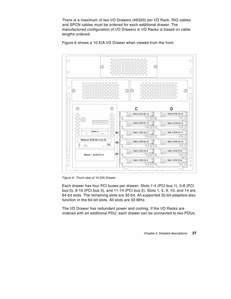
Figure 6 shows a 10 EIA I/O Drawer when viewed from the front.
Figure 6. Front view of 10 EIA Drawer
Each drawer has four PCI buses per drawer: Slots 1-4 (PCI bus 1), 5-8 (PCIbus 0), 9-10 (PCI bus 3), and 11-14 (PCI bus 2). Slots 1, 5, 9, 10, and 14 are64-bit slots. The remaining slots are 32-bit. All supported 32-bit adapters alsofunction in the 64-bit slots. All slots are 33 MHz.
The I/O Drawer has redundant power and cooling. If the I/O Racks areordered with an additional PDU, each drawer can be connected to two PDUs,
Chapter 2. Detailed descriptions 37
thus, making the I/O system highly available from a power supply point ofview.
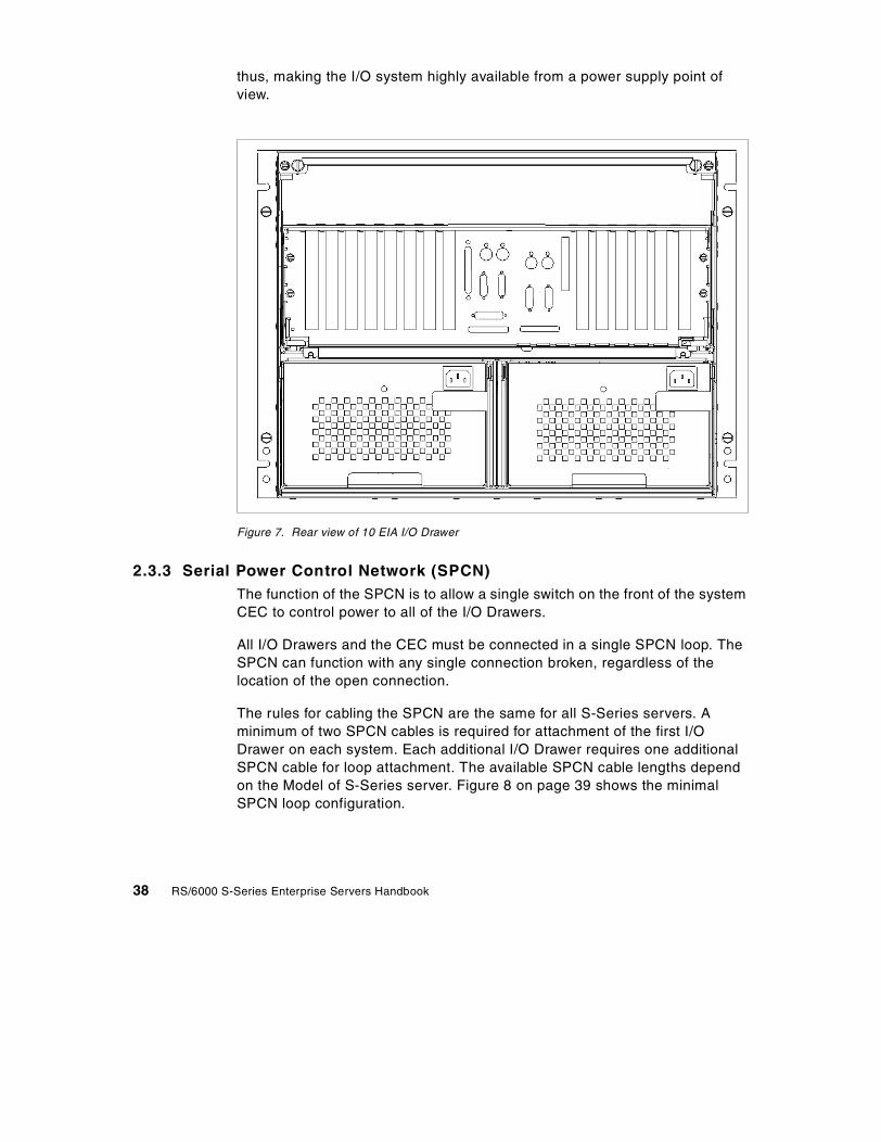
Figure 7. Rear view of 10 EIA I/O Drawer
2.3.3 Serial Power Control Network (SPCN)The function of the SPCN is to allow a single switch on the front of the systemCEC to control power to all of the I/O Drawers.
All I/O Drawers and the CEC must be connected in a single SPCN loop. TheSPCN can function with any single connection broken, regardless of thelocation of the open connection.
The rules for cabling the SPCN are the same for all S-Series servers. Aminimum of two SPCN cables is required for attachment of the first I/ODrawer on each system. Each additional I/O Drawer requires one additionalSPCN cable for loop attachment. The available SPCN cable lengths dependon the Model of S-Series server. Figure 8 on page 39 shows the minimalSPCN loop configuration.
38 RS/6000 S-Series Enterprise Servers Handbook
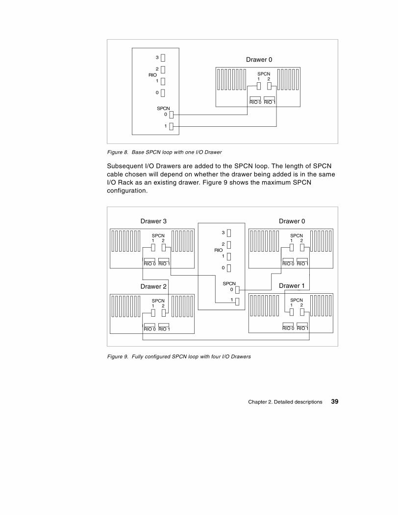
Figure 8. Base SPCN loop with one I/O Drawer
Subsequent I/O Drawers are added to the SPCN loop. The length of SPCNcable chosen will depend on whether the drawer being added is in the sameI/O Rack as an existing drawer. Figure 9 shows the maximum SPCNconfiguration.
Figure 9. Fully configured SPCN loop with four I/O Drawers
Drawer 0
0
1
2
3
RIO
1
0SPCN
RIO 0 RIO 1
SPCN1 2
Drawer 2
RIO 0 RIO 1
SPCN1 2
Drawer 3
RIO 0 RIO 1
SPCN1 2
Drawer 1
RIO 0 RIO 1
SPCN1 2
Drawer 0
RIO 0 RIO 1
SPCN1 2
0
1
2
3
RIO
1
0SPCN
Chapter 2. Detailed descriptions 39

2.3.4 Remote I/O cablingThe I/O Drawers are connected to the system CEC by a number of differentcables. The Remote I/O (RIO) cables provide the means by which data canbe transferred between the CPUs and memory in the CEC and the storageand network devices connected via PCI adapters in the I/O Drawers.
RIO connections operate at 250 MB/s in each direction, 500 MB/s duplex.The loop connection provides redundant paths; so, if a failure occurs in partof a cable, a warning message will be displayed, but the system will continueto operate.
The lengths of available RIO loop cable depend on the system beingconfigured. The RIO cables used for Model S80 systems have different partnumbers and feature codes than those used on Model S70 Advancedsystems. RIO cables from Model S70 Advanced systems must not be used onModel S80 systems.
The primary I/O Drawer must be installed and connected to RIO port 0 of theCEC. The connection must be made from RI0 port 0 of the CEC to RIO port 0of the primary I/O Drawer. This connection is required to make the primarydrawer the first drawer in the loop that allows the firmware to initialize thesystem. It also allows the system to find the boot device.
An RIO loop supports up to two drawers. Each S-Series server supports up totwo RIO loops. The configuration for a single I/O Drawer is very simple. Therecan only be one RIO loop since there is only one I/O Drawer. An example ofthis is shown in Figure 10 on page 41.
40 RS/6000 S-Series Enterprise Servers Handbook

Figure 10. RIO loop with one I/O Drawer
When adding a second drawer, you can cable the additional drawer into theexisting RIO loop. This requires one additional RIO cable. An example of thisis shown in Figure 11.
Figure 11. One RIO loop attached to two I/O Drawers
Drawer 0
RIO 0 RIO 1
SPCN1 2
0
1
2
3
RIO
1
0SPCN
Drawer 1
RIO 0 RIO 1
SPCN1 2
Drawer 0
0
1
2
3
RIO
1
0SPCN
RIO 0 RIO 1
SPCN1 2
Chapter 2. Detailed descriptions 41
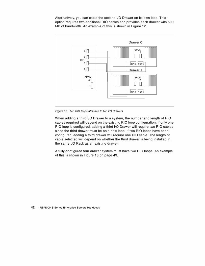
Alternatively, you can cable the second I/O Drawer on its own loop. Thisoption requires two additional RIO cables and provides each drawer with 500MB of bandwidth. An example of this is shown in Figure 12.
Figure 12. Two RIO loops attached to two I/O Drawers
When adding a third I/O Drawer to a system, the number and length of RIOcables required will depend on the existing RIO loop configuration. If only oneRIO loop is configured, adding a third I/O Drawer will require two RIO cablessince the third drawer must be on a new loop. If two RIO loops have beenconfigured, adding a third drawer will require one RIO cable. The length ofcable selected will depend on whether the third drawer is being installed inthe same I/O Rack as an existing drawer.
A fully-configured four drawer system must have two RIO loops. An exampleof this is shown in Figure 13 on page 43.
Drawer 1
RIO 0 RIO 1
SPCN1 2
Drawer 0
RIO 0 RIO 1
SPCN1 2
0
1
2
3
RIO
1
0SPCN
42 RS/6000 S-Series Enterprise Servers Handbook

Figure 13. Two RIO loops attached to four I/O Drawers
2.4 Upgrade paths to Model S80
Installed Model S70 Advanced systems can be converted to Model S80systems. This conversion requires replacement of the entire CentralElectronic Complex (CEC) including processors and system memory. Thesupport processor group, which includes the service processor card, mustalso be exchanged to provide the proper firmware for interfacing to the ModelS80 CEC. The Model S70 Advanced I/O Rack and drawers, PCI adaptercards, hard disks, and media devices carry forward to the upgraded ModelS80 system. This conversion preserves the existing system serial number.
Drawer 3
RIO 0 RIO 1
SPCN1 2
Drawer 2
RIO 0 RIO 1
SPCN1 2
Drawer 1
RIO 0 RIO 1
SPCN1 2
Drawer 0
RIO 0 RIO 1
SPCN1 2
0
1
2
3
RIO
1
0SPCN
Chapter 2. Detailed descriptions 43

The model upgrade consists of the following items:
• Central Electronics Complex (CEC) - The Model S70 Advanced CECbeing replaced is returned to IBM.
• Model S80 labels - Preserving the customers serial number.
• Model S80 publications.
Processor cards and I/O Drawer attachment hardware must be orderedseparately. The following items are required and must be ordered separately:
• One - First RS64 III Processor, 6-Way SMP 450 MHz, 8 MB L2 Cache(#5318)
• 2 GB Minimum System Memory (See Section 2.4.2, “S70 Advanced toS80 memory conversion” on page 45)
• Cabling for connection to the primary I/O Drawer includes:
• One - System Control And Initialization Cable - Upgrade Indicator(#8006)
• Two - Power Control Cable - Upgrade Indicator (#8008)
• Two - Remote I/O Cables (#3143 or #3144)
• One - Remote I/O Hub - Dual Loop - (#6503)
• One - Support Processor Group - Model Upgrade Only (#8326)
The following items must be carried forward from the system being upgraded:
• I/O Drawer attachment cables (#8006 and #8008 above)
• I/O Rack
• Primary and secondary I/O Drawers (including backplanes, SCSIadapters, and cables)
• PCI adapters
• Hard disk drives
• Media devices
2.4.1 S70 Advanced to S80 processor conversionModel S70 Advanced systems that are converted to Model S80 systems willrequire replacement of all system processors. The first Model S70 Advanced
The S70 Advanced Support Processor being replaced is returned to IBM.
Note
44 RS/6000 S-Series Enterprise Servers Handbook

4-way processor card can be replaced with the first Model S80 6-wayprocessor card via feature conversion. This processor conversion is onlyavailable at the time of initial model upgrade. A maximum of one S70Advanced 4-way processor card may be converted to one S80 6-wayprocessor card for each system being converted. The existing Model S70Advanced 4-way processor card being replaced is returned to IBM.
Table 9 shows the processor feature conversions that are available to ModelS70 Advanced customers who convert their systems to Model S80 systems:
Table 9. S70 Advanced to S80 processor conversion
2.4.2 S70 Advanced to S80 memory conversionModel S70 Advanced systems that are converted to Model S80 systems willrequire replacement of all system memory. This memory replacement will beimplemented by converting existing Model S70 Advanced memory features toModel S80 memory features. The memory conversions are only available atthe time of initial model upgrade and are allowed on a one-for-one featureconversion basis. A maximum of four Model S70 Advanced memory featuresmay be converted to Model S80 memory features for each system beingconverted from S70 Advanced to S80. The existing Model S70 Advancedmemory being replaced is returned to IBM.
The following memory feature conversions are available to Model S70Advanced customers who convert their systems to Model S80 systems:
Table 10. S70 Advanced to S80 memory conversion
From To
(#0504) RS64 II, 4-way SMP, 262 MHz (#5318) RS64 III, 6-way, SMP, 450 MHz
(#5312) RS64 II, 4-way SMP, 262 MHz (#5318) RS64 III, 6-way, SMP, 450 MHz
(#5314) RS64 II, 4-way SMP, 262 MHz (#5318) RS64 III, 6-way, SMP, 450 MHz
(#5316) RS64 II, 4-way SMP, 262 MHz (#5318) RS64 III, 6-way, SMP, 450 MHz
(#9404) RS64, 4-way SMP, 125 MHz (#5318) RS64 III, 6-way, SMP, 450 MHz
From To
1024 GB
(#4173) 1024 MB R1 Memory (#4190) 1024 MB Memory
(#4174) 1024 MB R1 Memory Select (#4190) 1024 MB Memory
2048 MB
Chapter 2. Detailed descriptions 45

(#4171) 512 MB R1 Memory (#4191) 2048 MB Memory
(#9168) Base 512 MB Memory (#4191) 2048 MB Memory
(#4173) 1024 MB R1 Memory (#4191) 2048 MB Memory
(#4174) 1024 MB R1 Memory Select (#4191) 2048 MB Memory
(#4175) 2048 MB R1 Memory (#4191) 2048 MB Memory
(#4176) 2048 MB R1 Memory Select (#4191) 2048 MB Memory
4096 MB
(#4171) 512 MB R1 Memory (#4192) 4096 MB Memory
(#9168) Base 512 MB Memory (#4192) 4096 MB Memory
(#4173) 1024 MB R1 Memory (#4192) 4096 MB Memory
(#4174) 1024 MB R1 Memory Select (#4192) 4096 MB Memory
(#4175) 2048 MB R1 Memory (#4192) 4096 MB Memory
(#4176) 2048 MB R1 Memory Select (#4192) 4096 MB Memory
(#4177) 4096 MB R1 Memory (#4192) 4096 MB Memory
(#4178) 4096 MB R1 Memory Select (#4192) 4096 MB Memory
8192 MB
(#4171) 512 MB R1 Memory (#4193) 8192 MB Memory
(#9168) Base 512 MB Memory (#4193) 8192 MB Memory
(#4173) 1024 MB R1 Memory (#4193) 8192 MB Memory
(#4174) 1024 MB R1 Memory Select (#4193) 8192 MB Memory
(#4175) 2048 MB R1 Memory (#4193) 8192 MB Memory
(#4176) 2048 MB R1 Memory Select (#4193) 8192 MB Memory
(#4177) 4096 MB R1 Memory (#4193) 8192 MB Memory
(#4178) 4096 MB R1 Memory Select (#4193) 8192 MB Memory
(#4179) 8192 MB R1 Memory (#4193) 8192 MB Memory
(#4180) 8192 MB R1 Memory Select (#4193) 8192 MB Memory
16384 MB
From To
46 RS/6000 S-Series Enterprise Servers Handbook
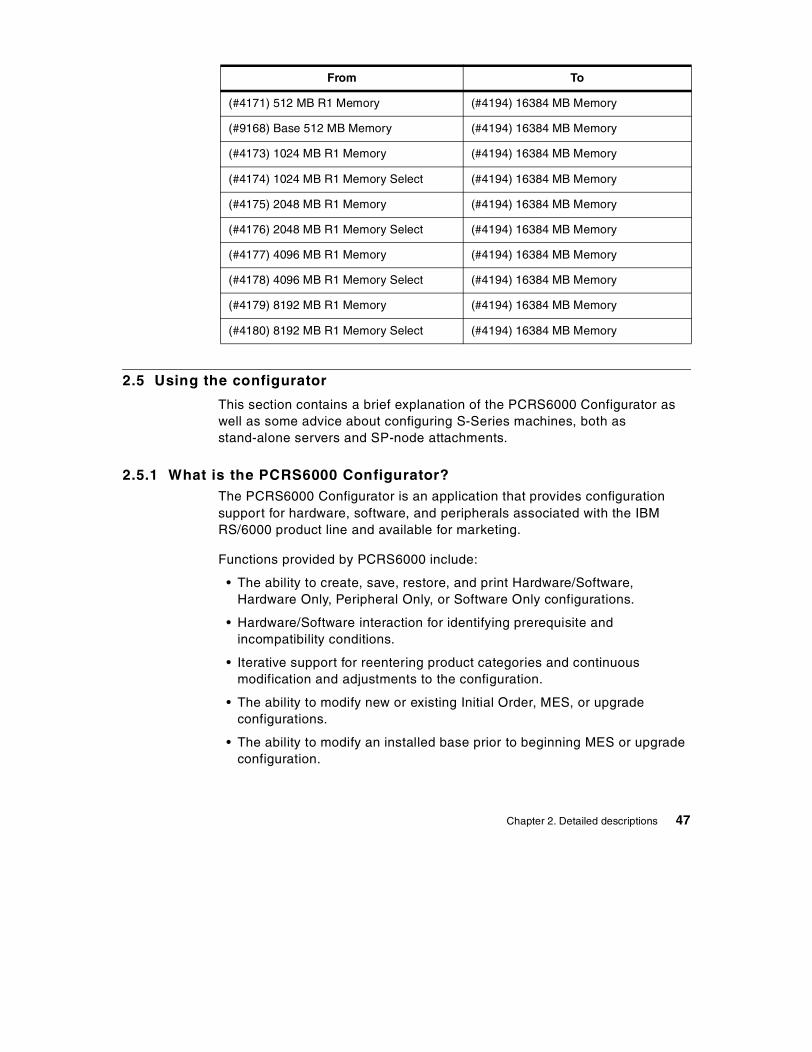
2.5 Using the configurator
This section contains a brief explanation of the PCRS6000 Configurator aswell as some advice about configuring S-Series machines, both asstand-alone servers and SP-node attachments.
2.5.1 What is the PCRS6000 Configurator?The PCRS6000 Configurator is an application that provides configurationsupport for hardware, software, and peripherals associated with the IBMRS/6000 product line and available for marketing.
Functions provided by PCRS6000 include:
• The ability to create, save, restore, and print Hardware/Software,Hardware Only, Peripheral Only, or Software Only configurations.
• Hardware/Software interaction for identifying prerequisite andincompatibility conditions.
• Iterative support for reentering product categories and continuousmodification and adjustments to the configuration.
• The ability to modify new or existing Initial Order, MES, or upgradeconfigurations.
• The ability to modify an installed base prior to beginning MES or upgradeconfiguration.
(#4171) 512 MB R1 Memory (#4194) 16384 MB Memory
(#9168) Base 512 MB Memory (#4194) 16384 MB Memory
(#4173) 1024 MB R1 Memory (#4194) 16384 MB Memory
(#4174) 1024 MB R1 Memory Select (#4194) 16384 MB Memory
(#4175) 2048 MB R1 Memory (#4194) 16384 MB Memory
(#4176) 2048 MB R1 Memory Select (#4194) 16384 MB Memory
(#4177) 4096 MB R1 Memory (#4194) 16384 MB Memory
(#4178) 4096 MB R1 Memory Select (#4194) 16384 MB Memory
(#4179) 8192 MB R1 Memory (#4194) 16384 MB Memory
(#4180) 8192 MB R1 Memory Select (#4194) 16384 MB Memory
From To
Chapter 2. Detailed descriptions 47
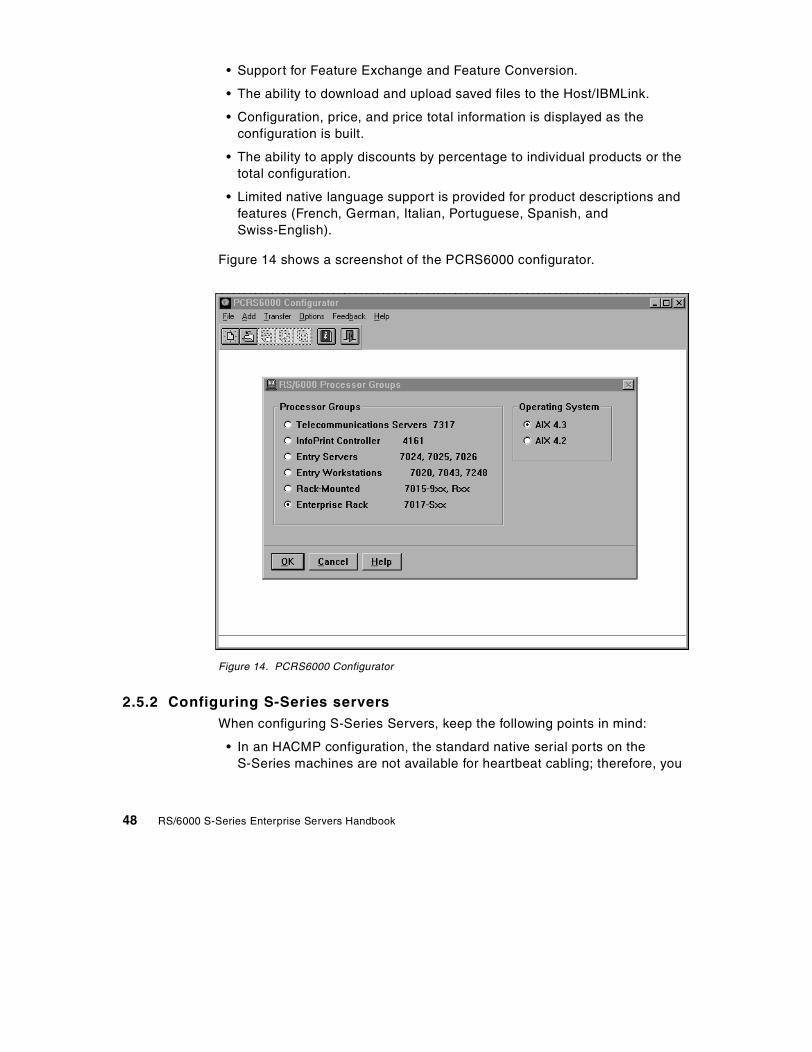
• Support for Feature Exchange and Feature Conversion.
• The ability to download and upload saved files to the Host/IBMLink.
• Configuration, price, and price total information is displayed as theconfiguration is built.
• The ability to apply discounts by percentage to individual products or thetotal configuration.
• Limited native language support is provided for product descriptions andfeatures (French, German, Italian, Portuguese, Spanish, andSwiss-English).
Figure 14 shows a screenshot of the PCRS6000 configurator.
Figure 14. PCRS6000 Configurator
2.5.2 Configuring S-Series serversWhen configuring S-Series Servers, keep the following points in mind:
• In an HACMP configuration, the standard native serial ports on theS-Series machines are not available for heartbeat cabling; therefore, you
48 RS/6000 S-Series Enterprise Servers Handbook

must install either the 8-port asynchronous adapter (#2943) withserial-to-serial cable (#3125) or the 128-port Asynchronous controller(#2944) with 128-port Asynchronous cable (#8136), rack-mountableRemote Asynchronous Node (#8136), RJ-45 to DB-25 converter cable(#8133), and serial-to-serial cable (#3125).
• Either an IBM-supported ASCII terminal with an attachment cable or anIBM-supported graphics display with an attachment cable and graphicsaccelerator is required for initial setup and must be available locally forservice. OEM asynchronous terminals are not recommended since theymay not transmit the same character sequence and, thus, will not berecognized by the Service Processor.
• SP Node Attachment configurations are described in Section 2.5.3,“Special considerations for SP external node attach” on page 51.
• Gigabit Fiber Channel Adapter (#6227) is available on an MES/Upgradebasis only.
2.5.2.1 Two S-Series Servers sharing an I/O RackIn special circumstances, the S-Series Servers can be ordered without an I/ORack. This configuration can be a good way of having multiple S-SeriesServers without requiring an I/O Rack for every system. This option savesmachine room floor space by reducing the footprint of the systems. It alsoreduces the overall cost of the system.
This configuration is not difficult to achieve, although some specialconsiderations must be taken when ordering.
When placing an order for multiple systems, the first system should beconfigured as normal. 10 EIA units of space in the I/O Rack should bereserved for the I/O Drawer of the second system. This is achieved byselecting feature code #0177 as a rack contents specify feature.
When configuring the second system, there will be a feature change thatindicates a rackless system order. The feature is selected in the rack optionsconfiguration screen, as shown in Figure 15.
Chapter 2. Detailed descriptions 49

Figure 15. Rack options dialog box
There are two ways of configuring a rackless system:
• (#7007) Rackless System Order - Plant Install - This feature allows asystem containing a single (primary) I/O Drawer to be ordered without anI/O Rack. The system primary I/O Drawer will be factory installed in the I/ORack of a companion system that specifies feature code #0177 to providethe required 10 EIA units rack space and two power outlets. Both systemsmust be ordered on the same customer order with the same scheduledfactory delivery date.
• (#7009) Rackless System Order - Field Install - This feature allows asystem containing a single (primary) I/O Drawer to be ordered without anI/O Rack. The system primary I/O Drawer will be field installed in the I/ORack of another system that provides the 10 EIA units rack space and twopower outlets required for the I/O Drawer.
7017-S80 I/O Drawers are only supported in 7017-S80 or 7017-S7A I/ORacks. Orders containing feature #7007 are subject to cancellation if acompanion system is not ordered with the same factory delivery scheduleand feature #0177 specified.
Note
50 RS/6000 S-Series Enterprise Servers Handbook

2.5.3 Special considerations for SP external node attachModel S80 and S70 Advanced servers can function as an attached SMPserver within the IBM RS/6000 SP environment operating under the control ofthe IBM Parallel Systems Support Programs for AIX. Up to 16 such systemsmay be attached in a single configuration. This interconnection can beaccomplished utilizing an ethernet connection and, optionally, using the IBMRS/6000 SP System Attachment Adapter (#8396).
Some I/O adapters available for the S70 Advanced and S80 systems are notsupported in the SP environment and must be removed. Refer to RS/6000 SPPlanning Volume 1, Hardware and Physical Environment, GA22-7280, for alist of currently-supported adapters.
IBM Parallel System Support Programs for AIX Version 3.1 (5765-D51), orlater, is required for an S-Series server system to function as an attachedSMP server within the IBM RS/6000 SP environment.
Each S-Series server system that is to function as an attached SMP serverwithin the IBM RS/6000 SP environment must have a minimum of oneethernet adapter. This adapter must be recognized by the system as en0 andmust reside in slot #5 of the primary I/O Drawer.
The RS/6000 SP-attached server must have the latest system and serviceprocessor firmware (microcode) installed.
The Control Workstation (CWS) must have sufficient serial port connectionsand CPU power to support the RS/6000 SP-attachment. The requirement istwo RS-232 attachments for each RS/6000 S-Series server that is to beattached. If the CWS does not have sufficient available RS-232 ports, youmay have to add one or more 8-port (#2943) or 128-port (#2944)Asynchronous adapters, assuming there are enough free adapter slots. If not,a larger capacity CWS will be required.
The SP-attached server requires attachment to an RS/6000 SP system withat least one frame containing at least one node and (if switch attached) theSPS (16-port) switch. The 49 inch short LowBoy frames with any switch andthe 79 inch tall frame with the HPS switch are not supported forSP-attachment. Note, the High Performance Switch hardware is not allowedin any configuration and the tall frame with the 8 port RS/6000 SP systemswitch is not allowed in any circumstance. A 10 meter switch cable is providedwith the SP-attach order through the RS/6000 SP system configurator.
If this is to be a switchless attachment to the RS/6000 S80 and RS/6000 S70Advanced servers, then the RS/6000 SP system must also be switchless.
Chapter 2. Detailed descriptions 51

There must be available (unused) switch node numbers in your SP SystemData Repository even though the switch is not being used. That means anRS/6000 S80 or RS/6000 S70 Advanced server cannot be attached to asingle frame system where all 16 nodes are occupied.
Only one RS/6000 SP System Attachment Adapter is permitted in eachSP-attached server. This is consistent with the rules for RS/6000 SP systemnodes.
A separately chargeable PSSP 3.1 license must be ordered against eachSP-attached server serial number.
If you are configuring a system order for an S-Series machine that is to beSP-attached to an existing SP system, you must also perform an MES orderagainst the SP system to configure the S-Series machine as an externalnode.
The RS/6000 SP system configurator session for all variations of SP-attachwill include the following when adding a SP node attachment:
• (#9122) NODE ATTACHMENT FEATURE - An order for this feature willgenerate an order for the two 15 Meter RS-232 cables for hardware controland S1TERM connectivity between the CWS and the SP-attached server.It also will generate an order for a 10 meter ground cable. It also trapssome data so that the RS/6000 SP system configurator session can keeptrack of how many nodes (real and logical) are in the system.
• (#9310) SWITCH CONNECTION CABLE - This feature is required only ifthe SP-attached server is switch attached. It results in the ordering of one10 meter switch connection cable. The 10 meter cable is the onlysupported length at this time.
• (#9123) FRAME ATTACHMENT FEATURE - This feature keeps track ofhow many frames are currently in your RS/6000 SP system. Since theS-Series SP-attached server is both a logical node and a logical frame inthe PSSP code logic, it is important to track this information to avoidexceeding allowable RS/6000 SP system limits for the number of frames.
• (#9222) NODE ATTACHMENT ETHERNET BNC BOOT FEATURE - Thisfeature will get a BNC cable to allow RS/6000 SP system Ethernetcommunications and booting with your SP-attached server, whetherswitch-attached or not.
• (#9223) NODE ATTACHMENT ETHERNET TWISTED PAIR BOOTFEATURE - This feature tracks the choice to incorporate the SP-attachedservers as part of an RS/6000 SP system Ethernet Twisted Pair network,
52 RS/6000 S-Series Enterprise Servers Handbook

but it provides no twisted pair cable. As in the past, the customer isresponsible for providing their own twisted pair Ethernet cables.
• (#5765-D51) PSSP 3.1 Software - feature for each SP-attached serverlicense, the features are as follows:
• (#5800) 4mm tape
• (#5801) 8mm tape
• (#5803) CD ROM
The charge features are different - as follows:
• (#4001) PSSP software on an RS/6000 SP system
• (#4002) PSSP software on an Externally Attached Server
For full details on configuring an S-Series server as a node in an SP system,refer to RS/6000 SP Planning Volume 1, Hardware and PhysicalEnvironment, GA22-7280.
2.6 Adapter restrictions
The S-Series PCI slot population rules are very complex and cannot easily beexplained in this book. Refer to the PCI Adapter Placement Reference,SA38-0538, for advice and guidance on the supported configurations ofadapters in RS/6000 systems. The placement reference contains informationon both maximum configurations and optimal configurations for bestperformance.
Extensive configuration rules and checking procedures have beenincorporated into the PCRS6000 configurator to ensure valid systemconfigurations. Configurations generated without utilizing the PCRS6000configurator may create orders that cannot be manufactured, resulting inpossible order rejection and/or delayed delivery.
There are 14 PCI slots split across 4 PCI buses in each I/O Drawer. Slotsassigned to each bus are: 1-4, 5-8, 9-10, and 11-14. Slots 1, 5, 9, 10, and 14
The RS/6000 SP System Attachment Adapter (#8396) must always belocated in slot #10 of the primary I/O Drawer. No adapters may be installedin slots #9 or #11 of the primary drawer when the SP attachment adapter isinstalled.
Note
Chapter 2. Detailed descriptions 53

are 64-bit slots. The remaining slots are 32-bit. 32-bit adapters can be used in64-bit slots.
System maximum limits for adapters and devices may not provide optimalsystem performance. These limits are given for connectivity and functionalityassurance.
Configuration limitations have been established to help ensure appropriatePCI bus loading, adapter addressing, and system and adapter functionalcharacteristics when ordering primary and secondary I/O Drawers. These I/ODrawer limitations are in addition to the individual adapter limitations shown inthe feature descriptions section.
The service processor must always be located in slot 8 of the primary I/ODrawer. To ensure proper functionality of the service processor, certain otheradapters, such as SSA adapters, cannot share a PCI bus with the serviceprocessor.
The service processor provides two serial ports for direct console attachmentand support processor use only. These ports are not to be utilized for otherfunctions, such as HACMP heartbeat cables or UPS interface.
Only two SSA adapters are allowed per PCI bus, with a maximum of 26 persystem. A maximum of five SSA adapters are allowed in the primary I/ODrawer while up to seven are allowed in each secondary I/O Drawer.
The S/390 ESCON Channel Adapter (#2751) is limited to four per system andtwo per I/O Drawer. These adapters must be located in drawers attached viathe primary I/O loop for addressing considerations.
The RS/6000 SP System Attachment Adapter (#8396) must always belocated in slot 10 of the primary I/O Drawer. No adapters may be installed inslot 9 or 11 of the primary drawer when the SP attachment adapter isinstalled.
The following adapters are limited to one per system:
• (#2708) Eicon ISDN DIVA PRO 2.0 PCI S/T Adapter
• (#2830) POWER GXT130P Graphics Adapter
• (#2838) POWER GXT120P Graphics Adapter
• (#6322) Service Processor (Model S70 Advanced)
• (#6326) Service Processor (Model S80)
• (#8396) RS/6000 SP System Attachment Adapter
54 RS/6000 S-Series Enterprise Servers Handbook

Chapter 3. Hardware architecture
Models in the S-Series have two or more physical enclosures connected by apower controller and I/O cables. The first enclosure is the CEC, whichcontains processor cards, memory, a memory controller, and a Remote I/O(RIO) controller, along with power supplies and cooling fans. The componentsin the CEC are packaged between metal sheets to form what are calledbooks. Book packaging provides greater protection for the cards, ensures thatthey are seated properly, and helps achieve optimum air flow within the CEC.
The second enclosure is a standard 19-inch black rack with a door added foraesthetics. The rack contains the primary SCSI I/O Drawer. Up to fourdrawers are supported per system. The second I/O Drawer can be housed inthe same rack as the first or in an additional rack. No more than two SCSI I/ODrawers are supported in a single rack.
3.1 RS64 III processor and card
The Model S80 uses the 450 MHz RS64 III processor, which is based on the262 MHz RS64 II used in the Model S70 Advanced. Both are 64-bit,PowerPC-compatible, four-way superscalar implementations. They areoptimized for commercial workloads. The Model S80’s processors inparticular are designed to perform well running applications that place heavydemands on system memory. The RS64 III architecture addresses both theneed for very large working sets and low latency. Latency is measured by thenumber of CPU cycles that elapse before requested data or instructions canbe utilized by the processor.
The new processors combine IBM advanced copper chip technology with aredesign of critical timing paths on the chip to achieve greater throughput.The L1 instruction and data caches have been doubled to 128 KB each. Newcircuit design techniques were used to maintain the one cycle load-to-uselatency for the L1 data cache.
L2 cache performance on the RS64 III processor has been significantlyimproved. Each processor has an on-chip L2 cache controller and an on-chipdirectory of L2 cache contents. The cache is four-way set associative. Thismeans that directory information for all four sets is accessed in parallel.Greater associativity results in more cache hits and lower latency, whichimproves commercial performance.
Using a technique called Double Data Rate (DDR), the new 8 MB StaticRandom Access Memory (SRAM) used for L2 is capable of transferring data
© Copyright IBM Corp. 1999 55

twice during each clock cycle. The L2 interface is 32 bytes wide and runs at225 MHz (half processor speed), but, because of the use of DDR, it provides14.4 GBps of throughput.
Figure 16 contains a diagram of the processor card layout used on the ModelS80. There are six RS64 III processors per CPU card sharing two systembuses that connect to the memory controller complex.
Figure 16. RS64 III processor card
The RS64 III processor has five pipeline execution units: Branch, load/store,fixed point, complex fixed point, and floating point. The complex fixed pointunit provides support for multiplication and division math. There is a dispatchbuffer that can hold up to 16 current instructions, a technique that helpsreduce latency. It also has an eight-deep branch buffer. The processor cansustain a decode and execution rate of up to four instructions per cycle.
CPU
L2
CPU
L2
CPU
L2
CPU
L2
CPU
L2
Address
Data
RS64 III
L2 CacheController
L2 CacheDirectory
128 KB 128 KBL1 Data L1 Instr
CPU450 MHz
CPU
8 MB L2 Cache
L2
32 byte DDR 14.2 GB/s
Two system bus connections per CPU card16 bytes @ 150 MHz = 2.4 GB/s per busTotal bandwidth 4.8 GB/s per CPU card
56 RS/6000 S-Series Enterprise Servers Handbook
All processor arrays use fault detection and correction techniques, such asredundancy, error checking and correction (ECC), parity, and retry. Together,these tools promote high reliability, availability, and data integrity. Thisenables full fault detection and correction coverage within the CEC.
In summary, the RS64 III features include:
• 128 KB on-chip L1 instruction cache
• 128 KB on-chip L1 data cache with one cycle load-to-use latency
• On-chip L2 cache directory that supports up to 8 MB of off-chip L2 SRAMmemory
• 14.4 GBps L2 cache bandwidth
• 32 byte on-chip data buses
• 450 MHz operating frequency
• 4-way superscalar design
• Five stage deep pipeline
3.2 Model S80 memory controller complex
Ten system data buses link the Model S80 processor cards to the memorycontroller complex and the RIO hub. Each processor card has two buses thatconnect to two interconnected data flow switches. Each switch connectsdirectly to two quads of Synchronous Dynamic Random Access Memory(SDRAM). Each switch also connects to its own dedicated port on the RIOhub.
Each switch consists of four data flow switch chips and a separate data flowcontrol chip. The data flow switch chips are at the core of the memorycontroller. An SMP bus arbiter chip in the controller complex prevents switchcontention.
Figure 17 on page 58 contains a diagram of the memory controller complexlayout. The eight system buses connecting the processor cards and the twosystem buses connecting the RIO ports are 128 bits wide and run at 150 MHzto provide a total bandwidth of 24 GBps. Memory ports are 512 bits wide andoperate at 75 MHz. The four memory ports have an aggregate bandwidth of19.2 GBps. The total memory controller complex switch bandwidth is animpressive 43.2 GBps. Transfer buffers are used in the switch to queue trafficif the needed connections are not immediately available.
Chapter 3. Hardware architecture 57

Figure 17. Model S80 system switch complex
In addition to the data flow switches, the design incorporates high-functionaddress and data buffers to minimize latency. Addressing is done via a
6-wayCPUCard
6-wayCPUCard
6-wayCPUCard
6-wayCPUCard
Switch Complex Switch ComplexI/O Hub
I/ODrawer
I/ODrawer
I/ODrawer
I/ODrawer
MemoryQuad
MemoryQuad
MemoryQuad
MemoryQuad
Each memory bus: 64 Bytes @ 75 MHz = 4.8 GB/sTotal memory bandwidth: 4.8 GB/s x 4 = 19.2 GB/s
Each system bus: 16 Bytes @ 150 MHz = 2.4 GB/s
Each RIO Bus = 8 bits @ 250 MHz= 250 MB/s in each direction = 500 MB/s Duplex
Total system bus bandwidth: 2.4 GB/s x 10 = 24 GB/s
Total switch bandwidth = 19.2 GB/s memory bandwidth + 24 GB/s Processor and I/O = 43.2 GB/s
58 RS/6000 S-Series Enterprise Servers Handbook

separate 64 bit path. Cross-port traffic between processor cards is queued atthe switch as needed.
The high function address and data buffer chips break logical buses intosmaller physical units. This allows the clocking frequency and, thus, thetransfer speed, to be increased. The buffers allow each of the system busesto support up to 2.4 GB/s of throughput.
The memory controller complex is mounted on a two-sided active backplane.The processors and memory are inserted as books. The I/O subsystem isconnected to the complex via a pair of new RIO hub chips. These chips areon a replaceable I/O interface card that will make upgrades easier in thefuture.
One of the features of this memory complex design is its ability to handle thenext generation of processors. The system is designed to accommodateupgrades without losing its overall excellent balanced performance.
3.3 RS64 II processor and card
The Model S70 Advanced uses the 262 MHz RS64 II processor, which isbased on the 125 MHz RS64 processor used in the RS/6000 Model S70Enterprise Server. Both are 64-bit, PowerPC-compatible, four-waysuperscalar implementations. They are optimized for commercial workloads.
The RS64 II processor has five pipeline execution units: Branch, load/store,fixed point, complex fixed point, and floating point. The complex fixed pointunit provides support for multiplication and division math. There is a dispatchbuffer that can hold up to 16 current instructions, a technique that helpsreduce latency. It also has an eight-deep branch buffer. The processor cansustain a decode and execution rate of up to four instructions per cycle.
All processor arrays use fault detection and correction techniques, such asredundancy, error checking and correction (ECC), parity, and retry. Together,these tools promote high reliability, availability, and data integrity. Thisenables full fault detection and correction coverage within the CEC.
The RS64 II features include:
• 64 KB on-chip L1 instruction cache
• 64 KB on-chip L1 data cache with one-cycle load-to-use latency
• 8.4 GBps L2 cache bandwidth
• 32 byte on-chip data buses
Chapter 3. Hardware architecture 59
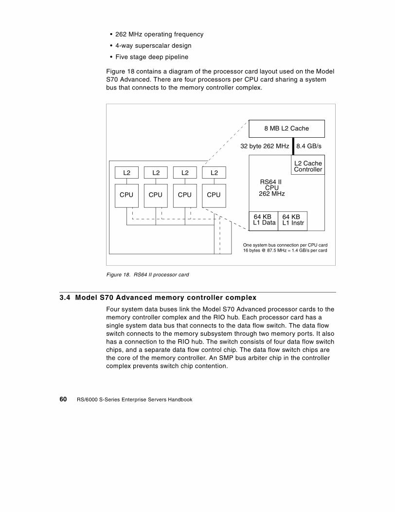
• 262 MHz operating frequency
• 4-way superscalar design
• Five stage deep pipeline
Figure 18 contains a diagram of the processor card layout used on the ModelS70 Advanced. There are four processors per CPU card sharing a systembus that connects to the memory controller complex.
Figure 18. RS64 II processor card
3.4 Model S70 Advanced memory controller complex
Four system data buses link the Model S70 Advanced processor cards to thememory controller complex and the RIO hub. Each processor card has asingle system data bus that connects to the data flow switch. The data flowswitch connects to the memory subsystem through two memory ports. It alsohas a connection to the RIO hub. The switch consists of four data flow switchchips, and a separate data flow control chip. The data flow switch chips arethe core of the memory controller. An SMP bus arbiter chip in the controllercomplex prevents switch chip contention.
CPU
L2RS64 II
L2 CacheController
64 KB 64 KBL1 Data L1 Instr
CPU262 MHz
8 MB L2 Cache
One system bus connection per CPU card16 bytes @ 87.5 MHz = 1.4 GB/s per card
32 byte 262 MHz 8.4 GB/s
CPU
L2
CPU
L2
CPU
L2
60 RS/6000 S-Series Enterprise Servers Handbook

Figure 19 contains a diagram of the layout of the memory controller complex.
Figure 19. Model S70 Advanced system switch complex
The three system buses connecting the processor cards and the system busconnecting the RIO ports are 128 bits wide and run at 87.5 MHz to provide atotal bandwidth of 5.6 GBps. Memory ports are 512 bits wide and operate at
4-wayCPUCard
4-wayCPUCard
4-wayCPUCard
Switch ComplexI/O Hub
I/ODrawer
I/ODrawer
I/ODrawer
I/ODrawer
MemoryQuad
64 Byte memory port
Total memory bandwidth:
Each system bus: 16 Bytes @ 87.5 MHz = 1.4 GB/s
Each RIO Bus = 8 bits @ 250 MHz= 250 MB/s in each direction = 500 MB/s Duplex
Total system bus bandwidth: 1.4 GB/s x 4 = 5.6 GB/s
MemoryQuad
MemoryQuad
MemoryQuad
MemoryQuad
@ 43.75 MHz = 2.8 GB/s
2.8 GB/s x 2 = 5.6 GB/s
Total switch bandwidth = 5.6 GB/s memory bandwidth + 5.6 GB/s Processor and I/O = 11.2 GB/s
Chapter 3. Hardware architecture 61

43.5 MHz. The two memory ports have an aggregate bandwidth of 5.6 GBps.The total memory controller complex switch bandwidth is 11.2 GBps.
The memory controller complex is mounted on a two-sided active backplane.The processors and memory are inserted as books. The I/O subsystem isconnected to the complex via a set of RIO hub chips.
3.5 Memory
System memory for the S-Series comes in books that are plugged intoreserved slots in the CEC. Some slots are accessible from the front of theCEC and some from the rear. See Section 2.1.4, “Memory” on page 14, fordetails of the memory quad layout of the Model S80. See Section 2.2.3,“Memory” on page 24, for details of the memory quad layout of the Model S70Advanced.
The base Model S80 comes with 2 GB of SDRAM. The base for the ModelS70 Advanced is 1 GB. The maximum memory on a Model S80 is 64 GB; ona Model S70 Advanced, it is 32 GB.
The S-Series models use a form of memory designated R1. Memory comesin quads that must be installed in specific locations within the CEC. Memorymodules are soldered inside their protective books, which minimizes failuresand faults caused by connectors or sockets. Memory from a Model S70Advanced must be replaced when upgrading to a Model S80 because thelatter runs at a faster speed.
The slot layout differs somewhat between the Model S80 and Model S70Advanced. There are four quads on a Model S80: A, B, C, and D. The ModelS70 Advanced has those quads and one more, quad E. The E quad canoptionally accommodate much slower DIMM-based memory from oldersystems being upgraded to a Model S70 Advanced. If DIMM memory is used,quads B, C, and D must be empty, and R1 memory must be installed in quadA. Although this option allows the use of memory from the system beingupgraded, it restricts the maximum capacity and performance of the memorysubsystem.
On the Model S70 Advanced, the memory system is accessed through twoseparate ports. Optimization is achieved by equalizing (as much as possible)the amount of memory on each of the ports. Quads A and D are on one port,and quads B, C, and E are on the other. To ensure that both memory ports areused by the system to maximize memory bandwidth, it is important that ModelS70 Advanced systems be configured with a minimum of two memory quads.
62 RS/6000 S-Series Enterprise Servers Handbook

On the Model S80, memory is accessed through four separate ports. Eachhalf of the system switch complex is connected to two quads. Refer to Figure17 on page 58 for a graphical representation. Memory quads A and D are onone half of the switch, and quads B and C are on the other half. To ensure thatboth halves of the memory controller complex are used by the system to utilizethe available switch and system bus bandwidth, it is important that Model S80systems be configured with a minimum of two memory quads.
To get best the performance from either S-Series server, sort all memoryfeatures by quad size from largest to smallest. Install the largest memory featurein quad A, insert the next largest memory feature in quad B, and so on. Continueinserting memory quads in the available slots alphabetically, with the smallerfeatures following the larger.
On the Model S80, memory cards M01 through M03 and M08 through M10are accessible from the front of the system, and M11 through M15 and M20through M24 are accessible from the rear. Refer to Figure 2 on page 15 andFigure 3 on page 16 for details of the physical layout. Memory for the ModelS80 comes in increments of 1 GB (4 x 256 MB), 2 GB (4 x 512 MB), 4 GB (4 x1024 MB), 8 GB (2048 MB), and 16 GB (4 x 4096 MB). All cards in a quadmust be the same size.
On the Model S70 Advanced, memory cards M01 through M06 and M10 throughM15 are in the front of the CEC, and M16 through M19 and M21 through M24 arein the rear. Refer to Figure 4 on page 26 and Figure 5 on page 27 for details ofthe physical layout. R1 memory for the Model S70 Advanced comes inincrements of 512 MB (4 x 128 MB), 1 GB (4 x 256 MB), 2 GB (4 x 512 MB), 4GB (4 x 1024 MB), and 8 GB (4 x 2048 MB).
The memory subsystem has single-bit error correction and double-bit errordetection (ECC). The Model S80 memory cards feature redundant modulesthat will support up to one in 14 memory modules not working. The memory isscrubbed by the controller when it is idle, a feature that is designed to detectsoft errors and reduce hard failures.
3.6 Remote I/O connections
On the Model S80, the Remote I/O (RIO) subsystem connects to the CEC viathe I/O hub chips on a new replaceable I/O interface card. On the Model S70Advanced, the chips are mounted directly on the backplane. In either case,four RIO connections are supported allowing a maximum of two RIO loops.The RIO connections are scalable, high-speed, point-to-point interfacesdesigned for low-latency high-bandwidth connections between two boards or
Chapter 3. Hardware architecture 63

boxes. Each RIO bus supports up to 500 MB/s total or 250 MB/s in eachdirection concurrently. RIO cables connect the CEC to the I/O devices locatedin the I/O Drawers. The RIO connections are set up as loops. The I/O hubchips direct the traffic around the loop in an optimal way for performance, andthey redirect traffic if there are link errors.
The new RIO hub interface chip on the Model S80 offers improved bufferingto enhance the effectiveness of the I/O interface.
These RIO connections are the key to allowing an expandable number of I/ODrawers that are physically separated from the CEC. In turn, this feature alsoenables the high number of PCI buses and slots.
3.7 I/O Drawer
The S-Series servers use an enhanced I/O Drawer. The drawers have fullyredundant power supplies and fans that can be serviced without shuttingdown the system. The drawers improve overall cooling by using morepowerful, variable-speed fans that increase air flow when one fails. An LEDpanel on each drawer displays status information.
The primary I/O Drawer for Model S80 and Model S70 Advanced systemscontains:
• The I/O planar
• The service processor
• The native I/O card
• Two independent hot-pluggable disk bays (six-packs)
• One available media bay
• One floppy disk drive
• One CD-ROM
• 14 PCI slots (11 available)
• One keyboard port
• One mouse port
• Two serial ports and one parallel port
In the primary I/O Drawer, one PCI slot will be used for the service processor,and two will be used by the controllers for the media bay and first disksix-pack. If the second six-pack is used, a third controller is required.However, one PCI Dual Channel Ultra2 SCSI adapter (#6205) can be used to
64 RS/6000 S-Series Enterprise Servers Handbook

replace two PCI Single-Ended Ultra SCSI adapters (#6206), thus, freeing oneadapter slot. The dual channel controllers will run at Ultra speed. The 14 PCII/O slots consist of five 64-bit and nine 32-bit PCI slots. The 64-bit PCI slotsare 1, 5, 9, 10, and 14.
The original seven EIA S70 I/O Drawers are not supported on the Model S80.
On the S-Series I/O Drawers, the majority of the function is implemented onthe I/O planar. In each drawer, a single RIO-to-I/O bridge bus chip convertsthe RIO bus to the local mezzanine bus. The mezzanine bus is also called theI/O bridge bus. The I/O bridge bus drives four PCI bridge chips, each with itsown local PCI bus containing two or four slots each. Each bus worksindependently. The RIO-to-I/O bridge chips have “IN” and “OUT” RIO ports toenable redundant and chainable loop connection of RIO devices. The I/Obridge bus runs at 66 MHz and has a 528 MB/s bandwidth.
3.8 I/O bridge bus
The local I/O bridge bus is a reduced signal version of the system bus thathas been optimized for I/O. The I/O bridge bus uses a multiplexed 64-bitaddress and data path. The I/O bridge bus is parity checked for address,data, and control errors. Each bus request is range checked and positivelyacknowledged for improved error detection. The I/O bridge bus operates inpipeline mode. New requests can be issued before previous requests arecompleted. The bridges and other chips in the I/O path provide significantqueuing.
3.9 PCI buses
The PCI bridge chips on both systems convert the I/O bridge bus to PCI.There are 14 PCI-compliant slots running at 33 MHz per I/O Drawer. PCI 2.1cards are supported. Four PCI bridges are used per I/O planar. One of thePCI bridge chips drives two 64-bit PCI slots. The other three PCI bridgeseach drive one 64-bit PCI slot and three 32-bit PCI slots. This configurationperformance balances the load. Five volts and 3.3 volts are available at theslots. Five volt PCI signaling conventions are used.
The 64-bit PCI slots have a maximum throughput of 266 MB/s. The 32-bit PCIslots have a maximum throughput of 133 MB/s. It is important to note that noPCI-to-PCI bridges are used in this performance-optimized design.PCI-to-PCI Bridges significantly limit the useful bandwidth of the related PCIslots.
Chapter 3. Hardware architecture 65
3.10 S80 firsts
The Model S80 represents significant new packaging, new components, andnew levels of function for the RS/6000 family. It is the first RS/6000 to use thesignificantly-improved copper technology RS64 III processor and its matchedmemory controller complex. The Model S80 is the first RS/6000 to support24-way SMP computing. It is also the first to support 64 GB of memory. TheS-Series models are the first RS/6000s to support an expandable I/Osubsystem that is packaged separately from the rest of the system.
The S-Series is the first RS/6000 with hardware-based memory scrubbing,which reduces soft error exposures to very low levels. The S-Series is alsothe first in the RS/6000 family to offer mainframe-class burnt-in components,which significantly improve reliability over typical industry devices. TheS-Series also features new levels of error recovery, detection, and reporting.
The S-Series is the first RS/6000 to use Predictive Failure Analysis to monitorthe error rates on DASD, memory, processors, L1 and L2 caches, and remoteI/O. The Model S80 is the first RS/6000 system to allocate one out of every 14main memory chips for use as a replacement in the event of single-bit errors.Redundancy is also provided for data traffic between the CEC and the I/ODrawer via a looped cable. If the cabling to the I/O Drawer is experiencingerrors, the hardware will redirect the I/O traffic through an alternate path onthe loop.
66 RS/6000 S-Series Enterprise Servers Handbook
Chapter 4. Operating an S-Series server
This chapter describes some of the new features of AIX 4.3.3, which areparticularly useful in large commercial environments.
Although many of these features can be used on any RS/6000 server, theyare designed to be of most benefit on large SMP systems, such as theS-Series machines.
4.1 AIX 4.3.3
AIX is an integrated UNIX 98 Branded operating environment for POWER-and PowerPC-based workstations, symmetric multiprocessor, and scalableparallel computing systems. This environment enables both the developmentand execution of computing applications across the RS/6000 product line.
AIX Version 4.3.3 is a third modification release building on theindustry-leading strength and stability of AIX 4.3. It is also the first release ofAIX to be influenced by Project Monterey. Project Monterey is an initiative ledby IBM with SCO, Sequent, and Intel to deliver a single UNIX product line thatspans RS/6000 systems, IA-32-, and upcoming IA-64-based systems.
AIX Version 4.3.3 with enhanced 64-bit scalability and functionality provides:
• Significant AIX software scalability enhancements for 24-way SMPsystems (RS/6000 S80 Server support).
• AIX Workload Management system with a policy-based method formanaging system workload and system resources. See Section 4.2,“Workload management” on page 68.
• AIX exploitation of SecureWay Directory for AIX users and groups.
• Increased scalability, performance, capacity, and capability of e-businesswith Web serving acceleration, Cisco EtherChannel, and Quality ofService (QoS) administration and support
• TCP/IP enhancements, such as SOCKS V5, gratuitous ARP, andSendmail, upgrade to Version 8.9.3 with anti-spamming features.
• Improved system availability with support for online Journal File System(JFS) backup and concurrent mirroring and striping. See Section 4.3.1,“Online JFS backup” on page 74 and Section 4.3.2, “Concurrent stripingand mirroring” on page 76.
• Enhanced RAS and improved serviceability features for problemdetermination.
© Copyright IBM Corp. 1999 67

• A port of the Sun Solaris 2.5 NIS+ network information managementsystem in addition to the current NIS support.
• IBM AIX Developer Kit, Java Technology Edition Version 1.1.8.
• Enhanced Ease-of-Use capabilities including additional Web-basedSystem Manager Task Guides and SMIT support.
• X11R6.3, the Broadway release, OpenGL enhancements, and graPHIGSenhancements
For full details on the enhancements included in AIX Version 4.3.3, refer tothe AIX Version 4.3 Differences Guide, SG24-2014.
4.2 Workload management
This section describes the AIX Workload Management (WLM) system, whichprovides a policy-based method of managing system workload andresources.
4.2.1 OverviewWorkload management is designed to give the system administrator morecontrol over how the scheduler and virtual memory manager (VMM) allocateresources to processes. This can be used to prevent different classes of jobsfrom interfering with each other and to allocate resources based on therequirements of different groups of users.
The major use of workload management is expected to be for large systemswith many CPUs and large amounts of memory, such as Model S70Advanced and Model S80 systems. These large systems are often used forserver consolidation, where workloads from many different server systems,such as print, database, general user, and transaction processing systems,are combined into a single large system to reduce the cost of systemmaintenance and administration. These workloads often interfere with eachother and have different goals and service agreements. Workloadmanagement is designed to address these problems. The same issues canoccur in a single environment where the user base has very different systemusage characteristics or the system managers have different priority usercommunities.
Another use of workload management is to provide isolation between usercommunities with very different system behaviors. This can prevent effectivestarvation of workloads with certain behaviors, such as interactive or low CPU
68 RS/6000 S-Series Enterprise Servers Handbook

usage jobs, from workloads with other behaviors, such as batch or highmemory usage jobs.
These usages have two different issues that workload management mustaddress. First, targets for the amount of resources available to differentworkloads are required. These targets are not absolute; rather, they shouldbe achieved over the long term to provide a degree of fairness. The secondissue that workload management must address is boundaries on the amountof resources that a workload can receive. These boundaries can be in termsof maximum resources available and minimum resources that must be madeavailable. These boundaries are not intended to be the major means ofseparating workloads; rather, they are intended to address special situationswhere targets are not enough to provide sufficient isolation.
4.2.2 Managing resources with WLMWLM monitors and regulates the CPU utilization and physical memoryconsumption of the threads and processes that are active on the system.Using a set of class assignment rules provided by the system administrator,new processes are automatically assigned to a class by WLM uponexecution. Classes are grouped into tiers, which indicate the relativeimportance of each class. Each class has a set of minimum and maximumlimits for each resource managed by WLM. In addition, each class has atarget value for each resource. This target is representative of the amount ofthe resource that would be optimal for the jobs in the class.
4.2.2.1 ClassesA class defines common resource requirements for a group of processes. It ispossible to create up to 29 classes with up to 16 characters for the classname.
The system administrator defines a set of rules that allow the system todetermine which class a process belongs to. Class assignment rules arebased on the user ID, group ID, and executable name of the process.
When WLM is enabled, the assignment of jobs to classes according to theclass rules is automatic. WLM was designed as a Set & ForgetAdministration.
There are two default classes that WLM creates at initial environment setup:
System Class This class defines the resources for the operating system. Itincludes all kernel processes and all privileged processesthat are not automatically assigned to another class.
Chapter 4. Operating an S-Series server 69
Default Class This default class is used as a catch-all at the end of theclass rules file. All processes that are not assigned to anyother class will be assigned to the default class.
4.2.2.2 TiersTiers are the values that indicate the relative importance of classes to WLM.Each class belongs to a tier, with the importance defined by the tier value,which ranges from 0 to 9 (0 being the most important tier and 9 being theleast important).
Tier numbers allow the grouping of classes by equivalent importance.Classes in less important tiers get resources that classes in more importanttiers do not require.
4.2.2.3 SharesThe target for usage of different types of resources is specified with shares.The shares are specified as relative amounts of usage between the differentclasses.
If a class does not have any processes in it, the available resource is dividedamong the remaining classes according to their share values.
Possible share values range from 1 to 65,000. The default target share, ifunspecified, is 1.
Figure 20 shows what happens when a class with 5 shares has no activejobs. The resources that would have been used by the class are madeavailable to other classes.
Figure 20. Example share distribution
0 10 20 30 40 50 60 70 80 90 100
12 shares 16 shares 3 shares
0 10 20 30 40 50 60 70 80 90 10012 shares 5 shares 16 shares 3 shares
Entitled:
Actual:
70 RS/6000 S-Series Enterprise Servers Handbook

Each of the active classes still has the same share value, but the realpercentage of resource allocated is larger, since there is a smaller totalnumber of shares.
4.2.2.4 Minimum and maximum resource limitsThe different resources controlled by WLM can be limited by the followingvalues:
• The minimum percentage of the resource that must be made availablewhen requested. The possible values are integers from 0 to 100. Ifunspecified, the default value is 0.
• The maximum percentage of a resource that can be made available, evenif there is no contention for the resource. The possible values are integersfrom 1 to 100. If unspecified, the default value is 100.
Keep in mind that the minimum limit reserves resources and the maximumlimit restricts resources. The resource target for a class is determined by thenumber of shares for the class and the number of shares for other activeclasses. The resource target may also be increased or reduced becauselimits take precedence over shares.
Resource limit values are specified by resource type in the resource limit filewithin stanzas for each class. The limits are specified as a minimum tomaximum range separated by a hyphen (-) with whitespace ignored. Eachlimit value is followed by a percent sign (%).
WLM does not place hard constraints on the values of the resource limits.The following are the only constraints:
• The minimum range must be less than or equal to the maximum range.
• The sum of the minimum of all classes within a tier cannot exceed 100.
WLM enforces the maximum range to ensure that a class or process within aclass is not given more resource than the specified value. Note that, in thecase of a memory constraint, swapping performance can become very poorfor processes within the constrained class. Memory minimums for otherclasses should be used before imposing a memory maximum for any class.
A minimum value constraint on a class means that processes within the classare always allowed to get resources up to the minimum. WLM cannotguarantee that processes actually reach their minimum limit. This depends onhow the processes use their resources and on other limits that may be ineffect. For example, a class may not be able to reach its minimum CPUentitlement because it cannot get enough memory.
Chapter 4. Operating an S-Series server 71
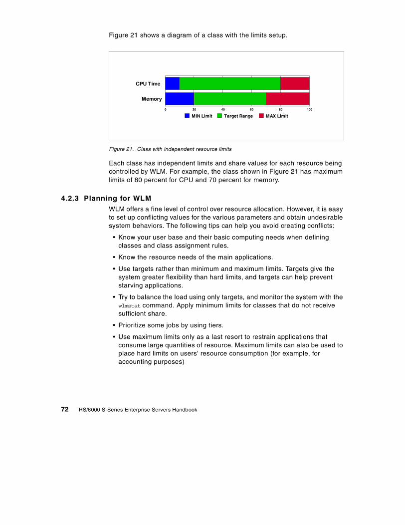
Figure 21 shows a diagram of a class with the limits setup.
Figure 21. Class with independent resource limits
Each class has independent limits and share values for each resource beingcontrolled by WLM. For example, the class shown in Figure 21 has maximumlimits of 80 percent for CPU and 70 percent for memory.
4.2.3 Planning for WLMWLM offers a fine level of control over resource allocation. However, it is easyto set up conflicting values for the various parameters and obtain undesirablesystem behaviors. The following tips can help you avoid creating conflicts:
• Know your user base and their basic computing needs when definingclasses and class assignment rules.
• Know the resource needs of the main applications.
• Use targets rather than minimum and maximum limits. Targets give thesystem greater flexibility than hard limits, and targets can help preventstarving applications.
• Try to balance the load using only targets, and monitor the system with thewlmstat command. Apply minimum limits for classes that do not receivesufficient share.
• Prioritize some jobs by using tiers.
• Use maximum limits only as a last resort to restrain applications thatconsume large quantities of resource. Maximum limits can also be used toplace hard limits on users' resource consumption (for example, foraccounting purposes)
CPU Time
Memory
0 20 40 60 80 100
MIN Limit Target Range MAX Limit
72 RS/6000 S-Series Enterprise Servers Handbook
4.2.4 Starting WLMWLM is an optional service of AIX and can be started manually orautomatically. The wlmcntrl command allows you to start and stop WLM.
All processes existing in the system before WLM is started remainunclassified and are not monitored by WLM. A future PTF to the WLM systemwill add the ability to reclassify processes already running when WLM isstarted.
In normal system mode, it is best to start WLM early in the systeminitialization process. For example, WLM could be started by an inittab entry,such as the following:
wlm:2:once:wlmcntrl -d /etc/wlm/standard > /dev/console 2>&1
4.2.5 WLM user interfacesThe administration of WLM can be performed using Web-based SystemManager (wsm), SMIT, the command line, or by modifying configuration filesdirectly.
This provides the administrator flexibility to include WLM commands in shellscripts or use a graphical interface to set up or modify the WLM configuration.
Figure 22 on page 74 shows the WLM control application using the wsm userinterface.
Chapter 4. Operating an S-Series server 73

Figure 22. WLM graphical interface
4.3 Additional AIX features
This section describes some of the new AIX features that will be of greatbenefit in the large commercial server environments commonly found onModel S70 Advanced and Model S80 machines.
4.3.1 Online JFS backupThe Journaled File System (JFS) has been enhanced to support file systemonline backup. This capability allows a mirrored copy of a file system to beused for backup purposes. A mirror copy of the file system is split off,mounted read-only, and available for backup. The primary copy of the filesystem is still mounted and in use. This enables the system administrator toback up a consistent copy of the file system data while another copy is stillmounted and in use by users and applications. After the backup is complete,the administrator can reintegrate the backup mirror copy and resynchronize itwith the other mirror copies.
74 RS/6000 S-Series Enterprise Servers Handbook

There are some conditions that have to be met in order to perform an onlinebackup.
• The JFS logical volume and JFS log logical volume must be mirrored.
• The number of mirrored copies of both the JFS logical volume and the JFSlog logical volume must be the same.
It is recommended to keep file system activity as minimal as possible duringJFS online JFS backup events.
After the backup activities are finished, it is possible to remove the read-onlyfile system in order to have maximum data availability.
The process of splitting off and mounting the backup file system isaccomplished by use of the chfs command. The correct set of options to thiscommand will split off the required copy of the mirrored logical volume andmount the copy in read only mode at a specified mount point. For example,assuming that /data is a file system on a triple mirrored logical volume, thefollowing command splits off the 3rd copy of the mirror and mounts it readonly as /backup:
# chfs -a splitcopy=/backup -a copy=3 /data
When the chfs command completes, the snapshot copy of the file system ismounted and ready for the backup procedure to commence.
Once the backup procedure has completed, the snapshot copy of the filesystem needs to be reintegrated with the live data. This is performed in twosteps. The first step is to unmount the snapshot copy of the file system. Thesecond step is to use the rmfs command to remove access to the snapshotcopy. At this point, the snapshot data is not actually deleted. The rmfs
command removes the temporary logical volume device, which was createdto access the snapshot copy. It then starts the syncvg process in thebackground to resynchronize the snapshot copy with the live data. Forexample:
# umount /backup# rmfs /backup
Splitting a mirrored copy of a file system means that one copy istemporarily dedicated to backup activities and is not available to providedata availability. It is recommended that you have a triple mirror of the filesystem so you can recover from any disk problem that happens before thebackup copy has been reintegrated with the file system.
Note
Chapter 4. Operating an S-Series server 75

Only the data blocks that have changed since the snapshot was taken areactually synchronized. The duration of this operation depends on a number offactors including the size of the file system, the number of blocks that havechanged, and the speed of the disk subsystem on which the file systems arestored.
4.3.2 Concurrent striping and mirroringFor some time, the Logical Volume Manager (LVM) in AIX has provided theability to create striped or mirrored logical volumes, although a logical volumecould not be both striped and mirrored. In this AIX release, the LVM combinesRAID 1 (mirror) data availability with RAID 0 (striped) performance bysupporting (entirely in software) a striped logical volume with mirrors. Thisfeature further enhances data availability in high-performance striped logicalvolumes by tolerating disk failures. The remaining disks in the striped mirrorcopy continue to service striped units contained on these disks. Thereplacement of a disk where only the partitions on the new disk aresynchronized is provided through the migratepv and replacepv commands.
In addition, all logical volumes can now utilize a new partition allocation policycalled Super Strict. This Super Strict policy does not allow partitions from onemirror to share a disk with any partitions from a second or third mirror, thus,helping to further reduce the probability of data loss resulting from a diskfailure.
These new functionalities are not backward compatible; therefore, newvolume groups supporting these features cannot be imported and used withprevious versions of AIX.
4.3.2.1 RAID Levels 0 and 1RAID 0 is also known as data striping. Conventionally, a file is written outsequentially to a single disk. With striping, the information is split into chunksand the chunks written to (or read from) a series of disks in parallel. Thereare two main performance advantages to this:
• Data transfer rates are higher for sequential operations due to theoverlapping of multiple I/O streams.
• Random access throughput is higher because access pattern skew iseliminated due to the distribution of the data. This means that with datadistributed evenly across a number of disks, random accesses will mostlikely find the required information spread across multiple disks and, thus,benefit from the increased throughput of more than one drive.
76 RS/6000 S-Series Enterprise Servers Handbook

Although RAID configurations are normally associated with availability, keepin mind that RAID 0 is only designed to increase performance.
RAID 1 is also known as disk mirroring. In this implementation, duplicatecopies of each chunk of data are kept on separate disks. If any disk in thearray fails, the mirrored twin can take over. Read performance can beenhanced as the disk with its actuator closest to the required data is alwaysused, thereby, minimizing seek times.
The response time for writes can be somewhat slower than for a single diskdepending on the write policy; the writes can either be executed in parallel forspeed or serially for safety. Writing in parallel means that the write processwill complete in the time taken for the slowest drive to finish in the mirroredpair; this is quick, but it means that a failure in writing to one of the pair ofdisks is not immediately detectable. In contrast, writing sequentially meansthat the write to the mirrored copy is not initiated until the first write hassuccessfully completed. This is slower, but any errors are immediatelydetectable. Mirroring improves response time for read-mostly applicationsand improves availability at the expense of cost, since twice (or three times)as many disks are required as disk space.
RAID 1 is best-suited to applications that require high data availability andgood read response times and in settings where cost is secondary.
Table 11 compares the relative characteristics of different RAID levels.
Table 11. Characteristics of different RAID levels
It is important to keep in mind that each different level of RAID configurationhas advantages and disadvantages. A combination of striping and mirroringprovides high performance and high availability, but there is a high cost.
RAIDLevel
Availabilitymechanism
Capacity Performance Cost
0 none 100% high medium
1 mirroring 50% medium high
0+1 mirroring 50% high high
5 parity 80% medium medium
Chapter 4. Operating an S-Series server 77

4.3.3 Fast device configurationThe AIX configuration manager now allows multiple device configurationmethods to run in parallel during system boot. This will produce a fasterreboot when multiple devices of the same type, such as multiple SCSI disks,TTYs, and multiport asynchronous adapters, are connected to an AIX system.A serialization mechanism is used when the configuration managerrecognizes that new devices have been added to the system. This causes thenew devices to be sequentially configured.
Systems with a large number of asynchronous I/O adapters benefit from areduction in both machine boot time and duration of the cfgmgr command.Generally, each asynchronous I/O adapter can take up to five minutes to beconfigured. With this new feature, up to 16 device configuration methods canrun in parallel.
4.4 General AIX improvements for large systems
Some AIX improvements will be particularly beneficial for large SMP systems.This section gives a brief description of some of these changes.
4.4.1 Increased threads and process limitsIn previous AIX versions, the number of system threads and processes wereeach limited to 131072. In some large SMP systems, the number of threadsand processes could reach the limit. In AIX 4.3.3, these numbers have beenextended to 524288 for threads and 174080 for process limits.
4.4.2 Multiple run queues with load balancingOn SMP systems, AIX 4.3.3 implements multiple run queues. Each processornow has a local run queue in addition to the original system-wide global runqueue.
When new threads are created, they are added to the system-wide global runqueue. When a processor is looking for a thread to dispatch, it will examinethe global run queue in addition to its local run queue and choose the highestpriority thread. Once a thread is on a processors local run queue, it will tend
RAID 0 mainly improves sequential workloads. For heavy randomworkloads and high availability needs, you should consider using RAID 1only.
Note
78 RS/6000 S-Series Enterprise Servers Handbook

to stay on that run queue and, thus, always be run on the same processor.This increases the probability that the data and instructions required to runthe thread will still be in the cache of the processor, thus, reducing the needto fetch instructions and data from main memory.
Periodic load balancing takes place automatically to ensure that allprocessors have similar numbers of threads in their local run queues and toprevent threads from bottle necking on a single processor.
The multiple run queues improve system performance by dramaticallyreducing lock contention for the global run queue and increasing processoraffinity for individual threads. In turn, this reduces the overhead on the cacheand memory subsystem, thus, allowing greater system throughput.
4.4.3 SMP scalability improvementsIn addition to the changes to the run queue system, many other changeshave been made to the process management system. Most of the changesare aimed at minimizing lock contention in the kernel, which is of much moreimportance now that 24-way SMP systems are supported. Some of thechanges include analyzing and improving the code being run while particularkernel locks are held. Other situations called for implementing new moregranular locks to reduce contention. One area to benefit from this is theprocess table lock.
4.5 PCI Dual Channel Ultra2 SCSI Adapter (#6205)
The PCI Dual Channel Ultra2 SCSI Adapter is a 64-bit adapter and is anexcellent solution for high-performance SCSI applications. The PCI DualChannel Ultra2 SCSI Adapter provides two SCSI channels (buses). EachSCSI bus can either be internal or external and supports a data rate of up to80 MBps, up to twice the maximum data transfer rate of previous Ultra SCSIadapters, which was 40 MBps.
In order to achieve an Ultra2 SCSI bus data rate of up to 80 MBps and alsomaintain a reasonable drive distance, the adapter utilizes Low VoltageDifferential (LVD) drivers and receivers. In order to utilize this Ultra2 80 MBpsperformance, all attaching devices or subsystems must also be Ultra2 LVDdevices. If any device is not Ultra2 LVD, the adapter will switch its SCSI bus tosingle-ended (SE) performance and interface at the lower SE SCSI bus datarate of the device.
Two industry-standard VHDCI 68 pin connectors are mounted on theadapter's end bracket allowing attachment of various LVD and SE external
Chapter 4. Operating an S-Series server 79
subsystems. The 0.3 meter, VHDCI to P, Mini-68 pin to 68 pin (#2118)converter cable can be used with older external SE subsystems to allowconnection to the VHDCI connector on the PCI Dual Channel Ultra2 SCSIAdapter.
Any supported RS/6000 system can be set up to boot from the PCI DualChannel Ultra2 SCSI Adapter (#6205). If you are running with AIX 4.3.3 orlater software, this adapter has native boot support as part of that level of AIXsoftware. If you are running with 4.2.1 software, the following procedureapplies in order to boot using the PCI Dual Channel Ultra2 SCSI Adapter:
• The designated boot SCSI disk can be located under the covers of aprocessor unit or in an external SCSI storage unit.
• AIX version 4.2.1 must be loaded to the designated SCSI boot disk usingthe AIX Network Install Manager (NIM) before booting from the SCSI bootdisk.
• The system with a designated SCSI boot disk must have a networkconnection with another RS/6000 system performing the NIM Masterfunction to perform the install. On RS/6000 SP systems, a similar networkinstall is performed from a control workstation.
• Once AIX 4.2.1 with updates is installed on the designated SCSI boot diskand the system is configured for booting, booting takes place from theboot disk drive without any support from the control processor or NIMMaster, and the system does not have to be connected to the network atboot time.
80 RS/6000 S-Series Enterprise Servers Handbook

Chapter 5. Reliability, availability, and serviceability
Reliability, availability, and serviceability (described as a collective term,RAS) describe how well a system can perform its intended function ondemand and how quickly problems and errors can be repaired. Commercialservers running mission-critical applications need strong RAS capabilities.RAS encompasses techniques for reducing faults and minimizing theirimpacts, shortening repair time, and enabling faster problem resolution.
In the S-Series, RAS begins with the development of architectures that givehigh priority to these characteristics. The emphasis on RAS begins in productdevelopment, where designs are tested, evaluated, and optimized. Concernfor reliability continues through the manufacturing and distribution processes,where quality is continually evaluated and carefully measured againstdocumented standards. Finally, the focus on RAS extends to service andsupport, where real-world experience is measured against design criteria.Hardware warranty and maintenance support receive undivided attentionwithin IBM, and significant customer problems are addressed by teams ofexperts.
The processes IBM follows in designing, testing, manufacturing, andservicing a product are periodically audited and certified for compliance withInternational Standards Organization (ISO) 9000 guidelines.
5.1 Designed for higher RAS
During the development of the S-Series, a major effort has been made toanalyze single points of failure within the central electronic complex. Theprocessors, L1 and L2 cache, system memory, memory controller complex,and the remote I/O subsystem have been designed to provide mainframe-likelevels of reliability. They undergo additional stress testing and screening bysuppliers above and beyond what is required of industry-standardcomponents used in many UNIX systems today.
The S-Series design aids in the recognition of intermittent errors that areeither corrected dynamically or reported for further isolation and repair. Paritychecking on the system bus, cyclic redundancy checking (CRC) on theremote I/O bus, and the use of error correcting code on memory andprocessors contribute to outstanding RAS characteristics. Redundant arrayswith cyclic redundancy checking are implemented in the power controller cardand the operator panel. The service processor arrays are redundant and useCRC checking.
© Copyright IBM Corp. 1999 81

The Model S80 does memory scrubbing, which is the process of reading thecontents of memory during idle time and checking and correcting anysingle-bit errors that may have accumulated. The Model S80 also does bitsteering (replacing failing storage with spares). In the new system, there is a14:1 ratio between live and spare memory bits.
During the boot sequence, built-in self test (BIST) and power-on self test(POST) routines check the processors, cache, and associated hardwarerequired for a successful system start. These tests run every time the systemis powered on.
Additional testing can be selected at boot time to fully verify the systemmemory and check the chip interconnect wiring. When a system reboots aftera hard failure, it performs extended mode tests to verify that everything isworking properly and that nothing was compromised by the failure. Thisbehavior can be overridden by the systems administrator.
The S-Series RAS design enhancements include:
• Automatic error capture and problem isolation
• Dynamic error recovery
• Single-bit error correction, double-bit error detection on internal processorarrays, and L1 and L2 cache and system memory
• Bit steering and scrubbing on memory
• Redundant power supplies and cooling fans providing fault tolerance andconcurrent maintenance for those subsystems
• Predictive failure analysis on processors, memory, RIO, and disk
• Processor boot-time deallocation of resources based on run-time errors
• Highly-reliable, stress-tested components
• Concurrent diagnostics
5.2 Service processor
The service processor and IBM Service Director for RS/6000 workindependently and together to achieve high levels of reliability, availability,and serviceability on the S-Series servers.
An independent microprocessor, the service processor occupies a 32-bit PCIslot in the primary I/O Drawer in the Model S80 and Model S70 Advanced. Itcomes installed in slot 8. The service processor runs its own firmware andhas access to non-volatile memory and hardware components within the
82 RS/6000 S-Series Enterprise Servers Handbook

central electronic complex. It can control system behavior underpredetermined conditions. The firmware has an asynchronous menu-driveninterface that can be accessed either locally or via modem from a remotesupport site. If desired, the local systems administrator can mirror the remoteterminal and keyboard maintaining oversight and eliminating the need toshare passwords with service personnel. This is called console mirroring.
During initialization, the service processor monitors diagnostic routines thateventually culminate in control of the system being turned over to theoperating system. Even then, the service processor continues to monitorhardware, environmental conditions, and, if so configured, the operatingsystem. If a fatal hardware or software problem brings the system down, theservice processor can automatically call support, the customer’s own helpdesk, or a pager number.
During its run-time monitoring of the hardware, if the service processordetects a non-fatal error that could develop into one that would bring thesystem down, it logs the problem in NVRAM and notifies AIX that it has errorinformation for the error log. On the AIX side, the NVRAM will be accessed bythe errdemon, and the problem will be entered in the AIX error log. An errorlogged in this manner will trigger an error log analysis, and, if Service Directorhas been configured, a service call will be placed to IBM, and the customer’shelp desk will be notified of the situation.
If a fatal error occurs during run-time, the system will halt. Depending onwhether a reboot policy has been set, the system will attempt to restart itself.The service processor can be configured to call home and report the problembefore attempting the restart. Typically, such calls would go to IBM, thecustomer’s help desk, a pager carried by an on-call technician, or somecombination of contacts. If the system is restarted, firmware will cause theservice processor to deallocate the failing module.
Other capabilities of the service processor include the ability to remotelypower-off/power-on the system, read its own and system POST error logs,and read vital product data (VPD). The service processor can change thebootlist, thus, enabling an alternate boot source. It can also view the bootsequence history, which lists the progress indicators that appeared in theoperator panel LCD window during the last boot. The service processor alsoenables the systems administrator to establish password protection of thefirmware menus, view the boot sequence history, and change operatingsystem surveillance and reboot policies.
Chapter 5. Reliability, availability, and serviceability 83

Updates to service processor and system firmware should be performed bytrained personnel. The updates are available from the following RS/6000support page on the Internet:
http://www.rs6000.ibm.com/support/micro
Code can be downloaded directly to a server and then installed, or it may bedownloaded as a file on a separate workstation. The file is then copied to theModel S80 or Model S70 Advanced and installed. The firmware can beupdated remotely using diagnostic Service Aids or AIX command line options.
By default, a backup copy of the prior version of firmware is maintained on thesystem so that it can be booted with the older version if necessary. At thesystem administrator’s discretion, the new firmware can be copied to thealternate storage location so that the two copies are identical, providingredundant firmware capability in case of corruption.
5.3 Service Director for RS/6000
Service Director ships automatically on all RS/6000s including the S-Seriesmodels. There is no charge for its use as long as the system is covered bywarranty or an IBM maintenance agreement. Groups of machines can runService Director with one machine serving as a single point of control and thelink to IBM service.
The mission of Service Director is to monitor hardware and analyzerecoverable faults and report them. Fatal errors that cause the system tocrash can be reported via the service processor. If desired, Service Directorcan be set up to automatically place a service call to IBM when it detects aproblem requiring an on-site visit. Alternatively, it can pass an alert to a helpdesk so that the customer can decide whether to place a service call, or itcould do both. Service Director can send alerts as electronic mail to a limitednumber of addresses specified by the systems administrator.
Service Director is menu-driven. The screens can be accessed through theSystems Management Interface Tool (SMIT). The program enables moreeffective management of hardware support, allowing administrators to quicklyand easily view the details of problems that have occurred, the status of opencalls, and the machine’s service history.
Service Director requires a modem. It may share a modem used by theservice processor.
84 RS/6000 S-Series Enterprise Servers Handbook

Service Director is designed to automatically report hardware problemsbased on default settings. However, the customer may modify the settings toprevent Service Director from placing a call, such as during hardwareupgrades and testing or if the failing component is not covered by an IBMservice agreement. The program will also automatically notify anadministrator by E-mail before expiration of a warranty or service agreement,giving the customer time to sign or renew a maintenance contract.
5.4 Additional system RAS features
Many server components, such as disk drives, power supplies, and coolingfans, are now hot-swappable; so, many common repairs can be made withoutstopping applications and taking the system offline. For example, with a RAIDcontroller and hot-pluggable disks, normal operation can continue, perhaps ina slightly degraded mode, while a failed drive is repaired.
The Model S80 brings new levels of availability and serviceability to theenterprise server. Within the CEC, the extra power supply providesredundancy in case of failures in either the bulk or regulated powersubsystems. Concurrent repair is supported on the bulk supplies while theregulators will require a controlled system shutdown before repairs can bemade. Optional uninterruptible power supply (UPS) systems are supportedand recommended for mission-critical servers.
The CEC cooling subsystem has what is called N+1 redundancy. That is,there is one blower more than the number required to keep the systemrunning. If one fails, repairs can be made without shutting down the system.The fans can also adjust their speed to partially compensate for a singlefailure.
Constant power monitoring hardware assists in the detection of early powerloss and notifies the operating system to attempt an orderly shutdown. Thissame power monitoring hardware detects the loss of redundant bulk powersupplies, regulators, fans, and blowers and reports them to the operatingsystem for logging in the system error log and for notification for deferredmaintenance.
With enhanced AIX diagnostics available with AIX 4.3.3, systemadministrators can keep track of diagnostic activity more effectively by usingthe new diagnostic event log. This log can be viewed by using the DisplayPrevious Diagnostic Results task under concurrent diagnostics. Tasks andservice aids within diagnostics have been ordered alphabetically for improvedease of use.
Chapter 5. Reliability, availability, and serviceability 85
A diagnostic exerciser has been added for processors to enhance problemdetermination. It provides a means of verifying both memory and processorrepairs previously detected by error log analysis.
Auto-restart options for the server, when enabled, are designed to reboot thesystem automatically following:
• Unrecoverable software error
• Software hang
• Fatal hardware error
• Environmentally-induced (AC power) failure
AIX 4.3.3 removes the prohibition against mirroring a dump device. AIX willnot complain about the mirrored devices, but it will only write to and read fromthe primary copy. Additionally, the Logical Volume Manager supports onlinebackup of journaled file systems.
The latest release of AIX also supports mirroring of striped file systems,enabling RAID 0 + 1 to improve performance and protect against disk failures.
The Kernel Debugger (kdb) is a tool being added to the AIX system to providea symbolic debugger for the AIX kernel, kernel extensions, and devicedrivers. There is also a kdb command, which is an alternative to the currentcrash command, to allow examination of system crash dumps.
These standard high-availability features, coupled with the optional HighAvailability Cluster Multi-Processing (HACMP) program, provide unmatchedavailability in the UNIX marketplace.
5.5 AIX RAS
As part of basic program design, operating systems developed by IBM havehistorically mandated recovery processing in both the mainline program andseparate recovery routines. However, a significant percentage of AIX codeoriginated outside of IBM. Consequently, recovery processing, such as thatemployed in IBM mainframe operating systems, is not the norm in AIX.
The classical approach to recovery is largely based on the premise ofkeeping the system or application alive at any cost. This approach grew out ofan environment in which each system was essentially stand-alone, supportedhundreds of users, and took a long time to restart. Today, even in largemultiuser environments, many customers require that recovery processing besubject to a time limit. They have concluded that rapid termination with quick
86 RS/6000 S-Series Enterprise Servers Handbook
restart or takeover by another application or system is preferable to a delayedrestart of the one that failed.
Serviceability is the ability to diagnose and correct or recover from an errorwhen it occurs. The serviceability capabilities and enablers in AIX arereferred to as the software service aids. The primary software service aidsare error logging, system dump formatting, and tracing.
The software service aids provide a common set of tools for performingproblem determination and problem source identification for AIX software.Problem determination is the name IBM gives to those activities performed indetermining whether a malfunction is caused by hardware or software. Thoseactivities that take place after problem determination to determine the specificmalfunctioning hardware or software component are referred to as problemsource identification.
With proper instrumentation in the software, the software service aids enablethe customer to determine whether a problem is caused by a defect inhardware or software. If a problem is due to malfunctioning hardware orsoftware, the service aids lead the customer to place a service call andenable him or her to report an accurate description of the problem. If aproblem is not due to malfunctioning hardware or software, the service aidsshould lead the customer to problem resolution without requiring anunnecessary service call.
Chapter 5. Reliability, availability, and serviceability 87

88 RS/6000 S-Series Enterprise Servers Handbook

Appendix A. Installation requirements
This appendix details the environmental, electrical, and installationrequirements of the S-Series systems including physical dimensions,clearances, and power requirements.
A fully-configured S-Series system consists of a CEC, at least one I/O Rack,and at least one I/O Drawer.
A.1 Central Electronic Complex
Table 12 details the specifications and requirements for the Model S80Central Electronic Complex (CEC). Table 13 on page 90 details thespecifications and requirements for the Model S70 Advanced CEC.
The CEC component of Model S80 and Model S70 Advanced systems is onlyavailable in 240 Volt single phase configurations. No three-phase options areavailable. Each CEC requires a single electrical connection.
Table 12. Model S80 Central Electronic Complex
Dimensions Metric Imperial
Height 1577 mm 62.0 in
Width 567 mm 22.3 in
Depth 1041 mm 40.9 in
Weight Metric Imperial
Minimum 400 kg 880 lbs
Electrical
Power source loading(Maximum in KVA)
2.129 KVA
Voltage range (V ac) 200 - 240
Frequency (Hertz) 50 - 60
Thermal output (Maximum) 6904 BTU/hr
Power requirements (Maximum) 2023 watts
Power factor 0.92 to 0.98
Inrush current1 43 amps
© Copyright IBM Corp. 1999 89

1Inrush currents occur only at initial application of power, no inrush occursduring normal power off-on cycle.
Table 13. Model S70 Advanced Central Electronic Complex
Maximum altitude 2135 m (7100 ft)
Operating Non-operating
Temperature Range10 to 37.8oC 1 to 60oC
50 to 100oF 34 to 140oF
Humidity (Noncondensing) 8 to 80% 8 to 80%
Wet Bulb Requirements 23oC (73oF) 23oC (73oF)
Noise Emissions Operating Idle
LWAd 7.0 bels 7.0 bels
LpAm N/A N/A
<LpA>m N/A N/A
Impulsive or prominent discretetones
No No
Dimensions Metric Imperial
Height 1577 mm 62.0 in
Width 567 mm 22.3 in
Depth 1041 mm 40.9 in
Weight Metric Imperial
Minimum 400 kg 880 lbs
Electrical
Power source loading(Maximum in KVA)
1.887 KVA
Voltage range (V ac) 200 - 240
Frequency (Hertz) 50 - 60
Thermal output (Maximum) 5796 BTU/hr
Power requirements (Maximum) 1698 watts
Power factor 0.9
90 RS/6000 S-Series Enterprise Servers Handbook

1Inrush currents occur only at the initial application of power; no inrushoccurs during the normal power off-on cycle.
A.2 I/O Rack
Depending on the configuration of the system, you will require at least oneS-Series I/O Rack. The specifications of the I/O Rack are the same for theModel S80 and Model S70 Advanced systems. Table 14 shows thespecifications for the S-Series I/O Rack.
Each I/O Rack requires an electrical connection for each Power DistributionUnit (PDU). If you configure an I/O Rack with two PDUs, it will require twoelectrical connections.
Table 14. S-Series I/O Rack
Inrush current1 102 amps
Maximum altitude 2135 m (7100 ft)
Operating Non-operating
Temperature Range10 to 37.8oC 1 to 60oC
50 to 100oF 34 to 140oF
Humidity (Noncondensing) 8 to 80% 8 to 80%
Wet Bulb Requirements 23oC (73oF) 23oC (73oF)
Noise Emissions Operating Idle
LWAd 7.0 bels 7.0 bels
LpAm N/A N/A
<LpA>m N/A N/A
Impulsive or prominent discretetones
No No
Dimensions Metric Imperial
Height 1577 mm 62.0 in
Width 650 mm 25.5 in
Depth 1019 mm 40.1 in
Weight Metric Imperial
Appendix A. Installation requirements 91

A.3 10 EIA I/O Drawer
Model S80 and Model S70 Advanced systems use an identical 10 EIA I/ODrawer. The I/O Drawer has dual redundant power supplies and requires twoconnections on the PDU of the I/O Rack in which it is installed. Table 15details the specifications and requirements of the I/O Drawer.
Table 15. S-Series 10 EIA SCSI I/O Drawer
Base rack 159 kg 349 lbs
Electrical
See specifications for drawers or enclosuresTemperature Range
Humidity Requirements
Noise Emissions
Dimensions Metric Imperial
Height 440 mm 17.3 in
Width 443.2 mm 17.5 in
Depth 843.2 mm 33.2 in
Weight Metric Imperial
Minimum configuration 89 kg 195 lbs
Maximum configuration 93 kg 206 lbs
Electrical
Typical power source loading(in KVA)
0.4 KVA
Maximum power source loading(in KVA)
1.0 KVA
Voltage range (V ac) 200 - 240 (autoranging)
Frequency (Hertz) 50 / 60
Thermal output (Typical) 1228 BTU/hr
Thermal output (Maximum) 3071 BTU/hr
Power requirements (Typical) 360 watts
Power requirements (Maximum) 900 watts
92 RS/6000 S-Series Enterprise Servers Handbook

A.4 Physical space requirements
Multiple I/O Racks can be placed adjacent to one another, with a 75 to 125mm (3 to 5 in.) gap. Only the racks at each end of the installation require thefull 915 mm (36 in.) clearance. Figure 23 on page 94 details the minimuminstallation and service clearances required for S-Series servers.
Power factor 0.9
Inrush current 170 amps
Maximum altitude 2135 m (7000 ft)
Operating Non-operating
Temperature Range10 to 40oC 10 to 52oC
50 to 104oF 50 to 125.6oF
Humidity (Noncondensing)without tape drive
8 to 80% 8 to 80%
Humidity (Noncondensing)with tape drive
20 to 80% 20 to 80%
Wet Bulb without tape drive 27oC (80oF) 27oC (80oF)
Wet Bulb with tape drive 23oC (73oF) 27oC (80oF)
Noise Emissions Operating Idle
LWAd 5.9 bels 5.3 bels
LpAm N/A N/A
<LpA>m N/A N/A
Impulsive or prominent discretetones
No No
Appendix A. Installation requirements 93
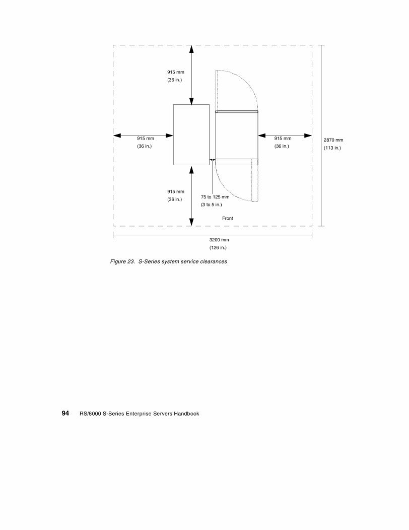
Figure 23. S-Series system service clearances
2870 mm
(113 in.)
3200 mm
(126 in.)
915 mm
(36 in.)
915 mm
(36 in.)
915 mm
(36 in.)
915 mm
(36 in.)
75 to 125 mm
(3 to 5 in.)
Front
94 RS/6000 S-Series Enterprise Servers Handbook
Appendix B. A practical guide to the service processor
Each S-Series server comes with a service processor to help maintain highavailability and reliability and serviceability (RAS). The service processor alsomakes it possible to perform many maintenance and support tasks from aremote location via modem.
Even when dial-in support is not contemplated, customers should be aware ofthe capabilities for calling out to report serious system errors. In addition,there are settings in the service processor menus that control the behavior ofthe system after a power outage and following a hardware or software error.Finally, customers should understand the purpose of system and serviceprocessor firmware, and they should know how to get updates.
B.1 How to access the service processor menus
To access the service processor menus, the systems administrator needs toaccess one of the native serial ports: S1 or S2. If remote dial-in support isenabled, one of the ports needs to have an asynchronous modem attachedand configured. The other port may have an ASCII terminal attached, or itmay have a leased-line or dial-up connection to a remote customer supportlocation. The service processor menus give an administrator a great deal offlexibility in deciding which ports to enable and whether to allow dial-out onlyor to support dial-in as well.
B.1.1 Local access
To access the service processor menus from a terminal attached to the S1 orS2 ports, perform the following steps:
1. If the system is running, use the shutdown command to bring it to a halt.
2. After the system has powered off, restart it using the white power buttonon the operator panel.
3. Watch the checkpoints that appear in the operator panel display.
4. Immediately after E04F and just as it enters checkpoint E07A, the systemwill beep three times. Press any key on the ASCII terminal.
5. Depending on whether a password has been set and which password hasbeen entered, either the Main Menu (privileged access password) orGeneral User Menu (general access password) will appear.
© Copyright IBM Corp. 1999 95

B.1.2 Remote access
To access service processor menus from a remote location, an asynchronousmodem must be attached to S1 or S2, dial-in must be enabled on the port,and a TTY must be configured in AIX. Perform the following steps:
1. Dial into the system and use the shutdown command to power it off.
2. Use the Ring Indicate Power On (RIPO) utility to restart the system. Dialthe telephone number of the modem attached to the serial port and let itring one to three times before hanging up. By default, the RIPO is set toone ring. The number of rings is alterable through Service Aids indiagnostics.
3. Wait about five minutes while the system powers up and pauses for dial-invia the modem. Because it is expecting a dial-in, the system will pause atE07A long enough to allow a remote user to connect to the modem.
4. Depending on whether a password has been set and which password hasbeen entered, either the Main Menu (privileged access password) orGeneral User Menu (general access password) will appear.
B.2 Minimum service processor configuration
The default service processor values are mostly disabled or unconfigured. Inorder to use the service processor effectively, you need to change thesettings to reflect the system behavior you are attempting to control.
The main system behaviors an administrator might want to control include:
• Password protection for the service processor menus
• Operating system surveillance to monitor for hangs
• Call-Out policy to report errors
• Call-In policy to allow or disallow remote support
• Determining power and reboot policies
• Determining firmware levels and learning how to update them
In addition, the system administrator should know how processors can beautomatically and manually deconfigured and how to cause the system toboot into the Systems Management Services Menu without having to wait forjust the right moment to stop the boot process.
96 RS/6000 S-Series Enterprise Servers Handbook
B.2.1 Password protection for service processor menus
Be sure to set the root password on your server. For your own protection, youshould also provide password protection for the service processor andSystems Management Services (SMS) menus.
There are two types of passwords for the service processor and SMS. One isa general access password that enables a user to look at Vital Product Data(VPD), service processor and POST error logs, and boot progress indicators.Additionally, the user can continue the current boot and have the progressindicators displayed on the local or remote terminal being used. The secondtype of password is for privileged users, such as the system administrator. Itcontrols access to the Main Menu of the service processor and SMS utilities.
Passwords can be any combination of up to eight alphanumeric characters.You can enter longer passwords, but the entries are truncated to include onlythe first eight characters.
The privileged access password can be set from the service processormenus or from SMS utilities. The general access password can only be setfrom the service processor menus.
For security purposes, the service processor counts the number ofunsuccessful attempts to enter a password. After three unsuccessfulattempts, the service processor responds in one of two ways depending onwhether the attempt was made locally or remotely.
If the attempt was local, the service processor resumes the initial programload (IPL). This is based on the assumption that the server is in anadequately secure location to which only authorized users have access.Users must still successfully enter a login password to access AIX.
If the attempt was via modem, the service processor powers the server downin order to prevent potential security attacks by unauthorized remote users.
Table 16 on page 98 illustrates the impact password settings have on whichmenu you can access on the service processor. Pay special attention to theso-called law of unintended consequences: If you set password protection on
Appendix B. A practical guide to the service processor 97

the General User Menu but not the Main Menu, you will have allowed anyonenot entering a password to access the system’s most sensitive settings.
Table 16. Privileged and general access passwords
To set passwords from the service processor menus, perform the followingsteps:
1. From the service processor Main Menu, select Service Processor SetupMenu.
2. Select Change Privileged Access Password. You should use aneight-character alphanumeric string that cannot be easily guessed.
3. Select Change General Access Password. You should use a differenteight-character alphanumeric string that cannot be easily guessed.
4. Return to the Main Menu and exit in order to continue the IPL.
B.2.2 Operating system surveillance
The service processor maintains surveillance of the hardware as long as thesystem is powered on. Using a utility called Repeat-Gard, the firmwareautomatically marks processors for deconfiguration at the next boot if theyexperience run-time permanent failures or more than a threshold number oftemporary errors. Some errors occur during run-time, but are undetectable byBIST and POST routines. Repeat-Gard will deconfigure the components untilthey have been replaced. This will prevent getting into a cycle of halting and
Privileged AccessPassword
General AccessPassword
Resulting Menu
None None Service processor MainMenu
None SetUsers with password seeGeneral User Menu; thosewithout go to the MainMenu
Set NoneUsers with password seeMain Menu, and userswithout password seeGeneral User Menu
Set Set
Users with privilegedaccess password see MainMenu; users with generalaccess password seeGeneral Users Menu
98 RS/6000 S-Series Enterprise Servers Handbook

rebooting, which would interrupt system availability. If a processor isdeconfigured, it remains off-line for subsequent reboots until it is replaced.
In addition to monitoring hardware, the service processor can be configuredto keep track of the operating system by means of a heartbeat. By default,this function is disabled.
To enable it, follow these steps:
1. Access the service processor’s Main Menu.
2. Select the Service Processor Setup Menu.
3. Select OS Surveillance Setup Menu.
4. The current setting will be displayed. You may toggle surveillance on or offby pressing the 1 key.
5. Set the surveillance time interval by pressing 2 and entering a value inminutes. The interval is the length of time between heartbeats.
6. Set the surveillance delay in minutes. This is the length of time after theoperating system has started before the first heartbeat should be heard.
If the service processor does not hear the heartbeat, it assumes an operatingsystem hang has occurred, and it will shut the system down and reboot. Forthis reason, the system administrator should carefully determine the timeinterval of the heartbeat and the delay that might be required to avoid a falsehang while applications and resources are being brought up.
B.2.3 Configuring call-out
A basic decision needs to be made on whether to allow the system to call outin the event of a failure. This will require a modem attached to either S1 or S2.Enabling call-out does not mean that the system will automatically supportdial-in.
When dialing out, the service processor can either contact IBM, a customerhelp desk or a digital pager. IBM and the customer help desk must haveprograms that know how to decode the information that the service processorsends after it connects to a remote modem. IBM Service uses such aprogram in the United States and many geographies, but you should checklocally to see whether this function is available.
If the service processor calls IBM, an electronic problem report will beopened in RETAIN. If the customer’s help desk receives the call, a so-calledcatcher program must decode the information. Sample catcher code can befound in /usr/samples/syscatch, but customers will need to build their own
Appendix B. A practical guide to the service processor 99

applications to use this function. If a message is sent to a digital pager, only aphone number will be transmitted. By default, the phone number is the onedefined as the system, or modem, telephone line. If dial-in is not permitted,another number could be entered into that field. Whoever is carrying thepager would be responsible for knowing which machine the page came fromand what steps to take next.
To enable the call-out feature, you need to configure the modem, configurethe serial ports, configure the speed of the serial ports, configure thetelephone numbers, determine call-out policy, and enter account information.
B.2.3.1 Configuring the modemPerform the following steps to configure the modem:
1. Have a modem connected to serial port S1 or S2.
2. Access the service processor Main Menu and select the Call-In/Call-OutSetup Menu.
3. Select the Modem Configuration Menu.
4. Indicate which port will have a modem attached to it and which modemconfiguration file will be used.
5. After you have linked the correct file to the correct port, save the settingsto NVRAM, and configure the modem.
6. Enter 98 to return to the Call-In/Call-Out Setup Menu.
B.2.3.2 Configure the serial portsPerform the following steps to configure the serial ports:
1. Select the Serial Port Selection Menu.
2. Enable Call-Out on the appropriate serial ports.
3. Enter 98 to return to the Call-In/Call-Out Setup Menu.
B.2.3.3 Configure the serial port speedPerform the following steps to configure the serial port speed:
1. Select the Serial Port Speed Setup Menu.
2. Set the speed of the appropriate ports. The default is 9600 baud, which isthe slowest recommended speed. Terminal and modem capabilitiesdictate how much faster you can go. When finished, enter 98 to return tothe Call-In/Call-Out Setup Menu.
B.2.3.4 Configure the telephone numbersPerform the following steps to configure the telephone numbers:
100 RS/6000 S-Series Enterprise Servers Handbook

1. Select Telephone Number Setup Menu.
2. Assign numbers, appropriate for your geography, for the IBM Servicecenter. If the customer plans to run his own error notification program,configure a number for the help desk. Also, provide entries for CustomerVoice Telephone and Customer System Telephone numbers.
3. If you plan to send alerts to a pager, key in the entire string you want tosend including the outside access number (if any), the pager service, therecipient’s personal identification number, and any intermediate numericresponses needed before the call-back number. The call-back number isthe Customer Voice Telephone number. Be sure to insert pauses to allowfor delays caused by prompts from the voice response unit.
4. When finished, enter 98 to return to the Call-In/Call-Out Setup Menu.
B.2.3.5 Set the call-out policyPerform the following steps to set the call-out policy:
1. Select Call-Out Policy Setup Menu.
2. Set the policy to either first or all. The service processor will either stopdialing after the first successful connection, or it will dial all three numbersbefore quitting. You can limit the number of retries.
3. Enter 98 to return to the Call-In/Call-Out Setup Menu.
B.2.3.6 Customer account informationPerform the following steps for customer account information:
1. Select the Customer Account Setup Menu
2. Enter the customer account number in the first field.
3. If applicable, enter the customer’s RETAIN login user ID and password.
4. Enter 98 and return to the Call-In/Call-Out Setup Menu.
B.2.3.7 Test the call-out functionMake sure you have changed the IBM Service and customer help desknumbers to point to your own telephone. If you have a digital pager, makesure the whole string has been entered in the Telephone Numbers Menu.
If you plan to test call-out, you should initially assign your owntelephone number in place of the service center and help desknumbers. That way, you can avoid interrupting ongoing supportoperations.
Note
Appendix B. A practical guide to the service processor 101

From the Call-In/Call-Out Setup Menu, select Call-Out Test. This willgenerate a pseudo-error that will trigger a call-out to the first or all of thenumbers you have entered, depending on the policy you chose to implement.
B.2.4 Configuring call-in
Configuring call-in is simple once you have entered the parameters for themodems and serial ports.
Dial-in must be enabled on the port to which the modem is attached. To testdial-in, shut down the server and perform the following steps:
1. From any telephone, call the server's telephone number. After you hearthree rings, hang up. The server powers on.
2. Give the server five minutes to boot up and prepare to receive anothercall.
3. From an ASCII terminal or terminal emulator, call the server again. Theserver answers and presents the Service Processor Menus on yourterminal.
4. If required, enter your privileged access password. If no password isrequired, the Main Menu displays.
5. From the Main Menu, select Continue System Boot to view the IPLprogress messages. Depending on your server's configuration, the bootupsequence may take several minutes. Once the bootup completes, thelogon prompt displays.
You have successfully called into the service processor and brought up theserver. Log in and then log out to disconnect from the operating system. Callyour server again. The operating system answers and offers the logonprompt.
If these tests are successful, call-in is working correctly.
B.2.5 Power and reboot issues
The S-Series models support unattended start mode and a utility that letsthem automatically bring up the operating system after various kinds offailures.
B.2.5.1 Unattended start modeUnattended start mode means that the service processor automaticallyrestores the system power setting after a temporary power failure. It isintended to be used on servers that require automatic power-on after a powerfailure.
102 RS/6000 S-Series Enterprise Servers Handbook

B.2.5.2 Reboot/Restart Setup Menu optionsThe service processor will attempt to reboot the system following a run-timefailure. You can control some aspects of that behavior. The options may beset by performing the following steps:
1. From the Main Menu, select the System Power Control Menu.
2. From the System Power Control Menu, select Reboot/Restart SetupMenu.
3. Select Number of Reboot Attempts and enter a value.
4. Select Use OS-Defined Restart Policy and toggle the value to give thedesired setting. If this is set to Yes, which is the default, the operatingsystem will control whether or not to reboot the system following a systemcrash. If the value is No, the service processor will determine what to do ifthe system loses control.
5. Select Enable Supplemental Restart Policy. The default setting is No. Ifthe operating system has no automatic restart policy, or, if it is disabled,this policy will enable reboots/restarts following a hardware or softwarefailure.
6. Select Call-Out Before Restart. By selecting the number of this task, youcan toggle between enable and disable. If call-out is enabled, a systemfault or surveillance failure will cause the service processor to dial theconfigured phone numbers using the current call-out policy.
7. When finished, exit from the menus.
B.2.5.3 Saving customized settingsAll of the settings you make (except language) from the service processormenus can be saved and used to recover from a fault or to replicate settingsto another system that uses the same service processor firmware.
Under the diagnostics service aid Save or Restore Hardware ManagementPolicies, you can save your settings to a file. It is strongly recommended thatthis service aid be used to protect the usefulness of the service processorand the availability of the server.
B.2.6 Useful service processor utilities
Occasionally, for testing purposes, a system administrator may wish tomanually deconfigure one or more processors so that, on the next boot, theywill not be initialized. This can be done using a utility accessed through theMain and System Information menus.
Appendix B. A practical guide to the service processor 103
B.2.6.1 Configuring/deconfiguring processorsPerform the following steps to configure/deconfigure processors:
1. From the service processor Main Menu, select System InformationMenu.
2. Select Processor Configuration/Deconfiguration Menu.
3. Pick the processor or processors that you want to configure ordeconfigure, and toggle them on or off. Hexadecimal numbers followingeach processor denote its status:
• 0x00 or 0xFF describe processors configured by the system.
• 0x81 is for a processor that has been deconfigured manually.
• 0x41 is deconfigured by the system because the threshold for recoverablerun-time errors was exceeded.
• 0x21 denotes deconfigured due to repeated fatal internal errors.
4. Commit the changes and return to the Main Menu.
The system also uses a utility called Repeat-Gard to deconfigure processorsthat experience either permanent failures or too many temporary errors. Theservice processor deconfigures the processor on the next reboot, which, ifautorestart is turned on, would follow the system fault. The processor willremain deconfigured until it is replaced.
B.2.6.2 Boot Mode MenuOn the 19990412 version of service processor firmware for S-Series servers,there is a new firmware option that will control service mode boots. Performthe following steps:
1. From the System Power Control Menu, select Boot Mode Menu.
2. The first option is to boot to the SMS Menu. You can toggle this value onand off. If this value has been toggled on, you do not need to manuallywait for the right moment to press the terminal enter keys in order to bringup the SMS menu.
3. The next option is Service Mode Boot from Saved List, which boots fromthe device specified in the service mode boot list saved in NVRAM. If AIXdiagnostics has been installed, AIX boots in single-user mode to thediagnostics menu. Using this option to boot the system is the preferredmethod for running online diagnostics. In this mode, diagnostics hasaccess to the system error log.
4. The next option is Service Mode Boot from Default List, which boots fromthe devices as defined in system firmware. This is the preferred way of
104 RS/6000 S-Series Enterprise Servers Handbook

booting from a CD into standalone diagnostics. In this mode, diagnosticsdoes not have access to disk or the system error log, but can test devicesthat would be locked if AIX were running.
5. The final option is Boot to Open Firmware Prompt. This option should onlybe used when you are directed to do so by support personnel or thevendor of a third-party device that uses Open Firmware for installation.
B.3 Determining firmware levels
If AIX is running, the system and service processor firmware levels can bedetermined using the lscfg command. If the server is about to be initialized,the firmware levels can be viewed using the SMS utilities for the system andthe service processor menus for the service processor.
Use one of the following procedures to determine your firmware level:
At the AIX command prompt on your system, enter the following command:
lscfg -vp | grep -p alterable
This command will produce a system configuration report similar to thefollowing:
System Firmware:ROM Level.(alterable).......19990629 (B) 19990621 (A) <= System FW LevelsVersion.....................RS6K
System Info Specific.(YL)...P2SP_CARD_:Part Number.................PART_NUMEC Level....................EC_LEVELFRU Number..................FRU_NUM_Manufacture ID..............IBMSerial Number...............SERIAL_#Version.....................0000RS6K
ROM Level (alterable).......19990630 (B) 19990620 (A) <= SvP FW levelsSystem Info Specific.(YL)...P2
The lines that start ROM Level (alterable) list the level numbers of theinstalled system and service processor (SvP) firmware. The levels match thedate on which the update was released, in the format YYYYMMDD.
In these examples, the system was booted from type B because it is listedfirst. The system firmware is, therefore, 19990629. A slightly older copy of thesystem firmware is in type A, 19990621. You should consider updating yoursystem firmware when new releases become available. When an update is
Appendix B. A practical guide to the service processor 105

performed, the firmware is written to type B only and can be promoted to typeA at a later time. The system firmware level can also be seen from SystemManagement Services menus.
In the above example, the service processor firmware in use is 19990630.Another way of determining this level is to access the service processormenus. The firmware level is contained in the heading of the main menu. Thefollowing is an example of what the heading looks like:
Service Processor FirmwareVersion: 19990630
Copyright 1998, IBM Corporation
The numbers in the second line show the booted firmware level, 19990630. Ifthis level is less than the update level available for your server, you shouldconsider installing the update.
To determine the level of your system firmware via Systems ManagementServices, perform the following steps:
1. Power the system on after it has been shut down, or reboot the system.
2. Watch for the character-based RS/6000 logo screen and the POSTindicators to appear on your terminal.
3. When the word Keyboard appears, immediately press the 1 key. Thenumber 1 key must be pressed before the word Speaker appears.
When the tests have completed and any required passwords have beenentered, the System Management Services Utilities menu appears. TheSystem Firmware level is displayed in the top left-hand corner of the display.
When you have read the current firmware level, exit the System ManagementServices menu as directed on the screen.
If you find the firmware level is less than the update level available for yourserver, you should consider installing the update.
B.4 Updating firmware
Firmware update packages are available from the RS/6000 Support page onthe Internet under RS/6000 Microcode Updates. The URL is:
http://www.rs6000.ibm.com/support/
106 RS/6000 S-Series Enterprise Servers Handbook

The system firmware and service processor firmware are combined into asingle download package. There is one package for the Model S70 and ModelS70 Advanced and another package for the Model S80.
Prior to downloading the firmware, you are asked to read and accept theterms of the Machine Code License Agreement. Once you accept the terms,you are assigned a password. Write down this password because it isrequired later to unpack the files you download.
Find the most recent update package for your server. Print the descriptionfile, and download one of the format choices, depending on the workstationbeing used for downloading. The description file provides detailedinstructions on downloading and updating the firmware.
Be certain that you do not attempt to load firmware that is inappropriate foryour system. Make sure that you follow instructions to the letter includingdirections on which module to install first - system or service processor. Beaware that installation instructions may vary depending on the level offirmware. Always read the README file before attempting to updatefirmware.
Appendix B. A practical guide to the service processor 107

108 RS/6000 S-Series Enterprise Servers Handbook

Appendix C. Special notices
This publication is intended to help IBM and Business Partner sales andtechnical support staff understand the architecture, features, and benefits ofthe RS/6000 S-Series Enterprise Servers. The information in this publicationis not intended as the specification of any programming interfaces that areprovided by the AIX Operating System, Program Number 5765-C34. See thePUBLICATIONS section of the IBM Programming Announcement for the AIXOperating System, Program Number 5765-C34, for more information aboutwhat publications are considered to be product documentation.
References in this publication to IBM products, programs or services do notimply that IBM intends to make these available in all countries in which IBMoperates. Any reference to an IBM product, program, or service is notintended to state or imply that only the IBM product, program, or service maybe used. Any functionally-equivalent program that does not infringe any IBMintellectual property rights may be used instead of the IBM product, program,or service.
Information in this book was developed in conjunction with the use of theequipment specified and is limited in application to those specific hardwareand software products and levels.
IBM may have patents or pending patent applications covering subject matterin this document. The furnishing of this document does not give you anylicense to these patents. You can send license inquiries, in writing, to the IBMDirector of Licensing, IBM Corporation, North Castle Drive, Armonk, NY10504-1785.
Licensees of this program who wish to have information about it for thepurpose of enabling: (i) the exchange of information between independentlycreated programs and other programs (including this one) and (ii) the mutualuse of the information which has been exchanged, should contact IBMCorporation, Dept. 600A, Mail Drop 1329, Somers, NY 10589 USA.
Such information may be available, subject to appropriate terms andconditions, including in some cases, payment of a fee.
The information contained in this document has not been submitted to anyformal IBM test and is distributed AS IS. The information about non-IBM("vendor") products in this manual has been supplied by the vendor and IBMassumes no responsibility for its accuracy or completeness. The use of thisinformation or the implementation of any of these techniques is a customerresponsibility and depends on the customer's ability to evaluate and integrate
© Copyright IBM Corp. 1999 109

them into the customer's operational environment. While each item may havebeen reviewed by IBM for accuracy in a specific situation, there is noguarantee that the same or similar results will be obtained elsewhere.Customers attempting to adapt these techniques to their own environmentsdo so at their own risk.
Any pointers in this publication to external Web sites are provided forconvenience only and do not in any manner serve as an endorsement ofthese Web sites.
Any performance data contained in this document was determined in acontrolled environment, and therefore, the results that may be obtained inother operating environments may vary significantly. Users of this documentshould verify the applicable data for their specific environment.
This document contains examples of data and reports used in daily businessoperations. To illustrate them as completely as possible, the examplescontain the names of individuals, companies, brands, and products. All ofthese names are fictitious and any similarity to the names and addressesused by an actual business enterprise is entirely coincidental.
Reference to PTF numbers that have not been released through the normaldistribution process does not imply general availability. The purpose ofincluding these reference numbers is to alert IBM customers to specificinformation relative to the implementation of the PTF when it becomesavailable to each customer according to the normal IBM PTF distributionprocess.
The following terms are trademarks of the International Business MachinesCorporation in the United States and/or other countries:
The following terms are trademarks of other companies:
Tivoli, Manage. Anything. Anywhere.,The Power To Manage., Anything.Anywhere.,TME, NetView, Cross-Site, Tivoli Ready, Tivoli Certified, PlanetTivoli, and Tivoli Enterprise are trademarks or registered trademarks of TivoliSystems Inc., an IBM company, in the United States, other countries, or both.
AIX AS/400ESCON IBMIBMLink LANStreamerPredictive Failure Analysis RETAINRS/6000 S/390SecureWay Service DirectorSP Streamer400
110 RS/6000 S-Series Enterprise Servers Handbook

In Denmark, Tivoli is a trademark licensed from Kjøbenhavns Sommer - TivoliA/S.
C-bus is a trademark of Corollary, Inc. in the United States and/or othercountries.
Java and all Java-based trademarks and logos are trademarks or registeredtrademarks of Sun Microsystems, Inc. in the United States and/or othercountries.
Microsoft, Windows, Windows NT, and the Windows logo are trademarks ofMicrosoft Corporation in the United States and/or other countries.
PC Direct is a trademark of Ziff Communications Company in the UnitedStates and/or other countries and is used by IBM Corporation under license.
ActionMedia, LANDesk, MMX, Pentium and ProShare are trademarks of IntelCorporation in the United States and/or other countries.
UNIX is a registered trademark in the United States and/or other countrieslicensed exclusively through The Open Group.
SET and the SET logo are trademarks owned by SET Secure ElectronicTransaction LLC.
Other company, product, and service names may be trademarks or servicemarks of others.
Appendix C. Special notices 111

112 RS/6000 S-Series Enterprise Servers Handbook

Appendix D. Related publications
The publications listed in this section are considered particularly suitable for amore detailed discussion of the topics covered in this redbook.
D.1 IBM Redbooks publications
For information on ordering these publications see “How to get IBMRedbooks” on page 115.
• AIX Version 4.3 Differences Guide, SG24-2014
D.2 IBM Redbooks collections
Redbooks are also available on the following CD-ROMs. Click the CD-ROMsbutton at http://www.redbooks.ibm.com/ for information about all the CD-ROMsoffered, updates, and formats.
D.3 Other resources
These publications are also relevant as further information sources:
• PCI Adapter Placement Reference, SA38-0538
• RS/6000 Enterprise Server S70 Advanced Installation and Service Guide,SA38-0548
• RS/6000 Enterprise Server S80 Installation and Service Guide,SA38-0558
• Site and Hardware Planning Information, SA38-0508
CD-ROM Title Collection KitNumber
System/390 Redbooks Collection SK2T-2177
Networking and Systems Management Redbooks Collection SK2T-6022
Transaction Processing and Data Management Redbooks Collection SK2T-8038
Lotus Redbooks Collection SK2T-8039
Tivoli Redbooks Collection SK2T-8044
AS/400 Redbooks Collection SK2T-2849
Netfinity Hardware and Software Redbooks Collection SK2T-8046
RS/6000 Redbooks Collection (BkMgr) SK2T-8040
RS/6000 Redbooks Collection (PDF Format) SK2T-8043
Application Development Redbooks Collection SK2T-8037
IBM Enterprise Storage and Systems Management Solutions SK3T-3694
© Copyright IBM Corp. 1999 113
• RS/6000 SP Planning Volume 1, Hardware and Physical Environment,GA22-7280
D.4 Referenced Web sites
The following Web sites are also relevant as further information sources:
• http://www.rs6000.ibm.com/resource/hardware_docs/
• http://www.rs6000.ibm.com/library/
• http://www.rs6000.ibm.com/support/micro
• http://www.tpc.org
• http://www.spec.org
114 RS/6000 S-Series Enterprise Servers Handbook

How to get IBM Redbooks
This section explains how both customers and IBM employees can find out about IBM Redbooks,redpieces, and CD-ROMs. A form for ordering books and CD-ROMs by fax or e-mail is also provided.
• Redbooks Web Site http://www.redbooks.ibm.com/
Search for, view, download, or order hardcopy/CD-ROM Redbooks from the Redbooks Web site.Also read redpieces and download additional materials (code samples or diskette/CD-ROM images)from this Redbooks site.
Redpieces are Redbooks in progress; not all Redbooks become redpieces and sometimes just a fewchapters will be published this way. The intent is to get the information out much quicker than theformal publishing process allows.
• E-mail Orders
Send orders by e-mail including information from the IBM Redbooks fax order form to:
• Telephone Orders
• Fax Orders
This information was current at the time of publication, but is continually subject to change. The latestinformation may be found at the Redbooks Web site.
In United StatesOutside North America
e-mail [email protected] information is in the “How to Order” section at this site:http://www.elink.ibmlink.ibm.com/pbl/pbl
United States (toll free)Canada (toll free)Outside North America
1-800-879-27551-800-IBM-4YOUCountry coordinator phone number is in the “How to Order”section at this site:http://www.elink.ibmlink.ibm.com/pbl/pbl
United States (toll free)CanadaOutside North America
1-800-445-92691-403-267-4455Fax phone number is in the “How to Order” section at this site:http://www.elink.ibmlink.ibm.com/pbl/pbl
IBM employees may register for information on workshops, residencies, and Redbooks by accessingthe IBM Intranet Web site at http://w3.itso.ibm.com/ and clicking the ITSO Mailing List button.Look in the Materials repository for workshops, presentations, papers, and Web pages developedand written by the ITSO technical professionals; click the Additional Materials button. Employees mayaccess MyNews at http://w3.ibm.com/ for redbook, residency, and workshop announcements.
IBM Intranet for Employees
© Copyright IBM Corp. 1999 115

IBM Redbooks fax order form
Please send me the following:
We accept American Express, Diners, Eurocard, Master Card, and Visa. Payment by credit card notavailable in all countries. Signature mandatory for credit card payment.
Title Order Number Quantity
First name Last name
Company
Address
City Postal code
Telephone number Telefax number VAT number
Invoice to customer number
Country
Credit card number
Credit card expiration date SignatureCard issued to
116 RS/6000 S-Series Enterprise Servers Handbook

Glossary
ARP Address ResolutionProtocol
ATM Asynchronous TransferMode
BI Business Intelligence
BIST Built-In Self Test
CEC Central ElectronicComplex
CPU Central Processing Unit
CRC Cyclic RedundancyChecking
CWS Control Workstation
ECC Error Checking andCorrection
ERP Enterprise ResourcePlanning
ESCON Enterprise SystemsConnection
FC-AL FiberChannel-ArbitratedLoop
FDDI Fiber Distributed DataInterface
HACMP High Availability ClusterMulti Processing
HTTP Hypertext TransferProtocol
IA Intel Architecture
IA-32 32-bit Intel Architecture
IA-64 64-bit Intel Architecture
IBM International BusinessMachines Corporation
I/O Input/Output
IP Internet Protocol
ITSO International TechnicalSupport Organization
© Copyright IBM Corp. 1999
JFS Journal File System
L1 Level 1
L2 Level 2
LCD Liquid Crystal Display
LPAR Logical Partitioning
LVD Low Voltage Differential
LVM Logical VolumeManager
MES MiscellaneousEquipmentSpecification
NIM Network InstallManager
NIS Network InformationSystem
NVRAM Non-Volatile RandomAccess Memory
OLTP On-line TransactionProcessing
PCI Peripheral ComponentInterconnect
POST Power-On Self Test
PSSP Parallel SystemSupport Program
RAID Redundant Array ofIndependent Disks
RAS Reliability AvailabilityServiceability
RIO Remote Input/Output
SCSI Small ComputerSystem Interface
SDRAM Synchronous DynamicRandom AccessMemory
SE Single Ended
SMIT System ManagementInterface Tool
117
SMP SymmetricMultiprocessor
SPEC System PerformanceEvaluation Corporation
SSA Serial StorageArchitecture
TCP Transmission ControlProtocol
TPC Transaction ProcessingPerformance Council
VHDCI Very High DensityCable Interconnect
VMM Virtual MemoryManager
VPD Vital Product Data
WLM Workload Manager
118 RS/6000 S-Series Enterprise Servers Handbook

Index
Symbols$/tpmC result 6
Numerics10/100 Ethernet 32447 Attachment to PCI SCSI Adapter 17, 2824-way SMP computing 662624 32X Max Speed CD-ROM 182708 Eicon ISDN DIVA PRO 2.0 PCI S/T Adapter542751 S/390 ESCON Channel Adapter 542830 POWER GXT130P Graphics Adapter 542838 POWER GXT120P Graphics Adapter 542901 4.5 GB Ultra SCSI F/W 272913 9.1 GB 1" Ultra SCSI Hot-Swap 172944 128-Port Asynchronous Adapter 493008 9.1 GB 10,000 RPM Ultra SCSI Hot-Swap 17,273104 18.1 GB Ultra SCSI 1" Hot-Swap 173104 18.2 GB 1" Ultra SCSI Hot-Swap 273125 serial-to-serial cable 493126 2-meter Remote I/O Cable, Drawer-to-Drawer293127 15-meter Remote I/O Cable, Rack-to-Rack293142 3-meter Remote I/O Cable, Drawer-to-Drawer183143 6-meter Remote I/O Cable, Rack-to-Rack 183144 15-meter Remote I/O Cable, Rack-to-Rack1832-bit PCI slots 1, 653490 tape units 363570 tape units 363570-B11 tape unit 353570-B12 tape unit 354171 512 MB memory (4x128 MB cards) 254173 1024 MB memory (4x256 MB cards) 254175 2048 MB memory (4x512 MB cards) 254177 4096 MB memory (4x1024 MB cards) 254179 8192 MB memory (4x2048 MB cards) 254190 1024 MB Memory (4 x 256 MB Cards) 144191 2048 MB Memory (4 x 512 MB Cards) 144192 4096 MB Memory (4 x 1024 MB Cards) 144193 8192 MB Memory (4 x 2048 MB Cards) 144194 16384 MB Memory (4 x 4096 MB Cards) 14
© Copyright IBM Corp. 1999
5312 262 MHz Card with 8 MB L2 Cache, Right 245313 262 MHz Card with 8 MB L2 Cache, Left 245318 450 MHz Card with 8 MB L2 Cache First 135319 450 MHz Card with 8 MB L2 Cache Additional135765-D51 PSSP 516006 2-meter Drawer-to Drawer Control Cable 186006 2-meter Drawer-to-Drawer Control Cable 286007 15-meter Rack-to-Rack Control Cable 18, 296008 6-meter Rack-to-Rack Control Cable 186171 Side-Mounted, 1-Phase 356173 Side-Mounted, 3-Phase 356174 Side-Mounted, 3-Phase, Swiss 356205 Dual Channel Ultra2 SCSI Adapter 17, 28,64, 796205 Dual Channel Ultra2 SCSI card 3, 46206 Ultra SCSI Single-Ended Adapter 17, 286207 Ultra SCSI Differential Adapter 17, 286227 Gigabit Fibre Channel Adapter 496320 Base SCSI I/O Drawer, 10 EIA 186321 Primary I/O Drawer Group 186323 Secondary I/O Drawer Group 1864-bit addressing 164-bit PCI slots 1, 656503 Remote I/O Hub - Dual Loop 446547 SCSI 6-pack 17, 286913 1000 Watt AC Power Supply 136914 Programmable Power Regulator 136915 Processor Power Regulator 137 EIA I/O drawers 177007 Rackless System Order - Plant Install 507009 Rackless System Order - Field Install 507014-S00 Rack 3, 357015-R00 Rack 3, 3579 inch tall frame 518 port SP switch 518133 RJ-45 to DB-25 converter cable 498136 128-port Asynchronous cable 498136 rack-mountable remote asynchronous node498396 SP System Attachment Adapter 519171 Side-Mounted, 1-Phase 359173 Side-Mounted, 3-Phase 359174 Side-Mounted, 3-Phase, Swiss 35
Aabsolute targets 69
119

active backplane 59, 62, 63adapter capacities 36adapter limits 53additional power components 13additional racks 3affinity 7air flow 55AIX
kernel scalability 7AIX 4.3.3 67AIX Developer Kit 68AIX diagnostics 85alternate boot source 83anti-spamming features 67arbiter chip 60ASCI terminal 49ASCII terminal 95, 102automatic power-on 102available PCI slots 1
Bbackplane 59, 62, 63backup mirror copy 74balanced memory configurations 24bandwidth
RIO 40batch applications 8batch jobs 69BI 2BIST 82bit steering 82BNC Ethernet 52boot device 40boot device location 17boot errors 17boot mode menu 104boot sequence history 83boot support 17bootlist 83branch buffer 57branch unit 56built-in self test 82bus arbiter chip 57, 60bus frequency 37, 59bus loading 54bus transfer speed 59Business Intelligence 2
Ccache interference 8cached data 7call home 83call home support 2call-in 102call-out 99call-out policy 101catcher program 99CEC 1CEC cabling 18central electronic complex 1cfgmgr command 78chfs command 75chip interconnect wiring 82Cisco EtherChannel 67class 69class assignment rules 69clocking frequency 59comparative performance 5complex fixed point unit 56concurrent diagnostics 82, 85concurrent maintenance 82configuration manager 78configuration validation 53configurator 47conflicting resource values 72connectivity assurance 54console 49, 54console logging 8console mirroring 83constrained class 71contention 7control workstation 51cooling
redundant 5cooling fans 55copper chip 55copper chip technology 1copper technology 66cost per transaction 6CPU intensive applications 8CPU utilization 69crash command 86cross-port traffic 59CWS 51cyclic redundancy checking 81
120 RS/6000 S-Series Enterprise Servers Handbook

DDASD six-pack 1data availability 75, 77data buffers 58data synchronization 76data traffic redundancy 66DDR 56deconfiguring processors 104Default Class 70default target share 70device configuration 8device configuration methods 78device configuration serialization mechanism 8diagnostic event log 85diagnostic exerciser 86diagnostic routines 83dial-in support 95dial-out only 95digital pager 99DIMM memory 62disk drives 16disk six-pack 1dispatch buffer 56dispatcher 7display panel 36Double Data Rate 56drawer limitations 54Dual Channel Ultra2 SCSI card 3, 4
EE04F 95E07A 95E10000 5, 6E6500 5, 6ECC memory 3electrical requirements 89en0 51Enterprise Resource Planning 2environmental requirements 89ERP 2errdemon 83error analysis 2error correcting code 81error log 83ethernet adapter 51execution rate 57extended mode tests 82external node 52
Ffalse hang 99fans 36faster reboot times 8fault tolerance 82feature codes
8396 SP System Attachment Adapter 51file system activity 75firmware 40firmware levels 105fixed point unit 56floating point unit 56frame limits 52free lists 7functionality assurance 54
Ggeneral access password) 95Gigabit Ethernet 3Gigabit Fibre Channel Adapter 49global run queue 78graPHIGS 68gratuitous ARP 67ground cable 52
HHACMP 1, 5, 86HACMP heartbeat 54hard constraints 71hardware analysis 2heartbeat 54, 99high availability 1hot-plug six-pack 1hot-swappable components 85HP 9000/N4000 web serving 6HP N Class server 7HP V2500 5HPS switch 51
II/O bridge bus 65I/O Drawer 1I/O Rack 1IBM maintenance agreement 84independent resource limits 72initial program load 97inittab entry 73
121
instruction buffer 56instructions per cycle 57interactive applications 8interactive jobs 68investment protection 11IPL 97
JJava runtime performance 7Java threads 7Java VolanoMark benchmark 7JFS log logical volume 75JFS online backup 8, 74
Kkdb command 86Kernel Debugger 86kernel processes 69kernel scalability 7
LL1 cache latency 55L2 cache 3, 56L2 cache bandwidth 56latency 7, 55, 59Level 2 cache 3load balancing 79load/store unit 56local run queue 78lock contention 7, 79logical frame 52logical nodes 52logical partitioning 8Logical Volume Manager 76low voltage differential 79LowBoy frame 51LPAR 8lscfg command 105LVD 79LVM compatibility 76
Mmaximum adapter configurations 53maximum resources 69maximum RIO loop 43maximum SPCN loop 39media bays 1
memory bandwidth 57memory books 59memory compatibility 62memory connectors 14memory contention 7memory conversion 45memory free lists 7memory installation rules 63memory intensive applications 8memory intensive jobs 69memory latency 7memory modules 62memory quad physical layout 15memory quads 3, 62memory redundancy 14memory redundancy features 63memory scrubbing 14, 66, 82mezzanine bus 65migratepv command 76minimum resources 69minimum RIO loop 41minimum SPCN loop 39mirrored file system copy 74mirrored logical volumes 76mirrored striped logical volume 76mirroring a dump device 86mission-critical applications 81mission-critical servers 85mixing processor types 13mksysb on CD-R 8model conversion 43Model S70 Advanced
balanced memory 24base configuration 4, 29I/O expansion 4L1 cache 59L2 cache bandwidth 59maximizing memory performance 24maximum configuration 30maximum memory 4memory controller complex 60memory expansion 4memory performance 62memory ports 60memory quad layout 25memory slots 4minimum memory 4, 24optional features 31power supplies 24
122 RS/6000 S-Series Enterprise Servers Handbook

processor card 24processor expansion 4publications 30rackless order 49RIO cables 29, 40serial ports 48shipping 5SPCN cables 28system bandwidth 61system bus 60system bus speed 61unbalanced memory 24upgrading 43
Model S70 I/O drawers 17Model S80 15
announce date 11base configuration 3, 19CD-ROM 11CEC layout 15comparative performance 5data flow switches 57Double Data Rate 56I/O drawer groups 18L2 cache 3maximizing memory performance 14maximum configuration 3, 19maximum memory configuration 3media bays 3memory bandwidth 57memory controller complex 57memory feature sizes 14memory performance 63memory quad physical layout 15memory quads 57memory redundancy 14memory scrubbing 14memory slots 3minimum system memory 3optional features 21performance 5power supplies 13processor expansion 3processor regulator 13publications 20, 44rackless order 49RIO cables 18, 40RIO hub 57serial ports 48shipping 4
SPCN cables 18system bandwidth 57system buses 13, 56transaction processing performance 6type 1 CPU card 13type 2 CPU card 13
modem 84, 95multiple memory free lists 7multiple operating system images 8multiple page replacement daemons 7multiple PDUs 37multiple run queues 7, 78multiport asychronous adapters 8multiuser environments 86
NN+1 redundancy 85native serial ports 48, 95NIM 80NIS+ 68non-volatile memory 82NVRAM 83
OOLTP throughput 7on-chip data buses 57online JFS backup 8, 74Open Firmware prompt 105OpenGL 68operating system hang 99operating system partitioning 8operating system surveillance 83, 98operator panel 83optimal adapter performance 53
Ppage replacement daemon 7parallel device configuration 8Parallel Systems Support Program 11parallel write policy 77partition allocation policy 76partitioning 8password sharing 83PCI 2.1 65PCI bridge chips 65PCI bus loading 54PCI bus speed 1, 37
123

PCI signaling 65PCI slot availability 36PCI throughput 65PCI-to-PCI bridges 65PCRS6000 configurator 47PDU 35, 37, 91performance
Java runtime 7transaction processing 6web serving 6
periodic load balancing 79physical dimensions 89physical layout 15physical memory management 7physical memory utilization 69pipeline execution 56pipeline mode 65POST 82power
redundant 5power distribution units 35power failure 102power outage 95power requirements 89power supplies
Model S80 13power-off warnings 2power-on self test 82Predictive Failure Analysis 66price performance 5primary drawer connection 40privileged access password 95problem determination 86problem isolation 82process limits 78process table lock 79processor affinity 7, 79processor book 3processor books 59processor regulator 13processor upgrade 44progress indicators 97Project Monterey 67PSSP 11, 51PSSP licence 52
QQoS 67
quads 3Quality of Service 67
Rrack contents specify code 49rack door removal 36rack mountable tape units 35rack ordering rules 35rack power 35rackless order 49RAID 0 76RAID 1 76random access 76RAS 81reboot attempts 103reboot policy 83reboot times 8recovery processing 86reducing footprint 49redundant arrays 81redundant bulk power supplies 85redundant cooling 5, 36redundant data paths 40redundant hardware components 2redundant power 5, 35, 36relative resource amounts 70remote access 2remote dial-in support 95Remote I/O 1remote power-on 83remote support 96Repeat-Gard 98replacepv command 76reserved resources 71resource allocation 68, 72resource boundaries 69resource rules 71resource target 71resource targets 69restricted resources 71RETAIN 99ring indicate power on 96RIO 1, 35RIO bandwidth 40, 64RIO cabling 40RIO connections 63RIO loops 63RIPO 96
124 RS/6000 S-Series Enterprise Servers Handbook

rmfs command 75RS/6000 SP 1, 11RS-232 cables 52RS-232 ports 51RS64 II processor 59RS64 II processor card 4, 24RS64 III processor 55RS64 III processor card 3, 13, 56run-time monitoring 83run-time permanent failures 98
SS70 I/O drawer 65scalability enhancements 67scheduler 8, 68SCSI adapters 17SCSI boot support 17SCSI card 1SCSI data rate 79SCSI six-pack 1SDRAM modules 14SecureWay Directory 67seek times 77Sendmail 67sequential operations 76serial cables 52serial port connections 51serial ports 54serial write policy 77serialization mechanism 8, 78server consolidation 68service agreements 68Service Aids 84, 96Service Director 2, 82, 84service processor 1, 2, 36, 49, 54service processor firmware 51service processor menus 97, 106share values 70shares 70shutdown command 95single frame system 52single operating system image 8single phase configurations 89single point of failure 81single-bit errors 82smit 73SMS 97SMS menu 104
SOCKS V5 67soft memory errors 14SP node ethernet boot 52SP-attached server 11SPCN 1, 38SPECWeb96 benchmark 6splitcopy 75SPS switch 51Standard Ethernet 3Standard Performance Evaluation Corporation 6stress testing 81striped logical volumes 76striped mirrored logical volume 76Sun cluster performance 6Sun Enterprise 10000 5, 6Sun Enterprise 6500 5, 6Super Strict 76superscalar 55swapping performance 71switch cable 51switch contention 57switch node numbers 52switch traffic 58system backplane 59, 62, 63system buses 13System Class 69system console 49, 54system console logging 8system crash dumps 86System Data Repository 52system demands 8system dispatcher 7system firmware 40, 84system hangs 2system improvements 6system maintenance 68system monitoring 2System Power Control Network 1system process limits 78system racks 3system resource allocation control 8system restart 2system scheduler 8system serial number 43system threads limit 78system throughput 79Systems Management Services 97
125
Ttall frame 51terminal 49terminal emulator 102testing call-out 101thread limits 78thread load balancing 79three I/O drawer configuration 42three phase options 89tiers 69timing paths 55TP Ethernet 52TPC-C benchmark 6tpmC result 6transaction processing 68transaction processing performance 6Transaction Processing Performance Council 6transfer buffers 58triple mirror 75twisted pair cables 53twisted pair Ethernet 52
UUltra SCSI card 1umount command 75unattended start mode 102unbalanced memory configurations 24unclassified jobs 73uninterruptible power supply 85UNIX 98 67UPS 54
VV2500 5VHDCI 79virtual memory manager 8, 68vital product data 83, 97VMM 8VPD 97
Wweb serving performance 6WLM 8WLM class 69WLM tiers 69wlmcntrl command 73wlmstat command 72
working set 55workload isolation 8, 68Workload Management 67workload management 8write policy 77
XX11R6.3 68
126 RS/6000 S-Series Enterprise Servers Handbook
© Copyright IBM Corp. 1999 127
IBM Redbooks evaluation
RS/6000 S-Series Enterprise Servers HandbookSG24-5113-00
Your feedback is very important to help us maintain the quality of IBM Redbooks. Please complete thisquestionnaire and return it using one of the following methods:
• Use the online evaluation form found at http://www.redbooks.ibm.com/• Fax this form to: USA International Access Code + 1 914 432 8264• Send your comments in an Internet note to [email protected]
Which of the following best describes you?_ Customer _ Business Partner _ Solution Developer _ IBM employee_ None of the above
Please rate your overall satisfaction with this book using the scale:(1 = very good, 2 = good, 3 = average, 4 = poor, 5 = very poor)
Overall Satisfaction __________
Please answer the following questions:
Was this redbook published in time for your needs? Yes___ No___
If no, please explain:
What other Redbooks would you like to see published?
Comments/Suggestions: (THANK YOU FOR YOUR FEEDBACK!)
Printed in the U.S.A.
SG24-5113-00
RS/6000
S-SeriesE
nterp
riseServers
Han
dbookS
G24-5113-00