a technical introduction to pci-based rs/6000 servers
TRANSCRIPT

International Technical Support Organization
A Technical Introduction to PCI-Based RS/6000 Servers
April 1996
SG24-4690-00


International Technical Support Organization
A Technical Introduction to PCI-Based RS/6000 Servers
April 1996
SG24-4690-00
IBML

Take Note!
Before using this information and the product it supports, be sure to read the general information under“Special Notices” on page xv.
First Edition (April 1996)
This edition applies to the PCI-based RS/6000 servers, Model E20 and Model F30, for use with the AIX Version4.1.4 Operating System.
Order publications through your IBM representative or the IBM branch office serving your locality. Publicationsare not stocked at the address given below.
An ITSO Technical Bulletin Evaluation Form for reader ′s feedback appears facing Chapter 1. If the form has beenremoved, comments may be addressed to:
IBM Corporation, International Technical Support OrganizationDept. JN9B Building 045 Internal Zip 283411400 Burnet RoadAustin, Texas 78758-3493
When you send information to IBM, you grant IBM a non-exclusive right to use or distribute the information in anyway it believes appropriate without incurring any obligation to you.
Copyright International Business Machines Corporation 1996. All rights reserved.Note to U.S. Government Users — Documentation related to restricted rights — Use, duplication or disclosure issubject to restrictions set forth in GSA ADP Schedule Contract with IBM Corp.

Abstract
After the successful introduction of the PCI-based RS/6000 workstations(40P/43P), the RISC System/6000 family of products has been expanded toinclude a new line of workgroup servers based on the PowerPC microprocessor,the Peripheral Component Interconnect (PCI) and the PowerPC ReferencePlatform Specification (PReP). These servers, which offer large memory andinternal disk capacities, PC I/O compatibility and flexible configurations, use“industry standard” components and subsystems. The configuration flexibilityand the enhanced Reliability, Availability and Serviceability (RAS) featuresprovided with the PCI-based RS/6000 servers constitute the substantial differencewhen these servers are compared to the previously announced PCI-basedRS/6000 workstations.
To support these new systems, new adapters and devices had to be provided,and the AIX Version 4.1 operating system had to be enhanced dramatically.
All these enhancements present new environments and new configuration tasksto system engineers, system administrators and customer engineers. This bookis intended to describe this new environment and to assist the support personnelin accomplishing these new tasks.
(194 pages)
Copyright IBM Corp. 1996 iii

iv Introduction to PCI-Based RS/6000 Servers

Contents
Abstract . . . . . . . . . . . . . . . . . . . . . . . . . . . . . . . . . . . . . . . . . . i i i
Special Notices . . . . . . . . . . . . . . . . . . . . . . . . . . . . . . . . . . . . . . xv
Preface . . . . . . . . . . . . . . . . . . . . . . . . . . . . . . . . . . . . . . . . . xviiHow This Document is Organized . . . . . . . . . . . . . . . . . . . . . . . . . xviiRelated Publications . . . . . . . . . . . . . . . . . . . . . . . . . . . . . . . . xviiiInternational Technical Support Organization Publications . . . . . . . . . . xviiiHow Customers Can Get Redbooks and Other ITSO Deliverables . . . . . . xixHow IBM Employees Can Get Redbooks and ITSO Deliverables . . . . . . . . xxAcknowledgments . . . . . . . . . . . . . . . . . . . . . . . . . . . . . . . . . . . xxi
Chapter 1. Introduction . . . . . . . . . . . . . . . . . . . . . . . . . . . . . . . . . 11.1 Rationale for the PowerPC Reference Platform Specification . . . . . . . . 21.2 Introducing the PowerPC Reference Platform Specification . . . . . . . . . 41.3 The PowerPC Microprocessor Common Hardware Reference Platform
(CHRP) . . . . . . . . . . . . . . . . . . . . . . . . . . . . . . . . . . . . . . . . . . 61.3.1 PowerPC Platform - Introduction and History . . . . . . . . . . . . . . . 61.3.2 The PowerPC Platform Document . . . . . . . . . . . . . . . . . . . . . 61.3.3 PowerPC Platform Goals . . . . . . . . . . . . . . . . . . . . . . . . . . . 71.3.4 CHRP Certification . . . . . . . . . . . . . . . . . . . . . . . . . . . . . . 8
Chapter 2. PCI-B ased RS/6000 Server Hardware . . . . . . . . . . . . . . . . . 112.1 The Hardware Design . . . . . . . . . . . . . . . . . . . . . . . . . . . . . . . 11
2.1.1 The PCI Bus Architecture . . . . . . . . . . . . . . . . . . . . . . . . . . 122.1.2 The ISA BUS Architecture . . . . . . . . . . . . . . . . . . . . . . . . . . 14
2.2 The Hardware Main Components . . . . . . . . . . . . . . . . . . . . . . . . 152.2.1 The Processor Subsystem . . . . . . . . . . . . . . . . . . . . . . . . . . 152.2.2 The L2 Cache . . . . . . . . . . . . . . . . . . . . . . . . . . . . . . . . . 162.2.3 The Memory Controller and PCI Bridge . . . . . . . . . . . . . . . . . . 172.2.4 The System Memory . . . . . . . . . . . . . . . . . . . . . . . . . . . . . 172.2.5 The Primary PCI Bus . . . . . . . . . . . . . . . . . . . . . . . . . . . . . 172.2.6 The Secondary PCI Bus . . . . . . . . . . . . . . . . . . . . . . . . . . . 182.2.7 The EISA Bus . . . . . . . . . . . . . . . . . . . . . . . . . . . . . . . . . 182.2.8 The X-Bus . . . . . . . . . . . . . . . . . . . . . . . . . . . . . . . . . . . 18
2.3 Electronics Partitioning . . . . . . . . . . . . . . . . . . . . . . . . . . . . . . 192.4 RS/6000 Model E20 Product Description . . . . . . . . . . . . . . . . . . . . 20
2.4.1 Standard Features . . . . . . . . . . . . . . . . . . . . . . . . . . . . . . 212.4.2 Supported Optional Features . . . . . . . . . . . . . . . . . . . . . . . . 232.4.3 RS/6000 Model E20 Limitations . . . . . . . . . . . . . . . . . . . . . . . 30
2.5 RS/6000 Model F30 Product Description . . . . . . . . . . . . . . . . . . . . 312.5.1 Standard Features . . . . . . . . . . . . . . . . . . . . . . . . . . . . . . 322.5.2 Supported Optional Features . . . . . . . . . . . . . . . . . . . . . . . . 342.5.3 RS/6000 Model F30 Limitations . . . . . . . . . . . . . . . . . . . . . . . 38
2.6 Hardware Requirements . . . . . . . . . . . . . . . . . . . . . . . . . . . . . 382.7 Performance Positioning . . . . . . . . . . . . . . . . . . . . . . . . . . . . . 38
2.7.1 SPEC95 Software Benchmark . . . . . . . . . . . . . . . . . . . . . . . . 40
Chapter 3. Hot-Swap Subsystem . . . . . . . . . . . . . . . . . . . . . . . . . . . 413.1 Components . . . . . . . . . . . . . . . . . . . . . . . . . . . . . . . . . . . . . 41
3.1.1 Backplanes . . . . . . . . . . . . . . . . . . . . . . . . . . . . . . . . . . . 42
Copyright IBM Corp. 1996 v

3.1.2 Hot-Swap Bays and Banks . . . . . . . . . . . . . . . . . . . . . . . . . . 433.2 Installation . . . . . . . . . . . . . . . . . . . . . . . . . . . . . . . . . . . . . . 44
3.2.1 Accessing the Hot-Swap Banks . . . . . . . . . . . . . . . . . . . . . . . 443.2.2 Installing Drives in Bank C . . . . . . . . . . . . . . . . . . . . . . . . . 453.2.3 Installing Drives in Bank D . . . . . . . . . . . . . . . . . . . . . . . . . 453.2.4 Installing Drives in Bank E . . . . . . . . . . . . . . . . . . . . . . . . . . 463.2.5 Disk Carriers . . . . . . . . . . . . . . . . . . . . . . . . . . . . . . . . . . 46
3.3 Using the Hot-Swap Subsystem . . . . . . . . . . . . . . . . . . . . . . . . . 463.3.1 Adding a New Drive to a Live System . . . . . . . . . . . . . . . . . . . 473.3.2 Removing a Drive from a Live System . . . . . . . . . . . . . . . . . . 473.3.3 Replacing a Previously Defined Drive . . . . . . . . . . . . . . . . . . . 483.3.4 Mirroring . . . . . . . . . . . . . . . . . . . . . . . . . . . . . . . . . . . . 50
Chapter 4. Boot Support and Firmware . . . . . . . . . . . . . . . . . . . . . . . 534.1 Boot Record . . . . . . . . . . . . . . . . . . . . . . . . . . . . . . . . . . . . . 544.2 Boot Components Specifically for AIX 4 on PCI-Based RS/6000 Systems 55
4.2.1 Firmware . . . . . . . . . . . . . . . . . . . . . . . . . . . . . . . . . . . . 564.2.2 Software ROS for AIX . . . . . . . . . . . . . . . . . . . . . . . . . . . . . 564.2.3 Non-Volatile RAM (NVRAM) . . . . . . . . . . . . . . . . . . . . . . . . . 57
4.3 Boot Image . . . . . . . . . . . . . . . . . . . . . . . . . . . . . . . . . . . . . 584.3.1 Platform-Specific Components . . . . . . . . . . . . . . . . . . . . . . . 594.3.2 Structure of the AIX Boot image on PCI-Based RS/6000 Systems . . 614.3.3 Boot Image Creation on PCI-Based RS/6000 Systems . . . . . . . . . 62
4.4 Understanding the Firmware . . . . . . . . . . . . . . . . . . . . . . . . . . . 634.4.1 Firmware Boot Sequence . . . . . . . . . . . . . . . . . . . . . . . . . . 644.4.2 Firmware Passwords . . . . . . . . . . . . . . . . . . . . . . . . . . . . . 664.4.3 Firmware Flash Update . . . . . . . . . . . . . . . . . . . . . . . . . . . . 674.4.4 Firmware Recovery . . . . . . . . . . . . . . . . . . . . . . . . . . . . . . 684.4.5 Power-On Self Test (POST) . . . . . . . . . . . . . . . . . . . . . . . . . 68
4.5 LCD Panel . . . . . . . . . . . . . . . . . . . . . . . . . . . . . . . . . . . . . . 704.6 System Management Service (SMS) . . . . . . . . . . . . . . . . . . . . . . 71
4.6.1 SMS Graphical Main Menu . . . . . . . . . . . . . . . . . . . . . . . . . 714.6.2 SMS ASCII Main Menu . . . . . . . . . . . . . . . . . . . . . . . . . . . . 714.6.3 Start-Up Menu . . . . . . . . . . . . . . . . . . . . . . . . . . . . . . . . . 724.6.4 Test Menu . . . . . . . . . . . . . . . . . . . . . . . . . . . . . . . . . . . 724.6.5 Tools Menu . . . . . . . . . . . . . . . . . . . . . . . . . . . . . . . . . . . 72
Chapter 5. AIX Version 4.1.4 Support . . . . . . . . . . . . . . . . . . . . . . . . 755.1 Electronic Key-Switch Function . . . . . . . . . . . . . . . . . . . . . . . . . . 75
5.1.1 Boot-Device Order List . . . . . . . . . . . . . . . . . . . . . . . . . . . . 755.1.2 Function Keys - Key-Switches at Boot Time . . . . . . . . . . . . . . . 775.1.3 bootlist Command . . . . . . . . . . . . . . . . . . . . . . . . . . . . . . . 78
5.2 Entering Debug Mode . . . . . . . . . . . . . . . . . . . . . . . . . . . . . . . 785.3 System Dump Support . . . . . . . . . . . . . . . . . . . . . . . . . . . . . . . 79
5.3.1 Defining a Directory for the System Dump . . . . . . . . . . . . . . . . 795.3.2 Creating a Logical Volume for the System Dump . . . . . . . . . . . . 805.3.3 Initiating a System Dump . . . . . . . . . . . . . . . . . . . . . . . . . . 805.3.4 Dump LCD Support . . . . . . . . . . . . . . . . . . . . . . . . . . . . . . 82
5.4 Managing System Backups . . . . . . . . . . . . . . . . . . . . . . . . . . . . 825.4.1 The bootinfo Command . . . . . . . . . . . . . . . . . . . . . . . . . . . 835.4.2 Creating a System Backup . . . . . . . . . . . . . . . . . . . . . . . . . 835.4.3 Testing Your System Backup . . . . . . . . . . . . . . . . . . . . . . . . 855.4.4 Restoring Your System Backup . . . . . . . . . . . . . . . . . . . . . . . 865.4.5 Creating System Backups on Microchannel-Based RS/6000 Systems 875.4.6 Cloning . . . . . . . . . . . . . . . . . . . . . . . . . . . . . . . . . . . . . 88
vi Introduction to PCI-Based RS/6000 Servers

5.5 Configuration Information . . . . . . . . . . . . . . . . . . . . . . . . . . . . . 905.6 Graphics Support . . . . . . . . . . . . . . . . . . . . . . . . . . . . . . . . . . 92
5.6.1 Installing the S15 Graphics Adapter . . . . . . . . . . . . . . . . . . . . 935.6.2 Resolution . . . . . . . . . . . . . . . . . . . . . . . . . . . . . . . . . . . 935.6.3 Configuring the Adapter . . . . . . . . . . . . . . . . . . . . . . . . . . . 945.6.4 Multiple Adapter Support . . . . . . . . . . . . . . . . . . . . . . . . . . 955.6.5 Accessing the Second Display . . . . . . . . . . . . . . . . . . . . . . . 975.6.6 Support for Other Adapters . . . . . . . . . . . . . . . . . . . . . . . . . 98
Chapter 6. Adapter and Device Configuration on PCI-Based RS/6000 Servers 996.1 Device Types . . . . . . . . . . . . . . . . . . . . . . . . . . . . . . . . . . . . 99
6.1.1 Device Configuration Database . . . . . . . . . . . . . . . . . . . . . . 1006.1.2 Device Location Codes . . . . . . . . . . . . . . . . . . . . . . . . . . . 101
6.2 PCI Adapter Configuration . . . . . . . . . . . . . . . . . . . . . . . . . . . 1026.2.1 Configuring Non-Graphic PCI Adapters . . . . . . . . . . . . . . . . . 1036.2.2 Configuring SCSI Devices . . . . . . . . . . . . . . . . . . . . . . . . . 103
6.3 ISA Adapter Configuration . . . . . . . . . . . . . . . . . . . . . . . . . . . 1046.3.1 Recording Settings of ISA Adapters Already Configured . . . . . . . 1046.3.2 Selecting ISA Adapter Hardware Parameters . . . . . . . . . . . . . 1066.3.3 Installing Device Drivers . . . . . . . . . . . . . . . . . . . . . . . . . . 1066.3.4 Defining ISA Adapters at AIX Level . . . . . . . . . . . . . . . . . . . 1066.3.5 Setting the Adapter DIP Switches . . . . . . . . . . . . . . . . . . . . 1076.3.6 Making ISA Adapters Available . . . . . . . . . . . . . . . . . . . . . . 108
6.4 8-Port EIA-232 Asynchronous ISA Adapter (FC 2931) . . . . . . . . . . . . 1086.4.1 DIP-Switch Setting . . . . . . . . . . . . . . . . . . . . . . . . . . . . . . 1086.4.2 Configuring the Adapter . . . . . . . . . . . . . . . . . . . . . . . . . . 109
6.5 128-Port EIA-232 Asynchronous ISA Adapter (FC 2933) . . . . . . . . . . 1116.5.1 DIP-Switch Setting . . . . . . . . . . . . . . . . . . . . . . . . . . . . . . 1126.5.2 Configuring the Adapter . . . . . . . . . . . . . . . . . . . . . . . . . . 112
6.6 4-Port Multi-Protocol ISA Adapter (FC 2701) . . . . . . . . . . . . . . . . . 1156.6.1 Cable Selections for 4-Port Multiprotocol Interface . . . . . . . . . . 1166.6.2 DIP-Switch Setting . . . . . . . . . . . . . . . . . . . . . . . . . . . . . . 1166.6.3 Configuring the Adapter . . . . . . . . . . . . . . . . . . . . . . . . . . 117
6.7 X.25 Interface Co-Processor ISA Adapter (FC 2961) . . . . . . . . . . . . 1206.7.1 DIP-Switch Setting . . . . . . . . . . . . . . . . . . . . . . . . . . . . . . 1216.7.2 Configuring the Adapter . . . . . . . . . . . . . . . . . . . . . . . . . . 122
6.8 Ethernet and Token-Ring ISA Adapters . . . . . . . . . . . . . . . . . . . . 1256.8.1 Configuring an ISA Ethernet Adapter . . . . . . . . . . . . . . . . . . 1266.8.2 Setting ISA Ethernet Adapter Parameters at Firmware Level . . . . 1296.8.3 Configuring the Auto 16/4 Token-Ring ISA Adapter . . . . . . . . . . 1306.8.4 Setting Auto 16/4 Token-Ring ISA Adapter Parameters at Firmware
Level . . . . . . . . . . . . . . . . . . . . . . . . . . . . . . . . . . . . . . . . 134
Chapter 7. SCSI Cabling . . . . . . . . . . . . . . . . . . . . . . . . . . . . . . . 1357.1 General SCSI Considerations . . . . . . . . . . . . . . . . . . . . . . . . . 135
7.1.1 SCSI Bus Length . . . . . . . . . . . . . . . . . . . . . . . . . . . . . . 1357.1.2 SCSI Terminators . . . . . . . . . . . . . . . . . . . . . . . . . . . . . . 1367.1.3 SCSI Device Addresses . . . . . . . . . . . . . . . . . . . . . . . . . . 1367.1.4 SCSI Bus Width . . . . . . . . . . . . . . . . . . . . . . . . . . . . . . . 136
7.2 Cabling the SCSI-2 Fast/Wide Single-Ended PCI Adapter . . . . . . . . . 1377.2.1 Adapter-to-First Device Cables . . . . . . . . . . . . . . . . . . . . . . 1377.2.2 Device-to-Device Cables . . . . . . . . . . . . . . . . . . . . . . . . . . 1397.2.3 Terminators for Use with this Adapter . . . . . . . . . . . . . . . . . . 139
7.3 Cabling the SCSI-2 Fast/Wide Differential PCI Adapter . . . . . . . . . . 1407.3.1 Adapter-to-First Device Cables . . . . . . . . . . . . . . . . . . . . . . 140
Contents vii

7.3.2 Device-to-Device Cables . . . . . . . . . . . . . . . . . . . . . . . . . . 1417.3.3 SCSI-2 F/W Differential PCI Adapter Terminators . . . . . . . . . . . 1427.3.4 High-Availability Multi-Initiator SCSI-2 Fast/Wide Differential Cabling 142
Chapter 8. Diagnostics Support . . . . . . . . . . . . . . . . . . . . . . . . . . . 1458.1 Diagnostics Operating Considerations . . . . . . . . . . . . . . . . . . . . 1458.2 Stand-Alone Diagnostics . . . . . . . . . . . . . . . . . . . . . . . . . . . . 146
8.2.1 Booting the Stand-Alone Diagnostics CD-ROM . . . . . . . . . . . . 1478.2.2 Running Stand-Alone Diagnostics in Concurrent Mode . . . . . . . . 149
8.3 Online Diagnostics . . . . . . . . . . . . . . . . . . . . . . . . . . . . . . . . 1508.3.1 Concurrent Mode . . . . . . . . . . . . . . . . . . . . . . . . . . . . . . 1508.3.2 Service Mode . . . . . . . . . . . . . . . . . . . . . . . . . . . . . . . . 1518.3.3 Maintenance Mode . . . . . . . . . . . . . . . . . . . . . . . . . . . . . 152
8.4 Using NIM to Run Online Diagnostics over the Network . . . . . . . . . . 152
Chapter 9. Network Installation Management (NIM) Support . . . . . . . . . 1559.1 NIM Concepts . . . . . . . . . . . . . . . . . . . . . . . . . . . . . . . . . . . 155
9.1.1 NIM Environment . . . . . . . . . . . . . . . . . . . . . . . . . . . . . . 1559.1.2 NIM Objects . . . . . . . . . . . . . . . . . . . . . . . . . . . . . . . . . 156
9.2 Configuring a PCI-Based RS/6000 Server as NIM Master . . . . . . . . . 1599.2.1 NIM Master Requirements . . . . . . . . . . . . . . . . . . . . . . . . . 1599.2.2 Filesystem Creation . . . . . . . . . . . . . . . . . . . . . . . . . . . . . 1599.2.3 NIM Master Activation . . . . . . . . . . . . . . . . . . . . . . . . . . . 1609.2.4 Network Objects Definition . . . . . . . . . . . . . . . . . . . . . . . . 1619.2.5 NIM Client Machine Definition . . . . . . . . . . . . . . . . . . . . . . 1639.2.6 Resource Objects Definition . . . . . . . . . . . . . . . . . . . . . . . . 1669.2.7 Allocating Resources for the Stand-Alone Installation . . . . . . . . 1709.2.8 Initiating the BOS Installation . . . . . . . . . . . . . . . . . . . . . . . 170
9.3 Using a PCI-Based RS/6000 Server as a NIM Client . . . . . . . . . . . . 1719.4 Post-Installation Operations . . . . . . . . . . . . . . . . . . . . . . . . . . 174
9.4.1 PCI-Based RS/6000 Systems Network Installation Limitations . . . . 175
Chapter 10. Troubleshooting . . . . . . . . . . . . . . . . . . . . . . . . . . . . 17710.1 Power-Up Problems . . . . . . . . . . . . . . . . . . . . . . . . . . . . . . . 177
10.1.1 Firmware Problems . . . . . . . . . . . . . . . . . . . . . . . . . . . . 17710.2 Booting Problems . . . . . . . . . . . . . . . . . . . . . . . . . . . . . . . . 178
10.2.1 Booting From CD-ROM . . . . . . . . . . . . . . . . . . . . . . . . . . 17810.2.2 System Hangs During AIX Boot Process . . . . . . . . . . . . . . . . 17810.2.3 Recovering a System with no Bootable Media . . . . . . . . . . . . 179
10.3 Installation Problems . . . . . . . . . . . . . . . . . . . . . . . . . . . . . . 18010.3.1 AIX Boot Device Order List . . . . . . . . . . . . . . . . . . . . . . . . 18010.3.2 NIM Installation . . . . . . . . . . . . . . . . . . . . . . . . . . . . . . . 180
10.4 Accessing Diagnostics With NIM . . . . . . . . . . . . . . . . . . . . . . . 18110.5 Miscellaneous . . . . . . . . . . . . . . . . . . . . . . . . . . . . . . . . . . 18110.6 Hints and Tips . . . . . . . . . . . . . . . . . . . . . . . . . . . . . . . . . . 181
10.6.1 Accessing System Management Services with an ASCII Terminal 18110.6.2 Power-On Passwords . . . . . . . . . . . . . . . . . . . . . . . . . . . 18110.6.3 ISA Adapter Configuration . . . . . . . . . . . . . . . . . . . . . . . . 18210.6.4 Configuration Information . . . . . . . . . . . . . . . . . . . . . . . . . 18310.6.5 Using the Error Logging Facility . . . . . . . . . . . . . . . . . . . . . 18310.6.6 Operator Panel F30 LED Status . . . . . . . . . . . . . . . . . . . . . 18310.6.7 Dealing With Power Failures . . . . . . . . . . . . . . . . . . . . . . . 184
Appendix A. Firmware Checkpoint Three-Digit Codes . . . . . . . . . . . . . 185
viii Introduction to PCI-Based RS/6000 Servers

List of Abbreviations . . . . . . . . . . . . . . . . . . . . . . . . . . . . . . . . . 189
Index . . . . . . . . . . . . . . . . . . . . . . . . . . . . . . . . . . . . . . . . . . . 191
Contents ix

x Introduction to PCI-Based RS/6000 Servers

Figures
1. Old Compatibility Model . . . . . . . . . . . . . . . . . . . . . . . . . . . . . 2 2. Innovation Within The Old Compatibility Model . . . . . . . . . . . . . . . 2 3. PReP Specification Compatibility Model . . . . . . . . . . . . . . . . . . . 3 4. PReP Specification Design Environment . . . . . . . . . . . . . . . . . . . 3 5. PCI RS/6000 Entry Server Logical Block Diagram . . . . . . . . . . . . . . 12 6. PowerPC 604 Microprocessor Logical Block Diagram . . . . . . . . . . . 16 7. PCI-Based RS/6000 Server ′s Electronics Partitioning . . . . . . . . . . . . 19 8. RISC System/6000 Model 7024-E20 . . . . . . . . . . . . . . . . . . . . . . . 20 9. RS/6000 Model E20 Front View . . . . . . . . . . . . . . . . . . . . . . . . . 2210. RS/6000 Model F30 Bays . . . . . . . . . . . . . . . . . . . . . . . . . . . . 3311. Components . . . . . . . . . . . . . . . . . . . . . . . . . . . . . . . . . . . . 4112. Installing Hot-Swap . . . . . . . . . . . . . . . . . . . . . . . . . . . . . . . . 4313. Front Bays . . . . . . . . . . . . . . . . . . . . . . . . . . . . . . . . . . . . . 4414. Removing the Front Panel . . . . . . . . . . . . . . . . . . . . . . . . . . . . 4515. Disk Drive Light . . . . . . . . . . . . . . . . . . . . . . . . . . . . . . . . . . 4616. Boot Structure on PCI-Based RS/6000 Systems and Microchannel-Based
RS/6000 Systems . . . . . . . . . . . . . . . . . . . . . . . . . . . . . . . . . 5317. Hardfile Layout on Microchannel-Based RS/6000 Systems . . . . . . . . 5418. Hardfile Layout on PReP Specification . . . . . . . . . . . . . . . . . . . . 5419. Hardfile Layout on Microchannel-Based RS/6000 Systems . . . . . . . . 5520. NVRAM Layout . . . . . . . . . . . . . . . . . . . . . . . . . . . . . . . . . . 5821. Relation Map of Base Proto and Proto Extension Files . . . . . . . . . . . 5922. Boot Image Layout on PCI-Based RS/6000 Systems . . . . . . . . . . . . 6123. Structure of the Boot Image on PCI-Based RS/6000 Systems . . . . . . . 6224. AIX Version 4 Boot Image Creation . . . . . . . . . . . . . . . . . . . . . . 6325. Firmware Boot Sequence . . . . . . . . . . . . . . . . . . . . . . . . . . . . 6426. Boot Sequence Selection Submenu . . . . . . . . . . . . . . . . . . . . . . 7627. Copying a System Dump on Reboot . . . . . . . . . . . . . . . . . . . . . . 7928. Creating a mksysb . . . . . . . . . . . . . . . . . . . . . . . . . . . . . . . . 8429. Editing the mksysb Script . . . . . . . . . . . . . . . . . . . . . . . . . . . . 8730. Changing the Display Type . . . . . . . . . . . . . . . . . . . . . . . . . . . 9431. Devices′ Location Codes . . . . . . . . . . . . . . . . . . . . . . . . . . . 10232. List of Configured ISA Adapters . . . . . . . . . . . . . . . . . . . . . . . 10533. Attributes Listed Using the lsresource Command . . . . . . . . . . . . . 10534. Attributes Listed Using the lsattr Command . . . . . . . . . . . . . . . . 10535. SMIT ISA Menu . . . . . . . . . . . . . . . . . . . . . . . . . . . . . . . . . 10736. SMIT Configuration Menu for Adding an 8-Port Asynchronous ISA
Adapter . . . . . . . . . . . . . . . . . . . . . . . . . . . . . . . . . . . . . . 11037. SMIT Configuration Menu for Adding an 128-Port Asynchronous ISA
Adapter . . . . . . . . . . . . . . . . . . . . . . . . . . . . . . . . . . . . . . 11438. SMIT Configuration Menu for Adding an 4-Port Multi-Protocol ISA
Adapter . . . . . . . . . . . . . . . . . . . . . . . . . . . . . . . . . . . . . . 11939. SMIT Configuration Menu for Adding an X.25 Interface Co-Processor
ISA Adapter . . . . . . . . . . . . . . . . . . . . . . . . . . . . . . . . . . . 12440. SMIT Configuration Menu for Adding an ISA Ethernet Adapter . . . . . 12841. SMIT Configuration Menu for Adding an Auto 16/4 Token-Ring ISA
Adapter . . . . . . . . . . . . . . . . . . . . . . . . . . . . . . . . . . . . . . 13342. Example of HACMP Cabling . . . . . . . . . . . . . . . . . . . . . . . . . . 14343. ISA Adapter Service AID Diagnostic Menu . . . . . . . . . . . . . . . . . 14844. ISA Adapter Attribute Selection Diagnostic Menu . . . . . . . . . . . . . 14945. Sample Network Topology . . . . . . . . . . . . . . . . . . . . . . . . . . . 158
Copyright IBM Corp. 1996 xi

46. Network Topology Used in Our Lab . . . . . . . . . . . . . . . . . . . . . 16147. Defining the Third Network . . . . . . . . . . . . . . . . . . . . . . . . . . 16248. Defining the Route Between First and Second Networks . . . . . . . . 16349. Machine Object Definition Menu . . . . . . . . . . . . . . . . . . . . . . . 16650. Resource Object Definition Menu (SPOT Resource) . . . . . . . . . . . 16851. Initial Boot Screen . . . . . . . . . . . . . . . . . . . . . . . . . . . . . . . 17252. System Management Services Menu . . . . . . . . . . . . . . . . . . . . 17253. System Management Services Utilities Menu . . . . . . . . . . . . . . . 17354. Adapter Parameters Submenu . . . . . . . . . . . . . . . . . . . . . . . . 17355. Operator Panel . . . . . . . . . . . . . . . . . . . . . . . . . . . . . . . . . 184
xii Introduction to PCI-Based RS/6000 Servers

Tables
1. PowerPC and Bus Specification . . . . . . . . . . . . . . . . . . . . . . . . 15 2. Optional Disk Drives on Model E20 . . . . . . . . . . . . . . . . . . . . . . 23 3. Optional Tape Drives on Model E20 . . . . . . . . . . . . . . . . . . . . . . 23 4. Optional CD-ROM drive on Model E20 . . . . . . . . . . . . . . . . . . . . 24 5. Supported Monitors on Model E20 . . . . . . . . . . . . . . . . . . . . . . . 25 6. SCSI Adapter Connections on Model E20 . . . . . . . . . . . . . . . . . . . 26 7. Optional Disk Drives on Model F30 . . . . . . . . . . . . . . . . . . . . . . 35 8. Optional Tape Drives on Model F30 . . . . . . . . . . . . . . . . . . . . . . 35 9. SCSI Adapter Connections on Model F30 . . . . . . . . . . . . . . . . . . . 3610. PCI-based RS/6000 Comparison Performance Table . . . . . . . . . . . . 3911. Status Lights . . . . . . . . . . . . . . . . . . . . . . . . . . . . . . . . . . . . 4612. Platform Types . . . . . . . . . . . . . . . . . . . . . . . . . . . . . . . . . . 5813. Checkpoint Codes on the LCD Panel . . . . . . . . . . . . . . . . . . . . . 7014. Dump Codes . . . . . . . . . . . . . . . . . . . . . . . . . . . . . . . . . . . . 8215. bootinfo -T . . . . . . . . . . . . . . . . . . . . . . . . . . . . . . . . . . . . . 8316. Accessing a Second Display . . . . . . . . . . . . . . . . . . . . . . . . . . 9717. 8-Port Asynchronous ISA Adapter DIP Switches . . . . . . . . . . . . . . 10918. 128-Port Asynchronous ISA Adapter DIP Switches . . . . . . . . . . . . 11219. Physical Interfaces on 4-Port Multiprotocol Interface Cable . . . . . . . 11620. Maximum Cable Length . . . . . . . . . . . . . . . . . . . . . . . . . . . . 11621. DIP-Switches on 4-Port Multi-Protocol ISA Adapter . . . . . . . . . . . . 11622. 4-Port Multiprotocol Adapter: DIP-Switch Suggested Settings . . . . . . 11723. DIP Switches on the X.25 Interface Co-Processor ISA Adapter . . . . . 12124. X.25 Adapter: DIP-Switch Suggested Settings . . . . . . . . . . . . . . . 12125. Adapter Parameters . . . . . . . . . . . . . . . . . . . . . . . . . . . . . . 13026. SCSI-2 Fast/Wide Single-Ended Adapter-to-First Device Cables . . . . 13827. Device-to-Device Cables for Single-Ended Installations . . . . . . . . . 13928. Terminators for Single-Ended Installations . . . . . . . . . . . . . . . . . 13929. SCSI-2 Fast/Wide Differential Adapter-to-First Device Cables . . . . . . 14030. Device-to-Device Cables for Differential Installations . . . . . . . . . . . 14131. Terminators for Differential Installations . . . . . . . . . . . . . . . . . . 14232. HACMP/6000 Cabling Features and Part Numbers . . . . . . . . . . . . 14333. NIM Client Configurations . . . . . . . . . . . . . . . . . . . . . . . . . . . 15634. NIM Object Classes . . . . . . . . . . . . . . . . . . . . . . . . . . . . . . . 15635. LED Functions . . . . . . . . . . . . . . . . . . . . . . . . . . . . . . . . . . 18436. Firmware Checkpoint Three-Digit Codes . . . . . . . . . . . . . . . . . . 185
Copyright IBM Corp. 1996 xiii

xiv Introduction to PCI-Based RS/6000 Servers

Special Notices
This publication is intended to help system engineers, system administrators,customer personnel and users to support, configure and manage the PCI-basedRS/6000 Servers, RS/6000 Model E20 and RS/6000 Model F30. The information inthis publication is not intended as the product specification for these systems.See the PUBLICATIONS section of the IBM Hardware Announcement for the IBMRS/6000 Model E20 and the IBM RS/6000 Model F30 for more information aboutwhat publications are considered to be product documentation.
References in this publication to IBM products, programs or services do notimply that IBM intends to make these available in all countries in which IBMoperates. Any reference to an IBM product, program, or service is not intendedto state or imply that only IBM′s product, program, or service may be used. Anyfunctionally equivalent program that does not infringe any of IBM′s intellectualproperty rights may be used instead of the IBM product, program or service.
Information in this book was developed in conjunction with use of the equipmentspecified, and is limited in application to those specific hardware and softwareproducts and levels.
IBM may have patents or pending patent applications covering subject matter inthis document. The furnishing of this document does not give you any license tothese patents. You can send license inquiries, in writing, to the IBM Director ofLicensing, IBM Corporation, 500 Columbus Avenue, Thornwood, NY 10594 USA.
The information contained in this document has not been submitted to anyformal IBM test and is distributed AS IS. The information about non-IBM(VENDOR) products in this manual has been supplied by the vendor and IBMassumes no responsibility for its accuracy or completeness. The use of thisinformation or the implementation of any of these techniques is a customerresponsibility and depends on the customer′s ability to evaluate and integratethem into the customer′s operational environment. While each item may havebeen reviewed by IBM for accuracy in a specific situation, there is no guaranteethat the same or similar results will be obtained elsewhere. Customersattempting to adapt these techniques to their own environments do so at theirown risk.
Any performance data contained in this document was determined in acontrolled environment, and therefore, the results that may be obtained in otheroperating environments may vary significantly. Users of this document shouldverify the applicable data for their specific environment.
Reference to PTF numbers that have not been released through the normaldistribution process does not imply general availability. The purpose ofincluding these reference numbers is to alert IBM customers to specificinformation relative to the implementation of the PTF when it becomes availableto each customer according to the normal IBM PTF distribution process.
The following terms are trademarks of the International Business MachinesCorporation in the United States and/or other countries:
AIX AIX/6000AIXwindows ATIBM InfoExplorer
Copyright IBM Corp. 1996 xv

The following terms are trademarks of other companies:
C-bus is a trademark of Corollary, Inc.
PC Direct is a trademark of Ziff Communications Company and isused by IBM Corporation under license.
UNIX is a registered trademark in the United States and othercountries licensed exclusively through X/Open Company Limited.
Microsoft, Windows, and the Windows 95 logo are trademarks or registeredtrademarks of Microsoft Corporation.
Apple, LocalTalk, Macintosh Apple Computer, Inc.Compaq Compaq Computer CorporationDEC, VAX, VMS, VT100 Digital Equipment CorporationIntel Intel CorporationWindows NT Microsoft CorporationMotorola Motorola, Inc.NFS, Solaris, SunSoft Sun Microsystems, Inc.Novell Novell, Inc.NuBus Texas Instruments, Inc.Racal-Vadic Racal-Vadic CorporationSCSI Security Control Systems, Inc.
Other trademarks are trademarks of their respective companies.
OS/2 Power SeriesPowerPC PowerPC Reference PlatformPowerPC 604 PS/2RISC System/6000 RS/6000SP 400
xvi Introduction to PCI-Based RS/6000 Servers

Preface
This document is intended to assist system engineers, customer engineers,system administration personnel, and customers in configuring, managing andusing AIX Version 4.1 on the PCI-based RS/6000 servers, RS/6000 Model E20 andRS/6000 Model F30.
It contains descriptions of processes which are unique to AIX Version 4.1 onPCI-based RS/6000 servers. Practical configuration and environment examplesare provided as well as hints and tips to address ″how-to″ issues involvingPCI-based RS/6000 servers.
How This Document is OrganizedThis document is organized as follows:
• Chapter 1, “Introduction”
This chapter includes an introduction to the PCI-based RS/6000 servers andto the PowerPC Reference Platform Specification (PReP). It also includes asection on the PowerPC Microprocessor Common Hardware ReferencePlatform (CHRP).
• Chapter 2, “PCI-Based RS/6000 Server Hardware”
This chapter introduces the PCI-based RS/6000 server′s hardware design.This includes a description of the main components around the PeripheralComponent Interconnect (PCI) bus and the electronics partitioning. TheRS/6000 Model E20 and RS/6000 Model F30 standard and optional featuresare also described in this chapter.
• Chapter 3, “Hot-Swap Subsystem”
This chapter includes an overview of the hot-swap subsystem provided withthe RS/6000 Model F30. Component descriptions and installation proceduresare explained along with the features of AIX which can take advantage of thishot-swap capability.
• Chapter 4, “Boot Support and Firmware”
The first part of this chapter explains the components involved in the bootprocess. The boot process performed by the firmware is described. Thischapter also includes an introduction to the System Management Services(SMS) programs.
• Chapter 5, “AIX Version 4.1.4 Support”
AIX Version 4.1.4 is the first version of AIX supported on the PCI-basedRS/6000 servers, E20 and F30. This chapter explains the enhancementsincluded in AIX Version 4.1.4 that support these new machines. Importanttopics such as system backup are described in detail, and hints and tips areincluded.
• Chapter 6, “Adapter and Device Configuration on PCI-Based RS/6000Servers”
This chapter includes step-by-step procedures on how to configure devicesand adapters. It also includes cable types and cabling information that isnecessary on most adapters.
Copyright IBM Corp. 1996 xvii

• Chapter 7, “SCSI Cabling”
This chapter describes the main SCSI cabling features used with thePCI-based RS/6000 servers. It addresses frequently asked questions, suchas: How many SCSI devices can be attached to a single SCSI adapter? Whatare the right cable features to attach more SCSI devices on the same SCSIchain? and others.
• Chapter 8, “Diagnostics Support”
This chapter describes the diagnostics support provided by the PCI-basedRS/6000 servers. It explains how to run the diagnostics programs in bothstand-alone and online modes, locally and over the network.
• Chapter 9, “Network Installation Management (NIM) Support”
This chapter describes the steps required to configure your PCI-basedRS/6000 server as a Network Installation Management (NIM) Master and as aNIM Client.
• Chapter 10, “Troubleshooting”
There are some differences between the PCI-based RS/6000 servers and themicrochannel-based RS/6000 systems which require different approaches toproblem determination. This chapter addresses some of the problems whichcan occur and how to prevent or solve them. This chapter also includes ahints and tips section.
Related PublicationsThe publications listed in this section are considered particularly suitable for amore detailed discussion of the topics covered in this redbook.
• IBM RISC System/6000 7024 E Series User′s Guide, SA38-0501
• IBM RISC System/6000 7024 E Series Service Guide, SA38-0502
• IBM RISC System/6000 7025 F Series User′s Guide, SA38-0504
• IBM RISC System/6000 7025 F Series Service Guide, SA38-0505
• IBM RISC System/6000 7024 and 7025 Diagnostic Information, SA38-0509
• AIX Version 4.1 Network Installation Managament Guide and Reference,SC23-2627
International Technical Support Organization Publications• Managing AIX Version 4.1 on PCI-Based RS/6000 System Workstations
(40P/43P), SG24-2581
A complete list of International Technical Support Organization publications,known as redbooks, with a brief description of each, may be found in:
International Technical Support Organization Bibliography of Redbooks,GG24-3070.
xviii Introduction to PCI-Based RS/6000 Servers

How Customers Can Get Redbooks and Other ITSO DeliverablesCustomers may request ITSO deliverables (redbooks, BookManager BOOKs, andCD-ROMs) and information about redbooks, workshops, and residencies in thefollowing ways:
• IBMLINK
Registered customers have access to PUBORDER to order hardcopy, toREDPRINT to obtain BookManager BOOKs
• IBM Bookshop — send orders to:
[email protected] (USA)[email protected] (Outside USA)
• Telephone orders
• Mail Orders — send orders to:
• Fax — send orders to:
• 1-800-IBM-4FAX (USA only) — ask for:
Index # 4421 Abstracts of new redbooksIndex # 4422 IBM redbooksIndex # 4420 Redbooks for last six months
• Direct Services
Send note to [email protected]
• Redbooks Home Page on the World Wide Web
http://www.redbooks.ibm.com/redbooks
• E-mail (Internet)
Send note to [email protected]
• Internet Listserver
1-800-879-2755 (USA) 0256-478166 (UK)354-9408 (Australia) 32-2-225-3738 (Belgium)359-2-731076 (Bulgaria) 1-800-IBM-CALL (Canada)42-2-67106-250 (Czech Republic) 45-934545 (Denmark)593-2-5651-00 (Ecuador) 01805-5090 (Germany)03-69-78901 (Israel) 0462-73-6669 (Japan)905-627-1163 (Mexico) 31-20513-5100 (Netherlands)064-4-57659-36 (New Zealand) 507-639977 (Panama)027-011-320-9299 (South Africa)
IBM PublicationsP.O. Box 9046Boulder, CO 80301-9191USA
IBM Direct ServicesSortemosevej 21,3450 AllerodDenmark
1-800-445-9269 (USA) 0256-843173 (UK)32-2-225-3478 (Belgium) 359-2-730235 (Bulgaria)905-316-7210 (Canada) 42-2-67106-402 (Czech Republic)593-2-5651-45 (Ecuador) 07032-15-3300 (Germany)03-69-59985 (Israel) 0462-73-7313 (Japan)31-20513-3296 (Netherlands) 064-4-57659-16 (New Zealand)507-693604 (Panama) 027-011-320-9113 (South Africa)
Preface xix

With an Internet E-mail address, anyone can subscribe to an IBMAnnouncement Listserver. To initiate the service, send an E-mail note [email protected] with the keyword subscribe in the body ofthe note (leave the subject line blank). A category form and detailedinstructions will be sent to you.
How IBM Employees Can Get Redbooks and ITSO DeliverablesEmployees may request ITSO deliverables (redbooks, BookManager BOOKs, andCD-ROMs) and information about redbooks, workshops, and residencies in thefollowing ways:
• PUBORDER — to order hardcopies in USA
• GOPHER link to the Internet
Type GOPHERSelect IBM GOPHER SERVERSSelect ITSO GOPHER SERVER for Redbooks
• Tools disks
To get LIST3820s of redbooks, type one of the following commands:
TOOLS SENDTO EHONE4 TOOLS2 REDPRINT GET GG24xxxx PACKAGETOOLS SENDTO CANVM2 TOOLS REDPRINT GET GG24xxxx PACKAGE (Canadian users only)
To get lists of redbooks:
TOOLS SENDTO WTSCPOK TOOLS REDBOOKS GET REDBOOKS CATALOGTOOLS SENDTO USDIST MKTTOOLS MKTTOOLS GET ITSOCAT TXTTOOLS SENDTO USDIST MKTTOOLS MKTTOOLS GET LISTSERV PACKAGE
To register for information on workshops, residencies, and redbooks:
TOOLS SENDTO WTSCPOK TOOLS ZDISK GET ITSOREGI 1996
For a list of product area specialists in the ITSO:
TOOLS SENDTO WTSCPOK TOOLS ZDISK GET ORGCARD PACKAGE
• Redbooks Home Page on the World Wide Web
http://w3.itso.ibm.com/redbooks/redbooks.html
• ITSO4USA category on INEWS
• IBM Bookshop — send orders to:
USIB6FPL at IBMMAIL or DKIBMBSH at IBMMAIL
• Internet Listserver
With an Internet E-mail address, anyone can subscribe to an IBMAnnouncement Listserver. To initiate the service, send an E-mail note [email protected] with the keyword subscribe in the body ofthe note (leave the subject line blank). A category form and detailedinstructions will be sent to you.
xx Introduction to PCI-Based RS/6000 Servers

AcknowledgmentsThis project was designed and managed by:
Miguel CrisantoInternational Technical Support Organization, Austin Center
The authors of this document are:
Alexandre Bonfim de AzevedoIBM Brazil
Giampiero GalliIBM Italy
Simon M. RobertsonIBM UK
Miguel CrisantoIBM Austin
Thanks also to our editor:
Marcus BrewerEditor, ITSO Austin Center
This publication is the result of a residency conducted at the InternationalTechnical Support Organization, Austin Center.
Preface xxi

xxii Introduction to PCI-Based RS/6000 Servers

Chapter 1. Introduction
IBM offers a family of powerful workgroup servers, the RS/6000 Model E20 andthe RS/6000 Model F30, that are ideal for running small business anddepartmental applications. These servers use the PowerPC processorarchitecture and offer large memory capacities, PC I/O compatibility and flexibleconfigurations.
The RS/6000 Model E20 is the lowest-cost entry server and is intended to be theRS/6000 family′s competitive product for the price-conscience entry servermarket. The RS/6000 Model F30 is a system targeted toward those customerslooking for investment protection, with a reliable, highly expandable system.
In order to keep development costs as low as possible, the PCI-based RS/6000servers use components and subsystems developed in other areas of IBM aswell as the ″PC Clone″ industry at large. The design of this server family isintended to have much in common with the PC Server line of IBM productsproduced in Boca Raton and Raleigh. The power and mechanical packaging ofthe PCI-based RS/6000 servers is the same as that used for packaging the IBMPC Server products.
The electronics partitioning of the PCI-based RS/6000 servers (see 2.3,“Electronics Partitioning” on page 19 for more information) has been chosen soas to allow a fast and easy upgrade to more powerful processors, and even tomultiprocessor systems.
The PCI-based RS/6000 servers are based on the PowerPC Reference Platform(PReP) system architecture; thus they have the capability to run several differentoperating systems. Currently, only AIX and MicroSoft ′s Windows NT have beenannounced for this platform; however, the PReP-based hardware design formemory and I/O subsystems allows for the support of other operating systemsthat may be announced in the future. See 1.2, “Introducing the PowerPCReference Platform Specification” on page 4 for more information about thePReP specification.
Their orientation to the PReP specification makes the PCI-based RS/6000 serversdifferent from the ″classical″ microchannel-based RS/6000 systems. As yet,microchannel is not available, but the PCI and ISA bus architectures have beenimplemented on these types of machines. The AIX operating system wasenhanced in several areas in order to manage the new hardware architecture.Those areas include support for stand-alone and online diagnostics on machineswithout a physical mode key as well as configuration helpers for ISA adapters.
Although most changes made to AIX to enable support for the PCI-basedRS/6000 servers are transparent to the end-user, in some areas the systemadministrator will be confronted with platform-specific issues. This will be thecase, for example, when configuring a PCI-based RS/6000 server as a NetworkInstallation Management (NIM) Master. This book is intended to help end-usersand system administrators in understanding these platform-specific AIX issuesand provide the “how to” information required to handle these differences.
In this chapter, we include a brief introduction to the PReP specification. For amore detailed overview of the specification, you may refer to the Managing AIXV4 on PCI-Based RS/6000 Workstations, SG24-2581, redbook.
Copyright IBM Corp. 1996 1

The PowerPC Microprocessor Common Hardware Reference Platform, previouslyknown as the Common Hardware Reference Platform (CHRP), is a superset ofthe PReP Specification. Although IBM has not yet announced any system basedon this new specification, it is becoming very popular, and many companieshave published their intentions to develop CHRP-compliant systems. For thisreason, we include a description of the CHRP specification in this chapter.
1.1 Rationale for the PowerPC Reference Platform SpecificationComputer systems today span a wide range of environments, from hand-heldportables to room-size mainframes. The largest percentage of systems arebased on the IBM PC/AT, Apple Macintosh or a variety of workstation-level RISCarchitectures.
These machines cover the needs of personal productivity, entry engineeringdesign, entry commercial data management, information analysis, and database,file, and application servers. Today, despite their high levels of performance andfunctionality, existing architectures limit the system designer′s ability to addinnovative new features without jeopardizing operating systems and applications.These limitations restrict the use of hardware and software enhancements whichpromise improved user interfaces, faster system performance and broaderoperating environments. Many times, system designers must carry obsoletehardware structures to maintain compatibility.
Figure 1. Old Compatibil i ty Model. Software communicates directly with hardware.
Figure 1 shows the old compatibility model, where the software communicatesdirectly with the hardware. Changes applied to the hardware require changes tosoftware and vice-versa, as shown in Figure 2.
Figure 2. Innovation Within The Old Compatibil i ty Model
2 Introduction to PCI-Based RS/6000 Servers

To be sustainable and to continue growing, the computer industry must definecomputer architectures which allow system and application designs to utilize thelatest silicon, interface, storage, display, and software technologies. The key tothese new computer architectures is the ability of the software to abstract thehardware from the operating system kernel and applications without sacrificingcompatibility or performance.
Figure 3. PReP Specification Compatibil ity Model. Abstraction layer separates hardwareand software.
Figure 3 shows the new model specified in the PowerPC Reference PlatformSpecification. An abstraction layer separates the hardware from the software.The advantage of this model is that hardware designers now have room toinnovate without jeopardizing the ability of their platform to run as manyoperating systems as possible.
Figure 4. PReP Specification Design Environment
Figure 4 shows, that changing the hardware, for example from hardware level 1to hardware level 2, only requires a change in the abstraction layer. No changesare required in the operating system or in the application itself.
Independent software vendors (ISV) would like to develop for a large, installedbase of hardware systems and on as few operating system platforms as
Chapter 1. Introduction 3

possible. For this to happen, an industry standard computer architecture isrequired. The time has come to define a new architecture in this area which hasthe following key features:
• The ability to allow hardware vendors to differentiate
• The ability to use industry standard components and interfaces
• The ability to support optimization of application performance
Compatible Operating Systems
This type of open system architecture allows hardware system vendors todevelop differentiated, yet compatible, systems. Each system is able to runany of the compatible operating systems as well as the applications writtenfor these operating systems and system architecture.
1.2 Introducing the PowerPC Reference Platform SpecificationThe PowerPC Reference Platform Specification provides a description of thedevices, interfaces and data formats required to design and build aPowerPC-based industry standard computer system. It is written to create ahardware, which when coupled with the hardware abstraction software providedby the operating system or hardware-system vendors, allows the computerindustry to build PowerPC systems which all run the same shrink-wrappedoperating systems and the same shrink-wrapped applications for those operatingenvironments.
It gives system developers the freedom to choose the level of marketdifferentiation and enhanced features required in a given computer environmentwithout carrying obsolete interfaces or losing compatibility.
This specification defines the minimum functional requirements for a compliantPReP implementation. It also provides a list of recommended hardwaresubsystems, devices and interfaces.
Operating system vendors may use this specification as a reference todetermine the level of functionality required in a hardware abstraction layer.The specification shows the hardware subsystems that are likely to change andtherefore may need hardware abstractions.
The PowerPC Reference Platform Specification is written primarily for systemdevelopers. It contains operating-system-specific descriptions and references totheir hardware abstraction approach.
This specification also describes a reference implementation which is a fullyfunctional PReP system design supporting all operating systems and applicationsthat are being ported to this reference platform. This reference implementationprovides an example to which system developers can compare and gives them abetter understanding of their own design goals.
This specification supports all 32-bit PowerPC processors and is intended tocover the following systems:
• Portables
• Medialess
4 Introduction to PCI-Based RS/6000 Servers

• Desktop
• Workstations
• Servers
Because PReP requires machine abstractions, the specification accommodatesthe evolution of software and hardware technologies without losing systemcompatibility.
The PReP specification covers:
Hardware ConfigurationThe hardware configuration defines the minimum and recommendedhardware standards and capacities required to be PowerPCReference Platform-compliant and compatible with targeted operatingenvironments.
ArchitectureThe system architecture defines the minimum and recommendedsystem attributes required to design a compatible computer system.This section describes the key hardware and software architectureattributes and restrictions defined for PReP compliance.
Machine AbstractionTo enable the same operating system to run on differentPReP-compliant platforms, the operating system must be designed touse abstraction software to interface with the hardware.
Abstraction software concentrates operating systemhardware-dependent code into a collection of code that haswell-defined interfaces with the operating system kernel and may bemodified to meet the hardware interface.
Boot ProcessThis section describes the boot process, the format and the contentsof boot information, and the state of the system at the end of the bootprocess. It also mentions “Open Firmware,” the IEEE standard P1275for Boot Firmware, as the goal for a PReP-compliant firmwareimplementation.
Open Firmware is defined in one of the appendixes included in thespecification.
Reference ImplementationThe PReP specification describes a reference implementation of aPReP-compliant system. This description may be used as ahigh-level design for vendors waiting to produce a compatible system,or it may be used as an example for vendors who want to produce adifferent system.
Power ManagementPower Management is used for saving electronic power. There aretwo types of Power Management techniques:
• Micro Power Management
This is hardware-managed power control.
• Macro Power Management
Chapter 1. Introduction 5

This uses system software to control the hardware. Macro PowerManagement is, by far, the more powerful technique and thus isthe basis for the PReP Power Management model.
1.3 The PowerPC Microprocessor Common Hardware Reference Platform(CHRP)
This section introduces the PowerPC Microprocessor Common HardwareReference Platform, previously referred to within the industry as CommonHardware Reference Platform (CHRP), and describes the purposes and the goalsof this platform.
To avoid using the platform′s long name, the industry has assigned a nicknameto this specification, PowerPC Platform.
Before talking about the platform itself, we want to give you a brief introductionabout the history, rationale and reasons why this platform had to be developed.
1.3.1 PowerPC Platform - Introduction and HistoryThe PowerPC family of microprocessors, which is being jointly developed byApple, IBM and Motorola, is the foundation for an established and rapidlyexpanding market for RISC-based systems. Apple Computer has shipped wellover one million Power Macintosh computers since March 1994. IBM has mademajor announcements for a full line of PowerPC systems, thus completing itssuccessful PowerPC-based workstation and server products. Motorola hasintroduced a broad range of desktop and server systems. Other companies,such as Bull, Canon and FirePower, have announced or shipped PowerPC-basedsystems.
The PowerPC systems shipped by Apple retain many legacy characteristics ofMacintosh hardware and software. The existing PowerPC systems shipped byIBM and Motorola retain many legacy characteristics of Intel-based PC design.The operating systems on which the applications run are not compatible with thedifferent hardware platforms. This incompatibility causes hardwaremanufacturers and software developers to have to choose platform families, andthis limits the options available to users.
To correct the problems facing customers and developers, Apple, IBM andMotorola looked at various ways of combining the two hardware architecturesinto a common system architecture. In November 1994, Apple, IBM andMotorola agreed to develop a specification for a common hardware platform withthe purpose of defining a system which will become the pervasive open industrystandard for single users and on up through to server configurations. Finally, onNovember 13, 1995, the three companies announced the availability of thePowerPC Platform.
1.3.2 The PowerPC Platform DocumentThe PowerPC Platform is a set of specifications that defines a unified personalcomputer architecture and brings the combined advantages of the PowerMacintosh platform and the standard PC environment to both system vendorsand users. These open specifications will make it easier for system vendors todesign computers capable of running multiple operating systems. Operating
6 Introduction to PCI-Based RS/6000 Servers

systems from Apple, IBM, Microsoft, Novell, and SunSoft are planned to supportthe PowerPC Platform.
The PowerPC Platform, combined with the superior performance of the PowerPCRISC microprocessor, will support today′s advanced applications and drive thenext generation of applications which address emerging customer requirementsfor video, multimedia, virtual reality, speech recognition, 3D graphics, andenhanced communications. PowerPC Platform-compliant systems will alsobenefit from the availability of components designed to industry specificationswhich can help reduce costs.
The PowerPC Platform specification is a blueprint for system vendors andindependent hardware vendors. It specifies the kinds of input/output interfaces,bus standards and other system-level functional elements required to implementa single, unified architecture around the PowerPC microprocessor. ThePowerPC alliance companies: Apple, IBM and Motorola, are publishing thePowerPC Platform specifications as part of their initiative to create a superior,industry-wide RISC-based alternative to the CISC-based X86 offerings. ThePowerPC Platform provides a standard architecture for the next generation ofpersonal computing - an architecture that is open, multi-OS capable, scalablefrom portables to high-performance servers, and free from the limitations ofCISC-based microprocessor architectures, which have had to incorporateRISC-like features to avoid reaching their performance peak.
The PowerPC Platform, an open, publicly available reference architecture for theindustry, leverages industry standard component designs. System vendorschoosing to implement the PowerPC Platform will benefit not only from thespecifications but also from the reference designs and infrastructure, includingchipsets, peripherals and firmware from leading vendors. Thus, the PowerPCPlatform provides a lower-cost, standard PC foundation for a broad range ofcomputing systems from multiple system vendors which can help to increase PCvolumes and enables system vendors to differentiate their PowerPC systems.Additionally, users will benefit from broader access to software applications.
PowerPC Platform Document
The PowerPC Platform document is a superset of the PowerPC ReferencePlatform Specification, Version 1.1, the Apple RISC Architecture (PowerMacintosh) and IBM RISC server systems.
1.3.3 PowerPC Platform GoalsThe goals of this specification are as follows:
• To create an open industry standard to be used for the implementation ofPowerPC-based systems. The architecture document is available to theindustry and can be used by any hardware or software vendor to developcompliant products.
• To allow compatible differentiation through the use of abstracted hardwareinterfaces, defined minimum hardware, and extension mechanisms.
• To leverage existing and future industry-standard buses and interfaces.Existing bus architectures have a proven level of performance andfunctionality. Established industry-standard interfaces (SCSI, IDE, LocalTalk,Ethernet, and so on) and newer bus architectures, interfaces and protocols(PCI, PC Card, IrDA, and so forth) provide higher levels of performance or
Chapter 1. Introduction 7

utility that are not achievable by the older standards. The architectureallows platform and system designers to determine which buses, interfacesand protocols best suit their target environment.
• To provide a flexible address map. Another key attribute of this specificationis the relocatability of devices and subsystems within the PowerPC addressspace. Subsystem address information, which defines where I/O devicesreside, is detected by the Open Firmware and passed to the operatingsystems in the device tree. The architecture accommodates the use ofmultiple identical buses and adapters in the same platform without addressconflicts.
• To build upon the Open Firmware boot environment defined in IEEE 1275,IEEE Standard for Boot (Initialization Configuration) Firmware, CoreRequirements and Practices. Currently, the abstraction approach for someoperating systems uses platform description information discovered by alegacy boot process and passed to the operating system in data structures.With these systems, operating systems and platforms will migrate to theOpen Firmware boot process and device tree.
• To architect the control of power management by different operatingsystems. It is important that the combination of hardware and software beallowed to minimize power consumption through automatic or programmedpower-saving methods. Power management of systems will reduce theoperational cost for the user and reduce the impact of the system on theenvironment.
• To provide an architecture which can evolve as technology changes. Thecreators of the architecture invite industry participation in evolving futureversions of it.
• To minimize the support cost for multiple operating systems through thedefinition of common platform abstraction techniques. Common andcompatible approaches to the abstraction of hardware will reduce the burdenon hardware vendors who produce differentiated machines.
• To architect a mechanism for error handling, error reporting and faultisolation. The architecture provides for the implementation of more robustsystems if desired by the system developers.
PowerPC Platform on the Internet
A Personal use Only copy of the PowerPC Platform can be found on thefollowing Internet site:
http://www.austin.ibm.com/tech/chrp/chrp_book.html
Morgan Kaufmann Publishers provides hardcopies of the specification whichhas the number ISBN 1-55860-394-8.
1.3.4 CHRP CertificationCurrently, a team is in place to address the CHRP certification process. Thedefinition of this process is not yet finished; thus the information included belowis preliminary and subject to change.
Requirements for PowerPC Platform (CHRP) systems are established by the AIM(Apple, IBM, Motorola) Alliance CHRP Specification Committee and defined in
8 Introduction to PCI-Based RS/6000 Servers

the PowerPC Microprocessor Common Hardware Reference Platform: A SystemArchitecture Specification.
The AIM Alliance has established the CHRP certification process to accomplishthe following specific goals:
• To establish concrete testing criteria for determining the compliance with therequirements stated in the document titled, PowerPC MicroprocessorCommon Hardware Reference Platform: A System Architecture.
• To ensure multiple operating system interchangeability on certified CHRPcomputer systems.
• To establish a clearly defined set of criteria and procedures for the use ofthe CHRP logo.
• To make the testing criteria available to the computer industry in an open,fair and easily accessible manner.
• To encourage broad industry participation in the CHRP program througheasy and fair accessibility to testing requirements and procedures.
Any system being certified as a CHRP system will be certified under one of twoclasses. These classes are:
CHRP CertifiedIntended for systems that will be general user, major market desktopor Client systems. For this class, a system must be tested andachieve four approvals from the CHRP Certification Authority. Theapprovals are for CHRP hardware systems, the MacOS, Windows NT,and OS/2 operating systems.
CHRP Server CertifiedIntended for those systems that will be sold and operated as servers.For this class, three approvals must be received from the CHRPCertification Authority. The approvals are for CHRP hardwaresystems and for any two of the six CHRP-ported operating systems(AIX, MacOS, Netware, OS/2, Solaris, and Windows NT).
Chapter 1. Introduction 9

10 Introduction to PCI-Based RS/6000 Servers

Chapter 2. PCI-Based RS/6000 Server Hardware
The PCI-based RS/6000 server′s hardware design is driven by accepted“industry standards” both formal and de-facto. This means that open, standardinterfaces are used whenever possible, and much of the expansion of the systemwill be performed by the end user utilizing standard adapters and controllers.
The design of the PCI-based RS/6000 servers is intended to have much incommon with the PC Server line of products from Boca Raton/Raleigh. Thepower and mechanical packaging is the same as that used in the PC Company.In addition, the electronics partitioning explained in 2.3, “Electronics Partitioning”on page 19 was chosen so as to allow “processor card agility,” the ability to useeither an Intel x86 or PowerPC architecture processor card.
While the PCI-based RS/6000 servers use a PowerPC Reference Platform (PReP)compatible basic system architecture, they also build upon the PReParchitecture in order to provide features that are demanded by systems used asservers. These servers give the customer a basic set of features that makethese systems different from Client systems. These features enhance theperformance of the system and provide a higher level of RAS(Reliability/Availability/Serviceability) than is commonly found on Clientworkstations. They include support for future SMP configurations, standard useof fast L2 caches, large capacity for memory expansion, higher performancememory subsystems, ECC error- correcting memory, additional I/O cardexpansion capability, and higher performance I/O buses (PCI & ISA). Moreover,the PCI-based RS/6000 servers provide support for a wide range of devices andfeatures.
2.1 The Hardware DesignThe PCI-based RS/6000 servers, packaged in an industry standard tower, arebased on the PowerPC 604 processor.
Figure 5 on page 12 shows the logical block diagram for these servers. Theprocessor bus runs at 66 MHz and the L2 cache and the Memory Controller areattached to it. The Memory Controller chip also acts as a PCI Bridge to theprimary PCI bus. Notice that the peripheral units are separated from thePowerPC processor, the L2 cache and memory through the Processor MemoryController & PCI Bridge chip. This allows the Processor Local Bus to run at 66MHz, while the PCI bus runs at 33 MHz.
The primary PCI is a 32-bit bus. It drives two PCI expansion cards as well as thesecondary PCI bus bridge and the Extended Industry Standard Architecture(EISA) bus bridge. The system flash EPROM (IPL ROS) is also connected to theprimary PCI bus.
The SCSI-2 Interface Controller and the other PCI slots are connected to thesecondary PCI bus, while the EISA bus allows the connection of on-board ISAsubsystems, such as standard I/O. ISA slots are provided on this bus for aselection of ISA adapters.
Copyright IBM Corp. 1996 11

Figure 5. PCI RS/6000 Entry Server Logical Block Diagram
2.1.1 The PCI Bus ArchitectureThe Peripheral Component Interconnect (PCI) is a specification standard forcomputer bus implementation developed by the PCI Special Interest Group(PCI-SIG), led by a group of companies including Compaq, Digital, IBM, Intel andNCR. There are now over 300 companies in the PCI-SIG supporting thearchitecture and currently producing PCI products.
The goal was to provide a common system-board bus that could be used inpersonal computers, from laptops to servers. It was envisioned as a localsystem board bus that would serve as a common design point, supportingdifferent system processors as the various processors evolved over time. This ismuch like operating systems which have defined Application Binary Interfaces(ABIs) so that applications need not change with each generation of theoperating system. The PCI Local Bus would serve as a common hardwareinterface that would not change with different versions of microprocessors.
The group defined PCI to support the high-performance basic system I/Odevices, such as the graphics adapter, hardfile controller and/or LAN adapter. Inthe original definition, these would be mounted on the planar and wouldcommunicate through the PCI bus. Current I/O buses (ISA, EISA and MicroChannel) would be used to attach pluggable features to configure the system forthe desired use. The first release of PCI Specification was made available inJune of 1992.
The PCI Special Interest Group (SIG) soon realized that the PCI bus needed thecapabilty to support connectors. For example, display controller evolutiondoesn ′ t necessarily match planar development; so providing for an upgrade ofthe display controller became a requirement. The next release of the PCI
12 Introduction to PCI-Based RS/6000 Servers

Specification (Version 2.0 in April of 1993) included upgrade capability throughexpansion connectors.
According to PCI Specification Version 2.0, the PCI bus operates on 32- or 64-bitsof data at a clock speed of 33 MHz. This yields a local bus performance of 132MB/sec for 32-bit transfers and 264 MB/sec for 64-bit transfers. The next PCISpecification (Version 2.1) is expected to include a definition of 66 MHz PCIcapability, increasing local bus performance to 528 MB/sec for 64-bit transfers.
Though each PCI bus is restricted to a maximum of four slots, the addition ofmultiple PCI-to-PCI bridges allows multiple PCI buses to be included in a systemas a means for providing additional slots when needed. Each PCI Bridge addsanother PCI bus, which in turn can handle up to four slots each.
2.1.1.1 PCI Features and BenefitsThe PCI bus architecture has many advantages involving the following:
• High data transfer speed
• Processor independence
• Cross-platform compatibility
• Plug and Play
• Investment protection
High Data Transfer Speed
The high-speed data transfer is implemented by the following functions:
• Buffering and asynchronous data transfer
The PCI chip can support the processing and buffering of data andcommands sent from the processor or from the peripherals in case theperipheral or the processor is not yet ready to receive the information.
• Burst mode transfer
Variable length linear or toggle mode bursting for both reads and writesimproves write-dependant graphics performance.
• Caching
To reduce the access time, the PCI bus architecture supports caching of datawhich is frequently used.
• DMA
The Direct Memory Access (DMA) function is used to enable peripheral unitsto read from and write to memory without sending a memory request to theprocessor. This function is very useful for peripherals that need to receivelarge amounts of data, such as video adapters, hard disks and networkadapters.
Processor Independence
Processor independence allows manufacturers to implement PCI buses on anycomputer. Any PCI-compliant peripheral will work on any PCI-compliant busimplementation.
Cross-Platform Compatibility
Chapter 2. PCI-Based RS/6000 Server Hardware 13

The key to cross-platform compatibility is processor independence. Until PCI,different systems used different buses, such as ISA, EISA, NuBus, and so forth.Now, different systems can use one bus.
Multi-bus Support
An important aspect to PCI-based system architecture is support for multiple PCIbuses, operating transparently to existing software.
Plug and Play
PCI peripherals, following the PCI standard, load the appropriate set ofinstallation, configuration and booting information to the host CPU without userintervention. This provides a greater ease of use for the system integrator orend-user.
Investment protection
The PCI bus is designed for 64-bit addressing support.
2.1.2 The ISA BUS ArchitectureThe Industry Standard Architecture (ISA) is the most widely used system bus inthe PC industry. Originally, there were no official definition or standards for it.Later on, its specifications were defined by the Institute of Electrical andElectronics Engineers (IEEE) standards group.
The ISA bus, if implemented, allows a transfer rate of up to 8.3 MB/s. Transfersover the ISA bus are synchronized around 8 MHz, and they usually take aminimum of two cycles of the bus clock to perform a data transfer. Since thedata path of an ISA bus is 16 bits wide, up to two bytes may be transferredduring each transaction.
Since ISA is the most widely bus architecture used in the PC industry, it makessense to provide users with the possibility to use hardware peripherals theyalready use with other systems, rather than having to expend additional moneyfor these peripherals.
Moreover, supporting the ISA bus architecture, the system-provider has accessto a wide spectrum of adapters and devices already available in the marketplaceand does not have to wait for adapters to be built for a specific system bus. Theprovider has to ensure that the device driver for the specific operating system isalso available.
The problem when connecting the processor to the ISA bus directly is that theprocessor ′s speed has to be reduced to match the slow ISA bus speed; thus thesystems cannot take advantage of a fast processor.
Table 1 shows the bus specification for different architectures and comparesthem to the PowerPC processor′s speed.
14 Introduction to PCI-Based RS/6000 Servers

The solution to the problem is to use the PCI local bus as the primary systembus and the ISA bus as an expansion bus. This way, the system can takeadvantage of the high-speed data transfer provided by the PCI bus whencommunicating with the processor and memory. On the other side, through thePCI-ISA Bridge, the bus clock can be reduced to match the ISA busrequirements.
Table 1. PowerPC and Bus Specification
Specification PowerPC PCI ISA(8) ISA(16) EISA
Processor Speed(601-604)
66-132 - - - -
Databus 64 64 8 16 16/32
Address Bus 32 64 20 24 24/32
Bus Clock 66 MHz 33 MHz 4.7 MHz 8.3 MHz 8.3 MHZ
Interrupts - 4 6 11 11
DMA Channel - busmaster 3 7 7
2.2 The Hardware Main ComponentsThe PCI-based RS/6000 servers include the following main hardwarecomponents:
• Processor Subsystem
• L2 Cache
• Memory Controller and PCI Bridge
• System Memory
• Primary PCI Bus
• Secondary PCI Bus
• EISA Bus
• X-bus
No Power Management Controller
Note that the currently available PCI-based RS/6000 servers (E20 and F30) donot include a power-management controller.
2.2.1 The Processor SubsystemThe PCI-based RS/6000 servers feature the PowerPC 604 microprocessor. Thesuperscalar multiprocessor-enabled chip issues up to four instructions in parallelevery clock cycle. Its three-stage, double-precision floating point unit providestremendous performance capabilities that were previously available only throughexpensive add-on hardware.
Figure 6 on page 16 shows the PowerPC 604 microprocessor architecture whichis defined by the following specifications:
• PowerPC 604 microprocessor running at:
− 100 MHz on RS/6000 Model E20
Chapter 2. PCI-Based RS/6000 Server Hardware 15

− 133 MHz on RS/6000 Model F30
• Up to 66 MHz bus clock
• Superscalar design with integrated integer, floating-point and branch units
• 16 KB four-way set-associative instruction cache
• 16 KB four-way set-associative data cache
• 64-bit memory interface with 32-bit addressing
• Virtual memory support for up to four petabytes (252)
• Real memory support for up to four gigabytes
• Support for Big-Endian and Little-Endian modes
• Nap power management mode
Figure 6. PowerPC 604 Microprocessor Logical Block Diagram
2.2.2 The L2 CacheThe L2 cache subsystem is directly attached to the processor bus which runs at66 MHz. It is managed by a Write-Through Look-Aside controller whichinterfaces to two Cache Tag RAM modules and eight synchronous StripCylindrical Random Access Memory (SCRAM) modules to form a 512 KB L2cache assembly.
16 Introduction to PCI-Based RS/6000 Servers

The cache controller supports disable, inhibit and invalidate functions in additionto the expected L2 memory caching operations.
2.2.3 The Memory Controller and PCI BridgeThe Memory Controller chip is directly attached to the processor bus and acts asa PCI Bridge to the primary PCI bus as well.
It issues two different bus interfaces:
• The CPU bus interface that runs at 66 MHz
• The PCI bus interface that runs at 33 MHz
The memory controller supports address and data-bus parity generation andchecking. It provides support for Big- and Little-Endian modes and for 604 theMESI protocol which is used as cache synchronization logic in SMP systems.
The PCI Bridge provides a low-latency path through which the processor maydirectly access PCI devices mapped anywhere in the memory or I/O addressspaces. It also provides a high-bandwidth path giving the PCI bus Masters directaccess to main memory.
2.2.4 The System MemoryThe PCI-based RS/6000 servers use JEDEC-Standard 168 pin, 5 volt, 70 nSec,single bank, eight-byte parity or ECC memory DIMMs (Dual Inline MemoryModules). By using DIMMs, you get the benefit of a 64-bit wide memory withouthaving to use paired or quad memory modules. In this way, you can upgradesystem memory using one DIMM module at a time, while maintaining maximumflexibility and simplicity.
Either parity or ECC (Error Checking and Correcting) DIMMs may be used toprovide maximum flexibility. Even if parity DIMMs are used, the systemimplements an ECC memory subsystem.
The Error Checking and Correcting (ECC) feature supported by the systemmemory subsystem is a fault-tolerant one. ECC corrects single-bit memoryfailures that can be induced temporarily by environment noises or permanentlyby hardware problems. Using ECC will prevent the majority of memory failuresfrom impacting the system operation. ECC also provides double-bit memoryerror detection which protects data integrity in the rare event of a double-bitfailure.
The memory subsystem provides eight DIMM sockets for memory expansion thatare placed on the I/O Motherboard.
2.2.5 The Primary PCI BusThe primary PCI bus is generated by the Memory Controller/Host Bridge chip.This 32-bit PCI bus is fully PCI 2.0 Specification compatible. It drives expansioncard slots as well as the secondary PCI bus bridge and the EISA bus bridge. Inaddition, the MPIC (Multi-Processor Interrupt Controller) resides on the primaryPCI bus, as shown on Figure 5 on page 12.
Chapter 2. PCI-Based RS/6000 Server Hardware 17

2.2.6 The Secondary PCI BusThe secondary PCI bus is generated through the use of a PCI-to-PCI bridge chip.This component regenerates a second PCI bus interface from the primary busand uses it to drive additional PCI expansion card slots. The PCI-to-PCI bridgehandles all the arbitration for devices on the secondary bus. Due to arbitrationrestrictions on the primary PCI bus, the SCSI interface resides on this secondaryPCI bus.
Secondary bus latency adds, on average, two PCI clocks (60 nSec at 33 MHz) ofoverhead on the first cycle of all SCSI operations. For this reason, PIO (ParallelI/O) operations will incur this overhead for each cycle, while burst data transferswill incur the latency for the first cycle of the block transfer only.
2.2.7 The EISA BusThe EISA bus is generated through a bridge from the primary PCI bus. Thebridge drives several expansion card slots. Since EISA is a proper super-set ofthe ISA bus specification, all ISA adapters are completely supported in theseEISA expansion card slots.
Note that 8-bit “belly hanger” ISA cards are not supported in either EISA orfull-specification ISA card connectors. These special cards require unique8-bit-only slots that are not supported by the PCI-based RS/6000 servers.
The EISA bus contains the integrated native I/O support chip. This chipincorporates a floppy disk controller, two full function UARTs (UniversalAsynchronous Receiver/Transmitters, support for RS232 drivers) and abi-directional parallel port.
2.2.8 The X-BusThe X-Bus is an 8-bit ISA subset bus used to attach several common subsystemsto the PCI-based RS/6000 servers. The following components are attached tothis bus:
• The Keyboard/Mouse controller, which is common to all Power PersonalSystems products
• Real-Time Clock and Non-volatile RAM
The functions of Real-Time Clock (RTC) and Non-volatile RAM (NVRAM) areintegrated into a single component in the PCI-based RS/6000 servers. Thiscomponent also supplies the logic required to perform the function ofpowering the system on at a designed time. The component is operatedfrom a lithium battery on the board so that all time-keeping functionscontinue to work while system power is turned off.
• Mini-Support Processor (I•C Controller)
The Mini-Support Processor is a minicontroller that is imbedded into the I/Oplanar of the PCI-based RS/6000 servers. It allows the PowerPC processoraccess to VPD, Operator panels and other I•C bus attached devices.
18 Introduction to PCI-Based RS/6000 Servers

2.3 Electronics PartitioningThe system electronics are divided into two cards for packaging. One cardcontains the processor and its support electronics, master clock generation,memory controller and IPL microcode. The other card is considerably larger andcontains the native I/O subsystems, memory modules and I/O expansion slots.
Figure 7 shows how the components are split across the two boards in thesystem.
Figure 7. PCI-Based RS/6000 Server ′s Electronics Partitioning
The division of logic across the two cards was carefully chosen so that it wouldsplit the electronics along industry standard open interfaces only. Furthermore,packaging the processor and memory controller on the same card allows muchgreater flexibility in the design for future upgrade cards. As new processor andmemory controllers are developed, they may be offered to customers asperformance enhancements upgrades while protecting the customer investmentin memory, I/O and packaging.
The electronics on the processor card comprise the core of the PowerPCReference Platform architecture. The processor card′s interface boundaryseparates the PReP architecture from the mostly PC architecture of the I/OMotherboard. So this “processor card agility” allows other processor cards tobe designed and used with the same I/O Motherboard and mechanical package.
Four industry standard interfaces are used to attach the processor to the I/Osubsystem:
• A generic 72-bit, non-interleaved memory DIMM interface to connect thememory controller on the processor card to the DRAM modules
• A 32-bit PCI bus running at up to 33 MHz for I/O subsystem attachment
Chapter 2. PCI-Based RS/6000 Server Hardware 19

• The X-bus interface
• An I•C bus which supports RAS monitoring features on processor card
2.4 RS/6000 Model E20 Product DescriptionThe RS/6000 Model E20 is the first member of the PCI-based RS/6000 family ofservers to become available. It is designed to allow for system growth inmemory, disk and media devices as the customer ′s needs grow. The E20 serveris a low-priced, high performance commercial server. By combining AIX Version4.1.4 reliability and functionality with industry standard bus architectures, the E20offers exceptional value for multiuser applications.
Figure 8. RISC System/6000 Model 7024-E20
The 7024-E20 offers fast processing and outstanding performance capabilitiesdue to PowerPC 604 technology running at 100 MHz. It can process anestimated 735 transactions per minute (tpm). Due to these powerful features,this entry level workgroup server can be a great choice for managingdepartment, stand-alone or distributed-computing environments. It works as agreat server to the Model 43P Series workstations as well as other workstations.
The E20 has been designed for customer set up. The modular processor cardmakes it convenient to replace the microprocessor card as new PowerPCtechnology emerges. Eight media bays and eight expansion slots provideenough room to grow. The I/O slots support the emerging high-performance PCIstandard as well as the traditional ISA bus architecture.
The E20 is packaged in an 8 x 8 (eight I/O slots, eight-disk/media bay), allows upto a maximum of 13.2 GB of internal storage capacity and features a flexible I/Osubsystem of 5 PCI, 2 ISA and one shared slots.
20 Introduction to PCI-Based RS/6000 Servers

2.4.1 Standard FeaturesIn this section, we describe the standard features of the RS/6000 Model E20 andpoint out their most important characteristics.
Processor Subsystem
The PCI-based RS/6000 Model E20 server features the PowerPC 604microprocessor at 100 MHz. The processor includes an L1 cache composed by a16 KB instruction and a 16 KB data cache.
The L2 cache is integrated onto the CPU board and is always present in the basesystem. The synchronous L2 cache is 512 KB in size.
Memory
The Model E20 comes standard with a 16 MB ECC memory DIMM in one memoryslot. The system memory can be expanded up to 512 MB. For this reason, eightmemory sockets are provided which accept 8 MB, 16 MB, 32 MB or 64 MB168-pin DIMMs. As DIMM sockets are used, a single memory slot can be addedeach time with no need to add them in pairs.
No Select Feature for Memory
The standard 16 MB memory DIMM cannot be selected for memory upgradesin initial machine order.
Either parity or ECC memory DIMMs can be used and mixed together, providinggreat flexibility. This allows the customer to easily upgrade the processor cardswithout taking care which kind of memory is installed.
Bays
The system, as shown in Figure 9 on page 22, contains eight bays, three ofwhich accommodate the following standard devices:
• 3.5-inch diskette drive bay
It accommodates the standard 1.44 MB diskette drive.
• 5.25-inch CD-ROM drive bay
It accommodates the standard Quad-speed 680 MB CD-ROM drive with theconvenience of loading a CD without a caddy. The tray loading mechanismprovides support for 12 and 8 cm disks.
The CD-ROM supports standard and XA formats. Its multi-session capabilitysupports Photo-CD applications.
• 5.25-inch disk drive bay
It accommodates the standard 1080 MB disk drive that can be upgraded inthe initial machine order to a 1.1 GB or 2.2 GB disk.
The five empty bays can accommodate 3.5-inch or 5.25-inch drives such as disk,CD-ROM, tape drives or other removable-media drives. Although these bays are1.6-inch high, they can be used with 1.0-inch high devices only (see 2.4.3,“RS/6000 Model E20 Limitations” on page 30).
Chapter 2. PCI-Based RS/6000 Server Hardware 21

Figure 9. RS/6000 Model E20 Front View
Slots
Eight slots are available which can accommodate the following adapters types:
• Five slots for PCI adapters
• Two slots for ISA adapters
• One shared slot that can accommodate either a PCI or an ISA adapter
Integrated SCSI-2 adapter
The system comes standard with an integrated PCI-based internal SCSI-2fast/wide controller that can be used for internal SCSI-2 devices only. You canhave all narrow, all fast/wide or a combination of both SCSI-2 types on theinternal SCSI-2 bus.
Standard I/O ports
The system provides the following standard I/O ports:
• Keyboard port - The IBM Enhanced Keyboard, an optional feature on theModel E20
• Mouse port - Port provided to support an optional three-button mouse
• Two 9-pin D-shell serial connectors for external RS232 access
• One 25-pin parallel port that maintains complete compatibility with ISA, EISAand microchannel parallel ports
22 Introduction to PCI-Based RS/6000 Servers

2.4.2 Supported Optional FeaturesIn this section, we consider as “optional features” the internal optional devices,external adapters and external subsystems that can be configured on theRS/6000 Model E20.
2.4.2.1 Internal Disk DrivesSix internal SCSI-2 disk drives can be accommodated in the internal bays of thesystem. The disk drives that can be installed and configured are described inTable 2.
Only disk drives with a 1-inch height (half-height) are supported for internal use.Disk drives with 1.6-inch height are not supported as they may result inoverheating of the system.
Table 2. Optional Disk Drives on Model E20
Formatted Capacity 1080 MB 1.1 GB 2.2 GB
Feature Number # 2397 # 3032 # 3033
SCSI Bus Rate MB/sec 10 20 20
Average Seek Time ms 12.0 8.5 8.5
RPM 5400 7200 7200
Average Latency ms 5.6 4.17 4.17
Interface SCSI-2 SCSI-2F/W
SCSI-2F/W
Data Width 8-bit 16-bit 16-bit
Note: Maximum Internal Disk Drives: 6
2.4.2.2 Internal Tape DrivesCurrently, the only tape drive that can be installed in an internal bay of thesystem is the 4GB/8GB 4mm Internal Tape Drive.
A maximum of two internal tape drives can be installed. Due to overheatingproblems that could lead to data errors, they have to be mounted in bay number6 and 8, leaving bay number 7 empty. If one tape drive has to be installed, wesuggest mounting it in bay number 8.
Table 3. Optional Tape Drives on Model E20
Tape Capa city 4.0 GB 8.0 GB
Feature Number # 6142 # 6142
Cartridge IBM 4mm DDS IBM 4mm DDS
Data Compression No Yes
Max Effective Transfer Rate 400 KB/sec 800 KB/sec
Interface SCSI-2 (8 bit) SCSI-2 (8 bit)
Bays 1 half-height 1 half-height
Note: Maximum Internal Tape Drives: 2
Chapter 2. PCI-Based RS/6000 Server Hardware 23

2.4.2.3 Internal CD-ROM DrivesA maximum of two internal CD-ROM drives can be installed in the E20 system.The CD-ROM provides four-speed performance with the convenience of loadingCDs without a caddy.
Table 4. Optional CD-ROM drive on Model E20
CD-ROM Capacity 600 MB
Feature Number # 2616
Interface SCSI-2 (8 bit)
Interface Speed (average) 600 KB/sec
Interface Speed (burst) 5.0 MB/sec
Bays 1 half-height
Note: Maximum CD-ROM Drives: 2
2.4.2.4 Graphics AdapterCurrently, the only graphics adapter supported by the RS/6000 Model E20 is theIBM PCI S15 Graphics Adapter (feature #2657). Moreover, only one PCI S15adapter is officially supported in the system.
Note: We successfully tested two S15 graphics adapters in a system. Refer to5.6.4, “Multiple Adapter Support” on page 95 for more information.
The IBM S15 Adapter is a high-performance Video RAM (VRAM) based PCIgraphics adapter with integrated video co-processor for use as a premiumgraphics solution. The adapter comes in a 2 MB fixed version. It supports thestandard 15-pin D-shell (DB-15).
Table 5 on page 25 shows the supported monitors.
24 Introduction to PCI-Based RS/6000 Servers

Table 5. Supported Monitors on Model E20
Description Model FeatureCode
ScreenSize
P50 UV-N MPR-II Color Monitor 6553-503 3612 13.6″
P50 UV-S MPR-II Color Monitor 6553-504 - 13.6″
P50 TCO-92 Color Monitor 6553-523 - 13.6″
P70 Color Monitor 6554-603 3613 15.9″
P70 UV-S MPR-II Color Monitor 6554-604 - 15.9″
P200 Color Monitor 6555-703 3614 19.1″
P200 UV-S MPR-II Color Monitor 6555-704 - 19.1″
P201 Color Monitor 6555-803 3615 19.1″
IBM 14V Color Monitor 6324/001 - 13.0″
IBM 15V Color Monitor 6325/001 - 13.7″
IBM 17V Color Monitor 6327/001 - 15.8″
IBM 21P Color Monitor 9521/001 - 19.1″
IBM 14P Color Monitor 9524/001 - 13.0″
IBM 15P Color Monitor 9525/001 - 13.7″
IBM 17P Color Monitor 9527/001 - 15.4″
G40 Monitor 6542-G40 - 13″
G41 Monitor 6542-G41 - 13″
G50 Monitor 6543-G41 - 13.6″
G70 Monitor 6544-G50 - 15.9″
G200 Monitor 6545-G20 - 19.1″
Note: Maximum graphics adapters: 1
2.4.2.5 PCI SCSI-2 AdaptersThe following two PCI SCSI adapters are supported:
• PCI SCSI-2 Single Ended Fast/Wide Adapter (feature #2408)
• PCI SCSI-2 Differential Fast/Wide Adapter (feature #2409)
PCI SCSI-2 Single Ended Fast/Wide Adapter
The adapter can burst data to devices on the SCSI bus at 20 MB/sec.
It has both an internal and an external connector which are physically connectedto the same SCSI bus. The adapter external connector is a shielded68-conductor connector consisting of two rows of 34 female contacts.
The adapter supports both 8-bit and 16-bit devices.
The maximum number of addressable IDs enabled by the adapter is 15, but dueto cabling restrictions, the actual total number of supported devices attached tothe internal and external connector may be less.
The adapter occupies one PCI bus slot, and a maximum of six adapters can beinstalled in the RS/6000 Model E20.
PCI SCSI-2 Differential Fast/Wide Adapter
Chapter 2. PCI-Based RS/6000 Server Hardware 25

The adapter can burst data to devices on the SCSI bus at 20 MB/sec.
It has a single connector for attachment of external differential devices. It is ashielded 68-conductor connector consisting of two rows of 34 female contacts.
Both 8-bit and 16-bit device attachments are supported, but intermixing 8-bit and16-bit devices is not supported.
The maximum number of addressable IDs enabled by the adapter is 15, but dueto cabling restrictions, the actual total number of supported devices attached tothe internal and external connector may be less.
The adapter occupies one PCI bus slot, and a maximum of six adapters can beinstalled in the Model E20.
The following table shows the maximum number of both internal and externaldevices that can be attached to a SCSI-2 adapter together with related cables.By “Multi-device,” we mean an external enclosure that may contain more thanone SCSI device.
Table 6. SCSI Adapter Connections on Model E20
Adapter Maximum number of devices Cables Feature Code
FeatureCode
Internal External Internal External
Single MultiDevice
Native 7 0 0 Notrequired
Notallowed
2408 4 4 0 2442 2111,2113,
2115, 2117
2408 0 4 0 Notallowed
2111,2113,
2115, 2117
2408 0 0 1 Notallowed
2111,2113,
2115, 2117
2409 0 25 meter cable maximum Notallowed
2112,2114, 2116
Note: Maximum SCSI adapters: 6
2.4.2.6 Communication AdaptersThe following communication adapters are supported:
• Auto LANstreamer Token-Ring PCI Adapter
• PCI Ethernet Adapters
• ISA X.25 Adapter
• ISA 4-Port Multiprotocol Communications Controller
• ISA 8-Port Asynchronous Controller EIA-232
• ISA 128-Port Asynchronous Controller
Auto LANstreamer Token-Ring PCI Adapter (feature #2979)
26 Introduction to PCI-Based RS/6000 Servers

It is designed to allow a PCI-based RS/6000 server to attach to 4 Mbps or 16 Mbps token-ring local area networks. The adapter automatically selects the correcttoken-ring speed (4-16 Mbps). It is compatible with all IBM PS/2 Token-Ringadapters; no new cables or network components are required.
The adapter has one connector, RJ-45. The RJ-45 connector is used to attach toUnshielded Twisted Pair (UTP) cabling. A 10-inch conversion cable is includedwith the adapter to attach to Shielded Twisted Pair (STP) cabling.
The following are the main characteristics of this adapter:
• 4 Mbps or 16 Mbps speed (automatically set)
• Compatible with IEEE 802.5 specifications
• Full Duplex enabled
• Occupies one PCI slot
• Maximum number of adapters: 6
PCI Ethernet Adapters
Two types of PCI Ethernet adapters are supported depending on the differentkind of connections you need for your Local Area Network.
• PCI ETHERNET BNC/RJ-45 ADAPTER (FEATURE #2985)
It supports connections to 10Base2 networks via BNC connectors and to10BaseT networks via RJ-45 connectors.
• PCI ETHERNET AUI/RJ-45 ADAPTER (FEATURE #2987)
It contains a 15-pin DIX Ethernet connector, and it supports 10BaseTnetworks via RJ-45 connectors.
Both adapters provide 10 Mbps Ethernet connectivity. They adhere to the PCIRevision 2.0 and IEEE 802.3 standards. They feature low-cost, high performance32-bit cards. Each adapter includes three LEDs to provide status to the card′soperation and each includes auto-sense of the media connection. The controllerchip on the card contains integrated DMA buffer management for CPU and busutilization and look-ahead packet processing which allows protocol analysis tobegin before the end of the frame is received. It requires one PCI slot, and amaximum of six adapters can be installed on the Model E20.
ISA X.25 Adapter (feature #2961)
The X.25 Interface Co-Processor Adapter ISA bus provides for the attachment tosynchronous data networks at speeds up to 64 Kbps.
It is important to remember that the IBM AIXLINK/X.25 LPP for AIX is a softwarerequirement to provide connection to X.25 packet-switched networks. Thisadapter provides a single port connection to X.25 networks that willaccommodate one of the three selectable features:
• EIA-232D/V.24 interface up to 19.2 Kbps
• V.35 interface up to 56/64 Kbps
• X.21 (not switched) up to 64 Kbps
Each feature is selected by the cable, which can be ordered in 3m (9 foot) or 6m(18 foot) length. These are the main characteristics for this adapter:
Chapter 2. PCI-Based RS/6000 Server Hardware 27

• Code resident on the adapter off-loads low-level X.25 tasks from the systemprocessor
• 512 KB RAM for buffering
• Synchronous protocols can be supported
• Automatic recognition of the selected interface cable
• Capacity of concurrent support up to 250 virtual channels
• Requires one ISA slot
• Maximum of three adapters of this type can be installed
Installation and configuration of this adapter is not automatically made by AIX;proper operations must be followed by the system manager. The DIP switcheson the adapter must be set correctly before configuring the adapter to the AIXoperating system. 6.7, “X.25 Interface Co-Processor ISA Adapter (FC 2961)” onpage 120 explains how to install and configure this adapter.
ISA 4-Port Multiprotocol Communication Controller (feature #2701)
This adapter supports the attachment to wide area networks at speeds up to 64Kbps. This adapter consists of a base card and daughter card. The two cardsare physically connected and require a single ISA bus card slot.
This adapter can support four different physical interfaces by using a IBM 4-PortMultiprotocol Interface Cable (feature #2705). This cable is actually a breakoutbox featuring four ports that support EIA-232, EIA-422A, V.35, and X.21 physicalinterfaces.
The main characteristics for this adapter are:
• 80C186 @ 10 MHz processor
• 1 MB RAM for data buffering
• Synchronous protocols
• EIA232, EIA422A, V.35, and X.21 physical interfaces supported
• Requires one ISA slot
• Maximum of three adapters of this type can be installed
Installation and configuration of this adapter is not automatically made by AIX;proper operations must be followed by the system manager. DIP switches onthe adapter must be set correctly before configuring the adapter to the AIXoperating system. 6.6, “4-Port Multi-Protocol ISA Adapter (FC 2701)” onpage 115 explains how to install and configure this adapter.
ISA 8-Port Asynchronous Adapter (feature #2931)
This adapter is used to connect up to eight EIA-232 asynchronous serial devices(terminals, modem, printers, and so on). This feature provides both the adaptercard and an 8-port DB25 connector box, composed of eight asynchronous portsfrom a single I/O card slot.
The main characteristics for this adapter are:
• Data rates up to 115.2 Kbps per port
• Fully buffered transmit and receive data
28 Introduction to PCI-Based RS/6000 Servers

• Single 78-pin connector for connection to 8-port DB25 connector box
• Supports the following interface signals:TxD, RxD, RTS, CTS, DSR, DCD, DTRand RI
• Maximum EIA-232 distance supported is 62 meters (200 feet)
• Requires one ISA slot
• Maximum of three adapters of this type can be installed
Installation and configuration of this adapter is not automatically made by AIX;proper operations must be followed by the system manager. DIP switches onthe adapter must be set correctly before configuring the adapter to the AIXoperating system. 6.4, “8-Port EIA-232 Asynchronous ISA Adapter (FC 2931)” onpage 108 explains how to install and configure this adapter.
ISA 128-Port Asynchronous Adapter (feature #2933)
This adapter provides for a high concentration of asynchronous lines from asingle ISA bus slot. Two synchronous channels link the adapter to a maximumof eight 16-Port Remote Asynchronous Nodes (RAN) (feature #8130 in USA &Canada only; feature #8134 World Trade). Each channel can support up to four16-Port RANs.
One 4.5 meter cable (feature #8131) is available to connect the adapter to thefirst RAN on each channel. Additional RAN modules may be connected to eachchannel in a “daisy chain” configuration, using either the 4.5 meter (15 foot)cable (feature #8131) or the 23 cm (9 inch) cable (feature #8132).Customer-supplied cables may also be substituted.
These are the main characteristics for this adapter:
• Data rates up to 57.6 Kbps per port
• Support to 128 ports per adapter
• Supports the following interface signals:TxD, RxD, RTS, CTS, DSR, DCD, DTR,and RI
• Maximum EIA-232 distance supported is 62 meters (200 feet)
• Requires one ISA slot
• Maximum of three adapters of this type can be installed
Installation and configuration of this adapter is not automatically made by AIX;proper operations must be followed by the system manager. DIP switches onthe adapter must be set correctly before configuring the adapter to the AIXoperating system. 6.5, “128-Port EIA-232 Asynchronous ISA Adapter (FC 2933)”on page 111 explains how to install and configure this adapter.
2.4.2.7 External SubsystemsThe following is a list of the external subsystems which are officially supported inthe RS/6000 Model E20.
Disk Subsystems
• 7131 Model 105 SCSI Multi-Storage Tower
• 7137 RAID Disk Array Subsystem Model 412, 413, 414
• 7203 Model 001 External Portable Disk
Chapter 2. PCI-Based RS/6000 Server Hardware 29

Tape Drive Subsystem
• 7207 Model 012 - 1.2 GB 1/4 Inch Tape drive
• 7206 Model 005 - 4 GB 4mm Tape Drive
• 7208 Model 011 - 5 GB 8mm Tape Drive
Tape Libraries
• 7332 Model 005 - 4mm Library
• 7331 Model 205 - 8mm Library
LAN Subsystems
• 7318 Model P10 Serial Communication Network Server
• 7318 Model S20 Serial Communication Network Server
Optical Drives/Libraries
• 7210 Model 010 External CD-ROM Drive
• 3995 Models A63, 063, 163 Optical Library Dataservers
ASCII Terminals
• IBM 3151, 3153, 3161, 3162, 3163, 3164
• DEC VT100, VT220, VT320, VT330
• WYSE 30, 50, 60,350
Modems
• IBM 5841, 5853, 5865
• Hayes compatibles
• Racal-Vadic compatibles
Printer/Plotters
Any AIX 4.1.4 supported serial, parallel or LAN-attached printer/plotter.
2.4.3 RS/6000 Model E20 LimitationsWhen planning or implementing an RS/6000 Model E20, give specialconsideration to the following limitations, which are also listed in theannouncement letter for this product.
Internal Disk Drives
Only internal disk drives with a 1-inch height (half-height) are supported. Diskdrives with 1.6-inch height (4.5 GB disks) are not supported. Installation of anyfull-height internal disk may result in overheating the system, and dataconsistency is not guaranteed
Internal Tape Drives
The 4 GB/8 GB 4mm internal tape drive may be mounted in bay number 8 only.This insures adequate air flow, as required for proper operation. A second tapedrive may be installed in bay number 6 if bay number 7 remains empty.Mounting in another bay may cause overheating and lead to data errors.
30 Introduction to PCI-Based RS/6000 Servers

No 8mm internal tape drive can be installed in the RS/6000 Model E20.
Graphics Adapter
There can be a maximum of one graphics adapter installed on the system.
SCSI Adapters
The limitations regarding SCSI adapters and the number of attachable devicesare shown in Table 6 on page 26.
2.5 RS/6000 Model F30 Product DescriptionThe RS/6000 Model F30 significantly enhances the IBM PCI-based RS/6000 familyof entry servers. The Model F30 is a workgroup server that is well suited for theemerging markets of distributed computing and interoperability. Like theRS/6000 Model E20, the F30 can be used with existing AIX 4.1.4 applicationswhere industry common PCI and ISA standards are required.
The Model 7025-F30 is a powerful and expandable server designed to combinethe following attributes:
• Outstanding performance of PowerPC technology - 820 estimatedtransactions per minute (tpm)
• System expandability supporting 10 I/O slots and 22 media/disk bays.
• Reliability characteristics of commercial servers
• Industry common I/O and memory architectures
• Packaging characteristics of small departmental servers
It offers more performance, more I/O slots and more bays than the Model E20 aswell as offering enhanced server RAS characteristics, such as ECC memory.
The F30 is packaged in a 10 x 22 (10 I/O slots, 22 media/disk bays) floor-standingtower which is attractive, compact and quiet. It includes a modular disksubsystem that allows fast, easy addition and replacement of drives, also called“Hot-swap subsystem” (see Chapter 3, “Hot-Swap Subsystem” on page 41 forinformation about this subsystem).
This system allows up to a maximum of 40 GB of internal storage capacity andfeatures a flexible I/O subsystem of three PCI, three ISA and four shared slots.
The most important RS/6000 Model F30 RAS attributes are the following:
• ECC memory
• Integrated service processor
• Hot-swap disk drives
• Concurrent diagnostics
Due to all these features, the Model F30 is the ideal server for applications thatrequire large memory (up to 512 MB) combined with large disk capacity.
Chapter 2. PCI-Based RS/6000 Server Hardware 31

2.5.1 Standard FeaturesIn this section, we describe the standard features of the RS/6000 Model F30s andpoint out their most important characteristics.
Processor Subsystem
The PCI-based RS/6000 Model F30 server features the PowerPC 604microprocessor at 133 MHz. The processor includes an L1 cache composed of a16 KB instruction and a 16 KB data cache.
The L2 cache is integrated onto the CPU board and is always present in the basesystem. The L2 cache is 512 KB in size.
Memory
The Model F30 comes standard with a 32 MB ECC memory DIMM in one memoryslot. The system memory can be expanded up to 512 MB. For this reason, eightmemory sockets are provided which accept 16 MB, 32 MB or 64 MB 168-pinDIMMs. As DIMM sockets are used, a single memory slot can be added eachtime with no need to add them in pairs.
No Select Feature for Memory
The standard 32 MB memory DIMM cannot be selected for memory upgradesin the initial order.
Either parity or ECC memory DIMMs can be used and mixed together, providinggreat flexibility. This allows the customer to easily upgrade the processor cardswithout worrying about which kind of memory is installed.
Bays
The system contains ten standard bays and twelve optional hot-swap disk drivebays, as shown in Figure 10 on page 33.
32 Introduction to PCI-Based RS/6000 Servers

Figure 10. RS/6000 Model F30 Bays
Standard bays are composed of four media and six hot-swap disk bays whichaccommodate the following drives:
• Two of the media bays accommodate the following standard devices:
− 3.5-inch diskette drive bay that accommodates a standard 1.44 MBdiskette drive
− 5.25-inch CD-ROM drive bay that accommodates a Quad-speed 680 MBCD-ROM drive with the convenience of loading a CD without a caddy.The tray loading mechanism provides support for 12cm and 8cm disks.
• The additional two media bays are empty on standard configuration. Theymeasure 5.25 inches wide by 1.6 inches high, and they can accommodate3.25- and 5.25-inch drives, such as CD-ROM, tape drives and hard disks.
• One hot-swap disk bay accommodates a standard 2.2 GB disk drive. Thisdisk can be upgraded to an 4.5 GB disk drive in the initial order.
• The additional available five hot-swap disk bays are empty in systemstandard configurations.
Slots
Ten slots are available which can accommodate the following adapters types:
• Three slots for PCI adapters
• Three slots for ISA adapters
• Four slots that can accommodate either a PCI or an ISA adapter
Integrated SCSI-2 Adapter
The system comes standard with an integrated PCI-based internal SCSI-2fast/wide adapter that can be used only for internal, single ended, eitherfast/wide, narrow or both, SCSI-2 devices (maximum of seven).
Chapter 2. PCI-Based RS/6000 Server Hardware 33

Standard I/O Ports
The system provides the following standard I/O ports:
• Keyboard port. The IBM Enhanced Keyboard is an optional feature on theModel F30.
• Mouse port. A port is provided to support an optional three-button mouse.
• Two 9-pin D-shell serial connectors for external RS232 access.
• One 25-pin parallel port that maintains complete compatibility with ISA, EISAand microchannel parallel ports.
Power Supply
The system is provided with a 694-watt power supply unit with dual voltage toenable large disk drive configurations. The power supply assembly consists oftwo power supplies, a 474 watt supply and a 220 watt supply. Each supply canbe replaced separately.
2.5.2 Supported Optional FeaturesIn this section, we consider as “optional features” the internal optional devices,external adapters and external subsystems that can be configured on RS/6000Model F30.
Most of the external adapters and subsystems supported by system F30 aresupported by system E20 as well. For this reason, we refer to the E20 externaladapters and subsystems described in the previous paragraphs when it isnecessary.
2.5.2.1 Internal Disk DrivesInternal SCSI-2 F/W disk drives in varied capacities in the industry standard3.5-inch form factor can be installed on the system. Internal disk drives availablehave 1.1 GB, 2.2 GB and 4.5 GB capacities, and their main characteristics aredescribed in Table 7 on page 35.
These disk drives are hot-swappable. They can be accommodated in any of thehot-swap disk bays in the system using a hot-swap disk driver carrier. The“carrier” is a tray providing an interface between the standard SCSI-2 disk driveand a backplane connector that enables disks to be hot-swappable.
Both 1-inch height (half-height) and 1.6-inch (full-height) disk drives aresupported, but while half-height disks require only one hot-swappable bay, thefull-height ones occupy two. For this reason, the maximum number of full-heightdisk drives (4.5 GB disks) that can be installed is 9 (two bays for each drive),while the maximum number of half-height disk drives is 18 (one bay for eachdrive).
34 Introduction to PCI-Based RS/6000 Servers

Table 7. Optional Disk Drives on Model F30
Formatted Capacity 1.1 GB 2.2 GB 4.5 GB
Feature number # 3082 # 3083 # 3084
SCSI Bus Rate MB/sec 20 20 20
Average Seek Time ms 7.2 7.8 8.3
RPM 7200 7200 7200
Avarage Latency ms 4.17 4.17 4.17
Interface SCSI-2F/W
SCSI-2F/W
SCSI-2F/W
Data Width 16-bit 16-bit 16-bit
Swappable Bays 1 1 2
Note: Maximum Internal Half-height Disk Drives: 18
2.5.2.2 Internal Tape DrivesBoth 4mm and 8mm Internal Tape Drives can be installed in an internal,non-hot-swappable media bay. Unlike the Model E20, there are no limitations onthe bay where the internal tape is to be installed.
Table 8 shows the main characteristics of internal tape drives.
Table 8. Optional Tape Drives on Model F30
Tape Capa city 4.0 GB 8.0 GB 5.0 GB 10.0 GB
Feature number # 6142 # 6142 # 6147 # 6147
Cartridge IBM 4mmDDS
IBM 4mmDDS
IBM 8mmDDS
IBM 8mmDDS
Data Compression No Yes No Yes
Max Effective TransferRate
400KB/sec
800KB/sec
500KB/sec
1000KB/sec
Interface SCSI-2 (8bit)
SCSI-2 (8bit)
SCSI-2 (8bit)
SCSI-2 (8bit)
Note: Maximum Internal Tape Drives: 2
2.5.2.3 Internal CD-ROM DrivesThe CD-ROM provides four-speed performance with the convenience of loadingCDs without a caddy. There are no restrictions on bay positions apart from thestandard CD-ROM drive mounted in bay number A2. Table 4 on page 24 showsthe main CD-ROM features.
2.5.2.4 Graphics AdapterCurrently, the only graphics adapter supported by Model F30 is the IBM PCI S15Graphics Adapter (feature #2657). Moreover, only two PCI S15 adapters can beinstalled in the system. Refer to Table 5 on page 25 to look for the displaymonitors that the Model F30 supports. They are the same ones supported byModel E20.
Chapter 2. PCI-Based RS/6000 Server Hardware 35

2.5.2.5 PCI SCSI-2 AdaptersThe following two PCI SCSI adapters are supported:
• PCI SCSI-2 Single Ended Fast/Wide Adapter (feature #2408)
• PCI SCSI-2 Differential Fast/Wide Adapter (feature #2409)
Each adapter occupies one PCI slot, and a maximum of seven adapters can beinstalled in the Model F30. Refer to 2.4.2.5, “PCI SCSI-2 Adapters” on page 25for technical information about these SCSI-2 Adapters.
As described in 2.5.1, “Standard Features” on page 32, the RS/6000 Model F30features four media bays, six standard and 12 optional half-height hot-swappabledisk bays. To add six half-height hot-swappable disk bays to the system,additional hardware is required. This hardware consists of a backplane, a powercable, a PCI SCSI-2 F/W Adapter, a SCSI cable, and mounting hardware. This kitcan be ordered as a hardware feature named SCSI 6-Pack #2 Kit (feature #6421)or SCSI 6-Pack #3 Kit (feature #6422), depending on which optionalhot-swappable bays are going to be installed.
Table 9 shows the maximum number of both internal and external devices thatcan be attached to a SCSI-2 adapter and related cables for the RS/6000 ModelF30.
Table 9. SCSI Adapter Connections on Model F30
Adapter Maximum number of devices Cables Feature Code
FeatureCode
Internal External Internal External
Single MultiDevice
Native 3 med ia +6 hot-swap
disks
0 0 Notrequired
Notallowed
2408 6 hot-swapdisks
4 0 2448,6421, 6422
2111,2113,
2115, 2117
2408 0 0 1 Notallowed
2111,2113,
2115, 2117
2409 0 25 meter cable maximum Notallowed
2112,2114, 2116
Note: Maximum SCSI adapters: 6
2.5.2.6 Communication AdaptersThe following communication adapters are supported:
• Auto LANstreamer Token-Ring PCI Adapter
• PCI Ethernet Adapters
− PCI Ethernet BNC/RJ-45 Adapter
− PCI Ethernet AUI/RJ-45 Adapter
• ISA X.25 Adapter
• ISA 4-Port Multiprotocol Communications Controller
• ISA 8-Port Asynchronous Controller EIA-232
36 Introduction to PCI-Based RS/6000 Servers

• ISA 128-Port Asynchronous Controller
These are the same adapters that can be installed and configured in the RS/6000Model E20. Refer to 2.4.2.6, “Communication Adapters” on page 26 for technicalinformation about these PCI and ISA adapters.
2.5.2.7 External SubsystemsHere, we list the external subsystems that are officially supported in the RS/6000Model F30.
Disk Subsystems
• 7131 Model 105 SCSI Multi-Storage Tower
• 7137 RAID Disk Array Subsystem Model 412, 413, 414
• 7203 Model 001 External Portable Disk
Tape Drive Subsystem
• 7207 Model 012 - 1.2 GB 1/4 Inch Tape drive
• 7206 Model 005 - 4 GB 4mm Tape Drive
• 7208 Model 011 - 5 GB 8mm Tape Drive
Tape Libraries
• 7332 Model 005 - 4mm Library
• 7331 Model 205 - 8mm Library
LAN Subsystems
• 7318 Model P10 Serial Communication Network Server
• 7318 Model S20 Serial Communication Network Server
Optical Drives/Libraries
• 7210 Model 010 External CD-ROM Drive
• 7209 Model 002 1.19 GB Read/Write Optical Disk Drive
• 3995 Models A63, 063, 163 Optical Library Dataservers
ASCII Terminals
• IBM 3151, 3153, 3161, 3162, 3163, 3164
• DEC VT100, VT220, VT320, VT330
• WYSE 30, 50, 60,350
Modems
• IBM 5841, 5853, 5865
• Hayes compatibles
• Racal-Vadic compatibles
Printer/Plotters
Any AIX 4.1.4 supported serial, parallel or LAN-attached printer/plotter.
Chapter 2. PCI-Based RS/6000 Server Hardware 37

2.5.3 RS/6000 Model F30 LimitationsWhen planning or implementing an RS/6000 Model E20, give specialconsideration to the following limitations, which are also listed in theannouncement letter for this product.
Internal Disk Drives
4.5 GB Disk drives (1.6 inch height) require two hot-swappable bays.
Graphics Adapter
There can be a maximum of two graphics adapters installed in the system.
SCSI Adapters
There are also SCSI limitations, depending on the adapter, as shown in Table 9on page 36.
2.6 Hardware RequirementsBoth models require either an ASCII terminal with a serial attachment cable or agraphics display attached to the graphics adapter for initial set up. Any of themmust be available for service. If an ASCII terminal is used, it must be attachedto serial port S1.
If no graphics adapter is installed, the system firmware will send boot messagesto serial port S1. If a graphics adapter is installed, the boot messages will onlybe directed to the graphics adapter and not to the serial port, S1.
The officially supported boot devices for these systems are CD-ROM, internal orexternal hard disk or network devices using Ethernet or token-ring adapters.Also, internal or external tape drives can be used as bootable devices.
2.7 Performance PositioningValues shown here are the results of development-level systems. Allperformances data for Model E20 and Model F30 was obtained in a specificenvironment and is presented ″as is″ for illustrative purpose only. While thesevalues should be indicative of general available systems, no warranties orguarantees are stated or implied by IBM. IBM recommends application-orientedtesting for performance predictions and offers the following reported benchmarksonly as an initial indicator. Additional information on these tests is availablefrom IBM Local Branch Office or IBM Authorized Reseller.
38 Introduction to PCI-Based RS/6000 Servers

Notes
1. Optional L2 Cache
2. Reflects use of largest optional L2 cache
3. tpm with 960 MB (Statement of Direction)
AIX Version 4 was used with each of these benchmarks. IBM C Set++ for AIXVersion 3.1.2 and AIX XL FORTRAN Version 3.2.2 are the compilers used in thesetests. The preprocessors used in the tests include KAP 2.5. for FORTRAN andKAP/C 1.4.2 from Kuck & Associates, VAST-2X.03h28 from Pacific SierraResearch. The preprocessors were purchased separately from these vendors.
• SPECint95: Result is the geometric mean of eight tests that comprise theCINT95 benchmark suite. All of these are written in C language.
• SPECint_base95: It is the result of the same tests in CINT95 with a maximum offour compilers flags that must be used in all eight tests.
• SPECint_base_rate95: Geometric average of the eight SPEC rates from theSPEC integer tests (CINT95) with the restrictive compiler options.
• SPECfp95: Result is the geometric mean of ten tests that comprise the CFP95benchmark suite. All of these are written in FORTRAN language.
• SPECfp_base95: It is the result of the same tests in CFP95 with a maximum offour compilers flags that must be used in all ten tests.
• SPECfp_base_rate95: Geometric average of the eight SPEC rates from theSPEC floating-point tests (CFP95) with the restrictive compiler options.
• LINPACK DP: Double precision, n=100 results with AIX XL FORTRAN compilerwith optimization. Units are megaflops (MFLOPS)
• LINPACK TPP: Toward Peak Performance, n=1000 results with AIX XLFORTRAN compiler with optimization. Units are megaflops (MFLOPS)
• tpm reflects IBM′s estimate of complex commercial transactions per minute.
Table 10. PCI-based RS/6000 Comparison Performance Table
Description C20 43P E20 F30
Processor PowerPC 604 604 604 604
Clock (MHz) 120 133 100 133
L2 Cache (MB) 1 • 0.5 0.5 0.5
SPECint95 - 4.72 3.67 4.74
SPECfp95 - 3.76 3.13 3.49
SPECint_base95 3.85 • 4.55 3.43 4.56
SPECfp_base95 3.50 • 3.59 3.06 3.34
LINPACK DP (MFLOPS) 22.7 • 27.8 23.5 23.1
LINPACK TPP (MFLOPS) 62.7 • 67.5 62.3 69.0
tpm est. (02/96) 620 • 400 735 850 •
Chapter 2. PCI-Based RS/6000 Server Hardware 39

2.7.1 SPEC95 Software BenchmarkSPEC95 is a forward step in the performance measurement of the core of asystem. It covers the CPU, caches, memory, and compiler. The programs anddatasets which make up the suite cannot ″fit″ into cache, making the benchmarkmore representative of real workloads. SPEC has also standardized thecompiler settings so that the results for ″base″ measurements are morecomparable between suppliers.
SPEC95 is a software benchmark product produced by the Standard PerformanceEvaluation Corp. (SPEC), a non-profit group of computer vendors, systemsintegrators, universities, research organizations, publishers and consultantsthroughout the world. It was designed to provide measures of performance forcomparing compute-intensive workloads on different computer systems.
SPEC95 contains two suites of benchmarks:
• CINT95 for measuring and comparing compute-intensive integer performance
• CFP95 for measuring and comparing compute-intensive floating pointperformance
The two groups of programs are referred to as component-level benchmarksuites as they test the core of the system, the CPU, caches, memory, andcompiler, but not the I/O sub-system.
One of the goals of SPEC95 is increased portability; the current offering fromSPEC is for UNIX only although the member companies have indicated that thebenchmark programs are portable to various flavors of UNIX, Windows NT andOpen VMS.
SPEC95 introduces a new reference platform against which other systems aremeasured, changing from the out-dated VAX 11/780 to a SPARCstation 10/40 with64MB memory but without Level 2 cache. This is more representative of thetypes of systems being sold today, but it is also a machine that will beat few, ifany, of the machines being benchmarked.
The rules have also changed; each benchmark must be run a minimum of threetimes to get a valid result, with the median time for all runs being used as thebenchmark time.
The SPEC base metrics (for example, SPECint_base95) are required for allreported results and have set guidelines for compilation (for example, the same4 flags must be used in the same order for all benchmarks). The non-basemetrics (for example, SPECint95) are optional and have less strict requirements(for example, different compiler options may be used on each benchmark).
There are several different ways to measure computer performance. One way isto measure how fast the computer completes a single task; this is a speedmeasure. Another way is to measure how many tasks a computer canaccomplish in a certain amount of time; this is called a throughput, capacity orrate measure. The SPEC speed metrics (for example, SPECint95) are used forcomparing the ability of a computer to complete single tasks. The SPEC ratemetrics (for example, SPECint_rate95) measure the throughput or rate of amachine carrying out a number of tasks.
40 Introduction to PCI-Based RS/6000 Servers
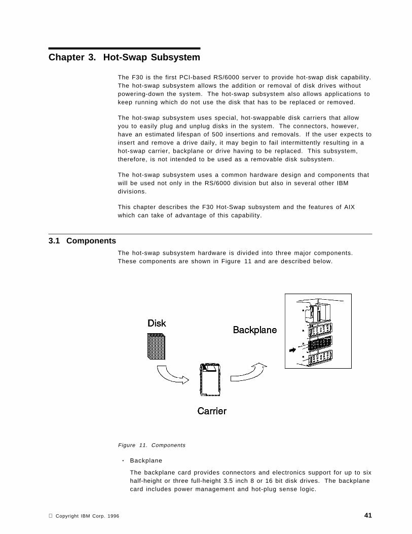
Chapter 3. Hot-Swap Subsystem
The F30 is the first PCI-based RS/6000 server to provide hot-swap disk capability.The hot-swap subsystem allows the addition or removal of disk drives withoutpowering-down the system. The hot-swap subsystem also allows applications tokeep running which do not use the disk that has to be replaced or removed.
The hot-swap subsystem uses special, hot-swappable disk carriers that allowyou to easily plug and unplug disks in the system. The connectors, however,have an estimated lifespan of 500 insertions and removals. If the user expects toinsert and remove a drive daily, it may begin to fail intermittently resulting in ahot-swap carrier, backplane or drive having to be replaced. This subsystem,therefore, is not intended to be used as a removable disk subsystem.
The hot-swap subsystem uses a common hardware design and components thatwill be used not only in the RS/6000 division but also in several other IBMdivisions.
This chapter describes the F30 Hot-Swap subsystem and the features of AIXwhich can take of advantage of this capability.
3.1 ComponentsThe hot-swap subsystem hardware is divided into three major components.These components are shown in Figure 11 and are described below.
Figure 11. Components
• Backplane
The backplane card provides connectors and electronics support for up to sixhalf-height or three full-height 3.5 inch 8 or 16 bit disk drives. The backplanecard includes power management and hot-plug sense logic.
Copyright IBM Corp. 1996 41

• Hot-Swap Disk Drive Carrier
The hot-swap SCSI disk drive carrier is a tray with built-in SCSI connectorsthat provide the interface between an industry standard SCSI 16-bit or 8-bitdisk drive and the 80-pin backplane connector.
The carrier includes two LEDs. One of the LEDs is used to indicate thestatus of the disk drive, and the other one is the power LED indicator for thecarrier.
Carriers are available for two drive types: narrow (half-height) and wide(full-height). The narrow carrier has a 50-pin drive connector. The widecarrier has a 68-pin drive connector. Both narrow and wide carriers havethe same connector at the rear of the hot-swappable carrier. The differentcarriers, therefore, can be installed into the same backplane card.
• Disk Drive
The following IBM disk drives have been tested within this environment:
− 1080 MB SCSI-2 disk drive:
− 1.1 GB SCSI-2 Fast/Wide disk drive
− 2.2 GB SCSI-2 Fast/Wide disk drive
− 4.5 GB SCSI-2 Fast/Wide disk drive
The hot-swap subsystem additionally requires a power source and a SCSI-2Fast/Wide SE adapter. The first backplane is connected to the first power supplyand to the integrated SCSI-2 Fast/Wide. Additional backplanes will be connectedto an additional SCSI-2 Fast/Wide PCI adapter and obtain their power from thesecond power supply.
3.1.1 BackplanesThe F30 can accommodate up to three backplanes each of which canaccommodate a maximum of six hot-swappable disks. The first backplane isinstalled in bank C (as shown in Figure 12 on page 43) and is supplied with theF30 as standard.
42 Introduction to PCI-Based RS/6000 Servers

Figure 12. Installing Hot-Swap
The second (feature #6421) and the third (feature #6422) backplanes are installedin banks D and E, respectively. The features, #6421 and #6422, contain all of thenecessary hardware to completely enable up to six hot-swap disks to beinstalled in the machine: the backplane, the power cable, the SCSI controller, theSCSI cable, and mounting hardware.
The F30 default configuration is to control bank C′s hot-swap disks and theremovable media devices (CD-ROM and so forth) with the integrated SCSI-2Fast/Wide controller. For improved performance, an optional PCI SCSI-2 SEFast/Wide adapter (feature #2408 or equivalent) can be installed to provide anindependent SCSI bus for Bank C′s disk drives. Feature #2446 provides thenecessary cable to control bank C ′s disks from this optional SCSI adapter.
3.1.2 Hot-Swap Bays and BanksFor a disk drive to be installed in one of the hot-swappable bays, the disk mustuse a hot-swappable carrier.
Each hot-swap bank contains six bays and can accommodate three full-heightdisk drives/carriers or six half-height disk drives/carriers. A combination of half-and full-height disk drives/carriers is possible.
Hot-swap bays are numbered from 1 to 6 from left to right. SCSI IDs rangingfrom 8 to 13 are assigned automatically from left to right. When disks areinstalled in the carriers, their SCSI ID jumpers have to be removed. Thehot-swap bay SCSI ID numbering is shown in Figure 13 on page 44.
Chapter 3. Hot-Swap Subsystem 43

Figure 13. Front Bays
3.2 InstallationThe requirements for installing hot-swap disk drives are not the same for allthree banks. A general requirement is that each hot-swap bank requires aseparate SCSI-2 adapter. In the case of the first bank, bank C in Figure 12 onpage 43, it uses the integrated SCSI-2 controller. Banks D and E require theinstallation of one additional backplane each. These additional backplanes usethe second power supply which is provided with the F30.
3.2.1 Accessing the Hot-Swap BanksTo access the hot-swap banks, you must first remove the front cover of yourmachine as shown in Figure 14 on page 45. To do this, refer to the chapter″Installing Options″ in the F30 User′s Guide; then look at the section titled″Removing the Front Covers Only.″ In the same order as this section describes,you should:
1. Open and remove the door.
2. Release the front cover latch.
3. Unlock the keylock.
4. Remove the front cover.
44 Introduction to PCI-Based RS/6000 Servers

.
Figure 14. Removing the Front Panel
This will provide you access to the hot-swap banks. If you only have onebackplane installed you will be able to add or remove up to six disks.
3.2.2 Installing Drives in Bank CThe backplane for bank C comes installed in the system. The SCSI IDs areautomatically assigned by the backplane for each bank. Therefore, no jumpersare required on the drives. If your disk drive has SCSI ID jumpers set, you mustremove them. Refer to the disk drive booklet provided with the system or withyour disk drive. Attaching SCSI address jumpers on the drive rather than usingthe automatic ID supplied by the backplane is not advised.
Each drive you plan to install in bank C must have the hot-swap carrier attached.It is recommended that you install the hard disk in the next unused position.
3.2.3 Installing Drives in Bank DTo install drives in bank D, you must first install a backplane in the back of thebank and an SCSI-2 Fast/Wide adapter in a spare PCI expansion slot. Theinstallation procedure is as follows:
1. Install a backplane in the bank.
2. Install an additional PCI SCSI-2 Fast/Wide adapter.
3. Connect the SCSI adapter to the backplane.
4. Connect the additional power supply to the backplane.
5. Install the hot-swap drive as you would for bank C.
Chapter 3. Hot-Swap Subsystem 45

3.2.4 Installing Drives in Bank EInstallation of drives in bank E is exactly the same as the procedure for installingdrives in bank D.
3.2.5 Disk CarriersThe disk carriers have two lights which enable you to determine the status of thedrive. Figure 15 shows a diagram of the lights and the spin down button, andTable 11 explains their meanings.
Figure 15. Disk Drive Light
During normal operation of AIX, both of the lights on the disk carrier will be on.If a drive is removed from the ODM, for example, by using:
rmdev -d -l hdiskx
the drive will spin down, and the amber light will go out.
Table 11. Status Lights
Light or Button Status Definition
Amber On Drive spinning
Off Drive not spinning
Green On Power On
Off Power Off
Blinking Power Off/Drive identify
Spin down Depressed Spin down drive and remove power
3.3 Using the Hot-Swap SubsystemHaving the hot-swap subsystem is very useful. As previously mentioned, itallows you to add, remove or replace disk drives without shutting down andpowering-off your system. There are, however, three levels at which you canuse the hot-swap subsystem.
46 Introduction to PCI-Based RS/6000 Servers

First, you can use the hot-swap subsystem to simply add and remove disk drivesfrom the system. You can buy and add new drives with ease, and these can bequickly configured into your system without affecting the users. You can alsoexport volume groups and remove the drives to put into other hot-swap systems,or you could remove a disk from a volume group and use the disk as an extradisk for another system.
Second, there is replacement usage. You may only have one system with thehot-swap capability and will only remove drives if they become faulty. In thisscenario, you can replace the drive without powering-off and shutting down thesystem. To enable the removal of the drive, the administrator will tell AIX thatthe disk is to be removed from the system. If the data on the disk can still beaccessed, the administrator can migrate the contents of the disk to another oneor back up the data on the disk. The disk will then be replaced, and using abackup of the data on this disk or by migrating the data back, the disk will bere-added to the system, and any data which was originally on the disk will berestored. In this scenario, where the data was not migrated, users who wereusing data on the drive will be affected. The users will be unable to access theirdata until a replacement drive has been fitted and the data restored.
The third usage of the hot-swap subsystem is mirroring, effectively giving thesubsystem RAID 0. Failures happen infrequently, but when the failures dohappen, they can cause havoc with your data. Using mirroring with the hot-swapsubsystem allows the system to carry on using data contained on a disk even ifthat disk fails since it will be able to use a mirror. If a disk fails, the disk can bereplaced and the new disk added to the system. A mirror can then be rebuiltwithout affecting AIX, the applications or the users. The subject of mirroring isdiscussed later in this chapter.
3.3.1 Adding a New Drive to a Live SystemWhen you install a new drive in the hot-swap subsystem, the amber light in thecarrier will flash and then go out. This indicates that the drive has beenidentified and is not spinning. At this point, AIX does not know that the drive ispresent in the system. To tell AIX that you have added a new drive, you can useSMIT or type:
cfgmgr
from the command line. Running this command will cause AIX to find the driveand spin it up. You will see the amber light come on at this point and will hearthe sound of the drive spinning up. Using the lspv command, you will be able tosee your new drive added. f the drive contains a volume group, you access itfrom your system by running:
importvg -y VGname hdiskx
Otherwise, you can add the disk to an existing volume group by using extendvgor create a new volume group by using smit mkvg.
3.3.2 Removing a Drive from a Live SystemTo be able to remove a hot-swap drive from the system without causingproblems, you will have to tell AIX that you are removing the drive.
Chapter 3. Hot-Swap Subsystem 47

3.3.2.1 Removing a Disk From an Existing Volume GroupIf you want to physically remove the disk and it belongs to an existing volumegroup, you would either remove the logical volumes which are present on thedisk (you can find out which logical volumes are present on a disk by using thelspv -l hdiskx command), or migrate the physical partitions from the disk toother disks in the same volume group. To remove a disk from an existingvolume group, you can use the following procedure:
1. Unmount all the filesystems on the disk if you are removing the logicalvolumes on the disk.
2. Remove all data from the drive by either removing the logical volumes or bymigrating the partitions on the disk to another disk in the same volumegroup. If you are removing the logical volumes, you may wish to back up thedata prior to removal.
3. Remove the drive from the volume group:
reducevg VGname hdiskx
4. Remove the device from the ODM:
rmdev -d -l hdiskx
When you run the rmdev command, the amber light on the drive will switchoff. If you run lspv, you will see that the disk is no longer defined to thesystem.
5. Physically remove the drive from the system.
3.3.2.2 Removing a Drive with its Own Volume GroupTo remove a drive which has its own volume group, you can use the followingprocedure:
1. Back up any data that you require from the volume group.
2. Unmount all the filesystems on the disk.
3. Varyoff the volume group by issuing:
varyoffvg VGname
4. Export the volume group by issuing:
exportvg VGname
5. Remove the device from the ODM by issuing:
rmdev -d -l hdiskx
6. Physically remove the device from the system.
The disk can easily be re-added to the system, and the volume group can beaccessed using the importvg command.
3.3.3 Replacing a Previously Defined DriveIf you add a disk drive which was already configured to the system and wasremoved using the procedures described above, then you can simply add thenew drive as described in 3.3.1, “Adding a New Drive to a Live System” onpage 47.
48 Introduction to PCI-Based RS/6000 Servers

3.3.3.1 Replacing a Previously Defined Drive into the Same BayIf a drive was physically removed without first being logically removed from theoperating system, then AIX may have problems. If there were no writes to thedisk after the removal of the disk, then there may be no requirement to run anycommands. If a write occurred after or during the removal of the drive and thedrive has been re-added, then you should perform the following:
1. Unmount all filesystems on the disk.
2. fsck -y filesystems on the disk.
3. Remount the filesystems on the disk.
3.3.3.2 Replacing a Previously Defined Drive into a Different BayIf you replace a drive into a different bay from the one from which it wasremoved, the one configured to the system by running the cfgmgr command, andyou didn′ t remove the device from the ODM before physically removing thedevice, then you will have to clear up the ODM because there will be a duplicateentry for the drive.
The following shows a scenario where there were three disks in the system andtwo volume groups on two separate disks. The disk belonging to testvg wasphysically removed without telling AIX.
Running the lspv command shows the three disks:
lspvhdisk0 00000000a641877c rootvghdisk1 00000000b0a645b0 testvghdisk2 00000000a6274604 None
hdisk1 was removed from the system before telling AIX. The disk was replacedinto a different bay than it was removed from. The cfgmgr command was run toconfigure the disk back into the system, and now lspv shows:
lspvhdisk0 00000000a641877c rootvghdisk1 00000000b0a645b0 testvghdisk2 00000000a6274604 Nonehdisk3 00000000b0a645b0 testvg
There are now two entries for the testvg volume group, both with the samephysical volume identifier. This is incorrect and can be cleared up byperforming the following:
1. Umount all filesystems in the testvg volume group.
2. varyoffvg testvg
3. exportvg testvg
At this point, you may get the following error which you can ignore:
0516-024 /usr/sbin/lqueryvg: Unable to open physical volume.Either PV was not configured or could not be opened. Rundiagnostics.
Running lspv now shows:
Chapter 3. Hot-Swap Subsystem 49

lspvhdisk0 00000000a641877c rootvghdisk1 00000000b0a645b0 Nonehdisk2 00000000a6274604 Nonehdisk3 00000000b0a645b0 None
4. rmdev -d -l hdisk1
5. rmdev -d -l hdisk3
6. cfgmgr
Running lspv now shows the correct disks:
lspvhdisk0 00000000a641877c rootvghdisk1 00000000b0a645b0 Nonehdisk2 00000000a6274604 None
7. importvg -y testvg hdisk1
8. Mount all the filesystems. You may have to run fsck -y on the filesystemsfirst if they were written to while the disk was removed.
3.3.4 MirroringMirroring disks has been discussed at great detail in many publications and inInfoExplorer. Here, we will explain an outline of the process you will need totake to use mirroring. Mirroring will take maximum advantage of the hot-swapsubsystem.
The hot-swap subsystem will mean that AIX will have to be explicitly told aboutthe removal and addition of disks. In a normal AIX environment the systemwould have been shut down and powered-off. The system would then recognizethe removal or addition of disks.
3.3.4.1 Removing and Adding a Mirrored DiskIf you want to remove a disk which is a mirror of other disks in its volume group,you can either remove the logical volume ′s copies which are on the disk andfollow the procedure outlined in 3.3.2.1, “Removing a Disk From an ExistingVolume Group” on page 48, or you can remove the disk without telling AIX. Ifyou choose to remove the disk without telling AIX, you should perform thefollowing when you re-add the disk:
1. Unmount all the filesystems which are mirrored on the disk.
2. Change the state of the disk in the volume group to active:
chpv -v -r hdiskxchpv -v -a hdiskx
3. Synchronize all the partitions on the disk from their mirrors:
syncvg -v VGname
4. Remount all the filesystems which are mirrored on the disk.
This will ensure that AIX correctly knows about the disk being re-added and thatall the partitions are correctly synchronized.
If the disk is part of the root volume group and the filesystems which are on thedisk can′ t be unmounted, then you can either wait for a reboot of the system orremove the disk from the volume group, and then re-add the disk by performingthe following:
50 Introduction to PCI-Based RS/6000 Servers

1. Remove all the mirrored copies from the mirrored disk (for example, if wehad a logical volume called lv00, there were a total of two copies of thelogical volume and the disk which was removed was hdiskx):
rmlvcopy lv00 1 hdiskx
2. Reduce the rootvg to remove the disk:
reducevg rootvg hdiskx
3. Remove the device from the ODM:
rmdev -d -l hdiskx
4. Insert the new drive.
5. Configure it to the system:
cfgmgr
6. Extend the root volume group to this disk:
extendvg rootvg hdiskx
7. Recreate the mirrors on the disk, for example:
mklvcopy lv00 2 hdiskx
Chapter 3. Hot-Swap Subsystem 51

52 Introduction to PCI-Based RS/6000 Servers

Chapter 4. Boot Support and Firmware
The PCI RS/6000 Entry Server systems are based on the PowerPC ReferencePlatform Specification (PReP); thus, in contrast to the microchannel-basedRS/6000 systems systems, their hardware is not bound to a specific operatingsystem.
In order to separate the hardware from the software, an abstraction layer,defined in PReP, is required. The abstraction layer is called Software ROS(Read-Only Storage) and includes the following two components:
BTAS (Boot Time Abstraction Software) Abstracts the hardware that a platform′sboot program (for example, firmware) uses at boot time. It alsoabstracts the hardware that the operating system loader uses to loadan operating system.
RTAS (Run-Time Abstraction Software) A collection of data and software thatabstracts hardware from the operating system kernel
For more information on the PReP-specific abstraction layer, refer to theManaging AIX V4 on PCI-Based RS/6000 Workstations redbook, or to thePowerPC Reference Platform Specification.
Figure 16. Boot Structure on PCI-Based RS/6000 Systems and Microchannel-BasedRS/6000 Systems
Figure 16 shows the components involved in booting a PCI-based RS/6000system compared to the microchannel-based RS/6000 systems.
Since on the microchannel-based RS/6000 systems the only operating systemsupported is AIX, the firmware (also called system ROS on those machines)builds the IPL control block required by the AIX boot image using the structuredefined by AIX.
On PCI-based RS/6000 systems, the firmware initializes the hardware in ageneric way to allow any PReP-compatible operating system to boot on thesystem. The hardware initialization data is passed to the abstraction layer
Copyright IBM Corp. 1996 53

software via residual data. In the case of AIX, the abstraction layer builds therequired IPL control block before the AIX boot image is loaded.
In the first part of this chapter, we will explain the components involved in theboot process:
• Boot record
• Firmware
• Software ROS
• NVRAM
• Boot image
Then, we will describe the boot process performed by the firmware, and finallywe will give an introduction to the System Management Services (SMS)programs.
4.1 Boot RecordOn microchannel-based RS/6000 systems machines, the entire disk is dedicatedto the AIX operating system. Block 0 of the disk is expected to contain theboot-record.
Figure 17. Hardfile Layout on Microchannel-Based RS/6000 Systems
The hardfile layout on PCI-based RS/6000 systems is designed to allowtransportable media between various processor types (for example, Intel andPowerPC 60x) the hardfile layout is similar as now found on a system runningDOS or OS/2. It implements the concept of disk partitions as specified in thePReP Specification. Following this architecture, the AIX disk image would residein one of those partitions, as shown in Figure 18.
Figure 18. Hardfile Layout on PReP Specification
54 Introduction to PCI-Based RS/6000 Servers

Different partitions could hold different operating systems or different versions ofAIX. The user could be able to choose the operating system to boot, as in“dualboot” on OS/2 and DOS.
The problem with this implementation is that both the Master boot record andthe AIX boot record are required to start on disk block 0. To satisfy thisrequirement, the boot record on PCI-based RS/6000 systems is a combination ofboth, as shown in Figure 19.
Figure 19. Hardfile Layout on Microchannel-Based RS/6000 Systems
Note
Partitioned disks are not supported in the current release of AIX. Currently,AIX requires all disks used by AIX to be dedicated disks.
4.2 Boot Components Specifically for AIX 4 on PCI-Based RS/6000 SystemsThe firmware on microchannel-based RS/6000 systems is sophisticated enoughto:
• Find the boot device
• Build the IPL control Block required by the AIX boot image
• Load the AIX boot image from the boot device
• Pass control to the boot image
On PCI-based RS/6000 systems, however, the firmware is simple and generic,independent of the operating system; therefore it does not build the IPL controlblock for AIX, but:
• Finds the boot device
• Locates the operating system bootstrap code
• Passes control to the bootstrap code
regardless which operating system is booting.
In order to create the IPL control block and perform the initialization required bythe AIX boot image, a new, intermediary software component has to be added tothe boot process on PCI-based RS/6000 systems, the Software ROS.
The boot process on PCI-based RS/6000 systems includes the following threemajor components:
1. Firmware
Chapter 4. Boot Support and Firmware 55
2. Software ROS for AIX
3. AIX boot image
4.2.1 FirmwareThe firmware is the first code executed when the machine is powered-on.Firmware takes the system from a power-on state to a state where an operatingsystem loader is in memory, ready for execution. Firmware is typically stored inread-only memory (ROM) or in programmable read-only memory (PROM).
The firmware on PCI-based RS/6000 systems performs the following steps:
1. Initializes processor registers
2. Initializes the memory controller
3. Establishes an active RAM area
4. Copies decompressed code to RAM
5. Decompresses compressed area into RAM
6. Establishes execution environment (stacks, and so on)
7. Initializes the console
8. Displays graphic-logo on console
9. Initializes individual subsystems
10. Locates and loads the operating system′s boot code
The PCI-based RS/6000 system′s firmware also provides functions that werealready incorporated in the microchannel-based RS/6000 systems firmware. Oneof them is Power-On Self Test (POST). The POST checks basic hardware, suchas processor, native I/O and system memory. It makes a list of the workinghardware it recognizes.
When booting, the firmware obtains the boot device list maintained in NVRAMand tries to locate the first valid boot device that has valid boot image on it (thisis determined by reading the first 512 bytes on a device). When a valid bootimage has been found, it is loaded into memory, and firmware passes control toit. The firmware does not have to be aware of the type of code it loads, whetherthis code is Software ROS or the kernel of an operation system. In case of theAIX, it is Software ROS.
4.2.2 Software ROS for AIXSoftware ROS is an intermediary software that implements the Boot-TimeAbstraction Software (BTAS) specified in the PReP specification (see Chapter 4,“Boot Support and Firmware” on page 53). This software is the bootstrap codeloaded by the firmware. Software ROS starts by copying the contents of NVRAMinto system memory.
When the firmware executes after IPL, it scans the system for basic workinghardware and stores the information in the memory as residual data. Residualdata is used by conventional firmware to pass system information collected bythe firmware to the operating system, in our case to Software ROS. It is storedin Little-Endian format and must be converted to Big-Endian format as requiredby AIX.
56 Introduction to PCI-Based RS/6000 Servers

Software ROS converts the data into Big-Endian format and handles all thedifferences in formats and structures so that the AIX kernel will be able to usethis data at a later time. Prior to locating the AIX boot image, Software ROSupdates the IPL control block with the address of the converted residual data.
4.2.2.1 NVRAM Initialization by Software ROSBecause of the differences in size and usage conventions of the NVRAM on thePCI-based RS/6000 systems, it is necessary for Software ROS to initialize theNVRAM image used by the AIX operating system. ROS allocates a section ofmemory at the end of the IPL control block to use as the NVRAM buffer.Software ROS copies and reformats the information contained in the physicalNVRAM into this buffer. The respective data is updated in the IPL control blockto reflect the size and location of the NVRAM buffer.
4.2.2.2 Construction of the IPL Control BlockOn taking control of the system, Software ROS builds an IPL control block that iscompatible with AIX. The input for this control block comes from three differentsources:
Defined values Hardware-specific information that is model dependent (forexample, number of slots)
Computed values Information which is taken by calling query routines against theplatform for values (for example, amount of L2 cache)
Residual information Information which is made available by the firmware asresidual data (for example, device names)
4.2.2.3 Locating and Transferring Control to the AIX Boot ImageSoftware ROS uses the boot record to locate the AIX boot image. Whatevercode is at the beginning of the AIX boot image, Software ROS passes control toit. First, it verifies whether the boot image is compressed or not (remember thatthis is an option supported by the AIX V4 bosboot command).
Before passing control to the boot image, Software ROS creates a relocationmodule immediately preceding the IPL control block in high memory. Thisrelocator is used to move the loaded boot image to begin at address 0, asrequired by AIX.
4.2.3 Non-Volatile RAM (NVRAM)This memory is backed up with a battery and stores system configuration datafor use by the firmware and the different operating systems that can be run onthe machine. The NVRAM is located on the ISA bus together with the Real-TimeClock (RTC) and, of course, the battery. On microchannel-based RS/6000systems, this memory is mapped directly into the memory address map and canbe accessed by the operating system directly. On PCI-based RS/6000 systems,reading and writing to NVRAM requires that the address be gated into a registerpair and the data accessed from it one byte at a time.
The NVRAM is divided into three major areas:
• Global Environment Area (GEArea)
• Operating System Area (OSArea)
• Configuration data for non-native ISA devices area
Chapter 4. Boot Support and Firmware 57

Additionally, NVRAM contains a header that describes the location and length ofthese areas.
Figure 20. NVRAM Layout
GEArea Contains definitions of global environment variables which can beupdated and used by different operating systems. Global variablesare used mainly by the firmware for cached data or by operatingsystems to communicate with the firmware.
OSArea The data in this area is preserved between boots of the sameoperating system only; otherwise the data can be overwritten.
Configuration data for non-native devices area Stores data for ISA devices whichare not integrated on the system board. The data must berepresented in the format of the compressed Plug and Playconfiguration packet. Data in this area is stored and used by theoperating system. The firmware passes this configuration data to theoperating system by using residual data. This area is located at thetail of NVRAM and grows toward lower addresses.
4.3 Boot ImageThe AIX boot image is loaded by the Software ROS. It consists of the followingcomponents:
• An AIX kernel
• The RAM file system
• Base customized device information
AIX Version 4 provides support for the following three different RS/6000platforms:
Table 12. Platform Types
Name Description
rs6k Microchannel-Based RS/6000 Systems
rs6ksmp Symmetric Multi-Processor RS/6000systems
rspc PCI-based RS/6000 systems
58 Introduction to PCI-Based RS/6000 Servers

The AIX boot image used in each of the above platforms is platform-specific. Tocreate platform-specific boot images, AIX provides support for the following twoissues:
• Recognition of the platform type -
The given platform is specified in the IPL control block built by SoftwareROS. The boot utility command, bootinfo -T, inspects the IPL control blockand prints the platform type to the standard output.
• Specifying the platform type -
With the command bosboot -T, you can generate the boot image for thetarget platform. If the platform type is not specified, this command defaultsto the current platform type that the system is running on.
4.3.1 Platform-Specific ComponentsThe AIX boot image is created using the bosboot command. In AIX Version 4.1,however, this boot image is specific to one of the supported platformtypes. The following platform-specific components are required to create the AIXboot image.
• Base Proto and Proto Extension Files
• RAM Filesystem
• Object Data Manager (ODM) Predefined Database
4.3.1.1 Base Proto and Proto Extension FilesBase Proto and Proto Extension files are used to create the prototype filesneeded for building the RAM file system used during the boot. The prototypefiles include device configuration methods and device drivers that are specific toa given machine′s device configuration.
The bosboot command builds the prototype file by dynamically combining theBase Proto file with proto extensions to include the installation methods anddrivers.
Figure 21. Relation Map of Base Proto and Proto Extension Files
Chapter 4. Boot Support and Firmware 59

Base Proto Files: The Base Proto files are platform specific. They containlibraries, non-device-related commands and ODM data files relevant to a specificplatform. They are named with the platform type as their prefix:
• For microchannel-based RS/6000 systems:
rs6k.disk.proto, rs6k.tape.proto, rs6k.cd.proto, rs6k.tok.proto,rs6k.ent.proto, rs6k.fddi.proto
• For SMP systems:
rs6ksmp.disk.proto, rs6ksmp.tape.proto, rs6ksmp.cd.proto,rs6ksmp.fddi.proto, rs6ksmp.tok.proto, rs6ksmp.ent.proto
• For PCI-based RS/6000 systems:
rspc.disk,proto, rspc.cd.proto, rspc.tape.proto, rspc.tok.proto,rspc.ent.proto
Note!
The rspc.tape.proto proto file is new in AIX Version 4.1.4 and allows thecreation of a bootable tape on PCI-based RS/6000 systems.
Proto Extension Files: Combined with the Base Proto files, Proto Extension filesare also used for dynamically creating the prototype file. The platform-specificinformation is incorporated so that only those extension files relevant to thegiven platform type are used. However, some of the extension files are used formore than one platform, and some are used for only one specific platform.
To specify which platform needs which types of extension files, they are placedin groups specified as part of their file names. The platform-specific informationfor the proto extension file groups are maintained in a configuration file whichhas a .pcfg extension. The .pcfg file is prefixed with the platform type, and itcontains the list of device groups which are valid for a given platform.
Proto Extension Configuration File
As an example, for the PCI-based RS/6000 platform, the file is calledrspc.pcfg and is located in the directory /usr/lib/boot/protoext.
4.3.1.2 RAM File SystemWhen the bosboot command is running, it determines the type of platform and theboot device for the boot image. It builds the prototype file based on theinformation provided by the base proto and proto extension files(4.3.1.1, “BaseProto and Proto Extension Files” on page 59). Once the prototype file is built,the boot image generation proceeds as in AIX Version 3, where the RAM filesystem is first created, and put together with the stripped kernel image.
The structure of the RAM file system is defined in the base proto files. The RAMfile system must contain all data, commands, libraries, and ODM objectsrequired during the boot and before the real file systems are mounted from disk,network or another device.
60 Introduction to PCI-Based RS/6000 Servers

4.3.1.3 ODM Predefined DatabaseIn AIX Version 3, the Device Configuration Database consists of customized andpredefined objects for all devices supported by AIX. Predefined objectscontribute a major portion of the device database and contain information aboutall possible types of devices that can be defined for the system. However, thecomplete Predefined Database is not required, nor is it desirable due to its largesize. During boot or installation, only subsets of device information are needed.The problem is that these subsets are different, depending on the boot andinstallation devices and the different phases of the boot process.
In AIX Version 4, the Device Predefined Database is customized to theconfiguration of the given system, thus reducing the overall size of the DeviceConfiguration Database. The whole Predefined Database on a given system issmall enough to fit into the boot image, providing consistent device informationfor boot and install across different devices and eliminating the need for subsetsand stanzas files.
ODM Predefined Database
The ODM Predefined Database (PdDv and PdAt) on PCI-based RS/6000systems contains definitions and attributes relevant to this platform only.
4.3.2 Structure of the AIX Boot image on PCI-Based RS/6000 SystemsThe AIX boot image on PCI-based RS/6000 systems is a combination of aPReP-compliant partition image and a standard AIX Version 4 boot image, asshown in Figure 22.
Figure 22. Boot Image Layout on PCI-Based RS/6000 Systems
When the system is booted, the firmware loads the first sector containing theMaster Partition Header, which includes the AIX boot record and the partit iontable. The Partition Entry Offset and the Length of Partition In Sectors, extractedfrom the first partition entry in the table, indicates where to find the next partitionto be loaded and the size of the partition, respectively. This partition containsthe Software ROS code.
Chapter 4. Boot Support and Firmware 61

After Software ROS takes control and performs the appropriate initialization, itlocates the AIX Version 4 boot image and loads it at address zero as required byAIX.
Figure 23 shows the structure of the RSPC-style boot image. Areas Reserved 1and Reserved 2 are reserved for padding purposes.
Figure 23. Structure of the Boot Image on PCI-Based RS/6000 Systems
4.3.3 Boot Image Creation on PCI-Based RS/6000 SystemsTo support boot image creation for PCI-based RS/6000 systems, severalcommands involved within the boot support process were changed in AIXVersion 4. The changes were limited to a minimum, and the main idea is to stilluse the bosboot command to generate a boot image. Some options have beenchanged in bosboot to support the new platforms (SMP and RSPC systems). Infact, most of the changes are hidden to the user. The command bosboot -a willcreate a boot image for the platform type of the system running the command.
Cross Boot Image
Creation of boot images for a different target platform is possible on serverswhich have installed the required base proto and proto extension files andthe predefined database for the target platform.
When using the Network Installation Manager (NIM), all the devices ′ softwarepackages are installed, and NIM handles different boot images according tothe target platform type.
Figure 24 on page 63 shows the components and commands involved within theprocess of creating the AIX Version 4 boot image.
62 Introduction to PCI-Based RS/6000 Servers

Figure 24. AIX Version 4 Boot Image Creation
When the bosboot command is started, it creates a RAM file system and calls themkboot command to create the boot image as is normal for an AIX system. Upondetection of a RSPC system, the bosboot command calls the mkmboot routine toencapsulate the AIX Version 4 boot image into the RSPC-style boot image.
4.4 Understanding the FirmwareThe firmware is the first code to execute when the machine is powered-on. Thiscode resides on the hardware, and it is coded in the factory.
The firmware uses the console and the speaker as means to communicate theresults of certain tests. By default, the firmware uses the serial port S1 todisplay logos, messages and errors. In case a supported graphics adapter isinstalled in the machine, the firmware will redirect the output to this adapterinstead of the serial port.
The firmware is organized into three major sections:
Boot Block Receives control at power-on and is able to perform a soft firmwarerecovery from diskette when necessary
Chapter 4. Boot Support and Firmware 63

Firmware Core Brings the system up to where the compressed image has beendecompressed and running
Virtual Disk Contains the firmware modules required to support each hardwaresubsystem
4.4.1 Firmware Boot SequenceThis section describes the firmware booting process on PCI-based RS/6000. Thisis also shown on Figure 25.
Figure 25. Firmware Boot Sequence
When the system is powered-on, the hardware passes control to the storageaddress 0xfff00100, the firmware entry point.
1. The firmware ′s first task is to perform a processor POST (Power-On SelfTest).
An uncompressed instruction resides on the entry point of the firmware. Ifthe processor fails to execute this branch instruction, the next instruction isexecuted.
• If it fails, the system stops.
2. The 60x registers are initialized.
• If it fails, the system stops and appears to be doing nothing, but coolingfans might be observed running.
3. The firmware initializes the memory controller, and 2 KB of good memory isfound.
• If it fails, the hard file LED is turned on, and the system stops.
4. A short beep is given on the speaker.
5. A Cyclic Redundancy Check (CRC) is performed on the compressedfirmware.
64 Introduction to PCI-Based RS/6000 Servers

• If the firmware is corrupted, run the firmware recovery procedure (see4.4.4, “Firmware Recovery” on page 68).
6. The firmware core copies a particular part of the firmware code into thesmall amount of memory. This firmware code runs the memory POST andconfigures 3 MB of good memory.
• If it fails, the hard file LED is turned on, and the system stops.
Passed Critical Phase
After 3 MB of good memory has been successfully configured, the systemwill not stop. Any subsequent failures will be logged and displayed as8-digit error numbers.
7. The compressed firmware is copied into the larger amount of good memory(3 MB) and uncompress.
8. A new C environment is set up in the larger area, along with a user stack, aninterrupt stack, a debugger stack, and a TOC (Table of Contents) pointer.
9. The individual subsystems are initialized:
• The Virtual Disk is brought online
• NVRAM initialization
• PCI set up
• Interrupts initialization
• Real-Time Clock initialization
• Keyboard/mouse controller initialization
• Password initialization
• Debugger initialization
10. The Virtual Disk (VDISK) file system is loaded and initialized.
11. All device drives from the VDISK file system are loaded.
• VIDEO: initialize ASCII terminal and/or VGA adapter
− Initialize Async Console Support (ASCII terminal S1 serial port)− Execute the VGA adapter POST. If there is an error, then one long
beep and one short beep is sounded on the speaker.
• Display the “brand” logo on the graphic console or a POST indicator onan ASCII terminal.
• Keyboard icon appears; initialize the keyboard and mouse.
• The window for pressing F1 (GUI SMS interface) or F4 (ASCII) keys isnow open.
• The diskette icon appears; initialize the controller.
• Extended memory icon appears; test the reminder of memory. Memorymodules failures are displayed with the 8-digit error code 00020000.
• The SCSI icon appears; initialize the adapters: SCSI, ethernet, pci_c970,trpci, tcpip, and initialize network when present.
• The last icon is the boot disk icon.
12. One long beep is sounded on the speaker.
Chapter 4. Boot Support and Firmware 65

13. If Power-On Password or Privileged Access Password options are in effect,then the Password screen appears. There are three attempts to the correctpassword; otherwise the 8-digit error code 00016005 is displayed, and thesystem stops. The only way to recover the system is to power-off andpower-on again.
4.4.2 Firmware PasswordsThe user can limit access to the system by using passwords. The passwordscan be up to eight characters long and are stored in NVRAM. There are threecategories of restricted access:
• Power-On password
• Privileged Access password
• Unattended start mode
Do Not Have the Password?
In case you don′ t have a machine′s password, the only way to get access tothe system is by removing the system′s battery. You must be aware that thisprocedure will erase all firmware configuration data maintained in NVRAM,such as the error log and any configured IP addresses.
4.4.2.1 Power-On Password (POP)When the system is powered on, it checks whether a power-on (POP) passwordis present. If there is one present and the “unattended start mode” is NOT set, itmeans the machine ′s owner does not want the system to be used unless thePOP password is supplied. In this case, the system will prompt for the POPpassword. The user is given three attempts to enter the correct password. If theuser fails to supply the correct password, the system will go into a “hung” stateand must be powered off before continuing.
4.4.2.2 Privileged Access Password - PAPThe Privileged Access password is used to limit access to the SystemManagement Services (SMS) programs (also called the Supervisory PasswordWhen the user presses one of the keys to access SMS, the system will check tosee if a Privileged Access password exists; if it does, the user is prompted toenter the Privileged Access password. The user is given three attempts tosupply the correct password. If the user fails to do so, the system will go into a“hung” state and must be powered off before continuing.
4.4.2.3 Unattended Start ModeTo use this mode, a power-on password must be previously specified. Ifunattended start mode is enabled, the system will boot from the defined bootdevice without requiring the user to enter the power-on password. While thesystem can be booted without entering the POP password, the keyboardcontroller will be programmed to lock up until the POP password is provided.This mode is ideal for servers that run unattended. After an electrical powerfailure, for example, the operating system will be rebooted without waiting for auser to enter the power-on password.
66 Introduction to PCI-Based RS/6000 Servers

4.4.3 Firmware Flash UpdateThere are several situations where a firmware flash update may be required.For example, after a field EC (engineering change) or to provide firmwaresupport for a new adapter.
The firmware flash update can be performed by the user in Normal mode or bythe system in Recovery mode. The default is the Normal mode updateperformed by the user from the SMS Tools (Utilities in the ASCII version) menu.Messages and errors are communicated through the menu pop-up interface.
The Recovery mode update is executed automatically when a bad firmwareimage is detected during early system initialization (see 4.4.1, “Firmware BootSequence” on page 64). In this mode, most messages and errors aresuppressed; fatal errors are displayed in a serial-interface-compatible format.
To start a firmware update, you have to perform the following steps:
1. Access SMS.
2. Select the Tools menu (Utilities in the ASCII version).
3. Select the Update icon (Update System Firmware on ASCII).
Before starting the firmware update process, the system will ask you if youwant to create a firmware recovery diskette. It is recommended to create therecovery diskette, unless you have created it already. To create therecovery diskette, insert a blank DOS-formatted diskette.
4. After the recovery diskette has been successfully created, follow theinstructions to update the firmware.
To update the firmware, the system searches the diskette drive for a flashupdate file with the extension .IMG. If found, the file is loaded. This file is acomposite image. It does not contain the entire firmware; thus, when thefirmware is updated, only the sectors contained in the .IMG file are programmed.
Once loaded, the image is examined to ensure it is a valid firmware image.Flash table/system ID structure, file length and the Cycle Redundancy Check(CRC) are verified. If we have a valid image, the Vital Product Data (VPD)information is duplicated in the recovery block (for recovery purposes in casethe image is corrupted) and also merged with the composite image.
Now, the update routine starts programming the firmware sectors to be updated.
Attention
A system power-off in this section of code will result in a corrupted flashROM.
Notice that because only the composite image sectors are erased andreprogrammed, those sectors are the only ones that could be corrupted. Sincethe recovery block is protected in Normal mode and Recovery mode, the systemcan still be restored by using the recovery diskette. A system power-down at thewrong time could result in a completely corrupted flash ROM and a dead system.
Chapter 4. Boot Support and Firmware 67
4.4.4 Firmware RecoveryDuring the firmware boot process, one of the first tasks is to verify the CycleRedundancy Check (CRC) of the firmware code. If the update portion of thefirmware has a CRC miscompare (is corrupted), you will see the followingsymptoms:
• One short beep will be sounded on the speaker.
• The hard disk LED will blink continuously.
• The diskette drive LED is selected or blinking, waiting for a diskette to beinserted.
• The display or tty is blank.
Recovery Procedure: To rewrite the Flash memory, you will need a firmwarerecovery diskette .
Note
The recovery diskette must be made in advance at the customer locationusing the ″Update System Firmware″ utility provided with the SystemManagement Services (SMS) program.
If you have a firmware recovery diskette, perform the following steps:
1. Insert the firmware recovery diskette into the diskette drive. The disketteLED should turn on while data is being copied into memory.
2. The hard file LED should stop blinking. The system will retry forever whensomething is wrong.
3. The system will reboot the machine when the recovery is successful.
The firmware flash routine performs some general clean-up and reboots thesystem. Once the system is rebooted, the new flash image is active andexecuted.
4.4.5 Power-On Self Test (POST)The following POST tests are performed by the firmware on PCI-based RS/6000systems:
4.4.5.1 Processor POSTThe firmware tests the processor very briefly. If there is a failure, the systemwill stop, and the initial beep of the speaker will not be heard.
4.4.5.2 Memory DIMM and L2 Cache POSTThe firmware RAM POST tests all the memory; it is done in segments. After theinitial short beep, if the system stops with the hard file indicator on solid, this isthe indication that no memory was found. If some memory is found, then a good2 KB continuous segment is sought. If the 2 KB segment cannot be found, thesystem stops with the hard file indicator on solid.
The L2 cache is tested. If it fails, there will be a momentary indication when thedisplay becomes available. The error is also written to the Error Log. Duringthe system initialization when icons are being displayed for the individual
68 Introduction to PCI-Based RS/6000 Servers

subsystems, one of the icons will be the memory icon. During the display of thisicon, an 8-digit error code will be displayed if the L2 cache is not fully functional.
The remainder of memory is also tested, and if a failure is detected, an 8-digiterror code is posted. This error indicates which Dual Inline Memory Module(DIMM) slot is at fault. The basic algorithm for the system memory configurationis as follows:
1. Query each memory slot to see if there is a memory DIMM installed.
• If yes, determine its size. Identify each DIMM as IBM or non-IBM, ECC orparity. This is done by querying special identification registers in theDIMMs themselves.
• If the DIMM could not be identified, display the memory slot number aswell as a warning saying that a DIMM could not be identified. Proceedwith the next DIMM.
2. Test the DIMM.
• If this is an IBM DIMM and it passes the test, make it available and addits size to the “available memory” quantity. If it doesn′ t pass the test,keep the DIMM out of the system configuration, and display a warning onthe screen reporting the faulty DIMM slot number.
• If this is a non-IBM DIMM and passes the test, make it available, and addits size to the “available memory” quantity. In addition, display amessage on the screen reporting that a non-supported, non-IBM memoryDIMM has been found, tested and correctly configured. If the DIMMdoesn ′ t pass the test, display a warning on the screen reporting that anon-IBM memory module was found and failed to pass the test.
3. Proceed with the next DIMM.
At the end of this process, the system will have available all the memory it couldconfigure (IBM or not).
4.4.5.3 Graphics Adapter POSTThe firmware does test the graphics adapter but not the display. The system willgive a speaker beep sequence when the graphics adapter is found to benon-functional. The beep sequence is a one long beep, followed by one shortbeep. The error is logged, and the system boot continues.
4.4.5.4 Keyboard and Mouse Controller POSTThe keyboard/mouse controller has a built-in Power-On Self Test, and thefirmware checks the result. If an error is detected, an 8-digit error code isdisplayed; the error is written to the Error Log, and the system continues.
4.4.5.5 SCSI Subsystem POSTThe SCSI POST opens the adapter and runs several test scripts which check andexercise the various functions related to the chips on the integrated SCSIadapter, such as DMA, simulate mailbox commands, and so on. If an error isdetected, an 8-digit error code is displayed; the error is written to the Error Log,and the system continues.
Chapter 4. Boot Support and Firmware 69

Note
The 8-digit POST error codes are listed and described in the User′s Guidemanual for the corresponding PCI-based RS/6000 system.
4.5 LCD PanelThe LCD panel is part of the PCI-based RS/6000 hardware. During the bootprocess the system will display 3-digit codes on the left of the top row on theLCD panel. The intended use of the 3-digit codes is to assure the observer thatthe firmware is operational after power-on and before information appears onthe console display.
Table 13 shows the most important LCD codes. All possible codes aredocumented in the Service Guide manual for the corresponding PCI-basedRS/6000 server.
Table 13. Checkpoint Codes on the LCD Panel
Code(Hex)
Description
F08 Run recovery block base, test 2 KB, then set the stack
F09 Copy CRC verification code to RAM
F09 Turn on cache
F0B Flush cache
F19 Initialize base memory, stack
F1A Copy uncompressed recovery block code to RAM
F1F Branch to high-level control routine
F20 Initialize I/O system
F22 No memory found
F25 Unsupported DIMM detected
F4B CPU over temperature or bad system board
F54 Fan fail warning
F60 Initialize keyboard/mouse controller and password
F61 Extended memory init ialization command
F71 Stating whether CMOS contents are valid
F74 CMOS initialization
F7A NVRAM initialization
F91 Low-level initialize VDISK file system
FA0 Start resident monitor, run V: autoexec.6md; initialize varioussubsystems: video, keyboard/mouse, extended memory, diskette, SCSI,and so on.
FA5 ASCII terminal initialization
FCE No operating system boot, exit normal boot sequence
FD0 Start of boot sequence
Note: See Appendix A, “Firmware Checkpoint Three-Digit Codes” on page 185 formore information on LCD codes.
70 Introduction to PCI-Based RS/6000 Servers

4.6 System Management Service (SMS)The SMS programs make it possible for you to view information about yourcomputer, run memory tests and set the device from which the server will boot.
By default, the firmware uses the serial port S1 to display logos, messages,errors, and also as the interface to the SMS programs. If a supported graphicsadapter is installed in the machine, the firmware will redirect the output to thisadapter instead of the serial port. It means, if you have installed a graphicsadapter but you want to use an ASCII terminal attached to serial port S1 as theconsole for the SMS programs, then you will have to remove the graphicsadapter first.
The SMS programs provide two types of interfaces: a graphical user interfacewhich can be used on a graphical display and an ASCII interface which can beused either on an ASCII terminal or on a graphical display.
Note: The ASCII interface provides more functions than the graphical interface.
To start the programs:
1. Turn on or shut down and restart the computer.
2. When the first screen appears, press the F1 key to use the GUI interface. Touse the ASCII interface, press the F4 key. On an ASCII terminal, you canpress either the number 1 or the number 4 key.
Note: You must press above listed keys before the last indicator appears.
4.6.1 SMS Graphical Main MenuThe graphical System Management Menu offers the following services:
Start Up Allows you to define a customized boot list which defines thesequence in which devices are searched by the system for a bootableimage.
Test The only test supported here is the memory test. Testing otherdevices can be performed by using the diagnostics tools as explainedin Chapter 8, “Diagnostics Support” on page 145.
Tools Provides several tools to set and remove passwords, to set theunattended start mode, to update the firmware, to set the IPaddresses for network booting, and other utilities.
4.6.2 SMS ASCII Main MenuThe ASCII version of the System Management Services includes an additionalfunction not found in the graphical version, support for the following languages:
• English• French• German• Italian• Spanish• Swedish
All menus and options, as well as the button titles, have been translated.
Chapter 4. Boot Support and Firmware 71

4.6.3 Start-Up MenuThe corresponding menu to the graphical Start Up menu in the ASCII SMSversion is the Select Boot Devices menu. The Start Up menu enables you todefine a custom boot list which determines the order in which devices aresearched by the operating system for a bootable image.
When this menu shows up, the current boot-order list is displayed. The Defaulticon can be used to restore the default settings, or the Select icon can be usedto configure a new boot-order list. The default settings are:
1. Diskette drive
2. CD-ROM drive
3. Hard disk drive
4. Network (if any network adapter installed)
To configure a device as a boot device, you can use the mouse and click on thedevice; or use the arrow keys to highlight the device, and press the Spacebar toselect it. A number indicating the order of the startup sequence will appear onthe device.
To cancel the configured selections, the Cancel icon can be used.
The ASCII interface offers an additional function (option 7. Boot Other Device)which can be use to boot directly from the specified device without having tochange the boot-order list.
4.6.4 Test MenuThe corresponding menu to the graphical Test menu in the ASCII SMS version isthe Test the Computer menu. The Test menu allows you to test the systemmemory.
To begin the test, select the Test icon. The Loop Test icon, when selected,allows the memory to be tested in a continuous loop. The test can be stoppedby pressing the S key. If a problem is detected during testing, an error codesimilar to the one below will be displayed:
00020000
4.6.5 Tools MenuThe corresponding menu to the graphical Tools menu in the ASCII SMS versionis the Utilities menu. The Tools menu contains the following utilities:
Power-On Allows you to set or remove a power-on password.
Super Allows you to set or remove a Privileged Access password.Privileged Access means access to the System Management Servicesprogram.
Remote On When enabled, the system will boot from the defined boot deviceswithout asking for the power-on password. You must set a power-onpassword before you can enable the remote mode. While the systemcan be booted, the console keyboard will be locked. This mode isideal for network servers and other computers that operateunattended.
72 Introduction to PCI-Based RS/6000 Servers

Update Enables you to update the system firmware and to create a firmwarerecovery diskette.
Error Log Enables you to view the error log information that is stored if an erroroccurs.
RIPL Allows you to select a remote system to load a boot image from. Thisoption must be selected when you want to boot from a NIM Master forinstallation or maintenance purposes.
Chapter 4. Boot Support and Firmware 73

74 Introduction to PCI-Based RS/6000 Servers

Chapter 5. AIX Version 4.1.4 Support
AIX Version 4.1.4 is the first supported operating system on the PCI-basedRS/6000 servers, E20 and F30. These machines can be installed from a standardAIX Version 4.1.4, or later, installation CD-ROM or over the network.
AIX Version 4.1.4 provides support for four features which are specific to ordifferent from the PCI-based RS/6000 servers when compared withmicrochannel-based RS/6000 systems:
• Support for a soft ″key-switch″ function
• System dump support
• mksysb support
• ISA adapter configuration support
The first three features are discussed in detail in this chapter. ISA, together withPCI adapter configuration support information, can be found in Chapter 6,“Adapter and Device Configuration on PCI-Based RS/6000 Servers” on page 99.
This chapter also covers Graphics support for the PCI-based RS/6000 servers.
5.1 Electronic Key-Switch FunctionOne of the main differences between the traditional microchannel-based RS/6000systems and the current range of PCI-based RS/6000 systems is the omission ofa physical key. On all microchannel-based RS/6000 systems, there is a physicalkey which can be in one of three positions:
• Normal
• Service
• Secure
Although the E20 and F30 do not have this physical key, they have an electronickey-switch instead. Currently, this provides the ability to boot the machine inNormal or Service modes. The electronic key-switch is a logical key-switch,separate from a physical one, that the platform firmware knows about. Its stateis communicated from the firmware to AIX through a residual data environmentvariable. Currently, only the firmware can set the electronic key switch.
5.1.1 Boot-Device Order ListWhen an E20 or F30 has passed through the firmware boot-up stage, it is thenrequired to boot an operating system. To do this, the machine ha s to knowwhich device it should try and boot from. To enable this to happen, the E20 andF30 both use the Boot Device Order List (Boot List). There are two of these onthe E20 and F30. The first list is the default one, and it has four entries:
1. Diskette drive (not supported in AIX Version 4)
2. Internal CD-ROM drive
3. Internal hard disk
4. Network adapter
Copyright IBM Corp. 1996 75

This list cannot be changed. The second is a customized list, and it can bechanged by using the bootlist command or by using System ManagementServices (SMS - see 4.6, “System Management Service (SMS)” on page 71).When AIX is installed, it will set the customized list using the bootlist commandso that the hard disk which has been installed will boot when the RS/6000 ispowered on.
Figure 26 shows the menu in SMS which is used to change the customized BootList.
Figure 26. Boot Sequence Selection Submenu
On all RS/6000 machines, the key position, either physical or electronic,determines the way in which the RS/6000 will boot. On the microchannel-basedRS/6000 systems, the position of the key at boot time will determine which BootList to use. With these machines, there are two customized Boot Lists: one forNormal and one for Service. Typically, the Normal Boot List would contain anentry to try and boot from hard disk first, and the Service Boot List would containthe diskette first followed by the tape drive, CD-ROM and hard disk.
AIX will also react differently depending on the position of the key. Booting AIX(from hard disk) with the key in the Normal position will result in the operatingsystem booting normally and users being able to log onto the system. BootingAIX (from the hard disk) with the key in Service position will result in theoperating system loading diagnostics so that the administrator can test hardwarecomponents of the system and check the AIX error logs.
The 40P was the first RS/6000 to be provided without a physical key. Instead, themachine was permanently set to Normal mode. As with the 40P, the 43P onlyoperates in Normal mode due to the absence of an electronic or physical key.The system key-switch abstraction exists, but no electronic or physical key existson the platform. No initial state is communicated from the firmware to AIX, andthe system key-switch remains in the Normal position. This means that whenAIX boots, it can only see the key in Normal mode.
76 Introduction to PCI-Based RS/6000 Servers

With the introduction of the E20 came a new electronic key-switch function. Aswith the 43P, there is no physical key, but there is a static electronic key. Thekey-switch abstraction is set by the firmware at boot time. The provision of theelectronic key is essential for the machine to boot AIX diagnostics from harddisk, which both the 40P and 43P are unable to do.
5.1.2 Function Keys - Key-Switches at Boot TimeDuring the boot process, function keys can be pressed to alter the electronickey-switch and determine which Boot List to use during the boot procedure.There are four function keys that can be pressed which determine the type ofboot which will occur, these are described as follows:
F1 Key:
F1, when operated from a directly attached keyboard, will invoke the SMS GUIinterface. The electronic key-switch will be set to Normal mode.
F4 Key (4 with an ASCII terminal):
F4, when operated from a directly attached keyboard, will invoke the SMSprogram and present the ASCII interface. The electronic key-switch ″ is set toNormal mode.
F5 Key (5 with ASCII terminal):
The F5 key will cause the default firmware Boot List to be used. The electronickey-switch is set to Service mode. This mode attempts to boot from the firstdevice of each found in the list. It does not search for other bootable devices ofthat type if the first device is not bootable. Instead, it continues to the nextdevice type in the list. If after one pass through the Boot List no boot record isfound, the firmware will invoke the SMS program.
Mksysb Booting
To boot from a tape (to restore a mksysb or boot into maintenance mode)requires SMS. From SMS, you can select an alternative boot device whichincludes a tape drive if one is installed.
F6 Key (6 with ASCII terminal)
When F6 is selected, the firmware looks for a boot record according to thecustom Boot List that was set up by SMS or by using the bootlist command. Ifthe Boot List was not customized, the default Boot List is used. The electronickey-switch is set to Service mode. Again, if after a pass through the customboot list no boot record is found, the firmware will invoke the SMS program.
When AIX V4.1.4 is installed on the E20 and F30, it automatically sets thecustomized Boot List to the installed hard disk. The customized Boot List isthereafter used by the system when booting in Normal mode, or you can invokethe customized Boot List in Service mode by pressing F6 during the firmwareboot process.
Chapter 5. AIX Version 4.1.4 Support 77

5.1.3 bootlist CommandOn the E20 and F30 (and 43P), the bootlist command can be used to alter thecustomized Boot List. For example, you can set the customized Boot List withthe following command:
bootlist -m normal hdisk0
This would set the customized Boot List in the NVRAM to hdisk0. Then, hdisk0would then be used to attempt a boot in Normal mode. It should be noted thatthe Boot Device Order List service (which is the default Boot List) cannot bealtered. Attempting to change the service Boot List this way will result in thefollowing error:
bootlist -m service rmt0 hdisk0 cd0
0514-220 bootlist: Invalid mode (service) for this model
One other point to note is that the RSPC machines cannot use the generic termssuch as scdisk or rmt for devices. All the devices must be explicitly stated, forexample rmt0. Trying to use generic options will result in an error:
bootlist -m normal scdisk
0514-202 bootlist: Invalid device name (scdisk)
There are, therefore, two ways to alter the customized Boot List: from SystemManagement Services and from AIX using the bootlist command. There is noway to alter the Service Boot List as there is with the microchannel-basedRS/6000 systems
5.2 Entering Debug ModeOn a microchannel-based RS/6000 system you can enter debug mode, lldb, byswitching the key to Service and pressing one of the following key combinations:
• CTL-ALT-NUMPAD4 (on a graphical console)
• CTL-\ (on an ASCII display)
The CTL-\ key combination is valid on most OEM terminals. On some IBM 3151terminals, using a cartridge, you may have to press CTL-NUMPAD4.
Since the E20 and F30 have a static electronic key which is set to Normal duringthe normal operation of AIX, the above key sequences will not work unless thedebugger, lldb, is pinned. You can do this by entering the following commandand rebooting your machine:
bosboot -D -a -d /dev/hdiskx
Where hdiskx is the disk containing the boot logical volume. After rebootingyour machine, using either of the two key sequences shown above will invokethe debugger on an ASCII terminal (although the debugger can be invoked with agraphical display keyboard, an ASCII terminal must be attached to use thedebugger). Be aware that anyone using either a graphical or ASCII console willbe able to make the machine unavailable to other users.
78 Introduction to PCI-Based RS/6000 Servers

5.3 System Dump SupportYour system will generate a system dump when a severe error occurs. Systemdumps can also be initiated by root, which is useful when, in the rare case, yoursystem appears to have hung, but no dump has occurred. A system dumpcreates a ″picture″ of your system′s memory contents and is useful for supportstaff and developers in helping determine why a system crashed.
The AIX dump facility is included in the bos.sysmgt.serv_aid fileset. By default,whenever a dump is generated, it is written to the paging space. The next timethe system is booted, AIX will look for a dump in the paging space, and if one ispresent, AIX will ask whether it should be copied onto tape (if present) ordiskette. Figure 27 is an example of the screen you will see upon booting aftera system dump has been taken.
� �Copy a System Dump to Removable Media
The system dump is 21255168 bytes and will be copied from /dev/hd6to media inserted into the device from the list below.
Please make sure that you have sufficient blank, formattedmedia before you continue.
Step One: Insert blank media into the chosen device.Step Two: Type the number for that device and press Enter.
Device Type Path Name
>>> 1 4.0 GB 4mm Tape Drive /dev/rmt02 Diskette Drive /dev/fd0
88 Help ?99 Exit
>>> Choice[1]:� �Figure 27. Copying a System Dump on Reboot
5.3.1 Defining a Directory for the System DumpIt is possible to define a directory into which AIX copies any dump that it finds inthe paging space at boot time. Providing there is enough disk space and thepaging space is used as the dump device, it is advisable to always have thisoption set. To set this, perform the following steps:
1. Determine how much space wil l be required by the dump. Enter thefollowing command:
sysdumpdev -e
2. Use the following SMIT fastpath:
smit dump
• Change the Directory to which Dump is Copied on Boot
Chapter 5. AIX Version 4.1.4 Support 79

choosing a filesystem which will have enough space, determined by step 1,to accommodate the dump on reboot. Enter the following command (forexample, using the /var filesystem):
sysdumpdev -d /var
In the above example, if the system were to crash and save a system dump inthe paging space, upon reboot, AIX would copy the dump into the /varfilesystem.
5.3.2 Creating a Logical Volume for the System DumpIf you have spare disk space, you may wish to set up a dedicated logical volumeto store the dump if one occurs (this was the default with AIX V3.2). To do this,perform the following steps:
1. Determine how much space wil l be required by the dump. Enter thefollowing command:
sysdumpdev -e
2. Use the following SMIT fastpath:
smit lv
• Add a Logical Volume
And create a logical volume of at least the size determined by step 1.
Alternatively, you can use the following from the command line (for example,creating /dev/hd7 as your dump logical volume):
mklv -t sysdump -y hd7 rootvg pp
where pp is the number of 4 megabyte partitions required.
3. Set the primary dump device to /dev/hd7 using SMIT:
smit dump
• Change the Primary Dump Device
or use the following command:
sysdumpdev -P -p′ / dev/hd7′
In the above example, the system, if the machine crashed, would store the dumpin /dev/hd7, and the dump would be available on reboot. The dump will remainin /dev/hd7 until another system crash occurs.
5.3.3 Initiating a System DumpWith microchannel-based RS/6000 systems, a system dump can be initiated bythe root user using any of the following three methods:
1. Setting the physical key to Service and pressing the reset button.
2. Pressing CTL-ALT-NUNPAD1 or CTL-ALT-NUMPAD2 on the keyboard of agraphical console.
3. Using SMIT to start a dump:
smit dump
• Start a Dump to the Primary Dump Device
80 Introduction to PCI-Based RS/6000 Servers

CTL-ALT-NUMPAD1 will create a dump in the primary dump device, andCTL-ALT-NUMPAD2 will create a dump in the secondary dump device.
Before AIX Version 4.1.4, on the PCI-Based RS/6000 Systems (40P/43P), theCTL-ALT-NUMPADx key sequences to initiate a system crash dump were notfunctional. This was because AIX expected the key to be in the Service position,and the key switch value on those systems is always set to Normal when AIX isoperational. To solve this missing functionality, a new item, Always AllowSystem Dump, has been added to the System Dump SMIT menu. With thisoption set, AIX will cause a system to dump whenever the CTL-ALT-NUMPADxsequence is activated, even when the key is switched to Normal. As the E20 andF30 always have their key set to Normal while AIX is running, this option shouldbe set on these machines to enable a system dump using theCTL-ALT-NUMPADx key sequence.
You can set your system to always create a system dump when theCTL-ALT-NUMPADx key sequence is pressed by using the following SMITfastpath and setting the Always Allow System Dump option to yes:
smit dump
• Always Allow System Dump
or enter from the command line:
sysdumpdev -K
The new SMIT item sets the attribute enabledump (always allow dump) stored inthe SWservAT database. The default value is FALSE. When this attribute is setto TRUE, typing CTL-ALT-NUMPAD_1 on a graphical console will initiate a crashdump to the primary dump device.
The value of the enabledump attribute can be displayed with the sysdumpdevcommand:
sysdumpdev -l
primary /dev/hd6secondary /dev/sysdumpnullcopy directory /var/adm/rasforced copy flag truealways allow dump true
On machines where there is no operator panel (three-digit LEDs or LCD panel),the system appears to hang when a dump has actually occurred. On thesemachines, the sys0 autorestart value should be set to true. This willautomatically reboot the system after taking a dump, rather than just appearingto hang.
The autorestart attribute can be set using the following SMIT fastpath:
smit system
• Change / Show Characteristics of Operating System
or from the command line: chdev -l sys0 -a autorestart=′ true′
Chapter 5. AIX Version 4.1.4 Support 81

5.3.4 Dump LCD SupportWith the current version, 4.1.4, of AIX, only the 0CX codes will be displayed bythe front LCD panel on the E20 and F30. If the system crashes, there will be noflashing 888 followed by 102 or 103 as there is with microchannel-based RS/6000systems. A system crash will cause a dump to be initiated immediately. In mostcases, 0C2 will be displayed during the dump, and this will be followed by 0C0,for example, which indicates that a dump has completed.
Table 14 explains the meaning of all the 0CX codes.
Table 14. Dump Codes
Dump Code Description
0C0 A user-requested dump completed successfully.
0C2 A user-requested dump is in progress.
0C4 A partial user-requested dump completed.
0C5 A user-requested dump did not start.
0C6 A dump to the secondary dump device was requested.
0C7 Progress indicator. Remote dump in progress.
0C8 The dump device is disabled.
0C9 A system-initiated dump started, but did not complete.
5.4 Managing System BackupsAll RS/6000 machines have the ability to create backup tapes of the root volumegroup which can be used to restore a system in the event of data corruption orto simply to transfer an installed and configured software image from onesystem to another.
On microchannel-based RS/6000 systems, a boot image was placed at the frontof the tape to allow the system to boot from the tape and restore the systemimage without using any other media. With versions of AIX before 4.1.4, duringthe mksysb operation, if the system is a PCI-based RS/6000, a boot image is notmade or written to the tape. This forces the user to perform either a network orCD-ROM boot to restore the system from a mksysb tape. In AIX 4.1.4, themksysb shell script always writes a boot image to tape. The check for PCI-basedRS/6000 systems which prohibited the boot image from being placed on the tapehas been removed. In addition, a new file, rspc.tape.proto and several protoextension files have been included. These files are required to create abootimage (see 4.3, “Boot Image” on page 58) at the beginning of the mksysbtape. To be able to boot from this mksysb tape requires the platform firmware tosupport the tape boot. It has been fully tested on the Model E20 and F30.
Booting from Tape
Although not fully tested, a tape boot is supported on the 43P with firmwarelevels of 1.06 or above. The 40P firmware, however, does not supportbooting from tape.
82 Introduction to PCI-Based RS/6000 Servers

5.4.1 The bootinfo CommandThe type of machine (platform type) being used can be determined with thebootinfo command. This command uses the device configuration databases toobtain information. In addition, the bootinfo command uses the values which arestored in NVRAM.
Using bootinfo with the -T option displays the platform type of the machine.There are currently three values that the command can return. These are shownin Table 15.
Table 15. bootinfo -T
Platform Description
rspc PCI-based RS/6000 machines
rs6k_smp SMP-based RS/6000 machines
rs6k Microchannel-based RS/6000 machines
5.4.2 Creating a System BackupThis section deals with creating system backups on PCI-Based RS/6000 Systemswhich will be restored on PCI-Based RS/6000 Systems. Section 5.4.5, “CreatingSystem Backups on Microchannel-Based RS/6000 Systems” on page 87, dealswith creating system backups on Microchannel-Based RS/6000 Systems torestore on PCI-Based RS/6000 Systems
Creating a system backup, or mksysb, is very simple. If you were using a tapedrive, for example rmt0, you could easily create a system backup from thecommand line by typing:
mksysb -i /dev/rmt0
This would create a bootable image of your system which can be used to eitherrecreate the system or to restore files.
Alternatively, you can use SMIT to create your system image. To do this, youcan use the SMIT fastpath:
smit mksysb
This will present you with the screen shown in Figure 28 on page 84.
Chapter 5. AIX Version 4.1.4 Support 83

� �Back Up the System
Type or select values in entry fields.Press Enter AFTER making all desired changes.
[Entry Fields]WARNING: Execution of the mksysb command will
result in the loss of all materialpreviously stored on the selectedoutput medium. This command backsup only rootvg volume group.
* Backup DEVICE or FILE [] +/Create MAP files? no +EXCLUDE files? no +Make BOOTABLE backup? yes +
(Applies only to tape)EXPAND /tmp if needed? no +
(Applies only to bootable tape)Number of BLOCKS to write in a single output [] #
(Leave blank to use a system default)
F1=Help F2=Refresh F3=Cancel F4=ListF5=Reset F6=Command F7=Edit F8=ImageF9=Shell F10=Exit Enter=Do� �
Figure 28. Creating a mksysb
From this screen, you can chose different options to create your system backup.The only option which you must specify is the backup device (or file). Thedifferent options are:
Backup DEVICE or FILE
• Enter the desired backup device, for example /dev/rmt0. You can also put inthe name of a file if you want to create a system image which you can keepon disk or use for network installations.
Create MAP files?
• Setting this option to yes will allow the image to be restored to disk with thelogical volumes being created in exactly the same places on the disks asthey had when the mksysb was taken. This option will generate a layoutmapping of the logical-to-physical partitions for each logical volume in theroot volume group. This mapping will be used when the mksysb is restoredto allocate the same logical-to-physical partition mapping as the system fromwhich the mksysb was created.
EXCLUDE files?
• If you set this option to yes, the mksysb will be created, but files which arelisted in the /etc/exclude.rootvg file will not be backed up. This file iscreated by the user and is useful if you have a directory containing largeamounts of temporary files in the root volume group which you do not wishto back up. Within the /etc/exclude.rootvg, you can put in explicit file namesor directories, such as /home/george/tmp/out.1 and /home/george/tmp.When specifying directories, the mksysb command will back up the directory,but not the files in it. For example, if the /etc/exclude.rootvg file contains the
84 Introduction to PCI-Based RS/6000 Servers

l ine /home/george/tmp, then /home/george/tmp. will be backed up, but noneof the files contained within it will be backed up.
Make BOOTABLE backup?
• This item applies to tapes only and will allow you to create a tape with orwithout a boot image. Normally, you would leave this option to its default ofyes.
EXPAND /tmp if needed?
• If you have answered yes to the previous option and are creating a bootabletape, then there has to be enough space in /tmp to be able to create theboot image before placing it on the tape. If there isn ′ t enough space in /tmpto create the image and this option is set to yes, then the command willincrease /tmp for you (/tmp will not be reduced after the command has run).
You can determine how much space is required for the boot image byrunning the command:bosboot -q -a -d /dev/rmtx (where rmtx is the tapedevice, for example rmt0). When you have determined how much space isrequired, you can use the command df -k to determine if you have enoughspace in the /tmp filesystem. An example of this is shown below:
bosboot -q -a -d /dev/rmt0Filesystem KB required/tmp 8748
df -kFilesystem 1024-blocks Free %Used Iused %Iused Mounted on/dev/hd4 4096 104 98% 1065 53% //dev/hd2 417792 6140 99% 17119 17% /usr/dev/hd9var 4096 3460 16% 132 13% /var/dev/hd3 12288 11404 8% 31 1% /tmp/dev/hd1 4096 3920 5% 18 2% /home
In the example above, to create the boot image will require 8748 KB free inthe /tmp filesystem. The df -k command shows that there is 11404 KB freein /tmp, and in this case, /tmp would not have to be increased.
Number of BLOCKS to write in a single output
• This allows you to alter how many 512-byte blocks are written in a singleoperation to the tape device. Larger values will result in larger physicalwrites to the tape.
5.4.3 Testing Your System BackupWhen you have created a system backup, it is always good practice to test thebackup so that you can be sure that it will work in the event of an unforeseenfailure. When you create a backup, you can never be 100 percent sure that ithas been successful. The tape may be damaged or data wasn′ t written to tapedue to a defective tape, and this wasn′ t picked up by the backup process.Failures occur infrequently, but when they, do it is best to be well prepared.
There is no complete way of testing your mksysb other than by performing acomplete restore, but you can go some way to making sure that the backup isvalid and will work.
You can verify the contents of your mksysb by using the SMIT fastpath:
smit lsmksysb
Chapter 5. AIX Version 4.1.4 Support 85

This will list all the files on your mksysb tape and in doing so, will verify thecontents of the tape.
Note
The only way to test if a mksysb will boot correctly is by booting from thattape.
5.4.4 Restoring Your System BackupYou can restore your mksysb by booting from the tape which you have createdand following the instructions which are displayed. To boot from the tape, youhave to press F4 (or 4 on an ASCII terminal) during the firmware boot, and selectthe tape device to boot from. Alternatively, you can place the tape drive as thefirst device in the customized Boot List so that the tape will automatically bootwhen the machine is powered on or rebooted.
We tested booting from and restoring a mksysb from a 4mm (FC #6142) internaltape drive and from an 8mm 7208-001 external tape drive. Both of these workedon the E20 and F30 without problems.
When installing the backup image, the system will check whether the targetsystem has enough disk space to create all the logical volumes stored on thebackup. If there is enough space, the entire backup is restored. Otherwise, theinstallation halts, and the system will prompt you to chose more destination harddisks, if available.
File systems created on the target system will be the same size as they were onthe source system unless the SHRINK variable was set to yes in the image.datafile before the backup image was created. An exception is the /tmp directory,which can be increased to allocate enough space for the bosboot command.When the installation of the backup has finished, the installation programreconfigures the Object Data Manager (ODM) on the target system. If the targetsystem does not have exactly the same hardware configuration as the sourcesystem, the program may modify device attributes in the following target systemfiles:
• All files in the /etc/objrepos file beginning with ″Cu″
• All files in the /dev directory.
Network Addresses
If you restore your mksysb onto another system which is on the samenetwork as the first, then this may result in duplicate addresses which candisrupt network communications.
Although the mksysb command will create a bootable tape on the PCI-basedRS/6000 servers, the tapes will not boot on microchannel-based uniprocessor ormicrochannel-based symmetric multiprocessor machines. Additionally, mksysbtapes created on microchannel-based uniprocessor and microchannel-basedsymmetric multiprocessor machines will not boot on PCI-based machines.
86 Introduction to PCI-Based RS/6000 Servers

5.4.4.1 Restoring to Different MachinesCreating a mksysb on one machine and using the backup to install several othermachines can be useful and will save the time taken to perform multipleinstallations. A problem with this is that the mksysb may not contain enoughdevice drivers to be able to run on the target machine. If you are going torestore a mksysb from one machine to another, always check to see that all therequired device drivers are installed.
With regards to the E20 and F30, we used one of each machine with similarconfigurations. Both machines had a PCI token-ring card, S15 graphics adapter,CD-ROM, 4mm tape drive, and internal disk attached. We first installed the E20with AIX Version 4.1.4 and the server bundle and configured TCP/IP. We thencreated a mksysb on the E20 and restored it to the F30. After reconfiguringTCP/IP and changing the /etc/hosts file, the F30 worked without any furthermodifications to the operating system.
5.4.5 Creating System Backups on Microchannel-Based RS/6000 SystemsAs previously mentioned, mksysb tapes created on microchannel-based RS/6000systems will not boot on PCI-Based RS/6000 Systems. There is, however, a wayto get around this problem by editing the mksysb script in /usr/bin. Although themksysb command is unable to create tapes which will restore to different RS/6000architectures, the bosboot command has an option, -T, which allows you tospecify which type of boot image you wish to create. Normally, when the bosbootcommand is run, it obtains the platform type from the bootinfo -T commandautomatically. Using this platform type, it creates a boot image for the specificplatform type the command is run from. By editing the mksysb shell script, youcan change the line which calls the bosboot command to include the -T flag andtherefore specify what type of boot image you wish to create.
To edit the mksysb script on a microchannel-based RS/6000 system, perform thefollowing steps:
1. Locate the mksysb script in /usr/bin. Make a backup copy of this file.
2. In the mksysb script, change the line:
${bosboot} -d$device -a $KERNEL
to
${bosboot} -d$device -a $KERNEL -T rspc
Figure 29 shows the line, highlighted, to be edited in the mksysb script:
� �DATAcfgsys ---- 777 0 0 /usr/lib/methods/cfgsyscfgsys_p ---- 777 0 0 /usr/lib/methods/cfgsys_pENDOFDATA
fifi
${bosboot} -d$device -a $KERNELrc=″$?″rm -f /usr/lib/boot/protoext/tape.proto.ext.base.com.upmp• ″$rc″ -ne 0 “ && cleanup ″$CMD_EC″ \
″${dspmsg} -s $MSGSET $MSGCAT 18 \� �Figure 29. Editing the mksysb Script
Chapter 5. AIX Version 4.1.4 Support 87

To be able to restore the mksysb from a microchannel-based RS/6000 to aPCI-based RS/6000, you will have to install all the device drivers which arerequired to support the PCI-based RS/6000 (rspc) platform type. To do this, usethe SMIT fastpath:
smit devinst
From here, install all the PCI and ISA device drivers which are required for thetarget PCI-based RS/6000. If you are unsure of which PCI and ISA device driversto install, we recommend that you install all of the PCI, ISA and RSPC devicedrivers which are available on the AIX installation media. This way, you can besure that the mksysb will contain device drivers for all supported PCI and ISAdevices you have installed in your PCI-based RS/6000. You will be able toremove any device drivers you do not require at a later date.
rspc.tape.proto File
The /usr/lib/boot/rspc.tape.proto file, which is required to create a bootabletape for PCI-based RS/6000 systems, is installed with thedevices.rspc.base.rte fileset.
When you have created your mksysb, you should be able to restore it withoutproblems. After installation, you will have to manually configure any ISAadapters which are present in the machine.
5.4.6 CloningThe problem with using the method described in 5.4.5, “Creating SystemBackups on Microchannel-Based RS/6000 Systems” on page 87 is that you willprobably install device filesets which aren′ t required. Trying to determine whichones to remove after restoring the mksysb will not be easy.
There is another ″unsupported″ method of creating mksysb′ s on other platformtypes which can be restored on the PCI-based RS/6000 servers without firstinstalling all the devices drivers which are required. The down side with themethod is that you have to use an installation CD-ROM at the same level of AIXas your mksysb every time you restore the mksysb.
The steps for this cloning method are described below:
1. Create a customized diskette.
# mkdir /tmp/clone# cd /tmp/clone# echo data > signature# cp /var/adm/ras/bosinst.data .
Refer to the section ″Customizing the BOS Install Program″ in InfoExplorerfor more details about creating a bosinst.data file. You may want tocustomize it for your system to get a no-prompt install, in which case youwill need to set more than is listed below (like CONSOLE and PROMPT)
2. Edit the bosinst.data so contains the following:
control_flow:CONSOLE =INSTALL_METHOD = overwritePROMPT = yesEXISTING_SYSTEM_OVERWRITE = yesINSTALL_X_IF_ADAPTER = yes
88 Introduction to PCI-Based RS/6000 Servers

RUN_STARTUP = yesRM_INST_ROOTS = noERROR_EXIT =CUSTOMIZATION_FILE = clonerTCB = noINSTALL_TYPE =BUNDLES =
target_disk_data:LOCATION =SIZE_MB =HDISKNAME =
locale:BOSINST_LANG = CCULTURAL_CONVENTION = CMESSAGES = en_USKEYBOARD = en_US
3. Create the customization script, cloner as follows:
#!/usr/bin/ksh
set -x
RV=bootinfo -zif [ ″$RV″ -eq 1 ]then
installp -abcgXd/../SPOT/usr/sys/inst.images bos.rte.mpln -fs /usr/lib/boot/unix_mp /usr/lib/boot/unix
fi
if [ ″$RV″ -eq 0 ]then
installp -abcgXd/../SPOT/usr/sys/inst.images bos.rte.upln -fs /usr/lib/boot/unix_up /usr/lib/boot/unix
fi
devinstall -b -d /../SPOT/usr/sys/inst.images -f /../tmp/device.pkgs
cfgmgr -v -i /../SPOT/usr/sys/inst.images
BLVDISK=lslv -l hd5 | grep hdisk | head -1 | cut -d′ ′ -f1ln -f /dev/r$BLVDISK /dev/ipldevice
bosboot -a -d /dev/ipldevice
rm -f /etc/firstboot
syncsyncsync
exit 0
4. Backup the 3 files to a diskette:
# find . -print | backup -ivqf/dev/rfd0
5. Create a mksysb tape from the system that you want to clone.
Chapter 5. AIX Version 4.1.4 Support 89

6. Boot the target machine (the one you want to install) with the AIX CD-ROMproduct media, and insert the diskette in the drive. Make sure the tape driveis turned on.
7. When the console screen comes up, hit F1, then select the language.
8. When the ″Welcome to Base Operating System Installation and Maintenance″screen appears select option 3, Start Maintenance Mode for SystemRecovery.
9. Select option 4, Install from a System Backup
10. Put the mksysb tape in the tape drive and close the door. Select the tapedrive from the menu and hit enter. You will then see the system access thetape drive, then restore from the diskette drive.
11. When the confirmation screen comes up, choose 1 or 2, hit enter, then hitenter again to confirm the install. You should see the mksysb being restored,and the cloner script installing any additional devices it detects.
Note: When installing a mksysb on a different platform type (for example, an rs6kmksysb to a PCI-based RS/6000), the first bosboot that bos install attempts willfail, and a message will appear to ask if you wish to perform maintenance orcontinue. You should select continue at this point and the cloner script will run,although you will not see any output until the copyright screen at the end andthe machine reboots.
5.5 Configuration InformationWith the introduction of AIX Version 4.1.4 came an extension to the lscfgcommand. The previous options available for the command listed information onspecific devices and VPD (Vital Product Data) found in the Customized VPDobject class in the ODM. The option -r was added to lscfg to allow thecommand to list VPD found in residual data. Running the command lscfg -r onthe microchannel-based RS/6000 systems will result in no information beingdisplayed and no error message being displayed.
If the command lscfg is run on F30, it will output data similar to the following:
lscfg -r
ioplanF0
Part Number.................040H5411EC Level....................00D28864Serial Number...............84300046FRU Number..................012H2209Displayable Message.........I/O CardDevice Specific.(PL)........00-01Processor Component ID......c4Device Specific.(Z0)........PCI=07,EIS=07,CPU=01,CL=00Processor Identification....Device Specific.(Z1)........
procF0
Part Number.................073H0793EC Level....................3ZD74339Serial Number...............86100039
90 Introduction to PCI-Based RS/6000 Servers

FRU Number..................040H5381Displayable Message.........CPU CardDevice Specific.(PL)........00-01Device Specific.(ZA)........PS=133,PB=066,PCI=033,NP=001,CL=02,
PBH,Z=64467000,PM=2.0Device Specific.(RM)........09261995 164707 daVIC95269ROS Level and ID............08311995 164709
spF0
Part Number.................EC Level....................Serial Number...............FRU Number..................Displayable Message.........Device Specific.(PL)........Device Specific.(MN)........Device Specific.(RM)........ROS Level and ID............
memF00
Displayable Message.........Memory SIMMDevice Specific.(PL)........00-00-00-0ASize........................32Device Specific.(Z0)........YesDevice Specific.(Z1)........CB
memF01
Displayable Message.........Memory SIMMDevice Specific.(PL)........00-00-00-0BSize........................32Device Specific.(Z0)........YesDevice Specific.(Z1)........CB
The command gives very specific information about the planar and processorcard.
ioplanF0
This stanza provides information about the I/O planar. The first four numbersidentify the part number and level of the I/O planar card. The Device-Specificinformation, Z0, is the most interesting as this shows that there are:
• 7 PCI slots (PCI=07)
• 7 EISA slots (EIS=07)
• 1 CPU Slots (CPU=01)
procF0
This stanza provides information about the CPU card.
Again information is given about part numbers and so forth. In this instance,detailed information is given on the following:
• Processor Speed is 133 MHz (PS=133).
Chapter 5. AIX Version 4.1.4 Support 91

• The Speed of the processor bus is 66 MHz (PB=066).
• The Speed of the PCI bus is 33 MHz (PCI=033).
• The firmware level is daVIC95269.
spF0
This stanza gives information about the support processor (not implemented onthe E20 and F30).
memFxx
Here, the device names of the memory cards are given along with the size of thememory card/SIMM in megabytes. The location of the memory SIMM on theplanar is also given. The 00-00-00-0A refers to the top memory slot; 00-00-00-0Brefers to the second slot from the top and so forth.
5.6 Graphics SupportGraphics support for the E20 and F30 is currently provided by the S15 graphicsadapter. The E20 supports one, and the F30 supports two of these adapters.
The S15 graphics adapter is a high-performance VRAM-based PCI graphicsadapter. The adapter is powered by the Weitek P9100 GUI accelerator chip, theIBM RGB525 RAMDAC and the Weitek P9130 video accelerator. Two megabytesof VRAM is provided, and resolutions up to 1600x1200 are supported. Colordepths of eight bits per pixel are supported by AIX. The S15 is based on theDiamond Viper Pro graphics card, which is a high-performance PC graphicscard.
Support for graphics adapters in the PCI-based RS/6000 servers is provided attwo levels:
• Firmware
• AIX
First, the firmware must have device support for a particular graphics adapter tobe able to display the firmware power-on self test (POST) icons and, if selected,the SMS graphical/ASCII screen. The firmware will test the adapter but not thedisplay. If the graphics adapter is found to be non-functional, the system willprovide a beep sequence to indicate that there is a problem. The beepsequence is one long beep followed by one short beep after which an error islogged and the system continues. After the firmware has completed the POSTprocedure (see 4.4, “Understanding the Firmware” on page 63 for moreinformation about the firmware boot process), AIX must contain the device driverto enable AIX to use the device. When AIX is installed and an S15 is present inthe system, the support for the S15 graphics adapter is automatically installed.This occurs when the adapter is recognized by the configuration process.
92 Introduction to PCI-Based RS/6000 Servers

5.6.1 Installing the S15 Graphics AdapterIf you are installing an S15 graphics adapter after AIX has been installed on yourmachine (for example, you installed only with an ASCII screen), then you mayneed to install device support. To install the card, you can do the following:
1. Check that the device driver is installed in your machine:
lslpp -l |grep -i s15
2. Install the device driver if the previous command returned nothing. Thedevice driver which AIX uses to provide support for the S15 graphics adapteris contained in the devices.pci.0e100091 filesets:
• devices.pci.0e100091.X11 - AIXwindows S15/H10 Graphics
• devices.pci.0e100091.diag - S15/H10 Graphics Adapter
• devices.pci.0e100091.rte - H10/S15 Graphics Adapter
Install these using:
smit devinst
3. Shut down and power-off the RS/6000.
4. Install the adapter (refer to the System User′s Guide that was provided withyour system).
5. Power-on the system.
During the firmware POST, you should see the POST icons on the screenattached to the S15. Once AIX has booted, you should be able to start using theadapter straight away.
You can list information about the graphics adapter by using the lsdispcommand:
lsdisp
DEV_NAME SLOT BUS ADPT_NAME DESCRIPTION======== ==== === ========= ===========gga0 02 pci S15 IBM Personal Computer Power Series
Graphics Adapter
Default display = gga0
Further information can be gained by using the lsattr -El command.
5.6.2 ResolutionThe S15 can display resolutions from 640x480 to 1600x1280 with a variety ofrefresh rates. The AIX device driver provides support for these resolutions, anddepending on the display which is used, AIX can display the followingresolutions and refresh rates:
• 1600x1280 @ 60 Hz
• 1280x1024 @ 77 Hz
• 1280x1024 @ 75 Hz
• 1280x1024 @ 60 Hz
• 1024x768 @ 85 Hz
• 1024x768 @ 76 Hz
Chapter 5. AIX Version 4.1.4 Support 93

• 1024x768 @ 75 Hz
• 1024x768 @ 72 Hz
• 1024x768 @ 70 Hz
• 1024x768 @ 60 Hz
• 800x600 @ 85 Hz
• 800x600 @ 75 Hz
• 800x600 @ 72 Hz
• 800x600 @ 60 Hz
• 640x480 @ 85 Hz
• 640x480 @ 75 Hz
• 640x480 @ 72 Hz
• 640x480 @ 60 Hz
5.6.3 Configuring the AdapterFor AIX to take full advantage of the S15 graphics adapter, you will have to tellAIX the type of display you have attached to the system. This operation can beperformed by SMIT. If, for example, we have connected a P200 display, we canconfigure this by going to the SMIT panel titled Select the Display Type by usingthe fastpath:
smit g_display
• Select the Display Type
Select the graphics adapter you want to configure (if you have installed two inthe F30, you will be presented with two options). After you have selected theadapter, you will be presented with the screen shown in Figure 30.
� �Select the Display Type
Type or select values in entry fields.Press Enter AFTER making all desired changes.
[Entry Fields]Graphics Adapter gga0Select the Display Type IBM_P200 +
F1=Help F2=Refresh F3=Cancel F4=ListF5=Reset F6=Command F7=Edit F8=Image� �
Figure 30. Changing the Display Type
94 Introduction to PCI-Based RS/6000 Servers

With the cursor over Select the Display Type, you can press F4, and choose fromthe following list of display types:
• IBM_P50
• IBM_P70
• IBM_P200
• IBM_P201
• IBM_14V
• IBM_15V
• IBM_17V
• IBM_14P
• IBM_15P
• IBM_17P
• IBM_21P
• POWERdisplay17
• POWERdisplay20
• Other_HiRes_VESA_Compliant_Multisync_Display
• Other_LoRes_VESA_Compliant_Multisync_Display
Each display type will enable different resolutions to be displayed with thegraphics adapter. If your display is not listed, you can choose the VideoElectronics Standards Association (VESA) display options which will allow you toaccess resolutions that are supported by your display. If you choose one of theVESA display options, refer to the manual which came with your display todetermine which resolutions are supported since choosing a resolution whichyour display cannot handle will result in an unreadable screen and possibledamage to your display.
Note: AIX V4.1.4 will not allow you to alter the resolution of your display if youselect either of the alternative VESA-compliant options. Trying to change theresolution through SMIT will result in an error stating that the Other_HiRes_VESattribute does not exist in the predefined device configuration database. To fixthis problem, you must install Authorized Program Analysis Report (APAR)IX53366. If you want to change the resolution of your display without installingthe APAR, change the display type to any of the others which are listed above,and then, after consulting your display′s user guide for supported resolutions,change your resolution through SMIT.
5.6.4 Multiple Adapter SupportThe E20 supports one S15 graphics adapter, and the F30 supports two. Throughtesting, however, we found that using two graphics adapters on our E20 workedin the same way as on the F30. There is no guarantee that this will be the samefor every E20 as this configuration is not supported.
Chapter 5. AIX Version 4.1.4 Support 95

5.6.4.1 Configuring a Second PCI Graphics AdapterTo install and begin using a second graphics adapter is very simple:
1. Shut down and power-off the RS/6000.
2. Install the new S15 graphics card (refer to the System ′s User Guide that isprovided with your system).
3. Power-on the RS/6000
During the firmware boot phase, only one monitor will display the POSTicons.
After the AIX boot image takes control in the boot process, the system willpresent the following message on the first display:
******* Please define the System Console *******Type the F1 key and press Enter to use this display as thesystem console.
The following message will appear on the second display:
******* Please define the System Console *******Type the F2 key and press Enter to use this display as thesystem console.
This process sets the default system console for the current session and forsubsequent reboots. Upon subsequent reboots, the request to define thesystem console will not appear.
The graphics adapter should have been configured by AIX automatically and canbe used straight away. To determine if the graphics adapter has been installed,you can run the lsdisp command. This will show the graphics adaptersavailable in your system:
lsdisp
DEV_NAME SLOT BUS ADPT_NAME DESCRIPTION======== ==== === ========= ===========gga0 02 pci S15 IBM Personal Computer Power Series
S15 Graphics Adaptergga1 05 pci S15 IBM Personal Computer Power Series
S15 Graphics Adapter
Default display = gga0
5.6.4.2 Changing the Default DisplayIn the above example, the gga0 device is the default graphics adapter. This canbe changed to gga1 by using the chdisp command. By using this command, youcan temporarily change the default display or change the default display for allsubsequent reboots. You can change the default display to gga1 for the currentsession by typing the following:
chdisp -d gga1
To change the display permanently for all subsequent reboots:
chdisp -p gga1
96 Introduction to PCI-Based RS/6000 Servers
If you are using the Common Desktop Environment (CDE) environment things areslightly different. To change the display, you have to drop down to a commandline login, you cannot run the chdisp command from the desktop. From there,you can change the current session with the -d option, but when you log out andreturn to the CDE login, the previous display will be used. To change the currentCDE login display to a different adapter, you have to drop down to the commandline, and run the chdisp command with the -p option. When you log out, the CDElogin window will appear on the new display. This will also change the defaultdisplay for subsequent reboots.
5.6.5 Accessing the Second DisplayIf you have the CDE desktop installed and have another screen attached to thesecond S15, you can access the adapter straight away. By addressing theadapter with the DISPLAY variable you can open Xwindows on the secondscreen. The last digit in the DISPLAY determines on which screen the Xclientwill be displayed. This is shown in Table 16.
The mouse can be used to move between the current desktop screen on thedefault adapter and the screen displayed by the second adapter. Currently therecan only be one logical screen on the second adapter; for example, there is nocontrol panel at the bottom of the screen to enable virtual screens as there iswith the default display. Also, while you can access the second display bymoving the mouse off the first, it is not possible to drag windows with the mousefrom the first screen to the second.
The following is an example of using the second display:
1. Open an xterm on the second display:
• xterm -display hostname:0.1
2. Move the mouse off the right of the default screen. The mouse shouldappear on the other screen. You can now gain focus on the Xwindow. Fromhere, you use the new window or open more windows.
Accessing a second display by using standard Xwindows and Motif is also veryeasy. You can start Xwindows and access the second display using the samemethod described above. In addition, you can ″stack″ the screens in any orderyou like. So, for example, you could have the two screens in a verticalenvironment. You can start Xwindows in a vertical environment by running thecommand:
xinit -- -P21 gga0 -P11 gga1
This will display the first screen, using gga0, and the second below the first,using gga1. To access the second display in this environment, you would movethe mouse off the bottom of the screen.
In normal environments, having a second screen is not very useful. As the CDEenvironment allows virtual screens, having a separate display does not provide
Table 16. Accessing a Second Display
DISPLAY Variable Description
DISPLAY=hostname:0.0 Displays on the default monitor
DISPLAY=hostname:0.1 Displays on the second monitor
Chapter 5. AIX Version 4.1.4 Support 97

a huge amount of benefit. There are, however, some applications where this canbe very useful. In situations where a piece of data or application has to bepermanently visible, this setup can be used. This option provides more screen″real estate″ and will allow you to have more windows visible without clutteringup the desktop.
5.6.6 Support for Other AdaptersThe only adapter supported by the E20 and F30 is the S15 graphics adapter. Inour testing, we found that the S15 is also the only adapter which will work withthe machines. The 43P provides support for three graphics adapters: E15, S15and the GXT150P. We tested the E15 and GXT150P adapters with the PCI-basedRS/6000 servers for those who, perhaps, want to swap adapters from theirexisting PCI workstations to the new servers.
At the firmware level, daVIC95269, the E20 and F30 only have support for the S15,and as such, it would not be possible for the POST screen to be displayed usingthese adapters. An update to the firmware which contains the the requiredsupport would be required. AIX, however, contains the device drivers to supportthe adapters. We installed the device drivers for both the E15 and GXT150P andinstalled the cards separately. In both cases, we found problems with AIX, andthe adapters could not be configured. The adapters are recognized by AIX, butcannot be made available. After extensive testing, we found no way in which tomake the adapters work with AIX Version 4.1.4.
98 Introduction to PCI-Based RS/6000 Servers

Chapter 6. Adapter and Device Configuration on PCI-Based RS/6000Servers
PCI-based RS/6000 systems include support for new buses, such as thePeripheral Component Interconnect (PCI) and Industry Standard Architecture(ISA) as well as new devices which are different than the ones that aresupported on the microchannel-based RS/6000 systems.
While the AIX system configuration architecture and methodology using theObject Data Manager (ODM) database and information provided by System ROShas been maintained, the configuration of devices which do not supportautomatic configuration, for example non-native ISA devices, has to beperformed in a different way than when configuring microchannel devices.
The methods that are used by the AIX operating system to manage devicesinclude:
• Device Nodes
• Device Classes
• Device Configuration Database
• Device States
This chapter includes step-by-step procedures on how to configure devices onthe PCI-based RS/6000 servers and provides cable types and cabling informationthat is necessary on most adapters.
6.1 Device TypesPCI-based RS/6000 servers support attachment of devices via the followingbuses:
• SCSI
• PCI
• ISA
Devices on PCI-based RS/6000 systems might be of two types: native devices,such as the integrated SCSI controller and the serial controller or attached(non-native) devices, such as the supported PCI or ISA adapters.
The device information required to configure the integrated devices is containedin the firmware and is passed to the operating system through the residual datawritten to NVRAM. Thus, integrated devices are configured automatically to AIXafter system reboot.
Attached PCI devices and adapters can be configured automatically because thePCI Local Bus Specification defines a configuration method for PCI components.Provided that the device support software is installed, PCI and SCSI devices areconfigured automatically whenever the Configuration Manager program, cfgmgr,is run at system boot or run time and when no conflict (for example, the sameSCSI ID for two different SCSI devices) is found.
Copyright IBM Corp. 1996 99

The ISA/EISA bus has no standard method of identifying adapters or theirconfiguration requirements. Non-native ISA devices will have to be configuredmanually and may even need to change some of the device′s predefined orcustomized attribute values, especially when configuring two or more ISAadapters of the same type.
Plug and Play ISA adapters provide dynamic detection and modification ofsettings on the card. They require the device drivers and the operating systemto support the Plug and Play architecture.
Note
AIX does support EISA I/O buses with ISA adapter cards and integrateddevices, but it does not support EISA adapter cards.
6.1.1 Device Configuration DatabaseDevice information is contained in a predefined database or in a customizeddatabase that makes up the Device Configuration Database managed by theObject Data Manager (ODM).
The predefined database contains configuration data for all possible devicesconfigurable to the system.
The customized database contains configuration data for all currently defineddevices in the system.
The device information stored in the Device Configuration Database allows theautomatic configuration of microchannel devices on microchannel-based RS/6000systems and PCI devices on PCI-based RS/6000 systems whenever theConfiguration Manager (cfgmgr) program is run at system boot and run time.
As for non-native ISA devices, the information data contained in the predefinedpart of the configuration database is not sufficient to perform automatic,conflict-free ISA device configuration. Thus, the user needs to manuallycustomize some values to be used by the ISA device (for example, interruptlevel, shared memory address and so forth) when configuring the device for thefirst time. We will explain this in detail later in this chapter.
The Device Configuration Database that is currently used by the system islocated in the directory that is specified by the ODMDIR environment variable,normally the /etc/objrepos directory.
In AIX Version 3.2, all device software was installed when the operating systemwas installed. In AIX Version 4, only those software packages for devices thatwere detected at the installation time are automatically installed.
Refer to the redbook Managing AIX V.4 on PCI-Based RS/6000 Workstations,SG24-2581-00, or to the AIX Version 4.1 product documentation for moreinformation on device management and enhancements to the DeviceConfiguration Database.
100 Introduction to PCI-Based RS/6000 Servers

6.1.2 Device Location CodesLocation Codes are defined slightly differently depending on the type of devicethey are used for, non-SCSI or SCSI.
For planars, cards and non-SCSI devices, the Location Code is defined as:
AB-CD-EF-GH
For SCSI devices, the Location Code is defined as:
AB-CD-EF-G,H
While AB-CD-EF have the same meaning for both non-SCSI and SCSI devices,the last two letters identify different codes.
AB identifies a bus type, and it can assume the following values:
• 00 for resources attached to the processor bus, such as system planar,processor, memory, L2 cache, and primary PCI bus.
• 01 for resources attached to ISA buses, such as diskette drive, mouseadapter, mouse, and keyboard.
• 04 for resources attached to PCI buses, such as ISA bus, SCSI controller,CD-ROM drive, hard disks, and graphics adapter.
CD identifies a slot or adapter number.
• The possible values for CD depend on the adapter or card. For pluggableadapters or cards, this will be a two-digit slot number in the range from 01 to99. In the case of ISA adapters, these numbers will not actually correspondto the physical slot number. They will depend on the order in which the ISAcards are defined or configured.
• For integrated adapters, the first character in CD will be a letter in the rangefrom A to Z. The letter is based on the order that the integrated adaptersare defined in residual data and ensures unique Location Codes for theintegrated adapters. The second character, D, will be set to 0.
Any adapter or card is defined only with AB-CD.
EF is the connector identifier.
• On adapters with multiple connectors, it is used to identify the adapterconnector that a resource is attached to.
GH for non-SCSI devices is a port identifier, address, DIMM, devices or a FieldReplaceable Unit (FRU). It has several meanings, depending upon the resourcetype.
G,H for SCSI devices defines the following:
• G defines the control-unit address of the device.
• H defines the logical-unit address of the device.
The following list shows an example of PCI-based RS/6000 systems′ locationcodes.
Chapter 6. Adapter and Device Configuration on PCI-Based RS/6000 Servers 101

� �sys0 Available 00-00 System Objectsysplanar0 Available 00-00 System Planarbus0 Available 00-00 PCI Busmem0 Available 00-00 Memoryproc0 Available 00-00 ProcessorL2cache0 Available 00-00 L2 Cache
fda0 Available 01-A0 Standard I/O Diskette Adapterfd0 Available 01-A0-00-00 Diskette Driveppa0 Available 01-B0 Standard I/O Parallel Port Adaptersa0 Available 01-C0 Standard I/O Serial Port 1tty0 Available 01-C0-00-00 Asynchronous Terminalsa1 Available 01-D0 Standard I/O Serial Port 2sioka0 Available 01-E0 Keyboard Adapterkbd0 Available 01-E0-00-00 PS/2 keyboardsioma0 Available 01-F0 Mouse Adaptermouse0 Available 01-F0-00-00 3 button mousetok0 Available 01-01 IBM 16/4 PowerPC Token-Ring Adapter (isa)ampx0 Available 01-02 X.25 CoProcessor/1 Adapter
bus2 Available 04-A0 PCI Busbus1 Available 04-B0 ISA Busscsi0 Available 04-C0 Wide SCSI I/O Controllercd0 Available 04-C0-00-4,0 SCSI Multimedia CD-ROM Drivermt0 Available 04-C0-00-5,0 4.0 GB 4mm Tape Drivehdisk0 Available 04-C0-00-8,0 2.2 GB 16 Bit SCSI Disk Drivehdisk1 Available 04-C0-00-9,0 2.2 GB 16 Bit SCSI Disk Drivehdisk2 Available 04-C0-00-10,0 2.2 GB 16 Bit SCSI Disk Drivescsi1 Available 04-01 Wide SCSI I/O Controllerrmt1 Defined 04-01-00-4,0 2.3 GB 8mm Tape Drivegga1 Available 04-02 IBM Power Series S15 Graphics Adaptertok0 Available 04-03 IBM PCI Tokenring Adapter (14101800)ent0 Available 04-04 IBM PCI Ethernet Adapter (22100020)gga0 Available 04-05 IBM Power Series S15 Graphics Adapter� �
Figure 31. Devices′ Location Codes
6.2 PCI Adapter ConfigurationThe following PCI adapters are currently supported by PCI-based RS/6000systems:
• S15 Graphics Adapter
• SCSI-2 SE Fast/Wide Adapter
• SCSI-2 Differential Fast/Wide Adapter
• Auto LANstreamer Token-Ring PCI Adapter
• Ethernet BNC/RJ-45 Adapter
• Ethernet AUI/RJ-45 Adapter
The attributes of these adapters are described in 2.4.2, “Supported OptionalFeatures” on page 23.
If the required device drivers are installed, PCI adapters are configuredautomatically at system restart or by using the cfgmgr command.
When you install the AIX operating system, it will query the PCI bus to identify allAIX supported adapters. The installation process will install the required device
102 Introduction to PCI-Based RS/6000 Servers

drivers and diagnostic support (if available), and the system will automaticallyconfigure the PCI adapters.
If you have a system installed and running, then you can use smit cfgmgr. Thismethod will require you to put the AIX installation media in place (CD-ROM,tape, and so forth) before configuring the adapters. The media will be used onlyif the device drivers for your adapters are not currently installed.
You can also manually install the device drives and diagnostics before runningcfgmgr or rebooting the system for automatic PCI adapter configuration.
When using PCI adapters, the slot number is as important as it is inmicrochannel devices. If you change an adapter from slot A to slot B, theoriginal adapter information for slot A will be kept in a defined state; a newdefinition will be created for slot B, and a new device will be configured.
6.2.1 Configuring Non-Graphic PCI AdaptersConfiguring PCI adapters is very easy because they are actually configuredautomatically when their driver software is installed and the cfgmgr program isrun.
The easiest way to configure ″non-graphic″ PCI adapters (such as LAN adaptersand so on) installed after IPL is to proceed in the same way as withmicrochannel adapters. For example, using the SMIT support, enter:
smit devices→ Install/Configure Devices Added After IPL
You may have to provide a source for the device driver software package for thenew PCI device if it is not yet installed.
Important
Do not use the above procedure if you want to add or replace graphicadapters because if anything goes wrong (for example, a required devicedriver is not yet installed, and so forth), you will end up in front of a blankscreen.
To add or change PCI graphic adapters, proceed as described in 5.6,“Graphics Support” on page 92.
If, for whatever reason, you need to install software but you are unable to bootfrom hard disk or you have no working display, you may install the softwarewhile in maintenance mode.
6.2.2 Configuring SCSI DevicesBoth the RS/6000 Model E20 and the RS/6000 Model F30 feature one integratedSCSI-2 Fast Interface. On both systems, only internal devices are supported, butexternal PCI SCSI-2 adapters can be installed to attach external SCSI devices.
The process of configuring SCSI devices on PCI-based RS/6000 systems isexactly the same as it is in microchannel-based RS/6000 systems. This meansyou can use the SMIT support to configure devices that are added after IPL,enter the cfgmgr command, or reboot the system. However, remember thatunlike with AIX Version 3.2, on AIX Version 4, the software support for the device
Chapter 6. Adapter and Device Configuration on PCI-Based RS/6000 Servers 103

you are adding may not yet be installed. Thus, check to see if the device driverfor your SCSI device is installed. If not, use SMIT to configure the device, andprovide an input device or directory where the installation software can beaccessed.
6.3 ISA Adapter ConfigurationWhen configuring ISA adapters, you will have to configure some adapterhardware parameters. The values you assign to the parameters are used by AIXto communicate with the adapter; thus, it is important they are selected carefullyin order to perform a conflict-free configuration.
AIX manages five resources for ISA adapters. These resources are:
• Bus I/O ranges
• Bus memory address ranges
• System interrupts (IRQ)
• Direct Memory Access (DMA) channels
• Bus Memory DMA Address ranges
The first four resources are allocated by the AIX configuration subsystem whenthe controller is configured. The last resource is allocated by the AIX ISA DMAservices when a DMA transfer is mapped. For integrated ISA adapters, the fourrequired resources are provided in residual data via RSPC PNP (Plug-and-Play)descriptors.
In the case of attached ISA adapters, parameters such as interrupt level or DMAarbitration level cannot always be set dynamically. Some adapters areconfigured using jumpers or DIP switches that physically reside on the adapter.The system administrator must first set these parameters to avoid conflicts withother adapters before physically installing the adapter into the system.
For this reason, before configuring any ISA adapters, you should carefully planand document the configuration. This topic includes procedures that will helpyou to document your current configuration.
The process of an ISA adapter configuration involves the following steps:
1. Record parameter settings of ISA adapters already configured.
2. Select parameter values for new ISA adapters.
3. Install the adapter device driver.
4. Use smit isa to define the adapter.
5. Set the proper DIP switches and physically install the adapter.
6. Configure the adapter using smit isa.
6.3.1 Recording Settings of ISA Adapters Already ConfiguredWhen configuring new ISA adapters, you will have to provide parameter valuesfor these adapters. These parameter values should not already be in use byother adapters that may already exist in your system. For this reason, and tobetter perform problem analysis, you should record the parameter settings forany ISA adapter already installed in your system.
104 Introduction to PCI-Based RS/6000 Servers

Having the previously installed adapter parameters documented allows betterplanning for the installation of additional ISA adapters and enables you to startwith a set of conflict-free definitions. To obtain a list of ISA adapters alreadyconfigured in your system, enter the following command:
lsdev -Cc adapter -s isa
� �ampx0 Available 01-01 X.25 CoProcessor/1 Adaptersa2 Available 01-02 IBM 8-Port Async, EIA-232 (ISA)� �
Figure 32. List of Configured ISA Adapters
The following procedures show you how to obtain the parameter settings ofalready installed ISA adapters. If AIX is up and running, you may first want torecord the settings at AIX level for all your ISA adapters before shutting downand powering-off the system. If the system is powered off, you may first inspectthe settings at hardware level by looking at the switches, or inspect them atfirmware level by using System Management Services.
You can display the relevant parameters of configured adapters either by usingthe odmget, the lsattr or the lsresource command.
The lsresource command lets you display the currently assigned values for thebus resource attributes for the device specified by the given device logical name(-l Name). Use the -a flag to display the currently assigned values for all busresource attributes for all devices under the same parent bus as the specifieddevice.
For example, to display the attribute values set for the device ampx0, you canenter the following command
lsresource -l ampx0 -s isa
� �TYPE DEVICE ATTRIBUTE S G CURRENT VALUE---- --------------- --------------- - - -----------------------B ampx0 bus_mem_addr 0x000e0000 - 0x000e1fffO ampx0 bus_io_addr 0x000002a0 - 0x000002a6N ampx0 bus_intr_lvl 11 (A0)� �
Figure 33. Attributes Listed Using the lsresource Command
or
lsattr -l ampx0 -E -H
� �attribute value description user_settable------------------------------------------------------bus_intr_lvl 11 Parent adapter Trueintr_priority 2 PORT number Falsebus_io_addr 0x2A0 Connection address Truebus_mem_addr 0xE0000 Description Truewindow_size 0x2000 Status False� �
Figure 34. Attributes Listed Using the lsattr Command
Chapter 6. Adapter and Device Configuration on PCI-Based RS/6000 Servers 105

6.3.2 Selecting ISA Adapter Hardware ParametersYour system will work without problems only if there are no conflicts among theparameters for the different ISA adapters in the system. When selecting theparameters for the new ISA adapter, you can use the information collected at theprevious step and the information provided by the Installation Guide booklet forthe adapter. Try to use the predefined default parameters whenever possible.
The number of parameters to set depends on the type of adapter. For someadapters, such as ISA X.25 Coprocessor/1 Adapter, you have to set values forInterrupt Level, Bus I/O Address and Bus Memory Address, while for others,such as the ISA 8-Port Asynchronous Adapter, you have to specify values onlyfor the Bus I/O Address.
Refer to the sections describing each ISA adapter configuration to know whichparameters have to be specified for each of them.
6.3.3 Installing Device DriversIf not yet installed, identify and install the device driver for the new ISA adapter.To install the software using the SMIT support, you might enter the fastpath:
smit isa
• Install ISA Adapter Software
The required filesets to install ISA adapters device drivers and diagnosticssupported by AIX Version 4 are listed below:
devices.isa.c1xX.25 CoProcessor/1 Adapter Software
devices.isa.cxiaISA 8-Port Asynchronous Adapter Software
devices.isa.cxia128ISA 128-Port Asynchronous Adapter Software
devices.isa.mm24-Port Selectable Multiport Model 2 Device Driver
devices.isa.ethernetIBM ISA Ethernet Adapter Software
devices.isa.tokenringIBM 16/4 PowerPC Token-Ring Adapter (isa) Software
6.3.4 Defining ISA Adapters at AIX LevelA SMIT menu is provided with AIX Version 4.1.4 that supports configuration ofISA adapters.
A second method to configure ISA adapter attributes is accomplished by usingthe mkdev command. In this case, you can specify the attributes directly on thecommand line. When possible, we suggest you to use the SMIT menu.
The SMIT support for some of the ISA adapters allows you to define the adapterto the operating system before physically installing it. The smit isa fastpathprovides a menu to configure and manage ISA adapters, as shown below:
106 Introduction to PCI-Based RS/6000 Servers

� �ISA Adapters
Move cursor to desired item and press Enter.
Install ISA Adapter SoftwareAdd an ISA AdapterChange / Show Characteristics of an ISA AdapterRemove an ISA AdapterList all Defined ISA AdaptersList all Supported ISA AdaptersConfigure a Defined ISA Adapter
F1=Help F2=Refresh F3=Cancel F8=ImageF9=Shell F10=Exit Enter=Do
� �Figure 35. SMIT ISA Menu
Once there, select Add an ISA Adapter . The follow-up screen is not the same forall adapters. Some adapters require more parameters to be specified thanothers. Moreover, some menus allow you to define the adapter withoutconfiguring it. If that is the case for your adapter, specify the selectedparameters, and set the Define device only, do not configure menu field to yes.
If the adapter definition is successful, it means that your selected parameterscould be resolved by the system and are not in conflict with any other ISAadapters already configured. If the definition process fails, the lsresourcecommand will display information on the SMIT menu about which parameterscould not be resolved and will display recommended values for theseparameters.
If the Add an ISA Adapter menu does not provide the field Define device only, donot configure, you can still execute the configuration. Since the adapter is notyet physically installed, the configuration will fail. However, if no conflict errormessages are displayed on the SMIT menu by the lsresource command, itmeans that your selected parameters values would be the right ones toconfigure the adapter once it is physically installed in the system.
6.3.5 Setting the Adapter DIP SwitchesOnce the values parameters have been selected and you have tested and foundthere are no conflicts with ISA adapters already installed on the system by usingthe Add an ISA adapter menu, you can select these values by setting the DIPswitches on the adapter as described in its Installation Guide booklet.
Chapter 6. Adapter and Device Configuration on PCI-Based RS/6000 Servers 107

Matching Parameters
It is very important to understand that some parameters, such as the IRQ andI/O Port, are set at both the hardware and AIX level, and the settings must beidentical.
Refer to the sections describing each ISA adapter configuration to know how toset DIP switches on each particular adapter.
Shut down and power-off the system, and then physically install the adapter inan ISA free slot.
6.3.6 Making ISA Adapters AvailableAfter physically installing the adapter, boot the system again, and configure theISA adapter using smit isa fastpath.
If the ISA adapter is in the defined state, you can select Configure a Defined ISAAdapter from the menu to set it to the Available state.
Otherwise, if the ISA adapter could not be set to the defined state since theSMIT menu does not allow the adapter definition only, select Add an ISA Adapterto set the parameter values, and configure it.
6.4 8-Port EIA-232 Asynchronous ISA Adapter (FC 2931)This section provides information needed for installing and configuring the 8-PortAsynchronous ISA Adapter. This adapter can be ordered as an optional featureon PCI-based RS/6000 servers.
The 8-Port Asynchronous ISA Adapter is a multichannel, intelligent serialcommunications feature which supports speeds of 155 Kbps for eachasynchronous port. It contains the following components:
• 8-port asynchronous card
• 8-port connector box
• Optional media containing device driver or diagnostic software
The device driver for the 8-Port Asynchronous ISA Adapter is included in thedevices.isa.cxia fileset.
Note
Refer to the 8-Port Asynchronous ISA Adapter Installation Guide shippedwith the adapter for detailed information on this adapter.
6.4.1 DIP-Switch SettingThe only parameter you have to set to install the adapter into the system is theBus I/O Address. Its possible values are set with four switches at the rear of theadapter, and the possible switch settings are described in the following table.
108 Introduction to PCI-Based RS/6000 Servers
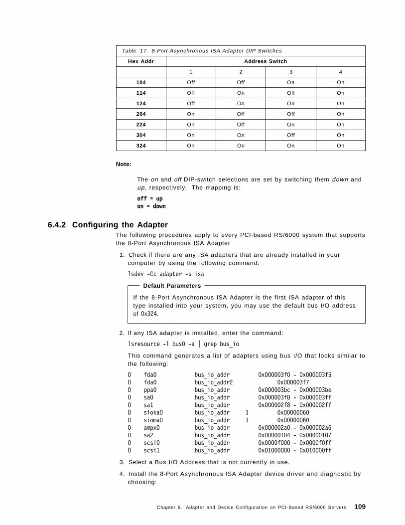
Note:
The on and off DIP-switch selections are set by switching them down andup, respectively. The mapping is:
off = upon = down
Table 17. 8-Port Asynchronous ISA Adapter DIP Switches
Hex Addr Address Switch
1 2 3 4
104 Off Off On On
114 Off On Off On
124 Off On On On
204 On Off Off On
224 On Off On On
304 On On Off On
324 On On On On
6.4.2 Configuring the AdapterThe following procedures apply to every PCI-based RS/6000 system that supportsthe 8-Port Asynchronous ISA Adapter
1. Check if there are any ISA adapters that are already installed in yourcomputer by using the following command:
lsdev -Cc adapter -s isa
Default Parameters
If the 8-Port Asynchronous ISA Adapter is the first ISA adapter of thistype installed into your system, you may use the default bus I/O addressof 0x324.
2. If any ISA adapter is installed, enter the command:
lsresource -l bus0 -a | grep bus_io
This command generates a list of adapters using bus I/O that looks similar tothe following:
O fda0 bus_io_addr 0x000003f0 - 0x000003f5O fda0 bus_io_addr2 0x000003f7O ppa0 bus_io_addr 0x000003bc - 0x000003beO sa0 bus_io_addr 0x000003f8 - 0x000003ffO sa1 bus_io_addr 0x000002f8 - 0x000002ffO sioka0 bus_io_addr 1 0x00000060O sioma0 bus_io_addr 1 0x00000060O ampx0 bus_io_addr 0x000002a0 - 0x000002a6O sa2 bus_io_addr 0x00000104 - 0x00000107O scsi0 bus_io_addr 0x0000f000 - 0x0000f0ffO scsi1 bus_io_addr 0x01000000 - 0x010000ff
3. Select a Bus I/O Address that is not currently in use.
4. Install the 8-Port Asynchronous ISA Adapter device driver and diagnostic bychoosing:
Chapter 6. Adapter and Device Configuration on PCI-Based RS/6000 Servers 109

smit isa
• Install ISA Adapter Software
to install the fileset device.isa.cxia.
5. After installing the software, you might enter:
smit isa
• Add an ISA Adapter
6. Select pcxr isa IBM 8-Port Async, EIA-232 (ISA) from the SMIT pop-up menu.
7. Select bus1 Available ISA Bus from the following SMIT pop-up menu.
8. From the menu described in Figure 36, select the correct Bus I/O Address,and press Enter .
� �Add a IBM 8-Port Async, EIA-232 (ISA) Adapter
Type or select values in entry fields.Press Enter AFTER making all desired changes.
[Entry Fields]Device Type pcxrDevice Class adapterDevice Subclass isaParent Device bus1Bus I/O Address 0x324
F1=Help F2=Refresh F3=Cancel F4=ListF5=Reset F6=Command F7=Edit F8=ImageF9=Shell F10=Exit Enter=Do� �
Figure 36. SMIT Configuration Menu for Adding an 8-Port Asynchronous ISA Adapter
This configuration menu does not provide the capability to only define theadapter without attempting to configure it. So, the configuration operationwill fail because the adapter is not yet physically installed on the system. Ifno Bus I/O Address conflict are detected, the following message will bedisplayed:
sa2 DefinedMethod error (/usr/lib/methods/cfgcxma):
0514-040 Error initializing a device into the kernel.
sa2 deleted
It does not matter. You should use this procedure just to make sure that theselected adapter parameter is correct.
110 Introduction to PCI-Based RS/6000 Servers

9. If the Bus I/O Address is in conflict with the parameter setting for anotherISA adapter already installed, the following message will be displayed:
sa3 Definedlsresource : The attribute(s) for some device(s) in the systemcould not be resolved. To resolve conflicts, attribute(s) need to bemodified. A suggested value for each attribute is provided.
DEVICE ATTRIBUTE CURRENT SUGGESTED DESCRIPTION
--------------- --------------- --------- --------- -----------sa3 bus_io_addr 0x324 0x304 Connection address
Method error (/usr/lib/methods/cfgcxma):0514-040 Error initializing a device into the kernel.
sa3 deleted
Change the parameter value as suggested by the lsresource command, andpress Enter .
10. Once no parameters conflicts are reported, you can set the DIP switches onthe adapter card as described in Table 17 on page 109 to reflect theselected Bus I/O Address′s correct value.
11. Shut down and power-off the system.
12. Install physically the adapter on an ISA slot.
13. Power-on and reboot the system.
14. Configure the adapter using the fastpath smit isa, and repeat the procedurefrom step 5 to step 8.
15. Verify the results with the following command:
lsdev -Cc adapter -s isa
If the configuration was successful, the adapter will be available, and thesystem will display information similar to the following:
sa3 Available 01-01 IBM 8-Port Async, EIA-232 (ISA)
16. Once the adapter status is Available, you may proceed to configure theserial devices on its ports by using the smit devices fastpath.
6.5 128-Port EIA-232 Asynchronous ISA Adapter (FC 2933)This section provides information needed for installing and configuring the128-Port Asynchronous ISA Adapter. This adapter can be ordered as an optionalfeature on PCI-based RS/6000 servers.
The 128-Port Asynchronous ISA Adapter provides support for attaching amaximum of 128 EIA-232D asynchronous serial devices (such as terminals,modems and printers) to a system unit when used with one or more optionalRemote Asynchronous Nodes 16-Port EIA-232. It contains the followingcomponents:
• 128-port asynchronous card
• Two terminators
Chapter 6. Adapter and Device Configuration on PCI-Based RS/6000 Servers 111

• Asynchronous wrap plug
The device driver for the 128-Port Asynchronous ISA Adapter is included indevices.isa.cxia128 fileset.
Note
Refer to the 128-Port Asynchronous ISA Adapter Installation Guide shippedwith the adapter for detailed information on this adapter.
6.5.1 DIP-Switch SettingThe only parameter you have to set to install the adapter into the system is theBus I/O Address. Its possible values are set with four switches at the rear of theadapter, and the possible switch settings are described in the following table.
Note:
The on and off DIP-switch selections are set by switching them down andup, respectively. The mapping is:
off = upon = down
Table 18. 128-Port Asynchronous ISA Adapter DIP Switches
Hex Addr Address Switch
1 2 3 4
108 Off Off On On
118 Off On Off On
128 Off On On On
208 On Off Off On
228 On Off On On
308 On On Off On
328 On On On On
6.5.2 Configuring the AdapterThe following procedures apply to every PCI-based RS/6000 system that supportsthe 128-Port Asynchronous ISA Adapter.
1. Check if there are any ISA adapters that are already installed in yourcomputer by using the following command:
lsdev -Cc adapter -s isa
Default Parameters
If the 128-Port Asynchronous ISA Adapter is the first ISA adapter of thistype installed into your system, you may use the default Bus I/O Addressof 0x328
2. If any ISA adapter is installed, enter the command:
lsresource -l bus0 -a | grep bus_io
112 Introduction to PCI-Based RS/6000 Servers

This command generates a list of adapters using bus I/O that looks similar tothe following:
O fda0 bus_io_addr 0x000003f0 - 0x000003f5O fda0 bus_io_addr2 0x000003f7O ppa0 bus_io_addr 0x000003bc - 0x000003beO sa0 bus_io_addr 0x000003f8 - 0x000003ffO sa1 bus_io_addr 0x000002f8 - 0x000002ffO sioka0 bus_io_addr 1 0x00000060O sioma0 bus_io_addr 1 0x00000060O ampx0 bus_io_addr 0x000002a0 - 0x000002a6O sa2 bus_io_addr 0x00000104 - 0x00000107O scsi0 bus_io_addr 0x0000f000 - 0x0000f0ffO scsi1 bus_io_addr 0x01000000 - 0x010000ff
3. Select a Bus I/O Address that is not currently in use.
4. Install the 128-Port Asynchronous ISA Adapter device driver and diagnosticby choosing:
smit isa
• Install ISA Adapter Software
to install the fileset device.isa.cxia128.
5. After installing the software, you might enter:
smit isa
• Add an ISA Adapter
6. Select cxia isa IBM 128-Port Async, EIA-232 (ISA) from the SMIT pop-upmenu.
7. Select bus1 Available ISA Bus from the following SMIT pop-up menu.
8. From the menu described in Figure 37 on page 114, select the correct BusI/O Address, and press Enter .
Chapter 6. Adapter and Device Configuration on PCI-Based RS/6000 Servers 113

� �Add an IBM 128-Port Async, EIA-232 (ISA) Adapter
Type or select values in entry fields.Press Enter AFTER making all desired changes.
[Entry Fields]Device Type cxiaDevice Class adapterDevice Subclass isaParent Device bus1Bus I/O Address 0x328Line 1 Speed 1.2MLine 1 Cable Type 8
Node 1 Comm Mode directNode 2 Comm Mode directNode 3 Comm Mode directNode 4 Comm Mode direct
Line 2 Speed 1.2MLine 2 Cable Type 8
Node 1 Comm Mode directNode 2 Comm Mode directNode 3 Comm Mode directNode 4 Comm Mode direct
F1=Help F2=Refresh F3=Cancel F4=ListF5=Reset F6=Command F7=Edit F8=ImageF9=Shell F10=Exit Enter=Do� �
Figure 37. SMIT Configuration Menu for Adding an 128-Port Asynchronous ISA Adapter
This configuration menu does not provide the capability to only define theadapter without attempting to configure it. So, the configuration operationwill fail because the adapter is not yet physically installed on the system. Ifno Bus I/O Address conflict are detected, the following message will bedisplayed:
cxia0 DefinedMethod error (/usr/lib/methods/cfgcxma):
0514-040 Error initializing a device into the kernel.
cxia0 deleted
It does not matter. You should use this procedure just to make sure that theselected adapter parameter is correct.
9. If the Bus I/O Addresses are in conflict with another parameter set foranother ISA adapter already installed, the following message will bedisplayed:
cxia0 Definedlsresource : The attribute(s) for some device(s) in the systemcould not be resolved. To resolve conflicts, attribute(s) need to bemodified. A suggested value for each attribute is provided.
DEVICE ATTRIBUTE CURRENT SUGGESTED DESCRIPTION
--------------- --------------- --------- --------- -----------cxia0 bus_io_addr 0x328 0x308 Connection address
114 Introduction to PCI-Based RS/6000 Servers

Method error (/usr/lib/methods/cfgcxma):0514-040 Error initializing a device into the kernel.
cxia0 deleted
Change the parameter value as suggested by the lsresource command, andpress Enter .
10. Once no parameters conflicts are reported, you can set the DIP switches onthe adapter card, as described in Table 18 on page 112, to reflect theselected Bus I/O Address correct value.
11. Shut down and power-off the system.
12. Physically install the adapter on an ISA slot.
13. Power on and reboot the system.
14. Configure the adapter using the fastpath smit isa, and repeat the procedurefrom step 5 to step 8.
15. Verify the results with the following command:
lsdev -Cc adapter -s isa
If the configuration was successful, the adapter will be available, and thesystem will display information similar to the following:
cxia0 Available 01-02 IBM 128-Port Async, EIA-232 (ISA)
16. Once the adapter status is Available, you may proceed to configure theserial devices on its ports using the smit devices fastpath.
6.6 4-Port Multi-Protocol ISA Adapter (FC 2701)This section provides information needed for installing and configuring the 4-PortMulti-Protocol ISA Adapter. This adapter can be ordered as an optional featureon PCI-based RS/6000 servers.
The 4-Port Multi-Protocol ISA Adapter provides asynchronous support andsynchronous communication. The adapter consists of a base card and adaughter card. The two cards are physically connected and require a single ISAbus card slot.
The device driver for 4-Port Multi-Protocol ISA Adapter is included indevices.isa.mm2 fileset.
Note
Refer to the 4-Port Multi-Protocol ISA Adapter Installation Guide shippedwith the adapter for detailed information on this adapter.
Chapter 6. Adapter and Device Configuration on PCI-Based RS/6000 Servers 115

6.6.1 Cable Selections for 4-Port Multiprotocol InterfaceThis adapter can support four different physical interfaces by using an IBM 4-PortMultiprotocol Interface Cable (feature #2705).
This cable is 3.1 meters (10 feet) long. It has a 78-pin connector on one end anda molded distribution block on the other end that contains six 25-pin connectorsand three 15-pin connector for the different physical interfaces supported.
The following table shows the supported interfaces for each port.
The maximum cable lengths that are supported for the various communicationsprotocols are described in the following table.
Table 19. Physical Interfaces on 4-Port Mult iprotocol Interface Cable
Port Number Supported Interfaces
# 0 EIA-232 EIA-422 V.35 X.21
# 1 EIA-232 - V.35 -
# 2 EIA-232 EIA-422 - -
# 3 EIA-232 - - -
Table 20. Maximum Cable Length
Protocol Length (meters) Length (feet)
RS-232 15.2 50
V.35 15.2 50
RS-422 122 400
X.21 122 400
6.6.2 DIP-Switch SettingThe 4-Port Multi-Protocol ISA Adapter has a 10-position DIP switch which is usedto set the following parameters:
You do not need to set every DIP switch on the adapter to configure it. The onlyDIP switches you have to change are those referring to Interrupt Level and BusI/O Address.
The DIP switches indicating the Memory Size, the Edge Connector and theBus-Width can be left in the default position set by the factory.
Table 21. DIP-Switches on 4-Port Multi-Protocol ISA Adapter
Parameter Switch Number(s)
Interrupt Level 1-2-3
Memory Size 4
Bus I/O Address 5-6-7-8
Edge Connector 9
Bus Width 10
116 Introduction to PCI-Based RS/6000 Servers

The following table shows the parameters values you may want to select inorder to define the Interrupt Level and the Bus I/O Address for a conflict-freeconfiguration of your first, second and third 4-Port Multiprotocol adapters.
Notes:
Refer to the document Adapters, Devices, and Cable Information for MultiBus Systems, SA38-0516-00, for detailed information on DIP-switchpositions for setting other parameter values.
The on and off DIP-switch selections are set by switching them down andup, respectively. The mapping is:
off = upon = down
�a� This switch is factory set to indicate the size of RAM installed on theadapter. Verify that the position of this switch is off to reflect a RAM sizeof 1 MB.
�b� Indicates whether a one-edge (62-pin) or a two-edge (62-pin and36-pin) connector is used to hold your adapter.on = two-edged / off = one-edged
�c� Sets the bus width and should generally be set to 8-bit.on = 8-bit / off = 16-bit
Table 22. 4-Port Mult iprotocol Adapter: DIP-Switch Suggested Settings
DipSwitch
#
Position Comment
FirstAdapter
SecondAdapter
ThirdAdapter
1 on off on IRQ Level
• First Card: 7• Second Card: 9• Third Card: 10
2 off off on
3 on on off
4 off off off Memory Size �a�
5 off off off I/O Port Address
• First Card: 06A0• Second Card: 0EA0• Third Card: 016A0
6 on off on
7 on on off
8 on on on
9 on on on Edge Connector �b�
10 off off off Bus-Width �c�
6.6.3 Configuring the AdapterThe following procedures apply to every PCI-based RS/6000 system that supportthe 4-Port Multi-Protocol ISA Adapter.
The configuration for this adapter requires you to specify the Interrupt Level, theBus I/O Address and the Bus Memory Address to be used with the adapter.
Chapter 6. Adapter and Device Configuration on PCI-Based RS/6000 Servers 117
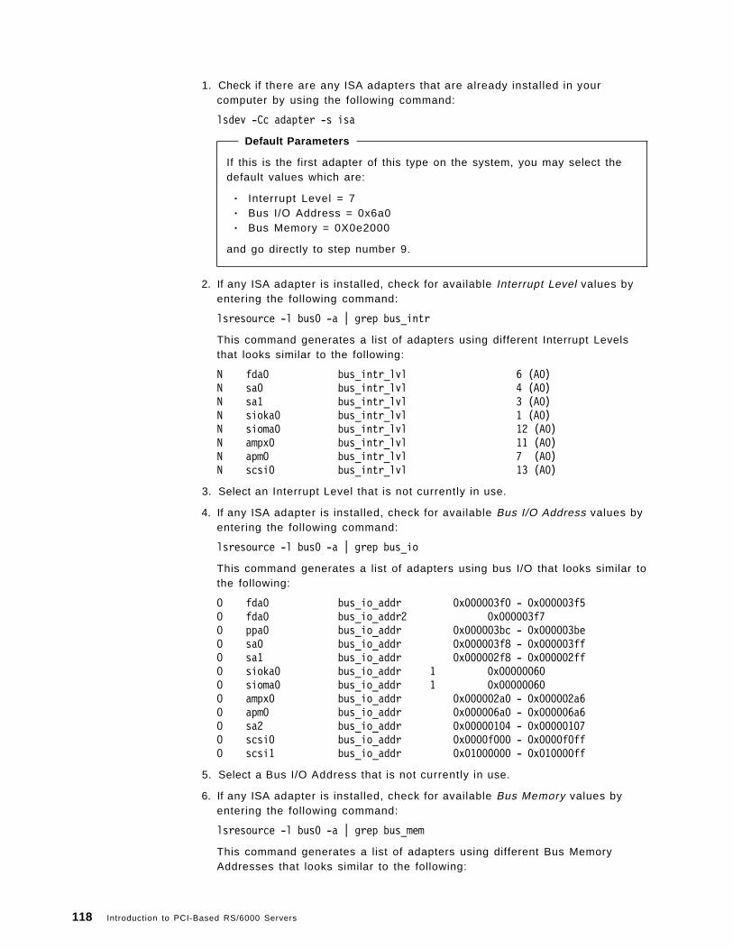
1. Check if there are any ISA adapters that are already installed in yourcomputer by using the following command:
lsdev -Cc adapter -s isa
Default Parameters
If this is the first adapter of this type on the system, you may select thedefault values which are:
• Interrupt Level = 7• Bus I/O Address = 0x6a0• Bus Memory = 0X0e2000
and go directly to step number 9.
2. If any ISA adapter is installed, check for available Interrupt Level values byentering the following command:
lsresource -l bus0 -a | grep bus_intr
This command generates a list of adapters using different Interrupt Levelsthat looks similar to the following:
N fda0 bus_intr_lvl 6 (A0)N sa0 bus_intr_lvl 4 (A0)N sa1 bus_intr_lvl 3 (A0)N sioka0 bus_intr_lvl 1 (A0)N sioma0 bus_intr_lvl 12 (A0)N ampx0 bus_intr_lvl 11 (A0)N apm0 bus_intr_lvl 7 (A0)N scsi0 bus_intr_lvl 13 (A0)
3. Select an Interrupt Level that is not currently in use.
4. If any ISA adapter is installed, check for available Bus I/O Address values byentering the following command:
lsresource -l bus0 -a | grep bus_io
This command generates a list of adapters using bus I/O that looks similar tothe following:
O fda0 bus_io_addr 0x000003f0 - 0x000003f5O fda0 bus_io_addr2 0x000003f7O ppa0 bus_io_addr 0x000003bc - 0x000003beO sa0 bus_io_addr 0x000003f8 - 0x000003ffO sa1 bus_io_addr 0x000002f8 - 0x000002ffO sioka0 bus_io_addr 1 0x00000060O sioma0 bus_io_addr 1 0x00000060O ampx0 bus_io_addr 0x000002a0 - 0x000002a6O apm0 bus_io_addr 0x000006a0 - 0x000006a6O sa2 bus_io_addr 0x00000104 - 0x00000107O scsi0 bus_io_addr 0x0000f000 - 0x0000f0ffO scsi1 bus_io_addr 0x01000000 - 0x010000ff
5. Select a Bus I/O Address that is not currently in use.
6. If any ISA adapter is installed, check for available Bus Memory values byentering the following command:
lsresource -l bus0 -a | grep bus_mem
This command generates a list of adapters using different Bus MemoryAddresses that looks similar to the following:
118 Introduction to PCI-Based RS/6000 Servers

B ampx0 bus_mem_addr 0x000e0000 - 0x000e1fffB apm0 bus_mem_addr 0x000e2000 - 0x000e3fffB gga0 bus_mem_start 0x01000000 - 0x01ffffff
7. Select a bus memory address that is not currently in use.
The valid bus memory values for use with the 4-Port Multi-Protocol ISAAdapter start at 0x0e0000 and increment by 0x002000. For example0x0e2000, 0x0e4000, 0x0e6000, etc. The previous example shows ampx0 isusing the first bus memory range of 0X0e000 and apm0 is using the secondrange of 0x0e2000.
8. Install the 4-Port Multi-Protocol ISA Adapter device driver and diagnostic bychoosing:
smit isa
• Install ISA Adapter Software
to install the fileset device.isa.mm2.
9. After installing the software, you might enter:
smit isa
• Add an ISA Adapter
10. Select portmaster isa Multiport Model 2 Adapter from the SMIT pop-up menu.
11. Select bus1 Available ISA Bus from the following SMIT pop-up menu.
12. From the menu described in Figure 38 select the correct Interrupt Level, BusI/O Address and Bus Memory values, and press Enter .
� �Add a Multiport Model 2 Adapter
Type or select values in entry fields.Press Enter AFTER making all desired changes.
[Fields]Description Multiport Model 2 AdapterParent Device bus1ISA Interrupt Level [7]Bus IO Address [0x6A0]Bus Memory Address [0xE2000]Define device only, do not configure yes
F1=Help F2=Refresh F3=Cancel F4=ListF5=Reset F6=Command F7=Edit F8=ImageF9=Shell F10=Exit Enter=Do
� �Figure 38. SMIT Configuration Menu for Adding an 4-Port Multi-Protocol ISA Adapter
This configuration menu also provides the capability to select the Definedevice only, do not configure option to have the adapter defined but notconfigured. Change this field value to yes . It will allow you to define the
Chapter 6. Adapter and Device Configuration on PCI-Based RS/6000 Servers 119

adapter without configuring it. If any parameter conflicts were detected, anerror message similar to the following is displayed:
apm1 Definedlsresource : The attribute(s) for some device(s) in the systemcould not be resolved. To resolve conflicts, attribute(s) need to bemodified. A suggested value for each attribute is provided.
DEVICE ATTRIBUTE CURRENT SUGGESTED DESCRIPTION
--------------- --------------- --------- --------- -----------apm1 bus_intr_lvl 7 9 Interrupt Levelapm1 bus_io_addr 0x6a0 0xea0 Connection Address
apm1 deleted
Change the parameter value as suggested by the lsresource command, andpress Enter .
13. Once no parameters conflicts are reported, you can set the DIP switches onthe adapter card as described in 6.6.2, “DIP-Switch Setting” on page 116, toreflect the selected parameters′ correct values.
14. Shut down and power-off the system.
15. Physically install the adapter on an ISA slot.
16. Power on and reboot the system.
17. Configure the adapter using the fastpath:
smit isa
• Configure a Defined ISA Adapter
18. Verify the results with the following command:
lsdev -Cc adapter -s isa
If the configuration was successful, the adapter will be available, and thesystem will display information similar to the following:
apm1 Available 01-03 IBM Multiport Model 2 Adapter
19. Once the adapter status is Available, you may proceed to configure its portsby using the smit devices fastpath.
6.7 X.25 Interface Co-Processor ISA Adapter (FC 2961)This section provides information needed for installing and configuring the X.25Interface Co-Processor ISA Adapter. This adapter can be ordered as an optionalfeature on PCI-based RS/6000 servers.
The X.25 Interface Co-Processor ISA Adapter, with supporting software, enablesthe attachment of an ISA-bus-compatible system to an X.25 packet-switchednetwork so that the computer can operate as a packet terminal.
In AIX Version 4, support for X.25 communication is provided with the IBMAIXLink/X.25 Version 1.1 LPP (feature code 5696-926).
120 Introduction to PCI-Based RS/6000 Servers

The device driver for X.25 Interface Co-Processor ISA Adapter is included indevices.isa.c1x fileset that can be found in the AIX Version 4 base operationsystem shipping.
Note
Refer to the X.25 Interface Co-Processor ISA Adapter Installation Guideshipped with the adapter for detailed information on this adapter.
6.7.1 DIP-Switch SettingThe X.25 Interface Co-Processor ISA Adapter has a 10-position DIP switch whichis used to set the following parameters:
You do not need to set every DIP switch on the adapter to configure it. The onlyDIP switches you have to change are those referring to Interrupt Level and BusI/O Address.
The DIP switches indicating the Memory Size, Edge Connector and Bus-Widthcan be left in the default position set by the factory.
The following table shows the parameter values you may want to select in orderto define the Interrupt Level and the Bus I/O Address for a conflict-freeconfiguration of your first, second and third X.25 Co-Processor Adapters.
Table 23. DIP Switches on the X.25 Interface Co-Processor ISA Adapter
Parameter Switch Number(s)
Interrupt Level 1-2-3
Memory Size 4
Bus I/O Address 5-6-7-8
Edge Connector 9
Bus Width 10
Table 24 (Page 1 of 2). X.25 Adapter: DIP-Switch Suggested Settings
DipSwitch
#
Position
CommentFirstAdapter
SecondAdapter
ThirdAdapter
1 off off on IRQ Level
• First Card: 11• Second Card: 9• Third Card: 7
2 on off off
3 off on on
4 on on on Memory Size �a�
5 on off onI/O Port Address
• First Card: 02A0• Second Card: 06A0• Third Card: 0AA0
6 on on off
7 on on on
8 on on on
9 on on on Edge Connector �b�
Chapter 6. Adapter and Device Configuration on PCI-Based RS/6000 Servers 121

Notes:
Refer to the document Adapters, Devices, and Cable Information for MultiBus Systems, SA38-0516-00, for detailed information on DIP-switchpositions for setting other parameter values.
The on and off DIP-switch selections are set by switching them down andup, respectively. The mapping is:
off = upon = down
�a� This switch is factory set to indicate the size of RAM installed on theadapter. Verify that the position of this switch is on to reflect a RAM sizeof 512 KB.
�b� Indicates whether a one-edge (62-pin) or a two-edge (62-pin and36-pin) connector is used to hold your adapter.on = two-edged / off = one-edged
�c� Sets the bus width and should generally be set to 8-bit.on = 8-bit / off = 16-bit
Table 24 (Page 2 of 2). X.25 Adapter: DIP-Switch Suggested Settings
DipSwitch
#
Position
CommentFirstAdapter
SecondAdapter
ThirdAdapter
10 on on on Bus-Width �c�
6.7.2 Configuring the AdapterThe following procedures apply to every PCI-based RS/6000 system that supportsthe X.25 Interface Co-Processor ISA Adapter.
The configuration for this adapter requires you to specify the Interrupt Level, theBus I/O Address and the Bus Memory Address to be used with the adapter.
1. Check if there are any ISA adapters that are already installed in yourcomputer by using the following command:
lsdev -Cc adapter -s isa
Default Parameters
If this is the first adapter of this type on the system, you may select thedefault values:
• Interrupt Level = 11• Bus I/O Address = 0x2a0• Bus Memory = 0X0e0000
and go directly to step number 9.
2. If any ISA adapter is installed, check for available Interrupt Level values byentering the following command:
lsresource -l bus0 -a | grep bus_intr
122 Introduction to PCI-Based RS/6000 Servers

This command generates a list of adapters using different Interrupt Levelsthat looks similar to the following:
N fda0 bus_intr_lvl 6 (A0)N sa0 bus_intr_lvl 4 (A0)N sa1 bus_intr_lvl 3 (A0)N sioka0 bus_intr_lvl 1 (A0)N sioma0 bus_intr_lvl 12 (A0)N ampx0 bus_intr_lvl 11 (A0)N scsi0 bus_intr_lvl 13 (A0)
3. Select an Interrupt Level that is not currently in use.
4. If any ISA adapter is installed, check for available Bus I/O Address values byentering the following command:
lsresource -l bus0 -a | grep bus_io
This command generates a list of adapters using bus I/O that looks similar tothe following:
O fda0 bus_io_addr 0x000003f0 - 0x000003f5O fda0 bus_io_addr2 0x000003f7O ppa0 bus_io_addr 0x000003bc - 0x000003beO sa0 bus_io_addr 0x000003f8 - 0x000003ffO sa1 bus_io_addr 0x000002f8 - 0x000002ffO sioka0 bus_io_addr 0x00000060O sioma0 bus_io_addr 0x00000060O ampx0 bus_io_addr 0x000002a0 - 0x000002a6O sa2 bus_io_addr 0x00000104 - 0x00000107O scsi0 bus_io_addr 0x0000f000 - 0x0000f0ffO scsi1 bus_io_addr 0x01000000 - 0x010000ff
5. Select a Bus I/O Address that is not currently in use.
6. If any ISA adapter is installed, check for available Bus Memory values byentering the following command:
lsresource -l bus0 -a | grep bus_mem
This command generates a list of adapters using different Bus MemoryAddresses that looks similar to the following:
B ampx0 bus_mem_addr 0x000e0000 - 0x000e1fffB apm0 bus_mem_addr 0x000e2000 - 0x000e3fffB gga0 bus_mem_start 0x01000000 - 0x01ffffff
7. Select a Bus Memory that is not currently in use.
The valid Bus Memory values for use with the X.25 Interface Co-ProcessorISA Adapter start at 0x0e0000 and increment by 0x002000. For example, theyare 0x0e2000, 0x0e4000, 0x0e6000, and so on. The previous example showsampx0 is using the first Bus Memory range of 0X0e000, and apm0 is using thesecond range of 0x0e2000.
8. Install the X.25 Interface Co-Processor ISA Adapter device driver anddiagnostic by choosing:
smit isa
• Install ISA Adapter Software
to install the fileset device.isa.c1x.
9. After installing the software, you might enter:
smit isa
Chapter 6. Adapter and Device Configuration on PCI-Based RS/6000 Servers 123

• Add an ISA Adapter
10. Select articmpx isa X.25 Coprocessor/1 Adapter from the SMIT pop-up menu.
11. Select bus1 Available ISA Bus from the following SMIT pop-up menu.
12. From the menu described in Figure 39, select the correct Interrupt Level,Bus I/O Address and Bus Memory values, and press Enter .
� �Add a X.25 Coprocessor/1 Adapter
Type or select values in entry fields.Press Enter AFTER making all desired changes.
[Fields]Description X.25 Coprocessor/1 AdapterParent Device bus1ISA Interrupt Level [11]Bus IO Address [0x2A0]Bus Memory Address [0xE0000]Define device only, do not configure yes
F1=Help F2=Refresh F3=Cancel F4=ListF5=Reset F6=Command F7=Edit F8=ImageF9=Shell F10=Exit Enter=Do
� �Figure 39. SMIT Configuration Menu for Adding an X.25 Interface Co-Processor ISAAdapter
This configuration menu also provides the capability to select the Definedevice only, do not configure option to have the adapter defined but notconfigured. Change this field value to yes . It will allow you to define theadapter without configuring it. If any parameter conflicts were detected, anerror message similar to the following is displayed:
ampx1 Definedlsresource : The attribute(s) for some device(s) in the systemcould not be resolved. To resolve conflicts, attribute(s) need to bemodified. A suggested value for each attribute is provided.
DEVICE ATTRIBUTE CURRENT SUGGESTED DESCRIPTION
--------------- --------------- --------- --------- -----------ampx1 bus_intr_lvl 11 9 Interrupt Levelampx1 bus_io_addr 0x2a0 0xaa0 Connection Address
ampx1 Deleted
Change the parameter value as suggested by the lsresource command, andpress Enter .
124 Introduction to PCI-Based RS/6000 Servers

13. Once no parameters conflicts are reported, you can set the DIP switches onthe adapter card, as described in 6.7.1, “DIP-Switch Setting” on page 121, toreflect the selected parameters′ correct values.
14. Shut down and power-off the system.
15. Physically install the adapter on an ISA slot.
16. Power on and reboot the system.
17. Configure the adapter using the fastpath:
smit isa
• Configure a Defined ISA Adapter
18. Verify the results with the following command:
lsdev -Cc adapter -s isa
If the configuration was successful, the adapter will be available, and thesystem will display information similar to the following:
ampx1 Available 01-04 X.25 Coprocessor/1 Adapter
19. Once the adapter status is Available, you may proceed to configuring andsetting up a X.25 network. Refer to the AIX/6000 X.25 LPP Cookbook,GG24-4475, redbook which explains the X.25 concepts and providesprocedures to set up an X.25 network using the AIXLink/X.25 LPP software.
6.8 Ethernet and Token-Ring ISA AdaptersIn this section, we describe how to configure ISA LAN Adapters. These adapterscannot be ordered as optional features on the PCI servers because they are notofficially supported on this platform, but they are the same adapters that can beordered as optional features on 40P and 43P systems.
The ISA LAN Adapters that we tested are the ISA Ethernet Adapter and the Auto16/4 Token-Ring ISA Adapter.
Both adapters have no DIP switches for setting the operating system parametersto be used with them. They have to be set at firmware level. As these adaptersare not officially supported by the PCI-based RS/6000 servers, it is not possibleto set the adapters′ parameters using the Model E20 or Model F30 firmware.The only way to set them is to install the adapters on a PCI-based RISC/6000workstation (40P/43P), or on a PC, by using the software provided with theadapter.
The general procedure to install and configure these ISA adapters is the sameprocedure to that described in 6.3, “ISA Adapter Configuration” on page 104,except for step number 5, as described in the following list:
1. Record parameter settings of ISA adapters already configured.
2. Select parameter values for new ISA adapters.
3. Install the adapter device driver.
4. Use smit isa to define the adapter.
5. Set the proper adapter parameters at f irmware level by using a PCI-basedRISC/6000 workstation or by using a PC and the software provided by theadapter.
Chapter 6. Adapter and Device Configuration on PCI-Based RS/6000 Servers 125

6. Physically install the adapter on the PCI-based RISC/6000 server in a ISAslot.
7. Configure the adapter by using smit isa.
Since you could define adapters parameters at firmware level more than onetime, if some others adapters are installed on the PCI-based server system, werecommend you configure the adapter at the AIX level on the PCI-based serversystem in the defined state before setting the right parameters, as in stepnumber 5.
6.8.1 Configuring an ISA Ethernet AdapterBefore the hardware parameters for the new ISA adapter can be selected andtested using the 40P or 43P firmware, you will have to tell AIX the values ofthese parameters.
The configuration for ISA Ethernet adapter requires you to specify the InterruptLevel, the Bus I/O Address, the Bus Memory and the Connection or Media Type.These parameters can assume the following values:
• Interrupt Level = 5, 7, 9 or 11
• Bus I/O Address = 0x240, 0x280, 0x300, and so on
• Memory Address = 0xc000, 0xc4000, 0xc8000, and so on
• Connection Type = bnc, dix, tp, and so on
1. Check if there are any ISA adapters that are already installed in yourcomputer by using the following command:
lsdev -Cc adapter -s isa
Defaults Parameters
If this is the first ISA adapter on the system, you may select the defaultvalues:
• Interrupt Level = 11• Bus I/O Address = 0x300• Bus Memory = 0X0c0000• Connection Type = bnc
and go directly to step number 9.
2. If any ISA adapter is installed, check for available Interrupt Level values byentering the following command:
lsresource -l bus0 -a | grep bus_intr
This command generates a list of adapters using different Interrupt Levelsthat looks similar to the following:
N fda0 bus_intr_lvl 6 (A0)N sa0 bus_intr_lvl 4 (A0)N sa1 bus_intr_lvl 3 (A0)N sioka0 bus_intr_lvl 1 (A0)N sioma0 bus_intr_lvl 12 (A0)N ampx0 bus_intr_lvl 11 (A0)N scsi0 bus_intr_lvl 13 (A0)N ent0 bus_intr_lvl 9 (A0)
3. Select an Interrupt Level that is not currently in use.
126 Introduction to PCI-Based RS/6000 Servers

4. If any ISA adapter is installed, check for available Bus I/O Address values byentering the following command:
lsresource -l bus0 -a | grep bus_io
This command generates a list of adapters using bus I/O that looks similar tothe following:
O fda0 bus_io_addr 0x000003f0 - 0x000003f5O fda0 bus_io_addr2 0x000003f7O ppa0 bus_io_addr 0x000003bc - 0x000003beO sa0 bus_io_addr 0x000003f8 - 0x000003ffO sa1 bus_io_addr 0x000002f8 - 0x000002ffO sioka0 bus_io_addr 1 0x00000060O sioma0 bus_io_addr 1 0x00000060O ampx0 bus_io_addr 0x000002a0 - 0x000002a6O sa2 bus_io_addr 0x00000104 - 0x000001070 ent0 bus_io_addr 0x00000300 - 0x0000031fO scsi0 bus_io_addr 0x0000f000 - 0x0000f0ffO scsi1 bus_io_addr 0x01000000 - 0x010000ff
5. Select a Bus I/O Address that is not currently in use.
6. If any ISA adapter is installed, check for available Bus Memory values byentering the following command:
lsresource -l bus0 -a | grep bus_mem
This command generates a list of adapters using different Bus MemoryAddresses that looks similar to the following:
B ampx0 bus_mem_addr 0x000e0000 - 0x000e1fffB apm0 bus_mem_addr 0x000e2000 - 0x000e3fffB ent0 bus_mem_addr 0x000c0000 - 0x000c3fffB gga0 bus_mem_start 0x01000000 - 0x01ffffff
7. Select a Bus Memory that is not currently in use.
The valid Bus Memory values for use with the ISA Ethernet Adapter start at0xc0000 and increment by 0x04000. For example, they are 0xc4000, 0xc8000,and so on. The previous example shows ent0 is using the first Bus Memoryrange of 0Xc0000.
8. Install the ISA Ethernet Adapter device driver and diagnostic by choosing:
smit isa
• Install ISA Adapter Software
to install the fileset device.isa.ethernet
9. After installing the software, you might enter:
smit isa
• Add an ISA Adapter
10. Select ethernet isa IBM Ethernet ISA Adapter from the SMIT pop-up menu.
11. Select bus1 Available ISA Bus from the following SMIT pop-up menu.
12. From the menu described in Figure 40 on page 128, select the correctInterrupt Level, Bus I/O Address, Bus Memory and Media Type values, andpress Enter .
Chapter 6. Adapter and Device Configuration on PCI-Based RS/6000 Servers 127

� �Add a Ethernet ISA Adapter
Type or select values in entry fields.Press Enter AFTER making all desired changes.
[Entry Fields]Description IBM ISA Ethernet AdapterParent Device bus1TRANSMIT queue size [64]Media Type [bnc]Bus I/O Address [0x300]Bus Interrupt Level [11]Bus Memory Address [0xc0000]Enable ALTERNATE ETHERNET address noALTERNATE ETHERNET address [0x]Define device only, do not configure yes
F1=Help F2=Refresh F3=Cancel F4=ListF5=Reset F6=Command F7=Edit F8=ImageF9=Shell F10=Exit Enter=Do
� �Figure 40. SMIT Configuration Menu for Adding an ISA Ethernet Adapter
This configuration menu also provides the capability to select the Definedevice only, do not configure option to have the adapter defined but notconfigured. Change this field value to yes . It will allow you to define theadapter without configuring it. If any parameter conflicts were detected, anerror message similar to the following is displayed:
ent1 Definedlsresource : The attribute(s) for some device(s) in the systemcould not be resolved. To resolve conflicts, attribute(s) need to bemodified. A suggested value for each attribute is provided.
DEVICE ATTRIBUTE CURRENT SUGGESTED DESCRIPTION
--------------- --------------- --------- --------- -----------ent1 bus_intr_lvl 11 5 Bus Interrupt Levelent1 bus_mem_addr 0xc0000 0xc4000 Bus Memory Addressent1 bus_io_addr 0x300 0x320 Bus I/O Address
ent1 Deleted
Change the parameter value as suggested by the lsresource command, andpress Enter .
Note: Instead of using the SMIT menu, you may use the following commandto select the previously set and tested parameters:
mkdev -c adapter -s isa -t ethernet -a bus_intr_lvl=IRQ \-a bus_io_addr=IO -a bus_mem_addr=MEM \-a media_type=TYPE -p bus1
where:
• IRQ is the interrupt level• IO is the I/O address
128 Introduction to PCI-Based RS/6000 Servers

• MEM is the shared memory address• TYPE is the type of cable connection you will be using
13. Once no parameters conflicts are reported, you can set the parameters onthe adapter card as described in 6.8.2, “Setting ISA Ethernet AdapterParameters at Firmware Level,” to reflect the selected parameters′ correctvalues.
14. Shut down and power-off the system.
15. Physically install the adapter on an ISA slot.
16. Power-on and reboot the system.
17. Configure the adapter using the fastpath:
smit isa
• Configure a Defined ISA Adapter
18. Verify the results with the following command:
lsdev -Cc adapter -s isa
If the configuration was successful, the adapter will be available, and thesystem will display information similar to the following:
ent1 Available 01-05 IBM ISA Ethernet Adapter
19. Once the adapter status is Available, you may proceed to configure thenetwork interfaces by using the smit inet fastpath.
6.8.2 Setting ISA Ethernet Adapter Parameters at Firmware LevelAs already stated in 6.8, “Ethernet and Token-Ring ISA Adapters” on page 125,the ISA Ethernet Adapter is not officially supported on the PCI-based RS/6000servers therefore its hardware parameters cannot be changed with the firmwareinstalled in those machines. The only way to set the parameters is to install theadapter on a 40P (firmware level 1.28 or newer), on a 43P (firmware level 1.06 ornewer), or on a PC, by using the software provided with the adapter.
The following procedures apply to the 40P and the 43P. They explain how to setthe ISA Ethernet Adapter hardware parameter values before physically installingit in the PCI-based RS/6000 server.
1. If there are any ISA adapters that are already installed in your computer,record their settings for later reference.
2. If your computer is up and running, shut the operating system down, andturn the power off.
3. Remove all existing ISA adapters from the machine.
4. Install the first new ISA Ethernet adapter, and insert the System ManagementServices diskette in the diskette drive.
5. Power-on your computer.
6. Access the services by pressing the F4 key as soon as the first screenappears. For additional information on the System Management Services,refer to the System User′s Guide that is shipped with your system.
7. Use the Up Arrow and Down Arrow keys to select Utilities , and press Enter .
8. Select Remote Initial Program Load Setup , and press Enter .
9. Select Adapter Parameters , and press Enter .
Chapter 6. Adapter and Device Configuration on PCI-Based RS/6000 Servers 129

10. Select IBM LAN Adapter for Ethernet , and press Enter .
Note
The Ethernet adapter entry will be displayed only if the Interrupt Level seton the adapter does not conflict with the any Interrupt Level used by thecomputer. For example, if your Ethernet adapter is set to interrupt 5 andyou install it on a 43P, the entry for the adapter will not be displayed, andyou will not be able to change the parameters. In this case, you willhave to use a PC or a 40P to change this parameter. Refer to the SystemUser′s Guide shipped with the computer for a list of the Interrupt-Level(IRQ) assignments on your system.
11. Select View or Set Parameters , and press Enter .
The system will display the parameters that can be viewed or changed.Those parameters are shown in Table 25.
The only parameters you can change are the I/O Port, the Connection Typeand the Interrupt Level parameters.
12. If you change any parameter, you will have to press the F2 key to save thenew values.
13. If you want to install additional new ISA Ethernet adapters, power-off thesystem, and repeat steps 3 through 11 for each new ISA Ethernet adapteryou want to install.
14. Install any adapters that were removed earlier in this procedure.
Table 25. Adapter Parameters
Attribute Description
Hardware AddressMAC Address (Medium Access Control) - Cannot bechanged.
I/O Port Assignment Select required I/O Port.
Shared MemoryAddress
Always shows 0e4000 and cannot be changed here.You can set it when defining the adapter to AIX.
Connection TypeSelect the type of connection you want to use(10Base2, 10Base5 and so forth).
Interrupt Assignment Select the Interrupt Request Level (IRQ).
6.8.3 Configuring the Auto 16/4 Token-Ring ISA AdapterBefore the hardware parameters for the new ISA adapter were selected andtested using the 40p or 43P firmware, you will have to tell AIX which are thevalues of these parameters.
The configuration for Auto 16/4 Token-Ring ISA Adapter requires you to specifythe Interrupt Level, the Bus I/O Address, the Shared Bus Memory Address, theLength of shared bus memory, the Address of bus memory used for BIOS, andthe Ring Speed. These parameters can assume the following values:
• Interrupt Level = 3, 9 or 11
• Bus I/O Address = 0xa20, 0xa24, 0xa28, and so on
• Shared Bus Memory Address = 0xc0000, 0xc4000, 0xc8000, and so on
• Length in shared bus memory = 8 KB, 16 KB, 32 KB, 64 KB
130 Introduction to PCI-Based RS/6000 Servers

• Address of bus memory for BIOS = 0xc8000, 0xca000, 0xcc000, and so on
• Ring Speed = 16 MB, 4 MB
1. Check if there are any ISA adapters that are already installed in yourcomputer, using the following command:
lsdev -Cc adapter -s isa
Defaults Parameters
If this is the first ISA adapter on the system, you may select the defaultvalues:
• Interrupt Level = 9• Bus I/O Address = 0xa20• Shared Bus Memory = 0X0d0000• Length in shared bus memory = 0x8000• Address of bus memory for BIOS = 0xcc000• Ring Speed = 16 MB
and go directly to step number 11.
2. If any ISA adapter is installed, check for available Interrupt Level values byentering the following command:
lsresource -l bus0 -a | grep intr_
This command generates a list of adapters using different Interrupt Levelsthat looks similar to the following:
N fda0 bus_intr_lvl 6 (A0)N sa0 bus_intr_lvl 4 (A0)N sa1 bus_intr_lvl 3 (A0)N sioka0 bus_intr_lvl 1 (A0)N sioma0 bus_intr_lvl 12 (A0)N tok0 intr_level 7 (A0)N ampx0 bus_intr_lvl 11 (A0)N scsi0 bus_intr_lvl 13 (A0)
3. Select an interrupt level that is not currently in use.
4. If any ISA adapter is installed, check for available Bus I/O Address values byentering the following command:
lsresource -l bus0 -a | grep bus_io
This command generates a list of adapters using bus I/O that looks similar tothe following:
O fda0 bus_io_addr 0x000003f0 - 0x000003f5O fda0 bus_io_addr2 0x000003f7O sa0 bus_io_addr 0x000003f8 - 0x000003ffO sa1 bus_io_addr 0x000002f8 - 0x000002ffO sioka0 bus_io_addr 1 0x00000060O sioma0 bus_io_addr 1 0x00000060O ppa0 bus_io_addr 0x000003bc - 0x000003beO tok0 bus_io_addr 0x00000a20 - 0x00000a23O ampx0 bus_io_addr 0x000002a0 - 0x000002a6O scsi0 bus_io_addr 0x01000000 - 0x010000ff
5. Select a Bus I/O Address that is not currently in use.
6. If any token-ring adapter is installed, check for available Shared Bus Memoryvalues by entering the following command:
Chapter 6. Adapter and Device Configuration on PCI-Based RS/6000 Servers 131

lsresource -l bus0 -a | grep shared_mem_addr
This command generates a list of ISA adapters using a Bus Memory Addressthat looks similar to the following:
B tok0 shared_mem_addr 0x000d0000 - 0x000d7fff
7. Select a Shared Memory Address that is not currently in use.
The valid Shared Memory values for use with the Auto 16/4 Token-Ring ISAAdapter start at 0xc0000 and increment depending on the length of SharedMemory that has been selected for the adapter.
8. If any ISA adapter is installed, check for available Address of shared memoryfor BIOS values by entering the following command:
lsresource -l bus0 -a | grep bios_addr
This command generates a list of ISA adapters using a Bus Memory Addressthat looks similar to the following:
B tok0 bios_addr 0x000dc000 - 0x000ddfff
9. Select an address of shared memory for BIOS that is not currently in use.
The valid ROM address for use with the Auto 16/4 Token-Ring ISA Adapterstart at 0xc8000 and increment by 0x00200.
10. Install the Auto 16/4 Token-Ring ISA Adapter device driver and diagnostic bychoosing:
smit isa
• Install ISA Adapter Software
to install the fileset device.isa.tokenring.
11. After installing the software, you might enter:
smit isa
• Add an ISA Adapter
12. Select tokenring isa IBM 16/4 PowerPC Token-Ring Adapter from the SMITpop-up menu.
13. Select bus1 Available ISA Bus from the following SMIT pop-up menu.
14. From the menu described in Figure 41 on page 133, select the correctInterrupt Level, Bus I/O Address, Bus Memory and Media Type values, andpress Enter .
132 Introduction to PCI-Based RS/6000 Servers

� �Add a Token Ring ISA Adapter
Type or select values in entry fields.Press Enter AFTER making all desired changes.
[Entry Fields]Description IBM 16/4 PowerPC Token-RingParent Device bus1Bus interrupt level [9]Address of bus memory used for BIOS [0xcc000]Bus I/O address [0xa20]Bus memory address [0xd0000]Width of shared bus memory [64k]RING speed [16]Receive ATTENTION MAC frame noReceive BEACON MAC frame noEnable ALTERNATE TOKEN RING address noALTERNATE TOKEN RING address [0x]Define device only, do not configure yes
F1=Help F2=Refresh F3=Cancel F4=ListF5=Reset F6=Command F7=Edit F8=ImageF9=Shell F10=Exit Enter=Do
� �Figure 41. SMIT Configuration Menu for Adding an Auto 16/4 Token-Ring ISA Adapter
This configuration menu also provides the capability to select the Definedevice only, do not configure option to have the adapter defined but notconfigured. Change this field value to yes . It will allow you to define theadapter without configuring it. If any parameter conflicts were detected, anerror message similar to the following is displayed:
tok1 Definedlsresource : The attribute(s) for some device(s) in the systemcould not be resolved. To resolve conflicts, attribute(s) need to bemodified. A suggested value for each attribute is provided.
DEVICE ATTRIBUTE CURRENT SUGGESTED DESCRIPTION
--------------- --------------- --------- --------- -----------tok1 bios_addr 0Xcc000 0xd800 ROM memory addresstok1 bus_io_addr 0xa20 0xa24 Bus I/O Addresstok1 shared_mem_addr 0xd0000 0xc0000 Bus Memory Address
tok1 Deleted
Change the parameter value as suggested by the lsresource command, andpress Enter .
Note: Instead of using the SMIT menu, you may use the following commandto select the previously set and tested parameters:
mkdev -c adapter -s isa -t tokenring -a intr_lvl=IRQ \-a bus_io_addr=IO -a shared_mem_addr=MEM \-a shared_mem_length=LEN -a bios_addr=BIOS-a ring_speed=SPEED -p bus1
where:
Chapter 6. Adapter and Device Configuration on PCI-Based RS/6000 Servers 133

• IRQ is the interrupt level• IO is the I/O address• MEM is the shared memory address• LEN is the length of shared memory• BIOS is the ROM memory address• SPEED is speed of the network ring
15. Once no parameters conflicts are reported, you can set the parameters onthe adapter card, as described in 6.8.4, “Setting Auto 16/4 Token-Ring ISAAdapter Parameters at Firmware Level,” to reflect the selected parameters′correct values.
16. Shut down and power-off the system.
17. Physically install the adapter on an ISA slot.
18. Power-on and reboot the system.
19. Configure the adapter by using the fastpath:
smit isa
• Configure a Defined ISA Adapter
20. Verify the results with the following command:
lsdev -Cc adapter -s isa
If the configuration was successful, the adapter will be available, and thesystem will display information similar to the following:
tok1 Available 01-06 IBM 16/4 PowerPC Token-Ring Adapter (isa)
21. Once the adapter status is Available, you may proceed to configure thenetwork interfaces by using the smit inet fastpath.
6.8.4 Setting Auto 16/4 Token-Ring ISA Adapter Parameters at Firmware LevelAs already stated in 6.8, “Ethernet and Token-Ring ISA Adapters” on page 125,the Auto 16/4 Token-Ring ISA Adapter is not officially supported on thePCI-based RS/6000 servers therefore its hardware parameters cannot bechanged with the firmware installed in those machines. The only way to set theparameters is to install the adapter on a 40P (firmware level 1.28 or newer), a43P (firmware level 1.06 or newer), or on a PC, by using the software providedwith the adapter.
The following procedures apply to the 40P and the 43P. They explain how to setthe Auto 16/4 Token-Ring ISA Adapter hardware parameter values beforephysically installing it in the PCI-based RS/6000 server.
The System Management Services utilities include the support needed toconfigure the adapter at firmware level. The configuration of the adapter issimilar to the configuration of the ISA Ethernet adapter explained in 6.8.2,“Setting ISA Ethernet Adapter Parameters at Firmware Level” on page 129.Follow steps 1 through 9, then select Search for Other Adapters . The system willload the configuration software from the System Management Services diskette.
Two paths are available for the configuration of the Auto 16/4 Token-Ring ISAAdapter. The path Run all configuration files will display a series of menus thatshow all possible values for each configuration option.
The second path Configure Token-Ring adapter provides an entry field that willaccept parameters for each option that is being modified.
134 Introduction to PCI-Based RS/6000 Servers

Chapter 7. SCSI Cabling
It is very likely that you will face problems regarding configuration andinstallation of SCSI adapters and devices.
SCSI cabling can be one of the most confusing topics to face. Lots of questionsalways arise: How many SCSI devices can be attached to a single SCSI adapter?What are the right cable features to attach more SCSI devices on the same SCSIchain? What is the right SCSI cabling for an HACMP configuration?
In this chapter we are going to describe the main SCSI cabling features usedwith PCI-Based RS/6000 Systems, in order to answer some of the questionswritten above.
We will describe SCSI cabling of the two PCI SCSI adapters supported by thePCI-based RS/6000 servers:
• SCSI-2 Fast/Wide Single Ended PCI Adapter (FC 2408)
• SCSI-2 Fast/Wide Differential PCI Adapter (FC 2409)
Note
Refer to Chapter 2, “PCI-Based RS/6000 Server Hardware” on page 11 forgeneral information about supported SCSI adapters on PCI-based RS/6000servers, or refer to Adapters, Devices, and Cable Information for Multiple BusSystems, SA38-0516-00, for specific SCSI cabling information.
7.1 General SCSI ConsiderationsBefore describing SCSI cabling features, it is necessary to understand thefollowing primary specifications of SCSI technology:
• Maximum SCSI bus length
• SCSI terminators
• SCSI device addresses
• SCSI bus width
7.1.1 SCSI Bus LengthSCSI bus length is defined as the distance between terminators at either end of aSCSI bus. The SCSI specifications allow the following maximum bus length foreach SCSI bus:
• SCSI-2 SE: 6 meters (20 feet)
• SCSI-2 Fast/Wide SE: 3 meters (10 feet)
• SCSI-2 Fast/Wide DE: 25 meters (80 feet)
For configurations using both internal and external cabling, length restrictionsapply to the length from the end of the internal cable to the terminator on thelast device on the external bus.
Copyright IBM Corp. 1996 135

Devices which have two SCSI connectors have internal cabling which must beincluded when calculating the total cable length. When attaching these devicesto a SCSI chain, connect one cable to one connector and the other cable to theother connector.
7.1.2 SCSI TerminatorsThere must be exactly two terminators on the SCSI bus, and they must belocated at each end of the bus.
For SCSI adapters with external devices only, make sure the appropriate SCSIterminator is connected to the last device on the bus.
For SCSI adapters with internal devices only, make sure that the appropriateSCSI terminator is connected to the end of the internal SCSI cable.
For SCSI adapter with both internal and external devices, make sure theappropriate SCSI terminator is connected to the last device on the external busand that the end of the internal SCSI cable has been properly terminated.
7.1.3 SCSI Device AddressesThe SCSI-2 Fast/Wide adapters support a maximum of 15 SCSI addresses,including devices and adapters.
• All devices on the SCSI bus must have a unique SCSI ID.
• The SCSI bus address determines priority on the bus. Address priority fromhighest to lowest is as follows:
− 7, 6, 5, 4, 3, 2, 1, 0 and 15, 14, 13, 12, 11, 10, 9, 8, with addresses 15through 8 being used in 16-bit configurations only.
− Generally, the highest priority is assigned to the adapter.
− Disk drives should be assigned IDs in the range of 0 to 3, CD-ROMs inthe range of 3 to 4, and tape drives in the range of 4 to 6.
• For any single adapter, in a 8-bit configuration, a maximum of seven devicesare permitted, provided that the supported configuration-specific bus lengthsare not exceeded.
• For any single adapter, in a 16-bit configuration, a maximum of 15 devicesare permitted, provided that the supported configuration-specific bus lengthsare not exceeded.
Refer to 2.4.3, “RS/6000 Model E20 Limitations” on page 30 and 2.5.3, “RS/6000Model F30 Limitations” on page 38 on Chapter 2, “PCI-Based RS/6000 ServerHardware” on page 11 to know the maximum number of devices that can beconnected to PCI SCSI-2 adapters supported by the PCI-based RS/6000 servers.
7.1.4 SCSI Bus WidthOperation of both 8-bit and 16-bit devices on the same external SCSI bus is notsupported due to the termination and cabling restrictions.
Operation of both 8-bit and 16-bit devices on the same internal bus is supportedconcurrently as long as 16-bit internal cable and 68-pin to 50-pin interposers areused.
136 Introduction to PCI-Based RS/6000 Servers
Mixed-width internal attachment is supported concurrently with single widthexternal attachment as long as maximum cable length restrictions are notexceeded.
7.2 Cabling the SCSI-2 Fast/Wide Single-Ended PCI AdapterSCSI Fast/Wide devices support data rates of up to 10 MB/sec for 8-bit or 20MB/sec for 16-bit transfers. If a configuration includes SCSI-2 Fast/Wide devices,the maximum cable length supported is three meters (approximately 10 feet).The maximum length includes the internal cabling of any device that has twoSCSI connectors.
When attaching external devices, a maximum of four independent physicalenclosures is allowed, provided each physical enclosure presents one deviceload to the SCSI bus. For example, a 7131-105 cannot be attached incombination with any other internal or external load, but up to four differentboxes, such as the 7204-112, can be attached.
If four external devices are attached and any one device is capable of SCSI-2Fast transfers, then the total bus length is limited to three meters. In this case,the maximum bus length has been reached, and therefore no additional externalor internal device can be attached to the SCSI bus.
A single enclosure containing any amount of multiple SCSI device loads attachedexternally to this adapter is supported, but subject to the following restrictions:
• Maximum combined internal and external cable length is three meters.
• Cable length between devices (loads on the cable) must be 0.1 meters apartat a minimum.
• No mixing of devices widths (8-bit and 16-bit) unless the 68-pin-to-50-pininterposer (P/N 92F2565) is used.
• No internal devices are allowed to be attached to the adapter.
• It is recommended that dedicated adapters be used for external SCSIenclosures that contain more than two devices.
The following tables describe the cables and terminator features, part numbers,and lengths for the SCSI-2 F/W Single-Ended PCI adapter (FC 2408).
7.2.1 Adapter-to-First Device CablesThis table describes the cables for the SCSI-2 Fast/Wide Single-Ended Adapterfor connection to the first device.
Chapter 7. SCSI Cabling 137

Table 26. SCSI-2 Fast/Wide Single-Ended Adapter-to-First Device Cables
M/T F/C PartNumber
Length(meters)
Cable Description
HostSystem
2111 06H6037 1.0 Adapter-to-first device (wherefirst device has two connectors),8-bit narrow bus
HostSystem
2113 52G0174 1.5 Adapter-to-first device (wherefirst device has oneconnector),8-bit narrow bus
HostSystem
2115 06H6036 1.0 Adapter-to-first device (wherefirst device has two connectors),16-bits wide bus
HostSystem
2117 52G0173 0.94 16-bit Y-cable
Note:
1. When cables are ordered by feature code, the appropriate terminator is includedwith the order. When cables are ordered by part number, only the cable isincluded. For terminator part numbers, refer to Table 28 on page 139.
2. For this adapter, the same cable can be used for either single-ended ordifferential attachments. The difference in Feature Code orders is the terminatortype. Refer to Table 29 on page 140.
3. The external connector on this adapter is the SCSI-3 standard, 68-pin ″P″ cableconnector. Many of the 18-bit SCSI devices also use this connector type, and asa result some cables can be used as either adapter-to-first device ordevice-to-device cables, depending upon what type of SCSI connectors arepresent on the devices.
138 Introduction to PCI-Based RS/6000 Servers

7.2.2 Device-to-Device CablesThis table describes the device-to-device cables for single-ended applications.
Table 27. Device-to-Device Cables for Single-Ended Installations
M/T F/C Part Number Length(meters)
Cable Description
SEBridgeBox
2840 33F4607 0.7 Device-to-Device (wheresecond device has twoconnectors), 8-bit narrowbus
SEBridgeBox
3130 31F4222 0.66 Device-to-Device (wheresecond device has oneconnector), 8-bit narrowbus
SEBridgeBox
2860/9139 52G9921 0.3 Device-to-Device (wheresecond device has twoconnectors), 16-bit widebus
SEBridgeBox
2884/9160 52G4291 0.6 Device-to-Device (wheresecond device has twoconnectors), 16-bit widebus
SEBridgeBox
2883/9150 52G4233 2.5 Device-to-Device (wheresecond device has twoconnectors), 16-bit widebus
Note:
Most feature codes for cables are only orderable against the attachment device(7204, 7206, 7208, etc). For some cables the feature codes have been made availableon the system units. In these cases, the system feature code will be listed; otherwisethe attachment device feature codes will be used.
7.2.3 Terminators for Use with this AdapterThis table describes the terminators for single-ended installations.
Table 28. Terminators for Single-Ended Installations
M/T F/C PartNumber
Connector Terminator Description
SEExternaldevices
part ofcable F/C
52G4260 50-pin lowdensity
8-bit external FPT18Cterminator
SEExternaldevices
part ofcable F/C
92F0432(52G9907)
68-pin highdensity
16-bit external Boulayterminator
SEInternalCabling
part ofcable F/C
92F0322(92G2566)
68-pin highdensity
16-bit external busterminator
Chapter 7. SCSI Cabling 139

7.3 Cabling the SCSI-2 Fast/Wide Differential PCI AdapterThe following tables describe the cables, terminator features, part numbers, andlengths for the SCSI-2 F/W Differential PCI Adapter (FC 2409).
The maximum supported cable length for configurations is 25 meters(approximately 80 feet).
7.3.1 Adapter-to-First Device CablesThis table describes the SCSI-2 Fast/Wide Differential PCI Adapter cables forconnection to the first device.
Table 29. SCSI-2 Fast/Wide Differential Adapter-to-First Device Cables
M/T F/C PartNumber
Length(meters)
Cable Description
HostSystem
2112 06H6037 1.0 Adapter-to-first device (wherefirst device has two connectors),8-bit narrow bus
HostSystem
2114 52G0173 0.94 16-bit Y-cable
HostSystem
2116 06H6036 1.0 Adapter-to-first device (wherefirst device has two connectors),16-bit wide bus
Note:
1. When cables are ordered by feature code, the appropriate terminator is includedwith the order. When cables are ordered by part number, only the cable isincluded. For terminator part numbers, refer to Table 31 on page 142.
2. For this adapter the same cable can be used for either single-ended ordifferential attachments. The difference in Feature Code orders is the terminatortype. Refer to Table 26 on page 138.
3. The external connector on this adapter is the SCSI-3 standard, 68-pin ″P″ cableconnector. Many of the 18-bits SCSI devices also use this connector type, and asa result some cables can be used as either adapter-to-first device ordevice-to-device cables, depending upon what type of SCSI connectors arepresent on the devices.
140 Introduction to PCI-Based RS/6000 Servers

7.3.2 Device-to-Device CablesThis table describes the SCSI-2 Fast/Wide Differential PCI Adapter cables forconnections from device to device.
Table 30. Device-to-Device Cables for Differential Installations
M/T F/C Part Number Length(meters)
Cable Description
DEBridgeBox
2848/9134 74G8511 0.6 Device-to-Device (wheresecond device has twoconnectors), 8-bit narrowbus
DEBridgeBox
2860/9139 52G9921 0.3 Device-to-Device (wheresecond device has oneconnector), 16-bit narrowbus
DEBridgeBox
2884/9160 52G4291 0.6 Device-to-Device (wheresecond device has twoconnectors), 16-bit widebus
DEBridgeBox
2846/9132 52G4233 2.5 Device-to-Device (wheresecond device has twoconnectors), 16-bit widebus
DEBridgeBox
2885/9161 88G5749 4.5 Device-to-Device (wheresecond device has twoconnectors), 16-bit widebus
DEBridgeBox
2870/9146 88G5747 12.0 Device-to-Device (wheresecond device has twoconnectors), 16-bit widebus
DEBridgeBox
2869/9145 88G5748 14.0 Device-to-Device (wheresecond device has twoconnectors), 16-bit widebus
DEBridgeBox
2868/9144 88G5746 18.0 Device-to-Device (wheresecond device has twoconnectors), 16-bit widebus
Note:
Most feature codes for cables are only orderable against the attachment device(7204, 7206, 7208, and so on). For some cables, the feature codes have been madeavailable on the system units. In these cases, the system feature code will be listed;otherwise the attachment device feature codes will be used.
Chapter 7. SCSI Cabling 141

7.3.3 SCSI-2 F/W Differential PCI Adapter TerminatorsThis table describes the SCSI-2 Fast/Wide Differential PCI Adapter terminators.
Table 31. Terminators for Differential Installations
M/T F/C PartNumber
Connector Terminator Description
DEExternaldevices
part ofcable F/C
87G1356 50-pin lowdensity
8-bit external busterminator
DEExternaldevices
part ofcable F/C
61G8324 68-pin highdensity
16-bit external busterminator
7.3.4 High-Availability Multi-Initiator SCSI-2 Fast/Wide Differential CablingThis card has on-card SCSI terminators that must be removed before the adaptercan be used in a high-availability configuration. The high-availabilityconfiguration is implemented by removing the three on-card differentialterminating resistors (labeled RN1, RN2 and RN3) on the adapter, then attachingthe middle leg connector of the high-availability configuration Y-cable (FC 2114,PN 52G0173) to the adapter 68-pin external connector. The remaining two legs ofthe Y-cable are then used to attach other systems and devices to the SCSI bus.
If the SCSI-2 F/W adapter is at the end of the SCSI bus, the shorter leg of theY-cable must be terminated with the appropriate terminator (refer to Table 32 onpage 143).
With this configuration, if a Y-cable is removed from one adapter, the otheradapter can still use the SCSI bus. The bus remains properly terminated sincethe Y-cable with the attached external terminator is still connected to the SCSIbus. The adapter from which the Y-cable was removed is no longer terminatedand may fail diagnostics due to the lack of a terminator.
The following figure shows an example of high-availability cabling with externaldisks.
142 Introduction to PCI-Based RS/6000 Servers

Figure 42. Example of HACMP Cabling
Table 32. HACMP/6000 Cabling Features and Part Numbers
Itemnumber
F/C Part Number CableLength(meters)
Description
1 2409 Adapter
2 Dual Port Device
3 2114 52G0173 0.94 Y-cable
4 2884/91602846/91322885/91612870/91462869/9145
52G429152G423388G574988G574788G5748
0.62.54.512.014.0
Device-to-Device(wide 16-bit)
5 61G8324 Terminator
Chapter 7. SCSI Cabling 143

144 Introduction to PCI-Based RS/6000 Servers

Chapter 8. Diagnostics Support
One of the most important features provided by the PCI-based RS/6000 serversis support of the AIX diagnostics programs. Servers, by their nature, shouldprovide enhanced Reliability, Availability and Serviceability (RAS) features.Access to AIX diagnostics, stand-alone and online, helps provide these features(which are available on the microchannel-based RS/6000 systems). Both the 40Pand 43P PCI-based RS/6000 workstations do not provide support for AIXdiagnostics. Instead, limited diagnostics is provided from the SystemManagement Services. The programs provided, however, are not as powerful asthe AIX diagnostics. In addition, these diagnostics cannot be run concurrentlywith the AIX operating system. To run diagnostics from System ManagementServices, the system has to be rebooted.
In addition to providing diagnostics support for new PCI and ISA devicesavailable for the PCI-based RS/6000 servers, a major change had to be made tothe firmware. On microchannel-based RS/6000 systems, diagnostics can beloaded by switching the physical key to the service position and booting thesystem. If using online diagnostics, AIX will determine that the key is in theService position and boot diagnostics. Support for booting diagnostics fromCD-ROM is also provided. PCI-based RS/6000 servers do not have a physicalkey; so an extra function had to be added to the firmware to allow a logicalrepresentation of the keyswitch which would allow the system to either boot in″Normal″ or ″Service″ mode. Both the E20 and F30 have this ″electronickeyswitch″ function (see 5.1, “Electronic Key-Switch Function” on page 75), andthe system can either be booted in Normal or Service mode by pressing afunction key during the firmware POST stage. Additionally, support had to beadded to enable the system to load diagnostics from CD-ROM.
Two methods of running diagnostics are supported on the PCI-based RS/6000servers:
• Stand-alone Diagnostics
• Online Diagnostics
Both of these methods are described in this chapter.
8.1 Diagnostics Operating ConsiderationsThe following items identify some issues to consider before using the diagnosticsprograms.
• Device Diagnostics
If diagnostics support is not installed on your system and you install thisoption, device support for devices physically installed in your machine willnot be installed. Diagnostics support is, however, automatically installedwhen you install from an AIX Version 4.1.4 server CD-ROM. The OnlineDiagnostics test list will display entries for all the devices in your systemwhich have diagnostics support.
• Selecting a Console Display
Copyright IBM Corp. 1996 145

When you run Stand-alone Diagnostics, you will have to select the consoledisplay. The diagnostics program displays instructions on graphics displaysand on terminals attached to the S1 serial port.
• Identifying the Terminal Type to Diagnostics
When you run diagnostics, the diagnostic program must know what type ofterminal you are using. If the terminal type is not known when the FunctionSelection menu is displayed, the diagnostics will not allow you to continueuntil a terminal is selected from the Define Terminal option menu.
• Undefined Terminal Type
If an undefined terminal type from the Define Terminal option menu isentered, the menu will prompt the user to enter a valid terminal type, andthe menu will be re-displayed until a valid type is entered or the user exitsfrom the option.
• Resetting the Terminal
If the user enters a valid terminal (according to the Define Terminal option)but it is not the correct type for the ASCII terminal being used, difficulty maybe encountered in reading the screen, using the functions keys or the enterkey. These difficulties can be bypassed by pressing Ctl-c to reset theterminal. The screen display which results from this resetting action varieswith the mode in which the system is being run:
− Online Concurrent or Maintenance Mode - the command promptappears.
− Stand-alone Mode or Online Service Mode - the terminal type will bereset to ″dumb″, the diagnostics operation instruction panel will bedisplayed, and the user will be required to go through the DefineTerminal process again.
• Running Diagnostics from a TTY Terminal
The following should be considered when running diagnostics using a ttyterminal as the console display:
− Support for some tty terminals is optionally installed. If you attach a ttyterminal to a system to run diagnostics, be aware that it may not workproperly since AIX support for the terminal may not be installed.
− See the operator manual provided with your terminal to find the keysequences required to respond to the diagnostics.
− When the diagnostics present display information through the S1 port,certain attributes are used. These attributes are set as if the diagnosticswere using an IBM 3161 display terminal. The attributes for the 3161,3164 and 3151 are listed in the IBM RS/6000 Diagnostics Information forMultiple Bus Systems manual, SA38-0509.
8.2 Stand-Alone DiagnosticsStand-alone Diagnostics provides a method of testing the system without runningAIX or without having diagnostics installed. This is useful when OnlineDiagnostics are not available, when devices which are in use during theoperation of AIX are to be tested, or if the system is in a state where the OnlineDiagnostics cannot be run.
146 Introduction to PCI-Based RS/6000 Servers

The Stand-alone Diagnostics are packaged on removable media. They must bebooted or mounted before they can be run. If booted, you have no access to theAIX Error Log or to the AIX Configuration Data, but you can test all thecomponents in your system except for the SCSI adapter used to boot thediagnostics CD-ROM. If the diagnostics are run in Concurrent mode usingStand-alone Diagnostics (the CD-ROM is mounted while AIX is running), then youhave access to the AIX Error Log and the AIX Configuration Data, but you arelimited to which devices you can test.
The following are some considerations that you should make when runningStand-alone Diagnostics:
• The diagnostics disc must remain in the CD-ROM drive for the entire timethat diagnostics are executing. The disc can only be ejected after thesystem has been turned off and then turned on again (Stand-alone mode) orafter the diagnostics program has terminated (Online Concurrent mode).
• The CD-ROM drive from which diagnostics were loaded cannot be tested.
• The SCSI adapter (or circuitry) controlling the CD-ROM drive from whichdiagnostic were loaded cannot be tested.
• ISA adapters can only be tested if they have been configured to the system.If you boot diagnostics from CD-ROM, you will have to configure the ISAadapters before you can test them.
8.2.1 Booting the Stand-Alone Diagnostics CD-ROMTo run the Stand-alone Diagnostics, perform the following steps:
1. Remove all diskettes and CD-ROMs.
2. Turn the system unit′s power on.
3. Insert the diagnostics CD-ROM into the CD-ROM drive.
4. When the keyboard POST indicator appears, press F5 on the directlyattached keyboard or the number 5 key on the ASCII terminal keyboard, toindicate to the system that the default Boot Device Order List is to be used.(The CD-ROM drive is the second device in this list, and provided there isnot a bootable diskette in the diskette drive, the system will boot thediagnostics CD-ROM which you have inserted).
5. Enter any requested password (Power-On or Privileged-Access).
6. Follow the instructions to select the console.
7. Follow the displayed instructions to test the desired resources.
8. When testing is complete, use the F3 key to return to the DiagnosticOperation Instructions screen.
If your system contains ISA adapters, you will not be able to automatically testthem. You will have to configure the adapters to the system using the ISAConfiguration menu found in Service Aids. The ISA Configuration Service Aidswill display all the ISA adapters supported by the diagnostics which you arerunning. Diagnostic support for ISA adapters not shown in the list may besupported from a supplemental diskette.
Chapter 8. Diagnostics Support 147

8.2.1.1 Configuring ISA Adapters from DiagnosticsAs mentioned above, when booting into diagnostics from CD-ROM, you can onlytest the ISA adapters in your system after they have been configured. Theconfiguration is only for diagnostics purposes and will not affect the adaptersconfiguration in AIX.
The following procedure explains how to configure an adapter using diagnostics.For the purpose of the explanation, we have used an 8-port adapter as anexample.
1. Before you boot into diagnostics, note the ISA adapter parameters which areset for the adapter(s) you wish to test. These will either be the parametersyou entered to install the card (see 6.3, “ISA Adapter Configuration” onpage 104) or parameters you have set on the card if the card has not yetbeen configured by AIX. For our example, we used an 8-port adapter andthe only parameter we had to record was the Bus I/O Address.
2. Boot into diagnostics from CD-ROM as explained above.
3. Select Service Aids .
4. Select ISA Adapter Configuration Service Aid . This wil l provide you with amenu like the one shown in Figure 43.
� �ISA DEVICE CONFIGURATION SERVICE AID
Move cursor to the selection, then press Enter.
Add an ISA AdapterRemove an ISA AdapterList all Defined ISA AdaptersList all Supported ISA Adapters
F3=Cancel F10=Exit� �Figure 43. ISA Adapter Service AID Diagnostic Menu
5. From the menu, select Add an ISA Adapter .
6. Choose the desired adapter.
7. Enter the parameters, as requested, as shown in Figure 44 on page 149. Forour 8-port card, we only had to enter the Bus I/O Address.
148 Introduction to PCI-Based RS/6000 Servers

� �ISA ADAPTER ATTRIBUTE SELECTION
Press ′ List′ to select additional values. If arange is indicated below the description, then enter avalue within the range. Press ′ Commit′ when finished.
Bus I/O Address [0x104]Bus Memory Address [0xd0000]ISA Interrupt Level [ ]
F1=Help F2=Refresh F3=Cancel F4=ListF5=Reset F7=Commit F10=Exit� �
Figure 44. ISA Adapter Attribute Selection Diagnostic Menu
After selecting Commit , a message similar to the following will appear:
Adding ISA Adapter ′ IBM 8-Port Async, EIA-232 (ISA)′Please Standby
If the addition was successful, you should see a message similar to:
ISA Adapter device ′ sa2′Configuration complete
8. Return to the main diagnostics menu.
You should now be able to test the ISA adapter in addition to other devices inyour system.
8.2.2 Running Stand-Alone Diagnostics in Concurrent ModeThere might be a situation where Online Diagnostics is not available, but youhave access to the Stand-alone Diagnostics CD-ROM. To keep the systemavailable to the users, however, you don′ t want to reboot and run the diagnosticsprograms in Service mode. In this case, you can mount the CD-ROM and rundiagnostics concurrently. The procedure for this is explained as follows:
1. From the command line, type:
diag
2. If you already have a CD-ROM in the CD-ROM drive, unmount anyfilesystems on the CD-ROM, and remove the CD-ROM.
3. You wil l be asked whether you want to run diagnostics from CD-ROM.Answer y.
4. Insert the CD-ROM.
5. Press Enter if you want to use the default CD-ROM drive. If you are using aCD-ROM which is not the default, enter its name.
Diagnostics will then mount the CD-ROM, and you can access diagnostics as ifthey were loaded on your system. When you exit diagnostics from the CD-ROM,the CD-ROM will be unmounted automatically.
Chapter 8. Diagnostics Support 149

If you wish to test ISA adapters which have not yet been configured, use SMIT toconfigure the adapter before running diagnostics.
8.3 Online DiagnosticsThe Online Diagnostics are an AIX Version 4.1 installable package. They arepackaged under bos.diag. There is a separate, installable option for each deviceor adapter supported by diagnostics. If you install your system from an AIXVersion 4.1.4 for Servers install CD-ROM, diagnostics will be automaticallyinstalled on your system, including diagnostics support for any PCI deviceswhich are physically installed in your system. In addition, if you install any PCIdevices and configure them to the system using cfgmgr -i (or use SMIT to adddevices after IPL) specifying an installation device, diagnostics support for thedevice (if available) will be automatically installed. When you install devicesupport for ISA adapters, you can chose whether to install diagnostic support foreach adapter. Running Online Diagnostics provides you with access to the AIXError Log and the AIX Configuration Data, but again, you are limited to whichdevices you can test.
If the diagnostics package, bos.diag is installed on your system, you will be ableto run Online Diagnostics. This is useful when you have a networked system ata remote site or if you wish to run diagnostics without using the diagnosticsCD-ROM. If you manually install diagnostics, you will have to install diagnosticssupport for each device in your system because this is not automatic. Eachdevice has its own diagnostics support which can be installed separately. Youcan determine which devices in your system have diagnostic support loaded byperforming the following:
1. Type:
diag
2. Press Enter on the main screen, and then select: Service Aids
3. Select: Display or Change Diagnostic Test List
4. Finally, select: Display the Diagnostic Test List
If a device installed in your system is not listed, refer to your installation mediato see if the device comes with a diagnostics support fileset.
Online Diagnostics can be run in the following three modes:
• Service Mode
• Maintenance Mode
• Concurrent Mode
These three modes are discussed in the following sections.
8.3.1 Concurrent ModeThe Concurrent mode provides a way to run Online Diagnostics on the systemresources while AIX is up and running.
As the system is running in normal operation, some resources cannot be testedin Concurrent mode. The following list shows which resources cannot be tested:
• SCSI adapters used by disks connected to paging devices
150 Introduction to PCI-Based RS/6000 Servers

• The disk drives used for paging
• Memory
• Processor
There are three levels of testing in Concurrent mode:
• The Share-test level tests a resource while it is being shared by programsrunning in normal operation. This test is mostly limited to normal commandsthat test for the presence of a device or adapter.
• The Sub-test level tests a portion of a resource while the remaining part ofthe resource is being used in normal operation. For example, this test couldtest one port of a multiport device while the other ports are being used innormal operation.
• The full-test level requires the device not be assigned to, or used by, anotheroperation. This level of test on a disk drive may require the use of varyoffoperation. The diagnostics display menus allow you to vary off the desiredresource.
Error Log Analysis can be performed in Concurrent mode by selecting theProblem Determination option on the Diagnostic Mode Selection menu.
To run Online Diagnostics in Concurrent mode, just enter the following commandas root:
diag
After a period of time (up to three minutes), you will be presented with thediagnostics initial screen.
8.3.2 Service ModeRunning diagnostics in Service mode, provides the most thorough test of thesystem resources available with Online Diagnostics. As in the Concurrent mode,however, there are resources which cannot be tested. These resources are theSCSI adapter and disks used for paging. Any ISA adapters which have beenconfigured to the system with AIX can be tested (providing diagnostics support isinstalled for the adapters). You can also analyze the error log in this mode byselecting the Problem Determination option on the Diagnostic Mode Selectionmenu.
To access diagnostics from Service mode, perform the following steps:
1. Reboot your system.
2. When the POST icons are displayed, press F6 on the directly attachedkeyboard or the number 6 key on the ASCII terminal keyboard, to indicate tothe system that the customized Boot Device Order List is to be used.Normally, the first boot device in this list is your boot disk, which should alsocontain the bos.diag package.
3. Enter any requested password (Power-On or Privileged-Access).
4. Follow any instructions to select a console.
Once diagnostics has loaded, you can follow the instructions given on theconsole to test your system. After you have tested your system, you should exitdiagnostics, and follow the instructions displayed to ″shut down″ AIX. Failure toshut down AIX could result in damage to data on your disks.
Chapter 8. Diagnostics Support 151

8.3.3 Maintenance ModeDiagnostics can run from Single-User mode (Maintenance mode - although thisis different from booting into Maintenance mode from a CD-ROM or a tape). Youcan shut your system down into a Single-User mode which will allow testingmany of your system resources which would normally be in use while AIX isrunning. All the system resources, except the SCSI adapters and disks used forpaging, memory and processors, can be tested. Error Log Analysis is availablein this mode. Other users will not be allowed to log into the system while thesystem is in Single-User mode.
Logged on as root, you can enter diagnostics in Single-User (Maintenance) modeby performing the following:
1. Stop all applications and log all users off the system.
2. Enter the shutdown -m command.
3. When a message indicates the system is in Maintenance mode, enter thediag command.
4. When the Diagnostic Operating Instructions area is displayed, follow theinstructions to check the desired resources.
After you have completed testing the system, you can shut down and reboot thesystem.
8.4 Using NIM to Run Online Diagnostics over the NetworkHardware diagnostics can be performed on all NIM Clients by using a diagnosticboot image from a NIM Master rather than booting from a diagnostic CD-ROM orfrom a local Online Diagnostics package. This is useful on stand-alone Clients,which don′ t have the bos.diag package installed on the local disk. Before theClient can be booted in Diagnostic mode, the following conditions must be met:
1. The Client must have a spot NIM resource object allocated to it (see 9.1.2,“NIM Objects” on page 156).
2. The diag NIM operation must be performed on the specific Client. Thisoperation prepares the resources a Client requires for a network diagnosticsboot.
8.4.1.1 Creating a NIM Environment for DiagnosticsThe procedure to create a NIM diagnostic environment is the same as describedin Chapter 9, “Network Installation Management (NIM) Support” on page 155First, you have to define the lpp_source resource object (see 9.2.6.1, “Definingthe lpp_source Resource Object” on page 166); then, the spot resource must bedefined (see 9.2.6.2, “Defining the Shared Product Object Tree (SPOT) ResourceObject” on page 168).
Unlike using NIM to install a Client machine over the network, where two NIMresources, lpp_source and spot, need to be allocated to the Client (see 9.2.7,“Allocating Resources for the Stand-Alone Installation” on page 170), in the caseof diagnostics, only the spot resource has to be allocated.
152 Introduction to PCI-Based RS/6000 Servers

8.4.1.2 Booting Diagnostics over the NetworkTo boot the bos.diag package from a NIM Master, you have to perform thefollowing steps:
1. Allocate the spot resource object to your NIM Client machine (see 9.2.7,“Allocating Resources for the Stand-Alone Installation” on page 170)
2. Enter the following command:
smitty nim_mac_op
3. When the Machine Object Name screen appears, select the name thatrepresents your Client machine.
4. When the Operation to Perform screen appears, select the diag operation.
5. On the Enable Diagnostics Boot SMIT screen, press Enter .
6. Power-on the Client machine, and boot from the NIM Master following thesteps explained in 9.3, “Using a PCI-Based RS/6000 Server as a NIM Client”on page 171.
7. After the Select Display appears, follow the instructions.
Running diagnostics in this mode allows you to test the same resources youcould test when booting from the Stand-alone Diagnostics CD-ROM. In addition,as with Stand-alone Diagnostics, you will have to configure any ISA adapters youhave in your system before testing them.
Use an ASCII Terminal as Display Console
Currently (AIX Version 4.1.4), the procedure described above works only withASCII terminals as the console. If a graphics adapter is installed, it will notwork because of a system problem configuring the system keyboard.
Chapter 8. Diagnostics Support 153

154 Introduction to PCI-Based RS/6000 Servers

Chapter 9. Network Installation Management (NIM) Support
The PCI-based RS/6000 servers are powerful servers which can be used toinstall other machines in the network. In this chapter, we explain the steps yourequire to configure your PCI-based RS/6000 server as a Network InstallationManagement (NIM) Master.
We will also explain the steps involved in configuring the PCI-based RS/6000server as a NIM Client and how it can be installed over the network. Thisprocedure is similar to the one for installing PCI-based RS/6000 workstations,which is described in the Managing AIX V4 on PCI-Based RS/6000 Workstationsredbook. We have included it here for completeness.
Note
Only the NIM pull function is supported when a PCI-based RS/6000 server isused as a NIM Master.
9.1 NIM ConceptsBefore describing the procedure to set up a NIM environment, we want todiscuss some concepts required for understanding Network InstallationManagement (NIM). NIM uses the AIX Version 4.1 installation process to installsystems by using the network.
This section describes the following topics:
• NIM environment
• NIM objects
9.1.1 NIM EnvironmentThe NIM environment is composed of two basic machine roles: Master andClient.
NIM Master There is only one NIM Master machine per NIM environment. Itmust be set up and functional before you can perform any NIMoperations. The Master manages the NIM configuration database andprovides the central point of administration for the NIM environment.
If you set up more than one NIM environment, each comprised of aMaster and one or more Clients on a network, these environmentsare independent of each other. No configuration information isshared between the different Masters.
NIM Client NIM Clients can have the following configurations:
• Stand-alone
• Diskless
• Dataless
Stand-alone Clients have all the required file systems on a local diskafter installation. Diskless Clients access all their resources fromservers in the network. Dataless Clients have a combination of localand remote resources.
Copyright IBM Corp. 1996 155

Table 33 on page 156 shows the resources required to classify amachine as having a stand-alone, diskless or dataless configurationin the NIM environment. In the table, the resources that are accessedlocally are indicated by L, and the resources that are accessedremotely are indicated by R.
Table 33. NIM Client Configurations
MachineTypes
Resources Required to Define Configuration Type
/(root) /home /tmp /usr boot image paging dump
Stand-alone L L L L L L L
Diskless R R R R R R R
Dataless R R orL
R orL
R R L Rand
L
9.1.2 NIM ObjectsThe NIM environment is composed by objects that represent networks, machinesand resources.
NIM stores information about the physical environment as objects in the NIMdatabase. There are three classes of objects:
• Networks
• Machines
• Resources, which are files and directories required to perform NIMoperations
There are different types of objects within each class. Each object has additionalcharacteristics called attributes. For example, if you define several token-ringnetworks in your NIM environment, one of them may run at a speed of 4 Mb/s,while another may run at 16 Mb/s. The ring speed is an attribute of the networkobject.
Table 34 shows the three NIM object classes and the types for each class:
Table 34. NIM Object Classes
Machines Resources Networks
Diskless SPOT Token-ringDataless lpp-source EthernetStand-alone mksysb FDDI
Other resources
9.1.2.1 NIM Object NamesEach object in the NIM environment has a unique name that you specify whenthe object is defined. These names are independent of any of the physicalcharacteristics of the objects. For example, you can use the host name of asystem as the machine object name in the NIM environment, but these namesare independent of each other; if you change the name of the machine in theTCP/IP hosts table, this modification will not be reflected in the NIM environment.However, you do not need to change the NIM machine object name; the machineis identified by its IP Address, which is an attribute of the machine object.
156 Introduction to PCI-Based RS/6000 Servers

9.1.2.2 Network ObjectsThe network objects and their attributes reflect the physical characteristics of thenetwork environment. This information does not affect the running of a physicalnetwork but is used internally by NIM for configuration information.
All the machines and networks environment used in the NIM installation must bedefined in the NIM database. We strongly suggest that you make a drawing ofyour networking environment. This will avoid confusion, especially regarding thegateways.
9.1.2.3 Machine ObjectsThe machine objects represent the following machine configurations that aresupported in the NIM environment:
• Stand-alone
• Diskless
• Dataless
Each machine object in the NIM database has associated attributes, representinginformation about each Client that participates in the NIM environment. Thisinformation includes:
• The type of machine: diskless, dataless or stand-alone
• The hardware address of the Client′s network interface
• The TCP/IP host name for the Client
• The name of the network object that represents the network to which theClient is connected
• The ring speed of the token-ring network or the cable type for the Ethernetnetwork connection
9.1.2.4 Sample Network TopologyFigure 45 on page 158 shows a network topology example that includes threenetworks and two gateways. The NIM Master is connected to Network 1, and theNIM Client (standalone1), is connected to network 3.
Chapter 9. Network Installation Management (NIM) Support 157

Figure 45. Sample Network Topology
The example above requires the definition of the following NIM objects:
NIM Master Fileset This object defines the network where the NIM Master isconnected to (network1). The Master machine object iscreated automatically when the Master fileset object iscreated.
Network3 This is a network object.
Standalone1 This is a machine object (NIM Client).
Additionally, two Network Install Route attributes, Gateway1 and Gateway2, mustbe defined.
Note: Network2 is not immediately connected either to the NIM Master nor tothe NIM Client, and for this reason, it does not need to be defined in the NIM
158 Introduction to PCI-Based RS/6000 Servers

environment (see 9.2.4, “ Network Objects Definition” on page 161 for moreinformation about NIM network objects definition).
9.2 Configuring a PCI-Based RS/6000 Server as NIM MasterTechnically, the PCI-based RS/6000 servers can be used as Masters in the NIMenvironment. However, some specifics related to the rspc platform type shouldbe taken into consideration.
We found that when the AIX Version 4.1.4 SMIT NIM support was used to activatethe NIM Master (see 9.2.3, “NIM Master Activation” on page 160), the systemassigned the value rs6k to the platform attribute, which is wrong and caused theenvironment configuration to fail.
A work-around and a complete description of the steps to be performed to set upa PCI-based RS/6000 server as NIM Master are described in this section.
9.2.1 NIM Master RequirementsThe following filesets are required and must be installed in the NIM Mastersystem.
• bos.sysmgt.nim.master
• bos.sysmgt.nim.client
• bos.sysmgt.nim.spot
• bos.net.nfs.server
When the bos.sysmgt.nim.server fileset is installed, the Client fileset is installedautomatically.
9.2.2 Filesystem CreationWe suggest that you create the following three filesystems before starting theNIM installation:
/export The standard location for resources that are (NFS) Network FileSystem-exported for use by the Client. The /export filesystemwill be used only during the network installation and can beremoved later if no longer needed. This filesystem will takeapproximately 225 MB of disk space.
/inst.images Contains the software packages (filesets) that are used insoftware installation operations. You will specify the mountpoint of this filesystem when defining the lpp_source object.
If you are not using the compression algorithm, the /inst.imagesfilesystem will take approximately 295 MB of disk space to storethe filesets used in this example (see 9.2.6, “Resource ObjectsDefinition” on page 166).
/tftpboot Contains the network boot images and requires approximately25 MB of disk space.
By default, NIM will automatically expand the size of these filesystems whenneeded; thus, you may chose to create the filesystems with a minimum size of 4MB.
Chapter 9. Network Installation Management (NIM) Support 159

9.2.3 NIM Master ActivationPrior to NIM Master activation, do not forget to mount the previously createdfilesystems.
To activate the Master, you will need the following information:
• Network object name
Specifies the identifier you wish to name the objects that NIM creates torepresent the network, where the Master ′s primary interface connects. Youcan use any name you like, and you should choose a name which ismeaningful to you.
• Primary network install interface
The name of the network interface that the Master will use as its primaryinterface (either trX or enX).
• Port number
Specifies the port number for NIM network communications between the NIMMaster and its Clients. For example, the port number might be 1058. Selecta port number that is not being used. Check the /etc/services file forpotential conflicts before selecting another port number.
• Ring speed
Specifies the ring speed when a token-ring configuration is used, 4 MB or 16MB.
• Cable type
The type of Ethernet cable when an Ethernet configuration is used.
Configuring the NIM Master Fileset
The SMIT support to configure the NIM Master fileset assigns the wrongplatform type (rs6k instead of rspc) to the NIM object. The SMIT menu doesnot provide any field to specify the platform type; thus, to configure theMaster fileset correctly, you should use the command line to enter thefollowing command:
nimconfig -anetname=′ network1′ -apif_name=′ tr0′ -amaster_port=′1058′ \-aring_speed=′16′ -aplatform=′ rspc′
After the command, the system will display the following:
0513-071 The nimesis Subsystem has been added.0513-071 The nimd Subsystem has been added.0513-059 The nimesis Subsystem has been started. Subsystem PID is 24512.
What Happens when the Master is Activated?
Four NIM objects have been defined in the NIM database: One machine object,called master , one network object representing the Master′s primary network(called network1 in the example), and two resource objects, boot and nim_script .These objects are used internally by the NIM Master.
The nimesis daemon has been started on the Master. This daemon is used forTCP/IP socket communication between the Master and Client machines in theNIM environment.
160 Introduction to PCI-Based RS/6000 Servers

To display information about the objects that are so far defined, enter:
lsnim
For more detailed information about one specific object, enter:
lsnim -l object_name
9.2.4 Network Objects DefinitionFigure 46 shows the network topology we used in our lab. As NIM Master, weused a RS/6000 Model F30 and as NIM Client, a 40P. The Master and the Client(Standalone1) are in different physical networks and use gateways tocommunicate.
Figure 46. Network Topology Used in Our Lab
Chapter 9. Network Installation Management (NIM) Support 161

In the previous step, when you activated the NIM Master, a network object wasdefined representing the network to which the NIM Master′s primary interface isconnected. When this network is the only physical network you have, or whenthe Master and the Clients are attached to the same network, you do not have todefine any additional network objects. If, however, the NIM Master and the NIMClients are not attached to the same physical network, as it is in our example,you must define additional network objects.
To know whether or not a gateway must be defined to the NIM environment, takethe route that is used to communicate between the NIM Server and the NIMClient. If, on this particular route, the gateway is immediately connected to thenetwork containing either the NIM Master or NIM Client, then this gateway mustbe defined to the NIM environment.
In our network topology example shown in Figure 46 on page 161, the NIMMaster is connected to the network network1, and the NIM Client is connected tothe network Network3. Both networks and their gateways, gw1_tok and gw1_eth,must be defined to the NIM environment. In the previous step, when the NIMMaster was activated, network1 was defined. Thus, now we only need to definenetwork3 and the gateways.
Note: Neither network2 nor its gateways, gw2_tok and gw3_tok, need to bedefined.
To perform the definition of network3, use the following command:
smitty nim_mknet
After the SMIT screen appears, enter the required information.
� �Define a Network Object
Type or select values in entry fields.Press Enter AFTER making all desired changes.
[Entry Fields]* Network Object Name [network3]* Network Object Type ent* Network IP Address [192.5.73.0]* Subnetmask [255.255.255.0]Comments
F1=Help F2=Refresh F3=Cancel F4=ListF5=Reset F6=Command F7=Edit F8=ImageF9=Shell F10=Exit Enter=Do� �
Figure 47. Defining the Third Network
To check to see if you need any other network object definition, you may enterthe command:
162 Introduction to PCI-Based RS/6000 Servers

lsnim -l network3
network3:class = networkstype = entnet_addr = 192.5.73.0snm = 255.255.255.0missing = route to the NIM masterNstate = information is missing from this object′ s definitionprev_state =
Look for any missing entry. In our example, the definition of the route toNetwork3 is missing. We will add the definition using the command:
smitty nim_mkroute
Select the Originating and Destination Network Object Names; in our example,network1 and network3, respectively.
� �Define a Network Install Route
Type or select values in entry fields.Press Enter AFTER making all desired changes.
[Entry Fields]* Originating Network Object Name network1* Gateway Used by Originating Network [gw1_tok]* Destination Network Object Name network3* Gateway Used by Destination Network [gw1_eth]Force no +
F1=Help F2=Refresh F3=Cancel F4=ListF5=Reset F6=Command F7=Edit F8=ImageF9=Shell F10=Exit Enter=Do
� �Figure 48. Defining the Route Between First and Second Networks
The gateway′s IP Addresses and IP Names must be defined in the name serverdatabase or in the NIM Master′s /etc/hosts file.
9.2.5 NIM Client Machine DefinitionIn our example, we are using an RS/6000 Model 40P as the NIM Client. The 40Pis also a PCI-based RS/6000, and thus its platform type is rspc. The rspcsystems can be installed over the network as stand-alone, diskless or datalesssystems. In this example, we are going to install the 40P as a stand-alonemachine.
Chapter 9. Network Installation Management (NIM) Support 163

Before you can enter the NIM Client′s definition, you must obtain the hardwareaddress of the network adapter on the Client. Obtaining this address is differenton PCI-based RS/6000 systems than on the microchannel-based RS/6000systems. Using PCI-based RS/6000 systems you can look up the networkadapter hardware address by using System Management Services and selectingthe Adapter Parameters option.
PCI-based RS/6000 systems do not require an IPL ROM emulation device. Somemicrochannel-based RS/6000 systems, however, do require IPL ROM emulationmedia and you will have to create this on the NIM Master. As you are using aPCI-based RS/6000 system as a NIM Master, you will have to explicitly state theplatform type of the IPL ROM emulation that you wish to create. To create IPLROM emulation media, perform the following:
1. Insert a formatted diskette into the NIM Master.
2. Enter:
bosboot -r /usr/lpp/bos.sysmgt/nim/methods/IPLROM.emulation \-d /dev/fd0 -M both -T rs6k
It is advisable to test the physical connection between the NIM Client and NIMMaster. If you are using a PCI-based RS/6000 as a Client, you can test the NIMMaster/Client communication on the Client by using the ping utility provided withSystem Management Services (see 9.3, “Using a PCI-Based RS/6000 Server as aNIM Client” on page 171). To do this, select the Remote Initial Program LoadSetup option in the System Management Utilities menu.
The Client′s IP Address and IP Name must be contained in the name serverdatabase or in the NIM Master′s /etc/hosts file.
Start the NIM Client′s definition with the following command:
smitty nim_mkmac
The following screen will appear:
� �Hardware Platform Type
Move cursor to desired item and press Enter.
rs6k = RISC System 6000rs6ksmp = RISC System 6000 Symmetric Multiprocessorrspc = PowerPC Personal Computer
F1=Help F2=Refresh F3=CancelF8=Image F10=Exit Enter=Do/=Find n=Find Next
� �
Choose the platform type (in our example rspc ). After this selection, thefollowing screen will appear:
164 Introduction to PCI-Based RS/6000 Servers

� �Machine Object type
Move cursor to desired item and press Enter.
diskless = all filesystems & resources remotedataless = local paging,dump; remote /,/usr; others remote or localstandalone = local filesystems & resources
F1=Help F2=Refresh F3=CancelF8=Image F10=Exit Enter=Do/=Find n=Find Next
� �
Select the standalone machine object type.
In our example, the following screen appears:
� �Primary Network
Move cursor to desired item and press Enter.
Network1 networks tokNetwork3 networks ent
F1=Help F2=Refresh F3=CancelF8=Image F10=Exit Enter=Do/=Find n=Find Next
� �
The network to be selected here is the network to which the NIM Client ′s primaryinterface connects; in our case, we must select Network3 . The following SMITscreen will be displayed. The information used in our example is shown in boldtype.
Chapter 9. Network Installation Management (NIM) Support 165

� �Define a Machine Object
Type or select values in entry fields.or select values in entry fields.Press Enter AFTER making all desired changes.
[Entry Fields]* Machine Object Name [Standalone1]Hardware Platform Type rspcMachine Object Type standalonePrimary Network Install InterfaceNetwork Object Name network3
* Host Name [Standalone1]Network Adapter Hardware Address [08005ac231b9]Network Adaptor Logical Device Name []
* Cable type [bnc] #IPL ROM Emulation Device []CPU Id [] #Comments []
F1=Help F2=Refresh F3=Cancel F4=ListF5=Reset F6=Command F7=Edit F8=ImageF9=Shell F10=Exit Enter=Do� �
Figure 49. Machine Object Definit ion Menu
Check the object entry with the following command:
lsnim -l MachineObjectName
9.2.6 Resource Objects DefinitionThe following resources are required for a stand-alone installation:
• lpp_source
• spot
9.2.6.1 Defining the lpp_source Resource ObjectWhen defining the lpp_source object, we will use the /inst.images createdpreviously (see 9.2.2, “Filesystem Creation” on page 159).
The /inst.images directory will contain the software packages which may becopied from tape or CD-ROM. This filesystem can also be made available fromanother server, using NFS.
The following set of packages is referred to as support images, and these arerequired for the NIM operation. The packages′ names can be specified in theNames of Option Packages field. If you leave this field blank, the requiredpackages will automatically be installed.
• bos
• bos.rte.up
• bos.rte.mp
• bos.diag
• bos.net
• bos.sysmgt
166 Introduction to PCI-Based RS/6000 Servers

• bos.powermgt
• bos.info.rte
• bos.loc.iso
• devices.all
• bos.terminfo
• X11.base
• X11.apps
• X11.compat
• X11.motif
• X11.Dt
• X11.msg.en_US
• X11.vsm
• xlC.rte
To define the lpp_source resource object, proceed as follows:
1. Ensure the /inst.images filesystem is mounted.
2. Enter the following fastpath command:
smitty nim_mkres
3. Select the lpp_source as the resource type.
4. Enter the resource-specific information as required.
� �Define a Resource Object
Type or select values in entry fields.Press Enter AFTER making all desired changes.
[Entry Fields]* Resource Object Name [imagesNIM]* Resource Type lpp_source* Server of Resource [master] +* Location of Resource [/inst.images]Source of Install Images [rmt0] +Names of Option Packages [bos bos.rte.up bos.rte>Comments []
F1=Help F2=Refresh F3=Cancel F4=ListF5=Reset F6=Command F7=Edit F8=ImageF9=Shell F10=Exit Enter=Do� �
This will copy the required files from device rmt0 to the filesystem mounted on/inst.images. The NIM operation will automatically expand the /inst.imagesfilesystem as required.
Chapter 9. Network Installation Management (NIM) Support 167

9.2.6.2 Defining the Shared Product Object Tree (SPOT) ResourceObjectThe SPOT resource is required for bos_inst operations for stand-alone machineconfigurations. This resource type represents a SPOT, which is a directorycontaining the BOS run-time files and optional packages required for most NIMoperations.
The machine serving the SPOT resource must have the bos.sysmgt.nim.spotfileset installed.
To define the SPOT resource object, proceed as follows:
1. Ensure the /export fi lesystem is mounted.
2. Create the /export/exec directory.
3. Enter the following fast path command:
smitty nim_mkres
4. Select the spot resource object type.
5. Enter the resource-specific information as required.
� �Define a Resource Object
Type or select values in entry fields.Press Enter AFTER making all desired changes.
[Entry Fields]* Resource Object Name [spotNIM]* Resource Type spot* Server of Resource [master] +* Source of Install Images [imagesNIM] +* Location of Resource [/export/exec] /Expand filesystems if space needed? yes +Comments []
installp FlagsCOMMIT software updates? yes +SAVE replaced files? no +AUTOMATICALLY install requisite software? yes +OVERWRITE same or newer versions? no +VERIFY install and check file sizes? no +
F1=Help F2=Refresh F3=Cancel F4=List F5=Reset F6=Command F7=Edit F8=ImageF9=Shell F10=Exit Enter=Do� �
Figure 50. Resource Object Definit ion Menu (SPOT Resource)
9.2.6.3 Installing Additional Software into the SPOT ResourceYou might select the lpp_source or the spot resource object as the resource youwant to install from. If you select the lpp_source, rte , when you initiate the BOSinstallation (see 9.2.8, “Initiating the BOS Installation” on page 170), you don′ tneed to add any additional software to the SPOT; however if you want to use theSPOT as the source, you will need to install additional filesets, as describedbelow.
168 Introduction to PCI-Based RS/6000 Servers

There are some prerequisite filesets which are needed by some of the packageswe have installed in the lpp_source resource object that haven′ t been installedyet. The reason for this decision is that these filesets are contained in largesoftware packages, and we didn′ t want to use more disk space than necessaryon the NIM Master.
The required filesets are:
• X11.fnt.coreX
• X11.fnt.iso1
• X11.fnt.defaultFonts
• X11.loc_en_US.Dt.rte
• X11.loc_en_US.base.lib
• X11.loc_en_US.base.rte
• bos.txt.spell
• bos.txt.tfs
The packages containing these filesets, X11.fnt, X11.loc and bos.txt, require 21MB, 22 MB and 11 MB of additional disk space.
In order to have a SPOT with all the software we want to have on the Client(including the CDE package), we need to install the filesets listed above. Thiscan be done with the cust operation on the SPOT resource. This operation canbe performed using the following SMIT fastpath:
smitty nim_res_op
Then select the SPOT resource object (spotNIM in our case) and the custoperation. Enter the fileset names listed above.
� �Customize a SPOT
Type or select values in entry fields.Press Enter AFTER making all desired changes.
[Entry Fields]* Resource Object Name spotNIM* Source of Install Images [rmt0] +Fileset Names [X11.fnt.coreX>installp Bundle [] +Fixes (Keywords) []Fix Bundle (Keyword Bundle) [] +EXPAND file systems if space needed? yes +Force no +
installp FlagsPREVIEW only? (install operation will NOT occur) no +COMMIT software updates? no +SAVE replaced files? yes +AUTOMATICALLY install requisite software? yes +OVERWRITE same or newer versions? no +VERIFY install and check file sizes? no +
F1=Help F2=Refresh F3=Cancel F4=ListF5=Reset F6=Command F7=Edit F8=ImageF9=Shell F10=Exit Enter=Do
� �
Chapter 9. Network Installation Management (NIM) Support 169

If the operation was successful, you will be able to install the X11.Dt (CommonDesktop Environment) filesets into the SPOT. To do this, you will have to run anew cust operation on the SPOT, but this time you will select lpp_source as theSource of Install Images, and enter X11.Dt in the Fileset Names field.
9.2.7 Allocating Resources for the Stand-Alone InstallationBefore initiating the NIM Client installation, you have to allocate the resourcesfor the specific Client. Once resources have been defined and allocated to aClient, you can use NIM to start the bos_inst operation for the Client. At aminimum, you must allocate a SPOT resource and an lpp_source resource.
To allocate resources to the NIM Client, proceed as follows:
1. Enter the following fastpath command:
smitty nim_alloc
2. Select your Client from the list of defined machines (in our case,standalone1 ).
3. When the list of available resources for the Client is displayed, select one ormore of the resources by using the F7 key (in our example, spotNIM andimagesNIM ).
9.2.8 Initiating the BOS InstallationThe network installation for a PCI-based RS/6000 NIM Client cannot be initiatedfrom the NIM Master. This means, to perform network installation, manualintervention is required on the Client system that will be installed.
Perform the following steps on the NIM Master to initiate the NIM operation:
1. Enter the following fastpath command:
smit nim_mac_op
2. Select the object name of the Client machine (standalone1 ).
3. Select bos_inst from the list of operations.
4. Select the source where the BOS runtime files wil l come from. These filesare used to populate the target′s /usr filesystem.
In this NIM environment, we have two sources to chose from:
rte This value is used for the lpp_source NIM resource. This imagecontains only the BOS runtime files; it does not contain anyoptional software packages. Using this, the installed target mayhave more free disk space than if the SPOT source is used.
spot Choosing this value will copy all the files that exist in the SPOT.A SPOT has many optional products already installed into it; thusit may need too much disk space on the target system.
170 Introduction to PCI-Based RS/6000 Servers

� �Perform a Network Install
Type or select values in entry fields.Press Enter AFTER making all desired changes.
[Entry Fields]Machine Object Name standalone1Source for BOS Run-time Files rte +installp Flags [-agX]Fileset Names []Remain NIM client after install? yes +Initiate Boot Operation on Client? yes +Set Boot List if Boot not Initiated on Client? no +Force Unattended Installation Enablement? no +
F1=Help F2=Refresh F3=Cancel F4=ListF5=Reset F6=Command F7=Edit F8=Image� �
Once the NIM operation is initiated, the Master will try to contact the NIM Client.After time out, the following warning will appear:
NIM Warning!
warning : 0042-134 m_bos_inst : unable to initiate network boot on″MachineObjectName″
The warning means NIM was unable to force the target to load the network bootimage. Loading the network boot image must be initiated from the NIM client.
9.3 Using a PCI-Based RS/6000 Server as a NIM ClientIn our example, we tested the PCI-based RS/6000 server as a NIM Master and asa NIM Client. The configuration steps described here apply to both PCI-basedRS/6000 servers and PCI-based RS/6000 workstations. The firmware on thePCI-based RS/6000 servers is slightly different to that on the PCI-based RS/6000workstations; thus some options in the System Management Services programsare slightly different. However, for NIM installation purposes, there are no otherdifferences that need to be considered, except the fact that on the PCI-basedRS/6000 servers you don′ t need an System Management Services diskette. TheSystem Management Services programs are installed in the machine ′s NVRAM.
The figures and screens included here apply to the PCI-based RS/6000 servers.
The configuration of the PCI-based RS/6000 NIM client involves the configurationof a Subnet Mask and the IP Addresses for:
• Client machine
• Server machine
Chapter 9. Network Installation Management (NIM) Support 171

• Gateway machine
To configure the NIM Client, perform the following steps:
1. Power-on the system unit.
2. When the logo screen appears, press the F4 key.
Note: You must press the F4 key before the last icon is displayed at thebottom of the screen.
Figure 51. Initial Boot Screen
3. Select the Utilities option from the System Management Services menu. Usethe Down Arrow key to highlight the option, and then press the Enter key.
Figure 52. System Management Services Menu
4. Select the Remote Initial Program Load Setup option from the SystemManagement Services Utilities menu.
172 Introduction to PCI-Based RS/6000 Servers

Figure 53. System Management Services Utilities Menu
5. Select the Adapter Parameters option from the Network Parameterssubmenu. Select the corresponding LAN adapter (IBM LAN Adapter forEthernet or IBM Token-Ring Adapter). Select the View Parameters optionand the Hardware Address option. Check to see if the hardware address iscorrect. Use the Esc key to return to the Network Parameters submenu.
Figure 54. Adapter Parameters Submenu
6. Select the IP Parameters option from the Network Parameters submenu, andenter the Client IP Address, Server IP Address, Gateway IP Address, andSubnet Mask. Press Enter to save the network addresses.
7. Press the Esc key to return to the Network Parameters submenu.
8. Check the physical connection and the TCP/IP communication with the pingfunction provided in the System Management Services Utilities/NetworkParameters submenu.
Chapter 9. Network Installation Management (NIM) Support 173

If you don′ t use a gateway between both systems, the Gateway IP Addressshould be the same as the Server IP Address.
9. If the ping operation was successful, press the Esc key to return to theNetwork Parameters submenu.
10. Press the Esc key again to return to the System Management Servicesmenu. Select the Select Boot Devices option from the menu.
11. Select the Boot Other Device option, followed by the corresponding NetworkAdapter option. Press Enter for the system to initiate a BOOTP request tothe NIM Server.
After two minutes (it seems longer), the bottom of the screen will becomewhite. Two minutes later, the screen will become black, and a green cursorwill appear on the upper-left corner. Finally, the installation selection screenwill appear, and you will be able to use the normal AIX installationprocedures to install the software.
9.4 Post-Installation OperationsAfter the NIM Client is initially installed, you may want to use NIM to installadditional software on the Client. This is possible, but it must only be done byusing the lpp_source resource object. You cannot use the SPOT for thispurpose. This means that only software packages can be installed and noindividual filesets.
The software packages you want to install must have been previously installed inlpp_source. To install additional packages to the lpp_source resource object,you can use the bffcreate command, and specify the lpp_source directory (inour example, /inst.images) as the directory for storing software packages).
You should run a check resource operation on the lpp_source resource afterinstalling the additional software. For this, you can use the SMIT fastpath:
smitty nim_res_op
Select the lpp_source resource and then the check operation.
To install additional software on the Client, log in as root on the Client, andperform the following steps:
1. Enter the following SMIT fastpath command to allocate the NIM resources:
smitty nim_alloc
2. From the displayed list, select the lpp_source resource. After the resourcehas been allocated, exit SMIT.
3. Enter the following SMIT fastpath command on the Client to perform theinstallation operation:
smitty nim_install
4. Select the cust operation. A screen similar to the following wil l appear;enter the values:
174 Introduction to PCI-Based RS/6000 Servers

� �Perform a Network Install
Type or select values in entry fields.Press Enter AFTER making all desired changes.
[Entry Fields]Network Install Operation to Perform custFileset Names []Fixes (Keywords) []
installp FlagsPREVIEW only? (install operation will NOT occur) no +COMMIT software updates? no +SAVE replaced files? yes +AUTOMATICALLY install requisite software? yes +OVERWRITE same or newer versions? no +VERIFY install and check file sizes? no +EXTEND file system if space needed? yes +
F1=Help F2=Refresh F3=Cancel F4=ListF5=Reset F6=Command F7=Edit F8=ImageF9=Shell F10=Exit Enter=Do� �
Note: You will have to reallocate the NIM resource (steps 1 and 2) if thecust operation fails.
9.4.1 PCI-Based RS/6000 Systems Network Installation LimitationsThe following limitations apply when using NIM to install PCI-based RS/6000systems as NIM Clients:
• When using a PCI-based RS/6000 machine as a Client, the networkinstallation procedure can only be started from the Client, not from the NIMMaster.
• The /usr filesystem cannot be used as a SPOT for this type of networkinstallation unless all required software packages have been installed on theNIM Master.
• Currently, only token-ring and Ethernet can be used for the NIM installation.NIM does not support the X.25 adapter.
Chapter 9. Network Installation Management (NIM) Support 175

176 Introduction to PCI-Based RS/6000 Servers

Chapter 10. Troubleshooting
In an ideal world, computers would not have problems, and if they did, thecomputers would correct them without user intervention. In the real world,however, things are different. In this chapter, we aim to provide you with waysof overcoming some problems that you may run into when using the PCI-basedRS/6000 server.
On the whole, the PCI-based RS/6000 servers will be susceptible to the sameproblems that the microchannel-based RS/6000 systems can have. This is dueto the fact, that when AIX is running on both architectures, any problems thatarise can usually be dealt with in the same manner. For most problems,therefore, you can use existing documentation or InfoExplorer, which is availableon your system.
There are some differences between the PCI-based RS/6000 servers andmicrochannel-based RS/6000 systems which require different approaches toproblem determination. In this chapter, we show some of the problems whichcan occur and how to prevent or solve them. Finally, there is a hints and tipssection which provides some useful information for managing your PCI-basedRS/6000 server.
10.1 Power-Up ProblemsIn this section, we define power-up problems as problems which occur duringthe firmware boot process before AIX is given control of the system. Problemscan result due to hardware failures or problems with the firmware code itself.For detailed information on the firmware boot-up process and how to detectfailures, see 4.4, “Understanding the Firmware” on page 63.
10.1.1 Firmware ProblemsThe two main firmware problems discussed in this section are:
• Firmware corruption
• Firmware language problems
10.1.1.1 Firmware CorruptionWhen you receive your system, it is advisable to make a firmware recoverydiskette. To do this, perform the following steps:
1. Access the System Management Services.
2. Select Option 3, Utilities .
3. Select Option 7, Update System Firmware . The system will display amessage recommending that you create a firmware recovery diskette.
4. Insert a DOS formatted, write-enabled blank diskette, and press Enter .
If your firmware becomes corrupted, for example if you experience a powerfailure during the update of the firmware, you can use the firmware recoverydiskette to repair the system.
To start the recovery operation, insert the firmware recovery diskette into thediskette drive and power-on the system. The process should start automatically.
Copyright IBM Corp. 1996 177

If the system does not restart after a few minutes, the system planar may haveto be replaced. There are no other means of recovery other than the recoverydiskette.
10.1.1.2 Firmware Language ProblemsThe E20 and F30′s firmware have the ability to change the language in which theSystem Management Services menus and options (ASCII interface) aredisplayed. There is a serious bug with this, however, and the only languageoptions which work with current firmware level, from January 26, 1996, are:
• English
• French
If you select any of the other options, your system will hang during the firmwareboot process. A small blue triangle will appear in the top left corner of thescreen together with the code 001000A. The only way to recover from thissituation is by powering-off the system, disconnecting the power cord andremoving the battery for approximately 30 seconds.
Note: Removing the battery from the system will reset any information in theNVRAM (including the Boot Device Order List). When you replace the battery,you will have to use System Management Services to restore the correctinformation.
10.2 Booting ProblemsAfter the firmware has passed control of the system to AIX, problems whichoccur are, in most cases, the same as for any other RS/6000. The currentlimiting factor is the lack of LED support by AIX Version 4.1.4 on the PCI-basedRS/6000. In addition to other booting problems shown in this section, we discusspossible ways to overcome this limitation should problems arise.
10.2.1 Booting From CD-ROMWhile AIX supports installation from external CD-ROM, the CD-ROM drive7210-001 cannot be used as a boot device.
10.2.2 System Hangs During AIX Boot ProcessThe AIX booting process on the PCI-based RS/6000 is similar to themicrochannel-based RS/6000 systems. This means that the boot process canexperience all the problems which can occur with the microchannel-basedRS/6000 systems. On the microchannel-based RS/6000 systems, the LEDs showthe progress of the boot process. Currently, AIX Version 4.1.4 on the PCI-basedRS/6000 systems does not show LED codes other than the dump codes. (It isexpected that support for LEDs on the PCI-based RS/6000 servers will beprovided in the next version of AIX). This means, that before the display isconfigured, and information is sent the to screen, you cannot determine how farthe AIX boot process has progressed. If the system hangs, you will have toperform system maintenance and try to determine the cause of the problem byusing the standard AIX LED recovery procedures. As you will be unaware of thepoint where the system has hung, you will have to go through all the recoveryprocedures. Typically, the procedure to follow is:
1. Boot the system into Maintenance mode by using either a CD-ROM orbootable tape.
178 Introduction to PCI-Based RS/6000 Servers

2. Select the option to access the root volume group, and start a shell beforethe filesystems are mounted.
3. Check the root volume group filesystems:
fsck -y /dev/hd1fsck -y /dev/hd2fsck -y /dev/hd3fsck -y /dev/hd4fsck -y /dev/hd9var
4. Format the Journaled File System (JFS) log:
logform /dev/hd8
Answer YES when asked if you want to destroy the log.
5. Type exit to mount the root filesystems.
6. Check the inittab file for any entries which may be causing problems.
7. Check for any full fi lesystems (particularly /, / tmp, /var and /usr).
8. Check the following files for any modification or problems with permissions:
/.profile/etc/environment/etc/profile
In addition, check that the files can be executed without problems, forexample:
/usr/bin/sh /etc/environment
9. Recreate the bootimage:
bosboot -a -d /dev/hdiskx
Where hdiskx is the hard disk containing the boot logical volume. You candetermine which disk has the boot logical volume by running:
lslv -m hd5
The boot disk will be shown in the PV1 column.
If after trying the above the problem persists, then either contact your supportorganization or restore from a system backup.
10.2.3 Recovering a System with no Bootable MediaIf your system hangs during the AIX boot process, you can use the CD-ROM ortape drive to boot into Maintenance mode using suitable media. If your systemhangs and you don′ t have media, then you can still gain access to a limitedmaintenance shell.
By using the hardware diagnostics on the hard drive, you can access an AIXshell which will allow you access to the filesystems in the system. Thefilesystems will, however, be mounted so you will be unable to run fsck. Fromthis shell, you can edit inittab or do whatever else is necessary and possible tofix the problem. To access the shell, perform the following:
1. Turn on the RS/6000.
2. Press F5 during the firmware boot-up sequence (or 5 on an ASCII terminal)to enter Service mode.
3. If diagnostics loads, select Service Aids .
Chapter 10. Troubleshooting 179

4. Select AIX Shell Prompt .
5. Enter the root password.
6. Perform maintenance work. Remember to set the $TERM variable so that youcan use full screen editors, for example if you are using an ibm3151 ASCIIterminal:
TERM=ibm3151export TERM
7. Shut down and restart the system.
If problems persist, then you may require media to boot into Maintenance mode,or you may have to restore the system.
10.3 Installation ProblemsAs previously mentioned, the installation and operation of AIX is very similar tothat of the microchannel-based RS/6000 systems. Most problems that arise willbe able to be solved using conventional methods.
10.3.1 AIX Boot Device Order ListThere is a problem with the bootlist command on PCI-based RS/6000 systemswhen using SCSI F/W devices. The problem occurs when running the bootlistcommand on F/W devices with SCSI ID′s greater than 9. The reason for theproblem is that AIX stores the devices in the NVRAM by using decimal notation.The firmware on PCI-based RS/6000 systems, however, reads the devices usinghexadecimal. This results in SCSI IDs greater than 9 being read by the firmwareas their ID+6. For example, SCSI ID 10 is read as SCSI ID 16 (which can′ t exist).The problem has been reported.
This problem particularly affects the F30 since devices in the hot-swapsubsystem are automatically assigned SCSI IDs from 8 to 13. This is the samefor all three banks in the F30. The bootlist command will not work correctly,therefore, in disks stored in bays 3 to 6 in any of the banks.
This also affects the installation of AIX on disks in these bays since theinstallation process will run the bootlist command to set the disk which hasbeen installed to be the first disk in the Boot Device Order List. If you install AIXto any of the disks in bays 3 to 6 in any of the banks, you will have to useSystem Management Services and edit the Boot List manually.
10.3.2 NIM InstallationWhen using a PCI-based RS/6000 system as a NIM Client, you have to use theSystem Management Services programs to initiate the installation on the Clientmachine (see 9.3, “Using a PCI-Based RS/6000 Server as a NIM Client” onpage 171). In System Management Services, you will have to provide IPAddress information regarding the NIM Client, the NIM Master and the Gateway.Be aware that the Gateway IP Address is mandatory. If you are not using aGateway between the NIM Master and the NIM Client, the Gateway IP Addressshould be the same as the Master IP Address.
180 Introduction to PCI-Based RS/6000 Servers

10.4 Accessing Diagnostics With NIMThere is a problem accessing diagnostics on a NIM Master from the PCI-BasedRS/6000 Systems. If you are using a graphics card with a display and a directlyattached keyboard is connected to the system, when you access diagnosticsfrom the NIM Master, the keyboard will not work since it does not get defined.The only way around this problem is to remove the graphics adapter, and use anASCII terminal with keyboard.
10.5 MiscellaneousThere is a problem with the E20 RS/6000 using the uname command. If you run:
uname -m
it should provide you with the CPU ID. If your system shows:
00000000C000
then you should install APAR IX54465. This problem will affect licensing whichrequires unique CPU IDs.
10.6 Hints and TipsIn this section, information is discussed, which may be useful to run your systemin addition to the information provided in other parts of this book.
10.6.1 Accessing System Management Services with an ASCII TerminalIf you have a graphics adapter in your system, then System ManagementServices will only display information using that adapter. If you have an ASCIIterminal attached and have a graphics adapter installed, nothing will bedisplayed on the ASCII terminal during the firmware boot process. To be able touse the ASCII terminal to access System Management Services you will have tophysically remove the graphics adapter from the system. If there are noterminals or graphics adapters attached, the system will still be able to boot up.
If you are using an ASCII terminal, the following parameters should be used:
• 9600 baud
• 8-bit
• No parity
• 1 stop bit
• 24 lines X 80 columns
• Echo mode on
10.6.2 Power-On PasswordsThe System Management Services programs include the capability for settingtwo different passwords:
• Power-on password
• Supervisory password
It is recommended to set these passwords to disable unauthorized access toyour machine. If you forget either of the passwords, the only way to remove the
Chapter 10. Troubleshooting 181

passwords is by removing the battery from the RS/6000 for at least 30 seconds.Removing the battery, however, will cause all the user-configured data, such asthe Boot Device Order List, to be lost. All of the user-configured data will bereset to the default values.
10.6.2.1 Power-On PasswordWhen the Power-On Password is set, the system will ask for this password eachtime it is powered-on, unless the Enable Unattended Start Mode feature hasbeen selected from System Management Services.
When prompted for the password, you have three tries. After three failures, youwill have to power-off and restart the system.
10.6.2.2 Supervisory PasswordThe Supervisory Password protects against unauthorized access to SystemManagement Services. When a Power-On Password and a SupervisoryPassword are both set:
• To boot the operating system without accessing System ManagementServices, only the Power-On Password is required.
• If you want to access System Management Services, only the SupervisoryPassword is required after pressing F4 or F1 (4 or 1 on an ASCII terminal).From there, you can start the operating system.
10.6.3 ISA Adapter ConfigurationWhen an ISA adapter is installed in a PCI-Based RS/6000 Systems, the devicedriver is not automatically installed. Device drivers have to be manuallyinstalled. You can determine which ISA device drivers are installed in yourmachine by using the SMIT fastpath:
smit isa
Select Add an ISA Adapter .
From here, you should see which devices you can install into your system. If thedevice you wish to add is not listed, and it is a supported option, you can installthe device drivers for the ISA adapters with the SMIT fastpath:
smit isa
Select Install ISA Adapter Software . From here, you can install the device driverfilesets that you require to support your adapter.
Once the device drivers have been installed, you can configure the adapters(see 6.3, “ISA Adapter Configuration” on page 104).
The ISA logical slot ID does not depend on the physical slot in which the adapteris placed. The logical IDs are assigned as adapters are added to the system. Ifmore than one ISA adapter is installed in the system, the adapter installed in thefirst physical slot will be given the first logical slot ID; the adapter installed in thesecond physical slot will be given the second logical slot ID, and so on.
182 Introduction to PCI-Based RS/6000 Servers

10.6.4 Configuration InformationInformation about the ISA and PCI adapters can be obtained by running the lscfgcommand (see 5.5, “Configuration Information” on page 90).
To determine how much memory you have in your machine, run the followingcommand:
lsattr -El mem0
This will show the size of memory in your machine and how much usablememory there is.
You can also see the size of the L2 cache installed in your system by using thelsattr command:
lsattr -El L2cache0
10.6.5 Using the Error Logging FacilityProblem determination is much easier when you have some information aboutthe nature of the problem that occurs. To enable access to more detailedinformation about problems which occur in your system, you should install theAIX error logging feature of AIX.
The error logging features are provided with the bos.sysmgt.serv_aid fileset.Once this fileset is installed, you will be able to use the errpt command to lookat the AIX error log. The command:
errpt -a |more
will display all the information in the error log starting from the most recententry. Not all entries in the error log are errors; for example, every time thesystem is powered on, an entry will be logged to say that the error log has beenturned on.
The error log is useful for resolving problems before they make an impact onyour system. By regularly checking the error log, for example, you coulddiscover that your hard disk was receiving temporary errors and was performingblock relocations. If the errors were frequent (for example, every day), you couldtake actions to replace the disk without impacting the users. Combining thisproblem determination with the F30′s hot-swap subsystem could eliminate anysystem down time.
To clear the error log, you can use the errclear command. For example, toclear all the entries from the error log, you would run the command:
errclear 0
10.6.6 Operator Panel F30 LED StatusThe F30 provides six LEDs in addition to the LCD panel. Figure 55 on page 184shows the panel and what the icons mean.
Chapter 10. Troubleshooting 183

Figure 55. Operator Panel
An explanation of the LEDs on the front panel of the F30 is given in Table 35.
Table 35. LED Functions
LED Status Definition
Power Good On System power is On
Off System power is Off
Power Enabled On System power is On
Off Power not connected to system
Blinks slowly Power is connected to system
Blinks rapidly AIX memory dump has been initiated bystart/stop method
OK On System electronics are not reportingerrors
Off System electronic failures are detected
Disk DriveAct iv i ty
On Disk drive active. Also used for POSTerror indications in conjunction withspeaker beep and diskette LED
Disk Drive Error Not used by base system, available fordisk drive applications to report errors
Processor Error On System experienced (1) heartbeatdetection lapse, (2) Early Power-OffWarning (EPOW) condition (fans,temperature, voltage)
10.6.7 Dealing With Power FailuresIf either the E20 or F30 experience a power failure, after the power is restored,they will not automatically power back up again. Both of the machines will gointo ″Standby mode″. To boot a machine after a power outage, you will have topress the button on the front of the system. This could cause problems if theserver was in a remote location. If it is critical that the machine is availableafter a power loss, then it may be worth considering the purchase of aUninterruptible Power Supply (UPS).
184 Introduction to PCI-Based RS/6000 Servers

Appendix A. Firmware Checkpoint Three-Digit Codes
The three digit codes listed in Table 36 will appear to the left of the top row onthe Liquid Crystal Display (LCD) which is located on the front panel of thesystem. The intended use of these codes is to assure the observer that theFirmware is operational after power on, and before information appears on theconsole display. Refer to 4.4, “Understanding the Firmware” on page 63 formore information on the Firmware boot process.
Table 36 (Page 1 of 4). Firmware Checkpoint Three-Digit Codes
Code Description
F00 Manufacturing - Reserved for Parallel port download protocol
F02 Determine system bus speed, set ISA divisor
F04 Set memory refresh
F06 Jump to set environment or check flash
F08 Run recovery block base memory, test 2k, then set stack
F09 Copy CRC verification code to RAM
F0A Turn on cache
F0B Flush cache
F0C Jump to CRC verification code in RAM
F0D Compute composite image CRC
F0E Jump back to ROM
F0F Turn off cache
F10 Check if composite image CRC is valid
F11 GOOD CRC - jump to composite image
F12 BAD CRC - initialize base memory, stack
F13 BAD CRC - copy uncompressed recovery block code to RAM
F14 BAD CRC - jump to code in RAM
F15 BAD CRC - turn on cache
F16 BAD CRC - copy recovery block data section to RAM
F17 BAD CRC - Invalidate and flush cache, set TOC
F18 BAD CRC - branch to high level recovery control routine
F19 Initialize base memory, stack
F1A Copy uncompressed recovery block code to RAM
F1B Jump to code in RAM
F1C Turn on cache
F1D Copy recovery block data section to RAM
F1E Invalidate and flush cache, set TOC
F1F Branch to high level control routine
F20 Initialize System I/O
F21 Run a console diagnostic routine
F22 No memory found
F23 No DIMM found in the socket
Copyright IBM Corp. 1996 185

Table 36 (Page 2 of 4). Firmware Checkpoint Three-Digit Codes
Code Description
F24 Remove bad DIMM found from DIMM information
F25 Unsupported DIMM detected
F26 Check valid image - start
F27 Check valid image - successful
F28 Wait for interrupt
F29 Transfers information to the business audio chip
F2B Wait till sound chip has been initialized
F2C Initialize the current input/pointer device
F2D Initialize the current output
F2E Register a console driver
F30 Set up early memory allocation heap, Initialize Super I/O
F31 Determine system bus speed, set ISA divisor
F32 Resync to SP (Composite Image)
F33 Set memory refresh
F35 Jump to set environment
F40 Initialize interrupt subsystem and 8259s
F41 SP command setup
F42 SP Mailbox interface
F43 get_vpd entry
F44 init_sp entry
F45 sp_recovery -> resync SP & CPU
F46 IRQ13 stuck high
F47 Entry to error checking routine
F48 Power Supply or System Board problem
F49 Voltage problem. System Board, Power Supply or CPU
F4A Voltage problem. System Board or Power Supply
F4B CPU over temperature or bad System Board
F4C Start bit-map display function
F4D Bit-map file read into memory, start processing
F4E End bit-map display function
F4F IO/MEM over temperature or bad System Board
F50 Initialize CMOS RTC periodic interrupt
F51 System Board or System over temperature
F52 Bad System Board (Fan Fail reported)
F53 Bad System Board
F54 Fan fail warning
F55 Bad System Board (Unsupported EPOW)
F56 Voltage problem. System Board, Power Supply or CPU
F5A Spurious IRQ 7 interrupt (ie: interrupt glitch)
F60 Initialize keyboard/mouse controller, and password
186 Introduction to PCI-Based RS/6000 Servers

Table 36 (Page 3 of 4). Firmware Checkpoint Three-Digit Codes
Code Description
F61 Extended memory init ialization command
F62 Diskette initialization command
F64 Test of day routine
F6A SCSI Initialization command
F70 Init ial ize debugger
F71 Start Checking whether CMOS contents are valid
F72 End Checking whether CMOS contents are valid
F73 Dumps contents of CMOS data area to a file
F74 CMOS Initialization
F75 Loads contents of CMOS from file
F77 Resync to SP (Recovery Image)
F79 Dumps contents of NVRAM data area to a file
F7A NVRAM Initialization
F7B Check NVRAM validity CRC
F7C Loads contents of CMOS from file
F80 Initialize system call table
F82 Register a manager for use by the system
F88 Halt. System locked by error condition -- power off.
F90 Initialize VDISK file system
F91 Low-level initialize VDISK file systems
F94 Start SCSI initialization
F96 SCSI bus scan start
F97 SCSI polling interrupt
F98 SCSI device detected
F9F Exit SCSI initialization
FA0 Start resident monitor, run V:autoexec.6md - initializes varioussubsystems - video, keyboard/mouse, extended memory, diskette, SCSI,etc
FA1 Enter resident monitor
FA2 Resident monitor process
FA3 Resident monitor process
FA4 Exit resident monitor
FA5 ASCII terminal initialization
FA6 ASCII terminal initialization exit
FA9 p9 driver intialization
FAA p9 driver exit
FAB Keyboard driver init ial ization
FAC Keyboard driver exit
FAD Mouse driver init ial ization
FAE Mouse driver exit
FB0 Initialize rest of file system
Appendix A. Firmware Checkpoint Three-Digit Codes 187

Table 36 (Page 4 of 4). Firmware Checkpoint Three-Digit Codes
Code Description
FB1 Diskette init ialization
FB2 Diskette drive type determination
FB3 Diskette initialization complete
FC0 Check if flash ROM OK
FCA Build boot table - Networks
FCB Build boot table - DASD
FCC Build boot table - CD ROM
FCD Build boot table - diskettes
FCE No Operating System boot, exit normal boot sequence
FD0 Start of boot sequence
FD2 No Operating System boot - ensure CMOS RTC periodic clock updatesdisplayed
FD4 Initialize console for loading diagnostics
FD8 Exit from diagnostic - run resident monitor
FDA IRQ 15
FDB Unexpected processor exception
FDC Unexpected external interrupt exception
FDD Early processor exception
FDE Shutdown entire fi le system
FE1 Test Timeout
FE2 Initialize System I/O
FE4 Initialize Super I/O with default values
FE6 Set up early memory allocation heap
FE8 Initialize primary diskette drive in polled mode
FEA Try to load in recovery image from diskette
FEB Verify recovery image is valid
FEC Get recovery image entry point
FED Invalidate instruction cache
FEE Jump to composite image
FF0 Manufacturing - Check for Parallel Port hook
FF4 Manufacturing - Start flag not received
FF5 Manufacturing - Invalid Start flag received
FF6 Manufacturing - Receive character timeout
FF7 Manufacturing - CRC value mismatch
FFA Error during flash update
FFC Operating System boot - No errors reported by IPL ROS
FFD Operating System boot - Non-critical errors reported by IPL ROS
FFE No boot - Critical error(s) reported by IPL ROS or ″F1″ key pressed
188 Introduction to PCI-Based RS/6000 Servers

List of Abbreviations
ABI Application Binary Interface
APA all points addressable
BTAS Boot-Time AbstractionSoftware
CHRP Common Hardware ReferencePlatform
CRC Cycle Redundancy Check
DIMM Dual Inline Memory Module
DMA Direct Memory Access
ECC Error Checking andCorrecting
EISA Extended Industry StandardArchitecture
EPOW Early Power-Off Warning
GEA Global Environment Area
IBM International BusinessMachines Corporation
IRQ Interrupt Request
ISA Industry StandardArchitecture
ISV Independent SoftwareVendors
ITSO International TechnicalSupport Organization
JFS Journaled File System
MPIC MultiProcessor InterruptController
NFS Network File System
NIM Network Installation Manager
NVRAM Non-Volatile Random AccessMemory
ODM Object Data Manager
OSA Operating System Area
PCI Peripheral ComponentInterconnect
PCI-SIG PCI Special Interest Group
PIO Parallel Input/Output
POST Power-On Self Test
POP Power-On Password
PNP Plug and Play
PROM Programmable Read-OnlyMemory
PReP PowerPC Reference Platform
PROFS Professional Office System
RAN Remote Asynchronous Nodes
RAS Reliabil ity, Availabil ity,Serviceabil i ty
RTAS Runtime Abstraction Software
RTC Real-Time Clock
RAM Random Access Memory
ROS Read-Only Storage
SCRAM Strip Cylindrical RandomAccess Memory
SMS System ManagementServices
SPOT Shared Product Object Tree
TOC Table of Contents
UART Universal AsynchronousReceiver/Transmitter
VDISK Virtual Disk
VPD Vital Product Data
Copyright IBM Corp. 1996 189

190 Introduction to PCI-Based RS/6000 Servers

Index
Aabbreviations 189acronyms 189adapter configuration on PCI-based RS/6000
servers 99defining ISA adapters 106device configuration database 100device driver installation 106device location codes 101device types 99ISA 104making ISA adapters available 108non-graphic PCI 103PCI 102recording settings of already configured ISA
adapters 104SCSI devices 103selecting ISA hardware parameters 106setting ISA DIP switches 107
AIX V4.1.4 Support 75boot-device order l ist 75bootl ist command 78debug mode, entering 78electronic key-switch function 75key-switches at boot time, function keys 77system dump support 79system dump, creating a logical volume for 80system dump, defining a directory for 79system dump, initiating 80system dump, LCD support 82
Bbackups, managing system 82
bootinfo command 83cloning 88configuration information 90creating a system backup 83on microchannel-based RS/6000 systems, creating
system 87restoring a system backup 86
restoring to different machines 87testing a system backup 85
boot components specifically for AIX 4 55f irmware 56non-volatile RAM (NVRAM) 57software ROS for AIX 56
construction of the IPL control block 57locating and transferring control to the AIX boot
image 57NVRAM initialization by 57
boot image 58base proto and proto extension files 59creation on PCI-based RS/6000 systems 62
boot image (continued)ODM predefined database 61platform-specific components 59RAM file system 60structure on PCI-based RS/6000 systems 61
boot record 54boot support and firmware 53
Ccabling, SCSI 135
general considerations 135bus length 135bus width 136device addresses 136terminators 136
Commandsbffcreate 174bootinfo 83bootl ist 77, 78, 180bosboot 59, 63, 87cfgmgr 102, 103chdisp 96diag 152errclear 183errpt 183importvg 48lsattr 105, 183lscfg 90, 183lsdisp 93, 96lsnim -l 166lspv 47lsresource 105, 107mkboot 63mkdev 106mksysb 84, 86, 87rmdev 48shutdown 152smitty nim_mkmac 164sysdumpdev 80, 81
Ddefining the SPOT resource object 168
allocating resources for the stand-aloneinstallation 170
initiating the BOS installation 170installing additional software into SPOT
resource 168device configuration on PCI-based RS/6000
servers 99database 100defining ISA adapters 106device driver installation 106device types 99
Copyright IBM Corp. 1996 191

device configuration on PCI-based RS/6000 servers(continued)
ISA adapter 104ISA adapter DIP switch setting 107ISA adapters, recording settings of already
configured 104ISA adapters, selecting hardware parameters 106location codes 101making ISA adapters available 108non-graphic PCI 103PCI adapter 102SCSI devices 103
diagnostic support 145accessing with NIM 181booting over the network 153booting stand-alone from CD-ROM 147hints and tips 181
accessing System Management Services withan ASCII terminal 181
dealing with power failures 184error logging facility, using 183ISA adapter configuration 182ISA adapter configuration information 183operator panel F30 LED status 183power-on passwords 181
ISA adapters, configuring from diagnostics 148miscellaneous 181online 150online in concurrent mode 150online in maintenance mode 152online in service mode 151operating considerations 145running stand-alone in concurrent mode 149stand-alone 146using NIM to run online over the network 152
using NIM to run online over the network 152
Eelectronics partit ioning 19
Ff irmware checkpoint three-digit codes 185Firmware, understanding the 63
boot sequence 64flash update 67
power-off alert 67passwords 66power-on password 66privileged access password 66recovery 68
procedure 68
Ggraphics support 92
accessing second display 97adapter configuration 94
graphics support (continued)changing default display 96multiple adapter support 95
configuring second PCI adapter 96resolution 93S15 adapter 93support for other adapters 98
Hhardware components 15hardware design 11hardware requirements 38
IIndustry Standard Architecture (ISA)
description of 14ISA adapter, 128-port EIA-232 asynchronous 111
configuring 112DIP-switch setting 112
ISA adapter, 4-port multiprotocol 115cable selections 116configuring 117DIP-switch setting 116
ISA adapter, 8-port EIA-232 asynchronous 108configuring 109DIP-switch setting 108
ISA adapter, X.25 interface co-processor 120configuring 122DIP-switch setting 121
LLAN adapters, Ethernet and token-ring 125
ISA Ethernet configuration 126ISA Ethernet parameter settings at firmware
level 129ISA token-ring configuration 130ISA token-ring parameter settings at firmware
level 134LCD Panel 70
MModel E20 20
communication adapters 26external subsystems 29graphics adapter 24internal CD-ROM drives 24internal disk drives 23internal tape drives 23limitations 30PCI SCSI-2 adapters 25performance positioning 38standard features 21supported optional features 23
Model F30 31communication adapters 36
192 Introduction to PCI-Based RS/6000 Servers

Model F30 (continued)external subsystems 37graphics adapter 35internal CD-ROM drives 35internal disk drives 34internal tape drives 35limitations 38PCI SCSI-2 adapters 36performance positioning 38standard features 32
Model F30 hot-swap subsystem 41accessing banks 44adding new drive to live system 47backplanes 42bays and banks 43components 41disk carriers 46installation 44installing drives in bank C 45installing drives in bank D 45installing drives in bank E 46mirror ing 50removing a disk from existing volume group 48removing a drive from a live system 47removing a drive with its own volume group 48replacing previously defined drive 48use of 46
NNIM objects 156
machine objects 157object names 156sample network topology 157
NIM support 155concepts 155environment 155
PPCI-based RS/6000 servers, configuring as NIM
Master 159allocating resources for the stand-alone
installation 170client machine definition 163defining the SPOT resource object 168filesystem creation 159initiating the BOS installation 170installing additional software into SPOT
resource 168Master activation 160Master activation, what happens 160Master fi leset configuration 160Master requirements 159network objects definition 161resource objects definition 166
defining the lpp_source resource object 166PCI-based RS/6000 servers, troubleshooting 177
accessing diagnostics with NIM 181
PCI-based RS/6000 servers, troubleshooting(continued)
booting from CD-ROM 178booting hangs during boot process 178booting problems 178dealing with power failures 184firmware problems 177
corruption 177language problems 178
hints and tips 181accessubg System Management Services with
an ASCII terminal 181dealing with power failures 184error logging facility, using 183ISA adapter configuration 182ISA adapter configuration information 183operator panel F30 LED status 183power-on passwords 181
installation problems 180boot device order list 180NIM installation 180
miscellaneous 181power-up problems 177system recovery with no bootable media 179
PCI-based RS/6000 servers, using as a NIMClient 171
post-installation operations 174PCI-based RS/6000 systems network installation
l imitations 175Peripheral Component Interconnect (PCI)
bus architecture 12Extended Industry Standard Architecture bus 18features and benefits 13L2 cache 16memory controller and bridge 17primary bus 17secondary bus 18system memory 17X-Bus 18
power-on self test (POST) 68DIMM and L2 cache POST 68graphics adapter POST 69keyboard and mouse controller POST 69subsystem POST 69
PowerPC Microprocessor Common HardwareReference Platform 6
PowerPC Platformcertif ication 8description of 6goals of 7history 6
PowerPC Reference Platform (PReP) Specificationdescription of 4new compatibil i ty model 3old compatibil i ty model 2what it covers 5
processor subsystem 15
Index 193

SSCSI cabling 135
general considerations 135bus length 135bus width 136device addresses 136terminators 136
SCSI-2 fast/wide differential PCI adapter cabling 140adapter-to-first device 140device-to-device 141high-availabil ity multi- init iator cabling 142terminators 142
SCSI-2 fast/wide single-ended PCI adaptercabling 137
adapter-to-first device cables 137device-to-device cables 139terminators for use with 139
SPEC95 software benchmark 40system backups, managing 82
bootinfo command 83cloning 88configuration information 90creating a 83creating on microchannel-based RS/6000
systems 87restoring 86
to different machines 87testing 85
System Management Service (SMS) 71ASCII main menu 71graphical main menu 71start-up menu 72test menu 72tools menu 72
Ttroubleshooting 177
accessing diagnostics with NIM 181booting from CD-ROM 178booting problems 178dealing with power failures 184firmware problems 177
corruption 177language problems 178
hints and tips 181accessing System Management Services with
an ASCII terminal 181dealing with power failures 184error logging facility, using 183ISA adapter configuration 182ISA adapter configuration information 183operator panel F30 LED status 183power-on passwords 181
installation problems 180boot device order list 180NIM installation 180
miscellaneous 181
troubleshooting (continued)power-up problems 177system hangs during boot process 178system recovery with no bootable media 179
194 Introduction to PCI-Based RS/6000 Servers

ITSO Technical Bulletin Evaluation RED000
International Technical Support OrganizationA Technical Introduction to PCI-Based RS/6000 ServersApril 1996
Publication No. SG24-4690-00
Your feedback is very important to help us maintain the quality of ITSO Bulletins. Please fill out thisquestionnaire and return it using one of the following methods:
• Mail it to the address on the back (postage paid in U.S. only)• Give it to an IBM marketing representative for mailing• Fax it to: Your International Access Code + 1 914 432 8246• Send a note to [email protected]
Please rate on a scale of 1 to 5 the subjects below.(1 = very good, 2 = good, 3 = average, 4 = poor, 5 = very poor)
Overall Satisfaction ____
Organization of the bookAccuracy of the informationRelevance of the informationCompleteness of the informationValue of illustrations
____________________
Grammar/punctuation/spell ingEase of reading and understandingEase of finding informationLevel of technical detailPrint quality
____________________
Please answer the following questions:
a) If you are an employee of IBM or its subsidiaries:
Do you provide billable services for 20% or more of your time? Yes____ No____
Are you in a Services Organization? Yes____ No____
b) Are you working in the USA? Yes____ No____
c) Was the Bulletin published in time for your needs? Yes____ No____
d) Did this Bulletin meet your needs? Yes____ No____
If no, please explain:
What other topics would you like to see in this Bulletin?
What other Technical Bulletins would you like to see published?
Comments/Suggestions: ( THANK YOU FOR YOUR FEEDBACK! )
Name Address
Company or Organizat ion
Phone No.

Cut or FoldAlong Line
Cut or FoldAlong Line
ITSO Technical Bulletin Evaluation RED000SG24-4690-00 IBML
Fold and Tape Please do not staple Fold and Tape
NO POSTAGENECESSARYIF MAILED IN THEUNITED STATES
BUSINESS REPLY MAILFIRST-CLASS MAIL PERMIT NO. 40 ARMONK, NEW YORK
POSTAGE WILL BE PAID BY ADDRESSEE
IBM International Technical Support OrganizationDepartment JN9B, Building 045Internal Zip 283411400 BURNET ROADAUSTIN TXUSA 78758-3493
Fold and Tape Please do not staple Fold and Tape
SG24-4690-00


IBML
Printed in U.S.A.
SG24-4690-00