rs485 l-protocol supplemental manual for gf100 series mass flow controllers and...
TRANSCRIPT

Installation and Operation Manual X-DPT-RS485-GF100-Series-MFC-eng Part Number: 541B183AAG March, 2013
RS485 L-Protocol Supplemental Manual for GF100 Series Mass Flow Controllers and Meters
Brooks® GF125 Series and GF135 Series

Installation and Operation Manual X-DPT-RS485-GF100-Series-MFC-eng Part Number: 541B183AAG March, 2013
ii
Brooks RS485 L-Protocol MFCs
Dear Customer,
We recommend that you read this manual in its entirety as this will enable efficient and proper use of the RS485 L-Protocol Mass flow controllers and meters. Should you require any additional information concerning the RS485 L-Protocol Mass flow controllers and meters, please feel free to contact your local Brooks Sales and Service Office; see back cover for contact information, or visit us on the web at www.BrooksInstrument.com. We appreciate this opportunity to service your fluid measurement and control requirements, and trust that we will be able to provide you with further assistance in future.
Yours sincerely,
Brooks Instrument

Installation and Operation Manual X-DPT-RS485-GF100-Series-MFC-eng Part Number: 541B183AAG March, 2013
iii
Contents
Brooks RS485 L-Protocol MFCs
Contents
1. Introduction..............................................................................................................................................1
1.1. Purpose...........................................................................................................................................1
1.2. Scope..............................................................................................................................................1
2. Background..............................................................................................................................................3
2.1. Topology .........................................................................................................................................3
2.2. Communication Parameters ...........................................................................................................3
2.3. Message Format .............................................................................................................................4
3.13. Auto Zero Enable/Disable...........................................................................................................26
3.14. Requested Zero Enable..............................................................................................................27
3.15. Query for Requested Zero Status...............................................................................................28
3.16. Query for Sensor Current Zero...................................................................................................30
3.17. Query for Sensor Reference Zero ..............................................................................................32
3.18. Set Sensor Reference Zero ........................................................................................................34
3.19. Set Default Control Mode ...........................................................................................................35
3.20. Query Default Control Mode .......................................................................................................36
4. Software Design Requirement .............................................................................................................39
4.1. Normal Transaction Scenarios......................................................................................................39
4.1.1. Read Transaction Scenario ...............................................................................................39
4.1.2. Write Transaction Scenario ...............................................................................................40
4.2. Abnormal Transaction Scenarios..................................................................................................40
4.2.1. Read Transaction Scenario ...............................................................................................40
4.2.1.1. Packet Error ............................................................................................................40 4.2.1.2. Read Error ..............................................................................................................41
4.2.2. Write Transaction Scenario................................................................................................42
4.2.2.1. Packet Error ............................................................................................................42 4.2.2.2. Write Error...............................................................................................................42
4.3. Protocol Timing .............................................................................................................................43
4.4. Message Sequence between Master Controller and a MFC Slave Controller..............................44
4.5. MFC New Setpoint Conversion.....................................................................................................45
4.6. Sensor Zero Filter .........................................................................................................................45
4.6.1. Requested Zero .................................................................................................................46
4.6.2. Auto Zero ...........................................................................................................................46
4.7. Calibration Instances ....................................................................................................................47

Installation and Operation Manual X-DPT-RS485-GF100-Series-MFC-eng Part Number: 541B183AAG March, 2013
iv
Contents
Brooks RS485 L-Protocol MFCs
4.8. Analog / Digital Mode ....................................................................................................................47
5. Advanced Diagnostics (GF135 Only)...................................................................................................49
5.1. New Communication Protocol Overview ......................................................................................49
5.1.1. Objectives and Problem Statement ...................................................................................49
5.1.2. Protocol Description...........................................................................................................49
5.2. Specific Requirements..................................................................................................................50
5.2.1. Introduction ........................................................................................................................50
5.2.2. Advanced Protocol.............................................................................................................50
5.2.3. New Attributes....................................................................................................................50
5.3. Tool – Device Communication......................................................................................................53
6. Appendix: Tool - Device Communication ...........................................................................................55

Installation and Operation Manual X-DPT-RS485-GF100-Series-MFC-eng Part Number: 541B183AAG March, 2013
1
Section 1 - Introduction
Brooks RS485 L-Protocol MFCs
1. Introduction
1.1. Purpose
The purpose of this document is to outline the generic RS485 multi-drop communication protocol for UNIT digital MFC.
1.2. Scope
This protocol is intended to serve all digital MFCs. Only the following messages are supported:
Query for MAC – Master controller will use this message to query the existence of a MFC controller.
Digital mode selection – Master controller will use this message to set a MFC controller to digital mode.
Freeze Follow – Master controller will use this message to configure a MFC controller to act upon a new set point when received.
Set Point – Master controller will use this message to send a new set point to a MFC controller.
Ramp Time – Master controller will use this message to send a ramp time to a MFC controller.
Filtered Set Point – Master controller will use this message to get the current set point from a MFC controller.
Indicated Flow - Master controller will use this message to get the current flow reading from a MFC controller.
Valve Drive Current - Master controller will use this message to get the valve drive current.
Calibration Instance (Process Gas) Selection - Master controller will use this message to select which calibration instance is to be used for flow metering.
Query for Calibration Instance (Process Gas) Selected - Master controller will use this message to query the selected calibration instance, which is currently being used for flow metering.

Installation and Operation Manual X-DPT-RS485-GF100-Series-MFC-eng Part Number: 541B183AAG March, 2013
2
Section 1 - Introduction
Brooks RS485 L-Protocol MFCs
Query for Available Calibration Instances (Process Gases) - Master controller will use this message to query available number of calibration instances.
Auto Zero Enable/Disable - Master controller will use this message to enable auto zero function.
Requested Zero Enable - Master controller will use this message to enable requested function.
Query for Requested Zero Status – Master controller will use this message to query if the requested zero function has been completed.
Query for Sensor Current Zero - Master controller will use this message to query the current sensor zero offset.
Query for Sensor Reference Zero - Master controller will use this message to query the sensor reference zero offset.
Set Sensor Reference Zero - Master controller will use this message to set sensor reference zero offset.

Installation and Operation Manual X-DPT-RS485-GF100-Series-MFC-eng Part Number: 541B183AAG March, 2013
3
Section 2 - Background
Brooks RS485 L-Protocol MFCs
2. Background
2.1. Topology
The controller acts as a Master device on an RS-485 multi-drop bus. It controls all transactions on the bus.
The digital MFC controller (up to 15) acts as a slave devic e on an RS-485 multi-drop bus. It continually listens for transaction requests from the Master controller, processes requests addressed to it, and sends replies as needed.
[[Will need to recreate the block diagram on p. 4]]
2.2. Communication Parameters
BAUD rate: 9600, 19200, 38400, 57600
Data bits: 8 Start bit: 1 Stop bit: 1 Parity: none
Byte order: LSB first
MAC(Address) assignment:
Master controller: 0
Digital MFC controller 1-15: 0x21(33) – 0x2F(47)
Broadcast packet address: 0xFF(255)
Addresses 0x01 to 0x1f are reserved for bus control characters
ACK – 0x06
NAK – 0x16

Installation and Operation Manual X-DPT-RS485-GF100-Series-MFC-eng Part Number: 541B183AAG March, 2013
4
Section 2 - Background
Brooks RS485 L-Protocol MFCs
2.3. Message Format
Messages on the bus are sent as packets with a fixed format, illustrated as the following diagram. Each packet begins with the target digital MFC controller MAC ID (address), an STX character (0x02), a service (command) code (0x80 for read and 0x81 for write), a packet length character, a variable identifier (consisting of Class ID, Instance ID, Attribute ID) and a data count between 0 to 2. Each packet ends with a pad byte of 0, and a 1-byte checksum, which is the sum of all of the bytes in the packet, other than the target MAC ID, modulo 256. The checksum calculation discards the carry from the byte summation calculation. This message structure resembles with the one used by DeviceNet protocol.
STX(0x02)
Command Code(0x80 for read, 0x81 for write)
Packet Length
Class ID
Instance ID
Attribute ID
Data(0 - 2 bytes)
Pad(0x00)
Checksum
All communication on the bus is done by service requests (from Master controller to a specified MFC slave controller), each addressed to a specific MAC ID, Class ID, Instance ID and Attribute ID. Currently this protocol supports only 2 services – Read and Write.
All communication on the bus is done by service requests (from Master controller to a specified MFC slave controller), each addressed to a specific MAC ID, Class ID, Instance ID and Attribute ID. Currently this protocol supports only 2 services – Read and Write.
The following table summarizes the specification of Class ID, Instance ID and Attribute ID for each supported message:

Installation and Operation Manual X-DPT-RS485-GF100-Series-MFC-eng Part Number: 541B183AAG March, 2013
5
Section 2 - Background
Brooks RS485 L-Protocol MFCs
Message Class ID Instance ID Attribute ID
Query for MAC ID 0x03 0x01 0x01
Digital Mode Selection 0x69 0x01 0x03
Query for Present Control Mode 0x69 0x01 0x03
Freeze Follow 0x69 0x01 0x05
New Setpoint 0x69 0x01 0xA4
Ramp Time 0x6A 0x01 0xA4
Filtered Setpoint 0x6A 0x01 0xA6
Indicated Flow 0x6A 0x01 0xA9
Valve Drive Current 0x6A 0x01 0xB6
Calibration Instance 0x66 0x00 0x65
Query for Calibration Instance 0x66 0x00 0x65
Query for Available # of Calibration Instances 0x66 0x00 0xA0
Auto Zero Enable/Disable 0x68 0x01 0xA5
Requested Zero Enable 0x68 0x01 0xBA
Query for Requested Zero Status 0x68 0x01 0xBA
Query for Sensor Current Zero 0x68 0x01 0xA9
Query for Sensor Reference Zero 0x68 0x01 0xAA
Set Sensor Reference Zero 0x68 0x01 0xAA
Set Default Control Mode 0x69 0x01 0x04
Query for Default Control Mode 0x69 0x01 0x04
Set MAC ID (Hardware Dependant) 0x03 0x01 0x01

Installation and Operation Manual X-DPT-RS485-GF100-Series-MFC-eng Part Number: 541B183AAG March, 2013
6
Section 2 - Background
Brooks RS485 L-Protocol MFCs
THIS PAGE WAS INTENTIONALLY
LEFT BLANK

Installation and Operation Manual X-DPT-RS485-GF100-Series-MFC-eng Part Number: 541B183AAG March, 2013
7
Section 3 - Message Protocol Details
Brooks RS485 L-Protocol MFCs
3. Message Protocol Details
The following sub-sections describe in detail the 17 supported messages.
3.1. Query for MAC ID
Master controller will use this message to query the existence of a MFC controller.
Query message from Master controller to a digital MFC controller
MAC ID (Targeted MFC controller address)
STX(0x02)
Command Code(0x80 for read)
Packet Length(0x03)
Class ID(0x03)
Instance ID(0x01)
Attribute ID(0x01)
Pad(0x00)
Checksum

Installation and Operation Manual X-DPT-RS485-GF100-Series-MFC-eng Part Number: 541B183AAG March, 2013
8
Section 3 - Message Protocol Details
Brooks RS485 L-Protocol MFCs
Response message from a digital MFC controller to Master controller
MAC ID (0 – Master controller)
STX(0x02)
Command Code(0x80 for read)
Packet Length(0x04)
Class ID(0x03)
Instance ID(0x01)
Attribute ID(0x01)
MFC MAC ID
Pad(0x00)
Checksum
Installation and Operation Manual X-DPT-RS485-GF100-Series-MFC-eng Part Number: 541B183AAG March, 2013
9
Section 3 - Message Protocol Details
Brooks RS485 L-Protocol MFCs
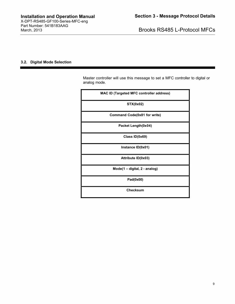
3.2. Digital Mode Selection
Master controller will use this message to set a MFC controller to digital or analog mode.
MAC ID (Targeted MFC controller address)
STX(0x02)
Command Code(0x81 for write)
Packet Length(0x04)
Class ID(0x69)
Instance ID(0x01)
Attribute ID(0x03)
Mode(1 – digital, 2 - analog)
Pad(0x00)
Checksum

Installation and Operation Manual X-DPT-RS485-GF100-Series-MFC-eng Part Number: 541B183AAG March, 2013
10
Section 3 - Message Protocol Details
Brooks RS485 L-Protocol MFCs
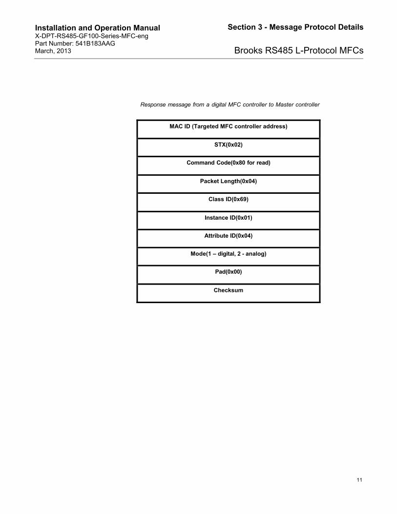
3.3. Query Present Control Mode
Master controller will use this message to query the present control mode.
MAC ID (Targeted MFC controller address)
STX(0x02)
Command Code(0x80 for read)
Packet Length(0x03)
Class ID(0x69)
Instance ID(0x01)
Attribute ID(0x03)
Pad(0x00)
Checksum
Installation and Operation Manual X-DPT-RS485-GF100-Series-MFC-eng Part Number: 541B183AAG March, 2013
11
Section 3 - Message Protocol Details
Brooks RS485 L-Protocol MFCs
Response message from a digital MFC controller to Master controller
MAC ID (Targeted MFC controller address)
STX(0x02)
Command Code(0x80 for read)
Packet Length(0x04)
Class ID(0x69)
Instance ID(0x01)
Attribute ID(0x04)
Mode(1 – digital, 2 - analog)
Pad(0x00)
Checksum

Installation and Operation Manual X-DPT-RS485-GF100-Series-MFC-eng Part Number: 541B183AAG March, 2013
12
Section 3 - Message Protocol Details
Brooks RS485 L-Protocol MFCs
3.4. Freeze Follow
Master controller will use this message to configure a MFC controller to act upon a new set point when received.
MAC ID (Ta rgeted MFC controller address)
STX(0x02)
Command Code(0x81 for write)
Packet Length(0x04)
Class ID(0x69)
Instance ID(0x01)
Attribute ID(0x05)
FreezeFollow(1–Act on new set point immediately)
Pad(0x00)
Checksum

Installation and Operation Manual X-DPT-RS485-GF100-Series-MFC-eng Part Number: 541B183AAG March, 2013
13
Section 3 - Message Protocol Details
Brooks RS485 L-Protocol MFCs
3.5. New Setpoint
Master controller will use this message to send a new set point to a MFC controller.
MAC ID (Targeted MFC controller address)
STX(0x02)
Command Code(0x81 for write)
Packet Length(0x05)
Class ID(0x69)
Instance ID(0x01)
Attribute ID(0xA4)
Data Byte#1(LSB)
Data Byte#2(MSB)
Pad(0x00)
Checksum

Installation and Operation Manual X-DPT-RS485-GF100-Series-MFC-eng Part Number: 541B183AAG March, 2013
14
Section 3 - Message Protocol Details
Brooks RS485 L-Protocol MFCs
3.6. Ramp Time
Master controller will use this message to send a ramp time to a MFC controller. The ramp time is how long the MFC controller should take to reach the final set point from the current set point. The unit is millisecond. A zero ramp time effectively disables the ramping.
Request message from Master controller to a digital MFC controller
MAC ID (Targeted MFC controller address)
STX(0x02)
Command Code(0x81 for write)
Packet Length(0x05)
Class ID(0x6A)
Instance ID(0x01)
Attribute ID(0xA4)
Data Byte#1(LSB)
Data Byte#2(MSB)
Pad(0x00)
Checksum
Installation and Operation Manual X-DPT-RS485-GF100-Series-MFC-eng Part Number: 541B183AAG March, 2013
15
Section 3 - Message Protocol Details
Brooks RS485 L-Protocol MFCs
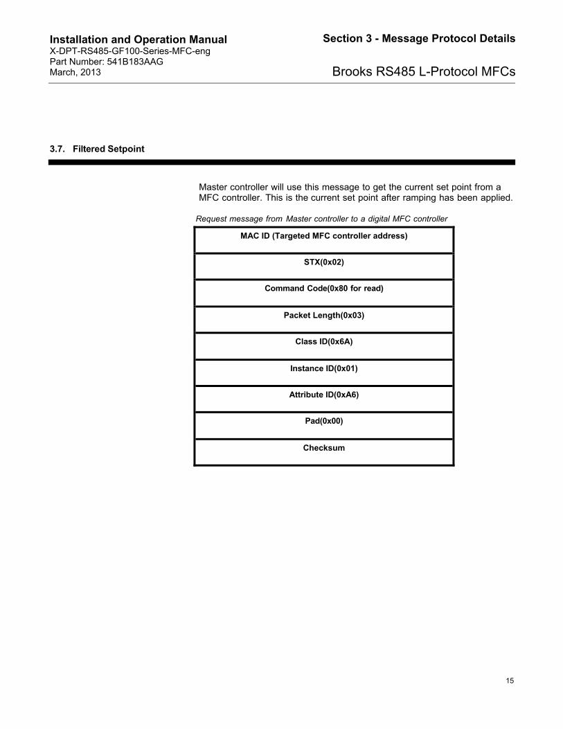
3.7. Filtered Setpoint
Master controller will use this message to get the current set point from a MFC controller. This is the current set point after ramping has been applied.
Request message from Master controller to a digital MFC controller
MAC ID (Targeted MFC controller address)
STX(0x02)
Command Code(0x80 for read)
Packet Length(0x03)
Class ID(0x6A)
Instance ID(0x01)
Attribute ID(0xA6)
Pad(0x00)
Checksum

Installation and Operation Manual X-DPT-RS485-GF100-Series-MFC-eng Part Number: 541B183AAG March, 2013
16
Section 3 - Message Protocol Details
Brooks RS485 L-Protocol MFCs
Response message from a digital MFC controller to Master controller
MAC ID (0 – Master controller)
STX(0x02)
Command Code(0x80 for read)
Packet Length(0x05)
Class ID(0x6A)
Instance ID(0x01)
Attribute ID(0xA6)
Data Byte #1(LSB)
Data Byte #2(MSB)
Pad(0x00)
Checksum
Installation and Operation Manual X-DPT-RS485-GF100-Series-MFC-eng Part Number: 541B183AAG March, 2013
17
Section 3 - Message Protocol Details
Brooks RS485 L-Protocol MFCs
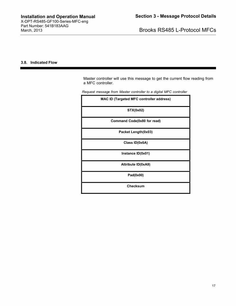
3.8. Indicated Flow
Master controller will use this message to get the current flow reading from a MFC controller.
Request message from Master controller to a digital MFC controller
MAC ID (Targeted MFC controller address)
STX(0x02)
Command Code(0x80 for read)
Packet Length(0x03)
Class ID(0x6A)
Instance ID(0x01)
Attribute ID(0xA9)
Pad(0x00)
Checksum

Installation and Operation Manual X-DPT-RS485-GF100-Series-MFC-eng Part Number: 541B183AAG March, 2013
18
Section 3 - Message Protocol Details
Brooks RS485 L-Protocol MFCs
Response message from a digital MFC controller to Master controller
MAC ID (0 – Master controller)
STX(0x02)
Command Code(0x80 for read)
Packet Length(0x05)
Class ID(0x6A)
Instance ID(0x01)
Attribute ID(0xA9)
Data Byte #1(LSB)
Data Byte #2(MSB)
Pad(0x00)
Checksum

Installation and Operation Manual X-DPT-RS485-GF100-Series-MFC-eng Part Number: 541B183AAG March, 2013
19
Section 3 - Message Protocol Details
Brooks RS485 L-Protocol MFCs
3.9. Valve Drive Current
Master controller will use this message to get the valve drive current.
Request message from Master controller to a digital MFC controller
MAC ID (Targeted MFC controller address)
STX(0x02)
Command Code(0x80 for re ad)
Packet Length(0x03)
Class ID(0x6A)
Instance ID(0x01)
Attribute ID(0xB6)
Pad(0x00)
Checksum

Installation and Operation Manual X-DPT-RS485-GF100-Series-MFC-eng Part Number: 541B183AAG March, 2013
20
Section 3 - Message Protocol Details
Brooks RS485 L-Protocol MFCs
Response message from a digital MFC controller to Master controller
MAC ID (0 – Master controller)
STX(0x02)
Command Code(0x80 for read)
Packet Length(0x05)
Class ID(0x6A)
Instance ID(0x01)
Attribute ID(0xB6)
Data Byte #1(LSB)
Data Byte #2(MSB)
Pad(0x00)
Checksum
Installation and Operation Manual X-DPT-RS485-GF100-Series-MFC-eng Part Number: 541B183AAG March, 2013
21
Section 3 - Message Protocol Details
Brooks RS485 L-Protocol MFCs
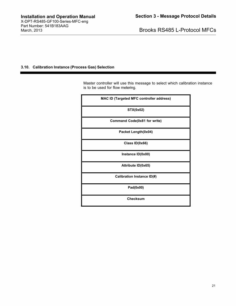
3.10. Calibration Instance (Process Gas) Selection
Master controller will use this message to select which calibration instance is to be used for flow metering.
MAC ID (Targeted MFC controller address)
STX(0x02)
Command Code(0x81 for write)
Packet Length(0x04)
Class ID(0x66)
Instance ID(0x00)
Attribute ID(0x65)
Calibration Instance ID(#)
Pad(0x00)
Checksum

Installation and Operation Manual X-DPT-RS485-GF100-Series-MFC-eng Part Number: 541B183AAG March, 2013
22
Section 3 - Message Protocol Details
Brooks RS485 L-Protocol MFCs
3.11. Query for Calibration Instance (Process Gas) Selection
Master controller will use this message to query the selected calibration instance, which is currently being used for flow metering.
Request message from Master controller to a digital MFC controller
MAC ID (Targeted MFC controller address)
STX(0x02)
Command Code(0x80 for read)
Packet Length(0x03)
Class ID(0x66)
Instance ID(0x00)
Attribute ID(0x65)
Pad(0x00)
Checksum

Installation and Operation Manual X-DPT-RS485-GF100-Series-MFC-eng Part Number: 541B183AAG March, 2013
23
Section 3 - Message Protocol Details
Brooks RS485 L-Protocol MFCs
Response message from a digital MFC controller to Master controller
MAC ID (0 – Master controller)
STX(0x02)
Command Code(0x80 for read)
Packet Length(0x04)
Class ID(0x66)
Instance ID(0x00)
Attribute ID(0x65)
Calibration Instance ID(#)
Pad(0x00)
Checksum

Installation and Operation Manual X-DPT-RS485-GF100-Series-MFC-eng Part Number: 541B183AAG March, 2013
24
Section 3 - Message Protocol Details
Brooks RS485 L-Protocol MFCs
3.12. Query for Available Calibration Instances (Process Gases)
Master controller will use this message to query available number of calibration instances.
Request message from Master controller to a digital MFC controller
MAC ID (Targeted MFC controller address)
STX(0x02)
Command Code(0x80 for read)
Packet Length(0x03)
Class ID(0x66)
Instance ID(0x00)
Attribute ID(0xA0)
Pad(0x00)
Checksum

Installation and Operation Manual X-DPT-RS485-GF100-Series-MFC-eng Part Number: 541B183AAG March, 2013
25
Section 3 - Message Protocol Details
Brooks RS485 L-Protocol MFCs
Response message from a digital MFC controller to Master controller
MAC ID (0 – Master controller)
STX(0x02)
Command Code(0x80 for read)
Packet Length(0x04)
Class ID(0x66)
Instance ID(0x00)
Attribute ID(0xA0)
Available # Of Calibration Instances
Pad(0x00)
Checksum

Installation and Operation Manual X-DPT-RS485-GF100-Series-MFC-eng Part Number: 541B183AAG March, 2013
26
Section 3 - Message Protocol Details
Brooks RS485 L-Protocol MFCs
3.13. Auto Zero Enable/Disable
Master controller will use this message to enable auto zero function.
MAC ID (Targeted MFC controlle r address)
STX(0x02)
Command Code(0x81 for write)
Packet Length(0x04)
Class ID(0x68)
Instance ID(0x01)
Attribute ID(0xA5)
>0 for enable, = 0 for disable
Pad(0x00)
Checksum

Installation and Operation Manual X-DPT-RS485-GF100-Series-MFC-eng Part Number: 541B183AAG March, 2013
27
Section 3 - Message Protocol Details
Brooks RS485 L-Protocol MFCs
3.14. Requested Zero Enable
Master controller will use this message to enable requested function.
MAC ID (Targeted MFC controller address)
STX(0x02)
Command Code(0x81 for write)
Packet Length(0x04)
Class ID(0x68)
Instance ID(0x01)
Attribute ID(0xBA)
1 for enable
Pad(0x00)
Checksum

Installation and Operation Manual X-DPT-RS485-GF100-Series-MFC-eng Part Number: 541B183AAG March, 2013
28
Section 3 - Message Protocol Details
Brooks RS485 L-Protocol MFCs
3.15. Query for Requested Zero Status
Master controller will use this message to query if the requested zero function has been completed.
Request message from Master controller to a digital MFC controller
MAC ID (Targeted MFC controller address)
STX(0x02)
Command Code(0x80 for read)
Packet Length(0x03)
Class ID(0x68)
Instance ID(0x01)
Attribute ID(0xBA)
Pad(0x00)
Checksum

Installation and Operation Manual X-DPT-RS485-GF100-Series-MFC-eng Part Number: 541B183AAG March, 2013
29
Section 3 - Message Protocol Details
Brooks RS485 L-Protocol MFCs
Response message from a digital MFC controller to Master controller
MAC ID (0 – Master controller)
STX(0x02)
Command Code(0x80 for read)
Packet Length(0x04)
Class ID(0x68)
Instance ID(0x01)
Attribute ID(0xBA)
0: completed, 1: in progress
Pad(0x00)
Checksum
Installation and Operation Manual X-DPT-RS485-GF100-Series-MFC-eng Part Number: 541B183AAG March, 2013
30
Section 3 - Message Protocol Details
Brooks RS485 L-Protocol MFCs
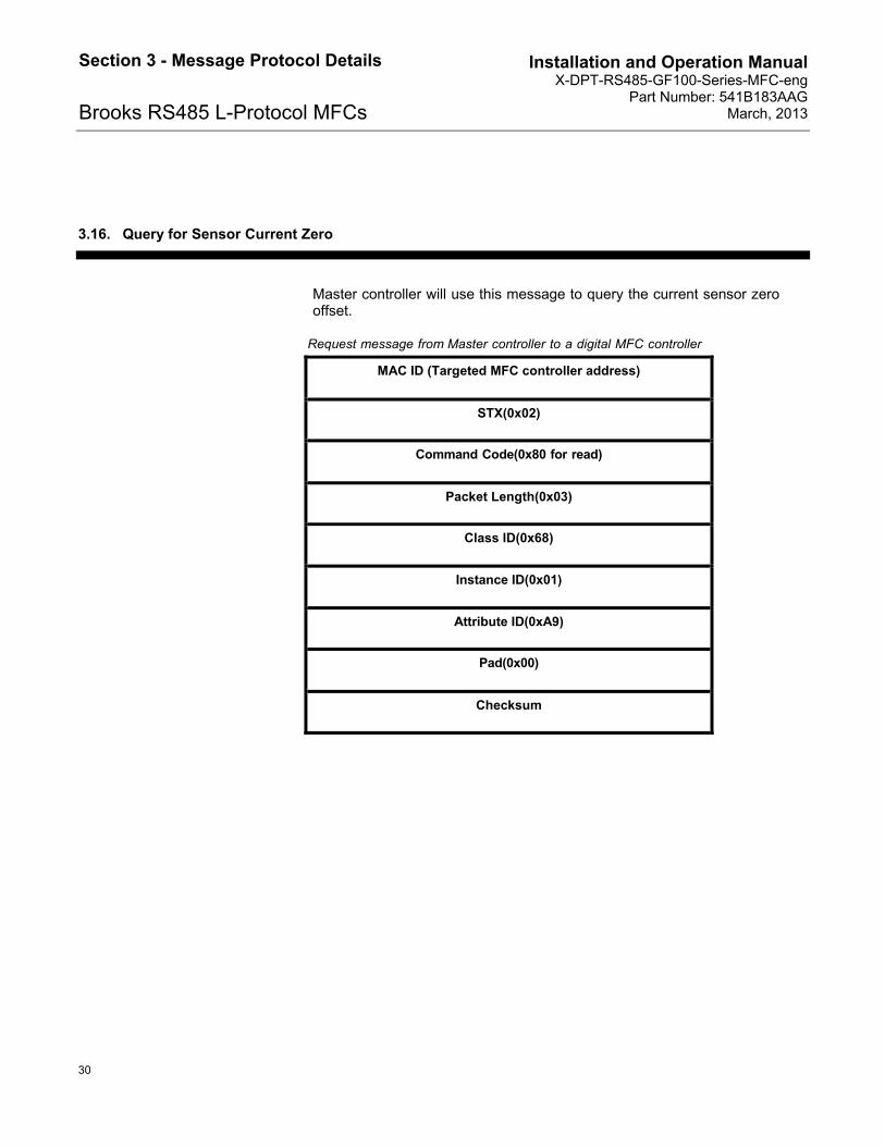
3.16. Query for Sensor Current Zero
Master controller will use this message to query the current sensor zero offset.
Request message from Master controller to a digital MFC controller
MAC ID (Targeted MFC controller address)
STX(0x02)
Command Code(0x80 for read)
Packet Length(0x03)
Class ID(0x68)
Instance ID(0x01)
Attribute ID(0xA9)
Pad(0x00)
Checksum

Installation and Operation Manual X-DPT-RS485-GF100-Series-MFC-eng Part Number: 541B183AAG March, 2013
31
Section 3 - Message Protocol Details
Brooks RS485 L-Protocol MFCs
Response message from a digital MFC controller to Master controller
MAC ID (0 – Master controller)
STX(0x02)
Command Code(0x80 for read)
Packet Length(0x05)
Class ID(0x68)
Instance ID(0x01)
Attribute ID(0xA9)
Data Byte #1(LSB)
Data Byte #2(MSB)
Pad(0x00)
Checksum

Installation and Operation Manual X-DPT-RS485-GF100-Series-MFC-eng Part Number: 541B183AAG March, 2013
32
Section 3 - Message Protocol Details
Brooks RS485 L-Protocol MFCs
3.17. Query for Sensor Reference Zero
Master controller will use this message to query the sensor reference zero offset.
Request message from Master controller to a digital MFC controller
MAC ID (Targeted MFC controller address)
STX(0x02)
Command Code(0x80 for read)
Packet Length(0x03)
Class ID(0x68)
Instance ID(0x01)
Attribute ID(0xAA)
Pad(0x00)
Checksum

Installation and Operation Manual X-DPT-RS485-GF100-Series-MFC-eng Part Number: 541B183AAG March, 2013
33
Section 3 - Message Protocol Details
Brooks RS485 L-Protocol MFCs
Response message from a digital MPC controller to Master controller
MAC ID (0 – Master controller)
STX(0x02)
Command Code(0x80 for read)
Packet Length(0x05)
Class ID(0x68)
Instance ID(0x01)
Attribute ID(0xAA)
Data Byte #1(LSB)
Data Byte #2(MSB)
Pad(0x00)
Checksum

Installation and Operation Manual X-DPT-RS485-GF100-Series-MFC-eng Part Number: 541B183AAG March, 2013
34
Section 3 - Message Protocol Details
Brooks RS485 L-Protocol MFCs
3.18. Set Sensor Reference Zero
Master controller will use this message to set sensor reference zero offset.
MAC ID (Targeted MFC controller address)
STX(0x02)
Command Code(0x81 for write)
Packet Length(0x05)
Class ID(0x68)
Instance ID(0x01)
Attribute ID(0xAA)
Data Byte#1(LSB)
Data Byte#2(MSB)
Pad(0x00)
Checksum

Installation and Operation Manual X-DPT-RS485-GF100-Series-MFC-eng Part Number: 541B183AAG March, 2013
35
Section 3 - Message Protocol Details
Brooks RS485 L-Protocol MFCs
3.19. Set Default Control Mode
Master controller will use this message to set MFC control mode when first powered up.
MAC ID (Targeted MFC controller address)
STX(0x02)
Command Code(0x81 for write)
Packet Length(0x04)
Class ID(0x69)
Instance ID(0x01)
Attribute ID(0x04)
Mode(1 – digital, 2 - analog)
Pad(0x00)
Checksum

Installation and Operation Manual X-DPT-RS485-GF100-Series-MFC-eng Part Number: 541B183AAG March, 2013
36
Section 3 - Message Protocol Details
Brooks RS485 L-Protocol MFCs
3.20. Query Default Control Mode
Master controller will use this message to query the MFC wakeup control mode.
MAC ID (Targeted MFC controller address)
STX(0x02)
Comma nd Code(0x80 for read)
Packet Length(0x03)
Class ID(0x69)
Instance ID(0x01)
Attribute ID(0x04)
Pad(0x00)
Checksum
Installation and Operation Manual X-DPT-RS485-GF100-Series-MFC-eng Part Number: 541B183AAG March, 2013
37
Section 3 - Message Protocol Details
Brooks RS485 L-Protocol MFCs
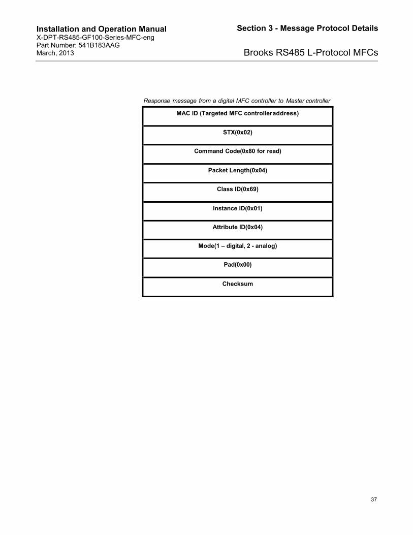
Response message from a digital MFC controller to Master controller
MAC ID (Targeted MFC controlleraddress)
STX(0x02)
Command Code(0x80 for read)
Packet Length(0x04)
Class ID(0x69)
Instance ID(0x01)
Attribute ID(0x04)
Mode(1 – digital, 2 - analog)
Pad(0x00)
Checksum

Installation and Operation Manual X-DPT-RS485-GF100-Series-MFC-eng Part Number: 541B183AAG March, 2013
38
Section 3 - Message Protocol Details
Brooks RS485 L-Protocol MFCs
THIS PAGE WAS INTENTIONALLY
LEFT BLANK
Installation and Operation Manual X-DPT-RS485-GF100-Series-MFC-eng Part Number: 541B183AAG March, 2013
39
Section 4 - Software Design Requirement
Brooks RS485 L-Protocol MFCs
4. Software Design Requirement
4.1. Normal Transaction Scenarios
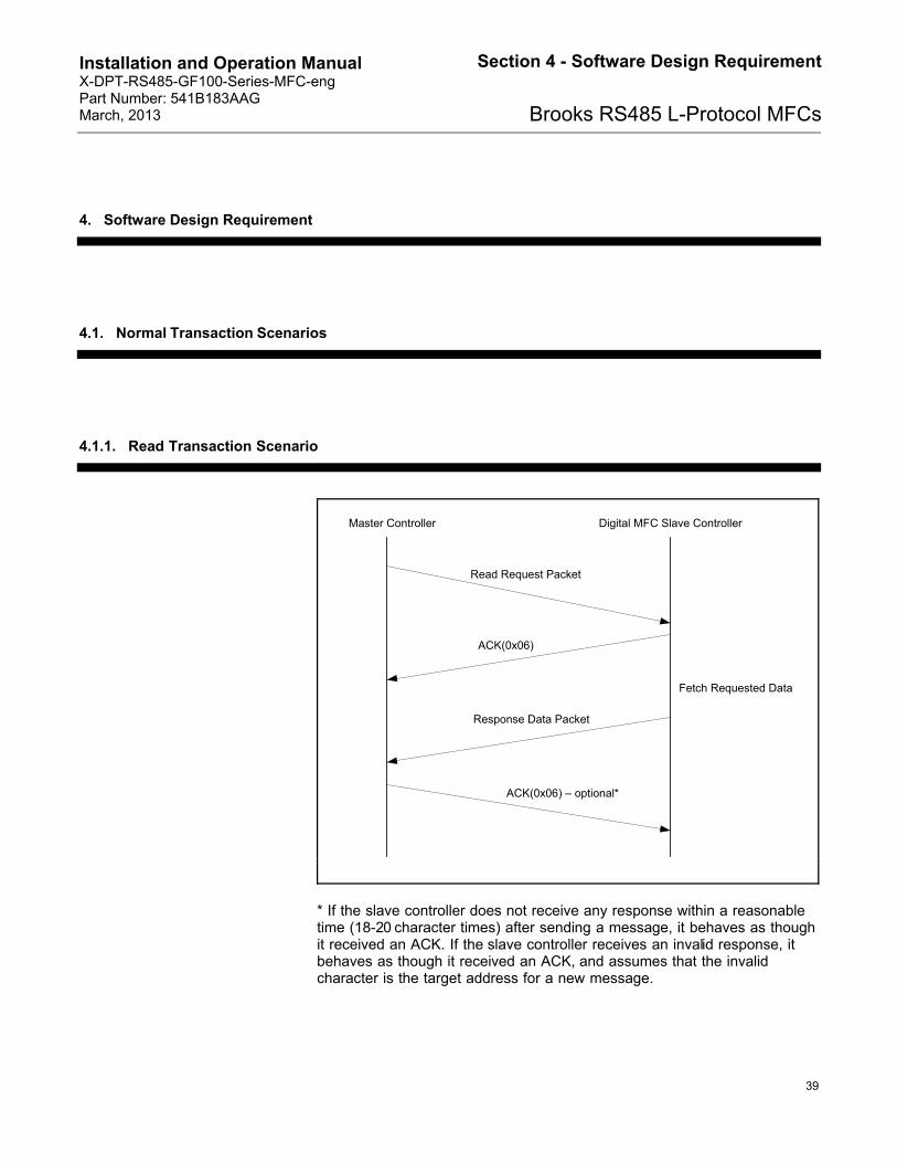
4.1.1. Read Transaction Scenario
Read Request Packet
ACK(0x06)
Response Data Packet
ACK(0x06) – optional*
Master Controller
Fetch Requested Data
Digital MFC Slave Controller
* If the slave controller does not receive any response within a reasonable time (18-20 character times) after sending a message, it behaves as though it received an ACK. If the slave controller receives an invalid response, it behaves as though it received an ACK, and assumes that the invalid character is the target address for a new message.
Installation and Operation Manual X-DPT-RS485-GF100-Series-MFC-eng Part Number: 541B183AAG March, 2013
40
Section 4 - Software Design Requirement
Brooks RS485 L-Protocol MFCs
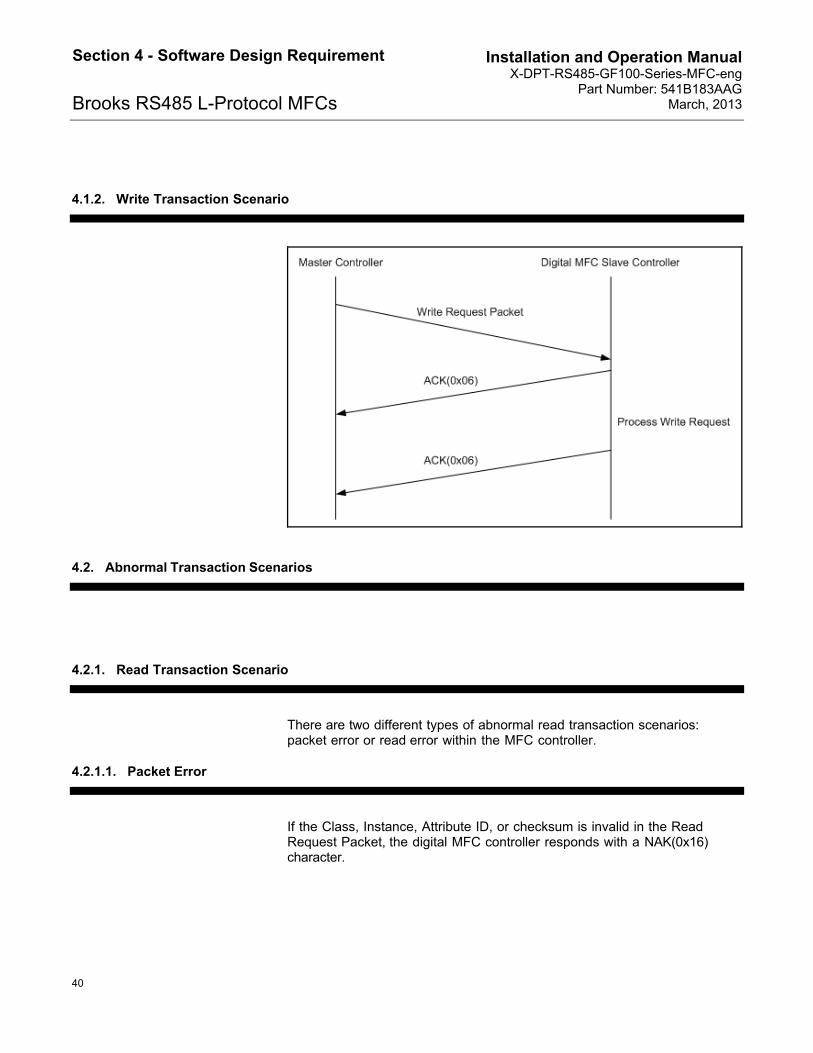
4.1.2. Write Transaction Scenario
4.2. Abnormal Transaction Scenarios
4.2.1. Read Transaction Scenario
There are two different types of abnormal read transaction scenarios: packet error or read error within the MFC controller.
4.2.1.1. Packet Error
If the Class, Instance, Attribute ID, or checksum is invalid in the Read Request Packet, the digital MFC controller responds with a NAK(0x16) character.

Installation and Operation Manual X-DPT-RS485-GF100-Series-MFC-eng Part Number: 541B183AAG March, 2013
41
Section 4 - Software Design Requirement
Brooks RS485 L-Protocol MFCs
4.2.1.2. Read Error
If any errors occur within the MFC controller after the first ACK is sent (no packet errors), a NAK (0x16) will be sent to indicate an execution error.
Read Request Packet
ACK(0x06)
Master Controller Digital MFC Slave Controller
NAK(0x16)
Failed to Process Read Request
Installation and Operation Manual X-DPT-RS485-GF100-Series-MFC-eng Part Number: 541B183AAG March, 2013
42
Section 4 - Software Design Requirement
Brooks RS485 L-Protocol MFCs
4.2.2. Write Transaction Scenario
There are two different types of abnormal write transaction scenarios: packet error or write error within the MFC controller.
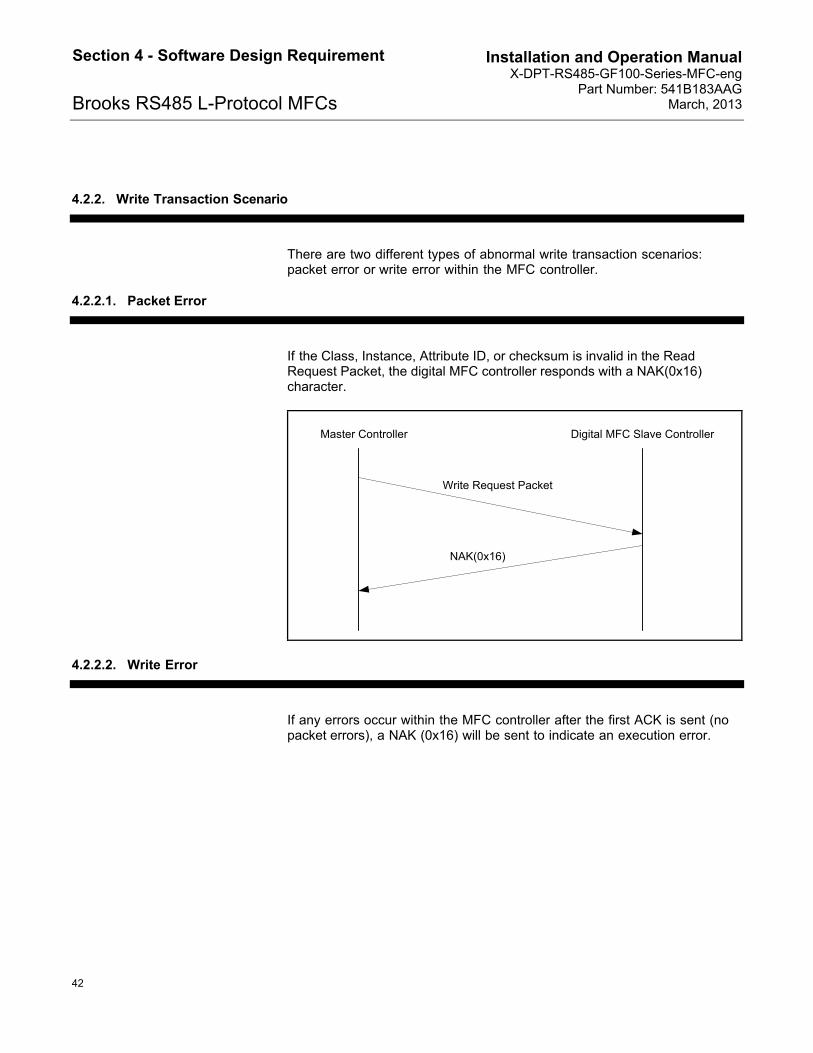
4.2.2.1. Packet Error
If the Class, Instance, Attribute ID, or checksum is invalid in the Read Request Packet, the digital MFC controller responds with a NAK(0x16) character.
Write Request Packet
NAK(0x16)
Master Controller Digital MFC Slave Controller
4.2.2.2. Write Error
If any errors occur within the MFC controller after the first ACK is sent (no packet errors), a NAK (0x16) will be sent to indicate an execution error.

Installation and Operation Manual X-DPT-RS485-GF100-Series-MFC-eng Part Number: 541B183AAG March, 2013
43
Section 4 - Software Design Requirement
Brooks RS485 L-Protocol MFCs
4.3. Protocol Timing
Devices on the RS485 bus distinguish address characters from other packet characters by maintaining an idle timer. This timer is started at the end of each received character, and expires if the next character does not arrive within two bytes times (20 bit times). If the timer expires, the device assumes that the message has ended, and the next character received will be either a target address, or a response indicating the acceptance of the previous packet (ACK or NAK). Thus it is vital that devices on the bus not insert idle gaps of 1 character time or more within a packet. A target device can also assume that an error has occurred if a new character is expected and does not arrive within 2 character times of the preceding character’s arrival.
Each transaction on the bus begins when the Master controller transmits a request packet on the bus, following an idle gap of at least 1 character time. The specified slave MFC controller replies quickly with an ACK character (0x06) to indicate that it has received the packet correctly. After the request message is processed, the specified controller responds with a reply message or an ACK.
Since the current supported messages are simple and small, the Master controller expects that the entire response to the request message to be completed by the MFC controller within 5 ms. If the Master controller does not receive all response characters (ACK+ACK (2 bytes) for write request, ACK + response packet (11 or 12 bytes)) within 5ms, it assumes that an error has occurred and up to 3 retries are performed automatically.

Installation and Operation Manual X-DPT-RS485-GF100-Series-MFC-eng Part Number: 541B183AAG March, 2013
44
Section 4 - Software Design Requirement
Brooks RS485 L-Protocol MFCs
4.4. Message Sequence between Master Controller and a MFC Slave Controller
Query for MAC ID
ACK
MAC ID Reply
Digital Mode Selection
ACK
ACK
Freeze Follow
ACK
ACK
NewSetpoint and/or Ramp Time
ACK
ACK
IndicatedFlow
IndicatedFlow Reply
ACK
Initialization
If a new set point has been specified
Perform every loop
Master Controller MFC Slave Controller

Installation and Operation Manual X-DPT-RS485-GF100-Series-MFC-eng Part Number: 541B183AAG March, 2013
45
Section 4 - Software Design Requirement
Brooks RS485 L-Protocol MFCs
4.5. MFC New Setpoint Conversion
The NewSetpoint request takes values in the range of 0x4000 to 0xC000 which represent set points between 0% and 100% full scale. The linear relationship between Full Scale set points and NewSetpoint is demonstrated in the following table:
Full Scale % set point NewSetpoint Valve(Hex)
0.0 4000
25.0 6000
50.0 8000
75.0 A000
99.0 BEB8
100.0 C000
The “NewSetpoint” value may be calculated from the full scale percent value by:
“NewSetpoint” = (327.68 * full scale %) + 16,384
or
“NewSetpoint” = ((0xC000-0x4000)/100 * full scale %) + 0x4000
Note that at the communication level all values are sent in binary format. The decimal and hexadecimal formats shown above are for convenience.
4.6. Sensor Zero Filter
The digital MFC controller should provide sensor zero filter to support correction for reasonably stable offsets in the gas flow sensor. The actual flow reading (IndicatedFlow) should be derived by subtracting SensorCurrentZero from each sensor measurement. SensorCurrentZero can be updated under two conditions, described in the following sub-sections.

Installation and Operation Manual X-DPT-RS485-GF100-Series-MFC-eng Part Number: 541B183AAG March, 2013
46
Section 4 - Software Design Requirement
Brooks RS485 L-Protocol MFCs
4.6.1. Requested Zero
When the requested zero command is issued by Master controller, the digital MFC controller should close the flow meter valve and wait until the sensor output is stabilized (typically 90 seconds). Then the requested zero function can be started and the SensorCurrentZero is to be updated through the entire process. At the end of the process, SensorReferenceZero is to be set to SensorCurrentZero. If Auto Zero function is never enabled, the SensorCurrentZero is always equal to SensorRe ferenceZero . For flexibility the SensorReferenceZero can also be set by the Master controller.
Due to the long duration to execute the "Enable requested Zero" command, the MFC will not return an ACK when process is completed. Instead, an ACK is sent to acknowledge start of execution. During the process time, the MFC is in an "In Progress" state. While in the "In Progress" state, the MFC will only accept commands from the "Query Requested Zero Status" command, all other request to the MFC can be ignored
4.6.2. Auto Zero
Auto zero process can be started under the following condition:
Auto Zero Enable has been issued by Master controller
The digital MFC is in OFF mode
Once the above condition has been true for a specified delay (typically 90 seconds), auto zero process can be started at the specified rate (typically 10 times per second) and the SensorCurrentZero is to be updated through the entire process.
During the auto zero calculations, the digital MFC controller can use SensorReferenceZero to check against the calculated results. If the difference between SensorReferenceZero and the calculated result is beyond a specified limit, exception can be raised within the digital MFC controller.

Installation and Operation Manual X-DPT-RS485-GF100-Series-MFC-eng Part Number: 541B183AAG March, 2013
47
Section 4 - Software Design Requirement
Brooks RS485 L-Protocol MFCs
4.7. Calibration Instances
Each calibration instance contains values needed by flow meter to calculate the actual gas flow rate for a particular process gas and flow range from sensor readings. This protocol allows Master controller to query for number of available calibration instances supported by the digital MFC controller and select a calibration instance for digital MFC operation and calculation. The detailed calibration instance internal setup is not supported through this interface and must be programmed through local MFC controller.
4.8. Analog / Digital Mode
The default mode for the MFC is set to Analog Mode. MFC's can be switch to Digital Mode with the "Digital Mode Selection" command as soon as communication is established

Installation and Operation Manual X-DPT-RS485-GF100-Series-MFC-eng Part Number: 541B183AAG March, 2013
48
Section 4 - Software Design Requirement
Brooks RS485 L-Protocol MFCs
THIS PAGE WAS INTENTIONALLY
LEFT BLANK

Installation and Operation Manual X-DPT-RS485-GF100-Series-MFC-eng Part Number: 541B183AAG March, 2013
49
Section 5 - Advanced Diagnostics (GF135 Only)
Brooks RS485 L-Protocol MFCs
5. Advanced Diagnostics (GF135 Only)
5.1. New Communication Protocol Overview
5.1.1. Objectives and Problem Statement
Through the years, issues found in the field on Brooks MFCs have been very difficult to troubleshoot due to lack of information given to failure analysis teams. Issues that are random in occurrence and are specific to the field setup are the most difficult to reproduce therefore troubleshooting takes longer.
This new communication capability will enable the device to perform a series of self validation at regular interval and report its status to the tool software. Some of the self validation will require at least knowing the state of certain part of the tool over which the device typically had neither control nor access. The capabilities of the GF135 will enable short interval control of the upstream isolation valve in a manner consistent with good safety practices.
Those capabilities do not exist in any protocol currently in use in the field.
5.1.2. Protocol Description
The communication protocol shall be implemented over RS485 physical layer.
The protocol shall be able to handle the following type of communications between the device and the tool:
Tool request for Commissioning status
Tool request for valve leak status, ROD measurements
These are the minimum requirements to support advanced diagnostics.

Installation and Operation Manual X-DPT-RS485-GF100-Series-MFC-eng Part Number: 541B183AAG March, 2013
50
Appendix - Tool - Device Communication
Brooks RS485 L-Protocol MFCs
5.2. Specific Requirements
5.2.1. Introduction
The following requirements are a subset of Brooks’ new communication protocol definition.
5.2.2. Advanced Protocol
The advanced communication protocol is more fully defined in GF135-SRS-011.
5.2.3. New Attributes
Note: Those attributes are valid as of the date of writing. Attribute ID are subject to change and new attributes will likely be added by the time this document is finalized.
New attributes for the advanced diagnostic:
Attribute Access Class Instance Att. ID Values
isolation valve status READ ONLY 177 1 3 0: Upstream open
1: Upstream closed
ROD delay Read/Write 177 1 20 Delay before first ROD measurement after a setpoint change (seconds).
Minimum = default = 4 sec.
ROD interval Read/Write 177 1 21 Interval between ROD measurement when setpoint is constant (seconds).
Minimum = 5 sec. Default = 10 sec.
ROD enable Default flag
Read/Write 177 1 55 0: ROD is disabled
1: ROD is enabled
Non Volatile. Copied to Attribute 62 at power up.
Default = Enabled

Installation and Operation Manual X-DPT-RS485-GF100-Series-MFC-eng Part Number: 541B183AAG March, 2013
51
Section 5 - Advanced Diagnostics (GF135 Only)
Brooks RS485 L-Protocol MFCs
Attribute Access Class Instance Att. ID Values
ROD Error Status READ ONLY 177 1 56 0: ROD Error (attribute 11) is not valid
1: ROD Error (attribute 11) is valid
Valve Leak status READ ONLY 177 1 57 0: Valve Leak Meas. is not valid
1: Valve Leak Meas. is valid
Valve Leak value READ ONLY 177 1 59 Float, fraction of configured range
ROD Current Setpoint READ ONLY 177 1 60 Current setpoint at which the ROD is being measured (see attribute 11) (fraction of configured range)
ROD error READ ONLY 177 1 61 ROD measured flow change (from baseline) in % SP for the current setpoint. Same as ROD error N.
ROD enable flag Read/Write 177 1 62 0: ROD is disabled
1: ROD is enabled
Volatile
Commissioning status Read/Write 103 n 132 0: Not done or failed
1: Commissioning was successful
ROD 0 Status READ ONLY 177 1 70 0: ROD Error 0 is not valid
1: ROD Error 0 is valid
ROD 1 Status READ ONLY 177 1 71 0: ROD Error 1 is not valid
1: ROD Error 1 is valid
ROD 2 Status READ ONLY 177 1 72 0: ROD Error 2 is not valid
1: ROD Error 2 is valid
ROD 3 Status READ ONLY 177 1 73 0: ROD Error 3 is not valid
1: ROD Error 3 is valid
ROD 4 Status READ ONLY 177 1 74 0: ROD Error 4 is not valid
1: ROD Error 4 is valid
ROD 5 Status READ ONLY 177 1 75 0: ROD Error 5 is not valid
1: ROD Error 5 is valid
ROD 6 Status READ ONLY 177 1 76 0: ROD Error 6 is not valid
1: ROD Error 6 is valid
ROD 7 Status READ ONLY 177 1 77 0: ROD Error 7 is not valid
1: ROD Error 7 is valid
ROD 8 Status READ ONLY 177 1 78 0: ROD Error 8 is not valid
1: ROD Error 8 is valid
ROD 9 Status READ ONLY 177 1 79 0: ROD Error 9 is not valid
1: ROD Error 9 is valid
ROD 10 Status READ ONLY 177 1 80 0: ROD Error 10 is not valid
1: ROD Error 10 is valid

Installation and Operation Manual X-DPT-RS485-GF100-Series-MFC-eng Part Number: 541B183AAG March, 2013
52
Appendix - Tool - Device Communication
Brooks RS485 L-Protocol MFCs
Attribute Access Class Instance Att. ID Values
ROD 11 Status READ ONLY 177 1 81 0: ROD Error 11 is not valid
1: ROD Error 11 is valid
ROD 12 Status READ ONLY 177 1 82 0: ROD Error12 is not valid
1: ROD Error 12 is valid
ROD 13 Status READ ONLY 177 1 83 0: ROD Error 13 is not valid
1: ROD Error 13 is valid
ROD 14 Status READ ONLY 177 1 84 0: ROD Error 14 is not valid
1: ROD Error 14 is valid
ROD 15 Status READ ONLY 177 1 85 0: ROD Error 15 is not valid
1: ROD Error 15 is valid
ROD 16 Status READ ONLY 177 1 86 0: ROD Error 16 is not valid
1: ROD Error 16 is valid
ROD 17 Status READ ONLY 177 1 87 0: ROD Error 17 is not valid
1: ROD Error 17 is valid
ROD 18 Status READ ONLY 177 1 88 0: ROD Error 18 is not valid
1: ROD Error 18 is valid
ROD 19 Status READ ONLY 177 1 89 0: ROD Error 19 is not valid
1: ROD Error 19 is valid
ROD Error 0 READ ONLY 177 1 90 Float, Avg. error for setpoint 0-5%
ROD Error 1 READ ONLY 177 1 91 Float, Avg. error for setpoint 5-10%
ROD Error 2 READ ONLY 177 1 92 Float, Avg. error for setpoint 10-15%
ROD Error 3 READ ONLY 177 1 93 Float, Avg. error for setpoint 15-20%
ROD Error 4 READ ONLY 177 1 94 Float, Avg. error for setpoint 20-25%
ROD Error 5 READ ONLY 177 1 95 Float, Avg. error for setpoint 25-30%
ROD Error 6 READ ONLY 177 1 96 Float, Avg. error for setpoint 30-35%
ROD Error 7 READ ONLY 177 1 97 Float, Avg. error for setpoint 35-40%
ROD Error 8 READ ONLY 177 1 98 Float, Avg. error for setpoint 40-45%
ROD Error 9 READ ONLY 177 1 99 Float, Avg. error for setpoint 45-50%
ROD Error 10 READ ONLY 177 1 100 Float, Avg. error for setpoint 50-55%
ROD Error 11 READ ONLY 177 1 101 Float, Avg. error for setpoint 55-60%
ROD Error 12 READ ONLY 177 1 102 Float, Avg. error for setpoint 60-65%
ROD Error 13 READ ONLY 177 1 103 Float, Avg. error for setpoint 65-70%
ROD Error 14 READ ONLY 177 1 104 Float, Avg. error for setpoint 70-75%
ROD Error 15 READ ONLY 177 1 105 Float, Avg. error for setpoint 75-80%
ROD Error 16 READ ONLY 177 1 106 Float, Avg. error for setpoint 80-85%

Installation and Operation Manual X-DPT-RS485-GF100-Series-MFC-eng Part Number: 541B183AAG March, 2013
53
Section 5 - Advanced Diagnostics (GF135 Only)
Brooks RS485 L-Protocol MFCs
Attribute Access Class Instance Att. ID Values
ROD Error 17 READ ONLY 177 1 107 Float, Avg. error for setpoint 85-90%
ROD Error 18 READ ONLY 177 1 108 Float, Avg. error for setpoint 90-95%
ROD Error 19 READ ONLY 177 1 109 Float, Avg. error for setpoint 95-100%
The following set of attributes is required for the data logging and trending:
Attribute Access Class Instance Att. ID Values
Time Synchronization
WRITE ONLY 0x43 (67) 1 TBD Time and date information
Not implemented
Data Request READ ONLY 0x41 (65) 1 TBD Trending information
Not implemented
5.3. Tool – Device Communication
The following items need to be addressed with the customer to define the new advanced diagnostic protocol:
Tool to provide status (e.g. isolation valve status upstream and downstream)
Some operations require knowing the status of the isolation valves on both sides of the device. The tool shall provide this information by writing to the isolation valve status attribute whenever the status changes.
Note: At this time, this is not implemented on the customer tool software.
Request from the device to the tool to modify the tool status (e.g. Operating the isolation valves at the request of the MFC)
Some operations require a specific state of the isolation valves on both sides of the device. The tool shall read the isolation valve request attribute on a schedule TBD and satisfy the request of the MFC.
Note: At this time, this is not implemented on the customer tool software.

Installation and Operation Manual X-DPT-RS485-GF100-Series-MFC-eng Part Number: 541B183AAG March, 2013
54
Appendix - Tool - Device Communication
Brooks RS485 L-Protocol MFCs
Time synchronization
In order to provide accurate data logging for the trending diagnostic, the tool will need to provide accurate time synchronization. The MFC is capable of running a real time clock, so only occasional synchronization is required (at least once per power on cycle)
Note: At this time, this is not implemented on the customer tool software.
Request from the tool for some trending information
Data can be logged at regular interval and time stamped using the time information
Data can be retrieved by the customer to provide long term trend (e.g. zero information logged once per week)
Note: At this time, this is only supported via the diagnostic port.

Installation and Operation Manual X-DPT-RS485-GF100-Series-MFC-eng Part Number: 541B183AAG March, 2013
55
Appendix - Tool - Device Communication
Brooks RS485 L-Protocol MFCs
6. Appendix: Tool - Device Communication
MFC's can have software configurable MAC ID's by sending the "Set MAC ID" command to the current MFC controller address or the default address (0xFF).
Master controller will use this message to set the MAC ID of a MFC.
Set message from Master controller to a digital MFC controller
MAC ID (Targeted MFC controller address)
STX(0x02)
Command Code(0x81 for write)
Packet Length(0x04)
Class ID(0x03)
Instance ID(0x01)
Attribute ID(0x01)
Data(0x33~0x47)
Pad(0x00)
Checksum

Installation and Operation Manual X-DPT-RS485-GF100-Series-MFC-eng Part Number: 541B183AAG March, 2013
56
Appendix - Tool - Device Communication
Brooks RS485 L-Protocol MFCs
THIS PAGE WAS INTENTIONALLY
LEFT BLANK

Installation and Operation Manual X-DPT-RS485-GF100-Series-MFC-eng Part Number: 541B183AAG March, 2013
Brooks RS485 L-Protocol MFCs
THIS PAGE WAS INTENTIONALLY
LEFT BLANK

Installation and Operation Manual X-DPT-RS485-GF100-Series-MFC-eng Part Number: 541B183AAG March, 2013
Brooks RS485 L-Protocol MFCs
LIMITED WARRANTY
Seller warrants that the Goods manufactured by Seller will be free from defects in materials or workmanship under normal use and service and that the Software will execute the programming instructions provided by Seller until the expiration of the earlier of twelve (12) months from the date of initial installation or eighteen (18) months from the date of shipment by Seller. Products purchased by Seller from a third party for resale to Buyer (“Resale Products”) shall carry only the warranty extended by the original manufacturer. All replacements or repairs necessitated by inadequate preventive maintenance, or by normal wear and usage, or by fault of Buyer, or by unsuitable power sources or by attack or deterioration under unsuitable environmental conditions, or by abuse, accident, alteration, misuse, improper installation, modification, repair, storage or handling, or any other cause not the fault of Seller are not covered by this limited warranty, and shall be at Buyer’s expense. Goods repaired and parts replaced during the warranty period shall be in warranty for the remainder of the original warranty period or ninety (90) days, whichever is longer. This limited warranty is the only warranty made by Seller and can be amended only in a writing signed by an authorized representative of Seller. BROOKS SERVICE AND SUPPORT
Brooks is committed to assuring all of our customers receive the ideal flow solution for their application, along with outstanding service and support to back it up. We operate first class repair facilities located around the world to provide rapid response and support. Each location utilizes primary standard calibration equipment to ensure accuracy and reliability for repairs and recalibration and is certified by our local Weights and Measures Authorities and traceable to the relevant International Standards.
Visit www.BrooksInstrument.com to locate the service location nearest to you. START-UP SERVICE AND IN-SITU CALIBRATION
Brooks Instrument can provide start-up service prior to operation when required. For some process applications, where ISO-9001 Quality Certification is important, it is mandatory to verify and/or (re)calibrate the products periodically. In many cases this service can be provided under in-situ conditions, and the results will be traceable to the relevant international quality standards. CUSTOMER SEMINARS AND TRAINING Brooks Instrument can provide customer seminars and dedicated training to engineers, end users and maintenance persons. Please contact your nearest sales representative for more details. HELP DESK In case you need technical assistance: USA 888 275 8946 Korea +82 31 708 2521 Netherlands +31 (0) 318 549290 Taiwan +886 3 5590 988 Germany +49 351 215 2040 China +86 21 5079 8828 Japan +81 3 5633 7100 Singapore +6297 9741 Due to Brooks Instrument's commitment to continuous improvement of our products, all specifications are subject to change without notice. TRADEMARKS Brooks . Brooks Instrument, LLC DeviceNet Open DeviceNet Vendors Association, Inc.