compatibility list blue’log xm / xc - meteocontrol.com · connections rs485 bus cabling the...
TRANSCRIPT
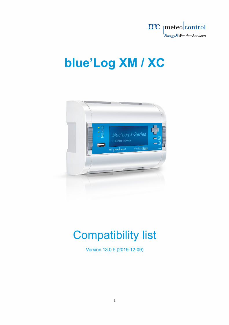
blue’Log XM / XC
Compatibility listVersion 13.0.5 (2019-12-09)
1
CopyrightCopyright for this document remains with the manufacturer. No part of this document may be reproduced or edited, duplicated or
distributed in any form or by any means without prior written consent of meteocontrol GmbH.
Compensation shall be payable in the event of any copyright infringements.
Trademarks and trade names mentioned in this manual are the property of their respective holders and are hereby acknowledged.
Contact dataThe manufacturer of the device described in this documentation is:
meteocontrol GmbH
Spicherer Straße 48
86157 Augsburg
Germany
Phone: +49 (0)821 34666 - 0
Web: www.meteocontrol.com
Technical support:
Phone: +49 (0)821 34666 - 44
E-mail: [email protected]
Details regarding the documentThe original document is written in English. All other language versions are translations of the original document and are hereby
identified as such.
© 2019 meteocontrol GmbH.
All rights reserved.
All information in this document has been compiled and checked with the greatest care and diligence. Nevertheless, the possibility of
errors cannot be entirely excluded. meteocontrol GmbH therefore cannot accept any liability for errors or their consequences.
Subject to technical alterations.
2
Contents
Connections.................................................................................................................................................. 11RS485 bus cabling..................................................................................................................................... 11
Clamp connection................................................................................................................................. 11RJ45 jack.............................................................................................................................................. 11
Max. number of devices............................................................................................................................... 12
Beta version.................................................................................................................................................. 12
Inverter........................................................................................................................................................... 13ABB........................................................................................................................................................... 13
PRO...................................................................................................................................................... 13PVS 800............................................................................................................................................... 15PVS 800-57B........................................................................................................................................ 17PVS 980............................................................................................................................................... 19PVS, TRIO, TRIO-TM, UNO-DM-PLUS (SunSpec)..............................................................................21TRIO-20.0/27.6-TL-OUTD....................................................................................................................23ULTRA 750/1100/1500.......................................................................................................................... 25UNO, TRIO, PVI, PVI-CENTRAL, REACT, ULTRA, PLUS, CORE (Aurora Protocol)...........................27
Advanced Energy...................................................................................................................................... 30PVPXXXX_PVP30KW/AExxxTX..........................................................................................................30
AROS (Riello)............................................................................................................................................ 32SIRIO K12 - K800 central inverter........................................................................................................32
Chint.......................................................................................................................................................... 34CPS Series........................................................................................................................................... 34
Danfoss..................................................................................................................................................... 36DLX, FLX, TLX, ULX............................................................................................................................. 36
Delta.......................................................................................................................................................... 38M (Q@night, only Q method) (SunSpec)..............................................................................................38M (SunSpec)......................................................................................................................................... 40
EEI............................................................................................................................................................. 428YF....................................................................................................................................................... 42
FIMER....................................................................................................................................................... 43R400 - R5000TL................................................................................................................................... 43
FRIEM....................................................................................................................................................... 45RECon 30 Central Inverter (firmware > 2.42.0)....................................................................................45RECon Central Inverter (firmware > 5.4.xx)..........................................................................................46
Fronius....................................................................................................................................................... 48Datamanager 2.0.................................................................................................................................. 48
Gamesa Electric........................................................................................................................................ 50Inverter III 500kW................................................................................................................................. 50
Ginlong...................................................................................................................................................... 52Solis...................................................................................................................................................... 52
GoodWe..................................................................................................................................................... 54MT, XS, NS, DNS, HF, SDT-G2, SDT, DT, SMT....................................................................................54
Growatt...................................................................................................................................................... 57750~3000 S.......................................................................................................................................... 572500~5500 MTL-S................................................................................................................................ 593000~6000 TL3-S................................................................................................................................. 617000~11000 TL3-S............................................................................................................................... 6310000~20000 UE.................................................................................................................................. 6512000~15000 TL3-S............................................................................................................................. 6717000~25000 TL3-S............................................................................................................................. 6930000~50000 TL3-S............................................................................................................................. 71MAX xx KTL3 LV/MV............................................................................................................................ 73SPA xxxx TL-BL.................................................................................................................................... 75SPA xxxx TL3-BH................................................................................................................................. 77SPH xxxx.............................................................................................................................................. 79
3
SPH xxxx TL3-BH................................................................................................................................. 81Huawei....................................................................................................................................................... 83
SUN2000.............................................................................................................................................. 83SUN2000L............................................................................................................................................ 86
Ingeteam.................................................................................................................................................... 88Ingecon SUN........................................................................................................................................ 88
KACO new energy..................................................................................................................................... 91Powador TL3, blueplanet (SunSpec)....................................................................................................91Powador, blueplanet (KACO protocol)..................................................................................................93
Kostal......................................................................................................................................................... 96PIKO..................................................................................................................................................... 96PIKO IQ/PLENTICORE plus................................................................................................................. 98
Kstar........................................................................................................................................................ 100KSG1K-60K........................................................................................................................................ 100
LTi ReEnergy........................................................................................................................................... 102PVMaster II/III..................................................................................................................................... 102
Power Electronics.................................................................................................................................... 104HE / HEC / HES Series.......................................................................................................................104HEM series......................................................................................................................................... 106HEMK series....................................................................................................................................... 108
REFU / Siemens / Schueco / LSIS / Satcon / Advanced Energy..............................................................110REFUsol, AE 3TL (USS Protocol).......................................................................................................110
Santerno.................................................................................................................................................. 113Sunway TG......................................................................................................................................... 113
Satcon...................................................................................................................................................... 115PowerGate Plus.................................................................................................................................. 115
Schneider Electric.................................................................................................................................... 117Conext CL SERIES............................................................................................................................. 117Conext Core XC.................................................................................................................................. 119Conext SmartGen............................................................................................................................... 121
SMA......................................................................................................................................................... 124SHP3, STP, SB, SBS, SI (SunSpec)...................................................................................................124SOLID-Q 50........................................................................................................................................ 126SOLID-Q PRO 60............................................................................................................................... 128STP 60, STPS 60, SHP 1 (SunSpec).................................................................................................130STP, SB, SMC (SMA Data).................................................................................................................131Sunny Central (1760-4600)................................................................................................................134Sunny Central (CP, CP-US, CP-JP, HE).............................................................................................136Sunny Island....................................................................................................................................... 138
SOFARSOLAR........................................................................................................................................ 140Sofar 1-40KW..................................................................................................................................... 140
SolarEdge................................................................................................................................................ 142SE (SunSpec)..................................................................................................................................... 142
SolarMax.................................................................................................................................................. 144SolarMax Inverter (MaxComm Protocol).............................................................................................144
SunGrow.................................................................................................................................................. 147SG 3125-3400HV/HV-MV...................................................................................................................147SG1 - SG125 (string inverter).............................................................................................................149SG500 - SG2500 HV/MV (turnkey station).........................................................................................152
SunSpec Alliance..................................................................................................................................... 154Compatible inverter............................................................................................................................. 154
Sunways.................................................................................................................................................. 155STS, STT............................................................................................................................................ 155
Tabuchi Electric........................................................................................................................................ 157MBX03_US2....................................................................................................................................... 157
TMEIC..................................................................................................................................................... 158SOLAR WARE 175............................................................................................................................. 158SOLAR WARE 250............................................................................................................................. 160SOLAR WARE 490............................................................................................................................. 162SOLAR WARE 500............................................................................................................................. 164
4
SOLAR WARE 630............................................................................................................................. 166SOLAR WARE 665............................................................................................................................. 168SOLAR WARE 675............................................................................................................................. 170SOLAR WARE 750............................................................................................................................. 172SOLAR WARE 833............................................................................................................................. 174SOLAR WARE 1000........................................................................................................................... 176SOLAR WARE 1250........................................................................................................................... 178SOLAR WARE 1667........................................................................................................................... 180SOLAR WARE 1833........................................................................................................................... 182SOLAR WARE 2500........................................................................................................................... 184
Yaskawa Solectria................................................................................................................................... 186PVI 14-60TL........................................................................................................................................ 186
Sensor.......................................................................................................................................................... 188Brodersen................................................................................................................................................ 188
PT100 with converter PXT-10.............................................................................................................188PT1000 with converter PXT-11...........................................................................................................189
Campbell Scientific.................................................................................................................................. 190CR-PVS1............................................................................................................................................ 190CR-PVS2............................................................................................................................................ 191
contrel elettronica srl................................................................................................................................ 192CTT8................................................................................................................................................... 192
DAVIS...................................................................................................................................................... 193Vantage Pro2...................................................................................................................................... 193
Dini Argeo................................................................................................................................................ 194DGT20................................................................................................................................................ 194
EKO Instruments..................................................................................................................................... 195MS series............................................................................................................................................ 195
Fuji Electric.............................................................................................................................................. 196Water Level Transmitter......................................................................................................................196
Huawei..................................................................................................................................................... 197SmartLogger2000 EMI........................................................................................................................ 197
Hukseflux................................................................................................................................................. 198SR Series........................................................................................................................................... 198SR20-TR/D2....................................................................................................................................... 199
Kipp & Zonen........................................................................................................................................... 200DustIQ................................................................................................................................................ 200RaZON+............................................................................................................................................. 201RT1..................................................................................................................................................... 202SMPx (4 - 20 mA)............................................................................................................................... 203SMPx, SGRx, SHPx, PR1, PH1, SUVx, RT1 (Modbus)......................................................................204
Lufft.......................................................................................................................................................... 206WSxxx................................................................................................................................................ 206
meteocontrol............................................................................................................................................ 208Hygro-Thermosensor compact...........................................................................................................208PT100 compact................................................................................................................................... 209Si-12TC.............................................................................................................................................. 210Si-12TC-T........................................................................................................................................... 211Si-020TC............................................................................................................................................ 212Si-020TC-T......................................................................................................................................... 213Si-420TC............................................................................................................................................ 214Si-420TC-T......................................................................................................................................... 215Si-I-420............................................................................................................................................... 216Si-I-420-T............................................................................................................................................ 217Si-RS485TC-2T-MB............................................................................................................................ 218Si-RS485TC-2T-V-MB........................................................................................................................219Si-RS485TC-T-MB.............................................................................................................................. 220Si-RS485TC-T-Tm-MB.......................................................................................................................221Si-V-010.............................................................................................................................................. 222Si-V-010-T.......................................................................................................................................... 223
5
Ta-ext-RS485...................................................................................................................................... 224Tm-I-4090........................................................................................................................................... 225Tm-RS485.......................................................................................................................................... 226Wind direction classic (0 - 10 V).........................................................................................................227Wind direction classic (4 - 20 mA)......................................................................................................228Wind direction compact (0 - 10 V).......................................................................................................229Wind direction compact (4 - 20 mA)....................................................................................................230Wind speed classic (0 - 10 V).............................................................................................................231Wind speed classic (4 - 20 mA)..........................................................................................................232Wind speed compact (0 - 10 V)..........................................................................................................233Wind speed compact (4 - 20 mA).......................................................................................................234
NES......................................................................................................................................................... 235SOZ-03............................................................................................................................................... 235
Power Electronics.................................................................................................................................... 236Protection system - HEMK + MVSKID................................................................................................236
Sommer Messtechnik.............................................................................................................................. 237USH-8/9 (0 - 20 mA)........................................................................................................................... 237USH-8/9 (4 - 20 mA)........................................................................................................................... 238USH-9 (Modbus)................................................................................................................................. 239
SunSpec Alliance..................................................................................................................................... 240Compatible sensor.............................................................................................................................. 240
Thermokon............................................................................................................................................... 241PT1000 with integrated converter.......................................................................................................241
Vendor-neutral......................................................................................................................................... 242PT1000............................................................................................................................................... 242
Meter............................................................................................................................................................ 243ABB......................................................................................................................................................... 243
A43/A44.............................................................................................................................................. 243B23/B24.............................................................................................................................................. 245CM-UFD.MxxM................................................................................................................................... 247M2M Ethernet..................................................................................................................................... 248
AEC......................................................................................................................................................... 250USM-1................................................................................................................................................ 250
Antarc-Automation................................................................................................................................... 252TicMaster (Pro)................................................................................................................................... 252
Bender..................................................................................................................................................... 254LINETRAXX VMD460-NA...................................................................................................................254
CCK......................................................................................................................................................... 255CCK6700E.......................................................................................................................................... 255
Circutor.................................................................................................................................................... 257Cirwatt B series................................................................................................................................... 257CVM 96, Mini...................................................................................................................................... 259CVM-C10............................................................................................................................................ 261
ComAp..................................................................................................................................................... 263InteliPro G59....................................................................................................................................... 263
Daiichi Electronics................................................................................................................................... 265SQLC 110L......................................................................................................................................... 265
Deep Sea Electronics.............................................................................................................................. 267DSEP100............................................................................................................................................ 267
DEIF........................................................................................................................................................ 268ASC Main meter................................................................................................................................. 268
Eaton....................................................................................................................................................... 269EDR-5000........................................................................................................................................... 269
EDMI........................................................................................................................................................ 271SmartHub........................................................................................................................................... 271
Electro Industries/GaugeTech.................................................................................................................. 273Shark 100S......................................................................................................................................... 273
Elster....................................................................................................................................................... 275A1700 / A1140 (KoCos ME27.1).........................................................................................................275
6
Frer.......................................................................................................................................................... 277C96...L................................................................................................................................................ 277
Hager....................................................................................................................................................... 278300C................................................................................................................................................... 278
Janitza..................................................................................................................................................... 280UMG series......................................................................................................................................... 280
Landis & Gyr............................................................................................................................................ 282E650 (Marcom Gateway)....................................................................................................................282
Lovato...................................................................................................................................................... 283PMVF series....................................................................................................................................... 283
Meter Gateway........................................................................................................................................ 285L-Box.................................................................................................................................................. 285
Metering Dynamics.................................................................................................................................. 286SmartHub........................................................................................................................................... 286
Microstar.................................................................................................................................................. 288P2000................................................................................................................................................. 288
Mitsubishi................................................................................................................................................. 290ME110................................................................................................................................................ 290
PQ Plus.................................................................................................................................................... 292UMD series......................................................................................................................................... 292
Regulus................................................................................................................................................... 294uReg................................................................................................................................................... 294
Satec....................................................................................................................................................... 296PM13xP/A/E/EH................................................................................................................................. 296
SBC......................................................................................................................................................... 298ALE3 / AWD3...................................................................................................................................... 298
Schneider Electric.................................................................................................................................... 300EM125X.............................................................................................................................................. 300iEM3155 / iEM3255 / iEM3355...........................................................................................................302ION7X00/8X00 series......................................................................................................................... 304ION7x5x series................................................................................................................................... 306ION73X0 series.................................................................................................................................. 308ION7400............................................................................................................................................. 310PM2XX/PM7XX.................................................................................................................................. 312PM51xx/PM53xx/PM55xx................................................................................................................... 314PM325x.............................................................................................................................................. 316PM800 series...................................................................................................................................... 318Sepam S40 series.............................................................................................................................. 320
SEL.......................................................................................................................................................... 322SEL-735.............................................................................................................................................. 322
Siemens................................................................................................................................................... 3247SR10 Argus....................................................................................................................................... 324PAC.................................................................................................................................................... 326
SunSpec Alliance..................................................................................................................................... 328Compatible meter............................................................................................................................... 328
Takemoto Denki....................................................................................................................................... 329XM2-110............................................................................................................................................. 329
Vendor-neutral......................................................................................................................................... 331S0 energy meter................................................................................................................................. 331
Veris Industries........................................................................................................................................ 332E51C2................................................................................................................................................. 332
WEG........................................................................................................................................................ 333MMW03-M22CH................................................................................................................................. 333
Woodward................................................................................................................................................ 335MFR 300............................................................................................................................................. 335MRA4 / MCA4..................................................................................................................................... 337
Yokogawa................................................................................................................................................ 339PR300................................................................................................................................................. 339
7
String monitoring........................................................................................................................................ 340ABB......................................................................................................................................................... 340
ABB PVI-STRINGCOMB (Aurora protocol)........................................................................................340Ultra Solar Field Gathering.................................................................................................................341
AROS (Riello).......................................................................................................................................... 342String Box........................................................................................................................................... 342
Carlo Gavazzi.......................................................................................................................................... 343VMU.................................................................................................................................................... 343
Chint........................................................................................................................................................ 344CPS CB10.......................................................................................................................................... 344
Circutor.................................................................................................................................................... 345TR8..................................................................................................................................................... 345TR16................................................................................................................................................... 346
Gantner.................................................................................................................................................... 347string.bloxx 1xx EM 1500V.................................................................................................................347
KACO new energy................................................................................................................................... 348blueplanet Argus (SunSpec)...............................................................................................................348Powador Argus 16/24S DCS..............................................................................................................349
Kernel sistemi.......................................................................................................................................... 350ST1xxxx.............................................................................................................................................. 350
Klein......................................................................................................................................................... 351KSM-VX.X.......................................................................................................................................... 351
meteocontrol............................................................................................................................................ 352i´catcher.............................................................................................................................................. 352String Monitoring Unit (Kernel Sistemi ST2xxxx)................................................................................353
Monsol..................................................................................................................................................... 3541000|1500V Shunt.............................................................................................................................. 354
Noark....................................................................................................................................................... 355SUP 4S-20S....................................................................................................................................... 355
Phoenix Contact...................................................................................................................................... 356Solarcheck.......................................................................................................................................... 356
Power Electronics.................................................................................................................................... 357HE/HEC/HES Disconnecting Unit.......................................................................................................357
Raycap.................................................................................................................................................... 358ProSMS.............................................................................................................................................. 358
Renovagy................................................................................................................................................. 359PV5790 String Monitoring System......................................................................................................359
Santerno.................................................................................................................................................. 360Smart String Box................................................................................................................................. 360Sunway TG ES1008........................................................................................................................... 362
SENECA.................................................................................................................................................. 363Z-4AI SCB (0 to 25A)..........................................................................................................................363Z-8AI SCB (0 to 25A)..........................................................................................................................364
SMA......................................................................................................................................................... 365String-Monitor (SSM-U)......................................................................................................................365Sunny Central (1760-4600) Zone Monitoring......................................................................................366Sunny Central (CP, CP-US, CP-JP, HE-20) String Monitor.................................................................367Sunny Central (CP, CP-US, CP-JP, HE-20) Zone Monitoring.............................................................368
SolarMax.................................................................................................................................................. 369MaxConnect PLUS (MaxComm Protocol)..........................................................................................369
SunSpec Alliance..................................................................................................................................... 370Compatible string monitoring..............................................................................................................370
TMEIC..................................................................................................................................................... 371SGV.................................................................................................................................................... 371
Weidmüller............................................................................................................................................... 372Transclinic xi+..................................................................................................................................... 372
Status DI external....................................................................................................................................... 373CRD......................................................................................................................................................... 373
CRD600A........................................................................................................................................... 373
8

Santerno.................................................................................................................................................. 374Sunway TG Remote I/O......................................................................................................................374
WAGO..................................................................................................................................................... 375I/O Systems series 750, 750XTR, 753, 767........................................................................................375
Tracker......................................................................................................................................................... 377Arctech Solar........................................................................................................................................... 377
Sky Smart System.............................................................................................................................. 377Array Technologies.................................................................................................................................. 378
Dura Track Hz..................................................................................................................................... 378Ideematec................................................................................................................................................ 379
safe Track Trackersystem................................................................................................................... 379NCLAVE................................................................................................................................................... 380
Solar tracker SP1000.......................................................................................................................... 380NEXTracker............................................................................................................................................. 381
NX Horizon......................................................................................................................................... 381Soltec....................................................................................................................................................... 382
SF Tracker.......................................................................................................................................... 382SunTrack................................................................................................................................................. 383
SunTrack............................................................................................................................................ 383
Battery......................................................................................................................................................... 384ADS-TEC................................................................................................................................................. 384
StoraXe Master................................................................................................................................... 384DEIF........................................................................................................................................................ 385
ASC Genset (with AGC)..................................................................................................................... 385ASC Genset (without AGC)................................................................................................................386
Appendix..................................................................................................................................................... 387SunSpec measurement values................................................................................................................387
Inverter............................................................................................................................................... 387Sensor................................................................................................................................................ 387Meter.................................................................................................................................................. 389String monitoring................................................................................................................................. 389
9
ConnectionsRS485 bus cablingThe blue’Log offers two separate RS485 interfaces (RS485–1 and RS485–2) which can be used for querying information recorded on
various bus devices such as inverters, power quality analyzers, etc.
Please note the following regarding the bus cabling:
Each RS485 interface supports only a single protocol (for example, Modbus).
All devices on a bus must use the same protocol to communicate.
For Power Control requirements it is recommended to only connect inverters from the same series to one RS485 interface.
The data logger functions exclusively as a master on the bus.
The maximum permitted number of bus devices has to be observed (see driver information).
The order of the bus devices on the bus is unimportant.
The use of a repeater is necessary for every 32nd bus device and for long cable runs.
The bus should be cabled with a twisted and shielded pair of wires.
The shield of the bus cable must be grounded at one end of the connection only. The data logger does not have its own
grounding.
When wiring the bus wires, it is important that AC and DC cables are routed separately.
Do not switch the buses signal wires.
Different manufacturers interpret the RS485 interface's underlying standard differently. A and B wire labels may be different
depending on different manufacturer. The + and – indicators, on the other hand, are unambiguous.
To prevent reflections, the bus must always be terminated with a parallel terminator.
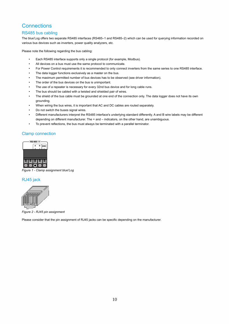
Clamp connection
Figure 1 - Clamp assignment blue'Log
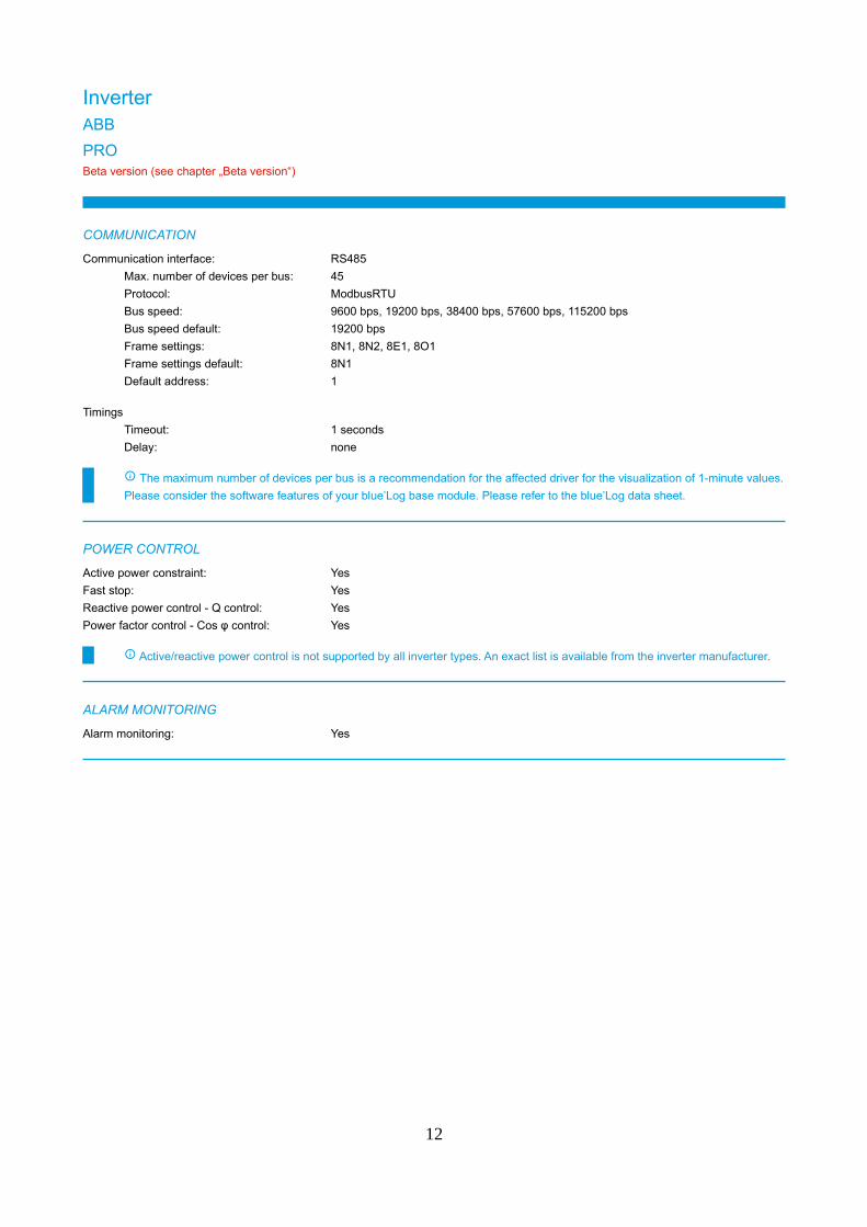
RJ45 jack
Figure 2 - RJ45 pin assignment
Please consider that the pin assignment of RJ45 jacks can be specific depending on the manufacturer.
10

Max. number of devices Value for max. number of devices in COMMUNICATION section of each driver got calculated theoretically
These values got calculated based on the requirements, Power Control and Monitoring without data gaps
Please check the manufacturer documentation for information regarding the maximum amount of devices which can be
connected to one RS485 bus or to a communication gateway
Beta versionPlease note: Drivers which are tagged with Beta-Version
have not been tested in the field yet
are just available via meteocontrol support
If beta version tagged driver should be required, please contact meteocontrol support:
Technical support:
Phone: +49 (0)821 34666 - 44
E-mail: [email protected]
11
InverterABB
PROBeta version (see chapter „Beta version“)
COMMUNICATION
Communication interface: RS485
Max. number of devices per bus: 45
Protocol: ModbusRTU
Bus speed: 9600 bps, 19200 bps, 38400 bps, 57600 bps, 115200 bps
Bus speed default: 19200 bps
Frame settings: 8N1, 8N2, 8E1, 8O1
Frame settings default: 8N1
Default address: 1
Timings
Timeout: 1 seconds
Delay: none
The maximum number of devices per bus is a recommendation for the affected driver for the visualization of 1-minute values.
Please consider the software features of your blue’Log base module. Please refer to the blue’Log data sheet.
POWER CONTROL
Active power constraint: Yes
Fast stop: Yes
Reactive power control - Q control: Yes
Power factor control - Cos φ control: Yes
Active/reactive power control is not supported by all inverter types. An exact list is available from the inverter manufacturer.
ALARM MONITORING
Alarm monitoring: Yes
12
MEASUREMENT VALUES RECORDED
COS_PHI Power factor (cos phi)
ERROR (1,...x) Error (1,...x)
E_TOTAL Energy total
F_AC Grid frequency
I_AC Current AC
I_DC Current DC total
I_DCX_Y Current DC (1,...x).(1,...x)
P_AC Power AC
STATE (1,...x) Status (1,...x)
S_AC Apparent power
U_AC Voltage AC
U_AC1 Voltage AC phase 1
U_AC2 Voltage AC phase 2
U_AC3 Voltage AC phase 3
U_AC_L1L2 Phase voltage L1L2
U_AC_L2L3 Phase voltage L2L3
U_AC_L3L1 Phase voltage L3L1
U_DC Voltage DC
The actually recorded values may vary due to the device model or the device firmware.
SUPPORTED DEVICES
PRO series
PRO-33.0-TL PRO-33.0-TL-OUTD PRO-33.0-TL-OUTD-S-400
PRO-33.0-TL-OUTD-SX-400
Please contact Sales for details of compatibility with devices not listed.
Phone: +49 (0)821 34666 - 80
E-mail: [email protected]
13
PVS 800
COMMUNICATION
Communication interface: Ethernet
Max. number of devices: 100
Protocol: ModbusTCP
Port: 502
Default address: 1
Communication interface: RS485
Max. number of devices per bus: 37
Protocol: ModbusRTU
Bus speed: 600 bps, 1200 bps, 2400 bps, 4800 bps, 9600 bps, 19200 bps
Bus speed default: 9600 bps
Frame settings: 8N1, 8N2, 8E1, 8O1
Frame settings default: 8N1
Default address: 1
Timings
Timeout: 1 seconds
Delay: none
The maximum number of devices per bus is a recommendation for the affected driver for the visualization of 1-minute values.
Please consider the software features of your blue’Log base module. Please refer to the blue’Log data sheet.
POWER CONTROL
Active power constraint: Yes
Fast stop: No
Reactive power control - Q control: Yes
Power factor control - Cos φ control: Yes
Active/reactive power control is not supported by all inverter types. An exact list is available from the inverter manufacturer.
ALARM MONITORING
Alarm monitoring: Yes
14
MEASUREMENT VALUES RECORDED
COS_PHI Power factor (cos phi)
ERROR (1,...x) Error (1,...x)
E_TOTAL Energy total
F_AC Grid frequency
I_AC1 Current AC phase 1
I_AC2 Current AC phase 2
I_AC3 Current AC phase 3
I_DC Current DC total
I_DCX_Y Current DC (1,...x).(1,...x)
OT_AC_TOTAL Total operating hours
P_AC Power AC
P_DC Power DC
Q_AC Reactive power
R_ISO Insulation resistance
STATE (1,...x) Status (1,...x)
T (1,...x) Temperature (1,...x)
U_AC1 Voltage AC phase 1
U_AC2 Voltage AC phase 2
U_AC3 Voltage AC phase 3
U_DC Voltage DC
The actually recorded values may vary due to the device model or the device firmware.
15

PVS 800-57B
COMMUNICATION
Communication interface: Ethernet
Max. number of devices: 100
Protocol: ModbusTCP
Port: 502
Default address: 1
Communication interface: RS485
Max. number of devices per bus: 22
Protocol: ModbusRTU
Bus speed: 9600 bps, 19200 bps, 38400 bps, 57600 bps, 115200 bps
Bus speed default: 9600 bps
Frame settings: 8N1, 8N2, 8E1, 8O1
Frame settings default: 8N1
Default address: 1
Timings
Timeout: 1 seconds
Delay: none
The maximum number of devices per bus is a recommendation for the affected driver for the visualization of 1-minute values.
Please consider the software features of your blue’Log base module. Please refer to the blue’Log data sheet.
POWER CONTROL
Active power constraint: Yes
Fast stop: Yes
Reactive power control - Q control: Yes
Power factor control - Cos φ control: Yes
Active/reactive power control is not supported by all inverter types. An exact list is available from the inverter manufacturer.
ALARM MONITORING
Alarm monitoring: Yes
16
MEASUREMENT VALUES RECORDED
COS_PHI Power factor (cos phi)
ERROR (1,...x) Error (1,...x)
E_DAY Energy generated per day
E_TOTAL Energy total
F_AC Grid frequency
I_AC Current AC
I_DC Current DC total
I_DCX_Y Current DC (1,...x).(1,...x)
P_AC Power AC
Q_AC Reactive power
R_ISO Insulation resistance
S_AC Apparent power
T (1,...x) Temperature (1,...x)
U_AC Voltage AC
U_AC1 Voltage AC phase 1
U_AC2 Voltage AC phase 2
U_AC3 Voltage AC phase 3
U_AC_L1L2 Phase voltage L1L2
U_AC_L2L3 Phase voltage L2L3
U_AC_L3L1 Phase voltage L3L1
U_DC Voltage DC
The actually recorded values may vary due to the device model or the device firmware.
SUPPORTED DEVICES
PVS 800-57B
For connection of PVS800-57B only inverters with firmware (DTC) version ≥ 1.41 get supported.
Please contact Sales for details of compatibility with devices not listed.
Phone: +49 (0)821 34666 - 80
E-mail: [email protected]
17

PVS 980
COMMUNICATION
Communication interface: Ethernet
Max. number of devices: 100
Protocol: ModbusTCP
Port: 502
Default address: 1
Communication interface: RS485
Max. number of devices per bus: 22
Protocol: ModbusRTU
Bus speed: 9600 bps, 19200 bps, 38400 bps, 57600 bps, 115200 bps
Bus speed default: 9600 bps
Frame settings: 8N1, 8N2, 8E1, 8O1
Frame settings default: 8N1
Default address: 1
Timings
Timeout: 1 seconds
Delay: none
The maximum number of devices per bus is a recommendation for the affected driver for the visualization of 1-minute values.
Please consider the software features of your blue’Log base module. Please refer to the blue’Log data sheet.
POWER CONTROL
Active power constraint: Yes
Fast stop: Yes
Reactive power control - Q control: Yes
Power factor control - Cos φ control: Yes
Active/reactive power control is not supported by all inverter types. An exact list is available from the inverter manufacturer.
ALARM MONITORING
Alarm monitoring: Yes
18
MEASUREMENT VALUES RECORDED
COS_PHI Power factor (cos phi)
ERROR (1,...x) Error (1,...x)
E_DAY Energy generated per day
E_TOTAL Energy total
F_AC Grid frequency
I_AC Current AC
I_DC Current DC total
I_DCX_Y Current DC (1,...x).(1,...x)
P_AC Power AC
Q_AC Reactive power
R_ISO Insulation resistance
S_AC Apparent power
T (1,...x) Temperature (1,...x)
U_AC Voltage AC
U_AC1 Voltage AC phase 1
U_AC2 Voltage AC phase 2
U_AC3 Voltage AC phase 3
U_AC_L1L2 Phase voltage L1L2
U_AC_L2L3 Phase voltage L2L3
U_AC_L3L1 Phase voltage L3L1
U_DC Voltage DC
The actually recorded values may vary due to the device model or the device firmware.
SUPPORTED DEVICES
PVS 980
For connection of PVS980 only inverters with firmware (DTC) version ≥ 1.41 get supported.
Please contact Sales for details of compatibility with devices not listed.
Phone: +49 (0)821 34666 - 80
E-mail: [email protected]
19
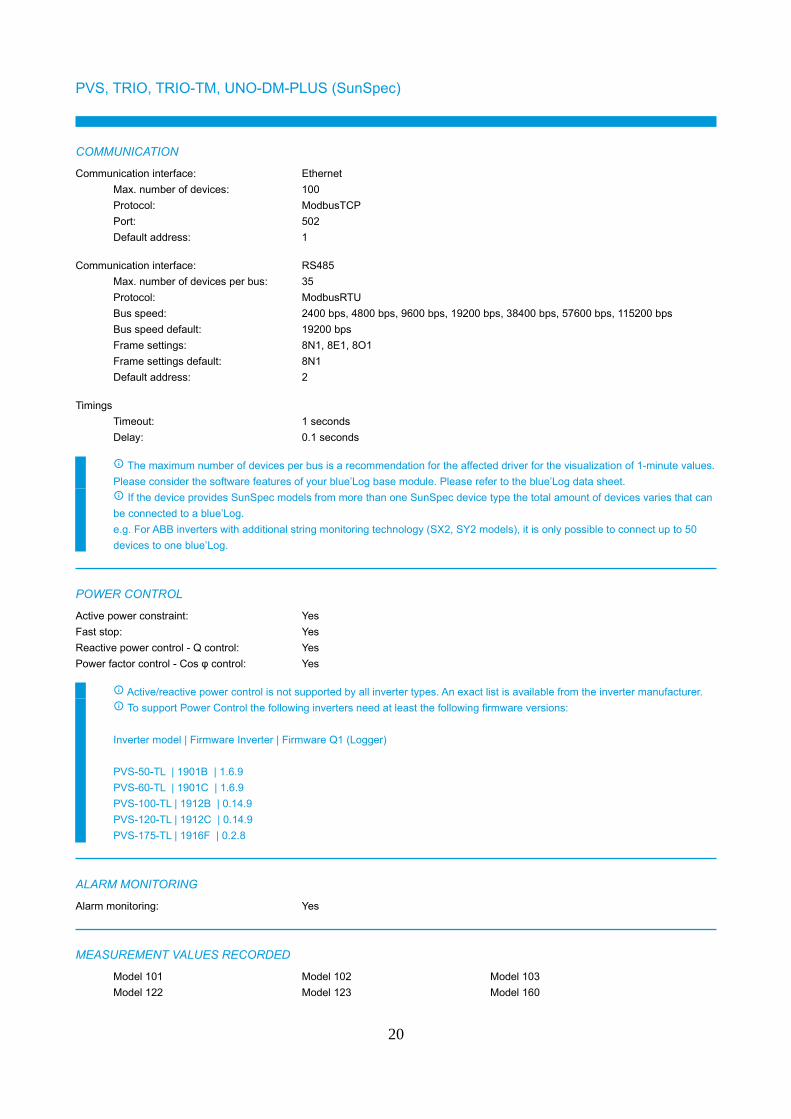
PVS, TRIO, TRIO-TM, UNO-DM-PLUS (SunSpec)
COMMUNICATION
Communication interface: Ethernet
Max. number of devices: 100
Protocol: ModbusTCP
Port: 502
Default address: 1
Communication interface: RS485
Max. number of devices per bus: 35
Protocol: ModbusRTU
Bus speed: 2400 bps, 4800 bps, 9600 bps, 19200 bps, 38400 bps, 57600 bps, 115200 bps
Bus speed default: 19200 bps
Frame settings: 8N1, 8E1, 8O1
Frame settings default: 8N1
Default address: 2
Timings
Timeout: 1 seconds
Delay: 0.1 seconds
The maximum number of devices per bus is a recommendation for the affected driver for the visualization of 1-minute values.
Please consider the software features of your blue’Log base module. Please refer to the blue’Log data sheet.
If the device provides SunSpec models from more than one SunSpec device type the total amount of devices varies that can
be connected to a blue’Log.
e.g. For ABB inverters with additional string monitoring technology (SX2, SY2 models), it is only possible to connect up to 50
devices to one blue’Log.
POWER CONTROL
Active power constraint: Yes
Fast stop: Yes
Reactive power control - Q control: Yes
Power factor control - Cos φ control: Yes
Active/reactive power control is not supported by all inverter types. An exact list is available from the inverter manufacturer.
To support Power Control the following inverters need at least the following firmware versions:
Inverter model | Firmware Inverter | Firmware Q1 (Logger)
PVS-50-TL | 1901B | 1.6.9
PVS-60-TL | 1901C | 1.6.9
PVS-100-TL | 1912B | 0.14.9
PVS-120-TL | 1912C | 0.14.9
PVS-175-TL | 1916F | 0.2.8
ALARM MONITORING
Alarm monitoring: Yes
MEASUREMENT VALUES RECORDED
Model 101 Model 102 Model 103
Model 122 Model 123 Model 160
20
The actually recorded values may vary due to the device model or the device firmware.
For ABB inverters with additional string monitoring technology (SX2, SY2 models) the SunSpec String Combiner Model 403
is also supported.
SUPPORTED DEVICES
PVS series
PVS-50-TL PVS-60-TL PVS-60-TL-CN
PVS-60-TL-US PVS-100.0-400-EU PVS-120.0-480-EU
PVS-175.0-800-EU PVS-175.0-800-EU_A.1
TRIO series
TRIO-50.0-TL-OUTD TRIO-50.0-TL-OUTD-JP TRIO-50.0-TL-OUTD-US
TRIO-60.0-TL-OUTD TRIO-60.0-TL-OUTD-US
TRIO-TM series
TRIO-TM-50.0-400 TRIO-TM-60.0-480 TRIO-TM-60.0-480-US
UNO-DM-PLUS series
UNO-DM-1.2-TL-PLUS UNO-DM-2.0-TL-PLUS UNO-DM-3.3-TL-PLUS-US
UNO-DM-3.8-TL-PLUS UNO-DM-3.8-TL-PLUS-US UNO-DM-4.0-TL-PLUS
UNO-DM-4.6-TL-PLUS UNO-DM-5.0-TL-PLUS UNO-DM-5.0-TL-PLUS-US
UNO-DM-6.0-TL-PLUS UNO-DM-6.0-TL-PLUS-US
Please contact Sales for details of compatibility with devices not listed.
Phone: +49 (0)821 34666 - 80
E-mail: [email protected]
21
TRIO-20.0/27.6-TL-OUTD
COMMUNICATION
Communication interface: RS485
Max. number of devices per bus: 58
Protocol: ModbusRTU
Bus speed: 2400 bps, 4800 bps, 9600 bps, 19200 bps, 38400 bps, 57600 bps, 115200 bps
Bus speed default: 19200 bps
Frame settings: 8N1
Frame settings default: 8N1
Default address: 1
Timings
Timeout: 1 seconds
Delay: 0.05 seconds
The maximum number of devices per bus is a recommendation for the affected driver for the visualization of 1-minute values.
Please consider the software features of your blue’Log base module. Please refer to the blue’Log data sheet.
POWER CONTROL
Active power constraint: Yes
Fast stop: Yes
Reactive power control - Q control: Yes
Power factor control - Cos φ control: Yes
Active/reactive power control is not supported by all inverter types. An exact list is available from the inverter manufacturer.
"Fast stop" is only being supported in case the “Remote on/off” function is enabled in the inverter.
ALARM MONITORING
Alarm monitoring: Yes
MEASUREMENT VALUES RECORDED
COS_PHI Power factor (cos phi)
ERROR (1,...x) Error (1,...x)
E_DAY Energy generated per day
E_TOTAL Energy total
F_AC Grid frequency
I_AC Current AC
I_DC (1,...x) Current DC string (1,...x)
I_DCX_Y Current DC (1,...x).(1,...x)
P_AC Power AC
P_DC (1,...x) Power DC string (1,...x)
R_ISO Insulation resistance
STATE (1,...x) Status (1,...x)
T (1,...x) Temperature (1,...x)
U_AC Voltage AC
U_DC (1,...x) Voltage DC string (1,...x)
The actually recorded values may vary due to the device model or the device firmware.
22

SUPPORTED DEVICES
TRIO series
TRIO-20-TL-OUTD-400 TRIO-20-TL-OUTD-480 TRIO-27.6-TL-OUTD-400
TRIO-27.6-TL-OUTD-480
Please contact Sales for details of compatibility with devices not listed.
Phone: +49 (0)821 34666 - 80
E-mail: [email protected]
23
ULTRA 750/1100/1500Beta version (see chapter „Beta version“)
COMMUNICATION
Communication interface: RS485
Max. number of devices per bus: 100
Protocol: ModbusRTU
Bus speed: 19200 bps
Bus speed default: 19200 bps
Frame settings: 8N1
Frame settings default: 8N1
Default address: 3
Timings
Timeout: 5 seconds
Delay: none
The maximum number of devices per bus is a recommendation for the affected driver for the visualization of 1-minute values.
Please consider the software features of your blue’Log base module. Please refer to the blue’Log data sheet.
POWER CONTROL
Active power constraint: Yes
Fast stop: Yes
Reactive power control - Q control: Yes
Power factor control - Cos φ control: Yes
Active/reactive power control is not supported by all inverter types. An exact list is available from the inverter manufacturer.
ALARM MONITORING
Alarm monitoring: Yes
MEASUREMENT VALUES RECORDED
E_DAY Energy generated per day
E_TOTAL Energy total
F_AC Grid frequency
I_AC Current AC
I_AC1 Current AC phase 1
I_AC2 Current AC phase 2
I_AC3 Current AC phase 3
I_DC Current DC total
P_AC Power AC
P_DC Power DC
Q_AC Reactive power
STATE (1,...x) Status (1,...x)
T (1,...x) Temperature (1,...x)
U_AC Voltage AC
U_AC1 Voltage AC phase 1
U_AC2 Voltage AC phase 2
U_AC3 Voltage AC phase 3
U_DC Voltage DC
24

The actually recorded values may vary due to the device model or the device firmware.
SUPPORTED DEVICES
ULTRA series
ULTRA 750 ULTRA 1100 ULTRA 1500
Please contact Sales for details of compatibility with devices not listed.
Phone: +49 (0)821 34666 - 80
E-mail: [email protected]
25
UNO, TRIO, PVI, PVI-CENTRAL, REACT, ULTRA, PLUS, CORE (Aurora Protocol)
COMMUNICATION
Communication interface: RS485
Max. number of devices per bus: 31
Protocol: AURORA
Bus speed: 2400 bps, 4800 bps, 9600 bps, 19200 bps
Bus speed default: 19200 bps
Frame settings: 8N1
Frame settings default: 8N1
Default address: 2
Timings
Timeout: 0.5 seconds
Delay: 0.035 seconds
The maximum number of devices per bus is a recommendation for the affected driver for the visualization of 1-minute values.
Please consider the software features of your blue’Log base module. Please refer to the blue’Log data sheet.
In case String Boxes from ABB should be connected to inverters of the series Plus, Central, Core, Ultra the blue’Log would
automatically create a string combiner device for every device connected during the inverter scan.
Depending on the amount of ABB string boxes connected to each inverter the total amount of devices varies that can be
connected to one blue’Log.
The maximum number of ABB string boxes which can be connected are:
- Ultra series: 80
- Plus / Central / Core series: 12
POWER CONTROL
Active power constraint: Yes
Fast stop: No
Reactive power control - Q control: Yes
Power factor control - Cos φ control: Yes
Active/reactive power control is not supported by all inverter types. An exact list is available from the inverter manufacturer.
Power Control is only possible in OPEN-LOOP mode. In CLOSED-LOOP inverter communication is too slow for "Monitoring"
and "Power Control".
ALARM MONITORING
Alarm monitoring: Yes
26
MEASUREMENT VALUES RECORDED
COS_PHI Power factor (cos phi)
ERROR (1,...x) Error (1,...x)
E_DAY Energy generated per day
E_TOTAL Energy total
F_AC Grid frequency
F_AC1 Grid frequency phase 1
F_AC2 Grid frequency phase 2
F_AC3 Grid frequency phase 3
I_AC Current AC
I_AC1 Current AC phase 1
I_AC2 Current AC phase 2
I_AC3 Current AC phase 3
I_DC Current DC total
I_DC (1,...x) Current DC string (1,...x)
I_DCX_Y Current DC (1,...x).(1,...x)
OT_AC_TOTAL Total operating hours
P_AC Power AC
P_DC Power DC
P_DC (1,...x) Power DC string (1,...x)
Q_AC Reactive power
R_ISO Insulation resistance
STATE (1,...x) Status (1,...x)
T (1,...x) Temperature (1,...x)
U_AC Voltage AC
U_AC1 Voltage AC phase 1
U_AC2 Voltage AC phase 2
U_AC3 Voltage AC phase 3
U_DC Voltage DC
U_DC (1,...x) Voltage DC string (1,...x)
The actually recorded values may vary due to the device model or the device firmware.
SUPPORTED DEVICES
Central series
PVI-CENTRAL-50/55 module PVI-CENTRAL-67 module PVI-CENTRAL-250
PVI-CENTRAL-CORE (control board) SYSTEM CONTROLLER
27
String Inverter series
3-phase interface (3G74) 11.0 KVA Universal (output 400 VAC) 13.8 KVA Universal (output 400 VAC)
CDD PVI-3.0-OUTD PVI-3.6-OUTD
PVI-3.8-I-OUTD PVI-3.8-OUTD PVI-4.2-OUTD
PVI-4.6-I-OUTD PVI-6.0-OUTD Universal (output 400 VAC) PVI-6.0-TL-OUTD
PVI-8.0-OUTD Universal PVI-8.0-OUTD Universal PLUS PVI-8.0-TL-OUTD
PVI-10.0-I-OUTD (output 208 VAC) PVI-10.0-I-OUTD (output 380 VAC) PVI-10.0-I-OUTD (output 480 VAC – current
limit 12 A)
PVI-10.0-I-OUTD (output 480 VAC) PVI-10.0-I-OUTD (output 600 VAC) PVI-10.0-OUTD
PVI-10.0-OUTD Universal PVI-10.0-TL-OUTD PVI-12.0-I-OUTD (output 208 VAC)
PVI-12.0-I-OUTD (output 380 VAC) PVI-12.0-I-OUTD (output 480 VAC) PVI-12.0-I-OUTD (output 600 VAC)
PVI-12.5-OUTD PVI-12.5-OUTD Universal PVI-12.5-TL-OUTD
PVI-1700-IND PVI-1700-OUTD PVI-2000
PVI-2000-OUTD PVI-3600 PVI-3600-OUTD
PVI-5000-OUTD PVI-6000-OUTD REACT
TRIO-5.0-TL-OUTD TRIO-5.8-OUTD (output 400 VAC) TRIO-7.5-OUTD (output 400 VAC)
TRIO-8.5-OUTD (output 400 VAC) TRIO-20-TL TRIO-20.0 (output 480 VAC)
TRIO-25.0-OUTD TRIO-27.6 (output 480 VAC) TRIO-27.6-TL
TRIO-50.0-TL-OUTD TRIO-50.0-TL-OUTD-JP TRIO-50.0-TL-US
TRIO-60.0-TL-OUTD TRIO-60.0-TL-OUTD-US TRIO-TM-50.0-400 / TRIO-TM-60.0-480
UNO-2.0-I UNO-2.0-TL-OUTD UNO-2.0-TL-OUTD-US
UNO-2.5-I UNO-3.0-TL-OUTD UNO-3.0-TL-OUTD-US
UNO-3.6-TL-OUTD UNO-3.8-TL-OUTD UNO-4.2-TL-OUTD
UNO-7.6-TL-OUTD UNO-8.6-TL-OUTD
Ultra series
PVI-CENTRAL-350 Liquid Cooled (AC gathering) PVI-CENTRAL-350 Liquid Cooled (control
board) PVI-CENTRAL-350 Liquid Cooled (display board)
Please contact Sales for details of compatibility with devices not listed.
Phone: +49 (0)821 34666 - 80
E-mail: [email protected]
28

Advanced Energy
PVPXXXX_PVP30KW/AExxxTXBeta version (see chapter „Beta version“)
COMMUNICATION
Communication interface: Ethernet
Max. number of devices: 100
Protocol: ModbusTCP
Port: 502
Default address: 1
Communication interface: RS485
Max. number of devices per bus: 83
Protocol: ModbusRTU
Bus speed: 9600 bps, 19200 bps, 38400 bps, 57600 bps
Bus speed default: 9600 bps
Frame settings: 8N1
Frame settings default: 8N1
Default address: 1
Timings
Timeout: 1 seconds
Delay: 0.01 seconds
The maximum number of devices per bus is a recommendation for the affected driver for the visualization of 1-minute values.
Please consider the software features of your blue’Log base module. Please refer to the blue’Log data sheet.
POWER CONTROL
Active power constraint: No
Fast stop: No
Reactive power control - Q control: No
Power factor control - Cos φ control: No
Active/reactive power control is not supported by all inverter types. An exact list is available from the inverter manufacturer.
ALARM MONITORING
Alarm monitoring: Yes
29
MEASUREMENT VALUES RECORDED
ERROR (1,...x) Error (1,...x)
E_TOTAL Energy total
F_AC Grid frequency
I_AC Current AC
I_AC1 Current AC phase 1
I_AC2 Current AC phase 2
I_AC3 Current AC phase 3
I_DC Current DC total
P_AC Power AC
P_DC Power DC
STATE (1,...x) Status (1,...x)
U_AC1 Voltage AC phase 1
U_AC2 Voltage AC phase 2
U_AC3 Voltage AC phase 3
U_AC_L1L2 Phase voltage L1L2
U_DC Voltage DC
The actually recorded values may vary due to the device model or the device firmware.
SUPPORTED DEVICES
PVP30/AExxxTX series
AE35TX AE50TX AE75TX
AE100TX AE250TX/AE260TX AE500TX
PVP30KW
PVPxxxx series
PVP4600
Please contact Sales for details of compatibility with devices not listed.
Phone: +49 (0)821 34666 - 80
E-mail: [email protected]
30
AROS (Riello)
SIRIO K12 - K800 central inverter
COMMUNICATION
Communication interface: Ethernet
Max. number of devices: 100
Protocol: ModbusTCP
Port: 502
Default address: 1
Communication interface: RS485
Max. number of devices per bus: 49
Protocol: ModbusRTU
Bus speed: 9600 bps
Bus speed default: 9600 bps
Frame settings: 8N1
Frame settings default: 8N1
Default address: 1
Timings
Timeout: 1 seconds
Delay: none
The maximum number of devices per bus is a recommendation for the affected driver for the visualization of 1-minute values.
Please consider the software features of your blue’Log base module. Please refer to the blue’Log data sheet.
POWER CONTROL
Active power constraint: Yes
Fast stop: Yes
Reactive power control - Q control: Yes
Power factor control - Cos φ control: Yes
Active/reactive power control is not supported by all inverter types. An exact list is available from the inverter manufacturer.
ALARM MONITORING
Alarm monitoring: Yes
31
MEASUREMENT VALUES RECORDED
ERROR (1,...x) Error (1,...x)
E_TOTAL Energy total
F_AC Grid frequency
I_AC1 Current AC phase 1
I_AC2 Current AC phase 2
I_AC3 Current AC phase 3
I_DC (1,...x) Current DC string (1,...x)
I_DCX_Y Current DC (1,...x).(1,...x)
OT_AC_TOTAL Total operating hours
P_AC1 Power AC phase 1
P_AC2 Power AC phase 2
P_AC3 Power AC phase 3
Q_AC1 Reactive power phase 1
Q_AC2 Reactive power phase 2
Q_AC3 Reactive power phase 3
STATE (1,...x) Status (1,...x)
T Temperature
U_AC1 Voltage AC phase 1
U_AC2 Voltage AC phase 2
U_AC3 Voltage AC phase 3
U_DC (1,...x) Voltage DC string (1,...x)
The actually recorded values may vary due to the device model or the device firmware.
SUPPORTED DEVICES
Sirio Central Inverters series
Sirio K12 Sirio K15 Sirio K18
Sirio K25 Series Sirio K33 Series Sirio K40 Series
Sirio K64 Series Sirio K80 Series Sirio K100 Series
Sirio K200 Series Sirio K250 Series Sirio K330 Series
Sirio K500 Series Sirio K800 Series
Please contact Sales for details of compatibility with devices not listed.
Phone: +49 (0)821 34666 - 80
E-mail: [email protected]
32
Chint
CPS SeriesBeta version (see chapter „Beta version“)
COMMUNICATION
Communication interface: Ethernet
Max. number of devices: 100
Protocol: ModbusTCP
Port: 502
Default address: 1
Communication interface: RS485
Max. number of devices per bus: 74
Protocol: ModbusRTU
Bus speed: 2400 bps, 4800 bps, 9600 bps, 19200 bps, 38400 bps
Bus speed default: 9600 bps
Frame settings: 8N1
Frame settings default: 8N1
Default address: 1
Timings
Timeout: 1 seconds
Delay: none
The maximum number of devices per bus is a recommendation for the affected driver for the visualization of 1-minute values.
Please consider the software features of your blue’Log base module. Please refer to the blue’Log data sheet.
POWER CONTROL
Active power constraint: Yes
Fast stop: Yes
Reactive power control - Q control: Yes
Power factor control - Cos φ control: Yes
Active/reactive power control is not supported by all inverter types. An exact list is available from the inverter manufacturer.
ALARM MONITORING
Alarm monitoring: Yes
33

MEASUREMENT VALUES RECORDED
COS_PHI Power factor (cos phi)
ERROR (1,...x) Error (1,...x)
E_DAY Energy generated per day
E_TOTAL Energy total
F_AC Grid frequency
I_AC1 Current AC phase 1
I_AC2 Current AC phase 2
I_AC3 Current AC phase 3
I_DC Current DC total
I_DC (1,...x) Current DC string (1,...x)
I_DCX_Y Current DC (1,...x).(1,...x)
P_AC Power AC
P_DC Power DC
Q_AC Reactive power
STATE (1,...x) Status (1,...x)
S_AC Apparent power
T (1,...x) Temperature (1,...x)
U_AC_L1L2 Phase voltage L1L2
U_AC_L2L3 Phase voltage L2L3
U_AC_L3L1 Phase voltage L3L1
U_DC Voltage DC
U_DC (1,...x) Voltage DC string (1,...x)
The actually recorded values may vary due to the device model or the device firmware.
SUPPORTED DEVICES
CPS series
SCA14KTL-DO/US-208 SCA20KTL-DO SCA25KTL-DO
SCA30KTL-DO SCA36KTL-DO SCA50KTL-DO
SCA60KTL-DO SCA500KTL-H SCA1000KTL-H
SCH1250K SCH1500K
Please contact Sales for details of compatibility with devices not listed.
Phone: +49 (0)821 34666 - 80
E-mail: [email protected]
34
Danfoss
DLX, FLX, TLX, ULX
COMMUNICATION
Communication interface: Ethernet
Max. number of devices: 100
Protocol: DANFOSS_ETHER_LYNX
Port: 48004
Default address: 0
Communication interface: RS485
Max. number of devices per bus: 64
Protocol: DANFOSS_COM_LYNX
Bus speed: 19200 bps
Bus speed default: 19200 bps
Frame settings: 8N1
Frame settings default: 8N1
Default address: 0
Timings
Timeout: 1 seconds
Delay: 0.005 seconds
The maximum number of devices per bus is a recommendation for the affected driver for the visualization of 1-minute values.
Please consider the software features of your blue’Log base module. Please refer to the blue’Log data sheet.
Please note that Danfoss considers RX/TX A ( - ) and RX/TX B ( + ). When connecting Danfoss inverters via RS485 to
blue’Log A and B need to be changed.
TLX Pro supports Ethernet communication.
Scan on RS485 takes several minutes to finish without visible progress in between.
POWER CONTROL
Active power constraint: Yes
Fast stop: No
Reactive power control - Q control: Yes
Power factor control - Cos φ control: Yes
Active/reactive power control is not supported by all inverter types. An exact list is available from the inverter manufacturer.
Only TLX inverter with software version ≥ 1.04 are supporting active Power Control. Only TLX+ inverter support active and
reactive Power Control.
ULX inverter with software version ≥ 1.82 support active and reactive Power Control. With software version > 1.67 and < 1.82
only reactive Power Control is possible.
DLX inverter don't support Power Control.
ALARM MONITORING
Alarm monitoring: Yes
35
MEASUREMENT VALUES RECORDED
ERROR (1,...x) Error (1,...x)
E_DAY Energy generated per day
E_TOTAL Energy total
F_AC Grid frequency
I_AC Current AC
I_AC1 Current AC phase 1
I_AC2 Current AC phase 2
I_AC3 Current AC phase 3
I_DC Current DC total
I_DC (1,...x) Current DC string (1,...x)
P_AC Power AC
P_AC1 Power AC phase 1
P_AC2 Power AC phase 2
P_AC3 Power AC phase 3
P_DC Power DC
P_DC (1,...x) Power DC string (1,...x)
STATE (1,...x) Status (1,...x)
U_AC Voltage AC
U_AC1 Voltage AC phase 1
U_AC2 Voltage AC phase 2
U_AC3 Voltage AC phase 3
U_AC_L1L2 Phase voltage L1L2
U_AC_L2L3 Phase voltage L2L3
U_AC_L3L1 Phase voltage L3L1
U_DC Voltage DC
U_DC (1,...x) Voltage DC string (1,...x)
The actually recorded values may vary due to the device model or the device firmware.
SUPPORTED DEVICES
DLX series
DLX 2.0 DLX 2.9 DLX 3.8
DLX 4.6
FLX series
FLX Pro 5 FLX Pro 6 FLX Pro 7
FLX Pro 8 FLX Pro 9 FLX Pro 10
FLX Pro 12.5 FLX Pro 15 FLX Pro 17
TLX series
TLX series 6 k TLX series 8 k TLX series 10 k
TLX series 12.5 k TLX series 15 k
ULX series
ULX 1800 ULX 3600 ULX 5400
Please contact Sales for details of compatibility with devices not listed.
Phone: +49 (0)821 34666 - 80
E-mail: [email protected]
36
Delta
M (Q@night, only Q method) (SunSpec)
COMMUNICATION
Communication interface: RS485
Max. number of devices per bus: 72
Protocol: ModbusRTU
Bus speed: 9600 bps, 19200 bps, 38400 bps
Bus speed default: 19200 bps
Frame settings: 8N1
Frame settings default: 8N1
Default address: 1
Timings
Timeout: 2 seconds
Delay: none
The maximum number of devices per bus is a recommendation for the affected driver for the visualization of 1-minute values.
Please consider the software features of your blue’Log base module. Please refer to the blue’Log data sheet.
For communication via SunSpec the inverters must be configured accordingly. (please see inverter manufacturer
documentation for more information).
If the device provides SunSpec models from more than one SunSpec device type the total amount of devices varies that can
be connected to a blue’Log.
e.g. For Delta inverters with additional string monitoring technology (e.g. Delta M88H), it is only possible to connect up to 50
devices to one blue’Log.
POWER CONTROL
Active power constraint: Yes
Fast stop: Yes
Reactive power control - Q control: Yes
Power factor control - Cos φ control: No
Active/reactive power control is not supported by all inverter types. An exact list is available from the inverter manufacturer.
ALARM MONITORING
Alarm monitoring: Yes
MEASUREMENT VALUES RECORDED
Model 101 Model 102 Model 103
Model 122 Model 123 Model 160
The actually recorded values may vary due to the device model or the device firmware.
SUPPORTED DEVICES
M15A M20A M30A
M42U M50A M60U
M80U M88H M125HV
37

Please contact Sales for details of compatibility with devices not listed.
Phone: +49 (0)821 34666 - 80
E-mail: [email protected]
38
M (SunSpec)
COMMUNICATION
Communication interface: RS485
Max. number of devices per bus: 72
Protocol: ModbusRTU
Bus speed: 9600 bps, 19200 bps, 38400 bps
Bus speed default: 19200 bps
Frame settings: 8N1
Frame settings default: 8N1
Default address: 1
Timings
Timeout: 2 seconds
Delay: none
The maximum number of devices per bus is a recommendation for the affected driver for the visualization of 1-minute values.
Please consider the software features of your blue’Log base module. Please refer to the blue’Log data sheet.
For communication via SunSpec the inverters must be configured accordingly. (please see inverter manufacturer
documentation for more information).
If the device provides SunSpec models from more than one SunSpec device type the total amount of devices varies that can
be connected to a blue’Log.
e.g. For Delta inverters with additional string monitoring technology (e.g. Delta M88H), it is only possible to connect up to 50
devices to one blue’Log.
POWER CONTROL
Active power constraint: Yes
Fast stop: Yes
Reactive power control - Q control: Yes
Power factor control - Cos φ control: Yes
Active/reactive power control is not supported by all inverter types. An exact list is available from the inverter manufacturer.
ALARM MONITORING
Alarm monitoring: Yes
MEASUREMENT VALUES RECORDED
Model 101 Model 102 Model 103
Model 122 Model 123 Model 160
The actually recorded values may vary due to the device model or the device firmware.
SUPPORTED DEVICES
M15A M20A M30A
M42U M50A M60U
M80U M88H M125HV
39

Please contact Sales for details of compatibility with devices not listed.
Phone: +49 (0)821 34666 - 80
E-mail: [email protected]
40
EEI
8YF
COMMUNICATION
Communication interface: Ethernet
Max. number of devices: 100
Protocol: ModbusTCP
Port: 502
Default address: 1
Timings
Timeout: 1 seconds
Delay: none
The maximum number of devices per bus is a recommendation for the affected driver for the visualization of 1-minute values.
Please consider the software features of your blue’Log base module. Please refer to the blue’Log data sheet.
POWER CONTROL
Active power constraint: No
Fast stop: No
Reactive power control - Q control: No
Power factor control - Cos φ control: No
Active/reactive power control is not supported by all inverter types. An exact list is available from the inverter manufacturer.
ALARM MONITORING
Alarm monitoring: Yes
MEASUREMENT VALUES RECORDED
ERROR (1,...x) Error (1,...x)
F_AC Grid frequency
I_AC1 Current AC phase 1
I_AC2 Current AC phase 2
I_AC3 Current AC phase 3
I_DC (1,...x) Current DC string (1,...x)
P_AC Power AC
P_DC Power DC
P_DC (1,...x) Power DC string (1,...x)
Q_AC Reactive power
STATE (1,...x) Status (1,...x)
T (1,...x) Temperature (1,...x)
U_AC Voltage AC
U_DC Voltage DC
U_DC (1,...x) Voltage DC string (1,...x)
The actually recorded values may vary due to the device model or the device firmware.
41
FIMER
R400 - R5000TLBeta version (see chapter „Beta version“)
COMMUNICATION
Communication interface: RS485
Max. number of devices per bus: 65
Protocol: ModbusRTU
Bus speed: 1200 bps, 2400 bps, 4800 bps, 9600 bps, 19200 bps, 38400 bps, 57600 bps,
115200 bps
Bus speed default: 9600 bps
Frame settings: 8N1, 8E1, 8O1
Frame settings default: 8E1
Default address: 1
Timings
Timeout: 1 seconds
Delay: none
The maximum number of devices per bus is a recommendation for the affected driver for the visualization of 1-minute values.
Please consider the software features of your blue’Log base module. Please refer to the blue’Log data sheet.
POWER CONTROL
Active power constraint: No
Fast stop: No
Reactive power control - Q control: No
Power factor control - Cos φ control: No
Active/reactive power control is not supported by all inverter types. An exact list is available from the inverter manufacturer.
ALARM MONITORING
Alarm monitoring: Yes
42
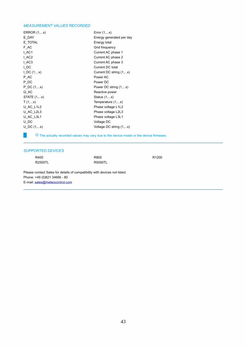
MEASUREMENT VALUES RECORDED
ERROR (1,...x) Error (1,...x)
E_DAY Energy generated per day
E_TOTAL Energy total
F_AC Grid frequency
I_AC1 Current AC phase 1
I_AC2 Current AC phase 2
I_AC3 Current AC phase 3
I_DC Current DC total
I_DC (1,...x) Current DC string (1,...x)
P_AC Power AC
P_DC Power DC
P_DC (1,...x) Power DC string (1,...x)
Q_AC Reactive power
STATE (1,...x) Status (1,...x)
T (1,...x) Temperature (1,...x)
U_AC_L1L2 Phase voltage L1L2
U_AC_L2L3 Phase voltage L2L3
U_AC_L3L1 Phase voltage L3L1
U_DC Voltage DC
U_DC (1,...x) Voltage DC string (1,...x)
The actually recorded values may vary due to the device model or the device firmware.
SUPPORTED DEVICES
R400 R800 R1200
R2500TL R5000TL
Please contact Sales for details of compatibility with devices not listed.
Phone: +49 (0)821 34666 - 80
E-mail: [email protected]
43

FRIEM
RECon 30 Central Inverter (firmware > 2.42.0)
COMMUNICATION
Communication interface: RS485
Max. number of devices per bus: 100
Protocol: ModbusRTU
Bus speed: 9600 bps, 19200 bps, 38400 bps, 115200 bps
Bus speed default: 38400 bps
Frame settings: 8N1
Frame settings default: 8N1
Default address: 1
Timings
Timeout: 2 seconds
Delay: none
The maximum number of devices per bus is a recommendation for the affected driver for the visualization of 1-minute values.
Please consider the software features of your blue’Log base module. Please refer to the blue’Log data sheet.
FRIEM RECon central inverters consist of several inverter modules (up to 6) and string combiners (up to 18).
Depending on the combination of modules and string combiners the total amount of devices varies that can be connected to one
blue’Log (e.g. 1 FRIEM RECon central inverter with 6 inverter modules + 18 string combiner = 24 devices).
Please note for connection of FRIEM RECon inverters with only a RS232 interface an additional RS232/RS485 converter is
required for connection via Modbus RTU.
Please note for FRIEM RECon inverters with firmware version up to 2.42.0 the communication via Modbus TCP can't get
used for monitoring.
POWER CONTROL
Active power constraint: No
Fast stop: No
Reactive power control - Q control: No
Power factor control - Cos φ control: No
Active/reactive power control is not supported by all inverter types. An exact list is available from the inverter manufacturer.
ALARM MONITORING
Alarm monitoring: No
MEASUREMENT VALUES RECORDED
The actually recorded values may vary due to the device model or the device firmware.
44

RECon Central Inverter (firmware > 5.4.xx)
COMMUNICATION
Communication interface: Ethernet
Max. number of devices: 100
Protocol: ModbusTCP
Port: 8000
Default address: 1
Communication interface: RS485
Max. number of devices per bus: 100
Protocol: ModbusRTU
Bus speed: 38400 bps
Bus speed default: 38400 bps
Frame settings: 8N1
Frame settings default: 8N1
Default address: 1
Timings
Timeout: 1 seconds
Delay: none
The maximum number of devices per bus is a recommendation for the affected driver for the visualization of 1-minute values.
Please consider the software features of your blue’Log base module. Please refer to the blue’Log data sheet.
FRIEM RECon central inverters with firmware 5.4.xx get supported.
FRIEM RECon central inverters consist of several inverter modules (up to 6) and string combiners (up to 18).
Depending on the combination of modules and string combiners the total amount of devices varies that can be connected to one
blue’Log (e.g. 1 FRIEM RECon central inverter with 6 inverter modules + 18 string combiner = 24 devices).
POWER CONTROL
Active power constraint: No
Fast stop: No
Reactive power control - Q control: No
Power factor control - Cos φ control: No
Active/reactive power control is not supported by all inverter types. An exact list is available from the inverter manufacturer.
ALARM MONITORING
Alarm monitoring: Yes
MEASUREMENT VALUES RECORDED
ERROR (1,...x) Error (1,...x)
F_AC Grid frequency
I (1,...x) Current DC (1,...x)
I_AC Current AC
I_DC (1,...x) Current DC string (1,...x)
I_SUM Sum of DC currents
P_AC Power AC
Q_AC Reactive power
U_AC Voltage AC
U_DC (1,...x) Voltage DC string (1,...x)
45

The actually recorded values may vary due to the device model or the device firmware.
SUPPORTED DEVICES
RECon series
FRIEM stringboxes RECon Centralized Inverters
Please contact Sales for details of compatibility with devices not listed.
Phone: +49 (0)821 34666 - 80
E-mail: [email protected]
46
Fronius
Datamanager 2.0
COMMUNICATION
Communication interface: Ethernet
Max. number of devices: 100
Protocol: ModbusTCP
Port: 502
Default address: 1
Communication interface: RS485
Max. number of devices per bus: 51
Protocol: ModbusRTU
Bus speed: 9600 bps, 19200 bps
Bus speed default: 9600 bps
Frame settings: 8N1, 8E1, 8O1
Frame settings default: 8N1
Default address: 1
Timings
Timeout: 1 seconds
Delay: none
The maximum number of devices per bus is a recommendation for the affected driver for the visualization of 1-minute values.
Please consider the software features of your blue’Log base module. Please refer to the blue’Log data sheet.
Communication via Modbus must be activated on the Fronius Datamanager 2.0 first.
On the Fronius Datamanager 2.0 the Sunspec Model type "int + SF" needs to be selected.
POWER CONTROL
Active power constraint: Yes
Fast stop: Yes
Reactive power control - Q control: Yes
Power factor control - Cos φ control: Yes
Active/reactive power control is not supported by all inverter types. An exact list is available from the inverter manufacturer.
In case of Power Control requirements "Inverter control via Modbus" needs to be activated on the Fronius Datamanager 2.0.
ALARM MONITORING
Alarm monitoring: Yes
MEASUREMENT VALUES RECORDED
Model 101 Model 102 Model 103
Model 122 Model 123 Model 160
The actually recorded values may vary due to the device model or the device firmware.
47

SUPPORTED DEVICES
Datamanager 2.0 plug-in card with Fronius Com Card function series
Fronius CL Fronius CL USA Fronius IG
Fronius IG 300 - 500 Fronius IG Plus Fronius IG Plus A
Fronius IG Plus V
Datamanager 2.0 plug-in card without Fronius Com Card function series
Fronius Eco Fronius Galvo Fronius Primo
Fronius Symo
Datamanager Box 2.0 series
Fronius Agilo Fronius Agilo Outdoor Fronius Agilo TL
Fronius CL Fronius CL USA Fronius Eco
Fronius Galvo Fronius IG Fronius IG 300 - 500
Fronius IG Plus Fronius IG Plus A Fronius IG Plus V
Fronius Primo Fronius Symo
Please contact Sales for details of compatibility with devices not listed.
Phone: +49 (0)821 34666 - 80
E-mail: [email protected]
48
Gamesa Electric
Inverter III 500kW
COMMUNICATION
Communication interface: Ethernet
Max. number of devices: 100
Protocol: ModbusTCP
Port: 502
Default address: 1
Communication interface: RS485
Max. number of devices per bus: 100
Protocol: ModbusRTU
Bus speed: 9600 bps
Bus speed default: 9600 bps
Frame settings: 8E1
Frame settings default: 8E1
Default address: 1
Timings
Timeout: 1 seconds
Delay: none
The maximum number of devices per bus is a recommendation for the affected driver for the visualization of 1-minute values.
Please consider the software features of your blue’Log base module. Please refer to the blue’Log data sheet.
POWER CONTROL
Active power constraint: No
Fast stop: No
Reactive power control - Q control: No
Power factor control - Cos φ control: No
Active/reactive power control is not supported by all inverter types. An exact list is available from the inverter manufacturer.
ALARM MONITORING
Alarm monitoring: Yes
49
MEASUREMENT VALUES RECORDED
COS_PHI Power factor (cos phi)
ERROR (1,...x) Error (1,...x)
F_AC Grid frequency
I_AC1 Current AC phase 1
I_AC2 Current AC phase 2
I_AC3 Current AC phase 3
I_DC Current DC total
I_DCX_Y Current DC (1,...x).(1,...x)
P_AC Power AC
P_DC Power DC
T (1,...x) Temperature (1,...x)
U_AC_L1L2 Phase voltage L1L2
U_AC_L2L3 Phase voltage L2L3
U_AC_L3L1 Phase voltage L3L1
U_DC Voltage DC
The actually recorded values may vary due to the device model or the device firmware.
50
Ginlong
SolisBeta version (see chapter „Beta version“)
COMMUNICATION
Communication interface: RS485
Max. number of devices per bus: 38
Protocol: ModbusRTU
Bus speed: 9600 bps
Bus speed default: 9600 bps
Frame settings: 8N1
Frame settings default: 8N1
Default address: 1
Timings
Timeout: 1 seconds
Delay: 0.3 seconds
The maximum number of devices per bus is a recommendation for the affected driver for the visualization of 1-minute values.
Please consider the software features of your blue’Log base module. Please refer to the blue’Log data sheet.
POWER CONTROL
Active power constraint: Yes
Fast stop: Yes
Reactive power control - Q control: Yes
Power factor control - Cos φ control: Yes
Active/reactive power control is not supported by all inverter types. An exact list is available from the inverter manufacturer.
Reactive power control - Q control is only possible for the models Solis-30K/33K ID 47, Solis 30K-Us ID 4C with version ≥22
and Solis-3P5K-4G ID 77, Solis-3P5K-4G-LV (220V) ID 8A, Solis-3P5K-4G (AU) ID 8D with version ≥ 4.
ALARM MONITORING
Alarm monitoring: Yes
51
MEASUREMENT VALUES RECORDED
COS_PHI Power factor (cos phi)
E_DAY Energy generated per day
E_TOTAL Energy total
F_AC Grid frequency
I_AC1 Current AC phase 1
I_AC2 Current AC phase 2
I_AC3 Current AC phase 3
I_DC (1,...x) Current DC string (1,...x)
P_AC Power AC
P_DC Power DC
Q_AC Reactive power
STATE (1,...x) Status (1,...x)
S_AC Apparent power
T (1,...x) Temperature (1,...x)
U_AC Voltage AC
U_AC1 Voltage AC phase 1
U_AC2 Voltage AC phase 2
U_AC3 Voltage AC phase 3
U_AC_L1L2 Phase voltage L1L2
U_AC_L2L3 Phase voltage L2L3
U_AC_L3L1 Phase voltage L3L1
U_DC (1,...x) Voltage DC string (1,...x)
The actually recorded values may vary due to the device model or the device firmware.
SUPPORTED DEVICES
Solis-3P5K-4G Solis-3P5K-4G (AU) Solis-3P5K-4G-LV (220V)
Solis-3P6K-4G Solis-3P6K-4G (AU) Solis-3P6K-4G-LV (220V)
Solis-3P8K-4G Solis-3P8K-4G (AU) Solis-3P9K-4G
Solis-3P9K-4G (AU) Solis-3P10K-4G Solis-3P10K-4G (AU)
Solis-3P10K-4G-LV (220V) Solis-3P12K-4G Solis-3P12K-4G (CN)
Solis-3P15K-4G Solis-3P15K-4G (CN) Solis-3P15K-4G-HV (480V)
Solis-3P17K-4G Solis-3P20K-4G Solis-20K
Solis-25K Solis-25K-US Solis-30K-US
Solis-30K/33K Solis-36K-HV (480V) Solis-36K-US (With Fan)
Solis-40K (400V) Solis-40K-HV (480V) Solis-40K-US (With Fan)
Solis-50K (400V) Solis-50K-HV (480V) (No Fan) Solis-50K-HV (480V) (With Fan)
Solis-60K-4G (400V) Solis-60K-HV (480V) Solis-66K (480V) (US)
Solis-70K (540V) (CN) Solis-70K-HV-4G (480V)
Please contact Sales for details of compatibility with devices not listed.
Phone: +49 (0)821 34666 - 80
E-mail: [email protected]
52
GoodWe
MT, XS, NS, DNS, HF, SDT-G2, SDT, DT, SMT
COMMUNICATION
Communication interface: Ethernet
Max. number of devices: 100
Protocol: ModbusTCP
Port: 502
Default address: 1
Communication interface: RS485
Max. number of devices per bus: 63
Protocol: ModbusRTU
Bus speed: 9600 bps
Bus speed default: 9600 bps
Frame settings: 8N1
Frame settings default: 8N1
Default address: 1
Timings
Timeout: 5 seconds
Delay: 0.005 seconds
The maximum number of devices per bus is a recommendation for the affected driver for the visualization of 1-minute values.
Please consider the software features of your blue’Log base module. Please refer to the blue’Log data sheet.
POWER CONTROL
Active power constraint: Yes
Fast stop: No
Reactive power control - Q control: No
Power factor control - Cos φ control: Yes
Active/reactive power control is not supported by all inverter types. An exact list is available from the inverter manufacturer.
ALARM MONITORING
Alarm monitoring: Yes
53
MEASUREMENT VALUES RECORDED
ERROR (1,...x) Error (1,...x)
E_DAY Energy generated per day
E_TOTAL Energy total
F_AC Grid frequency
F_AC1 Grid frequency phase 1
F_AC2 Grid frequency phase 2
F_AC3 Grid frequency phase 3
I_AC Current AC
I_AC1 Current AC phase 1
I_AC2 Current AC phase 2
I_AC3 Current AC phase 3
I_DC (1,...x) Current DC string (1,...x)
I_DCX_Y Current DC (1,...x).(1,...x)
OT_AC_TOTAL Total operating hours
P_AC Power AC
STATE (1,...x) Status (1,...x)
T (1,...x) Temperature (1,...x)
U_AC Voltage AC
U_AC1 Voltage AC phase 1
U_AC2 Voltage AC phase 2
U_AC3 Voltage AC phase 3
U_DC (1,...x) Voltage DC string (1,...x)
The actually recorded values may vary due to the device model or the device firmware.
SUPPORTED DEVICES
DNS series
GW3000D-NS GW3600D-NS GW4200D-NS
GW5000D-NS GW6000D-NS
DT series
GW17K-DT GW20K-DT GW25K-DT
HF series
GW5KHV-HF GW3000-HF GW5000D-HF
LVMT series
GW30KLV-MT GW35KLV-MT GW50KLV-MT
LVSMT series
GW15KLV-MT GW20KLV-MT
MT series
GW50K-MT GW50KBF-MT GW50KN-MT
GW60K-MT GW60KBF-MT GW60KN-MT
GW70KHV-MT GW80K-MT GW80KBF-MT
GW80KHV-MT
NS series
GW1000-NS GW1500-NS GW2000-NS
GW2500-NS GW3000-NS
SDT series
GW10KN-DT GW12KLN-DT GW12KN-DT
GW15KN-DT GW17KN-DT GW20KN-DT
GW4000-DT GW5000-DT GW6000-DT
GW8000-GT
54

SDT-G2 series
GW4K-DT GW5K-DT GW6K-DT
GW8K-DT GW10KT-DT GW12KT-DT
GW15KT-DT
SMT series
GW25K-MT GW30K-MT GW36K-MT
GW36KN-MT
XS series
GW700-XS GW1000-XS GW1500-XS
GW2000-XS GW2500-XS GW3000-XS
Please contact Sales for details of compatibility with devices not listed.
Phone: +49 (0)821 34666 - 80
E-mail: [email protected]
55
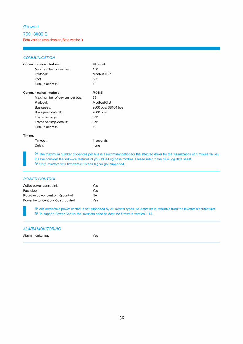
Growatt
750~3000 SBeta version (see chapter „Beta version“)
COMMUNICATION
Communication interface: Ethernet
Max. number of devices: 100
Protocol: ModbusTCP
Port: 502
Default address: 1
Communication interface: RS485
Max. number of devices per bus: 32
Protocol: ModbusRTU
Bus speed: 9600 bps, 38400 bps
Bus speed default: 9600 bps
Frame settings: 8N1
Frame settings default: 8N1
Default address: 1
Timings
Timeout: 1 seconds
Delay: none
The maximum number of devices per bus is a recommendation for the affected driver for the visualization of 1-minute values.
Please consider the software features of your blue’Log base module. Please refer to the blue’Log data sheet.
Only inverters with firmware 3.15 and higher get supported.
POWER CONTROL
Active power constraint: Yes
Fast stop: Yes
Reactive power control - Q control: No
Power factor control - Cos φ control: Yes
Active/reactive power control is not supported by all inverter types. An exact list is available from the inverter manufacturer.
To support Power Control the inverters need at least the firmware version 3.15.
ALARM MONITORING
Alarm monitoring: Yes
56

MEASUREMENT VALUES RECORDED
ERROR (1,...x) Error (1,...x)
E_DAY Energy generated per day
E_TOTAL Energy total
F_AC Grid frequency
I_AC1 Current AC phase 1
I_AC2 Current AC phase 2
I_AC3 Current AC phase 3
I_DC (1,...x) Current DC string (1,...x)
I_DCX_Y Current DC (1,...x).(1,...x)
OT_AC_TOTAL Total operating hours
P_AC Power AC
P_AC1 Power AC phase 1
P_AC2 Power AC phase 2
P_AC3 Power AC phase 3
P_DC Power DC
P_DC (1,...x) Power DC string (1,...x)
Q_AC Reactive power
STATE (1,...x) Status (1,...x)
T (1,...x) Temperature (1,...x)
U_AC1 Voltage AC phase 1
U_AC2 Voltage AC phase 2
U_AC3 Voltage AC phase 3
U_DC (1,...x) Voltage DC string (1,...x)
The actually recorded values may vary due to the device model or the device firmware.
Monitoring of DC inputs from Growatt inverters available from inverter firmware version 3.10 on.
SUPPORTED DEVICES
750~3000 S series
750-S 1000-S 1500-S
2000-S 2500-S 3000-S
Please contact Sales for details of compatibility with devices not listed.
Phone: +49 (0)821 34666 - 80
E-mail: [email protected]
57

2500~5500 MTL-SBeta version (see chapter „Beta version“)
COMMUNICATION
Communication interface: Ethernet
Max. number of devices: 100
Protocol: ModbusTCP
Port: 502
Default address: 1
Communication interface: RS485
Max. number of devices per bus: 32
Protocol: ModbusRTU
Bus speed: 9600 bps, 38400 bps
Bus speed default: 9600 bps
Frame settings: 8N1
Frame settings default: 8N1
Default address: 1
Timings
Timeout: 1 seconds
Delay: none
The maximum number of devices per bus is a recommendation for the affected driver for the visualization of 1-minute values.
Please consider the software features of your blue’Log base module. Please refer to the blue’Log data sheet.
Only inverters with firmware 3.15 and higher get supported.
POWER CONTROL
Active power constraint: Yes
Fast stop: Yes
Reactive power control - Q control: No
Power factor control - Cos φ control: Yes
Active/reactive power control is not supported by all inverter types. An exact list is available from the inverter manufacturer.
To support Power Control the inverters need at least the firmware version 3.15.
ALARM MONITORING
Alarm monitoring: Yes
58

MEASUREMENT VALUES RECORDED
ERROR (1,...x) Error (1,...x)
E_DAY Energy generated per day
E_TOTAL Energy total
F_AC Grid frequency
I_AC1 Current AC phase 1
I_AC2 Current AC phase 2
I_AC3 Current AC phase 3
I_DC (1,...x) Current DC string (1,...x)
I_DCX_Y Current DC (1,...x).(1,...x)
OT_AC_TOTAL Total operating hours
P_AC Power AC
P_AC1 Power AC phase 1
P_AC2 Power AC phase 2
P_AC3 Power AC phase 3
P_DC Power DC
P_DC (1,...x) Power DC string (1,...x)
Q_AC Reactive power
STATE (1,...x) Status (1,...x)
T (1,...x) Temperature (1,...x)
U_AC1 Voltage AC phase 1
U_AC2 Voltage AC phase 2
U_AC3 Voltage AC phase 3
U_DC (1,...x) Voltage DC string (1,...x)
The actually recorded values may vary due to the device model or the device firmware.
Monitoring of DC inputs from Growatt inverters available from inverter firmware version 3.10 on.
SUPPORTED DEVICES
2500~5500 MTL-S series
2500MTL-S 3000MTL-S 3600MTL-S
4200MTL-S 5000MTL-S 5500MTL-S
Please contact Sales for details of compatibility with devices not listed.
Phone: +49 (0)821 34666 - 80
E-mail: [email protected]
59

3000~6000 TL3-SBeta version (see chapter „Beta version“)
COMMUNICATION
Communication interface: Ethernet
Max. number of devices: 100
Protocol: ModbusTCP
Port: 502
Default address: 1
Communication interface: RS485
Max. number of devices per bus: 32
Protocol: ModbusRTU
Bus speed: 9600 bps, 38400 bps
Bus speed default: 9600 bps
Frame settings: 8N1
Frame settings default: 8N1
Default address: 1
Timings
Timeout: 1 seconds
Delay: none
The maximum number of devices per bus is a recommendation for the affected driver for the visualization of 1-minute values.
Please consider the software features of your blue’Log base module. Please refer to the blue’Log data sheet.
Only inverters with firmware 3.15 and higher get supported.
POWER CONTROL
Active power constraint: Yes
Fast stop: Yes
Reactive power control - Q control: No
Power factor control - Cos φ control: Yes
Active/reactive power control is not supported by all inverter types. An exact list is available from the inverter manufacturer.
To support Power Control the inverters need at least the firmware version 3.15.
ALARM MONITORING
Alarm monitoring: Yes
60

MEASUREMENT VALUES RECORDED
ERROR (1,...x) Error (1,...x)
E_DAY Energy generated per day
E_TOTAL Energy total
F_AC Grid frequency
I_AC1 Current AC phase 1
I_AC2 Current AC phase 2
I_AC3 Current AC phase 3
I_DC (1,...x) Current DC string (1,...x)
I_DCX_Y Current DC (1,...x).(1,...x)
OT_AC_TOTAL Total operating hours
P_AC Power AC
P_AC1 Power AC phase 1
P_AC2 Power AC phase 2
P_AC3 Power AC phase 3
P_DC Power DC
P_DC (1,...x) Power DC string (1,...x)
Q_AC Reactive power
STATE (1,...x) Status (1,...x)
T (1,...x) Temperature (1,...x)
U_AC1 Voltage AC phase 1
U_AC2 Voltage AC phase 2
U_AC3 Voltage AC phase 3
U_DC (1,...x) Voltage DC string (1,...x)
The actually recorded values may vary due to the device model or the device firmware.
Monitoring of DC inputs from Growatt inverters available from inverter firmware version 3.10 on.
SUPPORTED DEVICES
3000~6000 TL3-S series
3000TL3-S 4000TL3-S 5000TL3-S
6000TL3-S
Please contact Sales for details of compatibility with devices not listed.
Phone: +49 (0)821 34666 - 80
E-mail: [email protected]
61

7000~11000 TL3-SBeta version (see chapter „Beta version“)
COMMUNICATION
Communication interface: Ethernet
Max. number of devices: 100
Protocol: ModbusTCP
Port: 502
Default address: 1
Communication interface: RS485
Max. number of devices per bus: 32
Protocol: ModbusRTU
Bus speed: 9600 bps, 38400 bps
Bus speed default: 9600 bps
Frame settings: 8N1
Frame settings default: 8N1
Default address: 1
Timings
Timeout: 1 seconds
Delay: none
The maximum number of devices per bus is a recommendation for the affected driver for the visualization of 1-minute values.
Please consider the software features of your blue’Log base module. Please refer to the blue’Log data sheet.
Only inverters with firmware 3.15 and higher get supported.
POWER CONTROL
Active power constraint: Yes
Fast stop: Yes
Reactive power control - Q control: No
Power factor control - Cos φ control: Yes
Active/reactive power control is not supported by all inverter types. An exact list is available from the inverter manufacturer.
To support Power Control the inverters need at least the firmware version 3.15.
ALARM MONITORING
Alarm monitoring: Yes
62
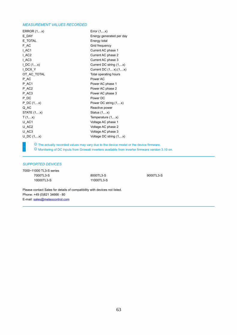
MEASUREMENT VALUES RECORDED
ERROR (1,...x) Error (1,...x)
E_DAY Energy generated per day
E_TOTAL Energy total
F_AC Grid frequency
I_AC1 Current AC phase 1
I_AC2 Current AC phase 2
I_AC3 Current AC phase 3
I_DC (1,...x) Current DC string (1,...x)
I_DCX_Y Current DC (1,...x).(1,...x)
OT_AC_TOTAL Total operating hours
P_AC Power AC
P_AC1 Power AC phase 1
P_AC2 Power AC phase 2
P_AC3 Power AC phase 3
P_DC Power DC
P_DC (1,...x) Power DC string (1,...x)
Q_AC Reactive power
STATE (1,...x) Status (1,...x)
T (1,...x) Temperature (1,...x)
U_AC1 Voltage AC phase 1
U_AC2 Voltage AC phase 2
U_AC3 Voltage AC phase 3
U_DC (1,...x) Voltage DC string (1,...x)
The actually recorded values may vary due to the device model or the device firmware.
Monitoring of DC inputs from Growatt inverters available from inverter firmware version 3.10 on.
SUPPORTED DEVICES
7000~11000 TL3-S series
7000TL3-S 8000TL3-S 9000TL3-S
10000TL3-S 11000TL3-S
Please contact Sales for details of compatibility with devices not listed.
Phone: +49 (0)821 34666 - 80
E-mail: [email protected]
63
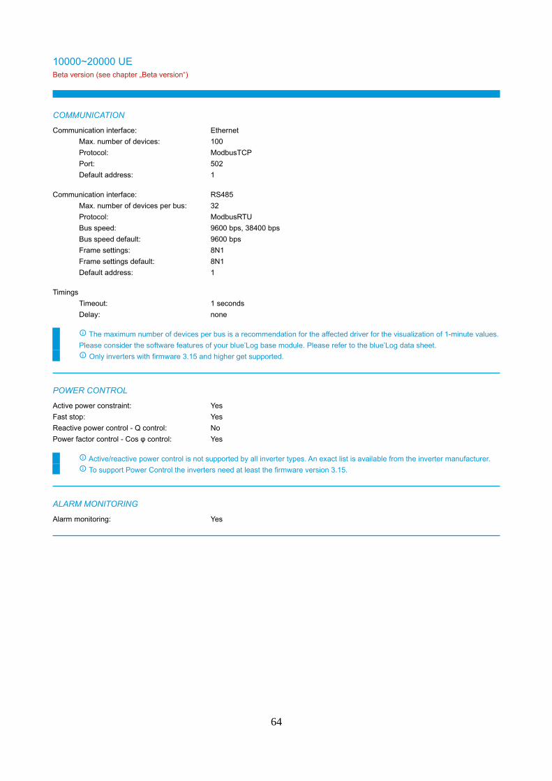
10000~20000 UEBeta version (see chapter „Beta version“)
COMMUNICATION
Communication interface: Ethernet
Max. number of devices: 100
Protocol: ModbusTCP
Port: 502
Default address: 1
Communication interface: RS485
Max. number of devices per bus: 32
Protocol: ModbusRTU
Bus speed: 9600 bps, 38400 bps
Bus speed default: 9600 bps
Frame settings: 8N1
Frame settings default: 8N1
Default address: 1
Timings
Timeout: 1 seconds
Delay: none
The maximum number of devices per bus is a recommendation for the affected driver for the visualization of 1-minute values.
Please consider the software features of your blue’Log base module. Please refer to the blue’Log data sheet.
Only inverters with firmware 3.15 and higher get supported.
POWER CONTROL
Active power constraint: Yes
Fast stop: Yes
Reactive power control - Q control: No
Power factor control - Cos φ control: Yes
Active/reactive power control is not supported by all inverter types. An exact list is available from the inverter manufacturer.
To support Power Control the inverters need at least the firmware version 3.15.
ALARM MONITORING
Alarm monitoring: Yes
64
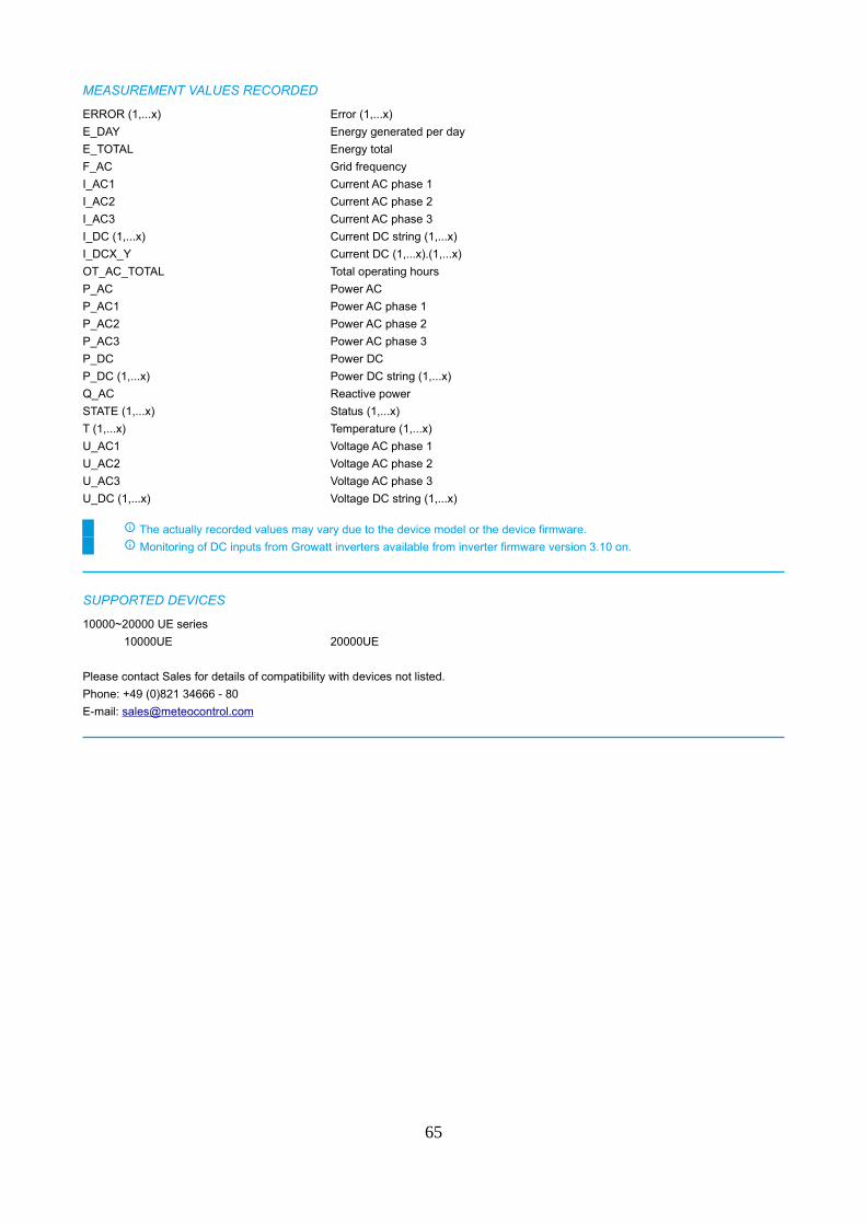
MEASUREMENT VALUES RECORDED
ERROR (1,...x) Error (1,...x)
E_DAY Energy generated per day
E_TOTAL Energy total
F_AC Grid frequency
I_AC1 Current AC phase 1
I_AC2 Current AC phase 2
I_AC3 Current AC phase 3
I_DC (1,...x) Current DC string (1,...x)
I_DCX_Y Current DC (1,...x).(1,...x)
OT_AC_TOTAL Total operating hours
P_AC Power AC
P_AC1 Power AC phase 1
P_AC2 Power AC phase 2
P_AC3 Power AC phase 3
P_DC Power DC
P_DC (1,...x) Power DC string (1,...x)
Q_AC Reactive power
STATE (1,...x) Status (1,...x)
T (1,...x) Temperature (1,...x)
U_AC1 Voltage AC phase 1
U_AC2 Voltage AC phase 2
U_AC3 Voltage AC phase 3
U_DC (1,...x) Voltage DC string (1,...x)
The actually recorded values may vary due to the device model or the device firmware.
Monitoring of DC inputs from Growatt inverters available from inverter firmware version 3.10 on.
SUPPORTED DEVICES
10000~20000 UE series
10000UE 20000UE
Please contact Sales for details of compatibility with devices not listed.
Phone: +49 (0)821 34666 - 80
E-mail: [email protected]
65

12000~15000 TL3-SBeta version (see chapter „Beta version“)
COMMUNICATION
Communication interface: Ethernet
Max. number of devices: 100
Protocol: ModbusTCP
Port: 502
Default address: 1
Communication interface: RS485
Max. number of devices per bus: 32
Protocol: ModbusRTU
Bus speed: 9600 bps, 38400 bps
Bus speed default: 9600 bps
Frame settings: 8N1
Frame settings default: 8N1
Default address: 1
Timings
Timeout: 1 seconds
Delay: none
The maximum number of devices per bus is a recommendation for the affected driver for the visualization of 1-minute values.
Please consider the software features of your blue’Log base module. Please refer to the blue’Log data sheet.
Only inverters with firmware 3.15 and higher get supported.
POWER CONTROL
Active power constraint: Yes
Fast stop: Yes
Reactive power control - Q control: No
Power factor control - Cos φ control: Yes
Active/reactive power control is not supported by all inverter types. An exact list is available from the inverter manufacturer.
To support Power Control the inverters need at least the firmware version 3.15.
ALARM MONITORING
Alarm monitoring: Yes
66
MEASUREMENT VALUES RECORDED
ERROR (1,...x) Error (1,...x)
E_DAY Energy generated per day
E_TOTAL Energy total
F_AC Grid frequency
I_AC1 Current AC phase 1
I_AC2 Current AC phase 2
I_AC3 Current AC phase 3
I_DC (1,...x) Current DC string (1,...x)
I_DCX_Y Current DC (1,...x).(1,...x)
OT_AC_TOTAL Total operating hours
P_AC Power AC
P_AC1 Power AC phase 1
P_AC2 Power AC phase 2
P_AC3 Power AC phase 3
P_DC Power DC
P_DC (1,...x) Power DC string (1,...x)
Q_AC Reactive power
STATE (1,...x) Status (1,...x)
T (1,...x) Temperature (1,...x)
U_AC1 Voltage AC phase 1
U_AC2 Voltage AC phase 2
U_AC3 Voltage AC phase 3
U_DC (1,...x) Voltage DC string (1,...x)
The actually recorded values may vary due to the device model or the device firmware.
Monitoring of DC inputs from Growatt inverters available from inverter firmware version 3.10 on.
SUPPORTED DEVICES
12000~15000 TL3-S series
12000TL3-S 13000TL3-S 15000TL3-S
Please contact Sales for details of compatibility with devices not listed.
Phone: +49 (0)821 34666 - 80
E-mail: [email protected]
67

17000~25000 TL3-SBeta version (see chapter „Beta version“)
COMMUNICATION
Communication interface: Ethernet
Max. number of devices: 100
Protocol: ModbusTCP
Port: 502
Default address: 1
Communication interface: RS485
Max. number of devices per bus: 32
Protocol: ModbusRTU
Bus speed: 9600 bps, 38400 bps
Bus speed default: 9600 bps
Frame settings: 8N1
Frame settings default: 8N1
Default address: 1
Timings
Timeout: 1 seconds
Delay: none
The maximum number of devices per bus is a recommendation for the affected driver for the visualization of 1-minute values.
Please consider the software features of your blue’Log base module. Please refer to the blue’Log data sheet.
Only inverters with firmware 3.15 and higher get supported.
POWER CONTROL
Active power constraint: Yes
Fast stop: Yes
Reactive power control - Q control: No
Power factor control - Cos φ control: Yes
Active/reactive power control is not supported by all inverter types. An exact list is available from the inverter manufacturer.
To support Power Control the inverters need at least the firmware version 3.15.
ALARM MONITORING
Alarm monitoring: Yes
68

MEASUREMENT VALUES RECORDED
ERROR (1,...x) Error (1,...x)
E_DAY Energy generated per day
E_TOTAL Energy total
F_AC Grid frequency
I_AC1 Current AC phase 1
I_AC2 Current AC phase 2
I_AC3 Current AC phase 3
I_DC (1,...x) Current DC string (1,...x)
I_DCX_Y Current DC (1,...x).(1,...x)
OT_AC_TOTAL Total operating hours
P_AC Power AC
P_AC1 Power AC phase 1
P_AC2 Power AC phase 2
P_AC3 Power AC phase 3
P_DC Power DC
P_DC (1,...x) Power DC string (1,...x)
Q_AC Reactive power
STATE (1,...x) Status (1,...x)
T (1,...x) Temperature (1,...x)
U_AC1 Voltage AC phase 1
U_AC2 Voltage AC phase 2
U_AC3 Voltage AC phase 3
U_DC (1,...x) Voltage DC string (1,...x)
The actually recorded values may vary due to the device model or the device firmware.
Monitoring of DC inputs from Growatt inverters available from inverter firmware version 3.10 on.
SUPPORTED DEVICES
17000~25000 TL3-S series
17000TL3-S 20000TL3-S 25000TL3-S
Please contact Sales for details of compatibility with devices not listed.
Phone: +49 (0)821 34666 - 80
E-mail: [email protected]
69

30000~50000 TL3-SBeta version (see chapter „Beta version“)
COMMUNICATION
Communication interface: Ethernet
Max. number of devices: 100
Protocol: ModbusTCP
Port: 502
Default address: 1
Communication interface: RS485
Max. number of devices per bus: 32
Protocol: ModbusRTU
Bus speed: 9600 bps, 38400 bps
Bus speed default: 9600 bps
Frame settings: 8N1
Frame settings default: 8N1
Default address: 1
Timings
Timeout: 1 seconds
Delay: none
The maximum number of devices per bus is a recommendation for the affected driver for the visualization of 1-minute values.
Please consider the software features of your blue’Log base module. Please refer to the blue’Log data sheet.
Only inverters with firmware 3.15 and higher get supported.
POWER CONTROL
Active power constraint: Yes
Fast stop: Yes
Reactive power control - Q control: No
Power factor control - Cos φ control: Yes
Active/reactive power control is not supported by all inverter types. An exact list is available from the inverter manufacturer.
To support Power Control the inverters need at least the firmware version 3.15.
ALARM MONITORING
Alarm monitoring: Yes
70
MEASUREMENT VALUES RECORDED
ERROR (1,...x) Error (1,...x)
E_DAY Energy generated per day
E_TOTAL Energy total
F_AC Grid frequency
I_AC1 Current AC phase 1
I_AC2 Current AC phase 2
I_AC3 Current AC phase 3
I_DC (1,...x) Current DC string (1,...x)
I_DCX_Y Current DC (1,...x).(1,...x)
OT_AC_TOTAL Total operating hours
P_AC Power AC
P_AC1 Power AC phase 1
P_AC2 Power AC phase 2
P_AC3 Power AC phase 3
P_DC Power DC
P_DC (1,...x) Power DC string (1,...x)
Q_AC Reactive power
STATE (1,...x) Status (1,...x)
T (1,...x) Temperature (1,...x)
U_AC1 Voltage AC phase 1
U_AC2 Voltage AC phase 2
U_AC3 Voltage AC phase 3
U_DC (1,...x) Voltage DC string (1,...x)
The actually recorded values may vary due to the device model or the device firmware.
Monitoring of DC inputs from Growatt inverters available from inverter firmware version 3.10 on.
SUPPORTED DEVICES
30000~50000 TL3-S series
30000TL3-S 33000TL3-S 40000TL3-S
50000TL3-S
Please contact Sales for details of compatibility with devices not listed.
Phone: +49 (0)821 34666 - 80
E-mail: [email protected]
71
MAX xx KTL3 LV/MVBeta version (see chapter „Beta version“)
COMMUNICATION
Communication interface: Ethernet
Max. number of devices: 100
Protocol: ModbusTCP
Port: 502
Default address: 1
Communication interface: RS485
Max. number of devices per bus: 23
Protocol: ModbusRTU
Bus speed: 9600 bps, 38400 bps
Bus speed default: 9600 bps
Frame settings: 8N1
Frame settings default: 8N1
Default address: 1
Timings
Timeout: 1 seconds
Delay: none
The maximum number of devices per bus is a recommendation for the affected driver for the visualization of 1-minute values.
Please consider the software features of your blue’Log base module. Please refer to the blue’Log data sheet.
POWER CONTROL
Active power constraint: Yes
Fast stop: Yes
Reactive power control - Q control: No
Power factor control - Cos φ control: Yes
Active/reactive power control is not supported by all inverter types. An exact list is available from the inverter manufacturer.
ALARM MONITORING
Alarm monitoring: Yes
72
MEASUREMENT VALUES RECORDED
ERROR (1,...x) Error (1,...x)
E_DAY Energy generated per day
E_TOTAL Energy total
F_AC Grid frequency
I_AC1 Current AC phase 1
I_AC2 Current AC phase 2
I_AC3 Current AC phase 3
I_DC (1,...x) Current DC string (1,...x)
I_DCX_Y Current DC (1,...x).(1,...x)
OT_AC_TOTAL Total operating hours
P_AC Power AC
P_AC1 Power AC phase 1
P_AC2 Power AC phase 2
P_AC3 Power AC phase 3
P_DC Power DC
P_DC (1,...x) Power DC string (1,...x)
STATE (1,...x) Status (1,...x)
T (1,...x) Temperature (1,...x)
U_AC1 Voltage AC phase 1
U_AC2 Voltage AC phase 2
U_AC3 Voltage AC phase 3
U_AC_L1L2 Phase voltage L1L2
U_AC_L2L3 Phase voltage L2L3
U_AC_L3L1 Phase voltage L3L1
U_DC (1,...x) Voltage DC string (1,...x)
The actually recorded values may vary due to the device model or the device firmware.
Please note that the driver does not support Battery values.
SUPPORTED DEVICES
MAX xx KTL3 LV/MV series
MAX 50KTL3 LV MAX 60KTL3 LV MAX 60KTL3 MV
MAX 70KTL3 LV MAX 70KTL3 MV MAX 80KTL3 LV
MAX 80KTL3 MV
Please contact Sales for details of compatibility with devices not listed.
Phone: +49 (0)821 34666 - 80
E-mail: [email protected]
73

SPA xxxx TL-BLBeta version (see chapter „Beta version“)
COMMUNICATION
Communication interface: Ethernet
Max. number of devices: 100
Protocol: ModbusTCP
Port: 502
Default address: 1
Communication interface: RS485
Max. number of devices per bus: 23
Protocol: ModbusRTU
Bus speed: 9600 bps, 38400 bps
Bus speed default: 9600 bps
Frame settings: 8N1
Frame settings default: 8N1
Default address: 1
Timings
Timeout: 1 seconds
Delay: none
The maximum number of devices per bus is a recommendation for the affected driver for the visualization of 1-minute values.
Please consider the software features of your blue’Log base module. Please refer to the blue’Log data sheet.
POWER CONTROL
Active power constraint: Yes
Fast stop: Yes
Reactive power control - Q control: No
Power factor control - Cos φ control: Yes
Active/reactive power control is not supported by all inverter types. An exact list is available from the inverter manufacturer.
ALARM MONITORING
Alarm monitoring: Yes
74
MEASUREMENT VALUES RECORDED
ERROR (1,...x) Error (1,...x)
E_DAY Energy generated per day
E_TOTAL Energy total
F_AC Grid frequency
I_AC1 Current AC phase 1
I_AC2 Current AC phase 2
I_AC3 Current AC phase 3
I_DC (1,...x) Current DC string (1,...x)
I_DCX_Y Current DC (1,...x).(1,...x)
OT_AC_TOTAL Total operating hours
P_AC Power AC
P_AC1 Power AC phase 1
P_AC2 Power AC phase 2
P_AC3 Power AC phase 3
P_DC Power DC
P_DC (1,...x) Power DC string (1,...x)
STATE (1,...x) Status (1,...x)
T (1,...x) Temperature (1,...x)
U_AC1 Voltage AC phase 1
U_AC2 Voltage AC phase 2
U_AC3 Voltage AC phase 3
U_AC_L1L2 Phase voltage L1L2
U_AC_L2L3 Phase voltage L2L3
U_AC_L3L1 Phase voltage L3L1
U_DC (1,...x) Voltage DC string (1,...x)
The actually recorded values may vary due to the device model or the device firmware.
Please note that the driver does not support Battery values.
SUPPORTED DEVICES
SPA xxxx TL-BL series
SPA1000TL-BL SPA2000TL-BL SPA3000TL-BL
Please contact Sales for details of compatibility with devices not listed.
Phone: +49 (0)821 34666 - 80
E-mail: [email protected]
75
SPA xxxx TL3-BHBeta version (see chapter „Beta version“)
COMMUNICATION
Communication interface: Ethernet
Max. number of devices: 100
Protocol: ModbusTCP
Port: 502
Default address: 1
Communication interface: RS485
Max. number of devices per bus: 23
Protocol: ModbusRTU
Bus speed: 9600 bps, 38400 bps
Bus speed default: 9600 bps
Frame settings: 8N1
Frame settings default: 8N1
Default address: 1
Timings
Timeout: 1 seconds
Delay: none
The maximum number of devices per bus is a recommendation for the affected driver for the visualization of 1-minute values.
Please consider the software features of your blue’Log base module. Please refer to the blue’Log data sheet.
POWER CONTROL
Active power constraint: Yes
Fast stop: Yes
Reactive power control - Q control: No
Power factor control - Cos φ control: Yes
Active/reactive power control is not supported by all inverter types. An exact list is available from the inverter manufacturer.
ALARM MONITORING
Alarm monitoring: Yes
76

MEASUREMENT VALUES RECORDED
ERROR (1,...x) Error (1,...x)
E_DAY Energy generated per day
E_TOTAL Energy total
F_AC Grid frequency
I_AC1 Current AC phase 1
I_AC2 Current AC phase 2
I_AC3 Current AC phase 3
I_DC (1,...x) Current DC string (1,...x)
I_DCX_Y Current DC (1,...x).(1,...x)
OT_AC_TOTAL Total operating hours
P_AC Power AC
P_AC1 Power AC phase 1
P_AC2 Power AC phase 2
P_AC3 Power AC phase 3
P_DC Power DC
P_DC (1,...x) Power DC string (1,...x)
STATE (1,...x) Status (1,...x)
T (1,...x) Temperature (1,...x)
U_AC1 Voltage AC phase 1
U_AC2 Voltage AC phase 2
U_AC3 Voltage AC phase 3
U_AC_L1L2 Phase voltage L1L2
U_AC_L2L3 Phase voltage L2L3
U_AC_L3L1 Phase voltage L3L1
U_DC (1,...x) Voltage DC string (1,...x)
The actually recorded values may vary due to the device model or the device firmware.
Please note that the driver does not support Battery values.
SUPPORTED DEVICES
SPA xxxx TL3-BH series
SPA 4000 TL3 BH SPA 5000 TL3 BH SPA 6000 TL3 BH
SPA 7000 TL3 BH SPA 8000 TL3 BH SPA 10000 TL3 BH
Please contact Sales for details of compatibility with devices not listed.
Phone: +49 (0)821 34666 - 80
E-mail: [email protected]
77
SPH xxxxBeta version (see chapter „Beta version“)
COMMUNICATION
Communication interface: Ethernet
Max. number of devices: 100
Protocol: ModbusTCP
Port: 502
Default address: 1
Communication interface: RS485
Max. number of devices per bus: 23
Protocol: ModbusRTU
Bus speed: 9600 bps, 38400 bps
Bus speed default: 9600 bps
Frame settings: 8N1
Frame settings default: 8N1
Default address: 1
Timings
Timeout: 1 seconds
Delay: none
The maximum number of devices per bus is a recommendation for the affected driver for the visualization of 1-minute values.
Please consider the software features of your blue’Log base module. Please refer to the blue’Log data sheet.
POWER CONTROL
Active power constraint: Yes
Fast stop: Yes
Reactive power control - Q control: No
Power factor control - Cos φ control: Yes
Active/reactive power control is not supported by all inverter types. An exact list is available from the inverter manufacturer.
ALARM MONITORING
Alarm monitoring: Yes
78
MEASUREMENT VALUES RECORDED
ERROR (1,...x) Error (1,...x)
E_DAY Energy generated per day
E_TOTAL Energy total
F_AC Grid frequency
I_AC1 Current AC phase 1
I_AC2 Current AC phase 2
I_AC3 Current AC phase 3
I_DC (1,...x) Current DC string (1,...x)
I_DCX_Y Current DC (1,...x).(1,...x)
OT_AC_TOTAL Total operating hours
P_AC Power AC
P_AC1 Power AC phase 1
P_AC2 Power AC phase 2
P_AC3 Power AC phase 3
P_DC Power DC
P_DC (1,...x) Power DC string (1,...x)
STATE (1,...x) Status (1,...x)
T (1,...x) Temperature (1,...x)
U_AC1 Voltage AC phase 1
U_AC2 Voltage AC phase 2
U_AC3 Voltage AC phase 3
U_AC_L1L2 Phase voltage L1L2
U_AC_L2L3 Phase voltage L2L3
U_AC_L3L1 Phase voltage L3L1
U_DC (1,...x) Voltage DC string (1,...x)
The actually recorded values may vary due to the device model or the device firmware.
Please note that the driver does not support Battery values.
SUPPORTED DEVICES
SPH xxxx series
SPH3000 SPH3600 SPH4000
SPH4600 SPH5000 SPH6000
Please contact Sales for details of compatibility with devices not listed.
Phone: +49 (0)821 34666 - 80
E-mail: [email protected]
79
SPH xxxx TL3-BHBeta version (see chapter „Beta version“)
COMMUNICATION
Communication interface: Ethernet
Max. number of devices: 100
Protocol: ModbusTCP
Port: 502
Default address: 1
Communication interface: RS485
Max. number of devices per bus: 23
Protocol: ModbusRTU
Bus speed: 9600 bps, 38400 bps
Bus speed default: 9600 bps
Frame settings: 8N1
Frame settings default: 8N1
Default address: 1
Timings
Timeout: 1 seconds
Delay: none
The maximum number of devices per bus is a recommendation for the affected driver for the visualization of 1-minute values.
Please consider the software features of your blue’Log base module. Please refer to the blue’Log data sheet.
POWER CONTROL
Active power constraint: Yes
Fast stop: Yes
Reactive power control - Q control: No
Power factor control - Cos φ control: Yes
Active/reactive power control is not supported by all inverter types. An exact list is available from the inverter manufacturer.
ALARM MONITORING
Alarm monitoring: Yes
80
MEASUREMENT VALUES RECORDED
ERROR (1,...x) Error (1,...x)
E_DAY Energy generated per day
E_TOTAL Energy total
F_AC Grid frequency
I_AC1 Current AC phase 1
I_AC2 Current AC phase 2
I_AC3 Current AC phase 3
I_DC (1,...x) Current DC string (1,...x)
I_DCX_Y Current DC (1,...x).(1,...x)
OT_AC_TOTAL Total operating hours
P_AC Power AC
P_AC1 Power AC phase 1
P_AC2 Power AC phase 2
P_AC3 Power AC phase 3
P_DC Power DC
P_DC (1,...x) Power DC string (1,...x)
STATE (1,...x) Status (1,...x)
T (1,...x) Temperature (1,...x)
U_AC1 Voltage AC phase 1
U_AC2 Voltage AC phase 2
U_AC3 Voltage AC phase 3
U_AC_L1L2 Phase voltage L1L2
U_AC_L2L3 Phase voltage L2L3
U_AC_L3L1 Phase voltage L3L1
U_DC (1,...x) Voltage DC string (1,...x)
The actually recorded values may vary due to the device model or the device firmware.
Please note that the driver does not support Battery values.
SUPPORTED DEVICES
SPH xxxx TL3-BH series
SPH4000TL3 BH SPH5000TL3 BH SPH6000TL3 BH
SPH7000TL3 BH SPH8000TL3 BH SPH10000TL3 BH
Please contact Sales for details of compatibility with devices not listed.
Phone: +49 (0)821 34666 - 80
E-mail: [email protected]
81
Huawei
SUN2000
COMMUNICATION
Communication interface: Ethernet
Max. number of devices: 100
Protocol: ModbusTCP
Port: 502
Default address: 0
Communication interface: RS485
Max. number of devices per bus: 41
Protocol: ModbusRTU
Bus speed: 4800 bps, 9600 bps, 19200 bps
Bus speed default: 9600 bps
Frame settings: 8N1, 8E1
Frame settings default: 8N1
Default address: 1
Timings
Timeout: 5 seconds
Delay: none
The maximum number of devices per bus is a recommendation for the affected driver for the visualization of 1-minute values.
Please consider the software features of your blue’Log base module. Please refer to the blue’Log data sheet.
Direct connection of Huawei inverters to blue’Log via RS485 (Modbus RTU).
When using Huawei SmartLogger:
- connection of SmartLogger to blue’Log via Ethernet (Modbus TCP)
- blue’Log needs to be registered in the "Whitelist" of the SmartLogger
- set on the Smartlogger in section Settings/Modbus TCP/Link setting "Enable(Unlimited)" and enter IP address of the blue’Log
- SmartLogger address needs to be set to 0
POWER CONTROL
Active power constraint: Yes
Fast stop: Yes
Reactive power control - Q control: Yes
Power factor control - Cos φ control: Yes
Active/reactive power control is not supported by all inverter types. An exact list is available from the inverter manufacturer.
If inverters connected to SmartLogger "Enable" Active/Reactive power control in Settings of SmartLogger.
Set "Active/Reactive power control mode" to: "Remote scheduling" on the SmartLogger.
ALARM MONITORING
Alarm monitoring: Yes
82
MEASUREMENT VALUES RECORDED
COS_PHI Power factor (cos phi)
ERROR (1,...x) Error (1,...x)
E_DAY Energy generated per day
E_TOTAL Energy total
F_AC Grid frequency
I_AC1 Current AC phase 1
I_AC2 Current AC phase 2
I_AC3 Current AC phase 3
I_DC (1,...x) Current DC string (1,...x)
I_DCX_Y Current DC (1,...x).(1,...x)
P_AC Power AC
P_DC Power DC
P_DC (1,...x) Power DC string (1,...x)
Q_AC Reactive power
R_ISO Insulation resistance
STATE (1,...x) Status (1,...x)
T Temperature
U_AC1 Voltage AC phase 1
U_AC2 Voltage AC phase 2
U_AC3 Voltage AC phase 3
U_AC_L1L2 Phase voltage L1L2
U_AC_L2L3 Phase voltage L2L3
U_AC_L3L1 Phase voltage L3L1
U_DC (1,...x) Voltage DC string (1,...x)
The actually recorded values may vary due to the device model or the device firmware.
83
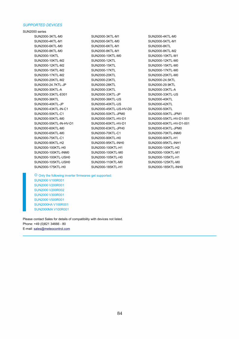
SUPPORTED DEVICES
SUN2000 series
SUN2000-3KTL-M0 SUN2000-3KTL-M1 SUN2000-4KTL-M0
SUN2000-4KTL-M1 SUN2000-5KTL-M0 SUN2000-5KTL-M1
SUN2000-6KTL-M0 SUN2000-6KTL-M1 SUN2000-8KTL
SUN2000-8KTL-M0 SUN2000-8KTL-M1 SUN2000-8KTL-M2
SUN2000-10KTL SUN2000-10KTL-M0 SUN2000-10KTL-M1
SUN2000-10KTL-M2 SUN2000-12KTL SUN2000-12KTL-M0
SUN2000-12KTL-M2 SUN2000-15KTL SUN2000-15KTL-M0
SUN2000-15KTL-M2 SUN2000-17KTL SUN2000-17KTL-M0
SUN2000-17KTL-M2 SUN2000-20KTL SUN2000-20KTL-M0
SUN2000-20KTL-M2 SUN2000-23KTL SUN2000-24.5KTL
SUN2000-24.7KTL-JP SUN2000-28KTL SUN2000-29.9KTL
SUN2000-30KTL-A SUN2000-33KTL SUN2000-33KTL-A
SUN2000-33KTL-E001 SUN2000-33KTL-JP SUN2000-33KTL-US
SUN2000-36KTL SUN2000-36KTL-US SUN2000-40KTL
SUN2000-40KTL-JP SUN2000-40KTL-US SUN2000-42KTL
SUN2000-43KTL-IN-C1 SUN2000-45KTL-US-HV-D0 SUN2000-50KTL
SUN2000-50KTL-C1 SUN2000-50KTL-JPM0 SUN2000-50KTL-JPM1
SUN2000-50KTL-M0 SUN2000-55KTL-HV-D1 SUN2000-55KTL-HV-D1-001
SUN2000-55KTL-IN-HV-D1 SUN2000-60KTL-HV-D1 SUN2000-60KTL-HV-D1-001
SUN2000-60KTL-M0 SUN2000-63KTL-JPH0 SUN2000-63KTL-JPM0
SUN2000-65KTL-M0 SUN2000-70KTL-C1 SUN2000-70KTL-INM0
SUN2000-75KTL-C1 SUN2000-90KTL-H0 SUN2000-90KTL-H1
SUN2000-90KTL-H2 SUN2000-95KTL-INH0 SUN2000-95KTL-INH1
SUN2000-100KTL-H0 SUN2000-100KTL-H1 SUN2000-100KTL-H2
SUN2000-100KTL-INM0 SUN2000-100KTL-M0 SUN2000-100KTL-M1
SUN2000-100KTL-USH0 SUN2000-105KTL-H0 SUN2000-105KTL-H1
SUN2000-105KTL-USH0 SUN2000-110KTL-M0 SUN2000-125KTL-M0
SUN2000-175KTL-H0 SUN2000-185KTL-H1 SUN2000-185KTL-INH0
Only the following inverter firmwares get supported:
SUN2000 V100R001
SUN2000 V200R001
SUN2000 V200R002
SUN2000 V300R001
SUN2000 V500R001
SUN2000HA V100R001
SUN2000MA V100R001
Please contact Sales for details of compatibility with devices not listed.
Phone: +49 (0)821 34666 - 80
E-mail: [email protected]
84
SUN2000LBeta version (see chapter „Beta version“)
COMMUNICATION
Communication interface: Ethernet
Max. number of devices: 100
Protocol: ModbusTCP
Port: 502
Default address: 1
Timings
Timeout: 1 seconds
Delay: none
The maximum number of devices per bus is a recommendation for the affected driver for the visualization of 1-minute values.
Please consider the software features of your blue’Log base module. Please refer to the blue’Log data sheet.
POWER CONTROL
Active power constraint: Yes
Fast stop: Yes
Reactive power control - Q control: Yes
Power factor control - Cos φ control: Yes
Active/reactive power control is not supported by all inverter types. An exact list is available from the inverter manufacturer.
ALARM MONITORING
Alarm monitoring: Yes
MEASUREMENT VALUES RECORDED
COS_PHI Power factor (cos phi)
ERROR (1,...x) Error (1,...x)
E_TOTAL Energy total
F_AC Grid frequency
I_AC1 Current AC phase 1
I_DCX_Y Current DC (1,...x).(1,...x)
P_AC Power AC
P_DC Power DC
Q_AC Reactive power
R_ISO Insulation resistance
STATE (1,...x) Status (1,...x)
T Temperature
U_AC Voltage AC
U_DC (1,...x) Voltage DC string (1,...x)
The actually recorded values may vary due to the device model or the device firmware.
85

SUPPORTED DEVICES
SUN2000L series
SUN2000-2KTL SUN2000-2KTL-L0 SUN2000-3.68KTL
SUN2000-3KTL SUN2000-3KTL-CN SUN2000-3KTL-CN-4G
SUN2000-3KTL-L0 SUN2000-4.6KTL SUN2000-4KTL
SUN2000-4KTL-CN SUN2000-4KTL-CN-4G SUN2000-4KTL-L0
SUN2000-5KTL SUN2000-5KTL-CN SUN2000-5KTL-CN-4G
SUN2000-5KTL-L0
Please contact Sales for details of compatibility with devices not listed.
Phone: +49 (0)821 34666 - 80
E-mail: [email protected]
86
Ingeteam
Ingecon SUNBeta version (see chapter „Beta version“)
COMMUNICATION
Communication interface: Ethernet
Max. number of devices: 100
Protocol: ModbusTCP
Port: 502
Default address: 1
Communication interface: RS485
Max. number of devices per bus: 77
Protocol: ModbusRTU
Bus speed: 1200 bps, 2400 bps, 4800 bps, 9600 bps, 19200 bps, 38400 bps, 57600 bps,
115200 bps
Bus speed default: 9600 bps
Frame settings: 8N1
Frame settings default: 8N1
Default address: 1
Timings
Timeout: 2 seconds
Delay: none
The maximum number of devices per bus is a recommendation for the affected driver for the visualization of 1-minute values.
Please consider the software features of your blue’Log base module. Please refer to the blue’Log data sheet.
POWER CONTROL
Active power constraint: Yes
Fast stop: Yes
Reactive power control - Q control: Yes
Power factor control - Cos φ control: Yes
Active/reactive power control is not supported by all inverter types. An exact list is available from the inverter manufacturer.
ALARM MONITORING
Alarm monitoring: Yes
87
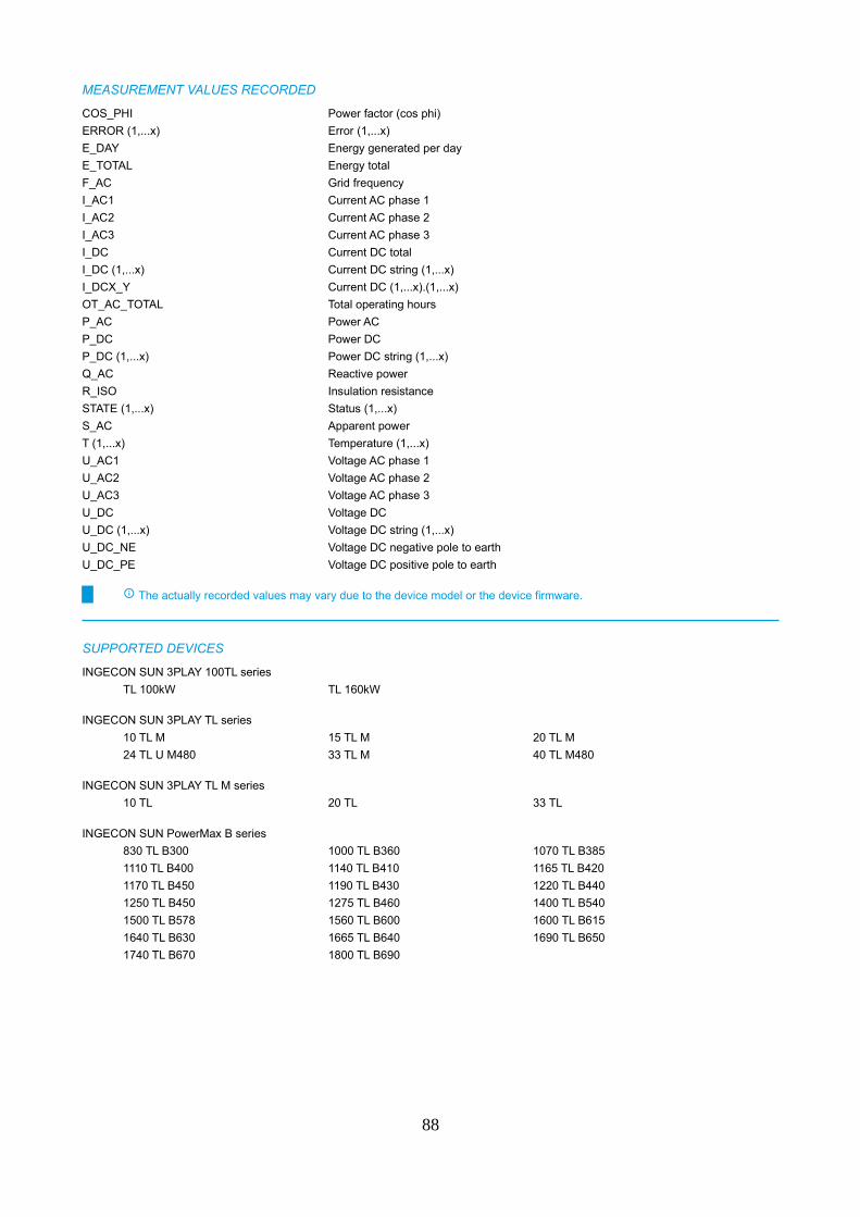
MEASUREMENT VALUES RECORDED
COS_PHI Power factor (cos phi)
ERROR (1,...x) Error (1,...x)
E_DAY Energy generated per day
E_TOTAL Energy total
F_AC Grid frequency
I_AC1 Current AC phase 1
I_AC2 Current AC phase 2
I_AC3 Current AC phase 3
I_DC Current DC total
I_DC (1,...x) Current DC string (1,...x)
I_DCX_Y Current DC (1,...x).(1,...x)
OT_AC_TOTAL Total operating hours
P_AC Power AC
P_DC Power DC
P_DC (1,...x) Power DC string (1,...x)
Q_AC Reactive power
R_ISO Insulation resistance
STATE (1,...x) Status (1,...x)
S_AC Apparent power
T (1,...x) Temperature (1,...x)
U_AC1 Voltage AC phase 1
U_AC2 Voltage AC phase 2
U_AC3 Voltage AC phase 3
U_DC Voltage DC
U_DC (1,...x) Voltage DC string (1,...x)
U_DC_NE Voltage DC negative pole to earth
U_DC_PE Voltage DC positive pole to earth
The actually recorded values may vary due to the device model or the device firmware.
SUPPORTED DEVICES
INGECON SUN 3PLAY 100TL series
TL 100kW TL 160kW
INGECON SUN 3PLAY TL series
10 TL M 15 TL M 20 TL M
24 TL U M480 33 TL M 40 TL M480
INGECON SUN 3PLAY TL M series
10 TL 20 TL 33 TL
INGECON SUN PowerMax B series
830 TL B300 1000 TL B360 1070 TL B385
1110 TL B400 1140 TL B410 1165 TL B420
1170 TL B450 1190 TL B430 1220 TL B440
1250 TL B450 1275 TL B460 1400 TL B540
1500 TL B578 1560 TL B600 1600 TL B615
1640 TL B630 1665 TL B640 1690 TL B650
1740 TL B670 1800 TL B690
88
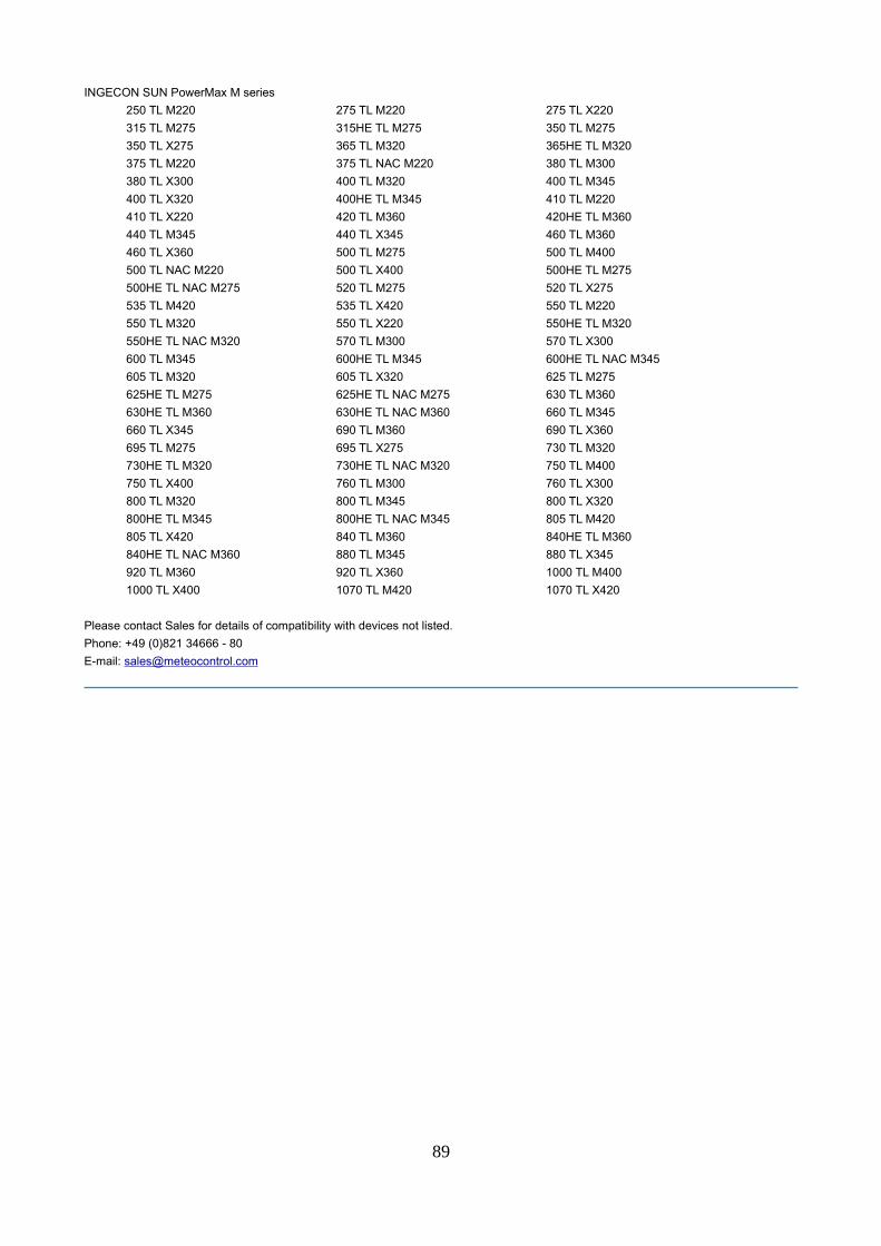
INGECON SUN PowerMax M series
250 TL M220 275 TL M220 275 TL X220
315 TL M275 315HE TL M275 350 TL M275
350 TL X275 365 TL M320 365HE TL M320
375 TL M220 375 TL NAC M220 380 TL M300
380 TL X300 400 TL M320 400 TL M345
400 TL X320 400HE TL M345 410 TL M220
410 TL X220 420 TL M360 420HE TL M360
440 TL M345 440 TL X345 460 TL M360
460 TL X360 500 TL M275 500 TL M400
500 TL NAC M220 500 TL X400 500HE TL M275
500HE TL NAC M275 520 TL M275 520 TL X275
535 TL M420 535 TL X420 550 TL M220
550 TL M320 550 TL X220 550HE TL M320
550HE TL NAC M320 570 TL M300 570 TL X300
600 TL M345 600HE TL M345 600HE TL NAC M345
605 TL M320 605 TL X320 625 TL M275
625HE TL M275 625HE TL NAC M275 630 TL M360
630HE TL M360 630HE TL NAC M360 660 TL M345
660 TL X345 690 TL M360 690 TL X360
695 TL M275 695 TL X275 730 TL M320
730HE TL M320 730HE TL NAC M320 750 TL M400
750 TL X400 760 TL M300 760 TL X300
800 TL M320 800 TL M345 800 TL X320
800HE TL M345 800HE TL NAC M345 805 TL M420
805 TL X420 840 TL M360 840HE TL M360
840HE TL NAC M360 880 TL M345 880 TL X345
920 TL M360 920 TL X360 1000 TL M400
1000 TL X400 1070 TL M420 1070 TL X420
Please contact Sales for details of compatibility with devices not listed.
Phone: +49 (0)821 34666 - 80
E-mail: [email protected]
89
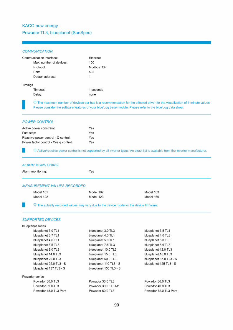
KACO new energy
Powador TL3, blueplanet (SunSpec)
COMMUNICATION
Communication interface: Ethernet
Max. number of devices: 100
Protocol: ModbusTCP
Port: 502
Default address: 1
Timings
Timeout: 1 seconds
Delay: none
The maximum number of devices per bus is a recommendation for the affected driver for the visualization of 1-minute values.
Please consider the software features of your blue’Log base module. Please refer to the blue’Log data sheet.
POWER CONTROL
Active power constraint: Yes
Fast stop: Yes
Reactive power control - Q control: Yes
Power factor control - Cos φ control: Yes
Active/reactive power control is not supported by all inverter types. An exact list is available from the inverter manufacturer.
ALARM MONITORING
Alarm monitoring: Yes
MEASUREMENT VALUES RECORDED
Model 101 Model 102 Model 103
Model 122 Model 123 Model 160
The actually recorded values may vary due to the device model or the device firmware.
SUPPORTED DEVICES
blueplanet series
blueplanet 3.0 TL1 blueplanet 3.0 TL3 blueplanet 3.5 TL1
blueplanet 3.7 TL1 blueplanet 4.0 TL1 blueplanet 4.0 TL3
blueplanet 4.6 TL1 blueplanet 5.0 TL1 blueplanet 5.0 TL3
blueplanet 6.5 TL3 blueplanet 7.5 TL3 blueplanet 8.6 TL3
blueplanet 9.0 TL3 blueplanet 10.0 TL3 blueplanet 12.0 TL3
blueplanet 14.0 TL3 blueplanet 15.0 TL3 blueplanet 18.0 TL3
blueplanet 20.0 TL3 blueplanet 50.0 TL3 blueplanet 87.0 TL3 - S
blueplanet 92.0 TL3 - S blueplanet 110 TL3 - S blueplanet 125 TL3 - S
blueplanet 137 TL3 - S blueplanet 150 TL3 - S
Powador series
Powador 30.0 TL3 Powador 33.0 TL3 Powador 36.0 TL3
Powador 39.0 TL3 Powador 39.0 TL3 M1 Powador 40.0 TL3
Powador 48.0 TL3 Park Powador 60.0 TL3 Powador 72.0 TL3 Park
90

Please contact Sales for details of compatibility with devices not listed.
Phone: +49 (0)821 34666 - 80
E-mail: [email protected]
91
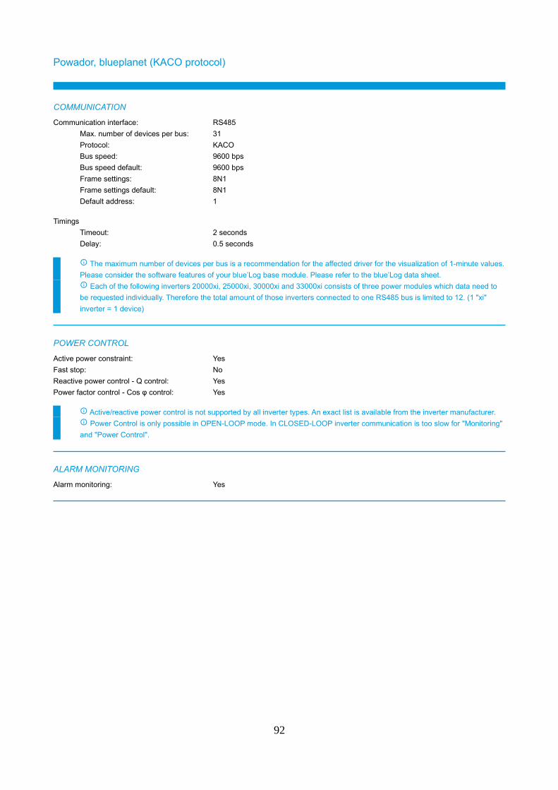
Powador, blueplanet (KACO protocol)
COMMUNICATION
Communication interface: RS485
Max. number of devices per bus: 31
Protocol: KACO
Bus speed: 9600 bps
Bus speed default: 9600 bps
Frame settings: 8N1
Frame settings default: 8N1
Default address: 1
Timings
Timeout: 2 seconds
Delay: 0.5 seconds
The maximum number of devices per bus is a recommendation for the affected driver for the visualization of 1-minute values.
Please consider the software features of your blue’Log base module. Please refer to the blue’Log data sheet.
Each of the following inverters 20000xi, 25000xi, 30000xi and 33000xi consists of three power modules which data need to
be requested individually. Therefore the total amount of those inverters connected to one RS485 bus is limited to 12. (1 "xi"
inverter = 1 device)
POWER CONTROL
Active power constraint: Yes
Fast stop: No
Reactive power control - Q control: Yes
Power factor control - Cos φ control: Yes
Active/reactive power control is not supported by all inverter types. An exact list is available from the inverter manufacturer.
Power Control is only possible in OPEN-LOOP mode. In CLOSED-LOOP inverter communication is too slow for "Monitoring"
and "Power Control".
ALARM MONITORING
Alarm monitoring: Yes
92
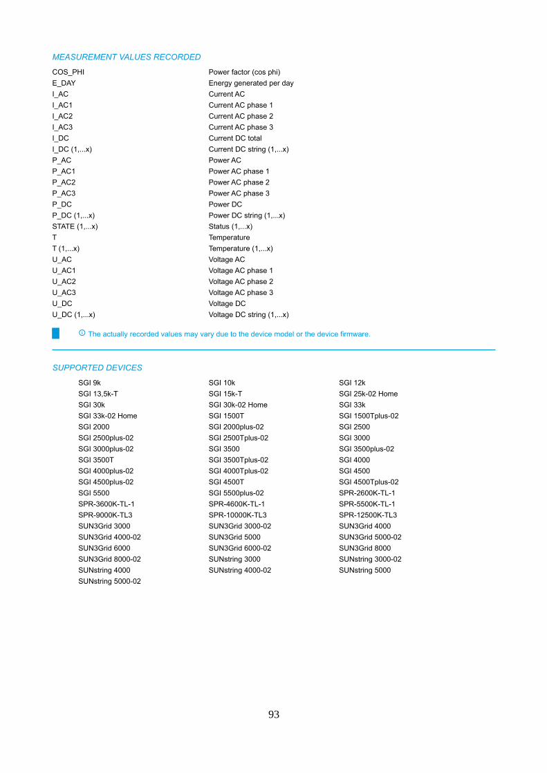
MEASUREMENT VALUES RECORDED
COS_PHI Power factor (cos phi)
E_DAY Energy generated per day
I_AC Current AC
I_AC1 Current AC phase 1
I_AC2 Current AC phase 2
I_AC3 Current AC phase 3
I_DC Current DC total
I_DC (1,...x) Current DC string (1,...x)
P_AC Power AC
P_AC1 Power AC phase 1
P_AC2 Power AC phase 2
P_AC3 Power AC phase 3
P_DC Power DC
P_DC (1,...x) Power DC string (1,...x)
STATE (1,...x) Status (1,...x)
T Temperature
T (1,...x) Temperature (1,...x)
U_AC Voltage AC
U_AC1 Voltage AC phase 1
U_AC2 Voltage AC phase 2
U_AC3 Voltage AC phase 3
U_DC Voltage DC
U_DC (1,...x) Voltage DC string (1,...x)
The actually recorded values may vary due to the device model or the device firmware.
SUPPORTED DEVICES
SGI 9k SGI 10k SGI 12k
SGI 13,5k-T SGI 15k-T SGI 25k-02 Home
SGI 30k SGI 30k-02 Home SGI 33k
SGI 33k-02 Home SGI 1500T SGI 1500Tplus-02
SGI 2000 SGI 2000plus-02 SGI 2500
SGI 2500plus-02 SGI 2500Tplus-02 SGI 3000
SGI 3000plus-02 SGI 3500 SGI 3500plus-02
SGI 3500T SGI 3500Tplus-02 SGI 4000
SGI 4000plus-02 SGI 4000Tplus-02 SGI 4500
SGI 4500plus-02 SGI 4500T SGI 4500Tplus-02
SGI 5500 SGI 5500plus-02 SPR-2600K-TL-1
SPR-3600K-TL-1 SPR-4600K-TL-1 SPR-5500K-TL-1
SPR-9000K-TL3 SPR-10000K-TL3 SPR-12500K-TL3
SUN3Grid 3000 SUN3Grid 3000-02 SUN3Grid 4000
SUN3Grid 4000-02 SUN3Grid 5000 SUN3Grid 5000-02
SUN3Grid 6000 SUN3Grid 6000-02 SUN3Grid 8000
SUN3Grid 8000-02 SUNstring 3000 SUNstring 3000-02
SUNstring 4000 SUNstring 4000-02 SUNstring 5000
SUNstring 5000-02
93
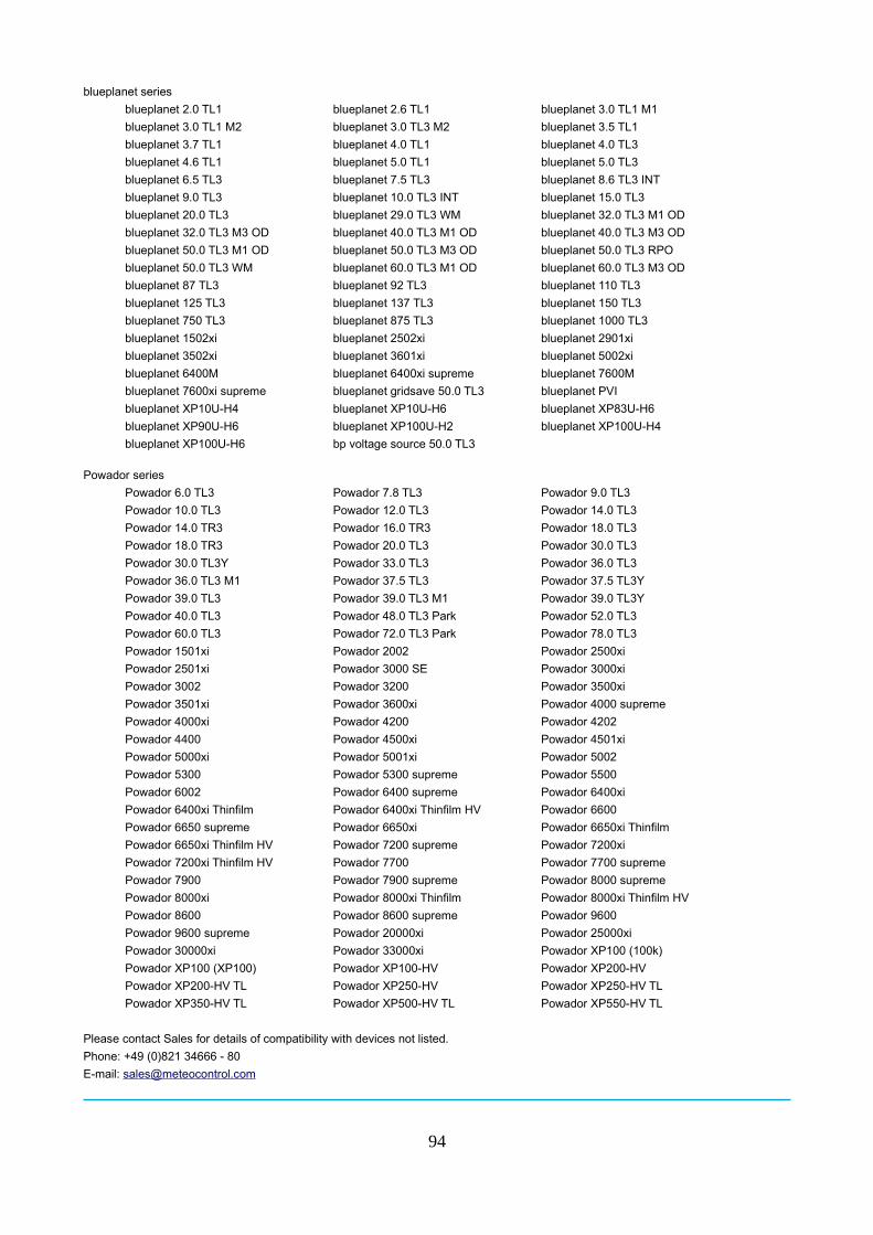
blueplanet series
blueplanet 2.0 TL1 blueplanet 2.6 TL1 blueplanet 3.0 TL1 M1
blueplanet 3.0 TL1 M2 blueplanet 3.0 TL3 M2 blueplanet 3.5 TL1
blueplanet 3.7 TL1 blueplanet 4.0 TL1 blueplanet 4.0 TL3
blueplanet 4.6 TL1 blueplanet 5.0 TL1 blueplanet 5.0 TL3
blueplanet 6.5 TL3 blueplanet 7.5 TL3 blueplanet 8.6 TL3 INT
blueplanet 9.0 TL3 blueplanet 10.0 TL3 INT blueplanet 15.0 TL3
blueplanet 20.0 TL3 blueplanet 29.0 TL3 WM blueplanet 32.0 TL3 M1 OD
blueplanet 32.0 TL3 M3 OD blueplanet 40.0 TL3 M1 OD blueplanet 40.0 TL3 M3 OD
blueplanet 50.0 TL3 M1 OD blueplanet 50.0 TL3 M3 OD blueplanet 50.0 TL3 RPO
blueplanet 50.0 TL3 WM blueplanet 60.0 TL3 M1 OD blueplanet 60.0 TL3 M3 OD
blueplanet 87 TL3 blueplanet 92 TL3 blueplanet 110 TL3
blueplanet 125 TL3 blueplanet 137 TL3 blueplanet 150 TL3
blueplanet 750 TL3 blueplanet 875 TL3 blueplanet 1000 TL3
blueplanet 1502xi blueplanet 2502xi blueplanet 2901xi
blueplanet 3502xi blueplanet 3601xi blueplanet 5002xi
blueplanet 6400M blueplanet 6400xi supreme blueplanet 7600M
blueplanet 7600xi supreme blueplanet gridsave 50.0 TL3 blueplanet PVI
blueplanet XP10U-H4 blueplanet XP10U-H6 blueplanet XP83U-H6
blueplanet XP90U-H6 blueplanet XP100U-H2 blueplanet XP100U-H4
blueplanet XP100U-H6 bp voltage source 50.0 TL3
Powador series
Powador 6.0 TL3 Powador 7.8 TL3 Powador 9.0 TL3
Powador 10.0 TL3 Powador 12.0 TL3 Powador 14.0 TL3
Powador 14.0 TR3 Powador 16.0 TR3 Powador 18.0 TL3
Powador 18.0 TR3 Powador 20.0 TL3 Powador 30.0 TL3
Powador 30.0 TL3Y Powador 33.0 TL3 Powador 36.0 TL3
Powador 36.0 TL3 M1 Powador 37.5 TL3 Powador 37.5 TL3Y
Powador 39.0 TL3 Powador 39.0 TL3 M1 Powador 39.0 TL3Y
Powador 40.0 TL3 Powador 48.0 TL3 Park Powador 52.0 TL3
Powador 60.0 TL3 Powador 72.0 TL3 Park Powador 78.0 TL3
Powador 1501xi Powador 2002 Powador 2500xi
Powador 2501xi Powador 3000 SE Powador 3000xi
Powador 3002 Powador 3200 Powador 3500xi
Powador 3501xi Powador 3600xi Powador 4000 supreme
Powador 4000xi Powador 4200 Powador 4202
Powador 4400 Powador 4500xi Powador 4501xi
Powador 5000xi Powador 5001xi Powador 5002
Powador 5300 Powador 5300 supreme Powador 5500
Powador 6002 Powador 6400 supreme Powador 6400xi
Powador 6400xi Thinfilm Powador 6400xi Thinfilm HV Powador 6600
Powador 6650 supreme Powador 6650xi Powador 6650xi Thinfilm
Powador 6650xi Thinfilm HV Powador 7200 supreme Powador 7200xi
Powador 7200xi Thinfilm HV Powador 7700 Powador 7700 supreme
Powador 7900 Powador 7900 supreme Powador 8000 supreme
Powador 8000xi Powador 8000xi Thinfilm Powador 8000xi Thinfilm HV
Powador 8600 Powador 8600 supreme Powador 9600
Powador 9600 supreme Powador 20000xi Powador 25000xi
Powador 30000xi Powador 33000xi Powador XP100 (100k)
Powador XP100 (XP100) Powador XP100-HV Powador XP200-HV
Powador XP200-HV TL Powador XP250-HV Powador XP250-HV TL
Powador XP350-HV TL Powador XP500-HV TL Powador XP550-HV TL
Please contact Sales for details of compatibility with devices not listed.
Phone: +49 (0)821 34666 - 80
E-mail: [email protected]
94
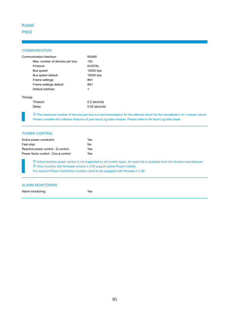
Kostal
PIKO
COMMUNICATION
Communication interface: RS485
Max. number of devices per bus: 100
Protocol: KOSTAL
Bus speed: 19200 bps
Bus speed default: 19200 bps
Frame settings: 8N1
Frame settings default: 8N1
Default address: 1
Timings
Timeout: 0.2 seconds
Delay: 0.05 seconds
The maximum number of devices per bus is a recommendation for the affected driver for the visualization of 1-minute values.
Please consider the software features of your blue’Log base module. Please refer to the blue’Log data sheet.
POWER CONTROL
Active power constraint: Yes
Fast stop: No
Reactive power control - Q control: Yes
Power factor control - Cos φ control: Yes
Active/reactive power control is not supported by all inverter types. An exact list is available from the inverter manufacturer.
Only inverters with firmware version ≥ 3.50 support active Power Control.
For reactive Power Control the inverters need to be equipped with firmware ≥ 3.90
ALARM MONITORING
Alarm monitoring: Yes
95
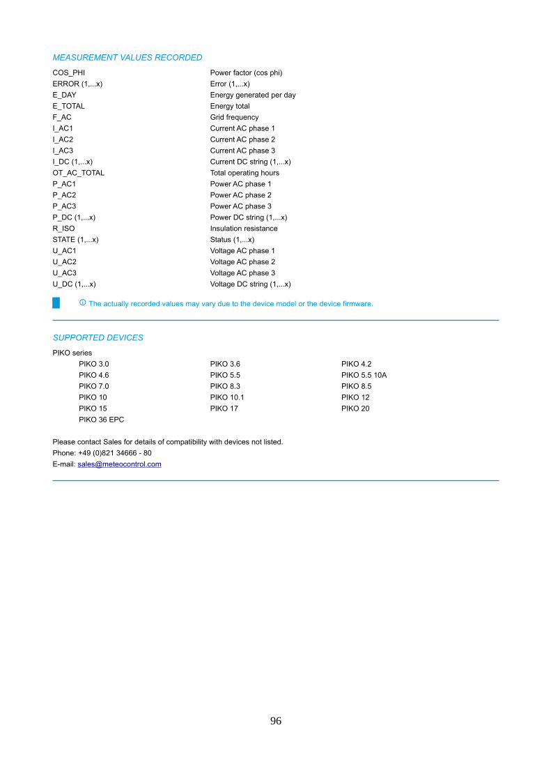
MEASUREMENT VALUES RECORDED
COS_PHI Power factor (cos phi)
ERROR (1,...x) Error (1,...x)
E_DAY Energy generated per day
E_TOTAL Energy total
F_AC Grid frequency
I_AC1 Current AC phase 1
I_AC2 Current AC phase 2
I_AC3 Current AC phase 3
I_DC (1,...x) Current DC string (1,...x)
OT_AC_TOTAL Total operating hours
P_AC1 Power AC phase 1
P_AC2 Power AC phase 2
P_AC3 Power AC phase 3
P_DC (1,...x) Power DC string (1,...x)
R_ISO Insulation resistance
STATE (1,...x) Status (1,...x)
U_AC1 Voltage AC phase 1
U_AC2 Voltage AC phase 2
U_AC3 Voltage AC phase 3
U_DC (1,...x) Voltage DC string (1,...x)
The actually recorded values may vary due to the device model or the device firmware.
SUPPORTED DEVICES
PIKO series
PIKO 3.0 PIKO 3.6 PIKO 4.2
PIKO 4.6 PIKO 5.5 PIKO 5.5 10A
PIKO 7.0 PIKO 8.3 PIKO 8.5
PIKO 10 PIKO 10.1 PIKO 12
PIKO 15 PIKO 17 PIKO 20
PIKO 36 EPC
Please contact Sales for details of compatibility with devices not listed.
Phone: +49 (0)821 34666 - 80
E-mail: [email protected]
96
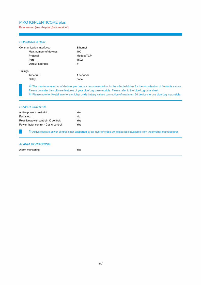
PIKO IQ/PLENTICORE plusBeta version (see chapter „Beta version“)
COMMUNICATION
Communication interface: Ethernet
Max. number of devices: 100
Protocol: ModbusTCP
Port: 1502
Default address: 71
Timings
Timeout: 1 seconds
Delay: none
The maximum number of devices per bus is a recommendation for the affected driver for the visualization of 1-minute values.
Please consider the software features of your blue’Log base module. Please refer to the blue’Log data sheet.
Please note for Kostal inverters which provide battery values connection of maximum 50 devices to one blue'Log is possible.
POWER CONTROL
Active power constraint: Yes
Fast stop: No
Reactive power control - Q control: Yes
Power factor control - Cos φ control: Yes
Active/reactive power control is not supported by all inverter types. An exact list is available from the inverter manufacturer.
ALARM MONITORING
Alarm monitoring: Yes
97
MEASUREMENT VALUES RECORDED
B_CAPACITY Nominal capacity
B_CHARGE_LEVEL Charging status
B_P_DC Battery power
B_U_DC Battery voltage
COS_PHI Power factor (cos phi)
E_DAY Energy generated per day
E_TOTAL Energy total
F_AC Grid frequency
I_AC1 Current AC phase 1
I_AC2 Current AC phase 2
I_AC3 Current AC phase 3
I_DC (1,...x) Current DC string (1,...x)
OT_AC_TOTAL Total operating hours
P_AC Power AC
P_AC1 Power AC phase 1
P_AC2 Power AC phase 2
P_AC3 Power AC phase 3
P_DC Power DC
P_DC (1,...x) Power DC string (1,...x)
Q_AC Reactive power
R_ISO Insulation resistance
STATE (1,...x) Status (1,...x)
S_AC Apparent power
T Temperature
U_AC1 Voltage AC phase 1
U_AC2 Voltage AC phase 2
U_AC3 Voltage AC phase 3
U_DC (1,...x) Voltage DC string (1,...x)
The actually recorded values may vary due to the device model or the device firmware.
SUPPORTED DEVICES
PIKO IQ series
PIKO IQ 4.2 PIKO IQ 5.5 PIKO IQ 7.0
PIKO IQ 8.5 PIKO IQ 10
PLENTICORE plus series
PLENTICORE plus 4.2 PLENTICORE plus 5.5 PLENTICORE plus 7.0
PLENTICORE plus 8.5 PLENTICORE plus 10
Please contact Sales for details of compatibility with devices not listed.
Phone: +49 (0)821 34666 - 80
E-mail: [email protected]
98
Kstar
KSG1K-60K
COMMUNICATION
Communication interface: RS485
Max. number of devices per bus: 32
Protocol: ModbusRTU
Bus speed: 2400 bps, 4800 bps, 9600 bps
Bus speed default: 9600 bps
Frame settings: 8N1
Frame settings default: 8N1
Default address: 1
Timings
Timeout: 1 seconds
Delay: none
The maximum number of devices per bus is a recommendation for the affected driver for the visualization of 1-minute values.
Please consider the software features of your blue’Log base module. Please refer to the blue’Log data sheet.
The driver supports the address range 1 to 32. The address 0 does not get supported.
The maximum number of 32 devices can get connected to one bus interface.
POWER CONTROL
Active power constraint: Yes
Fast stop: Yes
Reactive power control - Q control: Yes
Power factor control - Cos φ control: Yes
Active/reactive power control is not supported by all inverter types. An exact list is available from the inverter manufacturer.
ALARM MONITORING
Alarm monitoring: Yes
99
MEASUREMENT VALUES RECORDED
COS_PHI Power factor (cos phi)
ERROR (1,...x) Error (1,...x)
E_DAY Energy generated per day
E_TOTAL Energy total
F_AC Grid frequency
F_AC1 Grid frequency phase 1
F_AC2 Grid frequency phase 2
F_AC3 Grid frequency phase 3
I_AC Current AC
I_AC1 Current AC phase 1
I_AC2 Current AC phase 2
I_AC3 Current AC phase 3
I_DC Current DC total
I_DC (1,...x) Current DC string (1,...x)
P_AC Power AC
P_DC Power DC
P_DC (1,...x) Power DC string (1,...x)
Q_AC Reactive power
R_ISO Insulation resistance
STATE (1,...x) Status (1,...x)
S_AC Apparent power
T (1,...x) Temperature (1,...x)
U_AC Voltage AC
U_AC_L1L2 Phase voltage L1L2
U_AC_L2L3 Phase voltage L2L3
U_AC_L3L1 Phase voltage L3L1
U_DC Voltage DC
U_DC (1,...x) Voltage DC string (1,...x)
U_DC_NE Voltage DC negative pole to earth
U_DC_PE Voltage DC positive pole to earth
The actually recorded values may vary due to the device model or the device firmware.
SUPPORTED DEVICES
KSG1.5KSM3 KSG1KSM3 KSG2KSM3
KSG3.2KDM3 KSG3KSM3 KSG4KDM3
KSG5KDM3 KSG6KDM3/KSG10K KSG12.5K
KSG15K KSG17K KSG20K
KSG25KHV KSG30K KSG36KHV
KSG40K KSG50K KSG50KHV
KSG60K KSG60KHV
Please contact Sales for details of compatibility with devices not listed.
Phone: +49 (0)821 34666 - 80
E-mail: [email protected]
100
LTi ReEnergy
PVMaster II/III
COMMUNICATION
Communication interface: Ethernet
Max. number of devices: 100
Protocol: ModbusTCP
Port: 502
Default address: 1
Timings
Timeout: 1 seconds
Delay: 0.1 seconds
The maximum number of devices per bus is a recommendation for the affected driver for the visualization of 1-minute values.
Please consider the software features of your blue’Log base module. Please refer to the blue’Log data sheet.
Up to 10 LTi String Combiner Boxes can get connected to a PVMaster II/ III inverter.
Depending on the amount of String Combiner Boxes connected the total amount of devices varies that can be connected to one
blue’Log (e.g. 1 x PVMaster II/ III with 10 LTi String Combiner Boxes = 11 devices).
POWER CONTROL
Active power constraint: Yes
Fast stop: No
Reactive power control - Q control: No
Power factor control - Cos φ control: Yes
Active/reactive power control is not supported by all inverter types. An exact list is available from the inverter manufacturer.
ALARM MONITORING
Alarm monitoring: Yes
101

MEASUREMENT VALUES RECORDED
COS_PHI Power factor (cos phi)
COS_PHI1 Power factor (cos phi) phase 1
COS_PHI2 Power factor (cos phi) phase 2
COS_PHI3 Power factor (cos phi) phase 3
ERROR (1,...x) Error (1,...x)
E_DAY Energy generated per day
E_TOTAL Energy total
F_AC Grid frequency
I (1,...x) Current DC (1,...x)
I_AC1 Current AC phase 1
I_AC2 Current AC phase 2
I_AC3 Current AC phase 3
I_DC Current DC total
OT_AC_TOTAL Total operating hours
P_AC Power AC
P_AC1 Power AC phase 1
P_AC2 Power AC phase 2
P_AC3 Power AC phase 3
P_DC Power DC
Q_AC Reactive power
Q_AC1 Reactive power phase 1
Q_AC2 Reactive power phase 2
Q_AC3 Reactive power phase 3
R_ISO Insulation resistance
STATE (1,...x) Status (1,...x)
S_AC Apparent power
S_AC1 Apparent power phase 1
S_AC2 Apparent power phase 2
S_AC3 Apparent power phase 3
T Temperature
T (1,...x) Temperature (1,...x)
U_AC1 Voltage AC phase 1
U_AC2 Voltage AC phase 2
U_AC3 Voltage AC phase 3
U_AC_L1L2 Phase voltage L1L2
U_AC_L2L3 Phase voltage L2L3
U_AC_L3L1 Phase voltage L3L1
U_DC Voltage DC
The actually recorded values may vary due to the device model or the device firmware.
SUPPORTED DEVICES
LTi String Combiner Boxes PVMaster II PVMaster III
Please contact Sales for details of compatibility with devices not listed.
Phone: +49 (0)821 34666 - 80
E-mail: [email protected]
102
Power Electronics
HE / HEC / HES Series
COMMUNICATION
Communication interface: Ethernet
Max. number of devices: 100
Protocol: ModbusTCP
Port: 502
Default address: 1
Communication interface: RS485
Max. number of devices per bus: 58
Protocol: ModbusRTU
Bus speed: 600 bps, 1200 bps, 2400 bps, 4800 bps, 9600 bps, 19200 bps
Bus speed default: 9600 bps
Frame settings: 8N1
Frame settings default: 8N1
Default address: 10
Timings
Timeout: 5 seconds
Delay: none
The maximum number of devices per bus is a recommendation for the affected driver for the visualization of 1-minute values.
Please consider the software features of your blue’Log base module. Please refer to the blue’Log data sheet.
In case SKID modules from Power Electronics should be connected to the inverters it is necessary to scan the SKID modules
separately by using the SKID sensor driver.
Power Electronics inverters from the series HEM, HEMK consist of several inverter modules (up to 10) and string combiner
(1 per inverter).
Depending on the combination of modules and string combiners the total amount of devices varies that can be connected to one
blue’Log (e.g. 1 Power Electronics inverter with 6 inverter modules + 1 string combiner = 8 devices).
POWER CONTROL
Active power constraint: Yes
Fast stop: No
Reactive power control - Q control: Yes
Power factor control - Cos φ control: Yes
Active/reactive power control is not supported by all inverter types. An exact list is available from the inverter manufacturer.
ALARM MONITORING
Alarm monitoring: Yes
103
MEASUREMENT VALUES RECORDED
COS_PHI Power factor (cos phi)
E_TOTAL Energy total
F_AC Grid frequency
I_AC1 Current AC phase 1
I_AC2 Current AC phase 2
I_AC3 Current AC phase 3
I_DC Current DC total
OT_AC_TOTAL Total operating hours
P_AC Power AC
P_DC Power DC
STATE (1,...x) Status (1,...x)
T Temperature
U_AC Voltage AC
U_AC1 Voltage AC phase 1
U_AC2 Voltage AC phase 2
U_AC3 Voltage AC phase 3
U_DC Voltage DC
The actually recorded values may vary due to the device model or the device firmware.
The driver does not support Measurement values of the "String Supervisor" from Power Electronics.
SUPPORTED DEVICES
HE series
FS0200IH FS0230IH FS0250IH
FS0280IH FS0300IH FS0340IH
FS0380IH FS0400IH FS0420IH
FS0460IH FS0500IH FS0501IH
FS0560IH FS0570IH FS0600IH
FS0630IH FS0680IH FS0700IH
FS0701IH FS0750IH FS0800IH
FS0801IH FS0830IH FS0880IH
FS0900IH FS0910IH FS0970IH
FS1000IH FS1001IH FS1030IH
FS1110IH FS1130IH FS1140IH
FS1250IH FS1251IH FS1390IH
HECplus series
FS1003CH FS1051CH FS1112CH
FS1162CH FS1201CH FS1271CH
FS1331CH FS1391CH FS1401CH
FS1480CH FS1550CH FS1600CH
FS1620CH FS1690CH FS1770CH
FS1800CH FS1850CH FS1901CH
FS1991CH FS2000CH FS2081CH
FS2110CH FS2200CH FS2300CH
Please contact Sales for details of compatibility with devices not listed.
Phone: +49 (0)821 34666 - 80
E-mail: [email protected]
104
HEM seriesBeta version (see chapter „Beta version“)
COMMUNICATION
Communication interface: Ethernet
Max. number of devices: 100
Protocol: ModbusTCP
Port: 502
Default address: 1
Communication interface: RS485
Max. number of devices per bus: 39
Protocol: ModbusRTU
Bus speed: 9600 bps, 19200 bps, 57600 bps, 115200 bps
Bus speed default: 9600 bps
Frame settings: 8N1, 8O1, 8E1, 8N2, 8O2, 8E2
Frame settings default: 8N1
Default address: 1
Timings
Timeout: 1 seconds
Delay: none
The maximum number of devices per bus is a recommendation for the affected driver for the visualization of 1-minute values.
Please consider the software features of your blue’Log base module. Please refer to the blue’Log data sheet.
Power Electronics inverters from the series HEM, HEMK consist of several inverter modules (up to 10) and string combiner
(1 per inverter).
Depending on the combination of modules and string combiners the total amount of devices varies that can be connected to one
blue’Log (e.g. 1 Power Electronics inverter with 6 inverter modules + 1 string combiner = 8 devices).
For a successful scan the inverter needs to be configured to one of the following operation modes: Standard, Modular or HEM.
The operation mode STATCOM does not get supported.
POWER CONTROL
Active power constraint: Yes
Fast stop: Yes
Reactive power control - Q control: Yes
Power factor control - Cos φ control: Yes
Active/reactive power control is not supported by all inverter types. An exact list is available from the inverter manufacturer.
ALARM MONITORING
Alarm monitoring: Yes
105
MEASUREMENT VALUES RECORDED
COS_PHI Power factor (cos phi)
ERROR (1,...x) Error (1,...x)
E_DAY Energy generated per day
E_TOTAL Energy total
F_AC Grid frequency
I_AC1 Current AC phase 1
I_AC2 Current AC phase 2
I_AC3 Current AC phase 3
I_DC Current DC total
OT_AC_TOTAL Total operating hours
P_AC Power AC
P_DC Power DC
Q_AC Reactive power
R_ISO Insulation resistance
STATE (1,...x) Status (1,...x)
S_AC Apparent power
T (1,...x) Temperature (1,...x)
U_AC_L1L2 Phase voltage L1L2
U_AC_L2L3 Phase voltage L2L3
U_AC_L3L1 Phase voltage L3L1
U_DC Voltage DC
The actually recorded values may vary due to the device model or the device firmware.
SUPPORTED DEVICES
HEM series series
FS3190M FS3270M FS3350M
FS3430M FS3510M
Please contact Sales for details of compatibility with devices not listed.
Phone: +49 (0)821 34666 - 80
E-mail: [email protected]
106
HEMK seriesBeta version (see chapter „Beta version“)
COMMUNICATION
Communication interface: Ethernet
Max. number of devices: 100
Protocol: ModbusTCP
Port: 502
Default address: 1
Communication interface: RS485
Max. number of devices per bus: 50
Protocol: ModbusRTU
Bus speed: 9600 bps, 19200 bps, 57600 bps, 115200 bps
Bus speed default: 9600 bps
Frame settings: 8N1, 8O1, 8E1, 8N2, 8O2, 8E2
Frame settings default: 8N1
Default address: 1
Timings
Timeout: 1 seconds
Delay: none
The maximum number of devices per bus is a recommendation for the affected driver for the visualization of 1-minute values.
Please consider the software features of your blue’Log base module. Please refer to the blue’Log data sheet.
Power Electronics inverters from the series HEM, HEMK consist of several inverter modules (up to 10) and string combiner
(1 per inverter).
Depending on the combination of modules and string combiners the total amount of devices varies that can be connected to one
blue’Log (e.g. 1 Power Electronics inverter with 6 inverter modules + 1 string combiner = 8 devices).
For a successful scan the inverter needs to be configured to one of the following operation modes: Standard, Modular or HEM.
The operation mode STATCOM does not get supported.
POWER CONTROL
Active power constraint: Yes
Fast stop: Yes
Reactive power control - Q control: Yes
Power factor control - Cos φ control: Yes
Active/reactive power control is not supported by all inverter types. An exact list is available from the inverter manufacturer.
ALARM MONITORING
Alarm monitoring: Yes
107
MEASUREMENT VALUES RECORDED
COS_PHI Power factor (cos phi)
ERROR (1,...x) Error (1,...x)
E_DAY Energy generated per day
E_TOTAL Energy total
F_AC Grid frequency
I_AC1 Current AC phase 1
I_AC2 Current AC phase 2
I_AC3 Current AC phase 3
I_DC Current DC total
OT_AC_TOTAL Total operating hours
P_AC Power AC
P_DC Power DC
Q_AC Reactive power
R_ISO Insulation resistance
STATE (1,...x) Status (1,...x)
S_AC Apparent power
T (1,...x) Temperature (1,...x)
U_AC_L1L2 Phase voltage L1L2
U_AC_L2L3 Phase voltage L2L3
U_AC_L3L1 Phase voltage L3L1
U_DC Voltage DC
The actually recorded values may vary due to the device model or the device firmware.
SUPPORTED DEVICES
HEMK series series
FS2000K FS2050K FS2100K
FS2125K FS2150K FS2180K
FS2200K FS2235K FS2285K
FS2300K FS2340K FS2445K
FS3000K FS3075K FS3150K
FS3190K FS3225K FS3270K
FS3300K FS3350K FS3430K
FS3450K FS3510K FS3670K
Please contact Sales for details of compatibility with devices not listed.
Phone: +49 (0)821 34666 - 80
E-mail: [email protected]
108
REFU / Siemens / Schueco / LSIS / Satcon / Advanced Energy
REFUsol, AE 3TL (USS Protocol)
COMMUNICATION
Communication interface: Ethernet
Max. number of devices: 31
Protocol: USS_ETHERNET
Port: 21062
Default address: 0
Communication interface: RS485
Max. number of devices per bus: 31
Protocol: USS_SERIAL
Bus speed: 9600 bps, 19200 bps, 57600 bps, 115200 bps
Bus speed default: 57600 bps
Frame settings: 8E1, 8N1
Frame settings default: 8E1
Default address: 0
Timings
Timeout: 0.5 seconds
Delay: none
The maximum number of devices per bus is a recommendation for the affected driver for the visualization of 1-minute values.
Please consider the software features of your blue’Log base module. Please refer to the blue’Log data sheet.
If meteocontrol protocol is selected in the inverter settings, 8N1 (Data bits 8 bits / Parity None / Stop bit 1 bit) must be
selected as frame settings for successful scanning.
POWER CONTROL
Active power constraint: Yes
Fast stop: No
Reactive power control - Q control: Yes
Power factor control - Cos φ control: Yes
Active/reactive power control is not supported by all inverter types. An exact list is available from the inverter manufacturer.
Only inverters with software version ≥ 29.21 are supporting Power Control.
ALARM MONITORING
Alarm monitoring: Yes
109
MEASUREMENT VALUES RECORDED
ERROR (1,...x) Error (1,...x)
E_DAY Energy generated per day
E_TOTAL Energy total
F_AC1 Grid frequency phase 1
F_AC2 Grid frequency phase 2
F_AC3 Grid frequency phase 3
I_AC1 Current AC phase 1
I_AC2 Current AC phase 2
I_AC3 Current AC phase 3
I_DC Current DC total
OT_AC_TOTAL Total operating hours
P_AC Power AC
P_DC Power DC
R_ISO Insulation resistance
STATE (1,...x) Status (1,...x)
T (1,...x) Temperature (1,...x)
U_AC1 Voltage AC phase 1
U_AC2 Voltage AC phase 2
U_AC3 Voltage AC phase 3
U_DC Voltage DC
The actually recorded values may vary due to the device model or the device firmware.
SUPPORTED DEVICES
AE 3TL series
AE 3TL 8-IEC (CPV Gen 3) AE 3TL 8-IEC (Gen 3) AE 3TL 10-IEC (CPV Gen 3)
AE 3TL 10-IEC (Gen 3) AE 3TL 10-KR AE 3TL 12-UL (500V AFCI Gen 2)
AE 3TL 12-UL (500V Gen 2) AE 3TL 12-UL (500V Gen 3) AE 3TL 12-UL (1000V AFCI Gen 2)
AE 3TL 12-UL (1000V Gen 2) AE 3TL 12-UL (1000V Gen 3) AE 3TL 13-IEC (CPV Gen 2)
AE 3TL 13-IEC (CPV Gen 3) AE 3TL 13-IEC (Gen 2) AE 3TL 13-IEC (Gen 3)
AE 3TL 13-KR AE 3TL 16-UL (500V AFCI Gen 2) AE 3TL 16-UL (500V Gen 2)
AE 3TL 16-UL (500V Gen 3) AE 3TL 16-UL (1000V AFCI Gen 2) AE 3TL 16-UL (1000V Gen 2)
AE 3TL 16-UL (1000V Gen 3) AE 3TL 17-IEC (CPV Gen 2) AE 3TL 17-IEC (CPV Gen 3)
AE 3TL 17-IEC (Gen 2) AE 3TL 17-IEC (Gen 3) AE 3TL 17-KR
AE 3TL 20-IEC (CPV Gen 2) AE 3TL 20-IEC (CPV Gen 3) AE 3TL 20-IEC (Gen 2)
AE 3TL 20-IEC (Gen 3) AE 3TL 20-KR AE 3TL 20-UL (500V AFCI Gen 2)
AE 3TL 20-UL (500V Gen 2) AE 3TL 20-UL (500V Gen 3) AE 3TL 20-UL (1000V AFCI Gen 2)
AE 3TL 20-UL (1000V Gen 2) AE 3TL 20-UL (1000V Gen 3) AE 3TL 23-IEC (Gen 2)
AE 3TL 23-IEC (MV Gen 3) AE 3TL 23-KR (MV) AE 3TL 23-UL (500V AFCI Gen 2)
AE 3TL 23-UL (500V Gen 2) AE 3TL 23-UL (500V Gen 3) AE 3TL 23-UL (1000V AFCI Gen 2)
AE 3TL 23-UL (1000V Gen 2) AE 3TL 23-UL (1000V Gen 3) AE 3TL 24-JP (1000V)
AE 3TL 24-UL (1000V Gen 3) AE 3TL 40-IEC AE 3TL 40-KR
AE 3TL 46-IEC (MV) AE 3TL 46-KR (MV)
Equinox LC series
Equinox LC CE 8kw Equinox LC CE 10kw Equinox LC CE 13kw
Equinox LC CE 17kw Equinox LC CE 20kw Equinox LC UL 12kw
Equinox LC UL 16kw Equinox LC UL 20kw Equinox LC UL 24kw
IPE series
IPE 010 CN 04 IPE 013 CN 04 IPE 017 CN 04
IPE 020 CN 04 IPE 8000 SN 04 SN 04
LSRP series
LSRP-T010L LSRP-T013L LSRP-T017L
LSRP-T020L
110
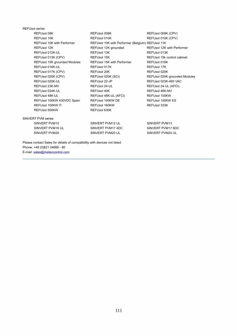
REFUsol series
REFUsol 08K REFUsol 008K REFUsol 008K (CPV)
REFUsol 10K REFUsol 010K REFUsol 010K (CPV)
REFUsol 10K with Performer REFUsol 10K with Performer (Belgium) REFUsol 11K
REFUsol 12K REFUsol 12K grounded REFUsol 12K with Performer
REFUsol 012K-UL REFUsol 13K REFUsol 013K
REFUsol 013K (CPV) REFUsol 15K REFUsol 15k control cabinet
REFUsol 15K grounded Modules REFUsol 15K with Performer REFUsol 016K
REFUsol 016K-UL REFUsol 017K REFUsol 17K
REFUsol 017K (CPV) REFUsol 20K REFUsol 020K
REFUsol 020K (CPV) REFUsol 020K (SCI) REFUsol 020K grounded Modules
REFUsol 020K-UL REFUsol 22-JP REFUsol 023K-460 VAC
REFUsol 23K-MV REFUsol 24-UL REFUsol 24-UL (AFCI)
REFUsol 024K-UL REFUsol 40K REFUsol 46K-MV
REFUsol 48K-UL REFUsol 48K-UL (AFCI) REFUsol 100KW
REFUsol 100KW 430VDC Spain REFUsol 100KW DE REFUsol 100KW ES
REFUsol 100KW IT REFUsol 160KW REFUsol 333K
REFUsol 500KW REFUsol 630K
SINVERT PVM series
SINVERT PVM10 SINVERT PVM12 UL SINVERT PVM13
SINVERT PVM16 UL SINVERT PVM17 4DC SINVERT PVM17 6DC
SINVERT PVM20 SINVERT PVM20 UL SINVERT PVM24 UL
Please contact Sales for details of compatibility with devices not listed.
Phone: +49 (0)821 34666 - 80
E-mail: [email protected]
111
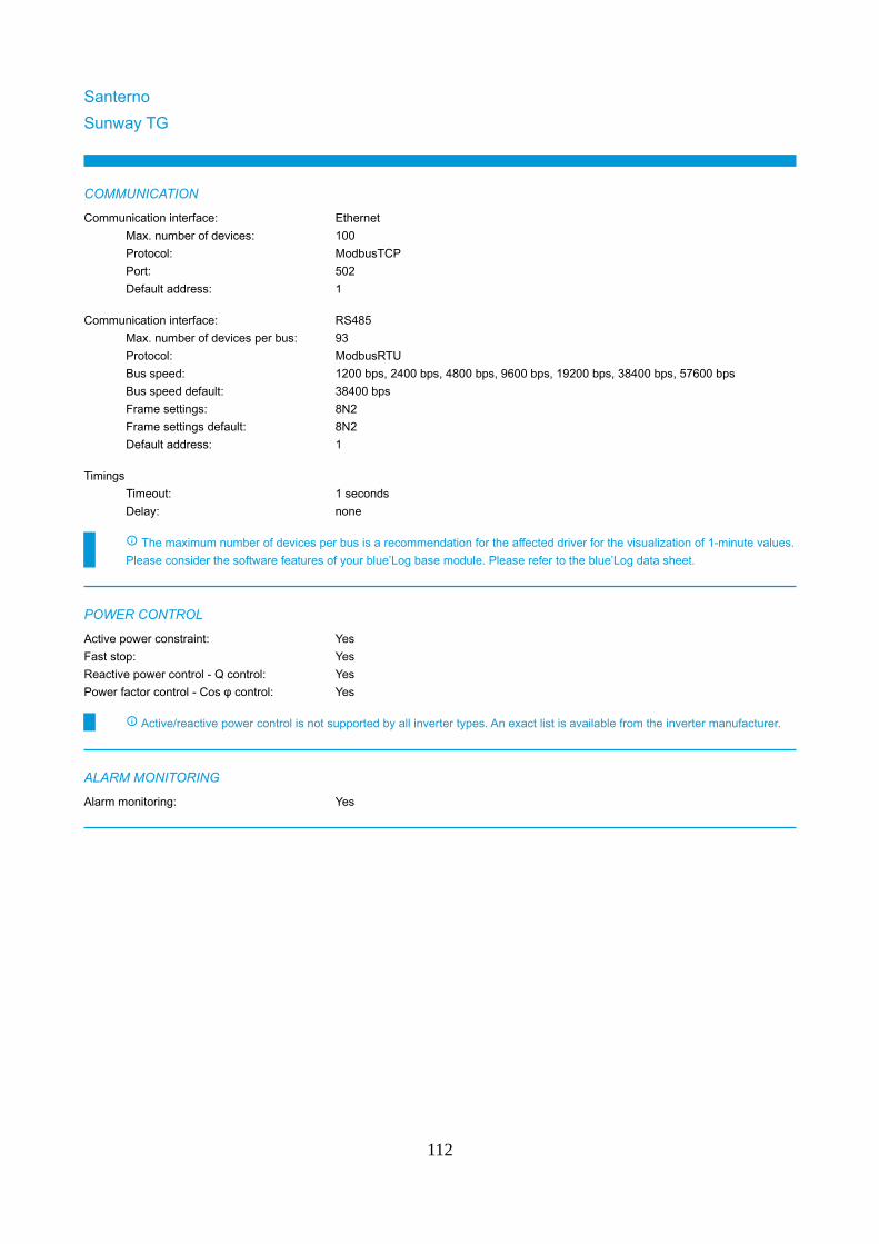
Santerno
Sunway TG
COMMUNICATION
Communication interface: Ethernet
Max. number of devices: 100
Protocol: ModbusTCP
Port: 502
Default address: 1
Communication interface: RS485
Max. number of devices per bus: 93
Protocol: ModbusRTU
Bus speed: 1200 bps, 2400 bps, 4800 bps, 9600 bps, 19200 bps, 38400 bps, 57600 bps
Bus speed default: 38400 bps
Frame settings: 8N2
Frame settings default: 8N2
Default address: 1
Timings
Timeout: 1 seconds
Delay: none
The maximum number of devices per bus is a recommendation for the affected driver for the visualization of 1-minute values.
Please consider the software features of your blue’Log base module. Please refer to the blue’Log data sheet.
POWER CONTROL
Active power constraint: Yes
Fast stop: Yes
Reactive power control - Q control: Yes
Power factor control - Cos φ control: Yes
Active/reactive power control is not supported by all inverter types. An exact list is available from the inverter manufacturer.
ALARM MONITORING
Alarm monitoring: Yes
112
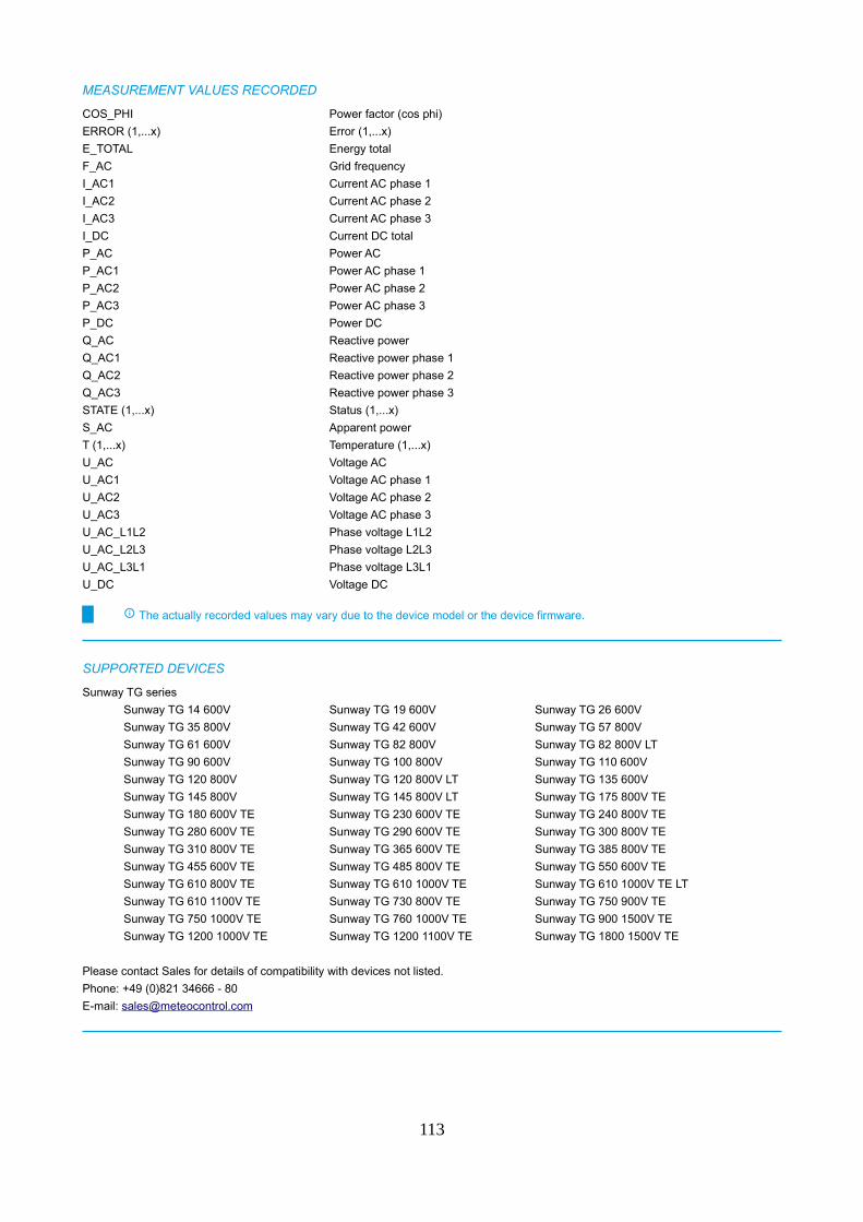
MEASUREMENT VALUES RECORDED
COS_PHI Power factor (cos phi)
ERROR (1,...x) Error (1,...x)
E_TOTAL Energy total
F_AC Grid frequency
I_AC1 Current AC phase 1
I_AC2 Current AC phase 2
I_AC3 Current AC phase 3
I_DC Current DC total
P_AC Power AC
P_AC1 Power AC phase 1
P_AC2 Power AC phase 2
P_AC3 Power AC phase 3
P_DC Power DC
Q_AC Reactive power
Q_AC1 Reactive power phase 1
Q_AC2 Reactive power phase 2
Q_AC3 Reactive power phase 3
STATE (1,...x) Status (1,...x)
S_AC Apparent power
T (1,...x) Temperature (1,...x)
U_AC Voltage AC
U_AC1 Voltage AC phase 1
U_AC2 Voltage AC phase 2
U_AC3 Voltage AC phase 3
U_AC_L1L2 Phase voltage L1L2
U_AC_L2L3 Phase voltage L2L3
U_AC_L3L1 Phase voltage L3L1
U_DC Voltage DC
The actually recorded values may vary due to the device model or the device firmware.
SUPPORTED DEVICES
Sunway TG series
Sunway TG 14 600V Sunway TG 19 600V Sunway TG 26 600V
Sunway TG 35 800V Sunway TG 42 600V Sunway TG 57 800V
Sunway TG 61 600V Sunway TG 82 800V Sunway TG 82 800V LT
Sunway TG 90 600V Sunway TG 100 800V Sunway TG 110 600V
Sunway TG 120 800V Sunway TG 120 800V LT Sunway TG 135 600V
Sunway TG 145 800V Sunway TG 145 800V LT Sunway TG 175 800V TE
Sunway TG 180 600V TE Sunway TG 230 600V TE Sunway TG 240 800V TE
Sunway TG 280 600V TE Sunway TG 290 600V TE Sunway TG 300 800V TE
Sunway TG 310 800V TE Sunway TG 365 600V TE Sunway TG 385 800V TE
Sunway TG 455 600V TE Sunway TG 485 800V TE Sunway TG 550 600V TE
Sunway TG 610 800V TE Sunway TG 610 1000V TE Sunway TG 610 1000V TE LT
Sunway TG 610 1100V TE Sunway TG 730 800V TE Sunway TG 750 900V TE
Sunway TG 750 1000V TE Sunway TG 760 1000V TE Sunway TG 900 1500V TE
Sunway TG 1200 1000V TE Sunway TG 1200 1100V TE Sunway TG 1800 1500V TE
Please contact Sales for details of compatibility with devices not listed.
Phone: +49 (0)821 34666 - 80
E-mail: [email protected]
113
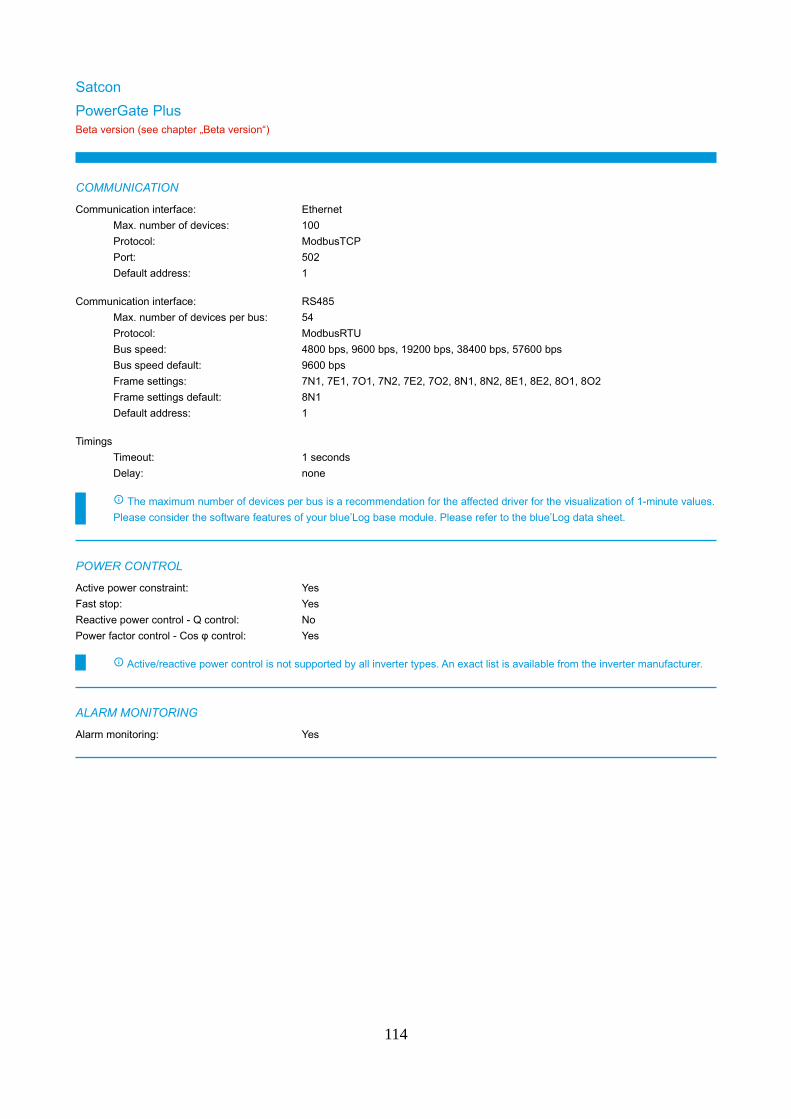
Satcon
PowerGate PlusBeta version (see chapter „Beta version“)
COMMUNICATION
Communication interface: Ethernet
Max. number of devices: 100
Protocol: ModbusTCP
Port: 502
Default address: 1
Communication interface: RS485
Max. number of devices per bus: 54
Protocol: ModbusRTU
Bus speed: 4800 bps, 9600 bps, 19200 bps, 38400 bps, 57600 bps
Bus speed default: 9600 bps
Frame settings: 7N1, 7E1, 7O1, 7N2, 7E2, 7O2, 8N1, 8N2, 8E1, 8E2, 8O1, 8O2
Frame settings default: 8N1
Default address: 1
Timings
Timeout: 1 seconds
Delay: none
The maximum number of devices per bus is a recommendation for the affected driver for the visualization of 1-minute values.
Please consider the software features of your blue’Log base module. Please refer to the blue’Log data sheet.
POWER CONTROL
Active power constraint: Yes
Fast stop: Yes
Reactive power control - Q control: No
Power factor control - Cos φ control: Yes
Active/reactive power control is not supported by all inverter types. An exact list is available from the inverter manufacturer.
ALARM MONITORING
Alarm monitoring: Yes
114
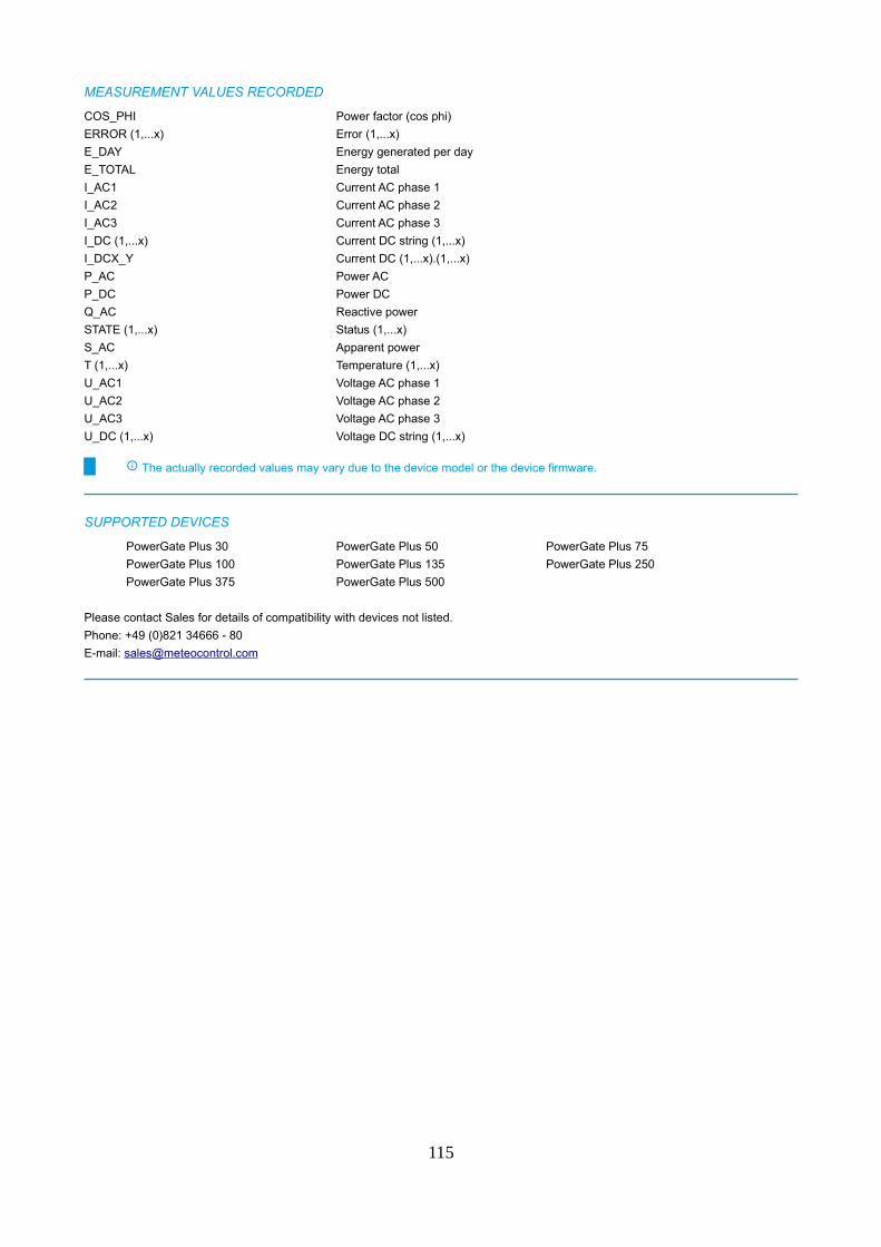
MEASUREMENT VALUES RECORDED
COS_PHI Power factor (cos phi)
ERROR (1,...x) Error (1,...x)
E_DAY Energy generated per day
E_TOTAL Energy total
I_AC1 Current AC phase 1
I_AC2 Current AC phase 2
I_AC3 Current AC phase 3
I_DC (1,...x) Current DC string (1,...x)
I_DCX_Y Current DC (1,...x).(1,...x)
P_AC Power AC
P_DC Power DC
Q_AC Reactive power
STATE (1,...x) Status (1,...x)
S_AC Apparent power
T (1,...x) Temperature (1,...x)
U_AC1 Voltage AC phase 1
U_AC2 Voltage AC phase 2
U_AC3 Voltage AC phase 3
U_DC (1,...x) Voltage DC string (1,...x)
The actually recorded values may vary due to the device model or the device firmware.
SUPPORTED DEVICES
PowerGate Plus 30 PowerGate Plus 50 PowerGate Plus 75
PowerGate Plus 100 PowerGate Plus 135 PowerGate Plus 250
PowerGate Plus 375 PowerGate Plus 500
Please contact Sales for details of compatibility with devices not listed.
Phone: +49 (0)821 34666 - 80
E-mail: [email protected]
115
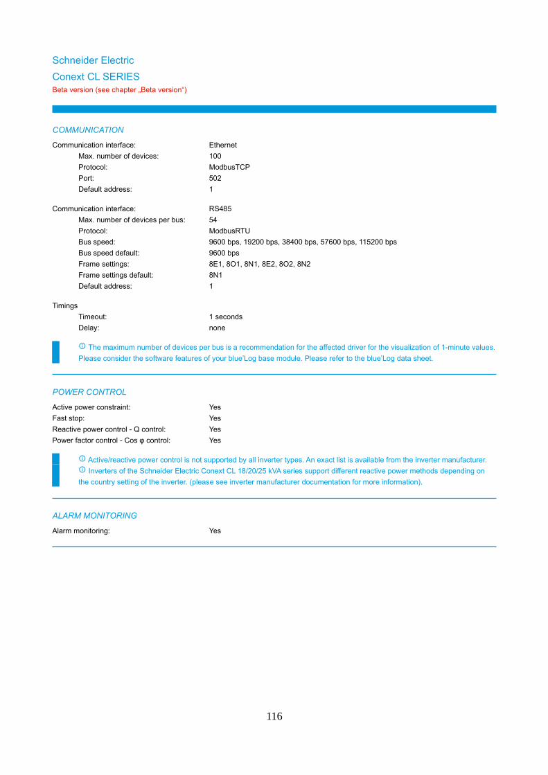
Schneider Electric
Conext CL SERIESBeta version (see chapter „Beta version“)
COMMUNICATION
Communication interface: Ethernet
Max. number of devices: 100
Protocol: ModbusTCP
Port: 502
Default address: 1
Communication interface: RS485
Max. number of devices per bus: 54
Protocol: ModbusRTU
Bus speed: 9600 bps, 19200 bps, 38400 bps, 57600 bps, 115200 bps
Bus speed default: 9600 bps
Frame settings: 8E1, 8O1, 8N1, 8E2, 8O2, 8N2
Frame settings default: 8N1
Default address: 1
Timings
Timeout: 1 seconds
Delay: none
The maximum number of devices per bus is a recommendation for the affected driver for the visualization of 1-minute values.
Please consider the software features of your blue’Log base module. Please refer to the blue’Log data sheet.
POWER CONTROL
Active power constraint: Yes
Fast stop: Yes
Reactive power control - Q control: Yes
Power factor control - Cos φ control: Yes
Active/reactive power control is not supported by all inverter types. An exact list is available from the inverter manufacturer.
Inverters of the Schneider Electric Conext CL 18/20/25 kVA series support different reactive power methods depending on
the country setting of the inverter. (please see inverter manufacturer documentation for more information).
ALARM MONITORING
Alarm monitoring: Yes
116
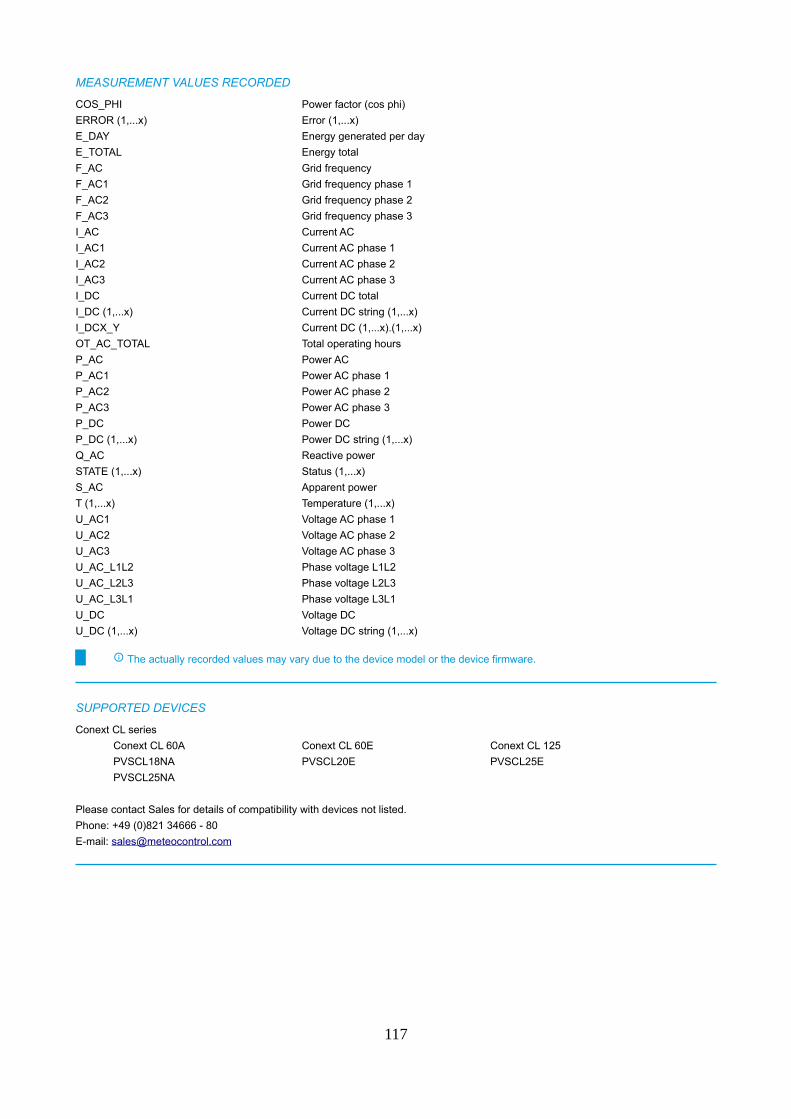
MEASUREMENT VALUES RECORDED
COS_PHI Power factor (cos phi)
ERROR (1,...x) Error (1,...x)
E_DAY Energy generated per day
E_TOTAL Energy total
F_AC Grid frequency
F_AC1 Grid frequency phase 1
F_AC2 Grid frequency phase 2
F_AC3 Grid frequency phase 3
I_AC Current AC
I_AC1 Current AC phase 1
I_AC2 Current AC phase 2
I_AC3 Current AC phase 3
I_DC Current DC total
I_DC (1,...x) Current DC string (1,...x)
I_DCX_Y Current DC (1,...x).(1,...x)
OT_AC_TOTAL Total operating hours
P_AC Power AC
P_AC1 Power AC phase 1
P_AC2 Power AC phase 2
P_AC3 Power AC phase 3
P_DC Power DC
P_DC (1,...x) Power DC string (1,...x)
Q_AC Reactive power
STATE (1,...x) Status (1,...x)
S_AC Apparent power
T (1,...x) Temperature (1,...x)
U_AC1 Voltage AC phase 1
U_AC2 Voltage AC phase 2
U_AC3 Voltage AC phase 3
U_AC_L1L2 Phase voltage L1L2
U_AC_L2L3 Phase voltage L2L3
U_AC_L3L1 Phase voltage L3L1
U_DC Voltage DC
U_DC (1,...x) Voltage DC string (1,...x)
The actually recorded values may vary due to the device model or the device firmware.
SUPPORTED DEVICES
Conext CL series
Conext CL 60A Conext CL 60E Conext CL 125
PVSCL18NA PVSCL20E PVSCL25E
PVSCL25NA
Please contact Sales for details of compatibility with devices not listed.
Phone: +49 (0)821 34666 - 80
E-mail: [email protected]
117
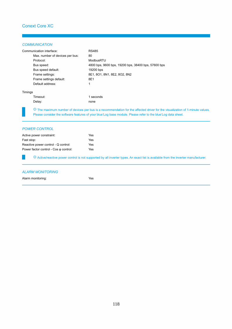
Conext Core XC
COMMUNICATION
Communication interface: RS485
Max. number of devices per bus: 80
Protocol: ModbusRTU
Bus speed: 4800 bps, 9600 bps, 19200 bps, 38400 bps, 57600 bps
Bus speed default: 19200 bps
Frame settings: 8E1, 8O1, 8N1, 8E2, 8O2, 8N2
Frame settings default: 8E1
Default address: 1
Timings
Timeout: 1 seconds
Delay: none
The maximum number of devices per bus is a recommendation for the affected driver for the visualization of 1-minute values.
Please consider the software features of your blue’Log base module. Please refer to the blue’Log data sheet.
POWER CONTROL
Active power constraint: Yes
Fast stop: Yes
Reactive power control - Q control: Yes
Power factor control - Cos φ control: Yes
Active/reactive power control is not supported by all inverter types. An exact list is available from the inverter manufacturer.
ALARM MONITORING
Alarm monitoring: Yes
118
MEASUREMENT VALUES RECORDED
ERROR (1,...x) Error (1,...x)
E_DAY Energy generated per day
E_TOTAL Energy total
F_AC Grid frequency
I_AC Current AC
I_AC1 Current AC phase 1
I_AC2 Current AC phase 2
I_AC3 Current AC phase 3
I_DC Current DC total
OT_AC_TOTAL Total operating hours
P_AC Power AC
P_AC1 Power AC phase 1
P_AC2 Power AC phase 2
P_AC3 Power AC phase 3
P_DC Power DC
Q_AC Reactive power
Q_AC1 Reactive power phase 1
Q_AC2 Reactive power phase 2
Q_AC3 Reactive power phase 3
STATE (1,...x) Status (1,...x)
S_AC Apparent power
S_AC1 Apparent power phase 1
S_AC2 Apparent power phase 2
S_AC3 Apparent power phase 3
T (1,...x) Temperature (1,...x)
U_AC_L1L2 Phase voltage L1L2
U_AC_L2L3 Phase voltage L2L3
U_AC_L3L1 Phase voltage L3L1
U_DC Voltage DC
The actually recorded values may vary due to the device model or the device firmware.
SUPPORTED DEVICES
Conext Core XC series
XC540 XC540-BB XC630
XC630-BB XC680 XC680-BB
Please contact Sales for details of compatibility with devices not listed.
Phone: +49 (0)821 34666 - 80
E-mail: [email protected]
119

Conext SmartGenBeta version (see chapter „Beta version“)
COMMUNICATION
Communication interface: Ethernet
Max. number of devices: 100
Protocol: ModbusTCP
Port: 502
Default address: 1
Communication interface: RS485
Max. number of devices per bus: 42
Protocol: ModbusRTU
Bus speed: 4800 bps, 9600 bps, 19200 bps, 38400 bps, 57600 bps
Bus speed default: 19200 bps
Frame settings: 8E1, 8O1, 8N1, 8E2, 8O2, 8N2
Frame settings default: 8E1
Default address: 1
Timings
Timeout: 2 seconds
Delay: 0.01 seconds
The maximum number of devices per bus is a recommendation for the affected driver for the visualization of 1-minute values.
Please consider the software features of your blue’Log base module. Please refer to the blue’Log data sheet.
Schneider Electric Conext Smartgen inverters consist of 2 inverter modules and one meter.
Therefore the total amount of Smartgen inverters is limited to 33. (33 x 3 submodules = 99 devices).
Please note that IP address range from 192.168.0.0 to 192.168.0.255 is reserved by Schneider Electric Conext SmartGen
inverters. Please make sure that IP addresses in this range do net get used by other devices.
POWER CONTROL
Active power constraint: Yes
Fast stop: Yes
Reactive power control - Q control: Yes
Power factor control - Cos φ control: Yes
Active/reactive power control is not supported by all inverter types. An exact list is available from the inverter manufacturer.
ALARM MONITORING
Alarm monitoring: Yes
120
MEASUREMENT VALUES RECORDED
D_IN (1,...x) Digital input (1,...x)
ERROR (1,...x) Error (1,...x)
E_DAY Energy generated per day
E_TOTAL Energy total
FT_AC_TOTAL Total feed-in hours
F_AC Grid frequency
I_AC1 Current AC phase 1
I_AC2 Current AC phase 2
I_AC3 Current AC phase 3
I_DC Current DC total
I_DCX_Y Current DC (1,...x).(1,...x)
M_AC_E_EXP Active energy (export)
M_AC_E_IMP Active energy (import)
M_AC_F Grid frequency
M_AC_I1 Current AC phase 1
M_AC_I2 Current AC phase 2
M_AC_I3 Current AC phase 3
M_AC_I_N Current, neutral conductor
M_AC_P Power AC
M_AC_P1 Power AC phase 1
M_AC_P2 Power AC phase 2
M_AC_P3 Power AC phase 3
M_AC_PF_COSPHI Power factor (cos phi)
M_AC_PF_COSPHI1 Power factor (cos phi) phase 1
M_AC_PF_COSPHI2 Power factor (cos phi) phase 2
M_AC_PF_COSPHI3 Power factor (cos phi) phase 3
M_AC_Q Reactive power
M_AC_Q1 Reactive power, phase 1
M_AC_Q2 Reactive power, phase 2
M_AC_Q3 Reactive power, phase 3
M_AC_S Apparent power
M_AC_S1 Apparent power phase 1
M_AC_S2 Apparent power phase 2
M_AC_S3 Apparent power phase 3
M_AC_U1 Voltage AC phase 1
M_AC_U2 Voltage AC phase 2
M_AC_U3 Voltage AC phase 3
M_AC_U_L1L2 Phase voltage L1L2
M_AC_U_L2L3 Phase voltage L2L3
M_AC_U_L3L1 Phase voltage L3L1
P_AC Power AC
P_DC Power DC
Q_AC Reactive power
R_ISO Insulation resistance
STATE (1,...x) Status (1,...x)
S_AC Apparent power
T (1,...x) Temperature (1,...x)
U_AC1 Voltage AC phase 1
U_AC2 Voltage AC phase 2
U_AC3 Voltage AC phase 3
U_AC_L1L2 Phase voltage L1L2
U_AC_L2L3 Phase voltage L2L3
U_AC_L3L1 Phase voltage L3L1
U_DC Voltage DC
121
The actually recorded values may vary due to the device model or the device firmware.
The values from the meter module (M_XX_XX) are displayed in the meter device category.
SUPPORTED DEVICES
Conext SmartGen CE series
CS1800 CS2000 CS2200
CS2400
Conext SmartGen NA series
CS1666-1-NA CS1666-2-NA CS1666-3-NA
CS1800 CS2000 CS2200
CS2400
Please contact Sales for details of compatibility with devices not listed.
Phone: +49 (0)821 34666 - 80
E-mail: [email protected]
122
SMA
SHP3, STP, SB, SBS, SI (SunSpec)
COMMUNICATION
Communication interface: Ethernet
Max. number of devices: 100
Protocol: ModbusTCP
Port: 502
Default address: 126
Timings
Timeout: 10 seconds
Delay: none
The maximum number of devices per bus is a recommendation for the affected driver for the visualization of 1-minute values.
Please consider the software features of your blue’Log base module. Please refer to the blue’Log data sheet.
SMA inverters require Speedwire/Webconnect interfaces for communication via SMA SunSpec.
In addition, the Modbus TCP server of the inverters needs to be activated, since this is deactivated at the factory for the
supported SMA devices (please see inverter manufacturer documentation for more information).
POWER CONTROL
Active power constraint: Yes
Fast stop: Yes
Reactive power control - Q control: Yes
Power factor control - Cos φ control: Yes
Active/reactive power control is not supported by all inverter types. An exact list is available from the inverter manufacturer.
Please note that with SMA inverters it is not possible to change the Power Control method via Modbus ("Method switch").
This setting must be done directly at the inverters. Therefore it is not possible to use the blue’Log XC Power Control mode
"Method switch" in combination with SMA inverters.
ALARM MONITORING
Alarm monitoring: Yes
MEASUREMENT VALUES RECORDED
Model 101 Model 102 Model 103
Model 122 Model 123 Model 160
The actually recorded values may vary due to the device model or the device firmware.
123
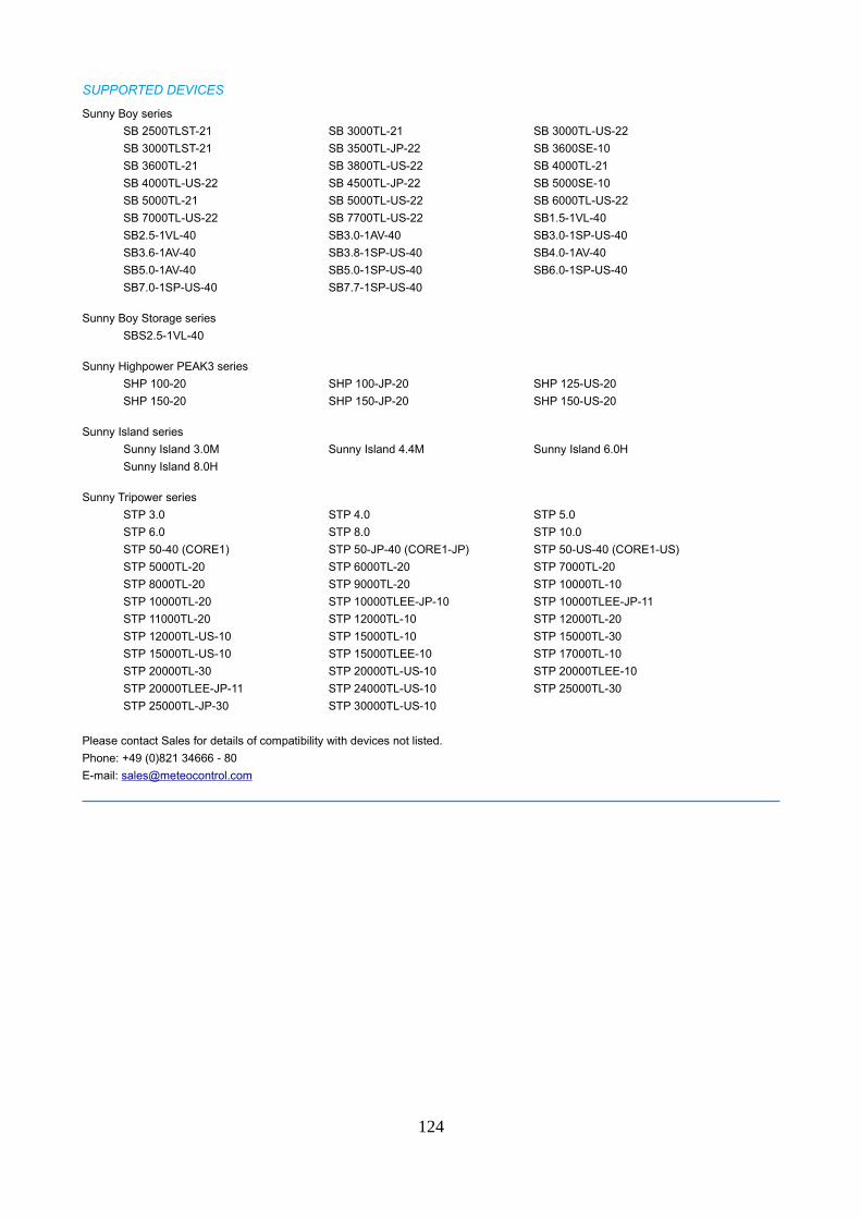
SUPPORTED DEVICES
Sunny Boy series
SB 2500TLST-21 SB 3000TL-21 SB 3000TL-US-22
SB 3000TLST-21 SB 3500TL-JP-22 SB 3600SE-10
SB 3600TL-21 SB 3800TL-US-22 SB 4000TL-21
SB 4000TL-US-22 SB 4500TL-JP-22 SB 5000SE-10
SB 5000TL-21 SB 5000TL-US-22 SB 6000TL-US-22
SB 7000TL-US-22 SB 7700TL-US-22 SB1.5-1VL-40
SB2.5-1VL-40 SB3.0-1AV-40 SB3.0-1SP-US-40
SB3.6-1AV-40 SB3.8-1SP-US-40 SB4.0-1AV-40
SB5.0-1AV-40 SB5.0-1SP-US-40 SB6.0-1SP-US-40
SB7.0-1SP-US-40 SB7.7-1SP-US-40
Sunny Boy Storage series
SBS2.5-1VL-40
Sunny Highpower PEAK3 series
SHP 100-20 SHP 100-JP-20 SHP 125-US-20
SHP 150-20 SHP 150-JP-20 SHP 150-US-20
Sunny Island series
Sunny Island 3.0M Sunny Island 4.4M Sunny Island 6.0H
Sunny Island 8.0H
Sunny Tripower series
STP 3.0 STP 4.0 STP 5.0
STP 6.0 STP 8.0 STP 10.0
STP 50-40 (CORE1) STP 50-JP-40 (CORE1-JP) STP 50-US-40 (CORE1-US)
STP 5000TL-20 STP 6000TL-20 STP 7000TL-20
STP 8000TL-20 STP 9000TL-20 STP 10000TL-10
STP 10000TL-20 STP 10000TLEE-JP-10 STP 10000TLEE-JP-11
STP 11000TL-20 STP 12000TL-10 STP 12000TL-20
STP 12000TL-US-10 STP 15000TL-10 STP 15000TL-30
STP 15000TL-US-10 STP 15000TLEE-10 STP 17000TL-10
STP 20000TL-30 STP 20000TL-US-10 STP 20000TLEE-10
STP 20000TLEE-JP-11 STP 24000TL-US-10 STP 25000TL-30
STP 25000TL-JP-30 STP 30000TL-US-10
Please contact Sales for details of compatibility with devices not listed.
Phone: +49 (0)821 34666 - 80
E-mail: [email protected]
124
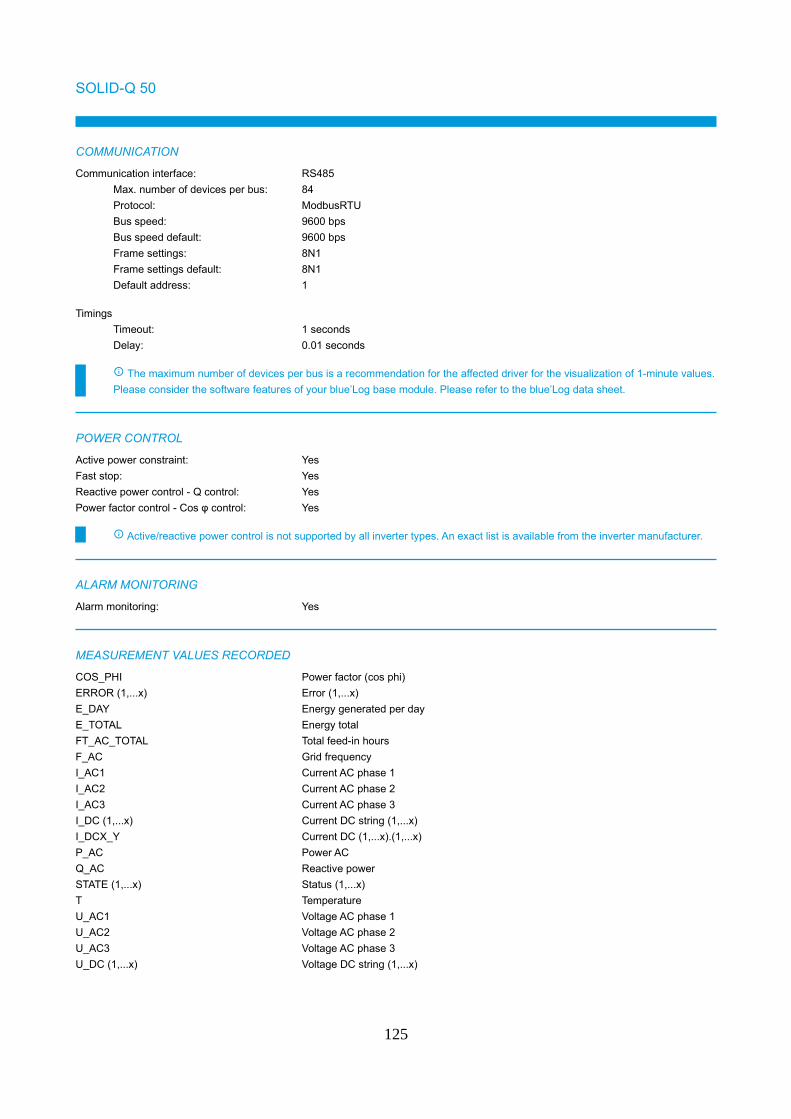
SOLID-Q 50
COMMUNICATION
Communication interface: RS485
Max. number of devices per bus: 84
Protocol: ModbusRTU
Bus speed: 9600 bps
Bus speed default: 9600 bps
Frame settings: 8N1
Frame settings default: 8N1
Default address: 1
Timings
Timeout: 1 seconds
Delay: 0.01 seconds
The maximum number of devices per bus is a recommendation for the affected driver for the visualization of 1-minute values.
Please consider the software features of your blue’Log base module. Please refer to the blue’Log data sheet.
POWER CONTROL
Active power constraint: Yes
Fast stop: Yes
Reactive power control - Q control: Yes
Power factor control - Cos φ control: Yes
Active/reactive power control is not supported by all inverter types. An exact list is available from the inverter manufacturer.
ALARM MONITORING
Alarm monitoring: Yes
MEASUREMENT VALUES RECORDED
COS_PHI Power factor (cos phi)
ERROR (1,...x) Error (1,...x)
E_DAY Energy generated per day
E_TOTAL Energy total
FT_AC_TOTAL Total feed-in hours
F_AC Grid frequency
I_AC1 Current AC phase 1
I_AC2 Current AC phase 2
I_AC3 Current AC phase 3
I_DC (1,...x) Current DC string (1,...x)
I_DCX_Y Current DC (1,...x).(1,...x)
P_AC Power AC
Q_AC Reactive power
STATE (1,...x) Status (1,...x)
T Temperature
U_AC1 Voltage AC phase 1
U_AC2 Voltage AC phase 2
U_AC3 Voltage AC phase 3
U_DC (1,...x) Voltage DC string (1,...x)
125

The actually recorded values may vary due to the device model or the device firmware.
126
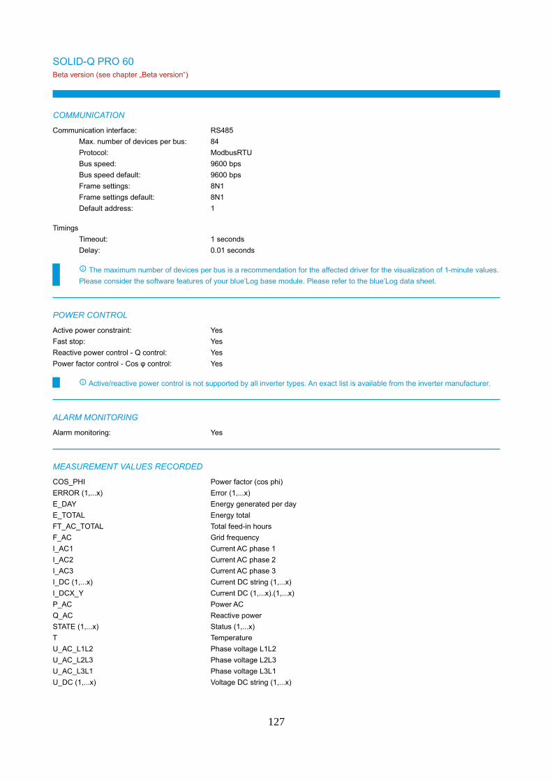
SOLID-Q PRO 60Beta version (see chapter „Beta version“)
COMMUNICATION
Communication interface: RS485
Max. number of devices per bus: 84
Protocol: ModbusRTU
Bus speed: 9600 bps
Bus speed default: 9600 bps
Frame settings: 8N1
Frame settings default: 8N1
Default address: 1
Timings
Timeout: 1 seconds
Delay: 0.01 seconds
The maximum number of devices per bus is a recommendation for the affected driver for the visualization of 1-minute values.
Please consider the software features of your blue’Log base module. Please refer to the blue’Log data sheet.
POWER CONTROL
Active power constraint: Yes
Fast stop: Yes
Reactive power control - Q control: Yes
Power factor control - Cos φ control: Yes
Active/reactive power control is not supported by all inverter types. An exact list is available from the inverter manufacturer.
ALARM MONITORING
Alarm monitoring: Yes
MEASUREMENT VALUES RECORDED
COS_PHI Power factor (cos phi)
ERROR (1,...x) Error (1,...x)
E_DAY Energy generated per day
E_TOTAL Energy total
FT_AC_TOTAL Total feed-in hours
F_AC Grid frequency
I_AC1 Current AC phase 1
I_AC2 Current AC phase 2
I_AC3 Current AC phase 3
I_DC (1,...x) Current DC string (1,...x)
I_DCX_Y Current DC (1,...x).(1,...x)
P_AC Power AC
Q_AC Reactive power
STATE (1,...x) Status (1,...x)
T Temperature
U_AC_L1L2 Phase voltage L1L2
U_AC_L2L3 Phase voltage L2L3
U_AC_L3L1 Phase voltage L3L1
U_DC (1,...x) Voltage DC string (1,...x)
127

The actually recorded values may vary due to the device model or the device firmware.
128
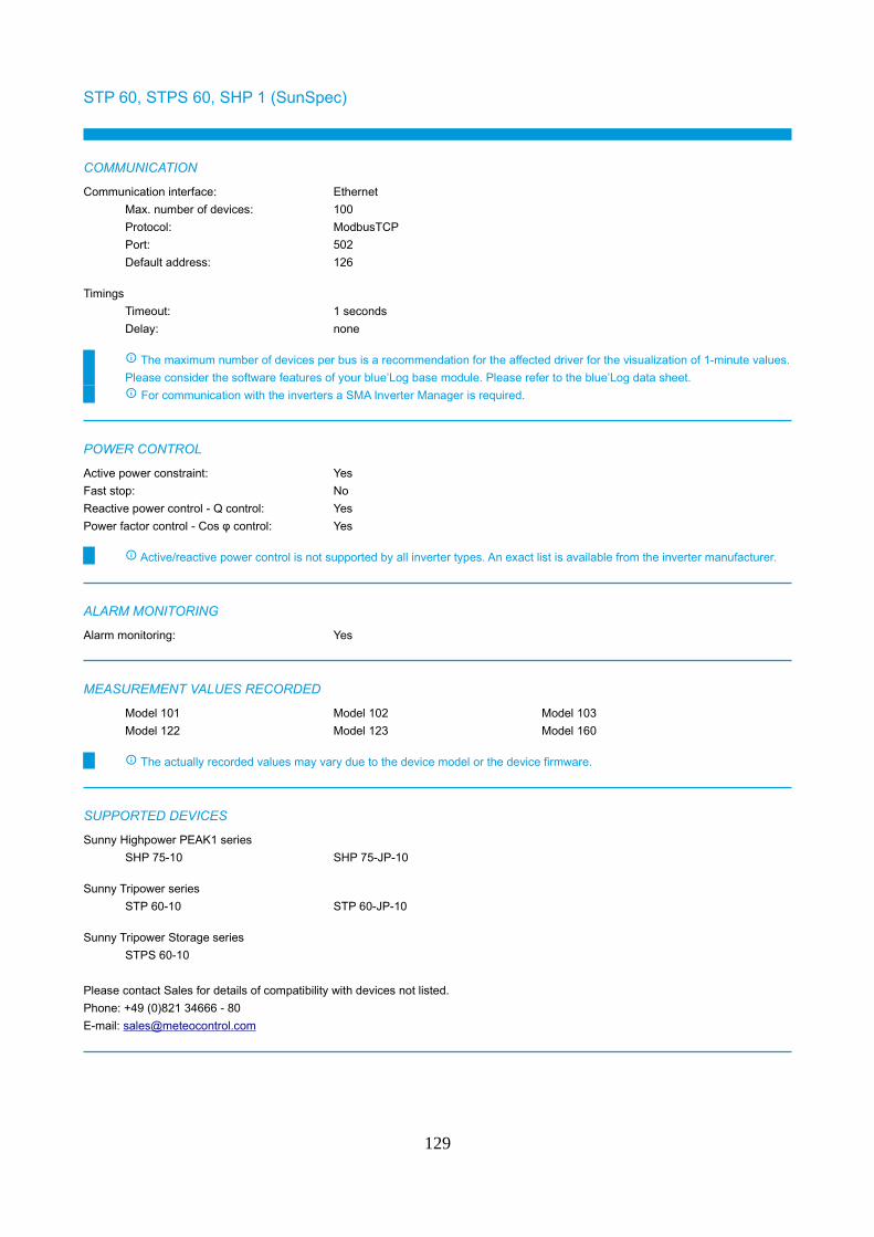
STP 60, STPS 60, SHP 1 (SunSpec)
COMMUNICATION
Communication interface: Ethernet
Max. number of devices: 100
Protocol: ModbusTCP
Port: 502
Default address: 126
Timings
Timeout: 1 seconds
Delay: none
The maximum number of devices per bus is a recommendation for the affected driver for the visualization of 1-minute values.
Please consider the software features of your blue’Log base module. Please refer to the blue’Log data sheet.
For communication with the inverters a SMA Inverter Manager is required.
POWER CONTROL
Active power constraint: Yes
Fast stop: No
Reactive power control - Q control: Yes
Power factor control - Cos φ control: Yes
Active/reactive power control is not supported by all inverter types. An exact list is available from the inverter manufacturer.
ALARM MONITORING
Alarm monitoring: Yes
MEASUREMENT VALUES RECORDED
Model 101 Model 102 Model 103
Model 122 Model 123 Model 160
The actually recorded values may vary due to the device model or the device firmware.
SUPPORTED DEVICES
Sunny Highpower PEAK1 series
SHP 75-10 SHP 75-JP-10
Sunny Tripower series
STP 60-10 STP 60-JP-10
Sunny Tripower Storage series
STPS 60-10
Please contact Sales for details of compatibility with devices not listed.
Phone: +49 (0)821 34666 - 80
E-mail: [email protected]
129
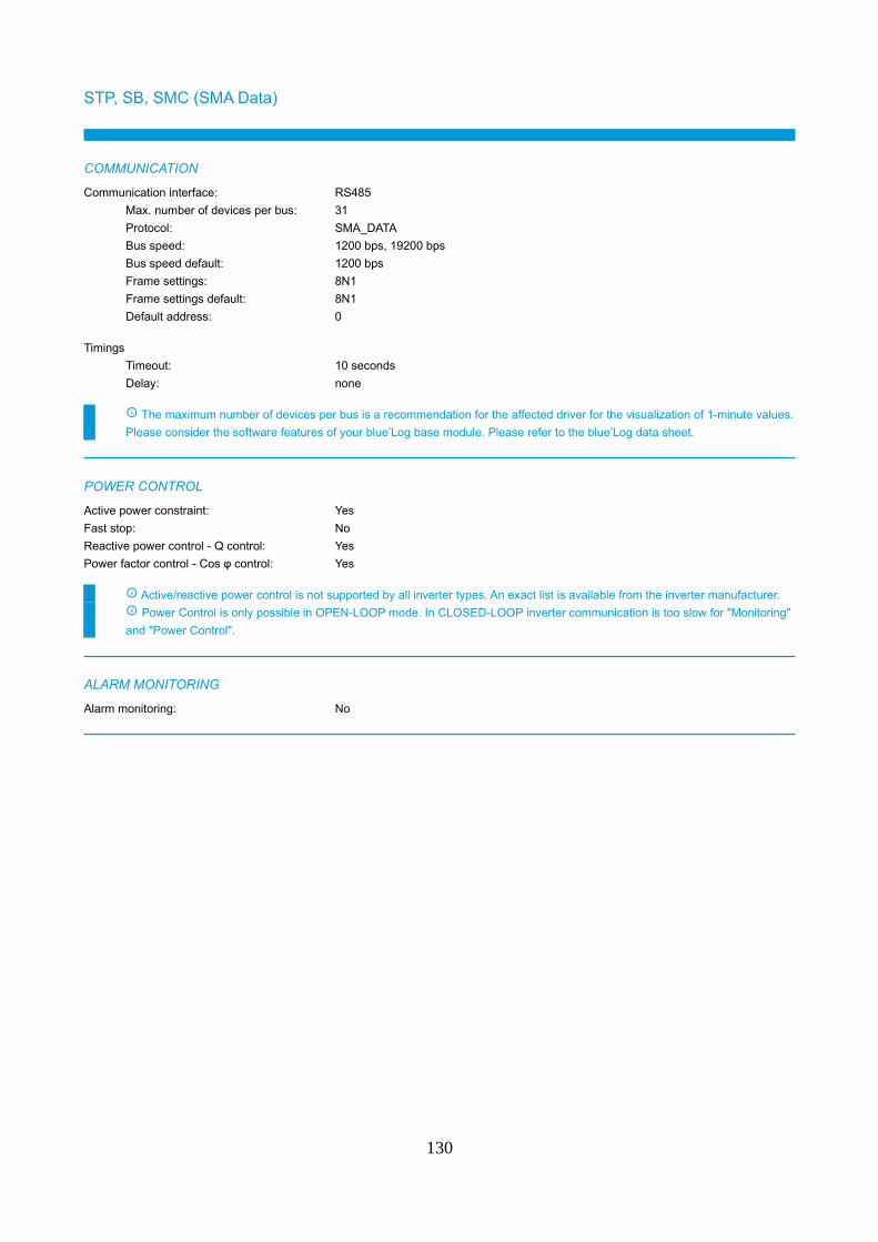
STP, SB, SMC (SMA Data)
COMMUNICATION
Communication interface: RS485
Max. number of devices per bus: 31
Protocol: SMA_DATA
Bus speed: 1200 bps, 19200 bps
Bus speed default: 1200 bps
Frame settings: 8N1
Frame settings default: 8N1
Default address: 0
Timings
Timeout: 10 seconds
Delay: none
The maximum number of devices per bus is a recommendation for the affected driver for the visualization of 1-minute values.
Please consider the software features of your blue’Log base module. Please refer to the blue’Log data sheet.
POWER CONTROL
Active power constraint: Yes
Fast stop: No
Reactive power control - Q control: Yes
Power factor control - Cos φ control: Yes
Active/reactive power control is not supported by all inverter types. An exact list is available from the inverter manufacturer.
Power Control is only possible in OPEN-LOOP mode. In CLOSED-LOOP inverter communication is too slow for "Monitoring"
and "Power Control".
ALARM MONITORING
Alarm monitoring: No
130
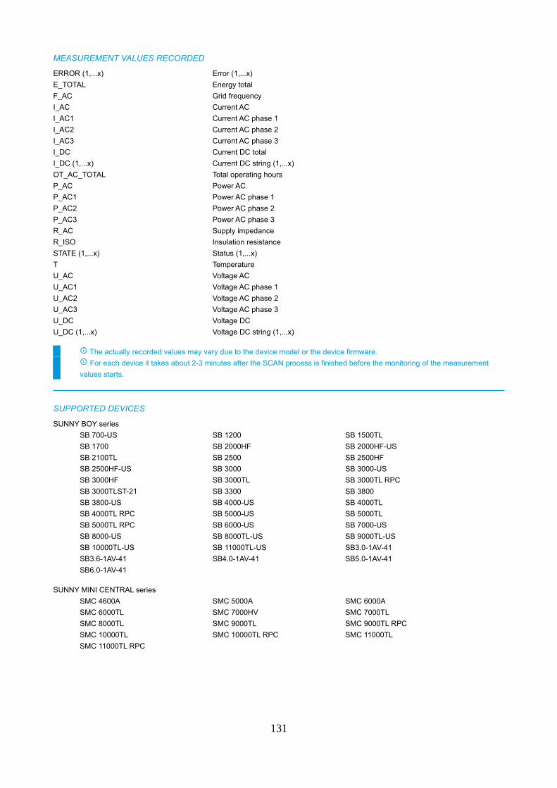
MEASUREMENT VALUES RECORDED
ERROR (1,...x) Error (1,...x)
E_TOTAL Energy total
F_AC Grid frequency
I_AC Current AC
I_AC1 Current AC phase 1
I_AC2 Current AC phase 2
I_AC3 Current AC phase 3
I_DC Current DC total
I_DC (1,...x) Current DC string (1,...x)
OT_AC_TOTAL Total operating hours
P_AC Power AC
P_AC1 Power AC phase 1
P_AC2 Power AC phase 2
P_AC3 Power AC phase 3
R_AC Supply impedance
R_ISO Insulation resistance
STATE (1,...x) Status (1,...x)
T Temperature
U_AC Voltage AC
U_AC1 Voltage AC phase 1
U_AC2 Voltage AC phase 2
U_AC3 Voltage AC phase 3
U_DC Voltage DC
U_DC (1,...x) Voltage DC string (1,...x)
The actually recorded values may vary due to the device model or the device firmware.
For each device it takes about 2-3 minutes after the SCAN process is finished before the monitoring of the measurement
values starts.
SUPPORTED DEVICES
SUNNY BOY series
SB 700-US SB 1200 SB 1500TL
SB 1700 SB 2000HF SB 2000HF-US
SB 2100TL SB 2500 SB 2500HF
SB 2500HF-US SB 3000 SB 3000-US
SB 3000HF SB 3000TL SB 3000TL RPC
SB 3000TLST-21 SB 3300 SB 3800
SB 3800-US SB 4000-US SB 4000TL
SB 4000TL RPC SB 5000-US SB 5000TL
SB 5000TL RPC SB 6000-US SB 7000-US
SB 8000-US SB 8000TL-US SB 9000TL-US
SB 10000TL-US SB 11000TL-US SB3.0-1AV-41
SB3.6-1AV-41 SB4.0-1AV-41 SB5.0-1AV-41
SB6.0-1AV-41
SUNNY MINI CENTRAL series
SMC 4600A SMC 5000A SMC 6000A
SMC 6000TL SMC 7000HV SMC 7000TL
SMC 8000TL SMC 9000TL SMC 9000TL RPC
SMC 10000TL SMC 10000TL RPC SMC 11000TL
SMC 11000TL RPC
131
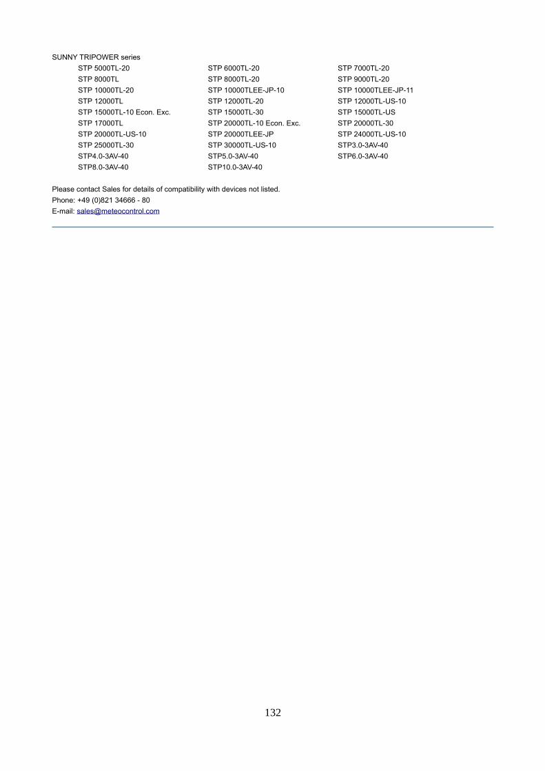
SUNNY TRIPOWER series
STP 5000TL-20 STP 6000TL-20 STP 7000TL-20
STP 8000TL STP 8000TL-20 STP 9000TL-20
STP 10000TL-20 STP 10000TLEE-JP-10 STP 10000TLEE-JP-11
STP 12000TL STP 12000TL-20 STP 12000TL-US-10
STP 15000TL-10 Econ. Exc. STP 15000TL-30 STP 15000TL-US
STP 17000TL STP 20000TL-10 Econ. Exc. STP 20000TL-30
STP 20000TL-US-10 STP 20000TLEE-JP STP 24000TL-US-10
STP 25000TL-30 STP 30000TL-US-10 STP3.0-3AV-40
STP4.0-3AV-40 STP5.0-3AV-40 STP6.0-3AV-40
STP8.0-3AV-40 STP10.0-3AV-40
Please contact Sales for details of compatibility with devices not listed.
Phone: +49 (0)821 34666 - 80
E-mail: [email protected]
132
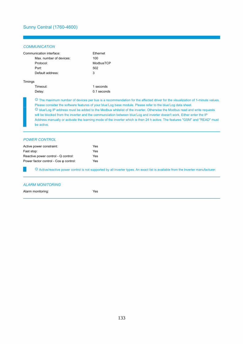
Sunny Central (1760-4600)
COMMUNICATION
Communication interface: Ethernet
Max. number of devices: 100
Protocol: ModbusTCP
Port: 502
Default address: 3
Timings
Timeout: 1 seconds
Delay: 0.1 seconds
The maximum number of devices per bus is a recommendation for the affected driver for the visualization of 1-minute values.
Please consider the software features of your blue’Log base module. Please refer to the blue’Log data sheet.
blue'Log IP address must be added to the Modbus whitelist of the inverter. Otherwise the Modbus read and write requests
will be blocked from the inverter and the communciation between blue’Log and inverter doesn't work. Either enter the IP
Address manually or activate the learning mode of the inverter which is then 24 h active. The features "GSM" and "READ" must
be active.
POWER CONTROL
Active power constraint: Yes
Fast stop: Yes
Reactive power control - Q control: Yes
Power factor control - Cos φ control: Yes
Active/reactive power control is not supported by all inverter types. An exact list is available from the inverter manufacturer.
ALARM MONITORING
Alarm monitoring: Yes
133
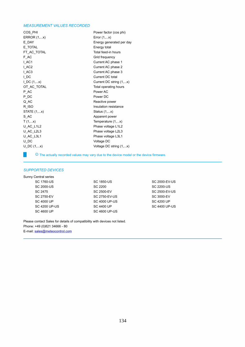
MEASUREMENT VALUES RECORDED
COS_PHI Power factor (cos phi)
ERROR (1,...x) Error (1,...x)
E_DAY Energy generated per day
E_TOTAL Energy total
FT_AC_TOTAL Total feed-in hours
F_AC Grid frequency
I_AC1 Current AC phase 1
I_AC2 Current AC phase 2
I_AC3 Current AC phase 3
I_DC Current DC total
I_DC (1,...x) Current DC string (1,...x)
OT_AC_TOTAL Total operating hours
P_AC Power AC
P_DC Power DC
Q_AC Reactive power
R_ISO Insulation resistance
STATE (1,...x) Status (1,...x)
S_AC Apparent power
T (1,...x) Temperature (1,...x)
U_AC_L1L2 Phase voltage L1L2
U_AC_L2L3 Phase voltage L2L3
U_AC_L3L1 Phase voltage L3L1
U_DC Voltage DC
U_DC (1,...x) Voltage DC string (1,...x)
The actually recorded values may vary due to the device model or the device firmware.
SUPPORTED DEVICES
Sunny Central series
SC 1760-US SC 1850-US SC 2000-EV-US
SC 2000-US SC 2200 SC 2200-US
SC 2475 SC 2500-EV SC 2500-EV-US
SC 2750-EV SC 2750-EV-US SC 3000-EV
SC 4000 UP SC 4000 UP-US SC 4200 UP
SC 4200 UP-US SC 4400 UP SC 4400 UP-US
SC 4600 UP SC 4600 UP-US
Please contact Sales for details of compatibility with devices not listed.
Phone: +49 (0)821 34666 - 80
E-mail: [email protected]
134
Sunny Central (CP, CP-US, CP-JP, HE)
COMMUNICATION
Communication interface: Ethernet
Max. number of devices: 100
Protocol: ModbusTCP
Port: 502
Default address: 1
Timings
Timeout: 5 seconds
Delay: 0.25 seconds
The maximum number of devices per bus is a recommendation for the affected driver for the visualization of 1-minute values.
Please consider the software features of your blue’Log base module. Please refer to the blue’Log data sheet.
Recommendation for 1 minute interval data is to limit the maximum number of devices per WebBox / SC-COM to 6. (typical 1
Inverter and 5 String Monitoring Units)
POWER CONTROL
Active power constraint: Yes
Fast stop: Yes
Reactive power control - Q control: Yes
Power factor control - Cos φ control: Yes
Active/reactive power control is not supported by all inverter types. An exact list is available from the inverter manufacturer.
Power Control is only supported if the inverter is equipped with SC-COM. If the inverter is equipped with WebBox please
contact SMA service about an upgrade to SC-COM.
ALARM MONITORING
Alarm monitoring: Yes
135
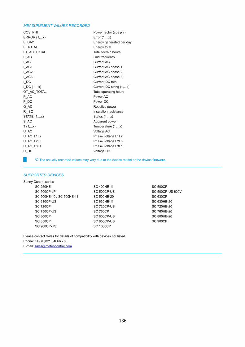
MEASUREMENT VALUES RECORDED
COS_PHI Power factor (cos phi)
ERROR (1,...x) Error (1,...x)
E_DAY Energy generated per day
E_TOTAL Energy total
FT_AC_TOTAL Total feed-in hours
F_AC Grid frequency
I_AC Current AC
I_AC1 Current AC phase 1
I_AC2 Current AC phase 2
I_AC3 Current AC phase 3
I_DC Current DC total
I_DC (1,...x) Current DC string (1,...x)
OT_AC_TOTAL Total operating hours
P_AC Power AC
P_DC Power DC
Q_AC Reactive power
R_ISO Insulation resistance
STATE (1,...x) Status (1,...x)
S_AC Apparent power
T (1,...x) Temperature (1,...x)
U_AC Voltage AC
U_AC_L1L2 Phase voltage L1L2
U_AC_L2L3 Phase voltage L2L3
U_AC_L3L1 Phase voltage L3L1
U_DC Voltage DC
The actually recorded values may vary due to the device model or the device firmware.
SUPPORTED DEVICES
Sunny Central series
SC 250HE SC 400HE-11 SC 500CP
SC 500CP-JP SC 500CP-US SC 500CP-US 600V
SC 500HE-10 / SC 500HE-11 SC 500HE-20 SC 630CP
SC 630CP-US SC 630HE-11 SC 630HE-20
SC 720CP SC 720CP-US SC 720HE-20
SC 750CP-US SC 760CP SC 760HE-20
SC 800CP SC 800CP-US SC 800HE-20
SC 850CP SC 850CP-US SC 900CP
SC 900CP-US SC 1000CP
Please contact Sales for details of compatibility with devices not listed.
Phone: +49 (0)821 34666 - 80
E-mail: [email protected]
136
Sunny IslandBeta version (see chapter „Beta version“)
COMMUNICATION
Communication interface: Ethernet
Max. number of devices: 100
Protocol: ModbusTCP
Port: 502
Default address: 3
Timings
Timeout: 10 seconds
Delay: none
The maximum number of devices per bus is a recommendation for the affected driver for the visualization of 1-minute values.
Please consider the software features of your blue’Log base module. Please refer to the blue’Log data sheet.
Connection of maximum 50 SMA Sunny Islands to one blue'Log possible as 1 Sunny Island consists of 1 inverter + 1 battery.
POWER CONTROL
Active power constraint: Yes
Fast stop: Yes
Reactive power control - Q control: Yes
Power factor control - Cos φ control: Yes
Active/reactive power control is not supported by all inverter types. An exact list is available from the inverter manufacturer.
Please note that with SMA inverters it is not possible to change the Power Control method via Modbus ("Method switch").
This setting must be done directly at the inverters. Therefore it is not possible to use the blue’Log XC Power Control mode
"Method switch" in combination with SMA inverters.
ALARM MONITORING
Alarm monitoring: Yes
137
MEASUREMENT VALUES RECORDED
B_CAPACITY Nominal capacity
B_CHARGE_LEVEL Charging status
B_E_EXP Energy from storage system
B_E_IMP Energy to storage system
B_I_DC Battery current
B_LIM_I_CHARGE Maximum charge current
B_LIM_I_DISCHARGE Maximum discharge current
B_LIM_U_DISCHARGE Battery final cut-off voltage
B_OT_TOTAL Operating Hours
B_SOH Current battery capacity in %
B_U_DC Battery voltage
COS_PHI Power factor (cos phi)
ERROR (1,...x) Error (1,...x)
E_TOTAL Energy total
F_AC Grid frequency
I_AC1 Current AC phase 1
I_AC2 Current AC phase 2
I_AC3 Current AC phase 3
P_AC Power AC
P_AC1 Power AC phase 1
P_AC2 Power AC phase 2
P_AC3 Power AC phase 3
P_DC Power DC
Q_AC1 Reactive power phase 1
Q_AC2 Reactive power phase 2
Q_AC3 Reactive power phase 3
STATE (1,...x) Status (1,...x)
T (1,...x) Temperature (1,...x)
U_AC1 Voltage AC phase 1
U_AC2 Voltage AC phase 2
U_AC3 Voltage AC phase 3
The actually recorded values may vary due to the device model or the device firmware.
SUPPORTED DEVICES
Sunny Island series
SI3.0M-11 SI4.4M-11 SI4.4M-12
SI6.0H-11 SI6.0H-12 SI8.0H-11
SI8.0H-12
Please contact Sales for details of compatibility with devices not listed.
Phone: +49 (0)821 34666 - 80
E-mail: [email protected]
138
SOFARSOLAR
Sofar 1-40KWBeta version (see chapter „Beta version“)
COMMUNICATION
Communication interface: Ethernet
Max. number of devices: 100
Protocol: ModbusTCP
Port: 502
Default address: 1
Communication interface: RS485
Max. number of devices per bus: 16
Protocol: ModbusRTU
Bus speed: 9600 bps
Bus speed default: 9600 bps
Frame settings: 8N1
Frame settings default: 8N1
Default address: 1
Timings
Timeout: 1 seconds
Delay: 0.5 seconds
The maximum number of devices per bus is a recommendation for the affected driver for the visualization of 1-minute values.
Please consider the software features of your blue’Log base module. Please refer to the blue’Log data sheet.
POWER CONTROL
Active power constraint: No
Fast stop: No
Reactive power control - Q control: No
Power factor control - Cos φ control: No
Active/reactive power control is not supported by all inverter types. An exact list is available from the inverter manufacturer.
ALARM MONITORING
Alarm monitoring: Yes
139
MEASUREMENT VALUES RECORDED
ERROR (1,...x) Error (1,...x)
E_DAY Energy generated per day
E_TOTAL Energy total
FT_AC_TOTAL Total feed-in hours
F_AC Grid frequency
I_AC1 Current AC phase 1
I_AC2 Current AC phase 2
I_AC3 Current AC phase 3
I_DC (1,...x) Current DC string (1,...x)
I_DCX_Y Current DC (1,...x).(1,...x)
P_AC Power AC
P_AC1 Power AC phase 1
P_AC2 Power AC phase 2
Q_AC Reactive power
STATE (1,...x) Status (1,...x)
T (1,...x) Temperature (1,...x)
U_AC1 Voltage AC phase 1
U_AC2 Voltage AC phase 2
U_AC3 Voltage AC phase 3
U_DC (1,...x) Voltage DC string (1,...x)
The actually recorded values may vary due to the device model or the device firmware.
SUPPORTED DEVICES
Sofar 1-40KW series
TL30000 TL33000 TL36000
TL40000
Please contact Sales for details of compatibility with devices not listed.
Phone: +49 (0)821 34666 - 80
E-mail: [email protected]
140
SolarEdge
SE (SunSpec)
COMMUNICATION
Communication interface: Ethernet
Max. number of devices: 100
Protocol: ModbusTCP
Port: 502
Default address: 1
Communication interface: RS485
Max. number of devices per bus: 100
Protocol: ModbusRTU
Bus speed: 9600 bps, 19200 bps, 38400 bps, 57600 bps, 115200 bps
Bus speed default: 115200 bps
Frame settings: 8N1
Frame settings default: 8N1
Default address: 1
Timings
Timeout: 1 seconds
Delay: none
The maximum number of devices per bus is a recommendation for the affected driver for the visualization of 1-minute values.
Please consider the software features of your blue’Log base module. Please refer to the blue’Log data sheet.
Only devices with firmware 3.2462 or higher get supported.
POWER CONTROL
Active power constraint: Yes
Fast stop: No
Reactive power control - Q control: No
Power factor control - Cos φ control: Yes
Active/reactive power control is not supported by all inverter types. An exact list is available from the inverter manufacturer.
Switching between different active/reactive power control setpoint methods may lead to a stop in production of the SolarEdge
inverters of up to 10 seconds. This may affect operation with many power control setpoint methods.
ALARM MONITORING
Alarm monitoring: Yes
MEASUREMENT VALUES RECORDED
Model 101 Model 102 Model 103
Model 122 Model 123 Model 160
The actually recorded values may vary due to the device model or the device firmware.
141
SUPPORTED DEVICES
SE series
SE3K SE4K SE5K
SE6K SE7K SE8K
SE9K SE10K SE10KUS
SE12.5K SE15K SE16K
SE17K SE20KUS SE25K
SE27.6K SE33.3K SE33.3KUS
SE50K SE55K SE66.6K
SE82.8K SE100K SE1000M
SE1500M SE2000M SE2200H
SE3000H SE3500H SE3680H
SE4000H SE5000H
Meters connected to the CCG do not get supported.
Please contact Sales for details of compatibility with devices not listed.
Phone: +49 (0)821 34666 - 80
E-mail: [email protected]
142
SolarMax
SolarMax Inverter (MaxComm Protocol)
COMMUNICATION
Communication interface: Ethernet
Max. number of devices: 100
Protocol: MAX_COMM_ETHERNET
Port: 12345
Default address: 1
Communication interface: RS485
Max. number of devices per bus: 100
Protocol: MAX_COMM_SERIAL
Bus speed: 19200 bps
Bus speed default: 19200 bps
Frame settings: 8N1
Frame settings default: 8N1
Default address: 1
Timings
Timeout: 3 seconds
Delay: none
The maximum number of devices per bus is a recommendation for the affected driver for the visualization of 1-minute values.
Please consider the software features of your blue’Log base module. Please refer to the blue’Log data sheet.
POWER CONTROL
Active power constraint: Yes
Fast stop: Yes
Reactive power control - Q control: Yes
Power factor control - Cos φ control: Yes
Active/reactive power control is not supported by all inverter types. An exact list is available from the inverter manufacturer.
Power Control is only possible in OPEN-LOOP mode. In CLOSED-LOOP inverter communication is too slow for "Monitoring"
and "Power Control".
C series string inverters (2000C - 6000C) don't support Power Control.
S, P, and TP series string inverters support only active Power Control.
C, C-SV, S, and TS (not TS-SV) series central inverters support only active Power Control.
6MT2 CH, 12MT2 A, 15MT3 A and 18MT3 A inverters support only active Power Control.
Only 330, 660, 990, 1320 TS-SV inverters with software version ≥ 1.0.16053 are supporting PowerControl.
Only 360, 720, 1080, 1440 TS-SV inverters with software version ≥ 1.0.16086 are supporting PowerControl.
Only MT inverters with software version ≥ 1.0.16830 are supporting PowerControl.
Only P inverters with software version ≥ 2.1.0 are supporting active PowerControl.
ALARM MONITORING
Alarm monitoring: Yes
143
MEASUREMENT VALUES RECORDED
ERROR (1,...x) Error (1,...x)
E_DAY Energy generated per day
E_TOTAL Energy total
F_AC Grid frequency
I_AC Current AC
I_AC1 Current AC phase 1
I_AC2 Current AC phase 2
I_AC3 Current AC phase 3
I_DC Current DC total
I_DC (1,...x) Current DC string (1,...x)
OT_AC_TOTAL Total operating hours
P_AC Power AC
P_DC Power DC
P_DC (1,...x) Power DC string (1,...x)
Q_AC Reactive power
STATE (1,...x) Status (1,...x)
S_AC Apparent power
T (1,...x) Temperature (1,...x)
U_AC Voltage AC
U_AC1 Voltage AC phase 1
U_AC2 Voltage AC phase 2
U_AC3 Voltage AC phase 3
U_AC_L1L2 Phase voltage L1L2
U_AC_L2L3 Phase voltage L2L3
U_AC_L3L1 Phase voltage L3L1
U_DC Voltage DC
U_DC (1,...x) Voltage DC string (1,...x)
The actually recorded values may vary due to the device model or the device firmware.
SUPPORTED DEVICES
Central inverters series
20 20C 25C
30 30C 35C
40 45 50C
50TS 60 75TS A
80C 80TS 100
100C 100TS 125
300C 300TS MT 300TS ST
330C-SV 330TS-SV MT 330TS-SV ST
360TS-SV MT 360TS-SV ST 660TS-SV MT
660TS-SV ST 720TS-SV MT 720TS-SV ST
990TS-SV MT 990TS-SV ST 1080TS-SV MT
1080TS-SV ST 1320TS-SV MT 1320TS-SV ST
1440TS-SV MT 1440TS-SV ST
144
String inverters series
4TP 5TP2 6MT2
6MT2 CH 6SMT 6TP2
7TP2 8MT2 8SMT
10MT 10MT2 10SMT
12MT2 A 13MT2 13MT3
13SMT 15MT2 15MT3
15MT3 A 15SMT 17SHT
18MT3 A 18MT3 SV 20HT2
20HT4 20S 20SHT
22SHT 25HT2 25HT4
25SHT 28SHT 30HT4
30SHT 32HT2 32HT4
35S 1000SP 1500SP
2000 2000C 2000E
2000P 2000S 2000SP
2500SP 3000 3000C
3000E 3000P 3000S
3000SP 3600SP 4000
4000C 4000E 4000P
4000SP 4200C 4200S
4600P 4600SP 5000P
5000SP 6000C 6000E
6000S
Please contact Sales for details of compatibility with devices not listed.
Phone: +49 (0)821 34666 - 80
E-mail: [email protected]
145
SunGrow
SG 3125-3400HV/HV-MVBeta version (see chapter „Beta version“)
COMMUNICATION
Communication interface: Ethernet
Max. number of devices: 100
Protocol: ModbusTCP
Port: 502
Default address: 1
Communication interface: RS485
Max. number of devices per bus: 77
Protocol: ModbusRTU
Bus speed: 9600 bps
Bus speed default: 9600 bps
Frame settings: 8N1
Frame settings default: 8N1
Default address: 1
Timings
Timeout: 5 seconds
Delay: 0.025 seconds
The maximum number of devices per bus is a recommendation for the affected driver for the visualization of 1-minute values.
Please consider the software features of your blue’Log base module. Please refer to the blue’Log data sheet.
Sungrow Turnkey Stations consist of several module/inverter units. This affects the total amount of devices that can be
connected to the blue’Log. This station consists of 4 devices (3 inverter and 1 string combiner).
POWER CONTROL
Active power constraint: Yes
Fast stop: Yes
Reactive power control - Q control: Yes
Power factor control - Cos φ control: Yes
Active/reactive power control is not supported by all inverter types. An exact list is available from the inverter manufacturer.
ALARM MONITORING
Alarm monitoring: Yes
146
MEASUREMENT VALUES RECORDED
COS_PHI Power factor (cos phi)
ERROR (1,...x) Error (1,...x)
E_DAY Energy generated per day
E_TOTAL Energy total
F_AC Grid frequency
I (1,...x) Current DC (1,...x)
I_AC1 Current AC phase 1
I_AC2 Current AC phase 2
I_AC3 Current AC phase 3
I_DC Current DC total
OT_AC_TOTAL Total operating hours
P_AC Power AC
P_DC Power DC
Q_AC Reactive power
R_ISO Insulation resistance
STATE (1,...x) Status (1,...x)
T (1,...x) Temperature (1,...x)
U_AC_L1L2 Phase voltage L1L2
U_AC_L2L3 Phase voltage L2L3
U_AC_L3L1 Phase voltage L3L1
U_DC Voltage DC
U_DC_NE Voltage DC negative pole to earth
The actually recorded values may vary due to the device model or the device firmware.
SUPPORTED DEVICES
SG3125HV SG3125HV-MV SG3400HV
SG3400HV-MV
Please contact Sales for details of compatibility with devices not listed.
Phone: +49 (0)821 34666 - 80
E-mail: [email protected]
147

SG1 - SG125 (string inverter)
COMMUNICATION
Communication interface: Ethernet
Max. number of devices: 100
Protocol: ModbusTCP
Port: 502
Default address: 1
Communication interface: RS485
Max. number of devices per bus: 46
Protocol: ModbusRTU
Bus speed: 9600 bps, 19200 bps
Bus speed default: 9600 bps
Frame settings: 8O1, 8O2, 8N1, 8N2, 8E1, 8E2
Frame settings default: 8N1
Default address: 1
Timings
Timeout: 5 seconds
Delay: none
The maximum number of devices per bus is a recommendation for the affected driver for the visualization of 1-minute values.
Please consider the software features of your blue’Log base module. Please refer to the blue’Log data sheet.
POWER CONTROL
Active power constraint: Yes
Fast stop: Yes
Reactive power control - Q control: Yes
Power factor control - Cos φ control: Yes
Active/reactive power control is not supported by all inverter types. An exact list is available from the inverter manufacturer.
ALARM MONITORING
Alarm monitoring: Yes
148
MEASUREMENT VALUES RECORDED
COS_PHI Power factor (cos phi)
ERROR (1,...x) Error (1,...x)
E_DAY Energy generated per day
E_TOTAL Energy total
F_AC Grid frequency
I_AC Current AC
I_AC1 Current AC phase 1
I_AC2 Current AC phase 2
I_AC3 Current AC phase 3
I_DC (1,...x) Current DC string (1,...x)
I_DCX_Y Current DC (1,...x).(1,...x)
OT_AC_TOTAL Total operating hours
P_AC Power AC
P_DC Power DC
Q_AC Reactive power
R_ISO Insulation resistance
STATE (1,...x) Status (1,...x)
T Temperature
U_AC Voltage AC
U_AC1 Voltage AC phase 1
U_AC2 Voltage AC phase 2
U_AC3 Voltage AC phase 3
U_AC_L1L2 Phase voltage L1L2
U_AC_L2L3 Phase voltage L2L3
U_AC_L3L1 Phase voltage L3L1
U_DC (1,...x) Voltage DC string (1,...x)
The actually recorded values may vary due to the device model or the device firmware.
149
SUPPORTED DEVICES
String Inverter series
LP_P34KSG SG2K5-S SG3K6-D
SG3KTL-EC SG4K6-D SG4KTL-EC
SG5KTL-EC SG5KTL-MT SG6KTL-EC
SG6KTL-MT SG8KTL-EC SG8KTL-M
SG10KTL SG10KTL-EC SG10KTL-M
SG10KTL-MT SG12KTL SG12KTL-EC
SG12KTL-M SG15KTL SG15KTL-M
SG16K6J SG17KTL-M SG20KTL
SG20KTL-M SG20KU SG25CX-SA
SG30CX SG30KJ SG30KTL
SG30KTL_V31 SG30KTL-M SG30KTL-M-V31
SG30KU SG33CX SG33CX-US
SG33K3J SG33KTL-M SG33KTL-M-20
SG33KTL-M-V2 SG34KJ SG36KTL
SG36KTL-M SG36KTL-M-20 SG36KTL-M-V2
SG36KU SG40CX SG40KTL
SG40KTL_V21 SG40KTL-M SG49K5J
SG50CX SG50KTL SG50KTL-M
SG50KTL-M-20 SG50KTL-M-V2 SG55CX-US
SG60KTL SG60KTL-M SG60KU
SG60KU-M SG80BF SG80HV
SG80KTL SG80KTL-M SG80KTL-M-20
SG85BF SG100CX SG100CX-JP
SG110CX SG110HV-M SG111HV
SG125HV SG125HV-20 SG132TX
SG136TX SG150TX SG225HX
SG250HX SG250HX-IN SG250HX-US
Please contact Sales for details of compatibility with devices not listed.
Phone: +49 (0)821 34666 - 80
E-mail: [email protected]
150
SG500 - SG2500 HV/MV (turnkey station)
COMMUNICATION
Communication interface: Ethernet
Max. number of devices: 100
Protocol: ModbusTCP
Port: 502
Default address: 1
Communication interface: RS485
Max. number of devices per bus: 63
Protocol: ModbusRTU
Bus speed: 9600 bps
Bus speed default: 9600 bps
Frame settings: 8N1
Frame settings default: 8N1
Default address: 1
Timings
Timeout: 5 seconds
Delay: none
The maximum number of devices per bus is a recommendation for the affected driver for the visualization of 1-minute values.
Please consider the software features of your blue’Log base module. Please refer to the blue’Log data sheet.
Sungrow Turnkey Stations consist of several module/inverter units (up to 4).
Depending on the amount of module/inverter units the total amount of devices varies that can be connected to one blue’Log
(e.g. 1 x Sungrow Turnkey Station with 4 module/inverter units = 4 devices).
POWER CONTROL
Active power constraint: Yes
Fast stop: Yes
Reactive power control - Q control: Yes
Power factor control - Cos φ control: Yes
Active/reactive power control is not supported by all inverter types. An exact list is available from the inverter manufacturer.
ALARM MONITORING
Alarm monitoring: Yes
151
MEASUREMENT VALUES RECORDED
COS_PHI Power factor (cos phi)
ERROR (1,...x) Error (1,...x)
E_DAY Energy generated per day
E_TOTAL Energy total
F_AC Grid frequency
I_AC1 Current AC phase 1
I_AC2 Current AC phase 2
I_AC3 Current AC phase 3
I_DC Current DC total
I_DCX_Y Current DC (1,...x).(1,...x)
OT_AC_TOTAL Total operating hours
P_AC Power AC
P_DC Power DC
Q_AC Reactive power
R_ISO Insulation resistance
STATE (1,...x) Status (1,...x)
T (1,...x) Temperature (1,...x)
U_AC_L1L2 Phase voltage L1L2
U_AC_L2L3 Phase voltage L2L3
U_AC_L3L1 Phase voltage L3L1
U_DC Voltage DC
U_DC_NE Voltage DC negative pole to earth
The actually recorded values may vary due to the device model or the device firmware.
SUPPORTED DEVICES
Turnkey Station series
SG500MX SG500MX-M SG630MX
SG630MX-M SG750MX SG800MX
SG1000 SG1000HV SG1000MX
SG1250 SG1250-MV SG1250HV
SG1250UD SG1500/SG1500UD SG1500HV
SG2000 SG2000-MV SG2500
SG2500-MV SG2500HV SG2500HV-MV
SG2500U SG2500UD SG2500UD-MV
Please contact Sales for details of compatibility with devices not listed.
Phone: +49 (0)821 34666 - 80
E-mail: [email protected]
152
SunSpec Alliance
Compatible inverter
COMMUNICATION
Communication interface: Ethernet
Max. number of devices: 100
Protocol: ModbusTCP
Port: 502
Default address: 1
Communication interface: RS485
Max. number of devices per bus: 51
Protocol: ModbusRTU
Bus speed: 9600 bps, 19200 bps, 38400 bps, 57600 bps, 115200 bps
Bus speed default: 9600 bps
Frame settings: 8N1
Frame settings default: 8N1
Default address: 1
Timings
Timeout: 1 seconds
Delay: none
The maximum number of devices per bus is a recommendation for the affected driver for the visualization of 1-minute values.
Please consider the software features of your blue’Log base module. Please refer to the blue’Log data sheet.
If the device provides SunSpec models from more than one SunSpec device type the total amount of devices varies that can
be connected to one blue’Log.
POWER CONTROL
Active power constraint: Yes
Fast stop: Yes
Reactive power control - Q control: Yes
Power factor control - Cos φ control: Yes
Active/reactive power control is not supported by all inverter types. An exact list is available from the inverter manufacturer.
ALARM MONITORING
Alarm monitoring: Yes
MEASUREMENT VALUES RECORDED
Model 101 Model 102 Model 103
Model 122 Model 123 Model 160
The actually recorded values may vary due to the device model or the device firmware.
153
Sunways
STS, STT
COMMUNICATION
Communication interface: Ethernet
Max. number of devices: 100
Protocol: ModbusTCP
Port: 502
Default address: 1
Communication interface: RS485
Max. number of devices per bus: 43
Protocol: ModbusRTU
Bus speed: 9600 bps
Bus speed default: 9600 bps
Frame settings: 8N1
Frame settings default: 8N1
Default address: 1
Timings
Timeout: 1 seconds
Delay: none
The maximum number of devices per bus is a recommendation for the affected driver for the visualization of 1-minute values.
Please consider the software features of your blue’Log base module. Please refer to the blue’Log data sheet.
POWER CONTROL
Active power constraint: No
Fast stop: Yes
Reactive power control - Q control: No
Power factor control - Cos φ control: No
Active/reactive power control is not supported by all inverter types. An exact list is available from the inverter manufacturer.
ALARM MONITORING
Alarm monitoring: Yes
154
MEASUREMENT VALUES RECORDED
COS_PHI Power factor (cos phi)
ERROR (1,...x) Error (1,...x)
E_DAY Energy generated per day
E_TOTAL Energy total
F_AC Grid frequency
I_AC Current AC
I_AC1 Current AC phase 1
I_AC2 Current AC phase 2
I_AC3 Current AC phase 3
I_DC (1,...x) Current DC string (1,...x)
I_DCX_Y Current DC (1,...x).(1,...x)
OT_AC_TOTAL Total operating hours
P_AC Power AC
P_DC Power DC
P_DC (1,...x) Power DC string (1,...x)
Q_AC Reactive power
STATE (1,...x) Status (1,...x)
S_AC Apparent power
T (1,...x) Temperature (1,...x)
U_AC Voltage AC
U_AC1 Voltage AC phase 1
U_AC2 Voltage AC phase 2
U_AC3 Voltage AC phase 3
U_AC_L1L2 Phase voltage L1L2
U_AC_L2L3 Phase voltage L2L3
U_AC_L3L1 Phase voltage L3L1
U_DC (1,...x) Voltage DC string (1,...x)
The actually recorded values may vary due to the device model or the device firmware.
SUPPORTED DEVICES
STS series
STS-3.6KTL STS-3KTL STS-4.2KTL
STS-4.6KTL STS-5KTL
STT series
STT-6KTL STT-8KTL STT-10KTL
STT-12KTL STT-15KTL STT-17KTL
STT-20KTL STT-25KTL STT-50KTL
STT-60KTL STT-70KTL-HV STT-75KTL-HV
Please contact Sales for details of compatibility with devices not listed.
Phone: +49 (0)821 34666 - 80
E-mail: [email protected]
155
Tabuchi Electric
MBX03_US2
COMMUNICATION
Communication interface: RS485
Max. number of devices per bus: 51
Protocol: ModbusRTU
Bus speed: 9600 bps
Bus speed default: 9600 bps
Frame settings: 8N1
Frame settings default: 8N1
Default address: 1
Timings
Timeout: 1 seconds
Delay: none
The maximum number of devices per bus is a recommendation for the affected driver for the visualization of 1-minute values.
Please consider the software features of your blue’Log base module. Please refer to the blue’Log data sheet.
POWER CONTROL
Active power constraint: Yes
Fast stop: No
Reactive power control - Q control: No
Power factor control - Cos φ control: No
Active/reactive power control is not supported by all inverter types. An exact list is available from the inverter manufacturer.
ALARM MONITORING
Alarm monitoring: Yes
MEASUREMENT VALUES RECORDED
Model 101 Model 102 Model 103
Model 122 Model 123 Model 160
The actually recorded values may vary due to the device model or the device firmware.
156
TMEIC
SOLAR WARE 175
COMMUNICATION
Communication interface: Ethernet
Max. number of devices: 100
Protocol: ModbusTCP
Port: 502
Default address: 1
Timings
Timeout: 1 seconds
Delay: none
The maximum number of devices per bus is a recommendation for the affected driver for the visualization of 1-minute values.
Please consider the software features of your blue’Log base module. Please refer to the blue’Log data sheet.
POWER CONTROL
Active power constraint: Yes
Fast stop: Yes
Reactive power control - Q control: Yes
Power factor control - Cos φ control: Yes
Active/reactive power control is not supported by all inverter types. An exact list is available from the inverter manufacturer.
ALARM MONITORING
Alarm monitoring: Yes
MEASUREMENT VALUES RECORDED
COS_PHI Power factor (cos phi)
ERROR (1,...x) Error (1,...x)
E_TOTAL Energy total
F_AC Grid frequency
I_AC1 Current AC phase 1
I_AC2 Current AC phase 2
I_AC3 Current AC phase 3
I_DC Current DC total
P_AC Power AC
P_DC Power DC
Q_AC Reactive power
STATE (1,...x) Status (1,...x)
U_AC_L1L2 Phase voltage L1L2
U_AC_L2L3 Phase voltage L2L3
U_AC_L3L1 Phase voltage L3L1
U_DC Voltage DC
U_DC_NE Voltage DC negative pole to earth
U_DC_PE Voltage DC positive pole to earth
The actually recorded values may vary due to the device model or the device firmware.
157

SUPPORTED DEVICES
SOLAR WARE series
PVL-L0175
Please contact Sales for details of compatibility with devices not listed.
Phone: +49 (0)821 34666 - 80
E-mail: [email protected]
158

SOLAR WARE 250
COMMUNICATION
Communication interface: Ethernet
Max. number of devices: 100
Protocol: ModbusTCP
Port: 502
Default address: 1
Timings
Timeout: 1 seconds
Delay: none
The maximum number of devices per bus is a recommendation for the affected driver for the visualization of 1-minute values.
Please consider the software features of your blue’Log base module. Please refer to the blue’Log data sheet.
POWER CONTROL
Active power constraint: Yes
Fast stop: Yes
Reactive power control - Q control: Yes
Power factor control - Cos φ control: Yes
Active/reactive power control is not supported by all inverter types. An exact list is available from the inverter manufacturer.
ALARM MONITORING
Alarm monitoring: Yes
MEASUREMENT VALUES RECORDED
COS_PHI Power factor (cos phi)
ERROR (1,...x) Error (1,...x)
E_TOTAL Energy total
F_AC Grid frequency
I_AC1 Current AC phase 1
I_AC2 Current AC phase 2
I_AC3 Current AC phase 3
I_DC Current DC total
P_AC Power AC
P_DC Power DC
Q_AC Reactive power
STATE (1,...x) Status (1,...x)
U_AC_L1L2 Phase voltage L1L2
U_AC_L2L3 Phase voltage L2L3
U_AC_L3L1 Phase voltage L3L1
U_DC Voltage DC
U_DC_NE Voltage DC negative pole to earth
U_DC_PE Voltage DC positive pole to earth
The actually recorded values may vary due to the device model or the device firmware.
159

SUPPORTED DEVICES
SOLAR WARE series
PVL-L0250
Please contact Sales for details of compatibility with devices not listed.
Phone: +49 (0)821 34666 - 80
E-mail: [email protected]
160
SOLAR WARE 490
COMMUNICATION
Communication interface: Ethernet
Max. number of devices: 100
Protocol: ModbusTCP
Port: 502
Default address: 1
Timings
Timeout: 1 seconds
Delay: none
The maximum number of devices per bus is a recommendation for the affected driver for the visualization of 1-minute values.
Please consider the software features of your blue’Log base module. Please refer to the blue’Log data sheet.
POWER CONTROL
Active power constraint: Yes
Fast stop: Yes
Reactive power control - Q control: Yes
Power factor control - Cos φ control: Yes
Active/reactive power control is not supported by all inverter types. An exact list is available from the inverter manufacturer.
ALARM MONITORING
Alarm monitoring: Yes
MEASUREMENT VALUES RECORDED
COS_PHI Power factor (cos phi)
ERROR (1,...x) Error (1,...x)
E_TOTAL Energy total
F_AC Grid frequency
I_AC1 Current AC phase 1
I_AC2 Current AC phase 2
I_AC3 Current AC phase 3
I_DC Current DC total
P_AC Power AC
P_DC Power DC
Q_AC Reactive power
STATE (1,...x) Status (1,...x)
U_AC_L1L2 Phase voltage L1L2
U_AC_L2L3 Phase voltage L2L3
U_AC_L3L1 Phase voltage L3L1
U_DC Voltage DC
U_DC_NE Voltage DC negative pole to earth
U_DC_PE Voltage DC positive pole to earth
The actually recorded values may vary due to the device model or the device firmware.
161

SUPPORTED DEVICES
SOLAR WARE series
PVL-L490
Please contact Sales for details of compatibility with devices not listed.
Phone: +49 (0)821 34666 - 80
E-mail: [email protected]
162

SOLAR WARE 500
COMMUNICATION
Communication interface: Ethernet
Max. number of devices: 100
Protocol: ModbusTCP
Port: 502
Default address: 1
Timings
Timeout: 1 seconds
Delay: none
The maximum number of devices per bus is a recommendation for the affected driver for the visualization of 1-minute values.
Please consider the software features of your blue’Log base module. Please refer to the blue’Log data sheet.
POWER CONTROL
Active power constraint: Yes
Fast stop: Yes
Reactive power control - Q control: Yes
Power factor control - Cos φ control: Yes
Active/reactive power control is not supported by all inverter types. An exact list is available from the inverter manufacturer.
ALARM MONITORING
Alarm monitoring: Yes
MEASUREMENT VALUES RECORDED
COS_PHI Power factor (cos phi)
ERROR (1,...x) Error (1,...x)
E_TOTAL Energy total
F_AC Grid frequency
I_AC1 Current AC phase 1
I_AC2 Current AC phase 2
I_AC3 Current AC phase 3
I_DC Current DC total
P_AC Power AC
P_DC Power DC
Q_AC Reactive power
STATE (1,...x) Status (1,...x)
U_AC_L1L2 Phase voltage L1L2
U_AC_L2L3 Phase voltage L2L3
U_AC_L3L1 Phase voltage L3L1
U_DC Voltage DC
U_DC_NE Voltage DC negative pole to earth
U_DC_PE Voltage DC positive pole to earth
The actually recorded values may vary due to the device model or the device firmware.
163

SUPPORTED DEVICES
SOLAR WARE series
PVL-L0500 PVL-L0500E PVL-L0500E(J)
PVl L0500E D‐L0500E‐D ‐L0500E‐D PVL L0500E S‐L0500E‐D ‐L0500E‐D PVL L0500U‐L0500E‐D
Please contact Sales for details of compatibility with devices not listed.
Phone: +49 (0)821 34666 - 80
E-mail: [email protected]
164

SOLAR WARE 630
COMMUNICATION
Communication interface: Ethernet
Max. number of devices: 100
Protocol: ModbusTCP
Port: 502
Default address: 1
Timings
Timeout: 1 seconds
Delay: none
The maximum number of devices per bus is a recommendation for the affected driver for the visualization of 1-minute values.
Please consider the software features of your blue’Log base module. Please refer to the blue’Log data sheet.
POWER CONTROL
Active power constraint: Yes
Fast stop: Yes
Reactive power control - Q control: Yes
Power factor control - Cos φ control: Yes
Active/reactive power control is not supported by all inverter types. An exact list is available from the inverter manufacturer.
ALARM MONITORING
Alarm monitoring: Yes
MEASUREMENT VALUES RECORDED
COS_PHI Power factor (cos phi)
ERROR (1,...x) Error (1,...x)
E_TOTAL Energy total
F_AC Grid frequency
I_AC1 Current AC phase 1
I_AC2 Current AC phase 2
I_AC3 Current AC phase 3
I_DC Current DC total
P_AC Power AC
P_DC Power DC
Q_AC Reactive power
STATE (1,...x) Status (1,...x)
U_AC_L1L2 Phase voltage L1L2
U_AC_L2L3 Phase voltage L2L3
U_AC_L3L1 Phase voltage L3L1
U_DC Voltage DC
U_DC_NE Voltage DC negative pole to earth
U_DC_PE Voltage DC positive pole to earth
The actually recorded values may vary due to the device model or the device firmware.
165

SUPPORTED DEVICES
SOLAR WARE series
PVL-L0630E PVL-L0630E(J) PVL L0630E D‐L0500E‐D ‐L0500E‐DPVL L0630E S‐L0500E‐D ‐L0500E‐D PVL L0630U‐L0500E‐D
Please contact Sales for details of compatibility with devices not listed.
Phone: +49 (0)821 34666 - 80
E-mail: [email protected]
166

SOLAR WARE 665
COMMUNICATION
Communication interface: Ethernet
Max. number of devices: 100
Protocol: ModbusTCP
Port: 502
Default address: 1
Timings
Timeout: 1 seconds
Delay: none
The maximum number of devices per bus is a recommendation for the affected driver for the visualization of 1-minute values.
Please consider the software features of your blue’Log base module. Please refer to the blue’Log data sheet.
POWER CONTROL
Active power constraint: Yes
Fast stop: Yes
Reactive power control - Q control: Yes
Power factor control - Cos φ control: Yes
Active/reactive power control is not supported by all inverter types. An exact list is available from the inverter manufacturer.
ALARM MONITORING
Alarm monitoring: Yes
MEASUREMENT VALUES RECORDED
COS_PHI Power factor (cos phi)
ERROR (1,...x) Error (1,...x)
E_TOTAL Energy total
F_AC Grid frequency
I_AC1 Current AC phase 1
I_AC2 Current AC phase 2
I_AC3 Current AC phase 3
I_DC Current DC total
P_AC Power AC
P_DC Power DC
Q_AC Reactive power
STATE (1,...x) Status (1,...x)
U_AC_L1L2 Phase voltage L1L2
U_AC_L2L3 Phase voltage L2L3
U_AC_L3L1 Phase voltage L3L1
U_DC Voltage DC
U_DC_NE Voltage DC negative pole to earth
U_DC_PE Voltage DC positive pole to earth
The actually recorded values may vary due to the device model or the device firmware.
167

SUPPORTED DEVICES
SOLAR WARE series
PVL-L0665E
Please contact Sales for details of compatibility with devices not listed.
Phone: +49 (0)821 34666 - 80
E-mail: [email protected]
168

SOLAR WARE 675
COMMUNICATION
Communication interface: Ethernet
Max. number of devices: 100
Protocol: ModbusTCP
Port: 502
Default address: 1
Timings
Timeout: 1 seconds
Delay: none
The maximum number of devices per bus is a recommendation for the affected driver for the visualization of 1-minute values.
Please consider the software features of your blue’Log base module. Please refer to the blue’Log data sheet.
POWER CONTROL
Active power constraint: Yes
Fast stop: Yes
Reactive power control - Q control: Yes
Power factor control - Cos φ control: Yes
Active/reactive power control is not supported by all inverter types. An exact list is available from the inverter manufacturer.
ALARM MONITORING
Alarm monitoring: Yes
MEASUREMENT VALUES RECORDED
COS_PHI Power factor (cos phi)
ERROR (1,...x) Error (1,...x)
E_TOTAL Energy total
F_AC Grid frequency
I_AC1 Current AC phase 1
I_AC2 Current AC phase 2
I_AC3 Current AC phase 3
I_DC Current DC total
P_AC Power AC
P_DC Power DC
Q_AC Reactive power
STATE (1,...x) Status (1,...x)
U_AC_L1L2 Phase voltage L1L2
U_AC_L2L3 Phase voltage L2L3
U_AC_L3L1 Phase voltage L3L1
U_DC Voltage DC
U_DC_NE Voltage DC negative pole to earth
U_DC_PE Voltage DC positive pole to earth
The actually recorded values may vary due to the device model or the device firmware.
169

SUPPORTED DEVICES
SOLAR WARE series
PVL L0675E‐L0500E‐D
Please contact Sales for details of compatibility with devices not listed.
Phone: +49 (0)821 34666 - 80
E-mail: [email protected]
170

SOLAR WARE 750
COMMUNICATION
Communication interface: Ethernet
Max. number of devices: 100
Protocol: ModbusTCP
Port: 502
Default address: 1
Timings
Timeout: 1 seconds
Delay: none
The maximum number of devices per bus is a recommendation for the affected driver for the visualization of 1-minute values.
Please consider the software features of your blue’Log base module. Please refer to the blue’Log data sheet.
POWER CONTROL
Active power constraint: Yes
Fast stop: Yes
Reactive power control - Q control: Yes
Power factor control - Cos φ control: Yes
Active/reactive power control is not supported by all inverter types. An exact list is available from the inverter manufacturer.
ALARM MONITORING
Alarm monitoring: Yes
MEASUREMENT VALUES RECORDED
COS_PHI Power factor (cos phi)
ERROR (1,...x) Error (1,...x)
E_TOTAL Energy total
F_AC Grid frequency
I_AC1 Current AC phase 1
I_AC2 Current AC phase 2
I_AC3 Current AC phase 3
I_DC Current DC total
P_AC Power AC
P_DC Power DC
Q_AC Reactive power
STATE (1,...x) Status (1,...x)
U_AC_L1L2 Phase voltage L1L2
U_AC_L2L3 Phase voltage L2L3
U_AC_L3L1 Phase voltage L3L1
U_DC Voltage DC
U_DC_NE Voltage DC negative pole to earth
U_DC_PE Voltage DC positive pole to earth
The actually recorded values may vary due to the device model or the device firmware.
171

SUPPORTED DEVICES
SOLAR WARE series
PVL-L0750E PVL L0750E S‐L0500E‐D ‐L0500E‐D
Please contact Sales for details of compatibility with devices not listed.
Phone: +49 (0)821 34666 - 80
E-mail: [email protected]
172

SOLAR WARE 833
COMMUNICATION
Communication interface: Ethernet
Max. number of devices: 100
Protocol: ModbusTCP
Port: 502
Default address: 1
Timings
Timeout: 1 seconds
Delay: none
The maximum number of devices per bus is a recommendation for the affected driver for the visualization of 1-minute values.
Please consider the software features of your blue’Log base module. Please refer to the blue’Log data sheet.
POWER CONTROL
Active power constraint: Yes
Fast stop: Yes
Reactive power control - Q control: Yes
Power factor control - Cos φ control: Yes
Active/reactive power control is not supported by all inverter types. An exact list is available from the inverter manufacturer.
ALARM MONITORING
Alarm monitoring: Yes
MEASUREMENT VALUES RECORDED
COS_PHI Power factor (cos phi)
ERROR (1,...x) Error (1,...x)
E_TOTAL Energy total
F_AC Grid frequency
I_AC1 Current AC phase 1
I_AC2 Current AC phase 2
I_AC3 Current AC phase 3
I_DC Current DC total
P_AC Power AC
P_DC Power DC
Q_AC Reactive power
STATE (1,...x) Status (1,...x)
U_AC_L1L2 Phase voltage L1L2
U_AC_L2L3 Phase voltage L2L3
U_AC_L3L1 Phase voltage L3L1
U_DC Voltage DC
U_DC_NE Voltage DC negative pole to earth
U_DC_PE Voltage DC positive pole to earth
The actually recorded values may vary due to the device model or the device firmware.
173

SUPPORTED DEVICES
SOLAR WARE series
PVL-L0833GR
Please contact Sales for details of compatibility with devices not listed.
Phone: +49 (0)821 34666 - 80
E-mail: [email protected]
174

SOLAR WARE 1000
COMMUNICATION
Communication interface: Ethernet
Max. number of devices: 100
Protocol: ModbusTCP
Port: 502
Default address: 1
Timings
Timeout: 1 seconds
Delay: none
The maximum number of devices per bus is a recommendation for the affected driver for the visualization of 1-minute values.
Please consider the software features of your blue’Log base module. Please refer to the blue’Log data sheet.
POWER CONTROL
Active power constraint: Yes
Fast stop: Yes
Reactive power control - Q control: Yes
Power factor control - Cos φ control: Yes
Active/reactive power control is not supported by all inverter types. An exact list is available from the inverter manufacturer.
ALARM MONITORING
Alarm monitoring: Yes
MEASUREMENT VALUES RECORDED
COS_PHI Power factor (cos phi)
ERROR (1,...x) Error (1,...x)
E_TOTAL Energy total
F_AC Grid frequency
I_AC1 Current AC phase 1
I_AC2 Current AC phase 2
I_AC3 Current AC phase 3
I_DC Current DC total
P_AC Power AC
P_DC Power DC
Q_AC Reactive power
STATE (1,...x) Status (1,...x)
U_AC_L1L2 Phase voltage L1L2
U_AC_L2L3 Phase voltage L2L3
U_AC_L3L1 Phase voltage L3L1
U_DC Voltage DC
U_DC_NE Voltage DC negative pole to earth
U_DC_PE Voltage DC positive pole to earth
The actually recorded values may vary due to the device model or the device firmware.
175

SUPPORTED DEVICES
SOLAR WARE series
PVL-L1000E(J)
Please contact Sales for details of compatibility with devices not listed.
Phone: +49 (0)821 34666 - 80
E-mail: [email protected]
176

SOLAR WARE 1250
COMMUNICATION
Communication interface: Ethernet
Max. number of devices: 100
Protocol: ModbusTCP
Port: 502
Default address: 1
Timings
Timeout: 1 seconds
Delay: none
The maximum number of devices per bus is a recommendation for the affected driver for the visualization of 1-minute values.
Please consider the software features of your blue’Log base module. Please refer to the blue’Log data sheet.
POWER CONTROL
Active power constraint: Yes
Fast stop: Yes
Reactive power control - Q control: No
Power factor control - Cos φ control: No
Active/reactive power control is not supported by all inverter types. An exact list is available from the inverter manufacturer.
ALARM MONITORING
Alarm monitoring: Yes
MEASUREMENT VALUES RECORDED
COS_PHI Power factor (cos phi)
ERROR (1,...x) Error (1,...x)
E_TOTAL Energy total
F_AC Grid frequency
I_AC1 Current AC phase 1
I_AC2 Current AC phase 2
I_AC3 Current AC phase 3
I_DC Current DC total
P_AC Power AC
P_DC Power DC
Q_AC Reactive power
STATE (1,...x) Status (1,...x)
U_AC_L1L2 Phase voltage L1L2
U_AC_L2L3 Phase voltage L2L3
U_AC_L3L1 Phase voltage L3L1
U_DC Voltage DC
U_DC_NE Voltage DC negative pole to earth
U_DC_PE Voltage DC positive pole to earth
The actually recorded values may vary due to the device model or the device firmware.
177

SUPPORTED DEVICES
SOLAR WARE series
PVH-L1250ER(J)
Please contact Sales for details of compatibility with devices not listed.
Phone: +49 (0)821 34666 - 80
E-mail: [email protected]
178

SOLAR WARE 1667
COMMUNICATION
Communication interface: Ethernet
Max. number of devices: 100
Protocol: ModbusTCP
Port: 502
Default address: 1
Timings
Timeout: 1 seconds
Delay: none
The maximum number of devices per bus is a recommendation for the affected driver for the visualization of 1-minute values.
Please consider the software features of your blue’Log base module. Please refer to the blue’Log data sheet.
POWER CONTROL
Active power constraint: Yes
Fast stop: Yes
Reactive power control - Q control: Yes
Power factor control - Cos φ control: Yes
Active/reactive power control is not supported by all inverter types. An exact list is available from the inverter manufacturer.
ALARM MONITORING
Alarm monitoring: Yes
MEASUREMENT VALUES RECORDED
COS_PHI Power factor (cos phi)
ERROR (1,...x) Error (1,...x)
E_TOTAL Energy total
F_AC Grid frequency
I_AC1 Current AC phase 1
I_AC2 Current AC phase 2
I_AC3 Current AC phase 3
I_DC Current DC total
P_AC Power AC
P_DC Power DC
Q_AC Reactive power
STATE (1,...x) Status (1,...x)
U_AC_L1L2 Phase voltage L1L2
U_AC_L2L3 Phase voltage L2L3
U_AC_L3L1 Phase voltage L3L1
U_DC Voltage DC
U_DC_NE Voltage DC negative pole to earth
U_DC_PE Voltage DC positive pole to earth
The actually recorded values may vary due to the device model or the device firmware.
179

SUPPORTED DEVICES
SOLAR WARE series
PVL-L1667ER(J) PVL L1667GR‐L0500E‐D PVL L1667GRQ‐L0500E‐D
Please contact Sales for details of compatibility with devices not listed.
Phone: +49 (0)821 34666 - 80
E-mail: [email protected]
180

SOLAR WARE 1833
COMMUNICATION
Communication interface: Ethernet
Max. number of devices: 100
Protocol: ModbusTCP
Port: 502
Default address: 1
Timings
Timeout: 1 seconds
Delay: none
The maximum number of devices per bus is a recommendation for the affected driver for the visualization of 1-minute values.
Please consider the software features of your blue’Log base module. Please refer to the blue’Log data sheet.
POWER CONTROL
Active power constraint: Yes
Fast stop: Yes
Reactive power control - Q control: Yes
Power factor control - Cos φ control: Yes
Active/reactive power control is not supported by all inverter types. An exact list is available from the inverter manufacturer.
ALARM MONITORING
Alarm monitoring: Yes
MEASUREMENT VALUES RECORDED
COS_PHI Power factor (cos phi)
ERROR (1,...x) Error (1,...x)
E_TOTAL Energy total
F_AC Grid frequency
I_AC1 Current AC phase 1
I_AC2 Current AC phase 2
I_AC3 Current AC phase 3
I_DC Current DC total
P_AC Power AC
P_DC Power DC
Q_AC Reactive power
STATE (1,...x) Status (1,...x)
U_AC_L1L2 Phase voltage L1L2
U_AC_L2L3 Phase voltage L2L3
U_AC_L3L1 Phase voltage L3L1
U_DC Voltage DC
U_DC_NE Voltage DC negative pole to earth
U_DC_PE Voltage DC positive pole to earth
The actually recorded values may vary due to the device model or the device firmware.
181

SUPPORTED DEVICES
SOLAR WARE series
PVL-L1833ERM PVL-L1833GRM PVL L1833GR‐L0500E‐DPVL L1833GRQ‐L0500E‐D
Please contact Sales for details of compatibility with devices not listed.
Phone: +49 (0)821 34666 - 80
E-mail: [email protected]
182

SOLAR WARE 2500
COMMUNICATION
Communication interface: Ethernet
Max. number of devices: 100
Protocol: ModbusTCP
Port: 502
Default address: 1
Timings
Timeout: 1 seconds
Delay: none
The maximum number of devices per bus is a recommendation for the affected driver for the visualization of 1-minute values.
Please consider the software features of your blue’Log base module. Please refer to the blue’Log data sheet.
POWER CONTROL
Active power constraint: Yes
Fast stop: Yes
Reactive power control - Q control: No
Power factor control - Cos φ control: No
Active/reactive power control is not supported by all inverter types. An exact list is available from the inverter manufacturer.
ALARM MONITORING
Alarm monitoring: Yes
MEASUREMENT VALUES RECORDED
COS_PHI Power factor (cos phi)
ERROR (1,...x) Error (1,...x)
E_TOTAL Energy total
F_AC Grid frequency
I_AC1 Current AC phase 1
I_AC2 Current AC phase 2
I_AC3 Current AC phase 3
I_DC Current DC total
P_AC Power AC
P_DC Power DC
Q_AC Reactive power
STATE (1,...x) Status (1,...x)
U_AC_L1L2 Phase voltage L1L2
U_AC_L2L3 Phase voltage L2L3
U_AC_L3L1 Phase voltage L3L1
U_DC Voltage DC
U_DC_NE Voltage DC negative pole to earth
U_DC_PE Voltage DC positive pole to earth
The actually recorded values may vary due to the device model or the device firmware.
183

SUPPORTED DEVICES
SOLAR WARE series
PVH-L2500ER(J)
Please contact Sales for details of compatibility with devices not listed.
Phone: +49 (0)821 34666 - 80
E-mail: [email protected]
184

Yaskawa Solectria
PVI 14-60TLBeta version (see chapter „Beta version“)
COMMUNICATION
Communication interface: RS485
Max. number of devices per bus: 100
Protocol: ModbusRTU
Bus speed: 9600 bps, 19200 bps
Bus speed default: 9600 bps
Frame settings: 8N1
Frame settings default: 8N1
Default address: 1
Timings
Timeout: 1 seconds
Delay: none
The maximum number of devices per bus is a recommendation for the affected driver for the visualization of 1-minute values.
Please consider the software features of your blue’Log base module. Please refer to the blue’Log data sheet.
POWER CONTROL
Active power constraint: Yes
Fast stop: Yes
Reactive power control - Q control: Yes
Power factor control - Cos φ control: Yes
Active/reactive power control is not supported by all inverter types. An exact list is available from the inverter manufacturer.
ALARM MONITORING
Alarm monitoring: Yes
MEASUREMENT VALUES RECORDED
COS_PHI Power factor (cos phi)
ERROR (1,...x) Error (1,...x)
E_DAY Energy generated per day
E_TOTAL Energy total
F_AC Grid frequency
I_AC1 Current AC phase 1
I_AC2 Current AC phase 2
I_AC3 Current AC phase 3
I_DC (1,...x) Current DC string (1,...x)
P_AC Power AC
STATE (1,...x) Status (1,...x)
S_AC Apparent power
T (1,...x) Temperature (1,...x)
U_AC_L1L2 Phase voltage L1L2
U_AC_L2L3 Phase voltage L2L3
U_AC_L3L1 Phase voltage L3L1
U_DC (1,...x) Voltage DC string (1,...x)
185

The actually recorded values may vary due to the device model or the device firmware.
SUPPORTED DEVICES
PVI14TL-208 PVI20TL-480 PVI23TL-480
PVI28TL-480 PVI36TL-480 PVI50TL-480
PVI60TL-480
Please contact Sales for details of compatibility with devices not listed.
Phone: +49 (0)821 34666 - 80
E-mail: [email protected]
186
SensorBrodersen
PT100 with converter PXT-10
COMMUNICATION
Interface: Multi Input (MI), 0 - 10 V
Timings
Timeout: 2 seconds
Delay: 2 seconds
The maximum number of devices per bus is a recommendation for the affected driver for the visualization of 1-minute values.
Please consider the software features of your blue’Log base module. Please refer to the blue’Log data sheet.
ALARM MONITORING
Alarm monitoring: No
MEASUREMENT VALUES RECORDED
T Temperature
The actually recorded values may vary due to the device model or the device firmware.
187

PT1000 with converter PXT-11
COMMUNICATION
Interface: Multi Input (MI), 0 - 20 mA
Timings
Timeout: 2 seconds
Delay: 2 seconds
The maximum number of devices per bus is a recommendation for the affected driver for the visualization of 1-minute values.
Please consider the software features of your blue’Log base module. Please refer to the blue’Log data sheet.
ALARM MONITORING
Alarm monitoring: No
MEASUREMENT VALUES RECORDED
T Temperature
The actually recorded values may vary due to the device model or the device firmware.
188
Campbell Scientific
CR-PVS1
COMMUNICATION
Communication interface: Ethernet
Max. number of devices: 100
Protocol: ModbusTCP
Port: 502
Default address: 11
Communication interface: RS485
Max. number of devices per bus: 100
Protocol: ModbusRTU
Bus speed: 19200 bps
Bus speed default: 19200 bps
Frame settings: 8N1
Frame settings default: 8N1
Default address: 11
Timings
Timeout: 1 seconds
Delay: none
The maximum number of devices per bus is a recommendation for the affected driver for the visualization of 1-minute values.
Please consider the software features of your blue’Log base module. Please refer to the blue’Log data sheet.
ALARM MONITORING
Alarm monitoring: No
MEASUREMENT VALUES RECORDED
I_SC1 Short circuit current 1
I_SC2 Short circuit current 2
SLI Soiling loss
SLI_RAW Soiling loss raw
SRAD1 Irradiance 1
SRAD2 Irradiance 2
T (1,...x) Temperature (1,...x)
The actually recorded values may vary due to the device model or the device firmware.
189
CR-PVS2Beta version (see chapter „Beta version“)
COMMUNICATION
Communication interface: Ethernet
Max. number of devices: 100
Protocol: ModbusTCP
Port: 502
Default address: 11
Timings
Timeout: 1 seconds
Delay: none
The maximum number of devices per bus is a recommendation for the affected driver for the visualization of 1-minute values.
Please consider the software features of your blue’Log base module. Please refer to the blue’Log data sheet.
ALARM MONITORING
Alarm monitoring: No
MEASUREMENT VALUES RECORDED
I_SC1 Short circuit current 1
I_SC2 Short circuit current 2
SLI Soiling loss
SRAD1 Irradiance 1
SRAD2 Irradiance 2
T (1,...x) Temperature (1,...x)
The actually recorded values may vary due to the device model or the device firmware.
190
contrel elettronica srl
CTT8
COMMUNICATION
Communication interface: RS485
Max. number of devices per bus: 100
Protocol: ModbusRTU
Bus speed: 2400 bps, 4800 bps, 9600 bps, 19200 bps
Bus speed default: 19200 bps
Frame settings: 8N1, 8N2, 8O1, 8E1
Frame settings default: 8N1
Default address: 1
Timings
Timeout: 1 seconds
Delay: none
The maximum number of devices per bus is a recommendation for the affected driver for the visualization of 1-minute values.
Please consider the software features of your blue’Log base module. Please refer to the blue’Log data sheet.
ALARM MONITORING
Alarm monitoring: Yes
MEASUREMENT VALUES RECORDED
ERROR (1,...x) Error (1,...x)
T (1,...x) Temperature (1,...x)
The actually recorded values may vary due to the device model or the device firmware.
191
DAVIS
Vantage Pro2
COMMUNICATION
Communication interface: RS485
Max. number of devices per bus: 100
Protocol: ModbusRTU
Bus speed: 9600 bps
Bus speed default: 9600 bps
Frame settings: 8N1
Frame settings default: 8N1
Default address: 1
Timings
Timeout: 1 seconds
Delay: none
The maximum number of devices per bus is a recommendation for the affected driver for the visualization of 1-minute values.
Please consider the software features of your blue’Log base module. Please refer to the blue’Log data sheet.
ALARM MONITORING
Alarm monitoring: No
MEASUREMENT VALUES RECORDED
E_AH_REL1 Humidity, relative
E_RF_ABS1 Precipitation quantity, absolute
E_W_D Wind direction
E_W_S Wind speed
T Temperature
The actually recorded values may vary due to the device model or the device firmware.
192
Dini Argeo
DGT20
COMMUNICATION
Communication interface: RS485
Max. number of devices per bus: 100
Protocol: ModbusRTU
Bus speed: 1200 bps, 2400 bps, 4800 bps, 9600 bps, 19200 bps, 38400 bps, 57600 bps,
115200 bps
Bus speed default: 9600 bps
Frame settings: 7E1, 7N1, 7E2, 7N2, 8E1, 8N1, 8E2, 8N2
Frame settings default: 8N2
Default address: 1
Timings
Timeout: 1 seconds
Delay: none
The maximum number of devices per bus is a recommendation for the affected driver for the visualization of 1-minute values.
Please consider the software features of your blue’Log base module. Please refer to the blue’Log data sheet.
ALARM MONITORING
Alarm monitoring: No
MEASUREMENT VALUES RECORDED
SNOW_LOAD1 Snow load 1
SNOW_LOAD2 Snow load 2
SNOW_LOAD3 Snow load 3
SNOW_LOAD4 Snow load 4
The actually recorded values may vary due to the device model or the device firmware.
193
EKO Instruments
MS series
COMMUNICATION
Communication interface: RS485
Max. number of devices per bus: 100
Protocol: ModbusRTU
Bus speed: 4800 bps, 9600 bps, 19200 bps, 38400 bps, 57600 bps, 115200 bps
Bus speed default: 9600 bps
Frame settings: 8N1, 8N2, 8O1, 8E1
Frame settings default: 8N2
Default address: 1
Timings
Timeout: 1 seconds
Delay: none
The maximum number of devices per bus is a recommendation for the affected driver for the visualization of 1-minute values.
Please consider the software features of your blue’Log base module. Please refer to the blue’Log data sheet.
ALARM MONITORING
Alarm monitoring: No
MEASUREMENT VALUES RECORDED
SRAD Irradiance
T Temperature
The actually recorded values may vary due to the device model or the device firmware.
SUPPORTED DEVICES
MS-40M MS-60M MS-80M
Via additional Modbus converter (MC-20) series
MS-40, MS-60, MS-80, MS-802, ML-01
Please contact Sales for details of compatibility with devices not listed.
Phone: +49 (0)821 34666 - 80
E-mail: [email protected]
194

Fuji Electric
Water Level Transmitter
COMMUNICATION
Interface: Multi Input (MI), 0 - 20 mA
Timings
Timeout: 2 seconds
Delay: 2 seconds
The maximum number of devices per bus is a recommendation for the affected driver for the visualization of 1-minute values.
Please consider the software features of your blue’Log base module. Please refer to the blue’Log data sheet.
ALARM MONITORING
Alarm monitoring: No
MEASUREMENT VALUES RECORDED
WATER_DEPTH Water depth
The actually recorded values may vary due to the device model or the device firmware.
195
Huawei
SmartLogger2000 EMI
COMMUNICATION
Communication interface: Ethernet
Max. number of devices: 100
Protocol: ModbusTCP
Port: 502
Default address: 0
Timings
Timeout: 1 seconds
Delay: none
The maximum number of devices per bus is a recommendation for the affected driver for the visualization of 1-minute values.
Please consider the software features of your blue’Log base module. Please refer to the blue’Log data sheet.
ALARM MONITORING
Alarm monitoring: No
MEASUREMENT VALUES RECORDED
E_W_D Wind direction
E_W_S Wind speed
SRAD Irradiance
SRAD2 Irradiance 2
T (1,...x) Temperature (1,...x)
The actually recorded values may vary due to the device model or the device firmware.
196
Hukseflux
SR Series
COMMUNICATION
Communication interface: RS485
Max. number of devices per bus: 7
Protocol: ModbusRTU
Bus speed: 9600 bps, 19200 bps, 38400 bps, 115200 bps
Bus speed default: 19200 bps
Frame settings: 8N1, 8O1, 8E1
Frame settings default: 8N1
Default address: 1
Timings
Timeout: 6 seconds
Delay: 1 seconds
The maximum number of devices per bus is a recommendation for the affected driver for the visualization of 1-minute values.
Please consider the software features of your blue’Log base module. Please refer to the blue’Log data sheet.
ALARM MONITORING
Alarm monitoring: No
MEASUREMENT VALUES RECORDED
E_F_S Fan speed
E_IH_REL Internal relative humidity
E_IP_ABS Internal air pressure
E_TILT Sensor tilt
SRAD Irradiance
T Temperature
The actually recorded values may vary due to the device model or the device firmware.
SUPPORTED DEVICES
SR20-D1 SR20-D2 SR30-D1
Please contact Sales for details of compatibility with devices not listed.
Phone: +49 (0)821 34666 - 80
E-mail: [email protected]
197
SR20-TR/D2
COMMUNICATION
Interface: Multi Input (MI), 0 - 20 mA
Timings
Timeout: 2 seconds
Delay: 2 seconds
The maximum number of devices per bus is a recommendation for the affected driver for the visualization of 1-minute values.
Please consider the software features of your blue’Log base module. Please refer to the blue’Log data sheet.
ALARM MONITORING
Alarm monitoring: No
MEASUREMENT VALUES RECORDED
SRAD Irradiance
The actually recorded values may vary due to the device model or the device firmware.
198
Kipp & Zonen
DustIQ
COMMUNICATION
Communication interface: RS485
Max. number of devices per bus: 1
Protocol: ModbusRTU
Bus speed: 1200 bps, 2400 bps, 4800 bps, 9600 bps, 19200 bps, 38400 bps
Bus speed default: 19200 bps
Frame settings: 8E1, 8N1, 8O1, 8E2, 8N2, 8O2
Frame settings default: 8E1
Default address: 1
Timings
Timeout: 1 seconds
Delay: 30 seconds
The maximum number of devices per bus is a recommendation for the affected driver for the visualization of 1-minute values.
Please consider the software features of your blue’Log base module. Please refer to the blue’Log data sheet.
For connection to the blue’Log the device needs to be configured to zero-based registers.
ALARM MONITORING
Alarm monitoring: No
MEASUREMENT VALUES RECORDED
SLI1 Soiling loss 1
SLI2 Soiling loss 2
The actually recorded values may vary due to the device model or the device firmware.
199
RaZON+
COMMUNICATION
Communication interface: RS485
Max. number of devices per bus: 100
Protocol: ModbusRTU
Bus speed: 9600 bps, 19200 bps, 57600 bps, 115200 bps
Bus speed default: 19200 bps
Frame settings: 7E1, 7N1, 7O1, 8E1, 8N1, 8O1, 8E2, 8N2, 8O2
Frame settings default: 8E1
Default address: 1
Timings
Timeout: 1 seconds
Delay: none
The maximum number of devices per bus is a recommendation for the affected driver for the visualization of 1-minute values.
Please consider the software features of your blue’Log base module. Please refer to the blue’Log data sheet.
ALARM MONITORING
Alarm monitoring: No
MEASUREMENT VALUES RECORDED
E_SRAD Global irradiation energy
SRAD1 Irradiance 1
SRAD2 Irradiance 2
SRAD3 Irradiance 3
SUN_H Sunshine duration
The actually recorded values may vary due to the device model or the device firmware.
Irradiance 1 = Global irradiance
Irradiance 2 = Direct irradiance
Irradiance 3 = Diffuse irradiance
200
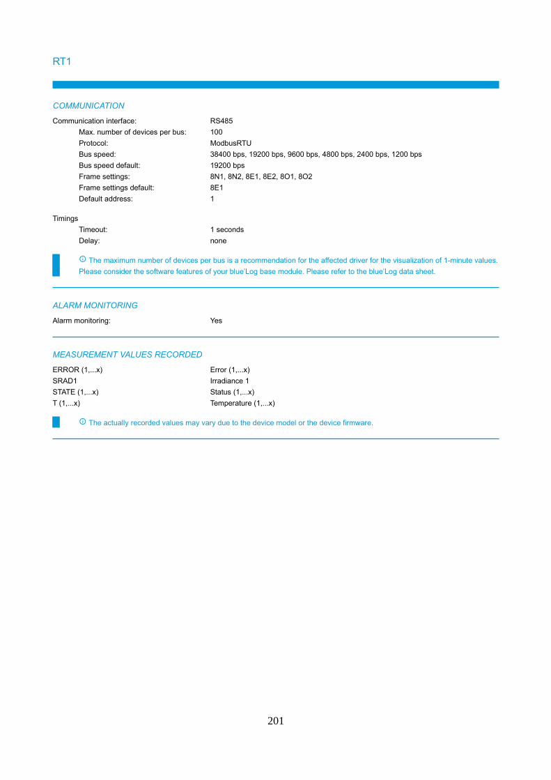
RT1
COMMUNICATION
Communication interface: RS485
Max. number of devices per bus: 100
Protocol: ModbusRTU
Bus speed: 38400 bps, 19200 bps, 9600 bps, 4800 bps, 2400 bps, 1200 bps
Bus speed default: 19200 bps
Frame settings: 8N1, 8N2, 8E1, 8E2, 8O1, 8O2
Frame settings default: 8E1
Default address: 1
Timings
Timeout: 1 seconds
Delay: none
The maximum number of devices per bus is a recommendation for the affected driver for the visualization of 1-minute values.
Please consider the software features of your blue’Log base module. Please refer to the blue’Log data sheet.
ALARM MONITORING
Alarm monitoring: Yes
MEASUREMENT VALUES RECORDED
ERROR (1,...x) Error (1,...x)
SRAD1 Irradiance 1
STATE (1,...x) Status (1,...x)
T (1,...x) Temperature (1,...x)
The actually recorded values may vary due to the device model or the device firmware.
201
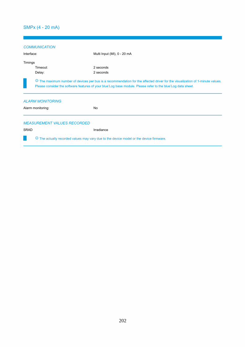
SMPx (4 - 20 mA)
COMMUNICATION
Interface: Multi Input (MI), 0 - 20 mA
Timings
Timeout: 2 seconds
Delay: 2 seconds
The maximum number of devices per bus is a recommendation for the affected driver for the visualization of 1-minute values.
Please consider the software features of your blue’Log base module. Please refer to the blue’Log data sheet.
ALARM MONITORING
Alarm monitoring: No
MEASUREMENT VALUES RECORDED
SRAD Irradiance
The actually recorded values may vary due to the device model or the device firmware.
202
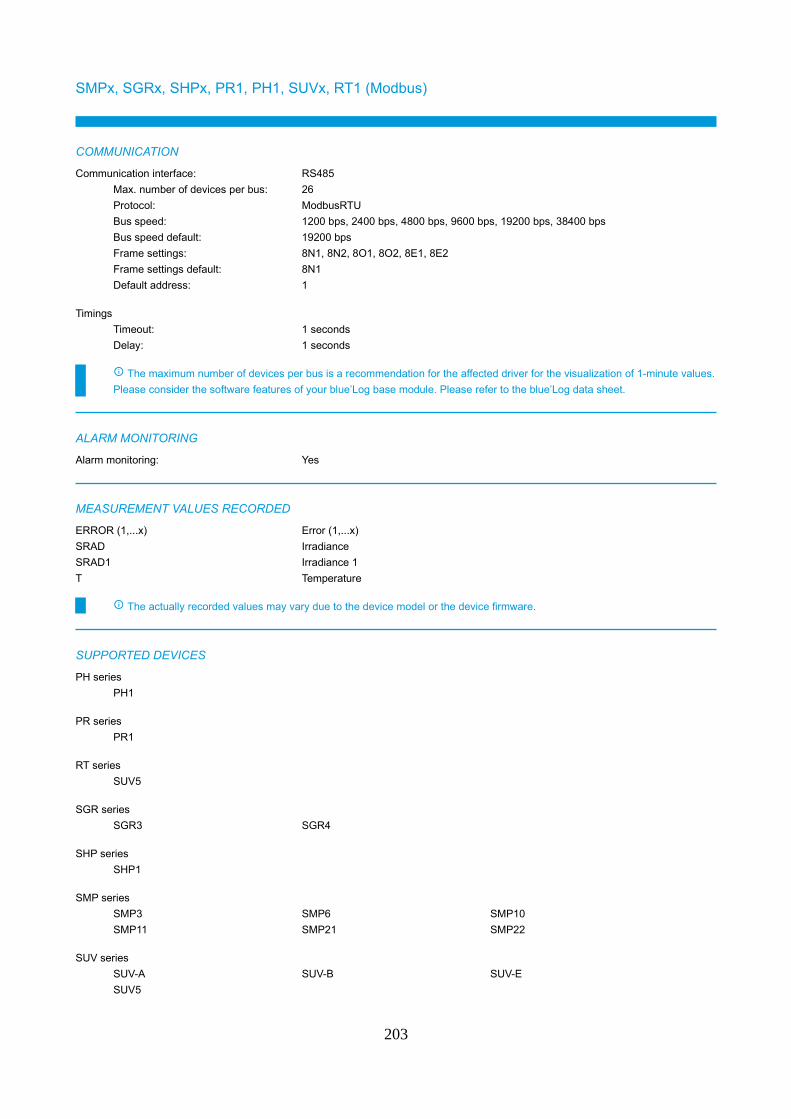
SMPx, SGRx, SHPx, PR1, PH1, SUVx, RT1 (Modbus)
COMMUNICATION
Communication interface: RS485
Max. number of devices per bus: 26
Protocol: ModbusRTU
Bus speed: 1200 bps, 2400 bps, 4800 bps, 9600 bps, 19200 bps, 38400 bps
Bus speed default: 19200 bps
Frame settings: 8N1, 8N2, 8O1, 8O2, 8E1, 8E2
Frame settings default: 8N1
Default address: 1
Timings
Timeout: 1 seconds
Delay: 1 seconds
The maximum number of devices per bus is a recommendation for the affected driver for the visualization of 1-minute values.
Please consider the software features of your blue’Log base module. Please refer to the blue’Log data sheet.
ALARM MONITORING
Alarm monitoring: Yes
MEASUREMENT VALUES RECORDED
ERROR (1,...x) Error (1,...x)
SRAD Irradiance
SRAD1 Irradiance 1
T Temperature
The actually recorded values may vary due to the device model or the device firmware.
SUPPORTED DEVICES
PH series
PH1
PR series
PR1
RT series
SUV5
SGR series
SGR3 SGR4
SHP series
SHP1
SMP series
SMP3 SMP6 SMP10
SMP11 SMP21 SMP22
SUV series
SUV-A SUV-B SUV-E
SUV5
203

Please contact Sales for details of compatibility with devices not listed.
Phone: +49 (0)821 34666 - 80
E-mail: [email protected]
204
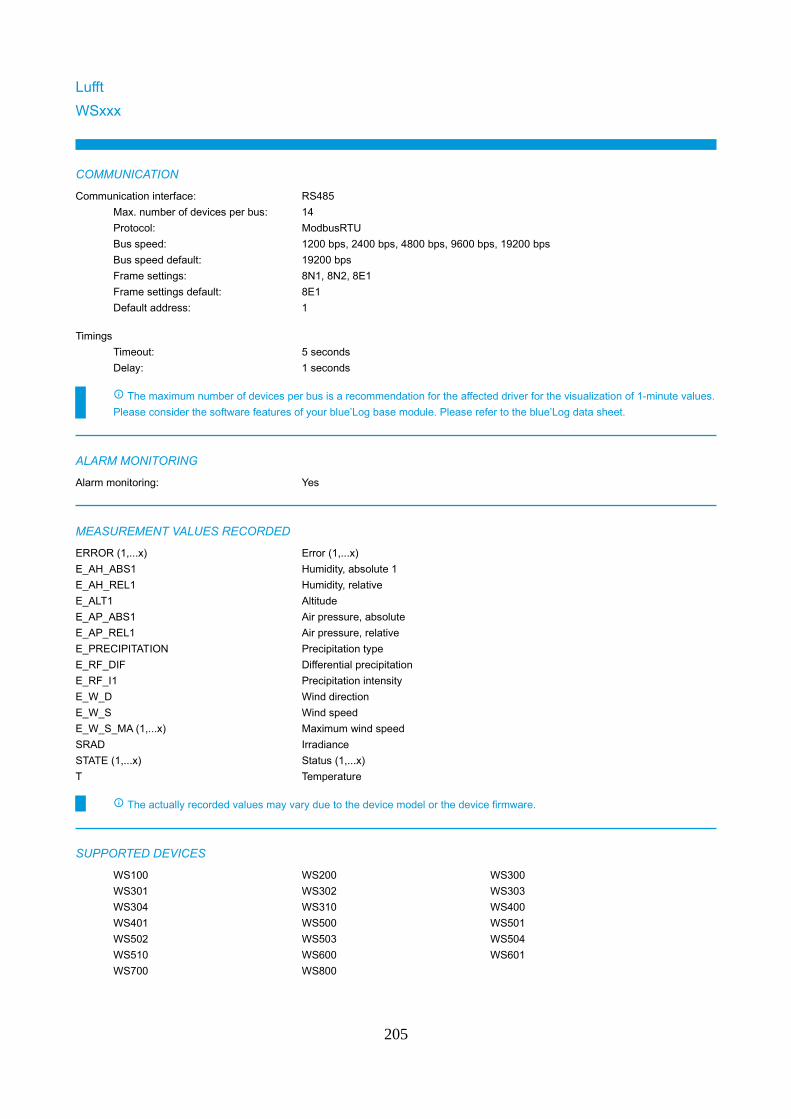
Lufft
WSxxx
COMMUNICATION
Communication interface: RS485
Max. number of devices per bus: 14
Protocol: ModbusRTU
Bus speed: 1200 bps, 2400 bps, 4800 bps, 9600 bps, 19200 bps
Bus speed default: 19200 bps
Frame settings: 8N1, 8N2, 8E1
Frame settings default: 8E1
Default address: 1
Timings
Timeout: 5 seconds
Delay: 1 seconds
The maximum number of devices per bus is a recommendation for the affected driver for the visualization of 1-minute values.
Please consider the software features of your blue’Log base module. Please refer to the blue’Log data sheet.
ALARM MONITORING
Alarm monitoring: Yes
MEASUREMENT VALUES RECORDED
ERROR (1,...x) Error (1,...x)
E_AH_ABS1 Humidity, absolute 1
E_AH_REL1 Humidity, relative
E_ALT1 Altitude
E_AP_ABS1 Air pressure, absolute
E_AP_REL1 Air pressure, relative
E_PRECIPITATION Precipitation type
E_RF_DIF Differential precipitation
E_RF_I1 Precipitation intensity
E_W_D Wind direction
E_W_S Wind speed
E_W_S_MA (1,...x) Maximum wind speed
SRAD Irradiance
STATE (1,...x) Status (1,...x)
T Temperature
The actually recorded values may vary due to the device model or the device firmware.
SUPPORTED DEVICES
WS100 WS200 WS300
WS301 WS302 WS303
WS304 WS310 WS400
WS401 WS500 WS501
WS502 WS503 WS504
WS510 WS600 WS601
WS700 WS800
205

Please contact Sales for details of compatibility with devices not listed.
Phone: +49 (0)821 34666 - 80
E-mail: [email protected]
206
meteocontrol
Hygro-Thermosensor compact
COMMUNICATION
Interface (E_AH_REL1): Multi Input (MI), 0 - 20 mA
Interface (T): Multi Input (MI), 0 - 20 mA
Timings
Timeout: 2 seconds
Delay: 2 seconds
The maximum number of devices per bus is a recommendation for the affected driver for the visualization of 1-minute values.
Please consider the software features of your blue’Log base module. Please refer to the blue’Log data sheet.
ALARM MONITORING
Alarm monitoring: No
MEASUREMENT VALUES RECORDED
E_AH_REL1 Humidity, relative
T Temperature
The actually recorded values may vary due to the device model or the device firmware.
207

PT100 compact
COMMUNICATION
Interface: Multi Input (MI), 0 - 10 V
Timings
Timeout: 2 seconds
Delay: 2 seconds
The maximum number of devices per bus is a recommendation for the affected driver for the visualization of 1-minute values.
Please consider the software features of your blue’Log base module. Please refer to the blue’Log data sheet.
ALARM MONITORING
Alarm monitoring: No
MEASUREMENT VALUES RECORDED
T Temperature
The actually recorded values may vary due to the device model or the device firmware.
208

Si-12TC
COMMUNICATION
Interface: Multi Input (MI), 0 - 10 V
Timings
Timeout: 2 seconds
Delay: 2 seconds
The maximum number of devices per bus is a recommendation for the affected driver for the visualization of 1-minute values.
Please consider the software features of your blue’Log base module. Please refer to the blue’Log data sheet.
ALARM MONITORING
Alarm monitoring: No
MEASUREMENT VALUES RECORDED
SRAD Irradiance
The actually recorded values may vary due to the device model or the device firmware.
209

Si-12TC-T
COMMUNICATION
Interface (SRAD): Multi Input (MI), 0 - 10 V
Interface (T): Multi Input (MI), 0 - 10 V
Timings
Timeout: 2 seconds
Delay: 2 seconds
The maximum number of devices per bus is a recommendation for the affected driver for the visualization of 1-minute values.
Please consider the software features of your blue’Log base module. Please refer to the blue’Log data sheet.
ALARM MONITORING
Alarm monitoring: No
MEASUREMENT VALUES RECORDED
SRAD Irradiance
T Temperature
The actually recorded values may vary due to the device model or the device firmware.
210

Si-020TC
COMMUNICATION
Interface: Multi Input (MI), 0 - 20 mA
Timings
Timeout: 2 seconds
Delay: 2 seconds
The maximum number of devices per bus is a recommendation for the affected driver for the visualization of 1-minute values.
Please consider the software features of your blue’Log base module. Please refer to the blue’Log data sheet.
ALARM MONITORING
Alarm monitoring: No
MEASUREMENT VALUES RECORDED
SRAD Irradiance
The actually recorded values may vary due to the device model or the device firmware.
211

Si-020TC-T
COMMUNICATION
Interface (SRAD): Multi Input (MI), 0 - 20 mA
Interface (T): Multi Input (MI), 0 - 20 mA
Timings
Timeout: 2 seconds
Delay: 2 seconds
The maximum number of devices per bus is a recommendation for the affected driver for the visualization of 1-minute values.
Please consider the software features of your blue’Log base module. Please refer to the blue’Log data sheet.
ALARM MONITORING
Alarm monitoring: No
MEASUREMENT VALUES RECORDED
SRAD Irradiance
T Temperature
The actually recorded values may vary due to the device model or the device firmware.
212

Si-420TC
COMMUNICATION
Interface: Multi Input (MI), 0 - 20 mA
Timings
Timeout: 2 seconds
Delay: 2 seconds
The maximum number of devices per bus is a recommendation for the affected driver for the visualization of 1-minute values.
Please consider the software features of your blue’Log base module. Please refer to the blue’Log data sheet.
ALARM MONITORING
Alarm monitoring: No
MEASUREMENT VALUES RECORDED
SRAD Irradiance
The actually recorded values may vary due to the device model or the device firmware.
213

Si-420TC-T
COMMUNICATION
Interface (SRAD): Multi Input (MI), 0 - 20 mA
Interface (T): Multi Input (MI), 0 - 20 mA
Timings
Timeout: 2 seconds
Delay: 2 seconds
The maximum number of devices per bus is a recommendation for the affected driver for the visualization of 1-minute values.
Please consider the software features of your blue’Log base module. Please refer to the blue’Log data sheet.
ALARM MONITORING
Alarm monitoring: No
MEASUREMENT VALUES RECORDED
SRAD Irradiance
T Temperature
The actually recorded values may vary due to the device model or the device firmware.
214

Si-I-420
COMMUNICATION
Interface: Multi Input (MI), 0 - 20 mA
Timings
Timeout: 2 seconds
Delay: 2 seconds
The maximum number of devices per bus is a recommendation for the affected driver for the visualization of 1-minute values.
Please consider the software features of your blue’Log base module. Please refer to the blue’Log data sheet.
ALARM MONITORING
Alarm monitoring: No
MEASUREMENT VALUES RECORDED
SRAD Irradiance
The actually recorded values may vary due to the device model or the device firmware.
215
Si-I-420-T
COMMUNICATION
Interface (SRAD): Multi Input (MI), 0 - 20 mA
Interface (T): Multi Input (MI), 0 - 20 mA
Timings
Timeout: 2 seconds
Delay: 2 seconds
The maximum number of devices per bus is a recommendation for the affected driver for the visualization of 1-minute values.
Please consider the software features of your blue’Log base module. Please refer to the blue’Log data sheet.
ALARM MONITORING
Alarm monitoring: No
MEASUREMENT VALUES RECORDED
SRAD Irradiance
T Temperature
The actually recorded values may vary due to the device model or the device firmware.
216
Si-RS485TC-2T-MB
COMMUNICATION
Communication interface: RS485
Max. number of devices per bus: 27
Protocol: ModbusRTU
Bus speed: 9600 bps, 19200 bps, 38400 bps
Bus speed default: 19200 bps
Frame settings: 8N1, 8E1
Frame settings default: 8N1
Default address: 1
Timings
Timeout: 2 seconds
Delay: 1 seconds
The maximum number of devices per bus is a recommendation for the affected driver for the visualization of 1-minute values.
Please consider the software features of your blue’Log base module. Please refer to the blue’Log data sheet.
ALARM MONITORING
Alarm monitoring: No
MEASUREMENT VALUES RECORDED
SRAD Irradiance
T (1,...x) Temperature (1,...x)
The actually recorded values may vary due to the device model or the device firmware.
Temperature 1 = Module temperature (internal measurement)
Temperature 2 = Ambient temperature
217
Si-RS485TC-2T-V-MBBeta version (see chapter „Beta version“)
COMMUNICATION
Communication interface: RS485
Max. number of devices per bus: 27
Protocol: ModbusRTU
Bus speed: 9600 bps, 19200 bps, 38400 bps
Bus speed default: 19200 bps
Frame settings: 8N1, 8E1
Frame settings default: 8N1
Default address: 1
Timings
Timeout: 2 seconds
Delay: 1 seconds
The maximum number of devices per bus is a recommendation for the affected driver for the visualization of 1-minute values.
Please consider the software features of your blue’Log base module. Please refer to the blue’Log data sheet.
ALARM MONITORING
Alarm monitoring: No
MEASUREMENT VALUES RECORDED
E_W_S Wind speed
SRAD Irradiance
T (1,...x) Temperature (1,...x)
The actually recorded values may vary due to the device model or the device firmware.
Temperature 1 = Module temperature (internal measurement)
Temperature 2 = Ambient temperature
218
Si-RS485TC-T-MB
COMMUNICATION
Communication interface: RS485
Max. number of devices per bus: 27
Protocol: ModbusRTU
Bus speed: 9600 bps, 19200 bps, 38400 bps
Bus speed default: 19200 bps
Frame settings: 8N1, 8E1
Frame settings default: 8N1
Default address: 1
Timings
Timeout: 2 seconds
Delay: 1 seconds
The maximum number of devices per bus is a recommendation for the affected driver for the visualization of 1-minute values.
Please consider the software features of your blue’Log base module. Please refer to the blue’Log data sheet.
ALARM MONITORING
Alarm monitoring: No
MEASUREMENT VALUES RECORDED
SRAD Irradiance
T Temperature
The actually recorded values may vary due to the device model or the device firmware.
219

Si-RS485TC-T-Tm-MB
COMMUNICATION
Communication interface: RS485
Max. number of devices per bus: 27
Protocol: ModbusRTU
Bus speed: 9600 bps, 19200 bps, 38400 bps
Bus speed default: 19200 bps
Frame settings: 8N1, 8E1
Frame settings default: 8N1
Default address: 1
Timings
Timeout: 2 seconds
Delay: 1 seconds
The maximum number of devices per bus is a recommendation for the affected driver for the visualization of 1-minute values.
Please consider the software features of your blue’Log base module. Please refer to the blue’Log data sheet.
ALARM MONITORING
Alarm monitoring: No
MEASUREMENT VALUES RECORDED
SRAD Irradiance
T (1,...x) Temperature (1,...x)
The actually recorded values may vary due to the device model or the device firmware.
Temperature 1 = Module temperature (internal measurement)
Temperature 2 = Ambient temperature
220

Si-V-010
COMMUNICATION
Interface: Multi Input (MI), 0 - 10 V
Timings
Timeout: 2 seconds
Delay: 2 seconds
The maximum number of devices per bus is a recommendation for the affected driver for the visualization of 1-minute values.
Please consider the software features of your blue’Log base module. Please refer to the blue’Log data sheet.
ALARM MONITORING
Alarm monitoring: No
MEASUREMENT VALUES RECORDED
SRAD Irradiance
The actually recorded values may vary due to the device model or the device firmware.
221

Si-V-010-T
COMMUNICATION
Interface (SRAD): Multi Input (MI), 0 - 10 V
Interface (T): Multi Input (MI), 0 - 10 V
Timings
Timeout: 2 seconds
Delay: 2 seconds
The maximum number of devices per bus is a recommendation for the affected driver for the visualization of 1-minute values.
Please consider the software features of your blue’Log base module. Please refer to the blue’Log data sheet.
ALARM MONITORING
Alarm monitoring: No
MEASUREMENT VALUES RECORDED
SRAD Irradiance
T Temperature
The actually recorded values may vary due to the device model or the device firmware.
222
Ta-ext-RS485
COMMUNICATION
Communication interface: RS485
Max. number of devices per bus: 27
Protocol: ModbusRTU
Bus speed: 1200 bps, 2400 bps, 9600 bps, 19200 bps, 38400 bps
Bus speed default: 19200 bps
Frame settings: 8N1, 8E1, 8O1, 8N2
Frame settings default: 8N1
Default address: 1
Timings
Timeout: 2 seconds
Delay: 1 seconds
The maximum number of devices per bus is a recommendation for the affected driver for the visualization of 1-minute values.
Please consider the software features of your blue’Log base module. Please refer to the blue’Log data sheet.
ALARM MONITORING
Alarm monitoring: No
MEASUREMENT VALUES RECORDED
T Temperature
The actually recorded values may vary due to the device model or the device firmware.
223

Tm-I-4090
COMMUNICATION
Interface: Multi Input (MI), 0 - 20 mA
Timings
Timeout: 2 seconds
Delay: 2 seconds
The maximum number of devices per bus is a recommendation for the affected driver for the visualization of 1-minute values.
Please consider the software features of your blue’Log base module. Please refer to the blue’Log data sheet.
ALARM MONITORING
Alarm monitoring: No
MEASUREMENT VALUES RECORDED
T Temperature
The actually recorded values may vary due to the device model or the device firmware.
224
Tm-RS485
COMMUNICATION
Communication interface: RS485
Max. number of devices per bus: 27
Protocol: ModbusRTU
Bus speed: 1200 bps, 2400 bps, 9600 bps, 19200 bps, 38400 bps
Bus speed default: 19200 bps
Frame settings: 8N1, 8E1, 8O1, 8N2
Frame settings default: 8N1
Default address: 1
Timings
Timeout: 2 seconds
Delay: 1 seconds
The maximum number of devices per bus is a recommendation for the affected driver for the visualization of 1-minute values.
Please consider the software features of your blue’Log base module. Please refer to the blue’Log data sheet.
ALARM MONITORING
Alarm monitoring: No
MEASUREMENT VALUES RECORDED
T Temperature
The actually recorded values may vary due to the device model or the device firmware.
225
Wind direction classic (0 - 10 V)
COMMUNICATION
Interface: Multi Input (MI), 0 - 10 V
Timings
Timeout: 2 seconds
Delay: 2 seconds
The maximum number of devices per bus is a recommendation for the affected driver for the visualization of 1-minute values.
Please consider the software features of your blue’Log base module. Please refer to the blue’Log data sheet.
ALARM MONITORING
Alarm monitoring: No
MEASUREMENT VALUES RECORDED
E_W_D Wind direction
The actually recorded values may vary due to the device model or the device firmware.
226

Wind direction classic (4 - 20 mA)
COMMUNICATION
Interface: Multi Input (MI), 0 - 20 mA
Timings
Timeout: 2 seconds
Delay: 2 seconds
The maximum number of devices per bus is a recommendation for the affected driver for the visualization of 1-minute values.
Please consider the software features of your blue’Log base module. Please refer to the blue’Log data sheet.
ALARM MONITORING
Alarm monitoring: No
MEASUREMENT VALUES RECORDED
E_W_D Wind direction
The actually recorded values may vary due to the device model or the device firmware.
227

Wind direction compact (0 - 10 V)
COMMUNICATION
Interface: Multi Input (MI), 0 - 10 V
Timings
Timeout: 2 seconds
Delay: 2 seconds
The maximum number of devices per bus is a recommendation for the affected driver for the visualization of 1-minute values.
Please consider the software features of your blue’Log base module. Please refer to the blue’Log data sheet.
ALARM MONITORING
Alarm monitoring: No
MEASUREMENT VALUES RECORDED
E_W_D Wind direction
The actually recorded values may vary due to the device model or the device firmware.
228

Wind direction compact (4 - 20 mA)
COMMUNICATION
Interface: Multi Input (MI), 0 - 20 mA
Timings
Timeout: 2 seconds
Delay: 2 seconds
The maximum number of devices per bus is a recommendation for the affected driver for the visualization of 1-minute values.
Please consider the software features of your blue’Log base module. Please refer to the blue’Log data sheet.
ALARM MONITORING
Alarm monitoring: No
MEASUREMENT VALUES RECORDED
E_W_D Wind direction
The actually recorded values may vary due to the device model or the device firmware.
229

Wind speed classic (0 - 10 V)
COMMUNICATION
Interface: Multi Input (MI), 0 - 10 V
Timings
Timeout: 2 seconds
Delay: 2 seconds
The maximum number of devices per bus is a recommendation for the affected driver for the visualization of 1-minute values.
Please consider the software features of your blue’Log base module. Please refer to the blue’Log data sheet.
ALARM MONITORING
Alarm monitoring: No
MEASUREMENT VALUES RECORDED
E_W_S Wind speed
The actually recorded values may vary due to the device model or the device firmware.
230

Wind speed classic (4 - 20 mA)
COMMUNICATION
Interface: Multi Input (MI), 0 - 20 mA
Timings
Timeout: 2 seconds
Delay: 2 seconds
The maximum number of devices per bus is a recommendation for the affected driver for the visualization of 1-minute values.
Please consider the software features of your blue’Log base module. Please refer to the blue’Log data sheet.
ALARM MONITORING
Alarm monitoring: No
MEASUREMENT VALUES RECORDED
E_W_S Wind speed
The actually recorded values may vary due to the device model or the device firmware.
231

Wind speed compact (0 - 10 V)
COMMUNICATION
Interface: Multi Input (MI), 0 - 10 V
Timings
Timeout: 2 seconds
Delay: 2 seconds
The maximum number of devices per bus is a recommendation for the affected driver for the visualization of 1-minute values.
Please consider the software features of your blue’Log base module. Please refer to the blue’Log data sheet.
ALARM MONITORING
Alarm monitoring: No
MEASUREMENT VALUES RECORDED
E_W_S Wind speed
The actually recorded values may vary due to the device model or the device firmware.
232

Wind speed compact (4 - 20 mA)
COMMUNICATION
Interface: Multi Input (MI), 0 - 20 mA
Timings
Timeout: 2 seconds
Delay: 2 seconds
The maximum number of devices per bus is a recommendation for the affected driver for the visualization of 1-minute values.
Please consider the software features of your blue’Log base module. Please refer to the blue’Log data sheet.
ALARM MONITORING
Alarm monitoring: No
MEASUREMENT VALUES RECORDED
E_W_S Wind speed
The actually recorded values may vary due to the device model or the device firmware.
233

NES
SOZ-03
COMMUNICATION
Interface: Multi Input (MI), 0 - 1 V
Timings
Timeout: 2 seconds
Delay: 2 seconds
The maximum number of devices per bus is a recommendation for the affected driver for the visualization of 1-minute values.
Please consider the software features of your blue’Log base module. Please refer to the blue’Log data sheet.
ALARM MONITORING
Alarm monitoring: No
MEASUREMENT VALUES RECORDED
SRAD Irradiance
The actually recorded values may vary due to the device model or the device firmware.
234
Power Electronics
Protection system - HEMK + MVSKIDBeta version (see chapter „Beta version“)
COMMUNICATION
Communication interface: Ethernet
Max. number of devices: 100
Protocol: ModbusTCP
Port: 502
Default address: 1
Timings
Timeout: 5 seconds
Delay: none
The maximum number of devices per bus is a recommendation for the affected driver for the visualization of 1-minute values.
Please consider the software features of your blue’Log base module. Please refer to the blue’Log data sheet.
ALARM MONITORING
Alarm monitoring: Yes
MEASUREMENT VALUES RECORDED
ERROR (1,...x) Error (1,...x)
STATE (1,...x) Status (1,...x)
T (1,...x) Temperature (1,...x)
The actually recorded values may vary due to the device model or the device firmware.
235

Sommer Messtechnik
USH-8/9 (0 - 20 mA)
COMMUNICATION
Interface: Multi Input (MI), 0 - 20 mA
Timings
Timeout: 2 seconds
Delay: 2 seconds
The maximum number of devices per bus is a recommendation for the affected driver for the visualization of 1-minute values.
Please consider the software features of your blue’Log base module. Please refer to the blue’Log data sheet.
ALARM MONITORING
Alarm monitoring: No
MEASUREMENT VALUES RECORDED
E_SNOW_DEPTH Snow depth
The actually recorded values may vary due to the device model or the device firmware.
236
USH-8/9 (4 - 20 mA)
COMMUNICATION
Interface: Multi Input (MI), 0 - 20 mA
Timings
Timeout: 2 seconds
Delay: 2 seconds
The maximum number of devices per bus is a recommendation for the affected driver for the visualization of 1-minute values.
Please consider the software features of your blue’Log base module. Please refer to the blue’Log data sheet.
ALARM MONITORING
Alarm monitoring: No
MEASUREMENT VALUES RECORDED
E_SNOW_DEPTH Snow depth
The actually recorded values may vary due to the device model or the device firmware.
237
USH-9 (Modbus)
COMMUNICATION
Communication interface: RS485
Max. number of devices per bus: 100
Protocol: ModbusRTU
Bus speed: 1200 bps, 2400 bps, 4800 bps, 9600 bps, 19200 bps, 38400 bps, 57600 bps,
115200 bps
Bus speed default: 9600 bps
Frame settings: 8E1, 8N1, 8N2, 8O1
Frame settings default: 8N1
Default address: 35
Timings
Timeout: 2 seconds
Delay: none
The maximum number of devices per bus is a recommendation for the affected driver for the visualization of 1-minute values.
Please consider the software features of your blue’Log base module. Please refer to the blue’Log data sheet.
ALARM MONITORING
Alarm monitoring: Yes
MEASUREMENT VALUES RECORDED
ERROR (1,...x) Error (1,...x)
E_SNOW_DEPTH Snow depth
T Temperature
The actually recorded values may vary due to the device model or the device firmware.
238

SunSpec Alliance
Compatible sensor
COMMUNICATION
Communication interface: Ethernet
Max. number of devices: 100
Protocol: ModbusTCP
Port: 502
Default address: 1
Communication interface: RS485
Max. number of devices per bus: 96
Protocol: ModbusRTU
Bus speed: 9600 bps, 19200 bps, 38400 bps, 57600 bps, 115200 bps
Bus speed default: 9600 bps
Frame settings: 8N1
Frame settings default: 8N1
Default address: 1
Timings
Timeout: 1 seconds
Delay: none
The maximum number of devices per bus is a recommendation for the affected driver for the visualization of 1-minute values.
Please consider the software features of your blue’Log base module. Please refer to the blue’Log data sheet.
ALARM MONITORING
Alarm monitoring: No
MEASUREMENT VALUES RECORDED
Model 302 Model 303 Model 305
Model 307 Model 308
The actually recorded values may vary due to the device model or the device firmware.
239
Thermokon
PT1000 with integrated converter
COMMUNICATION
Interface: Multi Input (MI), 0 - 10 V
Timings
Timeout: 2 seconds
Delay: 2 seconds
The maximum number of devices per bus is a recommendation for the affected driver for the visualization of 1-minute values.
Please consider the software features of your blue’Log base module. Please refer to the blue’Log data sheet.
ALARM MONITORING
Alarm monitoring: No
MEASUREMENT VALUES RECORDED
T Temperature
The actually recorded values may vary due to the device model or the device firmware.
240
Vendor-neutral
PT1000
COMMUNICATION
Interface: Multi Input (MI), 0 - 10 Ohm
Timings
Timeout: 2 seconds
Delay: 2 seconds
The maximum number of devices per bus is a recommendation for the affected driver for the visualization of 1-minute values.
Please consider the software features of your blue’Log base module. Please refer to the blue’Log data sheet.
ALARM MONITORING
Alarm monitoring: No
MEASUREMENT VALUES RECORDED
T Temperature
The actually recorded values may vary due to the device model or the device firmware.
241
MeterABB
A43/A44
COMMUNICATION
Communication interface: RS485
Max. number of devices per bus: 99
Protocol: ModbusRTU
Bus speed: 1200 bps, 2400 bps, 4800 bps, 9600 bps, 19200 bps, 38400 bps, 57600 bps,
115200 bps
Bus speed default: 19200 bps
Frame settings: 8N1, 8E1, 8O1
Frame settings default: 8E1
Default address: 1
Timings
Timeout: 1 seconds
Delay: none
The maximum number of devices per bus is a recommendation for the affected driver for the visualization of 1-minute values.
Please consider the software features of your blue’Log base module. Please refer to the blue’Log data sheet.
POWER CONTROL
For use of Power Control: Yes
For use of control criterion phase-related: Yes
Compliance with Grid Code specific requirements using this measuring instrument cannot be guaranteed in general, but has
to be checked on a project-specific basis.
ALARM MONITORING
Alarm monitoring: Yes
242
MEASUREMENT VALUES RECORDED
D_IN (1,...x) Digital input (1,...x)
ERROR (1,...x) Error (1,...x)
M_AC_ES_EXP Apparent energy (exported)
M_AC_ES_IMP Apparent energy (imported)
M_AC_E_EXP Active energy (export)
M_AC_E_IMP Active energy (import)
M_AC_F Grid frequency
M_AC_I1 Current AC phase 1
M_AC_I2 Current AC phase 2
M_AC_I3 Current AC phase 3
M_AC_I_N Current, neutral conductor
M_AC_P Power AC
M_AC_P1 Power AC phase 1
M_AC_P2 Power AC phase 2
M_AC_P3 Power AC phase 3
M_AC_PF_COSPHI Power factor (cos phi)
M_AC_PF_COSPHI1 Power factor (cos phi) phase 1
M_AC_PF_COSPHI2 Power factor (cos phi) phase 2
M_AC_PF_COSPHI3 Power factor (cos phi) phase 3
M_AC_Q Reactive power
M_AC_Q1 Reactive power, phase 1
M_AC_Q2 Reactive power, phase 2
M_AC_Q3 Reactive power, phase 3
M_AC_S Apparent power
M_AC_S1 Apparent power phase 1
M_AC_S2 Apparent power phase 2
M_AC_S3 Apparent power phase 3
M_AC_U1 Voltage AC phase 1
M_AC_U2 Voltage AC phase 2
M_AC_U3 Voltage AC phase 3
M_AC_U_L1L2 Phase voltage L1L2
M_AC_U_L2L3 Phase voltage L2L3
M_AC_U_L3L1 Phase voltage L3L1
STATE (1,...x) Status (1,...x)
The actually recorded values may vary due to the device model or the device firmware.
SUPPORTED DEVICES
A43 A44
Please contact Sales for details of compatibility with devices not listed.
Phone: +49 (0)821 34666 - 80
E-mail: [email protected]
243
B23/B24Beta version (see chapter „Beta version“)
COMMUNICATION
Communication interface: RS485
Max. number of devices per bus: 94
Protocol: ModbusRTU
Bus speed: 1200 bps, 2400 bps, 4800 bps, 9600 bps, 19200 bps, 38400 bps, 57600 bps,
115200 bps
Bus speed default: 9600 bps
Frame settings: 8N1, 8E1, 8O1
Frame settings default: 8N1
Default address: 1
Timings
Timeout: 1 seconds
Delay: none
The maximum number of devices per bus is a recommendation for the affected driver for the visualization of 1-minute values.
Please consider the software features of your blue’Log base module. Please refer to the blue’Log data sheet.
POWER CONTROL
For use of Power Control: Yes
For use of control criterion phase-related: Yes
Compliance with Grid Code specific requirements using this measuring instrument cannot be guaranteed in general, but has
to be checked on a project-specific basis.
ALARM MONITORING
Alarm monitoring: No
244

MEASUREMENT VALUES RECORDED
M_AC_ES_EXP Apparent energy (exported)
M_AC_ES_IMP Apparent energy (imported)
M_AC_E_EXP Active energy (export)
M_AC_E_IMP Active energy (import)
M_AC_F Grid frequency
M_AC_I1 Current AC phase 1
M_AC_I2 Current AC phase 2
M_AC_I3 Current AC phase 3
M_AC_I_N Current, neutral conductor
M_AC_P Power AC
M_AC_P1 Power AC phase 1
M_AC_P2 Power AC phase 2
M_AC_P3 Power AC phase 3
M_AC_PF_COSPHI Power factor (cos phi)
M_AC_PF_COSPHI1 Power factor (cos phi) phase 1
M_AC_PF_COSPHI2 Power factor (cos phi) phase 2
M_AC_PF_COSPHI3 Power factor (cos phi) phase 3
M_AC_Q Reactive power
M_AC_Q1 Reactive power, phase 1
M_AC_Q2 Reactive power, phase 2
M_AC_Q3 Reactive power, phase 3
M_AC_S Apparent power
M_AC_S1 Apparent power phase 1
M_AC_S2 Apparent power phase 2
M_AC_S3 Apparent power phase 3
M_AC_U1 Voltage AC phase 1
M_AC_U2 Voltage AC phase 2
M_AC_U3 Voltage AC phase 3
M_AC_U_L1L2 Phase voltage L1L2
M_AC_U_L2L3 Phase voltage L2L3
M_AC_U_L3L1 Phase voltage L3L1
The actually recorded values may vary due to the device model or the device firmware.
245
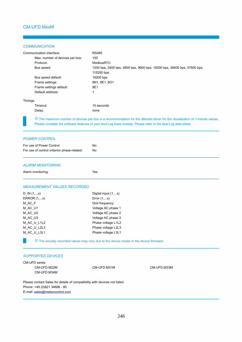
CM-UFD.MxxM
COMMUNICATION
Communication interface: RS485
Max. number of devices per bus: 100
Protocol: ModbusRTU
Bus speed: 1200 bps, 2400 bps, 4800 bps, 9600 bps, 19200 bps, 38400 bps, 57600 bps,
115200 bps
Bus speed default: 19200 bps
Frame settings: 8N1, 8E1, 8O1
Frame settings default: 8E1
Default address: 1
Timings
Timeout: 10 seconds
Delay: none
The maximum number of devices per bus is a recommendation for the affected driver for the visualization of 1-minute values.
Please consider the software features of your blue’Log base module. Please refer to the blue’Log data sheet.
POWER CONTROL
For use of Power Control: No
For use of control criterion phase-related: No
ALARM MONITORING
Alarm monitoring: Yes
MEASUREMENT VALUES RECORDED
D_IN (1,...x) Digital input (1,...x)
ERROR (1,...x) Error (1,...x)
M_AC_F Grid frequency
M_AC_U1 Voltage AC phase 1
M_AC_U2 Voltage AC phase 2
M_AC_U3 Voltage AC phase 3
M_AC_U_L1L2 Phase voltage L1L2
M_AC_U_L2L3 Phase voltage L2L3
M_AC_U_L3L1 Phase voltage L3L1
The actually recorded values may vary due to the device model or the device firmware.
SUPPORTED DEVICES
CM-UFD series
CM-UFD.M22M CM-UFD.M31M CM-UFD.M33M
CM-UFD.M34M
Please contact Sales for details of compatibility with devices not listed.
Phone: +49 (0)821 34666 - 80
E-mail: [email protected]
246
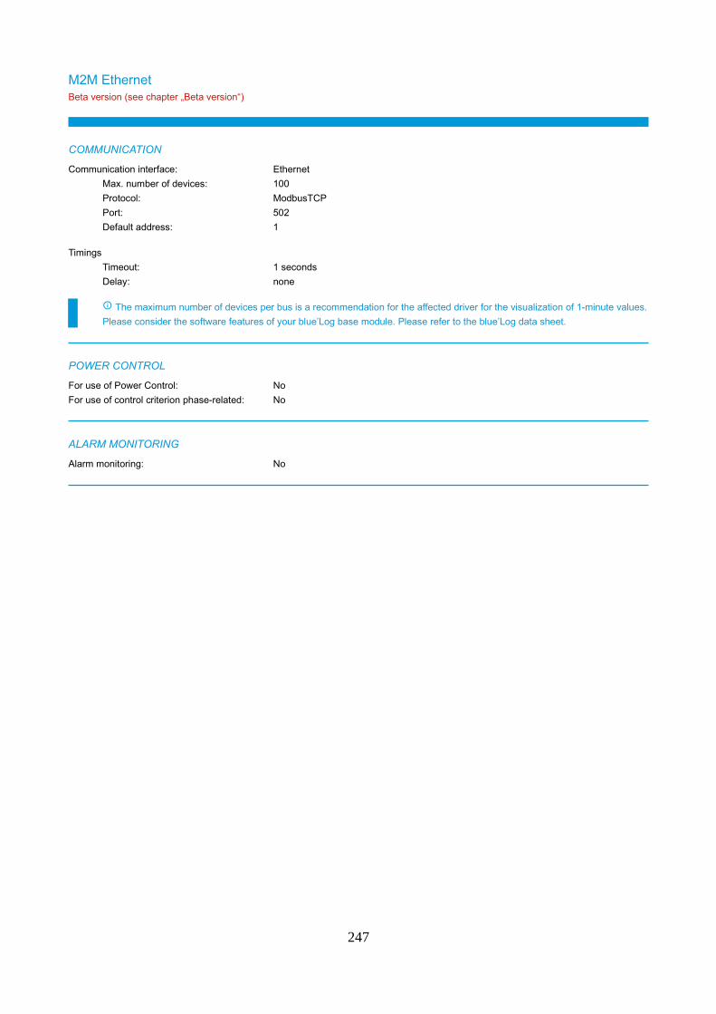
M2M EthernetBeta version (see chapter „Beta version“)
COMMUNICATION
Communication interface: Ethernet
Max. number of devices: 100
Protocol: ModbusTCP
Port: 502
Default address: 1
Timings
Timeout: 1 seconds
Delay: none
The maximum number of devices per bus is a recommendation for the affected driver for the visualization of 1-minute values.
Please consider the software features of your blue’Log base module. Please refer to the blue’Log data sheet.
POWER CONTROL
For use of Power Control: No
For use of control criterion phase-related: No
ALARM MONITORING
Alarm monitoring: No
247
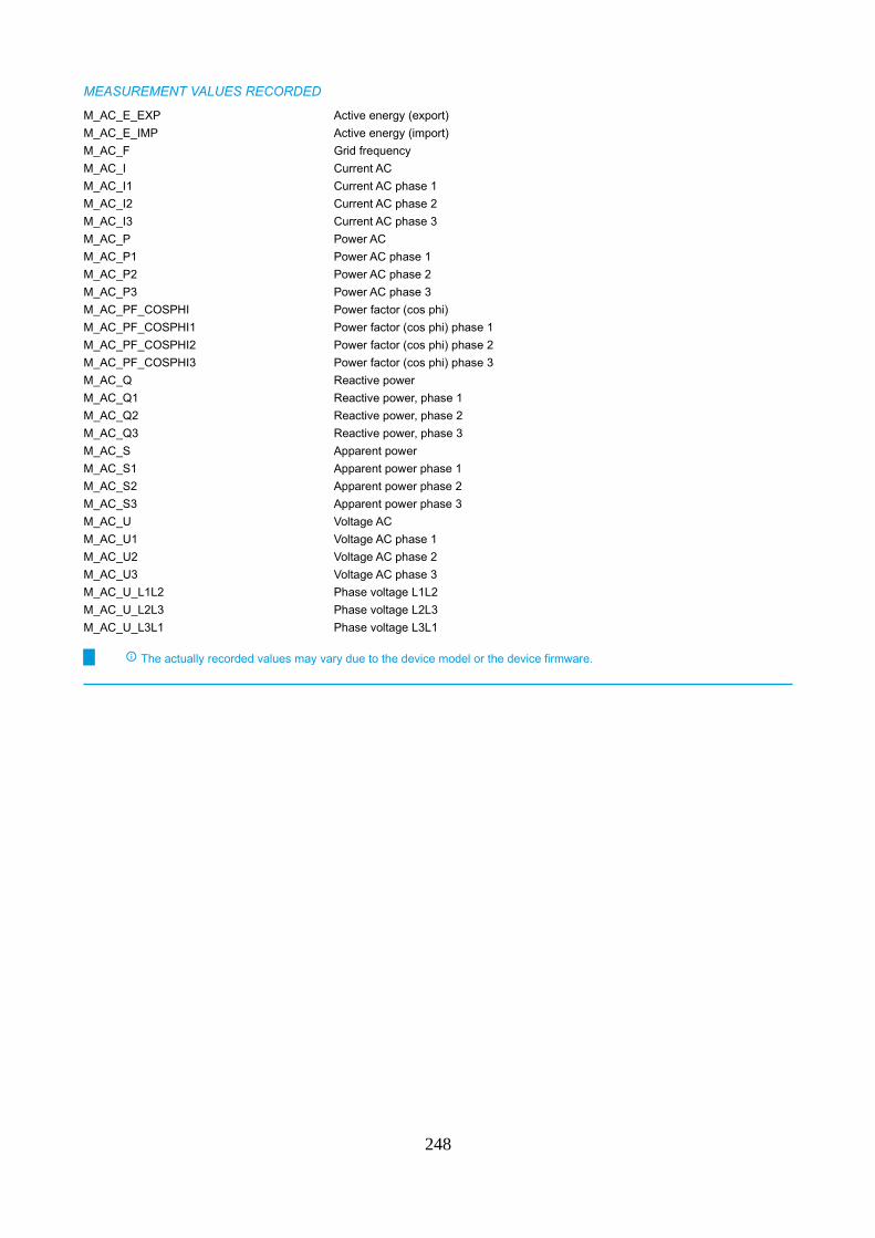
MEASUREMENT VALUES RECORDED
M_AC_E_EXP Active energy (export)
M_AC_E_IMP Active energy (import)
M_AC_F Grid frequency
M_AC_I Current AC
M_AC_I1 Current AC phase 1
M_AC_I2 Current AC phase 2
M_AC_I3 Current AC phase 3
M_AC_P Power AC
M_AC_P1 Power AC phase 1
M_AC_P2 Power AC phase 2
M_AC_P3 Power AC phase 3
M_AC_PF_COSPHI Power factor (cos phi)
M_AC_PF_COSPHI1 Power factor (cos phi) phase 1
M_AC_PF_COSPHI2 Power factor (cos phi) phase 2
M_AC_PF_COSPHI3 Power factor (cos phi) phase 3
M_AC_Q Reactive power
M_AC_Q1 Reactive power, phase 1
M_AC_Q2 Reactive power, phase 2
M_AC_Q3 Reactive power, phase 3
M_AC_S Apparent power
M_AC_S1 Apparent power phase 1
M_AC_S2 Apparent power phase 2
M_AC_S3 Apparent power phase 3
M_AC_U Voltage AC
M_AC_U1 Voltage AC phase 1
M_AC_U2 Voltage AC phase 2
M_AC_U3 Voltage AC phase 3
M_AC_U_L1L2 Phase voltage L1L2
M_AC_U_L2L3 Phase voltage L2L3
M_AC_U_L3L1 Phase voltage L3L1
The actually recorded values may vary due to the device model or the device firmware.
248
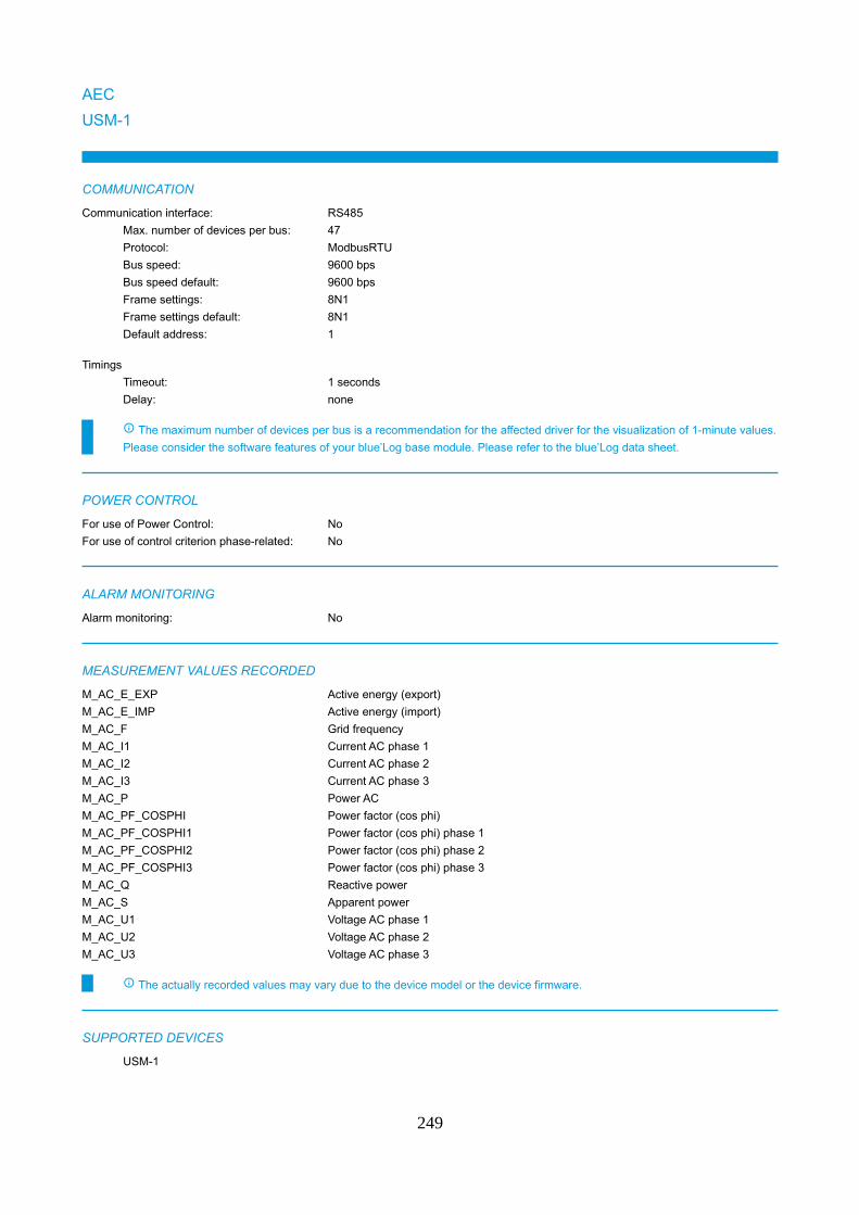
AEC
USM-1
COMMUNICATION
Communication interface: RS485
Max. number of devices per bus: 47
Protocol: ModbusRTU
Bus speed: 9600 bps
Bus speed default: 9600 bps
Frame settings: 8N1
Frame settings default: 8N1
Default address: 1
Timings
Timeout: 1 seconds
Delay: none
The maximum number of devices per bus is a recommendation for the affected driver for the visualization of 1-minute values.
Please consider the software features of your blue’Log base module. Please refer to the blue’Log data sheet.
POWER CONTROL
For use of Power Control: No
For use of control criterion phase-related: No
ALARM MONITORING
Alarm monitoring: No
MEASUREMENT VALUES RECORDED
M_AC_E_EXP Active energy (export)
M_AC_E_IMP Active energy (import)
M_AC_F Grid frequency
M_AC_I1 Current AC phase 1
M_AC_I2 Current AC phase 2
M_AC_I3 Current AC phase 3
M_AC_P Power AC
M_AC_PF_COSPHI Power factor (cos phi)
M_AC_PF_COSPHI1 Power factor (cos phi) phase 1
M_AC_PF_COSPHI2 Power factor (cos phi) phase 2
M_AC_PF_COSPHI3 Power factor (cos phi) phase 3
M_AC_Q Reactive power
M_AC_S Apparent power
M_AC_U1 Voltage AC phase 1
M_AC_U2 Voltage AC phase 2
M_AC_U3 Voltage AC phase 3
The actually recorded values may vary due to the device model or the device firmware.
SUPPORTED DEVICES
USM-1
249

Please contact Sales for details of compatibility with devices not listed.
Phone: +49 (0)821 34666 - 80
E-mail: [email protected]
250
Antarc-Automation
TicMaster (Pro)
COMMUNICATION
Communication interface: Ethernet
Max. number of devices: 100
Protocol: ModbusTCP
Port: 502
Default address: 1
Communication interface: RS485
Max. number of devices per bus: 100
Protocol: ModbusRTU
Bus speed: 1200 bps, 2400 bps, 9600 bps, 19200 bps, 57600 bps
Bus speed default: 9600 bps
Frame settings: 8N1, 8E1, 8O1
Frame settings default: 8N1
Default address: 20
Timings
Timeout: 1 seconds
Delay: none
The maximum number of devices per bus is a recommendation for the affected driver for the visualization of 1-minute values.
Please consider the software features of your blue’Log base module. Please refer to the blue’Log data sheet.
POWER CONTROL
For use of Power Control: No
For use of control criterion phase-related: No
ALARM MONITORING
Alarm monitoring: No
MEASUREMENT VALUES RECORDED
M_AC_E_EXP Active energy (export)
M_AC_E_IMP Active energy (import)
M_AC_I1 Current AC phase 1
M_AC_I2 Current AC phase 2
M_AC_I3 Current AC phase 3
M_AC_PF_COSPHI Power factor (cos phi)
M_AC_U1 Voltage AC phase 1
M_AC_U2 Voltage AC phase 2
M_AC_U3 Voltage AC phase 3
The actually recorded values may vary due to the device model or the device firmware.
SUPPORTED DEVICES
TicMaster series
TicMaster (Pro) Linky TicMaster (Pro) Saphir
251

Please contact Sales for details of compatibility with devices not listed.
Phone: +49 (0)821 34666 - 80
E-mail: [email protected]
252
Bender
LINETRAXX VMD460-NA
COMMUNICATION
Communication interface: RS485
Max. number of devices per bus: 100
Protocol: ModbusRTU
Bus speed: 1200 bps, 2400 bps, 4800 bps, 9600 bps, 19200 bps, 38400 bps, 57600 bps
Bus speed default: 19200 bps
Frame settings: 8N1, 8E1, 8O1
Frame settings default: 8E1
Default address: 2
Timings
Timeout: 1 seconds
Delay: none
The maximum number of devices per bus is a recommendation for the affected driver for the visualization of 1-minute values.
Please consider the software features of your blue’Log base module. Please refer to the blue’Log data sheet.
For communication via Modbus RTU an additional gateway from Bender is needed.
POWER CONTROL
For use of Power Control: No
For use of control criterion phase-related: No
ALARM MONITORING
Alarm monitoring: Yes
MEASUREMENT VALUES RECORDED
ERROR (1,...x) Error (1,...x)
M_AC_F Grid frequency
M_AC_PF_COSPHI Power factor (cos phi)
M_AC_U1 Voltage AC phase 1
M_AC_U2 Voltage AC phase 2
M_AC_U3 Voltage AC phase 3
M_AC_U_L1L2 Phase voltage L1L2
M_AC_U_L2L3 Phase voltage L2L3
M_AC_U_L3L1 Phase voltage L3L1
The actually recorded values may vary due to the device model or the device firmware.
253
CCK
CCK6700E
COMMUNICATION
Communication interface: Ethernet
Max. number of devices: 100
Protocol: ModbusTCP
Port: 502
Default address: 1
Communication interface: RS485
Max. number of devices per bus: 40
Protocol: ModbusRTU
Bus speed: 1200 bps, 2400 bps, 4800 bps, 9600 bps, 19200 bps, 38400 bps, 57600 bps,
115200 bps
Bus speed default: 9600 bps
Frame settings: 7N1, 7O1, 7E1, 7N2, 7O2, 7E2, 8N1, 8E1, 8O1, 8N2, 8E2, 8O2
Frame settings default: 8N1
Default address: 1
Timings
Timeout: 1 seconds
Delay: 0.2 seconds
The maximum number of devices per bus is a recommendation for the affected driver for the visualization of 1-minute values.
Please consider the software features of your blue’Log base module. Please refer to the blue’Log data sheet.
Please note for connection of the CCK6700E via TCP a RS485 to Ethernet converter is required.
POWER CONTROL
For use of Power Control: No
For use of control criterion phase-related: No
ALARM MONITORING
Alarm monitoring: No
254
MEASUREMENT VALUES RECORDED
M_AC_EQ_CAP_EXP Reactive energy (capacitive export)
M_AC_EQ_CAP_EXP_T1 Negative - Reactive Energy capacitive exported (Tariff 1)
M_AC_EQ_CAP_EXP_T2 Negative - Reactive Energy capacitive exported (Tariff 2)
M_AC_EQ_CAP_IMP Reactive energy (capacitive import)
M_AC_EQ_CAP_IMP_T1 Positive - Reactive Energy capacitive imported (Tariff 1)
M_AC_EQ_CAP_IMP_T2 Positive - Reactive Energy capacitive imported (Tariff 2)
M_AC_EQ_IND_EXP Reactive energy (inductive export)
M_AC_EQ_IND_EXP_T1 Positive - Reactive Energy inductive exported (Tariff 1)
M_AC_EQ_IND_EXP_T2 Positive - Reactive Energy inductive exported (Tariff 2)
M_AC_EQ_IND_IMP Reactive energy (inductive import)
M_AC_EQ_IND_IMP_T1 Positive - Reactive Energy inductive imported (Tariff 1)
M_AC_EQ_IND_IMP_T2 Positive - Reactive Energy inductive imported (Tariff 2)
M_AC_E_EXP Active energy (export)
M_AC_E_EXP_T1 Active energy for Tariff 1 (export)
M_AC_E_EXP_T2 Active energy for Tariff 2 (export)
M_AC_E_IMP Active energy (import)
M_AC_E_IMP_T1 Active energy for Tariff 1 (import)
M_AC_E_IMP_T2 Active energy for Tariff 2 (import)
M_AC_E_MONTH_IMP Active energy monthly (import)
M_AC_P_DEMAND_T1 Active Power Demand (Tariff 1)
M_AC_P_DEMAND_T2 Active Power Demand (Tariff 2)
The actually recorded values may vary due to the device model or the device firmware.
255
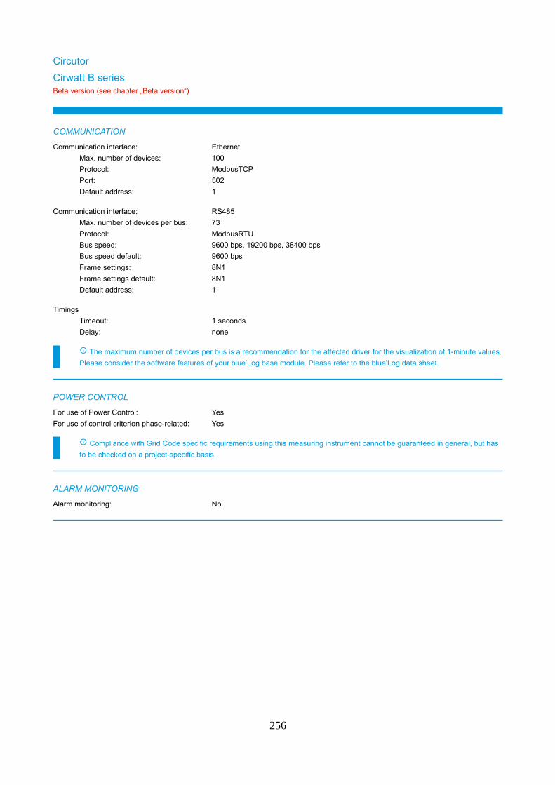
Circutor
Cirwatt B seriesBeta version (see chapter „Beta version“)
COMMUNICATION
Communication interface: Ethernet
Max. number of devices: 100
Protocol: ModbusTCP
Port: 502
Default address: 1
Communication interface: RS485
Max. number of devices per bus: 73
Protocol: ModbusRTU
Bus speed: 9600 bps, 19200 bps, 38400 bps
Bus speed default: 9600 bps
Frame settings: 8N1
Frame settings default: 8N1
Default address: 1
Timings
Timeout: 1 seconds
Delay: none
The maximum number of devices per bus is a recommendation for the affected driver for the visualization of 1-minute values.
Please consider the software features of your blue’Log base module. Please refer to the blue’Log data sheet.
POWER CONTROL
For use of Power Control: Yes
For use of control criterion phase-related: Yes
Compliance with Grid Code specific requirements using this measuring instrument cannot be guaranteed in general, but has
to be checked on a project-specific basis.
ALARM MONITORING
Alarm monitoring: No
256

MEASUREMENT VALUES RECORDED
D_IN (1,...x) Digital input (1,...x)
M_AC_E_EXP Active energy (export)
M_AC_E_IMP Active energy (import)
M_AC_F Grid frequency
M_AC_I1 Current AC phase 1
M_AC_I2 Current AC phase 2
M_AC_I3 Current AC phase 3
M_AC_P Power AC
M_AC_P1 Power AC phase 1
M_AC_P2 Power AC phase 2
M_AC_P3 Power AC phase 3
M_AC_PF_COSPHI Power factor (cos phi)
M_AC_PF_COSPHI1 Power factor (cos phi) phase 1
M_AC_PF_COSPHI2 Power factor (cos phi) phase 2
M_AC_PF_COSPHI3 Power factor (cos phi) phase 3
M_AC_Q Reactive power
M_AC_Q1 Reactive power, phase 1
M_AC_Q2 Reactive power, phase 2
M_AC_Q3 Reactive power, phase 3
M_AC_S Apparent power
M_AC_S1 Apparent power phase 1
M_AC_S2 Apparent power phase 2
M_AC_S3 Apparent power phase 3
M_AC_U1 Voltage AC phase 1
M_AC_U2 Voltage AC phase 2
M_AC_U3 Voltage AC phase 3
M_AC_U_L1L2 Phase voltage L1L2
M_AC_U_L2L3 Phase voltage L2L3
M_AC_U_L3L1 Phase voltage L3L1
STATE (1,...x) Status (1,...x)
The actually recorded values may vary due to the device model or the device firmware.
257
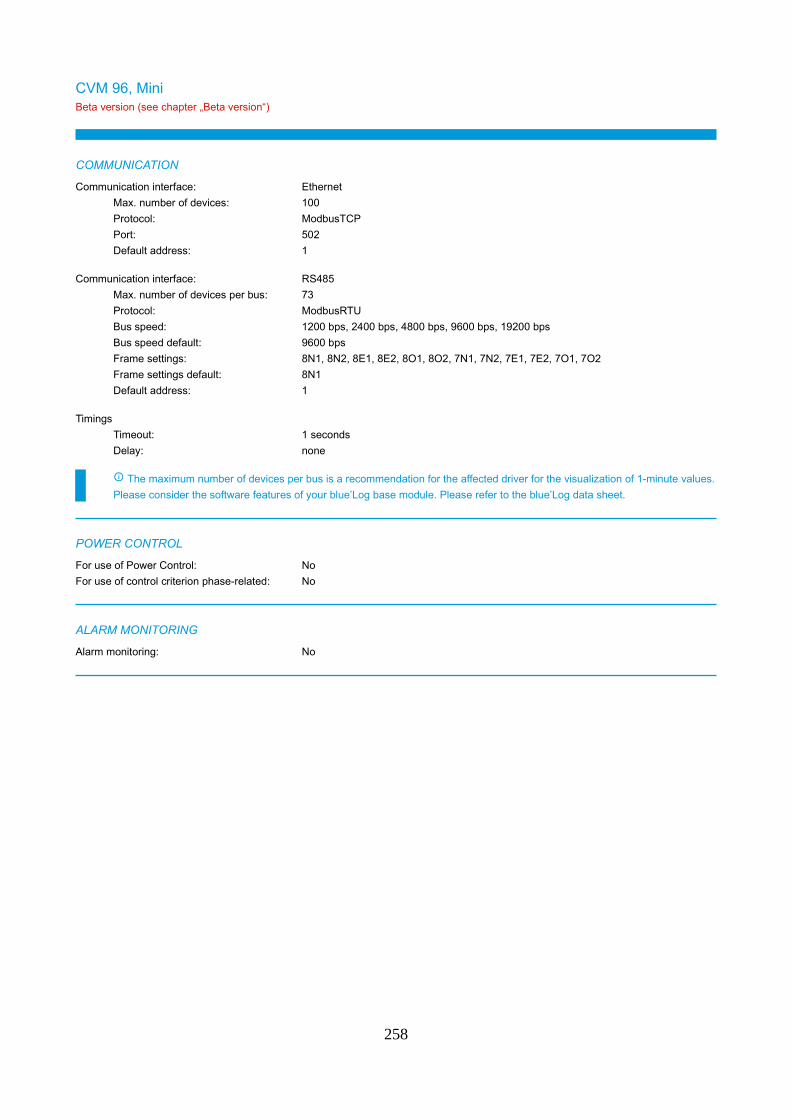
CVM 96, MiniBeta version (see chapter „Beta version“)
COMMUNICATION
Communication interface: Ethernet
Max. number of devices: 100
Protocol: ModbusTCP
Port: 502
Default address: 1
Communication interface: RS485
Max. number of devices per bus: 73
Protocol: ModbusRTU
Bus speed: 1200 bps, 2400 bps, 4800 bps, 9600 bps, 19200 bps
Bus speed default: 9600 bps
Frame settings: 8N1, 8N2, 8E1, 8E2, 8O1, 8O2, 7N1, 7N2, 7E1, 7E2, 7O1, 7O2
Frame settings default: 8N1
Default address: 1
Timings
Timeout: 1 seconds
Delay: none
The maximum number of devices per bus is a recommendation for the affected driver for the visualization of 1-minute values.
Please consider the software features of your blue’Log base module. Please refer to the blue’Log data sheet.
POWER CONTROL
For use of Power Control: No
For use of control criterion phase-related: No
ALARM MONITORING
Alarm monitoring: No
258
MEASUREMENT VALUES RECORDED
M_AC_E_EXP Active energy (export)
M_AC_E_IMP Active energy (import)
M_AC_F Grid frequency
M_AC_I1 Current AC phase 1
M_AC_I2 Current AC phase 2
M_AC_I3 Current AC phase 3
M_AC_P Power AC
M_AC_P1 Power AC phase 1
M_AC_P2 Power AC phase 2
M_AC_P3 Power AC phase 3
M_AC_PF_COSPHI Power factor (cos phi)
M_AC_PF_COSPHI1 Power factor (cos phi) phase 1
M_AC_PF_COSPHI2 Power factor (cos phi) phase 2
M_AC_PF_COSPHI3 Power factor (cos phi) phase 3
M_AC_Q Reactive power
M_AC_Q1 Reactive power, phase 1
M_AC_Q2 Reactive power, phase 2
M_AC_Q3 Reactive power, phase 3
M_AC_S Apparent power
M_AC_S1 Apparent power phase 1
M_AC_S2 Apparent power phase 2
M_AC_S3 Apparent power phase 3
M_AC_U1 Voltage AC phase 1
M_AC_U2 Voltage AC phase 2
M_AC_U3 Voltage AC phase 3
M_AC_U_L1L2 Phase voltage L1L2
M_AC_U_L2L3 Phase voltage L2L3
M_AC_U_L3L1 Phase voltage L3L1
T (1,...x) Temperature (1,...x)
The actually recorded values may vary due to the device model or the device firmware.
SUPPORTED DEVICES
CVM series
CVM_96 CVM_MINI
Please contact Sales for details of compatibility with devices not listed.
Phone: +49 (0)821 34666 - 80
E-mail: [email protected]
259
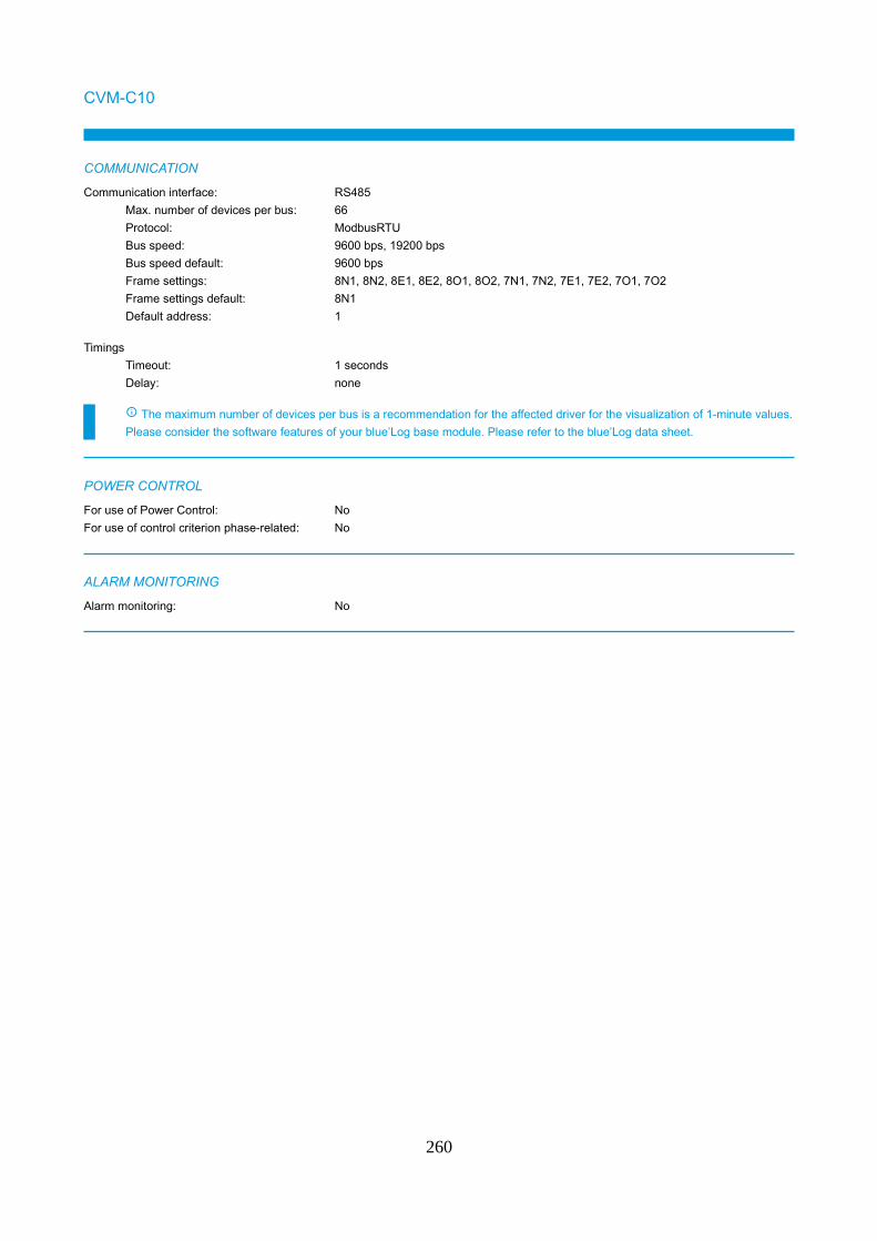
CVM-C10
COMMUNICATION
Communication interface: RS485
Max. number of devices per bus: 66
Protocol: ModbusRTU
Bus speed: 9600 bps, 19200 bps
Bus speed default: 9600 bps
Frame settings: 8N1, 8N2, 8E1, 8E2, 8O1, 8O2, 7N1, 7N2, 7E1, 7E2, 7O1, 7O2
Frame settings default: 8N1
Default address: 1
Timings
Timeout: 1 seconds
Delay: none
The maximum number of devices per bus is a recommendation for the affected driver for the visualization of 1-minute values.
Please consider the software features of your blue’Log base module. Please refer to the blue’Log data sheet.
POWER CONTROL
For use of Power Control: No
For use of control criterion phase-related: No
ALARM MONITORING
Alarm monitoring: No
260

MEASUREMENT VALUES RECORDED
M_AC_E_EXP Active energy (export)
M_AC_E_IMP Active energy (import)
M_AC_F Grid frequency
M_AC_I1 Current AC phase 1
M_AC_I2 Current AC phase 2
M_AC_I3 Current AC phase 3
M_AC_I_N Current, neutral conductor
M_AC_P Power AC
M_AC_P1 Power AC phase 1
M_AC_P2 Power AC phase 2
M_AC_P3 Power AC phase 3
M_AC_PF_COSPHI Power factor (cos phi)
M_AC_PF_COSPHI1 Power factor (cos phi) phase 1
M_AC_PF_COSPHI2 Power factor (cos phi) phase 2
M_AC_PF_COSPHI3 Power factor (cos phi) phase 3
M_AC_Q Reactive power
M_AC_Q1 Reactive power, phase 1
M_AC_Q2 Reactive power, phase 2
M_AC_Q3 Reactive power, phase 3
M_AC_S Apparent power
M_AC_S1 Apparent power phase 1
M_AC_S2 Apparent power phase 2
M_AC_S3 Apparent power phase 3
M_AC_U1 Voltage AC phase 1
M_AC_U2 Voltage AC phase 2
M_AC_U3 Voltage AC phase 3
M_AC_U_L1L2 Phase voltage L1L2
M_AC_U_L2L3 Phase voltage L2L3
M_AC_U_L3L1 Phase voltage L3L1
The actually recorded values may vary due to the device model or the device firmware.
261
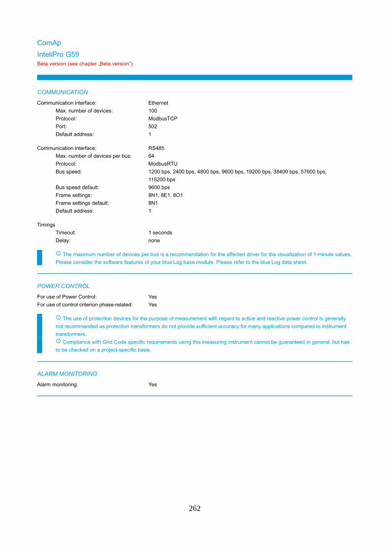
ComAp
InteliPro G59Beta version (see chapter „Beta version“)
COMMUNICATION
Communication interface: Ethernet
Max. number of devices: 100
Protocol: ModbusTCP
Port: 502
Default address: 1
Communication interface: RS485
Max. number of devices per bus: 64
Protocol: ModbusRTU
Bus speed: 1200 bps, 2400 bps, 4800 bps, 9600 bps, 19200 bps, 38400 bps, 57600 bps,
115200 bps
Bus speed default: 9600 bps
Frame settings: 8N1, 8E1, 8O1
Frame settings default: 8N1
Default address: 1
Timings
Timeout: 1 seconds
Delay: none
The maximum number of devices per bus is a recommendation for the affected driver for the visualization of 1-minute values.
Please consider the software features of your blue’Log base module. Please refer to the blue’Log data sheet.
POWER CONTROL
For use of Power Control: Yes
For use of control criterion phase-related: Yes
The use of protection devices for the purpose of measurement with regard to active and reactive power control is generally
not recommended as protection transformers do not provide sufficient accuracy for many applications compared to instrument
transformers.
Compliance with Grid Code specific requirements using this measuring instrument cannot be guaranteed in general, but has
to be checked on a project-specific basis.
ALARM MONITORING
Alarm monitoring: Yes
262

MEASUREMENT VALUES RECORDED
ERROR (1,...x) Error (1,...x)
M_AC_E_EXP Active energy (export)
M_AC_E_IMP Active energy (import)
M_AC_F Grid frequency
M_AC_I1 Current AC phase 1
M_AC_I2 Current AC phase 2
M_AC_I3 Current AC phase 3
M_AC_P Power AC
M_AC_P1 Power AC phase 1
M_AC_P2 Power AC phase 2
M_AC_P3 Power AC phase 3
M_AC_PF_COSPHI Power factor (cos phi)
M_AC_PF_COSPHI1 Power factor (cos phi) phase 1
M_AC_PF_COSPHI2 Power factor (cos phi) phase 2
M_AC_PF_COSPHI3 Power factor (cos phi) phase 3
M_AC_Q Reactive power
M_AC_Q1 Reactive power, phase 1
M_AC_Q2 Reactive power, phase 2
M_AC_Q3 Reactive power, phase 3
M_AC_S Apparent power
M_AC_S1 Apparent power phase 1
M_AC_S2 Apparent power phase 2
M_AC_S3 Apparent power phase 3
M_AC_U1 Voltage AC phase 1
M_AC_U2 Voltage AC phase 2
M_AC_U3 Voltage AC phase 3
M_AC_U_L1L2 Phase voltage L1L2
M_AC_U_L2L3 Phase voltage L2L3
M_AC_U_L3L1 Phase voltage L3L1
STATE (1,...x) Status (1,...x)
The actually recorded values may vary due to the device model or the device firmware.
263
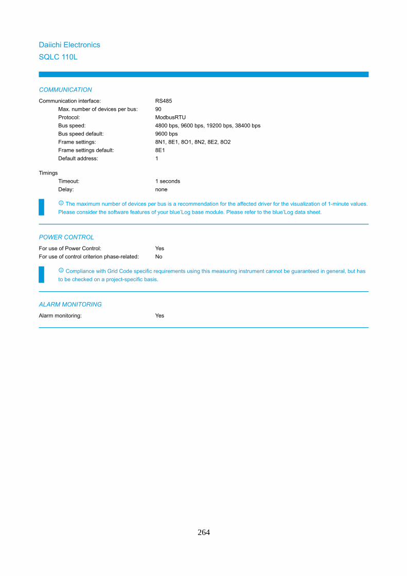
Daiichi Electronics
SQLC 110L
COMMUNICATION
Communication interface: RS485
Max. number of devices per bus: 90
Protocol: ModbusRTU
Bus speed: 4800 bps, 9600 bps, 19200 bps, 38400 bps
Bus speed default: 9600 bps
Frame settings: 8N1, 8E1, 8O1, 8N2, 8E2, 8O2
Frame settings default: 8E1
Default address: 1
Timings
Timeout: 1 seconds
Delay: none
The maximum number of devices per bus is a recommendation for the affected driver for the visualization of 1-minute values.
Please consider the software features of your blue’Log base module. Please refer to the blue’Log data sheet.
POWER CONTROL
For use of Power Control: Yes
For use of control criterion phase-related: No
Compliance with Grid Code specific requirements using this measuring instrument cannot be guaranteed in general, but has
to be checked on a project-specific basis.
ALARM MONITORING
Alarm monitoring: Yes
264
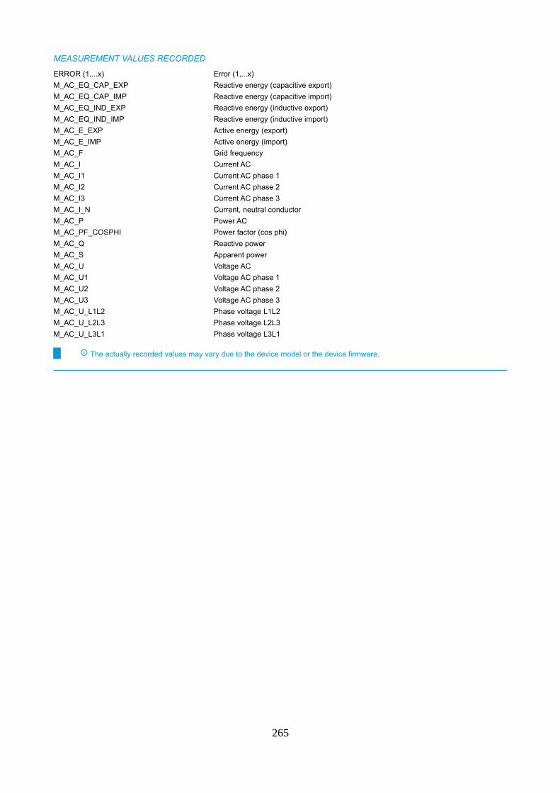
MEASUREMENT VALUES RECORDED
ERROR (1,...x) Error (1,...x)
M_AC_EQ_CAP_EXP Reactive energy (capacitive export)
M_AC_EQ_CAP_IMP Reactive energy (capacitive import)
M_AC_EQ_IND_EXP Reactive energy (inductive export)
M_AC_EQ_IND_IMP Reactive energy (inductive import)
M_AC_E_EXP Active energy (export)
M_AC_E_IMP Active energy (import)
M_AC_F Grid frequency
M_AC_I Current AC
M_AC_I1 Current AC phase 1
M_AC_I2 Current AC phase 2
M_AC_I3 Current AC phase 3
M_AC_I_N Current, neutral conductor
M_AC_P Power AC
M_AC_PF_COSPHI Power factor (cos phi)
M_AC_Q Reactive power
M_AC_S Apparent power
M_AC_U Voltage AC
M_AC_U1 Voltage AC phase 1
M_AC_U2 Voltage AC phase 2
M_AC_U3 Voltage AC phase 3
M_AC_U_L1L2 Phase voltage L1L2
M_AC_U_L2L3 Phase voltage L2L3
M_AC_U_L3L1 Phase voltage L3L1
The actually recorded values may vary due to the device model or the device firmware.
265
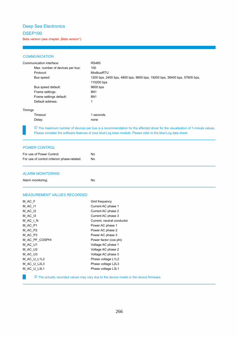
Deep Sea Electronics
DSEP100Beta version (see chapter „Beta version“)
COMMUNICATION
Communication interface: RS485
Max. number of devices per bus: 100
Protocol: ModbusRTU
Bus speed: 1200 bps, 2400 bps, 4800 bps, 9600 bps, 19200 bps, 38400 bps, 57600 bps,
115200 bps
Bus speed default: 9600 bps
Frame settings: 8N1
Frame settings default: 8N1
Default address: 1
Timings
Timeout: 1 seconds
Delay: none
The maximum number of devices per bus is a recommendation for the affected driver for the visualization of 1-minute values.
Please consider the software features of your blue’Log base module. Please refer to the blue’Log data sheet.
POWER CONTROL
For use of Power Control: No
For use of control criterion phase-related: No
ALARM MONITORING
Alarm monitoring: No
MEASUREMENT VALUES RECORDED
M_AC_F Grid frequency
M_AC_I1 Current AC phase 1
M_AC_I2 Current AC phase 2
M_AC_I3 Current AC phase 3
M_AC_I_N Current, neutral conductor
M_AC_P1 Power AC phase 1
M_AC_P2 Power AC phase 2
M_AC_P3 Power AC phase 3
M_AC_PF_COSPHI Power factor (cos phi)
M_AC_U1 Voltage AC phase 1
M_AC_U2 Voltage AC phase 2
M_AC_U3 Voltage AC phase 3
M_AC_U_L1L2 Phase voltage L1L2
M_AC_U_L2L3 Phase voltage L2L3
M_AC_U_L3L1 Phase voltage L3L1
The actually recorded values may vary due to the device model or the device firmware.
266
DEIF
ASC Main meterBeta version (see chapter „Beta version“)
COMMUNICATION
Communication interface: Ethernet
Max. number of devices: 100
Protocol: ModbusTCP
Port: 502
Default address: 1
Timings
Timeout: 1 seconds
Delay: 0.02 seconds
The maximum number of devices per bus is a recommendation for the affected driver for the visualization of 1-minute values.
Please consider the software features of your blue’Log base module. Please refer to the blue’Log data sheet.
Depending on the amount of main meters connected to the DEIF Controller the total amount of devices varies that can be
connected to one blue’Log (e.g. 1 x DEIF ASC = up to 16 devices).
POWER CONTROL
For use of Power Control: No
For use of control criterion phase-related: No
ALARM MONITORING
Alarm monitoring: No
MEASUREMENT VALUES RECORDED
D_IN (1,...x) Digital input (1,...x)
M_AC_P Power AC
M_AC_Q Reactive power
The actually recorded values may vary due to the device model or the device firmware.
267

Eaton
EDR-5000Beta version (see chapter „Beta version“)
COMMUNICATION
Communication interface: Ethernet
Max. number of devices: 100
Protocol: ModbusTCP
Port: 502
Default address: 1
Communication interface: RS485
Max. number of devices per bus: 100
Protocol: ModbusRTU
Bus speed: 1200 bps, 2400 bps, 4800 bps, 9600 bps, 19200 bps, 38400 bps
Bus speed default: 19200 bps
Frame settings: 8N1, 8N2, 8E1, 8O1
Frame settings default: 8E1
Default address: 1
Timings
Timeout: 1 seconds
Delay: none
The maximum number of devices per bus is a recommendation for the affected driver for the visualization of 1-minute values.
Please consider the software features of your blue’Log base module. Please refer to the blue’Log data sheet.
POWER CONTROL
For use of Power Control: Yes
For use of control criterion phase-related: No
The use of protection devices for the purpose of measurement with regard to active and reactive power control is generally
not recommended as protection transformers do not provide sufficient accuracy for many applications compared to instrument
transformers.
Compliance with Grid Code specific requirements using this measuring instrument cannot be guaranteed in general, but has
to be checked on a project-specific basis.
ALARM MONITORING
Alarm monitoring: No
268
MEASUREMENT VALUES RECORDED
M_AC_EQ_IND_EXP Reactive energy (inductive export)
M_AC_EQ_IND_IMP Reactive energy (inductive import)
M_AC_E_EXP Active energy (export)
M_AC_E_IMP Active energy (import)
M_AC_F Grid frequency
M_AC_I1 Current AC phase 1
M_AC_I2 Current AC phase 2
M_AC_I3 Current AC phase 3
M_AC_P Power AC
M_AC_PF_COSPHI Power factor (cos phi)
M_AC_Q Reactive power
M_AC_S Apparent power
M_AC_U1 Voltage AC phase 1
M_AC_U2 Voltage AC phase 2
M_AC_U3 Voltage AC phase 3
M_AC_U_L1L2 Phase voltage L1L2
M_AC_U_L2L3 Phase voltage L2L3
M_AC_U_L3L1 Phase voltage L3L1
The actually recorded values may vary due to the device model or the device firmware.
269
EDMI
SmartHub
COMMUNICATION
Communication interface: RS485
Max. number of devices per bus: 100
Protocol: ModbusRTU
Bus speed: 9600 bps
Bus speed default: 9600 bps
Frame settings: 8N1
Frame settings default: 8N1
Default address: 1
Timings
Timeout: 1 seconds
Delay: none
The maximum number of devices per bus is a recommendation for the affected driver for the visualization of 1-minute values.
Please consider the software features of your blue’Log base module. Please refer to the blue’Log data sheet.
Please note the last two digits of the serial number of the connected meter represent the Modbus address of the device. It is
not possible to connect two meters with identical Modbus addresses to the same RS485 bus.
POWER CONTROL
For use of Power Control: Yes
For use of control criterion phase-related: Yes
Compliance with Grid Code specific requirements using this measuring instrument cannot be guaranteed in general, but has
to be checked on a project-specific basis.
ALARM MONITORING
Alarm monitoring: No
270

MEASUREMENT VALUES RECORDED
M_AC_E_EXP Active energy (export)
M_AC_E_IMP Active energy (import)
M_AC_F Grid frequency
M_AC_I1 Current AC phase 1
M_AC_I2 Current AC phase 2
M_AC_I3 Current AC phase 3
M_AC_P Power AC
M_AC_P1 Power AC phase 1
M_AC_P2 Power AC phase 2
M_AC_P3 Power AC phase 3
M_AC_PF_COSPHI Power factor (cos phi)
M_AC_PF_COSPHI1 Power factor (cos phi) phase 1
M_AC_PF_COSPHI2 Power factor (cos phi) phase 2
M_AC_PF_COSPHI3 Power factor (cos phi) phase 3
M_AC_Q Reactive power
M_AC_Q1 Reactive power, phase 1
M_AC_Q2 Reactive power, phase 2
M_AC_Q3 Reactive power, phase 3
M_AC_S Apparent power
M_AC_S1 Apparent power phase 1
M_AC_S2 Apparent power phase 2
M_AC_S3 Apparent power phase 3
M_AC_U1 Voltage AC phase 1
M_AC_U2 Voltage AC phase 2
M_AC_U3 Voltage AC phase 3
M_AC_U_L1L2 Phase voltage L1L2
M_AC_U_L2L3 Phase voltage L2L3
M_AC_U_L3L1 Phase voltage L3L1
The actually recorded values may vary due to the device model or the device firmware.
SUPPORTED DEVICES
SmartHub series
MK10E MK10H
Please contact Sales for details of compatibility with devices not listed.
Phone: +49 (0)821 34666 - 80
E-mail: [email protected]
271
Electro Industries/GaugeTech
Shark 100SBeta version (see chapter „Beta version“)
COMMUNICATION
Communication interface: RS485
Max. number of devices per bus: 65
Protocol: ModbusRTU
Bus speed: 9600 bps, 19200 bps, 38400 bps, 57600 bps
Bus speed default: 9600 bps
Frame settings: 8N1
Frame settings default: 8N1
Default address: 1
Timings
Timeout: 1 seconds
Delay: 0.02 seconds
The maximum number of devices per bus is a recommendation for the affected driver for the visualization of 1-minute values.
Please consider the software features of your blue’Log base module. Please refer to the blue’Log data sheet.
POWER CONTROL
For use of Power Control: Yes
For use of control criterion phase-related: No
Compliance with Grid Code specific requirements using this measuring instrument cannot be guaranteed in general, but has
to be checked on a project-specific basis.
ALARM MONITORING
Alarm monitoring: Yes
MEASUREMENT VALUES RECORDED
M_AC_E_EXP Active energy (export)
M_AC_E_IMP Active energy (import)
M_AC_F Grid frequency
M_AC_I1 Current AC phase 1
M_AC_I2 Current AC phase 2
M_AC_I3 Current AC phase 3
M_AC_I_N Current, neutral conductor
M_AC_P Power AC
M_AC_PF_COSPHI Power factor (cos phi)
M_AC_Q Reactive power
M_AC_S Apparent power
M_AC_U1 Voltage AC phase 1
M_AC_U2 Voltage AC phase 2
M_AC_U3 Voltage AC phase 3
M_AC_U_L1L2 Phase voltage L1L2
M_AC_U_L2L3 Phase voltage L2L3
M_AC_U_L3L1 Phase voltage L3L1
STATE (1,...x) Status (1,...x)
272

The actually recorded values may vary due to the device model or the device firmware.
273
Elster
A1700 / A1140 (KoCos ME27.1)Beta version (see chapter „Beta version“)
COMMUNICATION
Communication interface: RS485
Max. number of devices per bus: 100
Protocol: ModbusRTU
Bus speed: 300 bps, 600 bps, 1200 bps, 2400 bps, 4800 bps, 9600 bps, 19200 bps,
38400 bps, 57600 bps, 115200 bps
Bus speed default: 9600 bps
Frame settings: 7N1, 7E1, 7O1, 7N2, 7E2, 7O2, 8N1, 8E1, 8O1, 8N2, 8E2, 8O2
Frame settings default: 8N1
Default address: 1
Timings
Timeout: 1 seconds
Delay: none
The maximum number of devices per bus is a recommendation for the affected driver for the visualization of 1-minute values.
Please consider the software features of your blue’Log base module. Please refer to the blue’Log data sheet.
POWER CONTROL
For use of Power Control: No
For use of control criterion phase-related: No
ALARM MONITORING
Alarm monitoring: No
274
MEASUREMENT VALUES RECORDED
M_AC_E_EXP Active energy (export)
M_AC_E_IMP Active energy (import)
M_AC_F Grid frequency
M_AC_I1 Current AC phase 1
M_AC_I2 Current AC phase 2
M_AC_I3 Current AC phase 3
M_AC_P Power AC
M_AC_P1 Power AC phase 1
M_AC_P2 Power AC phase 2
M_AC_P3 Power AC phase 3
M_AC_PF_COSPHI Power factor (cos phi)
M_AC_PF_COSPHI1 Power factor (cos phi) phase 1
M_AC_PF_COSPHI2 Power factor (cos phi) phase 2
M_AC_PF_COSPHI3 Power factor (cos phi) phase 3
M_AC_Q Reactive power
M_AC_Q1 Reactive power, phase 1
M_AC_Q2 Reactive power, phase 2
M_AC_Q3 Reactive power, phase 3
M_AC_S Apparent power
M_AC_S1 Apparent power phase 1
M_AC_S2 Apparent power phase 2
M_AC_S3 Apparent power phase 3
M_AC_U1 Voltage AC phase 1
M_AC_U2 Voltage AC phase 2
M_AC_U3 Voltage AC phase 3
The actually recorded values may vary due to the device model or the device firmware.
275
Frer
C96...L
COMMUNICATION
Communication interface: Ethernet
Max. number of devices: 100
Protocol: ModbusTCP
Port: 502
Default address: 1
Communication interface: RS485
Max. number of devices per bus: 100
Protocol: ModbusRTU
Bus speed: 9600 bps, 19200 bps, 38400 bps
Bus speed default: 9600 bps
Frame settings: 8N1, 8N2, 8E1, 8E2, 8O1, 8O2
Frame settings default: 8N2
Default address: 1
Timings
Timeout: 1 seconds
Delay: 0.015 seconds
The maximum number of devices per bus is a recommendation for the affected driver for the visualization of 1-minute values.
Please consider the software features of your blue’Log base module. Please refer to the blue’Log data sheet.
POWER CONTROL
For use of Power Control: No
For use of control criterion phase-related: No
ALARM MONITORING
Alarm monitoring: No
MEASUREMENT VALUES RECORDED
M_AC_E_EXP Active energy (export)
M_AC_E_IMP Active energy (import)
M_AC_P Power AC
M_AC_PF_COSPHI Power factor (cos phi)
M_AC_PF_COSPHI1 Power factor (cos phi) phase 1
M_AC_PF_COSPHI2 Power factor (cos phi) phase 2
M_AC_PF_COSPHI3 Power factor (cos phi) phase 3
M_AC_Q Reactive power
The actually recorded values may vary due to the device model or the device firmware.
276
Hager
300C
COMMUNICATION
Communication interface: RS485
Max. number of devices per bus: 100
Protocol: ModbusRTU
Bus speed: 1200 bps, 2400 bps, 4800 bps, 9600 bps, 19200 bps, 38400 bps
Bus speed default: 19200 bps
Frame settings: 8E1, 8N1, 8O1, 8E2, 8N2, 8O2
Frame settings default: 8E1
Default address: 1
Timings
Timeout: 1 seconds
Delay: none
The maximum number of devices per bus is a recommendation for the affected driver for the visualization of 1-minute values.
Please consider the software features of your blue’Log base module. Please refer to the blue’Log data sheet.
POWER CONTROL
For use of Power Control: No
For use of control criterion phase-related: No
ALARM MONITORING
Alarm monitoring: No
277
MEASUREMENT VALUES RECORDED
M_AC_E_EXP Active energy (export)
M_AC_E_IMP Active energy (import)
M_AC_F Grid frequency
M_AC_I1 Current AC phase 1
M_AC_I2 Current AC phase 2
M_AC_I3 Current AC phase 3
M_AC_I_N Current, neutral conductor
M_AC_P Power AC
M_AC_P1 Power AC phase 1
M_AC_P2 Power AC phase 2
M_AC_P3 Power AC phase 3
M_AC_PF_COSPHI Power factor (cos phi)
M_AC_Q Reactive power
M_AC_Q1 Reactive power, phase 1
M_AC_Q2 Reactive power, phase 2
M_AC_Q3 Reactive power, phase 3
M_AC_S Apparent power
M_AC_S1 Apparent power phase 1
M_AC_S2 Apparent power phase 2
M_AC_S3 Apparent power phase 3
M_AC_U1 Voltage AC phase 1
M_AC_U2 Voltage AC phase 2
M_AC_U3 Voltage AC phase 3
M_AC_U_L1L2 Phase voltage L1L2
M_AC_U_L2L3 Phase voltage L2L3
M_AC_U_L3L1 Phase voltage L3L1
The actually recorded values may vary due to the device model or the device firmware.
SUPPORTED DEVICES
ECR300C ECR301C
Please contact Sales for details of compatibility with devices not listed.
Phone: +49 (0)821 34666 - 80
E-mail: [email protected]
278
Janitza
UMG series
COMMUNICATION
Communication interface: Ethernet
Max. number of devices: 100
Protocol: ModbusTCP
Port: 502
Default address: 1
Communication interface: RS485
Max. number of devices per bus: 100
Protocol: ModbusRTU
Bus speed: 9600 bps, 19200 bps, 38400 bps, 57600 bps, 115200 bps
Bus speed default: 115200 bps
Frame settings: 8N1, 8N2
Frame settings default: 8N1
Default address: 1
Timings
Timeout: 1 seconds
Delay: none
The maximum number of devices per bus is a recommendation for the affected driver for the visualization of 1-minute values.
Please consider the software features of your blue’Log base module. Please refer to the blue’Log data sheet.
POWER CONTROL
For use of Power Control: Yes
For use of control criterion phase-related: Yes
Compliance with Grid Code specific requirements using this measuring instrument cannot be guaranteed in general, but has
to be checked on a project-specific basis.
ALARM MONITORING
Alarm monitoring: No
279
MEASUREMENT VALUES RECORDED
M_AC_E_EXP Active energy (export)
M_AC_E_IMP Active energy (import)
M_AC_F Grid frequency
M_AC_I1 Current AC phase 1
M_AC_I2 Current AC phase 2
M_AC_I3 Current AC phase 3
M_AC_P Power AC
M_AC_P1 Power AC phase 1
M_AC_P2 Power AC phase 2
M_AC_P3 Power AC phase 3
M_AC_PF_COSPHI Power factor (cos phi)
M_AC_PF_COSPHI1 Power factor (cos phi) phase 1
M_AC_PF_COSPHI2 Power factor (cos phi) phase 2
M_AC_PF_COSPHI3 Power factor (cos phi) phase 3
M_AC_Q Reactive power
M_AC_Q1 Reactive power, phase 1
M_AC_Q2 Reactive power, phase 2
M_AC_Q3 Reactive power, phase 3
M_AC_S Apparent power
M_AC_S1 Apparent power phase 1
M_AC_S2 Apparent power phase 2
M_AC_S3 Apparent power phase 3
M_AC_U1 Voltage AC phase 1
M_AC_U2 Voltage AC phase 2
M_AC_U3 Voltage AC phase 3
M_AC_U_L1L2 Phase voltage L1L2
M_AC_U_L2L3 Phase voltage L2L3
M_AC_U_L3L1 Phase voltage L3L1
The actually recorded values may vary due to the device model or the device firmware.
SUPPORTED DEVICES
UMG series
UMG 96PA UMG 96RM UMG 96RM-E
UMG 96RM-EL UMG 103 CBM UMG 104
UMG 508 UMG 509 UMG 511
UMG 512 UMG 604 UMG 605
Please contact Sales for details of compatibility with devices not listed.
Phone: +49 (0)821 34666 - 80
E-mail: [email protected]
280
Landis & Gyr
E650 (Marcom Gateway)Beta version (see chapter „Beta version“)
COMMUNICATION
Communication interface: Ethernet
Max. number of devices: 100
Protocol: ModbusTCP
Port: 502
Default address: 1
Communication interface: RS485
Max. number of devices per bus: 100
Protocol: ModbusRTU
Bus speed: 9600 bps
Bus speed default: 9600 bps
Frame settings: 8N1
Frame settings default: 8N1
Default address: 1
Timings
Timeout: 1 seconds
Delay: none
The maximum number of devices per bus is a recommendation for the affected driver for the visualization of 1-minute values.
Please consider the software features of your blue’Log base module. Please refer to the blue’Log data sheet.
You can connect up to 4 Landis & Gyr E650 meters to one Marcom gateway (e.g. 1 Marcom with 4 Landis & Gyr E650 = 4
devices).
POWER CONTROL
For use of Power Control: No
For use of control criterion phase-related: No
ALARM MONITORING
Alarm monitoring: No
MEASUREMENT VALUES RECORDED
M_AC_E_EXP Active energy (export)
M_AC_E_IMP Active energy (import)
M_AC_PF_COSPHI Power factor (cos phi)
M_AC_U1 Voltage AC phase 1
M_AC_U2 Voltage AC phase 2
M_AC_U3 Voltage AC phase 3
The actually recorded values may vary due to the device model or the device firmware.
281
Lovato
PMVF seriesBeta version (see chapter „Beta version“)
COMMUNICATION
Communication interface: Ethernet
Max. number of devices: 100
Protocol: ModbusTCP
Port: 1001
Default address: 1
Communication interface: RS485
Max. number of devices per bus: 87
Protocol: ModbusRTU
Bus speed: 1200 bps, 2400 bps, 4800 bps, 9600 bps, 19200 bps, 38400 bps, 57600 bps,
115200 bps
Bus speed default: 9600 bps
Frame settings: 7O1, 7O2, 7E1, 7E2, 8N1, 8N2, 8O1, 8O2, 8E1, 8E2
Frame settings default: 8N1
Default address: 1
Timings
Timeout: 1 seconds
Delay: none
The maximum number of devices per bus is a recommendation for the affected driver for the visualization of 1-minute values.
Please consider the software features of your blue’Log base module. Please refer to the blue’Log data sheet.
POWER CONTROL
For use of Power Control: No
For use of control criterion phase-related: No
ALARM MONITORING
Alarm monitoring: Yes
282
MEASUREMENT VALUES RECORDED
ERROR (1,...x) Error (1,...x)
M_AC_E_EXP Active energy (export)
M_AC_E_IMP Active energy (import)
M_AC_F Grid frequency
M_AC_I1 Current AC phase 1
M_AC_I2 Current AC phase 2
M_AC_I3 Current AC phase 3
M_AC_P1 Power AC phase 1
M_AC_P2 Power AC phase 2
M_AC_P3 Power AC phase 3
M_AC_PF_COSPHI Power factor (cos phi)
M_AC_PF_COSPHI1 Power factor (cos phi) phase 1
M_AC_PF_COSPHI2 Power factor (cos phi) phase 2
M_AC_PF_COSPHI3 Power factor (cos phi) phase 3
M_AC_Q1 Reactive power, phase 1
M_AC_Q2 Reactive power, phase 2
M_AC_Q3 Reactive power, phase 3
M_AC_S1 Apparent power phase 1
M_AC_S2 Apparent power phase 2
M_AC_S3 Apparent power phase 3
M_AC_U1 Voltage AC phase 1
M_AC_U2 Voltage AC phase 2
M_AC_U3 Voltage AC phase 3
M_AC_U_L1L2 Phase voltage L1L2
M_AC_U_L2L3 Phase voltage L2L3
M_AC_U_L3L1 Phase voltage L3L1
STATE (1,...x) Status (1,...x)
The actually recorded values may vary due to the device model or the device firmware.
SUPPORTED DEVICES
PMVF series
PMVF20 PMVF50 PMVF51
Please contact Sales for details of compatibility with devices not listed.
Phone: +49 (0)821 34666 - 80
E-mail: [email protected]
283
Meter Gateway
L-Box
COMMUNICATION
Communication interface: Ethernet
Max. number of devices: 100
Protocol: http
Port: 8080
Default address: 0
Timings
Timeout: none
Delay: 60 seconds
The maximum number of devices per bus is a recommendation for the affected driver for the visualization of 1-minute values.
Please consider the software features of your blue’Log base module. Please refer to the blue’Log data sheet.
POWER CONTROL
For use of Power Control: No
For use of control criterion phase-related: No
ALARM MONITORING
Alarm monitoring: No
MEASUREMENT VALUES RECORDED
M_AC_E_EXP Active energy (export)
M_AC_E_IMP Active energy (import)
M_AC_PF_COSPHI Power factor (cos phi)
M_EV_E_EXP Consumption of charging infrastructure
The actually recorded values may vary due to the device model or the device firmware.
284
Metering Dynamics
SmartHub
COMMUNICATION
Communication interface: RS485
Max. number of devices per bus: 5
Protocol: ModbusRTU
Bus speed: 9600 bps
Bus speed default: 9600 bps
Frame settings: 8N1
Frame settings default: 8N1
Default address: 1
Timings
Timeout: 6 seconds
Delay: 6 seconds
The maximum number of devices per bus is a recommendation for the affected driver for the visualization of 1-minute values.
Please consider the software features of your blue’Log base module. Please refer to the blue’Log data sheet.
Please note the last two digits of the serial number of the connected meter represent the Modbus address of the device. It is
not possible to connect two meters with identical Modbus addresses to the same RS485 bus.
POWER CONTROL
For use of Power Control: No
For use of control criterion phase-related: No
ALARM MONITORING
Alarm monitoring: No
MEASUREMENT VALUES RECORDED
M_AC_E_EXP Active energy (export)
M_AC_E_IMP Active energy (import)
M_AC_F Grid frequency
M_AC_I1 Current AC phase 1
M_AC_I2 Current AC phase 2
M_AC_I3 Current AC phase 3
M_AC_P1 Power AC phase 1
M_AC_P2 Power AC phase 2
M_AC_P3 Power AC phase 3
M_AC_PF_COSPHI Power factor (cos phi)
M_AC_Q1 Reactive power, phase 1
M_AC_Q2 Reactive power, phase 2
M_AC_Q3 Reactive power, phase 3
M_AC_S1 Apparent power phase 1
M_AC_S2 Apparent power phase 2
M_AC_S3 Apparent power phase 3
M_AC_U1 Voltage AC phase 1
M_AC_U2 Voltage AC phase 2
M_AC_U3 Voltage AC phase 3
285

The actually recorded values may vary due to the device model or the device firmware.
SUPPORTED DEVICES
SmartHub series
MK10A MK10E
Please contact Sales for details of compatibility with devices not listed.
Phone: +49 (0)821 34666 - 80
E-mail: [email protected]
286
Microstar
P2000
COMMUNICATION
Communication interface: RS485
Max. number of devices per bus: 19
Protocol: ModbusRTU
Bus speed: 9600 bps
Bus speed default: 9600 bps
Frame settings: 8N1
Frame settings default: 8N1
Default address: 1
Timings
Timeout: 2 seconds
Delay: 0.1 seconds
The maximum number of devices per bus is a recommendation for the affected driver for the visualization of 1-minute values.
Please consider the software features of your blue’Log base module. Please refer to the blue’Log data sheet.
POWER CONTROL
For use of Power Control: No
For use of control criterion phase-related: No
ALARM MONITORING
Alarm monitoring: No
287
MEASUREMENT VALUES RECORDED
M_AC_ES_EXP Apparent energy (exported)
M_AC_ES_IMP Apparent energy (imported)
M_AC_E_EXP Active energy (export)
M_AC_E_IMP Active energy (import)
M_AC_F Grid frequency
M_AC_I1 Current AC phase 1
M_AC_I2 Current AC phase 2
M_AC_I3 Current AC phase 3
M_AC_P Power AC
M_AC_P1 Power AC phase 1
M_AC_P2 Power AC phase 2
M_AC_P3 Power AC phase 3
M_AC_PF_COSPHI Power factor (cos phi)
M_AC_PF_COSPHI1 Power factor (cos phi) phase 1
M_AC_PF_COSPHI2 Power factor (cos phi) phase 2
M_AC_PF_COSPHI3 Power factor (cos phi) phase 3
M_AC_Q Reactive power
M_AC_Q1 Reactive power, phase 1
M_AC_Q2 Reactive power, phase 2
M_AC_Q3 Reactive power, phase 3
M_AC_S Apparent power
M_AC_U1 Voltage AC phase 1
M_AC_U2 Voltage AC phase 2
M_AC_U3 Voltage AC phase 3
The actually recorded values may vary due to the device model or the device firmware.
288
Mitsubishi
ME110
COMMUNICATION
Communication interface: RS485
Max. number of devices per bus: 9
Protocol: ModbusRTU
Bus speed: 2400 bps, 4800 bps, 9600 bps, 19200 bps, 38400 bps
Bus speed default: 19200 bps
Frame settings: 8E1, 8O1, 8N1, 8E2, 8O2, 8N2
Frame settings default: 8E1
Default address: 1
Timings
Timeout: 1.5 seconds
Delay: 1 seconds
The maximum number of devices per bus is a recommendation for the affected driver for the visualization of 1-minute values.
Please consider the software features of your blue’Log base module. Please refer to the blue’Log data sheet.
POWER CONTROL
For use of Power Control: Yes
For use of control criterion phase-related: Yes
Compliance with Grid Code specific requirements using this measuring instrument cannot be guaranteed in general, but has
to be checked on a project-specific basis.
ALARM MONITORING
Alarm monitoring: Yes
289
MEASUREMENT VALUES RECORDED
ERROR (1,...x) Error (1,...x)
M_AC_E_EXP Active energy (export)
M_AC_E_IMP Active energy (import)
M_AC_F Grid frequency
M_AC_I1 Current AC phase 1
M_AC_I2 Current AC phase 2
M_AC_I3 Current AC phase 3
M_AC_P Power AC
M_AC_P1 Power AC phase 1
M_AC_P2 Power AC phase 2
M_AC_P3 Power AC phase 3
M_AC_PF_COSPHI Power factor (cos phi)
M_AC_PF_COSPHI1 Power factor (cos phi) phase 1
M_AC_PF_COSPHI2 Power factor (cos phi) phase 2
M_AC_PF_COSPHI3 Power factor (cos phi) phase 3
M_AC_Q Reactive power
M_AC_Q1 Reactive power, phase 1
M_AC_Q2 Reactive power, phase 2
M_AC_Q3 Reactive power, phase 3
M_AC_S Apparent power
M_AC_S1 Apparent power phase 1
M_AC_S2 Apparent power phase 2
M_AC_S3 Apparent power phase 3
M_AC_U1 Voltage AC phase 1
M_AC_U2 Voltage AC phase 2
M_AC_U3 Voltage AC phase 3
M_AC_U_L1L2 Phase voltage L1L2
M_AC_U_L2L3 Phase voltage L2L3
M_AC_U_L3L1 Phase voltage L3L1
The actually recorded values may vary due to the device model or the device firmware.
SUPPORTED DEVICES
ME110 series
ME110NSR-MB ME110SR-MB ME110SSR-MB
Please contact Sales for details of compatibility with devices not listed.
Phone: +49 (0)821 34666 - 80
E-mail: [email protected]
290
PQ Plus
UMD series
COMMUNICATION
Communication interface: Ethernet
Max. number of devices: 100
Protocol: ModbusTCP
Port: 502
Default address: 1
Communication interface: RS485
Max. number of devices per bus: 100
Protocol: ModbusRTU
Bus speed: 2400 bps, 4800 bps, 9600 bps, 19200 bps, 38400 bps, 57600 bps, 115200 bps
Bus speed default: 9600 bps
Frame settings: 8N1, 8N2, 8E1, 8E2, 8O1, 8O2, 7N1, 7N2, 7E1, 7E2, 7O1, 7O2
Frame settings default: 8N1
Default address: 1
Timings
Timeout: 1 seconds
Delay: none
The maximum number of devices per bus is a recommendation for the affected driver for the visualization of 1-minute values.
Please consider the software features of your blue’Log base module. Please refer to the blue’Log data sheet.
Only devices from firmware 3.0.8 and higher get supported.
POWER CONTROL
For use of Power Control: Yes
For use of control criterion phase-related: Yes
Compliance with Grid Code specific requirements using this measuring instrument cannot be guaranteed in general, but has
to be checked on a project-specific basis.
ALARM MONITORING
Alarm monitoring: No
291
MEASUREMENT VALUES RECORDED
M_AC_E_EXP Active energy (export)
M_AC_E_IMP Active energy (import)
M_AC_F Grid frequency
M_AC_I1 Current AC phase 1
M_AC_I2 Current AC phase 2
M_AC_I3 Current AC phase 3
M_AC_P Power AC
M_AC_P1 Power AC phase 1
M_AC_P2 Power AC phase 2
M_AC_P3 Power AC phase 3
M_AC_PF_COSPHI Power factor (cos phi)
M_AC_PF_COSPHI1 Power factor (cos phi) phase 1
M_AC_PF_COSPHI2 Power factor (cos phi) phase 2
M_AC_PF_COSPHI3 Power factor (cos phi) phase 3
M_AC_Q Reactive power
M_AC_Q1 Reactive power, phase 1
M_AC_Q2 Reactive power, phase 2
M_AC_Q3 Reactive power, phase 3
M_AC_S Apparent power
M_AC_S1 Apparent power phase 1
M_AC_S2 Apparent power phase 2
M_AC_S3 Apparent power phase 3
M_AC_U1 Voltage AC phase 1
M_AC_U2 Voltage AC phase 2
M_AC_U3 Voltage AC phase 3
M_AC_U_L1L2 Phase voltage L1L2
M_AC_U_L2L3 Phase voltage L2L3
M_AC_U_L3L1 Phase voltage L3L1
The actually recorded values may vary due to the device model or the device firmware.
If you use the meter in single phase mode it's necessary to configure this in meter software. Otherwise the meter will show
also values for phase 2 and phase 3. Set in the menu "Install" - "Advanced" the option "Markierung bei Phasenausfall" to the
value "Flag+0".
SUPPORTED DEVICES
UMD 96 UMD 97 UMD 97EVU
UMD 98 UMD 701 UMD 704
UMD 705E/CBM UMD 705X UMD 707
UMD 709 UMD 710A UMD 710EVU
UMD 807 UMD 913
Please contact Sales for details of compatibility with devices not listed.
Phone: +49 (0)821 34666 - 80
E-mail: [email protected]
292
Regulus
uRegBeta version (see chapter „Beta version“)
COMMUNICATION
Communication interface: Ethernet
Max. number of devices: 100
Protocol: ModbusTCP
Port: 502
Default address: 1
Communication interface: RS485
Max. number of devices per bus: 100
Protocol: ModbusRTU
Bus speed: 115200 bps
Bus speed default: 115200 bps
Frame settings: 8N1
Frame settings default: 8N1
Default address: 1
Timings
Timeout: 1 seconds
Delay: none
The maximum number of devices per bus is a recommendation for the affected driver for the visualization of 1-minute values.
Please consider the software features of your blue’Log base module. Please refer to the blue’Log data sheet.
POWER CONTROL
For use of Power Control: No
For use of control criterion phase-related: No
ALARM MONITORING
Alarm monitoring: No
MEASUREMENT VALUES RECORDED
M_AC_E_EXP Active energy (export)
M_AC_E_IMP Active energy (import)
M_AC_F Grid frequency
M_AC_I1 Current AC phase 1
M_AC_I2 Current AC phase 2
M_AC_I3 Current AC phase 3
M_AC_P Power AC
M_AC_PF_COSPHI Power factor (cos phi)
M_AC_Q Reactive power
M_AC_U1 Voltage AC phase 1
M_AC_U2 Voltage AC phase 2
M_AC_U3 Voltage AC phase 3
M_AC_U_L1L2 Phase voltage L1L2
M_AC_U_L2L3 Phase voltage L2L3
M_AC_U_L3L1 Phase voltage L3L1
293

The actually recorded values may vary due to the device model or the device firmware.
294
Satec
PM13xP/A/E/EHBeta version (see chapter „Beta version“)
COMMUNICATION
Communication interface: Ethernet
Max. number of devices: 100
Protocol: ModbusTCP
Port: 502
Default address: 1
Communication interface: RS485
Max. number of devices per bus: 61
Protocol: ModbusRTU
Bus speed: 300 bps, 600 bps, 1200 bps, 2400 bps, 4800 bps, 9600 bps, 19200 bps,
38400 bps, 57600 bps, 115200 bps
Bus speed default: 9600 bps
Frame settings: 7E1, 8N1, 8E1
Frame settings default: 8N1
Default address: 1
Timings
Timeout: 1 seconds
Delay: 0.005 seconds
The maximum number of devices per bus is a recommendation for the affected driver for the visualization of 1-minute values.
Please consider the software features of your blue’Log base module. Please refer to the blue’Log data sheet.
Please note that it is possible to change the data format by changing the configuration of the meter. Because 32-bit floating
point format is not supported by this driver, register 246 needs to be 0 (default value) and shouldn't be changed.
POWER CONTROL
For use of Power Control: Yes
For use of control criterion phase-related: Yes
Compliance with Grid Code specific requirements using this measuring instrument cannot be guaranteed in general, but has
to be checked on a project-specific basis.
ALARM MONITORING
Alarm monitoring: No
295
MEASUREMENT VALUES RECORDED
D_IN (1,...x) Digital input (1,...x)
M_AC_E_EXP Active energy (export)
M_AC_E_IMP Active energy (import)
M_AC_F Grid frequency
M_AC_I1 Current AC phase 1
M_AC_I2 Current AC phase 2
M_AC_I3 Current AC phase 3
M_AC_I_N Current, neutral conductor
M_AC_P Power AC
M_AC_P1 Power AC phase 1
M_AC_P2 Power AC phase 2
M_AC_P3 Power AC phase 3
M_AC_PF_COSPHI Power factor (cos phi)
M_AC_PF_COSPHI1 Power factor (cos phi) phase 1
M_AC_PF_COSPHI2 Power factor (cos phi) phase 2
M_AC_PF_COSPHI3 Power factor (cos phi) phase 3
M_AC_Q Reactive power
M_AC_Q1 Reactive power, phase 1
M_AC_Q2 Reactive power, phase 2
M_AC_Q3 Reactive power, phase 3
M_AC_S Apparent power
M_AC_S1 Apparent power phase 1
M_AC_S2 Apparent power phase 2
M_AC_S3 Apparent power phase 3
M_AC_U1 Voltage AC phase 1
M_AC_U2 Voltage AC phase 2
M_AC_U3 Voltage AC phase 3
M_AC_U_L1L2 Phase voltage L1L2
M_AC_U_L2L3 Phase voltage L2L3
M_AC_U_L3L1 Phase voltage L3L1
The actually recorded values may vary due to the device model or the device firmware.
SUPPORTED DEVICES
PM130 PLUS series
PM130A PM130E PM130EH
PM130P
PM135 series
PM135A PM135E PM135EH
PM135P
Please contact Sales for details of compatibility with devices not listed.
Phone: +49 (0)821 34666 - 80
E-mail: [email protected]
296
SBC
ALE3 / AWD3Beta version (see chapter „Beta version“)
COMMUNICATION
Communication interface: RS485
Max. number of devices per bus: 14
Protocol: ModbusRTU
Bus speed: 1200 bps, 2400 bps, 4800 bps, 9600 bps, 19200 bps, 38400 bps, 57600 bps,
115200 bps
Bus speed default: 9600 bps
Frame settings: 8N1, 8E1, 8O1
Frame settings default: 8E1
Default address: 1
Timings
Timeout: 5 seconds
Delay: 1 seconds
The maximum number of devices per bus is a recommendation for the affected driver for the visualization of 1-minute values.
Please consider the software features of your blue’Log base module. Please refer to the blue’Log data sheet.
POWER CONTROL
For use of Power Control: No
For use of control criterion phase-related: No
ALARM MONITORING
Alarm monitoring: Yes
MEASUREMENT VALUES RECORDED
ERROR (1,...x) Error (1,...x)
M_AC_E_EXP Active energy (export)
M_AC_I1 Current AC phase 1
M_AC_I2 Current AC phase 2
M_AC_I3 Current AC phase 3
M_AC_P Power AC
M_AC_P1 Power AC phase 1
M_AC_P2 Power AC phase 2
M_AC_P3 Power AC phase 3
M_AC_PF_COSPHI1 Power factor (cos phi) phase 1
M_AC_PF_COSPHI2 Power factor (cos phi) phase 2
M_AC_PF_COSPHI3 Power factor (cos phi) phase 3
M_AC_Q Reactive power
M_AC_Q1 Reactive power, phase 1
M_AC_Q2 Reactive power, phase 2
M_AC_Q3 Reactive power, phase 3
M_AC_U1 Voltage AC phase 1
M_AC_U2 Voltage AC phase 2
M_AC_U3 Voltage AC phase 3
297

The actually recorded values may vary due to the device model or the device firmware.
SUPPORTED DEVICES
ALE3 AWD3
Please contact Sales for details of compatibility with devices not listed.
Phone: +49 (0)821 34666 - 80
E-mail: [email protected]
298
Schneider Electric
EM125X
COMMUNICATION
Communication interface: RS485
Max. number of devices per bus: 100
Protocol: ModbusRTU
Bus speed: 4800 bps, 9600 bps, 19200 bps
Bus speed default: 19200 bps
Frame settings: 8N2, 8O1, 8E1
Frame settings default: 8E1
Default address: 1
Timings
Timeout: 1 seconds
Delay: none
The maximum number of devices per bus is a recommendation for the affected driver for the visualization of 1-minute values.
Please consider the software features of your blue’Log base module. Please refer to the blue’Log data sheet.
POWER CONTROL
For use of Power Control: No
For use of control criterion phase-related: No
ALARM MONITORING
Alarm monitoring: Yes
MEASUREMENT VALUES RECORDED
ERROR (1,...x) Error (1,...x)
M_AC_ES_EXP Apparent energy (exported)
M_AC_E_EXP Active energy (export)
M_AC_P Power AC
M_AC_P1 Power AC phase 1
M_AC_P2 Power AC phase 2
M_AC_P3 Power AC phase 3
M_AC_PF_COSPHI Power factor (cos phi)
M_AC_PF_COSPHI1 Power factor (cos phi) phase 1
M_AC_PF_COSPHI2 Power factor (cos phi) phase 2
M_AC_PF_COSPHI3 Power factor (cos phi) phase 3
M_AC_Q Reactive power
M_AC_Q1 Reactive power, phase 1
M_AC_Q2 Reactive power, phase 2
M_AC_Q3 Reactive power, phase 3
M_AC_S Apparent power
M_AC_S1 Apparent power phase 1
M_AC_S2 Apparent power phase 2
M_AC_S3 Apparent power phase 3
STATE (1,...x) Status (1,...x)
The actually recorded values may vary due to the device model or the device firmware.
299

SUPPORTED DEVICES
EM1250 EM1251
Please contact Sales for details of compatibility with devices not listed.
Phone: +49 (0)821 34666 - 80
E-mail: [email protected]
300
iEM3155 / iEM3255 / iEM3355
COMMUNICATION
Communication interface: RS485
Max. number of devices per bus: 100
Protocol: ModbusRTU
Bus speed: 9600 bps, 19200 bps, 38400 bps
Bus speed default: 19200 bps
Frame settings: 8E1, 8N1, 8O1
Frame settings default: 8E1
Default address: 1
Timings
Timeout: 1 seconds
Delay: none
The maximum number of devices per bus is a recommendation for the affected driver for the visualization of 1-minute values.
Please consider the software features of your blue’Log base module. Please refer to the blue’Log data sheet.
Only devices from firmware 1.0.800 and higher get supported.
POWER CONTROL
For use of Power Control: Yes
For use of control criterion phase-related: Yes
Compliance with Grid Code specific requirements using this measuring instrument cannot be guaranteed in general, but has
to be checked on a project-specific basis.
ALARM MONITORING
Alarm monitoring: No
MEASUREMENT VALUES RECORDED
M_AC_E_EXP Active energy (export)
M_AC_E_IMP Active energy (import)
M_AC_F Grid frequency
M_AC_I1 Current AC phase 1
M_AC_I2 Current AC phase 2
M_AC_I3 Current AC phase 3
M_AC_P Power AC
M_AC_P1 Power AC phase 1
M_AC_P2 Power AC phase 2
M_AC_P3 Power AC phase 3
M_AC_PF_COSPHI Power factor (cos phi)
M_AC_Q Reactive power
M_AC_S Apparent power
M_AC_U1 Voltage AC phase 1
M_AC_U2 Voltage AC phase 2
M_AC_U3 Voltage AC phase 3
M_AC_U_L1L2 Phase voltage L1L2
M_AC_U_L2L3 Phase voltage L2L3
M_AC_U_L3L1 Phase voltage L3L1
301

The actually recorded values may vary due to the device model or the device firmware.
SUPPORTED DEVICES
iEM series
iEM3155 iEM3255 iEM3355
Please contact Sales for details of compatibility with devices not listed.
Phone: +49 (0)821 34666 - 80
E-mail: [email protected]
302
ION7X00/8X00 series
COMMUNICATION
Communication interface: Ethernet
Max. number of devices: 100
Protocol: ModbusTCP
Port: 502
Default address: 1
Communication interface: RS485
Max. number of devices per bus: 100
Protocol: ModbusRTU
Bus speed: 300 bps, 1200 bps, 2400 bps, 4800 bps, 9600 bps, 19200 bps, 38400 bps,
57600 bps, 115200 bps
Bus speed default: 19200 bps
Frame settings: 8N1, 8N2, 8E1, 8E2, 8O1, 8O2
Frame settings default: 8N1
Default address: 1
Timings
Timeout: 1 seconds
Delay: none
The maximum number of devices per bus is a recommendation for the affected driver for the visualization of 1-minute values.
Please consider the software features of your blue’Log base module. Please refer to the blue’Log data sheet.
POWER CONTROL
For use of Power Control: Yes
For use of control criterion phase-related: Yes
Compliance with Grid Code specific requirements using this measuring instrument cannot be guaranteed in general, but has
to be checked on a project-specific basis.
ALARM MONITORING
Alarm monitoring: No
303
MEASUREMENT VALUES RECORDED
M_AC_E_EXP Active energy (export)
M_AC_E_IMP Active energy (import)
M_AC_F Grid frequency
M_AC_I1 Current AC phase 1
M_AC_I2 Current AC phase 2
M_AC_I3 Current AC phase 3
M_AC_P Power AC
M_AC_P1 Power AC phase 1
M_AC_P2 Power AC phase 2
M_AC_P3 Power AC phase 3
M_AC_PF_COSPHI Power factor (cos phi)
M_AC_PF_COSPHI1 Power factor (cos phi) phase 1
M_AC_PF_COSPHI2 Power factor (cos phi) phase 2
M_AC_PF_COSPHI3 Power factor (cos phi) phase 3
M_AC_Q Reactive power
M_AC_Q1 Reactive power, phase 1
M_AC_Q2 Reactive power, phase 2
M_AC_Q3 Reactive power, phase 3
M_AC_S Apparent power
M_AC_S1 Apparent power phase 1
M_AC_S2 Apparent power phase 2
M_AC_S3 Apparent power phase 3
M_AC_U1 Voltage AC phase 1
M_AC_U2 Voltage AC phase 2
M_AC_U3 Voltage AC phase 3
M_AC_U_L1L2 Phase voltage L1L2
M_AC_U_L2L3 Phase voltage L2L3
M_AC_U_L3L1 Phase voltage L3L1
The actually recorded values may vary due to the device model or the device firmware.
SUPPORTED DEVICES
ION7500 ION7600 ION8300
ION8400 ION8500 ION8600
ION8650 ION8800
Please contact Sales for details of compatibility with devices not listed.
Phone: +49 (0)821 34666 - 80
E-mail: [email protected]
304
ION7x5x series
COMMUNICATION
Communication interface: Ethernet
Max. number of devices: 100
Protocol: ModbusTCP
Port: 502
Default address: 1
Communication interface: RS485
Max. number of devices per bus: 100
Protocol: ModbusRTU
Bus speed: 300 bps, 1200 bps, 2400 bps, 4800 bps, 9600 bps, 19200 bps, 38400 bps,
57600 bps, 115200 bps
Bus speed default: 19200 bps
Frame settings: 8N1, 8N2, 8E1, 8E2, 8O1, 8O2
Frame settings default: 8N1
Default address: 1
Timings
Timeout: 1 seconds
Delay: none
The maximum number of devices per bus is a recommendation for the affected driver for the visualization of 1-minute values.
Please consider the software features of your blue’Log base module. Please refer to the blue’Log data sheet.
POWER CONTROL
For use of Power Control: Yes
For use of control criterion phase-related: Yes
Compliance with Grid Code specific requirements using this measuring instrument cannot be guaranteed in general, but has
to be checked on a project-specific basis.
ALARM MONITORING
Alarm monitoring: No
305
MEASUREMENT VALUES RECORDED
M_AC_E_EXP Active energy (export)
M_AC_E_IMP Active energy (import)
M_AC_F Grid frequency
M_AC_I1 Current AC phase 1
M_AC_I2 Current AC phase 2
M_AC_I3 Current AC phase 3
M_AC_P Power AC
M_AC_P1 Power AC phase 1
M_AC_P2 Power AC phase 2
M_AC_P3 Power AC phase 3
M_AC_PF_COSPHI Power factor (cos phi)
M_AC_PF_COSPHI1 Power factor (cos phi) phase 1
M_AC_PF_COSPHI2 Power factor (cos phi) phase 2
M_AC_PF_COSPHI3 Power factor (cos phi) phase 3
M_AC_Q Reactive power
M_AC_Q1 Reactive power, phase 1
M_AC_Q2 Reactive power, phase 2
M_AC_Q3 Reactive power, phase 3
M_AC_S Apparent power
M_AC_S1 Apparent power phase 1
M_AC_S2 Apparent power phase 2
M_AC_S3 Apparent power phase 3
M_AC_U1 Voltage AC phase 1
M_AC_U2 Voltage AC phase 2
M_AC_U3 Voltage AC phase 3
M_AC_U_L1L2 Phase voltage L1L2
M_AC_U_L2L3 Phase voltage L2L3
M_AC_U_L3L1 Phase voltage L3L1
The actually recorded values may vary due to the device model or the device firmware.
SUPPORTED DEVICES
ION7550 ION7650
Please contact Sales for details of compatibility with devices not listed.
Phone: +49 (0)821 34666 - 80
E-mail: [email protected]
306

ION73X0 series
COMMUNICATION
Communication interface: Ethernet
Max. number of devices: 100
Protocol: ModbusTCP
Port: 502
Default address: 1
Communication interface: RS485
Max. number of devices per bus: 100
Protocol: ModbusRTU
Bus speed: 300 bps, 1200 bps, 2400 bps, 4800 bps, 9600 bps, 19200 bps, 38400 bps,
57600 bps, 115200 bps
Bus speed default: 19200 bps
Frame settings: 8N1, 8N2, 8E1, 8E2, 8O1, 8O2
Frame settings default: 8N1
Default address: 1
Timings
Timeout: 1 seconds
Delay: none
The maximum number of devices per bus is a recommendation for the affected driver for the visualization of 1-minute values.
Please consider the software features of your blue’Log base module. Please refer to the blue’Log data sheet.
POWER CONTROL
For use of Power Control: Yes
For use of control criterion phase-related: Yes
Compliance with Grid Code specific requirements using this measuring instrument cannot be guaranteed in general, but has
to be checked on a project-specific basis.
ALARM MONITORING
Alarm monitoring: No
307
MEASUREMENT VALUES RECORDED
M_AC_E_EXP Active energy (export)
M_AC_E_IMP Active energy (import)
M_AC_F Grid frequency
M_AC_I1 Current AC phase 1
M_AC_I2 Current AC phase 2
M_AC_I3 Current AC phase 3
M_AC_P Power AC
M_AC_P1 Power AC phase 1
M_AC_P2 Power AC phase 2
M_AC_P3 Power AC phase 3
M_AC_PF_COSPHI Power factor (cos phi)
M_AC_PF_COSPHI1 Power factor (cos phi) phase 1
M_AC_PF_COSPHI2 Power factor (cos phi) phase 2
M_AC_PF_COSPHI3 Power factor (cos phi) phase 3
M_AC_Q Reactive power
M_AC_Q1 Reactive power, phase 1
M_AC_Q2 Reactive power, phase 2
M_AC_Q3 Reactive power, phase 3
M_AC_S Apparent power
M_AC_S1 Apparent power phase 1
M_AC_S2 Apparent power phase 2
M_AC_S3 Apparent power phase 3
M_AC_U1 Voltage AC phase 1
M_AC_U2 Voltage AC phase 2
M_AC_U3 Voltage AC phase 3
M_AC_U_L1L2 Phase voltage L1L2
M_AC_U_L2L3 Phase voltage L2L3
M_AC_U_L3L1 Phase voltage L3L1
The actually recorded values may vary due to the device model or the device firmware.
SUPPORTED DEVICES
ION7300 ION7330 ION7350
Please contact Sales for details of compatibility with devices not listed.
Phone: +49 (0)821 34666 - 80
E-mail: [email protected]
308
ION7400
COMMUNICATION
Communication interface: Ethernet
Max. number of devices: 100
Protocol: ModbusTCP
Port: 502
Default address: 1
Communication interface: RS485
Max. number of devices per bus: 98
Protocol: ModbusRTU
Bus speed: 300 bps, 1200 bps, 2400 bps, 4800 bps, 9600 bps, 19200 bps, 38400 bps,
57600 bps, 115200 bps
Bus speed default: 19200 bps
Frame settings: 8N1, 8N2, 8E1, 8E2, 8O1, 8O2
Frame settings default: 8N1
Default address: 1
Timings
Timeout: 1 seconds
Delay: none
The maximum number of devices per bus is a recommendation for the affected driver for the visualization of 1-minute values.
Please consider the software features of your blue’Log base module. Please refer to the blue’Log data sheet.
POWER CONTROL
For use of Power Control: Yes
For use of control criterion phase-related: Yes
Compliance with Grid Code specific requirements using this measuring instrument cannot be guaranteed in general, but has
to be checked on a project-specific basis.
ALARM MONITORING
Alarm monitoring: No
309

MEASUREMENT VALUES RECORDED
M_AC_E_EXP Active energy (export)
M_AC_E_IMP Active energy (import)
M_AC_F Grid frequency
M_AC_I1 Current AC phase 1
M_AC_I2 Current AC phase 2
M_AC_I3 Current AC phase 3
M_AC_P Power AC
M_AC_P1 Power AC phase 1
M_AC_P2 Power AC phase 2
M_AC_P3 Power AC phase 3
M_AC_PF_COSPHI Power factor (cos phi)
M_AC_PF_COSPHI1 Power factor (cos phi) phase 1
M_AC_PF_COSPHI2 Power factor (cos phi) phase 2
M_AC_PF_COSPHI3 Power factor (cos phi) phase 3
M_AC_Q Reactive power
M_AC_Q1 Reactive power, phase 1
M_AC_Q2 Reactive power, phase 2
M_AC_Q3 Reactive power, phase 3
M_AC_S Apparent power
M_AC_S1 Apparent power phase 1
M_AC_S2 Apparent power phase 2
M_AC_S3 Apparent power phase 3
M_AC_U1 Voltage AC phase 1
M_AC_U2 Voltage AC phase 2
M_AC_U3 Voltage AC phase 3
M_AC_U_L1L2 Phase voltage L1L2
M_AC_U_L2L3 Phase voltage L2L3
M_AC_U_L3L1 Phase voltage L3L1
The actually recorded values may vary due to the device model or the device firmware.
SUPPORTED DEVICES
ION7400
Please contact Sales for details of compatibility with devices not listed.
Phone: +49 (0)821 34666 - 80
E-mail: [email protected]
310
PM2XX/PM7XXBeta version (see chapter „Beta version“)
COMMUNICATION
Communication interface: RS485
Max. number of devices per bus: 100
Protocol: ModbusRTU
Bus speed: 2400 bps, 4800 bps, 9600 bps, 19200 bps
Bus speed default: 19200 bps
Frame settings: 8N1, 8O1, 8E1
Frame settings default: 8N1
Default address: 1
Timings
Timeout: 1 seconds
Delay: none
The maximum number of devices per bus is a recommendation for the affected driver for the visualization of 1-minute values.
Please consider the software features of your blue’Log base module. Please refer to the blue’Log data sheet.
POWER CONTROL
For use of Power Control: No
For use of control criterion phase-related: No
ALARM MONITORING
Alarm monitoring: Yes
311
MEASUREMENT VALUES RECORDED
ERROR (1,...x) Error (1,...x)
M_AC_ES_EXP Apparent energy (exported)
M_AC_E_EXP Active energy (export)
M_AC_F Grid frequency
M_AC_I1 Current AC phase 1
M_AC_I2 Current AC phase 2
M_AC_I3 Current AC phase 3
M_AC_I_N Current, neutral conductor
M_AC_P Power AC
M_AC_P1 Power AC phase 1
M_AC_P2 Power AC phase 2
M_AC_P3 Power AC phase 3
M_AC_PF_COSPHI Power factor (cos phi)
M_AC_Q Reactive power
M_AC_Q1 Reactive power, phase 1
M_AC_Q2 Reactive power, phase 2
M_AC_Q3 Reactive power, phase 3
M_AC_S Apparent power
M_AC_S1 Apparent power phase 1
M_AC_S2 Apparent power phase 2
M_AC_S3 Apparent power phase 3
M_AC_U1 Voltage AC phase 1
M_AC_U2 Voltage AC phase 2
M_AC_U3 Voltage AC phase 3
M_AC_U_L1L2 Phase voltage L1L2
M_AC_U_L2L3 Phase voltage L2L3
M_AC_U_L3L1 Phase voltage L3L1
The actually recorded values may vary due to the device model or the device firmware.
This meter delivers cos φ and active and reactive power as values without a sign (+/-).
SUPPORTED DEVICES
PM2XX series
PM200 PM200P PM210
PM7XX series
PM700 PM700P PM710
Please contact Sales for details of compatibility with devices not listed.
Phone: +49 (0)821 34666 - 80
E-mail: [email protected]
312
PM51xx/PM53xx/PM55xx
COMMUNICATION
Communication interface: Ethernet
Max. number of devices: 100
Protocol: ModbusTCP
Port: 502
Default address: 1
Communication interface: RS485
Max. number of devices per bus: 100
Protocol: ModbusRTU
Bus speed: 9600 bps, 19200 bps, 38400 bps
Bus speed default: 19200 bps
Frame settings: 8E1, 8N1, 8O1
Frame settings default: 8E1
Default address: 1
Timings
Timeout: 1 seconds
Delay: none
The maximum number of devices per bus is a recommendation for the affected driver for the visualization of 1-minute values.
Please consider the software features of your blue’Log base module. Please refer to the blue’Log data sheet.
POWER CONTROL
For use of Power Control: Yes
For use of control criterion phase-related: Yes
Compliance with Grid Code specific requirements using this measuring instrument cannot be guaranteed in general, but has
to be checked on a project-specific basis.
ALARM MONITORING
Alarm monitoring: No
313
MEASUREMENT VALUES RECORDED
M_AC_E_EXP Active energy (export)
M_AC_E_IMP Active energy (import)
M_AC_F Grid frequency
M_AC_I1 Current AC phase 1
M_AC_I2 Current AC phase 2
M_AC_I3 Current AC phase 3
M_AC_I_N Current, neutral conductor
M_AC_P Power AC
M_AC_P1 Power AC phase 1
M_AC_P2 Power AC phase 2
M_AC_P3 Power AC phase 3
M_AC_PF_COSPHI Power factor (cos phi)
M_AC_PF_COSPHI1 Power factor (cos phi) phase 1
M_AC_PF_COSPHI2 Power factor (cos phi) phase 2
M_AC_PF_COSPHI3 Power factor (cos phi) phase 3
M_AC_Q Reactive power
M_AC_Q1 Reactive power, phase 1
M_AC_Q2 Reactive power, phase 2
M_AC_Q3 Reactive power, phase 3
M_AC_S Apparent power
M_AC_S1 Apparent power phase 1
M_AC_S2 Apparent power phase 2
M_AC_S3 Apparent power phase 3
M_AC_U1 Voltage AC phase 1
M_AC_U2 Voltage AC phase 2
M_AC_U3 Voltage AC phase 3
M_AC_U_L1L2 Phase voltage L1L2
M_AC_U_L2L3 Phase voltage L2L3
M_AC_U_L3L1 Phase voltage L3L1
The actually recorded values may vary due to the device model or the device firmware.
SUPPORTED DEVICES
PM5000 series
PM5100 PM5110 PM5111
PM5310 PM5320 PM5330
PM5331 PM5340 PM5341
PM5560 PM5561
Please contact Sales for details of compatibility with devices not listed.
Phone: +49 (0)821 34666 - 80
E-mail: [email protected]
314

PM325x
COMMUNICATION
Communication interface: RS485
Max. number of devices per bus: 100
Protocol: ModbusRTU
Bus speed: 9600 bps, 19200 bps, 38400 bps
Bus speed default: 19200 bps
Frame settings: 8E1, 8N1, 8O1
Frame settings default: 8E1
Default address: 1
Timings
Timeout: 1 seconds
Delay: none
The maximum number of devices per bus is a recommendation for the affected driver for the visualization of 1-minute values.
Please consider the software features of your blue’Log base module. Please refer to the blue’Log data sheet.
POWER CONTROL
For use of Power Control: Yes
For use of control criterion phase-related: Yes
Compliance with Grid Code specific requirements using this measuring instrument cannot be guaranteed in general, but has
to be checked on a project-specific basis.
ALARM MONITORING
Alarm monitoring: No
315

MEASUREMENT VALUES RECORDED
M_AC_E_EXP Active energy (export)
M_AC_E_IMP Active energy (import)
M_AC_F Grid frequency
M_AC_I1 Current AC phase 1
M_AC_I2 Current AC phase 2
M_AC_I3 Current AC phase 3
M_AC_P Power AC
M_AC_P1 Power AC phase 1
M_AC_P2 Power AC phase 2
M_AC_P3 Power AC phase 3
M_AC_PF_COSPHI Power factor (cos phi)
M_AC_PF_COSPHI1 Power factor (cos phi) phase 1
M_AC_PF_COSPHI2 Power factor (cos phi) phase 2
M_AC_PF_COSPHI3 Power factor (cos phi) phase 3
M_AC_Q Reactive power
M_AC_Q1 Reactive power, phase 1
M_AC_Q2 Reactive power, phase 2
M_AC_Q3 Reactive power, phase 3
M_AC_S Apparent power
M_AC_S1 Apparent power phase 1
M_AC_S2 Apparent power phase 2
M_AC_S3 Apparent power phase 3
M_AC_U1 Voltage AC phase 1
M_AC_U2 Voltage AC phase 2
M_AC_U3 Voltage AC phase 3
M_AC_U_L1L2 Phase voltage L1L2
M_AC_U_L2L3 Phase voltage L2L3
M_AC_U_L3L1 Phase voltage L3L1
The actually recorded values may vary due to the device model or the device firmware.
SUPPORTED DEVICES
PM3200 series
PM3250 PM3255
Please contact Sales for details of compatibility with devices not listed.
Phone: +49 (0)821 34666 - 80
E-mail: [email protected]
316
PM800 series
COMMUNICATION
Communication interface: RS485
Max. number of devices per bus: 22
Protocol: ModbusRTU
Bus speed: 9600 bps, 19200 bps, 38400 bps
Bus speed default: 9600 bps
Frame settings: 8E1, 8N1, 8O1
Frame settings default: 8E1
Default address: 1
Timings
Timeout: 1 seconds
Delay: 0.5 seconds
The maximum number of devices per bus is a recommendation for the affected driver for the visualization of 1-minute values.
Please consider the software features of your blue’Log base module. Please refer to the blue’Log data sheet.
POWER CONTROL
For use of Power Control: Yes
For use of control criterion phase-related: Yes
Compliance with Grid Code specific requirements using this measuring instrument cannot be guaranteed in general, but has
to be checked on a project-specific basis.
ALARM MONITORING
Alarm monitoring: Yes
317
MEASUREMENT VALUES RECORDED
ERROR (1,...x) Error (1,...x)
M_AC_E_EXP Active energy (export)
M_AC_E_IMP Active energy (import)
M_AC_F Grid frequency
M_AC_I1 Current AC phase 1
M_AC_I2 Current AC phase 2
M_AC_I3 Current AC phase 3
M_AC_I_N Current, neutral conductor
M_AC_P Power AC
M_AC_P1 Power AC phase 1
M_AC_P2 Power AC phase 2
M_AC_P3 Power AC phase 3
M_AC_PF_COSPHI Power factor (cos phi)
M_AC_PF_COSPHI1 Power factor (cos phi) phase 1
M_AC_PF_COSPHI2 Power factor (cos phi) phase 2
M_AC_PF_COSPHI3 Power factor (cos phi) phase 3
M_AC_Q Reactive power
M_AC_Q1 Reactive power, phase 1
M_AC_Q2 Reactive power, phase 2
M_AC_Q3 Reactive power, phase 3
M_AC_S Apparent power
M_AC_S1 Apparent power phase 1
M_AC_S2 Apparent power phase 2
M_AC_S3 Apparent power phase 3
M_AC_U1 Voltage AC phase 1
M_AC_U2 Voltage AC phase 2
M_AC_U3 Voltage AC phase 3
M_AC_U_L1L2 Phase voltage L1L2
M_AC_U_L2L3 Phase voltage L2L3
M_AC_U_L3L1 Phase voltage L3L1
The actually recorded values may vary due to the device model or the device firmware.
SUPPORTED DEVICES
PM800 series
PM810 PM820 PM850
PM870
Please contact Sales for details of compatibility with devices not listed.
Phone: +49 (0)821 34666 - 80
E-mail: [email protected]
318
Sepam S40 series
COMMUNICATION
Communication interface: Ethernet
Max. number of devices: 100
Protocol: ModbusTCP
Port: 502
Default address: 1
Communication interface: RS485
Max. number of devices per bus: 100
Protocol: ModbusRTU
Bus speed: 4800 bps, 9600 bps, 19200 bps, 38400 bps
Bus speed default: 19200 bps
Frame settings: 8E1, 8N1, 8O1
Frame settings default: 8E1
Default address: 1
Timings
Timeout: 1 seconds
Delay: none
The maximum number of devices per bus is a recommendation for the affected driver for the visualization of 1-minute values.
Please consider the software features of your blue’Log base module. Please refer to the blue’Log data sheet.
POWER CONTROL
For use of Power Control: Yes
For use of control criterion phase-related: No
The use of protection devices for the purpose of measurement with regard to active and reactive power control is generally
not recommended as protection transformers do not provide sufficient accuracy for many applications compared to instrument
transformers.
Compliance with Grid Code specific requirements using this measuring instrument cannot be guaranteed in general, but has
to be checked on a project-specific basis.
ALARM MONITORING
Alarm monitoring: No
319
MEASUREMENT VALUES RECORDED
M_AC_E_EXP Active energy (export)
M_AC_E_IMP Active energy (import)
M_AC_F Grid frequency
M_AC_I1 Current AC phase 1
M_AC_I2 Current AC phase 2
M_AC_I3 Current AC phase 3
M_AC_P Power AC
M_AC_PF_COSPHI Power factor (cos phi)
M_AC_Q Reactive power
M_AC_S Apparent power
M_AC_U1 Voltage AC phase 1
M_AC_U2 Voltage AC phase 2
M_AC_U3 Voltage AC phase 3
M_AC_U_L1L2 Phase voltage L1L2
M_AC_U_L2L3 Phase voltage L2L3
M_AC_U_L3L1 Phase voltage L3L1
The actually recorded values may vary due to the device model or the device firmware.
SUPPORTED DEVICES
Sepam 40 series
G40 M40 M41
S40 S41 S42
S43 S44 S48 - E11
S48 - E12 S48 - E13 S48 - E14
S48 - E15 S48 - E22 S48 - E23
S48 - E32 S48 - E33 S50
S51 S52 S53
S54 T40 T42
T50 T52
Please contact Sales for details of compatibility with devices not listed.
Phone: +49 (0)821 34666 - 80
E-mail: [email protected]
320
SEL
SEL-735
COMMUNICATION
Communication interface: Ethernet
Max. number of devices: 100
Protocol: ModbusTCP
Port: 502
Default address: 1
Communication interface: RS485
Max. number of devices per bus: 95
Protocol: ModbusRTU
Bus speed: 300 bps, 1200 bps, 2400 bps, 4800 bps, 9600 bps, 19200 bps, 38400 bps,
57600 bps, 115200 bps
Bus speed default: 9600 bps
Frame settings: 6E1, 6N1, 6O1, 6E2, 6N2, 6O2, 7E1, 7N1, 7O1, 7E2, 7N2, 7O2, 8E1, 8N1, 8O1, 8E2,
8N2, 8O2
Frame settings default: 8N1
Default address: 1
Timings
Timeout: 1 seconds
Delay: none
The maximum number of devices per bus is a recommendation for the affected driver for the visualization of 1-minute values.
Please consider the software features of your blue’Log base module. Please refer to the blue’Log data sheet.
It is necessary to configure the scaling settings in the device for correct communication and measurement. The scaling
settings have to be configured with the software "ACSELERATOR QuickSet SEL-5030" in the menu "Identifier and Scaling
Settings". The scaling settings have to be set to VOLT_SCA = UNITY, POWR_SCA = UNITY, ENRG_SCA = KILO.
POWER CONTROL
For use of Power Control: Yes
For use of control criterion phase-related: Yes
Compliance with Grid Code specific requirements using this measuring instrument cannot be guaranteed in general, but has
to be checked on a project-specific basis.
ALARM MONITORING
Alarm monitoring: No
321
MEASUREMENT VALUES RECORDED
M_AC_ES_EXP Apparent energy (exported)
M_AC_ES_IMP Apparent energy (imported)
M_AC_E_EXP Active energy (export)
M_AC_E_IMP Active energy (import)
M_AC_F Grid frequency
M_AC_I1 Current AC phase 1
M_AC_I2 Current AC phase 2
M_AC_I3 Current AC phase 3
M_AC_I_N Current, neutral conductor
M_AC_P Power AC
M_AC_P1 Power AC phase 1
M_AC_P2 Power AC phase 2
M_AC_P3 Power AC phase 3
M_AC_PF_COSPHI Power factor (cos phi)
M_AC_PF_COSPHI1 Power factor (cos phi) phase 1
M_AC_PF_COSPHI2 Power factor (cos phi) phase 2
M_AC_PF_COSPHI3 Power factor (cos phi) phase 3
M_AC_Q Reactive power
M_AC_Q1 Reactive power, phase 1
M_AC_Q2 Reactive power, phase 2
M_AC_Q3 Reactive power, phase 3
M_AC_S Apparent power
M_AC_S1 Apparent power phase 1
M_AC_S2 Apparent power phase 2
M_AC_S3 Apparent power phase 3
M_AC_U1 Voltage AC phase 1
M_AC_U2 Voltage AC phase 2
M_AC_U3 Voltage AC phase 3
M_AC_U_L1L2 Phase voltage L1L2
M_AC_U_L2L3 Phase voltage L2L3
M_AC_U_L3L1 Phase voltage L3L1
The actually recorded values may vary due to the device model or the device firmware.
322
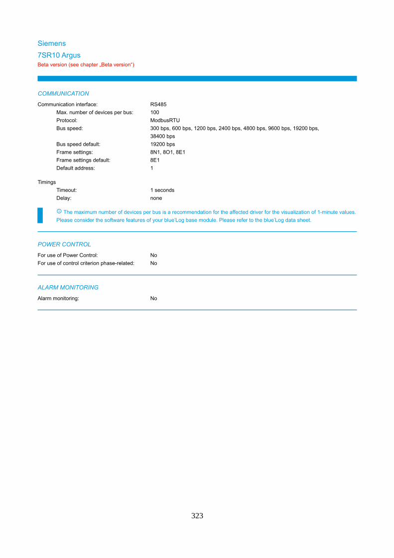
Siemens
7SR10 ArgusBeta version (see chapter „Beta version“)
COMMUNICATION
Communication interface: RS485
Max. number of devices per bus: 100
Protocol: ModbusRTU
Bus speed: 300 bps, 600 bps, 1200 bps, 2400 bps, 4800 bps, 9600 bps, 19200 bps,
38400 bps
Bus speed default: 19200 bps
Frame settings: 8N1, 8O1, 8E1
Frame settings default: 8E1
Default address: 1
Timings
Timeout: 1 seconds
Delay: none
The maximum number of devices per bus is a recommendation for the affected driver for the visualization of 1-minute values.
Please consider the software features of your blue’Log base module. Please refer to the blue’Log data sheet.
POWER CONTROL
For use of Power Control: No
For use of control criterion phase-related: No
ALARM MONITORING
Alarm monitoring: No
323
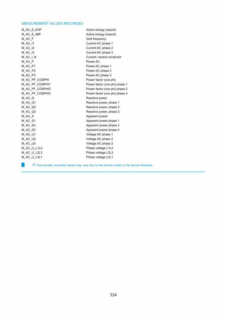
MEASUREMENT VALUES RECORDED
M_AC_E_EXP Active energy (export)
M_AC_E_IMP Active energy (import)
M_AC_F Grid frequency
M_AC_I1 Current AC phase 1
M_AC_I2 Current AC phase 2
M_AC_I3 Current AC phase 3
M_AC_I_N Current, neutral conductor
M_AC_P Power AC
M_AC_P1 Power AC phase 1
M_AC_P2 Power AC phase 2
M_AC_P3 Power AC phase 3
M_AC_PF_COSPHI Power factor (cos phi)
M_AC_PF_COSPHI1 Power factor (cos phi) phase 1
M_AC_PF_COSPHI2 Power factor (cos phi) phase 2
M_AC_PF_COSPHI3 Power factor (cos phi) phase 3
M_AC_Q Reactive power
M_AC_Q1 Reactive power, phase 1
M_AC_Q2 Reactive power, phase 2
M_AC_Q3 Reactive power, phase 3
M_AC_S Apparent power
M_AC_S1 Apparent power phase 1
M_AC_S2 Apparent power phase 2
M_AC_S3 Apparent power phase 3
M_AC_U1 Voltage AC phase 1
M_AC_U2 Voltage AC phase 2
M_AC_U3 Voltage AC phase 3
M_AC_U_L1L2 Phase voltage L1L2
M_AC_U_L2L3 Phase voltage L2L3
M_AC_U_L3L1 Phase voltage L3L1
The actually recorded values may vary due to the device model or the device firmware.
324
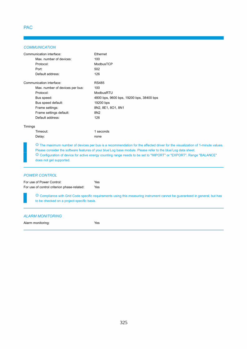
PAC
COMMUNICATION
Communication interface: Ethernet
Max. number of devices: 100
Protocol: ModbusTCP
Port: 502
Default address: 126
Communication interface: RS485
Max. number of devices per bus: 100
Protocol: ModbusRTU
Bus speed: 4800 bps, 9600 bps, 19200 bps, 38400 bps
Bus speed default: 19200 bps
Frame settings: 8N2, 8E1, 8O1, 8N1
Frame settings default: 8N2
Default address: 126
Timings
Timeout: 1 seconds
Delay: none
The maximum number of devices per bus is a recommendation for the affected driver for the visualization of 1-minute values.
Please consider the software features of your blue’Log base module. Please refer to the blue’Log data sheet.
Configuration of device for active energy counting range needs to be set to "IMPORT" or "EXPORT". Range "BALANCE"
does not get supported.
POWER CONTROL
For use of Power Control: Yes
For use of control criterion phase-related: Yes
Compliance with Grid Code specific requirements using this measuring instrument cannot be guaranteed in general, but has
to be checked on a project-specific basis.
ALARM MONITORING
Alarm monitoring: Yes
325
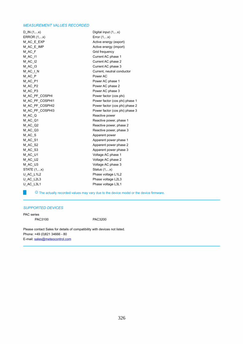
MEASUREMENT VALUES RECORDED
D_IN (1,...x) Digital input (1,...x)
ERROR (1,...x) Error (1,...x)
M_AC_E_EXP Active energy (export)
M_AC_E_IMP Active energy (import)
M_AC_F Grid frequency
M_AC_I1 Current AC phase 1
M_AC_I2 Current AC phase 2
M_AC_I3 Current AC phase 3
M_AC_I_N Current, neutral conductor
M_AC_P Power AC
M_AC_P1 Power AC phase 1
M_AC_P2 Power AC phase 2
M_AC_P3 Power AC phase 3
M_AC_PF_COSPHI Power factor (cos phi)
M_AC_PF_COSPHI1 Power factor (cos phi) phase 1
M_AC_PF_COSPHI2 Power factor (cos phi) phase 2
M_AC_PF_COSPHI3 Power factor (cos phi) phase 3
M_AC_Q Reactive power
M_AC_Q1 Reactive power, phase 1
M_AC_Q2 Reactive power, phase 2
M_AC_Q3 Reactive power, phase 3
M_AC_S Apparent power
M_AC_S1 Apparent power phase 1
M_AC_S2 Apparent power phase 2
M_AC_S3 Apparent power phase 3
M_AC_U1 Voltage AC phase 1
M_AC_U2 Voltage AC phase 2
M_AC_U3 Voltage AC phase 3
STATE (1,...x) Status (1,...x)
U_AC_L1L2 Phase voltage L1L2
U_AC_L2L3 Phase voltage L2L3
U_AC_L3L1 Phase voltage L3L1
The actually recorded values may vary due to the device model or the device firmware.
SUPPORTED DEVICES
PAC series
PAC3100 PAC3200
Please contact Sales for details of compatibility with devices not listed.
Phone: +49 (0)821 34666 - 80
E-mail: [email protected]
326
SunSpec Alliance
Compatible meter
COMMUNICATION
Communication interface: Ethernet
Max. number of devices: 100
Protocol: ModbusTCP
Port: 502
Default address: 1
Communication interface: RS485
Max. number of devices per bus: 98
Protocol: ModbusRTU
Bus speed: 9600 bps, 19200 bps, 38400 bps, 57600 bps, 115200 bps
Bus speed default: 9600 bps
Frame settings: 8N1
Frame settings default: 8N1
Default address: 1
Timings
Timeout: 1 seconds
Delay: none
The maximum number of devices per bus is a recommendation for the affected driver for the visualization of 1-minute values.
Please consider the software features of your blue’Log base module. Please refer to the blue’Log data sheet.
POWER CONTROL
For use of Power Control: No
For use of control criterion phase-related: No
ALARM MONITORING
Alarm monitoring: Yes
MEASUREMENT VALUES RECORDED
Model 201 Model 202 Model 203
Model 204
The actually recorded values may vary due to the device model or the device firmware.
327
Takemoto Denki
XM2-110
COMMUNICATION
Communication interface: RS485
Max. number of devices per bus: 100
Protocol: ModbusRTU
Bus speed: 1200 bps, 2400 bps, 4800 bps, 9600 bps, 19200 bps
Bus speed default: 9600 bps
Frame settings: 8E1, 8N1, 8O1, 8E2, 8N2, 8O2
Frame settings default: 8N1
Default address: 1
Timings
Timeout: 1 seconds
Delay: none
The maximum number of devices per bus is a recommendation for the affected driver for the visualization of 1-minute values.
Please consider the software features of your blue’Log base module. Please refer to the blue’Log data sheet.
The driver supports the address range 1 to 247. The address 0 does not get supported.
POWER CONTROL
For use of Power Control: No
For use of control criterion phase-related: No
ALARM MONITORING
Alarm monitoring: No
MEASUREMENT VALUES RECORDED
D_IN (1,...x) Digital input (1,...x)
M_AC_EQ_CAP_EXP Reactive energy (capacitive export)
M_AC_EQ_CAP_IMP Reactive energy (capacitive import)
M_AC_EQ_IND_EXP Reactive energy (inductive export)
M_AC_EQ_IND_IMP Reactive energy (inductive import)
M_AC_E_EXP Active energy (export)
M_AC_E_IMP Active energy (import)
M_AC_F Grid frequency
M_AC_I1 Current AC phase 1
M_AC_I2 Current AC phase 2
M_AC_I3 Current AC phase 3
M_AC_I_N Current, neutral conductor
M_AC_P Power AC
M_AC_PF_COSPHI Power factor (cos phi)
M_AC_Q Reactive power
M_AC_U1 Voltage AC phase 1
M_AC_U2 Voltage AC phase 2
M_AC_U3 Voltage AC phase 3
M_AC_U_L1L2 Phase voltage L1L2
M_AC_U_L2L3 Phase voltage L2L3
M_AC_U_L3L1 Phase voltage L3L1
328

The actually recorded values may vary due to the device model or the device firmware.
329
Vendor-neutral
S0 energy meter
COMMUNICATION
Communication interface: Digital Input (DI), Multi Input (MI)
Timings
Timeout: 2 seconds
Delay: none
The maximum number of devices per bus is a recommendation for the affected driver for the visualization of 1-minute values.
Please consider the software features of your blue’Log base module. Please refer to the blue’Log data sheet.
POWER CONTROL
For use of Power Control: No
For use of control criterion phase-related: No
ALARM MONITORING
Alarm monitoring: No
MEASUREMENT VALUES RECORDED
E_INT Energy generated per interval
The actually recorded values may vary due to the device model or the device firmware.
330
Veris Industries
E51C2
COMMUNICATION
Communication interface: Ethernet
Max. number of devices: 100
Protocol: ModbusTCP
Port: 502
Default address: 1
Communication interface: RS485
Max. number of devices per bus: 98
Protocol: ModbusRTU
Bus speed: 9600 bps, 19200 bps, 38400 bps, 57600 bps, 115200 bps
Bus speed default: 9600 bps
Frame settings: 8N1
Frame settings default: 8N1
Default address: 1
Timings
Timeout: 1 seconds
Delay: none
The maximum number of devices per bus is a recommendation for the affected driver for the visualization of 1-minute values.
Please consider the software features of your blue’Log base module. Please refer to the blue’Log data sheet.
POWER CONTROL
For use of Power Control: No
For use of control criterion phase-related: No
ALARM MONITORING
Alarm monitoring: Yes
MEASUREMENT VALUES RECORDED
Model 201 Model 202 Model 203
Model 204
The actually recorded values may vary due to the device model or the device firmware.
331
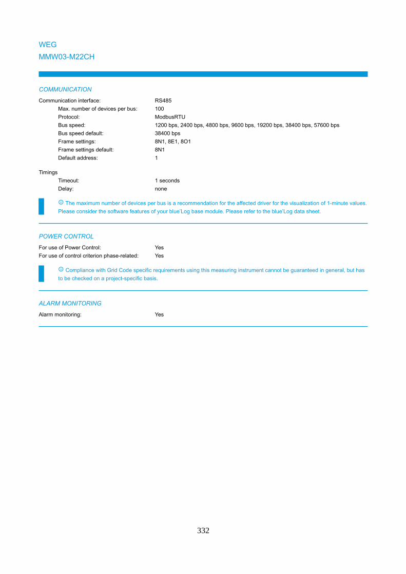
WEG
MMW03-M22CH
COMMUNICATION
Communication interface: RS485
Max. number of devices per bus: 100
Protocol: ModbusRTU
Bus speed: 1200 bps, 2400 bps, 4800 bps, 9600 bps, 19200 bps, 38400 bps, 57600 bps
Bus speed default: 38400 bps
Frame settings: 8N1, 8E1, 8O1
Frame settings default: 8N1
Default address: 1
Timings
Timeout: 1 seconds
Delay: none
The maximum number of devices per bus is a recommendation for the affected driver for the visualization of 1-minute values.
Please consider the software features of your blue’Log base module. Please refer to the blue’Log data sheet.
POWER CONTROL
For use of Power Control: Yes
For use of control criterion phase-related: Yes
Compliance with Grid Code specific requirements using this measuring instrument cannot be guaranteed in general, but has
to be checked on a project-specific basis.
ALARM MONITORING
Alarm monitoring: Yes
332
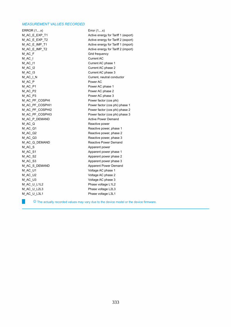
MEASUREMENT VALUES RECORDED
ERROR (1,...x) Error (1,...x)
M_AC_E_EXP_T1 Active energy for Tariff 1 (export)
M_AC_E_EXP_T2 Active energy for Tariff 2 (export)
M_AC_E_IMP_T1 Active energy for Tariff 1 (import)
M_AC_E_IMP_T2 Active energy for Tariff 2 (import)
M_AC_F Grid frequency
M_AC_I Current AC
M_AC_I1 Current AC phase 1
M_AC_I2 Current AC phase 2
M_AC_I3 Current AC phase 3
M_AC_I_N Current, neutral conductor
M_AC_P Power AC
M_AC_P1 Power AC phase 1
M_AC_P2 Power AC phase 2
M_AC_P3 Power AC phase 3
M_AC_PF_COSPHI Power factor (cos phi)
M_AC_PF_COSPHI1 Power factor (cos phi) phase 1
M_AC_PF_COSPHI2 Power factor (cos phi) phase 2
M_AC_PF_COSPHI3 Power factor (cos phi) phase 3
M_AC_P_DEMAND Active Power Demand
M_AC_Q Reactive power
M_AC_Q1 Reactive power, phase 1
M_AC_Q2 Reactive power, phase 2
M_AC_Q3 Reactive power, phase 3
M_AC_Q_DEMAND Reactive Power Demand
M_AC_S Apparent power
M_AC_S1 Apparent power phase 1
M_AC_S2 Apparent power phase 2
M_AC_S3 Apparent power phase 3
M_AC_S_DEMAND Apparent Power Demand
M_AC_U1 Voltage AC phase 1
M_AC_U2 Voltage AC phase 2
M_AC_U3 Voltage AC phase 3
M_AC_U_L1L2 Phase voltage L1L2
M_AC_U_L2L3 Phase voltage L2L3
M_AC_U_L3L1 Phase voltage L3L1
The actually recorded values may vary due to the device model or the device firmware.
333
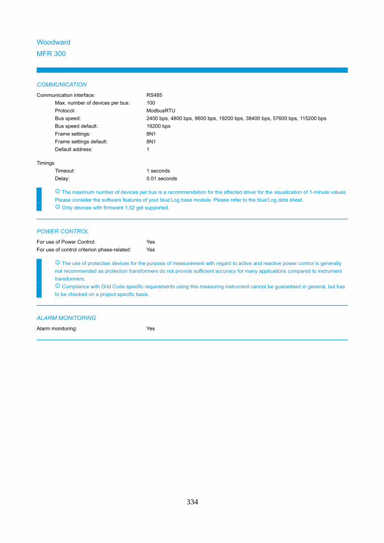
Woodward
MFR 300
COMMUNICATION
Communication interface: RS485
Max. number of devices per bus: 100
Protocol: ModbusRTU
Bus speed: 2400 bps, 4800 bps, 9600 bps, 19200 bps, 38400 bps, 57600 bps, 115200 bps
Bus speed default: 19200 bps
Frame settings: 8N1
Frame settings default: 8N1
Default address: 1
Timings
Timeout: 1 seconds
Delay: 0.01 seconds
The maximum number of devices per bus is a recommendation for the affected driver for the visualization of 1-minute values.
Please consider the software features of your blue’Log base module. Please refer to the blue’Log data sheet.
Only devices with firmware 1.02 get supported.
POWER CONTROL
For use of Power Control: Yes
For use of control criterion phase-related: Yes
The use of protection devices for the purpose of measurement with regard to active and reactive power control is generally
not recommended as protection transformers do not provide sufficient accuracy for many applications compared to instrument
transformers.
Compliance with Grid Code specific requirements using this measuring instrument cannot be guaranteed in general, but has
to be checked on a project-specific basis.
ALARM MONITORING
Alarm monitoring: Yes
334
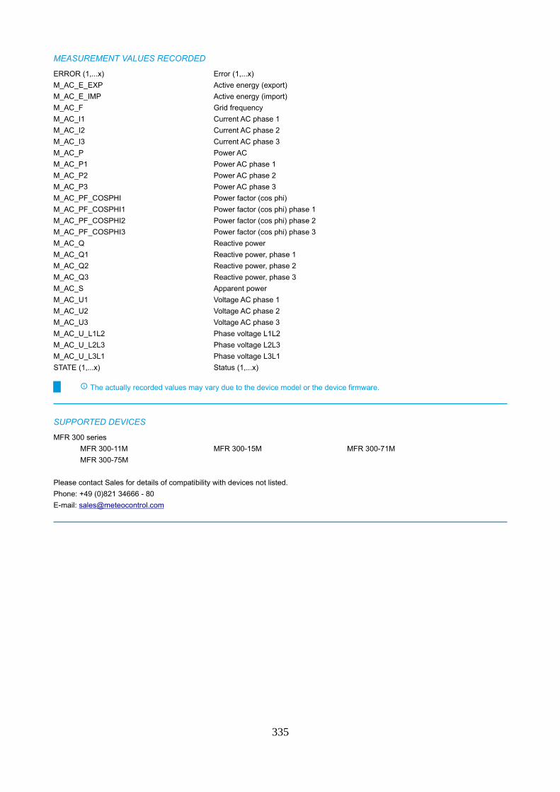
MEASUREMENT VALUES RECORDED
ERROR (1,...x) Error (1,...x)
M_AC_E_EXP Active energy (export)
M_AC_E_IMP Active energy (import)
M_AC_F Grid frequency
M_AC_I1 Current AC phase 1
M_AC_I2 Current AC phase 2
M_AC_I3 Current AC phase 3
M_AC_P Power AC
M_AC_P1 Power AC phase 1
M_AC_P2 Power AC phase 2
M_AC_P3 Power AC phase 3
M_AC_PF_COSPHI Power factor (cos phi)
M_AC_PF_COSPHI1 Power factor (cos phi) phase 1
M_AC_PF_COSPHI2 Power factor (cos phi) phase 2
M_AC_PF_COSPHI3 Power factor (cos phi) phase 3
M_AC_Q Reactive power
M_AC_Q1 Reactive power, phase 1
M_AC_Q2 Reactive power, phase 2
M_AC_Q3 Reactive power, phase 3
M_AC_S Apparent power
M_AC_U1 Voltage AC phase 1
M_AC_U2 Voltage AC phase 2
M_AC_U3 Voltage AC phase 3
M_AC_U_L1L2 Phase voltage L1L2
M_AC_U_L2L3 Phase voltage L2L3
M_AC_U_L3L1 Phase voltage L3L1
STATE (1,...x) Status (1,...x)
The actually recorded values may vary due to the device model or the device firmware.
SUPPORTED DEVICES
MFR 300 series
MFR 300-11M MFR 300-15M MFR 300-71M
MFR 300-75M
Please contact Sales for details of compatibility with devices not listed.
Phone: +49 (0)821 34666 - 80
E-mail: [email protected]
335
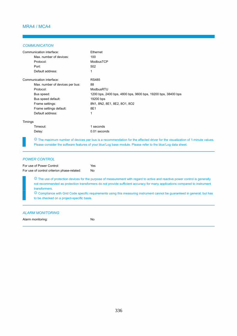
MRA4 / MCA4
COMMUNICATION
Communication interface: Ethernet
Max. number of devices: 100
Protocol: ModbusTCP
Port: 502
Default address: 1
Communication interface: RS485
Max. number of devices per bus: 88
Protocol: ModbusRTU
Bus speed: 1200 bps, 2400 bps, 4800 bps, 9600 bps, 19200 bps, 38400 bps
Bus speed default: 19200 bps
Frame settings: 8N1, 8N2, 8E1, 8E2, 8O1, 8O2
Frame settings default: 8E1
Default address: 1
Timings
Timeout: 1 seconds
Delay: 0.01 seconds
The maximum number of devices per bus is a recommendation for the affected driver for the visualization of 1-minute values.
Please consider the software features of your blue’Log base module. Please refer to the blue’Log data sheet.
POWER CONTROL
For use of Power Control: Yes
For use of control criterion phase-related: No
The use of protection devices for the purpose of measurement with regard to active and reactive power control is generally
not recommended as protection transformers do not provide sufficient accuracy for many applications compared to instrument
transformers.
Compliance with Grid Code specific requirements using this measuring instrument cannot be guaranteed in general, but has
to be checked on a project-specific basis.
ALARM MONITORING
Alarm monitoring: No
336
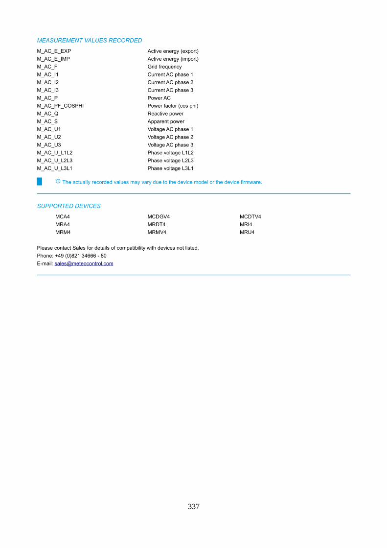
MEASUREMENT VALUES RECORDED
M_AC_E_EXP Active energy (export)
M_AC_E_IMP Active energy (import)
M_AC_F Grid frequency
M_AC_I1 Current AC phase 1
M_AC_I2 Current AC phase 2
M_AC_I3 Current AC phase 3
M_AC_P Power AC
M_AC_PF_COSPHI Power factor (cos phi)
M_AC_Q Reactive power
M_AC_S Apparent power
M_AC_U1 Voltage AC phase 1
M_AC_U2 Voltage AC phase 2
M_AC_U3 Voltage AC phase 3
M_AC_U_L1L2 Phase voltage L1L2
M_AC_U_L2L3 Phase voltage L2L3
M_AC_U_L3L1 Phase voltage L3L1
The actually recorded values may vary due to the device model or the device firmware.
SUPPORTED DEVICES
MCA4 MCDGV4 MCDTV4
MRA4 MRDT4 MRI4
MRM4 MRMV4 MRU4
Please contact Sales for details of compatibility with devices not listed.
Phone: +49 (0)821 34666 - 80
E-mail: [email protected]
337
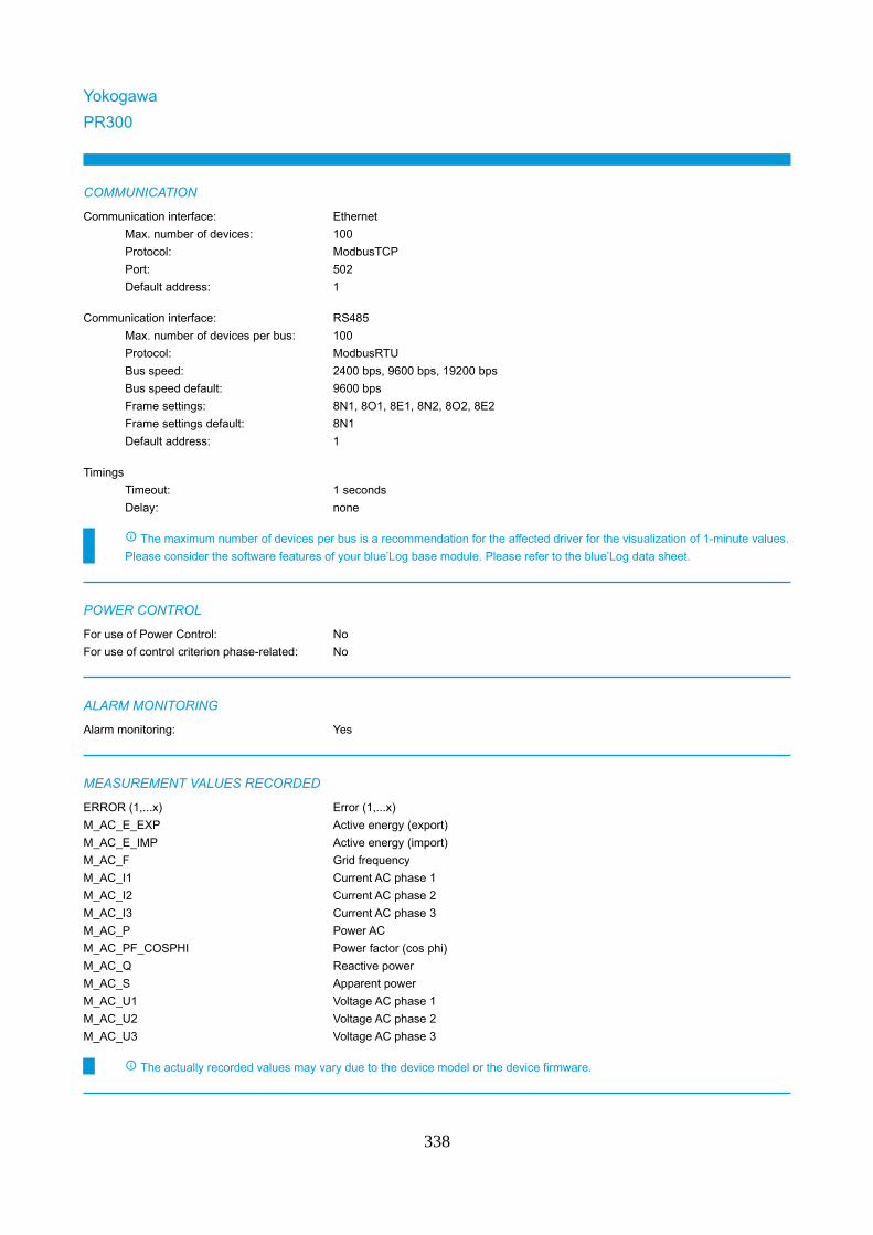
Yokogawa
PR300
COMMUNICATION
Communication interface: Ethernet
Max. number of devices: 100
Protocol: ModbusTCP
Port: 502
Default address: 1
Communication interface: RS485
Max. number of devices per bus: 100
Protocol: ModbusRTU
Bus speed: 2400 bps, 9600 bps, 19200 bps
Bus speed default: 9600 bps
Frame settings: 8N1, 8O1, 8E1, 8N2, 8O2, 8E2
Frame settings default: 8N1
Default address: 1
Timings
Timeout: 1 seconds
Delay: none
The maximum number of devices per bus is a recommendation for the affected driver for the visualization of 1-minute values.
Please consider the software features of your blue’Log base module. Please refer to the blue’Log data sheet.
POWER CONTROL
For use of Power Control: No
For use of control criterion phase-related: No
ALARM MONITORING
Alarm monitoring: Yes
MEASUREMENT VALUES RECORDED
ERROR (1,...x) Error (1,...x)
M_AC_E_EXP Active energy (export)
M_AC_E_IMP Active energy (import)
M_AC_F Grid frequency
M_AC_I1 Current AC phase 1
M_AC_I2 Current AC phase 2
M_AC_I3 Current AC phase 3
M_AC_P Power AC
M_AC_PF_COSPHI Power factor (cos phi)
M_AC_Q Reactive power
M_AC_S Apparent power
M_AC_U1 Voltage AC phase 1
M_AC_U2 Voltage AC phase 2
M_AC_U3 Voltage AC phase 3
The actually recorded values may vary due to the device model or the device firmware.
338
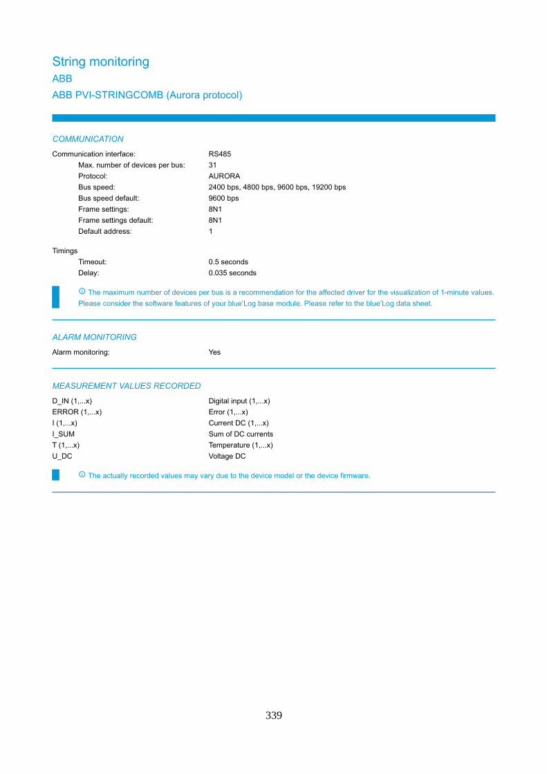
String monitoringABB
ABB PVI-STRINGCOMB (Aurora protocol)
COMMUNICATION
Communication interface: RS485
Max. number of devices per bus: 31
Protocol: AURORA
Bus speed: 2400 bps, 4800 bps, 9600 bps, 19200 bps
Bus speed default: 9600 bps
Frame settings: 8N1
Frame settings default: 8N1
Default address: 1
Timings
Timeout: 0.5 seconds
Delay: 0.035 seconds
The maximum number of devices per bus is a recommendation for the affected driver for the visualization of 1-minute values.
Please consider the software features of your blue’Log base module. Please refer to the blue’Log data sheet.
ALARM MONITORING
Alarm monitoring: Yes
MEASUREMENT VALUES RECORDED
D_IN (1,...x) Digital input (1,...x)
ERROR (1,...x) Error (1,...x)
I (1,...x) Current DC (1,...x)
I_SUM Sum of DC currents
T (1,...x) Temperature (1,...x)
U_DC Voltage DC
The actually recorded values may vary due to the device model or the device firmware.
339
Ultra Solar Field GatheringBeta version (see chapter „Beta version“)
COMMUNICATION
Communication interface: RS485
Max. number of devices per bus: 100
Protocol: ModbusRTU
Bus speed: 19200 bps
Bus speed default: 19200 bps
Frame settings: 8N1
Frame settings default: 8N1
Default address: 2
Timings
Timeout: 5 seconds
Delay: none
The maximum number of devices per bus is a recommendation for the affected driver for the visualization of 1-minute values.
Please consider the software features of your blue’Log base module. Please refer to the blue’Log data sheet.
ALARM MONITORING
Alarm monitoring: Yes
MEASUREMENT VALUES RECORDED
D_IN Digital input
I (1,...x) Current DC (1,...x)
I_SUM Sum of DC currents
STATE (1,...x) Status (1,...x)
T Temperature
U_DC Voltage DC
The actually recorded values may vary due to the device model or the device firmware.
SUPPORTED DEVICES
ULTRA series
3G90 3L11 V11
Please contact Sales for details of compatibility with devices not listed.
Phone: +49 (0)821 34666 - 80
E-mail: [email protected]
340
AROS (Riello)
String BoxBeta version (see chapter „Beta version“)
COMMUNICATION
Communication interface: RS485
Max. number of devices per bus: 100
Protocol: ModbusRTU
Bus speed: 9600 bps
Bus speed default: 9600 bps
Frame settings: 8N1
Frame settings default: 8N1
Default address: 1
Timings
Timeout: 1 seconds
Delay: none
The maximum number of devices per bus is a recommendation for the affected driver for the visualization of 1-minute values.
Please consider the software features of your blue’Log base module. Please refer to the blue’Log data sheet.
ALARM MONITORING
Alarm monitoring: No
MEASUREMENT VALUES RECORDED
I (1,...x) Current DC (1,...x)
T (1,...x) Temperature (1,...x)
U_DC Voltage DC
The actually recorded values may vary due to the device model or the device firmware.
341
Carlo Gavazzi
VMU
COMMUNICATION
Communication interface: RS485
Max. number of devices per bus: 100
Protocol: ModbusRTU
Bus speed: 9600 bps, 19200 bps, 38400 bps, 115200 bps
Bus speed default: 9600 bps
Frame settings: 8N1, 8E1, 8O1
Frame settings default: 8N1
Default address: 1
Timings
Timeout: 1 seconds
Delay: none
The maximum number of devices per bus is a recommendation for the affected driver for the visualization of 1-minute values.
Please consider the software features of your blue’Log base module. Please refer to the blue’Log data sheet.
ALARM MONITORING
Alarm monitoring: Yes
MEASUREMENT VALUES RECORDED
D_IN (1,...x) Digital input (1,...x)
ERROR (1,...x) Error (1,...x)
I (1,...x) Current DC (1,...x)
STATE (1,...x) Status (1,...x)
T (1,...x) Temperature (1,...x)
The actually recorded values may vary due to the device model or the device firmware.
SUPPORTED DEVICES
VMU-M VMU-S VMU-S30
Please contact Sales for details of compatibility with devices not listed.
Phone: +49 (0)821 34666 - 80
E-mail: [email protected]
342
Chint
CPS CB10
COMMUNICATION
Communication interface: RS485
Max. number of devices per bus: 100
Protocol: ModbusRTU
Bus speed: 2400 bps, 4800 bps, 9600 bps, 19200 bps, 38400 bps
Bus speed default: 9600 bps
Frame settings: 8N1, 8O1, 8E1
Frame settings default: 8N1
Default address: 1
Timings
Timeout: 1 seconds
Delay: 0.1 seconds
The maximum number of devices per bus is a recommendation for the affected driver for the visualization of 1-minute values.
Please consider the software features of your blue’Log base module. Please refer to the blue’Log data sheet.
ALARM MONITORING
Alarm monitoring: No
MEASUREMENT VALUES RECORDED
I (1,...x) Current DC (1,...x)
I_SUM Sum of DC currents
P_DC Power DC
STATE (1,...x) Status (1,...x)
T (1,...x) Temperature (1,...x)
U_DC Voltage DC
The actually recorded values may vary due to the device model or the device firmware.
343
Circutor
TR8
COMMUNICATION
Communication interface: Ethernet
Max. number of devices: 100
Protocol: ModbusTCP
Port: 502
Default address: 1
Communication interface: RS485
Max. number of devices per bus: 100
Protocol: ModbusRTU
Bus speed: 9600 bps, 19200 bps, 38400 bps
Bus speed default: 9600 bps
Frame settings: 8N1
Frame settings default: 8N1
Default address: 1
Timings
Timeout: 1 seconds
Delay: none
The maximum number of devices per bus is a recommendation for the affected driver for the visualization of 1-minute values.
Please consider the software features of your blue’Log base module. Please refer to the blue’Log data sheet.
Driver supports 'single slave' devices only, the modus 'Slave-Subslave' is not supported. For this reason, the maximum of
these stringboxes on a single bus is limited to 32.
ALARM MONITORING
Alarm monitoring: No
MEASUREMENT VALUES RECORDED
D_IN (1,...x) Digital input (1,...x)
I (1,...x) Current DC (1,...x)
U_DC Voltage DC
The actually recorded values may vary due to the device model or the device firmware.
344
TR16Beta version (see chapter „Beta version“)
COMMUNICATION
Communication interface: Ethernet
Max. number of devices: 100
Protocol: ModbusTCP
Port: 502
Default address: 1
Communication interface: RS485
Max. number of devices per bus: 100
Protocol: ModbusRTU
Bus speed: 9600 bps, 19200 bps, 38400 bps
Bus speed default: 9600 bps
Frame settings: 8N1
Frame settings default: 8N1
Default address: 1
Timings
Timeout: 1 seconds
Delay: none
The maximum number of devices per bus is a recommendation for the affected driver for the visualization of 1-minute values.
Please consider the software features of your blue’Log base module. Please refer to the blue’Log data sheet.
ALARM MONITORING
Alarm monitoring: No
MEASUREMENT VALUES RECORDED
D_IN (1,...x) Digital input (1,...x)
I (1,...x) Current DC (1,...x)
T (1,...x) Temperature (1,...x)
U_DC Voltage DC
The actually recorded values may vary due to the device model or the device firmware.
345
Gantner
string.bloxx 1xx EM 1500V
COMMUNICATION
Communication interface: RS485
Max. number of devices per bus: 44
Protocol: ModbusRTU
Bus speed: 1200 bps, 2400 bps, 4800 bps, 9600 bps, 19200 bps, 38400 bps
Bus speed default: 19200 bps
Frame settings: 8N1, 8E1, 8O1
Frame settings default: 8N1
Default address: 1
Timings
Timeout: 5 seconds
Delay: 0.5 seconds
The maximum number of devices per bus is a recommendation for the affected driver for the visualization of 1-minute values.
Please consider the software features of your blue’Log base module. Please refer to the blue’Log data sheet.
ALARM MONITORING
Alarm monitoring: No
MEASUREMENT VALUES RECORDED
D_IN (1,...x) Digital input (1,...x)
I (1,...x) Current DC (1,...x)
I_SUM Sum of DC currents
P_DC Power DC
T (1,...x) Temperature (1,...x)
U_DC Voltage DC
The actually recorded values may vary due to the device model or the device firmware.
SUPPORTED DEVICES
string.bloxx 116 EM 1500V series
string.bloxx 116 EM 1500V
string.bloxx 124 EM 1500V series
string.bloxx 124 EM 1500V
Please note the string.bloxx 116 EM with 32 string inputs consists of two 16 string input versions. For a correct scan the two
devices need to be scanned separately (1 x string.bloxx 116 EM with 32 string inputs = 2 devices each with its own bus
address).
Please contact Sales for details of compatibility with devices not listed.
Phone: +49 (0)821 34666 - 80
E-mail: [email protected]
346
KACO new energy
blueplanet Argus (SunSpec)
COMMUNICATION
Communication interface: Ethernet
Max. number of devices: 100
Protocol: ModbusTCP
Port: 502
Default address: 11
Communication interface: RS485
Max. number of devices per bus: 100
Protocol: ModbusRTU
Bus speed: 9600 bps, 19200 bps, 38400 bps, 57600 bps, 115200 bps
Bus speed default: 38400 bps
Frame settings: 8N1
Frame settings default: 8N1
Default address: 1
Timings
Timeout: 1 seconds
Delay: none
The maximum number of devices per bus is a recommendation for the affected driver for the visualization of 1-minute values.
Please consider the software features of your blue’Log base module. Please refer to the blue’Log data sheet.
ALARM MONITORING
Alarm monitoring: Yes
MEASUREMENT VALUES RECORDED
Model 401 Model 402 Model 403
Model 404
The actually recorded values may vary due to the device model or the device firmware.
SUPPORTED DEVICES
blueplanet Argus series
blueplanet Argus L-20 blueplanet Argus L-24 blueplanet Argus XL-20
blueplanet Argus XL-24
Please contact Sales for details of compatibility with devices not listed.
Phone: +49 (0)821 34666 - 80
E-mail: [email protected]
347
Powador Argus 16/24S DCS
COMMUNICATION
Communication interface: RS485
Max. number of devices per bus: 100
Protocol: KACO
Bus speed: 9600 bps
Bus speed default: 9600 bps
Frame settings: 8N1
Frame settings default: 8N1
Default address: 1
Timings
Timeout: 1 seconds
Delay: 0.03 seconds
The maximum number of devices per bus is a recommendation for the affected driver for the visualization of 1-minute values.
Please consider the software features of your blue’Log base module. Please refer to the blue’Log data sheet.
ALARM MONITORING
Alarm monitoring: No
MEASUREMENT VALUES RECORDED
I (1,...x) Current DC (1,...x)
The actually recorded values may vary due to the device model or the device firmware.
SUPPORTED DEVICES
Powador Argus series
Powador Argus 16S DCS Powador Argus 24S DCS
Please contact Sales for details of compatibility with devices not listed.
Phone: +49 (0)821 34666 - 80
E-mail: [email protected]
348
Kernel sistemi
ST1xxxx
COMMUNICATION
Communication interface: Ethernet
Max. number of devices: 100
Protocol: ModbusTCP
Port: 502
Default address: 1
Communication interface: RS485
Max. number of devices per bus: 100
Protocol: ModbusRTU
Bus speed: 9600 bps, 19200 bps
Bus speed default: 9600 bps
Frame settings: 8E1, 8N1
Frame settings default: 8N1
Default address: 1
Timings
Timeout: 1 seconds
Delay: none
The maximum number of devices per bus is a recommendation for the affected driver for the visualization of 1-minute values.
Please consider the software features of your blue’Log base module. Please refer to the blue’Log data sheet.
ALARM MONITORING
Alarm monitoring: No
MEASUREMENT VALUES RECORDED
D_IN (1,...x) Digital input (1,...x)
I (1,...x) Current DC (1,...x)
I_SUM Sum of DC currents
P_DC Power DC
T (1,...x) Temperature (1,...x)
U_DC Voltage DC
The actually recorded values may vary due to the device model or the device firmware.
SUPPORTED DEVICES
ST1 Series series
ST1 0630 ST1 0830 ST1 1030
ST1 1430 ST1 1630 ST1 2422
Please contact Sales for details of compatibility with devices not listed.
Phone: +49 (0)821 34666 - 80
E-mail: [email protected]
349
Klein
KSM-VX.X
COMMUNICATION
Communication interface: RS485
Max. number of devices per bus: 100
Protocol: ModbusRTU
Bus speed: 19200 bps
Bus speed default: 19200 bps
Frame settings: 8N1
Frame settings default: 8N1
Default address: 1
Timings
Timeout: 1 seconds
Delay: none
The maximum number of devices per bus is a recommendation for the affected driver for the visualization of 1-minute values.
Please consider the software features of your blue’Log base module. Please refer to the blue’Log data sheet.
ALARM MONITORING
Alarm monitoring: No
MEASUREMENT VALUES RECORDED
D_IN (1,...x) Digital input (1,...x)
I (1,...x) Current DC (1,...x)
I_SUM Sum of DC currents
P_DC Power DC
T (1,...x) Temperature (1,...x)
U_DC Voltage DC
The actually recorded values may vary due to the device model or the device firmware.
SUPPORTED DEVICES
KSM-V0.7 KSM-V0.8
Please contact Sales for details of compatibility with devices not listed.
Phone: +49 (0)821 34666 - 80
E-mail: [email protected]
350
meteocontrol
i´catcher
COMMUNICATION
Communication interface: RS485
Max. number of devices per bus: 44
Protocol: ModbusRTU
Bus speed: 2400 bps, 4800 bps, 9600 bps, 19200 bps
Bus speed default: 19200 bps
Frame settings: 8N1, 8E1, 8O1
Frame settings default: 8N1
Default address: 1
Timings
Timeout: 5 seconds
Delay: 0.5 seconds
The maximum number of devices per bus is a recommendation for the affected driver for the visualization of 1-minute values.
Please consider the software features of your blue’Log base module. Please refer to the blue’Log data sheet.
ALARM MONITORING
Alarm monitoring: No
MEASUREMENT VALUES RECORDED
D_IN (1,...x) Digital input (1,...x)
I (1,...x) Current DC (1,...x)
I_SUM Sum of DC currents
P_DC Power DC
T (1,...x) Temperature (1,...x)
U_DC Voltage DC
The actually recorded values may vary due to the device model or the device firmware.
SUPPORTED DEVICES
i´catcher series
i´catcher 8-1B i´catcher 16-1B i´catcher 24-1B
Please contact Sales for details of compatibility with devices not listed.
Phone: +49 (0)821 34666 - 80
E-mail: [email protected]
351
String Monitoring Unit (Kernel Sistemi ST2xxxx)
COMMUNICATION
Communication interface: Ethernet
Max. number of devices: 100
Protocol: ModbusTCP
Port: 502
Default address: 1
Communication interface: RS485
Max. number of devices per bus: 100
Protocol: ModbusRTU
Bus speed: 2400 bps, 4800 bps, 9600 bps, 19200 bps
Bus speed default: 9600 bps
Frame settings: 8N1, 8O1, 8E1
Frame settings default: 8N1
Default address: 1
Timings
Timeout: 1 seconds
Delay: none
The maximum number of devices per bus is a recommendation for the affected driver for the visualization of 1-minute values.
Please consider the software features of your blue’Log base module. Please refer to the blue’Log data sheet.
ALARM MONITORING
Alarm monitoring: No
MEASUREMENT VALUES RECORDED
D_IN (1,...x) Digital input (1,...x)
I (1,...x) Current DC (1,...x)
I_SUM Sum of DC currents
P_DC Power DC
T (1,...x) Temperature (1,...x)
U_DC Voltage DC
The actually recorded values may vary due to the device model or the device firmware.
SUPPORTED DEVICES
SMU 0825 SMU 1225 SMU 1625
SMU 2422
Please contact Sales for details of compatibility with devices not listed.
Phone: +49 (0)821 34666 - 80
E-mail: [email protected]
352
Monsol
1000|1500V Shunt
COMMUNICATION
Communication interface: RS485
Max. number of devices per bus: 100
Protocol: ModbusRTU
Bus speed: 9600 bps
Bus speed default: 9600 bps
Frame settings: 8N1
Frame settings default: 8N1
Default address: 1
Timings
Timeout: 1 seconds
Delay: none
The maximum number of devices per bus is a recommendation for the affected driver for the visualization of 1-minute values.
Please consider the software features of your blue’Log base module. Please refer to the blue’Log data sheet.
ALARM MONITORING
Alarm monitoring: No
MEASUREMENT VALUES RECORDED
D_IN (1,...x) Digital input (1,...x)
I (1,...x) Current DC (1,...x)
T Temperature
U_DC Voltage DC
The actually recorded values may vary due to the device model or the device firmware.
353
Noark
SUP 4S-20SBeta version (see chapter „Beta version“)
COMMUNICATION
Communication interface: RS485
Max. number of devices per bus: 17
Protocol: ModbusRTU
Bus speed: 2400 bps, 4800 bps, 9600 bps, 19200 bps
Bus speed default: 9600 bps
Frame settings: 8N1
Frame settings default: 8N1
Default address: 1
Timings
Timeout: 1 seconds
Delay: 0.5 seconds
The maximum number of devices per bus is a recommendation for the affected driver for the visualization of 1-minute values.
Please consider the software features of your blue’Log base module. Please refer to the blue’Log data sheet.
ALARM MONITORING
Alarm monitoring: Yes
MEASUREMENT VALUES RECORDED
ERROR (1,...x) Error (1,...x)
I (1,...x) Current DC (1,...x)
P_DC Power DC
STATE (1,...x) Status (1,...x)
T Temperature
U_DC Voltage DC
The actually recorded values may vary due to the device model or the device firmware.
354
Phoenix Contact
Solarcheck
COMMUNICATION
Communication interface: RS485
Max. number of devices per bus: 100
Protocol: ModbusRTU
Bus speed: 9600 bps, 19200 bps, 38400 bps
Bus speed default: 9600 bps
Frame settings: 8N1, 8N2, 8O1, 8O2, 8E1, 8E2
Frame settings default: 8N1
Default address: 1
Timings
Timeout: 1 seconds
Delay: none
The maximum number of devices per bus is a recommendation for the affected driver for the visualization of 1-minute values.
Please consider the software features of your blue’Log base module. Please refer to the blue’Log data sheet.
In order to measure voltage of the "voltage measuring module", it must be connected to the 8S module in the first channel.
Connection of the "voltage measuring module" to the 4S module not possible.
Depending on the amount of modules connected the total amount of devices varies that can be connected to one blue’Log (e.g.
8 x 8S modules = 8 devices for the blue’Log).
ALARM MONITORING
Alarm monitoring: Yes
MEASUREMENT VALUES RECORDED
D_IN (1,...x) Digital input (1,...x)
I (1,...x) Current DC (1,...x)
STATE (1,...x) Status (1,...x)
T (1,...x) Temperature (1,...x)
U_DC Voltage DC
The actually recorded values may vary due to the device model or the device firmware.
Values for "Status" and "Temperature" will just be available for the first module if modules (4S, 8S) get connected to the first
channel.
SUPPORTED DEVICES
SCK-C-MODBUS SCK-M-I-4S-20A SCK-M-I-8S-20A
Please contact Sales for details of compatibility with devices not listed.
Phone: +49 (0)821 34666 - 80
E-mail: [email protected]
355
Power Electronics
HE/HEC/HES Disconnecting UnitBeta version (see chapter „Beta version“)
COMMUNICATION
Communication interface: Ethernet
Max. number of devices: 100
Protocol: ModbusTCP
Port: 502
Default address: 1
Communication interface: RS485
Max. number of devices per bus: 100
Protocol: ModbusRTU
Bus speed: 600 bps, 1200 bps, 2400 bps, 4800 bps, 9600 bps, 19200 bps
Bus speed default: 9600 bps
Frame settings: 8N1
Frame settings default: 8N1
Default address: 1
Timings
Timeout: 5 seconds
Delay: none
The maximum number of devices per bus is a recommendation for the affected driver for the visualization of 1-minute values.
Please consider the software features of your blue’Log base module. Please refer to the blue’Log data sheet.
ALARM MONITORING
Alarm monitoring: No
MEASUREMENT VALUES RECORDED
I (1,...x) Current DC (1,...x)
U_DC Voltage DC
The actually recorded values may vary due to the device model or the device firmware.
356
Raycap
ProSMS
COMMUNICATION
Communication interface: RS485
Max. number of devices per bus: 100
Protocol: ModbusRTU
Bus speed: 2400 bps, 4800 bps, 9600 bps, 19200 bps, 38400 bps
Bus speed default: 38400 bps
Frame settings: 8E1, 8O1, 8N2
Frame settings default: 8E1
Default address: 5
Timings
Timeout: 1 seconds
Delay: none
The maximum number of devices per bus is a recommendation for the affected driver for the visualization of 1-minute values.
Please consider the software features of your blue’Log base module. Please refer to the blue’Log data sheet.
ALARM MONITORING
Alarm monitoring: No
MEASUREMENT VALUES RECORDED
D_IN (1,...x) Digital input (1,...x)
I (1,...x) Current DC (1,...x)
T Temperature
U_DC Voltage DC
The actually recorded values may vary due to the device model or the device firmware.
SUPPORTED DEVICES
ProSMS8-WM
ProSMS series
ProSMS 8 ProSMS 1500
When connecting the ProSMS 8-WM via the ProSMS-G it is neccessary to select Parity "ODD" on blue'Log XM / XC for a
succcessful scan.
Please contact Sales for details of compatibility with devices not listed.
Phone: +49 (0)821 34666 - 80
E-mail: [email protected]
357
Renovagy
PV5790 String Monitoring SystemBeta version (see chapter „Beta version“)
COMMUNICATION
Communication interface: Ethernet
Max. number of devices: 100
Protocol: ModbusTCP
Port: 502
Default address: 1
Communication interface: RS485
Max. number of devices per bus: 100
Protocol: ModbusRTU
Bus speed: 300 bps, 600 bps, 1200 bps, 2400 bps, 4800 bps, 9600 bps, 19200 bps,
38400 bps, 57600 bps, 115200 bps
Bus speed default: 9600 bps
Frame settings: 8E1, 8N1
Frame settings default: 8E1
Default address: 1
Timings
Timeout: 1 seconds
Delay: none
The maximum number of devices per bus is a recommendation for the affected driver for the visualization of 1-minute values.
Please consider the software features of your blue’Log base module. Please refer to the blue’Log data sheet.
ALARM MONITORING
Alarm monitoring: No
MEASUREMENT VALUES RECORDED
D_IN (1,...x) Digital input (1,...x)
I (1,...x) Current DC (1,...x)
T (1,...x) Temperature (1,...x)
U_DC Voltage DC
The actually recorded values may vary due to the device model or the device firmware.
358
Santerno
Smart String BoxBeta version (see chapter „Beta version“)
COMMUNICATION
Communication interface: Ethernet
Max. number of devices: 100
Protocol: ModbusTCP
Port: 502
Default address: 1
Communication interface: RS485
Max. number of devices per bus: 100
Protocol: ModbusRTU
Bus speed: 1200 bps, 2400 bps, 4800 bps, 9600 bps, 19200 bps, 38400 bps, 57600 bps
Bus speed default: 38400 bps
Frame settings: 8N1, 8N2, 8E1, 8O1
Frame settings default: 8N2
Default address: 1
Timings
Timeout: 1 seconds
Delay: 0.005 seconds
The maximum number of devices per bus is a recommendation for the affected driver for the visualization of 1-minute values.
Please consider the software features of your blue’Log base module. Please refer to the blue’Log data sheet.
Please note:
-The "SSB CS-SP 16 600V" consits of 2 x "SSB CS-SP 8 600V" (1 x SSB CS-SP 16 600V = 2 devices)
-The "SSB CS-SP 24 600V" consist of 3 x "SSB CS-SP 8 600V" (1 x SSB CS-SP 24 600V = 3 devices)
For a correct scan the devices need to be scanned separately (1 x SSB CS-SP 16 600V = 2 devices each with its own bus
address).
ALARM MONITORING
Alarm monitoring: Yes
MEASUREMENT VALUES RECORDED
ERROR (1,...x) Error (1,...x)
I (1,...x) Current DC (1,...x)
T Temperature
The actually recorded values may vary due to the device model or the device firmware.
SUPPORTED DEVICES
Smart String Box series
Santerno SSB CS-SP 8 600V Santerno SSB CS-SP 16 600V Santerno SSB CS-SP 24 600V
359

Please contact Sales for details of compatibility with devices not listed.
Phone: +49 (0)821 34666 - 80
E-mail: [email protected]
360
Sunway TG ES1008
COMMUNICATION
Communication interface: Ethernet
Max. number of devices: 100
Protocol: ModbusTCP
Port: 502
Default address: 1
Communication interface: RS485
Max. number of devices per bus: 100
Protocol: ModbusRTU
Bus speed: 1200 bps, 2400 bps, 4800 bps, 9600 bps, 19200 bps, 38400 bps, 57600 bps
Bus speed default: 38400 bps
Frame settings: 8N1, 8N2, 8E1, 8O1
Frame settings default: 8N2
Default address: 1
Timings
Timeout: 1 seconds
Delay: 0.005 seconds
The maximum number of devices per bus is a recommendation for the affected driver for the visualization of 1-minute values.
Please consider the software features of your blue’Log base module. Please refer to the blue’Log data sheet.
ALARM MONITORING
Alarm monitoring: Yes
MEASUREMENT VALUES RECORDED
D_IN (1,...x) Digital input (1,...x)
ERROR (1,...x) Error (1,...x)
I (1,...x) Current DC (1,...x)
I_SUM Sum of DC currents
T Temperature
The actually recorded values may vary due to the device model or the device firmware.
361
SENECA
Z-4AI SCB (0 to 25A)Beta version (see chapter „Beta version“)
COMMUNICATION
Communication interface: RS485
Max. number of devices per bus: 100
Protocol: ModbusRTU
Bus speed: 2400 bps, 4800 bps, 9600 bps, 19200 bps, 38400 bps
Bus speed default: 9600 bps
Frame settings: 8N1, 8E1, 8O1
Frame settings default: 8N1
Default address: 1
Timings
Timeout: 1 seconds
Delay: none
The maximum number of devices per bus is a recommendation for the affected driver for the visualization of 1-minute values.
Please consider the software features of your blue’Log base module. Please refer to the blue’Log data sheet.
ALARM MONITORING
Alarm monitoring: Yes
MEASUREMENT VALUES RECORDED
ERROR (1,...x) Error (1,...x)
I (1,...x) Current DC (1,...x)
STATE (1,...x) Status (1,...x)
The actually recorded values may vary due to the device model or the device firmware.
362
Z-8AI SCB (0 to 25A)Beta version (see chapter „Beta version“)
COMMUNICATION
Communication interface: RS485
Max. number of devices per bus: 100
Protocol: ModbusRTU
Bus speed: 2400 bps, 4800 bps, 9600 bps, 19200 bps, 38400 bps
Bus speed default: 9600 bps
Frame settings: 8N1, 8E1, 8O1
Frame settings default: 8N1
Default address: 1
Timings
Timeout: 1 seconds
Delay: none
The maximum number of devices per bus is a recommendation for the affected driver for the visualization of 1-minute values.
Please consider the software features of your blue’Log base module. Please refer to the blue’Log data sheet.
ALARM MONITORING
Alarm monitoring: Yes
MEASUREMENT VALUES RECORDED
ERROR (1,...x) Error (1,...x)
I (1,...x) Current DC (1,...x)
STATE (1,...x) Status (1,...x)
The actually recorded values may vary due to the device model or the device firmware.
363
SMA
String-Monitor (SSM-U)
COMMUNICATION
Communication interface: Ethernet
Max. number of devices: 100
Protocol: ModbusTCP
Port: 502
Default address: 120
Timings
Timeout: 1 seconds
Delay: 0.1 seconds
The maximum number of devices per bus is a recommendation for the affected driver for the visualization of 1-minute values.
Please consider the software features of your blue’Log base module. Please refer to the blue’Log data sheet.
ALARM MONITORING
Alarm monitoring: No
MEASUREMENT VALUES RECORDED
D_IN (1,...x) Digital input (1,...x)
I (1,...x) Current DC (1,...x)
T (1,...x) Temperature (1,...x)
U_DC Voltage DC
The actually recorded values may vary due to the device model or the device firmware.
SUPPORTED DEVICES
SMA String-Monitor series
SSM-U-1610 SSM-U-1615 SSM-U-2410
SSM-U-2415 SSM-U-3210 SSM-U-3215
Please contact Sales for details of compatibility with devices not listed.
Phone: +49 (0)821 34666 - 80
E-mail: [email protected]
364
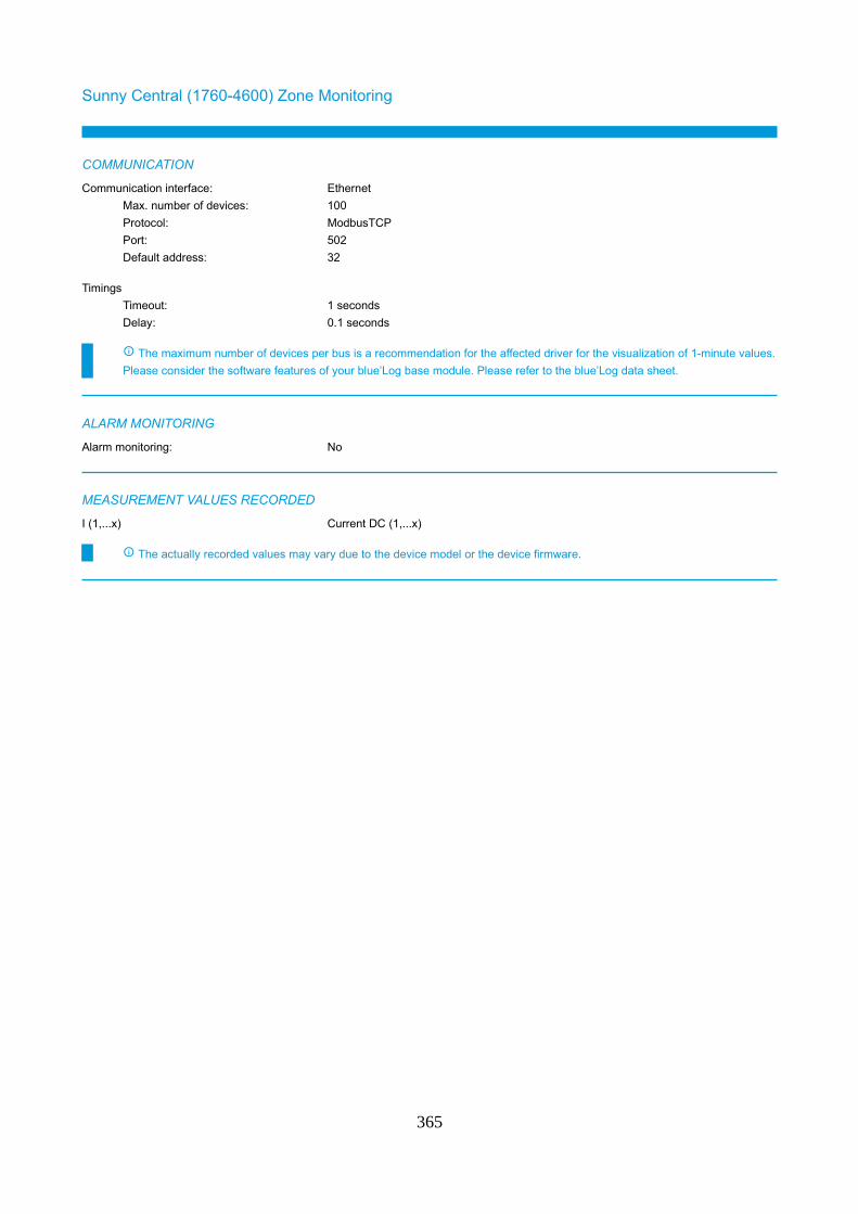
Sunny Central (1760-4600) Zone Monitoring
COMMUNICATION
Communication interface: Ethernet
Max. number of devices: 100
Protocol: ModbusTCP
Port: 502
Default address: 32
Timings
Timeout: 1 seconds
Delay: 0.1 seconds
The maximum number of devices per bus is a recommendation for the affected driver for the visualization of 1-minute values.
Please consider the software features of your blue’Log base module. Please refer to the blue’Log data sheet.
ALARM MONITORING
Alarm monitoring: No
MEASUREMENT VALUES RECORDED
I (1,...x) Current DC (1,...x)
The actually recorded values may vary due to the device model or the device firmware.
365
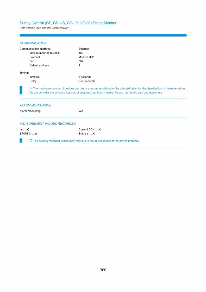
Sunny Central (CP, CP-US, CP-JP, HE-20) String MonitorBeta version (see chapter „Beta version“)
COMMUNICATION
Communication interface: Ethernet
Max. number of devices: 100
Protocol: ModbusTCP
Port: 502
Default address: 4
Timings
Timeout: 5 seconds
Delay: 0.25 seconds
The maximum number of devices per bus is a recommendation for the affected driver for the visualization of 1-minute values.
Please consider the software features of your blue’Log base module. Please refer to the blue’Log data sheet.
ALARM MONITORING
Alarm monitoring: Yes
MEASUREMENT VALUES RECORDED
I (1,...x) Current DC (1,...x)
STATE (1,...x) Status (1,...x)
The actually recorded values may vary due to the device model or the device firmware.
366
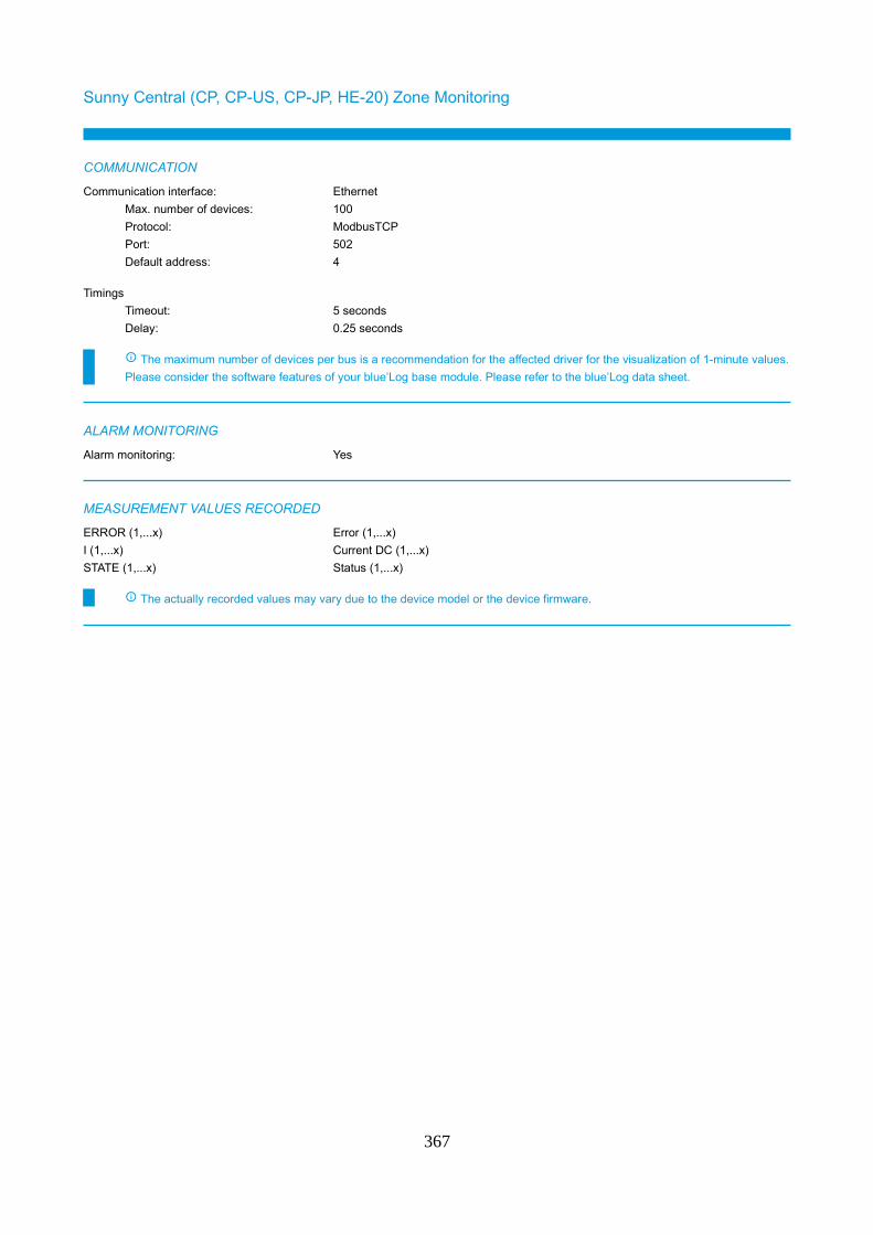
Sunny Central (CP, CP-US, CP-JP, HE-20) Zone Monitoring
COMMUNICATION
Communication interface: Ethernet
Max. number of devices: 100
Protocol: ModbusTCP
Port: 502
Default address: 4
Timings
Timeout: 5 seconds
Delay: 0.25 seconds
The maximum number of devices per bus is a recommendation for the affected driver for the visualization of 1-minute values.
Please consider the software features of your blue’Log base module. Please refer to the blue’Log data sheet.
ALARM MONITORING
Alarm monitoring: Yes
MEASUREMENT VALUES RECORDED
ERROR (1,...x) Error (1,...x)
I (1,...x) Current DC (1,...x)
STATE (1,...x) Status (1,...x)
The actually recorded values may vary due to the device model or the device firmware.
367
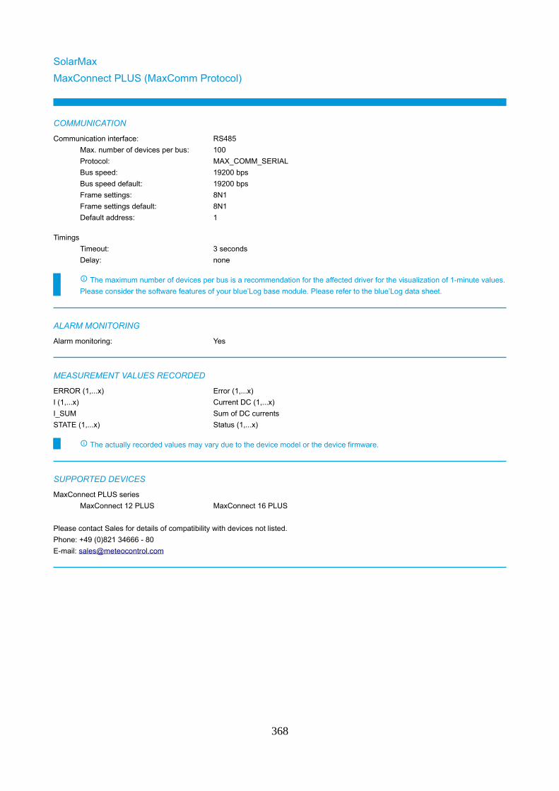
SolarMax
MaxConnect PLUS (MaxComm Protocol)
COMMUNICATION
Communication interface: RS485
Max. number of devices per bus: 100
Protocol: MAX_COMM_SERIAL
Bus speed: 19200 bps
Bus speed default: 19200 bps
Frame settings: 8N1
Frame settings default: 8N1
Default address: 1
Timings
Timeout: 3 seconds
Delay: none
The maximum number of devices per bus is a recommendation for the affected driver for the visualization of 1-minute values.
Please consider the software features of your blue’Log base module. Please refer to the blue’Log data sheet.
ALARM MONITORING
Alarm monitoring: Yes
MEASUREMENT VALUES RECORDED
ERROR (1,...x) Error (1,...x)
I (1,...x) Current DC (1,...x)
I_SUM Sum of DC currents
STATE (1,...x) Status (1,...x)
The actually recorded values may vary due to the device model or the device firmware.
SUPPORTED DEVICES
MaxConnect PLUS series
MaxConnect 12 PLUS MaxConnect 16 PLUS
Please contact Sales for details of compatibility with devices not listed.
Phone: +49 (0)821 34666 - 80
E-mail: [email protected]
368
SunSpec Alliance
Compatible string monitoring
COMMUNICATION
Communication interface: Ethernet
Max. number of devices: 100
Protocol: ModbusTCP
Port: 502
Default address: 1
Communication interface: RS485
Max. number of devices per bus: 100
Protocol: ModbusRTU
Bus speed: 9600 bps, 19200 bps, 38400 bps, 57600 bps, 115200 bps
Bus speed default: 9600 bps
Frame settings: 8N1
Frame settings default: 8N1
Default address: 1
Timings
Timeout: 1 seconds
Delay: none
The maximum number of devices per bus is a recommendation for the affected driver for the visualization of 1-minute values.
Please consider the software features of your blue’Log base module. Please refer to the blue’Log data sheet.
ALARM MONITORING
Alarm monitoring: Yes
MEASUREMENT VALUES RECORDED
Model 401 Model 402 Model 403
Model 404
The actually recorded values may vary due to the device model or the device firmware.
369
TMEIC
SGV
COMMUNICATION
Communication interface: Ethernet
Max. number of devices: 100
Protocol: ModbusTCP
Port: 502
Default address: 1
Timings
Timeout: 1 seconds
Delay: none
The maximum number of devices per bus is a recommendation for the affected driver for the visualization of 1-minute values.
Please consider the software features of your blue’Log base module. Please refer to the blue’Log data sheet.
ALARM MONITORING
Alarm monitoring: Yes
MEASUREMENT VALUES RECORDED
ERROR (1,...x) Error (1,...x)
I (1,...x) Current DC (1,...x)
STATE (1,...x) Status (1,...x)
The actually recorded values may vary due to the device model or the device firmware.
370
Weidmüller
Transclinic xi+
COMMUNICATION
Communication interface: RS485
Max. number of devices per bus: 100
Protocol: ModbusRTU
Bus speed: 9600 bps, 19200 bps
Bus speed default: 19200 bps
Frame settings: 8E1, 8N1
Frame settings default: 8E1
Default address: 1
Timings
Timeout: 1 seconds
Delay: none
The maximum number of devices per bus is a recommendation for the affected driver for the visualization of 1-minute values.
Please consider the software features of your blue’Log base module. Please refer to the blue’Log data sheet.
ALARM MONITORING
Alarm monitoring: No
MEASUREMENT VALUES RECORDED
D_IN (1,...x) Digital input (1,...x)
I (1,...x) Current DC (1,...x)
T Temperature
U_DC Voltage DC
The actually recorded values may vary due to the device model or the device firmware.
SUPPORTED DEVICES
Transclinic 8i+ Transclinic 14i+ Transclinic 16i+
Transclinic 16i+ 1k5 H Transclinic 16i+ 1k5 L
Please contact Sales for details of compatibility with devices not listed.
Phone: +49 (0)821 34666 - 80
E-mail: [email protected]
371
Status DI externalCRD
CRD600A
COMMUNICATION
Communication interface: Ethernet
Max. number of devices: 100
Protocol: ModbusTCP
Port: 502
Default address: 1
Communication interface: RS485
Max. number of devices per bus: 100
Protocol: ModbusRTU
Bus speed: 9600 bps
Bus speed default: 9600 bps
Frame settings: 8N1
Frame settings default: 8N1
Default address: 1
Timings
Timeout: 1 seconds
Delay: none
The maximum number of devices per bus is a recommendation for the affected driver for the visualization of 1-minute values.
Please consider the software features of your blue’Log base module. Please refer to the blue’Log data sheet.
Please note that the CRD600A does not support Modbus TCP by default. Connection via Ethernet just possible by using an
additional RS485/Ethernet converter. Please get in touch with meteocontrol Sales for clarification regarding Ethernet
connection.
ALARM MONITORING
Alarm monitoring: No
MEASUREMENT VALUES RECORDED
D_IN (1,...x) Digital input (1,...x)
The actually recorded values may vary due to the device model or the device firmware.
372
Santerno
Sunway TG Remote I/OBeta version (see chapter „Beta version“)
COMMUNICATION
Communication interface: Ethernet
Max. number of devices: 100
Protocol: ModbusTCP
Port: 502
Default address: 1
Communication interface: RS485
Max. number of devices per bus: 100
Protocol: ModbusRTU
Bus speed: 1200 bps, 2400 bps, 4800 bps, 9600 bps, 19200 bps, 38400 bps, 57600 bps
Bus speed default: 38400 bps
Frame settings: 8N2
Frame settings default: 8N2
Default address: 1
Timings
Timeout: 1 seconds
Delay: none
The maximum number of devices per bus is a recommendation for the affected driver for the visualization of 1-minute values.
Please consider the software features of your blue’Log base module. Please refer to the blue’Log data sheet.
ALARM MONITORING
Alarm monitoring: No
MEASUREMENT VALUES RECORDED
D_IN (1,...x) Digital input (1,...x)
The actually recorded values may vary due to the device model or the device firmware.
373
WAGO
I/O Systems series 750, 750XTR, 753, 767
COMMUNICATION
Communication interface: Ethernet
Max. number of devices: 100
Protocol: ModbusTCP
Port: 502
Default address: 1
Communication interface: RS485
Max. number of devices per bus: 100
Protocol: ModbusRTU
Bus speed: 300 bps, 600 bps, 1200 bps, 2400 bps, 4800 bps, 9600 bps, 19200 bps,
38400 bps, 57600 bps, 115200 bps
Bus speed default: 19200 bps
Frame settings: 8N1, 8E1, 8O1, 8N2, 7N2
Frame settings default: 8N1
Default address: 1
Timings
Timeout: 1 seconds
Delay: none
The maximum number of devices per bus is a recommendation for the affected driver for the visualization of 1-minute values.
Please consider the software features of your blue’Log base module. Please refer to the blue’Log data sheet.
On a 8 channel digital input module the number of the digital input doesn't match to the number of the connection pin. Please
consider this when configuring the device in the blue'Log. Please check the manufacturer manual.
Example:
First module next to the communication module: DI1 = Pin 1, DI2 = Pin 5, DI3 = Pin 2, DI4 = Pin 6, DI5 = Pin 3, DI6 = Pin 7, DI7
= Pin 4, DI8 = Pin 8
Second module next to the communication module: DI9 = Pin 1, DI10 = Pin 5, DI11 = Pin 2, DI12 = Pin 6, DI13 = Pin 3, DI14 =
Pin 7, DI15 = Pin 4, DI16 = Pin 8)
ALARM MONITORING
Alarm monitoring: No
MEASUREMENT VALUES RECORDED
D_IN (1,...x) Digital input (1,...x)
ERROR (1,...x) Error (1,...x)
The actually recorded values may vary due to the device model or the device firmware.
SUPPORTED DEVICES
I/O-System 750 series
I/O-System 750
Speedway 767 series
Speedway 767
374

Please contact Sales for details of compatibility with devices not listed.
Phone: +49 (0)821 34666 - 80
E-mail: [email protected]
375
TrackerArctech Solar
Sky Smart SystemBeta version (see chapter „Beta version“)
COMMUNICATION
Communication interface: RS485
Max. number of devices per bus: 100
Protocol: ModbusRTU
Bus speed: 9600 bps
Bus speed default: 9600 bps
Frame settings: 8N1
Frame settings default: 8N1
Default address: 200
Timings
Timeout: 1 seconds
Delay: none
The maximum number of devices per bus is a recommendation for the affected driver for the visualization of 1-minute values.
Please consider the software features of your blue’Log base module. Please refer to the blue’Log data sheet.
ALARM MONITORING
Alarm monitoring: Yes
MEASUREMENT VALUES RECORDED
AZIMUTH Azimuth
AZIMUTH_TARGET Azimuth, target value
ELEVATION Elevation
ELEVATION_TARGET Elevation, target value
ERROR (1,...x) Error (1,...x)
STATE (1,...x) Status (1,...x)
The actually recorded values may vary due to the device model or the device firmware.
376
Array Technologies
Dura Track HzBeta version (see chapter „Beta version“)
COMMUNICATION
Communication interface: Ethernet
Max. number of devices: 100
Protocol: ModbusTCP
Port: 502
Default address: 1
Timings
Timeout: 1 seconds
Delay: none
The maximum number of devices per bus is a recommendation for the affected driver for the visualization of 1-minute values.
Please consider the software features of your blue’Log base module. Please refer to the blue’Log data sheet.
ALARM MONITORING
Alarm monitoring: Yes
MEASUREMENT VALUES RECORDED
ELEVATION Elevation
ERROR (1,...x) Error (1,...x)
STATE (1,...x) Status (1,...x)
The actually recorded values may vary due to the device model or the device firmware.
377
Ideematec
safe Track TrackersystemBeta version (see chapter „Beta version“)
COMMUNICATION
Communication interface: Ethernet
Max. number of devices: 100
Protocol: ModbusTCP
Port: 502
Default address: 255
Timings
Timeout: 1 seconds
Delay: none
The maximum number of devices per bus is a recommendation for the affected driver for the visualization of 1-minute values.
Please consider the software features of your blue’Log base module. Please refer to the blue’Log data sheet.
One Ideematec Tracker controller consists of up to 120 Tracker and 1 Sensor box (121 devices).
ALARM MONITORING
Alarm monitoring: Yes
MEASUREMENT VALUES RECORDED
ELEVATION Elevation
ELEVATION_TARGET Elevation, target value
ERROR (1,...x) Error (1,...x)
E_W_D1 Wind direction 1
E_W_D2 Wind direction 2
E_W_S1 Wind speed 1
E_W_S2 Wind speed 2
STATE (1,...x) Status (1,...x)
T (1,...x) Temperature (1,...x)
The actually recorded values may vary due to the device model or the device firmware.
378
NCLAVE
Solar tracker SP1000Beta version (see chapter „Beta version“)
COMMUNICATION
Communication interface: Ethernet
Max. number of devices: 100
Protocol: ModbusTCP
Port: 502
Default address: 1
Timings
Timeout: 1 seconds
Delay: none
The maximum number of devices per bus is a recommendation for the affected driver for the visualization of 1-minute values.
Please consider the software features of your blue’Log base module. Please refer to the blue’Log data sheet.
ALARM MONITORING
Alarm monitoring: Yes
MEASUREMENT VALUES RECORDED
ELEVATION Elevation
ERROR (1,...x) Error (1,...x)
E_W_S Wind speed
STATE (1,...x) Status (1,...x)
The actually recorded values may vary due to the device model or the device firmware.
379
NEXTracker
NX HorizonBeta version (see chapter „Beta version“)
COMMUNICATION
Communication interface: Ethernet
Max. number of devices: 100
Protocol: ModbusTCP
Port: 502
Default address: 1
Timings
Timeout: 1 seconds
Delay: none
The maximum number of devices per bus is a recommendation for the affected driver for the visualization of 1-minute values.
Please consider the software features of your blue’Log base module. Please refer to the blue’Log data sheet.
It is possible to connect a combination of up to 100 SPCs (Self-Powered Controller) and Weather Stations to a single NCU
(Network Control Unit).
Depending on the amount of SPCs and Weather Stations connected to the NCU the total amount of devices varies that can be
connected to one blue’Log (e.g. 99 SPCs + 1 Weather Station = 100 devices).
ALARM MONITORING
Alarm monitoring: Yes
MEASUREMENT VALUES RECORDED
ELEVATION Elevation
ELEVATION_TARGET Elevation, target value
ERROR (1,...x) Error (1,...x)
E_SNOW_DEPTH Snow depth
E_W_S Wind speed
STATE (1,...x) Status (1,...x)
T (1,...x) Temperature (1,...x)
The actually recorded values may vary due to the device model or the device firmware.
380
Soltec
SF Tracker
COMMUNICATION
Communication interface: Ethernet
Max. number of devices: 100
Protocol: ModbusTCP
Port: 502
Default address: 1
Timings
Timeout: 1 seconds
Delay: none
The maximum number of devices per bus is a recommendation for the affected driver for the visualization of 1-minute values.
Please consider the software features of your blue’Log base module. Please refer to the blue’Log data sheet.
For a successful scan the angle of the trackers must not be zero degrees. If the angle will be zero degrees the scan will fail.
ALARM MONITORING
Alarm monitoring: Yes
MEASUREMENT VALUES RECORDED
ELEVATION Elevation
ELEVATION_TARGET Elevation, target value
ERROR (1,...x) Error (1,...x)
STATE (1,...x) Status (1,...x)
The actually recorded values may vary due to the device model or the device firmware.
381
SunTrack
SunTrackBeta version (see chapter „Beta version“)
COMMUNICATION
Communication interface: Ethernet
Max. number of devices: 100
Protocol: ModbusTCP
Port: 502
Default address: 1
Timings
Timeout: 1 seconds
Delay: none
The maximum number of devices per bus is a recommendation for the affected driver for the visualization of 1-minute values.
Please consider the software features of your blue’Log base module. Please refer to the blue’Log data sheet.
ALARM MONITORING
Alarm monitoring: Yes
MEASUREMENT VALUES RECORDED
ELEVATION Elevation
ELEVATION_TARGET Elevation, target value
ERROR (1,...x) Error (1,...x)
E_SNOW_DEPTH Snow depth
E_W_S Wind speed
SRAD Irradiance
STATE (1,...x) Status (1,...x)
T (1,...x) Temperature (1,...x)
The actually recorded values may vary due to the device model or the device firmware.
382
BatteryADS-TEC
StoraXe Master
COMMUNICATION
Communication interface: Ethernet
Max. number of devices: 100
Protocol: ModbusTCP
Port: 502
Default address: 1
Timings
Timeout: 1 seconds
Delay: none
The maximum number of devices per bus is a recommendation for the affected driver for the visualization of 1-minute values.
Please consider the software features of your blue’Log base module. Please refer to the blue’Log data sheet.
ALARM MONITORING
Alarm monitoring: Yes
MEASUREMENT VALUES RECORDED
B_CHARGE_LEVEL Charging status
B_E_EXP Energy from storage system
B_E_IMP Energy to storage system
B_I_DC Battery current
B_P_DC Battery power
B_U_DC Battery voltage
ERROR (1,...x) Error (1,...x)
STATE (1,...x) Status (1,...x)
T (1,...x) Temperature (1,...x)
The actually recorded values may vary due to the device model or the device firmware.
383
DEIF
ASC Genset (with AGC)
COMMUNICATION
Communication interface: Ethernet
Max. number of devices: 100
Protocol: ModbusTCP
Port: 502
Default address: 1
Timings
Timeout: 1 seconds
Delay: 0.02 seconds
The maximum number of devices per bus is a recommendation for the affected driver for the visualization of 1-minute values.
Please consider the software features of your blue’Log base module. Please refer to the blue’Log data sheet.
Depending on the amount of gensets connected to the DEIF Controller the total amount of devices varies that can be
connected to one blue’Log (e.g. 1 x DEIF ASC = up to 16 devices).
The gensets must be equipped with DEIF AGC controllers connected to the ASC on the DEIF internal Power Management
communication line.
ALARM MONITORING
Alarm monitoring: Yes
MEASUREMENT VALUES RECORDED
ERROR (1,...x) Error (1,...x)
FUEL_CONSUMPTION Fuel consumption
FUEL_EFFICIENCY Fuel efficiency
FUEL_REMAINING Fuel remaining
OT_TOTAL Operation hours
P_AC Power AC
P_AC_SET_ABS Absolute active power setpoint
P_AC_SET_REL Relative active power setpoint
Q_AC Reactive power
Q_AC_SET_ABS Absolute reactive power setpoint
The actually recorded values may vary due to the device model or the device firmware.
384
ASC Genset (without AGC)Beta version (see chapter „Beta version“)
COMMUNICATION
Communication interface: Ethernet
Max. number of devices: 100
Protocol: ModbusTCP
Port: 502
Default address: 1
Timings
Timeout: 1 seconds
Delay: 0.02 seconds
The maximum number of devices per bus is a recommendation for the affected driver for the visualization of 1-minute values.
Please consider the software features of your blue’Log base module. Please refer to the blue’Log data sheet.
Depending on the amount of gensets connected to the DEIF Controller the total amount of devices varies that can be
connected to one blue’Log (e.g. 1 x DEIF ASC = up to 16 devices).
If the ASC receives data not from the DEIF AGC controllers but from meters connected to the ASC then it's necessary to use
this driver.
ALARM MONITORING
Alarm monitoring: No
MEASUREMENT VALUES RECORDED
D_IN (1,...x) Digital input (1,...x)
P_AC Power AC
P_AC_SET_ABS Absolute active power setpoint
P_AC_SET_REL Relative active power setpoint
Q_AC Reactive power
Q_AC_SET_ABS Absolute reactive power setpoint
The actually recorded values may vary due to the device model or the device firmware.
385
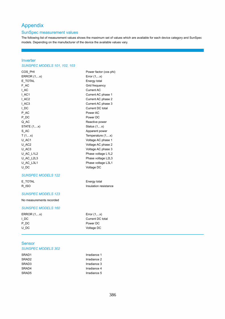
AppendixSunSpec measurement valuesThe following list of measurement values shows the maximum set of values which are available for each device category and SunSpec
models. Depending on the manufacturer of the device the available values vary.
InverterSUNSPEC MODELS 101, 102, 103
COS_PHI Power factor (cos phi)
ERROR (1,...x) Error (1,...x)
E_TOTAL Energy total
F_AC Grid frequency
I_AC Current AC
I_AC1 Current AC phase 1
I_AC2 Current AC phase 2
I_AC3 Current AC phase 3
I_DC Current DC total
P_AC Power AC
P_DC Power DC
Q_AC Reactive power
STATE (1,...x) Status (1,...x)
S_AC Apparent power
T (1,...x) Temperature (1,...x)
U_AC1 Voltage AC phase 1
U_AC2 Voltage AC phase 2
U_AC3 Voltage AC phase 3
U_AC_L1L2 Phase voltage L1L2
U_AC_L2L3 Phase voltage L2L3
U_AC_L3L1 Phase voltage L3L1
U_DC Voltage DC
SUNSPEC MODELS 122
E_TOTAL Energy total
R_ISO Insulation resistance
SUNSPEC MODELS 123
No measurements recorded
SUNSPEC MODELS 160
ERROR (1,...x) Error (1,...x)
I_DC Current DC total
P_DC Power DC
U_DC Voltage DC
SensorSUNSPEC MODELS 302
SRAD1 Irradiance 1
SRAD2 Irradiance 2
SRAD3 Irradiance 3
SRAD4 Irradiance 4
SRAD5 Irradiance 5
386
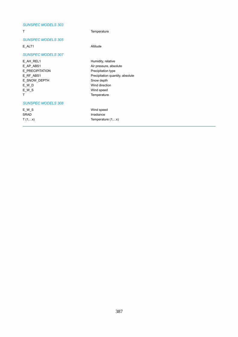
SUNSPEC MODELS 303
T Temperature
SUNSPEC MODELS 305
E_ALT1 Altitude
SUNSPEC MODELS 307
E_AH_REL1 Humidity, relative
E_AP_ABS1 Air pressure, absolute
E_PRECIPITATION Precipitation type
E_RF_ABS1 Precipitation quantity, absolute
E_SNOW_DEPTH Snow depth
E_W_D Wind direction
E_W_S Wind speed
T Temperature
SUNSPEC MODELS 308
E_W_S Wind speed
SRAD Irradiance
T (1,...x) Temperature (1,...x)
387
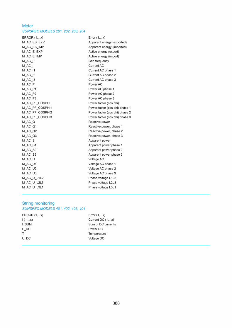
MeterSUNSPEC MODELS 201, 202, 203, 204
ERROR (1,...x) Error (1,...x)
M_AC_ES_EXP Apparent energy (exported)
M_AC_ES_IMP Apparent energy (imported)
M_AC_E_EXP Active energy (export)
M_AC_E_IMP Active energy (import)
M_AC_F Grid frequency
M_AC_I Current AC
M_AC_I1 Current AC phase 1
M_AC_I2 Current AC phase 2
M_AC_I3 Current AC phase 3
M_AC_P Power AC
M_AC_P1 Power AC phase 1
M_AC_P2 Power AC phase 2
M_AC_P3 Power AC phase 3
M_AC_PF_COSPHI Power factor (cos phi)
M_AC_PF_COSPHI1 Power factor (cos phi) phase 1
M_AC_PF_COSPHI2 Power factor (cos phi) phase 2
M_AC_PF_COSPHI3 Power factor (cos phi) phase 3
M_AC_Q Reactive power
M_AC_Q1 Reactive power, phase 1
M_AC_Q2 Reactive power, phase 2
M_AC_Q3 Reactive power, phase 3
M_AC_S Apparent power
M_AC_S1 Apparent power phase 1
M_AC_S2 Apparent power phase 2
M_AC_S3 Apparent power phase 3
M_AC_U Voltage AC
M_AC_U1 Voltage AC phase 1
M_AC_U2 Voltage AC phase 2
M_AC_U3 Voltage AC phase 3
M_AC_U_L1L2 Phase voltage L1L2
M_AC_U_L2L3 Phase voltage L2L3
M_AC_U_L3L1 Phase voltage L3L1
String monitoringSUNSPEC MODELS 401, 402, 403, 404
ERROR (1,...x) Error (1,...x)
I (1,...x) Current DC (1,...x)
I_SUM Sum of DC currents
P_DC Power DC
T Temperature
U_DC Voltage DC
388