rs232 interface with flow-bus protocol for digital multibus mass flow / pressure ... · for digital...
TRANSCRIPT
Instruction manual
RS232 interface with FLOW-BUS protocol
for digital multibus Mass Flow / Pressure instruments
Doc. no.: 9.17.027AB Date: 20-09-2017
ATTENTION Please read this instruction manual carefully before installing and operating the instrument. Not following the guidelines could result in personal injury and/or damage to the equipment.

BRONKHORST®
Page 2 RS232 interface 9.17.027
Disclaimer The information in this manual has been reviewed and is believed to be wholly reliable. No responsibility, however, is assumed for inaccuracies. The material in this manual is for information purposes only.
Copyright All rights reserved. This documentation is protected by copyright. Subject to technical and optical changes as well as printing errors. The information contained in this document is subject to change at any time without prior notification. Bronkhorst High-Tech B.V. reserves the right to modify or improve its products and modify the contents without being obliged to inform any particular persons or organizations. The device specifications and the contents of the package may deviate from what is stated in this document.
Symbols
Important information. Discarding this information could cause injuries to people or damage to the Instrument or installation.
Helpful information. This information will facilitate the use of this instrument.
Additional info available on the internet or from your local sales representative.
Warranty Bronkhorst® products are warranted against defects in material and workmanship for a period of three years from the date of shipment, provided they are used in accordance with the ordering specifications and the instructions in this manual and that they are not subjected to abuse, physical damage or contamination. Products that do not operate properly during this period may be repaired or replaced at no charge. Repairs are normally warranted for one year or the balance of the original warranty, whichever is the longer.
See also paragraph 9 of the Conditions of sales: http://www.bronkhorst.com/files/corporate_headquarters/sales_conditions/en_general_terms_of_sales.pdf
The warranty includes all initial and latent defects, random failures, and undeterminable internal causes. It excludes failures and damage caused by the customer, such as contamination, improper electrical hook-up, physical shock etc. Re-conditioning of products primarily returned for warranty service that is partly or wholly judged non-warranty may be charged for. Bronkhorst High-Tech B.V. or affiliated company prepays outgoing freight charges when any party of the service is performed under warranty, unless otherwise agreed upon beforehand. However, if the product has been returned collect to our factory or service center, these costs are added to the repair invoice. Import and/or export charges, foreign shipping methods/carriers are paid for by the customer.

BRONKHORST®
Page 3 RS232 interface 9.17.027
Table of contents
1 GENERAL PRODUCT INFORMATION ................................................................................................. 5 1.1 INTRODUCTION ................................................................................................................................................ 5 1.2 MULTIBUS TYPES .............................................................................................................................................. 5 1.3 REFERENCES TO OTHER APPLICABLE DOCUMENTS ..................................................................................................... 6
1.3.1 Manuals and user guides: ........................................................................................................................... 6 1.3.2 Technical Drawings: .................................................................................................................................... 6 1.3.3 Software tooling: ........................................................................................................................................ 6
1.4 SHORT FORM START-UP ..................................................................................................................................... 7 2 INTERFACES..................................................................................................................................... 8
2.1 RS232/FLOW-BUS INTERFACE ......................................................................................................................... 8 2.1.1 D-connector for RS232 ................................................................................................................................ 8
2.2 RS232 ON MULTIBUS INSTRUMENT ...................................................................................................................... 9 2.2.1 Applications, e.g. EL-FLOW ......................................................................................................................... 9 2.2.2 Facilities .................................................................................................................................................... 10 2.2.3 Baudrates multibus RS232: ....................................................................................................................... 10
3 FLOW-BUS PROTOCOL DESCRIPTION .............................................................................................. 11 3.1 GENERAL .......................................................................................................................................................11 3.2 INITIALISATION OF LOCAL HOST INTERFACES ON MULTIBUS INSTRUMENTS ....................................................................11 3.3 INTERFACE STRUCTURE .....................................................................................................................................12
3.3.1 Basic datalink format ................................................................................................................................ 12 3.3.2 ASCII table ................................................................................................................................................. 12 3.3.3 RS232 ASCII protocol ................................................................................................................................. 13
3.4 COMMUNICATION MESSAGES .............................................................................................................................15 3.4.1 Communication commands ...................................................................................................................... 15 3.4.2 Parameter types ........................................................................................................................................ 16
3.5 CHAINING ......................................................................................................................................................16 3.6 STATUS MESSAGE ............................................................................................................................................17 3.7 SEND PARAMETERS ..........................................................................................................................................18 3.8 REQUEST PARAMETER ......................................................................................................................................18 3.9 EXAMPLES – RS232 ASCII PROTOCOL .................................................................................................................20
3.9.1 Sending setpoint ....................................................................................................................................... 20 3.9.2 Request setpoint ....................................................................................................................................... 21 3.9.3 Request measure....................................................................................................................................... 22 3.9.4 Request counter value............................................................................................................................... 23 3.9.5 Collection of RS232 ASCII examples .......................................................................................................... 24 3.9.6 Request chained parameters .................................................................................................................... 33 3.9.7 Example Request chained parameters, setpoint and measure ................................................................. 35 3.9.8 Example Request chained parameters, measure and temperature .......................................................... 35 3.9.9 Example Request chained parameters, fmeasure and temperature ........................................................ 35
3.10 EXAMPLES - RS232 ENHANCED BINARY PROTOCOL .................................................................................................36 3.10.1 Sending setpoint - RS232 Enhanced binary protocol................................................................................. 36 3.10.2 Request setpoint - RS232 enhanced binary protocol ................................................................................ 37 3.10.3 Request measure - RS232 enhanced binary protocol ................................................................................ 38 3.10.4 Collection of RS232 enhanced binary examples ........................................................................................ 39 3.10.5 Example chained parameters - RS232 enhanced binary protocol ............................................................. 40
4 DUAL INTERFACE OPERATION ........................................................................................................ 41
5 PARAMETER INFORMATION .......................................................................................................... 42
6 TROUBLESHOOTING ...................................................................................................................... 44 6.1 LED INDICATIONS ............................................................................................................................................44 6.2 TROUBLESHOOTING HINTS AND TIPS ....................................................................................................................44
BRONKHORST®
Page 4 RS232 interface 9.17.027
7 SERVICE ........................................................................................................................................ 45
8 APPENDIX ..................................................................................................................................... 46 8.1 PARAMETER VALUES TABLE ................................................................................................................................46 8.2 PARAMETER PROPERTIES TABLE ..........................................................................................................................46

BRONKHORST®
Page 5 RS232 interface 9.17.027
1 GENERAL PRODUCT INFORMATION 1.1 INTRODUCTION This manual will explain how to communicate with a Bronkhorst® instrument to your PC/PLC using RS232 serial communication. You have to write software yourself using the information of this document in order to be able to operate these instruments. Bronkhorst® also offers software to easily operate digital instruments with your PC using Microsoft Windows. On the highest supported communication level, you may use FlowDDE channels for Windows application-programs with this facility. You can use the program FlowDDE for easy connection between Windows applications (e.g. Excel, Visual Basic, LabVIEW, Delphi, Borland C) and digital instruments. There are several examples available for LabVIEW, Visual Basic and Excel environments. On a lower communication level, you can also use the FLOWB32.DLL for reading/changing parameter values. To read and write parameter values from or to FLOW-BUS devices directly through the available interfaces there is a special protocol for messages between these devices. This protocol has been specially developed for Bronkhorst® equipment so no third party equipment can be connected. It consists of a hierarchical setup for instruments / nodes (max. 126) containing processes (max. 127) with parameters (FBnr) (max. 32) which values can be set to certain values to enable settings/properties for the instruments. When operating a FLOW-BUS system with a HOST computer, you need to know this message protocol if you choose to drive the interfaces directly. When you communicate directly via RS232 on a Multibus instrument or when you use a RS232/FLOW-BUS (baud rates up to 38K4 with switch and 2 LED’s) interface, no special initialisation is needed.
1.2 MULTIBUS TYPES In 2000 Bronkhorst® developed their first digital instruments according to the “multibus” principle. The basic pc-board on the instrument contained all of the general functions needed for measurement and control, including alarm, totalizing and diagnostic functions. It had analog I/O-signals and also an RS232 connection as a standard feature. In addition to this there is the possibility of integrating an interface board with DeviceNet™, PROFIBUS DP, Modbus , FLOW-BUS or EtherCAT protocol. The first generation (MBC-I) was based on a 16 bit Fujitsu controller. It was superseded in 2003 by the Multibus type 2 (MBC-II). This version was also based on the 16 bit Fujitsu controller but it had several improvements to the MBC-I. One of them is the current steering of the valve. It reduced heat production and improved control characteristics. The latest version Multibus controller type 3 (MBC3) is introduced in 2011. It is built around a 72MHz 32 bit NXP ARM controller. It has AD and DA controllers on board which makes it possible to measure noise free and control valves without delays. The internal control loop runs 6 times faster compared to the MBC-II therefore control stability has improved significantly. It also has several improved functions like reverse voltage protection, inrush current limitation and overvoltage protection. MBC3 instruments can be recognised by the “MBC3” placed on lower left side of the instrument label (see example).
BRONKHORST®
Page 6 RS232 interface 9.17.027
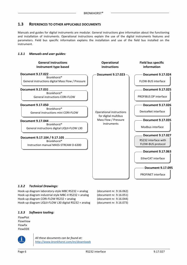
1.3 REFERENCES TO OTHER APPLICABLE DOCUMENTS Manuals and guides for digital instruments are modular. General instructions give information about the functioning and installation of instruments. Operational instructions explain the use of the digital instruments features and parameters. Field bus specific information explains the installation and use of the field bus installed on the instrument.
1.3.1 Manuals and user guides:
1.3.2 Technical Drawings: Hook-up diagram laboratory-style MBC RS232 + analog (document nr. 9.16.062) Hook-up diagram industrial style MBC-II RS232 + analog (document nr. 9.16.051) Hook-up diagram CORI-FLOW RS232 + analog (document nr. 9.16.044) Hook-up diagram LIQUI-FLOW L30 digital RS232 + analog (document nr. 9.16.073)
1.3.3 Software tooling: FlowPlot FlowView Flowfix FlowDDE
All these documents can be found at: http://www.bronkhorst.com/en/downloads
RS232 interface with FLOW-BUS protocol
Modbus interface
DeviceNet interface
PROFIBUS DP interface
FLOW-BUS interface
Operational instructions for digital multibus
Mass Flow / Pressure instruments
Bronkhorst® General instructions digital Mass Flow / Pressure
Bronkhorst® General instructions CORI-FLOW
Bronkhorst® General instructions mini CORI-FLOW
Bronkhorst® General instructions digital LIQUI-FLOW L30
Document 9.17.022
Document 9.17.050
Document 9.17.044
Document 9.17.023 Document 9.17.024
Document 9.17.025
Document 9.17.026
Document 9.17.035
Document 9.17.027
General instructions Instrument type based
Operational instructions
Field bus specific information
Document 9.17.031
Bronkhorst® Instruction manual MASS-STREAM D-6300
EtherCAT interface
Document 9.17.063
PROFINET interface
Document 9.17.095
Document 9.17.104 / 9.17.105
BRONKHORST®
Page 7 RS232 interface 9.17.027
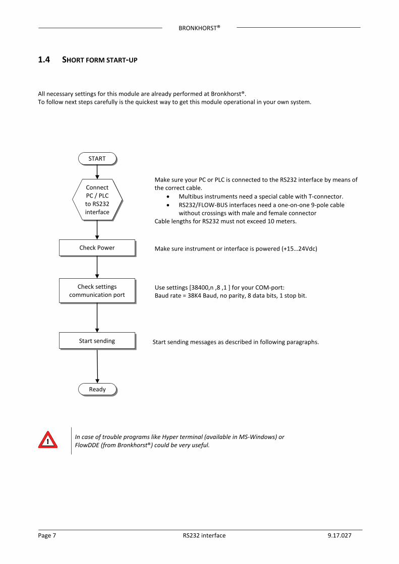
1.4 SHORT FORM START-UP All necessary settings for this module are already performed at Bronkhorst®. To follow next steps carefully is the quickest way to get this module operational in your own system.
In case of trouble programs like Hyper terminal (available in MS-Windows) or FlowDDE (from Bronkhorst®) could be very useful.
START
Connect PC / PLC to RS232 interface
Check Power
Make sure your PC or PLC is connected to the RS232 interface by means of the correct cable.
• Multibus instruments need a special cable with T-connector. • RS232/FLOW-BUS interfaces need a one-on-one 9-pole cable
without crossings with male and female connector Cable lengths for RS232 must not exceed 10 meters.
Make sure instrument or interface is powered (+15…24Vdc)
Check settings communication port
Use settings [38400,n ,8 ,1 ] for your COM-port: Baud rate = 38K4 Baud, no parity, 8 data bits, 1 stop bit.
Ready
Start sending messages as described in following paragraphs. Start sending
BRONKHORST®
Page 8 RS232 interface 9.17.027
2 INTERFACES
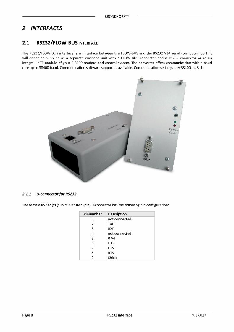
2.1 RS232/FLOW-BUS INTERFACE The RS232/FLOW-BUS interface is an interface between the FLOW-BUS and the RS232 V24 serial (computer) port. It will either be supplied as a separate enclosed unit with a FLOW-BUS connector and a RS232 connector or as an integral 14TE module of your E-8000 readout and control system. The converter offers communication with a baud rate up to 38400 baud. Communication software support is available. Communication settings are: 38400, n, 8, 1.
2.1.1 D-connector for RS232 The female RS232 (x) (sub miniature 9-pin) D-connector has the following pin configuration:
Pinnumber Description 1 2 3 4 5 6 7 8 9
not connected TXD RXD not connected 0 Vd DTR CTS RTS Shield
BRONKHORST®
Page 9 RS232 interface 9.17.027
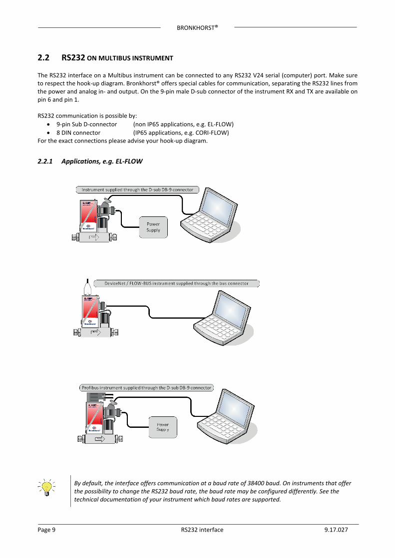
2.2 RS232 ON MULTIBUS INSTRUMENT The RS232 interface on a Multibus instrument can be connected to any RS232 V24 serial (computer) port. Make sure to respect the hook-up diagram. Bronkhorst® offers special cables for communication, separating the RS232 lines from the power and analog in- and output. On the 9-pin male D-sub connector of the instrument RX and TX are available on pin 6 and pin 1. RS232 communication is possible by:
• 9-pin Sub D-connector (non IP65 applications, e.g. EL-FLOW) • 8 DIN connector (IP65 applications, e.g. CORI-FLOW)
For the exact connections please advise your hook-up diagram.
2.2.1 Applications, e.g. EL-FLOW
By default, the interface offers communication at a baud rate of 38400 baud. On instruments that offer the possibility to change the RS232 baud rate, the baud rate may be configured differently. See the technical documentation of your instrument which baud rates are supported.
BRONKHORST®
Page 10 RS232 interface 9.17.027
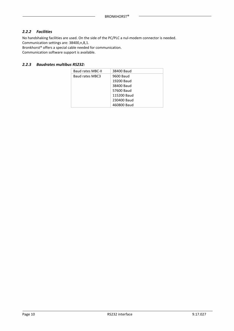
2.2.2 Facilities No handshaking facilities are used. On the side of the PC/PLC a nul-modem connector is needed. Communication settings are: 38400,n,8,1. Bronkhorst® offers a special cable needed for communication. Communication software support is available.
2.2.3 Baudrates multibus RS232: Baud rates MBC-II 38400 Baud Baud rates MBC3 9600 Baud
19200 Baud 38400 Baud 57600 Baud 115200 Baud 230400 Baud 460800 Baud

BRONKHORST®
Page 11 RS232 interface 9.17.027
3 FLOW-BUS PROTOCOL DESCRIPTION 3.1 GENERAL On the highest supported communication level, you may use DDE-channels for Windows application-programs with this facility. On a lower communication level, you can use the FLOWB32.DLL, for changing parameter values. To read and write parameter values from or to FLOW-BUS devices directly through the available interfaces there is a special protocol for messages between these devices. When operating a FLOW-BUS system with a HOST computer, you need to know this message protocol if you choose to drive the interfaces directly. There are two different communication protocols for the PC and the RS232 HOST:
• an ASCII protocol for communication that is compatible with existing FLOW-BUS applications. This protocol serves only one master/slave dialog at a time.
• an enhanced binary protocol that supports concurrent sending of messages to different nodes. This protocol
contains a message-sequence number and serves more than one master/slave dialogs at a time. The RS232-HOST module automatically recognises the protocol used by the PC and adapts its behaviour to the protocol in use. The type of protocol is determined by the first character of a message.
• The first character is ‘:’ (0x3A) existing type of message. • The first character is DLE (0x10) enhanced type of message.
Via the FLOW-BUS DLL (FLOWB32.DLL) the PC determines which protocol is in use. The communication relation is always master (PC) and slave (HOST). The HOST will always respond on a request from the PC.
3.2 INITIALISATION OF LOCAL HOST INTERFACES ON MULTIBUS INSTRUMENTS When you use a digital instrument with RS232 interface, baud rate is fixed on 38K4 baud and no special initialisation is needed. Through the serial line connected to a COM-port of your computer or to a PLC you have to communicate with the instrument using the FLOW-BUS protocol. Each instrument has its own node address (3...120). If you want to send a message to the instrument you have to know this node address. However, if you send a message to node address 128 the instrument will always respond to your message. On a point-to-point connection like RS232 it is the easiest way to make the communication work under all circumstances (it is independent of the real node address of the instrument).

BRONKHORST®
Page 12 RS232 interface 9.17.027
3.3 INTERFACE STRUCTURE
3.3.1 Basic datalink format The basic data link message format has the following fields:
node message destination length data field length data data Data etc.
In the FLOW-BUS environment the data field may contain up to 256 bytes of data. In the HOST application described here, the messages are according to PROPAR coding rules and the data field will contain a maximum of 64 bytes.
3.3.2 ASCII table The American Standard Code for Information Interchange (ASCII) is a character-encoding scheme based on the ordering of the English alphabet. ASCII codes represent text in computers, communications equipment, and other devices that use text. Most modern character-encoding schemes are based on ASCII. Dec Oct Hex Binary Code Dec Oct Hex Binary Code Dec Oct Hex Binary Code Dec Oct Hex Binary Code 32 040 20 0100000 SP 56 070 38 0111000 8 80 120 50 1010000 P 104 150 68 1101000 h 33 041 21 0100001 ! 57 071 39 0111001 9 81 121 51 1010001 Q 105 151 69 1101001 i 34 042 22 0100010 " 58 072 3A 0111010 : 82 122 52 1010010 R 106 152 6A 1101010 j 35 043 23 0100011 # 59 073 3B 0111011 ; 83 123 53 1010011 S 107 153 6B 1101011 k 36 044 24 0100100 $ 60 074 3C 0111100 < 84 124 54 1010100 T 108 154 6C 1101100 l 37 045 25 0100101 % 61 075 3D 0111101 = 85 125 55 1010101 U 109 155 6D 1101101 m 38 046 26 0100110 & 62 076 3E 0111110 > 86 126 56 1010110 V 110 156 6E 1101110 n 39 047 27 0100111 ' 63 077 3F 0111111 ? 87 127 57 1010111 W 111 157 6F 1101111 o 40 050 28 0101000 ( 64 100 40 1000000 @ 88 130 58 1011000 X 112 160 70 1110000 p 41 051 29 0101001 ) 65 101 41 1000001 A 89 131 59 1011001 Y 113 161 71 1110001 q 42 052 2A 0101010 * 66 102 42 1000010 B 90 132 5A 1011010 Z 114 162 72 1110010 r 43 053 2B 0101011 + 67 103 43 1000011 C 91 133 5B 1011011 [ 115 163 73 1110011 s 44 054 2C 0101100 , 68 104 44 1000100 D 92 134 5C 1011100 \ 116 164 74 1110100 t 45 055 2D 0101101 - 69 105 45 1000101 E 93 135 5D 1011101 ] 117 165 75 1110101 u 46 056 2E 0101110 . 70 106 46 1000110 F 94 136 5E 1011110 ^ 118 166 76 1110110 v 47 057 2F 0101111 / 71 107 47 1000111 G 95 137 5F 1011111 _ 119 167 77 1110111 w 48 060 30 0110000 0 72 110 48 1001000 H 96 140 60 1100000 ` 120 170 78 1111000 x 49 061 31 0110001 1 73 111 49 1001001 I 97 141 61 1100001 a 121 171 79 1111001 y 50 062 32 0110010 2 74 112 4A 1001010 J 98 142 62 1100010 b 122 172 7A 1111010 z 51 063 33 0110011 3 75 113 4B 1001011 K 99 143 63 1100011 c 123 173 7B 1111011 { 52 064 34 0110100 4 76 114 4C 1001100 L 100 144 64 1100100 d 124 174 7C 1111100 | 53 065 35 0110101 5 77 115 4D 1001101 M 101 145 65 1100101 e 125 175 7D 1111101 } 54 066 36 0110110 6 78 116 4E 1001110 N 102 146 66 1100110 f 126 176 7E 1111110 ~ 55 067 37 0110111 7 79 117 4F 1001111 O 103 147 67 1100111 g 127 177 7F 1111111 DEL
BRONKHORST®
Page 13 RS232 interface 9.17.027
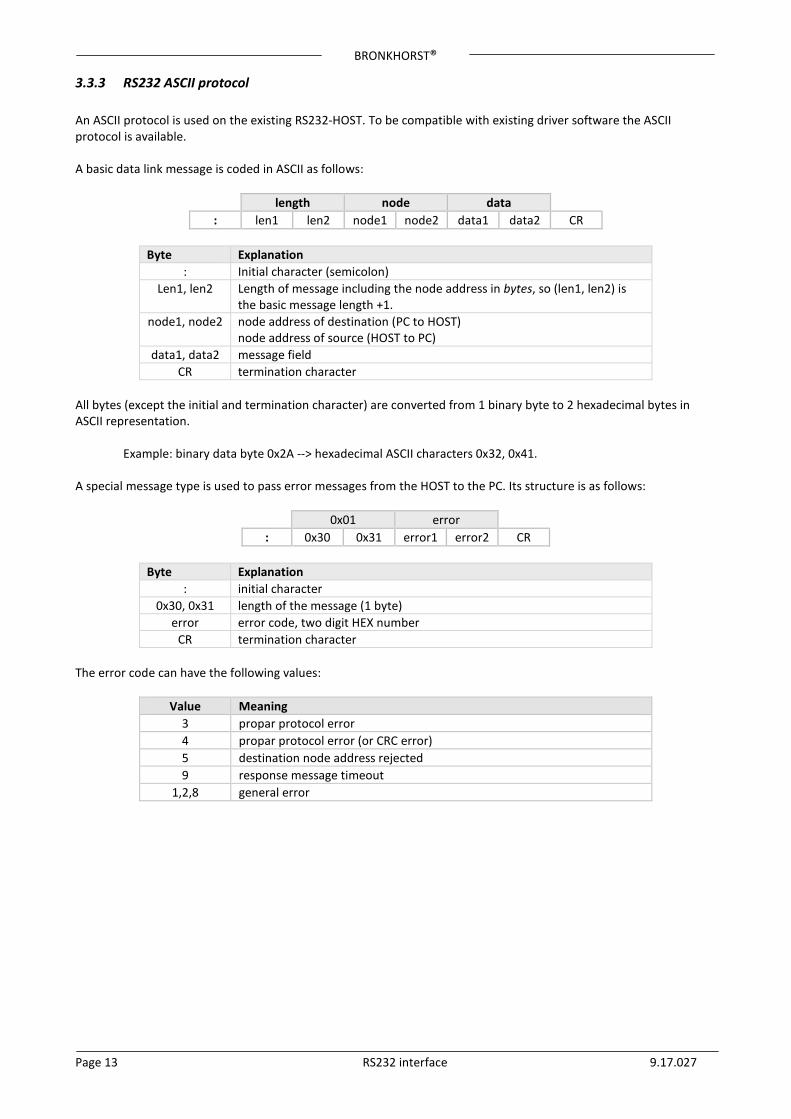
3.3.3 RS232 ASCII protocol An ASCII protocol is used on the existing RS232-HOST. To be compatible with existing driver software the ASCII protocol is available. A basic data link message is coded in ASCII as follows:
length node data : len1 len2 node1 node2 data1 data2 CR
Byte Explanation
: Initial character (semicolon) Len1, len2 Length of message including the node address in bytes, so (len1, len2) is
the basic message length +1. node1, node2 node address of destination (PC to HOST)
node address of source (HOST to PC) data1, data2 message field
CR termination character All bytes (except the initial and termination character) are converted from 1 binary byte to 2 hexadecimal bytes in ASCII representation.
Example: binary data byte 0x2A --> hexadecimal ASCII characters 0x32, 0x41. A special message type is used to pass error messages from the HOST to the PC. Its structure is as follows:
0x01 error : 0x30 0x31 error1 error2 CR
Byte Explanation
: initial character 0x30, 0x31 length of the message (1 byte)
error error code, two digit HEX number CR termination character
The error code can have the following values:
Value Meaning 3 propar protocol error 4 propar protocol error (or CRC error) 5 destination node address rejected 9 response message timeout
1,2,8 general error
BRONKHORST®
Page 14 RS232 interface 9.17.027
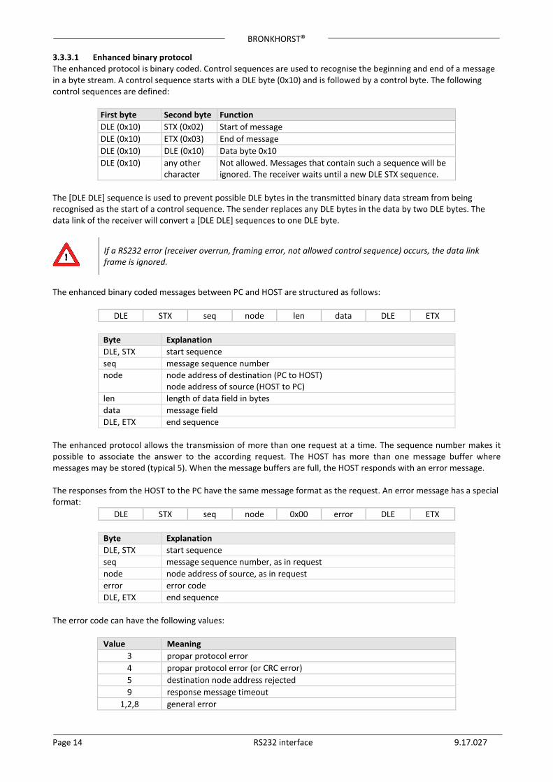
3.3.3.1 Enhanced binary protocol The enhanced protocol is binary coded. Control sequences are used to recognise the beginning and end of a message in a byte stream. A control sequence starts with a DLE byte (0x10) and is followed by a control byte. The following control sequences are defined:
First byte Second byte Function DLE (0x10) STX (0x02) Start of message DLE (0x10) ETX (0x03) End of message DLE (0x10) DLE (0x10) Data byte 0x10 DLE (0x10) any other
character Not allowed. Messages that contain such a sequence will be ignored. The receiver waits until a new DLE STX sequence.
The [DLE DLE] sequence is used to prevent possible DLE bytes in the transmitted binary data stream from being recognised as the start of a control sequence. The sender replaces any DLE bytes in the data by two DLE bytes. The data link of the receiver will convert a [DLE DLE] sequences to one DLE byte.
If a RS232 error (receiver overrun, framing error, not allowed control sequence) occurs, the data link frame is ignored.
The enhanced binary coded messages between PC and HOST are structured as follows:
DLE STX seq node len data DLE ETX
Byte Explanation DLE, STX start sequence seq message sequence number node node address of destination (PC to HOST)
node address of source (HOST to PC) len length of data field in bytes data message field DLE, ETX end sequence
The enhanced protocol allows the transmission of more than one request at a time. The sequence number makes it possible to associate the answer to the according request. The HOST has more than one message buffer where messages may be stored (typical 5). When the message buffers are full, the HOST responds with an error message. The responses from the HOST to the PC have the same message format as the request. An error message has a special format:
DLE STX seq node 0x00 error DLE ETX
Byte Explanation DLE, STX start sequence seq message sequence number, as in request node node address of source, as in request error error code DLE, ETX end sequence
The error code can have the following values:
Value Meaning 3 propar protocol error 4 propar protocol error (or CRC error) 5 destination node address rejected 9 response message timeout
1,2,8 general error
BRONKHORST®
Page 15 RS232 interface 9.17.027
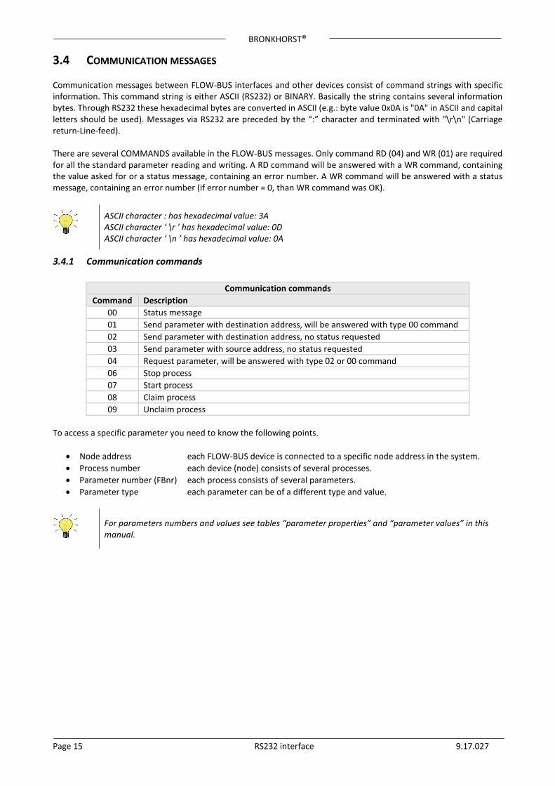
3.4 COMMUNICATION MESSAGES Communication messages between FLOW-BUS interfaces and other devices consist of command strings with specific information. This command string is either ASCII (RS232) or BINARY. Basically the string contains several information bytes. Through RS232 these hexadecimal bytes are converted in ASCII (e.g.: byte value 0x0A is "0A" in ASCII and capital letters should be used). Messages via RS232 are preceded by the “:” character and terminated with "\r\n" (Carriage return-Line-feed). There are several COMMANDS available in the FLOW-BUS messages. Only command RD (04) and WR (01) are required for all the standard parameter reading and writing. A RD command will be answered with a WR command, containing the value asked for or a status message, containing an error number. A WR command will be answered with a status message, containing an error number (if error number = 0, than WR command was OK).
ASCII character : has hexadecimal value: 3A ASCII character ‘ \r ’ has hexadecimal value: 0D ASCII character ‘ \n ’ has hexadecimal value: 0A
3.4.1 Communication commands
Communication commands Command Description
00 Status message 01 Send parameter with destination address, will be answered with type 00 command 02 Send parameter with destination address, no status requested 03 Send parameter with source address, no status requested 04 Request parameter, will be answered with type 02 or 00 command 06 Stop process 07 Start process 08 Claim process 09 Unclaim process
To access a specific parameter you need to know the following points.
• Node address each FLOW-BUS device is connected to a specific node address in the system. • Process number each device (node) consists of several processes. • Parameter number (FBnr) each process consists of several parameters. • Parameter type each parameter can be of a different type and value.
For parameters numbers and values see tables “parameter properties” and “parameter values” in this manual.
BRONKHORST®
Page 16 RS232 interface 9.17.027
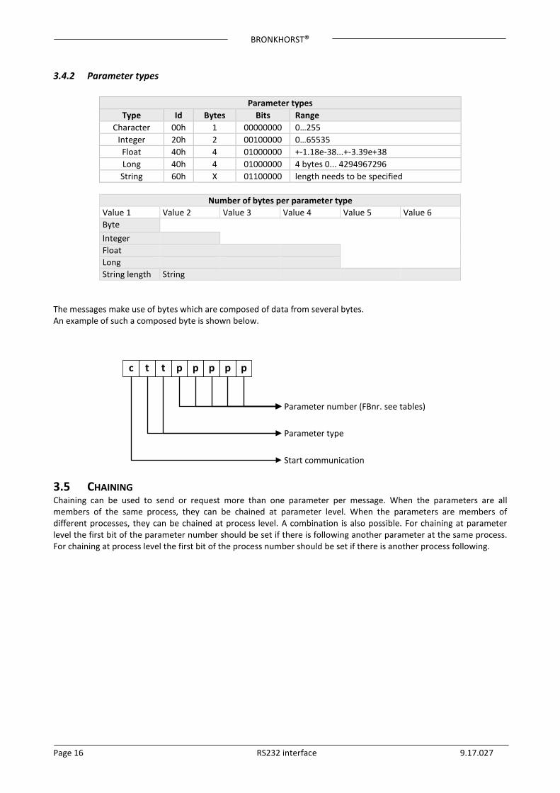
3.4.2 Parameter types
Parameter types Type Id Bytes Bits Range
Character 00h 1 00000000 0…255 Integer 20h 2 00100000 0…65535 Float 40h 4 01000000 +-1.18e-38...+-3.39e+38 Long 40h 4 01000000 4 bytes 0... 4294967296 String 60h X 01100000 length needs to be specified
Number of bytes per parameter type
Value 1 Value 2 Value 3 Value 4 Value 5 Value 6 Byte Integer Float Long String length String
The messages make use of bytes which are composed of data from several bytes. An example of such a composed byte is shown below.
3.5 CHAINING Chaining can be used to send or request more than one parameter per message. When the parameters are all members of the same process, they can be chained at parameter level. When the parameters are members of different processes, they can be chained at process level. A combination is also possible. For chaining at parameter level the first bit of the parameter number should be set if there is following another parameter at the same process. For chaining at process level the first bit of the process number should be set if there is another process following.
c t t p p p p p
Parameter number (FBnr. see tables)
Parameter type
Start communication
BRONKHORST®
Page 17 RS232 interface 9.17.027
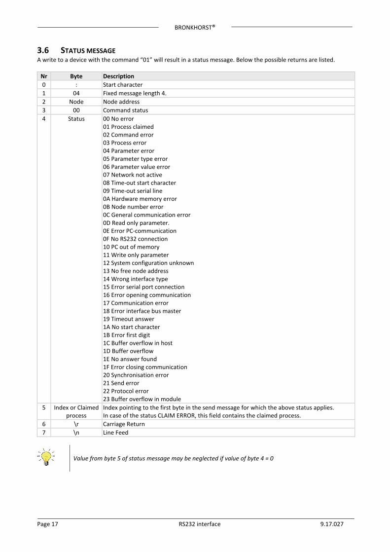
3.6 STATUS MESSAGE A write to a device with the command “01” will result in a status message. Below the possible returns are listed.
Nr Byte Description 0 : Start character 1 04 Fixed message length 4. 2 Node Node address 3 00 Command status 4 Status 00 No error
01 Process claimed 02 Command error 03 Process error 04 Parameter error 05 Parameter type error 06 Parameter value error 07 Network not active 08 Time-out start character 09 Time-out serial line 0A Hardware memory error 0B Node number error 0C General communication error 0D Read only parameter. 0E Error PC-communication 0F No RS232 connection 10 PC out of memory 11 Write only parameter 12 System configuration unknown 13 No free node address 14 Wrong interface type 15 Error serial port connection 16 Error opening communication 17 Communication error 18 Error interface bus master 19 Timeout answer 1A No start character 1B Error first digit 1C Buffer overflow in host 1D Buffer overflow 1E No answer found 1F Error closing communication 20 Synchronisation error 21 Send error 22 Protocol error 23 Buffer overflow in module
5 Index or Claimed process
Index pointing to the first byte in the send message for which the above status applies. In case of the status CLAIM ERROR, this field contains the claimed process.
6 \r Carriage Return 7 \n Line Feed
Value from byte 5 of status message may be neglected if value of byte 4 = 0
BRONKHORST®
Page 18 RS232 interface 9.17.027
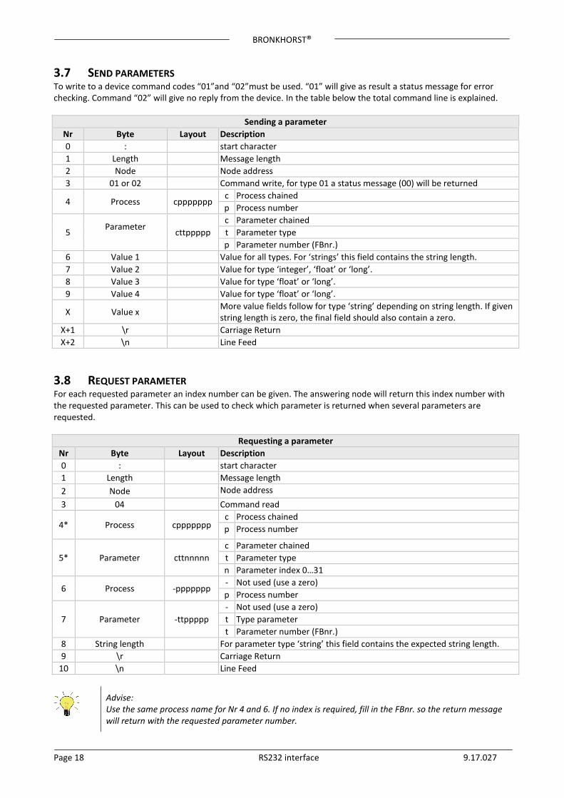
3.7 SEND PARAMETERS To write to a device command codes “01”and “02”must be used. “01” will give as result a status message for error checking. Command “02” will give no reply from the device. In the table below the total command line is explained.
Sending a parameter Nr Byte Layout Description 0 : start character 1 Length Message length 2 Node Node address 3 01 or 02 Command write, for type 01 a status message (00) will be returned
4 Process cppppppp c Process chained p Process number
5 Parameter cttppppp
c Parameter chained t Parameter type p Parameter number (FBnr.)
6 Value 1 Value for all types. For ‘strings’ this field contains the string length. 7 Value 2 Value for type ‘integer’, ‘float’ or ‘long’. 8 Value 3 Value for type ‘float’ or ‘long’. 9 Value 4 Value for type ‘float’ or ‘long’.
X Value x More value fields follow for type ‘string’ depending on string length. If given string length is zero, the final field should also contain a zero.
X+1 \r Carriage Return X+2 \n Line Feed
3.8 REQUEST PARAMETER For each requested parameter an index number can be given. The answering node will return this index number with the requested parameter. This can be used to check which parameter is returned when several parameters are requested.
Requesting a parameter Nr Byte Layout Description 0 : start character 1 Length Message length 2 Node Node address 3 04 Command read
4* Process cppppppp c Process chained p Process number
5* Parameter cttnnnnn c Parameter chained t Parameter type n Parameter index 0…31
6 Process -ppppppp - Not used (use a zero) p Process number
7 Parameter -ttppppp - Not used (use a zero) t Type parameter t Parameter number (FBnr.)
8 String length For parameter type ‘string’ this field contains the expected string length. 9 \r Carriage Return
10 \n Line Feed
Advise: Use the same process name for Nr 4 and 6. If no index is required, fill in the FBnr. so the return message will return with the requested parameter number.
BRONKHORST®
Page 19 RS232 interface 9.17.027
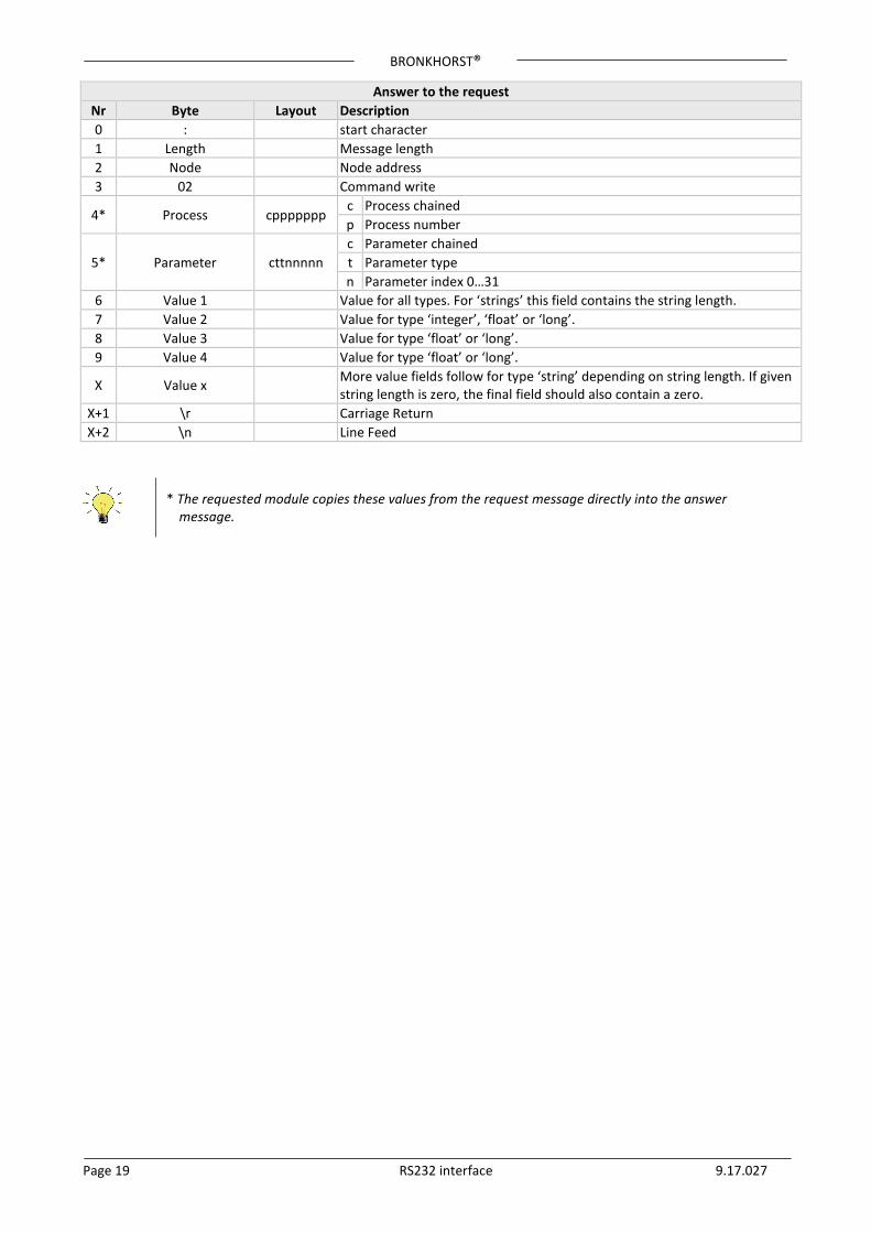
Answer to the request Nr Byte Layout Description 0 : start character 1 Length Message length 2 Node Node address 3 02 Command write
4* Process cppppppp c Process chained p Process number
5* Parameter cttnnnnn c Parameter chained t Parameter type n Parameter index 0…31
6 Value 1 Value for all types. For ‘strings’ this field contains the string length. 7 Value 2 Value for type ‘integer’, ‘float’ or ‘long’. 8 Value 3 Value for type ‘float’ or ‘long’. 9 Value 4 Value for type ‘float’ or ‘long’.
X Value x More value fields follow for type ‘string’ depending on string length. If given string length is zero, the final field should also contain a zero.
X+1 \r Carriage Return X+2 \n Line Feed
* The requested module copies these values from the request message directly into the answer message.
BRONKHORST®
Page 20 RS232 interface 9.17.027
3.9 EXAMPLES – RS232 ASCII PROTOCOL
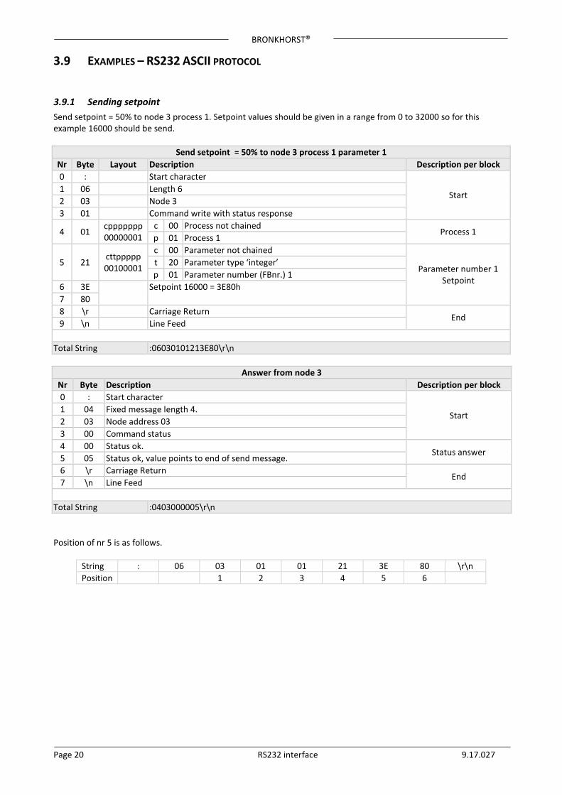
3.9.1 Sending setpoint Send setpoint = 50% to node 3 process 1. Setpoint values should be given in a range from 0 to 32000 so for this example 16000 should be send.
Send setpoint = 50% to node 3 process 1 parameter 1 Nr Byte Layout Description Description per block 0 : Start character
Start 1 06 Length 6 2 03 Node 3 3 01 Command write with status response
4 01 cppppppp 00000001
c 00 Process not chained Process 1
p 01 Process 1
5 21 cttppppp 00100001
c 00 Parameter not chained
Parameter number 1 Setpoint
t 20 Parameter type ‘integer’ p 01 Parameter number (FBnr.) 1
6 3E
Setpoint 16000 = 3E80h 7 80 8 \r Carriage Return
End 9 \n Line Feed
Total String :06030101213E80\r\n
Answer from node 3 Nr Byte Description Description per block 0 : Start character
Start 1 04 Fixed message length 4. 2 03 Node address 03 3 00 Command status 4 00 Status ok.
Status answer 5 05 Status ok, value points to end of send message. 6 \r Carriage Return
End 7 \n Line Feed
Total String :0403000005\r\n Position of nr 5 is as follows.
String : 06 03 01 01 21 3E 80 \r\n Position 1 2 3 4 5 6
BRONKHORST®
Page 21 RS232 interface 9.17.027
3.9.2 Request setpoint
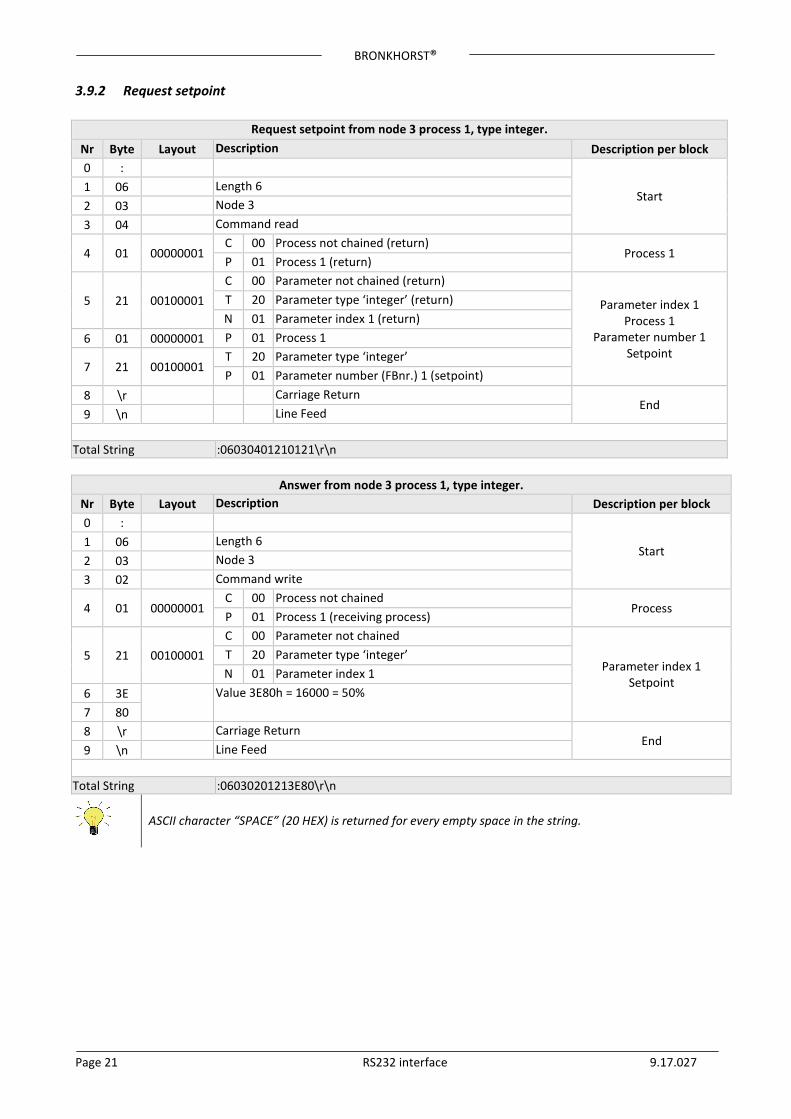
Request setpoint from node 3 process 1, type integer. Nr Byte Layout Description Description per block 0 :
Start 1 06 Length 6 2 03 Node 3 3 04 Command read
4 01 00000001 C 00 Process not chained (return)
Process 1 P 01 Process 1 (return)
5 21 00100001 C 00 Parameter not chained (return)
Parameter index 1 Process 1
Parameter number 1 Setpoint
T 20 Parameter type ‘integer’ (return) N 01 Parameter index 1 (return)
6 01 00000001 P 01 Process 1
7 21 00100001 T 20 Parameter type ‘integer’ P 01 Parameter number (FBnr.) 1 (setpoint)
8 \r Carriage Return End
9 \n Line Feed
Total String :06030401210121\r\n
Answer from node 3 process 1, type integer. Nr Byte Layout Description Description per block 0 :
Start 1 06 Length 6 2 03 Node 3 3 02 Command write
4 01 00000001 C 00 Process not chained
Process P 01 Process 1 (receiving process)
5 21 00100001 C 00 Parameter not chained
Parameter index 1 Setpoint
T 20 Parameter type ‘integer’ N 01 Parameter index 1
6 3E
Value 3E80h = 16000 = 50% 7 80 8 \r Carriage Return
End 9 \n Line Feed
Total String :06030201213E80\r\n
ASCII character “SPACE” (20 HEX) is returned for every empty space in the string.
BRONKHORST®
Page 22 RS232 interface 9.17.027
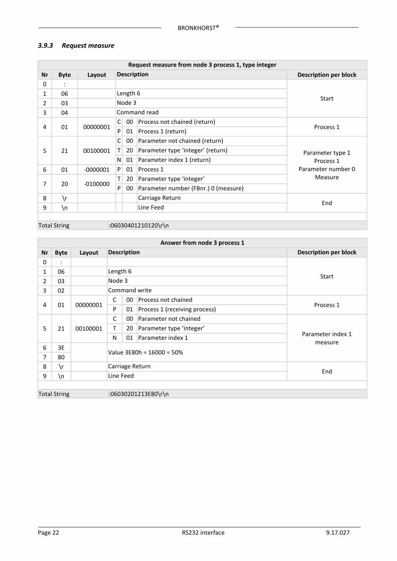
3.9.3 Request measure
Request measure from node 3 process 1, type integer Nr Byte Layout Description Description per block 0 :
Start 1 06 Length 6 2 03 Node 3 3 04 Command read
4 01 00000001 C 00 Process not chained (return)
Process 1 P 01 Process 1 (return)
5 21 00100001 C 00 Parameter not chained (return)
Parameter type 1 Process 1
Parameter number 0 Measure
T 20 Parameter type ‘integer’ (return) N 01 Parameter index 1 (return)
6 01 -0000001 P 01 Process 1
7 20 -0100000 T 20 Parameter type ‘integer’ P 00 Parameter number (FBnr.) 0 (measure)
8 \r Carriage Return End
9 \n Line Feed
Total String :06030401210120\r\n
Answer from node 3 process 1 Nr Byte Layout Description Description per block 0 :
Start 1 06 Length 6 2 03 Node 3 3 02 Command write
4 01 00000001 C 00 Process not chained
Process 1 P 01 Process 1 (receiving process)
5 21 00100001 C 00 Parameter not chained
Parameter index 1 measure
T 20 Parameter type ‘integer’ N 01 Parameter index 1
6 3E Value 3E80h = 16000 = 50%
7 80 8 \r Carriage Return
End 9 \n Line Feed
Total String :06030201213E80\r\n

BRONKHORST®
Page 23 RS232 interface 9.17.027
3.9.4 Request counter value
Request Counter value from node 3, process 104, type float Nr Byte Layout Description Description per block
0 :
Start 1 06 Length 6 2 03 Node 3 3 04 Command read
4 68 01101000 C 00 Process not chained (return)
Process 104 P 68 Process 104 (return)
5 41 01000001 C 00 Parameter not chained (return)
Parameter index 1 Process 104
Parameter number 1 Counter value
T 40 Parameter type ‘float’ (return) N 01 Parameter index 1 (return)
6 68 01101000 P 68 Process 104
7 41 01000001 T 40 Parameter type ‘float’ P 01 Parameter number (FBnr.) 1 (counter value)
8 \r Carriage Return End
9 \n Line Feed
Total String :06030468416841\r\n
Answer from node 3, process 104 Nr Byte Layout Description Description per block 0 :
Start 1 08 Length 8 2 03 Node 3 3 02 Command write
4 68 01101000 C 00 Process not chained
Process 104 P 68 Process 104 (receiving process)
5 41 01000001 C 00 Parameter not chained
Parameter index 1 Counter value
T 40 Parameter type ‘float’ N 01 Parameter index 1
6 45
Parameter value ‘float’ = 5023.96 decimal 7 9C 8 FF 9 AE
10 \r Carriage Return End
11 \n Line Feed
Total String :0803026841459CFFAE\r\n
BRONKHORST®
Page 24 RS232 interface 9.17.027
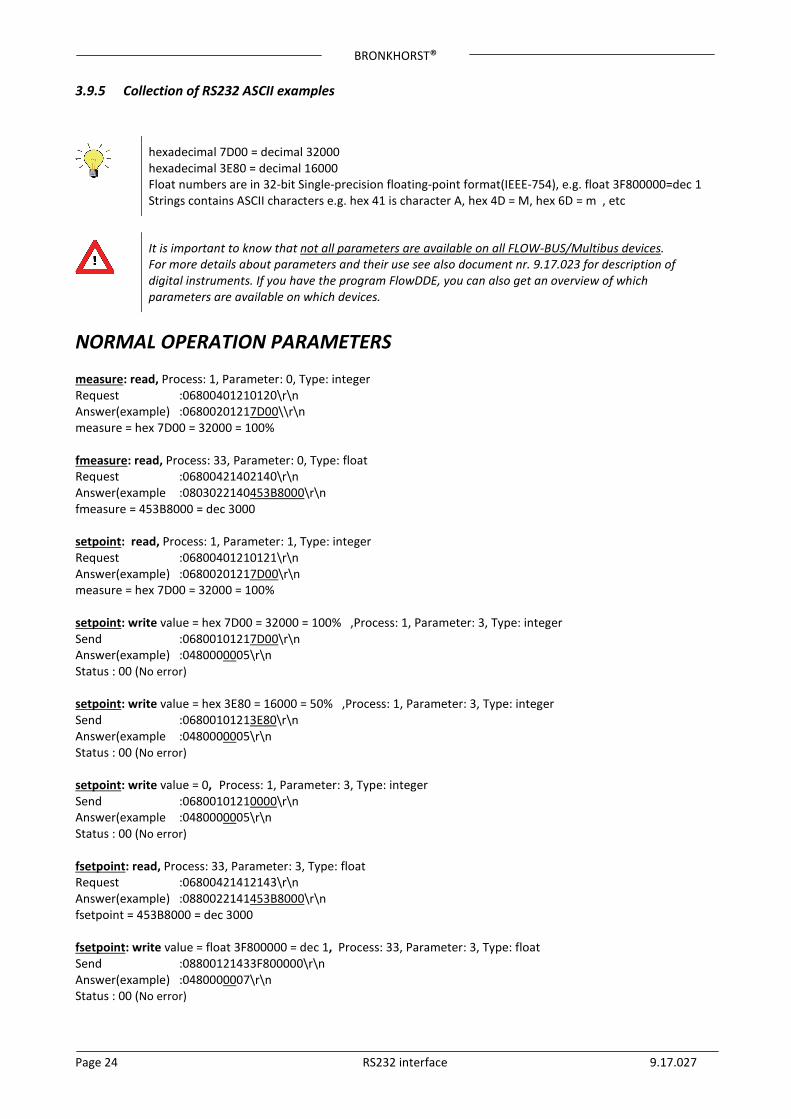
3.9.5 Collection of RS232 ASCII examples
hexadecimal 7D00 = decimal 32000 hexadecimal 3E80 = decimal 16000 Float numbers are in 32-bit Single-precision floating-point format(IEEE-754), e.g. float 3F800000=dec 1 Strings contains ASCII characters e.g. hex 41 is character A, hex 4D = M, hex 6D = m , etc
It is important to know that not all parameters are available on all FLOW-BUS/Multibus devices. For more details about parameters and their use see also document nr. 9.17.023 for description of digital instruments. If you have the program FlowDDE, you can also get an overview of which parameters are available on which devices.
NORMAL OPERATION PARAMETERS measure: read, Process: 1, Parameter: 0, Type: integer Request :06800401210120\r\n Answer(example) :06800201217D00\\r\n measure = hex 7D00 = 32000 = 100% fmeasure: read, Process: 33, Parameter: 0, Type: float Request :06800421402140\r\n Answer(example :0803022140453B8000\r\n fmeasure = 453B8000 = dec 3000 setpoint: read, Process: 1, Parameter: 1, Type: integer Request :06800401210121\r\n Answer(example) :06800201217D00\r\n measure = hex 7D00 = 32000 = 100% setpoint: write value = hex 7D00 = 32000 = 100% ,Process: 1, Parameter: 3, Type: integer Send :06800101217D00\r\n Answer(example) :0480000005\r\n Status : 00 (No error) setpoint: write value = hex 3E80 = 16000 = 50% ,Process: 1, Parameter: 3, Type: integer Send :06800101213E80\r\n Answer(example :0480000005\r\n Status : 00 (No error) setpoint: write value = 0, Process: 1, Parameter: 3, Type: integer Send :06800101210000\r\n Answer(example :0480000005\r\n Status : 00 (No error) fsetpoint: read, Process: 33, Parameter: 3, Type: float Request :06800421412143\r\n Answer(example) :0880022141453B8000\r\n fsetpoint = 453B8000 = dec 3000 fsetpoint: write value = float 3F800000 = dec 1, Process: 33, Parameter: 3, Type: float Send :08800121433F800000\r\n Answer(example) :0480000007\r\n Status : 00 (No error)
BRONKHORST®
Page 25 RS232 interface 9.17.027
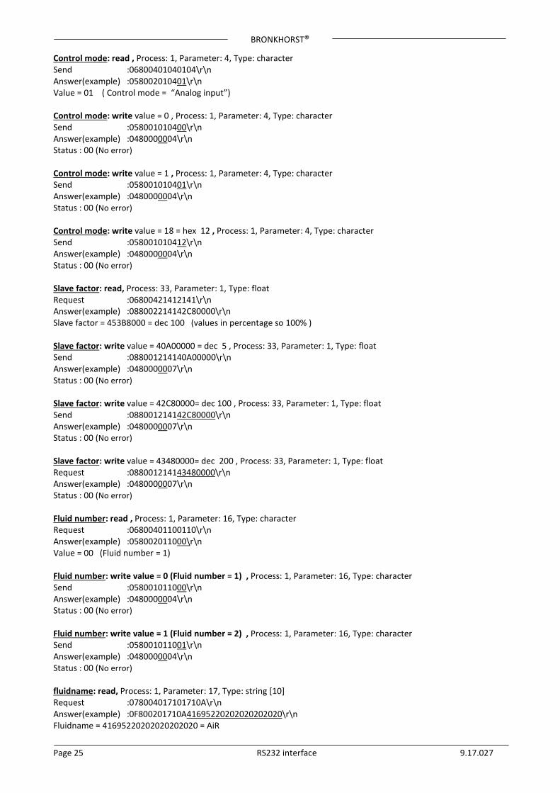
Control mode: read , Process: 1, Parameter: 4, Type: character Send :06800401040104\r\n Answer(example) :058002010401\r\n Value = 01 ( Control mode = “Analog input”) Control mode: write value = 0 , Process: 1, Parameter: 4, Type: character Send :058001010400\r\n Answer(example) :0480000004\r\n Status : 00 (No error) Control mode: write value = 1 , Process: 1, Parameter: 4, Type: character Send :058001010401\r\n Answer(example) :0480000004\r\n Status : 00 (No error) Control mode: write value = 18 = hex 12 , Process: 1, Parameter: 4, Type: character Send :058001010412\r\n Answer(example) :0480000004\r\n Status : 00 (No error) Slave factor: read, Process: 33, Parameter: 1, Type: float Request :06800421412141\r\n Answer(example) :088002214142C80000\r\n Slave factor = 453B8000 = dec 100 (values in percentage so 100% ) Slave factor: write value = 40A00000 = dec 5 , Process: 33, Parameter: 1, Type: float Send :088001214140A00000\r\n Answer(example) :0480000007\r\n Status : 00 (No error) Slave factor: write value = 42C80000= dec 100 , Process: 33, Parameter: 1, Type: float Send :088001214142C80000\r\n Answer(example) :0480000007\r\n Status : 00 (No error) Slave factor: write value = 43480000= dec 200 , Process: 33, Parameter: 1, Type: float Request :088001214143480000\r\n Answer(example) :0480000007\r\n Status : 00 (No error) Fluid number: read , Process: 1, Parameter: 16, Type: character Request :06800401100110\r\n Answer(example) :058002011000\r\n Value = 00 (Fluid number = 1) Fluid number: write value = 0 (Fluid number = 1) , Process: 1, Parameter: 16, Type: character Send :058001011000\r\n Answer(example) :0480000004\r\n Status : 00 (No error) Fluid number: write value = 1 (Fluid number = 2) , Process: 1, Parameter: 16, Type: character Send :058001011001\r\n Answer(example) :0480000004\r\n Status : 00 (No error) fluidname: read, Process: 1, Parameter: 17, Type: string [10] Request :078004017101710A\r\n Answer(example) :0F800201710A41695220202020202020\r\n Fluidname = 41695220202020202020 = AiR
BRONKHORST®
Page 26 RS232 interface 9.17.027
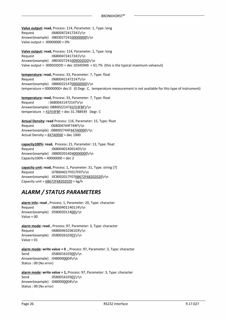
Valve output: read, Process: 114, Parameter: 1, Type: long Request :06800472417241\r\n Answer(example) :080302724100000000\r\n Valve output = 00000000 = 0% Valve output: read, Process: 114, Parameter: 1, Type: long Request :06800472417241\r\n Answer(example) :0803027241009DDDDD\r\n Valve output = 009DDDDD = dec 10345949 = 61.7% (this is the typical maximum valveout) temperature: read, Process: 33, Parameter: 7, Type: float Request :06800421472147\r\n Answer(example) :088002214700000000\r\n temperature = 00000000= dec 0 (0 Degr. C, temperature measurement is not available for this type of instrument) temperature: read, Process: 33, Parameter: 7, Type: float Request : 06800421472147\r\n Answer(example) :088002214741FE4FBF\r\n temperature = 41FE4FBF = dec 31.788939 Degr. C Actual Density: read Process: 116, Parameter: 15, Type: float Request :068004744F744F\r\n Answer(example) :088002744F447A0000\r\n Actual Density = 447A0000 = dec 1000 capacity100%: read, Process: 21, Parameter: 13, Type: float Request :068004014D014D\r\n Answer(example) :088002014D40000000\r\n Capacity100% = 40000000 = dec 2 capacity unit: read, Process: 1, Parameter: 31, Type: string [7] Request :078004017F017F07\r\n Answer(example) :0C8002017F076B672F68202020\r\n Capacity unit = 6B672F68202020 = kg/h
ALARM / STATUS PARAMETERS alarm info: read , Process: 1, Parameter: 20, Type: character Request :06800401140114\r\n Answer(example) :058002011400\r\n Value = 00 alarm mode: read , Process: 97, Parameter: 3, Type: character Request :06800461036103\r\n Answer(example) :058002610301\r\n Value = 01 alarm mode: write value = 0 , Process: 97, Parameter: 3, Type: character Send :058001610300\r\n Answer(example) :0480000004\r\n Status : 00 (No error) alarm mode: write value = 1, Process: 97, Parameter: 3, Type: character Send :058001610301\r\n Answer(example) :0480000004\r\n Status : 00 (No error)
BRONKHORST®
Page 27 RS232 interface 9.17.027
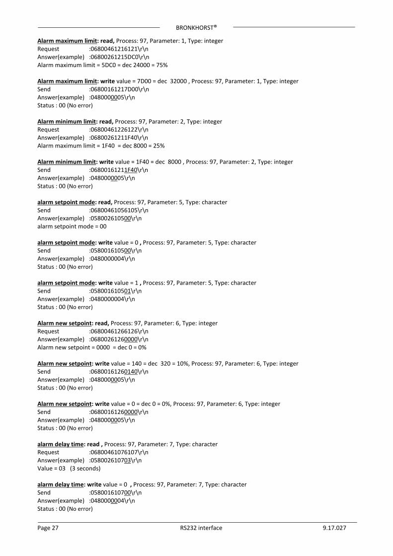
Alarm maximum limit: read, Process: 97, Parameter: 1, Type: integer Request :06800461216121\r\n Answer(example) :06800261215DC0\r\n Alarm maximum limit = 5DC0 = dec 24000 = 75% Alarm maximum limit: write value = 7D00 = dec 32000 , Process: 97, Parameter: 1, Type: integer Send :06800161217D00\r\n Answer(example) :0480000005\r\n Status : 00 (No error) Alarm minimum limit: read, Process: 97, Parameter: 2, Type: integer Request :06800461226122\r\n Answer(example) :06800261211F40\r\n Alarm maximum limit = 1F40 = dec 8000 = 25% Alarm minimum limit: write value = 1F40 = dec 8000 , Process: 97, Parameter: 2, Type: integer Send :06800161211F40\r\n Answer(example) :0480000005\r\n Status : 00 (No error) alarm setpoint mode: read, Process: 97, Parameter: 5, Type: character Send :06800461056105\r\n Answer(example) :058002610500\r\n alarm setpoint mode = 00 alarm setpoint mode: write value = 0 , Process: 97, Parameter: 5, Type: character Send :058001610500\r\n Answer(example) :0480000004\r\n Status : 00 (No error) alarm setpoint mode: write value = 1 , Process: 97, Parameter: 5, Type: character Send :058001610501\r\n Answer(example) :0480000004\r\n Status : 00 (No error) Alarm new setpoint: read, Process: 97, Parameter: 6, Type: integer Request :06800461266126\r\n Answer(example) :06800261260000\r\n Alarm new setpoint = 0000 = dec 0 = 0% Alarm new setpoint: write value = 140 = dec 320 = 10%, Process: 97, Parameter: 6, Type: integer Send :06800161260140\r\n Answer(example) :0480000005\r\n Status : 00 (No error) Alarm new setpoint: write value = 0 = dec 0 = 0%, Process: 97, Parameter: 6, Type: integer Send :06800161260000\r\n Answer(example) :0480000005\r\n Status : 00 (No error) alarm delay time: read , Process: 97, Parameter: 7, Type: character Request :06800461076107\r\n Answer(example) :058002610703\r\n Value = 03 (3 seconds) alarm delay time: write value = 0 , Process: 97, Parameter: 7, Type: character Send :058001610700\r\n Answer(example) :0480000004\r\n Status : 00 (No error)
BRONKHORST®
Page 28 RS232 interface 9.17.027
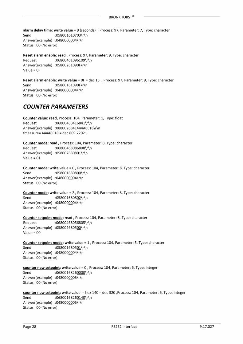
alarm delay time: write value = 3 (seconds) , Process: 97, Parameter: 7, Type: character Send :058001610703\r\n Answer(example) :0480000004\r\n Status : 00 (No error) Reset alarm enable: read , Process: 97, Parameter: 9, Type: character Request :06800461096109\r\n Answer(example) :05800261090F\r\n Value = 0F Reset alarm enable: write value = 0F = dec 15 , Process: 97, Parameter: 9, Type: character Send :05800161090F\r\n Answer(example) :0480000004\r\n Status : 00 (No error)
COUNTER PARAMETERS Counter value: read, Process: 104, Parameter: 1, Type: float Request :06800468416841\r\n Answer(example) :0880026841444A6E18\r\n fmeasure= 444A6E18 = dec 809.72021 Counter mode: read , Process: 104, Parameter: 8, Type: character Request :06800468086808\r\n Answer(example) :058002680801\r\n Value = 01 Counter mode: write value = 0 , Process: 104, Parameter: 8, Type: character Send :058001680800\r\n Answer(example) :0480000004\r\n Status : 00 (No error) Counter mode: write value = 2 , Process: 104, Parameter: 8, Type: character Send :058001680802\r\n Answer(example) :0480000004\r\n Status : 00 (No error) Counter setpoint mode: read , Process: 104, Parameter: 5, Type: character Request :06800468056805\r\n Answer(example) :058002680500\r\n Value = 00 Counter setpoint mode: write value = 1 , Process: 104, Parameter: 5, Type: character Send :058001680501\r\n Answer(example) :0480000004\r\n Status : 00 (No error) counter new setpoint: write value = 0 , Process: 104, Parameter: 6, Type: integer Send :06800168260000\r\n Answer(example) :0480000005\r\n Status : 00 (No error) counter new setpoint: write value = hex 140 = dec 320 ,Process: 104, Parameter: 6, Type: integer Send :06800168260140\r\n Answer(example) :0480000005\r\n Status : 00 (No error)
BRONKHORST®
Page 29 RS232 interface 9.17.027
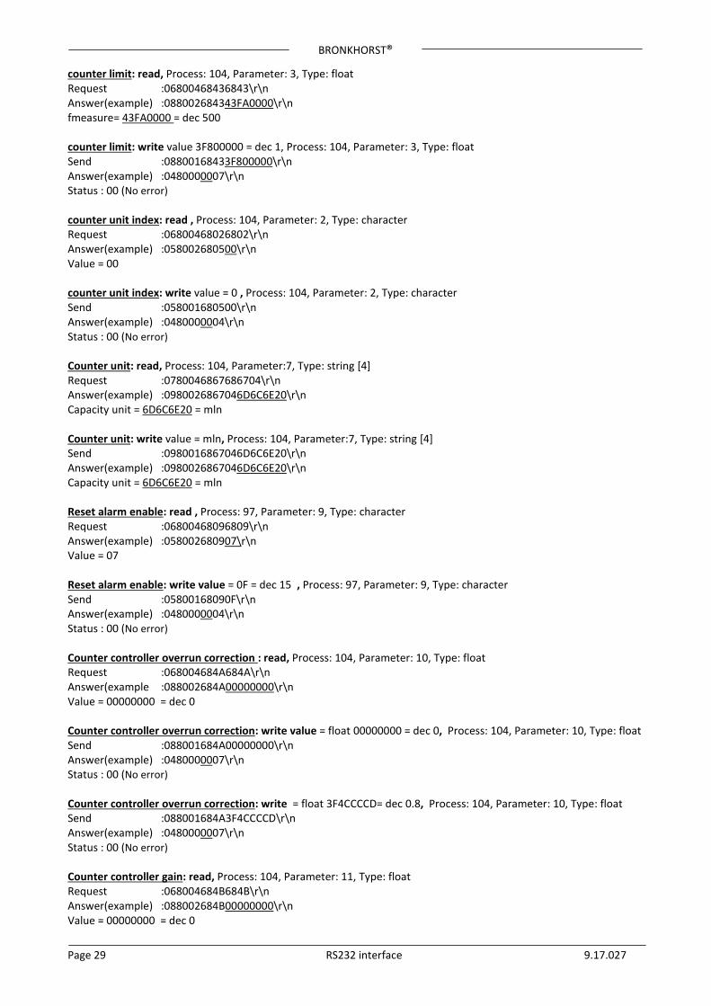
counter limit: read, Process: 104, Parameter: 3, Type: float Request :06800468436843\r\n Answer(example) :088002684343FA0000\r\n fmeasure= 43FA0000 = dec 500 counter limit: write value 3F800000 = dec 1, Process: 104, Parameter: 3, Type: float Send :08800168433F800000\r\n Answer(example) :0480000007\r\n Status : 00 (No error) counter unit index: read , Process: 104, Parameter: 2, Type: character Request :06800468026802\r\n Answer(example) :058002680500\r\n Value = 00 counter unit index: write value = 0 , Process: 104, Parameter: 2, Type: character Send :058001680500\r\n Answer(example) :0480000004\r\n Status : 00 (No error) Counter unit: read, Process: 104, Parameter:7, Type: string [4] Request :0780046867686704\r\n Answer(example) :0980026867046D6C6E20\r\n Capacity unit = 6D6C6E20 = mln Counter unit: write value = mln, Process: 104, Parameter:7, Type: string [4] Send :0980016867046D6C6E20\r\n Answer(example) :0980026867046D6C6E20\r\n Capacity unit = 6D6C6E20 = mln Reset alarm enable: read , Process: 97, Parameter: 9, Type: character Request :06800468096809\r\n Answer(example) :058002680907\r\n Value = 07 Reset alarm enable: write value = 0F = dec 15 , Process: 97, Parameter: 9, Type: character Send :05800168090F\r\n Answer(example) :0480000004\r\n Status : 00 (No error) Counter controller overrun correction : read, Process: 104, Parameter: 10, Type: float Request :068004684A684A\r\n Answer(example :088002684A00000000\r\n Value = 00000000 = dec 0 Counter controller overrun correction: write value = float 00000000 = dec 0, Process: 104, Parameter: 10, Type: float Send :088001684A00000000\r\n Answer(example) :0480000007\r\n Status : 00 (No error) Counter controller overrun correction: write = float 3F4CCCCD= dec 0.8, Process: 104, Parameter: 10, Type: float Send :088001684A3F4CCCCD\r\n Answer(example) :0480000007\r\n Status : 00 (No error) Counter controller gain: read, Process: 104, Parameter: 11, Type: float Request :068004684B684B\r\n Answer(example) :088002684B00000000\r\n Value = 00000000 = dec 0
BRONKHORST®
Page 30 RS232 interface 9.17.027
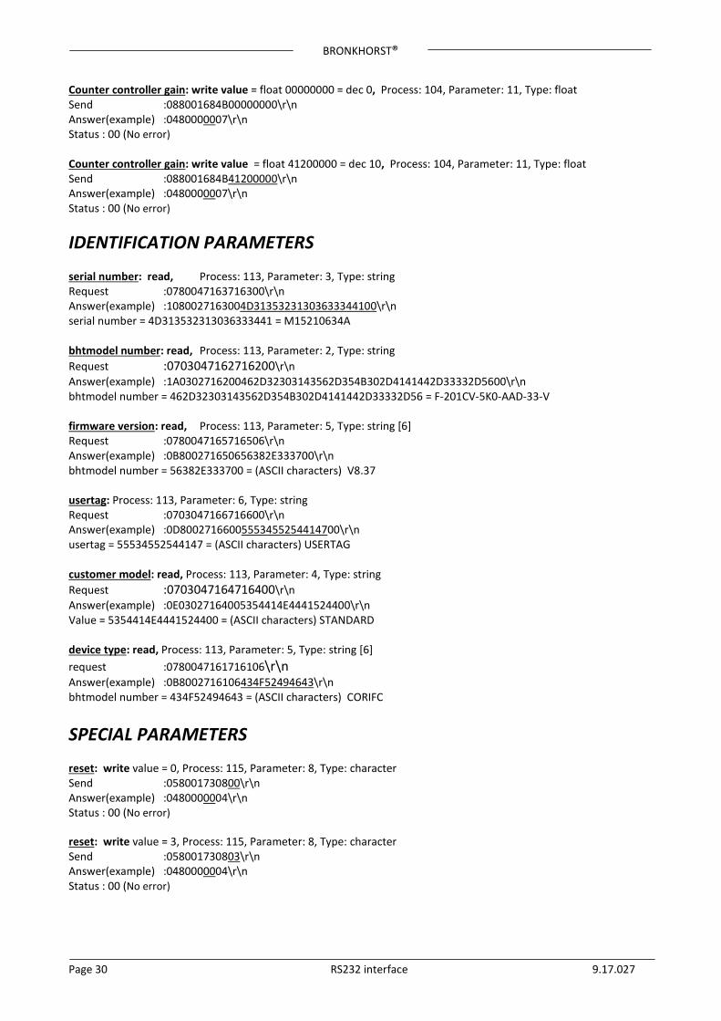
Counter controller gain: write value = float 00000000 = dec 0, Process: 104, Parameter: 11, Type: float Send :088001684B00000000\r\n Answer(example) :0480000007\r\n Status : 00 (No error) Counter controller gain: write value = float 41200000 = dec 10, Process: 104, Parameter: 11, Type: float Send :088001684B41200000\r\n Answer(example) :0480000007\r\n Status : 00 (No error)
IDENTIFICATION PARAMETERS serial number: read, Process: 113, Parameter: 3, Type: string Request :0780047163716300\r\n Answer(example) :1080027163004D31353231303633344100\r\n serial number = 4D313532313036333441 = M15210634A bhtmodel number: read, Process: 113, Parameter: 2, Type: string Request :0703047162716200\r\n Answer(example) :1A0302716200462D32303143562D354B302D4141442D33332D5600\r\n bhtmodel number = 462D32303143562D354B302D4141442D33332D56 = F-201CV-5K0-AAD-33-V firmware version: read, Process: 113, Parameter: 5, Type: string [6] Request :0780047165716506\r\n Answer(example) :0B800271650656382E333700\r\n bhtmodel number = 56382E333700 = (ASCII characters) V8.37 usertag: Process: 113, Parameter: 6, Type: string Request :0703047166716600\r\n Answer(example) :0D80027166005553455254414700\r\n usertag = 55534552544147 = (ASCII characters) USERTAG customer model: read, Process: 113, Parameter: 4, Type: string Request :0703047164716400\r\n Answer(example) :0E03027164005354414E4441524400\r\n Value = 5354414E4441524400 = (ASCII characters) STANDARD device type: read, Process: 113, Parameter: 5, Type: string [6] request :0780047161716106\r\n Answer(example) :0B8002716106434F52494643\r\n bhtmodel number = 434F52494643 = (ASCII characters) CORIFC SPECIAL PARAMETERS reset: write value = 0, Process: 115, Parameter: 8, Type: character Send :058001730800\r\n Answer(example) :0480000004\r\n Status : 00 (No error) reset: write value = 3, Process: 115, Parameter: 8, Type: character Send :058001730803\r\n Answer(example) :0480000004\r\n Status : 00 (No error)
BRONKHORST®
Page 31 RS232 interface 9.17.027
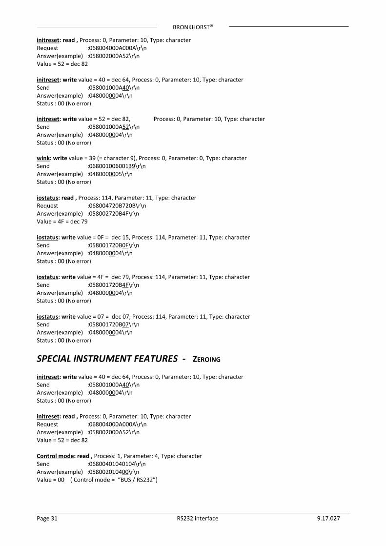
initreset: read , Process: 0, Parameter: 10, Type: character Request :068004000A000A\r\n Answer(example) :058002000A52\r\n Value = 52 = dec 82 initreset: write value = 40 = dec 64, Process: 0, Parameter: 10, Type: character Send :058001000A40\r\n Answer(example) :0480000004\r\n Status : 00 (No error) initreset: write value = 52 = dec 82, Process: 0, Parameter: 10, Type: character Send :058001000A52\r\n Answer(example) :0480000004\r\n Status : 00 (No error) wink: write value = 39 (= character 9), Process: 0, Parameter: 0, Type: character Send :06800100600139\r\n Answer(example) :0480000005\r\n Status : 00 (No error) iostatus: read , Process: 114, Parameter: 11, Type: character Request :068004720B720B\r\n Answer(example) :058002720B4F\r\n Value = 4F = dec 79 iostatus: write value = 0F = dec 15, Process: 114, Parameter: 11, Type: character Send :058001720B0F\r\n Answer(example) :0480000004\r\n Status : 00 (No error) iostatus: write value = 4F = dec 79, Process: 114, Parameter: 11, Type: character Send :058001720B4F\r\n Answer(example) :0480000004\r\n Status : 00 (No error) iostatus: write value = 07 = dec 07, Process: 114, Parameter: 11, Type: character Send :058001720B07\r\n Answer(example) :0480000004\r\n Status : 00 (No error)
SPECIAL INSTRUMENT FEATURES - ZEROING initreset: write value = 40 = dec 64, Process: 0, Parameter: 10, Type: character Send :058001000A40\r\n Answer(example) :0480000004\r\n Status : 00 (No error) initreset: read , Process: 0, Parameter: 10, Type: character Request :068004000A000A\r\n Answer(example) :058002000A52\r\n Value = 52 = dec 82 Control mode: read , Process: 1, Parameter: 4, Type: character Send :06800401040104\r\n Answer(example) :058002010400\r\n Value = 00 ( Control mode = “BUS / RS232”)
BRONKHORST®
Page 32 RS232 interface 9.17.027
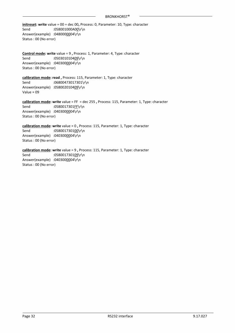
initreset: write value = 00 = dec 00, Process: 0, Parameter: 10, Type: character Send :058001000A00\r\n Answer(example) :0480000004\r\n Status : 00 (No error) Control mode: write value = 9 , Process: 1, Parameter: 4, Type: character Send :050301010409\r\n Answer(example) :0403000004\r\n Status : 00 (No error) calibration mode: read , Process: 115, Parameter: 1, Type: character Send :06800473017301\r\n Answer(example) :058002010409\r\n Value = 09 calibration mode: write value = FF = dec 255 , Process: 115, Parameter: 1, Type: character Send :0580017301FF\r\n Answer(example) :0403000004\r\n Status : 00 (No error) calibration mode: write value = 0 , Process: 115, Parameter: 1, Type: character Send :058001730100\r\n Answer(example) :0403000004\r\n Status : 00 (No error) calibration mode: write value = 9 , Process: 115, Parameter: 1, Type: character Send :058001730109\r\n Answer(example) :0403000004\r\n Status : 00 (No error)
BRONKHORST®
Page 33 RS232 interface 9.17.027
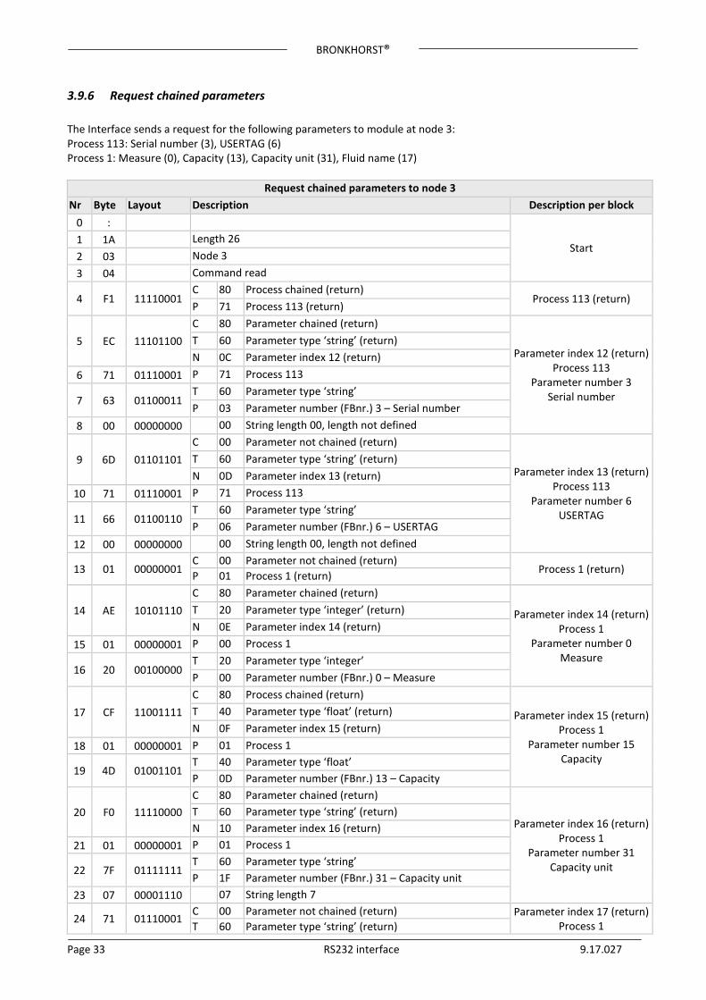
3.9.6 Request chained parameters The Interface sends a request for the following parameters to module at node 3: Process 113: Serial number (3), USERTAG (6) Process 1: Measure (0), Capacity (13), Capacity unit (31), Fluid name (17)
Request chained parameters to node 3 Nr Byte Layout Description Description per block
0 :
Start 1 1A Length 26 2 03 Node 3 3 04 Command read
4 F1 11110001 C 80 Process chained (return)
Process 113 (return) P 71 Process 113 (return)
5 EC 11101100 C 80 Parameter chained (return)
Parameter index 12 (return) Process 113
Parameter number 3 Serial number
T 60 Parameter type ‘string’ (return) N 0C Parameter index 12 (return)
6 71 01110001 P 71 Process 113
7 63 01100011 T 60 Parameter type ‘string’ P 03 Parameter number (FBnr.) 3 – Serial number
8 00 00000000 00 String length 00, length not defined
9 6D 01101101 C 00 Parameter not chained (return)
Parameter index 13 (return) Process 113
Parameter number 6 USERTAG
T 60 Parameter type ‘string’ (return) N 0D Parameter index 13 (return)
10 71 01110001 P 71 Process 113
11 66 01100110 T 60 Parameter type ‘string’ P 06 Parameter number (FBnr.) 6 – USERTAG
12 00 00000000 00 String length 00, length not defined
13 01 00000001 C 00 Parameter not chained (return)
Process 1 (return) P 01 Process 1 (return)
14 AE 10101110 C 80 Parameter chained (return)
Parameter index 14 (return) Process 1
Parameter number 0 Measure
T 20 Parameter type ‘integer’ (return) N 0E Parameter index 14 (return)
15 01 00000001 P 00 Process 1
16 20 00100000 T 20 Parameter type ‘integer’ P 00 Parameter number (FBnr.) 0 – Measure
17 CF 11001111 C 80 Process chained (return)
Parameter index 15 (return) Process 1
Parameter number 15 Capacity
T 40 Parameter type ‘float’ (return) N 0F Parameter index 15 (return)
18 01 00000001 P 01 Process 1
19 4D 01001101 T 40 Parameter type ‘float’ P 0D Parameter number (FBnr.) 13 – Capacity
20 F0 11110000 C 80 Parameter chained (return)
Parameter index 16 (return) Process 1
Parameter number 31 Capacity unit
T 60 Parameter type ‘string’ (return) N 10 Parameter index 16 (return)
21 01 00000001 P 01 Process 1
22 7F 01111111 T 60 Parameter type ‘string’ P 1F Parameter number (FBnr.) 31 – Capacity unit
23 07 00001110 07 String length 7
24 71 01110001 C 00 Parameter not chained (return) Parameter index 17 (return)
Process 1 T 60 Parameter type ‘string’ (return)
BRONKHORST®
Page 34 RS232 interface 9.17.027
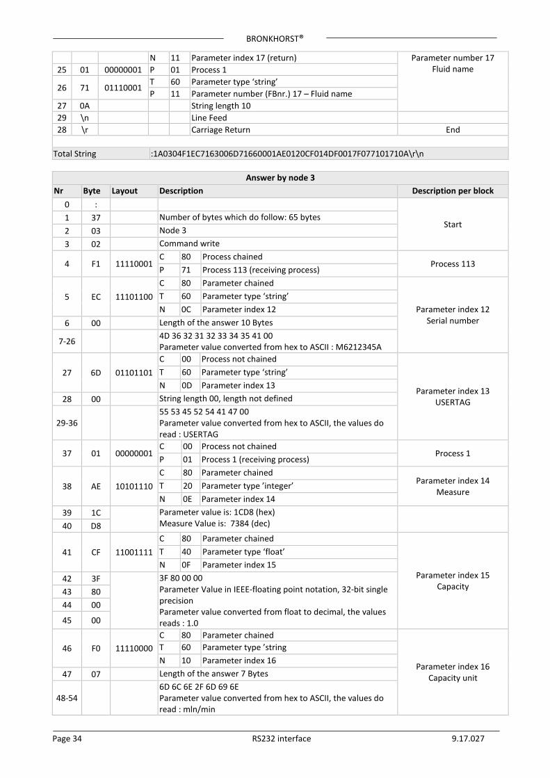
N 11 Parameter index 17 (return) Parameter number 17 Fluid name 25 01 00000001 P 01 Process 1
26 71 01110001 T 60 Parameter type ‘string’ P 11 Parameter number (FBnr.) 17 – Fluid name
27 0A String length 10 29 \n Line Feed 28 \r Carriage Return End
Total String :1A0304F1EC7163006D71660001AE0120CF014DF0017F077101710A\r\n
Answer by node 3 Nr Byte Layout Description Description per block
0 :
Start 1 37 Number of bytes which do follow: 65 bytes 2 03 Node 3 3 02 Command write
4 F1 11110001 C 80 Process chained
Process 113 P 71 Process 113 (receiving process)
5 EC 11101100 C 80 Parameter chained
Parameter index 12 Serial number
T 60 Parameter type ‘string’ N 0C Parameter index 12
6 00 Length of the answer 10 Bytes
7-26 4D 36 32 31 32 33 34 35 41 00 Parameter value converted from hex to ASCII : M6212345A
27 6D 01101101 C 00 Process not chained
Parameter index 13 USERTAG
T 60 Parameter type ‘string’ N 0D Parameter index 13
28 00 String length 00, length not defined
29-36 55 53 45 52 54 41 47 00 Parameter value converted from hex to ASCII, the values do read : USERTAG
37 01 00000001 C 00 Process not chained
Process 1 P 01 Process 1 (receiving process)
38 AE 10101110 C 80 Parameter chained
Parameter index 14 Measure
T 20 Parameter type ’integer’ N 0E Parameter index 14
39 1C
Parameter value is: 1CD8 (hex) Measure Value is: 7384 (dec)
40 D8
41 CF 11001111 C 80 Parameter chained
Parameter index 15 Capacity
T 40 Parameter type ‘float’ N 0F Parameter index 15
42 3F
3F 80 00 00 Parameter Value in IEEE-floating point notation, 32-bit single precision Parameter value converted from float to decimal, the values reads : 1.0
43 80 44 00
45 00
46 F0 11110000 C 80 Parameter chained
Parameter index 16 Capacity unit
T 60 Parameter type ’string N 10 Parameter index 16
47 07 Length of the answer 7 Bytes
48-54 6D 6C 6E 2F 6D 69 6E Parameter value converted from hex to ASCII, the values do read : mln/min

BRONKHORST®
Page 35 RS232 interface 9.17.027
55 71 01110001 C 00 Parameter not chained
Parameter index 17 Fluid name
T 60 Parameter type ’string’ N 11 Parameter index 17
56 0A Length of the answer 10 Bytes
57-66 4E 32 20 20 20 20 20 20 20 20 Parameter value converted from hex to ASCII, the values do read: N2
Total String :370302F1EC004D3632313233343541006D00555345525441470001AE1CD8CF3F800000F0076
D6C6E2F6D696E710A4E322020202020202020\r\n
3.9.7 Example Request chained parameters, setpoint and measure setpoint: Process: 1, Parameter: 1, Type: integer measure: Process: 1, Parameter: 0, Type: integer Chained Request to read setpoint and measure: Request :0A80048121012101210120\r\n Answer(example) :0A800281213E8001213E80\r\n setpoint = 3E80 = dec. 16000 = 50% measure = 3E80 = dec. 16000= 50%
3.9.8 Example Request chained parameters, measure and temperature measure : Process: 1, Parameter: 0, Type: integer temperature : Process: 33, Parameter: 7, Type: float Chained Request to read measure and temperature: Request :0A80048121012021472147\r\n Answer(example) :0C800281213E80214742033089\r\n measure = 3E80 = dec. 16000 = 50% temperature = 42033089 = dec. 32.797398 (Degr.C) Note: Temperature parameter value is in IEEE-floating point notation, 32-bit single precision
3.9.9 Example Request chained parameters, fmeasure and temperature fmeasure : Process: 33, Parameter: 0, Type: float temperature : Process: 33, Parameter: 7, Type: float Chained Request to read fmeasure and temperature: Request :0A8004A14021402no1472147\r\n Answer(example) :0E8002A14041000000214741F30956\r\n fmeasure = 41000000 = dec. 8 temperature = 41F30956 = dec. 30.379559 (Degr.C)
BRONKHORST®
Page 36 RS232 interface 9.17.027
3.10 EXAMPLES - RS232 ENHANCED BINARY PROTOCOL
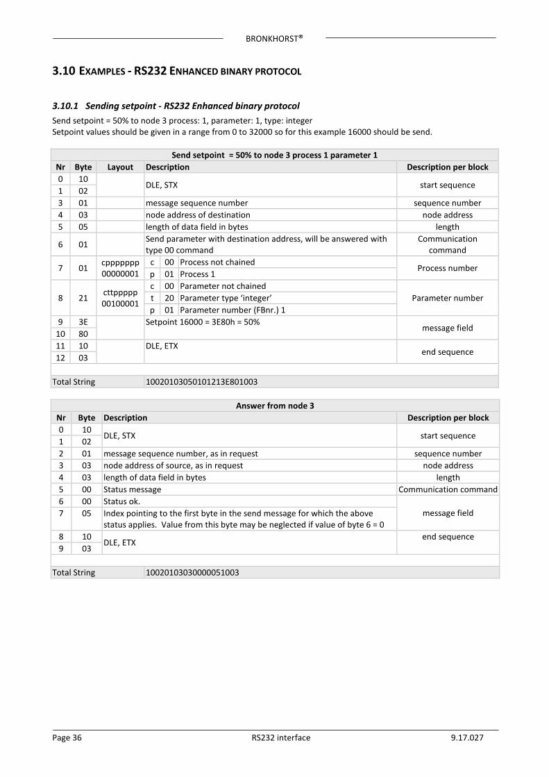
3.10.1 Sending setpoint - RS232 Enhanced binary protocol Send setpoint = 50% to node 3 process: 1, parameter: 1, type: integer Setpoint values should be given in a range from 0 to 32000 so for this example 16000 should be send.
Send setpoint = 50% to node 3 process 1 parameter 1 Nr Byte Layout Description Description per block 0 10
DLE, STX start sequence 1 02 3 01 message sequence number sequence number 4 03 node address of destination node address 5 05 length of data field in bytes length
6 01 Send parameter with destination address, will be answered with type 00 command
Communication command
7 01 cppppppp 00000001
c 00 Process not chained Process number
p 01 Process 1
8 21 cttppppp 00100001
c 00 Parameter not chained Parameter number t 20 Parameter type ‘integer’
p 01 Parameter number (FBnr.) 1 9 3E
Setpoint 16000 = 3E80h = 50%
message field 10 80 11 10
DLE, ETX
end sequence 12 03
Total String 10020103050101213E801003
Answer from node 3 Nr Byte Description Description per block 0 10
DLE, STX start sequence 1 02 2 01 message sequence number, as in request sequence number 3 03 node address of source, as in request node address 4 03 length of data field in bytes length 5 00 Status message Communication command 6 00 Status ok.
message field 7 05 Index pointing to the first byte in the send message for which the above status applies. Value from this byte may be neglected if value of byte 6 = 0
8 10 DLE, ETX
end sequence 9 03
Total String 10020103030000051003
BRONKHORST®
Page 37 RS232 interface 9.17.027
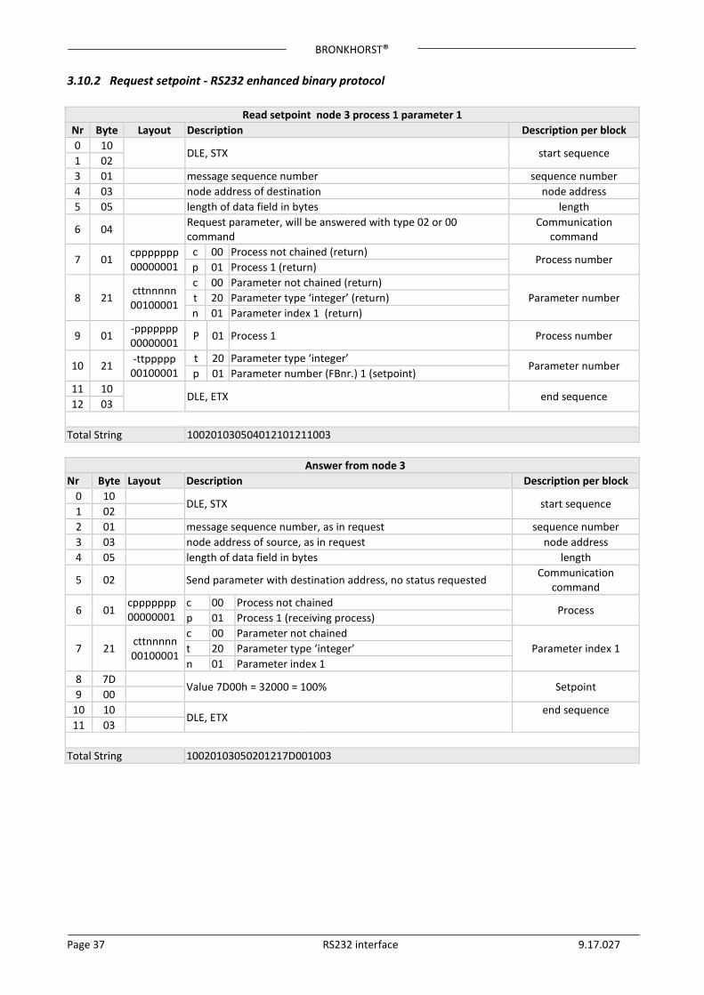
3.10.2 Request setpoint - RS232 enhanced binary protocol
Read setpoint node 3 process 1 parameter 1 Nr Byte Layout Description Description per block 0 10
DLE, STX start sequence 1 02 3 01 message sequence number sequence number 4 03 node address of destination node address 5 05 length of data field in bytes length
6 04 Request parameter, will be answered with type 02 or 00 command
Communication command
7 01 cppppppp 00000001
c 00 Process not chained (return) Process number
p 01 Process 1 (return)
8 21 cttnnnnn 00100001
c 00 Parameter not chained (return) Parameter number t 20 Parameter type ‘integer’ (return)
n 01 Parameter index 1 (return)
9 01 -ppppppp 00000001 P 01 Process 1 Process number
10 21 -ttppppp 00100001
t 20 Parameter type ‘integer’ Parameter number
p 01 Parameter number (FBnr.) 1 (setpoint) 11 10
DLE, ETX end sequence 12 03
Total String 100201030504012101211003
Answer from node 3 Nr Byte Layout Description Description per block
0 10 DLE, STX start sequence
1 02 2 01 message sequence number, as in request sequence number 3 03 node address of source, as in request node address 4 05 length of data field in bytes length
5 02 Send parameter with destination address, no status requested Communication command
6 01 cppppppp 00000001
c 00 Process not chained Process
p 01 Process 1 (receiving process)
7 21 cttnnnnn 00100001
c 00 Parameter not chained Parameter index 1 t 20 Parameter type ‘integer’
n 01 Parameter index 1 8 7D
Value 7D00h = 32000 = 100% Setpoint 9 00
10 10 DLE, ETX
end sequence 11 03
Total String 10020103050201217D001003
BRONKHORST®
Page 38 RS232 interface 9.17.027
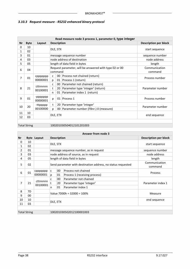
3.10.3 Request measure - RS232 enhanced binary protocol
Read measure node 3 process 1, parameter 0, type integer Nr Byte Layout Description Description per block 0 10
DLE, STX start sequence 1 02 3 01 message sequence number sequence number 4 03 node address of destination node address 5 05 length of data field in bytes length
6 04 Request parameter, will be answered with type 02 or 00 command
Communication command
7 01 cppppppp 00000001
c 00 Process not chained (return) Process number
p 01 Process 1 (return)
8 21 cttnnnnn 00100001
c 00 Parameter not chained (return) Parameter number t 20 Parameter type ‘integer’ (return)
n 01 Parameter index 1 (return)
9 01 -ppppppp 00000001 p 01 Process 1 Process number
10 20 -ttppppp 00100000
t 20 Parameter type ‘integer’ Parameter number
p 00 Parameter number (FBnr.) 0 (measure) 11 10
DLE, ETX end sequence 12 03
Total String 100201030504012101201003
Answer from node 3 Nr Byte Layout Description Description per block
0 10 DLE, STX start sequence
1 02 2 01 message sequence number, as in request sequence number 3 03 node address of source, as in request node address 4 05 length of data field in bytes length
5 02 Send parameter with destination address, no status requested Communication command
6 01 cppppppp 00000001
c 00 Process not chained Process
p 01 Process 1 (receiving process)
7 21 cttnnnnn 00100001
c 00 Parameter not chained Parameter index 1 t 20 Parameter type ‘integer’
n 01 Parameter index 1 8 7D
Value 7D00h = 32000 = 100% Measure 9 00
10 10 DLE, ETX
end sequence 11 03
Total String 100201030502012100001003
BRONKHORST®
Page 39 RS232 interface 9.17.027
3.10.4 Collection of RS232 enhanced binary examples
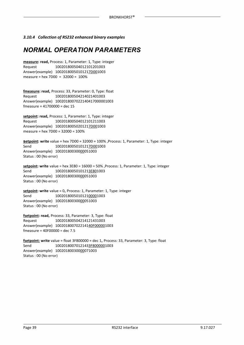
NORMAL OPERATION PARAMETERS measure: read, Process: 1, Parameter: 1, Type: integer Request 100201800504012101201003 Answer(example) 10020180050101217D001003 measure = hex 7D00 = 32000 = 100% fmeasure: read, Process: 33, Parameter: 0, Type: float Request 100201800504214021401003 Answer(example) 1002018007022140417000001003 fmeasure = 41700000 = dec 15 setpoint: read, Process: 1, Parameter: 1, Type: integer Request 100201800504012101211003 Answer(example) 10020180050201217D001003 measure = hex 7D00 = 32000 = 100% setpoint: write value = hex 7D00 = 32000 = 100% ,Process: 1, Parameter: 1, Type: integer Send 10020180050101217D001003 Answer(example) 10020180030000051003 Status : 00 (No error) setpoint: write value = hex 3E80 = 16000 = 50% ,Process: 1, Parameter: 1, Type: integer Send 10020180050101213E801003 Answer(example) 10020180030000051003 Status : 00 (No error) setpoint: write value = 0, Process: 1, Parameter: 1, Type: integer Send 100201800501012100001003 Answer(example) 10020180030000051003 Status : 00 (No error) fsetpoint: read, Process: 33, Parameter: 3, Type: float Request 100201800504214121431003 Answer(example) 100201800702214140F000001003 fmeasure = 40F00000 = dec 7.5 fsetpoint: write value = float 3F800000 = dec 1, Process: 33, Parameter: 3, Type: float Send 10020180070121433F8000001003 Answer(example) 10020180030000071003 Status : 00 (No error)
BRONKHORST®
Page 40 RS232 interface 9.17.027
3.10.5 Example chained parameters - RS232 enhanced binary protocol
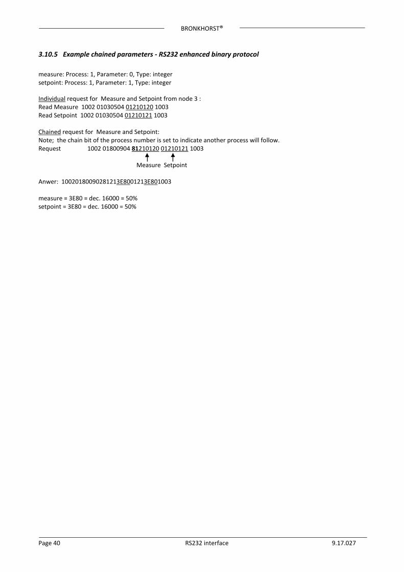
measure: Process: 1, Parameter: 0, Type: integer setpoint: Process: 1, Parameter: 1, Type: integer Individual request for Measure and Setpoint from node 3 : Read Measure 1002 01030504 01210120 1003 Read Setpoint 1002 01030504 01210121 1003 Chained request for Measure and Setpoint: Note; the chain bit of the process number is set to indicate another process will follow. Request 1002 01800904 81210120 01210121 1003 Measure Setpoint Anwer: 10020180090281213E8001213E801003 measure = 3E80 = dec. 16000 = 50% setpoint = 3E80 = dec. 16000 = 50%
BRONKHORST®
Page 41 RS232 interface 9.17.027
4 DUAL INTERFACE OPERATION When operating a controller (reading measured value and sending setpoint) for proper operation it is important that the controller gets its setpoint from the right source. Setpoints may come from different sources: analog input, field bus interface or RS232 or may be overruled by close valve or open valve (purge) commands. Therefore it is important to know what the setpoint source of the controller is. This can be set by means of parameter control mode (process 1, parameter 4). In some cases it is possible that the setpoints may come from 2 sources at the same time. The last send setpoint will be valid and send to the controller. This is the case in control mode = 0, when setpoints may come through any field bus interface or RS232. However, there could be situations where control over the instrument seems impossible. This is the case when the instrument comes into a safe-state e.g. when field bus communication is disturbed or disconnected. Valve will be forced to a safe state automatically: closed (NC) or fully open (NO). In case you want to get control back via RS232 operation, you have to change the control mode. When control mode gets value 18, safe state will be overruled and sending setpoints via RS232 interface will have effect on the controller again.
See also document nr. 9.17.023 for more detailed description about digital instrument parameters and their behaviour. http://www.bronkhorst.com/en/downloads/instruction_manuals/
BRONKHORST®
Page 42 RS232 interface 9.17.027
5 PARAMETER INFORMATION FLOW-BUS is used for parameter value exchange between instruments and operation modules (keyboard or PC-interface). Parameter information consists of several properties for behaviour within the FLOW-BUS system. In the ‘parameter properties’ table you will find a list of parameters and their properties. In the ‘parameter values’ table, the values are described more detailed. This list consists mostly of parameters for mode settings.
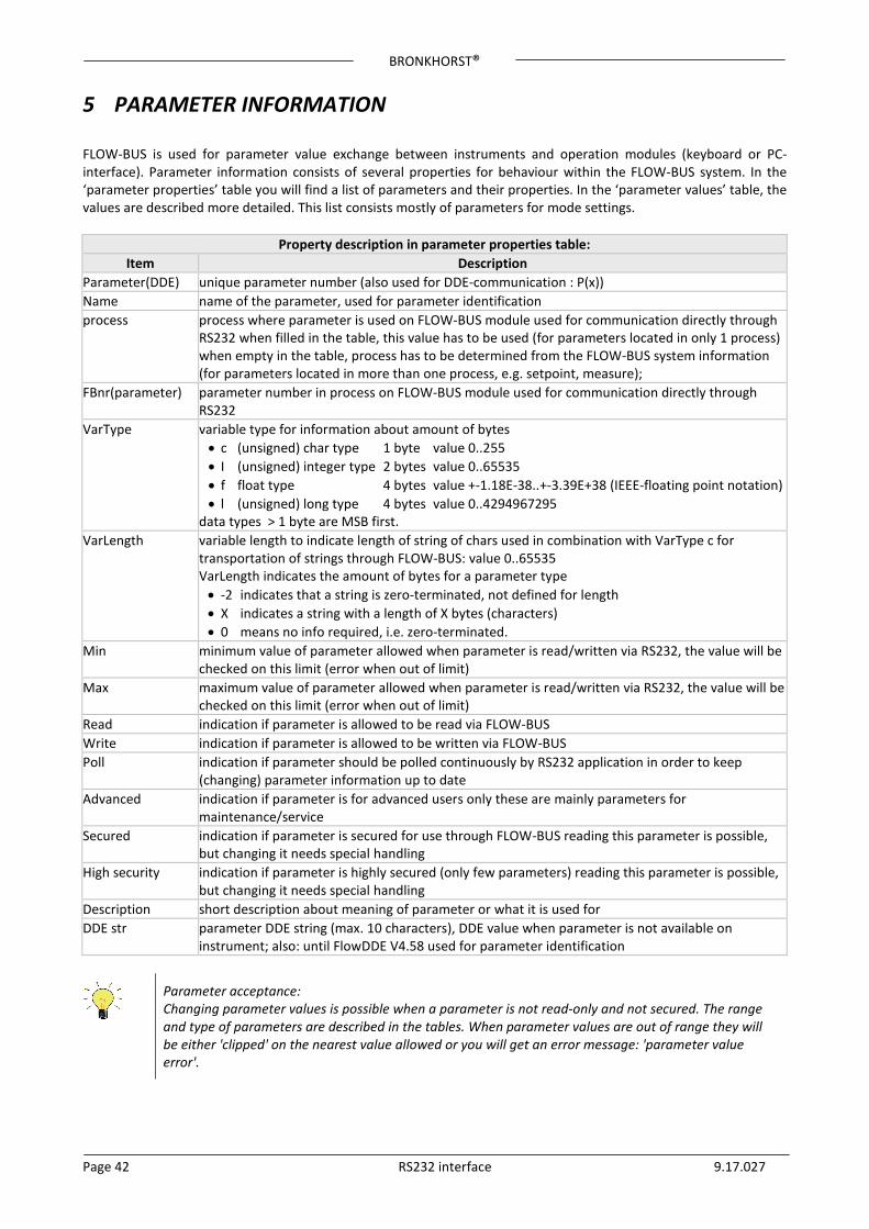
Property description in parameter properties table: Item Description
Parameter(DDE) unique parameter number (also used for DDE-communication : P(x)) Name name of the parameter, used for parameter identification process process where parameter is used on FLOW-BUS module used for communication directly through
RS232 when filled in the table, this value has to be used (for parameters located in only 1 process) when empty in the table, process has to be determined from the FLOW-BUS system information (for parameters located in more than one process, e.g. setpoint, measure);
FBnr(parameter) parameter number in process on FLOW-BUS module used for communication directly through RS232
VarType variable type for information about amount of bytes • c (unsigned) char type 1 byte value 0..255 • I (unsigned) integer type 2 bytes value 0..65535 • f float type 4 bytes value +-1.18E-38..+-3.39E+38 (IEEE-floating point notation) • l (unsigned) long type 4 bytes value 0..4294967295
data types > 1 byte are MSB first. VarLength variable length to indicate length of string of chars used in combination with VarType c for
transportation of strings through FLOW-BUS: value 0..65535 VarLength indicates the amount of bytes for a parameter type
• -2 indicates that a string is zero-terminated, not defined for length • X indicates a string with a length of X bytes (characters) • 0 means no info required, i.e. zero-terminated.
Min minimum value of parameter allowed when parameter is read/written via RS232, the value will be checked on this limit (error when out of limit)
Max maximum value of parameter allowed when parameter is read/written via RS232, the value will be checked on this limit (error when out of limit)
Read indication if parameter is allowed to be read via FLOW-BUS Write indication if parameter is allowed to be written via FLOW-BUS Poll indication if parameter should be polled continuously by RS232 application in order to keep
(changing) parameter information up to date Advanced indication if parameter is for advanced users only these are mainly parameters for
maintenance/service Secured indication if parameter is secured for use through FLOW-BUS reading this parameter is possible,
but changing it needs special handling High security indication if parameter is highly secured (only few parameters) reading this parameter is possible,
but changing it needs special handling Description short description about meaning of parameter or what it is used for DDE str parameter DDE string (max. 10 characters), DDE value when parameter is not available on
instrument; also: until FlowDDE V4.58 used for parameter identification
Parameter acceptance: Changing parameter values is possible when a parameter is not read-only and not secured. The range and type of parameters are described in the tables. When parameter values are out of range they will be either 'clipped' on the nearest value allowed or you will get an error message: 'parameter value error'.
BRONKHORST®
Page 43 RS232 interface 9.17.027
(FlowDDE) Parameter numbers: All parameter information is referenced to the parameter number. This is a unique number for a parameter to avoid redundancy. These numbers are needed for DDE communication only. For communication with FLOW-BUS through other ways than DDE: directly via RS232 ASCII-strings or via C-libraries (DOS or Windows), use the parameter numbers for the FLOW-BUS modules (in column FBnr of table Parameter properties). Now you will always have to know the node-address of the instrument on the FLOW-BUS, the process number on the instrument and the parameter number on the instrument. Process nr could be read from the table or has to be determined, when nothing is filled in. In most cases process number will be 1. Node-address should be determined also. This is the node-address of the instrument on the FLOW-BUS. Newer RS232 protocols on Multibus instruments accept node = 128. When sending messages to this node address, the message will be always accepted, unregarding the node address of the instrument on the bus.
It is important to know that not all parameters are available on all FLOW-BUS/Multibus devices. For more details about parameters and their use see also document nr. 9.17.023 for description of digital instruments. If you have the program FlowDDE, you can also get an overview of which parameters are available on which devices.
APPENDIX 1 AND 2 WILL GIVE INFORMATION ABOUT PARAMETERS, THEIR PROPERTIES AND THEIR POSSIBLE VALUES.
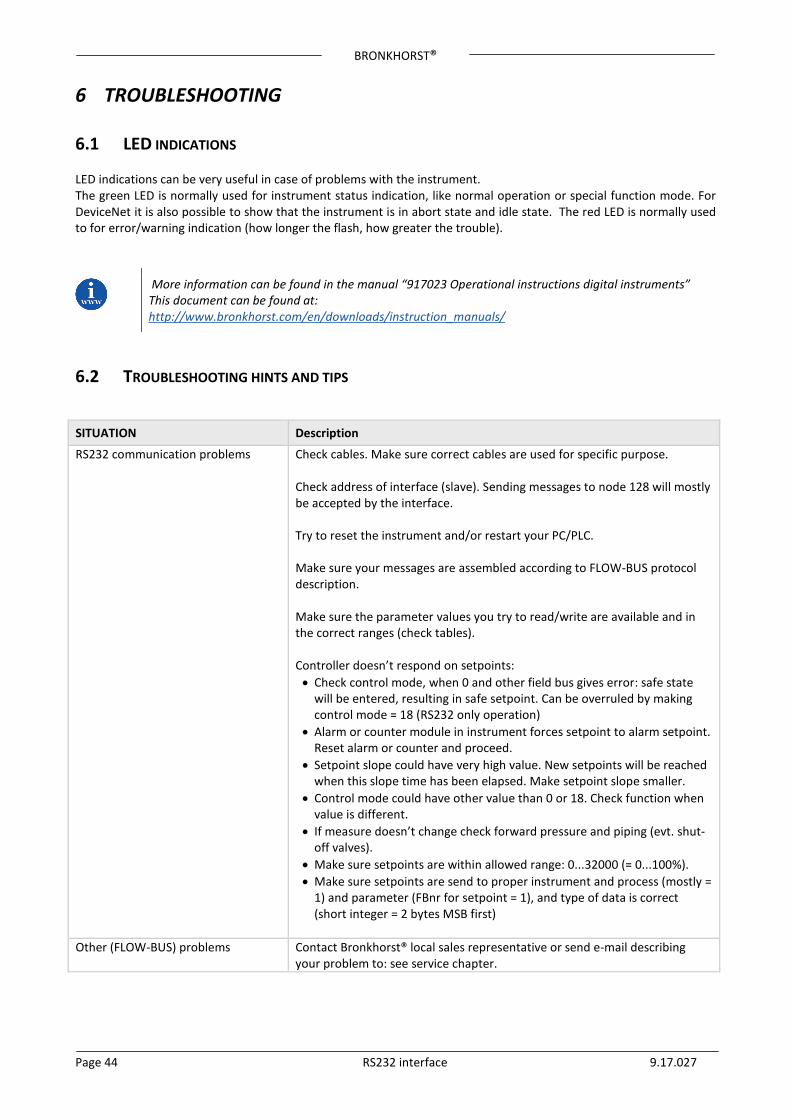
BRONKHORST®
Page 44 RS232 interface 9.17.027
6 TROUBLESHOOTING
6.1 LED INDICATIONS LED indications can be very useful in case of problems with the instrument. The green LED is normally used for instrument status indication, like normal operation or special function mode. For DeviceNet it is also possible to show that the instrument is in abort state and idle state. The red LED is normally used to for error/warning indication (how longer the flash, how greater the trouble).
More information can be found in the manual “917023 Operational instructions digital instruments” This document can be found at: http://www.bronkhorst.com/en/downloads/instruction_manuals/
6.2 TROUBLESHOOTING HINTS AND TIPS
SITUATION Description
RS232 communication problems Check cables. Make sure correct cables are used for specific purpose. Check address of interface (slave). Sending messages to node 128 will mostly be accepted by the interface. Try to reset the instrument and/or restart your PC/PLC. Make sure your messages are assembled according to FLOW-BUS protocol description. Make sure the parameter values you try to read/write are available and in the correct ranges (check tables). Controller doesn’t respond on setpoints:
• Check control mode, when 0 and other field bus gives error: safe state will be entered, resulting in safe setpoint. Can be overruled by making control mode = 18 (RS232 only operation)
• Alarm or counter module in instrument forces setpoint to alarm setpoint. Reset alarm or counter and proceed.
• Setpoint slope could have very high value. New setpoints will be reached when this slope time has been elapsed. Make setpoint slope smaller.
• Control mode could have other value than 0 or 18. Check function when value is different.
• If measure doesn’t change check forward pressure and piping (evt. shut-off valves).
• Make sure setpoints are within allowed range: 0...32000 (= 0...100%). • Make sure setpoints are send to proper instrument and process (mostly =
1) and parameter (FBnr for setpoint = 1), and type of data is correct (short integer = 2 bytes MSB first)
Other (FLOW-BUS) problems Contact Bronkhorst® local sales representative or send e-mail describing
your problem to: see service chapter.

BRONKHORST®
Page 45 RS232 interface 9.17.027
7 SERVICE For current information on Bronkhorst® and service addresses please visit our website:
http://www.bronkhorst.com
Do you have any questions about our products? Our Sales Department will gladly assist you selecting the right product for your application. Contact sales by e-mail:
For after-sales questions, our Customer Service Department is available with help and guidance. To contact CSD by e-mail:
No matter the time zone, our experts within the Support Group are available to answer your request immediately or ensure appropriate further action. Our experts can be reached at:
+31 859 02 18 66
BRONKHORST®
Page 46 RS232 interface 9.17.027
8 APPENDIX
8.1 PARAMETER VALUES TABLE See Below
8.2 PARAMETER PROPERTIES TABLE See Below
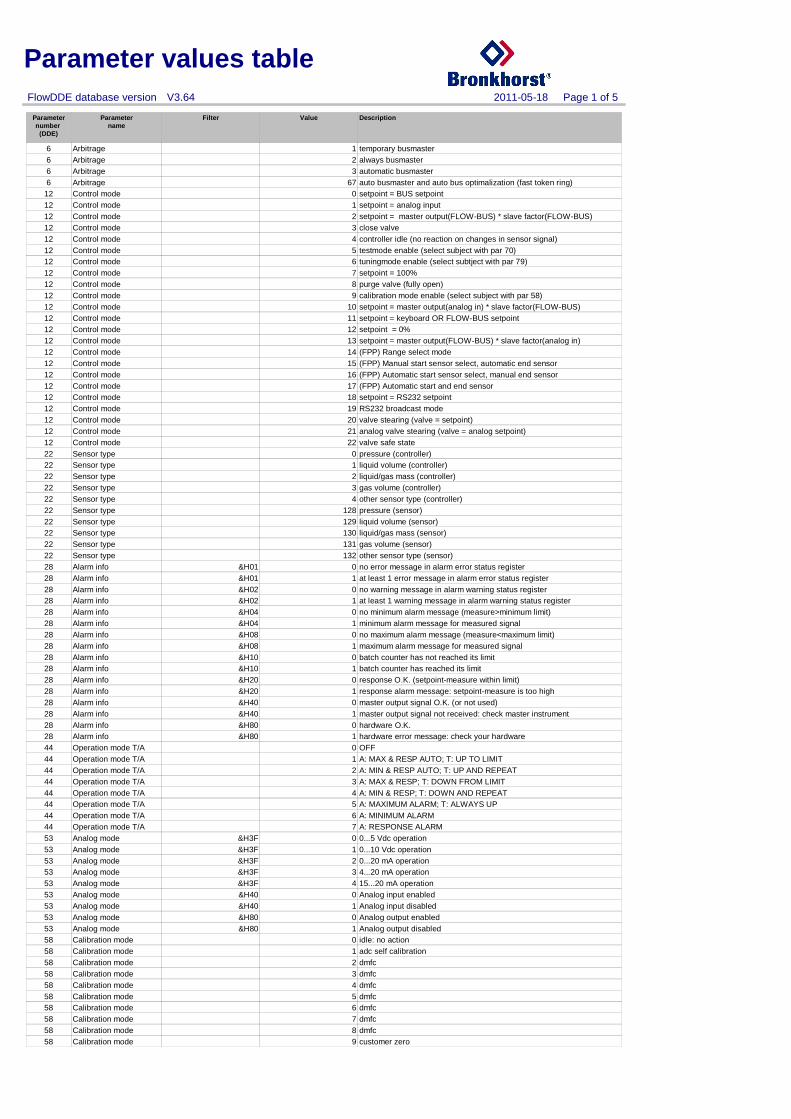
Parameter values table
Parameternumber
(DDE)
Parametername
Filter Value Description
2011-05-18 Page 1 of 5 FlowDDE database version V3.64
6 Arbitrage temporary busmaster16 Arbitrage always busmaster26 Arbitrage automatic busmaster36 Arbitrage auto busmaster and auto bus optimalization (fast token ring)67
12 Control mode setpoint = BUS setpoint012 Control mode setpoint = analog input112 Control mode setpoint = master output(FLOW-BUS) * slave factor(FLOW-BUS)212 Control mode close valve312 Control mode controller idle (no reaction on changes in sensor signal)412 Control mode testmode enable (select subject with par 70)512 Control mode tuningmode enable (select subtject with par 79)612 Control mode setpoint = 100%712 Control mode purge valve (fully open)812 Control mode calibration mode enable (select subject with par 58)912 Control mode setpoint = master output(analog in) * slave factor(FLOW-BUS)1012 Control mode setpoint = keyboard OR FLOW-BUS setpoint1112 Control mode setpoint = 0%1212 Control mode setpoint = master output(FLOW-BUS) * slave factor(analog in)1312 Control mode (FPP) Range select mode1412 Control mode (FPP) Manual start sensor select, automatic end sensor1512 Control mode (FPP) Automatic start sensor select, manual end sensor1612 Control mode (FPP) Automatic start and end sensor1712 Control mode setpoint = RS232 setpoint1812 Control mode RS232 broadcast mode1912 Control mode valve stearing (valve = setpoint)2012 Control mode analog valve stearing (valve = analog setpoint)2112 Control mode valve safe state2222 Sensor type pressure (controller)022 Sensor type liquid volume (controller)122 Sensor type liquid/gas mass (controller)222 Sensor type gas volume (controller)322 Sensor type other sensor type (controller)422 Sensor type pressure (sensor)12822 Sensor type liquid volume (sensor)12922 Sensor type liquid/gas mass (sensor)13022 Sensor type gas volume (sensor)13122 Sensor type other sensor type (sensor)13228 Alarm info &H01 no error message in alarm error status register028 Alarm info &H01 at least 1 error message in alarm error status register128 Alarm info &H02 no warning message in alarm warning status register028 Alarm info &H02 at least 1 warning message in alarm warning status register128 Alarm info &H04 no minimum alarm message (measure>minimum limit)028 Alarm info &H04 minimum alarm message for measured signal128 Alarm info &H08 no maximum alarm message (measure<maximum limit)028 Alarm info &H08 maximum alarm message for measured signal128 Alarm info &H10 batch counter has not reached its limit028 Alarm info &H10 batch counter has reached its limit128 Alarm info &H20 response O.K. (setpoint-measure within limit)028 Alarm info &H20 response alarm message: setpoint-measure is too high128 Alarm info &H40 master output signal O.K. (or not used)028 Alarm info &H40 master output signal not received: check master instrument128 Alarm info &H80 hardware O.K.028 Alarm info &H80 hardware error message: check your hardware144 Operation mode T/A OFF044 Operation mode T/A A: MAX & RESP AUTO; T: UP TO LIMIT144 Operation mode T/A A: MIN & RESP AUTO; T: UP AND REPEAT244 Operation mode T/A A: MAX & RESP; T: DOWN FROM LIMIT344 Operation mode T/A A: MIN & RESP; T: DOWN AND REPEAT444 Operation mode T/A A: MAXIMUM ALARM; T: ALWAYS UP544 Operation mode T/A A: MINIMUM ALARM644 Operation mode T/A A: RESPONSE ALARM753 Analog mode &H3F 0...5 Vdc operation053 Analog mode &H3F 0...10 Vdc operation153 Analog mode &H3F 0...20 mA operation253 Analog mode &H3F 4...20 mA operation353 Analog mode &H3F 15...20 mA operation453 Analog mode &H40 Analog input enabled053 Analog mode &H40 Analog input disabled153 Analog mode &H80 Analog output enabled053 Analog mode &H80 Analog output disabled158 Calibration mode idle: no action058 Calibration mode adc self calibration158 Calibration mode dmfc258 Calibration mode dmfc358 Calibration mode dmfc458 Calibration mode dmfc558 Calibration mode dmfc658 Calibration mode dmfc758 Calibration mode dmfc858 Calibration mode customer zero9
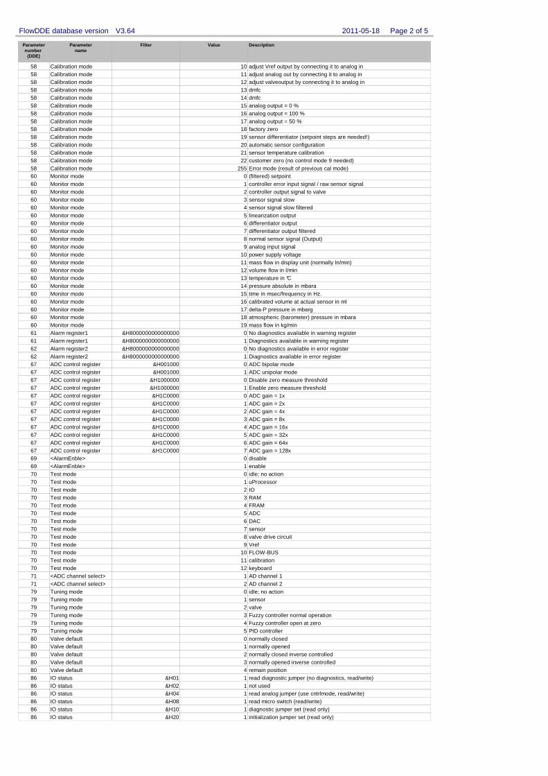
Parameternumber
(DDE)
Parametername
Filter Value Description
2011-05-18 Page 2 of 5 FlowDDE database version V3.64
58 Calibration mode adjust Vref output by connecting it to analog in1058 Calibration mode adjust analog out by connecting it to analog in1158 Calibration mode adjust valveoutput by connecting it to analog in1258 Calibration mode dmfc1358 Calibration mode dmfc1458 Calibration mode analog output = 0 %1558 Calibration mode analog output = 100 %1658 Calibration mode analog output = 50 %1758 Calibration mode factory zero1858 Calibration mode sensor differentiator (setpoint steps are needed!)1958 Calibration mode automatic sensor configuration2058 Calibration mode sensor temperature calibration2158 Calibration mode customer zero (no control mode 9 needed)2258 Calibration mode Error mode (result of previous cal mode)25560 Monitor mode (filtered) setpoint060 Monitor mode controller error input signal / raw sensor signal160 Monitor mode controller output signal to valve260 Monitor mode sensor signal slow360 Monitor mode sensor signal slow filtered460 Monitor mode linearization output560 Monitor mode differentiator output660 Monitor mode differentiator output filtered760 Monitor mode normal sensor signal (Output)860 Monitor mode analog input signal960 Monitor mode power supply voltage1060 Monitor mode mass flow in display unit (normally ln/min)1160 Monitor mode volume flow in l/min1260 Monitor mode temperature in °C1360 Monitor mode pressure absolute in mbara1460 Monitor mode time in msec/frequency in Hz.1560 Monitor mode calibrated volume at actual sensor in ml1660 Monitor mode delta-P pressure in mbarg1760 Monitor mode atmospheric (barometer) pressure in mbara1860 Monitor mode mass flow in kg/min1961 Alarm register1 &H8000000000000000 No diagnostics available in warning register061 Alarm register1 &H8000000000000000 Diagnostics available in warning register162 Alarm register2 &H8000000000000000 No diagnostics available in error register062 Alarm register2 &H8000000000000000 Diagnostics available in error register167 ADC control register &H001000 ADC bipolar mode067 ADC control register &H001000 ADC unipolar mode167 ADC control register &H1000000 Disable zero measure threshold067 ADC control register &H1000000 Enable zero measure threshold167 ADC control register &H1C0000 ADC gain = 1x067 ADC control register &H1C0000 ADC gain = 2x167 ADC control register &H1C0000 ADC gain = 4x267 ADC control register &H1C0000 ADC gain = 8x367 ADC control register &H1C0000 ADC gain = 16x467 ADC control register &H1C0000 ADC gain = 32x567 ADC control register &H1C0000 ADC gain = 64x667 ADC control register &H1C0000 ADC gain = 128x769 <AlarmEnble> disable069 <AlarmEnble> enable170 Test mode idle; no action070 Test mode uProcessor170 Test mode IO270 Test mode RAM370 Test mode FRAM470 Test mode ADC570 Test mode DAC670 Test mode sensor770 Test mode valve drive circuit870 Test mode Vref970 Test mode FLOW-BUS1070 Test mode calibration1170 Test mode keyboard1271 <ADC channel select> AD channel 1171 <ADC channel select> AD channel 2279 Tuning mode idle; no action079 Tuning mode sensor179 Tuning mode valve279 Tuning mode Fuzzy controller normal operation379 Tuning mode Fuzzy controller open at zero479 Tuning mode PID controller580 Valve default normally closed080 Valve default normally opened180 Valve default normally closed inverse controlled280 Valve default normally opened inverse controlled380 Valve default remain position486 IO status &H01 read diagnostic jumper (no diagnostics, read/write)186 IO status &H02 not used186 IO status &H04 read analog jumper (use cntrlmode, read/write)186 IO status &H08 read micro switch (read/write)186 IO status &H10 diagnostic jumper set (read only)186 IO status &H20 initialization jumper set (read only)1

Parameternumber
(DDE)
Parametername
Filter Value Description
2011-05-18 Page 3 of 5 FlowDDE database version V3.64
86 IO status &H40 analog jumper set (read only)186 IO status &H80 micro switch pressed (read only)1
106 Pressure sensor type delta-P 0..5" W.C.0106 Pressure sensor type delta-P 0...10" W.C.1106 Pressure sensor type absolute pressure 800-1200 mbar2106 Pressure sensor type absolute pressure 800-1100 mbar3106 Pressure sensor type delta-P -5...0 "W.C.4106 Pressure sensor type delta-P -10...0 "W.C.5106 Pressure sensor type delta-P -10...+10 "W.C.6106 Pressure sensor type delta-P 0...1 PSI7106 Pressure sensor type delta-P -1...0 PSI8106 Pressure sensor type absolute pressure 0-10 bar10114 Reset no reset0114 Reset reset counter value (no mode change) or common reset1114 Reset reset alarm2114 Reset restart batch counter3114 Reset reset counter value (counter off)4114 Reset Reset module (soft reset)5118 Alarm mode off0118 Alarm mode alarm on absolute limits1118 Alarm mode alarm on limits related to setpoint (response alarm)2118 Alarm mode alarm when instrument powers-up (eg. after power-down)3119 Alarm output mode no relais activity at alarm0119 Alarm output mode relais pulses until reset1119 Alarm output mode relais activated until reset2120 Alarm setpoint mode no setpoint change at alarm0120 Alarm setpoint mode new/safe setpoint at alarm enabled (set at par 121)1125 Counter output mode no relais activity at batch limit0125 Counter output mode relais pulses after reaching batch limit until reset1125 Counter output mode relais activated after reaching batch limit until reset2126 Counter setpoint mode setpoint change at batch limit disabled0126 Counter setpoint mode setpoint change at batch limit enabled1130 Counter mode off0130 Counter mode counting upwards continuously1130 Counter mode counting up to limit (batchcounter)2147 Range select calibration ready/stop0147 Range select run calibration until stopsensor 1/select range 11147 Range select run calibration until stopsensor 2/select range 22147 Range select run calibration until stopsensor 3/select range 33147 Range select run calibration until stopsensor 4/select range 44147 Range select run calibration and select range 55147 Range select run calibration with automatic range selection9147 Range select run until stopsensor 1 until 3 values between limit19147 Range select run until stopsensor 2 until 3 values between limit29147 Range select run until stopsensor 3 until 3 values between limit39147 Range select run until stopsensor 4 until 3 values between limit49147 Range select run and select range 5 until 3 values between limit59147 Range select run with auto-select + 3 values between limit99156 Reset alarm enable no reset possible0156 Reset alarm enable reset: keyboard1156 Reset alarm enable reset: external2156 Reset alarm enable reset: keyboard or external3156 Reset alarm enable reset: FLOW-BUS4156 Reset alarm enable reset: FLOW-BUS or keyboard5156 Reset alarm enable reset: FLOW-BUS or external6156 Reset alarm enable reset: FLOW-BUS or keyboard or external7156 Reset alarm enable reset: automatic8156 Reset alarm enable reset: automatic or keyboard9156 Reset alarm enable reset: automatic or external10156 Reset alarm enable reset: automatic or keyboard or external11156 Reset alarm enable reset: automatic or FLOW-BUS12156 Reset alarm enable reset: automatic or FLOW-BUS or keyboard13156 Reset alarm enable reset: automatic or FLOW-BUS or external14156 Reset alarm enable reset: automatic or FLOW-BUS or keyboard or external15157 Reset counter enable no reset possible0157 Reset counter enable reset: keyboard1157 Reset counter enable reset: external2157 Reset counter enable reset: keyboard or external3157 Reset counter enable reset: FLOW-BUS4157 Reset counter enable reset: FLOW-BUS or keyboard5157 Reset counter enable reset: FLOW-BUS or external6157 Reset counter enable reset: FLOW-BUS or keyboard or external7157 Reset counter enable reset: automatic8157 Reset counter enable reset: automatic or keyboard9157 Reset counter enable reset: automatic or external10157 Reset counter enable reset: automatic or keyboard or external11157 Reset counter enable reset: automatic or FLOW-BUS12157 Reset counter enable reset: automatic or FLOW-BUS or keyboard13157 Reset counter enable reset: automatic or FLOW-BUS or external14157 Reset counter enable reset: automatic or FLOW-BUS or keyboard or external15166 Controller features &H01 valve in normal position after startup0166 Controller features &H01 valve in safe position after startup1166 Controller features &H02 open from zero with PID output to valve0166 Controller features &H02 open from zero with ramp output to valve1

Parameternumber
(DDE)
Parametername
Filter Value Description
2011-05-18 Page 4 of 5 FlowDDE database version V3.64
166 Controller features &H04 fixed monitor output signal0166 Controller features &H04 monitor output changed at setpoint steps1166 Controller features &H08 voltage drift compensation for valve output turned on0166 Controller features &H08 voltage drift compensation for valve output turned off1166 Controller features &H10 auto slope disabled0166 Controller features &H10 auto slope enabled for pilot valves1166 Controller features &H20 automatic correction for valve open turned on0166 Controller features &H20 automatic correction for valve open turned off1166 Controller features &H40 controller special mode (valve output steps) turned off0166 Controller features &H40 controller special mode (valve output steps) turned on1166 Controller features &H80 valve overshoot protection turned off0166 Controller features &H80 valve overshoot protection turned on1175 Identification number UFO?: Unidentified FLOW-BUS Object0175 Identification number RS232/FLOW-BUS interface1175 Identification number PC(ISA) interface2175 Identification number ADDA4 (4 channels)3175 Identification number R/C-module, 32 channels4175 Identification number T/A-module5175 Identification number ADDA1: 1 channel ADDA converter module6175 Identification number DMFC: digital mass flow controller7175 Identification number DMFM: digital mass flow meter8175 Identification number DEPC: digital electronic pressure controller9175 Identification number DEPM: digital electronic pressure meter10175 Identification number ACT: single actuator11175 Identification number DLFC: digital liquid flow controller12175 Identification number DLFM: digital liquid flow meter13175 Identification number DSCM-A: digital single channel module for analog instruments14175 Identification number DSCM-D: digital single channel module for digital instr.15175 Identification number FRM: FLOW-BUS rotor meter (calibration-instrument)16175 Identification number FTM: FLOW-BUS turbine meter (calibration-instrument)17175 Identification number FPP: FLOW-BUS piston prover/tube (calibration-instrument)18175 Identification number F/A-module: special version of T/A-module19175 Identification number DSCM-E: evaporator controller module (single channel)20175 Identification number DSCM-C: digital single channel module for calibrators21175 Identification number DDCM-A: digital dual channel module for analog instruments22175 Identification number DMCM-D: digital multi channel module for digital instruments23175 Identification number Profibus-DP/FLOW-BUS interface module24175 Identification number FLOW-BUS Coriolis Meter25175 Identification number FBI: FLOW-BUS Balance Interface26175 Identification number CORIFC: CoriFlow Controller27175 Identification number CORIFM: CoriFlow Meter28175 Identification number FICC: FLOW-BUS Interface Climate Control29175 Identification number IFI: Instrument FLOW-BUS Interface30175 Identification number KFI: Keithley FLOW-BUS Interface31175 Identification number FSI: FLOW-BUS Switch Interface32175 Identification number MSCI: Multi-Sensor/Confroller Interface33175 Identification number APP-D: Active Piston Prover34175 Identification number LFI: Leaktester FLOW-BUS Interface35185 Device function Unknown0185 Device function Interface1185 Device function ADDA2185 Device function Operator3185 Device function Supervisor (totalizer/alarm)4185 Device function Controller5185 Device function Meter6185 Device function Special7185 Device function (Protocol) converter8197 Calibrations options &H01 Automatic capacity setting for optimal resolution0197 Calibrations options &H01 Manual capacity setting for optimal resolution1197 Calibrations options &H02 Barometer value input via parameter 107: BaroPress0197 Calibrations options &H02 Barometer is master; input automatically from master1200 Interface configuration Configuration A: 14 ch. Standard parms. with network scan0200 Interface configuration Configuration B: 14 ch. Standard parms with fixed chan list1200 Interface configuration Configuration C: 7 ch. Extended parms with fixed chan list2200 Interface configuration Configuration D: 11 ch. Extended parms with network scan3208 Manufacturer status regi &H800000 No diagnostics available in manufacturer status register0208 Manufacturer status regi &H800000 Diagnostics available in manufacturer status register1209 Manufacturer warning re &H800000 No diagnostics available in manufacturer warning register0209 Manufacturer warning re &H800000 Diagnostics available in manufacturer warning register1210 Manufacturer error regis &H800000 No diagnostics available in manufacturer error register0210 Manufacturer error regis &H800000 Diagnostics available in manufacturer error register1212 Diagnostic mode Debug mode off0212 Diagnostic mode Debug mode on1213 Manufacturer status ena set status bit (range 0…127)0213 Manufacturer status ena set status bit (range 0…127)127213 Manufacturer status ena clear all status bits254213 Manufacturer status ena set all status bits255232 Valve mode voltage drive mode0232 Valve mode current drive mode1238 Fluidset properties &H01 Fluidset is disabled0238 Fluidset properties &H01 Fluidset is enabled1238 Fluidset properties &H02 Fluidset is not set by Bronkhorst High-Tech0238 Fluidset properties &H02 Fluidset is set by Bronkhorst High-Tech2238 Fluidset properties &H04 Fluidset is not calibrated on actual gas0
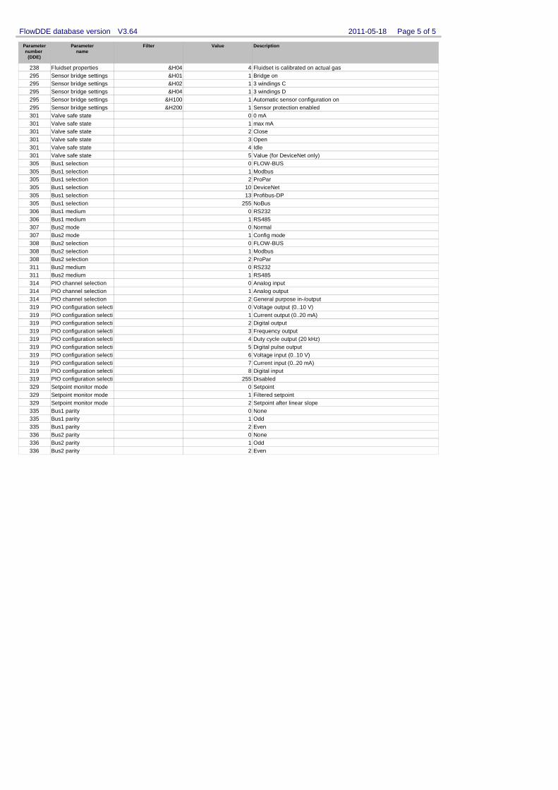
Parameternumber
(DDE)
Parametername
Filter Value Description
2011-05-18 Page 5 of 5 FlowDDE database version V3.64
238 Fluidset properties &H04 Fluidset is calibrated on actual gas4295 Sensor bridge settings &H01 Bridge on1295 Sensor bridge settings &H02 3 windings C1295 Sensor bridge settings &H04 3 windings D1295 Sensor bridge settings &H100 Automatic sensor configuration on1295 Sensor bridge settings &H200 Sensor protection enabled1301 Valve safe state 0 mA0301 Valve safe state max mA1301 Valve safe state Close2301 Valve safe state Open3301 Valve safe state Idle4301 Valve safe state Value (for DeviceNet only)5305 Bus1 selection FLOW-BUS0305 Bus1 selection Modbus1305 Bus1 selection ProPar2305 Bus1 selection DeviceNet10305 Bus1 selection Profibus-DP13305 Bus1 selection NoBus255306 Bus1 medium RS2320306 Bus1 medium RS4851307 Bus2 mode Normal0307 Bus2 mode Config mode1308 Bus2 selection FLOW-BUS0308 Bus2 selection Modbus1308 Bus2 selection ProPar2311 Bus2 medium RS2320311 Bus2 medium RS4851314 PIO channel selection Analog input0314 PIO channel selection Analog output1314 PIO channel selection General purpose in-/output2319 PIO configuration selecti Voltage output (0..10 V)0319 PIO configuration selecti Current output (0..20 mA)1319 PIO configuration selecti Digital output2319 PIO configuration selecti Frequency output3319 PIO configuration selecti Duty cycle output (20 kHz)4319 PIO configuration selecti Digital pulse output5319 PIO configuration selecti Voltage input (0..10 V)6319 PIO configuration selecti Current input (0..20 mA)7319 PIO configuration selecti Digital input8319 PIO configuration selecti Disabled255329 Setpoint monitor mode Setpoint0329 Setpoint monitor mode Filtered setpoint1329 Setpoint monitor mode Setpoint after linear slope2335 Bus1 parity None0335 Bus1 parity Odd1335 Bus1 parity Even2336 Bus2 parity None0336 Bus2 parity Odd1336 Bus2 parity Even2
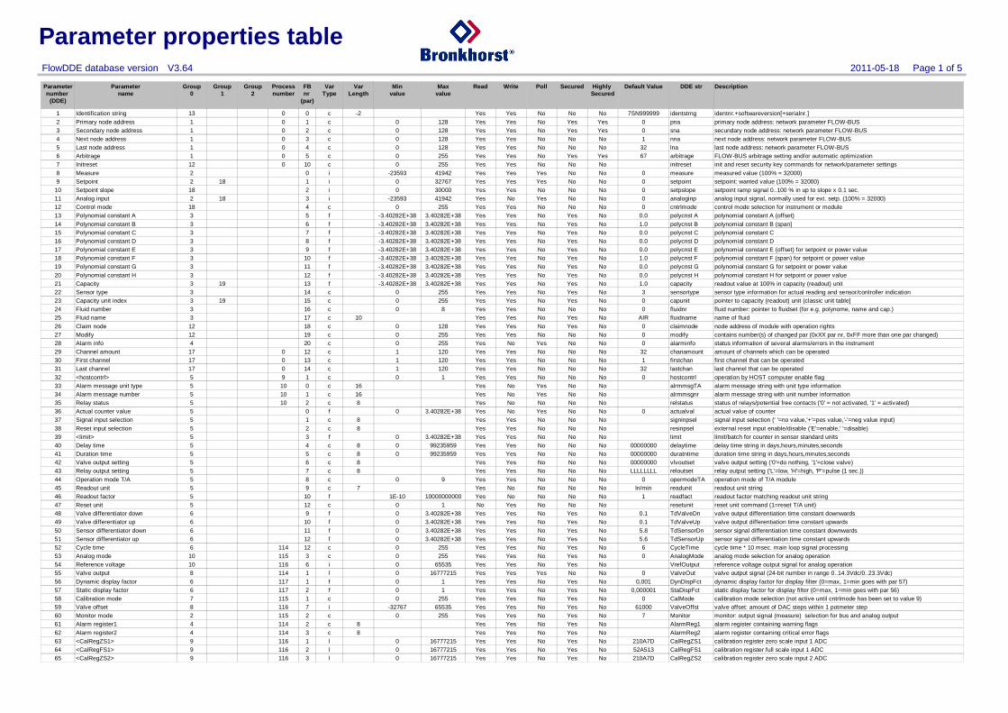
Parameter properties table
Parameternumber
(DDE)
Parametername
Group0
Group1
Group2
Processnumber
FBnr
(par)
VarType
VarLength
Minvalue
Maxvalue
Read Write Poll Secured Highly Secured
Default Value Description
2011-05-18 Page 1 of 5FlowDDE database version V3.64
DDE str
1 Identification string 13 0 0 c -2 Yes Yes No No No 7SN999999 identnr.+softwareversion[+serialnr.]identstrng2 Primary node address 1 0 1 c 0 128 Yes Yes No Yes Yes 0 primary node address: network parameter FLOW-BUSpna3 Secondary node address 1 0 2 c 0 128 Yes Yes No Yes Yes 0 secundary node address: network parameter FLOW-BUSsna4 Next node address 1 0 3 c 0 128 Yes Yes No No No 1 next node address: network parameter FLOW-BUSnna5 Last node address 1 0 4 c 0 128 Yes Yes No No No 32 last node address: network parameter FLOW-BUSlna6 Arbitrage 1 0 5 c 0 255 Yes Yes No Yes Yes 67 FLOW-BUS arbitrage setting and/or automatic optimizationarbitrage7 Initreset 12 0 10 c 0 255 Yes Yes No No No init and reset security key commands for network/parameter settingsinitreset8 Measure 2 0 i -23593 41942 Yes Yes Yes No No 0 measured value (100% = 32000)measure9 Setpoint 2 18 1 i 0 32767 Yes Yes Yes No No 0 setpoint: wanted value (100% = 32000)setpoint
10 Setpoint slope 18 2 i 0 30000 Yes Yes No No No 0 setpoint ramp signal 0..100 % in up to slope x 0.1 sec.setpslope11 Analog input 2 18 3 i -23593 41942 Yes No Yes No No 0 analog input signal, normally used for ext. setp. (100% = 32000)analoginp12 Control mode 18 4 c 0 255 Yes Yes No No No 0 control mode selection for instrument or modulecntrlmode13 Polynomial constant A 3 5 f -3.40282E+38 3.40282E+38 Yes Yes No Yes No 0.0 polynomial constant A (offset)polycnst A14 Polynomial constant B 3 6 f -3.40282E+38 3.40282E+38 Yes Yes No Yes No 1.0 polynomial constant B (span]polycnst B15 Polynomial constant C 3 7 f -3.40282E+38 3.40282E+38 Yes Yes No Yes No 0.0 polynomial constant Cpolycnst C16 Polynomial constant D 3 8 f -3.40282E+38 3.40282E+38 Yes Yes No Yes No 0.0 polynomial constant Dpolycnst D17 Polynomial constant E 3 9 f -3.40282E+38 3.40282E+38 Yes Yes No Yes No 0.0 polynomial constant E (offset) for setpoint or power valuepolycnst E18 Polynomial constant F 3 10 f -3.40282E+38 3.40282E+38 Yes Yes No Yes No 1.0 polynomial constant F (span) for setpoint or power valuepolycnst F19 Polynomial constant G 3 11 f -3.40282E+38 3.40282E+38 Yes Yes No Yes No 0.0 polynomial constant G for setpoint or power valuepolycnst G20 Polynomial constant H 3 12 f -3.40282E+38 3.40282E+38 Yes Yes No Yes No 0.0 polynomial constant H for setpoint or power valuepolycnst H21 Capacity 3 19 13 f -3.40282E+38 3.40282E+38 Yes Yes No Yes No 1.0 readout value at 100% in capacity (readout) unitcapacity22 Sensor type 3 14 c 0 255 Yes Yes No Yes No 3 sensor type information for actual reading and sensor/controller indicationsensortype23 Capacity unit index 3 19 15 c 0 255 Yes Yes No Yes No 0 pointer to capacity (readout) unit (classic unit table]capunit24 Fluid number 3 16 c 0 8 Yes Yes No No No 0 fluid number: pointer to fluidset (for e.g. polynome, name and cap.)fluidnr25 Fluid name 3 17 c 10 Yes Yes No Yes No AIR name of fluidfluidname26 Claim node 12 18 c 0 128 Yes Yes No Yes No 0 node address of module with operation rightsclaimnode27 Modify 12 19 c 0 255 Yes Yes No No No 0 contains number(s) of changed par (0xXX par nr, 0xFF more than one par changed)modify28 Alarm info 4 20 c 0 255 Yes No Yes No No 0 status information of several alarms/errors in the instrumentalarminfo29 Channel amount 17 0 12 c 1 120 Yes Yes No No No 32 amount of channels which can be operatedchanamount30 First channel 17 0 13 c 1 120 Yes Yes No No No 1 first channel that can be operatedfirstchan31 Last channel 17 0 14 c 1 120 Yes Yes No No No 32 last channel that can be operatedlastchan32 <hostcontrl> 5 9 1 c 0 1 Yes Yes No No No 0 operation by HOST computer enable flaghostcontrl33 Alarm message unit type 5 10 0 c 16 Yes No Yes No No alarm message string with unit type informationalrmmsgTA34 Alarm message number 5 10 1 c 16 Yes No Yes No No alarm message string with unit number informationalrmmsgnr35 Relay status 5 10 2 c 8 Yes No No No No status of relays/potential free contacts ('0' = not activated, '1' = activated)relstatus36 Actual counter value 5 0 f 0 3.40282E+38 Yes No Yes No No 0 actual value of counteractualval37 Signal input selection 5 1 c 8 Yes Yes No No No signal input selection (' '=no value,'+'=pos value,'-'=neg value input)signinpsel38 Reset input selection 5 2 c 8 Yes Yes No No No external reset input enable/disable ('E'=enable,' '=disable)resinpsel39 <limit> 5 3 f 0 3.40282E+38 Yes Yes No No No limit/batch for counter in sensor standard unitslimit40 Delay time 5 4 c 8 0 99235959 Yes Yes No No No 00000000 delay time string in days,hours,minutes,secondsdelaytime41 Duration time 5 5 c 8 0 99235959 Yes Yes No No No 00000000 duration time string in days,hours,minutes,secondsduratntime42 Valve output setting 5 6 c 8 Yes Yes No No No 00000000 valve output setting ('0'=do nothing, '1'=close valve)vlvoutset43 Relay output setting 5 7 c 8 Yes Yes No No No LLLLLLLL relay output setting ('L'=low, 'H'=high, 'P'=pulse (1 sec.))reloutset44 Operation mode T/A 5 8 c 0 9 Yes Yes No No No 0 operation mode of T/A moduleopermodeTA45 Readout unit 5 9 c 7 Yes No No No No ln/min readout unit stringreadunit46 Readout factor 5 10 f 1E-10 10000000000 Yes No No No No 1 readout factor matching readout unit stringreadfact47 Reset unit 5 12 c 0 1 No Yes No No No reset unit command (1=reset T/A unit)resetunit48 Valve differentiator down 6 9 f 0 3.40282E+38 Yes Yes No Yes No 0.1 valve output differentiation time constant downwardsTdValveDn49 Valve differentiator up 6 10 f 0 3.40282E+38 Yes Yes No Yes No 0.1 valve output differentiation time constant upwardsTdValveUp50 Sensor differentiator down 6 11 f 0 3.40282E+38 Yes Yes No Yes No 5.8 sensor signal differentiation time constant downwardsTdSensorDn51 Sensor differentiator up 6 12 f 0 3.40282E+38 Yes Yes No Yes No 5.6 sensor signal differentiation time constant upwardsTdSensorUp52 Cycle time 6 114 12 c 0 255 Yes Yes No Yes No 6 cycle time * 10 msec. main loop signal processingCycleTime53 Analog mode 10 115 3 c 0 255 Yes Yes No Yes No 0 analog mode selection for analog operationAnalogMode54 Reference voltage 10 116 6 i 0 65535 Yes Yes No Yes No reference voltage output signal for analog operationVrefOutput55 Valve output 8 114 1 l 0 16777215 Yes Yes Yes No No 0 valve output signal (24-bit number in range 0..14.3Vdc/0..23.3Vdc)ValveOut56 Dynamic display factor 6 117 1 f 0 1 Yes Yes No Yes No 0,001 dynamic display factor for display filter (0=max, 1=min goes with par 57)DynDispFct57 Static display factor 6 117 2 f 0 1 Yes Yes No Yes No 0,000001 static display factor for display filter (0=max, 1=min goes with par 56)StaDispFct58 Calibration mode 7 115 1 c 0 255 Yes Yes No Yes No 0 calibration mode selection (not active until cntrlmode has been set to value 9)CalMode59 Valve offset 8 116 7 i -32767 65535 Yes Yes No Yes No 61000 valve offset: amount of DAC steps within 1 potmeter stepValveOffst60 Monitor mode 2 115 2 c 0 255 Yes Yes No Yes No 7 monitor: output signal (measure) selection for bus and analog outputMonitor61 Alarm register1 4 114 2 c 8 Yes Yes No Yes No alarm register containing warning flagsAlarmReg162 Alarm register2 4 114 3 c 8 Yes Yes No Yes No alarm register containing critical error flagsAlarmReg263 <CalRegZS1> 9 116 1 l 0 16777215 Yes Yes No Yes No 210A7D calibration register zero scale input 1 ADCCalRegZS164 <CalRegFS1> 9 116 2 l 0 16777215 Yes Yes No Yes No 52A513 calibration register full scale input 1 ADCCalRegFS165 <CalRegZS2> 9 116 3 l 0 16777215 Yes Yes No Yes No 210A7D calibration register zero scale input 2 ADCCalRegZS2
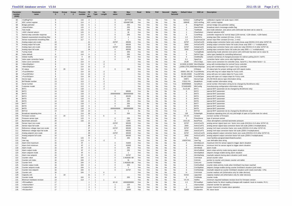
Parameternumber
(DDE)
Parametername
Group0
Group1
Group2
Processnumber
FBnr
(par)
VarType
VarLength
Minvalue
Maxvalue
Read Write Poll Secured Highly Secured
Default Value Description
2011-05-18 Page 2 of 5FlowDDE database version V3.64
DDE str
66 <CalRegFS2> 9 116 4 l 0 16777215 Yes Yes No Yes No 52A513 calibration register full scale input 2 ADCCalRegFS267 ADC control register 9 114 4 l 0 4294967295 Yes Yes No Yes No 18904E ADC control registerADCcntrReg68 Bridge potmeter 9 116 5 c 0 255 Yes Yes No Yes No 0 sensor bridge zero potmeter settingBridgePotm69 <AlarmEnble> 4 115 4 c 0 255 Yes Yes No Yes No 1 broadcast alarm messsage enable flagAlarmEnble70 Test mode 4 115 5 c 0 255 Yes Yes No Yes No 0 test mode selection (not active until cntrlmode has been set to value 5)TestMode71 <ADC channel select> 9 115 6 c 1 32 Yes Yes No Yes No 1 channel selection ADCChanSelect72 Normal step controller response 8 114 5 c 0 255 Yes Yes No Yes No 0 controller response for normal steps (128=normal, <128=slower, >128=faster)ContrResp73 Setpoint exponential smoothing filter 6 117 3 f 0 1 Yes Yes No Yes No 1.0 analog input filter constant (0=max, 1=min)ErrInFilCo74 Sensor exponential smoothing filter 6 117 4 f 0 1 Yes Yes No Yes No 1.0 sensor input filter constant (0=max, 1=min)ExpSmooCon75 Analog output zero scale 10 21 i -32767 65535 Yes Yes No Yes No 32767 analog output correction factor zero scale (meas outp DSCM-A 0=0 other 32767=0)AnOutCorZS76 Analog output full scale 10 22 i 0 65535 Yes Yes No Yes No 2000 analog output correction factor full scale (meas outp 2000 = 1 * multiplication)AnOutCorFS77 Analog input zero scale 10 23 i -32767 65535 Yes Yes No Yes No 32767 analog input correction factor zero scale (ext setp DSCM-A 0=0 other 32767=0)AnInpCorZS78 Analog input full scale 10 24 i 0 65535 Yes Yes No Yes No 2000 analog input correction factor full scale (ext setp 2000 = 1 * multiplication)AnInpCorFS79 Tuning mode 7 115 7 c 0 255 Yes Yes No Yes No 0 (auto)tuning mode selection (not active until cntrlmode has been set to value 6)TuningMode80 Valve default 8 114 6 c 0 255 Yes Yes No Yes No 0 valve type (needed for controlling behaviour)DefVlvType81 Global modify 12 0 19 c 0 255 Yes Yes No No No 0 contains number(s) of changed processes for indirect polling (0xXX / 0xFF)GlobModify82 Valve span correction factor 8 114 7 f 0 1 Yes Yes No Yes No 0.1 correction factor valve curve ratio high/low areaSpanCorr83 Valve curve correction 8 114 8 c -2 Yes Yes No Yes No 20,80 Valve curve correction for controller (max. factor*0.1, flow where factor = 1)VlvCrvStps84 <MemShipNor> 8 114 9 c -2 Yes Yes No Yes No 10,5000,10,5000 array with memberships for normal Fuzzy controllerMemShipNor85 <MemShipOpn> 8 114 10 c -2 Yes Yes No Yes No 1,10000,3750,20000 array with memberships for 0-open Fuzzy controllerMemShipOpn86 IO status 12 20 114 11 c 0 255 Yes Yes No Yes No 4 IO status byte for jumper settings and LED signal modesIOStatus87 <FuzzStNeNo> 8 114 13 c -2 Yes Yes No Yes No -30000,-500,-50 array with neg nor output steps for Fuzzy contr.FuzzStNeNo88 <FuzzStPoNo> 8 114 14 c -2 Yes Yes No Yes No 50,500,25000 array with pos nor output steps for Fuzzy contr.FuzzStPoNo89 <FuzzStOpen> 8 114 15 c -2 Yes Yes No Yes No 90,180,12000 array with open at 0 output steps for Fuzzy contr.FuzzStOpen90 Device type 13 113 1 c 6 Yes No No No No DMFC (FLOW-BUS) device type information stringDeviceType91 BHTModel number 13 113 2 c -2 Yes Yes No Yes No F201C-FA model number information stringModelNum92 Serial number 13 113 3 c -2 Yes Yes No Yes Yes SN999999A serial number information string (to be changed by Bronkhorst only)SerialNum93 Customer model 11 113 4 c -2 Yes Yes No Yes No STANDARD manufacturing configuration information stringMfrConfig94 BHT1 14 118 1 c -2 Yes Yes No Yes Yes 01,01,95 special BHT parameter (to be changed by Bronkhorst only)BHT195 BHT2 14 118 2 i 0 65535 Yes No No No No 0 special BHT parameterBHT296 BHT3 14 118 3 l -3000000000 3000000000 Yes No No No No 0 special BHT parameterBHT397 BHT4 14 118 4 i 0 65535 Yes No No No No 0 special BHT parameterBHT498 BHT5 14 118 5 c 0 255 Yes No No No No 0 special BHT parameterBHT599 BHT6 14 118 6 c 0 255 Yes Yes No No No 0 special BHT parameterBHT6100 BHT7 14 118 7 c 0 255 Yes No No No No 0 special BHT parameterBHT7101 BHT8 14 118 8 c 0 255 Yes No No No No 0 special BHT parameterBHT8102 BHT9 14 118 9 l -3000000000 3000000000 Yes No No No No 0 special BHT parameterBHT9103 BHT10 14 118 10 c 0 1 No Yes No Yes Yes 0 special BHT parameter (to be changed by Bronkhorst only)BHT10104 Broadcast repeating time 8 114 16 c 0 255 Yes Yes No Yes No 128 broadcast repeating time (x5 ms) (old:height of open at 0 pulse train for valve)PulseHight105 Firmware version 13 20 113 5 c 6 Yes No No No No VX.XX revision number of firmwareVersion106 Pressure sensor type 20 115 9 c 0 255 Yes Yes No Yes No 0 type of pressure sensorPressSensr107 Barometer pressure 20 116 8 f 0 1200 Yes Yes No No No 1013.25 mbar atmospheric (central) barometer pressureBaroPress108 Sensor input zero scale 10 25 i -32767 65535 Yes Yes No Yes No 32767 analog sensor signal input corr. factor zero scale (DSCM-A 0=0 other 32767=0)AnIn1CorZS109 Sensor input full scale 10 26 i 0 65535 Yes Yes No Yes No 2000 analog sensor signal input correction factor full scale (2000=1*multiplication)AnIn1CorFS110 Reference voltage input zero scale 10 27 i -32767 65535 Yes Yes No Yes No 32767 analog Vref input correction factor zero scale (DSCM-A 0=0 other 32767=0)AnIn2CorZS111 Reference voltage input full scale 10 28 i 0 65535 Yes Yes No Yes No 2000 analog Vref input correction factor full scale (2000=1*multiplication)AnIn2CorFS112 Analog setpoint zero scale 10 29 i -32767 65535 Yes Yes No Yes No 32767 analog setpoint output correction factor zero scale (DSCM-A 0=0 other 32767=0)AnOu1CorZS113 Analog setpoint full scale 10 30 i 0 65535 Yes Yes No Yes No 2000 analog setpoint output correction factor full scale (2000=1*multiplication)AnOu1CorFS114 Reset 12 115 8 c 0 255 No Yes No No No 0 reset facilities (program/alarm/batchcounter)Reset115 User tag 11 113 6 c -2 Yes Yes No No No USERTAG user definable alias stringUserTag116 Alarm limit maximum 15 97 1 i 0 41600 Yes Yes No No No 0 maximum limit for sensor signal to trigger alarm situationAlrmMaxLim117 Alarm limit minimum 15 97 2 i 0 41600 Yes Yes No No No 0 minimum limit for sensor signal to trigger alarm situationAlrmMinLim118 Alarm mode 15 97 3 c 0 255 Yes Yes No No No 0 alarm modeAlrmMode119 Alarm output mode 15 97 4 c 0 255 Yes Yes No No No 0 alarm relais activity mode during alarm situationAlrmOutMod120 Alarm setpoint mode 15 97 5 c 0 1 Yes Yes No No No 0 setpoint change enable during alarm situationAlrmStpMod121 Alarm new setpoint 15 97 6 i 0 32767 Yes Yes No No No 0 new/safe setpoint during alarm situation (until reset)AlrmNwSetp122 Counter value 16 104 1 f 0 3.40282E+38 Yes Yes Yes No No 0 actual counter valueCntrValue123 Counter unit index 16 104 2 c 0 31 Yes Yes No No No 0 pointer to counter unit (classic counter unit table)CntrUnit124 Counter limit 16 104 3 f 0 3.40282E+38 Yes Yes No No No 0 counter limit/batchCntrLimit125 Counter output mode 16 104 4 c 0 255 Yes Yes No No No 0 counter relais activity mode when limit/batch has been reachedCntrOutMod126 Counter setpoint mode 16 104 5 c 0 1 Yes Yes No No No 0 setpoint change enable during counter limit/batch situation (until reset)CntrStpMod127 Counter new setpoint 16 104 6 i 0 32767 Yes Yes No No No 0 new/safe setpoint at counter limit/batch situation (until reset) (normally = 0%)CntrNwSetp128 Counter unit 16 104 7 c 4 Yes Yes No No No ln counter readout unit (informative only for older devices)CntrUntstr129 Capacity unit 3 19 31 c 7 Yes Yes No Yes No ln/min capacity readout unit (informative only for older devices)capunitstr130 Counter mode 16 104 8 c 0 255 Yes Yes No No No 0 counter modeCntrMode131 Minimum hardware revision 13 113 7 c 1 Yes No No No No VX.XX minimum required hardware revision level for firmware versionHwRev132 <RCreadfact> 17 1 f 1E-10 10000000000 Yes No No No No 1.0 readout factor for direct reading (changes with readunit: local on module, R.O.)RCreadfact133 <channumber> 17 2 c 1 120 Yes Yes No No No 1 channel number for operationchannumber134 <masterchan> 17 3 c 0 120 Yes Yes No No No 0 master channel for master-slave operationmasterchan135 <RCslavefct> 17 4 i 0 32000 Yes Yes No No No 32000 RC slave factorRCslavefct
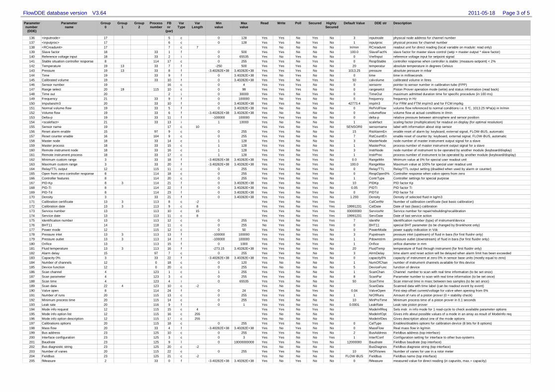
Parameternumber
(DDE)
Parametername
Group0
Group1
Group2
Processnumber
FBnr
(par)
VarType
VarLength
Minvalue
Maxvalue
Read Write Poll Secured Highly Secured
Default Value Description
2011-05-18 Page 3 of 5FlowDDE database version V3.64
DDE str
136 <inputnode> 17 5 c 0 128 Yes Yes No Yes No 3 physical node address for channel numberinputnode137 <inputproc> 17 6 c 0 128 Yes Yes No Yes No 1 physical process for channel numberinputproc138 <RCreadunit> 17 7 c 7 Yes No No No No ln/min readout unit for direct reading (local variable on module: read only)RCreadunit139 Slave factor 18 33 1 f 0 500 Yes Yes No No No 100.0 slave factor for master slave control (setp = master output * slave factor)SlaveFact%140 Reference voltage input 18 33 2 i 0 65535 Yes No Yes No No 0 reference voltage input for setpoint signalVrefInput141 Stable situation controller response 8 114 17 c 0 255 Yes Yes No Yes No 0 controller response when controller is stable: |measure-setpoint| < 2%RespStable142 Temperature 19 13 33 7 f -250 500 Yes Yes Yes No No 20 absolute temperature in degrees Celsiustemperatur143 Pressure 19 13 33 8 f -3.40282E+38 3.40282E+38 Yes Yes Yes No No 1013.25 absolute pressure in mbarpressure144 Time 19 33 9 f 0 3.40282E+38 Yes No Yes No No 0 time in millisecondstime145 Calibrated volume 19 33 10 f 0 3.40282E+38 Yes Yes No Yes No 50 calibrated volume in litrescalvolume146 Sensor number 19 16 c 0 4 Yes Yes Yes No No 0 pointer to sensor number in calibration tube (FPP)sensornr147 Range select 20 19 115 10 c 0 99 Yes Yes Yes No No 0 Piston Prover operation mode (write) and status information (read back)rangeselct148 Time out 20 2 i 0 30000 Yes Yes No Yes No 0 maximum admitted duration time for specific procedure (in 100 ms)TimeOut149 Frequency 21 33 9 f 0 100000 Yes No Yes No No 0 frequency in Hzfrequency150 Impulses/m3 20 33 10 f 0 3.40282E+38 Yes Yes No Yes No 42773.4 For FRM and FTM imp/m3 and for FCM imp/kgimp/m3151 Normal volume flow 19 33 5 f 0 3.40282E+38 Yes No No No No 0 volume flow referenced to normal conditions i.e. 0 °C, 1013.25 hPa(a) in ln/minRefVolFlow152 Volume flow 19 33 6 f -3.40282E+38 3.40282E+38 Yes No No No No 0 volume flow at actual conditions in l/minvolumeflow153 Delta-p 19 33 11 f -100000 100000 Yes Yes Yes No No 0 relative pressure between atmosphere and sensor positiondelta-p154 <scalefact> 21 33 13 i 1 10000 Yes No No No No 1 scaling factor (multiplication) for readout on display (for optimal resolution)scalefact155 Sensor name 19 17 c 10 Yes Yes No Yes No SENSOR0 label with information about stop sensorsensorname156 Reset alarm enable 15 97 9 c 0 255 Yes Yes No No No 15 enable reset of alarm by: keyboard, external signal, FLOW-BUS, automaticRstAlarmEn157 Reset counter enable 16 104 9 c 0 255 Yes Yes No No No 7 enable reset of counter by: keyboard, external signal, FLOW-BUS, automaticRstCountEn158 Master node 18 33 14 c 1 128 Yes Yes No No No 3 node number of master instrument output signal for a slaveMasterNode159 Master process 18 33 15 c 1 128 Yes Yes No No No 1 process number of master instrument output signal for a slaveMasterProc160 Remote instrument node 18 33 16 c 1 128 Yes Yes No Yes No 3 node number of instrument to be operated by another module (keyboard/display)InstrNode161 Remote instrument process 18 33 17 c 1 128 Yes Yes No Yes No 1 process number of instrument to be operated by another module (keyboard/display)InstrProc162 Minimum custom range 3 33 18 f -3.40282E+38 3.40282E+38 Yes Yes No Yes No 0.0 Mnimum value at 0% for special user readout unitRangeMin163 Maximum custom range 3 33 20 f -3.40282E+38 3.40282E+38 Yes Yes No Yes No 100.0 Maximum value at 100% for special user readout unitRangeMax164 Relay/TTL output 12 115 11 c 0 255 Yes Yes No Yes No 0 Relay/TTL output setting (disabled when used by alarm or counter)Relay/TTL165 Open from zero controller response 8 114 18 c 0 255 Yes Yes No Yes No 0 Controller response when valve opens from zeroRespOpen0%166 Controller features 8 114 20 c 0 255 Yes Yes No Yes No 1 Controller settings for special purposeContrType167 PID-Kp 8 3 114 21 f 0 3.40282E+38 Yes Yes No Yes No 10 PID factor KpPIDKp168 PID-Ti 8 114 22 f 0 3.40282E+38 Yes Yes No Yes No 0.05 PID factor TiPIDTi169 PID-Td 8 114 23 f 0 3.40282E+38 Yes Yes No Yes No 0 PID factor TdPIDTd170 Density 3 33 21 f 0 3.40282E+38 Yes Yes No Yes No 1.293 Density of selected fluid in kg/m3Density171 Calibration certificate 13 3 113 8 c -2 Yes Yes No Yes Yes Number of calibration certificate (last basic calibration)CalCertNr172 Calibration date 13 3 113 9 c 8 Yes Yes No Yes Yes 19991231 Date of last (basic) calibrationCalDate173 Service number 13 113 10 c 15 Yes Yes No Yes Yes 00000000 Service number for repair/rebuilding/recalibrationServiceNr174 Service date 13 113 11 c 8 Yes Yes No Yes Yes 19991231 Date of last service actionServDate175 Identification number 13 113 12 c 0 255 Yes Yes No Yes Yes 7 Identification number (type) of instrument/deviceIdentNr176 BHT11 14 118 11 c 0 255 No Yes No Yes Yes 0 special BHT parameter (to be changed by Bronkhorst only)BHT11177 Power mode 12 115 12 c 0 50 Yes Yes No Yes No 0 power supply indication in VdcPowerMode178 Pressure inlet 13 3 113 13 f -100000 100000 Yes Yes No Yes No 3 pressure inlet (upstream) of fluid in bara (for first fluidnr only)Pupstream179 Pressure outlet 13 3 113 14 f -100000 100000 Yes Yes No Yes No 1 pressure outlet (downstream) of fluid in bara (for first fluidnr only)Pdownstrm180 Orifice 13 113 15 f 0 1000 Yes Yes No Yes No 1 orifice diameter in mmOrifice181 Fluid temperature 13 3 113 16 f -273.15 3.40282E+38 Yes Yes No Yes No 20 temperature of fluid through instrument (for first fluidnr only)FluidTemp182 Alarm delay 15 97 7 c 0 255 Yes Yes No No No 3 time alarm and reset action will be delayed when alarm limit has been exceededAlrmDelay183 Capacity 0% 3 33 22 f -3.40282E+38 3.40282E+38 Yes Yes No Yes No 0 capacity of instrument at zero 0% in sensor base units (mostly equal to zero)capacity0%184 Number of channels 12 0 18 c 0 120 Yes No No No No 1 number of instrument channels available for this deviceNumOfChan185 Device function 12 0 20 c 0 255 Yes No No No No 5 function of deviceDeviceFunc186 Scan channel 4 123 1 c 1 255 Yes Yes No No No 1 Channel number to scan with real time information (to be set once)ScanChan187 Scan parameter 4 123 3 c 0 255 Yes Yes No No No 8 Parameter number to scan with real time information (to be set once)ScanPar188 Scan time 4 123 4 i 0 65535 Yes Yes No No No 50 Scan interval time in msec between two samples (to be set once)ScanTime189 Scan data 22 4 123 10 c -2 Yes No No No No Scanned data with time label (can be readout event by event)ScanData190 Valve open 8 114 24 f 0 24 Yes Yes No Yes No 0.04 First-step offset current/voltage for valve when opening from 0%ValveOpen191 Number of runs 20 115 13 c 0 255 Yes Yes No No No 1 Amount of runs of a piston prover (0 = stability check)NrOfRuns192 Minimum process time 20 115 14 c 0 255 Yes Yes No No No 10 Minimum process time of a piston prover in 0.1 secondsMinProTime193 Leak rate 20 116 9 f 0 1 Yes Yes No Yes No 0.0001 Leak rate piston proverLeakRate194 Mode info request 12 115 15 c 4 Yes Yes No Yes No Sets instr. in info mode for 1 read-cycle to check available parameter optionsModeInfReq195 Mode info option list 12 115 16 c 255 Yes No No No No Gives info about possible values of a mode in an array as result of ModeInfo reqModeInfOpt196 Mode info option description 12 115 17 c 255 Yes No No No No Gives description about one of the mode optionsModeInfDes197 Calibrations options 20 115 18 c 0 255 Yes Yes No Yes No 0 Enables/disables options for calibration device (8 bits for 8 options)CalType198 Mass flow 20 33 4 f -3.40282E+38 3.40282E+38 Yes No Yes No No 0 Real mass flow in kg/minMassFlow199 Bus address 23 125 10 c 0 255 Yes Yes No Yes No 2 Fieldbus address (top interface)BusAddress200 Interface configuration 23 125 3 c 0 3 Yes Yes No No Yes 1 Configuration setting for interface to other bus-systemsInterfConf201 Baudrate 23 125 9 l 0 10000000000 Yes Yes No Yes No 12000000 Fieldbus baudrate (top interface)Baudrate202 Bus diagnostic string 23 125 20 c -2 Yes No No No No Fieldbus diagnose string (top interface)BusDiagnos203 Number of vanes 20 115 22 c 0 255 Yes Yes No Yes No 10 Number of vanes for use in a rotor meterNrOfVanes204 Fieldbus 23 125 21 c -2 Yes No No No No FLOW-BUS Fieldbus name (top interface)Fieldbus205 fMeasure 2 33 0 f -3.40282E+38 3.40282E+38 Yes No Yes No No 0 measured value for direct reading (in capunits, max.= capacity)fMeasure
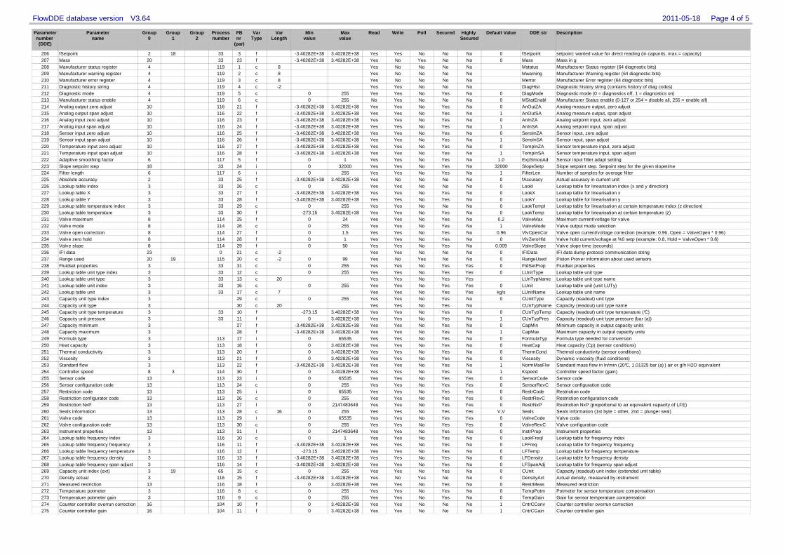
Parameternumber
(DDE)
Parametername
Group0
Group1
Group2
Processnumber
FBnr
(par)
VarType
VarLength
Minvalue
Maxvalue
Read Write Poll Secured Highly Secured
Default Value Description
2011-05-18 Page 4 of 5FlowDDE database version V3.64
DDE str
206 fSetpoint 2 18 33 3 f -3.40282E+38 3.40282E+38 Yes Yes No No No 0 setpoint: wanted value for direct reading (in capunits, max.= capacity)fSetpoint207 Mass 20 33 23 f -3.40282E+38 3.40282E+38 Yes No Yes No No 0 Mass in gMass208 Manufacturer status register 4 119 1 c 8 Yes No No No No Manufacturer Status register (64 diagnostic bits)Mstatus209 Manufacturer warning register 4 119 2 c 8 Yes No No No No Manufacturer Warning register (64 diagnostic bits)Mwarning210 Manufacturer error register 4 119 3 c 8 Yes No No No No Manufacturer Error register (64 diagnostic bits)Merror211 Diagnostic history string 4 119 4 c -2 Yes Yes No No No Diagnostic history string (contains history of diag codes)DiagHist212 Diagnostic mode 4 119 5 c 0 255 Yes Yes No Yes No 0 Diagnostic mode (0 = diagnostics off, 1 = diagnostics on)DiagMode213 Manufacturer status enable 4 119 6 c 0 255 No Yes No No No 0 Manufacturer Status enable (0-127 or 254 = disable all, 255 = enable all)MStatEnabl214 Analog output zero adjust 10 116 21 f -3.40282E+38 3.40282E+38 Yes Yes No Yes No 0 Analog measure output, zero adjustAnOutZA215 Analog output span adjust 10 116 22 f -3.40282E+38 3.40282E+38 Yes Yes No Yes No 1 Analog measure output, span adjustAnOutSA216 Analog input zero adjust 10 116 23 f -3.40282E+38 3.40282E+38 Yes Yes No Yes No 0 Analog setpoint input, zero adjustAnInZA217 Analog input span adjust 10 116 24 f -3.40282E+38 3.40282E+38 Yes Yes No Yes No 1 Analog setpoint input, span adjustAnInSA218 Sensor input zero adjust 10 116 25 f -3.40282E+38 3.40282E+38 Yes Yes No Yes No 0 Sensor input, zero adjustSensInZA219 Sensor input span adjust 10 116 26 f -3.40282E+38 3.40282E+38 Yes Yes No Yes No 1 Sensor input, span adjustSensInSA220 Temperature input zero adjust 10 116 27 f -3.40282E+38 3.40282E+38 Yes Yes No Yes No 0 Sensor temperature input, zero adjustTempInZA221 Temperature input span adjust 10 116 28 f -3.40282E+38 3.40282E+38 Yes Yes No Yes No 1 Sensor temperature input, span adjustTempInSA222 Adaptive smoothing factor 6 117 5 f 0 1 Yes Yes No Yes No 1.0 Sensor input filter adapt settingExpSmooAd223 Slope setpoint step 18 33 24 i 0 32000 Yes Yes No Yes No 32000 Slope setpoint step. Setpoint step for the given slopetimeSlopeSetp224 Filter length 6 117 6 i 0 255 Yes Yes No Yes No 1 Number of samples for average filterFilterLen225 Absolute accuracy 2 33 25 f -3.40282E+38 3.40282E+38 Yes No No No No 0 Actual accuracy in current unitfAccuracy226 Lookup table index 3 33 26 c 0 255 Yes Yes No No No 0 Lookup table for linearisation index (x and y direction)LookI227 Lookup table X 3 33 27 f -3.40282E+38 3.40282E+38 Yes Yes No Yes No 0 Lookup table for linearisation xLookX228 Lookup table Y 3 33 28 f -3.40282E+38 3.40282E+38 Yes Yes No Yes No 0 Lookup table for linearisation yLookY229 Lookup table temperature index 3 33 29 c 0 255 Yes Yes No No No 0 Lookup table for linearisation at certain temperature index (z direction)LookTempI230 Lookup table temperature 3 33 30 f -273.15 3.40282E+38 Yes Yes No Yes No 0 Lookup table for linearisation at certain temperature (z)LookTemp231 Valve maximum 8 114 25 f 0 24 Yes Yes No Yes No 0.2 Maximum current/voltage for valveValveMax232 Valve mode 8 114 26 c 0 255 Yes Yes No Yes No 1 Valve output mode selectionValveMode233 Valve open correction 8 114 27 f 0 1.5 Yes Yes No Yes No 0.96 Valve open current/voltage correction (example: 0.96, Open = ValveOpen * 0.96)VlvOpenCor234 Valve zero hold 8 114 28 f 0 1 Yes Yes No Yes No 0 Valve hold current/voltage at %0 setp (example: 0.8, Hold = ValveOpen * 0.8)VlvZeroHld235 Valve slope 8 114 29 f 0 50 Yes Yes No Yes No 0.009 Valve slope time (seconds)ValveSlope236 IFI data 23 0 21 c -2 Yes Yes No No No 0 IFI data dump protocol communication stringIFIData237 Range used 20 19 115 20 c -2 0 99 Yes No Yes No No 0 Piston Prover information about used sensorsRangeUsed238 Fluidset properties 3 33 31 c 0 255 Yes Yes No Yes Yes 0 Fluidset propertiesFldSetProp239 Lookup table unit type index 3 33 12 c 0 255 Yes Yes No Yes Yes 0 Lookup table unit typeLUnitType240 Lookup table unit type 3 33 13 c 20 Yes Yes No Yes Yes Lookup table unit type nameLUnTypName241 Lookup table unit index 3 33 16 c 0 255 Yes Yes No Yes Yes 0 Lookup table unit (unit LUTy)LUnit242 Lookup table unit 3 33 17 c 7 Yes Yes No Yes Yes kg/s Lookup table unit nameLUnitName243 Capacity unit type index 3 29 c 0 255 Yes Yes No Yes No 0 Capacity (readout) unit typeCUnitType244 Capacity unit type 3 30 c 20 Yes Yes No Yes No Capacity (readout) unit type nameCUnTypName245 Capacity unit type temperature 3 33 10 f -273.15 3.40282E+38 Yes Yes No Yes No 0 Capacity (readout) unit type temperature (°C)CUnTypTemp246 Capacity unit pressure 3 33 11 f 0 3.40282E+38 Yes Yes No Yes No 1 Capacity (readout) unit type pressure (bar (a))CUnTypPres247 Capacity minimum 3 27 f -3.40282E+38 3.40282E+38 Yes Yes No Yes No 0 Minimum capacity in output capacity unitsCapMin248 Capacity maximum 3 28 f -3.40282E+38 3.40282E+38 Yes Yes No Yes No 1 Maximum capacity in output capacity unitsCapMax249 Formula type 3 113 17 i 0 65535 Yes Yes No Yes No 0 Formula type needed for conversionFormulaTyp250 Heat capacity 3 113 18 f 0 3.40282E+38 Yes Yes No Yes No 0 Heat capacity (Cp) (sensor conditions)HeatCap251 Thermal conductivity 3 113 20 f 0 3.40282E+38 Yes Yes No Yes No 0 Thermal conductivity (sensor conditions)ThermCond252 Viscosity 3 113 21 f 0 3.40282E+38 Yes Yes No Yes No 0 Dynamic viscosity (fluid conditions)Viscosity253 Standard flow 3 113 22 f -3.40282E+38 3.40282E+38 Yes Yes No Yes No 1 Standard mass flow in ln/min (20°C, 1.01325 bar (a) ) air or g/h H2O equivalentNormMasFlw254 Controller speed 8 3 114 30 f 0 3.40282E+38 Yes Yes No Yes No 1 Controller speed factor (gain)Kspeed255 Sensor code 13 113 23 i 0 65535 Yes Yes No Yes Yes 0 Sensor codeSensorCode256 Sensor configuration code 13 113 24 c 0 255 Yes Yes No Yes Yes 0 Sensor configuration codeSensorRevC257 Restriction code 13 113 25 i 0 65535 Yes Yes No Yes Yes 0 Restriction codeRestrCode258 Restriction configurator code 13 113 26 c 0 255 Yes Yes No Yes Yes 0 Restriction configuration codeRestrRevC259 Restriction NxP 13 113 27 l 0 2147483648 Yes Yes No Yes Yes 0 Restriction NxP (proportional to air equivalent capacity of LFE)RestrNxP260 Seals information 13 113 28 c 16 0 255 Yes Yes No Yes Yes V,V Seals information (1st byte = other, 2nd = plunger seal)Seals261 Valve code 13 113 29 i 0 65535 Yes Yes No Yes Yes 0 Valve codeValveCode262 Valve configuration code 13 113 30 c 0 255 Yes Yes No Yes Yes 0 Valve configuration codeValveRevC263 Instrument properties 13 113 31 l 0 2147483648 Yes Yes No Yes Yes 0 Instrument propertiesInstrProp264 Lookup table frequency index 3 116 10 c 0 1 Yes Yes No Yes No 0 Lookup table for frequency indexLookFreqI265 Lookup table frequency frequency 3 116 11 f -3.40282E+38 3.40282E+38 Yes Yes No Yes No 0 Lookup table for frequency frequencyLFFreq266 Lookup table frequency temperature 3 116 12 f -273.15 3.40282E+38 Yes Yes No Yes No 0 Lookup table for frequency temperatureLFTemp267 Lookup table frequency density 3 116 13 f -3.40282E+38 3.40282E+38 Yes Yes No Yes No 0 Lookup table for frequency densityLFDensity268 Lookup table frequency span adjust 3 116 14 f -3.40282E+38 3.40282E+38 Yes Yes No Yes No 0 Lookup table for frequency span adjustLFSpanAdj269 Capacity unit index (ext) 3 19 65 15 c 0 255 Yes Yes No Yes No 0 Capacity (readout) unit index (extended unit table)CUnit270 Density actual 3 116 15 f -3.40282E+38 3.40282E+38 Yes No Yes No No 0 Actual density, measured by instrumentDensityAct271 Measured restriction 13 116 18 f 0 3.40282E+38 Yes Yes No Yes No 0 Measured restrictionRestrMeas272 Temperature potmeter 3 116 8 c 0 255 Yes Yes No Yes No 0 Potmeter for sensor temperature compensationTempPotm273 Temperature potmeter gain 3 116 9 c 0 255 Yes Yes No Yes No 0 Gain for sensor temperature compensationTempGain274 Counter controller overrun correction 16 104 10 f 0 3.40282E+38 Yes Yes No No No 1 Counter controller overrun correctionCntrCConv275 Counter controller gain 16 104 11 f 0 3.40282E+38 Yes Yes No No No 1 Counter controller gainCntrCGain
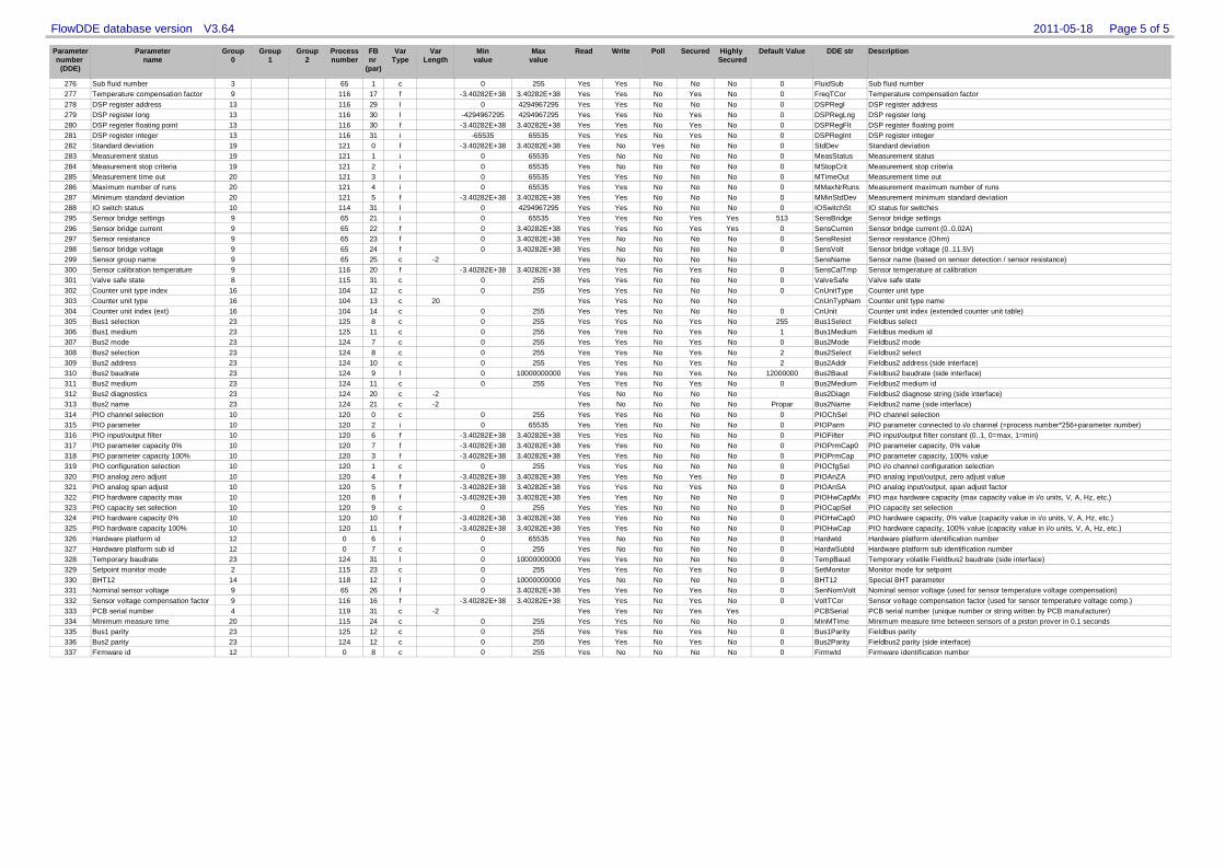
Parameternumber
(DDE)
Parametername
Group0
Group1
Group2
Processnumber
FBnr
(par)
VarType
VarLength
Minvalue
Maxvalue
Read Write Poll Secured Highly Secured
Default Value Description
2011-05-18 Page 5 of 5FlowDDE database version V3.64
DDE str
276 Sub fluid number 3 65 1 c 0 255 Yes Yes No No No 0 Sub fluid numberFluidSub277 Temperature compensation factor 9 116 17 f -3.40282E+38 3.40282E+38 Yes Yes No Yes No 0 Temperature compensation factorFreqTCor278 DSP register address 13 116 29 l 0 4294967295 Yes Yes No No No 0 DSP register addressDSPRegI279 DSP register long 13 116 30 l -4294967295 4294967295 Yes Yes No Yes No 0 DSP register longDSPRegLng280 DSP register floating point 13 116 30 f -3.40282E+38 3.40282E+38 Yes Yes No Yes No 0 DSP register floating pointDSPRegFlt281 DSP register integer 13 116 31 i -65535 65535 Yes Yes No Yes No 0 DSP register integerDSPRegInt282 Standard deviation 19 121 0 f -3.40282E+38 3.40282E+38 Yes No Yes No No 0 Standard deviationStdDev283 Measurement status 19 121 1 i 0 65535 Yes No No No No 0 Measurement statusMeasStatus284 Measurement stop criteria 19 121 2 i 0 65535 Yes No No No No 0 Measurement stop criteriaMStopCrit285 Measurement time out 20 121 3 i 0 65535 Yes Yes No No No 0 Measurement time outMTimeOut286 Maximum number of runs 20 121 4 i 0 65535 Yes Yes No No No 0 Measurement maximum number of runsMMaxNrRuns287 Minimum standard deviation 20 121 5 f -3.40282E+38 3.40282E+38 Yes Yes No No No 0 Measurement minimum standard deviationMMinStdDev288 IO switch status 10 114 31 l 0 4294967295 Yes Yes No No No 0 IO status for switchesIOSwitchSt295 Sensor bridge settings 9 65 21 i 0 65535 Yes Yes No Yes Yes 513 Sensor bridge settingsSensBridge296 Sensor bridge current 9 65 22 f 0 3.40282E+38 Yes Yes No Yes Yes 0 Sensor bridge current (0..0.02A)SensCurren297 Sensor resistance 9 65 23 f 0 3.40282E+38 Yes No No No No 0 Sensor resistance (Ohm)SensResist298 Sensor bridge voltage 9 65 24 f 0 3.40282E+38 Yes No No No No 0 Sensor bridge voltage (0..11.5V)SensVolt299 Sensor group name 9 65 25 c -2 Yes No No No No Sensor name (based on sensor detection / sensor resistance)SensName300 Sensor calibration temperature 9 116 20 f -3.40282E+38 3.40282E+38 Yes Yes No Yes No 0 Sensor temperature at calibrationSensCalTmp301 Valve safe state 8 115 31 c 0 255 Yes Yes No No No 0 Valve safe stateValveSafe302 Counter unit type index 16 104 12 c 0 255 Yes Yes No No No 0 Counter unit typeCnUnitType303 Counter unit type 16 104 13 c 20 Yes Yes No No No Counter unit type nameCnUnTypNam304 Counter unit index (ext) 16 104 14 c 0 255 Yes Yes No No No 0 Counter unit index (extended counter unit table)CnUnit305 Bus1 selection 23 125 8 c 0 255 Yes Yes No Yes No 255 Fieldbus selectBus1Select306 Bus1 medium 23 125 11 c 0 255 Yes Yes No Yes No 1 Fieldbus medium idBus1Medium307 Bus2 mode 23 124 7 c 0 255 Yes Yes No Yes No 0 Fieldbus2 modeBus2Mode308 Bus2 selection 23 124 8 c 0 255 Yes Yes No Yes No 2 Fieldbus2 selectBus2Select309 Bus2 address 23 124 10 c 0 255 Yes Yes No Yes No 2 Fieldbus2 address (side interface)Bus2Addr310 Bus2 baudrate 23 124 9 l 0 10000000000 Yes Yes No Yes No 12000000 Fieldbus2 baudrate (side interface)Bus2Baud311 Bus2 medium 23 124 11 c 0 255 Yes Yes No Yes No 0 Fieldbus2 medium idBus2Medium312 Bus2 diagnostics 23 124 20 c -2 Yes No No No No Fieldbus2 diagnose string (side interface)Bus2Diagn313 Bus2 name 23 124 21 c -2 Yes No No No No Propar Fieldbus2 name (side interface)Bus2Name314 PIO channel selection 10 120 0 c 0 255 Yes Yes No No No 0 PIO channel selectionPIOChSel315 PIO parameter 10 120 2 i 0 65535 Yes Yes No No No 0 PIO parameter connected to i/o channel (=process number*256+parameter number)PIOParm316 PIO input/output filter 10 120 6 f -3.40282E+38 3.40282E+38 Yes Yes No No No 0 PIO input/output filter constant (0..1, 0=max, 1=min)PIOFilter317 PIO parameter capacity 0% 10 120 7 f -3.40282E+38 3.40282E+38 Yes Yes No No No 0 PIO parameter capacity, 0% valuePIOPrmCap0318 PIO parameter capacity 100% 10 120 3 f -3.40282E+38 3.40282E+38 Yes Yes No No No 0 PIO parameter capacity, 100% valuePIOPrmCap319 PIO configuration selection 10 120 1 c 0 255 Yes Yes No No No 0 PIO i/o channel configuration selectionPIOCfgSel320 PIO analog zero adjust 10 120 4 f -3.40282E+38 3.40282E+38 Yes Yes No Yes No 0 PIO analog input/output, zero adjust valuePIOAnZA321 PIO analog span adjust 10 120 5 f -3.40282E+38 3.40282E+38 Yes Yes No Yes No 0 PIO analog input/output, span adjust factorPIOAnSA322 PIO hardware capacity max 10 120 8 f -3.40282E+38 3.40282E+38 Yes Yes No No No 0 PIO max hardware capacity (max capacity value in i/o units, V, A, Hz, etc.)PIOHwCapMx323 PIO capacity set selection 10 120 9 c 0 255 Yes Yes No No No 0 PIO capacity set selectionPIOCapSel324 PIO hardware capacity 0% 10 120 10 f -3.40282E+38 3.40282E+38 Yes Yes No No No 0 PIO hardware capacity, 0% value (capacity value in i/o units, V, A, Hz, etc.)PIOHwCap0325 PIO hardware capacity 100% 10 120 11 f -3.40282E+38 3.40282E+38 Yes Yes No No No 0 PIO hardware capacity, 100% value (capacity value in i/o units, V, A, Hz, etc.)PIOHwCap326 Hardware platform id 12 0 6 i 0 65535 Yes No No No No 0 Hardware platform identification numberHardwId327 Hardware platform sub id 12 0 7 c 0 255 Yes No No No No 0 Hardware platform sub identification numberHardwSubId328 Temporary baudrate 23 124 31 l 0 10000000000 Yes Yes No No No 0 Temporary volatile Fieldbus2 baudrate (side interface)TempBaud329 Setpoint monitor mode 2 115 23 c 0 255 Yes Yes No Yes No 0 Monitor mode for setpointSetMonitor330 BHT12 14 118 12 l 0 10000000000 Yes No No No No 0 Special BHT parameterBHT12331 Nominal sensor voltage 9 65 26 f 0 3.40282E+38 Yes Yes No Yes No 0 Nominal sensor voltage (used for sensor temperature voltage compensation)SenNomVolt332 Sensor voltage compensation factor 9 116 16 f -3.40282E+38 3.40282E+38 Yes Yes No Yes No 0 Sensor voltage compensation factor (used for sensor temperature voltage comp.)VoltTCor333 PCB serial number 4 119 31 c -2 Yes Yes No Yes Yes PCB serial number (unique number or string written by PCB manufacturer)PCBSerial334 Minimum measure time 20 115 24 c 0 255 Yes Yes No No No 0 Minimum measure time between sensors of a piston prover in 0.1 secondsMinMTime335 Bus1 parity 23 125 12 c 0 255 Yes Yes No Yes No 0 Fieldbus parityBus1Parity336 Bus2 parity 23 124 12 c 0 255 Yes Yes No Yes No 0 Fieldbus2 parity (side interface)Bus2Parity337 Firmware id 12 0 8 c 0 255 Yes No No No No 0 Firmware identification numberFirmwId