rr concepts s m tationaster - 5realisitic reversing (more details in manual) the stationmaster works...
TRANSCRIPT

1
This manual contains detailed hookup and programming instructions for the StationMaster train controller available in a 4 AMP or 10AMP configuration.
The StationMaster can control DC trains or DCC equipped trains set to linear mode.
Before we Start- Please do not attach power wires (from your power pack or transformer) to any other terminals except the designated input pins 1 and 2.Your StationMaster will be damaged if power is put on any of the sensor terminals.
ONLY ATTACH WIRES WHILE THE POWER IS OFF.Also, please use the correct size screwdriver for the screw-down terminals. if the bladeis too wide the terminals will be damaged and the screws WILL fall out. This is damage not covered under warranty. The RR Concepts Magnet/Screwdriver tool is recommended.
tation aster - Train Controller
Status LED
Top Speed Adjust and Programming Dial Out to YardMaster data
cable connector.
IN 8-18VDC
Out to Track
Sensor LED
ProgrammingPushbuttons
Sensor Inputs:
DECEL
ACCEL
STOP
RR Concepts
S M
July 13, 2016
5
See decal on bottom for optional programming information

2
Status LED
Top Speed Adjust and Programming Dial
“Out to YardMaster” data cable connector for sidingcontrol hookups.
IN 8-18VDC
Out to Track
See the label on the bottom for programming and additional information.
Sensor LED
ProgrammingPushbuttons
Sensor Inputs:
DECEL
ACCEL
STOP
tation aster - Basic Hookup Instructions
RR Concepts
S M 5 How to doRealistic Station Stops & Realisitic Reversing (More details in manual) The StationMaster works with DC (out of the box)or DCC trains set to linear mode. (N, HO, G, etc.) AC trains cannot be controlled.
sensor
Stopping Position
To Power Pack TRACKTerminals
To Power Pack TRACKTerminals
Attach to TRACK.Swap these wires to go theopposite direction
1
2
3
4
8
9
10
11
12
13
StationMaster
Accelerate + Decelerate Station Stop Hookup
1) Attach terminals 1 & 2 to the transformer. 2) Attach terminals 3 & 4 to the track.3) Attach terminals 8 & 9 to a train sensor. (No polarity)4) Mount a magnet on an engine or car.Set the transformer to the esired top speed. That’s it!
See the online manual for optional additional features:* Set acceleration rate, * Set deceleration rate,* Add additional station stops, * Do multiple laps before stopping, * Set station stop pause duration,* Do exact “self-adjusting deceleration” stopping position.
Accelerate + Decelerate Reversing Hookup
1) Attach terminals 1 & 2 to the transformer.2) Attach terminals 3 & 4 to the track.3) Attach terminals 8 & 9 to train sensors near the ends.4) Mount a magnet on the engine.5) Program the StationMaster for “Blink 1” (see below for programming)
See the online manual for additional in-between stops, delay times, etc,
To TRACK
Sensors in PARALLEL.
1
2
3
4
8
9
10
11
12
13
StationMaster
How to program “Blink 1” reversing mode:1. Turn the top speed dial fully counter-clockwise.2. Turn the top speed dial slowly clockwise until the GREEN LED comes on.3. Press and hold button #1 for 1 blink and then release. (See the manual for more details)4. Turn the top speed dial fully clockwise.
SCAN FOR INFO
4 AMP Version shown, Also available in 10 AMP configuration.
StationMaster CONNECTIONS and CONTROLS
Go to StationMaster.net and download the 25 page user manual for more info.Visit RailroadConcepts.com for more fun, advanced hookups, and ordering parts.
Un-modified track!No diodes, no breaks, no additional track connections.
Reversing
Station Stop

3
StationMaster Basic Hookup Description
The StationMaster is designed to be installedbetween the train transformer, and the track.
Attach terminals 1 & 2 to your transformer's DC output (Sometimes labeled as TRACK) or to a constant 12 volt power source. If using a train transformer set the throttle position to the desired top speed of the train. If the StationMaster does not "light up", then reverse the direction on the transformer to change the voltage polarity, or swap these two wires.
Attach 3 & 4 to your track. This is the controlled output voltage that accelerates and decelerates the train. Pin 3 will be the “common” wire which is the right rail for Large Scale trains or the left rail for NMRA standard trains.
Terminals 8 & 9 are the start DECEL sensor input.When these terminals are closed (sensor detects a magnet) the StationMaster will begin a decelerate, pause, and then accelerate sequence. The RED “Sensor LED” will light up for as long as this sensor is detected. By placing multiple sensors wired in parallel, the StationMaster can stop at multiple stations on your railroad.
Pressing button #1 will simulate the DECEL sensor operation.
DECEL Sensor
+-
Left
Right
RRConcepts.com

4
Terminals 10 and 11 are the optional Start Acceleration sensor inputs.
When these terminals are shorted (sensor detects a magnet) the train will start to accelerate.
This sensor is not necessary unless using “Block Control” or the time delay is set for maximum blinks. (See below).
Pressing button #2 will simulate the ACCEL sensor.
When programmed for “Blink1: Simple reversing mode” this sensor will perform anin-between station stop and the ACCEL function will not be operational.
Terminals 12 and 13 are the optional STOP sensor inputs.
ACCEL Sensor
STOP Sensor
When the train is decelerating and these terminals are shorted (sensor detects a magnet), the train will immediately STOP. This sensor is not necessary unless using the “Self AdjustingDeceleration” mode in which case it is mandatory. A STOP sensor will have no affect unless the trainhas already passed over the DECEL sensor.
Pressing button #3 will simulate the STOP sensor.
Optional
RRConcepts.com
5
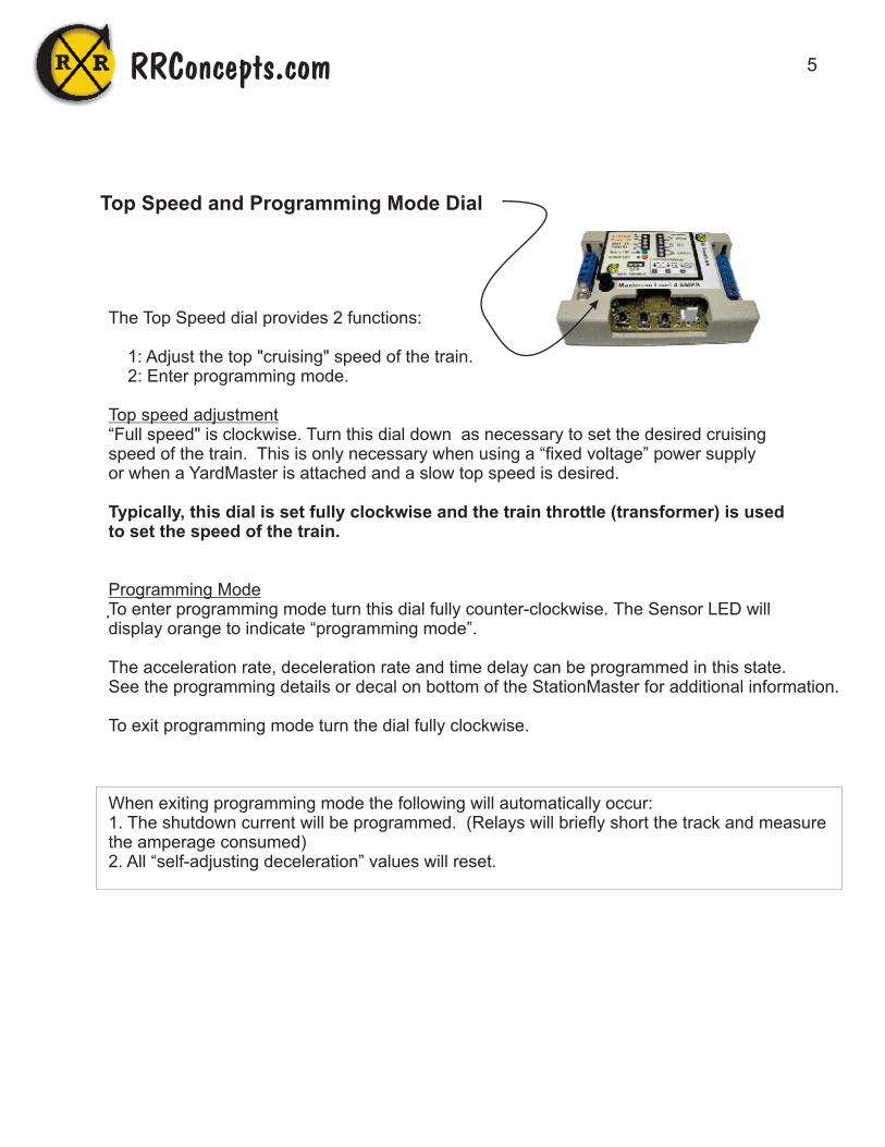
Top Speed and Programming Mode Dial
The Top Speed dial provides 2 functions:
1: Adjust the top "cruising" speed of the train. 2: Enter programming mode.
Top speed adjustment“Full speed" is clockwise. Turn this dial down as necessary to set the desired cruising speed of the train. This is only necessary when using a “fixed voltage” power supplyor when a YardMaster is attached and a slow top speed is desired.
Typically, this dial is set fully clockwise and the train throttle (transformer) is used to set the speed of the train.
Programming ModeTo enter programming mode turn this dial fully counter-clockwise. The Sensor LED will display orange to indicate “programming mode”.
The acceleration rate, deceleration rate and time delay can be programmed in this state.See the programming details or decal on bottom of the StationMaster for additional information.
To exit programming mode turn the dial fully clockwise.
When exiting programming mode the following will automatically occur:1. The shutdown current will be programmed. (Relays will briefly short the track and measure the amperage consumed)2. All “self-adjusting deceleration” values will reset.
RRConcepts.com
6
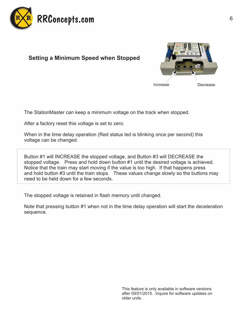
Setting a Minimum Speed when Stopped
The StationMaster can keep a minimum voltage on the track when stopped.
After a factory reset this voltage is set to zero.
When in the time delay operation (Red status led is blinking once per second) thisvoltage can be changed.
Button #1 will INCREASE the stopped voltage, and Button #3 will DECREASE thestopped voltage. Press and hold down button #1 until the desired voltage is achieved.Notice that the train may start moving if the value is too high. If that happens press and hold button #3 until the train stops. These values change slowly so the buttons mayneed to be held down for a few seconds.
The stopped voltage is retained in flash memory until changed.
Note that pressing button #1 when not in the time delay operation will start the decelerationsequence.
RRConcepts.com
Increase Decrease
This feature is only available in software versionsafter 09/01/2015. Inquire for software updates onolder units.

7
Green flashing: train is ACCELERATING. Flash rate indicates the rate of acceleration.
Fast alternating Red/Green Flashing: train is CREEPING and hunting forthe STOP sensor. If flashing orange then the train is CREEPING withthe slowest possible speed for that train. (SM has been programmed for maximum deceleration rate which enables the “self-adjusting deceleration” mode)
Green NOT flashing: Train is AT TOP CRUISING SPEED.
1. Orange NOT flashing, The StationMaster will ignore next DECEL sensor due to lap counting or block control.
2. Orange Flashing, The StationMaster is performing a time delay.
1. Quick Red flashing: Train is DECELERATING. Flash rate indicates the rate of deceleration.
2. Two quick RED flashes at 1 second rate: StationMaster is waiting for the ACCEL sensor before accelerating. (StationMaster Is programmed for infinite time delay)
Sensor RED LED ON or flash: The STOP sensor is detected.The LED will remain on for as long as the sensor is detected. If a train is parked on the STOP sensor then the deceleration sensor will be ignored.
Two Red Blinking LED's indicate a SHORT CIRCUIT condition.Turn the top speed dial to zero and then back to 100%, or turn offpower to recover. If condition returns after recovery check for a short circuiton the track or re-program the shutdown threshold. (Program anything and exit programming mode)
Sensor LED solid GREEN indicates secondary Programming mode.
Sensor LED orange flickering: Indicates programming mode.
STATUS LED
STATUS LED
STATUS LED
STATUS LED
STATUS LED
STATUS LED
STATUS LED
STATUS LED
STATUS LED
STATUS LED
SENSOR LED
SENSOR LED
SENSOR LED
SENSOR LED
SENSOR LED
SENSOR LED
SENSOR LED
SENSOR LED
SENSOR LED
SENSOR LED
LED indicators
RRConcepts.com
8
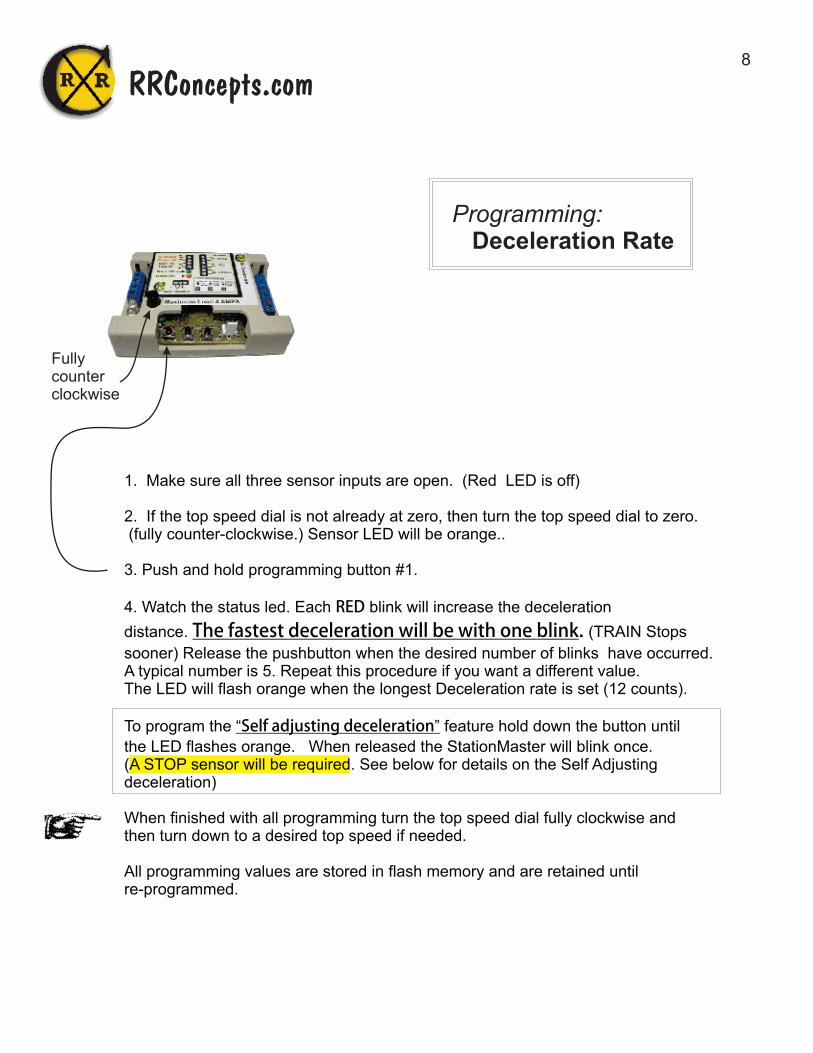
1. Make sure all three sensor inputs are open. (Red LED is off)
2. If the top speed dial is not already at zero, then turn the top speed dial to zero. (fully counter-clockwise.) Sensor LED will be orange..
3. Push and hold programming button #1.
4. Watch the status led. Each RED blink will increase the deceleration
distance. The�fastest�deceleration�will�be�with�one�blink. (TRAIN Stops
sooner) Release the pushbutton when the desired number of blinks have occurred. A typical number is 5. Repeat this procedure if you want a different value. The LED will flash orange when the longest Deceleration rate is set (12 counts). To program the “Self�adjusting�deceleration” feature hold down the button until
the LED flashes orange. When released the StationMaster will blink once. ( . See below for details on the Self Adjusting A STOP sensor will be requireddeceleration)
When finished with all programming turn the top speed dial fully clockwise and then turn down to a desired top speed if needed.
All programming values are stored in flash memory and are retained until re-programmed.
Programming: Deceleration Rate
Fullycounterclockwise
RRConcepts.com

9
1. Make sure all three sensor inputs are open. (Red LED is off)
2. If the top speed dial is not already at zero, then turn the top speed dial to zero. (fully counter-clockwise.) All LED'S will turn off.
3. Press and hold programming button #2..
4. Watch the status led. Each GREEN flash will decrease the acceleration
rate. The�fastest�acceleration�will�be�with�one�blink.Release the button when the desired number of blinks have occurred. A typical number is 5. Repeat this procedure if you want a different value. The LED will blink orange when the longest acceleration rate is set (about 25 counts).
When finished with all programming, increase the top speed dial clockwise to MAX and then down to a desired top speed. All programming values are stored in flash memory and are retained until re-programmed.
An “FYI” Note on Realistic Accelerations:
* For blinks 1 and 2 the train will accelerate with the programmed value. This may berequired for some block control operations where a second train is approachingand the first train needs to quickly accelerate to get out of the way.
* For blinks 3 and above the train will creep very slowly out of the station and thengradually increase the acceleration rate as it continues. This provides a very realisticoperation and shows off train sound systems with incredible realism.
Programming: Acceleration Rate
Fullycounterclockwise
RRConcepts.com

10
1. Make sure all three sensor inputs are open. (red Led is off)
2. If the top speed dial is not already at zero, then turn the top speed dial to zero. (fully counter-clockwise.) All LED'S will turn off.
3. Press and hold programming button #3.
4. Each ORANGE flash will increase the waiting time after a station stop. A�wait�time�of�zero�will�be�with�one�flash.
Release the button when the desired number of flashes have occurred. Repeat this procedure if you want a different value. The LED will turn orange when an infinite delay is set (after 10 counts).When�infinite�delay�is�set,�then�the�ACCEL�sensor�is�required�to�start�up�the��train�after�a�station�stop. A fun thing to do would be to connect the ACCEL terminals to a
doorbell switch. Your train would patiently wait until someone pushed the button! Motionsensors�are�another�possible�way�to�start�the�train.��
When finished with all programming increase the top speed dial clockwise to maximum or to a desired top speed. All programming values are stored in flash memory and are retained until re-programmed.
The number of orange FLASHES will correspond to the following time delays:
1: 0 seconds, no wait. 2: 5 seconds, 3: 10 seconds, 4: 30 seconds, 5: 1 minute, 6: 2 minutes, 7: 5 minutes, 8: 10 minutes, 9: 30 minutes,10: Infinite, wait for GO sensor. This is for block control operations.
Programming: Pause Time
Fullycounterclockwise
RRConcepts.com

11
The operating modes of the StationMaster can be programmed as shown:
1. Enter Secondary Programming mode: (Skip this step if already in secondary programming mode)
* Turn the Top Speed dial fully counter-clockwise to enter programming mode (Skip this step if already in programming mode).
* Turn the Top Speed dial slowly clockwise until the sensor LED turns green. This indicates secondary programming mode. This should be about half-way.
2. Press and hold programming button #1 until the desired number of blinks have occurred.Each blink count will set or clear a different feature.
When finished do not power off without first turning the dial fully clockwise.
StationMaster Programmable Modes (Any or all of these or all can be programmed independently)
Hold button for 1 blink = Simple Reversing Mode, ignore next sensor after reversing, ACCEL sensor will perform an in-between station stop.
Hold button for 2 blinks = Fire YardMaster after train has stopped. (Default ON after a factory reset)
Hold button for 3 blinks = Fire YardMaster before acceleration. (Used for passing sidings)
Hold button for 4 blinks = Use automatic train detection to start deceleration. (No-sensor station stops)
Hold button for 5 blinks = Reverse direction before every acceleration. Never ignore sensors.
Hold button for 6 blinks = Only fire YardMaster in forward direction. (For reversing operations with a siding on one end) Hold button for 7 blinks = Only send Alternate signal to YardMaster. (For reversing operations with sidings on both ends)
When the button is released the StationMaster will echo the currently programmed features (modes)by blinking the red/green LED 7 times. For example, if “Fire YardMaster after train has stopped” hasbeen programmed (button pressed for 2 blinks) and nothing else is programmed then the StationMasterwill blink: blink 1 RED: Reversing mode is OFF. blink 2 GREEN: Fire YardMaster after stopping ON blink 3 RED: Fire YardMaster before acceleration OFF blink 4 RED: Use train sensor to start deceleration OFF blink 5 RED: Reverse direction before every acceleration OFF blink 6 RED: Only fire YardMaster in forward direction OFF blink 7 RED: Only send Alternate signal to YardMaster OFFEach time a feature is programmed that feature will toggle on or off. (Toggle means the feature will go OFF if currently ON, or ON if currently OFF)
Programming: Operating Modes
Please go to RRconcepts.com to view an informational video on how to program operating modes.
To view the currently programmed operating modes quickly press and release button #1 before the RED/GREEN LED blinks. (Must already be in secondary programming mode) The StationMaster will then echo the currently
programmed features. PLEASE DOUBLE CHECK PROGRAMMING. Some hookups will cause short circuits if accidentally programmed for REVERSING operations.
Note that a factory reset will clear all programmed modes and set blink 2.
Green
RRConcepts.com

12
Additional Information on Programming Modes.(See previous page for programming procedure)
blink 1 = Simple Reversing Mode
This will allow reversing operations with a DECEL sensor placed at the ends wired in parallel. After reversing the very next DECEL sensor will be ignored. In-between station stops can be done by adding sensors in parallel to the ACCEL terminals. The train will stop at every location where a sensor is placed. the ACCEL sensor operation will not be operational.
blink 2 = Fire YardMaster after train has stopped. If programmed for more than 1 train the YardMaster will fire to the next siding after the train has stopped. Note that the StationMaster will automatically set this blink after a factory reset.
blink 3 = Fire YardMaster before acceleration.
If programmed for more than 1 train the YardMaster will fire to the next siding before accelerating.
blink 4 = Use automatic train detection to start deceleration.
When a train leaves the StationMaster controlled track and then is sensed entering the track section again the deceleration will start. Deceleration will start at any time the train Is not detected and then detected again.
blink 5 = Reverse direction before every acceleration
This is similar to blink 1 however the StationMaster will not ignore any sensors and the ACCEL sensor will be operational.
blink 6 = Only fire YardMaster in forward direction. (only active in reversing mode)
This will allow a reversing operation with sidings on one end.
blink 7 = Only send ALTERNATE signal to YardMaster.
This is used for a back-and-forth operation with sidings on both ends. (See hookup diagram) Three trains will run between the two sidings.
.
RRConcepts.com

13
Programming: Factory Reset
To set the StationMaster back to factory defaults perform the following:
1: Enter programming mode by turning the top speed dial fully counter-clockwise2. Press and hold both button #1 and button #3. (If buttons are non-operational then short the DECEL and STOP sensor inputs)3. The StationMaster will quickly blink orange to indicate factory reset.4. Save the settings by turning the top speed dial fully clockwise to exit programming mode.Do not power off without first turning the dial fully clockwise.
The factory default settings are:
* Acceleration rate 5 blinks* Deceleration rate 3 blinks.* Time delay 5 seconds.* Train count: 2 (Note: Block control will not be operation until set for 1 train)* Lap count: 1* Operating mode (features):
Blink 1 = RED, Simple Reversing: OFF. Blink 2 = GREEN, Fire YardMaster before accelerating: ON Blink 3 = RED, Fire YardMaster before decelerating: OFF Blink 4 = RED, Use train sense to start deceleration: OFF Blink 5 = RED, Reverse before every acceleration: OFF Blink 6 = RED, Fire YardMaster only in forward direction: OFF
Fullycounterclockwise
RRConcepts.com

14
The StationMaster can be programmed to ignore multiple DECEL sensors to allowrunning up to 10 laps before stopping. To allow multiple laps, program as follows:
1. Turn the Top Speed dial fully counter-clockwise to enter programming mode(Skip this step if already in programming mode).
2. Slowly turn the Top Speed dial clockwise until the GREEN indicator turns on. This indicates secondary programming mode. (Skip this step if already in secondary programming mode)
3. Press and hold button #2.
4. Count the blinks while the button is pressed. Release the button when theappropriate number of blinks have occurred.
The number of blinks corresponds to the number of laps the train will do before stopping as shown:
1 blink = 1 lap,2 blinks = 2 lapsetc...
When finished with all programming, increase the top speed dial clockwise to maximum to exit programming mode. All programming values are stored in flash memory and saved until re-programmed again.
Programming: MULTIPLE LAPS
Green
RRConcepts.com

15
The train count is needed for 3 reasons:1. Perform self adjusting deceleration for up to 5 trains.2. Send proper signals to attached YardMasters to correctly fire turnouts.3. Allow running in a block-control mode. (Must be set for 1 train)
For example, a 3 track siding using 2 YardMasters wired in parallel wouldhave a train count of 3, since 3 trains will be controlled.
For an alternating siding hookup no programming is necessary since the defaulttrain count is 2.
Programming:
1. Make sure all three sensor inputs are open.
2. If not already in programming mode turn the top speed dial to zero. (fully counter-clockwise.)
3. Turn the top speed dial to about half position. This enables the secondary programming options. The sensor LED will turn GREEN to indicate secondary programmingmode. (Skip this step if already in secondary programming mode)
4. Press and hold button #3.
5. Watch the status led. Each orange flash counts the number of running trains.
Release the button when the desired number of flashes have occurred. The number will be echoed back when the button is released.. Repeat this procedure if you want a different value. When finished with all programming, increase the top speed dial clockwise to MAX, and then down to a desired top speed if necessary. All programming values are stored in flash memory and saved until re-programmed again.
NOTICE: A factory reset will set the train count to 2. Block control will not be operational until set for 1 train.
Programming: Train Count
Green
RRConcepts.com
16
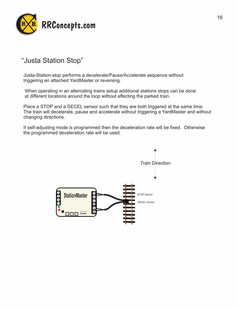
“Justa Station Stop”
Justa-Station-stop performs a decelerate/Pause/Accelerate sequence withouttriggering an attached YardMaster or reversing.
When operating in an alternating trains setup additional stations stops can be done at different locations around the loop without affecting the parked train.
Place a STOP and a DECEL sensor such that they are both triggered at the same time.The train will decelerate, pause and accelerate without triggering a YardMaster and withoutchanging directions.
If self-adjusting mode is programmed then the deceleration rate will be fixed. Otherwisethe programmed deceleration rate will be used.
STOP Sensor
DECEL Sensor
Train Direction
RRConcepts.com
1
2
3
4
8
9
10
11
12
13
StationMaster

17
DECEL sensor
Stopping Position
To Power Pack TRACKTerminals
Attach to TRACK
Basic Hookup Diagram forAutomatic Station Stops with Deceleration/Accelerationusing standard train sensors.
To Left Rail
Place MAGNETon bottom of engine.
Add additional sensors in PARALLEL for additional station stops.
For a simple station stop, this is all you need to do!
RRConcepts.com
1
2
3
4
8
9
10
11
12
13
StationMaster
18
+
-
To Power Pack TRACKTerminals
Attach to TRACK
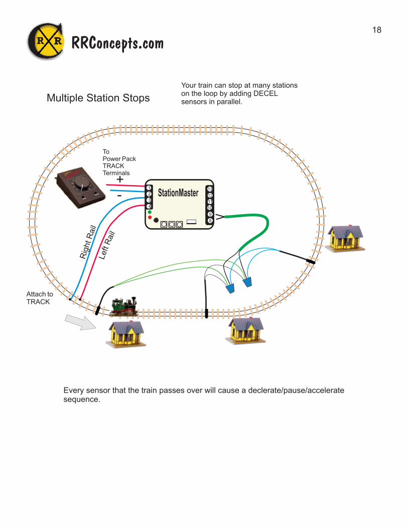
Multiple Station Stops
Your train can stop at many stationson the loop by adding DECELsensors in parallel.
Every sensor that the train passes over will cause a declerate/pause/acceleratesequence.
RRConcepts.com
1
2
3
4
8
9
10
11
12
13
StationMaster

19
ACCEL sensor
DECEL sensor
To Power Pack TRACKTerminalsor fullspeed track.
Isolators
For 1 or 2 Trains on 1 track with gradual Decelerations and Accelerations.Can be located at a remote location on the railroad
Block Control
+
+
-
Programming:* Train count: 1* Time delay: maximum
RRConcepts.com
When ORANGE is displayedthe next DECEL sensor willbe ignored. This preventsa train from stopping if thefollowing trains is too close.This also allows 1 train to be run on the track without stopping.Hitting ACCEL without a train inthe block will set this.
1
2
3
4
8
9
10
11
12
13
StationMaster
Hookup Notes:1. Your train may not stop if the second train is too close. (ACCEL is hit before DECEL)2. When the train decelerates it must stop before reaching the 2nd isolator..3. If the train is slowing or stopped, then the second train will tell it to “go” when it hits the ACCEL sensor. (Start with sensor half-way around the track. Station stop will be longer with ACCEL sensor closer.) Move the location of this sensor to fit your track.5. Location of ACCEL sensor must allow the stopped train time to accelerate and exit before the 2nd train enters the siding.6. This hookup can run with 1 train or 2 trains. (1 train will never stop unless ACCEL sensor is removed)7. A longer isolated section will provide more realism for the stopped train to decelerate and accelerate.8. Station can be located at a remote location on your railroad.
To Power Pack TRACKTerminals. Left rail ispositive. Switch direction if StationMaster does not light up.

20
ACCEL sensor
DECEL sensor
To Power Pack TRACKTerminals
To Power Pack TRACKTerminals
Isolators
+
+
-
Programming:* Train count: 1* Time delay: maximum
When ORANGE is displayedthe next DECEL sensor willbe ignored. This preventsa train from stopping if thefollowing trains is too close.This also allows 1 train to be run on the track without stopping.Hitting ACCEL without a train inthe block will set this.
ACCEL sensor
DECEL sensor
To Power Pack TRACKTerminals
Isolators
+-
For 1, 2, or 3 Trains on 1 track with gradual Decelerations and Accelerations using StationMasters.
Block Control
RRConcepts.com
1
2
3
4
8
9
10
11
12
13
StationMaster
1
2
3
4
8
9
10
11
12
13
StationMaster
21
To Power Pack TRACKTerminals
To Power Pack TRACKTerminals
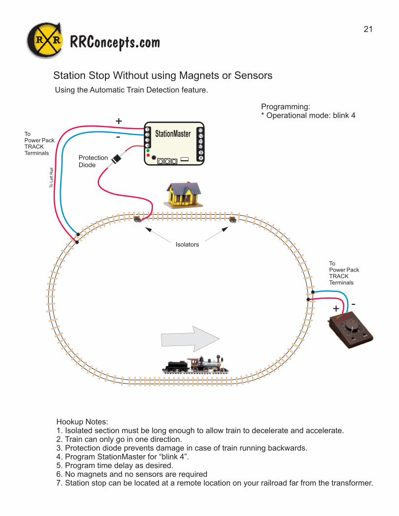
Using the Automatic Train Detection feature.
Station Stop Without using Magnets or Sensors
+
+
-
-
To L
eft R
ail
Hookup Notes:1. Isolated section must be long enough to allow train to decelerate and accelerate.2. Train can only go in one direction.3. Protection diode prevents damage in case of train running backwards.4. Program StationMaster for “blink 4”.5. Program time delay as desired.6. No magnets and no sensors are required7. Station stop can be located at a remote location on your railroad far from the transformer.
Programming:* Operational mode: blink 4
RRConcepts.com
Isolators
Protection Diode
1
2
3
4
8
9
10
11
12
13
StationMaster
22
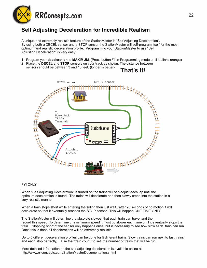
Self Adjusting Deceleration for Incredible Realism
A unique and extremely realistic feature of the StationMaster is “Self Adjusting Deceleration”. By using both a DECEL sensor and a STOP sensor the StationMaster will self-program itself for the most optimum and realistic deceleration profile. Programming your StatiionMaster to use “Self Adjusting Deceleration” is very easy:
1. Program your deceleration to MAXIMUM. (Press button #1 in Programming mode until it blinks orange)2. Place the DECEL and STOP sensors on your track as shown. The distance between sensors should be between 3 and 10 feet. (longer is better)
FYI ONLY:
When “Self Adjusting Deceleration” is turned on the trains will self-adjust each lap until theoptimum deceleration is found. The trains will decelerate and then slowly creep into the station in a very realistic manner.
When a train stops short while entering the siding then just wait.. after 20 seconds of no motion it will accelerate so that it eventually reaches the STOP sensor. This will happen ONE TIME ONLY.
The StationMaster will determine the absolute slowest that each train can travel and thenrecord this speed. To determine this minimum speed it must go slower each time until it eventually stops the train. Stopping short of the sensor only happens once, but is necessary to see how slow each train can run. Once this is done all decelerations will be extremely realistic.
Up to 5 different deceleration profiles can be done for 5 different trains. Slow trains can run next to fast trainsand each stop perfectly, Use the “train count” to set the number of trains that will be run.
More detailed information on the self-adjusting deceleration is available online at http://www.rr-concepts.com/StationMasterDocumentation.shtml
STOP sensor DECEL sensor
To Power Pack TRACKTerminals
Attach to TRACK
+-
That’s it!
RRConcepts.com
1
2
3
4
8
9
10
11
12
13
StationMaster

23
HOOKUP:1 2 To Power Pack DC TRACK Terminals. If StationMaster does not turn on then reverse direction on the transformer.
3 4 To Track
8 9 To DECEL sensors wired in parallel.
12 13 To STOP sensors wired in parallel.
See next page for optional in-between station stops.
To TRACK
Sensors in PARALLEL.
Extremely Realistic Reversing Operations
When programming Mode blink 1 is set the StationMaster will go into reversing mode.
Sensors are placed near the ends to signal the StationMaster to begin the deceleration / pause / accelerate operation. Sensors on the ends stop the train at an exactlocation. Sensors have no polarity. Place sensors about 2 feet apart for realistic operation.Set the deceleration rate to MAXIMUM to enable the self-adjusting deceleration. Set the acceleration rate to 2 blinks for trolleys for a realistic acceleration.
Terminals 8 & 9
Terminals 12 & 13
RRConcepts.com
1
2
3
4
8
9
10
11
12
13
StationMaster
STOP
START DECELERATION
MAGNET on train
The Self-Adjusting Deceleration operationWhen first programmed for self-adjusting deceleration the trains will over-shoot for many cycles and run off the end. It is learning. After a few more times they will not overshootas it finds where the sensors are located. Once it finds the sensors it will run the train slower each time to provide more realism. Eventually it will run the train so slowly that it stops short of the sensor. THIS IS GOOD. After 20 seconds the train will continue on to the sensor knowing that it found the minimum speed of the train. From here on it will be running very realistically as it creeps to the sensor. Each time the StationMaster is powered down it will re-learn the minimum speed however it will retain the sensor locations so it will not over-shoot.

24
Extremely Realistic Reversing Operations with In-Between stops
(See the previous page for wiring the reversing operation)When running in a back-and-forth reversing operation In-Between station stops are doneby placing pairs of ACCEL sensors on the track. When the StationMaster detects an ACCEL sensor it will perform a “Justa-Station-Stop operation”. The ACCEL sensor input will not performan acceleration operation when programmed for simple reversing mode (Blink 1)
RRConcepts.com
ACCEL sensors in PARALLEL
Terminals 10 11
NOTES:1. The train magnet must stop between the pair of sensors. This will allow the train to stop at the same location from either direction. When the train accelerates it will ignore the very next sensor that it passes over so it must stop before reaching the 2nd sensor. One sensor can be used for a single in-between stop however the train will stop at a different location for each direction. (It will decelerate and stop after passing over the sensor)
2. Sensors have no polarity.
3. Additional station stops can be done by adding additional pairs of sensors, all wired in parallel. There is no limit to the number of stops that can be done..
1
2
3
4
8
9
10
11
12
13
StationMaster

25
Place MAGNETon bottom of engines.
Track isolators, 4 Required. On LEFT rails of sidings only.
+-
1
4
To
Power Pack
DC TRACK
Terminals
Switch directionif SM does notlight up.Set for about 12 volts.
Right Rail shouldhave NO isolators and will be connected straight thru
These are just connectionsto the rails. Non isolated. The rightrail should be connected all around.
1
2
3
4
8
9
10
11
12
13
StationMaster 5
Spring ReturnTurnouts
Alternate 2 Trains at a Siding,Trains Travel Opposite Directions,SPRING-RETURNTURNOUTS
If powered turnoutsare necessary usethe YardMaster hookup
Programmed forSimple Reversemode
RRConcepts.com
TRACK CONNECTIONS
Note band on diodes,they are on opposite ends.
lia
R tfe
L
Seenote foradding optionaldiodes on following pages.

26
1
2
3
4
8
9
10
11
12
13
StationMaster
8
9
13
12
STO
P se
nso
rs in P
AR
ALLE
L
SENSOR CONNECTIONS
For additional station stops around the loopsee“Justa-Station-Stop”in the StationMastermanual.
Program for Simple Reversing Mode
Alternate 2 Trains at a Siding,Trains Travel Opposite Directions,SPRING-RETURNTURNOUTS
RRConcepts.com
27
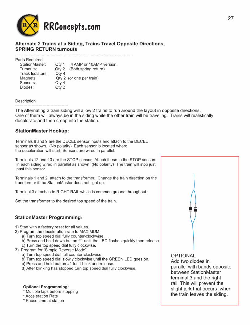
Alternate 2 Trains at a Siding, Trains Travel Opposite Directions, SPRING RETURN turnouts------------------------------------------------------------------------Parts Required: StationMaster: Qty 1 4 AMP or 10AMP version. Turnouts: Qty 2 (Both spring return) Track Isolators: Qty 4 Magnets: Qty 2 (or one per train) Sensors: Qty 4 Diodes: Qty 2
Description---------------------------------------The Alternating 2 train siding will allow 2 trains to run around the layout in opposite directions. One of them will always be in the siding while the other train will be traveling. Trains will realistically decelerate and then creep into the station.
StationMaster Hookup:
Terminals 8 and 9 are the DECEL sensor inputs and attach to the DECELsensor as shown. (No polarity) Each sensor is located where the deceleration will start. Sensors are wired in parallel.
Terminals 12 and 13 are the STOP sensor. Attach these to the STOP sensors in each siding wired in parallel as shown. (No polarity) The train will stop just past this sensor.
Terminals 1 and 2 attach to the transformer. Change the train direction on thetransformer if the StationMaster does not light up.
Terminal 3 attaches to RIGHT RAIL which is common ground throughout.
Set the transformer to the desired top speed of the train.
StationMaster Programming:
1) Start with a factory reset for all values.2) Program the deceleration rate to MAXIMUM. a) Turn top speed dial fully counter-clockwise. b) Press and hold down button #1 until the LED flashes quickly then release. c) Turn the top speed dial fully clockwise.3) Program for “Simple Reverse Mode”. a) Turn top speed dial full counter-clockwise. b) Turn top speed dial slowly clockwise until the GREEN LED goes on. c) Press and hold button #1 for 1 blink and release. d) After blinking has stopped turn top speed dial fully clockwise.
Optional Programming:* Multiple laps before stopping* Acceleration Rate* Pause time at station
RRConcepts.com
OPTIONALAdd two diodes in parallel with bands oppositebetween StationMasterterminal 3 and the rightrail. This will prevent theslight jerk that occurs whenthe train leaves the siding.
28
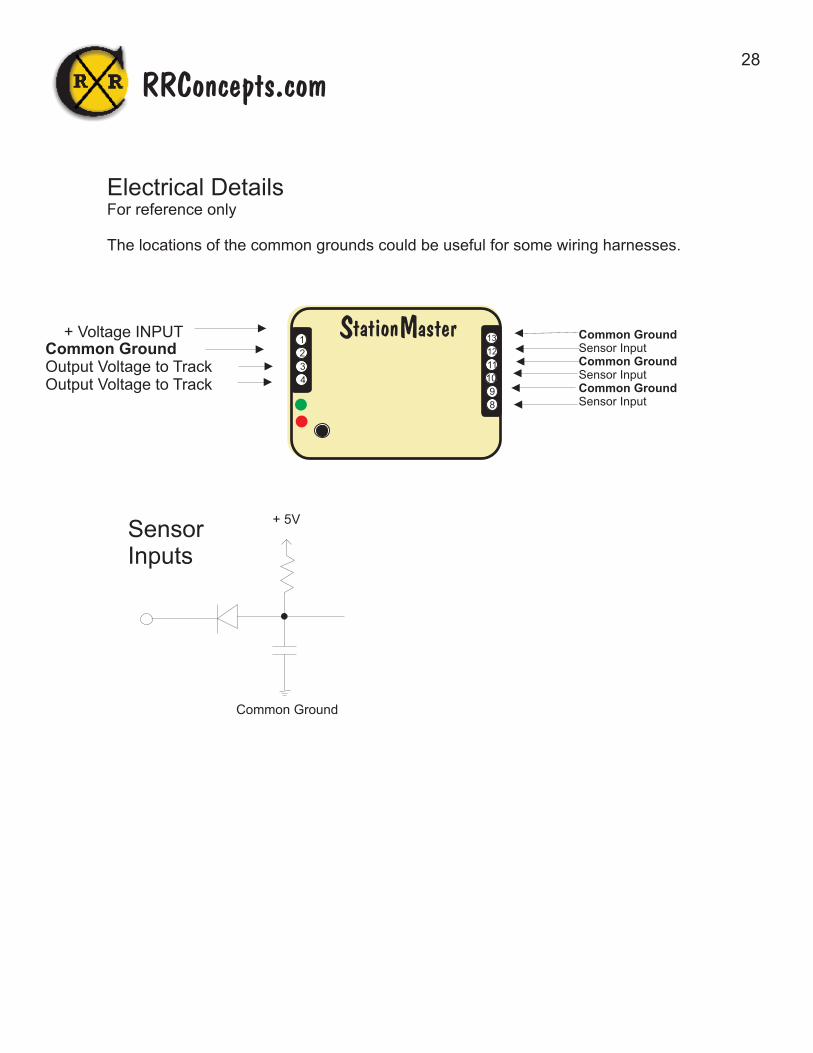
+ Voltage INPUT Common Ground Output Voltage to Track Output Voltage to Track
Sensor Inputs
+ 5V
Common Ground
Electrical DetailsFor reference only
The locations of the common grounds could be useful for some wiring harnesses.
Common GroundSensor InputCommon GroundSensor InputCommon GroundSensor Input
RRConcepts.com
1
2
3
4
8
9
10
11
12
13tation aster S M

29
Sensor Placements on Track
The suggested sensor placement on track is shown below with the train magnet installedin the center of the train. Best sensing is done with the magnet passing over the tip of the sensor.
Sensor Placement for identifying a train.
Offset the train’s magnetto the same side as thesensor as shown.
For example,passenger trains have the magnet offset to the right and freight trainshave the magnet offset to the left side.
Sensor placement for HO EZ track is under the roadbed.
Other scale trains can place the sensors where appropriate. Very small sensors are availablewhich do not have the waterproof housing. These smaller sensors can be used for N, HO, etc. Contact RR Concepts for these sensors.
Your StationMaster is warranted, and guaranteed operational for 1 year. It will be repaired or replaced at no charge within that time period. Contact for additional information.http://www.RR-Concepts.com
WARRANTY
RRConcepts.com