r r rr concepts s m tationaster -...
TRANSCRIPT
CR R
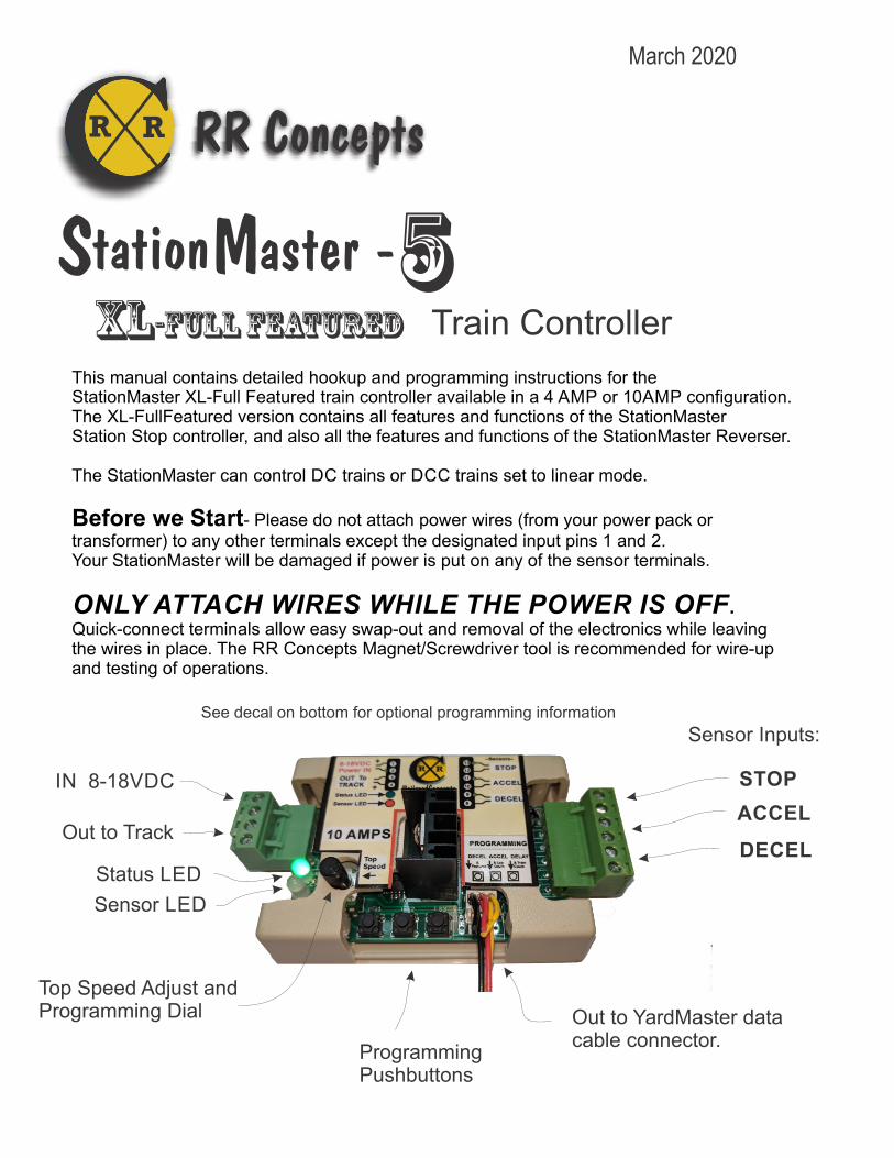
This manual contains detailed hookup and programming instructions for the StationMaster XL-Full Featured train controller available in a 4 AMP or 10AMP configuration. The XL-FullFeatured version contains all features and functions of the StationMaster Station Stop controller, and also all the features and functions of the StationMaster Reverser.
The StationMaster can control DC trains or DCC trains set to linear mode.
Before we Start- Please do not attach power wires (from your power pack or transformer) to any other terminals except the designated input pins 1 and 2.Your StationMaster will be damaged if power is put on any of the sensor terminals.
ONLY ATTACH WIRES WHILE THE POWER IS OFF.Quick-connect terminals allow easy swap-out and removal of the electronics while leavingthe wires in place. The RR Concepts Magnet/Screwdriver tool is recommended for wire-upand testing of operations.
tation aster - XL-Full Featured Train Controller
Status LED
Top Speed Adjust and Programming Dial Out to YardMaster data
cable connector.
IN 8-18VDC
Out to Track
Sensor LED
ProgrammingPushbuttons
Sensor Inputs:
DECEL
ACCEL
STOP
S M
March 2020
5
See decal on bottom for optional programming information
RR Concepts

Status LED
Top Speed Adjust and Programming Dial
“Out to YardMaster” data cable connector for sidingcontrol hookups.
IN 8-18VDC
Out to Track
See the label on the bottom for programming and additional information.
Sensor LED
ProgrammingPushbuttons
Sensor Inputs:
DECEL
ACCEL
STOP
tation aster - Quick Hookup Instructions
RR Concepts
S M 5 How to doRealistic Station Stops & Realisitic Reversing (More details in manual) The StationMaster works with DC (out of the box)or DCC trains set to linear mode. (N, HO, G, etc.) AC trains cannot be controlled.
sensor
Stopping Position
To Power Pack TRACKTerminals
To Power Pack TRACKTerminals
Attach to TRACK.Swap these wires to go theopposite direction
1
2
3
4
8
9
10
11
12
13
StationMaster
Accelerate + Decelerate Station Stop Hookup
1) Attach terminals 1 & 2 to the transformer. 2) Attach terminals 3 & 4 to the track.3) Attach terminals 8 & 9 to a train sensor. (No polarity)4) Mount a magnet on an engine or car.Set the transformer to the desired top speed. That’s it!
See the online manual for optional additional features:* Change acceleration rate, * Change deceleration rate,* Add additional station stops, * Do multiple laps before stopping,* Run 2 trains on the same track. * Change station stop pause duration, (Default 10 seconds)* Perform “Creep-Stop” deceleration for enhanced realism and exact stopping location. (Requires STOP sensor)
Accelerate + Decelerate Reversing Hookup
1) Attach terminals 1 & 2 to the transformer.2) Attach terminals 3 & 4 to the track.3) Program the StationMaster for “Reversing Mode” (see below for programming)
See the online manual for additional in-between stops, self adjusting exact stopping using STOP sensors, delay times, etc,
To TRACK
1
2
3
4
8
9
10
11
12
13
StationMaster
One time programming for No Sensor Reversing mode”: 1. Turn the top speed dial fully counter-clockwise. 4. When train starts to run, press button #3 about2. Simultaneously press buttons 1 and 2. 3 feet from the end. Repeat for both directions.3. Turn the top speed dial fully clockwise. 5. Turn dial to desired creep speed into the ends.
SCAN FOR INFO
10 AMP Version shown, Also available in 4 AMP configuration.
StationMaster CONNECTIONS and CONTROLS
Go to StationMaster.net and download the complete user manual for more info.Visit RailroadConcepts.com for more fun, advanced hookups, and ordering parts.
Un-modified track!No diodes, no breaks, no additional track connections.
Un-modified trains. No sensors, no magnets. It just works!
Reversing Hookup
Station Stop Hookup
CR R

StationMaster Basic Hookup Description
The StationMaster is designed to be installedbetween the train transformer, and the track.
Attach terminals 1 & 2 to your transformer's DC output (Sometimes labeled as TRACK) or to a constant 12 volt power source. If using a train transformer set the throttle position to the desired top speed of the train. If the StationMaster does not "light up", then reverse the direction on the transformer to change the voltage polarity, or swap these two wires.
Attach 3 & 4 to your track. This is the controlled output voltage that accelerates and decelerates the train. Pin 3 will be the “common” wire which is the right rail for Large Scale trains or the left rail for NMRA standard trains.
Terminals 8 & 9 are the start DECEL sensor input.When these terminals are closed (sensor detects a magnet) the StationMaster will begin a decelerate, pause, and then accelerate sequence. The RED “Sensor LED” will light up for as long as this sensor is detected. By placing multiple sensors wired in parallel, the StationMaster can stop at multiple stations on your railroad.
Pressing button #1 will simulate the DECEL sensor operation.
DECEL Sensor
+-
Left
Right
CR R RR Concepts

Terminals 10 and 11 are the optional Start Acceleration sensor inputs.
When these terminals are shorted (sensor detects a magnet) the train will start to accelerate.
This sensor is not necessary unless using “Block Control” or the time delay is set for maximum blinks. (See below).
Pressing button #2 will simulate the ACCEL sensor.
When programmed for “Blink1: Simple reversing mode” this sensor will perform anin-between station stop and the ACCEL function will not be operational.
Terminals 12 and 13 are the optional STOP sensor inputs.
ACCEL Sensor
STOP Sensor
When the train is decelerating and these terminals are shorted (sensor detects a magnet), the train will immediately STOP. This sensor is not necessary unless using the “Creep-stop” mode in which caseit is mandatory. The STOP sensor will have no affect unless the train has already passed over the DECEL sensor.
Pressing button #3 will simulate the STOP sensor.
Optional
CR R RR Concepts

Top Speed and Programming Mode Dial
The Top Speed dial provides 3 functions:
1: Adjust the top "cruising" speed of the train. 2: Enter programming mode. 3. Reduce the “creep speed” when in No Sensor Reversing mode.
Top speed adjustment“Full speed" is clockwise. Turn this dial down as necessary to set the desired cruising speed of the train. This is only necessary when using a “fixed voltage” power supplyor when a YardMaster is attached and a slower top speed is desired.
Typically, this dial is set fully clockwise and the train throttle (transformer) is used to set the speed of the train.
Programming ModeTo enter programming mode turn this dial fully counter-clockwise. The Sensor LED will display orange to indicate “programming mode”.
The acceleration rate, deceleration rate and time delay can be programmed in this state.See the programming details or decal on bottom of the StationMaster for additional information.
To exit programming mode turn the dial fully clockwise.
No Sensor Reversing Mode Creep SpeedWhen in No Sensor Reversing mode this dial can be used to reduce the creeping speedinto the diode sections. Turn the dial counter-clockwise to decrease the speed.
CR R RR Concepts

Green flashing: train is ACCELERATING.
Green flashing with green solid: Train is creeping out of station. After a delaythe train will continue to accelerate up to top speed.
Both flashing green is a dead man timer shutdown. See details later in this manual. No train has been detected for several minutes.
Green NOT flashing: Train is AT TOP CRUISING SPEED.
1. Orange NOT flashing, The StationMaster will ignore next DECEL sensor due to lap counting or block control.
2. Orange Flashing, The StationMaster is performing a time delay.
1. Quick Red flashing: Train is DECELERATING. Flash rate indicates the rate of deceleration.
2. Two quick RED flashes at 1 second rate: StationMaster is waiting for the ACCEL sensor before accelerating. (StationMaster Is programmed for infinite time delay)
Sensor RED LED ON or flash: The STOP sensor is detected.The LED will remain on for as long as the sensor is detected. If a train is parked on the STOP sensor then the deceleration sensor will be ignored.
Two Red Blinking LED's indicate a SHORT CIRCUIT condition. To recoverturn the top speed dial to zero and then back to 100%, push button 1, or cyclepower. If condition returns after recovery check for a short circuiton the track or re-program the shutdown threshold. (See AUTOMATIC SHUTDOWNDETAILS later in this manual) When flashing, press button #3 to reset shutdown value.
Sensor LED GREEN or flickering indicates secondary Programming mode.
Sensor LED orange flickering: Indicates programming mode. The top speed dial is fullcounter-clockwise.
STATUS LED
STATUS LED
STATUS LED
STATUS LED
STATUS LED
STATUS LED
STATUS LED
STATUS LED
STATUS LED
STATUS LED
SENSOR LED
SENSOR LED
SENSOR LED
SENSOR LED
SENSOR LED
SENSOR LED
SENSOR LED
SENSOR LED
SENSOR LED
SENSOR LED
LED indicatorsFor Information only
CR R RR Concepts

Programming: Deceleration Rate
Fullycounterclockwise
CR R RR Concepts
1. Make sure all three sensor inputs are open.
2. If the top speed dial is not already at zero, then turn the top speed dial to zero. (fully counter-clockwise.) The Blue “Train Detected” LED will “twinkle”
3. Push and hold programming button #1.
4. Watch the status led. Each RED blink will decelerate slower.
The fastest deceleration will be with one blink. (TRAIN Stops sooner) Release the pushbutton when the desired number of blinks have occurred. A typical number is 5. Repeat this procedure if you want a different value.
One blink corresponds to a 3 second deceleration rate. Each additional blink adds 1 second. For example, a blink count of 5 would result in a deceleration rate of8 seconds.
When finished with all programming turn the top speed dial fully clockwise and then turn down to a desired top speed if needed.
All programming values are stored in flash memory and are retained until re-programmed.

Programming: Acceleration Rate
Fullycounterclockwise
CR R RR Concepts
1. Make sure all three sensor inputs are open. (Red LED is off)
2. If the top speed dial is not already at zero, then turn the top speed dial to zero. (fully counter-clockwise.) BlueTrain Detected LED will “twinkle”.
3. Press and hold programming button #2..
4. Watch the status led. Each GREEN flash will accelerate slower.
The fastest acceleration will be with one blink.Release the button when the desired number of blinks have occurred. A typical number is 5. Repeat this procedure if you want a different value. One blink corresponds to a 3 second acceleration time. Each additional blink adds 1 second. For example, a blink count of 5 would result in a deceleration rate of8 seconds. A factory default will set to 5.
When finished with all programming, increase the top speed dial clockwise to MAX and then down to a desired top speed. All programming values are stored in flash memory and are retained until re-programmed.
A Note on Realistic Accelerations:
* For blinks 1 thru 9 the train will accelerate linearly with the programmed value. This may be required for some block control operations where a second train is approaching and the first train needs to quickly accelerate to get out of the way, or for a trolley which accelerates quickly.
* For blinks 10 and above the train will creep very slowly out of the station and then continue accelerating as it continues down the main line. This provides a very realistic operation as a train creeps out of a siding or station and shows off sound systems with incredible realism.
* 10 blinks will creep for 5 seconds.* 11 blinks will creep for 10 seconds.* 12 blinks and up will creep for 15 seconds.

1. Make sure all three sensor inputs are open. (red Led is off)
2. If the top speed dial is not already at zero, then turn the top speed dial to zero. (fully counter-clockwise.) All LED'S will turn off.
3. Press and hold programming button #3.
4. Each ORANGE flash will increase the waiting time after a station stop.
A wait time of zero will be with one flash. Release the button when the desired number of flashes have occurred. Repeat this procedure if you want a different value. The LED will turn orange when an infinite delay is set (after 10 counts).
When infinite delay is set, then the ACCEL sensor is required to start up the train
after a station stop. A fun thing to do would be to connect the ACCEL terminals to a doorbell switch. Your train would patiently wait until someone pushed the button! Motion
sensors are another possible way to start the train.
When finished with all programming increase the top speed dial clockwise to maximum or to a desired top speed. All programming values are stored in flash memory and are retained until re-programmed.
Programming: Pause Time
Fullycounterclockwise
The number of orange FLASHES will correspond to the following time delays:
1: 0 seconds, no wait. 2: 5 seconds 3: 10 seconds 4 15 seconds 5: 20 seconds 6: 30 seconds 7: 1 minute 8: 2 minutes 9: 5 minutes10: 10 minutes11: 30 minutes12: 60 minutes13: Infinite, wait for GO sensor. This is for block control operations.
CR R RR Concepts

HOW TO PROGRAM: (Perform a factory reset to clear everything)
1. Enter Secondary Programming mode: (Skip this step if already in secondary programming mode)
* Turn the Top Speed dial fully counter-clockwise to enter programming mode (Skip this step if already in programming mode).
* Turn the Top Speed dial slowly clockwise until the sensor LED turns green. This indicates secondary programming mode. This should be about half-way.
2. Press and hold programming button #1 until the desired number of blinks have occurred.Each blink will set or clear a different feature. If currently ON it will turn off. If ON it will turn OFF.
When finished do not power off without first turning the dial fully clockwise.
Programmable Modes: (Any or all of these or all can be programmed independently)
Hold button for 1 blink = Simple Reversing Mode, ignore next sensor after reversing, ACCEL sensor will perform an in-between station stop.
Hold button for 2 blinks = Fire YardMaster before acceleration. (Default ON in reversing mode)
Hold button for 3 blinks = Fire YardMaster after train has stopped. (Set after factory reset)
Hold button for 4 blinks = Use automatic train detection to start deceleration. (No-sensor station stops)
Hold button for 5 blinks = Reverse direction before every acceleration. Never ignore sensors.
Hold button for 6 blinks = Only fire YardMaster in forward direction. (For reversing operations with a siding on one end)
Hold button for 7 blinks = Shut off current sensor. This could cause damage to the StationMaster unless the transformer can provide short-circuit shutdown. This is sometimes necessary when running with very small transformers. (1 AMP or less)
Hold button for 8 blinks = Turn on “creep stop”. The train will decelerate then creep until reaching the STOP sensor. LEDs will flash RED/GREEN when creeping. When the button is released the StationMaster will echo the currently programmed features (modes)by blinking the red/green LED 8 times. For example, if “Fire YardMaster after train has stopped” hasbeen programmed (button pressed for 3 blinks, or after factory reset) and nothing else is programmed then the StationMaster will blink: blink 1 RED: Reversing mode is OFF. blink 2 RED: Fire YardMaster before acceleration OFF blink 3 GREEN: Fire YardMaster after stopping ON blink 4 RED: Use train sensor to start deceleration OFF blink 5 RED: Reverse direction before every acceleration OFF blink 6 RED: Only fire YardMaster in forward direction OFF blink 7 RED: Disable current sensor: OFF blink 8 RED: Creep-stop mode : OFFEach time a feature is programmed that feature will toggle on or off. (Toggle means the feature will go OFF if currently ON, or ON if currently OFF). A factory reset will clear all values and set blink 3.
To view the currently programmed operating modes quickly press and release button #1.
Programming: Operating Modes
Please go to RRconcepts.com to view an informational video on how to program operating modes.
Green
CR R RR Concepts

Additional Information on Programming Modes. The hookup diagrams will identifywhich of these need to be set.
blink 1 = Simple Reversing Mode
This will allow reversing operations with a DECEL sensor placed at the ends wired in parallel. After reversing the very next DECEL sensor will be ignored. In-between station stops can be done by adding sensors in parallel to the ACCEL terminals. The train will stop at every location where a sensor is placed. the ACCEL sensor operation will not be operational.
blink 2 = Fire YardMaster before acceleration. If programmed for more than 1 train the YardMaster will fire to the next siding after before accelerating
blink 3 = Fire the YardMaster after the train has stopped.
If programmed for more than 1 train the YardMaster will fire to the next siding after the train has stopped. Note that the StationMaster will automatically set this blink after a factory reset.
blink 4 = Use automatic train detection to start deceleration.
When a train is sensed entering the track section the StationMaster will start a deceleration sequence.
blink 5 = Reverse direction before every acceleration
This is similar to blink 1 however the StationMaster will not ignore any sensors and the ACCEL sensor will be operational.
blink 6 = Only fire YardMaster in forward direction. (only active in reversing mode)
This will allow a reversing operation with sidings on one end.
blink 7 = Disable current sense shutdown.
If a double RED blinking shutdown condition occurs too often then the power supply may be too small to provide sufficient current and is not reliably sensed by the StationMaster. The shutdown can be disabled however damage could occur if the transformer does not have short-circuit protection.
blink 8 = Turn on “CREEP STOP” mode.
The train will decelerate using the programmed deceleration rate, then creep until reaching the STOP sensor. If the STOP sensor is not reached within 25 seconds then the creep speed is increased for next time. This creates incredible realism for you trains. .
CR R RR Concepts

Programming: Factory Reset
To set the StationMaster back to factory defaults perform the following:
1: Enter programming mode by turning the top speed dial fully counter-clockwise2. Press and hold both button #1 and button #3, then release. 3. Save the settings by turning the top speed dial fully clockwise to exit programming mode.
Do not power off without first turning the dial fully clockwise.
The factory default settings are:
* Acceleration rate 5 blinks* Deceleration rate 3 blinks.* Time delay 5 seconds.* Train count: 2 (Note: Block control will not be operation until set for 1 train)* Lap count: 1* Operating mode (features):
Blink 1 = RED, Simple Reversing: OFF. Blink 2 = RED, Fire YardMaster before accelerating: OFF Blink 3 = GREEN, Fire YardMaster after train has stopped: ON Blink 4 = RED, Use train sense to start deceleration: OFF Blink 5 = RED, Reverse before every acceleration: OFF Blink 6 = RED, Fire YardMaster only in forward direction: OFF Blink 7 = RED, Disable current sensor: OFF Blink 8 = RED, Enable CREEP-STOP mode: OFF
Fullycounterclockwise
With these settings both the Simple Station Stop, and the Alternating Trains hookups are ready to run!
CR R RR Concepts

1. Turn the Top Speed dial fully counter-clockwise to enter programming mode(Skip this step if already in programming mode).
2. Slowly turn the Top Speed dial clockwise until the GREEN indicator turns on. This indicates secondary programming mode. (Skip this step if already in secondary programming mode)
3. Press and hold button #2.
4. Count the blinks while the button is pressed. Release the button when theappropriate number of blinks (LAPS) are set.
When finished with all programming turn the top speed dial clockwise to maximum.
All programming values are stored in flash memory and saved until re-programmed again.
Programming: MULTIPLE LAPS
Green
CR R RR Concepts
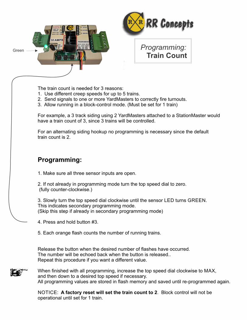
The train count is needed for 3 reasons:1. Use different creep speeds for up to 5 trains.2. Send signals to one or more YardMasters to correctly fire turnouts.3. Allow running in a block-control mode. (Must be set for 1 train)
For example, a 3 track siding using 2 YardMasters attached to a StationMaster wouldhave a train count of 3, since 3 trains will be controlled.
For an alternating siding hookup no programming is necessary since the defaulttrain count is 2.
Programming:
1. Make sure all three sensor inputs are open.
2. If not already in programming mode turn the top speed dial to zero. (fully counter-clockwise.)
3. Slowly turn the top speed dial clockwise until the sensor LED turns GREEN.This indicates secondary programming mode. (Skip this step if already in secondary programming mode)
4. Press and hold button #3.
5. Each orange flash counts the number of running trains.
Release the button when the desired number of flashes have occurred. The number will be echoed back when the button is released.. Repeat this procedure if you want a different value. When finished with all programming, increase the top speed dial clockwise to MAX, and then down to a desired top speed if necessary. All programming values are stored in flash memory and saved until re-programmed again.
NOTICE: A factory reset will set the train count to 2. Block control will not be operational until set for 1 train.
Programming: Train Count
Green
CR R RR Concepts

“Creep-Stop” Deceleration for Incredible Realism
A unique and extremely realistic feature of the StationMaster is “Creep-Stop” Deceleration. By using both a DECEL sensor and a STOP sensor the StationMaster will provide a very realistic station stop.Programming your StationMaster to use “Creep-Stop” is very easy:
1. Set bit 8 in programming mode.(Press and hold button #1 in SECONDARY Programming mode until the LED blinks rapidly)2. Place the DECEL and STOP sensors on your track as shown. The distance between sensors should be about 2 to 6 feet, or whatever looks good to you. 3. Program the deceleration rate (if needed) to provide a realistic deceleration into the train yard before the creep starts.
When “Creep Stop” is enabled, the train will decelerate using the programmed deceleration rate, then “creep”forward until the STOP sensor is reached. This guarantees the train will always stop on the STOP sensor usinga realistic profile. The starting creep speed is relatively slow however the train mustreach the STOP sensor within 25 seconds. If the train stalls, then the creep speed is increased for the next time.When a stall occurs, the voltage will be increased to allow the train to reach the STOP sensor after 25 seconds.Be patient. If the train stalls it will eventually carry on.
The length of the creeping can be adjusted by either increasing or decreasing the distance between DECEL and STOP sensors, increasing or decreasing the deceleration rate, or both. Start with a 4 foot distance and seehow that looks.
Up to 5 different creep speeds can be used for 5 different trains. Slow trains can run next to fast trainsand each will creep perfectly, Use the “train count” to set the number of trains that will be run. A factory default willset for 2 trains which is perfect for an alternating siding setup.
STOP sensor DECEL sensor
To Power Pack TRACKTerminals
Attach to TRACK
+-
That’s it!
liaR thgiR
1
2
3
4
8
9
10
11
12
13
StationMaster
15
CR R RR Concepts

“Justa Station Stop”
Justa-Station-stop performs a decelerate/Pause/Accelerate sequence withouttriggering an attached YardMaster or reversing.
When operating in an alternating trains setup additional stations stops can be done at different locations around the loop without affecting the parked train.
Place a STOP and a DECEL sensor such that they are both triggered at the same time.The train will decelerate, pause and accelerate without triggering a YardMaster and withoutchanging directions.
If self-adjusting mode is programmed then the deceleration rate will be fixed. Otherwisethe programmed deceleration rate will be used.
STOP Sensor
DECEL Sensor
Train Direction
1
2
3
4
8
9
10
11
12
13
StationMaster
CR R RR Concepts

DECEL sensor
Stopping Position
To Power Pack TRACKTerminals
Attach to TRACK
Basic Hookup Diagram forAutomatic Station Stops with Deceleration/Accelerationusing train sensors.
To Left Rail
Place MAGNETon bottom of engine.
Add additional sensors in PARALLEL for additional station stops.
For a simple station stop, this is all you need to do!Factory settings will be a gradual acceleration, gradual deceleration and 10 second stop.
1
2
3
4
8
9
10
11
12
13
StationMaster
Swap wiresto go opposite direction
CR R RR Concepts

+
-
To Power Pack TRACKTerminals
Attach to TRACK
Multiple Station Stops
Your train can stop at many stationson the loop by adding DECELsensors in parallel.
Every sensor that the train passes over will cause a declerate/pause/acceleratesequence.
1
2
3
4
8
9
10
11
12
13
StationMaster
CR R RR Concepts

ACCEL sensor
DECEL sensor
To Power Pack TRACKTerminalsor fullspeed track.
Isolators
Isolated Block
For 1 or 2 Trains on 1 track with gradual Decelerations and Accelerations.Can be located at a remote location on the railroad
Block Control
+
+
-
Programming:* Train count: 1* Time delay: maximum
When ORANGE is displayedthe next DECEL sensor willbe ignored. This preventsa train from stopping if thefollowing trains is too close.This also allows 1 train to be run on the track without stopping.Hitting ACCEL without a train inthe block will set this.
1
2
3
4
8
9
10
11
12
13
StationMaster
Hookup Notes:1. Your train may not stop if the second train is too close. (ACCEL is hit before DECEL)2. When the train decelerates it must stop before reaching the 2nd isolator..3. If the train is slowing or stopped, then the second train will tell it to “go” when it hits the ACCEL sensor. (Start with sensor half-way around the track. Station stop will be longer with ACCEL sensor closer.) Move the location of this sensor to fit your track.5. Location of ACCEL sensor must allow the stopped train time to accelerate and exit before the 2nd train enters the siding.6. This hookup can run with 1 train or 2 trains. (1 train will never stop unless ACCEL sensor is removed)7. A longer isolated section will provide more realism for the stopped train to decelerate and accelerate.8. Station can be located at a remote location on your railroad.
To Power Pack TRACKTerminals. Left rail ispositive. Switch direction if StationMaster does not light up.
TIP:The location of the ACCEL sensor determineshow long a train will wait at the block:.* When closer to the block the pause will be longer.* When farther away both trains will run for a longer amount of time.
CR R RR Concepts

ACCEL sensor
DECEL sensor
To Power Pack TRACKTerminals
To Power Pack TRACKTerminals
Isolators
+
+
-
Programming:* Train count: 1* Time delay: maximum
When ORANGE is displayedthe next DECEL sensor willbe ignored. This preventsa train from stopping if thefollowing trains is too close.This also allows 1 train to be run on the track without stopping.Hitting ACCEL without a train inthe block will set this.
ACCEL sensor
DECEL sensor
To Power Pack TRACKTerminals
Isolators
+-
For 1, 2, or 3 Trains on 1 track with gradual Decelerations and Accelerations using StationMasters.
Block Control
1
2
3
4
8
9
10
11
12
13
StationMaster
1
2
3
4
8
9
10
11
12
13
StationMasterCR R RR Concepts

To Power Pack TRACKTerminals
To Power Pack TRACKTerminals
Using the Automatic Train Detection feature.
No Sensor Station Stop
+
+
-
-
To L
eft R
ail
Hookup Notes:1. Isolated section must be long enough to allow train to decelerate and accelerate.2. Train can only go in one direction.3. Protection diode prevents damage in case of train running backwards.4. Program StationMaster for “blink 4”.5. Program time delay as desired.6. No magnets and no sensors are required7. Station stop can be located at a remote location on your railroad far from the transformer.
Programming:* Operational mode: blink 4
Isolators
Protection Diode
1
2
3
4
8
9
10
11
12
13
StationMaster
CR R RR Concepts
Isolated Block

HOOKUP:1 2 To Power Pack DC TRACK Terminals. If StationMaster does not turn on then reverse direction on the transformer.
3 4 To Track
8 9 To DECEL sensors wired in parallel.
12 13 To STOP sensors wired in parallel.
See next page for optional in-between station stops.
To TRACK
Sensors in PARALLEL.
Extremely Realistic Reversing Operations
When programming Mode blink 1 is set the StationMaster will go into reversing mode.
Sensors are placed near the ends to signal the StationMaster to begin the deceleration / pause / accelerate operation. Sensors on the ends stop the train at an exactlocation. Sensors have no polarity. Place sensors about 2 feet apart for realistic operation.Set the StatioMaster for “Creep-Stop” mode, and program the acceleration and deceleration as desired.
Terminals 8 & 9
Terminals 12 & 13
1
2
3
4
8
9
10
11
12
13
StationMaster
STOP
START DECELERATION
MAGNET on train
CR R RR Concepts

Extremely Realistic Reversing Operations with In-Between stops
(See the previous page for wiring the reversing operation)When running in a back-and-forth reversing operation In-Between station stops are doneby placing pairs of ACCEL sensors on the track. When the StationMaster detects an ACCEL sensor it will perform a “Justa-Station-Stop operation”. The ACCEL sensor input will not performan acceleration operation when programmed for simple reversing mode (Blink 1)
ACCEL sensors in PARALLEL
Terminals 10 11
NOTES:1. The train magnet must stop between the pair of sensors. This will allow the train to stop at the same location from either direction. When the train accelerates it will ignore the very next sensor that it passes over so it must stop before reaching the 2nd sensor. One sensor can be used for a single in-between stop however the train will stop at a different location for each direction. (It will decelerate and stop after passing over the sensor)
2. Sensors have no polarity.
3. Additional station stops can be done by adding additional pairs of sensors, all wired in parallel. There is no limit to the number of stops that can be done..
1
2
3
4
8
9
10
11
12
13
StationMaster
CR R RR Concepts

To Power Pack DC TRACKTerminals.If StationMaster does not turn onthen reverse direction on transformer.
To TRACK
Diode Isolators (two places)
No Sensor Reversing Hookup The StationMaster-5 XL includes all the features of the StationMaster/Reverser when enabled. This includes the “No-Sensor Diode Reversing Mode” where diodes are placed at the ends to stopthe train. ( If desirable, LGB 10151 units can be use in place of diodes.)
PROGRAMMING:
1. Go to programming mode. (Turn the speed dial full counter-clockwise)2. Press buttons #1 and #2 at the same time.3. Exit programming mode. (Turn the speed dial full clockwise) - To return to normal operations perform a factory reset -
Reversing using Diodes
1
Diodes can be wired to the track using self-tapping screws or attached to an isolator.A 1 or 2 AMP diode is usually sufficient.
continued...
1
2
3
4
8
9
10
11
12
13
StationMaster
Here is the hookup: * 2 wires from the transformer to the StationMaster. * 2 wires from the StationMaster to the track. * Diodes on the ends where the engine will stop.
24
CR R RR Concepts

Reversing Operations - No Sensors Continued...
Pushbutton Operations
Button 1:Reset TIMETO DECELERATEfor this direction. (start over)
Button #2: - optional - Terminate the time delay operationand reverse as soon as possible.(Convenience during programming)
Button #3:Start deceleration NOW.
CR R RR Concepts
OPERATIONS:
The Reverser has a 2 step speed profile. Speed #1 is the top speed of the train set by the transformer. Speed #2 is a “creeping” speed which allows the train to always reach the diode isolators on the ends. The Reverser will accelerate using the programmed acceleration rate, maintain a top speed, and then decelerate down to Speed #2 when the TIME TO DECELERATE time is reached.
Once the deceleration has completed, Speed #2 will be maintained for the duration of the “pause time”. This provides a very realistic and smooth operation. After a reverse, the operation is repeated.
Do This Once:
1 Set the transformer for the desired top speed of the train. Turn the StationMaster top speed dial fully clockwise.
2 Watch the train and press BUTTON #3 when the train reaches the TIME TO DECELERATE location. This is typically 3 feet from the ends, but depends on the speed of the train and the programmed deceleration rate. The train will blink red and decelerate. After decelerating, the Reverser will blink RED/GREEN while the train creeps into the stops. After reversing, repeat for the other direction. Notice that the Reverser will store different TIME TO DECELERATE values for each direction since trains don’t always go the same speed in forward and reverse. This will need to be done THREE times after reversing.
3 To erase stored time values: Press programming buttons #1 and #2 at the same time . Note that this is not always necessary since the TIME TO DECELERATE can be changed at any time by pressing buttons #1 (clear) or #3(SET) for the current direction. (see below,)
That’s it!
Dial: - optional - Turn counter-clockwise
to creep slower.Note: Turning too far will enter programming mode.
.
Continued...

Reversing Operations - No Sensors Continued...Reversing Operations - No Sensors Continued...
Notes
LED Indications
This LED will:Flash GREEN when accelerating,Flash RED when decelerating,Slowly flash GREEN/RED during the time delay.Blink ORANGE when an infinite time delay is running.(When in this condition button #2 MUST be pressed to continue.)
This LED will:Turn RED when a TIME TO DECELERATEvalue is NOT set for this direction. Button #3 MUSTbe pressed to set the deceleration time or the train will never reverse.
Pushbutton and Dial Operations - a few more details
All recorded values are stored in flash memory and retained after a power cycle. For consistentoperation day after day the transformer throttle setting should be the same. Sometimes trainswill run a different speed after operating for awhile, and this is expected. To always creep into the ends set the TIME TO DECELERATE location sooner to allow more creep time.
The duration of the creep time comes from the programmed delay time. The delay time is actually“wait this long before reversing”. If a very long creep is done, then the pause at the ends will beshorter. Increase the time delay if a longer pause time at the ends is desired.
When the Reverser is running, button #3 can be pressed at any time to set the TIME TODECELERATE. When pressed, the deceleration will start and this time is recorded. If the deceleration is starting too soon and a different time is desired, then pressBUTTON #1 to erase the stored value. This will cause the Reverser to set an infinite time delay to allow the train to creep into the stops (orange blink). Once the train enters the stops, press button #2 (terminate the time delay) to continue. Set the TIME TO DECEL again afterthe train reverses and comes back in this direction.
The default creep speed is relative to the transformer throttle setting. If a slower creep speed is desired, then turn the top speed dial counter-clockwise to slow the train down. Note that the creep speed will be the same for both directions. Some trains will creep faster in forward thanin reverse. Note that the StationMaster requires at least 8 volts to operate.
Most important- Always allow the trains to enter the stops on the ends before setting theTIME TO DECELERATE value (button #3). We need to record the time to start the decelerationfor the full length of track.
T
CR R RR Concepts

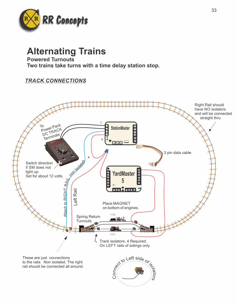
Place MAGNETon bottom of engines.
Track isolators, 4 Required. On LEFT rails of sidings only.
+-
1
4
To
Power Pack
DC TRACK
Terminals
Switch directionif SM does notlight up.Set for about 12 volts.
Right Rail shouldhave NO isolators and will be connected straight thru
These are just connectionsto the rails. Non isolated. The rightrail should be connected all around.
1
2
3
4
8
9
10
11
12
13
StationMaster 5
Spring ReturnTurnouts
If powered turnoutsare necessary usethe YardMaster hookup
Programmed forSimple Reversemode
TRACK CONNECTIONS
Note band on diodes,they are on opposite ends.
lia
R tfe
L
Seenote foradding optionaldiodes on following pages.
CR R RR Concepts
Alternating Trains in Opposite DirectionsSPRING-RETURN TURNOUTS

1
2
3
4
8
9
10
11
12
13
StationMaster
8
9
13
12
ST
OP
senso
rs in P
AR
AL
LE
L
SENSOR CONNECTIONS
For additional station stops around the loopsee“Justa-Station-Stop”in the StationMastermanual.
Program for Simple Reversing Mode
CR R RR Concepts
Alternating Trains in Opposite DirectionsSPRING-RETURN TURNOUTS

Alternating Trains in Opposite DirectionsMore details...------------------------------------------------------------------------Parts Required: StationMaster: Qty 1 4 AMP or 10AMP version. Turnouts: Qty 2 (Both spring return) Track Isolators: Qty 4 Magnets: Qty 2 (or one per train) Sensors: Qty 4 Diodes: Qty 2
Description---------------------------------------The Alternating 2 train siding will allow 2 trains to run around the layout in opposite directions. One of them will always be in the siding while the other train will be traveling. Trains will realistically decelerate and then creep into the station.
StationMaster Hookup:
Terminals 8 and 9 are the DECEL sensor inputs and attach to the DECELsensor as shown. (No polarity) Each sensor is located where the deceleration will start. Sensors are wired in parallel.
Terminals 12 and 13 are the STOP sensor. Attach these to the STOP sensors in each siding wired in parallel as shown. (No polarity) The train will stop just past this sensor.
Terminals 1 and 2 attach to the transformer. Change the train direction on thetransformer if the StationMaster does not light up.
Terminal 3 attaches to RIGHT RAIL which is common ground throughout.
Set the transformer to the desired top speed of the train.
OPTIONALAdd two diodes in parallel with bands oppositebetween StationMasterterminal 3 and the rightrail. This will prevent theslight jerk that occurs whenthe train leaves the siding.
CR R RR Concepts
StationMaster Programming:
1) Start with a factory reset for all values2) Program for “Simple Reverse Mode” and “Creep Stop” a) Turn top speed dial full counter-clockwise. b) Turn top speed dial slowly clockwise until the GREEN LED goes on. c) Press and hold button #1 for 1 blink and release. d) After blinking has stopped press and hold button #1 for 8 blinks. d) Turn top speed dial fully clockwise.
Optional Programming:* Add Multiple laps before stopping.* Change the Acceleration Rate.* Change the Pause time at the station.* Change the Deceleration rate so trains always go to the creep state.

1
2
3
4
8
9
10
11
12
13
StationMaster
8
15
16
9
13
12
STO P sensor
Station Stop with a Siding 11
2
3
4
5
6
20
19
18
17
16
15
7 118 129 13 14
YardMaster 5
After a few laps on the main line, go into the siding and stop.
Second turnout canbe wire in parallelor floating.
OPERATIONS* While counting laps, the YardMaster will fire to RED each time the DECEL sensor is ran over.* After the lap counting has finished, the YardMaster will fire to GREEN on the DECEL sensor and the train will stop in the siding.
3 pin data cable
To Turnout
DECEL sensor
Set for 10 to 18 volts and useTop speed dial to set train speed
== Parts List ==1 StationMaster-51 YardMaster-52 Train sensors1 magnet1 three pin data cable
CR R RR Concepts30
PROGRAMMING:1. Turn on blinks 2 and 3 in “features” programming. (3 is set by default after a factory reset)2. Program a lap count greater than 1.3. Turn on “Creep stop” in “features” programming OR set a deceleration rate such that the train reaches the STOP sensor.

Automatic Shutdown Details
The StationMaster has advanced electronics and software which will attempt to protect itself and also your trains when potentially disastrous events occur.
The first level of defense will provide a shutdown when a short circuits occurs due to a train wreck or wring problem. Typically transformers know their current capability and willshut down when a current threshold is reached. For sensitive electronics this is sometimestoo late. The only way for the StationMaster to determine a short circuit is to measure the current before that happens and record this value. When that value is reached theStationMaster will shut down and blink both RED LEDs.
HOW TO SET THE SHUTDOWN THRESHOLD
Since this is such an important feature, there have been many software variations, each onebetter than before. Your StationMaster may have either of the following :
Version 1: The shutdown threshold is set after exiting programming mode. Make sure the train transformer is set to 100% when exiting programming mode. The relays will click.
Version 2: (Current as of 11/2019) The shutdown threshold is set after a factory reset, and then exiting programming mode and also by pressing button #3 when the red blinking is occurring. In both cases, make sure the transformer is set to 100% when the relays click.
SMALL TRANSFORMER OVERRIDE
For small transformers it may not be possible to obtain a shutdown value, since the transformer could be operating at 100%. In this case the red blinking will occur frequently and the “No Shutdown” option must be programmed. Small transformers will be lessthan 2AMPS or 30VA. It is unlikely the StationMaster will be damaged with a short circuitof 2 AMPS or less, and the transformer will likely shut down.
CR R RR Concepts

StationMaster “Deadman Timer”
A unique feature of the StationMaster is the DeadmanTimer.If a train is sensed on the track and no sensor has beendetected for 10 minutes, the StationMaster will SHUT DOWNand flash both green LEDs.
This prevents the condition where a train is hung up on anobstruction and spinning it’s wheels, most probably grinding a divot in the rails and wearing out wheels and gears.
Each time a sensor is triggered, or the train is not sensed, the deadman10 minute timer is reset.
The Deadman Timer will be enabled AFTER the first sensor or pushbutton is pressed after power up.
How to use or bypass the Deadman Timer Shutdown:
* When the sensor connector is pulled and trains are running “manually”, the Deadman Shutdown will not be enabled, unless a button is pushed.
* To run “manually” and also use the Deadman Shutdown, the DECEL sensor needs to be pulled, and either the STOP or ACCEL sensor must be run over.
Flashing Green LEDs
SensorConnector
32
CR R RR Concepts
Place MAGNETon bottom of engines.
Track isolators, 4 Required. On LEFT rails of sidings only.
+-
1
4
To
Power Pack
DC TRACK
Terminals
Switch directionif SM does notlight up.Set for about 12 volts.
Right Rail shouldhave NO isolators and will be connected straight thru
These are just connectionsto the rails. Non isolated. The rightrail should be connected all around.
1
2
3
4
8
9
10
11
12
13
StationMaster
Spring ReturnTurnouts
Alternating Trains Powered TurnoutsTwo trains take turns with a time delay station stop.
TRACK CONNECTIONSli
aR tf
eL
11
2
3
4
5
6
20
19
18
17
16
15
7 118 129 13 14
YardMaster 5
CR R RR Concepts
3 pin data cable
33

1
2
3
4
8
9
10
11
12
13
StationMaster
8
15
16
9
13
12
STO P sensor
11
2
3
4
5
6
20
19
18
17
16
15
7 118 129 13 14
YardMaster 5
Second turnout canbe wired in parallelor floating.
Stop sensors wired in parallel,one in each siding. No polarity.
To Turnout
DECEL sensor
Alternating Trains Powered Turnouts
SENSOR CONNECTIONS
CR R RR Concepts
PROGRAMMING:1. This is the default operation after a factory reset.2. Turn on optional “Creep Stop” for more realism so the trains creep to the STOP sensor.3. Set an optional lap count if desired.4. Set a longer acceleration rate if desired to creep out of the station.
OPERATIONS* Two trains will take turns running on the loop using an optional lap count. When the train has stoppedthe next train will run after the time delay.
34

+ Voltage INPUT Common Ground Output Voltage to Track Output Voltage to Track
Sensor Inputs
+ 5V
Common Ground
Electrical DetailsFor reference only
The locations of the common grounds could be useful for some wiring harnesses.
Common GroundSensor InputCommon GroundSensor InputCommon GroundSensor Input
1
2
3
4
8
9
10
11
12
13tation aster S M
CR R RR Concepts
Sensor Placements on Track
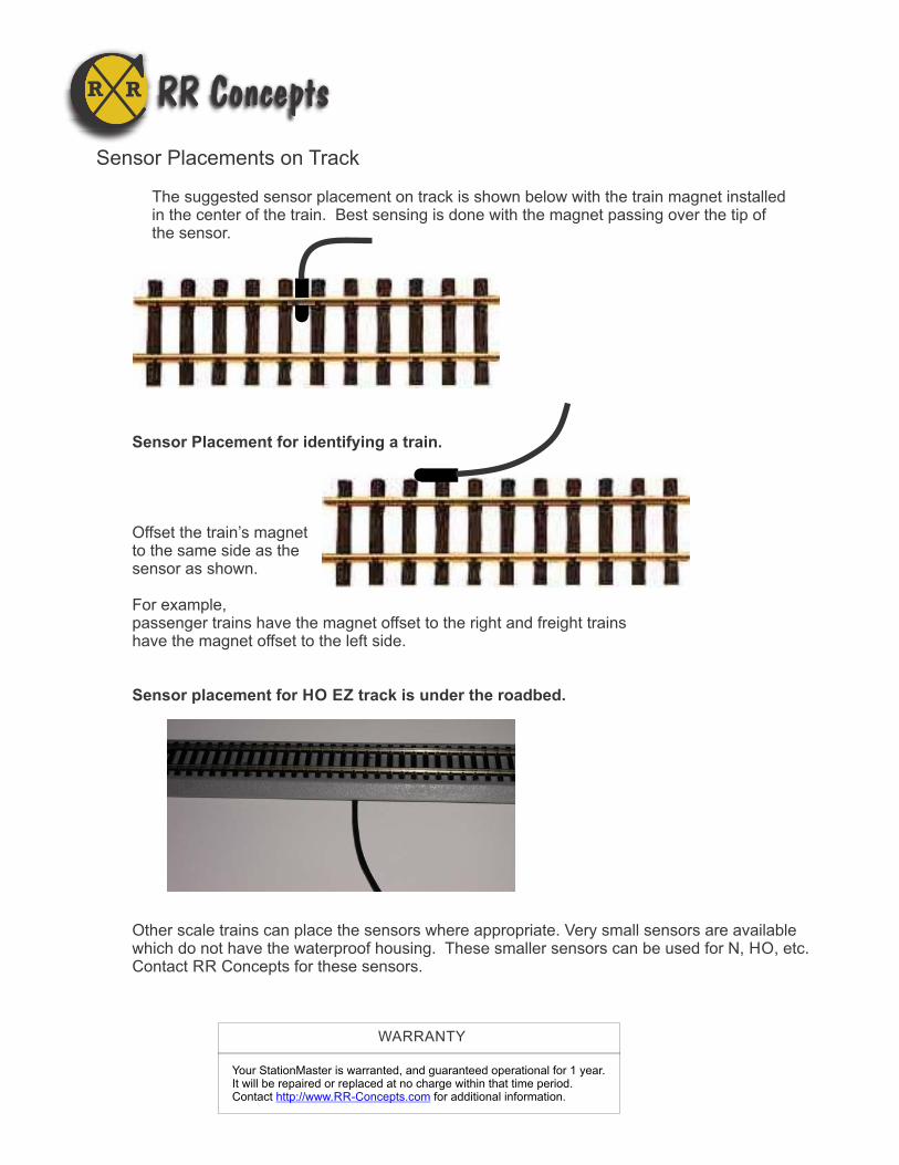
The suggested sensor placement on track is shown below with the train magnet installedin the center of the train. Best sensing is done with the magnet passing over the tip of the sensor.
Sensor Placement for identifying a train.
Offset the train’s magnetto the same side as thesensor as shown.
For example,passenger trains have the magnet offset to the right and freight trainshave the magnet offset to the left side.
Sensor placement for HO EZ track is under the roadbed.
Other scale trains can place the sensors where appropriate. Very small sensors are availablewhich do not have the waterproof housing. These smaller sensors can be used for N, HO, etc. Contact RR Concepts for these sensors.
Your StationMaster is warranted, and guaranteed operational for 1 year. It will be repaired or replaced at no charge within that time period. Contact for additional information.http://www.RR-Concepts.com
WARRANTY
CR R RR Concepts