rp-20 parking facilities
DESCRIPTION
RP 20TRANSCRIPT

RP-20-98
Lighting for Parking Facilities
Publication of this Committee Report has been approved by the IESNA. Suggestions for revisions should be directed to the IESNA.
Prepared by:
The Subcommittee on Off -Roadway Facilities of the IESNA Roadway Lighting Committee

Copyright 1998 by the Illuminating Engineering Society of North America.
Approved by the IESNA Board of Directors, December 5, 1998, as a Transaction of the Illuminating Engineering Society of North America.
All rights reserved. No part of this publication may be reproduced in any form, in any electronic retrieval system or otherwise, without prior written permission of the IESNA.
Published by the Illuminating Engineering Society of North America, 120 Wall Street, New York, New York 10005.
IESNA Standards and Guides are developed through committee consensus and produced by the IESNA Office in New York. Careful attention is given to style and accuracy. If any errors are noted in this document, please forward them to Rita Harrold, Director Educational and Technical Development, at the above address for verification and correction. The IESNA welcomes and urges feedback and comments.
Printed in the United States of America.
Cover photography courtesy of the Holophane Corporation, Newark, Ohio

Table of Contents
Foreword . . . . . . . . . . . . . . . . . . . . . . . . . . . . . . . . . . . . . . . . . . . . . . . . . . . . . . . . . . . . . . . . . . . . . . . . . ..i
1,Olntroduction . . . . . . . . . . . . . . . . . . . . . . . . . . . . . . . . . . . . . . . . . . . . . . . . ..~...................l
2.0PurposeandScope . . . . . . . . . . . . . . . . . . . . . . . . . . . . . . . . . . . . . . . . . . . . . . . . . . . . . . . . . . . . . . ..i
3.0 Types of Parking Facilities and Organization of the Practice 3.1 General ..................................... 3.2 Parking Lots ................................. 3.3Garages ..................................... 3.4 Organization of the Practice .....................
4.0 llluminance Recommendations -- Parking Lots ....... 4.1 General .................................. 4.2 High Vehicular Traffic Locations ............... 4.3 Security Lighting ........................... 4.4 Vertical llluminances ........................ 4.5 Shadowing and Sight Obstructions ............
5.0 Lighting Quality for Parking Lots 5.1 General ............... 5.2 Color Rendition ......... 5.3 Uniformity ............. 5.4 Glare ................. 5.5 Obtrusive Light .........
6.0 Light Sources for Parking Lots 6.1 Characteristics of Lamps
6.1.1 Types ............ 6.1.2 Life ............. 6.1.3 Efficacies ......... 6.1.4 Lumen Maintenance
6.2 Atmospheric Conditions 6.3 Lamp Configuration .... 6.4 Lamp Information ......
7.0 Lighting Equipment for Parking Lots 7.1 General .................. 7.2 Area Lighting Luminaires ....
7.2.1 Architectural .......... 7.2.2 Post Top ............. 7.2.3 Wall Mounted .......... 7.2.4 High Mast ............ 7.2.5 Roadway Lighting ......
7.3 Floodlighting Luminaires .....
........
........
........
........
........
........
........
........
........
8.0 Maintenance of Parking Lot Lighting ............... 8.1 General .................................. 8.2 Maintenance Factors .......................
8.2.1 Luminaire Dirt Depreciation (LDD) .......... 8.2.2 Lamp Lumen Depreciation (LLD) ........... 8.2.3 Equipment Operating Factor (EOF) .........
8.3 Maintenance and Operation Manual ...........
........
........
........
........
........
.........
.........
.........
.........
.........
. . . . I . .
. . . . . . . .
. . . . . . . .
. . . .
. . .
..........
..........
..........
.........
.........
.........
.........
.........
. . . . . . . . . .
........
........
........
. 2 . 2 . 2 2 2
. . 2 . 2
. . 4
. . 4 4 4
. . 5
. . 5
. . 5
. . 5 . 5 6
. . 6
. . 6
. 6 6
. . 6
. , 6
. . 6
. 7 . 7
. 7 . . 7
7 . 7 7
. . 8
. . 8 . 8 . 8
. . 9
. 9
. 9 . 9
. 9 . 9
. . 9

Table of Contents
9.0 Parking Lot Applications ........................................................... .9 9.1 Requirements ................................................................ . 9.2Vandalism ................................................................ ..10 9.3 Location of Standards and Light Sources ........................................ .I0
10.0 llluminance Recommendations -- Garages 10.1 General ....................... 10.2 Ramps and Entrances ............ 10.3 Uniformity ..................... 10.4 Stairways ...................... 10.5 Use of Daylight ................. 10.6 Emergency Lighting ............. 10.7 Special Lighting .................
............ ........ IO
............ ........ 10
............ ........ 10
............ ........ 11
............ ........ 11
............ ........ 12 ............ ........ 12 ............ ........ 12
11.0 Lighting Quality for Garages ...................................................... .12 ll.lGeneral ................................................................. ..12 11.2ColorRendition ........................................................... ..13 11.3Glare ................................................................... ..13
12.0LightSourcesforGarages ...................................................... ..13
13.0 Lighting Equipment for Garages .................................................... .13 13.1General ................................................................. ..13 13.2CutoffLuminaires ......................................................... ..I 3 13.3 Non-Cutoff Luminaires ...................................................... .13
14.0GarageApplications . . . . . . . . . . . . . . . . . . . . . . . . . . . . . . . . . . . . . . . . . . . . . . . . . . . . . . . . . . ...13
References . . . . . . . . . . . . . . . . . . . . . . . . . . . . . . . . . . . . . . . . . . . . . . . . . . . . . . . . . . . . . . . . . . . . . ...15
Annex A Tabular Comparisons of Common Lamp Types . . . . . . . . . . . . . . . . . . . . . . . . . . .I6
Annex B Illustrated Methods for Measuring llluminance and Making Photometric Evaluations in Parking Lots and Garages . . . . . . . . . . . . . . . . . . . . . . . . , . . . . . . . . . . . . . . . . . . . . .I8
Annex C General Procedure for Calculating Maintained llluminance in Parking Lots and Garages . . . . . . , . . . . . . . . . . . . . . . . . . . . . . . . . . , . . . . . . . . . . . . .23
Annex D Visibility-Based Analysis of Parking Facility Lighting . . . . . . . . . . . . . . . . . . . . . . . , . .33
Annex E SI(Metric)Conversions . . . . . . . . . . . . . . . . . . . . . . . . . . . . . . . . . . . . . . . . . . . . . . . . . ...40

IESNA RP-20-98
Lighting for Parking Facilities
Foreword
The following is a summary history on the evolution of this document (RP-20). It describes the progress leading to the current RP-20.
A Recommended Practice of Parking Area Lighting was prepared in 1960 by an IESNA Committee.’ This document specified as a basic value 11 Iux (--1 fc) average maintained horizontal illuminance, with a 4:l or better average/minimum uniformity ratio [minimum spot = 2.5 Iux (~0.25 fc)]. A doubling of these values was recommended at parking area entrances and exits.
In 1974, the IESNA Roadway Lighting Committee produced recommendations for lighting safety rest areas along limited access highways.2 A value of 11 Iux (1 fc) was specified for major activity sections, with a 3:l or better average to minimum uniformity. For lower activity zones (picnic areas, shelters), a 5 Iux (0.5 fc) illuminance and a 6:l uniformity were recommended. These values have been carried forward to the /ESNA Lighting Handbook, Eighth Edition3 and represent minimum values of 0.8 to 3.3 Iux (0.08 to 0.33 fc).
In 1984, a new IESNA Recommended Practice, Lighting for Parking facilities, (RP-20-84) was published.4 This document contained separate recommendations for lots and garages. Values were based on average illuminance for vehicle-use only areas of lots plus all areas of garages. For general parking and pedes- trian areas of lots, the recommendations were based on minimum illuminance values of 2 to IO Iux (0.2 to 1 fc). Maximum average-to-minimum uniformity ratios of 4: 1 were specified in most applications, pro- ducing average illuminance values of 8 to 40 lux (0.8 to 4 fc) when designed to this ratio. If designed as a highly uniform layout, such as with a 2:l uniformity, the average values would range from 4 to 20 lux (0.4 to 2 fc). Differences in assumed levels of activity for various land uses formed the basis of setting the range in recommended minimum illuminance values. This Practice also added vertical illuminance recommendations, specifying these to equal the horizontal values, measured at 1.5 meters (5.0 ft.) above the pavement.
RP-20-84 was not based upon surveys or field measurements of existing parking facilities - state- of-the-art prevailing practice relative to actual main- tained illuminance. Subsequent to its publication, reports surfaced of field measurements finding signifi- cantly lower levels in typical uses. A sampling survey of cities in 1991 found only one-fifth to be applying the RP-20-844 document in checking construction plans
for private parking facilities, which constitute the vast majority of lots and garages.
The IESNA Practice dealing with airport parking areas (RP-17-875) recommended 10 to 20 Iux (1 to 2 fc), average maintained illuminance, with a 4:1 uniformity ratio [2.5 to 5 Iux (0.25 to 0.5 fc) at low point].
In 1992! the Institute of Transportation Engineers (ITE) published its fourth Edition of the Traffic Engineering Handbook.6 Average illuminance values of 10 to 20 Iux (1 to 2 fc) were identified for parking lots, with uniformities not exceeding 6:l [minimum spot 1.7 to 3.3 Iux (0.17 to 0.33 fc)]. This was followed in 1994 with the ITE Recommended Practice Guidelines for Parking Facility Location and Design7 with the same recommendations. Both ITE publications followed the IESNA RP-20-844 recommendations for parking garages. These are 50 Iux (5 fc) average for general parking and pedestrian areas, with higher levels on ramps, in entrance areas, and on stairways.
The Recommended Building Code Provisions for Open Parking Structures,8 published by the National Parking Association in 1987, specified 65 Iux (6.5 fc) average at 75 cm (29.5 in.) above the floor, with a maximum uniformity ratio of 3:i. An earlier publication, Parking in the City Center, commissioned by the Automobile Manufacturers Association, recommended 33 to 54 Iux (3.3 to 5.4 fc) in garage parking areas.9
1 .O INTRODUCTION
Roadway Lighting Committee studies for the orderly passage of motorists and pedestrians have formed the basis of vehicular and pedestrian illuminance recommendations on public roadways. Combinations of interior, roadway, and pedestrian lighting techniques are applicable to parking lots (open) and parking garages (structures). Included in these facilities are:
l Vehicular traffic circulation, parking access aisles, parking stalls, and interior-access roadways and ramps in garages.
l Pedestrian traffic, including walkways and stairs.
20 PURPOSE AND SCOPE
Need exists to update and reach a consensus among the varying recommendations of different organizations. The primary purpose of this Practice is to serve as a guideline for design of fixed lighting for parking facilities. This Practice deals entirely with
1

IESNA RP-20-98
lighting and does not give advice on construction practice. This is a technical document which can be adopted as a guideline by local regulatory agencies. Its purpose is to provide recommended practices for designing new lighting systems for parking facilities and it is not intended to be applied to existing lighting systems until such systems are redesigned.
These recommendations include interior and exterior lighting practices for the reasonably safe movement of vehicular and pedestrian traffic in parking facilities, the enhancing of personal security and the deterring of vandalism, while conserving energy and minimizing maintenance. They provide minimum guidelines, but are subject to variations based upon sound engineering judgment. For example, retailers may prefer higher levels of illuminance than specified herein, to attract customers or to more strongly address perceptions of personal security needs. {See Sections 4.1 and 4.3.)
The guidelines exclude recommendations for public roads (see RP-8-83’O), bikeways and walkways (see DG-5-94”) and airport parking lots (see RP-17-875), which are given in other IESNA publications (as cited). Environmental issues (light trespass, light pollution, stray light, glare and control or light) are covered in detail in RP-33-99, /ESNA Recommended Practice on Lighting for Exterior Environments.
3.0 TYPES OF PARKING FACILITIES AND ORGANIZATION OF THE PRACTICE
3.1 General
This Practice applies to active parking facilities serving the public or employees. These facilities are classified as parking lots or garages. A description of both types follows.
3.2 Parking Lots
Parking lots are facilities that are not roofed or enclosed. Parking stalls in a lot that are covered by shed roofs but not otherwise enclosed, and with access aisles open to the sky are considered as parking lots. This Practice does not deal with curb parking along streets (see RP-20-844 or the /ESNA Lighting Handbooks) nor with public airport parking lots (see RP-1 7-875). ,
3.3 Garages
Garages consist of one or more vertically stacked parking levels, roofed over, and enclosed, plus ramps providing access, In an above-ground facility, some
2
or all of the enclosure walls customarily are partially open to provide ventilation. In an underground garage, enclosure usually is complete, however lightwells are sometimes provided. In any garage, the illuminance needs of the top parking level - if open to the sky - are similar to those of an open lot with enhanced security. This Practice does not deal with garages for vehicle repair or new car storage.
3.4 Organization of the Practice
The illuminance requirements of a parking facility are affected by the layout, operation and vehicular traffic safety issues, plus the visibility and security needs of pedestrians walking to or from their vehicles. There are significant differences between lots and garages. Garages usually require supplemental daytime illumi- nance in above-ground facilities, and full day and night lighting for underground facilities. Types of lighting equipment, security aspects and illuminance needs are significantly different between lots and garages. Therefore, this Practice is divided into two parts; recommendations for parking lots (Section 4.0 through Section 9.0) and recommendations for garages (Section 10.0 through Section 14.0).
4.0 ILLUMINANCE RECOMMENDATl6NS - PARKING LOTS
4.1 General
Parking lots and parking structures have vehicular speeds that are much lower than roadways. More importantly, the primary purpose of the lighting here is to benefit the pedestrian. It is intended that a driver (or pedestrian) looking at the brightest spot in the field of view will also be able to detect an object in the dark areas within the field of view. This detection can only occur if the maximum-to-minimum illuminance is limited to a range that the human eye can see. Even when it can be accurately determined, average illuminance has no practical bearing on the range of illuminance compatible with seeing. Therefore, citing maximum-to-minimum illuminance for parking lots or parking structures is a better specification method than using average-to minimum illuminance recom- mended in RP-20-84.
The maximum-to-minimum method is also based on easily obtained measurements as compared with the time-consuming and often impractical (due to parked vehicles) measurement of individual point-to- point values required to calculate the “average” value prescribed in LM-64-91, Photometric Measure- ments of Parking Areas and in the previous edition of this practice @P-20-84).

llluminance recommendations for active parking lots open to customers, employees, or the general public are given in Table 1. The illuminance is to be measured or calculated on a clear pavement, without any parked vehicles. The maximum and minimum values are maintained illuminances. This condition occurs just prior to lamp replacement and luminaire cleaning. If the lamp catalog does not give end-of-life data, these should be secured from the manufacturer.
Note: While illuminance criteria are the basis for lighting recommendations in this Practice, there is a trend to using luminance criteria for many applications. Luminance is what an individual “sees” or perceives. Luminance ratios between surfaces better describe how the eye views and adapts to the visual environ- ment, and luminance contrast is important in detec- ting objects against their background in visibility- based calculations. (See Annex D.)
Data from various studies of vehicular accidents in parking lots have shown about two-thirds involved a moving vehicle striking a parked vehicle, less than one-third involved a moving vehicle striking another
IESNA RI=‘-20-98
moving vehicle, about six percent involved striking fixed objects, and one percent involved striking pedestrians.‘* An average of 20 percent of these accidents occurred at night. Furthermore, the highest proportion (38 percent) of these night accidents involved avoiding pedestrians. However, this study did not include pedestrian slips or trips and falls, which were not recorded by police accident reports. If these were included in the consideration of parking facility lighting needs, then the proportion of total mishaps involving pedestrians would be greater than one percent. A major study of claims in commercial parking facilities found slip or trip-and-fall pedestrian accidents accounted for about 75 percent of the number of total claims and slightly over 50 percent of the costs paid.13 The study found seven percent of the claims represented personal assault, nine percent vehicle damage, and five percent gate damage.
A paper by Monahan14 examined the required contrast to see a 15-cm (6-in.) curb against a concrete floor of assumed reflectance, at a distance of 6 meters (20 ft.). The increased contrast required as a function of illuminance for a 60-year-old observer was plotted
Table 1: Recommended Maintained llluminance Values for Parking Lots
Basic’ Enhanced Security*
Minimum Horizontal Illuminance3 Iux4 2 5 fc’ 0.2 0.5 _
Uniformity Ratio, Maximum to Minimum6 2O:l 15:l
Minimum Vertical Illuminance7 Iux8 1 2.5 fC5 0.1 0.25
1 For typical conditions. During periods of non-use, the illuminance of certain parking facilities may be turned off of reduced to conserve energy. If reduced lighting is to be used only for the purpose of property security, it is desirable that the minimum (low point) value not be less than 1 .O horizontal lux (0.1 hfc). Reductions should not be applied to facilities subject to intermittent night use, such as at apartments, hospitals, and transportation terminals.
* If personal security or vandalism is a likely and/or severe problem, a significant increase of the Basic level may be appropriate (see Section 4.3). Many retailers prefer even higher levels, with a specification of 10 Iux (1 fc) as the minimum value.
3 For preliminary design, an average value of 10 horizontal Iux (1 hfc) for basic, or 25 horizontal Iux (2.5 hfc) for enhanced illuminance may be calculated. The minimum points (or areas) and maximum point are then calculated and the uniformity ratio checked for compliance with the Table 1 values (see Section 5.3). Note: The 51 average-to-minimum ratio is the first step toward directing the design to achieve the maximum to minimum ratios presented in Table 1.
4 Measured on the parking surface, without any shadowing effect from parked vehicles or trees at points of measurement.
5 Rounded conversion of Iux to footcandles (see Annex E).
s The highest horizontal illuminance point divided by the lowest horizontal illuminance point or area should not be greater than the values shown (see Section 4.4 and Annex B).
7 Facial recognition can be made at levels a low as 2.5 Iux (0.25 fc). The IESNA Security Lighting Committee recommends that for facial identification, the minimum vertical illuminance should be 5.0 Iux (0.5 fc).
s Measured at 1.5 meters (5.0 ft.) above parking surface at the point of lowest horizontal illuminance. excluding facing outward alOng
boundaries (see Section 4.4 and Annex B).
Note 7: The height of the measurement has been lowered from the previous 1.8 meters (6 ft.) of RP-20-84 to be in line with the average human observers eye height of 1.5 meters (5 ft.)
Note 2: A survey of existing installations by the authoring committee found that a value of 1 Iux (0.1 fc) minimum vertical illuminance was achievable using cutoff luminaires, but values greater than this may not be achievable.
3

IESNA RP-20-98
(see Annex D, Figure 02). In this example, when the Visibility-based Analysis Procedure (Annex D) is used, a minimum point value of 10 lux (1 fc) must be provided throughout the parking lot (horizontal illu- minance on the parking lot surface) or garage to insure the visibility required to see wheel stops, curbs, pole bases, and incidental objects such as broken exhaust system parts which commonly appear on parking lot property.
Basic lighting requirements tend to be similar for most land uses. Typical or average security needs are equally as great in a parking lot serving an apartment building or a regional shopping center. In fact, the higher the pedestrian activity level, the lower the likely security problem. However, greater pedestrian activity usually equates to greater conflict with vehicles. Because these conditions tend to counter- balance, no difference in the basic level of illumi- nance appears warranted among various land uses. However, customer attraction can be a reason to provide illuminance higher than the basic illumi- nance level given in Table 1. When higher light levels are used, retailers should give careful consider- ation to the safety consequences of drivers exiting the parking facility directly onto adjacent streets with lower lighting levels. Needs for enhanced personal’security are addressed in the table and are further discussed in Section 4.3.
4.2 High Vehicular Traffic Locations
Exits, entrances, gate access, internal connecting roadways, or ring roads and cross-aisles should be given special consideration to permit ready identification and to enhance safety. Generally, higher illuminance should be provided along these routes by using lumi- naires in appropriate locations.
llluminance of the driveway access to streets should at least match any local public lighting. For high volume driveways, such as at community- or regional-size shopping centers, increasing the average public road lighting level 50 percent is desirable. However, this should be compatible with local conditions. If the street has no lighting, the Table 1 “basic value” can be used, applicable to the near curb line.
4.3 Security Lighting
In areas where personal security is a likely problem, the recommended increase of the basic parking lot minimum illuminance given in Table 1 is intended to reduce user apprehension and facilitate the observation of potential assailants. Limited studies have identified lighting as a factor in crime reduction: however they have not been quantified - nor is this likely.
While personal assaults and vandalism do occur in broad daylight because light is only one of many fac- tors influencing security, night time offenses are more likely to occur in areas with little or no lighting. While several major retailers specify a minimum value of 10 Iux (1 fc) in their parking lots, measurements within existing facilities often find much less light. Iden- tification of faces is a key factor in the crime deterrent effect of lighting, yet vertical illuminance is rarely specified. In any case, the degree of enhanced light- ing to serve perceived security needs is a local judg- ment factor. At certain locations where night activity levels are high - such as at automatic teller machines - the immediate surrounding area may require illuminance levels substantially greater than those recommended herein. This issue is addressed by IESNA DG-9-9715, Lighting for Automatic Teller Machines. The Color Rendering Index (CRI) also warrants consideration, with values of 60 or greater recommended for enhanced security. See Section 5.2, Section 11.2, and Table Al in Annex A.
4.4 Vertical llluminances
Boyce and Rea found one lux of vertical illumi- nance is sufficient to obtain a 90 percent proba- bility of correct detection of an approaching person (but not facial recognition).16 For visibility of objects such as curbs, poles, and fire hydrants in parking areas, and to aid in detecting other pedestrians, the vertical Iux value at the lowest unshadowed point between luminaires in the area of minimum horizontal illuminance (see Section 5.3) is recommended to be at least one-half the minimum horizontal value given in Table 1, and preferably greater. These values obviously do not apply to a direction facing ouhvardalong a boundary, because this would require lighting units beyond the property line. Similarly, the outer side does not apply beyond an outer line of luminaires located inside the boundary line (see Annex B). The values are for a location 1.5 meters (5.0 ft.) above the pavement. They may include the vertical illumi- nance from luminaires at right angles to the point of measurement, because an observer can be located in a broad area between adjacent luminaires (see Figure C3 and Section C9.0 in Annex C).
4.5 Shadowing and Sight Obstructions
Landscaping of a parking lot often includes trees. These are typically located in boundary strips, parking row end islands, or in curbed strips between parking modules. The light pole locations and mounting height selections should be coordi- nated with the landscaping plan and/or existing trees. The mature branch spread of trees should be considered so as to minimize future shadowing.
4

I ESNA RP-20-98
The shadow effects of fixed objects such as large signs or building walls also should be examined. It is sometimes practical to adjust luminaire locations to minimize or even eliminate such conditions. Other effects traceable to changes in landscape topo- graphy should also be considered, such as mound- ed islands and seat walls. Seasonal conditions such as large snow accumulations, plowing patterns for snow removal, and the piling of removed snow may create recurrent obstructions that produce shadows when low-mounted metal halide units are used, a condition which should be accommodated by the lighting design.
5.0 LIGHTING QUALITY FOR PARKING LOTS
5.1 General
While lighting for parking lots should deliver the recommended minimum illuminance levels, it should also provide reasonable quality. The designer will need to consider color rendition, uniformity, and minimized glare.
5.2 Color Rendition
In many parking installations lamp spectral output must be capable of rendering colors so that persons, whether walking or driving in the area, will be able to distinguish colors and differentiate objects within their field of vision. Individuals sometimes have trouble identifying their cars under sources with poor color rendering characteristics. Various lamp types are available that can produce a variety of color envi- ronments (see Table Al in Annex A). This factor should be considered during the lighting system’s design. Recent research by A. L. Lewis,17s18 W. AdrianI and M. C. Belcherm show that in low level luminance the spectral output of various lamps plays an important part in the eye’s ability to detect objects and hazards within its field-of-view.
5.3 Uniformity
The illuminance at points within parking areas can vary greatly. Calculations for uniformity, employing the horizontal illuminance method, should be made for a maximum-to-minimum ratio not exceeding those recommended in Table I. As a first approximation in design, an average overall illuminance value may be chosen - 10 lux (1 fc) for a “basic” design or 25 Iux (2.5 fc) for an “enhanced” design. The maximum and minimum points are then calculated. If these points fall within the uniformity ratios of Table I, the design obviously meets these criteria. Further analysis of uniformity, based on areas (see the following para-
graph), would be needed for consideration of alter- nate designs such as using higher wattage lamps at greater spacing, or changing the mounting height to reduce energy consumption or trim capital costs.
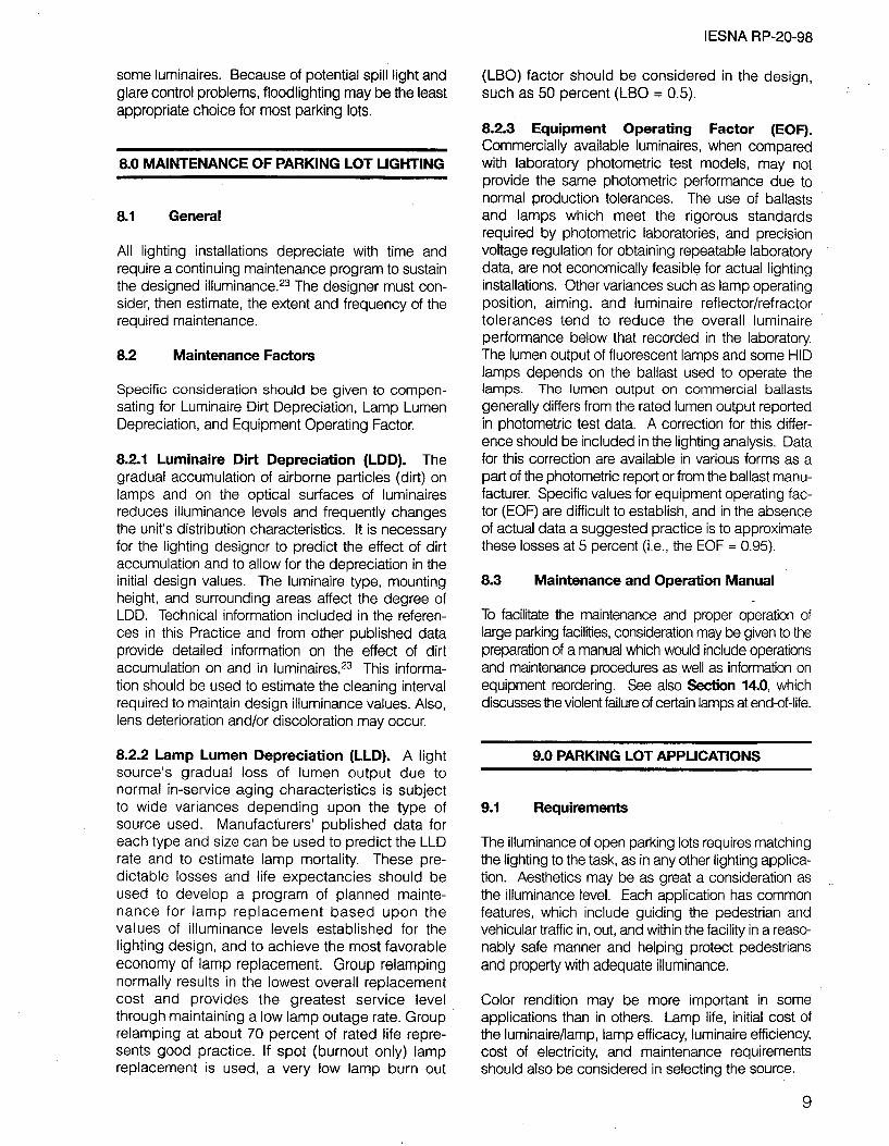
As an alternative method, ,the “minimum” may be considered as a small area between luminaires rather than the specific point with the actual lowest value, because this spot could be shadowed by a pole or tree limb. This simplified method will better approximate the Statistical Uniformity Concept proposed by Mathieu or the Coefficient of Variation developed by Armstrong than using only a single spot.21,2z In general, the minimum area values can be considered the average of those five points at (and immediately surrounding) the point where the calculated or measured minimum values would fall. The test grid should be a square with sides measuring one-tenth of the greatest spacing between luminaires but not more than five meters (16 feet) on a side (see Annex B for an example). The greatest spacing between luminaires is determined as follows:
Step 1: For a given pole, determine the distance to that pole which is nearest to the given pole.
Step 2: Repeat Step 1 for each pole in the layout. Step 3: The greatest spacing is the largest number
obtained in Step 2.
Where one or more luminaires is not pole-borne, the distance is determined by using a point -at grade directly beneath the luminaire.
Upon completion of the installation, the results obtained may be compared to the design criteria by measuring levels and calculating the uniformities.
5.4 Glare
Glare is the sensation produced by luminance within the visual field that is sufficiently greater than the luminance to which the eyes are adapted, so as to cause annoyance, discomfort, or loss in visual performance or visibility. There are two types of glare:
Disability G/are: reduces the ability to see or identify objects.
Discomfort G/are: produces ocular discomfort, but does not reduce the ability to see.
Reasonable shielding of lamps, reflectors, or lenses will enhance visibility and should be considered during the design process (see Figure 1). Glare presents more of a problem for older persons, affecting their ability to clearly perceive objects or obstructions.
5

I ESNA RP-20-98
For a more definitive analysis of glare, calculate the maximum veiling luminance of the system (Lvr& and compare it with the average pavement luminance (L&. The ratio (Lvmax )/(L& should be less than 0.3 to 1.10
5.5 Obtrusive Light
In open parking areas, upward light represents wasted energy, contributes to undesirable sky glow, and should be minimized. Downward spill light beyond the boundary may be undesirable depending upon where it falls. If the adjacent land use is resi- dential, any significant spill light is unwelcome and probably prohibited by local ordinances. For an in- depth treatment of the subject, see HP-33-99, /ESNA Recommended Practice on Lighting for Exterior Environments.
Ordinances may also limit the spill-over light allowed onto adjacent streets. This should not represent a problem to the community, because additional lighting along the street will typically enhance safety. The designer may wish to discuss this issue with the local officials, because the key concern should be glare. In selecting the orientation, location, and mounting heights of luminaires, the designer should strive to control glare beyond the parking boundaries, as well as within.
6.0 Light Sources for Parking Lots
6.1 Characteristics of Lamps
6.1.1 Types. Lamps typically used in parking lots include mercury vapor, high pressure sodium, metal halide, and some low pressure sodium. The advan- tages and disadvantages of various lamp types are
summarized in Table A2 in Annex A. (Note: Using mercury HID lamps is considered poor lighting prac- tice because today other more efficient sources are available. However, in some rural locals, mercury vapor lighting is the only readily available equipment. Clear mercury vapor and low pressure sodium have severe spectral distribution limitations. Low pressure sodium, which is a monochromatic source, is used by several cities near important astronomical observa- tories because the monochromatic spectrum can be easily filtered out during deep sky astronomical obser- vations.)
6.1.2 Life. Life ratings of lamps are furnished by manufacturers. This information should be considered in the design (see Section 8.2.2).
6.1.3 Efficqcies. The term “lamp efficacy,” as used herein, applies to the ratio of total lamp output in lumens to the power input expressed in watts to operate the lamp; i.e., lumens per watt (LPW), including ballast losses, where applicable. It is an energy management issue.
6.1.4 Lumen Maintenance. Lumen depreciation relates to the light output throughout the life of the lamp as a direct result of electrode deterioration and lamp blackening. Each design should provide the required minimum lighting levels at time of relamping. Therefore, design should be based on the relamping program to be used (see Section 8.2.2).
6.2 Atmospheric Conditions
When luminaires are selected which will expose the lamp to the effects of temperature and cold seasonal
MAXIMUM CANDELA IN kcd
Figure 1. Minimum luminaire mounting heights based on current practice and veiling luminance calculations.
6

IESNA RP-20-98
climatic changes, consideration must be given to the possible use of starting aids for gas-discharge lamps. Incandescent filament lamps will operate at any reasonable ambient temperature, but tempera- tures can affect the starting ability and the light output of other types, particularly some types of fluorescent lamps. Ballasts are available to reduce the effects of ambient temperature down to approximately -30°C (-22°F) and, in some cases, even lower temperatures. (They do not maintain the normal light output obtained when operated at higher ambient tempera- tures, but they do provide lamp starting ability.) Jacketed lamps are also used at extremely low ambient temperatures or where the lamp is exposed to “airflow” conditions.
6.3 Lamp Configuration
The dimensions of the lamp’s luminous element are important because they directly impact the effec- tiveness of light control. The larger the luminous element, the larger the reflector and/refractor system must be in order to control the light output, and the more difficult the control becomes. However, glare is somewhat mitigated by lower surface brightness. The lamp, ballast, and luminaire combination repre- sents a lighting unit designed for a specific perfor- mance. Labels indicating proper lamp wattage are affixed to the luminaire and required by electrical testing laboratories. It is essential that the proper lamp be used if specified lighting criteria are to be met.
6.4 Lamp Information
Each lamp manufacturer publishes the physical size and shape of its lamps and supplies information on lamp life, efficacy, and lumen depreciation. Shape is indicated by a letter or letters, and size by a number indicating the diameter of the lamp. Information is also given for the type of base used. Additional infor- mation, such as candela distribution of the lamp and/or lamp/luminaire, restrike time (which may be up to 30 minutes for certain types of lamps), and normal operating position is usually available upon request. If color rendering is an important factor in the selection of the lamp, the designer should refer to Section 11.2, to Table Al in Annex A, and to the IESNA Lighting Handbook.3
7.0 LIGHTING EQUIPMENT FOR PARKING LOTS
7.1 General
Parking lots use a variety of lamps and luminaires (e.g., area lighting, architectural, post top, wall moun- ted, high mast, roadway lighting, and floodlighting
luminaires). Of these types, the area, roadway lighting, and floodlighting luminaires are most commonly used in outdoor applications.
The luminaire types best suited for a specific application can be determined by comparing lamp and luminaire combinations to basic considerations, such as:
l Size and shape of area l Mounting height of luminaire l Location requirements of poles and luminaires l llluminance requirements and control of glare l Uniformity requirements (maximum-to-minimum) l Energy requirements (lamp source and ballast) l Code restrictions l Effects of spill light on any adjacent residential
property and on sky glow
7.2 Area Lighting Luminaires
Area lighting luminaires are designed to illuminate specific geometric areas. Typically, they use fixed mounting, and the lighting is controlled by a combi- nation of refractor and reflector elements (or a multi- ple reflecting system) by location and by orientation within the area to be lighted. They may be further defined as:
l Architectural l Post top l Wall mounted 0 High mast l Roadway lighting
7.2.1 Architectural. A wide variety of architectural luminaires is available. These are designed to blend with the total architectural environment and may be capable of producing efficient, uniform illuminance, while offering control of undesirable light or glare. Typically, they are classified in accordance with the American National Standard Practice for Roadway Lighting.‘O
Because it is often desirable to obscure the light source in normal applications, architectural lumi- naires may provide light distribution through reflector systems. Efficiencies of this luminaire type may be comparable to other types; however, with the reduction of disability veiling brightness and discomfort glare, the overall visibility may be improved.
7.2.2 Post Top. Though they have many similarities with architectural luminaires in design philosophy, post top luminaires are distinct due to their location in the parking facility. Generally, they offer a symmetrical distribution of light, but asymmetrical distributions also are available. There are two categories of post
7

IESNA RP-20-98
top luminaires available; direct and indirect. These luminaires are usually located within the parking area (away from the perimeter). Mounting heights for direct type luminaires are usually limited to 8 meters (26 ft.) or less. Indirect type luminaires can usually be supplied as an alternate mounting method to (and match the appearance of) arm mounted luminaires. The optical control method used is specific to each post top luminaire type:
_. Direct - Optical control for direct post top lumi- naires can be obtained using reflectors as well as refractors. A high luminance source may provide suitable illuminance and a sense of security However, care should be taken to avoid excessive glare.
Indirect - Indirect post top luminaires shield the light source from normal view. Optical control is gained by totally reflecting the light downward to the area being lighted. This can provide excellent glare control along with important aesthetic values. However, this type is typically less efficient (requires higher lamp output) than the types producing direct light and is usually limited to symmetric distributions.
7.2.3 Wall Mounted. Relatively narrow parking areas that are between or adjacent to buildings can be conveniently lighted by wall mounted luminaires. These luminaires are available in many architectural styles. Mounting height is usually 8 meters (26. ft.) or less. A wide variety of lighting distributions are available for this type but, in general, they fall into two categories; cutoff and semi-cutoff:
Cutoff-Wall mounted cutoff luminaires are typically projection-type offering good lighting for up to several times the mounting height in front of the luminaire with lateral spacings typically limited to two times the mounting height.
Semi-Cutoff-Wall mounted semi-cutoff luminaires, utilizing a refracting element in conjunction with the reflector, can allow a lateral spacing of one and a half to two times their mounting height, and a longitudinal spacing of six to eight times their mounting height, provided this equipment allows the designer to meet the recommendations for both uniformity and illumi- nance. Also, excessive glare and the potential for significant light spill must be avoided or controlled.
7.2.4 High Mast. Used at mounting heights of 20 meters (66 ft.) and up, the high mast luminaire provides illuminance for’ large areas with a limited number of poles. Highly efficient lighting with excellent comfort levels can be provided for very large areas by using high mast installations. Consideration must be given to system maintenance
and luminaire accessibility when selecting this type of equipment. Further, it is generally suitable only for nonresidential areas. While other types of area lighting equipment are readily available in many wattage and source combinations, high mast equipment typically uses the higher wattage sources.
Luminaires are available in both symmetrical and asymmetrical distributions utilizing refractor and/or reflector or indirect control of light output. Shielding by metal reflector sheet or optics can provide cutoff of lighting as required. Paint also is used, but gradual deterioration can allow increased glare and variability of photometric performance. With the variety of equipment available, greater flexibility in pole locations is possible in designs so that poles can be placed along perimeters of areas to be lighted with a minimum of interference or spill light encroaching on adjacent properties. A high mounting height for luminaires may assist in minimizing shadows between parked vehicles, but can be offensive to adjacent property owners.
7.2.5 Roadway Lighting. Available with various types of light sources and wattage ratings, roadway lighting luminaires exhibit a range of symmetric and asymmetric distributions. See the American National Standard Practice for Roadway Lighting.lO These units generally have both reflector and refractor control; however, units are available that use only reflector control. Mounting heights are typically 8 meters (26 ft) and higher.
7.3 Floodlighting Luminaires
Floodlighting luminaires are designed with a projected beam for lighting a scene or object to a luminance considerably greater than its surroundings and are usually capable of being aimed in any direction. Their use is dictated primarily by luminaire location and the task size being lighted. For example, if the location is remote from the parking area, floodlighting is required to project light to the task. Also, irregular areas may require the more precise control offered by floodlight equipment.
Floodlighting systems are available in symmetric and asymmetric distributions. Where the area to be lighted requires a wide distribution of light: but further demands control of that light across the area, such as in perimeter lighting, an asymmetric distribution may be employed. For clarification of the types of floodlighting distribution available, refer to the /ESNA Lighting Handbook.3 Accessories, such as louvers and visors, are readily available to limit high angle light and thus reduce glare and discomfort; however, they may decrease the light output and useful life of
8
IESNA RP-20-98
some luminaires. Because of potential spill light and glare control problems, floodlighting may be the least appropriate choice for most parking lots.
8.0 MAINTENANCE OF PARKING LOT LIGHTING
8.1 General
All lighting installations depreciate with time and require a continuing maintenance program to sustain the designed illuminance. 23 The designer must con- sider, then estimate, the extent and frequency of the required maintenance.
8.2 Maintenance Factors
Specific consideration should be given to compen- sating for Luminaire Dirt Depreciation, Lamp Lumen Depreciation, and Equipment Operating Factor.
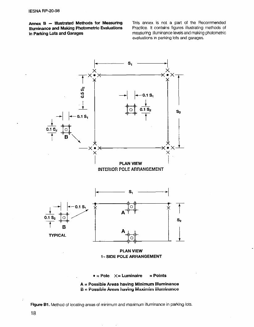
8.2.1 Luminaire Dirt Depreciation (LDD). The gradual accumulation of airborne particles (dirt) on lamps and on the optical surfaces of luminaires reduces illuminance levels and frequently changes the unit’s distribution characteristics. It is necessary for the lighting designer to predict the effect of dirt accumulation and to allow for the depreciation in the initial design values. The luminaire type, mounting height, and surrounding areas affect the degree of LDD. Technical information included in the referen- ces in this Practice and from other published data provide detailed information on the effect of dirt accumulation on and in luminaires.23 This informa- tion should be used to estimate the cleaning interval required to maintain design illuminance values. Also, lens deterioration and/or discoloration may occur.
8.2.2 Lamp Lumen Depreciation (LLD). A light source’s gradual loss of lumen output due to normal in-service aging characteristics is subject to wide variances depending upon the type of source used. Manufacturers’ published data for each type and size can be used to predict the LLD rate and to estimate lamp mortality. These pre- dictable losses and life expectancies should be used to develop a program of planned mainte- nance for lamp replacement based upon the values of illuminance levels established for the lighting design, and to achieve the most favorable economy of lamp replacement. Group relamping normally results in the lowest overall replacement cost and provides the greatest service level through maintaining a low lamp outage rate. Group relamping at about 70 percent of rated life repre- sents good practice. If spot (burnout only) lamp replacement is used, a very low lamp burn out
(LBO) factor should be considered in the design, such as 50 percent (LB0 = 0.5).
8.2.3 Equipment Operating Factor (EOF). Commercially available luminaires, when compared with laboratory photometric test models, may not provide the same photometric performance due to normal production tolerances. The use of ballasts and lamps which meet the rigorous standards required by photometric laboratories, and precision voltage regulation for obtaining repeatable laboratory data, are not economically feasible for actual lighting installations. Other variances such as lamp operating position, aiming, and luminaire reflector/refractor tolerances tend to reduce the overall luminaire performance below that recorded in the laboratory. The lumen output of fluorescent lamps and some HID lamps depends on the ballast used to operate the lamps. The lumen output on commercial ballasts generally differs from the rated lumen output reported in photometric test data. A correction for this differ- ence should be included in the lighting analysis. Data for this correction are available in various forms as a part of the photometric report or from the ballast manu- facturer. Specific values for equipment operating fac- tor (EOF) are difficult to establish, and in the absence of actual data a suggested practice is to approximate these losses at 5 percent (i.e., the EOF = 0.95).
8.3 Maintenance and Operation Manual
To facilitate the maintenance and proper operation of large parking facilities, consideration may be given to the preparation of a manual which would include operations and maintenance procedures as well as information on equipment reordering. See also Section 14.0, which discusses the violent failure of certain lamps at endof-life.
9.0 PARKING LOT APPLICATIONS
9.1 Requirements
The illuminance of open parking lots requires matching the lighting to the task, as in any other lighting applica- tion. Aesthetics may be as great a consideration as the illuminance level. Each application has common features, which include guiding the pedestrian and vehicular traffic in, out, and within the facility in a reaso- nably safe manner and helping protect pedestrians and properly with adequate illuminance.
Color rendition may be more important in some applications than in others. Lamp life, initial cost of the luminaire/lamp, lamp efficacy, luminaire efficiency, cost of electricity, and maintenance requirements should also be considered in selecting the source.
9

IESNA RP-20-98
Facilities for roadside safety rest areas generally require higher illuminances than the basic.24 Levels should be based on deterring vandalism and theft as well as pedestrian security.
llluminance of outdoor pedestrian walkways separate from parking areas should be in accordance with RP-8-83 American National Standard Practice for Roadway Lighting,‘0 or DG-5-94 Recommended Lighting for Walkways and Class 7 f3ikeways1’ Particular atten- tion should be given to the placement and shielding of luminaires, which should be located to prevent glare at eye level (see Annex C, reference Figure 24-l 1 from the /fSNA Lighting Handbook3). In outdoor stairways, it may be necessary to place a unit on every landing, with additional units between if requi- red for safety Special treatment may be necessary to mark changes in elevation wherever one or more steps are required.
9.2 Vandalism
Vandalism can generally be reduced by mounting luminaires at least 3 meters (9.8 ft.) above ground level. Greater mounting heights are recommen- ded. Materials such as tempered glass, high impact acrylic, and polycarbonate are extremely useful in damage reduction when incorporated into shields, lenses, refractors, or globes. Metallic or high impact plastic guards can help protect lumi- naire optical assemblies from damage, although such guards may cast shadows and thus reduce the luminaire’s efficiency.
9.3 Location of Standards and Light Sources
Support poles should be strategically placed to reduce the probability of damage to (or from) moving automobiles. Designers should be aware that certain automobiles overhang approximately 0.5 to 1.0 meters (1.6 to 3.3 ft.) in front and up to 1.52 meters (5.0 ft.) in the rear. For protection, poles are some- times mounted on raised concrete bases. However, these bases represent a fixed object hazard. This can be addressed by painting reflectorized bands on the bases.
The locations and mounting heights of all luminai- res and accessories must allow access with readily available maintenance equipment. Long brackets should be avoided if luminaires are serviced from ladders or if the mounting poles are to be climbed. Hinged poles may also be considered. It must be possible to energize circuits during the daytime for testing and trouble shooting.
10
10.0 ILLUMINANCE RECOMMENDATIONS- GARAGES
10.1 General
Lighting for parking structures and parking bays may be characterized as illuminating long, narrow “rooms” having low mounting heights (for luminaires) and low (20-40 percent) surface reflectances.
Parking structures often have a high incidence of pedestrian/vehicle conflict. Here, drivers and pedes- trians must contend with structural columns, pipe bollards, guard rails, railings, and changes in surface elevation (involving steps or curbing), and pavement markings, which create a variety of complicated visual tasks requiring adequate visibility.
A high degree of maximum-to-minimum illumination uniformity should be maintained within the parking structure, since the driving lanes are often used by people walking to/from their parked vehicles and the exits, elevators, or stairwells. These pedes- trians must often travel across the driving lanes to reach these exits, putting them in direct conflict with vehicular traffic. Thus it is important to avoid creating dark areas with improperly-spaced or poorly-maintained luminaires. Dim light or shadows could cause some pedestrians to go undetected by drivers.
The illuminance recommendations for parking structures (garages) are given in Table 2. These apply to covered and enclosed self-parking facili- ties intended for use by residents, customers, and employees of apartment buildings or commercial developments and by the general public. The limited mounting height available in a parking structure, the normal density of vehicle parking, the need for signage, the obstructions that drivers and pedestrians must negotiate, the presence of shadows between vehicles and structures, and the difficulty in maintaining ade- quate surface reflectance on ceilings, walls, and barricades increases the need for higher initial and maintained illuminance. Table 2 does not apply to garages used exclusively for repair, vehicle storage, or where all vehicles are parked by attendants. Recommendations for illuminating these facilities appear in the IESNA Lighting Handbook.3
10.2 Ramps and Entrances
There are two general types of ramps - those contained entirely within the garage structure, and those mounted along the sides or at an end. The latter are usually open to the sky and may require little or

no daytime lighting. Ramps with parking along one or ments, from the 500 Iux (50 fc) entrance area to the both sides are called sloping floor designs and require 20 Iux (2 fc) ramp area or the 10 Iux (1 fc) basic area, only basic garage ilfuminance. over each lo-meter (33 ft.) run length.
In garages, the entrance area is defined as the drive aisle and any immediately adjacent parking stalls, from the portal or physical building line to about 20 meters (66 ft.) inside the structure. Where parking is not provided next to the drive lane, the width of entrance area should be defined by adjacent walls, if any. However, the width should not exceed 15 meters (50 ft.). Higher illuminance is needed during the day for this transition area which connects full daylight to the relatively low interior illuminance levels. A garage entrance is somewhat analogous to a tunnel portal, except that vehicle speeds are much lower- typically only 10 to 20 km/hr (6 to 12 miles/hr). Ordinarily, garage entry involves turning off a street or service road. Entrances designed with a straight run of 50 meters (164 ft.) or more can accept vehicles at higher speeds and may require corre- spondingly longer transition areas. Beyond the first 20 meters (66 ft.), the illuminance can be stepped down in successive stages, such as one-third incre-
10.3 Uniformity
As with parking lots, the average of the lowest area of garage floor illuminance may be used as an alternative calculation of the minimum rather than the absolute lowest point. This area is a rectangle (see Annex B). A point, centered below one of the luminaires, should be used to calculate or measure the most likely maxi- mum illuminance value. To start the design, an aver- age overall illuminance value may be chosen - 50 Iux (5 fc) for parking floors and proportionately higher values for elements requiring greater illuminance. The maxjq@m and minimum points are then calculated. If the minimum is met and the ratio of the maximum and minimum points falls within the 1O:l uniformity ratio given in Table 2, the design meets the criterion. Further analysis of uniformity based on minimum areas would be needed if alternate designs are considered (e.g., the use of larger lamps at greater spacing to cut energy consumption and/or reduce capital cost).
IESNA RP-20-98
Table 2: Recommended Maintained llluminance Values for Parking Garages
. I Maximum/Minimum Miminum Horizontal* ’
Horizontal Minimum Uniformity Vertical5
Lux fc? Ratio3 Lux fc”
Basic’ 10 1.0 1O:l 5 0:5
Ramps6 Day7 20 2.0 1O:l 10 1.0 Night 10 1.0 1O:l 5 0.5
Entrance Areas8 Day7 500 50 250 25 Night 10 1.0 IO:1 5 0.5
Stairways9 20 2.0 10 1.0
1 For typical conditions. While these values are intended to address personal security issues, some retailers may increase them to further offset perceived concerns. Top levels of garages open to the sky should use the “Enhanced Security” column of Table 1 (see Section 4.t and Section 4.3). Research has shown that. under certain conditions of limited contrast (such as concrete wheel stops on concrete garage floor), this level is needed to provide good vlslblllty of the wheel stop (see reference 18 and Annex D).
* Measured on the parking surface, without any shadowing effect from parked vehicles or columns. For preliminary design, an average value of 50 horizontal Iux (5 hfc) for basic (and equivalent for other conditions) may be calculated (see Section 10.3).
3 The highest horizontal illuminance area, divided by the lowest horizontal illuminance point or area should not be greater than the ratio shown (see Section 10.3 and Annex 8).
4 Rounded conversion of Iux to footcandles (see Annex E).
5 Measured at 1.5 meters (5.0 ft.) above parking surface at the point of lowest horizontal illuminance, excluding facing outward along boundaries (see Section 11.1 and Annex 6).
6 Applies to clearway ramps (no adjacent parking) but not to sloping floor designs (see Section 10.2).
7 Daylight may be considered in the design calculaCon (see Section 10.5)
s A high illuminance level for about the first 20 meters (66 ft.) inside the structure is needed to effect a transition from bright daylight to a lower internal level (see Section 10.2)
g See Section 10.4.
11

IESNA RP-20-98
10.4 Stairways positioned to avoid scanning directly at (or across) any luminaires.
The Building Officials and Code Administrators International (BOCA) building code recommends about 10 lux (1 fc) at building exits, without specifying that it be horizontal, vertical, or direct line-of-sight (if illuminance is from a single source).25 This value also is specified in other building codes, such as those promulgated by the city of Chicago for vertical exits [which also allow 5 Iux (0.5 fc) for horizontal access].
Values in Table 2 for horizontal and vertical illuminance exceed the nationally recognized (BOCA) recommen- dations only because of the personal security element. This is critical in garages and especially in stairways.
10.5 Use of Daylight
The higher illuminance levels recommended for garage ramps and entrance areas during the day may be obtained by the combined use of electric lighting and daylight infiltration. The contribution of the latter should be limited to conditions with full cloud cover. During the day the portal to the parking structure should have a transition area from the bright sunlight (outdoors) to the darker garage interior lighting. The most critical situation (largest magnitude of change form light-to-dark) occurs at approximately noon on June 21st, under clear sky conditions. The entrance area (transition zone) should be 20 meters (66 ft.) long by 15 meters (50 ft.) wide, measured from the shadow line at the portal (note: this shadow line may be some distance inside the portal). Electric lighting plus sun- light infiltration in the entrance area should meet the uniformity criteria and minimum horizontal illuminance criteria shown in Table 2. Luminaires should be circuited and/or controlled to lower the illuminance at night to the value indicated in Table 2.
10.6 Emergency Lighting
Emergency lighting units should be located in strategic positions so as to provide a reduced lighting level in case the normal power supply is interrupted. In general, they should provide approximately ten percent of the lighting levels of Table 2, with a minimum of 10 Iux (1 fc) along the path of pedestrian egress, or meet applicable local code requirements.
10.7 Special Lighting
Closed circuit television (CCTV) monitoring equip- ment is desirable in some parking facilities. When specifying a camera tube for this purpose, the type of camera (monochrome or color), the lighting level, the light source, the lamp’s color-rendering, its distribu- tion pattern, and its aiming must be considered to ensure effective results. CCTV cameras should be
11 .O LIGHTING QUALITY FOR GARAGES
11.1 General
From a pedestrian security standpoint, and to reduce personal appreciation; indoor garages need higher illuminance levels than open facilities. The back- ground luminance and eye-adapted luminance for open parking lots (usually coming from asphalt pave- ment and dark sky) will be much lower than the back- ground luminance inside parking garages (where concrete surfaces are all around). Therefore, where the adapted luminance and background luminance are greater, more itluminance is needed to achieve the same visibility level (see Annex D, Figure D2). A minimum point value of 10 lux (1 fc) must be provided throughout the parking garage floor (horizontal illuminance on the parking garage floor surface) to
. . . . provide the vrsrbMy to see curbs, slippery areas, or incidental objects such as broken exhaust system parts which may be found on parking garage floors. Lighting levels should be reasonably consistent with the recommendations in Table 2. Good lighting uni- formity should be provided to enhance pedestrian safety since aisles are used for walking between cars, stairways, and elevator entrances. (See Section 10.3 for measuring and calculating the maximum and minimum areas and the uniformity.) While Table 2 specifies that the minimum vertical illuminance be at least 50 percent of the value in the horizontal low area, a higher proportion is desirable inside garages.
In some cases, garages have been lighted to very high illuminance levels - especially those parking structures with sides open to the exterior. While this may help those in the interior during daylight, it can produce excess night illuminance and exhibit poor energy efficiency. Dimming or switching used with automatic controls (e.g., dual lamp, dual circuit lumi- naires or high/low dimming), which do not signifi- cantly degrade uniformity, should be used to address this problem.
11.2 Color Rendition
Lighting equipment and light sources should be selected on the basis of performance, light output, light distribution, energy usage, color rendition, and ease of installation/maintenance. Color rendition should be considered relative to the identification of traffic control signs, to help patrons locate their vehicles by color, and to provide
12

IESNA RP-20-98
a generally pleasant appearance (see Section 5.2 and Table Al in Annex A).
13.2 Cutoff Luminaires
11.3 Glare
Because of the very low ceiling mounting height limitations, glare control is particularly critical in garages (see Section 14.0).
12.0 LIGHT SOURCES FOR GARAGES
Fluorescent lamps were once widely employed for garage lighting due to their low unit brightness per meter of length. However, the development of low wattage, high intensity, efficient metal halide and high pressure sodium (HPS) sources has broad- ened the designer’s choice of suitable sources. In colder climates, the decreased light output of fluorescent lamps operated outdoors may preclude their use in favor of other sources. An advantage of fluorescent lamps, compared with some metal halide and other HID types, is the quick restart after a momentary power outage. Furthermore, the con- tinuing development of “compact” fluorescent lamps invites their use in stairwells, ramps, and some parking bay applications.
The light sources typically used in garages today are metal halide and HPS. Development efforts continue to improve both these sources; HPS in color rendition and efficacy, and metal halide in lumen maintenance and life. Table A2 in Annex A summarizes general advantages and disadvan- tages of various lamps now in common use. The designer should consult manufacturers’ data when comparing these two sources.
13.0 LIGHTING EQUIPMENT FOR GARAGES
13.1 General
Selecting luminaires for above-ground garages involves many of the same photometric and environ- mental considerations that apply to parking lots. Here, open-wall structures are exposed to the same temperatures as open lots. Design parameters are generally determined on the basis of specific needs such as unique photometric performance require- ments, additional clearance requirements, or (more commonly) stringent physical requirements to thwart vandalism. Luminaires for garages are typically categorized as cutoff and non cutoff.
Cutoff luminaires limit high-angle light (above 80 degrees) and usually have a flat lens to provide a shielded light source with resultant low brightness and glare. They are limited to direct lighting only, and spacings must be closely related to mounting height to achieve a good design by overlapping the individual light patterns. (Full cutoff luminaires are those where zero candela intensity occurs at an angle of 90°, and at all greater angles from nadir.)
13.3 Non-Cutoff Luminaires
Non-cutoff luminaires are most commonly available with a dropped luminous diffusing lens or cover element to allow wider spacings. However, because of the typically low mounting heights, glare control is essential. This may dictate lower-wattage units and locating the luminaires out of the driver’s direct field of-view. These units may be adapted for higher ceilings or wall mounting and may provide the best combination of horizontal and vertical illuminance. Consideration should be given to the environmental requirements of such equipment. Indirect surface- mounted luminaires are available. With good wall reflectances and assuming that adjacent building surfaces are properly maintained, non-cutoff luminaires can provide good visibility.
14.0 GARAGE APPLICATIONS
Lighting for garages should conform to good lighting practice developed for areas subject to a high inci- dence of pedestrian/moving vehicle conflict. Assume that very few beneficial inter-reflections will occur since a high density of parked vehicles may be present and their emissions will cause surface reflectances to deteriorate rapidly. Only in parking structures that are routinely well maintained and washed or painted should consideration be given to non-depreciated values for ceiling and wall reflectances.
Garage luminaires should feature sealed/gasket con- struction designed for a hostile corrosion- and emission-prone outdoor environment. Typically, these luminaires must withstand the corrosive atmosphere generated by humidity, salt, and vehicular emissions. Mounting is typically on concrete surfaces. Designers should be aware that certain lamp types, including metal halide and tungsten-halogen, can (on rare occasions) fail violently at end-of-life when continuously operated. This can be avoided by group relamping or by turning the lights off for short periods on a regular (e.g., weekly) schedule.
13

I ESNA RP-20-98
Extremely low mounting heights require vandal- resistant components and materials that will resist damage when struck by vehicle antennas. Low mounting heights also dictate that the luminaires must have excellent glare control combined with wide light distribution. Low wattage HID luminaires designed with sharp cutoff distributions may provide viable solutions to some parking structure applica- tions. However, cutoff luminaires offer less vertical illuminance than the non-cutoff type. Careful assess- ment should be made of enclosed reflector and/or refractor type low bay luminaires. Excessive direct glare, which is a function of the lamp size and wattage, can cause temporary discomfort, disability, and distraction. Limiting the light output from the luminaire between 75” and 90” above the horizontal plane will reduce glare.
When luminaires must be mounted in precast, coffered ceiling construction, care should be exercised so that
the expected wide light distribution is not trapped by the “Tee” stems. In certain circumstances these stems can provide luminaire shielding for glare control. Generally, bare fluorescent strip luminaires should not be considered despite the low initial cost. Such bare strips are susceptible to breakage, have reduced light output at low temperatures, and, due to the low reflectances of nearby surfaces, exhibit poor utilization of the upward light output component.
Selected HID luminaires in each parking bay may be equipped with standby auxiliary sources to provide immediate emergency lighting should a power loss or momentary power interruption extinguish the HID lamps.
A lamp and luminaire maintenance program should be developed as part of the lighting design, including a write-up for maintenance personnel.
14

IESNA RP-20-98
References
1. Subcommittee on Lighting of Service Stations and Parking Areas of the Store Lighting Committee of the IES. “Recommended Practice of Outdoor Parking Area Lighting,” illuminating Engineering, Vol. LV, No. 5, p. 307, May, 1960.
2. Rest Areas Subcommittee of the Roadway Lighting Committee of the IES. “Lighting Roadway Safety Rest Areas,” Journal of the Illuminating Engineering Society, Vol. 4, No. 1, p. 75, October 1974.
3. lESNA Lighting Handbook, Eighth Edition. New York: Illuminating Engineering Society of North America, 1993.
4. Subcommittee on Off-Roadway Facilities of the IES Roadway Lighting Committee. Lighting for Parking Facilities, RP-20-84, New York: Illuminating Engineering Society of North America, 1984.
5. Recommended Practices Subcommittee of the IES Aviation Lighting Committee. /ES Recommended Practice for Airport Road Automobile Parking Area Lighting, RP-17-87, New York: Illuminating Engineering Society of North America, 1987.
6. Chapter 7, Parking and Terminals, Traffic Engineering Handbook, Institute of Transportation Engineers, 1992.
7. Guidelines for Parking Facility Location and Design, a Recommended Practice of the Institute of Transportation Engineers, Washington, DC., 1994.
8. Parking Consultants Council, Recommended Building Code Provisions for Open Parking Structures, Washington, D.C., National Parking Association, 1987.
9. Smith, W. S. & Associates. Parking in the City Center, commissioned by the Automobile Manufacturers Association, 1985.
10. IES Roadway Lighting Committee. American National Standard Practice for Roadway Lighting, RP-8-83 (re-affirmed 1993) New York: Illuminating Engineering Society of North America, 1993.
11. IESNA Roadway Lighting Subcommittee for Off Roadway Facilities. Recommended Lighting for Walkways and Class 1 Bikeways, DG-5-94, New York: Illuminating Engineering Society of North America, 1994.
12. Box, P C. “Parking Lot Accident Characteristics,” ITE Journal, Institute of Transportation Engineers, December 1981.
14. Monahan, D. R. Parking Facility Lighting for Safety and Security as presented to the Carolina Parking Association, May 1996.
15. IESNA Financial Facilities Committee, Lighting for Automated Teller Machines, DG-9-97, New York: Illuminating Engineering Society of North America, 1997.
16. Boyce, P. R., and Rea, M. S. “Security Lighting: Effects of llluminance and Light Source on the Capabilities of Guards and Intruders,” Lig.‘,ting Research and Technology, 22, 1990.
17. Lewis, A. L. “Equating Light Sources for Visual Performance at Low Luminances,” Journal of the Muminating Engineering Society, Vol. 27, No. 1, p. 80, Winter 1998.
18. Lewis, A. L. “Visual Performance as a Function of Spectral Distribution of Light Sources at Luminances Used for General Outdoor Lighting.” 1997. (Accepted for publication in the Journal of the lllumina ting Engineering Society) .
19. Adrian, W. “Visual Functions and Visual Performance in Mesopic Lighting Levels,” Proceedings of the 1995 IESNA Annual Conference, New York, NY. pp. 35-45, August 1995.
20. Belcher, M. C., Kettering Klein, A., and Gladberry, B. “User Attitudes as Assessed in a Streetlighting Pilot Project,” Proceedings of the 1995 IESNA Annual Conference, New York, NY. pp. 952-962, August 1995.
21. Mathieu, J. F! “Statistical Uniformity, A New Method of Evaluation,” Journal of the illuminating Engineering Society, Vol. 18, No. 2, p. 76, Summer 1989.
22. Armstrong, J. D. “A New Measure of Uniformity for Lighting Installations,” Journal of the Muminating Engineering Society Vol. 19, No. 2, p. 84, Summer 1990.
23. Subcommittee on Maintenance & Light Sources of the IESNA Roadway Lighting Committee. Design Guide for Roadway Lighting Maintenance, DG-4-93, New York: Illuminating Engineering Society of North America. 1993.
24. Subcommitee on Off Roadway Facilities of the IES Roadway Lighting Committee. Lighting Roadway Safety Rest Areas, CP-38-85, New York: Illuminating Engineering Society of North America, 1985.
25. The BOCA National Building Cede/1990, Building Officials and Code Administrators International, Inc., 1990.
13. Monahan, D. R. Safety Considerations in Parking Facilities, as presented at the International Parking Conference and Exposition and the Institutional & Municipal Parking Congress, Nashville, TN, April 1995.
15

IESNA RP-20-98
Annex A -Tabular Comparisons of Common Lamp Types
This annex is not a part of the Recommended Practice. It contains two tables; Table Al showing the color rendering index (CRI) for various common lamp types, and Table A2 comparing various lamp groups by noting the advantages and disadvantages of each listed group.
Table Al: Color Rendering Index Range of Lamps
Lamp Type Color Rendering Index (CRI)
Fluorescent Lite White Warm White Warm White Deluxe Cool White Cool White Deluxe White Daylight T12 Rare Earth Phosphor T8 Rare Earth Phosphor Natural Incandescent Compact T4, T5 C50, C70, DSGN 50
> 40 > 50 > 70 > 60 > 80 > 60 > 70 > 69 to > 80 > 70 to > 90 > 80 > 80 > 80 > 90
Mercury Vapor Clear 15to25 Coated 40 to > 50
Metal Halide Clear or Coated 60 to > 90
High Pressure Sodium Standard Color Improved High Color Rendering
> 20 > 60 > 80
Low Pressure Sodium
Note: For enhanced security, it is suggested that light sources with a CRI of > 60 be used.
< 20
16

IESNA RP-20-98
Table A2 is a “layman’s” reference table, and is provided as a basic guide to help those readers who are unfamiliar with light source characteristics. It is not intended to be an in-depth treatment of the subject. Consult manufacturers’ data for specific information.
Table A2: Comparison of Various Lamp Group Characteristics
High
Lamp PlW%WtI3 Characteristic Sodium
Metal Halide
Lamp Group Low
Deluxe Compact Pn?sSUiXI Mercury Flourescent Flourescent Sodium Incandescent
Efficacy high to moderate (lumens/watts) very high to high moderate moderate moderate highest low
Life long to very long long very long
long to very long long
very short moderate to short
Lumen fair to fair to Maintenance good fair good good good good good
Optical Control good good fair poor fair poor good
Ballast Required? yes yes yes yes yes yes no
Color Rendition
poor to fair
good to very good fair
fair to very good very good poor very good
high to Brightness very high
Operating Position Limits none
high to very high
some
high
none
low
none
low
none
moderate high
some none to few
fair to Compactness good
Starting Time (to full output) very slow
fair to good
very slow
fair to good
very slow
poor to fair
instant to fast
fair to good
fast
poor good
very slow instant
Temperature Sensitive? no no no yes yes no no
Application: Parking Lots acceptable Garages acceptable
acceptable acceptable poor poor poor poor acceptable poor acceptable acceptable poor poor
Energy-saving lamps are available in most lamp groups
Source: Adapted from IESNA RP-26-95, Table 4
17
IESNA RP-20-98
Methods for Measuring _ Photometric Evaluations
in Parking Lots and Garages
Annex B - Illustrated llluminance and Making
This annex is not a part of the Recommended Practice. It contains figures illustrating methods of measuring illuminance levels and making photometric evaluations in parking lots and garages.
TYPICAL
X X I PLAN VIEW I
INTERIOR POLE ARRANGEMENT
m A \/ 0
A ”
AA J, 0
Y Y
s2
PLAN VIEW l- SIDE POLE ARRANGEMENT
0 = Pole x= Luminaire = Points
A = Possible Areas having Minimum llluminance B = Possible Areas having Maximim llluminance
Figure Bl. Method of locating areas of minimum and maximum illuminance in parking lots.
18

IESNA RP-20-98
1 */2s2
s2 1 .
PLAN VIEW INTERIOR POLE ARRANGEMENT
PLAN VIEW l-SIDE POLE ARRANGEMENT
. = Pole x = Luminaire 101~ Point of vertical IUX reading
Figure 82. Method of making vertical illuminance measurements in parking lots.
19

IESNA RP-20-98
l 0 l l l CENTERLINE
l l l a 0 l
--I--
DRIVE AISLE
I 1
l l l l l l l l CENTERLINE
l l l l DRIVE AISLE
. = LUMINAIRE
---+-+- j ---+-+- j
i i
-+--t---t -+--t---t
I I
A : A : D D I I i i
---+-+- j ---+-+- j -+-+-j- -+-+-j-
; ; i i I I I I
---+-+- 1 ---+-+- 1 i i -+-+-T -+-+-T I I I I i i I I I I
I I -1 -1
---+-+- i -+-+,+ ---+-+- i -+-+,+
I I
B 1 B 1 c ’ c ’ I I
---+-+- j ---+-+- j i i
-+-+-+ -+-+-+ I I I I I I
I I I I
! ! I I I I
I I I I I I I I I I I I I I I I I I I I
-
1
MIN. 3 EQUAL MIN. 3 EQUAL I W E
SPACES = Ll6 SPACES = L/6 1 --I--
S
NOTES: 1. HORIZONTAL ILLUMINANCE SHALL BE
TAKEN IN EMPTY FACILITY (i.e. NO VEHICLE OBSTRUCTIONS) WITH LIGHT METER PLACED FACE UP ON FLOOR.
2. VERTICAL ILLUMINANCE SHALL BE TAKEN IN EMPTY FACILITY WITH LIGHT METER AT 1.5 METERS ABOVE FLOOR. READINGS SHALL BE TAKEN IN FOUR ORTHOGONAL DIRECTIONS AT EACH GRID POINT IN QUADRANT A, DO NOT INCLUDE READINGS WITH LIGHT METER FACING WEST. IN QUADRANT B, DO NOT INCLUDE READINGS WITH LIGHT METER FACING WEST OR SOUTH. IN QUADRANT C, DO NOT INCLUDE READINGS WITH LIGHT METER FACING SOUTH. IN QUADRANT D, INCLUDE ALL FOUR DIRECTIONS, EXCEPT WHERE WALL OBSTRUCTION MAY OCCUR BETWEEN FIXTURES AT NORTH SIDE. IN THAT EVENT, EXCLUDE THE READINGS WITH THE LIGHT METER FACING NORTH.
3. SEE FIGURE 84 FOR EXAMPLES OF AREA METHOD FOR DETERMINATION OF MINIMUM OR MAXIMUM ILLUMINANCE.
Figure 63. Photometric evaluation of a single row of luminaires along the drive aisle centerline of a parking garage.
20

IESNA W-20-98
l = LUMINAIRE [-- -
’ cc
AREA ILLUMINANCE AT CORNER = AVERAGE
OF 8 ADJACENT POINTS n
i i 2
t---P-- -7
AREA lLL(lMINANCE AT CORNER = AVERAGE
3
OF 5 ADJACENT POINTS $ IJY
ASSHOWN 2
;
3
g
I
I ly----l I I + +
D + +
I
1. DETERMINE HORIZONTAL ILLUMINANCE AT EACH GRID LOCATION ON FLOOR WITH PHOTOCELL FACE UP
2. DETERMINE VERTICAL ILLUMINANCE AT EACH GRID LOCATION AT 1.5 METERS ABOVE FLOOR IN MACH OF FOUR CARDINAL DIRECTIONS AS SHOWN AT LEFT.
I 3. IN OUADRANT A. IGNORE
VERTICAL ILLUMINANCE READINGS WlTH LIGHT METER FACING WEST. IN OUADRANT 8, IGNORE VERTICAL ILLUMINANCE READINGS WITH LIGHT METER FACING WEST AND SOUTH. IN QUADRANT C. ,GNORE VERTICAL ILLUMINANCE READINGS WITH LIGHT MElER FACING SOUTH
I I I I
MINIMUM 3 EQUAL SPACES MINIMUM 3 EQUAL SPACES /
I
Sx=W6 Sx=W6
AREA ILLUMINANCE AT / CORNER = AVERAGE
OF 5 ADJACENT POINTS N AREA ILLUMINANCE AT AS SHOWN
CORNER = AVERAGE OF 3 ADJACENT POINTS W --I- E
AS SHOWN VERTICAL 1 ILLUMINANCE i ORIENTATION
Figure 84. Photometric evaluation of a double row of luminaires along the sides of a parking garage drive aisle.
21

I I 1 I I I
+ + I++
+A+ I , +H+
-+-+-+-+-+-
+ + I++
+B+ 1 G
I ++
-+-+-+-+-+-
+ + I++
+c+ I , +F+
-+-+-+-+-+-
+ + ‘++ D I E
++ ,++ I t I I I I I I I I
-#I-
L 1 Sx=X/6’l lSxj,
MINIMUM 3 EQUAL SPACES
VERTICAL ILLUMINANCE ORIENTATION
NOTES: 1. DETERMINE HORIZONTAL ILLUMINANCE AT
EACH GRID LOCATION ON FLOOR WITH PHOTOCELL FACE UP.
2. DETERMINE VERTICAL ILLUMINANCE AT EACH GRID LOCATION AT 1.5 METERS ABOVE FLOOR IN EACH OF FOUR CARDINAL DIRECTIONS AS SHOWN AT LEFT.
3. IN SECTIONS A, B, C, D, C, & H, IGNORE VERTICAL ILLUMINANCE READINGS WITH LIGHT METER FACING WEST. IN SECTIONS D & E, IGNORE VERTICAL ILLUMINANCE READINGS WITH LIGHT METER FACING SOUTH.
4. SEE FIGURE 84 FOR AREA METHOD OF DETERMINING MINIMUM ILLUMINANCE.
N
W -t
E
t S
Figure 85. Photometric evaluation of a staggered, double row of luminaires along the sides of a parking garage drive aisle.
22
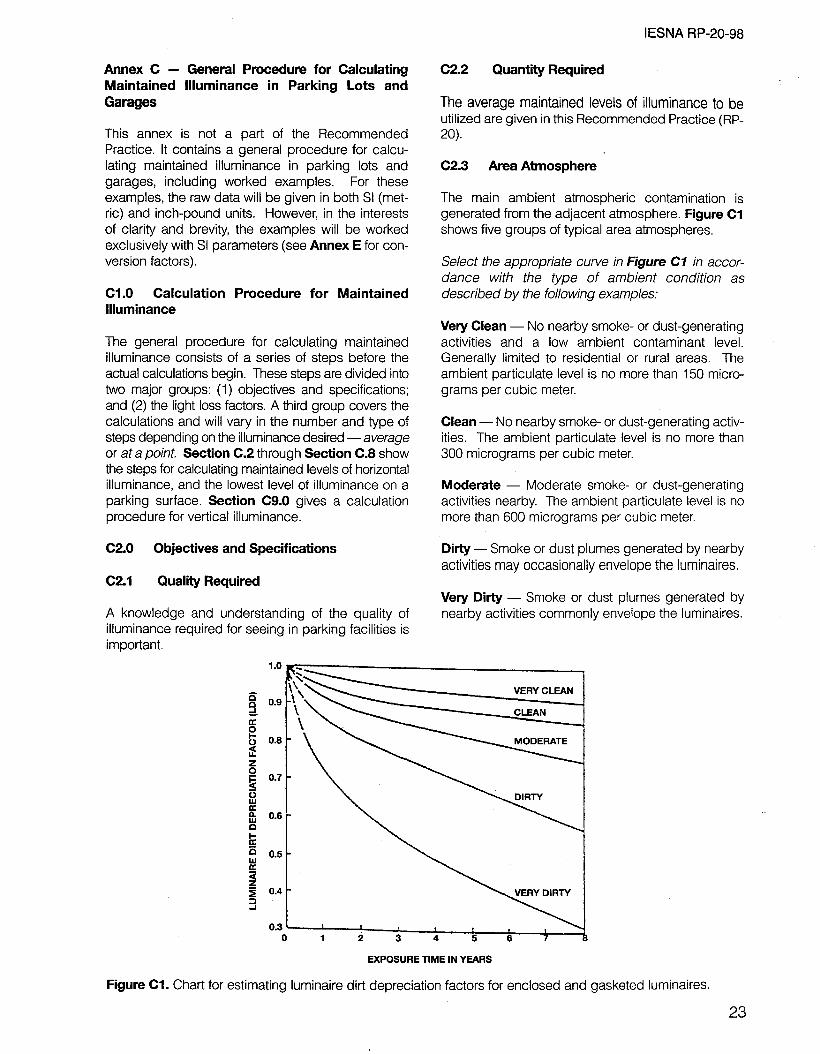
Annex C - General Procedure for Calculating Maintained Hluminance in Parking Lots and Garages
This annex is not a part of the Recommended Practice. It contains a general procedure for calcu- lating maintained illuminance in parking lots and garages, including worked examples. For these examples, the raw data will be given in both SI (met- ric) and inch-pound units. However, in the interests of clarity and brevity, the examples will be worked exclusively with SI parameters (see Annex E for con- version factors).
Cl.0 Calculation Procedure for Maintained llluminance
The general procedure for calculating maintained illuminance consists of a series of steps before the actual calculations begin. These steps are divided into two major groups: (1) objectives and specifications; and (2) the light loss factors. A third group covers the calculations and will vary in the number and type of steps depending on the illuminance desired -average or at a point Section C.2 through Section C.8 show the steps for calculating maintained levels of horizontal illuminance, and the lowest level of illuminance on a parking surface. Section C9.0 gives a calculation procedure for vertical illuminance.
C2.0 Objectives and Specifications
c2.1 Quality Required
A knowledge and understanding of the quality of illuminance required for seeing in parking facilities is important.
IESNA RP-20-98
c2.2 Quantity Required
The average maintained levels of illuminance to be utilized are given in this Recommended Practice (RP- 20).
C2.3 Area Atmosphere
The main ambient atmospheric contamination is generated from the adjacent atmosphere. Figure Cl shows five groups of typical area atmospheres.
Select the appropriate curve in Figure Cl in accor- dance with the type of ambient condition as described by the following examples:
Very Clean - No nearby smoke- or dust-generating activities and a low ambient contaminant level. Generally limited to residential or rural areas. The ambient particulate level is no more than 150 micro- grams per cubic meter.
Clean - No nearby smoke- or dust-generating activ- ities. The ambient particulate level is no more than 300 micrograms per cubic meter.
Moderate - Moderate smoke- or dust-generating activities nearby. The ambient particulate level is no more than 600 micrograms per cubic meter.
Dirty - Smoke or dust plumes generated by nearby activities may occasionally envelope the luminaires.
Very Dirty - Smoke or dust plumes generated by nearby activities commonly envelope the luminaires.
VERY CLEAN
0.3 1 9 4 * I \ 1 0 1 5 3 4 5 8 7
EXPOSURE TIME IN YEARS
Figure Cl. Chart for estimating luminaire dirt depreciation factors for enclosed and gasketed luminaires.
23

I ESNA RP-20-98
C2.4 Selection of Luminaire C3.4 Burnouts
Selection of the type of luminaire depends upon dimensions of the area, mounting height, luminaire dirt depreciation, lamp choice, maintenance consid- eration (including cleaning and lamp replacement), luminaire and installation appearance, color rendi- tion, and cost of equipment. All factors, whose rela- tive importance will vary from project to project, should be examined in detail first, then reviewed so that proper weights will be given to each one.
Unreplaced burned-out lamps will vary in quantity, depending on the kinds of lamps and the relamping program used. Manufacturers’ lamp mortality statis- tics should be consulted for the performance of each lamp type so that the number of burn-outs can be estemated before the time of planned replacement is reached. Practically, the quantity of lamp burnouts is determined by the quality of the lighting services pro- gram and by the physical performance of the pro- gram.
c3.0 Light Loss Factors (LLFs) C3.5 Equipment Factors (EFs)
Once the basic values discussed in Section C2.0 are established and a preliminary choice of a luminaire is made, light loss factors can be studied. Several of these factors - including one formerly known as maintenance factor - are the result of time-de- pendent depreciation effects to the original design. Others - such as equipment factor - will exist initially and continue through the life of the installation. However, all factors should be studied and reduced to the extent practical, because they will diminish the planned output of the lighting system.
c3.1 Maintenance Factor (MF)
Deprecated term no longer valid. See Section C3.0.
C3.2 Lamp Lumen Depreciation (LLD)
Information about the chosen lamp and its lumen depreciation are available from lamp manufacturers’ tables and graphs, Rated average useful life should be determined for specific hours per start. A typical parking lot lighting system will be in operation about 4,000 to 4,300 hours per year, if operated all night. Luminaires in above-ground garages will operate longer, while those in underground garage levels will operate full-time (nearly 8,800 hours per year). From these facts, a practical group relamping cycle should be established and then, based on the hours elapsed to lamp removal, the specific LLD factor can be determined. Consult manufacturers’ data or the latest ESNA Lighting Handbook for LLD factors.
C3.3 Luminaire Dirt Depreciation (LDD)
The accumulation of dirt on luminaires results in lost light output. This loss is known as the LDD factor and is determined by estimating the dirt category (very clean, clean, moderate, dirty, or very dirty) from defi- nitions given in Section C2.3 and Figure Cl. From the appropriate dirt condition curve in Figure Cl and the proper elapsed time in years of the planned cleaning cycle, the LDD factor is then found.
Light loss factors that are not dependent on time relate mostly to the specific equipment selected, and they usually have such little effect that correction is impractical. However, they can diminish the total light output of the system and should be minimized to the extent possible.
C3.6 Ambient Temperature
The effect of ambient temperature on the output of some lamps may be considerable. Each particular lamp-luminaire combination has its own distinctive characteristic of light output versus ambient tempe- rature. To apply a light loss factor due to ambient tem- perature, the designer must know the highest and low- est temperatures expected and obtain data showing variations in light output with changes in ambient tem- perature for the specific lamp and ballast to be used.
C3.7 Voltage
In-service voltage levels are difficult to predict, but high (or low) voltage at the luminaire will affect the light output of most lamps.
C3.8 Ballast Factor
The ballast factor of the ballast used in a production luminaire (fluorescent or high intensity discharge) can cause significant differences in light output when compared to the ballast used to generate the photo- metry of the luminaire in a photometric laboratory. The manufacturer should be consulted for these necessary factors.
C3.g Luminaire Surface Depreciation Factor
Surface depreciation results from adverse changes in a luminaire’s metal, paint, and plastic components and produces reduced light output.
Because of the complex relationship between the light-controlling elements of luminaires using more
24

IESNA RP-20-98
than one type of material it is difficult to predict loss- es due to deterioration. Also, for various luminaire surfaces, the losses will be differentially affected by the type of atmosphere to which each surface is exposed. No factors accounting for luminaire com- ponent depreciation are available at present.
C3.10 Change in Physical Surroundings
The designer should try and anticipate future changes that may affect surface conditions. In the design process, it is desirable to know when the pavement is in poor condition and if it is likely to be resurfaced early in the useful life of the lighting sys- tem. Consideration may also be given as to whether trees or border areas will be added, new buildings constructed nearby, or old buildings demolished.
C4.0 Total Light Loss Factor
The total light loss factor is obtained by multiplying together all the contributing factors just described. When certain factors are not known, or believed to be reasonably small, they are omitted. Otherwise, they are estimated based on past experience at similar locations. In all cases, a light loss factor should be used that at least considers the LLD and the LDD. At this point, if the total light loss factor estimate is excessive, it may be desirable to re-select the lumi- naire and/or lamp, or modify the cleaning and/or maintenance schedule.
C5.0 Calculations
llluminance calculations fall into three general types: (1) the determination of the average over an area; (2) the illuminance at a specific point on the surface; and (3) the uniformity of illuminance.
Calculations are based on luminaire photometric data curves that have been published in two formats. One method presents the data based on “per 1,000 lamp lumens’ of a specific lamp, and the other method is based on “rated initial lamp lumens” of a specific lamp.
C6.0 Determinations of Average llluminance
C6.1 General
The average illuminance over a large pavement area may be calculated by means of a “utilization curve,” or by computing the illuminance at a large number of specific points and averaging the values found. The utilization curve is a part of the data presented as a result of following LM-31-95, the ESNA Approved Method for Photometric Testing of Roadway Luminaires Using Incandescent Filament and High Intensity Discharge Lamps.
C6.2 Utilization Curves
Utilization curves, available for various types of lumi- naires, afford a practical method to determine average illuminance over the surface where lamp lumen out- put, mounting heights, width of paved area, and spacing between luminaires are known (or can be assumed). Conversely, the desired spacing - or any other unknown factor - may readily be determined if accurate data is available for all the other factors.
Figure C2 is an example of a utilization curve of a typical luminaire. Some manufacturers combine the utilization curve with the isolux curve and present both sets of curves on the same figure. The utilization curve indicates how much light falls on the surface, but reveals little about how light is distributed. Therefore, it should be used in conjunction with the isolux curve to evaluate the true performance of the luminaire, especially concerning compliance with the recommended uniformity ratios.
The total coefficient of utilization (CU) is the percentage of rated lamp lumens received on the horizontal using an area of given width and infinite length. The curves indicate the percentage of flux falling on the area in front of the luminaire (street side) and behind the luminaire (house side). Both areas are strip-like, of infinite length, with widths expressed as a ratio of width to mounting height. To obtain the total utilization for a given area, the CU for both the street side and the house side areas must be determined from the curves and then added. The luminaire is considered mounted as tested (level) and oriented over the reference line which divides the street side from the house side.
A calculation for average luminance illustrates the use of a utilization curve:
Given: the layout is as shown in Figure C3 with:
Staggered luminaire spacing 33 meters (108 ft.) Street width curb-to-curb 17 meters (66 ft.) Luminaire mounting height 10 meters (33 ft.) Luminaire overhang 2 meters (6.5 ft.) Luminaire dirt depreciation factor 0.70 Lamp (initial rating) 20,000 lumens Lamp lumen depreciation factor 0.85
Required:
Calculate the minimum average illuminance in lux for the given lot layout, (Note: Parking lots come in all shapes and sizes. Often multiple luminaires are attached to poles within the lot or down the center. This simplified example is intended to illustrate all of the principles involved).
25

IESNA RP-20-98
Solution (for average illuminance):
First, determine the coefficient of utilization for the “street-side” of the luminaire. To do this find the Ratiostreet-side from the following expression:
(Street width) - (Luminaire overhang)
(Luminaire mounting height)
Substituting numerical values from the given data:
Rati%tr@?t-side = (17 meters) - (2 meters)
(10 meters)
The COeffiCient of utilization for a RatiOstreeteside of 1.5 iS found to be 0.51 from Figure C2.
Next, determine the coefficient of utilization for the “house-side” of the luminaire. To do this find the Ratio housesi& from the following expression:
(Luminaire overhang)
(Luminaire mounting height)
Substituting numerical values from the given data:
Ratiohouse-side = (2 meters)
( 10 meters) = 0.2
The coefficient of utilization for a RatiohouseMside of 0.2 is found to be 0.05, again from Figure C2.
Therefore, the total coefficient (the “street-side” plus the “house-side”) is 0.56.
p ;4 i
5
0.50
0.40
0.30
0.2 1.5
TRANSVERSE WIDTH
RATIO = (STREET OR HOUSE SIDE)
LUMINAIRE MOUNTING HEIGHT
Figure C2. Example of Coefficient of Utilization (CU) curves for a luminaire providing medium semi-cutoff, Type II light distribution.
26

IESNA RP-20-98
The basic equation for determining average initial horizontal illuminance is:
EH(avg) = (Lamp Lumens)(CU)
ewv
Where: E~(~vg) = average initial horizontal illuminance in Iux
CU = Coefficient of Utilization
S = spacing between luminaires in meters
W = width of area in meters
A further modification of this equation is necessary to determine the average maintained horizontal iiluminance on the lot. For this calculation, which is indicative of the illuminance on the pavement when the illuminating source is at its lowest output and the luminaire is in its dirtiest condition, the equation is:
EM(avg) = (Lamp Lumens)(CU)(LLF)
ewJ)
Where: EM(avg) = average maintained horizontal illuminance in Iux
CU = Coefficient of Utilization
LLF = light loss factor = LDD x.LLD
S = spacing between luminaires in meters
W = width of area in meters
Note: The spacing between luminaires (S) is the longitudinal distance between luminaires if they are spaced in a staggered or one-sided arrangement. This distance is one-half the longitudinal distance between luminaires if the luminaires are arranged in opposite spacing.
Now the average illuminance in the area (and at the spacing) shown in Figure C3 can be found. Assume that Figure C2 was prepared using a 20,000-lumen
l 0 !z
I <CURB
t - --- 17M
(56 FV -- --_ c <CURB 0
- 33M t, t (108 m (2 Mm
STAGGERED LONGTUDINAL SPACING
10M MH = Mounting Height
- 15M
A 1.5MH
Figure C3. A luminaire and parking lot layout (assumed for typical computation) that uses a staggered arrangement of luminaires.
27

IESNA RP-20-98
lamp in the luminaire, and use the equation just given for calculating EMtavgj:
E~(avg) = (20,000)(0.56)(0.70)(0.65)
(33)(17) = 11.9lux
If average illuminance is the desired value (fractions of a Iux should be rounded to the nearest whole lux), it is also necessary to check whether the uniformity ratio is met. To do this, the illuminance at the lowest point on the lot must be calculated.
C7.0 Determination of the llluminance at a Specific Point
c7.1 General
The horizontal illuminance in Iux at a specific point may be determined from an “isolux” curve (Figure C4)
RATIO OF TRANSVERSE DISTANCE TO MOUNTING HEIGHT
or by means of the inverse square calculation method (see the latest edition of the /ESNA Lighting Hand- book). Since the isolux curve follows LM-31-95 (the IESNA Approved Method for Photometric Testing of Roadway Luminaires Using Incandescent Filament and High Intensity Discharge Lamps), this method will be discussed.
C7.2 lsolux Diagram
An isolux diagram is a graphical representation of points of equal illuminance connected by a continu- ous line. These lines may show lux values on a hori- zontal plane from a single unit having a definite mounting height, or they may show a composite picture of the illuminance from a number of sources arranged in any manner or at any mounting height. They are useful in the determination of the level of illu- minance at any specific point. In order to make these
STREET
I
HOUSE SIDE SIDE
LUMINAIRE POSITION VERTICAL ANGLES Y LUX UNDERNEATH
I-‘--- DIRECTION OF TRANSVERSE ROADWAY LINES ,----I
Mounting Height (m) 8 9 10 11 12 13 14 15
Mounting Height (ft.) . 26.2 29.5 32.8 36.1 39.4 42.6 45.9 49.2 Scaling Factor 1.27 1.00 0.81 0.67 0.56 0.48 0.41 0.86
Figure C4. Example of an isolux diagram of horizontal Iux on pavement surfaces for a luminaire providing a medium semi-cutoff, Type II light distribution (per 1,000 initial lamp lumens). The isolux data are based on a fuminaire mounting height of 9 meters (29.5 ft.). For other mounting heights, multiply the isolux data by the appropriate scaling factor. (See the scaling factor list below the isolux diagram.)
28

IESNA RP-20-98
curves applicable to all conditions, they are comput- ed for a given mounting height but horizontal dis- tances are expressed in ratios of the actual distance to the mounting height. Correction factors for other mounting heights are usually given in a tabulation alongside the curves.
To use the typical isolux diagram, the point on the pavement is located with respect to each luminaire in the system and the dimensions are determined in transverse and longitudinal multiples of the mounting height. The point is located on the isolux diagram (Figure C4) for each position it assumes with respect to a luminaire. The value of lux contributed by that luminaire is then estimated. If the isolux diagram is of the format based on “per 1,000 lamp lumens,” the total illuminance value must be multiplied by the ratio:
(Rated Lamp Lumens)/( 1000)
The total Iux contribution from at least the three near- est luminaires should be added together to obtain the total illuminance at a point.
To express the illuminance of the point in terms of maintained illuminance, multiply the initial value by the light loss factor.
The following example illustrates this calculation process, utilizing the layout shown in Figure C3, the roadway and depreciation factors (as used for the utilization curve and average Iux examples), and Figure C4.
Required: To determine the illuminance at point “A,” which is the total of contributions from luminaires 1,2, and 3.
Solution:
First the location of point “A” with respect to a point on the pavement directly under the luminaire is dimen- sioned in transverse and longitudinal multiples of the mounting height. Assume that the luminaire distribu- tion provides isolux lines as shown in Figure C4. Point ‘“A” is then located on this diagram for its position with respect to each luminaire.
Next, determine the contribution of luminaires 1 and 3 to point “A:”
Locate point “A” - Transverse 2 meters to “house side.” (2 meters)/(lO meters) = 0.2 times mounting height
Longitudinal 33 meters along pavement
(33 meters)/( 10 meters) = 3.3 times mounting height
At point “A” the estimated contribution is 0.08 Iux from each luminaire, uncorrected (value obtained from Figure C4). Therefore, luminaires 1 and 3 together provide 0.16 Iux (per an initial 1,000 lamp lumens).
Now determine the contribution of luminaire 2 to point ‘A:”
Locate point “A” - Transverse 15 meters to “street side.”
(15 meters)/( 10 meters) = 1.5 times mounting height
The longitudinal location is 0, directly across from the luminaire.
Therefore, at point “A” the estimated contribution from luminaire 2 is 0.17 Iux, uncorrected (value obtained from Figure C4).
Assuming initial l,OOO-lumen lamps are used, the total contribution at point “A” from the three luminaires is 0.16 + 0.17 = 0.33 lux. Because initial 20,000 lumen lamps are used, this contribution value must be multiplied by 20, to yield 6.6 lux. However, the subject luminaire mounting height is 10 meters, whereas the test lamp of Figure C4 is mounted at 9 meters. Thus it is necessary to correct the 6.6 Iux value. (To do this, multiply by 0.81, the correction factor given for a IO-meter mounting height given in Figure C4). The total contribution at point “A” thus becomes 0.81 x 6.6 = 5.3 lux.
The value of 5.3 lux assumes clean luminaires with lamps producing rated output. To express the contri- bution level in terms of Iux when the illuminating source is at its lowest output and when the luminaire is in its dirtiest condition, it is necessary to multiply the non-depreciated value (5.3 lux) by the LDD factor (0.7) and by the LLD factor (0.85). (Note: when multiplied together these depreciation factors become approximately 0.6.) Therefore, the fully corrected point “A” illuminance value is: 5.3 x 0.6 = 3.2 Iux. This is the value to compare with the calcu- lated, maintained (depreciated) average value of 12 Iux for the subject example, if average to minimum Iux is to be calculated.
(28.0 Uniformity Ratios
The illuminance uniformity requirements of this Practice should be determined by computing the uniformity ratio:
(Maximum Horizontal Lux)/(Minimum Horizontal Lux)
In the subject example, the maximum lux under the lamp as given in Figure C4 is 2 (assuming an initial 1 ,OOO-lumen lamp). For an initial 20,000-lumen lamp, the maximum lux under the lamp is: 2 x 20 = 40 Iux. Correcting for the lo-meter mounting height this becomes: 40 x 0.81 = 32 lux, then correcting for the
29

IESNA RP-20-98
combined maintenance factor this maximum lux value becomes: 32 x 0.6 = 19 Iux.
Using the lux value already calculated at point “A” for the contribution from luminaires 1, 2, and 3, the uni- formity ratio is 19/3.2 or 6:1, which is well within the maximum-to-minimum ratio requirements of RP-20, if point “A” is the minimum. A sufficient number of specific points over the area (in addition to point “A”) should be checked to ascertain accurately the loca- tion and value of the minimum point.
Again, using the subject example and checking point “B:”
Luminaire I (Figure C3) - Point “B” is 0.2 MH (mount- ing height) house-side and I$ the spacing, or 4.9 MH longitudinal. From Figure C4, the uncorrected illuminance value is 0.01 Iux.
Luminaire 2 - Point “B” is 1.5 MH street-side and $ the spacing, or 1.6 MH longitudinal. The uncorrected Figure C4 illuminance value is 0.09 lux.
Luminaire 3- Point “B” is 0.2 MH house-side and 1/2 the spacing, or 1.6 MH longitudinal. The uncorrected Figure C4 illuminance value is 0.5 Iux.
The total illuminance from all three luminaires is 0.01 + 0.09 + 0.50 = 0.60 lux (assuming initial l,OOO- lumen lamps). For initial 20,000-lumen lamps, the maximum lux is: 0.60 x 20 = 12 lux. Correcting for a IO-meter instead of g-meter mounting height gives 0.81 x 12 = 9.7 lux.
The final correction for lamp and dirt depreciation (using the combined factor of 0.6) is 0.6 x 9.7 = 5.8 Iux. Therefore, the maximum-to-minimum uniformity ratio at point “B” is 19/5.8 or 3.3: 1. This is lower (better uniformity) than the uniformity ratio calculated at point “A,” so point “A” remains the minimum lux point. If the uniformity ratio at point “A” (6:l) exceeds the designer’s desired value, the luminaire in the example design problem should not be utilized unless a greater mounting height can be used. For the IO-meter mounting height, a Type III distribution is probably preferable on this width of lot.
If the designer is using average illuminance calcula- tions, some manufacturers are now supplying curves of the type shown in Figure C5, which indicate the average-to-minimum Iux ratio for a particular arrangement of luminaires, as area width and spa- cing are varied. Such curves are a convenient aid to determine the average-to-minimum illuminance ratios for a given spacing and width, or to determine the permissible spacing for a desired uniformity ratio. They can also be used to determine the relationship between average illuminance and spacing and
width. Each different combination of luminaires, lamp type, lamp size, and arrangement of luminaires will produce a different set of these characteristic curves.
Cg.0 Vertical llluminance
The procedure for calculating vertical illuminance at a point and at a given elevation above the surface (e.g., 1.5 meters), can utilize much of the material presented in Section C8.0 for horizontal illuminance calculations, including use of isolux curves of hori- zontal illuminance. The mounting height (MH) of the luminaire is reduced by 1.5 meters to place the isolux curve on the same plane where the point of vertical illuminance is to be calculated. For the example given in Figure C3, the MH becomes 8.5 meters (10 minus 1.5). The actual lowest vertical reading will be just short of the next luminaire (luminaire 2 in Figure C3, when checking vertical illuminance from luminaire 1). However, the most critical point for vertical illumi- nance, from the personal security standpoint, is felt to be in the area of lowest horizontal illuminance - the “darkest” spot. This is point “A” in the Figure C3 layout. To calculate vertical illuminance at this point, proceed as follows:
l The longitudinal spacing is 33 meters (consider either luminaire 1 or 3). This is divided by the 8.5- meter MH to get the MH ratio: 33/8.5 = 3.9
l The lateral spacing is 2 meters (house side). This is divided by the 8.5 meter MH to get the MH ratio: 218.5 = 0.24
Entering Figure C4 at this point (0.24) and interpo- lating between the 0.02 and the 0.05 lines, gives an estimated value of 0.03 lux, uncorrected.
The horizontal value represents the cosine of the beam candela, and the sine represents the vertical. It is therefore necessary to calculate the angle to the point being checked. The diagonal, horizontal distance is equal to the hypotenuse of the triangle formed by the leg of the 2-meter overhang of luminaire 2 and the 33-meter spacing in the subject example. If “x” is the length of the hypotenuse, it is found from:
X = dw = 33 meters (rounded)
Then, by proportions:
(V)/(HL) = (MH)/(X)
Where: V = vertical lux
HL = horizontal lux
MH = mounting height for point 1.5 meters up X = horizontal hypotenuse
30

A MH correction is needed due to the difference between the calculation value of an 8.5meter MH and the Figure C4 diagram basis of a g-meter MH. This correction is based upon the inverse square law and is easily calculated. The correction is:
Therefore: 0.6 x 0.6 = 0.36 Iux. Finally, correcting for mounting height, 0.36 x 1.13 = 0.41 horizontal lux.
Using the proportion equation, the vertical Iux (V) at Point “A” from luminaire 1 is:
(9*)/(8.5*) = 81/72 = 1 .I3 V/(0.41) = (8.5)/(33); V = [(0.41)(8.5)]/33 = 0.11 Iux
The initial 0.03 Iux value (assuming l,OOO-lumen lamps) must be increased because in this case, 20,000-lumen lamps are used. Thus, 0.03 is multi- plied by 20, giving a value of 0.6 Iux. Correcting for depreciation, and again using the LDD factor of 0.7 and the LLD factor of 0.85, gives a multiplier of 0.6.
The !ow point also will receive vertical illuminance from iuminaire 2 at right angles to that produced by luminaire 1. An observer can be any place in the area bounded by the north curb (assume north to the top in Figure C3, upper part), the south curb and the east/west area between luminaires 1 and 2.
IESNA RP-20-98
13.7 M WIDTH (45
18.3 M WIDTH (60 FIJ
(4)
(98.4) (131.2) (1W (196.8) (229.6) (262.4)
SPACING BETWEEN LUMINAIRES IN METERS (FT)
5 & IT01 f
i 5TOl I I
d 6TOl 42.7 + 67.0 ww PW wm
SPACING BETWEEN LUMINAIRES IN METERS (FT)
Figure C5. These charts show average Iux (fc) versus luminaire spacing (top) and average-to-minimum unifor- mity ratios versus luminaire spacing (bottom) for a staggered luminaire arrangement. The values of average Iux (initial) are based on an initial lamp output of 30,000 lumens, and the ratio of average Iux to minimum Iux is the lowest value area. The luminaire distribution classification is medium semi-cutoff, Type II. Caution: While data taken from isolux diagrams may represent actual luminaire light output (as is shown in this figure), isolux data is most often presented as a value per 1,000 emitted lamp lumens.
31

IESNA RP-20-98
Therefore, it is felt appropriate to add the vertical illuminance from luminaire 2 to that of luminaire 1. This calculation involves the direct distance of 15 meters from the lower part of Figure C3 and use of the prior calculation of 0.17 horizontal Iux, uncorrected (see Section C7.2). Applying the correction factors (multiply by 20 to scale up to 20,000-lux lamps; multiply by 0.6 to account for all maintenance factors; and multiply by 1.13 to correct for the actual mounting height) gives 2.3 Iux horizontal. Using the proportion equation, the vertical Iux (V) at Point “A” from luminaire 2 is:
(V)/(2.3) = (8.5)/(K); V = 1.30 lux
The total vertical illuminance is 0.11 + 1.30 = 1.41 Iux. This is then compared with the value in the Standard Practice Table.
The basic principles for calculating vertical illumi- nance have just been presented. Many parking lot calculations will be more complex - for example, when using twin or quad luminaires on each pole, with a grid pattern layout. With such a configuration the lowest horizontal illuminance point will normally be in the midpoint of the rectangle. Up to four lumi- naires could contribute illuminance to this point from a quad luminaire. In this case the calculated Iux value would be doubled to yield the total vertical, as well as horizontal illuminance (see Annex 6).
32

I ESNA RP-20-98
Annex D - Visibility-Based Analysis of Parking the limit of readability of optotypes). These limits are Facility Lighting characterized by photometric values such as AL or VA.
This annex is not a part of the Recommended Practice. . . . . It contains a vrsrbrlrty based analysis of parking facility lighting.
Dl .O Introduction
The lighting recommendations in the previous edition of RP-20 as well as those in the current edition, rely primarily on i/luminance-based criteria -the amount of incident light falling on a surface or object. While illuminance-based criteria have served the lighting industry reasonably well, there has been a trend toward using luminance criteria for many types of facilities including roadway lighting. Substantial research has been conducted toward making small target visibility (STV) a potential criterion for roadway lighting. This annex uses current STV research as a basis for visibility-based lighting calculations for a typical visual task required in a parking facility and then relate these calculations to the illuminance criteria of Table 1 and Table 2 in the main document.
D2.0 Visibility Parameters
Parking facility lighting systems must provide ade- quate illuminance for the safe movement of vehicular and pedestrian traffic. Here the primary visual task is the timely detection of moving vehicles, pedestrians, and any obstacles that may represent a potential safety hazard. Curbs, wheel stops, posts, columns, and walls must be perceived sufficiently in advance of potential contact so that reaction and evasive action can take place in time to avoid impact.
Detection of an object is based upon adequate luminance contrast between the object and its background. The amount of luminance contrast required is a function of the adapted luminance, object size, object distance, speed (time of fixa- tion), contrast polarity (negative versus positive contrast), and the observer’s age. Since luminance = (illuminance x reflectance&, a relationship can be derived between luminance contrast (visibility) and illuminance. This relationship is based upon targets and backgrounds of known reflectance, assuming diffuse (Lambertian) surfaces.
Contrast, normally expressed by AL/L, consists of photometric units. Visibility is based on light sensa- tion. When a certain light level for a specified visual task is reached that evokes a sensation of visibility, the light level is called the “threshold value,” indicat- ing the threshold for perception. For basic visual functions this is indicated by the luminance differ- ence between the task and its background (example:
. . . . The calculations for vrsrbrlrty level (VL) presented here are based upon a visibility model that was first pub- lished in German in 1967, followed by an extended version written in English in 1981, 1987, and 1993. The model is based on the experimental data of Adrian, Aulhorn, Blackwell, Knoll and Tousey, Siendentopf et. al., and has long been used in Europe for calculating the visibility threshold of objects. After verification tests in Hendersonville, NC, it is now expected to be included in the next edition of IESNAIANSI RP-8 American National Standard Practice for Roadway Lighting.
There is also Blackwell’s model for VL (based on Blackwell-Taylor data) that holds for photopic lumi- nance only. These data are not compatible with Blackwell’s own data of 1946, which were recon- firmed and generally accepted.
The visibility model presented here reflects Blackwell’s 1946 data (Tiffany Study). However, this annex describes an extended model, developed by Dr. Werner Adrian and announced in his paper “The
. . Physiological Basis of the Vrsrbtlrty Concept” presented October 26-27, 1993 at the Second Annual Symposium on Visibility and llluminance in Roadway Lighting in Orlando, FL.*
Blackwell (1946) used the forced choice method and his data holds for 50 percent probability of seeing. Dr. Adrian and the other researchers just mentioned used a method by which luminance (L) was adjusted until a visibility threshold was reached.
As evidenced from the new data obtained by adjust- ment, the Blackwell data (1946) can be transformed into data corresponding to a 99.97 percent probability of seeing if a factor of 2.6 is used. The new data were found from laboratory experiments that covered the range from purely photopic levels down to near sco- topic leve!s. The results are also valid for the mesopic vision range.
The methodology proposed by Adrian and others con- sists of calculating the theoretical difference in lumi- nance required (between an object and its back- ground) so that an observer can perceive the object with a 99.9 percent “success rate” (probability), which is called the luminance difference threshold. The ratio of the actual luminance difference to the luminance difference threshold is called the visibility level (VL). The required visibility level is a function of the back- ground luminance and visual acuity required for the task.
*Sponsored by the Lighting Research Institute, New York, NY (Now the Lighting Research Office, EPRI, CA.)
33

IESNA RP-20-98
Since the majority of liability claims implicating park- ing facilities involve slips, trips, and falls, the visibility of curbs and/or wheel stops was investigated as a function of illuminance. The relevant visibility para- meters are discussed in the following sections.
D2.1 Reflectance
Calculations were performed for an unpainted con- crete curb (reflectance = 35 percent) on an asphalt pavement (reflectance = 7 percent), and on a dirty concrete floor (reflectance = 20 percent). Asphalt pavement is typically found on open-surface parking lots, while concrete floors are typicalty used in covered parking structures. These reflectance values are rep- resentative of measurements taken in numerous park- ing facilities.**
D2.2 Detection Distance
The distance at which a stationary object must be detected to avoid impact depends upon how fast the vehicle or pedestrian is moving, the percep-
**Original data gathered by Off-Roadway Facilities Subcommittee member D. R. Monahan.
103
g
102
s ‘0
u c 1 o-2
z
2 lo-3
2 m 1 o-4
tion-reaction time required to initiate evasive action, and the distance required to execute the evasive action. The typical vehicle speed in a parking facility is approximately 15 km/hr (9.3 miles/hr). The average pedestrian walking speed is approximately 4.7 km/hr (2.9 miles/hr). The per- ception-reaction time required is approximately one to two seconds.
Therefore, the perception-reaction distance is approxi- mately 5 to 10 meters (16.4 to 32.8 ft.) for a moving vehicle. To this must be added a stopping distance of approximately 3 meters (9.8 ft.) for a total distance of 8 to 13 meters (26.2 to 42.6 ft.). The perception-reaction distance for a pedestrian is approximately 2 to 3 meters (6.6 to 9.8 ft.). (The pedestrian can execute evasive action nearly instantaneously.) Therefore, the distance factor should be in the 3 to 13 meter (9.8 to 42.6 ft.) range. A consensus-value distance of 6 meters (19.7 ft.) has been used in these calculations. (This consen- sus value gives primary consideration to the percep- tion-reaction time needs of pedestrians.)***
***See ‘Desicion Sight Distance for Highway Design and Traffic Devices,” Federal Highway Administration, FHW A-RD- 78-78. Internet contact: chris.gaskins@fhwa. dot.gov
IA l&II I II III l\lI\~lAIJ I II III 15%1 l~oJ!/l\i,*o%l I I l I l
IY lusl \* I I I I I i 1 l\j I\ * \ / / / r CAtica:Lgle
after Blackwell -
Emin -Threshold
0.2 ) 0.5 1 1 21 ,151 !‘O,, , ’ L I i
1.3 2.5 ; lb 20 & io 80 io
Receptive Unit diameter (microns)
Figure Dl. Calculated critical angle a, (minarc) for 5, IO, and 20 percent deviation from Ricco’s Law expressed as EM,, = constant. The triangles are data of Blackwell. The second abscissa (microns) reflects the diameter of the receptive units over which spatial integration takes place.
34

IESNA RP-20-98
D2.3 Target Size D3.0 Analysis
The “target” object selected was a 15-cm by 1.8- meter (6-in. by 6-ft.) concrete wheel stop. This target is an elongated object with an approximate height-to- length ratio of 1 :12. The experiments underlying the small target visibility model utilize the angular size of concentrated targets (either round or square) of equal area and expressed in minutes of arc (minarc). This angle is formed by the diameter of the target and the distance from the target to the eye.
Discussions with Dr. Adrian indicate that conversions of odd-shaped targets can only be handled within the critical Ricco-angle. This angle specifies the reti- nal area in which spatial integration takes place. In Figure Di, Ricco’s critical angle is depicted for vari- ous background luminances. It reveals that where the background luminance (LB) equals 10-Z cd/m2 (0.9 10” cd/ft.*), the angular size over which integra- tion occurs measures around 3 minarc. This is far below the size of a wheel stop as seen from a distance of 3 to 13 meters (9.8 to 42.6 ft.). Therefore, only a part of a concrete curb’s horizontal extension (equal to about three times the height) is utilized and converted into a concentrated target of equal area. Though this target is also outside the Ricco angle, it allows a more accurate estimate. The equivalent target diameter is then 30 cm (11.8 in.) which, at a distance of 6 meters (19.7 ft.), results in a target size of 171 minarc.
02.4 Observation Time
Small target visibility (STV) research has found that the average fixation time of a target is between 0.1 and 0.2 seconds in daylight and 0.3 to 0.45 seconds at roadway lighting levels. Therefore, a value of 0.2 seconds is utilized for fixation time for parking facility lighting levels [2 Iux to 100 Iux (0.2 fc to 10 fc)], which are less than daylight levels but higher than roadway levels. The time factor increases the threshold lumi- nance difference by 2.03.
D2.5 Contrast Polarity Factor
Since the target (wheel stop) is brighter than the background (i.e., there is positive contrast), the contrast polarity factor is 1. (For discussion/determination of polarity factor, see Dr. Werner Adrian’s original research paper as described in Section D2.0)
D2.6 Age Factor
Calculations of the luminance difference required at illuminances ranging from 1 Iux to 200 Iux (0.1 fc to 20 fc) are indicated in Table Dl, and are plotted in Figure D2. The visibility levet (VL) required to allow a certain “form perception” level for various values of visual acuity (VA), is plotted versus the background luminance (La) in Figure 03.
Assuming diffuse (Lambertian) pavement surfaces, the background luminance (LB) was calculated from the illuminance based on an assumed reflectance of 20 percent for concrete pavement and an assumed reflectance of 7 percent for asphalt pavement.
The calculated curve of visibility level (VL) versus increasing illuminance for a concrete wheel stop on an asphalt pavement is shown in Figure D4. Overlaid on this curve are plots of (1) the required VL for VA = 0.66 and (2) the required VL for VA = 0.8. The inter- section of each required VL plot with the calculated VL curve indicates the minimum illuminance required for visibility of the wheel stop. These minimum illumi- nances are approximately 1.6 Iux (0.16 fc) when the VA = 0.66 and approximately 4.5 Iux (0.45 fc) when the VA = 0.8.
,
Similarly, the calculated curve of VL versus increasing illuminance for a concrete wheel stop on a concrete pavement is shown in Figure D5. Applying the graphical method of curve intersections just described, it is found that when VA = 0.66 the minimum illuminance required for visibility is approximately 4 Iux (0.4 fc) and when VA = 0.8 the minimum illuminance required for visibility is approximately 11 lux (1.1 fc).
Most open parking lots are constructed with asphalt pavement, where the RP-20 minimum illuminance level (see Table 1) is 2 Iux (0.2 fc). Most garage floors are of concrete, where the RP-20 minimum illumi- nance level (see Table 2) is 10 Iux (1 fc). Therefore, a visibility-based calculation of the minimum illumi- nance (i.e., an intersection value from Figure D4 or Figure D5) needed to make concrete wheel stops visible (at normal viewing distance) compares favorably with the consensus values arrived at by members of the RP-20 subcommittee.
The luminance difference threshold is adjusted for a 60-year-old observer. This adjustment factor is calcu- lated to be 1.77. (For discussion/determination of age-related adjustment factor, see Dr. Werner Adrian’s original research paper as described in Section 020)
35

IESNA RP-20-98
Table Dl: Visibility-Based Analysis of Parking Facility Lighting
Visibility calculations are based upon Werner Adrian’s formula for Delta L (AL) with adjustment factors for time of observation, contrast polarity factor, and age of observer. Observation time is taken as 0.2 seconds based on current research for parking facility lighting levels. The distance from the object to the observer of 6 meters (19.7 ft) represents a practical balance between driver Visibility as one pulls into a stall, and pedestrian visibility walking between vehicles. The size of the object is 15 cm (5.9 in) high by 1.8 meters (5.9 ft.) long, which represents a typical precast concrete wheel stop. Reflectance values are based upon field measurements of a random sample of parking facilities.
ASPHALT PAVEMENT
Itluminance llluminance Pavement Object Background Target Delta L Delta L Visibility Required Required
footcandles Iux Reflectance Reflectance Luminance Luminance Actual Threshold Level VL
(cd/m*) (cd/m21 (VAE.66) (VA=O.8)
0.095 1.00 0.07 0.350 0.022 0.111 0.089 0.003 27 35 85
0.189 2.00 0.07 0.350 0.045 0.223 0.178 0.005 36 30 75
0.284 3.00 0.07 0.350 0.067 0.334 0.267 0.006 42 25 62
0.379 4.00 0.07 0.350 0.089 0.446 0.357 0.008 47 21 52
0.473 5.00 0.07 0.350 0.111 0.557 0.446 0.009 52 20 48
0.568 6.00 0.07 0.350 0.134 0.668 0.535 0.010 56 19 44
0.663 7.00 0.07 0.350 0.156 0.780 0.624 0.011 59 18 41
0.758 8.00 0.07 0.350 0.178 0.891 0.713 0.011 62 17 38
0.852 9.00 0.07 0.350 0.201 1.003 0.802 0.012 65 16 36
0.947 10.00 0.07 0.350 0.223 1.114 0.891 0.013 68 15
1.042 11.00 0.07 0.350 0.245 1.225 0.980 0.014 70
1.136 12.00 0.07 0.350 0.267 1.337 1.070 0.015 72
1.231 13.00 0.07 0.350 0.290 1.448 1.159 0.016 75
1.326 14.00 0.07 0.350 0.312 1.560 1.248 0.016 77
1.420 15.00 0.07 0.350 0.334 1.671 1.337 0.017 79
1.515 16.00 0.07 0.350 0.357 1.783 1.426 0.018 81
1.610 17.00 0.07 0.350 0.379 1.894 1.515 0.018 82
1.705 18.00 0.07 0.350 0.401 2.005 1.604 0.019 84
1.799 19.00 0.07 0.350 0.423 2.117 1.693 0.020 86
1.894 20.00 0.07 0.350 0.446 2.228 1.783 0.020 88
2.367 25.00 0.07 0.350 0.557 2.785 2.228 0.023 95
2.841 30.00 0.07 0.350 0.668 3.342 2.674 0.027 100
3.314 35.00 0.07 0.350 0.780 3.899 3.119 0.031 102
3.788 40.00 0.07 0.350 0.891 4.456 3.565 0.035 103
4.261 45.00 0.07 0.350 1.003 5.013 4.011 0.038 104
4.735 50.00 0.07 0.350 1.114 5.570 4.456 0.042 106
5.682 60.00 0.07 0.350 1.337 6.685 5.348 0.050 108
6.629 70.00 0.07 0.350 1.560 7.799 6.239 0.057 109
7.576 80.00 0.07 0.350 1.783 8.913 7.130 0.064 111
8.523 90.00 0.07 0.350 2.005 10.027 8.021 0.072 112
9.470 100.00 0.07 0.350 2.228 11.141 8.913 0.079 113
18.939 200.00 0.07 0.350
Note: Multiply cd/m* data by O.@?S to get cd/K2 data.
4.456 22.282 17.825 0.148 121
36

IESNA RP-20-98
Table Dl: (continued) Visibility-Based Analysis of Parking Facility Lighting
CONCRETE FLOOR
lliuminance llluminance Pavement Object Background Target Delta L Delta L Visibility Required Required
footcandles Iux Reflectance Reflectance Luminance Luminance Actual Threshold Level
(cd/m*) (cd/m21 ("f266) (vnv=LO.S)
0.095 0.189
0.284
0.379
0.473
0.568
0.663
0.758
0.852
0.947
1.042
1.136
1.231
1.326
1.420
1.515
1.610
1.705
1.799 i '
1.894
2.367
2.841
3.314
3.788
4.261
4.735
5.682
6.629
7.576
8.523
9.470
1 .oo 0.200
2.00 0.200
3.00 0.200
4.00 0.200
5.00 0.200
6.00 0.200
7.00 0.200
8.00 0.200
9.00 0.200
10.00 0.200
11.00 0.200
12.00 0.200
13.00 0.200
14.00 0.200
15.00 0.200
16.00 0.200
17.00 0.200
18.00 0.200
19.00 0.200
20.00 0.200
25.00 0.200
30.00 0.200
35.00 0.200
40.00 0.200
45.00 0.200
50.00 0.200
60.00 0.200
70.00 0.200
80.00 0.200
90.00 0.200
100.00 0.200
18.939 200.00 0.200
0.350
0.350
0.350
0.350
0.350
0.350
0.350
0.350
0.350
0.350
0.350
0.350
0.350
0.350
0.350
0.350
0.350
0.350
0.350
0.350
0.350
0.350
0.350
0.350
0.350
0.350
0.350
0.350
0.350
0.350
0.350
0.350
0.064 0.111 0.048 0.006
0.127 0.223 0.095 0.009
0.191 0.334 0.143 0.012
0.255 0.446 0.191 0.014
0.318 0.557 0.239 0.016
0.382 0.668 0.286 0.018
0.446 0.780 0.334 0.020
0.509 0.891 0.382 0.022
0.573 1.003 0.430 0.024
0.637 1.114 0.477 0.026
0.700 1.225 0.525 0.028
0.764 1.337 0.573 0.030
0.828 1.448 0.621 0.032
0.891 1.560 0.668 0.035
0.955 1.671 0.716 0.037
1.019 1.783 0.764 0.039
1.082 1.894 0.812 0.041
1.146 2.005 0.859 0.043
1.210 2.117 0.907 0.045
1.273 2.228 0.955 0.048
1.592 2.785 1.194 0.058
1.910 3.342 1.432 0.069
2.228 3.899 1.671 0.079
2.546 4.456 1.910 0.089
2.865 5.013 2.149 0.099
3.183 5.570 2.387 0.109
3.820 6.685 2.865 0.129
4.456 7.799 3.342 0.148
5.093 8.913 3.820 0.167
5.730 10.027 4.297 0.186
6.366 11.141 4.775 0.205
12.732 22.282 9.549 0.387
8
10
12
13
14
15
16
17
18
19
19
19
19
19
19
20
20
20
20
20
21
21
21
21
22
22
22
23
23
23
23
25
28
20
17
14
12
11
10.5
9.7
9
8.5
8
Note: Multiply cd/m2 databy0.0929to getcdlft2 data.
60
45
35
30
27
24
22
21
20
19.5
18.8
17.7
17
16
15
14
37

I ESNA RP-20-98
30 = $ 70
a 60 A 5 50
. 3 40 a,
rl I _ : 9 Asphalt Pavement (Reflectance = 7%)
m i 0 Concrete Pavement (Reflectance = 20%)
Distance = 6 m (20 ft.) Wheel Stop Reflectance = 35%
Figure D2. Visibility of concrete wheel stops for a 60-year-old observer.
50
5 > 20 3
$ 10 .- .v, >
5
1
I PARAMETER:
I
VISUAL ACUITY (mid).
56 6 ,, , I *t .I
2 34666 2 3 4 56*;1 0.1 1 10
Background Luminance of the Target, LB (cd/m2)
Figure D3. Derived visibility levels (VLs) required in street lighting for different levels of form perception. In the background luminance (Ls) range of 0.2 to 0.6, VLs of 20 to 40 appear to be necessary to provide form perception relating to a visual acuity (VA) of 0.8.
38

IESNA RP-20-98
60 5 L -I 50 A .= E s 40 .- >
u Calculated VL
l Required VL (VA = 0.8) 30 A Calculated VL (VA = 0.66)
20 7.
10 ’ 0 1 2 3 4 5 6 7 8 9 10
1.1) (.2) (.3) (.4) 65) (-6) l-7) (-8) W (1)
Illuminance, lux (fc)
Notes: 60-year-old observer at a distance of 6 meters (19.7 ft.) Reflectances: Curb = 35%, Asphalt = 7%
Figure D4. Required illuminance for visibility of a concrete curb (wheel stop) on an asphalt pavement. .,.
R Calculated VL
+ Required VL (VA = 0.8)
Required VL (VA = 0.86)
0 2 4 6 8 10 12 14 16 18 20 (.2) (.4) (.6) (.8) (1.0) (1.2) (1.4) (1.6) (1.8) (2)
Illuminance, lux (fc)
Notes: 60-year-old observer at a distance of 6 meters (19.7 ft.) Reflectances: Curb = 35%, Floor = 20%
Figure D5. Required illuminance for visibility of a concrete curb (wheel stop) on a concrete pavement. 39

IESNA RP-20-98
Annex E- SI (Metric) Conversions
This annex is not a part of the Recommended Practice. It contains useful conversion factors for translating data between the SI (metric) and inch-pound (English) measurement systems.
During the service life of this Recommended Practice, use of the SI system in North America is expected to expand. The following “rounded” factors are appropriate for most conversions involving the inch-pound system. This is because the SI quantities given in most text, tables, and figures typically do not have precision beyond two significant figures. When making conversions, it is important that the product not imply a greater accuracy than existed in the original dimension or quantity. However, certain applications (such as structures) may require that conversions be performed with great precision. Conversion factors for such purposes are given in parentheses.
Length Area
1 inch = 25 mm (25.4) 1 inch = 2.5 cm (2.54) 1 foot = 0.3 m (0.3048) 1 yard = 0.91 m (0.914)
/
1 mile = 1.6 km (1.61)
1 square inch = 6.5 cm2 (6.452) 1 square foot = 0.09 m2 (0.0929)
,l square yard = 0.84 m2 (0.836) 1 acre = 0.4 hectares (0.405)
Mass Volume
1 cubic inch = 16 cm3 (16.39) 1 cubic foot = 0.028 m3 (0.02831) 1 cubic yard = 0.77 m3 (0.7645) 1 quart = 0.95 liters (0.9463) 1 gallon = 3.8 liters (3.785)
Speed
1 foot/second = 0.3 m/second (0.3048) 1 mile/hour = 1.6 km/hour (1.609)
Temperature
Convert degrees Fahrenheit (“F) to degrees Celsius (“C): “C = 5/9(“F - 32)
Convert degrees Celsius (“C) to degrees Fahrenheit (“F): “F = 9/5(“C) + 32
1 ounce = 28 (28.34) g 1 pound = 0.45 kg (0.454) 1 ton = 900 kg (907)
Light
1 footcandle = 1 l lux (10.76) 1 footlambert = 3.4 candela/m2 (3.42)
For conversions between other units refer to the American Society of Testing and Materials (1916 Race Street, Philadelphia, PA 19103) Standard for Metric Practice E 380.
Source: Box, Paul C.; Units of Measure: Overcoming the Metric/English Barrier, ITE Journal, Institute of Transportation Engineers, Washington, D.C., 1989.
40

NOTES

NOTES