routable/routed protocols a routed protocol allows the router to forward data between nodes on...
TRANSCRIPT
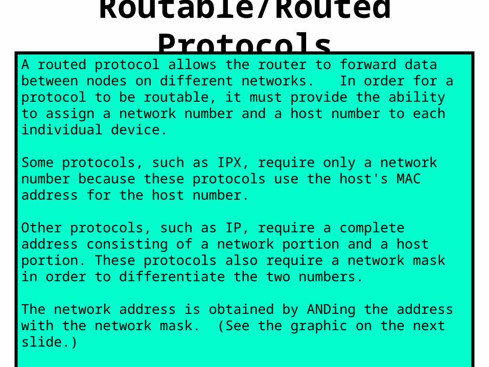
Routable/Routed ProtocolsA routed protocol allows the router to forward data between nodes on different networks. In order for a protocol to be routable, it must provide the ability to assign a network number and a host number to each individual device.
Some protocols, such as IPX, require only a network number because these protocols use the host's MAC address for the host number.
Other protocols, such as IP, require a complete address consisting of a network portion and a host portion. These protocols also require a network mask in order to differentiate the two numbers.
The network address is obtained by ANDing the address with the network mask. (See the graphic on the next slide.)
The reason that a network mask is used is to allow groups of sequential IP addresses to be treated as a single unit. If this grouping were not allowed, each host would have to be mapped individually for routing.

Finding the Network Address with ANDingBy ANDing the Host address of 192.168.10.2 with 255.255.255.0 (its network mask) we obtain the network address of 192.168.10.0

IP is a Routed ProtocolThe Internet Protocol (IP) is the most widely used implementation of a hierarchical network-addressing scheme.
IP is a connectionless, unreliable, best-effort delivery protocol.
The term connectionless means that no dedicated circuit connection is established prior to transmission as there is when placing a telephone call.
IP determines the most efficient route for data based on the routing protocol.
The terms unreliable and best-effort do not imply that the system is unreliable and does not work well, but that IP does not verify that the data reached its destination. This function is handled by the upper layer protocols.
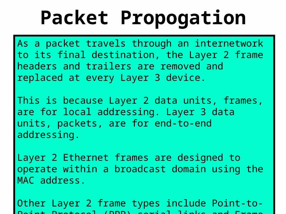
Packet PropogationAs a packet travels through an internetwork to its final destination, the Layer 2 frame headers and trailers are removed and replaced at every Layer 3 device.
This is because Layer 2 data units, frames, are for local addressing. Layer 3 data units, packets, are for end-to-end addressing.
Layer 2 Ethernet frames are designed to operate within a broadcast domain using the MAC address.
Other Layer 2 frame types include Point-to-Point Protocol (PPP) serial links and Frame Relay connections, which use different Layer 2 addressing schemes.

Connectionless/Connection OrientedTwo types of delivery services are connectionless and connection-oriented.
These two services provide the actual end-to-end delivery of data in an internetwork.
Most network services use a connectionless delivery system.
Different packets may take different paths to get through the network, but are reassembled after arriving at the destination.
In a connectionless system, the destination is not contacted before a packet is sent. A good comparison for a connectionless system is a postal system.
In connection-oriented systems, a connection is established between the sender and the recipient before any data is transferred. An example of a connection-oriented network is the telephone system.

Packet Switched / Circuit SwitchedConnectionless network processes are often referred to as packet switched processes.
As the packets pass from source to destination, packets can switch to different paths, and possibly arrive out of order. Devices make the path determination for each packet based on a variety of criteria. Some of the criteria, such as available bandwidth, may differ from packet to packet.
Connection-oriented network processes are often referred to as circuit switched processes.
A connection with the recipient is first established, and then data transfer begins. All packets travel sequentially across the same physical or virtual circuit.
The Internet is a gigantic, connectionless network in which all packet deliveries are handled by IP.
TCP adds Layer 4, connection-oriented reliability services to IP.
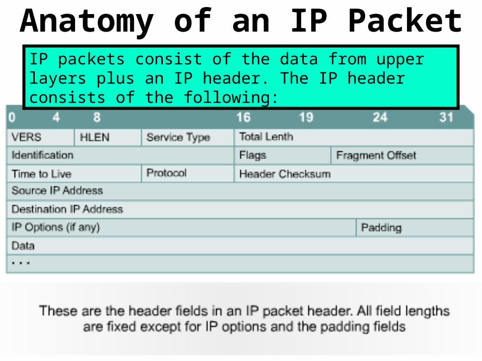
Anatomy of an IP PacketIP packets consist of the data from upper layers plus an IP header. The IP header consists of the following:
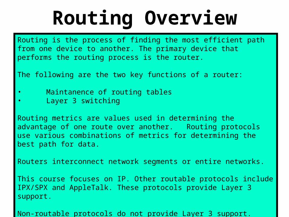
Routing OverviewRouting is the process of finding the most efficient path from one device to another. The primary device that performs the routing process is the router.
The following are the two key functions of a router:
• Maintanence of routing tables• Layer 3 switching
Routing metrics are values used in determining the advantage of one route over another. Routing protocols use various combinations of metrics for determining the best path for data.
Routers interconnect network segments or entire networks.
This course focuses on IP. Other routable protocols include IPX/SPX and AppleTalk. These protocols provide Layer 3 support.
Non-routable protocols do not provide Layer 3 support.
The most common non-routable protocol is NetBEUI.
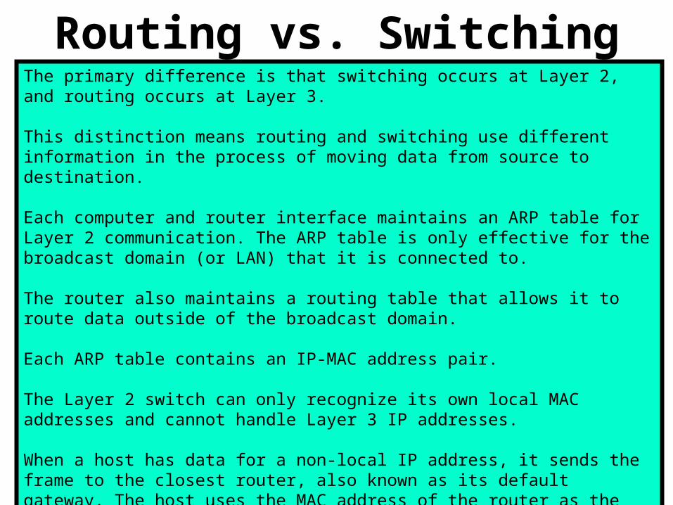
Routing vs. SwitchingThe primary difference is that switching occurs at Layer 2, and routing occurs at Layer 3.
This distinction means routing and switching use different information in the process of moving data from source to destination.
Each computer and router interface maintains an ARP table for Layer 2 communication. The ARP table is only effective for the broadcast domain (or LAN) that it is connected to.
The router also maintains a routing table that allows it to route data outside of the broadcast domain.
Each ARP table contains an IP-MAC address pair.
The Layer 2 switch can only recognize its own local MAC addresses and cannot handle Layer 3 IP addresses.
When a host has data for a non-local IP address, it sends the frame to the closest router, also known as its default gateway. The host uses the MAC address of the router as the destination MAC address.
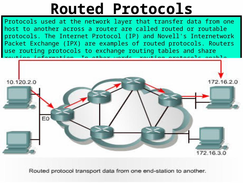
Routed ProtocolsProtocols used at the network layer that transfer data from one host to another across a router are called routed or routable protocols. The Internet Protocol (IP) and Novell's Internetwork Packet Exchange (IPX) are examples of routed protocols. Routers use routing protocols to exchange routing tables and share routing information. In other words, routing protocols enable routers to route routed protocols.
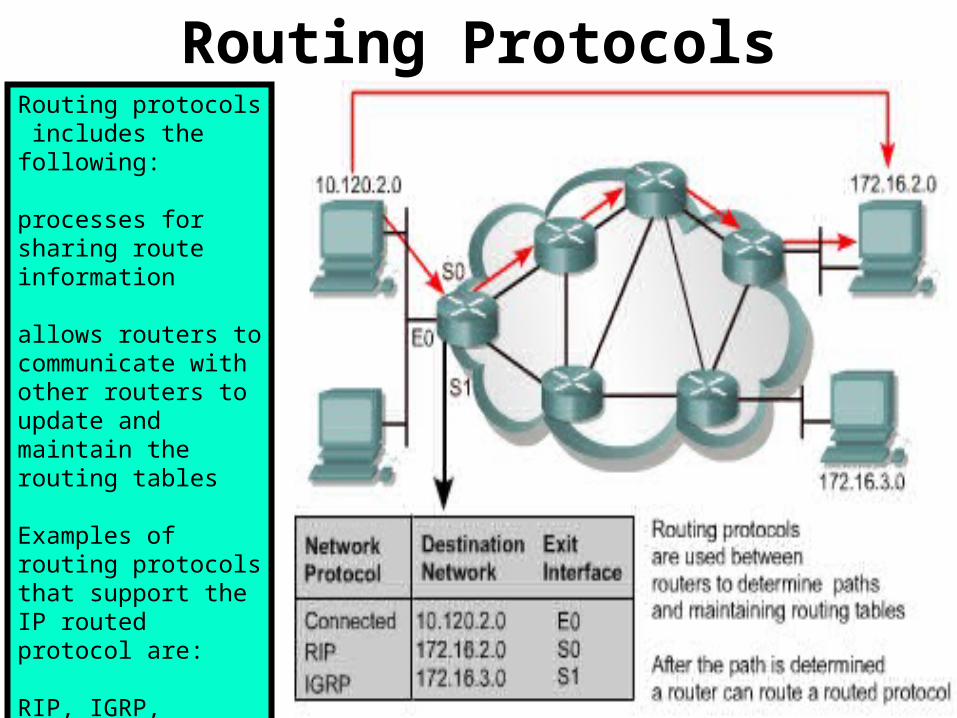
Routing ProtocolsRouting protocols includes the following:
processes for sharing route information
allows routers to communicate with other routers to update and maintain the routing tables
Examples of routing protocols that support the IP routed protocol are:
RIP, IGRP, OSPF, BGP, and EIGRP.

Path DeterminationPath determination occurs at the network layer.
Path determination enables a router to compare the destination address to the available routes in its routing table, and to select the best path.
The routers learn of these available routes through static routing or dynamic routing.
Routes configured manually by the network administrator are static routes.
Routes learned by others routers using a routing protocol are dynamic routes.
The router uses path determination to decide which port an incoming packet should be sent out of to travel on to its destination.
This process is also referred to as routing the packet.
Each router that the packet encounters along the way is called a hop.
The hop count is the distanced traveled.
Similarly, routers can make decisions based on the load, bandwidth, delay, cost, and reliability of a network link.
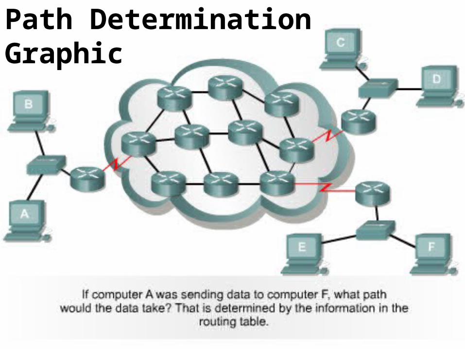
Path DeterminationGraphic
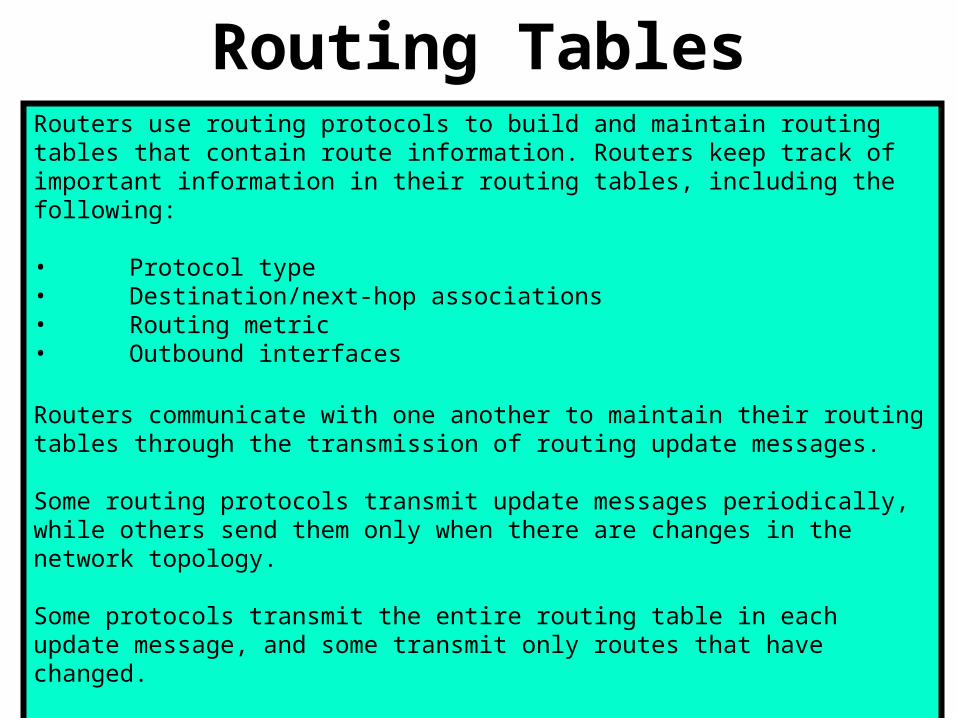
Routing TablesRouters use routing protocols to build and maintain routing tables that contain route information. Routers keep track of important information in their routing tables, including the following:
• Protocol type• Destination/next-hop associations• Routing metric• Outbound interfaces
Routers communicate with one another to maintain their routing tables through the transmission of routing update messages.
Some routing protocols transmit update messages periodically, while others send them only when there are changes in the network topology.
Some protocols transmit the entire routing table in each update message, and some transmit only routes that have changed.
By analyzing the routing updates from the neighboring routers, a router builds and maintains its routing table.
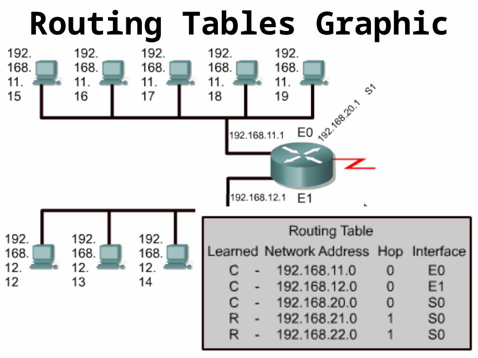
Routing Tables Graphic

Routing Algorithms and MetricsAn algorithm is a detailed solution to a problem.
In the case of routing packets, different routing protocols use different algorithms to decide which port an incoming packet should be sent to.
Routing algorithms depend on metrics to make these decisions.
Routing protocols often have one or more of the following design goals:
• Optimization • Simplicity and low overhead• Robustness and stability• Flexibility • Rapid convergence

Routing Metrics Graphics

IGP and EGPAn autonomous system is a network or set of networks under common administrative control, such as the cisco.com domain.

Link State & Distance VectorIGPs can be further categorized as either distance-vector or link-state protocols.
The distance-vector routing approach determines the distance and direction, vector, to any link in the internetwork.
Examples of distance-vector protocols are RIP, IGRP and EIGRP:
Link-state routing protocols were designed to overcome limitations of distance vector routing protocols. Link-state routing protocols respond quickly to network changes sending trigger updates only when a network change has occurred.
Examples of link-state protocols include OSPF and IS-IS.

Routing Protocols - RIPRIP is a distance vector routing protocol that uses hop count as its metric.
Because hop count is the only routing metric used by RIP, it does not always select the fastest path to a destination.
Also, RIP cannot route a packet beyond 15 hops.
RIP Version 1 (RIPv1) requires that all devices in the network use the same subnet mask, because it does not include subnet mask information in routing updates. This is also known as classful routing.
RIP Version 2 (RIPv2) provides prefix routing, and does send subnet mask information in routing updates. This is also known as classless routing.
With classless routing protocols, different subnets within the same network can have different subnet masks. The use of different subnet masks within the same network is referred to as variable-length subnet masking (VLSM).

Routing Protocols - IGRPIGRP is a distance-vector routing protocol developed by Cisco.
IGRP was developed specifically to address problems associated with routing in large networks that were beyond the range of protocols such as RIP.
IGRP can select the fastest available path based on delay, bandwidth, load, and reliability.
IGRP also has a much higher maximum hop count limit than RIP.
IGRP uses only classful routing.
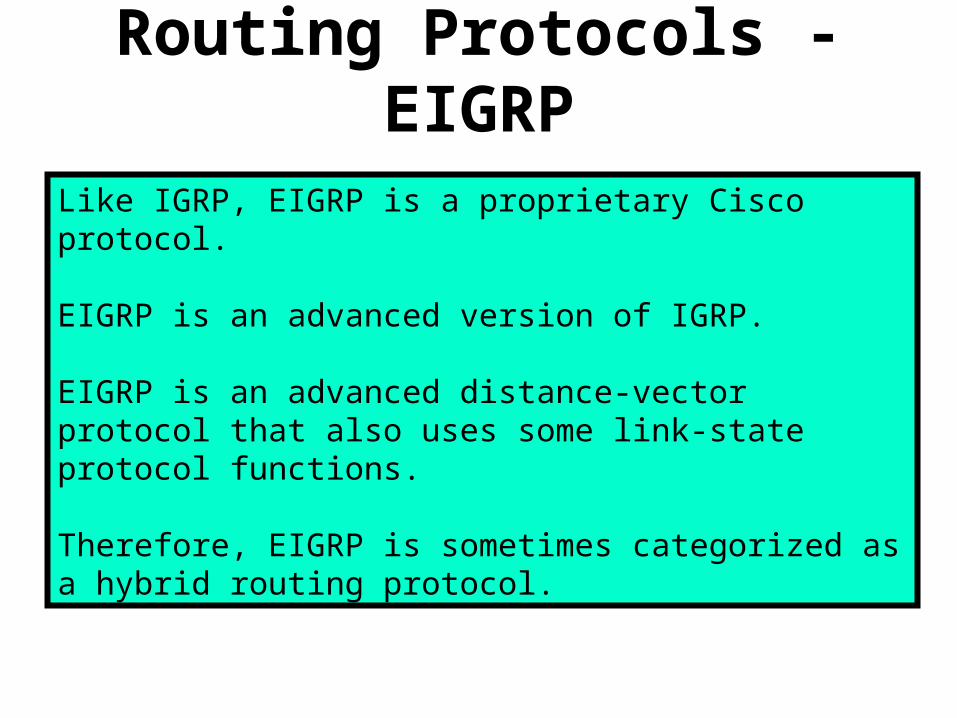
Routing Protocols - EIGRP
Like IGRP, EIGRP is a proprietary Cisco protocol.
EIGRP is an advanced version of IGRP.
EIGRP is an advanced distance-vector protocol that also uses some link-state protocol functions.
Therefore, EIGRP is sometimes categorized as a hybrid routing protocol.

Routing Protocols - OSPF
OSPF is a link-state routing protocol developed by the Internet Engineering Task Force (IETF) in 1988.
OSPF was written to address the needs of large, scalable internetworks that RIP could not.
While EIGRP may be easier to configure, it only works on Cisco routers.
OSPF does not have that limitation.
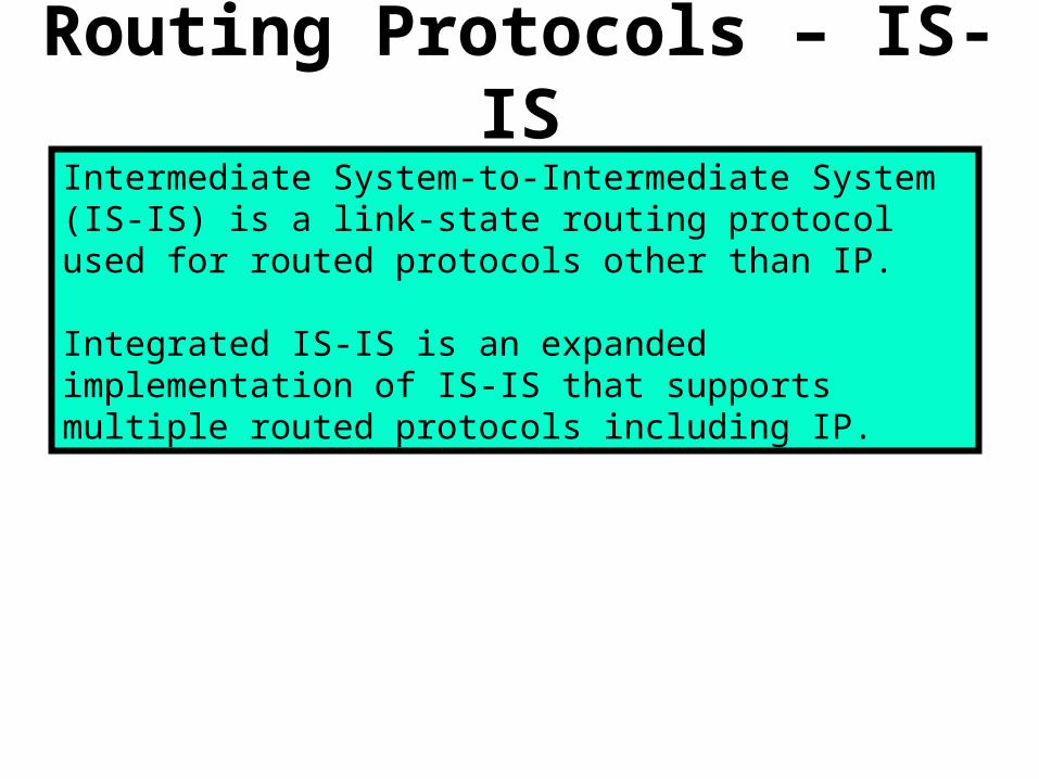
Routing Protocols – IS-ISIntermediate System-to-Intermediate System (IS-IS) is a link-state routing protocol used for routed protocols other than IP.
Integrated IS-IS is an expanded implementation of IS-IS that supports multiple routed protocols including IP.

Routing Protocols – BGPBorder Gateway Protocol (BGP) is an example of an External Gateway Protocol (EGP).
BGP exchanges routing information between autonomous systems while guaranteeing loop-free path selection.
BGP is the principal route advertising protocol used by major companies and ISPs on the Internet.
BGP4 is the first version of BGP that supports classless interdomain routing (CIDR) and route aggregation.
Unlike common Internal Gateway Protocols (IGPs), such as RIP, OSPF, and EIGRP, BGP does not use metrics like hop count, bandwidth, or delay.
Instead, BGP makes routing decisions based on network policies, or rules using various BGP path attributes.

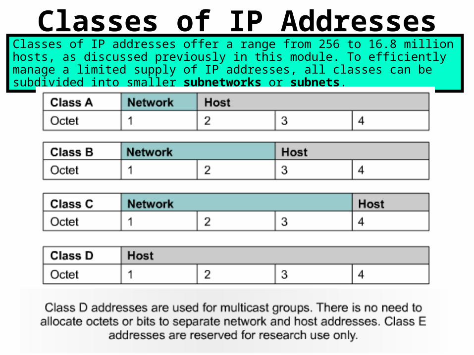
Classes of IP AddressesClasses of IP addresses offer a range from 256 to 16.8 million hosts, as discussed previously in this module. To efficiently manage a limited supply of IP addresses, all classes can be subdivided into smaller subnetworks or subnets.

Introduction to SubnettingTo create the subnet structure, host bits must be reassigned as network bits.
This is often referred to as ‘borrowing’ bits.
However, a more accurate term would be ‘lending’ bits.
The starting point for this process is always the leftmost host bit, the one closest to the last network octet.
Subnet addresses include the Class A, Class B, and Class C network portion, plus a subnet field and a host field.
The subnet field and the host field are created from the original host portion of the major IP address.
This is done by assigning bits from the host portion to the original network portion of the address.
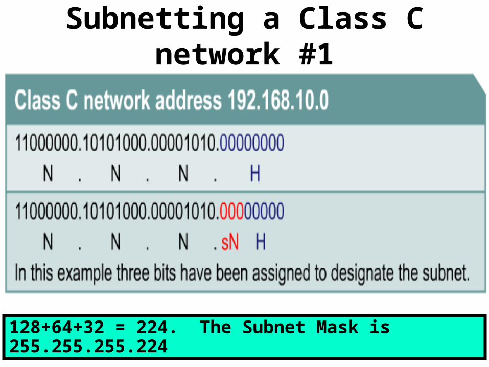
Subnetting a Class C network #1
128+64+32 = 224. The Subnet Mask is 255.255.255.224
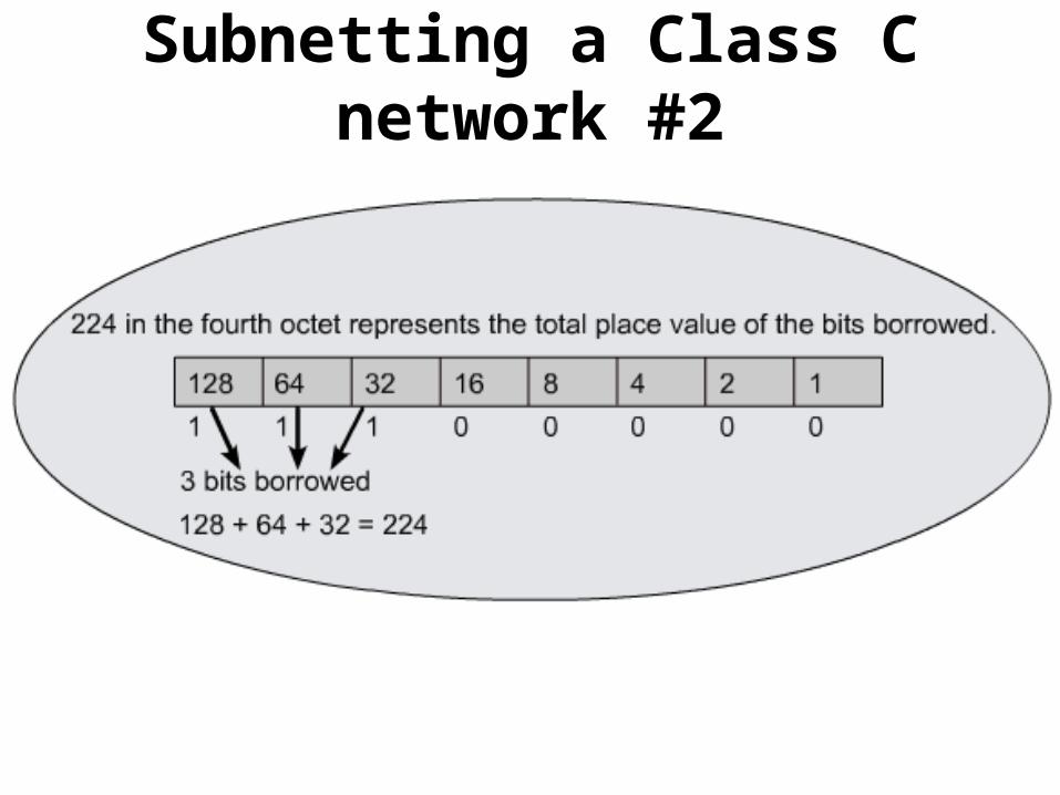
Subnetting a Class C network #2
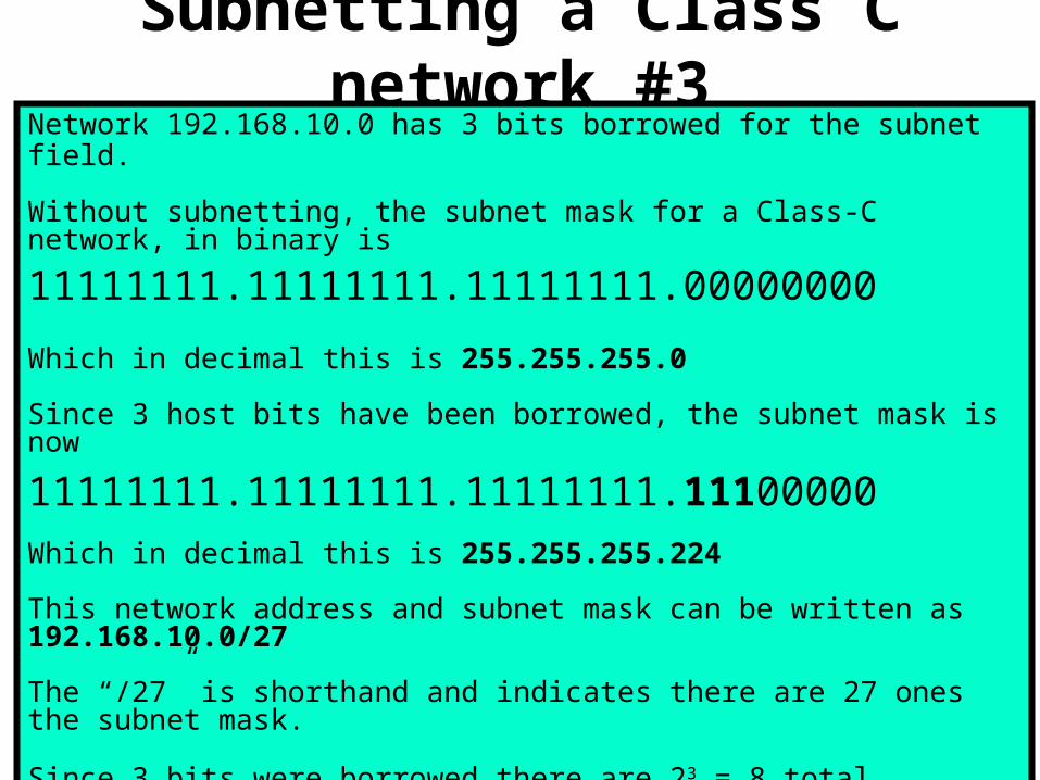
Subnetting a Class C network #3Network 192.168.10.0 has 3 bits borrowed for the subnet field.
Without subnetting, the subnet mask for a Class-C network, in binary is
11111111.11111111.11111111.00000000
Which in decimal this is 255.255.255.0
Since 3 host bits have been borrowed, the subnet mask is now
11111111.11111111.11111111.11100000
Which in decimal this is 255.255.255.224
This network address and subnet mask can be written as 192.168.10.0/27
The “/27” is shorthand and indicates there are 27 ones the subnet mask.
Since 3 bits were borrowed there are 23 = 8 total subnets. (-2 = 6 usable)
Since 5 bits remain there are 25 = 32 addresses per subnet. (-2 = 30 usable)

Subnetting a Class C network #4In 192.168.10.0/27 the 8 subnets of 32 would look like this:
The first address in every subnet is the network address for that subnet.The last address in every subnet is the broadcast address for that subnet.
Since Subnet 0 has the same network addresses as the entire 192.168.10.0 network, it is unusable. Since the last subnet has the same broadcast addresses as the entire 192.168.10.0 network, it is also unusable.
For this reason, you need to subtract 2 when computing USABLE subnets.
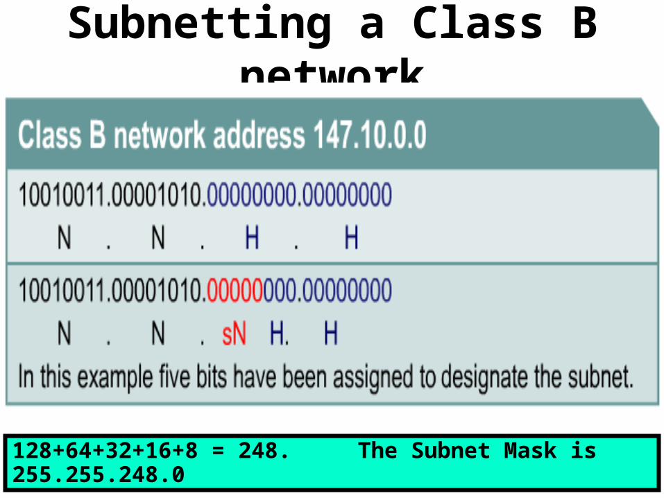
Subnetting a Class B network
128+64+32+16+8 = 248. The Subnet Mask is 255.255.248.0

Subnetting a Class A network #1
128+64+32+16 = 240. The Subnet Mask is 255.240.0.0
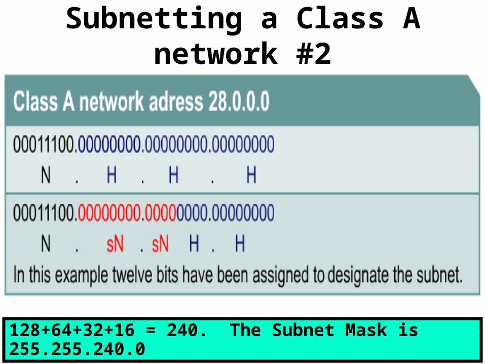
Subnetting a Class A network #2
128+64+32+16 = 240. The Subnet Mask is 255.255.240.0
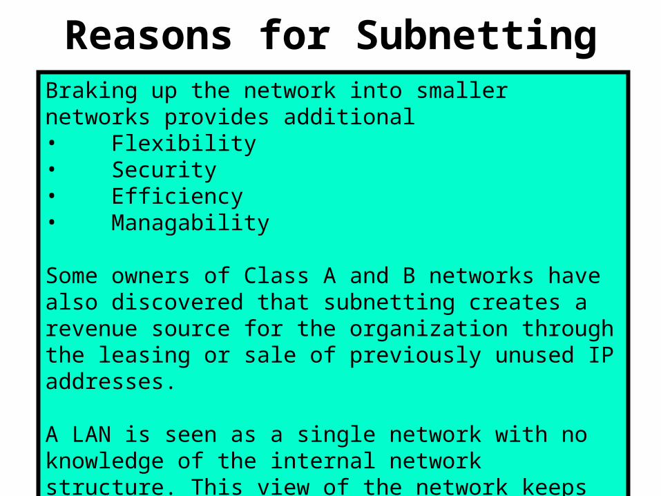
Reasons for SubnettingBraking up the network into smaller networks provides additional• Flexibility• Security• Efficiency• Managability
Some owners of Class A and B networks have also discovered that subnetting creates a revenue source for the organization through the leasing or sale of previously unused IP addresses.
A LAN is seen as a single network with no knowledge of the internal network structure. This view of the network keeps the routing tables small and efficient.