transparent or routed firewall mode - cisco.com or routed firewall mode...
TRANSCRIPT
Transparent or Routed Firewall Mode
This chapter describes how to set the firewall mode to routed or transparent, as well as how the firewallworks in each firewall mode.
You can set the firewall mode independently for each context in multiple context mode.
• About the Firewall Mode, page 1
• Default Settings, page 7
• Guidelines for Firewall Mode, page 8
• Set the Firewall Mode, page 9
• Examples for Firewall Mode, page 9
• History for the Firewall Mode, page 20
About the Firewall ModeThe ASA supports two firewall modes: Routed Firewall mode and Transparent Firewall mode.
About Routed Firewall ModeIn routed mode, the ASA is considered to be a router hop in the network. Each interface that you want to routebetween is on a different subnet. You can share Layer 3 interfaces between contexts.
About Transparent Firewall ModeTraditionally, a firewall is a routed hop and acts as a default gateway for hosts that connect to one of itsscreened subnets. A transparent firewall, on the other hand, is a Layer 2 firewall that acts like a “bump in thewire,” or a “stealth firewall,” and is not seen as a router hop to connected devices. However, like any otherfirewall, access control between interfaces is controlled, and all of the usual firewall checks are in place.
Layer 2 connectivity is achieved by using a "bridge group" where you group together the inside and outsideinterfaces for a network, and the ASA uses bridging techniques to pass traffic between the interfaces. Eachbridge group includes a Bridge Virtual Interface (BVI) to which you assign an IP address on the network.
CLI Book 1: Cisco ASA Series General Operations CLI Configuration Guide, 9.4 1

You can have multiple bridge groups for multiple networks. In transparent mode, these bridge groups cannotcommunicate with each other.
Using the Transparent Firewall in Your NetworkThe ASA connects the same network between its interfaces. Because the firewall is not a routed hop, you caneasily introduce a transparent firewall into an existing network.
The following figure shows a typical transparent firewall network where the outside devices are on the samesubnet as the inside devices. The inside router and hosts appear to be directly connected to the outside router.
Figure 1: Transparent Firewall Network
About Bridge GroupsA bridge group is a group of interfaces that the ASA bridges instead of routes. Bridge groups are only supportedin Transparent FirewallMode. Like any other firewall interfaces, access control between interfaces is controlled,and all of the usual firewall checks are in place.
Bridge Virtual Interface (BVI)
Each bridge group includes a Bridge Virtual Interface (BVI). The ASA uses the BVI IP address as the sourceaddress for packets originating from the bridge group. The BVI IP address must be on the same subnet as thebridge group member interfaces. The BVI does not support traffic on secondary networks; only traffic on thesame network as the BVI IP address is supported.
Only bridge group member interfaces are named and can be used with interface-based features.
CLI Book 1: Cisco ASA Series General Operations CLI Configuration Guide, 9.42
Transparent or Routed Firewall ModeAbout Transparent Firewall Mode
Bridge Groups in Transparent Firewall Mode
Bridge group traffic is isolated from other bridge groups; traffic is not routed to another bridge group withinthe ASA, and traffic must exit the ASA before it is routed by an external router back to another bridge groupin the ASA. Although the bridging functions are separate for each bridge group, many other functions areshared between all bridge groups. For example, all bridge groups share a syslog server or AAA serverconfiguration. For complete security policy separation, use security contexts with one bridge group in eachcontext.
You can include multiple interfaces per bridge group. See Guidelines for Firewall Mode, on page 8 for theexact number of bridge groups and interfaces supported. If you use more than 2 interfaces per bridge group,you can control communication between multiple segments on the same network, and not just between insideand outside. For example, if you have three inside segments that you do not want to communicate with eachother, you can put each segment on a separate interface, and only allow them to communicate with the outsideinterface. Or you can customize the access rules between interfaces to allow only as much access as desired.
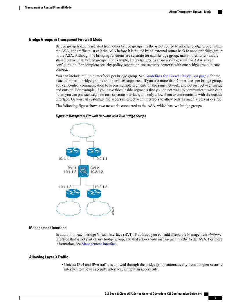
The following figure shows two networks connected to the ASA, which has two bridge groups.
Figure 2: Transparent Firewall Network with Two Bridge Groups
Management Interface
In addition to each Bridge Virtual Interface (BVI) IP address, you can add a separate Management slot/portinterface that is not part of any bridge group, and that allows only management traffic to the ASA. For moreinformation, see Management Interface.
Allowing Layer 3 Traffic
• Unicast IPv4 and IPv6 traffic is allowed through the bridge group automatically from a higher securityinterface to a lower security interface, without an access rule.
CLI Book 1: Cisco ASA Series General Operations CLI Configuration Guide, 9.4 3
Transparent or Routed Firewall ModeAbout Transparent Firewall Mode

• For Layer 3 traffic traveling from a low to a high security interface, an access rule is required on thelow security interface.
• ARPs are allowed through the bridge group in both directions without an access rule. ARP traffic canbe controlled by ARP inspection.
• IPv6 neighbor discovery and router solicitation packets can be passed using access rules.
• Broadcast and multicast traffic can be passed using access rules.
Allowed MAC Addresses
The following destination MAC addresses are allowed through the bridge group if allowed by your accesspolicy (see Allowing Layer 3 Traffic, on page 3). Any MAC address not on this list is dropped.
• TRUE broadcast destination MAC address equal to FFFF.FFFF.FFFF
• IPv4 multicast MAC addresses from 0100.5E00.0000 to 0100.5EFE.FFFF
• IPv6 multicast MAC addresses from 3333.0000.0000 to 3333.FFFF.FFFF
• BPDU multicast address equal to 0100.0CCC.CCCD
• AppleTalk multicast MAC addresses from 0900.0700.0000 to 0900.07FF.FFFF
Passing Traffic Not Allowed in Routed Mode
In routed mode, some types of traffic cannot pass through the ASA even if you allow it in an access rule. Thebridge group, however, can allow almost any traffic through using either an access rule (for IP traffic) or anEtherType rule (for non-IP traffic):
• IP traffic—In routed firewall mode, broadcast and multicast traffic is blocked even if you allow it in anaccess rule, including unsupported dynamic routing protocols and DHCP (unless you configure DHCPrelay). Within a bridge group, you can allow this traffic with an access rule (using an extended ACL).
• Non-IP traffic—AppleTalk, IPX, BPDUs, and MPLS, for example, can be configured to go throughusing an EtherType rule.
The bridge group does not pass CDP packets packets, or any packets that do not have a valid EtherTypegreater than or equal to 0x600. An exception is made for BPDUs and IS-IS, which are supported.
Note
BPDU Handling
To prevent loops using the Spanning Tree Protocol, BPDUs are passed by default.To block BPDUs, you needto configure an EtherType rule to deny them. If you are using failover, you might want to block BPDUs toprevent the switch port from going into a blocking state when the topology changes. See Transparent FirewallMode Bridge Group Requirements for Failover for more information.
CLI Book 1: Cisco ASA Series General Operations CLI Configuration Guide, 9.44
Transparent or Routed Firewall ModeAbout Transparent Firewall Mode
MAC Address vs. Route Lookups
For traffic within a bridge group, the outgoing interface of a packet is determined by performing a destinationMAC address lookup instead of a route lookup.
Route lookups, however, are necessary for the following situations:
• Traffic originating on the ASA—Add a default/static route on the ASA for traffic destined for a remotenetwork where a syslog server, for example, is located.
• Voice over IP (VoIP) and TFTP traffic with inspection enabled, and the endpoint is at least one hopaway—Add a static route on the ASA for traffic destined for the remote endpoint so that secondaryconnections are successful. The ASA creates a temporary "pinhole" in the access control policy to allowthe secondary connection; and because the connection might use a different set of IP addresses than theprimary connection, the ASA needs to perform a route lookup to install the pinhole on the correctinterface.
Affected applications include:
◦CTIQBE
◦GTP
◦H.323
◦MGCP
◦RTSP
◦SIP
◦Skinny (SCCP)
◦SunRPC
◦TFTP
• Traffic at least one hop away for which the ASA performs NAT—Configure a static route on the ASAfor traffic destined for the remote network. You also need a static route on the upstream router for trafficdestined for the mapped addresses to be sent to the ASA.
CLI Book 1: Cisco ASA Series General Operations CLI Configuration Guide, 9.4 5
Transparent or Routed Firewall ModeAbout Transparent Firewall Mode

This routing requirement is also true for embedded IP addresses for VoIP and DNS with inspection andNAT enabled, and the embedded IP addresses are at least one hop away. The ASA needs to identify thecorrect egress interface so it can perform the translation.
Figure 3: NAT Example: NAT within a Bridge Group
Unsupported Features for Bridge Groups in Transparent Mode
The following table lists the features are not supported in bridge groups in transparent mode.
Table 1: Unsupported Features in Transparent Mode
DescriptionFeature
—Dynamic DNS
CLI Book 1: Cisco ASA Series General Operations CLI Configuration Guide, 9.46
Transparent or Routed Firewall ModeAbout Transparent Firewall Mode
DescriptionFeature
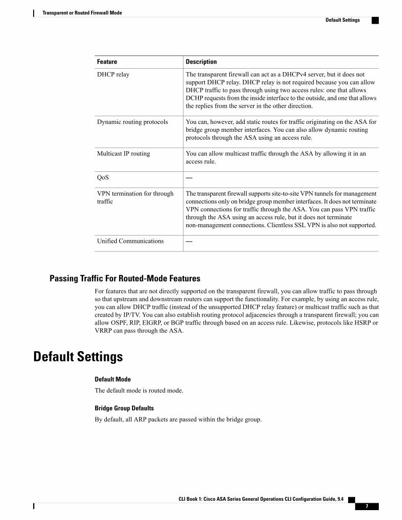
The transparent firewall can act as a DHCPv4 server, but it does notsupport DHCP relay. DHCP relay is not required because you can allowDHCP traffic to pass through using two access rules: one that allowsDCHP requests from the inside interface to the outside, and one that allowsthe replies from the server in the other direction.
DHCP relay
You can, however, add static routes for traffic originating on the ASA forbridge group member interfaces. You can also allow dynamic routingprotocols through the ASA using an access rule.
Dynamic routing protocols
You can allow multicast traffic through the ASA by allowing it in anaccess rule.
Multicast IP routing
—QoS
The transparent firewall supports site-to-site VPN tunnels for managementconnections only on bridge group member interfaces. It does not terminateVPN connections for traffic through the ASA. You can pass VPN trafficthrough the ASA using an access rule, but it does not terminatenon-management connections. Clientless SSL VPN is also not supported.
VPN termination for throughtraffic
—Unified Communications
Passing Traffic For Routed-Mode FeaturesFor features that are not directly supported on the transparent firewall, you can allow traffic to pass throughso that upstream and downstream routers can support the functionality. For example, by using an access rule,you can allow DHCP traffic (instead of the unsupported DHCP relay feature) or multicast traffic such as thatcreated by IP/TV. You can also establish routing protocol adjacencies through a transparent firewall; you canallow OSPF, RIP, EIGRP, or BGP traffic through based on an access rule. Likewise, protocols like HSRP orVRRP can pass through the ASA.
Default SettingsDefault Mode
The default mode is routed mode.
Bridge Group Defaults
By default, all ARP packets are passed within the bridge group.
CLI Book 1: Cisco ASA Series General Operations CLI Configuration Guide, 9.4 7
Transparent or Routed Firewall ModeDefault Settings

Guidelines for Firewall ModeContext Mode Guidelines
Set the firewall mode per context.
Bridge Group Guidelines (Transparent Mode)
• You can create up to 250 bridge groups, with 4 interfaces per bridge group.
• Each directly-connected network must be on the same subnet.
• The ASA does not support traffic on secondary networks; only traffic on the same network as the BVIIP address is supported.
• For IPv4, an IP address for the BVI is required for each bridge group for both management traffic andfor traffic to pass through the ASA. IPv6 addresses are supported, but not required for the BVI.
• You can only configure IPv6 addresses manually.
• The BVI IP address must be on the same subnet as the connected network. You cannot set the subnetto a host subnet (255.255.255.255).
• Management interfaces are not supported as bridge group members.
• In transparent mode, you must use at least 1 bridge group; data interfaces must belong to a bridge group.
• In transparent mode, do not specify the BVI IP address as the default gateway for connected devices;devices need to specify the router on the other side of the ASA as the default gateway.
• In transparent mode, the default route, which is required to provide a return path for management traffic,is only applied to management traffic from one bridge group network. This is because the default routespecifies an interface in the bridge group as well as the router IP address on the bridge group network,and you can only define one default route. If you have management traffic from more than one bridgegroup network, you need to specify a regular static route that identifies the network from which youexpect management traffic.
• In transparent mode, PPPoE is not supported for the Management interface.
Additional Guidelines and Limitations
•When you change firewall modes, the ASA clears the running configuration because many commandsare not supported for both modes. The startup configuration remains unchanged. If you reload withoutsaving, then the startup configuration is loaded, and the mode reverts back to the original setting. SeeSet the Firewall Mode, on page 9 for information about backing up your configuration file.
• If you download a text configuration to the ASA that changes the mode with the firewall transparentcommand, be sure to put the command at the top of the configuration; the ASA changes the mode assoon as it reads the command and then continues reading the configuration you downloaded. If thecommand appears later in the configuration, the ASA clears all the preceding lines in the configuration.See Set the ASA Image, ASDM, and Startup Configuration for information about downloading textfiles.
CLI Book 1: Cisco ASA Series General Operations CLI Configuration Guide, 9.48
Transparent or Routed Firewall ModeGuidelines for Firewall Mode

Set the Firewall ModeThis section describes how to change the firewall mode.
We recommend that you set the firewall mode before you perform any other configuration because changingthe firewall mode clears the running configuration.
Note
Before You Begin
When you change modes, the ASA clears the running configuration (see Guidelines for Firewall Mode, onpage 8 for more information).
• If you already have a populated configuration, be sure to back up your configuration before changingthe mode; you can use this backup for reference when creating your new configuration. See Back Upand Restore Configurations or Other Files.
• Use the CLI at the console port to change the mode. If you use any other type of session, including theASDMCommand Line Interface tool or SSH, you will be disconnected when the configuration is cleared,and you will have to reconnect to the ASA using the console port in any case.
• Set the mode within the context.
To set the firewall mode to transparent and also configure ASDMmanagement access after the configurationis cleared, see Configure ASDM Access.
Note
Procedure
Set the firewall mode to transparent:firewall transparent
Example:
ciscoasa(config)# firewall transparent
To change the mode to routed, enter the no firewall transparent command.
You are not prompted to confirm the firewall mode change; the change occurs immediately.Note
Examples for Firewall ModeThis section includes examples of how traffic moves through the ASA in the routed and transparent firewallmode.
CLI Book 1: Cisco ASA Series General Operations CLI Configuration Guide, 9.4 9
Transparent or Routed Firewall ModeSet the Firewall Mode

How Data Moves Through the ASA in Routed Firewall ModeThe following sections describe how datamoves through the ASA in routed firewall mode inmultiple scenarios.
An Inside User Visits a Web ServerThe following figure shows an inside user accessing an outside web server.
Figure 4: Inside to Outside
The following steps describe how data moves through the ASA:
1 The user on the inside network requests a web page from www.example.com.
2 The ASA receives the packet and because it is a new session, it verifies that the packet is allowed accordingto the terms of the security policy.
For multiple context mode, the ASA first classifies the packet to a context.
3 The ASA translates the real address (10.1.2.27) to the mapped address 209.165.201.10, which is on theoutside interface subnet.
The mapped address could be on any subnet, but routing is simplified when it is on the outside interfacesubnet.
CLI Book 1: Cisco ASA Series General Operations CLI Configuration Guide, 9.410
Transparent or Routed Firewall ModeHow Data Moves Through the ASA in Routed Firewall Mode
4 The ASA then records that a session is established and forwards the packet from the outside interface.
5 When www.example.com responds to the request, the packet goes through the ASA, and because thesession is already established, the packet bypasses the many lookups associated with a new connection.The ASA performs NAT by untranslating the global destination address to the local user address, 10.1.2.27.
6 The ASA forwards the packet to the inside user.
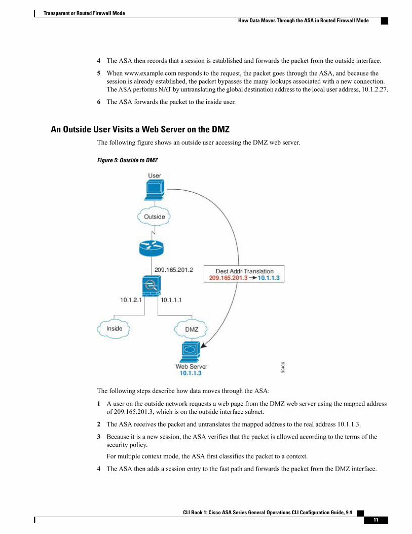
An Outside User Visits a Web Server on the DMZThe following figure shows an outside user accessing the DMZ web server.
Figure 5: Outside to DMZ
The following steps describe how data moves through the ASA:
1 A user on the outside network requests a web page from the DMZ web server using the mapped addressof 209.165.201.3, which is on the outside interface subnet.
2 The ASA receives the packet and untranslates the mapped address to the real address 10.1.1.3.
3 Because it is a new session, the ASA verifies that the packet is allowed according to the terms of thesecurity policy.
For multiple context mode, the ASA first classifies the packet to a context.
4 The ASA then adds a session entry to the fast path and forwards the packet from the DMZ interface.
CLI Book 1: Cisco ASA Series General Operations CLI Configuration Guide, 9.4 11
Transparent or Routed Firewall ModeHow Data Moves Through the ASA in Routed Firewall Mode

5 When the DMZ web server responds to the request, the packet goes through the ASA and because thesession is already established, the packet bypasses the many lookups associated with a new connection.The ASA performs NAT by translating the real address to 209.165.201.3.
6 The ASA forwards the packet to the outside user.
An Inside User Visits a Web Server on the DMZThe following figure shows an inside user accessing the DMZ web server.
Figure 6: Inside to DMZ
The following steps describe how data moves through the ASA:
1 A user on the inside network requests a web page from the DMZ web server using the destination addressof 10.1.1.3.
2 The ASA receives the packet and because it is a new session, the ASA verifies that the packet is allowedaccording to the terms of the security policy.
For multiple context mode, the ASA first classifies the packet to a context.
3 The ASA then records that a session is established and forwards the packet out of the DMZ interface.
4 When the DMZ web server responds to the request, the packet goes through the fast path, which lets thepacket bypass the many lookups associated with a new connection.
CLI Book 1: Cisco ASA Series General Operations CLI Configuration Guide, 9.412
Transparent or Routed Firewall ModeHow Data Moves Through the ASA in Routed Firewall Mode

5 The ASA forwards the packet to the inside user.
An Outside User Attempts to Access an Inside HostThe following figure shows an outside user attempting to access the inside network.
Figure 7: Outside to Inside
The following steps describe how data moves through the ASA:
1 A user on the outside network attempts to reach an inside host (assuming the host has a routable IP address).
If the inside network uses private addresses, no outside user can reach the inside network without NAT.The outside user might attempt to reach an inside user by using an existing NAT session.
2 The ASA receives the packet and because it is a new session, it verifies if the packet is allowed accordingto the security policy.
3 The packet is denied, and the ASA drops the packet and logs the connection attempt.
If the outside user is attempting to attack the inside network, the ASA employs many technologies todetermine if a packet is valid for an already established session.
CLI Book 1: Cisco ASA Series General Operations CLI Configuration Guide, 9.4 13
Transparent or Routed Firewall ModeHow Data Moves Through the ASA in Routed Firewall Mode

A DMZ User Attempts to Access an Inside HostThe following figure shows a user in the DMZ attempting to access the inside network.
Figure 8: DMZ to Inside
The following steps describe how data moves through the ASA:
1 A user on the DMZ network attempts to reach an inside host. Because the DMZ does not have to routethe traffic on the Internet, the private addressing scheme does not prevent routing.
2 The ASA receives the packet and because it is a new session, it verifies if the packet is allowed accordingto the security policy.
The packet is denied, and the ASA drops the packet and logs the connection attempt.
CLI Book 1: Cisco ASA Series General Operations CLI Configuration Guide, 9.414
Transparent or Routed Firewall ModeHow Data Moves Through the ASA in Routed Firewall Mode

How Data Moves Through the Transparent FirewallThe following figure shows a typical transparent firewall implementation with an inside network that containsa public web server. The ASA has an access rule so that the inside users can access Internet resources. Anotheraccess rule lets the outside users access only the web server on the inside network.
Figure 9: Typical Transparent Firewall Data Path
The following sections describe how data moves through the ASA.
CLI Book 1: Cisco ASA Series General Operations CLI Configuration Guide, 9.4 15
Transparent or Routed Firewall ModeHow Data Moves Through the Transparent Firewall

An Inside User Visits a Web ServerThe following figure shows an inside user accessing an outside web server.
Figure 10: Inside to Outside
The following steps describe how data moves through the ASA:
1 The user on the inside network requests a web page from www.example.com.
2 The ASA receives the packet and adds the source MAC address to the MAC address table, if required.Because it is a new session, it verifies that the packet is allowed according to the terms of the securitypolicy.
For multiple context mode, the ASA first classifies the packet to a context.
3 The ASA records that a session is established.
4 If the destination MAC address is in its table, the ASA forwards the packet out of the outside interface.The destination MAC address is that of the upstream router, 209.165.201.2.
If the destinationMAC address is not in the ASA table, it attempts to discover theMAC address by sendingan ARP request or a ping. The first packet is dropped.
5 The web server responds to the request; because the session is already established, the packet bypassesthe many lookups associated with a new connection.
6 The ASA forwards the packet to the inside user.
CLI Book 1: Cisco ASA Series General Operations CLI Configuration Guide, 9.416
Transparent or Routed Firewall ModeHow Data Moves Through the Transparent Firewall

An Inside User Visits a Web Server Using NATThe following figure shows an inside user accessing an outside web server.
Figure 11: Inside to Outside with NAT
The following steps describe how data moves through the ASA:
1 The user on the inside network requests a web page from www.example.com.
2 The ASA receives the packet and adds the source MAC address to the MAC address table, if required.Because it is a new session, it verifies that the packet is allowed according to the terms of the securitypolicy.
For multiple context mode, the ASA first classifies the packet according to a unique interface.
3 The ASA translates the real address (10.1.2.27) to the mapped address 209.165.201.10.
Because the mapped address is not on the same network as the outside interface, then be sure the upstreamrouter has a static route to the mapped network that points to the ASA.
4 The ASA then records that a session is established and forwards the packet from the outside interface.
5 If the destination MAC address is in its table, the ASA forwards the packet out of the outside interface.The destination MAC address is that of the upstream router, 10.1.2.1.
If the destination MAC address is not in the ASA table, then it attempts to discover the MAC address bysending an ARP request and a ping. The first packet is dropped.
CLI Book 1: Cisco ASA Series General Operations CLI Configuration Guide, 9.4 17
Transparent or Routed Firewall ModeHow Data Moves Through the Transparent Firewall
6 The web server responds to the request; because the session is already established, the packet bypassesthe many lookups associated with a new connection.
7 The ASA performs NAT by untranslating the mapped address to the real address, 10.1.2.27.
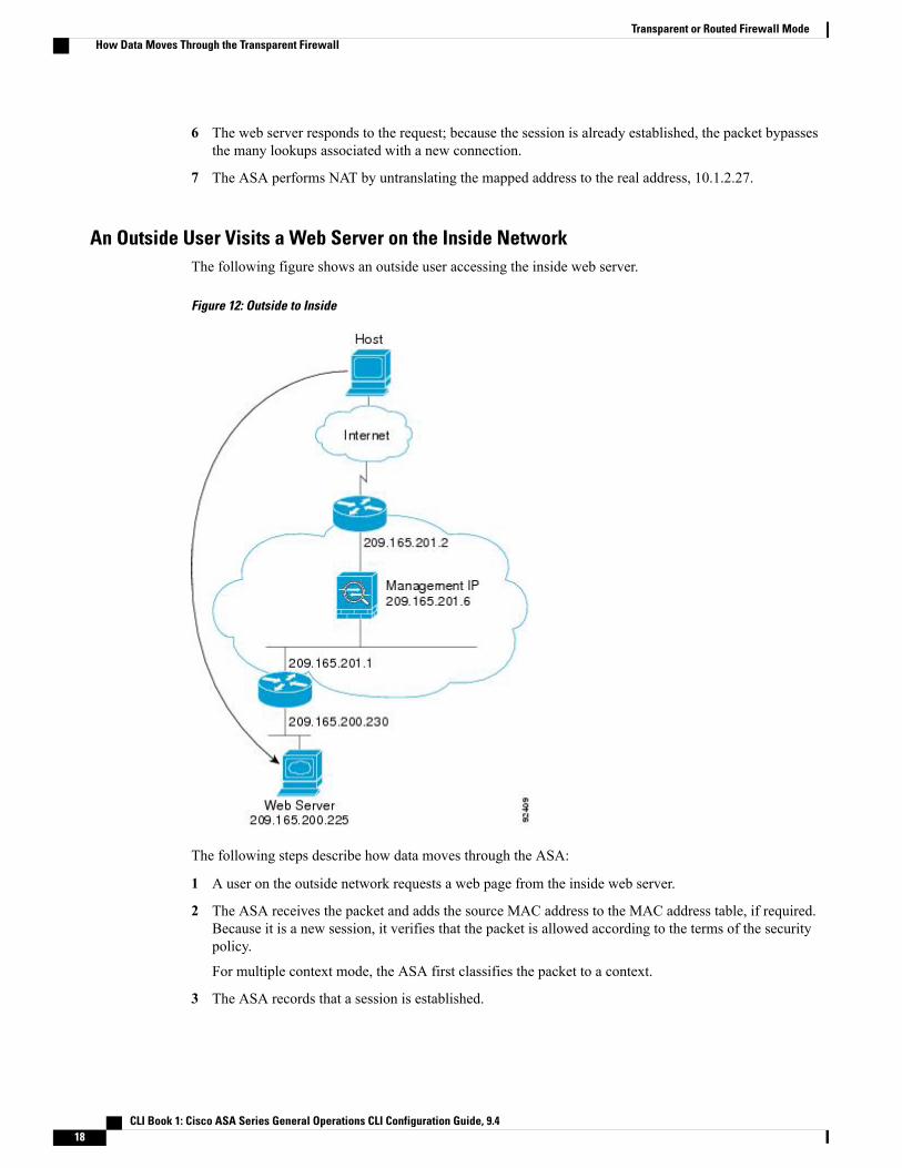
An Outside User Visits a Web Server on the Inside NetworkThe following figure shows an outside user accessing the inside web server.
Figure 12: Outside to Inside
The following steps describe how data moves through the ASA:
1 A user on the outside network requests a web page from the inside web server.
2 The ASA receives the packet and adds the source MAC address to the MAC address table, if required.Because it is a new session, it verifies that the packet is allowed according to the terms of the securitypolicy.
For multiple context mode, the ASA first classifies the packet to a context.
3 The ASA records that a session is established.
CLI Book 1: Cisco ASA Series General Operations CLI Configuration Guide, 9.418
Transparent or Routed Firewall ModeHow Data Moves Through the Transparent Firewall
4 If the destination MAC address is in its table, the ASA forwards the packet out of the inside interface. Thedestination MAC address is that of the downstream router, 209.165.201.1.
If the destination MAC address is not in the ASA table, then it attempts to discover the MAC address bysending an ARP request and a ping. The first packet is dropped.
5 The web server responds to the request; because the session is already established, the packet bypassesthe many lookups associated with a new connection.
6 The ASA forwards the packet to the outside user.
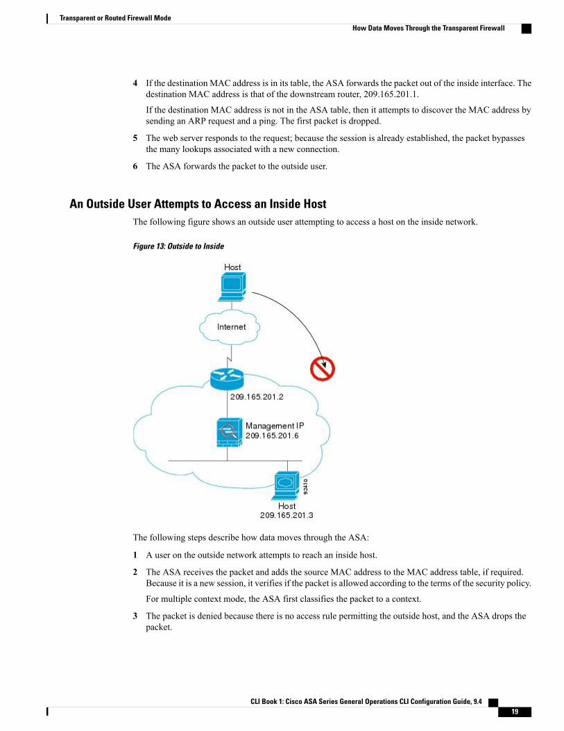
An Outside User Attempts to Access an Inside HostThe following figure shows an outside user attempting to access a host on the inside network.
Figure 13: Outside to Inside
The following steps describe how data moves through the ASA:
1 A user on the outside network attempts to reach an inside host.
2 The ASA receives the packet and adds the source MAC address to the MAC address table, if required.Because it is a new session, it verifies if the packet is allowed according to the terms of the security policy.
For multiple context mode, the ASA first classifies the packet to a context.
3 The packet is denied because there is no access rule permitting the outside host, and the ASA drops thepacket.
CLI Book 1: Cisco ASA Series General Operations CLI Configuration Guide, 9.4 19
Transparent or Routed Firewall ModeHow Data Moves Through the Transparent Firewall
4 If the outside user is attempting to attack the inside network, the ASA employs many technologies todetermine if a packet is valid for an already established session.
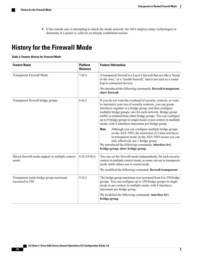
History for the Firewall ModeTable 2: Feature History for Firewall Mode
Feature InformationPlatformReleases
Feature Name
A transparent firewall is a Layer 2 firewall that acts like a “bumpin the wire,” or a “stealth firewall,” and is not seen as a routerhop to connected devices.
We introduced the following commands: firewall transparent,show firewall.
7.0(1)Transparent Firewall Mode
If you do not want the overhead of security contexts, or wantto maximize your use of security contexts, you can groupinterfaces together in a bridge group, and then configuremultiple bridge groups, one for each network. Bridge grouptraffic is isolated from other bridge groups. You can configureup to 8 bridge groups in single mode or per context in multiplemode, with 4 interfaces maximum per bridge group.
Although you can configure multiple bridge groupson the ASA 5505, the restriction of 2 data interfacesin transparent mode on the ASA 5505 means you canonly effectively use 1 bridge group.
Note
We introduced the following commands: interface bvi,bridge-group, show bridge-group.
8.4(1)Transparent firewall bridge groups
You can set the firewall mode independently for each securitycontext in multiple context mode, so some can run in transparentmode while others run in routed mode.
We modified the following command: firewall transparent.
8.5(1)/9.0(1)Mixed firewall mode support in multiple contextmode
The bridge groupmaximumwas increased from 8 to 250 bridgegroups. You can configure up to 250 bridge groups in singlemode or per context in multiple mode, with 4 interfacesmaximum per bridge group.
We modified the following commands: interface bvi,bridge-group.
9.3(1)Transparent mode bridge group maximumincreased to 250
CLI Book 1: Cisco ASA Series General Operations CLI Configuration Guide, 9.420
Transparent or Routed Firewall ModeHistory for the Firewall Mode