roto-verter energy saving applications - rex research · roto-verter energy saving applications...
TRANSCRIPT

Roto-Verter energy saving applications
Index Background………………………………………………………………………… Introduction ………………………………………………………………………. Technical explanation of operation in RV mode …………………………………. Overview of instant energy saving applications………………………………….. Guidelines to run motors in RV mode…………………………………………… RV test of energy efficiency vs. energy waste…………………………………… Recommended RV applications……………………………................................ RV’s reverse dynameter applications…………………………………………….. Lubrication testing and baring testing for energy saving standards……………… RV Sugar Cain mill……………………………………………………………… RV Impeller design………………………………………………………………. Theory examples of a RV power plant……………………………………………. Declination plant with RV run Tesla pumps………………………………………. Norms big motor RV tests ………………………………………………………… RV working in real devices………………………………………………………. Simple RV battery charging……………………………………………………… Clarification of engineering principles………………………………………......... Weight issue………………………………………………………………………. Essence of the RV running minimal current on idle…………………………….... Tests for Basic hard postulates…………………………………………………… Accurate debunking via test equipment by earl…………………………………… Recommended testing equipment for RV energy savings Tests………………….. Phils DC to AC start with the BCSRC RV………………………………………. The 3 Phase finally unlocked by Phillip Wood …………………………………. Anomaly readings from coupling the RV based on Hectors teachings…………… Recommended RV motor parameters………………………………………………

Efficiency-a : efficient operation b (1) : effective operation as measured by a comparison of production with cost (as in energy, time, and money) (2) : the ratio of the useful energy delivered by a dynamic system to the energy supplied to it. This document will present lab tested results which verify the capacity the Roto Verter effect has for energy saving applications. No where in the world TODAY are there better efficient energy savings methods in electric .8 - 1.25+ HP motors in comparison to the RV. The authors, engineers and inventor are not for profit. For the experimenter wishing to replicate the RV please consult the RE-OU PDF file and or RV laymen’s theory available from the file sections in these yahoo energy groups on the web.
[email protected] [email protected]
Quote- In engineering OU (Over unity) the fundertmentals must be enabled by an energy saving medium. What matters is quantification and method, the RV is primary an R&D tool which aims to educate the simple fact that the first energy you save is the one you don’t waste. If you save it then you can transform it, and it is only in these conditions that it is logically permissible to assume OU can come into play, fundamentally OU must start from energy saving applications.- Hector inventor of the Roto-Verter

Note: all enquiries and R and D questions are to be addressed formally by Hector on the EVGRAY and RVreplication yahoo energy groups, if he can not be reached contact Ashtweth and He will do to the best of his ability to aid:
[email protected] Some back round on Hector the inventor of the RV and TV (Trans-verter).Out of ANY R&D Investigator or inventor apart from Tesla, Hector is the first to TEACH how to operate a device from Standard Off shelve parts from a basic set of instructions. Hector is also the FIRST one to directly relate RADIANT ENERGY with RF (radio frequency) in the operation of the RV alternator, and teaches a way to produce this radiant energy the same as EV gray did in an LRC circuit under resonance. Please consult the RE-OU compilation mentioned for more detail on this. Hector has stated that he is willing to cooperate with University and Industry but will not be manipulated to let them Headhunt and shrink & dry brains hi and dry. Hector like Doug Konzen of the EVGRAY internet yahoo energy discussion groups are open sourced and discloses DIY R and D FREE for public knowledge.
Back round RV has been originally released open sourced from Hector Perez Torres R&D on alternate Energy Replicated by EVGRAY and RVeplication yahoo energy Group Members. The dates the RV was first disclosed along with the improvements span from as early as 1969-1980-1984-1999 to currently 2007. There are currently hundreds of engineers who have done replications and who deserve to be included as part of the history. Their theories, findings and personal contributions to the RV have enabled the progress to continue. Please consult the RV Peswiki page and yahoo groups mentioned for further credits. The engineers mentioned along with the not for Profit organisation Panacea-bocaf wish to state that the ever growing public input to the technology has enabled development of critically needed energy saving applications. You will find a detailed list and construction details of these energy saving applications in this compilation. The RV roto Verter method is Statutory Public copyright (Other Rights Apply) under a local and international. (Publication) Scientific discovery, the Roto conversion effect is covered by the publication statutory copyrights for 75 years. Further more upon the publication of the RV, up to 20,000 patents had Expired which may be technically paralleled or resemble the RV in any way. These include add a phase patents. In fact CAREY, Otto smith, and latest MEG & Bedini patents fall within material published under the RV’s related resonance & radiant energy issues. It should further be noted that when comparing Otto smith’s

patent to the method and operation of the RV, Otto smith works on a LOW impedance method as a VARIANT of magnetically current controlled add a phase concepts, and NOT the same as in operation of the RV. The RV is configured for freq matched HI impedance power on demand (energy saving) mode. Smiths patent also describes a freewheeling effect with a mistaken explanation. In the RV the Speed is a fixed synchronous or reverse induction function, and incrementally accelerated, not "free wheeling”. Smith’s device can be evaluated here. The TV (a concept called the trans-verter also designed by Hector) & RV are a METHOD and discovery and are covered by the PUBLICATION statutory copyrights for 75 years. A public warning is therefore expressed to any corporate or spurious group (same thing) intending on using ANY of the public’s knowledge disclosed in the RV, TV or Doug Konzen disclosures from the EVGRAY yahoo internet group to subjugate others for money, when you LOOSE you run with expenses plus damages. Hector has done 5 years of PATENT R&D so it’s advised that you sell your house now. Further to those attempting to Hijack public open source disclosures and make it "proprietary". The impedance and tuning & recovery disclosed in RV mode, including the theories and definition of over unity comprising Pulse length and intensity to saturate a core to Extract OU CEMF is public knowledge and pre dates the current patent imitations. This can even be traced to Time Pulsed 3 phase Inverter and pulsing circuits have been public since 1960. The RV is public knowledge and pre dates since the 80’s. The RV’s method as the RV’s diode plug recovery circuit and all its related work are covered by copyright and statutory copyright as published R&D free domain research. Weapon is PUBLICATION -Hector Quote: After the basics are applied using the method of the RV we can go into higher level, using the RV as an ENERGY saver can’t be denied, it’s very hard to suppress as it can be constructed from OFF the shelve parts. The RV energy saver can also enable potential for an OU generator. After applying the fundamentals of the energy saving RV method and operation, by default looping and OU will be made by anyone, mean time the education of the RV has to GO first as Energy saver. You can’t have Over Unity in a system of WASTE, you need first to MANAGE power by minimal losses, managing power by the RV’s HI efficiency will permit you to manage and transform an energy system towards OVER UNITY.. – Hector, edited by Ashtweth
Introduction

A motor is a device which uses electrical energy to produce motion. One phase and three phase motors are used in many residential and industrial commercial utility applications, examples can be found in pumps or fans, winders, conveyers, mixers, lathes, drills, saws, pumps and grain grinders. Most induction motors are wired operate with both starts and run capacitors for add a phase or power factor correction. A typical example is this 1HP electric motor which is usually applied in the role of a PUMP, GENERATOR, LATHE, SAW or AIR COMPRESSOR.
ALUMINIUM FRAME ASYNCHRONOUS -INDUCTION MOTOR

The separate run and start capacitors are housed in the box on the top of the motor. The specifications of this motor are: 240 volt \ 4.78 amp \ 1400 RPM \ 1HP -0.75kw \ 750WATT \ 13kg. Here is another example of induction motors with start and run capacitors used in a SAW, DRILL and BRICK CUTTER role.
Brick cutter
BAND SAW, the run and start capacitors are housed left on the side of the motor.
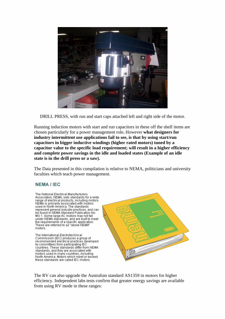
DRILL PRESS, with run and start caps attached left and right side of the motor. Running induction motors with start and run capacitors in these off the shelf items are chosen particularly for a power management role. However what designers for industry intermittent use applications fail to see, is that by using start/run capacitors in bigger inductive windings (higher rated motors) tuned by a capacitor value to the specific load requirement; will result in a higher efficiency and complete power savings in the idle and loaded states (Example of an idle state is in the drill press or a saw). The Data presented in this compilation is relative to NEMA, politicians and university faculties which teach power management.
The RV can also upgrade the Australian standard AS1359 in motors for higher efficiency. Independent labs tests confirm that greater energy savings are available from using RV mode in these ranges:

-60 hertz / 3 phase / 3 -7 HP motors give a higher eff .5 to 1.8 HP in RV mode. -50 hertz / 5-10 HP / 3 phase motors give a higher eff .8 - 1.13 in RV mode. This data is premise to mandate laws for no further energy wastage in variable load applications. RV Drill, lathes, punchers, rotary presses, planners, saws , cutters ,air compressors, vacuums & others can be optimized to lowest more effective power usage. Manufacture and industrial use are the turf were RV can excel in power savings using RV Drill, lathes, punchers, rotary presses, planners , saws , cutters ,air compressors, vacuums & others optimized to lowest more effective power usage. The First free energy the world gets is the one that does not go to waste. In solar it means using much less power cells more effectively ,for this means cost effective usage in 3rd world nations, water well pumps, grain grinders , & general machine use applications. Free solar energy for poorer nations can compete with greater economic Power more effectively used. Running motors in RV mode is a superior energy saving incentive that’s not currently utilized in mainstream industry applications or taught at the faculty level. The public must also help to enforce this energy saving standard to help save them money and their planet. Currently petitions to support the inventor and the ‘no energy wastage standards’ can be Signed at http://www.panacea-bocaf.org
Technical explanation of operation in RV mode Running three phase motors in RV mode is a method to operate a motor at HI impedances to its input. In RV mode the three phase motor is wired to operate on ¼ of the rated voltage from single phase power and uses the addition of start and run capacitors to generate the third phase. After the motor acquires rotation the start capacitor is switched off, the run capacitors value is then tuned to the lowest draw to match the load requirements.

60 hertz RV schematic
In the prime mover the windings are connected in series (to 480V mode), but driving the motor only from 110V grid (operating at ¼ of the voltage) this series-connection further helps to reduce input current. The HI impedance and 3rd phase generation create a transformer alike operation were 1/10 power usage can be attained at no load.
Running 3 PH motors from 1PH power via start and run capacitors is nothing new, however RV-mode is not like the common “add-a-phase” setup, but more related to impedance matching by tuning the voltage, frequency and pulse-width in advanced configurations. The RV principle is based on “matching the source to the needs of the load” [as referenced by Nicola Tesla] by tunning capacitors values to the load requirements. Resonance within the RV prime mover is responsible for the high impedance of the motor, seen from the grid/source. Under load inner resonance becomes broad banded, but is still there! The more it goes broadband, the more RV inner voltage drops (seen from the grid), and this results in higher input currents. This is what makes RV prime mover to a Power-On-Demand-Motor. This results in a yet unrecognised superior power management with many other advantages. When the motor is unloaded, the RV functions the same as a true transformer does. The primary winding (stator) is connected to the power source and the shorted secondary (rotor) carries the induced secondary current. Torque is produced by the action of the rotor (secondary) currents on the rotary repulsion from the off phase 3 ph fields and capacitor vectored virtual 3rd phase. Rotors typically consist of a laminated, cylindrical iron core with slots for receiving the conductors. The most common type of rotor has cast-aluminium conductors and short-circuiting end rings. This "squirrel cage" rotates when the moving magnetic
field induces a current in the shorted conductors. The speed at which the magnetic field rotates is the synchronous speed of the motor and is determined by the number of poles in the stator and the frequency of the power supply: ns = 120f/p, where ns = synchronous speed, f = frequency and p = the number of poles. When running, the rotor always rotates slower than the magnetic field. The rotor speed is just slow enough to cause the proper amount of rotor current to flow, so that the resulting torque is sufficient to overcome windage and friction losses, and drive the load. The speed difference between the rotor and magnetic field is called the slip and is normally referred to as a percentage of synchronous speed: s = 100 (ns - na)/ns, where s = slip, ns = synchronous speed, and na = actual speed. An electrical transformer uses minimal energy in its primary winding when unloaded. The RV functions the same by using minimal energy at its input when its MECHANICAL (shaft) output is unloaded. As RV starts, it is resonant; as it attains rotation its impedance becomes receding (running away from source); as you load it tends to go back to semi resonant state, where the extra phase takes the power factor lag as a leading angle in the extra phase, balancing the input to a PF ‘unity’. As such the power is more efficiently used than in standard all the time energy wasting motor. This RV LOW waste design has a capacity of 94+% efficiency on LOW power motors, and 90% energy savings on basic idling used in tools and intermittent or variable loads. The rotor in the RV becomes a reverse induction VARIABLE element that determines the IMPEDANCE relative to the input frequency and amplitude. So here we take MECHANICAL LOAD as a variable, reflecting a CHANGE in impedance rather than a PURE resistance to energy flow. In doing so, we reduce the thermal loss and increase power gain efficiency within the system. That means the ROTATING element of squirrel cage rides the AC wave, becoming synchronous to it, resulting in a very broadband impedance match to line, reducing losses as if it were a TRUE induction transformer; the energy transformation results in a rotary mechanical movement which reflects minimal loss to the source. The Roto Verter stator windings are wired in Y configuration and are having 3 terminals. We are feeding 2 of these directly with some sinusoidal voltage, which creates some current in 2 of the stator coils (they are connected in series in case of Y-connection). This current in these coils will lag the applied voltage by 90 degrees due to the inductive nature of these windings. The third terminal is fed through a capacitor. This compensates the lagging of current (current which is going through a capacitor will be leading the applied voltage for 90 degrees) in the third stator coil. Hence then there will a rotating magnetic field created in the stator windings, which will induce the current in initially static squirrel cage rotor windings.
The squirrel cage can actually be considered as a transformer secondary winding, which is in "shorted" state when the rotor is just starting its rotation. And what happens when you short a transformer? Its primary virtual inductance (and thus the total impedance) decreases very much and lot of current will be needed from the power source. Point is that to maintain this rotating magnetic field in the stator when the rotor is just accelerating, we have to supply a lot of current to ALL of the stator windings. That's why we need much bigger capacity for the start cap - Xc=1/(2*PI*f*C) - we are having constant frequency and in order to pass more current to the third coil also we need to decrease the reactive resistance of the capacitor, thus we need to increase the capacitor's value. So we will use the start cap that is able to pass almost similar amount of current to the third stator coil also. When the rotor comes up to speed, the rotating magnetic field of the stator will cut less and less. the squirrel-cage windings and the virtual transformer shorting effect decreases and thus the needed current from the power source also decreases. Now when we still have the big start cap in place, then it's Xc (reactive capacitance) will be so small when compared with the third stator winding's XL (reactive inductance XL=2*PI*f*L), that the total current in the third winding will be mostly determined by this XL value and thus the current in first two stator coils and third stator coil will be almost in the same phase, thus killing the rotating magnetic field that should be produced by the stator for normal operation for this kind of motor. Now we need to disconnect the start cap and keep only the much smaller run cap, which will restore the properly rotating field in the stator (the cap creates the needed phase shift for current in the third winding). This advice is valid only for the prime mover in UNLOADED CASE (for the case when we do not need to run big loads with it). The values of the capacitors and components are specific to the motor size used. The starting cap in the 60 hertz example is 100 to 200uF, the running cap is from 7 to 40uF (370V oil caps). Starting cap is to give a boost from 0. Big motors require it to acquire torque to move the rotor mass plus alternator mass to rotational RV effect speed. The run capacitor is chosen as to maintain best 120 degree rotation within the 3PH windings under the intended target load. This is the most efficient Power On demand process; Normal electric motor engineering design has an inferior inefficient power management process. The RV solves this design flaw and also makes solar cogeneration of motor applications possible where previously it would have been impractical. The benefit of running motors in RV mode will result in superior energy savings when used in the role of industrial machinery, intermittently in rotary punch applications. All applications which employ a lathe, a drill a grinder a rotary saw, a reciprocating pump, and also vacuum pumps run in RV mode can save energy, but this is only the beginning.

In the beginning the horse power of the motor in RV mode is re rated in the following ranges: In 60 hertz 3 phase motors from 3 -7 HP motors will give .5 to 1.8 HP in RV mode In 50 hertz 5-10 horse power 3 phase motors can be used, and will give about .8 - 1.13 in RV mode. The RV’s higher efficient re rated horse power is not a fixed value; the motor becomes more efficient in the loaded and unloaded states. RV mode can still reach the HP rating of the motor via boasting the voltage or frequency. This will give the process higher torque and still preserve the efficiency ratio. Examples of how to do this can be found in this compilations example of using frequency drives with the RV. It is possible to run 1 PH motors in RV mode however in single phase configuration it requires 200mF 370 VAC caps (as an average to go into resonance) at 12 Ohms impedance, but will have a low Q which varies a lot, and needs further lab experimentation. A single phase demands more to run in RV mode as is lower impedance than a normal 3PH motor. You can wire one phase motors to 460 VAC and can run them in RV mode vectoring the START phase at the proper angle (45deg). It will however be a bit less effective than a 90DEG 3PH force vector but it will be effective, all 1 PH motors can be run RV mode this way.
Over view of the RV’s energy saving applications. In RV solar co-generation applications the difference compared to normal motors used in an identical role from inverters is estimated to be 10 solar cells less you need to run your Solar shop lathe, drill, grinder, rotary saw, reciprocating pump, and or vacuum pump. Example: Using a 3PH motor wired to run in RV mode unloaded will result in a draw of approx 40W from 3.5 amperes max, with a 90% eff inverter. A normal 1 HP motor unloaded normally draws about 890W IN THE SAME ROLE, which would run down a battery by using a constant 77.9 AMPERES at 12.7 VDC. A Normal 1 HP conventional motor uses a CONSTANT 880W to run with no load, when loaded all are at about 79%- 88% efficient. Using the same application from a motor configured to run in RV mode will uses as little as 40-50W idling with no load and is at 94%+ eff when tuned to the load requirements.

A 5 HP Baldors motor modified to run in RV mode to give
.8- 1.13 HP for energy saving applications. The above 5HP Baldors motor specifications are: 1450 RPM /50 hertz /4kW / (line power) is at 88% eff at 746W/HP (conventional) = 4.7 HP (at the shaft). In RV mode this motor can deliver about .8 - 1.13 HP and can reach a 94%+ efficiency. This motor was tested with no load and compared to this typical one phase 240 volt \ 4.78 amp \ 1400 RPM \ 1HP -0.75kw \ 750WATT \ motor.
The RV idled on .7 amps AC at 240 volts = 168 watts And is estimated to be 94%+ efficient when loaded at 1HP The non RV idles on 1.84 amps at 240 volts and when loaded is 4.78 amps at 240 volt s=1147 watts

By a typical estimation of 60 hertz lab figures we can conclude: A 1 HP RV uses 40W< idling and 794 W when loaded (1HP) 94% eff constant A 1 HP (non RV) uses 888W>idling and 940W loaded (1HP) 79% eff constant Equalling- 848W wastage for normal motors compared to operating 3PH motors in RV mode. As you can conceive, this gives premise for running motors in RV mode and demonstrates the fact that basic induction motor design can be enhanced using Hi impedance and capacitor phase generation vectoring (resonance). Running motors in RV mode particularly solves problems which lie in solar run mechanical energy conversions. The RV creates power loss reduction which allows the battery to charge. This completely permits the operation of other wise wasteful power implements with cogeneration of the solar industry. No other method is possible to make low power asynchronous solar cogeneration possible and practical In Solar energy applications you can tune the RV motor to operate as a power on demand device, the RV will use from 12-50W and enable the motor to deliver up to 1.8 HP with an effective efficiency of + 94%. This figure is estimated to have a 90% minimal energy savings capacity on the motors idling time, and can operate machine tools, lawn mowers, Pumps ,saws , log splitters , drills, lathe ( Solar Home workshop ). This currently is Impossible with “standard” electric motor setups.
Guidelines to run motors in RV mode The configuration varies from motor to motor that will be used. Here are some general guidelines: 1) the RV power output is about 1/4 to 1/5 of the rated one on the motor plate. So check what power you need (in kW or HP) and then take a 3PH motor 4-5 times 'stronger'.(people will now say that they are fooled because you need a 5x bigger motor. The fact is in RV mode, the motor is much more efficient versus standard use, and also at idle consumes very little -energy savings!) 2) If you want to run it straight from the mains, then you need to select a motor with a voltage rating of about 2x that per winding (or 4x in WYE connected). Example: if you have 110V 60Hz mains, take a 230/460V dual winding 60Hz motor; connect windings in series and in WYE. (460/4 = 115 = is close to mains) Example2: if you have 230V 50Hz mains, take a 400/690V 50Hz motor, and connect in WYE (800/4 = 200 = fairly close to mains - better is 220V) Alternatively, if you feed the motor from an inverter, then modify the inverter to set the correct voltage output for your RV motor (is relatively easy to do within a certain range). 3) In terms of speed, check the desired speed of your tool. If you can find a motor that is close to that speed, use that one.
The standard motor speeds are:
for 50Hz: 3000, 1500, 1000, 750 rpm (=2-4-6-8 poles)

for 60Hz: 3600, 1800, 1200, 900 rpm (in fact about 3-5% less than that because of slip)
The speeds of 3000/36000 and 1500/1800 are most common. If you do not have a good match, you can use a reduction gear or pulley (but those have energy loss), you can also modify your inverter to alter the frequency, then no pulleys or gears are needed. For more information on the RV’s frequency adjustable method please consult the index. For the 60 hertz RV, it is optimal 1:4, i.e 120:480, 230:920 (grid 230VAC and motor wired to 920VAC). The latter requires rewinding the motor, but the positive side is that you need lower run capacitors as the inductance is much higher. Note it is possible to build an advanced binary capacitor that is switched by CPU that senses the input current and auto-adjust capacitors for full Range load. Running motors from 230VAC wired to 400VAC is also quite practical in terms of energy savings, something interesting happens when you decrease the input voltage, while maintaining the torque and optimal run capacitor. The Amperage remains roughly the same (all depending on circumstances), and you wonder where the energy was lost in higher voltage drive mode. It is assumed the PF=1 on both HV (230VAC) and LV (120VAC), so we may have a 50W difference (this report was based on a real life example). Where did the energy go - heat? No, the current was only 0.5A that does not explain heat losses. The possible explanation is that energy has gained in high impedance mode (120VAC). You may use two 400VAC+ rated motors in series (WYE) on the same rotor and drive them from 230VAC to have 1:4 proportion. Or increase the freq 2x ->100hz to have RV mode. When motor is wired to 460VAC (50hz), by increasing the freq 2x, it is virtually wired to 920VAC (100hz). So you need a 230VAC freq tuneable inverter. That is the whole idea to have the voltage and freq increased proportionally to have very powerful RV's. You can use low RPM motors (980RPM) and rotate those at 1960RPM 120VAC motors can run in RV mode with 28VAC. It just requires x4 to x6 capacitance using oil run caps. Start caps can be lytic (to lower price cost). That means in 24 VOLT DC battery systems you can run a 120VAC motor DIRECTLY FROM THE BATTERY DRIVING IT with a IGTBs BIASED H network and thus lowering the cost of an integrated inverter system. The motor can also be run directly from DC as DC becoming a brushless RV motor direct motor driver. Andrew, You must be aware that an electric motor will draw up to 7 times the motor's full load current on start up, even though this may be only for a fraction of a second. Your inverter must be able to handle this inrush current. A modified sine wave 3000 watt inverter will handle up to 8000W (Peak) inrush current which is approx 32 amps. Divide 32 amps by 7 (the amount an electric motor will need for start up) = 4.57 amps. This tells us that the inverter will start an electric motor which has 4.5 amps full

load current or less - if you exceed this the inverter may start larger motors if they are unloaded but we cannot be guaranteed t do so.
RV test of energy efficiency vs. energy waste To allow a proper measurement accuracy and calculation of real power distribution, the motor used in the tests against the RV was power factor corrected with capacitors to match the PF of the RV. This logical for many reasons, as power companies want better power factor in energy operation as industrial people will recognize. Power factor explains the true power and apparent power being consumed.
Power Factor Correction Makes Every Watt Count! For some reason, a lot of engineers and technicians seem to have a problem with understanding power factor correction. However, not understanding what a power factor is and how to correct it can lead to overcharges on your electric bill. An incorrect power factor is like driving a poorly tuned vehicle... the car moves, but you pay for a lot of extra gas! As your local utility distributes electricity over the grid, line losses occur, in other words, the voltage lags the current and the actual power available is not as great as electrical meters based on wattage claim. Early efforts to correct this phase difference were centred on the fuse box. However, as power factor correction became popular with major companies, the utilities changed their meters from watt measurements to read the current consumption thus causing an actual increase in utility bills where the power factor was corrected at the fuse box. This has forced power correction efforts to be decentralized and to be performed on individual motors. You must properly read a KVAR meter to measure how much your voltage is lagging your current. Baldors motors mention this very task of power factor correction in motors. Here is a direct exert from their energy efficiency document
In Power Factor Correction the apparent power in an AC circuit has been described as the power the source "sees". As far as the source is concerned the apparent power is the power that must be provided to the circuit. You also know that the true power is the power actually used in the circuit.

The difference between apparent power and true power is wasted because, in reality, only true power is consumed. The ideal situation would be for apparent power and true power to be equal. If this were the case the power factor would be 1 (unity) or 100 percent.
There are 3 ways in which this condition can exist:
(1) If the circuit is purely resistive or (2) If the circuit "appears" purely resistive to the source.
(3) The X and L cancel each other out To make the circuit appear purely resistive there must be no reactance. So the current will not lag the voltage. Power factor correcting motors will optimise the measuring performance and show where the real power is being used or wasted. Also to present the benefits involved in power factor correction of motors the tests will involve a kilowatt-hour meter and a power factor meter to show the energy saving figures. A motor with .1 power factor can only do 10% of the load of a PF1 motor. The PF .1 motor will not function if it tries to drive the same load as a fully-loaded PF of 1 motor. The justification for this can been seen in the meter readings of the power factor corrected motor tests verses the RV. After a sample motor rated at 2HP was power factor corrected so that it was close to the power factor of the RV motor. The difference on the meters showed The RV costs $12.00 per month with the load, where the non-RV motor costs $55.00 per month with the same load. With the power factor correction the non-RV motor, takes $26 per month to run. Without the PF correction, the non-RV motor won't even drive the load correctly and still costs $20 per month to run. These poor power factor issues need to be addressed; and is where normal motors waste energy as opposed to where the RV saves it. These Test results were confirmed by an open sourced engineer Matt whilst evaluating the Roto Verter comparing a 1.8 HP RV motor against a 2HP non RV motor (PF corrected) To PF correct the motor different size caps were attached across the incoming power. The caps are attached with one lead to the common and one lead to the hot wire. The motor ended up with a 115MF cap. Then the experimenter checked PF was with a PF meter Link To test your RV motor with equal watt HRS meters used in the utility line. Measure the device under load test only. RUN the 2 idling under the meter reading and read the effects on the line from a CONSTANT source. The power FACTOR itself can become trap if the power factor is negatively affecting In INPUT; this effect will increases the current logarithmically, then there is a loss increase. But in the RV such a loss does not represents the LINE loss and the 3rd phase reading exceeds the input any way you put it.

Phasing at 120Deg creates a PF of 1 in the source; the ABC phases are higher efficiency in average to input, whatever the Meters say go by the Scope reading and the BOOK formulas to define this truth. In fact the RV’s application in power saving is FACTUAL in a DC sourced battery and inverter shunt set up. Verification of this can be done by going full solar and making the utilities obsolete. In the input of a one phase RV the power factor is irrelevant in 3 a phase relation by being relative to each 3 phase’s interrelation, the angle of rotation is what matters and PF does not define that. But the CURRENT & voltage Phase does. This is in the same context of the book laws as in an LRC current where the PHASE is the constant VOLTAGE Phase and is the one that’s shifting in components. This is interesting and is the same as viewed from an RF antenna perspective. The components represent Voltage and Current nodes where the 0 points are present within these standing wave NODES. The RV creates a BROADBANDED semi resonant condition at idling so it has a LEADING VAR relation to line input and a semi NUL vectoring of PF RF signal in SERIES LC identical motor where acting as an ALTERNATOR of the 3rd phase. To avoid complications it is advised to design full solar applications for proof of principles comprising A DC battery with identical inverter fixtures with the exchangeable loads. (Eliminate voltage phase AC in accuracies) They must be identical applications & loads, the purpose is to confirm and demonstrate the RV is SUPERIOUR POWER MANAGEMENT. Further that the RV is justification to creating new standards (which needs to be mandated by law) in electric motor design for GREENER higher efficiency.
The RV solar battery and inverter method guide lines are: Equal rated batteries are obtained and connected with a hydrometer and tested to equal, and then match the two inverters RESISTIVE and Inductive reference loads, test and certify to equal. Tune the RV (via run capacitors values) to an equal mechanical load and see what motor wins. This will confirm the Basics hard postulates of the RV which show how the idling power savings saves the battery power needed to allow PRACTICAL solar cogeneration of electric motors. This Data is applicable to:
Industrial applications With the relevance of using the RV to operate intermittent use applications more efficient in industry.
Solar "off-the-grid" systems

With the relevance of being able to operate solar machine shops where previously it would have been impractical.
NEMA and universities With the relevance to the test data which qualifies to upgrade the required energy efficiency standards of .8 to 1.8 HP electric motor applications. This Data is also relative to NEMA, politicians and university faculties which teach power management.
The consumer With the relevance to a logical environmental responsibility, the money it will save them from the performance of the RV’s energy savings. The collaboration of the open sourced engineers working on the RV technology also provides opportunity for social reform. The RV being disclosed open sourced aids the public by serving their needs in a non regulated non profit environmental role. The public consolidating with open sourced engineers to produce open sourced energy technology into their daily applications is reform the public needs to quell spurious non environmental money subjugating energy technology from their lives and keep it obsolete permanently. Public grants for a non profit division to contract the already available open sourced engineers in a research and development centre can bring this genre of technology into public service. The non profit organisation panacea-bocaf has to begun essential organisation to consolidate this into reality and produce open sourced free energy in a granted centre for the public. By consumers using the RV It means end to global warming energy crisis with energy savings and efficiency boasting from:
Power on Demand Power factor correction
Power management This justification for running motors in RV mode is needed to be understood/ SOLD with the public’s motivation to apply the Roto Veter technology. The Energy saving readings demonstrates that there is need to address the WASTE issue, politically and scientifically. THE RV’S ENERGY SAVING FIGURES IS PREMISE for the public to lobby for energy efficiency standards to match the RV’s power management and Demand NO FURTHER ENERGY WASTAGE. You can sign petitions for no energy wastage to address this at Link
Recommended RV applications
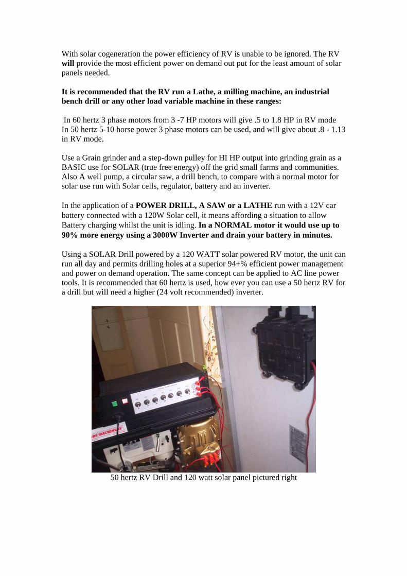
With solar cogeneration the power efficiency of RV is unable to be ignored. The RV will provide the most efficient power on demand out put for the least amount of solar panels needed. It is recommended that the RV run a Lathe, a milling machine, an industrial bench drill or any other load variable machine in these ranges: In 60 hertz 3 phase motors from 3 -7 HP motors will give .5 to 1.8 HP in RV mode In 50 hertz 5-10 horse power 3 phase motors can be used, and will give about .8 - 1.13 in RV mode. Use a Grain grinder and a step-down pulley for HI HP output into grinding grain as a BASIC use for SOLAR (true free energy) off the grid small farms and communities. Also A well pump, a circular saw, a drill bench, to compare with a normal motor for solar use run with Solar cells, regulator, battery and an inverter. In the application of a POWER DRILL, A SAW or a LATHE run with a 12V car battery connected with a 120W Solar cell, it means affording a situation to allow Battery charging whilst the unit is idling. In a NORMAL motor it would use up to 90% more energy using a 3000W Inverter and drain your battery in minutes. Using a SOLAR Drill powered by a 120 WATT solar powered RV motor, the unit can run all day and permits drilling holes at a superior 94+% efficient power management and power on demand operation. The same concept can be applied to AC line power tools. It is recommended that 60 hertz is used, how ever you can use a 50 hertz RV for a drill but will need a higher (24 volt recommended) inverter.
50 hertz RV Drill and 120 watt solar panel pictured right

The above RV drill idled at 120 watts, and was compared to the following ¾ horse power drill rated to 5+ amps under full load.
Upon idle the above ¾ horse power motor drew 2.21 ACA.
2.21 AVCA draw consumption idling
Below is the RV drill subjected to the same load

RV drill drilling the same load
The RV drill idled on .5 ACA, and under the same load ranged from .6 ACA to 1.25 ACA! Also a demo can be given in 60CPS using 120VAC and put into justify the issue of needing a new engineering notion of UNIVERSAL devices which are tailored to work from 47 to 450CPS. This is another engineering step toward power savings and equipment weight reduction in a near future using the amplitude, frequency and pulse length management (frequency drives ). IF we compare the figures the nations using 60CPS they waste 20% more energy than those using 50CPS and they do it 20% faster If the 50CPS nations go to 60CPS in RV modes they will save 80% over the ones using 60cps in normal ways, (you can drill holes 20% faster!). Lets say you choose 5HP 1725 RPM, use a modified frequency drive to get it to say 6,000RPM (tolerable to motor )in RV amplitude-pulse length adjusted 3PH modes. You will then get approximate 7HP at down gearing to your planner, if adjusted to the lowest friction it will work on power on demand mode real nice. Using a normal RV and in 50CPS is marginal, and will not be as effective as 60CPS or in use with a Frequency drive but still will save quite a bunch in electric power. A 7.5 to 10 HP (marginal may do ) and finding the best tool harmonics speed to best cut the wood type you use will be needed .

60 hertz free wheeling RV
The above 7.5 HP 60 hertz motor was run in RV mode to give 1.8 horses power for power on demand applications. The motor run was run from an inverter and returned an idle draw of 5.5 DCA at 12VDC which equals 66 watts.
Inverter running the RV
In the machine tool trade there is a speed where tools and materials are worked in the best efficient way, having a frequency drive can give you the advantage to tune the tool to the best performance in a given wood density with the cutting tool best performance to cut it with the best finish possible. That is adapting a capability of NCC to tools using power management optimization. Manufacture and industrial use are the turf where the RV can excel in power savings using RV Drill, lathes, punchers, rotary presses, planners , saws , cutters ,air compressors, vacuums & others optimized to lowest more effective power usage. The First free energy the world gets is the one that does not go to waste. In solar it means using much less power cells more effectively ,for this means cost effective usage in 3rd world nations, water well pumps, grain grinders , & general machine use

applications. Free solar energy = poorer nations can compete with greater economic Power more effectively used. Here are harbour freight examples which are a perfect substitution and recommended by Hector to demonstrate the RV’s power on demand energy savings. Check at the end of this compilation for the guide for choosing the right rating RV motor. It is important to select the right application to suit the horse power range and allow the proper efficiency. Three speeds to cut everything from brass and aluminium to rugged alloy and tool steels! In horizontal position, use the gravity feed adjustment to increase or decrease cutting pressure. 6-3/4'' x 6-3/4'' table for use in vertical position. Blade and heavy duty stand included. Cutting Capacity: 4'' x 6'' (rectangle), 4'' (round) Blade size: 1/2'' x .025'' x 64-1/2'' Blade speeds: 80, 120, 200 FPM Bed width: 7-1/2'' Vise: 7-3/4'' x 6-1/4'' Overall length: 37'' Height: 38'' (horizontal); 54''
• (vertical)
Source http://www.harborfreight.com/
Replace the motor pictured above with a motor running in RV mode.
12 SPEED FLOOR PRODUCTION DRILL PRESS
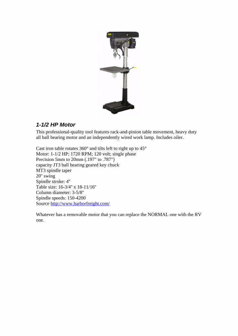
1-1/2 HP Motor This professional-quality tool features rack-and-pinion table movement, heavy duty all ball bearing motor and an independently wired work lamp. Includes oiler. Cast iron table rotates 360° and tilts left to right up to 45° Motor: 1-1/2 HP; 1720 RPM; 120 volt; single phase Precision 5mm to 20mm (.197" to .787") capacity JT3 ball bearing geared key chuck MT3 spindle taper 20'' swing Spindle stroke: 4'' Table size: 16-3/4'' x 18-11/16'' Column diameter: 3-5/8'' Spindle speeds: 150-4200 Source http://www.harborfreight.com/ Whatever has a removable motor that you can replace the NORMAL one with the RV one.

Example of a modified Floor Drill press with an RV motor
Other Examples with solar cogeneration or with line AC grid input. USE the RV to optimize a water pump impeller design by Ceramic low friction seals. This can be experimented in hydroponic FARMING in a role of SOLAR POWERED water recirculation. A belt woodcutting saw with an installed pulley to your RV tuned by the run capacitor to the lowest draw will be more efficient than the normal motor. This is the type of availability of PRACTICAL DO NOW RV applications. With a band saw it is not logical to draw 800W instead of only using 50W running in RV mode and 500 to 700 W on demand (Cutting big piece of wood). This application can be made even simpler with a current start switch to start RV automatically. The rest of Band saw is left as is.
Example of using a bench drill powered by the RV Try using the same drill bit size and drill 200 holes on a wood plank or metal piece, then compare the watt HRS used. This can be done with a 3PH motor wired to run in RV mode. The concept is to fit the motor and belt pulley. Guidelines for this are stated in the next section. The belt and pulley system can ALSO be improved on using low friction segmented flexible belts, all energy losses can be quantified and mitigated as the RV can function with REVERSE DYNAMOMETER CAPABILITY. (See index for explanation). Two separate bench drills are obtained; drill no 1 is to be a single PH (phase) 1 HP (horse power) rated motor; the other is to have an RV modified motor. The RV modified motors can range from:
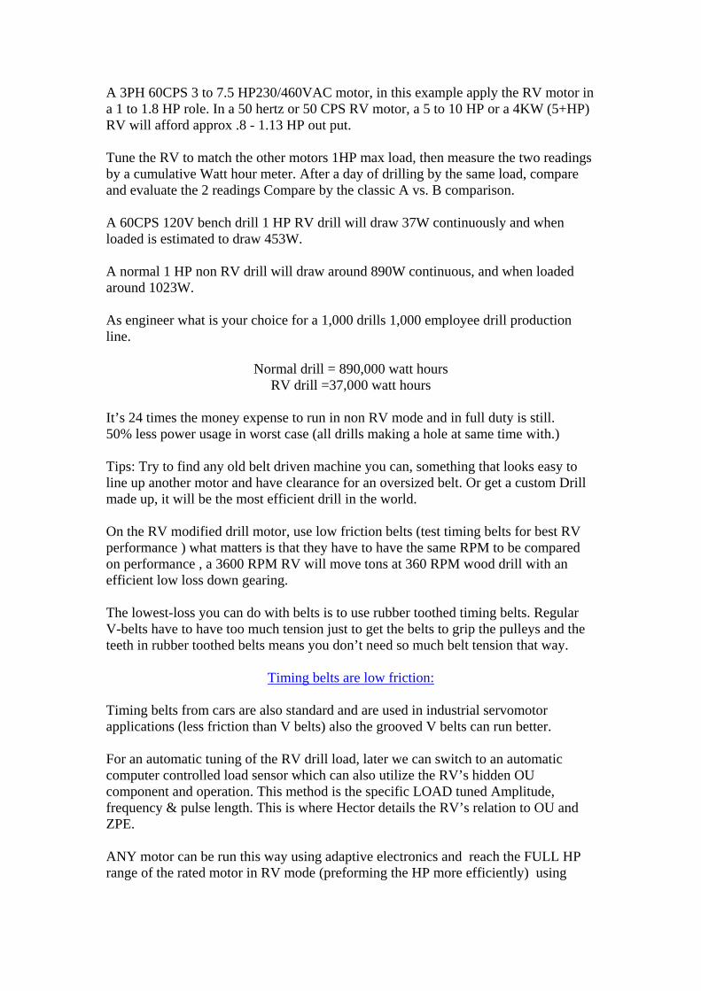
A 3PH 60CPS 3 to 7.5 HP230/460VAC motor, in this example apply the RV motor in a 1 to 1.8 HP role. In a 50 hertz or 50 CPS RV motor, a 5 to 10 HP or a 4KW (5+HP) RV will afford approx .8 - 1.13 HP out put. Tune the RV to match the other motors 1HP max load, then measure the two readings by a cumulative Watt hour meter. After a day of drilling by the same load, compare and evaluate the 2 readings Compare by the classic A vs. B comparison. A 60CPS 120V bench drill 1 HP RV drill will draw 37W continuously and when loaded is estimated to draw 453W. A normal 1 HP non RV drill will draw around 890W continuous, and when loaded around 1023W. As engineer what is your choice for a 1,000 drills 1,000 employee drill production line.
Normal drill = 890,000 watt hours RV drill =37,000 watt hours
It’s 24 times the money expense to run in non RV mode and in full duty is still. 50% less power usage in worst case (all drills making a hole at same time with.) Tips: Try to find any old belt driven machine you can, something that looks easy to line up another motor and have clearance for an oversized belt. Or get a custom Drill made up, it will be the most efficient drill in the world. On the RV modified drill motor, use low friction belts (test timing belts for best RV performance ) what matters is that they have to have the same RPM to be compared on performance , a 3600 RPM RV will move tons at 360 RPM wood drill with an efficient low loss down gearing. The lowest-loss you can do with belts is to use rubber toothed timing belts. Regular V-belts have to have too much tension just to get the belts to grip the pulleys and the teeth in rubber toothed belts means you don’t need so much belt tension that way.
Timing belts are low friction: Timing belts from cars are also standard and are used in industrial servomotor applications (less friction than V belts) also the grooved V belts can run better. For an automatic tuning of the RV drill load, later we can switch to an automatic computer controlled load sensor which can also utilize the RV’s hidden OU component and operation. This method is the specific LOAD tuned Amplitude, frequency & pulse length. This is where Hector details the RV’s relation to OU and ZPE. ANY motor can be run this way using adaptive electronics and reach the FULL HP range of the rated motor in RV mode (preforming the HP more efficiently) using

Amplitude control Voltage from 120VAC to 460VAC (Frequency adjusting or boasting the voltage). In the RV drill tests the GEARS for the optimal performance at the drill head against the normal drill, this gives the POWER to optimize & is professional RV use in R&D to quantify and improve power performance in the field. Machines can be optimized for their particular task, be it Punching or drilling a Hole, pumping liquid, moving objects or any quantifiable energy usage.
Guide lines for drill modifications If you are going to test: A 3PH 1HP motor versus 3PH 3HP+ motor in RV mode. Test setup is a drill bench where the motor can be changed without problems.
== 3PH tests == To demonstrate that normal motor may draw idle say 1.5A constantly (1.5A x 400VAC x 1.732 = 1039.2 VA x PF) with PF=?, thus we pay still for 1.5A normally unless we use special kVAR packet. The RV draws maybe below 50W. Motors must be the same RPM of course and RV must not have the FAN as it is not required - no heating problems. 1HP motor connected to 3PH we can use power factor correction (PFC) capacitors in WYE, say 10uF (just guessing), in the range from 5uF to 30uF and at the same time measuring how the amps go down. I know those amps will go down, when we optimize the PF near 1. Not good to go exactly 1 when doing PFC due to resonance as per book. When we have reduced the current consumption for normal 1HP motor, we can calculate its real power consumption in watts (now we know PF is near 1).
== 1PH tests == We can also test 1HP motor, being wound to 230VAC nominal and running it also at 230VAC with some 16-20uF cap as usually those single phase bench drill's are designed. This is also add-phase, but it is not RV mode, because of the wrong voltage level (too high and saturating). As those bench drills do some work even when unloaded due to belt friction, FAN is required. And compare it to RV motor.

RV Drill press with binary switched Capacitor bank above
The above 50 hertz RV motor used in this drill press from the 240 volt line input idled on about .5ACA at 240 volts to equal 120 watts. This RV method is an unstoppable means to make possible solar powered RVs which could also grind grain in remote villages, pump water in Africa, drive electric boats cars & planes without polluting water land or air, making Paradise on earth. Tips-Lets say you have 50 Hz 460VAC and 60 Hz 460VAC same HP motors? What is The difference? 60 Hz motor has 20% more wire length. Induction is higher 44% (1.2x1.2).Running 60 Hz motor (ordinary way) from 50hz 3PH grid, it will take more idle and running current.20% more or less wire, however, is not an obstacle for the RV mode I think. What I strongly suggest is that 60 Hz is better than 50 Hz in RV mode, since the resonance Q is better. For both prime mover and alternator.60hz alternator - self induction with capacitors will start much better. If you use 60hz or freq drive 60-100hz, it would be good for RV. Also note, if you increase freq 2x, increase the voltage 2x as well, retain the proportion, so RV mode goes on and the eff and power improves. Simple RV mode controls with frequency drives can be modified to use frequency control, amplitude control & pulse length control for even higher efficiency. Freq drives. Adding a DC amplitude level charge control and optical isolated IGBT gate within a range of say 50 to 480 VDC at the motor drive stage with minimal cost is an effective parameter and a specific range to improve applications. Computer Defined Parameter Universal AC motor drives.

The RV effect can be PULSE tailored within REACTIVE component itself being the source the capacitive element defined by varactor theory as a predetermined voltage (amplitude) and pulse length (time current raise vector) (.triggered pulse) Hector describes running a 1MEGAWATT RV motor using SCR, IGBT & transistor frequency drives.(You use the power needed at demand ...) WE ran I megawatt motor with RV system input of 3KW, tested full force 480VDC battery bank at 4000amperes surge. For the following example this 2 in one shop equipment module employs a lathe and drill which is powered by a 1HP motor, this all in one shop tool can be improved to not only operate as a solar work shop where previously it would be economically impractical, but can save energy and money in the line AC grid when power managed by the RV.
2 in one drill and lathe
RV grinder Credits got to Ron for this. Referring to this pic:

The gizmo on the right is a standard 8 inch bench grinder.
Left is the RV motor. Note the small size of the spindle that sticks out and thread for the nut to hold the wheel on. Also note the small step at the motor end where the collar (laying on the bench) fits up against. Now if you look at the 3 hp shaft, on the left, you can see it has none of these features as it’s to big and too short (that’s what all the girls say to uncle Ronney.) So that’s all the drawing presented, it’s a sleeve that slips over the motor shaft and has a spindle that sticks out on which to mount the grinding wheel. Imagine this hub slipped over the motor shaft. but having a shaft welded on, sticking out with a thread cut on it for the nut, two side collars to hold the grinding wheel, the nut tightened up, this would be a visual perspective of an RV grinder.

A Bench grinder 60 hertz 3PH 460VAC motor can also be made to run more efficient in RV mode. To be further made simple the speed and torque must match the ones required for original operation or better, a pulley down stepped 3450 RPM RV will definitely outperform any stock 1725 1/4 to .5 HP motor. A Basic example-1 HP RV is can be made from a 60 hertz 5 or 7.5 HP 3PH motor, the then max load is to be calculated and the RUN capacitor can be set in a mid adjustment range (broad banded), even though the run cap wont be optimally tuned to the specific loaded condition, the RV will outperform the normal motor!!! Baldor’s motor’s can also wind up 120,240,380,460 & up to 920VAC 3PH Motors which can be RV modified anywhere from 100-120 200 240 VAC 47 -60cps with only needing to be using capacitors and centrifugal start switch
RV current relay This is an example of a tuneable current relay put it inside a box. Can be used to start RV automatically - (RV lathe,). Similar to Circuit: using 5 turns as primary and 12V output as the secondary on toroid transformer.

Further examples can extend to a coffee bean grinder; a grain mill is to grind grain into flower (dust) and can run with RV with SOLAR energy. This means a lot of savings using power milling not spinning with a load, same as a bench drill lathe, band saw, fence post drill, and a lawnmower. The ultimate application and capacity the RV has to save energy lies in the construction of a superior solar shop module.
Centrifugal switches The following is an article written in machine design on the topic of centrifugal switches. The information for the article was provided by the Torq Corp. www.torq.com Design: Link Their centrifugals would work with the RV. All RVs can be started using these switches for EMP proof simple non computer driven Spartan made RVs. You don’t need a computer to drive a home drill fed from a hydro run generator power. Switch has to be specified if for 50 or 60 cycles & motor speed and cut off threshold.

The shaft measure & fit options also need to be considered, Hector prefers the ring type governor with hex screws not the hammer in type for in shaft installation. The switch can be fitted to fan cover in most motors using plastic spacers and drilling a few small holes, the governor if hole oversized can be adapted using PVC pipe spacers lathe turned to fit governor hole size and shaft size ... (pressure tight fit). on big motors a hole can be drilled & tapped in shaft centre and governor fitted with a governor centring spacer screwed in with a machine screw 1/4 24 or 3/8 24 For home made phase converters these switches are priceless! As they substitute all this cumbersome relays Otto smith & others use in their already obsolete patents. For hi loads switch can handle a HI power relay or solid state SCR ac module driver.
RV as a Reverse dynamometer
When applied in the application of an airplane propeller design, the RV can be installed with a prop pulling motor set up for a rail pulling weight measuring device. First you must hunt for the strongest pull and lowest drag electric power usage. Examples are in the Tesla pumps design. You must test the drag and pressure then optimize for the highest flow highest pressure - lowest power usage from the RV. Other applications are in Low Lenz law generator design, hunt for the highest output lowest input. Other uses are, testing Lubricants, transmission energy loss, and monitoring the drag increase in mechanical systems with current limit alarm. REVERSE DYNAMOMETER CAPABILITY= the ability to test how much power a rotating piece of machinery is actually USING. A Dynamometer is used to measure how much mechanical energy is being produced (transformed, actually) at the rotating shaft of a motor. Using logic and the context of Hectors posts, a Reverse dynamometer measures how much rotating mechanical energy is required to make something spin. Since the RV only has the losses from its bearings, an increased load will be reflected by a linear increase in the amps driving the RV. A normal AC motor changes power factor and efficiency depending on the load put on it so it is virtually useless for evaluating the power usage or efficiency of the driven object. One method is to take a low friction bearing and normal drag grease and compare it being spun by the RV & take readings ,a new set of TESTING standards can be made for bearing replacement and lubrication, resulting in PERFORMANCE and ENERGY savings in Shop Home or industry use. The RV can be applied as A NEW R&D tool and POWER SAVING device. This energy saving RV method may be verified also by using a Foot pound pony braking Torque measurement, using liquid drag clutch ( that is a simple way ) a rod exerts weight on measurement device, Torque measured in foot pounds

RV Lubrication and baring testing for energy saving The RV is also a practical base for in energy saving and power management from optimizing the motors ball bearing performance, and to quantify pulley BELT friction losses, a generator design flaw (as permanent magnet alternators are). One of best grease awakeners is transmission fluid. This needs to be applied to RV motor bearings as with time & storage the normal motors grease goes to sleep (turning to WAX) and literally becomes a "DRAG" in all sense. One solution is in the method of washing the bearings in transmission fluid and then reviving and re greasing them with a low friction lube. That is part of the R&D to eliminate DRAG losses using the RV as a reverse dynamometer (Machine design) related to a power loss management.
Sugar cane mill A 60 hertz 7.5 HP motor running in RV mode using up to 1HP in a power on demand sugar cane mill application will use only 40Watts idling. From a solar panel & 2000W inverter the system this system can operate all day idling by merely using a 120W solar cell to maintain the self sustaining battery charging. Upon loading the draw will be 600W, and then will revert back to 40W. This is estimated to be around 200% energy saving by a normal comparison to a standard system containing the 1HP motor. A normal 1HP motor uses 890W constant power drawing. And could not run more than 2 Hrs without the battery running down, by the standard system, it would require up to ten times the solar cells power to run it. Plus further complications exist with the Starting as it draws 30 amperes on a weaken battery which results to an inverter failure collapse.
Impeller design The following is instruction on how to use the RV in an impeller design (Fan blades) for power saving applications. Starting from 0 based on your motor speed by an example of 1725 RPM; design a primary 0 pitch (0 angle variable pitch blades). Step one is to determine the resulting friction at a this 0 pitch and then lower it to the lowest watt usage reflected in the fan blade design, then determine the lowest drag of the fan blade. The next step is to find the blade design needed to create the individual choice of required thrust or flow parameters you want. Your virtual perfect 0 reference is the spinning disc and creates an air flow principle (reference is Tesla turbine), as it spins, the resulting drag will reflect in power input. The RV as first usage must be applied to quantify its own losses, FIRST determine the RV lubricant bearing drag, change the grease or bearings to low friction ones , the RV internal friction ,fin and blades can be shaven to an optimal efficiency. When the flat internal fans are removed as such you must note the energy LOSS issues and quantify them ( Use RV as lab tool to OPTIMIZE its own design ).
Then optimize the FAN design on your intended power saving project, and ask yourself what parameters you need to optimize as to make best use in your application ( as proper Fan blade design) which are grossly overlooked in modern engineering practice. The RV can be utilized as a tool which permits you to quantify losses in those areas. At same time by using minimal power to do it. Just refine your methods and apply variable options for improved fan design & applications. Variable pitch fans save more energy than fixed pitch ones, having them designed for lower drag and maximal air flow with minimal thrust and drag component. For aircraft design this can be reversed towards a minimal drag and minimal flow for a maximal linear push force horizontal (Lift) force transferred to shaft as thrust. The same applies to watercraft props and water pump design, reversed for flow in pumps. "0" thrust. Construction of a redesign impeller for a Tesla type turbine, (hi pressure) it is also possible when calculating overall head pressure to optimize a vapour cavitation energy boost from water hydrates. For Reference of Viktor Schauberger type turbine designs-Link Open sourced engineers really need resources to do TURBINE R&D with The RV prime mover, seal optimization, drag reducing impeller redesign for Tesla or vortex cavitation modes. You can support their research at http://www.panacea-bocaf.org The VIKTOR SCHAUBERGER Implosion turbine concept is also possible in a cogeneration role having the RV Start such a turbine and then switch to generator mode in a cheap Cost effective way. More related vortex technology cogenerations with the RV are described later in this compilation.
Theory Example of an RV power plant A power plant bearing generator is obtained at a range of 10KW. Specs are 120/230/460 VAC 60CPS by a ring exited rotor (brush) bashler regulator of a /// 1600RPM 4 pole alternator. The regulator is substituted by manual or current regulated adjust EM excitation power. The System is then wired to 460 VAC, the RV then starts it towards a synchronous speed, once it is in a synchronous state it is then connected to the line where the excitation voltage and current magnetizes the rotor and thus creates the RV power factor correction synchronous dynamotor result. If this is connected to your house it reduces the power factor loss to 0 with an adaptive sensing and adjusting. That is 40% energy savings Average. If you Use a PM (permanent magnet) rotor this FEEDS EMA (electromagnetic amplification) power into your to home. Instructions are so far to use via series variac to regulate the KVARS or use a magnetic current regulated amplifier to control the PM KVAR output .In places far away from a grid power source this can save 60% on your power bills by correcting the PF line loss. These are Solutions that can be implemented NOW using off shelve stuff. For 5 HP RV you need to go PM RV and use a generator set wired to 460VAC and rotor exited with a current magnetic amplifier. Hector has stated that he used a LIMA

1MEGAWATT generator long ago, which used 3KW idling and 300w with hydrogen core cooling & spiral cooling fans. As this design was synchronized to the line it (PF) corrected the utility power factor becoming rotary condenser and reducing building power usage 46%. It is also theorised that by using solar or hydro power units the system is estimated to be able to co generate with a 130% efficiency.
Reference
Reference Via this design super Efficient Electric turbines are possible. For cars the electric turbine RV is best as a 24,000 RPM 5 HP motor can put out 60 HP. The RV motor housing can be made ultra light weight and at increase in speed their HP increases with size being same. A current model of a 3PH 7.5hp motor can as a sample with a modified rotor to with stand 38,000 RPM will give 80 Horsepower.
Declination plant with RV run Tesla pumps
Energy saving components included in this hypothetical analogy:
1) Running the current motors in RV (rotor verter) mode for higher efficiency and no energy waste
2) Utilization of the Tesla pump design allowing the most efficiency of the medium and to save energy U.S. patent #1,061,142
3) Inclusion of patent number NO: 2005904642 by Phil wood describing a desalination system to covert to solar renewable propagation and higher efficiency
4) An example of this RV system for use in Fijian resorts to illustrate an energy saving capacity.
On Fijian island resorts, they have old in-efficient water treatment and water pumping systems in place. Also there is an absence of solar cogeneration and other geothermal systems which is able to save them money and energy.
These in efficient systems are in place as a result of an economic preference. The following will the example the use of a Tesla pump which by proven patented function will half there energy consumption from what they have now. Tesla pumps will pump very hard with much less energy compared too and off the shelf pump.
TESLA PUMP
Back round-On October 21st, 1909, Nikola Tesla (an inventor of many ingenious items) filed a patent for a pump which uses smooth rotating disks inside a volute casing. Tesla's novel method of "fluid propulsion" was based on two basic principals of physics: "adhesion and viscosity".

In the patent (which he received May 6th, 1913) Tesla began by pointing out the benefits of a smooth transition of energy:
"In the practical application of mechanical power based on the use of fluid as the vehicle of energy, it has been demonstrated that, in order to attain the highest economy, the changes in velocity and direction of movement of the fluid should be as gradual as possible." His device accomplishes this by harnessing the "internal forces opposing molecular separation" and "the shock of the fluid against the asperities of the solid substance". (Asperities are surface deformities, which even the smoothest disk will have.)
Pictured above is the Current three phase 5 hp motor pump used on Matamanoa island resort located in Fiji.
Running the resorts electric motors in RV mode in any 1-2hp role will operate doing the same function but on a quarter of its rated energy draw. An advantage of running this RV system on Fijian island resorts is that normally a 1-2 horse power motor or any electric motor would require 10 times the solar panels to recharge the batteries, where in RV mode it will only require ONE.

RV motor courtesy of Dan
Above top left is the capacitor bank, and the 3PH motor running of grid power from a variac wired and tuned to run in RV mode.
EFF figures are

SOLAR/RV SALT DECELENATION PLANT
All Fijian Resorts are armed with an abundant resource for Solar systems. However when this report was compiled in 2005, it showed that ALL Fijian resorts are with out the awareness of the RV energy savings and available efficient solar water desalination systems. The current patent addresses these issues along with methods which Fijian resorts can multiply the evaporation process involving the use of mirrors, and other implosion techniques.

The patent salt desalination process will remove all salts and chemicals in seconds with NO filters.
The water cooker pictured above works by a invention that super heats a disk too very high temperature, then because of the centrifugal force and other means, instantly evaporates the water but spins out the salts and other unwanted impurities.
The steam is vacuumed gently upwards where it is condensed. Instead of boiling the water to remove contaminates as normally is employed in a conventional process, this unit has a secret ultra high efficient heating method where the water is injected carefully then there is instant evaporation. The air is regulated through a chamber.

Pat NO: 2005904642 cover this and other principles of the apparatus.
This system for the water unit is designed to generate 200deg C and water is injected where we get instant steam and salt separation. This unit consumes 400watts and showed by tests to get through 1.5 litters of water per minute. Please note there are no filters too clean and no waist of water as this is pure instant steam. Also when ever we have something like this that generates heat, we have something that can generate cold which could be applied to refrigeration as a bonus by product of operation, perfect for the resorts function.
Below is a drawn diagram of a simple yet highly efficient concept where sea water can easily be purified. Periodic flushing would only be required once slat build up is too high. The desalination component is in the picture just for an emergency backup if water demands get high.
Norm’s big motor RV tests Quote -Norman Wootan

I have a 30 HP Magnetek, Century E Plus Motor, 1760 RPM, 460 V. 35 A. running on 1.2 A @ 125 VAC input. I disassembled the motor and washed the grease out of the bearings and machined off the large aluminium cooling internal fan. Now the motor will free spool for a long time when power is turned off, with very little rolling friction. Congratulations, Norman Wootan on your MOUSTER RV setup the standard book rules state you did the impossible. This will lead to rethink the ways motors are engineered, but are up to the group and all others to force this KNOWLEDGE into The media and petrol mafia cartel faces. One megawatt motors running with 10 amps! -Hector
RV working in real devices Doug Conzen has been the first to benefit by applying the RV energy saving principle into real life applications, which saved him energy and money. Doug likes to cut grass ☺ and did so with this adaptation of a home depot lawn mower. This test clearly demonstrates the significant energy saving involved with the RV’s capacity of power on demand, and how the use of this technology in intermittent roles works in making the energy consumption drop. Quote: Today I cut some grass with the RV lawnmower - it cut through it great, and it was wet and high grass too. The amps went DOWN when cutting grass - started out at 1.4Aac and dropped to 1.2A while cutting. These Electric lawn mowers you can buy in stores like home depot and draw 15Amps so that is pretty good doing it RV instead at around 1.2A.One thing I did is made my own aluminium-blade in it, this saves lots of watts as compared to the original heavy thick steel one.
1.2 A is 12.5 times less energy than the 15 amp HD ones I Just spent around 3 hrs mowing a couple lawns with the red RV mower it bogged down in thick grass and I had to restart it a few times, but so does the gas mower too in same place. Anyways I used 19uf run cap, and 5uf more for start cap, for a time in the thick grass, I hooked up the start cap all the time and then the motor got hot a bit but not too hot. It would be nice to have a switch for easy adjusting of the cap-uf size, as at pure-idle mode, I could drop that run cap down to 10uf or even lower, but then when you hit the grass with it, there isn’t enough power to cut it without bogging down so you need a "load" cap as well as an "idle" and "start" cap too is what I would say for next lawn mowing job. Also I ran the mower on a single half-charged up 7ah/12V battery not a Coleman 400W invertor and then the invertor running the RV lawn mower. The speed and power seemed the same as when running direct 120VAC house power (with long cord) but the battery drained down pretty fast - I didn’t look at the current-draw (didn’t have meter that big) but assume it is around 12A X 12VDC as its 144W watts on 120VAC.

This lawn mower is a good demonstrator for sure - its very easy actually to do the conversion, my motor is only 1/2hp too, lots of them on e-bay for super cheap I would go up to 1hp rated AC motor next lawnmower project however. One thing I did is made my own aluminium-blade in it, this saves lots of watts as compared to the original heavy thick steel one - you don’t need all that blade to cut grass. In conclusion I’m using only 1.2A ac compare to "conventional mower" using 15 isn’t a direct-comparison, since I changed the blade too maybe if the conventional electric lawnmower had a lightweight blade, it would then only draw 8 or 9 amps I would guess. –end quote
Dougs converted lawn mower to run in RV modes with motor attached on top.
In a simple lawn mower application the normal motors draw is mathematically calculated to be at 33 amps, as opposed to 7.3 amps operating in RV mode. The RV motor draws power only as its cuts grass at 3450 RPM at a constant speed, and is still more efficient than a normal motor at that speed.
Simple RV battery charging This is a very simple RV battery-charging circuit that anyone can try out on their RV Prime mover - now a switch fills a cap once per revolution, then other switch dumps this cap into battery to charge - tried this out already and it works good – for example within an hour 7ah 12V battery being charged had climbed to 12.71Vdc from 12.57Vdc...input draw to RV still surges every 6 seconds as the "mechanically timed" cap switches mounted to shaft "buzzsaw" through the motor's sine wave - .23A input to motor at idle - input amps to 7.5hp Baldor while charging now stretch/cycle from .18 to .40amps

The disc on shaft with offset-rollers that hit brushes which work as the cap switches:
Two pairs of brushes that hit the rollers (one pair fills 220uf cap, other pair dumps cap into battery to charge)

Clarification of the RV’s engineering principles. Related to the De –rated horse power issue Question-If you run a high voltage motor with a very low voltage you will cut the current usage considerably down. Yes and by proper power factor you can tune this for better efficiency once more. But the bottom line here is: What is the power factor and what is the motor when loaded, able to deliver? Answer: The power factor in (semi)resonance looking from the side of line is 1.0. The Motor is able to deliver lets say .8-1.13 HP by 5HP motor at its nominal RPM without falling off the RV mode. This is a trap in thinking here where 95% scientists fall here. Which is Why to use such a motor that can only gives a part of the HP power, there is no torque, and therefore there isn’t any use. The answer is: efficiency will increase and in some motors over 100% (no spark gaps, no switching, no high voltage, no high freq). It is because you run a motor in high impedance mode that allows this thing to happen. How to make it more powerful at the same or higher eff% is to design high RPM motor (car/boat/airplane), increase the voltage 4x and RPM 4x. You are still running it in RV mode! A 5HP motor at RV mode at 60cps 1800RPM will give out 1.13HP. When you increase the speed 5x = 9000RPM you increase the voltage from 120V to 600V also 5x, you'll get >6HP out of it. RV mode is preserved as well as the HIGHER EFFICIENCY. When operated with a custom designed inverter with a frequency lock and frequency adjust, one can increase the HP torque by increasing the AC frequency and still running in RV, mode making the motor reach its rated HP but with more efficiency. As the frequency increases if USING a single phase POWER source the capacitance needed is LOWER the HP output is higher and eff% goes up.

A point of adjust is FOUND were consumption DROPS to ZERO and CURRENT reverses flow (OU)...This happens as frequency matches the optimal OU impedance region (52 to 520 Ohms) of a given broadband range of. 72 to 450 CPS
Frequency adjustable inverter built by Phil Wood.
The engineering protocol involves a Pulse length control, when adjusting from 0 to the MAX frequency length pulse, the operation is determined by the sine wave or square DC wave length in time (modified sine wave) & sine wave or any wave slope angle saw tooth, incremental logarithmic, stepped pulsed, quadrature modulated or phase modulated or any compound modulation or amplitude form, power or RF current & voltage phased angles (power factor). A frequency adjustable inverter Power supply has variable parameters (amplitude control). When this concept is applied in RV mode the Voltage regulates the impedance as if it were VARACTOR tuned LC. This also regulates the HP output and energy saving Impedance states. The frequency control regulates the speed, and thus horsepower output, this is in combination with amplitude. ANY frequency drive can be MODIFIED to do this; especially the 480ACV rated ones by adding voltage and amplitude control. The frequency drive needs to be constructed to regulate its final drive voltage from 100 to 480VDC. This can be switched by the 3 PH transistor or IGTBs 3x3 network. The drive can regulate motors into a full range of parameters; this has been given open sourced in RV disclosure with the advantage of having FULL rated horsepower at demand. Any modified sine wave inverter can be modified to operate in amplitude, frequency and pulse length control. The opto isolated drives are the best, 12.7VDC operated electronics and also opto isolated & computer driven are as an Extra option. Any number of inverters can be arranged to create an improved multiphase array, where also the computer can be used drivers by using opto isolated stages.

One EFF example:3 10KW inverters can drive 30KW 3 phase system with same source and using computer driven 3PH trigger, pulse & amplitude generation. More speed = more power which is gown geared to less speed. It is recommended to test a 1/2 HP and 1 HP drill motor against a normal & frequency regulated Over-rev’d RV Motor. Range parameters are Hi frequency Hi HP in 450 CPS RV 3 HP motor will give an equivalent output of a 30HP 50cps one. A common commercial inverter has 2 stages: 1) A DC-DC converter to go from 12V (or 24V) to 145VDC (or 280VDC in other regions) 2) A DV-AC inverter to invert the HV-DC into the required AC Both stages are controlled by separate logic. If you are lucky it's non-CPU based, so easier to hack. So Hector is saying to rectify the grid AC and feed into the HV-DC bus via Diodes .Then the second stage of the inverter can convert this back to AC. If you can hack the inverter, then you could 'play' with the frequency, Pulse-width. The inverter need 12V source for the control logic, so a PC power supply can be used as an example. This is of course one way of working. There are other ways as well, depending on the power requirements you have. The power limitation of an inverter is typically in the first stage. If you need high power (for Gene's setup) then the way H explained is only using the second stage, which usually can go high power. In the case of a higher frequency transformer voltage, this goes up and the current goes down compensating within a given range same power level. You can use down stepped frequency drives in full RV mode. This is explained above in the theories of voltage (amplitude ) , frequency & pulse length. All inverters used for the RV should have an idle draw in specification. If it is below 0.4A, it is OK. Note that, 12V nominal solar panels can go up to 21-22V and most this inverters are dedicated up to 15V. This means, it requires the solar chargers (10-22V->13V) in between. Ravio and Phil have modified that so those can't be killed up to 36V, so we do not require those chargers.
Inverter- Other places were to buy the whooper, Inverter. Other modifications can be made manufacturer specs options are (you can order it made to ) Input 12,24,48 VDC, Output 60cps 100 -110-120-208-220VAC If using a standard frequency drive we need 1 phase for the RV.
RV mode: * 50hz @110V

* 100hz @220V So we need a freq drive to output 220V, 100 Hz. In a sense - we can use a freq/PWM tuneable inverter for this, but the problem might be the transformer. Lets way you have 12V:300V transformer and using PW=0.75% we get V=300*75% ca 220V. This will be OK for 50hz. But when we increase the freq to 100hz, the transformer's reactance will resist a little bit that will result in slightly lower power output. What freq drives do is they create first say 320VDC into capacitors with high freq and then the second stage inverter makes this DC to AC (pulse, modified sine wave or sine wave). This way - there is no transformer in the output and any freq can be generated. Good to use the 220-240V output SINGLE PHASE freq drive, as it matches to 100hz RV mode and is more powerful. We do not use that freq drive in standard 3PH mode. We use RV mode and it must be single phase. 3HP motors take very little current when in RV mode and when they are used as bench drills. Quite simple freq drive can do. You can drive 1500RPM motor to 3000RPM. Starting requires more current. When it runs at high frequency the run capacitance requirement is much lower. One company which manufactures a 1phase in and 1 phase out is called bardac.
Optidrive 1 SINGLE PHASE AC MOTOR SPEED CONTROL UP TO 1.5 HP FOR VARIABLE TORQUE FAN & CENTRIFUGAL PUMP APPLICATIONS.
Single Phase AC Induction Motor types: Permanent Split Capacitor (PSC)
Shaded-Pole Supply Options:
110-120V single phase
220-230V single phase
Rugged compact packaging Optiwand & Optistore configuration and parameter storage
Silent running with 32KHz switching Output frequency up to 1000Hz Bipolar 12 bit analogue input
Overload rating 150% for 60 seconds DC injection braking
Easy installation and fast start up Isolated control circuits
Programmable i/o Hours run log 50°C ambient
Power loss ride through Integral RFI filter option
Heres the link to the bardac one: Link Seems like that should work, it goes up to 1000 Hz.. Or alternatively you can just make a cheap one using a DPDT relay and a centre tap 12V to 120V trafo along with a 555 to drive the relay. It is expected that the transformer to saturate if the frequency goes to high but there might be some 400Hz centre. Hector also states you can USE 3PH ones with step down 3ph transformers to get the HI impedance and use the triple flux capacitors or NO capacitors at all (pure reactive CEMP capture). If 3PH is cheaper go 3PH remember a 3PH drive can be used to drive 3 RV motors on one phase each generating 9 capacitor virtual phases combined. Link, Single phase input 3 Phase output ones here ! (Choose!) & hack one to OU! Link amplitude, frequency & pulse length controlled computer programmable. Have one for 50CPS 220 VAC input and 0 to 1kC output. 3 phase drives ALREADY contain the recovery diodes within the transistor IGBTs structure & some are already optically gate isolated so little mod in frequency amplitude & pulse length and in its "modified sine wave 3PH signal and you have off shelve OU. IF an inverter drive is 220 you can use 1 PH transformer to step up to 220 and use step down 3 PH one on the 220 INVERTER DRIVE output and lower it to 120 VAC. Also A 460VAC DRIVE CAN BE USED AND THE output transformer can be universal multi winding tap to use 480,360,240,120 VAC and capacitor Resonators to boost OU production (Ferro resonators). Also You can MOV "VARISTORS" arresters to kill the surge Fact a one phase Inverter has 4 transistors and is driven in opposed pairs ,the parameters to control are. Frequency CPS (cycles per second) Pulse length the length each transistor is on and Is calculated as from 0 to.75 the time interval of a half cycle per second. Amplitude (the voltage in the ac section of the inverter....)

This can be regulated adding amplitude modulation or VOLTAGE regulation from o to 460VAC. I have the module in storage from 0 to 800VDC at 8 amps as add on opto isolated bridge driver regulator system (3PH) 3PH systems use 6 transistors array driven 3 at a time in specific intervals all that can be pulse length driven as one phase inverters are. Any normal inverter can be HACKED the driver circuit and control pulse length this can be done by r programming the chip software or using multi vibrator circuit Substitution, frequency is easy 555timer or 556 (Dual 555 timer) to include a pulse length adjusts. You can make any inverter OU if you hack the first stage into "flyback" mode and make it squeal like a pig. (Refer the advanced RV research and development compilation located on http:///ww.panacea-bocaf.org for further instructions.) Websites to source Frequency drives:
Link
Link
Link
Link
Theory
There is a "virtual rotary capacitor" in 3PH frequency driven motors (triple flux one )
Reference Also by Hector, most frequency drives have already internal recovery diodes if CEMFP falls within a BLANK segment it returns to POWER capacitor dealing with PULSES It is just an "answer awaiting rediscovery" how many times I mentioned the harmonics. Redirected non reflective to a load they become pure OU power on BEMF recovery designed inverter reflated power. What will those harmonics will do reflected back into a pure resonant LC...????? Contemplate the LC in series initiated by RV alternator to Circuit. Those experimenting with 50 hertz inverters for RV operation they will start electric motors - but you must be aware that an electric motor will draw up to 7 times the motor's full load current on start up, even though this may be only for a fraction of a second. Your inverter must be able to handle this inrush current. The Inverter must be a modified sine wave inverter & handle up to 8000W (Peak) inrush current which is approx 32 amps. Divide 32 amps by 7 (the amount an electric motor will need for

startup) = 4.57 amps. This tells us that the inverter will start an electric motor which has 4.5 amps full load current or less - if you exceed this the inverter may start larger motors if they are unloaded it cannot guaranteed it will start it
An example in efficiency Tested by Doug konehedx A normal 5HP AC motor: draws 3800watts input at idle or under load (under load maybe more maybe less depending on motor design) The RV 5HP motor: draws 36watts input at idle. Under load watts goes up until slip range, then motor stops. (non-RV 5HP AC motor gets hot and melts windings when slip range is exceeded). NOTE: a PM (permanent magnet) RV rotor eliminates the slips loss. This aimed to be demonstrated more in further RV R and D research, please consult the compilations mentioned at the start for more detail. An RV 5HP motor is estimated to be de-rated to a HP rating of about 2HP, that’s 1498 watts normally. The RV motor probably achieves this at around 250watts (2 amp input) 6 times more efficient, as a basic estimate. One point that many people miss: When you take a 480V motor and run it on 120V, you will not have the full rated horsepower – the objective is to get very efficient conversion energy from electrical to rotary mechanical. A 5HP 3-phase motor run on 120V will be lucky to put out 1HP BUT it will do that with very little loss. (The only way to get more hp out would be to drive the motor at a higher speed -- something Hector calls an electric turbine.) Very low idle current (the amount of power it takes without a load) and tuneable for specific loads. Hector calls it a reverse dynamometer. This means that the input current is fairly linear to the power output between idle and stall.
Weight issue At this early stage of R and D it is recommended that Lighter aluminium motor casing are to be constructed for further elimination of power to weight ratios for applications of higher efficient motors. Also a 746 HP electric motor designed for aircraft use weighting under 100 pounds is possible by design. Hector states that with a design is very simple, and can eliminate 90% of current electric motor weight with no sacrifice in performance. Currently the heavy motors are only used as RV hosts to demonstrate the proof of principle. Hector has stated that if you look at a rotor 95% of its weight is useless as only the surface plays part as linear motor. The lines do not really cross the squirrel cage inward carbon fibre composite or titanium Magnesium alloy shaft. Aluminium sodium wire alloy shaft coated and countered stator core integrated in magnalloy or composite casing for a car a motor can be designed to weight 20 pounds and deliver 250 HP in electric turbine mode ( Easy having the resources. )
Essence of the RV running minimal current on idle
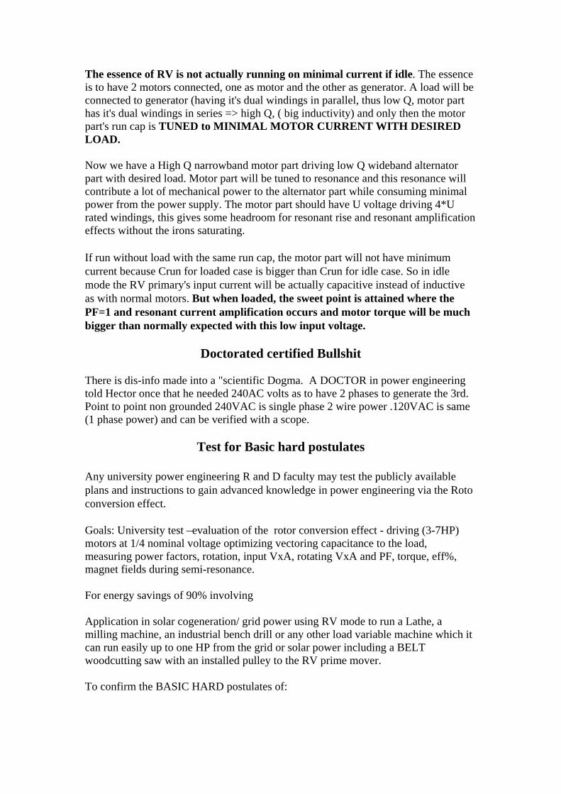
The essence of RV is not actually running on minimal current if idle. The essence is to have 2 motors connected, one as motor and the other as generator. A load will be connected to generator (having it's dual windings in parallel, thus low Q, motor part has it's dual windings in series => high Q, ( big inductivity) and only then the motor part's run cap is TUNED to MINIMAL MOTOR CURRENT WITH DESIRED LOAD. Now we have a High Q narrowband motor part driving low Q wideband alternator part with desired load. Motor part will be tuned to resonance and this resonance will contribute a lot of mechanical power to the alternator part while consuming minimal power from the power supply. The motor part should have U voltage driving 4*U rated windings, this gives some headroom for resonant rise and resonant amplification effects without the irons saturating. If run without load with the same run cap, the motor part will not have minimum current because Crun for loaded case is bigger than Crun for idle case. So in idle mode the RV primary's input current will be actually capacitive instead of inductive as with normal motors. But when loaded, the sweet point is attained where the PF=1 and resonant current amplification occurs and motor torque will be much bigger than normally expected with this low input voltage.
Doctorated certified Bullshit There is dis-info made into a "scientific Dogma. A DOCTOR in power engineering told Hector once that he needed 240AC volts as to have 2 phases to generate the 3rd. Point to point non grounded 240VAC is single phase 2 wire power .120VAC is same (1 phase power) and can be verified with a scope.
Test for Basic hard postulates Any university power engineering R and D faculty may test the publicly available plans and instructions to gain advanced knowledge in power engineering via the Roto conversion effect. Goals: University test –evaluation of the rotor conversion effect - driving (3-7HP) motors at 1/4 nominal voltage optimizing vectoring capacitance to the load, measuring power factors, rotation, input VxA, rotating VxA and PF, torque, eff%, magnet fields during semi-resonance. For energy savings of 90% involving Application in solar cogeneration/ grid power using RV mode to run a Lathe, a milling machine, an industrial bench drill or any other load variable machine which it can run easily up to one HP from the grid or solar power including a BELT woodcutting saw with an installed pulley to the RV prime mover. To confirm the BASIC HARD postulates of:

Postulate one: Normal motors waste 90% of their power with no load, RV saves 90% of this otherwise lost energy as a power on demand electrical transformer alike operation showing motors can be operated in resonance at a minimal Power draw, and supply power on demand Using Higher Impedance being 90% power savins idling 94% eff on loading at re rated HP. -measurement of 5 to 7.7 HP 3PH motors run in RV mode re-rated to 1 to 1.8 HP tuned at 749W per hp 97% eff as an approximate estimate tested by a method to measure foot pound torsion to HP to Watts conversion using a LAB volt Foot Pound torque meter or equivalent. To show and prove that under certain conditions of load & tuning conditions RV is OU (over unity). Point: To show motors can be operated as transformers at a minimal Power draw, and supply power on demand Using Higher Impedance. 90% power savins idling 94% eff on loading at re rated HP.
Accurate debunking via test equipment A ***start*** for basic research. By earl. 1) Measure the inductance of the winding to be resonated. 2) Couple the motor to a "rotary table" as the machinists call it. Rotate the motor in precise increments and note variations in inductance, including minimum and maximum. 3) Build a two-terminal oscillator with two transistors, a diode, couple of R's and C's. Cheap, easy, and simple. Below is a schematic.
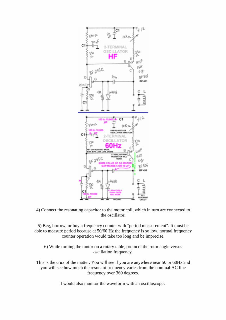
4) Connect the resonating capacitor to the motor coil, which in turn are connected to the oscillator.
5) Beg, borrow, or buy a frequency counter with "period measurement". It must be
able to measure period because at 50/60 Hz the frequency is so low, normal frequency counter operation would take too long and be imprecise.
6) While turning the motor on a rotary table, protocol the rotor angle versus
oscillation frequency.
This is the crux of the matter. You will see if you are anywhere near 50 or 60Hz and you will see how much the resonant frequency varies from the nominal AC line
frequency over 360 degrees.
I would also monitor the waveform with an oscilloscope.

Two further considerations provided by Phil Wood First: and which is fool proof is run time. This is when you run a motor in RV mode compared to the same motor and batteries run through a conventional 3phase inverter. Second: is using computer software and monitor all resistance blocks at the, in and out, where an average recording is calculated over a period of time. Phil states - I learnt something very important whilst going through professional 3rd party testing and that is, you can not fool or discredit run time with too 2 machines doing identical work with one having your concept and the other not. Then the motor and the batteries must be alternated and the same tests run again and again to eliminate any errors. There is so much to learn (R and D is needed) and understand, as when hitting true resonance and operating within its realms, effects will not be what you expect. This is what I personally have witnessed thousands of times where the original energy consumption may appear the same, but where the load is doubling its energy output. Other effects are temperature changes as energy is compressed and released.
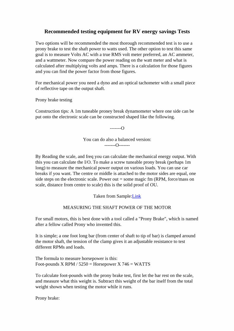
Recommended testing equipment for RV energy savings Tests Two options will be recommended the most thorough recommended test is to use a prony brake to test the shaft power to watts used. The other option to test this same goal is to measure Volts AC with a true RMS volt meter preferred, an AC ammeter, and a wattmeter. Now compare the power reading on the watt meter and what is calculated after multiplying volts and amps. There is a calculation for those figures and you can find the power factor from those figures. For mechanical power you need a dyno and an optical tachometer with a small piece of reflective tape on the output shaft. Prony brake testing Construction tips: A 1m tuneable proney break dynamometer where one side can be put onto the electronic scale can be constructed shaped like the following.
-------O
You can do also a balanced version: -------O-------
By Reading the scale, and freq you can calculate the mechanical energy output. With this you can calculate the I/O. To make a screw tuneable prony break (perhaps 1m long) to measure the mechanical power output on various loads. You can use car breaks if you want. The centre or middle is attached to the motor sides are equal, one side steps on the electronic scale. Power out = some magic fm (RPM, force/mass on scale, distance from centre to scale) this is the solid proof of OU.
Taken from Sample:Link
MEASURING THE SHAFT POWER OF THE MOTOR For small motors, this is best done with a tool called a "Prony Brake", which is named after a fellow called Prony who invented this. It is simple; a one foot long bar (from center of shaft to tip of bar) is clamped around the motor shaft, the tension of the clamp gives it an adjustable resistance to test different RPMs and loads. The formula to measure horsepower is this: Foot-pounds X RPM / 5250 = Horsepower X 746 = WATTS To calculate foot-pounds with the prony brake test, first let the bar rest on the scale, and measure what this weight is. Subtract this weight of the bar itself from the total weight shown when testing the motor while it runs. Prony brake:

Resting on scale and around shaft:
Close up of clamp:
Tensioner screw on clamp:

Clamped around shaft-disc:
Make it as light as possible - you don’t need Teflon as the wrap around part; you could make it of aluminium or brass. All you need is a drill press and bit the diameter of your motor shaft. When you do your Prony brake tests, rest the arm on the scale with. The motor not running and the brake very loose on the shaft then see how much it weighs, then subtract this weight from what the brake pushes the scale when you do the testing with the motor running. Hector says to make double-armed brake (two one foot arms at 180 degrees) , and have the other arm's purpose to be a perfect balance so that the arm resting on the scale will read O grams...this way you don’t need to subtract the weight of the scale itself, and the reading should be more accurate since there would be less drag on the shaft too. I haven’t made one like this yet, but it seems to be a better design. When you test, the RPMS measurement must be very exact, (use scope) as well as the grams or ounces that you read on the scale. when you insert the numbers in the formula, if you miss getting it right by just a bit, it will tweak the formula into an unbelievable way over OU or unbelievable way under OU so do a lot of repeat-tests, so that you can do it anytime in a flash and the readings are always going to be predictable.

A lube on the shaft too will help keep the RPMS steady (hemp oil?) Also its an AC motor surfing on a AC sine wave, so don’t over-brake it into heat build up and huge draw (what a debunker-lab would do like t) you'll find a certain RPM and shaft-loading that will be the best. I prony braked one of my kone-head motors way back in 99 at a FCC lab and what really made it better than normal motors is the lack of heat build up under heavy shaft loading, the draw was about 3 times less with same load on shaft. Thus the opinion by many engineers experienced in ALT energy is the best way and most accurate to compare shaft power in motors is a PRONY BRAKE which is just a 1 foot arm on your shaft, with one end of arm resting on a scale measuring grams or ounces, and the other end is wrapped around the motor shaft, with this end "split" so that a screw can go through it so that it can be tightened or loosened for different amounts of tension on the arm (tighter will make more pressure on scale, looser will make for less pressure on scale) Then calculate WATTS by knowing the RPMS (use scope) while pressure on scale is being measured, and knowing that you have a one foot long arm foot-pounds pressure is easy to see, then stick it all into the basic horsepower formula. Doug kone head has been using Prony Brakes for 7 years on motors – the idea has also been endorsed by JL Naudin who acquired it from patent that Mr Prony made long ago...it works great. Prony Formula by Raivo. Here is the prony break formula I used once (in metric): P = E / t = m * 9.8 * 2 * PI() * R * (RPM / 60) Simplified: P = 1.026223 * m * R * RPM Oversimplified: P = m * R * RPM m - scale reading R - distance from shaft to scale RPM - rotations per minute Output is in watts. Another Simple way is to use DC car generator (not an alternator) older cars like a 67 fiat as example used generators, nowadays they are all alternators. Simply run one motor with the generator, then the other with same generator and see how much power you make in comparisons. PROBLEMS anticipated with this: When doing true power tests, you need that capacitor, and the resistor, and your audience needs to UNDERSTAND how to measure true power (WATTS)...most people (actually maybe 1 out of 5 maybe) know that watts is volts X amps, and WATTS is true power, BUT the thing is, most people DONT UNDERSTAND that you need a resistive load (A RESISTOR) to check

power (WATTS) output from coils (what a generator has in it making that power) and also it should be rectified to DC too, to avoid meter errors and other problems....in fact I would say that if you put a thousand people who took science and electronics classes in high school in a room I would guess maybe 12 of those people understand how to check REAL POWER with a resistive load across your cap. So to me this is your biggest hurdle to overcome when you do your demos - basically your audience will not know what you are talking about and you must teach them how to test power – make sure they understand you and don’t think you are making it up.. Another solution is to use a PMI DC servo motors as your load on the shaft if you can’t get a car generator or use both. Update: 1. PRONY BRAKE Attach to RV aluminium, ca 8mm thick 'flywheel'. Make a 'scale type' brake: ====O=.=O==== . - centre O - neo magnets Attach one end to electronic scale. When you push it near the rotating flywheel, magnets will cause drag and aluminium will heat up. There are no things that get 'used'. Power is adjusted by the gap between scale and flywheel. 2. use the same RV + flywheel setup Other RV, alternator you have the flywheel with magnets. Now, you can have prime mover running and shift the alternator nearer and nearer to prime mover. This way you control the slip and RPM, so you can optimize the resonance and do light bulb standing wave test. Generator tests, at different RPM's and loads, etc Hector the inventor will agree to use a car battery, and then put an ammeter on it feeding an invertor, then run the rotovertor or other motor with the invertor, and then run both types of motors and then compare how much they consume while using the drill press. A drill press is good because the IDLE power saving advantage can be shown. A valanced arm one feet length from shaft centre taped as to force valance or weight transducer as to read foot pounds of torque . A system to adjust arm friction to rotating shaft. Formula:

To get from pound-feet of torque to horsepower, you need to go through a few conversions. The number 5,252 is the result of lumping several different conversion factors together into one number. First, 1 horsepower is defined as 550 foot-pounds per second (read How Horsepower Works to find out how they got that number). The units of torque are pound-feet. So to get from torque to horsepower, you need the "per second" term. You get that by multiplying the torque by the engine speed. But engine speed is normally referred to in revolutions per minute (RPM). Since we want a "per second," we need to convert RPMs to "something per second." The seconds are easy -- we just divide by 60 to get from minutes to seconds. Now what we need is a dimensionless unit for revolutions: a radian. A radian is actually a ratio of the length of an arc divided by the length of a radius, so the units of length cancel out and you're left with a dimensionless measure. You can think of a revolution as a measurement of an angle. One revolution is 360 degrees of a circle. Since the circumference of a circle is (2 x pi x radius), there are 2-pi radians in a revolution. To convert revolutions per minute to radians per second, you multiply RPM by (2-pi/60), which equals 0.10472 radians per second. This gives us the "per second" we need to calculate horsepower. Let's put this all together. We need to get to horsepower, which is 550 foot-pounds per second, using torque (pound-feet) and engine speed (RPM). If we divide the 550 foot-pounds by the 0.10472 radians per second (engine speed), we get 550/0.10472, which equals 5,252. So if you multiply torque (in pound-feet) by engine speed (in RPM) and divide the product by 5,252, RPM is converted to "radians per second" and you can get from torque to horsepower -- from "pound-feet" to "foot-pounds per second." The prony-brake rod centre must be pointing to shaft centre. Foot pound is measured from shaft CENTER 1 foot to weight transfer point at centre also of relative rod end ...(One foot). Use 2 rods to valance tool in centre, use adapter ring else you will have keyway eating your brake away as a router bit. If tool is perfectly valanced you don’t have to centre weight correction into the equation How do you convert engine torque to horsepower? Have you ever looked at the specs of an engine in a magazine and seen something like "this engine makes 300 pound-feet of torque at 4,000 RPM," and wondered how much power that was? How much horsepower are we talking about here? You can calculate how many foot-pounds of horsepower this engine produces using a common equation: (Torque x Engine speed) / 5,252 = Horsepower The engine that makes 300 pound-feet of torque at 4,000 RPM produces [(300 x 4,000) / 5,252] 228 horsepower at 4,000 RPM. But where does the number 5,252 come from?

To get from pound-feet of torque to horsepower, you need to go through a few conversions. The number 5,252 is the result of lumping several different conversion factors together into one number. First, 1 horsepower is defined as 550 foot-pounds per second (read How Horsepower Works to find out how they got that number). The units of torque are pound-feet. So to get from torque to horsepower, you need the "per second" term. You get that by multiplying the torque by the engine speed. But engine speed is normally referred to in revolutions per minute (RPM). Since we want a "per second," we need to convert RPMs to "something per second." The seconds are easy -- we just divide by 60 to get from minutes to seconds. Now what we need is a dimensionless unit for revolutions: a radian. A radian is actually a ratio of the length of an arc divided by the length of a radius, so the units of length cancel out and you're left with a dimensionless measure. You can think of a revolution as a measurement of an angle. One revolution is 360 degrees of a circle. Since the circumference of a circle is (2 x pi x radius), there are 2-pi radians in a revolution. To convert revolutions per minute to radians per second, you multiply RPM by (2-pi/60), which equals 0.10472 radians per second. This gives us the "per second" we need to calculate horsepower. Let's put this all together. We need to get to horsepower, which is 550 foot-pounds per second, using torque (pound-feet) and engine speed (RPM). If we divide the 550 foot-pounds by the 0.10472 radians per second (engine speed), we get 550/0.10472, which equals 5,252. So if you multiply torque (in pound-feet) by engine speed (in RPM) and divide the product by 5,252, RPM is converted to "radians per second" and you can get from torque to horsepower -- from "pound-feet" to "foot-pounds per second." Torque (FP) x Engine speed (RPM)) / 5,252 = Horsepower The engine that makes 300 pound-feet of torque at 4,000 RPM produces [(300 x 4,000) / 5,252] 228 horsepower at 4,000 RPM. But where does the number 5,252 come from? To get from pound-feet of torque to horsepower, you need to go through a few conversions. The number 5,252 is the result of lumping several different conversion factors together into one number. First, 1 horsepower is defined as 550 foot-pounds per second (read How Horsepower Works to find out how they got that number). The units of torque are pound-feet. So to get from torque to horsepower, you need the "per second" term. You get that by multiplying the torque by the engine speed.

But engine speed is normally referred to in revolutions per minute (RPM). Since we want a "per second," we need to convert RPMs to "something per second." The seconds are easy -- we just divide by 60 to get from minutes to seconds. Now what we need is a dimensionless unit for revolutions: a radian. A radian is actually a ratio of the length of an arc divided by the length of a radius, so the units of length cancel out and you're left with a dimensionless measure. You can think of a revolution as a measurement of an angle. One revolution is 360 degrees of a circle. Since the circumference of a circle is (2 x pi x radius), there are 2-pi radians in a revolution. To convert revolutions per minute to radians per second, you multiply RPM by (2-pi/60), which equals 0.10472 radians per second. This gives us the "per second" we need to calculate horsepower. Let's put this all together. We need to get to horsepower, which is 550 foot-pounds per second, using torque (pound-feet) and engine speed (RPM). If we divide the 550 foot-pounds by the 0.10472 radians per second (engine speed), we get 550/0.10472, which equals 5,252. So if you multiply torque (in pound-feet) by engine speed (in RPM) and divide the product by 5,252, RPM is converted to "radians per second" and you can get from torque to horsepower -- from "pound- feet" to "foot-pounds per second.
Phils DC to AC start with the BCSRC RV The following picture is of running a 3phase with a 12volt DC motor coupled. This gives immediate start up with no starting caps required, and when the 3phase is heavily loaded the slip causes the DC motor too work harder pulling the 3phase back up to speed. After running many tests with this, the results show it is highly efficient with "power on demand” characteristics.

Both motors run cold, note a chain drive is too noisy, the advice is to go belt driven . If you run the 3phase in RV with the following BCSRC circuit you won’t be disappointed.

Copy and enlarge for further detail. The instructions are to try 20UF caps on all phases for the 120volts 60 hertz motors. Note you may need to do some digging to find the centre Y in some motors. Australian motors are already setup for this configuration without hacking into the motor. All you do is connect the links as per this diagram.

Colour/Number codes are:
1), Blue 2), white 3), orange 4), yellow 5), black 6), purple
The following will mean you never will need a start cap as the DC motor automatically spools up the PM. When you load down the PM the DC motor automatically pulls it back up to speed. I have mine running like this, and even though it is belt coupled it doesn't matter as it is a one too one ratio Anyways. Now before anyone freaks out, the DC motor does not see 120volts but only the voltage it is rated for. Without getting complicated it is all just a resistance thing with the differential between the DC and AC motor. You will also notice that the current draw is much less than normal RV mode and there is much more torque. Now mate, if you want too also use the PMI as a generator, it is so damn easy. All you do is connect your next load, and lets say it is light bulbs across the DC motor. Why only 2 people would listen to me and try this I have no idea. But you will see how a tiny inverter will now start the PM and the current will fall way lower than before, and you can generate excess power from the DC motor with out any complications
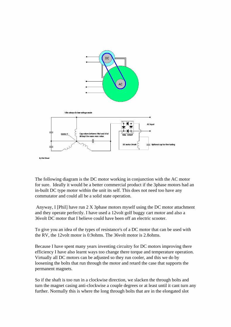
The following diagram is the DC motor working in conjunction with the AC motor for sure. Ideally it would be a better commercial product if the 3phase motors had an in-built DC type motor within the unit its self. This does not need too have any commutator and could all be a solid state operation. Anyway, I [Phil] have run 2 X 3phase motors myself using the DC motor attachment and they operate perfectly. I have used a 12volt golf buggy cart motor and also a 36volt DC motor that I believe could have been off an electric scooter. To give you an idea of the types of resistance's of a DC motor that can be used with the RV, the 12volt motor is 0.9ohms. The 36volt motor is 2.8ohms. Because I have spent many years inventing circuitry for DC motors improving there efficiency I have also learnt ways too change there torque and temperature operation. Virtually all DC motors can be adjusted so they run cooler, and this we do by loosening the bolts that run through the motor and retard the case that supports the permanent magnets. So if the shaft is too run in a clockwise direction, we slacken the through bolts and turn the magnet casing anti-clockwise a couple degrees or at least until it cant turn any further. Normally this is where the long through bolts that are in the elongated slot
between the magnets pull up against one side of the magnets .Once this is done, the DC motor has now got much more torque and will operate far cooler than ever before. It does slow the RPM down somewhat running on its own, but has no effect with the operation of the RV, as a natural balance takes place with RPM and voltage where both the RV and DC motor automatically stay in tune. It may be wise too put a conventional scientific explanation why the 2 motors run together in harmony, and why the current usage now drops down further in this operation, as I have a complete different understanding of energy that seems too confuse people further. LOL. Now close looping with the DC output too an inverter is a big NO NO. But there is a YES. First of all I will explain as best as I can why. Electrons have a form of memory where they do not like to be sent back to the original source. To close loop with the DC motor in this instance back into the inverter will blow the inverter out immediately. There are a number of ways too get around this, where we can either use an isolation transformer on the RV, or send the energy back into a different source, so there is no reference. Another thing I can assure you of from my experience is that you can also get runaway in this closed loop sequence.This is where the returning energy lifts the battery voltage by 2 or 3 volts which in turn lifts the output of the inverter by many more volts which in turn now lifts the returning energy by many more volts until where the battery is unable too hold a steady voltage being over charged. This is where something will blow. Anyway the solution is how I managed to get 3rd party reports showing that the BECS circuit was a minimum of cop1.6 too a maximum of cop1.9. This is where we use 2 batteries where they alternate, so one is running the load while the generated output is charging the other battery.After a short period of time we then switch in the charged battery to work, and switch in the other battery too now be charged. So with a simple relay circuit, the DC motor can be charging a second battery for some time, then this battery can latter be switched in too now run the inverter. Ok, so how do we regulate the charging of a battery where the voltage could be anything far higher than 14volts. This is as per the circuit I have attached where in series too the charging battery we connect a light bulb of what ever wattage we wish too use for charging. A standard voltage regulator wastes the excess voltage as heat, so the next best thing is too dump the excess voltage in the form of heat which also is producing light. When switching between batteries in this manor, it is essential too have a capacitor of a large value connected too the input power of the inverter. This is because there is a momentary delay as the relays switch,,, and the inverter requires a steady voltage.

Anyways, I hope this explains a few things so people can understand any safety issues and prevent damaging equipment like an inverter. I have also added the relay circuit and am hoping there is no mistakes.

Phils RV DC with AC set up
The 3 Phase finally unlocked by Phillip wood
To simplify the 3phase operation, I [Phil] will work with one small part of the rotor and break the phase relationships into square pulsed segments so you can see how simple it really is. The rotor consists of 2 dissimilar metals being Ferris and non-Ferris. When a magnetic field is activated over or near Copper or Aluminium it repels this metal pushing it away. Especially with Aluminium as it has a high stored mass of energy that was used too manufacture the product. This means that lets stay with

Aluminium; it is already saturated with energy and can not accept anymore charge. Also this is why these metals are used as conductors as the electrons travel around the metal and are not absorbed. With alternating dissimilar metals surrounding the rotor diameter, and when a magnetic field is activated we have 2 forces that exist. First we have a push against the Aluminium or copper strip and a pull towards the iron strip. The iron has a permeability enough too hold for the next polarity phase where the next magnetic field activated, not only forces against the Aluminium but pulls harder too the opposite polarity of the Iron magnetic field, until it becomes the same polarity as the magnetic field being activated. This is why a particular amount of slip is important too allowing enough time too cause saturation in the Iron of the coil polarity. The next simplicity is the use of dissimilar metals known as the Peltier Effect and the Seebeck Effect, whereby at the junction of them touching we have a temperature of hot on one side and cold on the other side. This is generated from the magnetic field working against the Aluminium (wrongly known as Eddy currents) but where if there is a temperature differential this generates a current. With this high current in place being generated, it amplifies the magnetic field within the Iron. Overall it is obvious why the 3phase motor becomes more efficient when approximately 2/3 loaded, as the effects within the rotor are increased due too a longer time interaction from the working magnetic field windings. This is a simple diagram of how the Iron becomes charged with the coil polarity and enhances the next phase operation.

With all this stated I realized the motors can be powered with DC pulsing and hence tested a few circuits too prove the operation can be performed on a simple scale, of driving all 3 phases just of one voltage polarity. The next thing that became obvious is that just like my Baldors motor it becomes 89.1% efficient when 75% loaded. Taking into consideration the power factor and the overall true wattage usage being paid for, it can be seen that a generator coupled too the motor that has an efficiency near the same as the motor used, will develop an efficiency exceeding COP1. This means it is a motor generator doing real work generating real power as is, being off the shelf with no modification regarding resonance circuits.

However if the concept is too be used with a standard off the shelf inverter, the reflected power from the motor can cause much damage too these devices. But utilizing an inverter with step up transformers and H bridge drive circuits, all reflected power will naturally be directed too the battery source.End
Anomaly readings from the RV based on Hectors teachings OU -RV coupled to a PMI disk PM, DC motor From Norman Wotan (Mon, 25 Feb 2002 – on Keelynet-rotoverter) Quote: I built Hectors phase Roto Verter with the following results: Motor is 3HP, 3 Phase, 60HZ, 1725 RPM, wired for operation on 480V. Motor free running, tuned to minimum current draw from 120V line input required 20mfd 370V oil filled cap resulting with a current draw of .66 amps @ 120VAC input. Motor loaded with belt drive step-up 6:1 ratio to drive a PMI disk PM, DC motor acting as a generator.
PMI Kollmorgen U12M4/9AF4T ServoDisc DC Motor � Part Number: 00-01246-013
� Serial Number: 3K11227 or 3K11228 � Manufacturers Lead Time: 10 to 12 weeks
� Retail Price: $1,708.00 Features:
� 38.3 to 402.5 oz-in. continuous torque � Motor lengths less than 2”
� 4.37” to 7.37” OD Round Frame U-Series ServoDisc™ DC motors employ the unique Kollmorgen/PMI flat disc armature. The ironless, low inertia armature delivers high acceleration and zero
cogging in an exceptionally compact package. � Extremely good speed control with zero cogging and low RFI
� Long Brush Life � Flat ServoDisc™ motors are ideal for many applications:
� Save space and weight in applications requiring a low profile motor

� Large torsional stiffness for precision control of speed and acceleration Specifications:
� Peak Torque: 1316 oz-in, 929 N-cm � Rated Speed: 3000
� Rated Continuous Torque @ 25° Celsius: 128 oz-in, 91 N-cm � Rated Continuous Torque @ 40° Celsius: 114 oz-in, 81 N-cm
� Rated Power Output: 284 � Maximum Recommended Speed: 6000
� Continuous Stall Torque: 122 oz-in, 86 N-cm � Cogging Torque: 0 oz-in
� Rated Terminal Voltage: 43.4 Volts � Rated Continuous Current: 8.8 Amps
� Peak Current: 85 Amps � Continuous Stall Current: 8.1 Amps
� Terminal Resistance ±10%: 0.750 Ohms � Armature Resistance ±10%: 0.610 Ohms
� Back EMF Constant ±10%: 11.55 V/KRPM � Torque Constant ±10%: 15.63 oz-in Amp, 11.04 N-cm Amp
� Viscous Damping Constant: 1.8 oz-in/KRPM, 1.3 N-cm/KRPM � Armature Inductance: <100
� Temperature Coefficient of KE: -0.02%/° Celsius Rise � Number of Cummutator Bars: 141
� Moment of Inertia: 0.0190 oz-in-sec², 1.34 kg-m² � Static Friction Torque: 5.5 oz-in, 3.9 N-cm
� Weight: 10 lbs. � Diameter: 5.50” in, 139.7 mm
� Length: 2.10” in, 53.3 mm � Peak Acceleration: 69.2 kRad/s²
� Mechanical Time Constant: 6.68 ms � Electrical Time Constant: <0.16 ms � Continuous Power Rate: 6.1 kW/sec
� Thermal Resistance at Rated Speed: 1.27° Celsius/Watt � Thermal Resistance at Stall: 1.90° Celsius/Watt
� Forced Air Thermal Resistance – with 2.0 lbs/min Forced Air: 0.23° Celsius/Watt Type 9FA4T Low Cost Analog Tachometer Characteristics: < /B>
� Output Voltage: 2.50 V/KRPM � Ripple Voltage Max (P-P) (1): 5.0% @ 1000 RPM, 5.0% @ 500 RPM, 5.0% @
100 RPM � Linearity of Output Voltage (Rated at 3600 RPM): .06%
� Bi-directional Tol (diff. in output V/KRPM): 3.0% � Output Impedance (Resistive): 1.18 Ohms
� Temperature Coefficient Output Voltage: -.19%/° Celsius Rise � Load Resistance (Recommended Min.): 1180 Ohms
� Tachometer Inertia: .0024 � Number of Cummutator Bars: 117
(generator unloaded) required 30 mfd, 370V oil filled cap with a resulting current draw of .50 amps @ 120VAC input. Now I loaded the DC generator with 160-watt incandescent lamp load. Since I have two independent systems here, one being driven

with 120VAC line input and the other system a belt driven DC generator being loaded with pure resistive load. Here are the numbers: Motor was retuned for minimum current draw which required 45 mfd, 370V oil filled cap with a resulting current draw of .15 amps @ 120VAC input. The independent generator put out .75 amps @ 74 VDC into a resistive load. The only thing that needs to be looked at on the input side of the equation is the power factor of the AC input. I need to look at the current/ voltage phase relationship. I'm satisfied with the figures that I calculate which shows roughly 18 watts AC input with a DC output of 55.5 watts. What I find most interesting is the fact that the more load you put on the 3-phase motor the lower the input current draw and the motor gets colder. The belt driven DC generator gets quite hot after about 30 minutes of running time. Go figure it out. I believe there is a lot to be learned about revolving magnetic fields in 3 phase motors and tuning the output via capacitors. This experiment is so easy to do everyone should seriously look at this phenomenon. My next step is to document PF on input and improve the DC side of the circuit to provide more loading. Be careful with loading of the prime mover. Make your belt coupling variable as to loading for you cannot load prime mover below its design slip speed. After loading to design slip speed you must adjust capacitance to new lowest current draw. Run capacitance will change after loading. –End quote. If trying let your belt system slip and ride in the slip speed of the motor. "Adjusting the slip with slack” and adjusting the pulleys with the slack as to fine its Sweet spot". Theory examination by Hector In the RV the frequency applied directly determines the speed, frequency synchronous speed minus % slip = load speed. The speed also is critical to find the OU potential in a GENERATOR, speed & load = (critical) adjust. OU in generators is manifested at a given speed with a specific LOAD where it is maximal in gain and performance and whereby it requires its lowest mechanical input to give its highest electrical one. Go back to tuning and get the best speed, best load for best performance. Also use different pulleys to get best speed for that particular generator, IMPORTANT don’t get fixed on one parameter One is RV the other is the generator. Asynchronous PM generator will put power into the system as power factor correction from the over unity magnetic amplification. Extract: lower intensity attractor field is charged by the approaching higher intensity magnetic field one. Lab test: a lab test indicates rotor lowers temperature at this state, indicating thermal energy transfer from electron spin to field induction one. (True magnetic amplification transformation) justified by book rules and thermodynamic law.

Synchronous speed is the absolute upper limit of motor speed. If the rotor turns exactly as fast as the rotating magnetic field, then no lines of force are cut by the rotor conductors, and torque is zero. ZERO (ZERO point energy) (Note here that when on 0 torque we have 0 power on a theoretical 0 current) being self induction, and NEGATIVE in relation to the rotary field. The VOLTAGE vector becomes a NEGATIVE resistance to the line power and contributes power to such source (seen as POWER factor correction on LOW impedance but as OU in matched hi impedance circuits.) When running, the rotor always rotates slower than the magnetic field. The rotor speed is just slow enough to cause the proper amount of rotor current to flow, so that the resulting torque is sufficient to overcome windage and friction losses, and drive the load. The speed difference between the rotor and magnetic field, called slip, is normally referred to as a percentage of synchronous speed: s = 100 (ns - na)/ns, where s = slip, ns = synchronous speed, and na = actual speed.
Dan’s tests Basic tests with loading one phase of the alternator with caps. I've 2x 5.5HP motors 3000rpm (50Hz) connected 1:1. This is a picture of the setup:
Here is a scope shot of the voltage and current in the PM (unloaded) The ‘clean’ sine is the voltage. The ‘dirty’ sine is the current.

I did some basic tests with loading one phase of the alternator with caps. I've 2x 5.5HP motors 3000rpm (50Hz) connected 1:1. The PM is wired in Y, with 120V input voltage (through variac as grid in 230V in EU). The Alt is also wired in Y, so I have as possible connections L1, L2 and L3. On the Alt, the caps are connected to L1 & L2. - Voltmeter is connected over L1 & L2 - Current clamp meter in line to L1 - scope Ch1: voltage on L1 - scope Ch2: current probe in line to L1 I did measurements with several cap values: 1) 290V 2.5A 725VA 30 uF 2) 380V 3.8A 1444VA 35 uF 3) 435V 5.5A 2393VA 45 uF 4) 444V 6.3A 2797VA 50 uF For the 1st and 4th, I made a small video of the scope measurements. The current sine wave is more or less static. For the voltage sine, notice a changing phase shift from 70° to 160° (leading to the current), as well as an amplitude fluctuation. This is at about 0.6 Hz. 4th: Here also the current sine wave is more or less static. For the voltage sine, again a changing phase shift from 80° to 120° (less than video 1), as well as an amplitude fluctuation although less pronounced than the first test. This is about 3.6 Hz. Because of the higher load, the generated frequency has gone down to approx 46 Hz (likely 4% slip in PM and 4% slip in alternator…).
Doug Konzen’s prony Break testing

For the third time I tested the 7.5hp Baldor motor with the series adding wiring which gives 5.9 ohms resistance to each phase. This time I tore the motor all the way down first, photographed the internal wiring and labels, and also oiled the bearings just a bit with some "Kroil" brand hi-tech lubricant.
The phases are wired in Y fashion - and the motor is run in Hector's roto vertor-mode with a 7UF run cap across lines 2 and 3. At 1650rpm no-load idle, the motor draws .3Aac @ 120Vac with the 7UF cap. Any amount of force from the prony brake that exceeds approx 80 ounces on the scale with the corresponding amps input of approx 2.3Aac will bring the motor to a stop. In this testing, and the previous too, it has been found that this particular RV'd 3ph 7.5hp Baldor AC motor only likes just a couple narrow "notches" of speed and torque being squeezed from the shaft by the foot-long Teflon-collar prony brake. And as before in the two earlier test-runs done this week, it was possible to keep a consistent force of 54 ounces (3.375LBFT) on the scale, which corresponds to a simultaneous reading of 1 Aac @ 120Vac input to the motor showing on the meters. And also a force of 43 ounces (2.687LBFT) and the simultaneous .8 Aac @ 120Vac input to motor on the meters was another narrow notch-of-power from the shaft to extract. So again, it is almost a full HP (746watts) of shaft-power from under 120 watts electrical input, and still haven’t tried out more UF values to the run-cap in order to fine-tune it to the load.
RESULTS:
1/20/2007
120VAc grid-power input 7.5HP Baldor motor
.81 power-factor rated showing on label (stock rating)
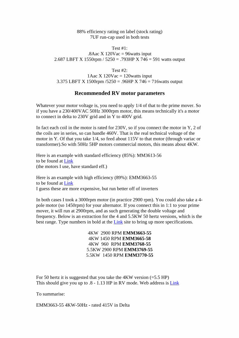
88% efficiency rating on label (stock rating) 7UF run-cap used in both tests
Test #1:
.8Aac X 120Vac = 96watts input 2.687 LBFT X 1550rpm / 5250 = .793HP X 746 = 591 watts output
Test #2:
1Aac X 120Vac = 120watts input 3.375 LBFT X 1500rpm /5250 = .96HP X 746 = 716watts output
Recommended RV motor parameters
Whatever your motor voltage is, you need to apply 1/4 of that to the prime mover. So if you have a 230/400VAC 50Hz 3000rpm motor, this means technically it's a motor to connect in delta to 230V grid and in Y to 400V grid. In fact each coil in the motor is rated for 230V, so if you connect the motor in Y, 2 of the coils are in series, so can handle 460V. That is the real technical voltage of the motor in Y. Of that you take 1/4, so feed about 115V to that motor (through variac or transformer).So with 50Hz 5HP motors commercial motors, this means about 4KW. Here is an example with standard efficiency (85%): MM3613-56 to be found at Link (the motors I use, have standard eff.) Here is an example with high efficiency (89%): EMM3663-55 to be found at Link I guess these are more expensive, but run better off of inverters In both cases I took a 3000rpm motor (in practice 2900 rpm). You could also take a 4-pole motor (so 1450rpm) for your alternator. If you connect this in 1:1 to your prime mover, it will run at 2900rpm, and as such generating the double voltage and frequency. Below is an extraction for the 4 and 5.5KW 50 hertz versions, which is the best range. Type numbers in bold at the Link site to bring up more specifications.
4KW 2900 RPM EMM3663-55 4KW 1450 RPM EMM3665-58 4KW 960 RPM EMM3768-55
5.5KW 2900 RPM EMM3769-55 5.5KW 1450 RPM EMM3770-55
For 50 hertz it is suggested that you take the 4KW version (=5.5 HP) This should give you up to .8 - 1.13 HP in RV mode. Web address is Link To summarise: EMM3663-55 4KW-50Hz - rated 415V in Delta

- so each winding is rated 415V - if you run this as PM in delta, you need to feed it with about 100-115V - if you run this as PM in Y, you need to feed it with about 205-230V - as Alternator: wire in delta Comparing the following 2 motors: A) EMM3663-55 * It is delta-Y 6-lead, 4KW (5.5HP), 230/414V, 50Hz, 89% eff. * is a very common motor around the 50Hz world (in EU, AU, etc...) (I remember that the '55' suffix means it's an Aussi motor...) * as PM-RV, wire in Y (=414V) (BUT in RV-mode each phase sees 2 coils in series, and as each coil is rated 230V, the RV-mode 'sees' 460V), and feed with 1/4 of that which is about 110-115V 50Hz * as Alt, wire in delta B) M3613T-50 * Is a dual coil motor 12-lead, 5HP, 220/380/440V, 50Hz, 85% eff. * is not a common motor in the 50Hz world (EU, AU) * can be wired in many ways (Link): 1- dual-Delta (means coils in parallel and in delta); so is wired for 220V, and feed with 55V NOT recommended for RV - too low V, too high current, too big caps needed 2- dual-Wye (means coils in parallel and in Wye); so is wired for 380V (in RV-mode is seen as 440V as coils are in series because of Wye) Feed with 110V 50Hz - so good for use where grid is 110V or with +-110V inverter 3- single-Delta (means coils in series and in Delta); so is wired for 440V feed with 110V (see above) - between these 2 configs (2 & 3), best is dual-Wye 4- single-Wye (means coils in series and in Wye); so is wired for 760V (this mode in Unsupported by Baldor, but again they don't know RV mode) RV-mode sees this as 880V; so feed with 220-230V 50Hz - so good for use where grid is around 230V or with +-230V inverter In summary: - Motor A is common to be found as surplus, and is an excellent choice for RV DEMO, where you can say to use a standard Wye/Delta motor (so does not have to be Baldor at all). This is the reason why I recommended this; Drawback is that this motor is less flexible in wiring options, and can only be fed with around 110V in RV-mode. So you need such a grid V, or inverter or transformer. -Motor B is very UNCOMMON in the 50Hz world, so is difficult to find (cost?). Technically it is a better RV motor, as you can wire so to connect straight to a +-230/240V grid. If you want reliable input power measure, then you need to connect anyway to an inverter and measure the power from the battery.

H's recommendation for motor B is also very right, but thinks about it being 'uncommon' if advertising the concept to the general public. RV 60 Hertz range. Best motor performance tested so far is 230/460 VAC 7.5HP 3450- or 1725 RPM 3PH motors 184 TCH frame (with removable external fan Specifications: baldors motor EM3770T
Catalogue Number: EM3770T Specification Number: 07H002X790
Horsepower: 7 1/2 Voltage: 230/460
Hertz: 60 Phase: 3
Full Load Amps: 19/9.5 Usable at 208 Volts: N/A
RPM: 1770 Frame Size: 213T
Service Factor: 1.15 Rating: 40C AMB-CONT
Locked Rotor Code: J NEMA Design Code: A
Insulation Class: F Full Load Efficiency: 91.7
Power Factor: 81 Enclosure: TEFC
Baldor Type: 0735M DE Bearing: 6307
ODE Bearing: 6206 Electrical Specification Number: 07WGX790 Mechanical Specification Number: 07H002
Base: RG Mounting: F1
Bottom line is you need DOUBLE COIL motors - this means, that the motor should have 9 or 12 wire terminals and two identical motors. That's why Hector has stated that it should be 230/460V model - when the dual coils are connected in series, then it is 460V (good for RV prime mover), when in parallel, then it is a 230V motor with twice the amps capacity (excellent for RV alternator operation). Such double coil motors might be a bit hard to find in Europe or in Australia. It is advisable to stick to the modelled guide and to order those US 230/460 motors. The above is the motor that Hector recommended (it's a 1770RPM motor which is a bit more peaceful to operate - less vibration, especially when the coupling between motors is not very good) Current recommendations from EVGRAY on RV motors to use: NA: - DUAL winding motors 230/460VAC 60Hz; 3 to 7.5HP - prime mover 3600rpm, wired for highest voltage (460V 'Y') and apply single-phase 110V

- Alternator 3600rpm or lower, wired for lowest voltage (230V) EU: - WYE/Delta motors 230/400VAC 50Hz; 5 to 10 HP - Prime mover 3000rpm, wired for highest voltage ('Y') and apply single-phase 100-120VAC (through variac or transformer) - alternator 3000rpm or lower, wired for lowest voltage (in DELTA) In any case the lowest HP is 5HP for 50Hz, as you need to have the same efficiency. (with 60Hz, you can go down to 3HP).So a 4KW 50nhertz motor will do. For Additional Technical explanations of the RV alternator and more please consult Dans E-book RE-OU 6.1 available at the EVGRAY yahoo energy group or the RVreplication yahoo group in the files section.