rotaries vs recips2 - pictech trading · i am sorry to state that so far we do not have a liquid...
TRANSCRIPT

1
R O T A R Y C O M P R E S S O R S
By Marjan Shek INTRODUCTION
The rotary compressor concept was invented before the 1st W. W., however, due to lack of advanced technology, it
was only about 20 years ago that the first rotaries appeared on the market. It has since almost completely replaced
the reciprocating type. All new air-conditioning units that are manufactured around the world in 2kW to 7.5kW
cooling capacity feature rotaries, so it is only a matter of time till “recips” will reside in our memories only.
Rotary’s success is contributed to several factors: they are smaller and lighter, they are more efficient, more
resistant to liquid refrigerant presence and they tolerate higher working temperatures. This has not been achieved
merely by the way the vapour gets compressed, but rather that the whole concept of a hermetic compressor has
been re-designed.
ROTARY VS RECIPROCATING
There are two types of rotary designs: the one with fixed vane and the one with turning vane(s). Since the one with
turning vane(s) is not in production any more, we will concentrate on the fixed vane type only.
In reciprocating type, returning gas enters the compressor housing and on its way to cylinder(s) cools down the
casing, electric windings and oil. The vapour then gets sucked via suction reed(s) by a downward moving piston.
The compression begins with an upstroke and ends when the piston reaches TDC and the compressed gas gets
discharged into manifold and out to condenser.
Weakness of this design is its vulnerability for liquid refrigerant related damages. Especially floodback: during an
on-cycle when the amount of superheat is insufficient the droplets of non-evaporated refrigerant pour in. At first
they evaporate and by doing so, the compressor’s temperature descends. The lower the temperature, the more
droplets escape evaporation and soon they mix with oil, wearing all bearing surfaces. Many of these droplets get
sucked into cylinders. Here they position themselves on top of the upward moving pistons and smash the valve
reeds at the speed of a Boeing. The impact creates disastrous pressure in all directions and inflicts multiple
damages. Dented suction valve reeds damaged piston crowns and conrods pins are the usual casualties. During the
off-cycle, on the other hand, the refrigerant migrates to the crankcase and creates havoc on start-up (Liquid
Washout, Slugging). Unfortunately, refrigerant migration is bad news for all compressors types.
In rotary compressor: the returning gas first enters a suction line liquid accumulator that is fixed to the
compressor’s casing and from there it gets sucked directly into the compression chamber. The suction line liquid
accumulator’s primary function is to compensate during the reversed cycle for the volumetric difference between
the condensing and evaporating coils. However, it successfully doubles – like shown later, as a liquid inhibitor. In
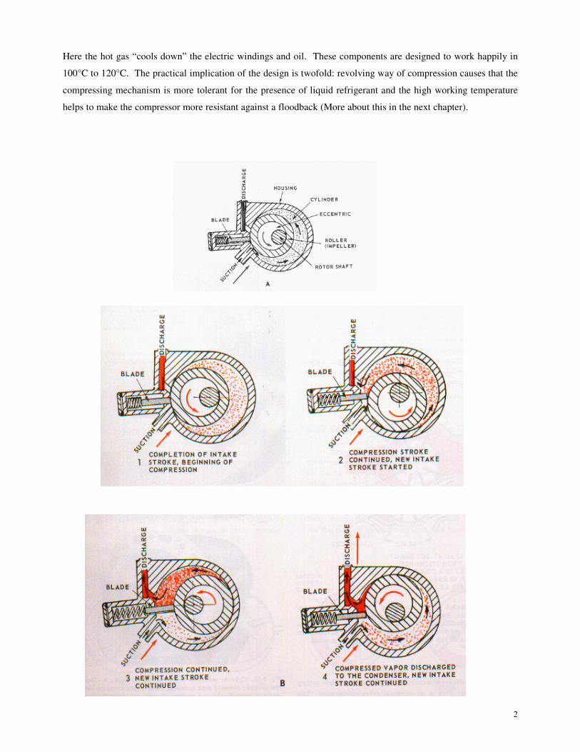
the chamber, an eccentric shaft rotates a roller in a cylinder (Fig1). Extremely high tolerances - .01 mm made it
possible to do away with sealers. As the roller (also called an impeller or rolling piston) revolves, the blade traps
quantity of vapour and compresses it into an ever-decreasing space, building up pressure and temperature. Finally
the vapour is discharged through the exhaust port into the compressor housing.
2
Here the hot gas “cools down” the electric windings and oil. These components are designed to work happily in
100°C to 120°C. The practical implication of the design is twofold: revolving way of compression causes that the
compressing mechanism is more tolerant for the presence of liquid refrigerant and the high working temperature
helps to make the compressor more resistant against a floodback (More about this in the next chapter).
3
It is important to add that a new generation of oil had to be devised – Suniso, Clavus, etc, – to cope with these
demanding conditions: de-waxed oil, that allows it to work at 120°C or higher without braking down. It is
important to notice here that although it will not carbonise at temperatures above 140°C, it will thin to the point of
loosing its lubricating properties. (Chemical brake-down occurs between 180°C and 200°C).
The other important change that transpires from this design is a better oil management. Unlike in the reciprocating
compressor, where 3% of the total discharged volume is oil that gets pumped out with each stroke of the piston into
the system and then must be retuned back; the rotary lets very little oil out. This decreases lubrication-related
problems so often found in reciprocating compressors
LIQUID REFRIGERANT AND ROTARY COMPRESSORS
I am sorry to state that so far we do not have a liquid proof compressor, just an improved degree of resistance to
liquid, as compared with the reciprocating design. Rotaries are no exception here. Though they can fight back a
mild floodback, their vulnerability lies in refrigerant migration and heavy floodback.
ROTARY & FLOODBACK
LIGHT FLOODBACK
Perhaps the main achievement of this design is the compressor’s bigger re sistance to liquid related problems.
Rotary compressor is able to fend off a light to mild flood-back that would completely destroy a
reciprocating compressor.
Due to its design, the rotary’s casing working temperature is about 100°C. This heat is transfe rred via radiation and
conduction to liquid accumulator and keeps it warm. That helps to evaporate (flash) the liquid refrigerant droplets,
before they might get sucked into the compression chamber. But even if a few droplets have made it so far, the
working temperature in the cylinder would certainly flash them into oblivion. The danger here is that light
floodback will turn into heavy floodback. More about this danger later on.
Ironically, this liquid repelling - high temperature is an “unwelcome” change for many technicians, because for
them, gone are the good old days when just by feeling and touching a compressor, they could say whether the
system was properly charged. (Some claim that they are able to achieve the same just by feeling and touching the
suction line alone. Only Gods know how many compressors they have sent to the nearest scrap yard). Well, they
better reform, because the only professional way to charge the system equipped with a rotary is by measuring the
suction line superheat.

4
HEAVY FLOODBACK
A heavy floodback unfortunately will have a more profound effect. I am referring here to a floodback caused, for
example, by non-rotating evaporating fans*. Both the evaporating pressure and temperature drops down and a
myriad of un-evaporated droplets attack the liquid accumulator and compression chamber. At first very little
happens, the high temperature in the cylinder evaporates them. Son, however, this picture will change: Together
with evaporating pressure the condensing pressure will drop and with it discharge temperature. Now, constantly
evaporating droplets start to freeze the entrance and move further into cylinder, freezing an ever-bigger zone.
Though discharge temperature will always stay high enough to discharge all the droplets out of chamber in form of
vapour, those droplets that hitch a hike on the roller will wash it dry of oil. As above, wear and tear will occur and
if nothing is done fast to fix the problem – another compressor bites the dust.
One can easily visualize what would have happen to a reciprocating compressor in a similar scenario.
*Clogged air filter, dirty evaporator, lack of load, badly overcharged system etc, will have the same effect.
ROTARY & REFRIGERANT MIGRATION
There are conflicting theories out in the field as to what the term means; so let me throw in my definition: It is a
movement of refrigerant – vapour or liquid - during the off-cycle, within the system. It is “powered” by
refrigeration oil that resides in the compressor crankcase and soaks up the vapour, turns it into liquid and then soaks
up some more and more and more. Its intensity will depend on ∆t between indoor and outdoor units, length and
design of installation etc. If the conditions for migration are inductive, the liquid refrigerant with oil on top will fill
up the compressor’s housing right to the brim.
Receip’s discharge valve(s) guard the entrance to crankcase what is not the case with the rotaries. On the suction
side there is some amount of liquid refrigerant that condensed in the pipe Mixed with oil it will slowly trek towards
compressor and settle in accumulator. The vapour will answer the irresistible oil call and find its way down to the
crankcase.
Regardless what type of compressor – they all are vulnerable to refrigerant migration.
The only way to avoid this phenomenon is to install the CRANKCASE HEATER.
.
MODERATE MIGRATION
In case of moderate migration, the following scenario will unfold:
The refrigeration oil in the crankcase draws vapours molecules from the hot gas pipe and transform them into
liquid. Then, on the suction side, the liquid/oil mixture will find its way from the liquid accumulator to
compression chamber through an orifice provided for oil return. From here, it will leak through the discharge reed
assembly that in most rotaries is located in the bottom plate, and into crankcase when it will join the one that got
soaked up by the oil. Of course not all of it will disappear and part of the mixture will cover roller and chamber
walls. During the start-up the roller will sweep it and push towards the discharge reed and through it to compressor

5
housing when it will soon evaporate. A similar action in piston compressor would have most likely smashed the
suction reed and damaged the piston and conrod. It will not in rotary because, unlike a piston, the roller in its
compression stroke squeezes it rather than hammers it.
HEAVY MIGRATION
When dealing with a long and badly designed pipe run that produces plenty of liquid, the scenario will look
somehow different: as above, at first it will leak through the orifice into cylinder and then, through the discharge
valve and into crankcase, with no serious danger to compressor. But as more and more of liquid passes through, it
washes off the oil film of the roller and chamber walls. Then, if it continues the level of liquid in crankcase will
top the discharge reed and from now on, the new liquid flowing to compression chamber gets trapped there. Soon,
the cylinder is flooded by liquid refrigerant. This in addition to liquid soaked up from the hot gas line. Amazingly,
the rotary compressor can actually survive this assault during the start-up. What would have completely destroyed
a piston compressor will not necessarily destroy the rotary. Of course, the amount of liquid now is too great for the
roller to squeeze it through discharge port so the surplus escapes to the suction side by pushing the vane and spring
back (that is when you hear this terrible, rattling noise). Once on the suction side of the vane, it mixes with more
freshly sucked liquid, gets squeezed and so on. This will last until all the liquid that has accumulated will get
sucked into cylinder. The result – if you “lucky” - a temporary oil washout and some often serious wear and tear
due to lack of lubrication. If you are not, mechanical damage, like a broken spring and /or malfunctioning vane
will occur. However, one has to keep in mind that if the problem is not solved this scenario will repeat itself day
after day and destroy the compressor.
Discharge assembly smashed by liquid – result of off-cycle migration
It is important to mention here that in some makes of rotaries, the discharge valve is located in the top plate rather
than the bottom. That allows the liquid to gather in the compression chamber and a similar damage as described
above will occur during every start-up even in the case of very moderate migration, seriously shortening
compressor’s life span. See the picture above.
As mentioned above the migrating refrigerant vapour, if unchecked, might completely fill up compressor casing.
This liquid will not penetrate to the compression chamber because the discharge valve will not let it in. The danger

6
here is that the liquid refrigerant will lift oil up and on the start-up it is oil first to leave compressor. Then, before
all this liquid will get pumped out, the bearing surfaces will get washed dry. The chances here to return oil back
into crankcase and resume a normal operation are zero.
S U MMAR Y
Rotary will endure higher discharge temperature and handle a presence of liquid refrigerant better then
reciprocating type. It is lighter and smaller and more efficient. It also controls oil better.
Is it a better compressor then reciprocating type? Perhaps. But it is important to remember that a properly handled
recipe will happily work for 15 years or more. I know instances where they remain serviceable after 30 years.
Rotaries haven’t even being around for so long!
However, I believe, the rotaries construction make them more resistant to small human errors and system’s
mischief. And, yes, perhaps a rotary you have just installed, and done a good job on it, will still run in 2022!
In next chapter: the most frequent failures in rotary compressors and how to avoid them.
In the October and November issue we concentrated on a general look at the rotary compressor, its strengths and
weaknesses. In this issue we look at the rotaries’ most frequent failures.
MOST FREQUENT FAILURES
Symptoms of failed compressors, as found on site, are usually similar: compressor turning but not pumping, noisy,
will not start, etc. It is so because of all the typical, mechanical failures – HDT, Floodback, Wet start – one way or
another lead to lubrication problems. Symptoms though, will not tell you what the actual cause of failure was. Only
a minute examination of the compressors inner parts will reveal the cause. If one is not equipped for this kind of
job, you should get a professional to do it for you. It is a critical piece of information in order to avoid having the
same problem with the replacement compressor.
HIGH DISCHARGE TEMPERATURE
Temperature in the compressor gets so high it thins the lubricant and cakes mixture of debris like epoxy, soot and
varnish from overheated windings; and white metal, aluminium and steel dust from bearing surfaces, into carbon-
like substance that often deposits at discharge valve.
TYPICAL SYMPTOMS:
θ Compressor will not start
θ Compressor will not pump
θ Windings down to earth
θ Blown terminals

7
TYPICAL DAMAGE TO COMPRESSOR:
θ Leaking discharge valve
θ Scored or seized bushes
θ Worn or scored roller and blade
θ Burned, overheated electric motor
θ Rotor drag
θ Oil dirty (metal shavings, soot) Badly overheated working parts
What is missing in the above litany of damages is “carbonised oil” that would be the most conspicuous item in
reciprocating compressor suffering from HDT. It is because the oil used in rotaries is of de-waxed type that will not
carbonise even at very high temperature. Unfortunately, above 140ºC, it thins to the point of loosing its lubricating
properties.
A Correct temperature of electric motor windings and oil depends on the gas discharge temperature that in turn is a
function of suction gas temperature and compression heat. There are two sources of the HDT problem: high suction
superheat or high discharge pressure and it is important to be able to distinguish which one is responsible for your
overheated compressor in order to go straight to the problem. Lets have a look at what system faults can lead to
these problems:
HIGH SUCTION GAS SUPERHEAT:
θ System short of gas
θ Blockage in liquid or suction line
θ TXV problem (stuck in closed position)
CONDENSING PRESSURE:
θ Systems overcharged with refrigerant (TXV)
θ Dirty, scaled condensing coil
θ Non-condensables in system
θ Condensing fan not turning
θ High ambient
θ High evaporating on-coil temperature (high load)
Of course there is nothing else you can do when confronted with this type of damage but to replace the compressor,
however, do yourself a favour and try to figure out what started this mess. Finding and fixing the problem will
prolong the life of your replacement. You can safely assume that one simple devise: the discharge temperature
thermostat that was supposed to save this compressor was a) faulty, b) bridged out, c) was not there at all.
Surely, the device will not fix the problem, but it should give you enough warning time for you to fix it. Here’s a
comforting thought: some makes of rotary compressors are equipped with an internal high-temperature, high amps
protection. The device opens up at 143ºC and closes back at 85ºC, approximately 40 minutes later, what offers an

8
excellent protection. (There is no time-lag when triggered by high current only what may lead to compressor short-
cycling and consequently burn-out).
Warning:
After a severe burnout inside of a compressor and the entire system looks a mess: Metal shavings, epoxy and soot.
There is no way one can get away without proper cleaning.
PRESENCE OF LIQUID REFRIGERANT IN ROTARY COMPRESSORS
Cleverly designed as they are, rotaries are not liquid proof. As said in the previous issue, rotary compressors will
effectively fend-off a mild flood back but sadly will succumb to heavy floodback or refrigerant migration. Still, in
my opinion, the rotaries ability to fight light and heavy floodback is an extremely important achievement of the
design. Considering the fact that floodback is killer #1 among reciprocating compressors (at least those employed
in the systems with capillary tubes), this feature only should make it a compressor of choice.
FLOODBACK
Damage caused by liquid refrigerant returning to compressor during the running cycle.
TYPICAL SYMPTOMS:
θ Compressor will not pump
θ Compressor will not start
θ Compressor is noisy
θ Windings down to earth
TYPICAL DAMAGE:
θ Worn / scored roller and cylinder walls.
θ Worn / scored, sometimes stuck blade
θ Worn plates
θ Scored crankshaft
θ Dragged rotor Worn bottom plate
θ Overheated or burned motor
Liquid refrigerant droplets constantly bombarding the entrance to compression chamber evaporate and freeze the
zone, finally letting the liquid refrigerant reach the chamber. Here, it washes off the oil off rolling piston, cylinder
wall and blade. If unchecked, this will destroy the compressor’s pumping ability. This will lead to scored bearings
and rotor drag, in-ability to return oil back etc.
The following can cause heavy floodback:
θ Dirty or blocked evaporator air filter
θ Dirty or blocked evaporating coil
θ Evaporating fan (motor) out of order
θ Defrost device not functioning (reversed cycle)

9
θ TXV wrongly adjusted or loose bulb
θ TXV oversized
What to look for to spot the problem during service:
An easy one to detect even without any measuring equipment: the compressor’s body feels coldish to the hand
touch. It can even emit rattling noises. Correction should be easy if you check system for the above-mentioned
faults.
WET START
The result of refrigerant migration during the off cycle. The refrigerant gathers in liquid form at the bottom of
crankcase or in the case of heavy migration, it overfills the suction accumulator and flows directly into the
compression chamber.
TYPICAL SYMPTOMS:
θ Compressor will not pump
θ Compressor will not start
θ Compressor is noisy
θ Windings down to earth
TYPICAL DAMAGE:
θ Worn / scored, sometimes stuck blade
θ Worn / scored roller or cylinder walls
θ Scored bearings
θ Scored crankshaft
θ Dragged rotor
θ Overheated or burned motor Worn blade
Liquid refrigerant will migrate to the compressor through the discharge pipe, suction accumulator or both.
If migration takes place through the discharge pipe, the refrigerant will gather at the bottom of the crankcase, under
the oil, lifting oil up. Depending on its quantity, it will lift the oil above the bottom bearing or even the top
bearings.
This event robs bearings of lubrication during the start-up. Of course, the compressors temperature rises very fast
after the start-up and evaporates all gathered liquid, but never fast enough to completely stop the damage. Liquid
refrigerant that found its way into the compression chamber and gets caught there during the start-up, (that depends
on its quantity and location of a discharge valve), is taken for a violent spin around the chamber. On its way, it
washes off the oil film of compressing assembly. When the amount of liquid is small, the roller will simply squeeze
it out through the discharge valve and into the crankcase, before it manages to inflict too serious damage. In case of
a bigger quantity, not all will fit through the valve and the remainder will go for a marry-go-round trip forcing back
the dividing blade and landing up again on the suction side, wearing, tearing and scoring blade, roller, cylinder and
top and bottom plates. (See the picture)
10
In the extreme cases it will smash discharge valve assembly.
This process was more detailed in the previous issue of this magazine. The following can cause refrigerant
migration into compressor:
θ Lack of / or faulty crankcase heater
θ Too long vertical piping without oil traps
θ Leaking liquid line solenoid valve, etc.
WHAT TO LOOK FOR TO SPOT THE PROBLEM DURING SERVICE
Noise during the compressor’s start -up is a give-away. Another clue is compressor temperature: if after several
seconds the compressor is not pretty hot, the presence of liquid refrigerant might be suspected.
LUBRICATION
Although, as mentioned above, a rotary compressor’s oil management is much better than reciprocating ones,
some oil will join gas on the trip around the system and may not return.
TYPICAL SYMPTOMS
θ Compressor is noisy
θ Motor down to earth
θ Compressor will not start
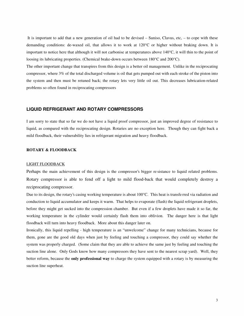
TYPICAL DAMAGE
θ Scored, worn bearings
θ Scored, worn crankshaft
θ Scored, worn roller, cylinder and plates
θ Scored, often stuck blade, broken spring
θ Rotor drag Lubrication problem
θ Burned electric motor
Lubrication problems originate from refrigerant migration, high discharge temperature, off cycle oil migration or
failure to return oil back to compressor. Not necessarily in this order.
It is important to establish the prime cause in order to protect replacement compressor from similar fate.
Compressors should be cut open and examined by professionals.
The following can lead to lubricating problems: Gas velocity too small to pick up the oil:
due to lack of refrigerant in the system or blockage, due to oversized suction line, lack of oil traps in long vertical
lines, short cycling, also, see Floodback and Wet Start.

11
MOISTURE
Presence of moisture or water in compressor
TYPICAL SYMPTOMS:
θ Compressor is noisy
θ Trips earth leakage
TYPICAL DAMAGE:
θ Copper plating or rust on steel surfaces
θ Scored bearings
θ Scored crankshaft
θ Burned electric motor Copper plating
Presence of moisture in the compressor will lead to corrosion of steel parts. It will also mix with the oil lowering its
lubricating properties. Soon, coupled up with high temperature, it will lead to copper plating.
The following can leave a moisture / water presence in the compressor:
θ Careless, sloppy installation / compressor replacement
θ Neglecting to vacuum the system
ELECTRIC MOTOR PROBLEMS
There are several types of winding burnouts that are listed below in the order of frequency.
Sadly, the most frequent failure is a start winding burn in brand new replacements.
START WINDING BURN
Only the start winding has burnt due to excessive current flowing through it.
This is by far the most common single-phase motor failure and can be initiated in many ways:
θ Terminals miss-wired
θ Faulty or too small capacitor
θ Pressures not equalised
θ Short cycling
θ Compressor not turning or partially seized
θ Faulty contactor
θ Low voltage
Start winding burn

12
RUN WINDING BURN
Although run winding is burnt, it often appears as a general burnout. This is due to the fact that the temperature of
the burning run winding is so high it partially burns the insulation of the start winding too.
The following can lead to this type of burn:
θ High load ( see HDT)
θ Faulty run capacitor
θ Compressor labouring due to poor lubrication
θ Faulty contactor
θ Low, high voltage
Warning:
All high temperature / high current motor protection devices are of bi-metal type. When triggered by a combination
of both, or high temperature only, the device will close back from 30min – 60min later. That gives a motor
excellent protection. When, however, triggered by excessive current only, not accompanied by high temperature,
the device will close a few seconds later, only to open again almost immediately and close and open etc.
Unfortunately in a situation like this, the device will not offer much of a protection.
INSULATION FAILURE
Failure, confined to a small area, being a result of the following:
θ Contaminants
θ Abrasion
θ Vibration
θ Voltage surge
θ Capacitor discharge (only when start capacitor is used)
REPLACING COMPRESSORS
STEP BY STEP PROCEDURE
Remove faulty compressor and establish the cause of its fault. If this is not something obvious like a whole in the
piping or a dirty condenser and you are not sure, get it examined by specialists (try AC Compressors advertising in
this magazine).
If high discharge temperature was diagnosed as a problem, the entire system will need to be cleaned.
Here is how:
θ Remove liquid line filter-dryer, TXV / capillary tube, reversing valve, check-valve.
θ Discard filter-dryer and capillary tube. Inspect and clean or replace other parts.
θ Blow separately condenser and evaporator in reverse direction from normal refrigerant flow. (this is to
remove all residual contaminated oil).
θ Install oversized liquid line filter dryer and suction line filter.
If the above is not necessary go to check out procedure.
13
CHECK OUT PROCEDURE
Inspect terminals, wires and components. Look for signs of overheating or flashing. Be sure that dirt, carbon or
oxides have not lodged between terminals. Inspect each wire for discoloration due to overheating, cuts, damaged
insulation, etc. Replace if necessary.
θ Check all f uses and fuse clips.
θ Check circuit breakers. Make sure they are of proper type and size.
θ Inspect contactors and overloads.
θ Check relays.
CAPACITORS
Check all capacitors. If bulged or leaking – replace. If visually okay remove wires going to connectors and connect
ohmmeter across terminals.
θ If needle does not move – capacitor is open and needs to be replaced.
θ If it swings to zero and stops there – capacitor is shorted. Must be replaced.
It should swing to a low or no resistance value then climb to a measurable resistance and stop there.
INSTALLATION AND CHARGING UP
After the replacement compressor has been installed, a vacuuming procedure is due. In order to remove the air and
the condensed moisture, it is important to draw the long, triple vacuum to at least 5000 microns. The gauges should
be connected to suction line (possibly between the compressor and reversing valve if heat pump) and discharge or
liquid line. That normally takes 2 – 3 hours on small split.
To double check the result:
θ Close the gauges and watch the needle.
θ It does not move the vacuum is OK
θ It moved a bit and stopped – there is moisture in the system.
θ It moved and continued doing so – there is a leak in the system.
The • t between the atmospheric pressure and vacuum is very small and it may take a few minutes for the needle to
move.
Next step is to replace the vacuum pump with gas bottle and start charging.
Under no circumstances should you charge liquid refrigerant direct to suction side: it will get straight into
compression chamber and might seriously damage the compressor.
Systems equipped with rotaries are usually below 10kW capacity and “bomb” charging is not required. With the
gauges connected to suction and discharge sides, purge the charging line and open the vapour valve on the gas
bottle. Make sure that all valves in the system are opened. If there is a selenoid valve – energise it. If there is a LP
switch – bridge it.
With compressor off, open the low and high side on the gauges and let the gas in. When pressure in the system
equalizes with the one in the bottle, close the high side of the gauge and start compressor*. The high side needle
will clime up and the low side down. After a while, the one on the low side will climb back. When it will pass
350kPa – un – bridge the LP switch and turn your attention to superheat. Since the suction line superheat is the only

14
way to charge the systems with rotary compressors, make sure it is done properly. For those who are lost here, here
is how it works:
θ Attach a good quality thermocouple probe to the suction pipe at the entrance to liquid accumulator and
insulate it.
θ Read the temperature.
θ Compare it with evaporating temperature read from the gauge. The difference will indicate the superheat. For
example: thermometer reads 6ºC and the gauge shows 410kPa = 1ºC, superheat is 6 – 1 = 5ºC.
The system should be operated between 5ºC and 8ºC.
Sorry, I can not offer any advice to those who are not able or refuse to charge by superheat other than: Do not
attempt to second-guess the charge based on the pressure reading only or the amps reading or by “feeling” the
suction pipe. That’s a recipe for disaster.
*Before you press the “on” button, make sure the terminals are wired correctly. It is absolutely important to wire
compressor the way the manufacturer indicates. We cannot even figure it out for ourselves by measuring resistance
for very often the run winding shows higher resistance than the start!
With the system running, it is good practice to “baby-sit” it for a while. Check the current drawn, • t across the
evaporator, make sure no electric components are unduly hot.
Once you declare this unit OK, your next visit to it should be just a routine service, not a call-back.
HIGH DISCHARGE TEMPERATURE THERMOSTAT & LP SWITCH
Had the unit you just working on been equipped with a LP switch but not a HDTT, consider the following:
It is widely accepted that the low-pressure switch is installed in the system to protect to the compressor from too
low suction pressure. But for this purpose, the devise is completely useless!
If it is non-adjustable, it is set at 220kPa or less. If it is adjustable, you will set it at 250 or so, to avoid nuisance
trips. What is the point of such settings if you cannot evaporate at this low pressure (presuming that the application
is air-conditioning and R22, 407C, 410 )? Already at 350kPa evaporator coil will freeze up and the compressor will
get smashed into pieces or get cooked for the lack of cooling – depending on what has caused the pressure drop.
You would have to set it at 370 to make it do what it is supposed to do, but this is impossible: At start-up, pressure
in the system drops far below this point so it would cut-off contactor, just to energise it a few seconds later, to cut-
off…. and so on till the starting winding burns. I suppose it could do the job had it been coupled with an on-delay
timer, but normally it is simply wired in series with all the other safety switches.
The only situation this devise will protect your compressor, is a sudden loss of gas. On the other hand, High
Discharge Temperature Thermostat will protect your compressor against low-pressure situation: short of gas
system will manifest it in high discharge temperature. So will line blockage or high condensing pressure. Internal,
bi-metal type of overload installed in most of rotaries does the trick. If it is absent, a HDT thermostat should be
installed on discharge pipe, close to compressors dome. In case of rotaries and some scrolls (the ones discharging
inside the dome) HDT should open at 140`C and close at 80`C, in case of reciprocating type and scrolls discharging
into discharge pipe – 120`C and 60`C.
By Marjan Shek
Pictech Sales and AC Compressors

15