roofer: membrane and flashing condition indexes for … · tion indexes for single-ply membrane...
TRANSCRIPT

USACERL Technical Report FM-93/11AD-A272 573 April 1993Roofing Maintenance Management System
US Army Corps ~lof EngineersConstruction EngineeringResearch Laboratoi y
ROOFER: Membrane and Flashing ConditionIndexes for Single-Ply MembraneRoofs-Inspection and Distress Manual
byDavid M. BaileyDonald E. Brotherson Tobasron 4T .IWayne TobiassonStuart D. FoltzAl Knehans L V
Because no procedures exist to inspect andevaluate the condition of single-ply membranerooting systems within the ROOFER program, theU.S. Army Construction Engineering ResearchLaboratories (USACERL) has developed thisinspection and distress manual for these roofingsystems. included is the standardized informa-tion needed to conduct the visual inspectionsurvey, including names, descriptions, severitylevels, measurement criteria, causes and photo-graphs of membrane and flashing distresses.Procedures for distress density calculations arealso provided. Roof inspectors can use this infor-mation to objectively determine the indexes thatreflect the (1) ability of the membrane and flash-ing to perform their functions, (2) needed level ofmaintenance, and (3) waterproof integrity.
93-27490
Approved for public release; distribution is unlimited.
93 1i 1I6

The contents of this report are not to be used for advertising, publication,or promotional purposes. Citation of trade names does not constitute anofficial endorsement or approval of the use of such commercial products.The findings of this report are not to be construed as an officialDepartment of the Army position, unless so designated by other authorizeddocuments.
DESTROY THIS REPORT WHEN IT IS NO LONGER NEEDED
DO NOT RETURN IT TO THE ORIGINATOR

DISCLAIMER NOTICE
THIS DOCUMENT IS BEST
QUALITY AVAILABLE. THE COPY
FURNISHED TO DTIC CONTAINED
A SIGNIFICANT NUMBER OF
COLOR PAGES WHICH DO NOT
REPRODUCE LEGIBLY ON BLACK
AND WHITE MICROFICHE.

USER EVALUATION OF REPORT
REFERENCE: USACERL Technical Report FM-93/1 1, ROOFER: Membrane and Flashing Condi-tion Indexes for Single-Ply Membrane Roofs-inspection and Distress Manual
Please take a few minutes to answer the questions below, tear out this sheet, and return it to USACERL.As user of this report, your customer comments will provide USACERL with information essential forimproving future reports.
1. Does this report satisfy a need? (Comment on purpose, related project, or other area of interest forwhich report will be used.)
2. How, specifically, is the report being used? (Information source, design data or procedure,management procedure, source of ideas, etc.)
3. Has the information in this report led to any quantitative savings as far as manhours/contract dollarssaved, operating costs avoided, efficiencies achieved, etc.? If so, please elaborate.
4. What is your evaluation of this report in the following areas?
a. Presentation:
b. Completeness:
c. Easy to Understand:
d. Easy to Implement:
e. Adequate Reference Material:
f. Relates to Area of Interest:
g. Did the report meet your expectations?
h. Does the report raise unanswered questions?
i. General Comments. (Indicate what you think should be changed to make this report and futurereports of this type more responsive to your needs, more usable, improve readability, etc.)
5. If you would like to be contacted by the personnel who prepared this report to raise specific questions
or discuss the topic, please fill in the following information.
Name:
Telephone Number:
Organization Address:
6. Please mail the completed form to:
Department of the ArmyCONSTRUCTION ENGINEERING RESEARCH LABORATORIESATTN: CECER-IMTP.O. Box 9005Champaign, IL 61826-9005

REPORT DOCUMENTATION PAGE Form 0p04ovedI OMB No. 0704-0188
Public reporting burden for this collection of nformation is estimated to average 1 hour per response. including the time for reviewing instructions, searching existing data sources
garnering and maintaining the data needed, and completing and reviewing the collection of information Send comments regarding this burden estimate or any other aspect of thiscollection of information. including suggestions for reducing this burden. to Washington Headquarters Services. Directorate for informa'ton Operations and Reports. 1215 JeffersonDavis Highway. Suite 1204, Arlington. VA 22202-4302, and to the Office of Management and Budget Paperwork Reduction Project (0704-0188). Washington DC 20503
1. AGENCY USE ONLY (Leave Blank) 2. REPORT DATE 3. REPORT TYPE AND DATES COVERED
April 1993 Final
4. TITLE AND SUBTITLE 5. FUNDING NUMBERS
ROOFER: Membrane and Flashing Condition Indexes for Single-Ply Membrane 4A 162784Roofs-Inspection and Distress Manual AT41
MB-D92
6. AUTHOR(S)David M. Bailey, Donald E. Brotherson, Wayne Tobiasson, Stuart D. Foltz, andAl Knehans
7. PERFORMING ORGANIZATION NAME(S) AND ADDRESS(ES) 8. PERFORMING ORGANIZATION
U.S. Army Construction Engineering Research Laboratories (USACERL) REPORT NUMBER
P.O. Box 9005 TR-FM-93./• IChampaign, IL 61826-9005
9. SPONSORING/MONITORING AGENCY NAME(S) AND ADDRESS(ES) 10. SPONSORING/MONITORING
Headquarters, U.S. Army Corps of Engineers (HQUSACE) AGENCY REPORT NUMBER
ATTN: CEHSC-FB-S20 Massachusetts Avenue, NWWashington, DC 20314-1000
11. SUPPLEMENTARY NOTES
Copies are available from the National Technical Information Service, 5285 Port Royal Road, Springfield, VA
22161.
12a. DISTRIBUTIONIAVAILABILITY STATEMENT 12b. DISTRIBUTION CODE
Approved for public release; distribution is unlimited.
13. ABSTRACT (Maximum 200 words)
Because no procedures exist to inspect and evaluate the condition of single-ply membrane roofing systems withinthe ROOFER program, the U.S. Army Construction Engineering Research Laboratories (USACERL) hasdeveloped this inspection and distress manual for these roofing systems. Included is the standardized informationneeded to conduct the visual inspection survey, including names, descriptions, severity levels, measurementcriteria, causes and photographs of membrane and flashing distresses. Procedures for distress density calcula-tions are also provided. Roof inspectors can use this information to objectively determine the indexes that reflectthe (1) ability of the membrane and flashing to perform their functions, (2) needed level of maintenance, and (3)waterproof integrity.
14. SUBJECT TERMS 15. NUMBER OF PAGES
ROOFER flashing condition index (FCI) 100single-ply membrane inspection 16. PRICE CODE
membrane condition index (MCI)
17. SECURITY CLASSIFICATION 18. SECURITY CLASSIFICATION 19. SECURITY CLASSIFICATION 20. LIMITATION OF ABSTRACTOF REPORT OF THIS PAGE OF ABSTRACT
Unclassified Unclassified Unclassified SAR
NSN 7540-01-280-5500 Standard Form 298 (Rev. 2-89)Pnsrbed by ANSI Sid 239-18298-102

FOREWORD
This research was conducted for the Directorate of Military Programs, Headquarters, U.S. ArmyCorps of Engineers (H-QUSACE) under Project 4A162784AT41, "Military Facilities EngineeringTechnology"; Task MB; Work Unit 092. "Roofing Maintenance Management System." The technicalmonitor was Al Knehans, CEHSC-FB-S.
The work was performed by the Engineering and Materials Division (FM), of the InfrastructureLaboratory (FL), U.S. Army Construction Engineering Research Laboratories (USACERL). David M.Bailey is the principal investigator. Dr. Paul Howdyshell is Chief, CECER-FM and Dr. Michael J.O'Connor is Chief, CECER-FL. The USACERL technical editor was Gloria J. Wienke, InformationManagement Office.
Donald E. Brotherson is Director of the Building Research Council, University of Illinois. WayneTobiasson is a Research Civil Engineer in the Experimental Engineering Division at the U.S. Army ColdRegions Research and Engineering Laboratory (USACRREL).
-Special acknowledgement is due to the following who participated as members of the develop-ment/field validation team: Dr. Robert Alumbaugh, Naval Civil Engineering Laboratory (NCEL), JohnBradford, roofing contractor; Dwight Jennings, roofing consultant; Mark de Ogburn, U.S. Navy, SouthernNaval Facilities Engineering Command (SOUTHNAVFACENGCOM); and Tom Wallace, U.S. Navy,Northern Naval Facilities Engineering Command (NORTHNAVFACENGCOM).
COL Daniel Waldo, Jr., is Commander and Director of USACERL and Dr. L.R. Shaffer is TechnicalDirector.
Accession l or
FS _7---S -G-RA & I\ DTIC TABUnan1o1i- -Ced 03
Distribution/~
Availability COdus
ýAvat1l and/arIsLt SpeolalD s
2
I I I mnma 1 m m n m IS

CONTENTSPage
SF298 1FOREWORD 2LIST OF FIGURES AND TABLE 5
INTRODUCTION ................................................... 7Background ............. ....................................... 7O bjective ....................................................... 7Approach ....................................................... 7Using the M anual ................................................. 8Mode of Technology Transfer ........................................ 8
2 PROCEDURES FOR ROOF INSPECTION AND CALCULATION OF INDEXES .. 10Roof Sections ................................................... 10Roof Plans ..................................................... 10Inspection Procedure ............................................. 14Inspection Guidelines ............................................. 16M CI and FCI Calculations ......................................... 17
3 FLASHING DISTRESSES ............................................ 22Index ......................................................... 22Base Flashing, Membrane Material (BF) ............................... 23Base Flashing, Coated Metal (BC) .................................... 28M etal Cap Flashing (M C) .......................................... 31Embedded Edge Metal (EM) ........................................ 35Flashed Penetrations (FP) .......................................... 39Pitch Pans (PP) .................................................. 42Interior Drains and Roof Level Scuppers (DR) .......................... 45
4 MEMBRANE DISTRESSES ........................................... 49Index ......................................................... 49Splits (SP) ..................................................... 50Ridges (RG) ................................................... 52Holes, Cuts, and Abrasions (HL) ..................................... 54Defective Seams (DS) ............................................. 57Surface Coating Deterioration (SC) ................................... 61Membrane Deterioration (MD) ...................................... 63System Securement Deficiencies (SS) .................................. 65Membrane Support Deficiencies (MS) ................................. 69Patching (PA) ................................................... 71Debris and Vegetation (DV) ........................................ 73Improper Equipment Supports (EQ) .................................. 76Ponding (PD) ................................................... 78
METRIC CONVERSION TABLE 80
REFERENCES 80
APPENDIX A: Deduct Value Curves 81
3

CONTENTS (Cont'd)
Page
APPENDIX B: Inspection and Rating Forms 93
DISTRIBUTION
4

FIGURES
Number Page
I Membrane and Flashing Condition Indexes (MCI and FCI) and Ratings 9
2 Six-Step Rating Procedure I I
3 Roof Inspection Worksheet Showing Example Roof Plan 12
4 Standard Symbols for the Roof Section Plans 13
5 Completed Roof Inspection Worksheet 15
6 Reverse Side of Roof Inspection Worksheet 18
7 Roof Section Rating Form 19
TABLE
Deduct Values in Descending Order 21
5

ROOFER: MEMBRANE AND FLASHING CONDITION INDEXES FOR SINGLE-PLYMEMBRANE ROOFS INSPECTION AND DISTRESS MANUAL
I INTRODUCTION
Background
The U.S. Army has over 300 million square feet* of low-slope roofing, the largest portion of thisbeing bituminous built-up membranes. Army installations spend a large portion of their infrastructuremaintenance dollars repairing and replacing these low-slope roofs. Historically, Army Directorates ofEngineering and Housing (DEHs), like other facility managers, have lacked systematdc procedures forevaluating and managing their inventory of roofs to make the bcst use of limited maintenance funds.
The U.S. Army Construction Engineering Research Laboratories (USACERL), with the assistanceof the U.S Army Cold Regions Research and Engineering Laboratory (USACRREL) and the U.S. ArmyEngineering and Housing Support Center (USAEHSC), developed ROOFER, an Engineered ManagementSystem initially for bituminous built-up roofs (Bailey et al. 1989; Bailey. Brotherson, and Tobiasson1989). The ROOFER procedures with a microcomputer application (Bailey et al. 1990) pnrvide buildingmanagers with a decision support toc. for assessing roof condition, selecting repair strategies, andestablishing planning and budgeting needs for accomplishing this work.
Since the early 1980s, the amount of single-ply membranes being used for roofing at Army installa-tions has been steadily increasing. DEHs. Directorates of Public Works (DPWs). and other buildingmanagers need to be able to use the ROOFER program to evaluate single-ply roofing systems.
Objective
The objective of this work was to develop condition index procedures based on visual inspectionof the flashing and membrane components of single-ply roofs as part of the program to extend ROOFERto other types of roofing systems. This report provides roof inspectors with a standard reference forconducting inspections and calculating the membrane condition index (MCI) and flashing condition index(FCI).
Approach
The concepts and theory behind the condition index methodology and the process used to developand field validate the distress definitions and deduct value curves are described elsewhere (Shahin, Bailey,and Brotherson 1987a). The procedures for determining membrane and flashing condition indexes forbuilt-up roofs (BUR) as described elsewhere (Shahin, Bailey, and Brotherson 1987b) provide the basis forthis work. The same developmental process involving a rating team of experts and field tests at six sites(military and nonmilitary) was used for this effort.
"A metric conversion table is on page 80.
7

Single-ply flashiag distresses are categorized by flashing type, as was done for BUR. Sonic single-ply membrane distresses are comparable to BUR distresses. For these similar flashing and membranedistresses, the corresponding BUR deduct value curves were determined by field ratings to be valid fbrsingle-ply roofing. Several distresses, different from those encountered by BUR, were identified for thesingle-ply membrane component. For those distresses, new defects were defined and deduct value curveswere developed, field tested, and verified.
Using the Manual
Chapter 2 contains the inspection procedures. Distresses for flashings and membranes are presentedin Chapters 3 and 4, respectively. These two chapters include descriptions of distresses, severity levels,defect definitions, photographs, measurement criteria, and causes. Inspectors should study this manual andcarry a copy for reference during inspections.
Results of roof inspections are to be used in conjunction with the calculation procedures in Chapter2 to determine the MCI and FCI and their cespective ratings (Figure 1). Deduct Value Curves are inAppendix A and samples of roof inspection sheets are in Appendix B. These membrane and flashing
component condition indexes, combined with an insulation condition index (ICI) for insulated roofs, areused to determine a roof condition index (RCI) and provide an overall assessment of a roof. The methodsfor calculating the single-ply ICI and combining it with the MCI and FCI are the same as for BUR and
are documented in USACERL Techl,ical Report M-90/04, ROOFER: An Engineered Management System
for Bituminous Built-Up Roofs.
Mode of Technology Transfer
This report serves as the ROOFER inspection manual for single-ply roofs. The capabilities forperforming automated calculations and stonng collected information will be incorporated into the MicroROOFER software program. USAEHSC is the support agency that has the responsibility for assisting inimplementing the ROOFER program at Army installations.
8

MCI orFCI RATING
100
* EXCELLENT
85
VERY GOOD
70
/ // GOOD
• - . . FAIR
40
POOR
25,°°.. °..........
...... °°°o-,°...
VERY POOR
FAILED
0
Figure 1. Membrane and Flashing Condition Indexes (MCI and FCI) and Ratings.
.. ....

2 PROCEDURES FOR ROOF INSPECTION AND CALCULATION OF INDEXES
As defined by the concepts and theories in previous RCI research reports (Shahin, Bailey, andBrotherson 1987a, 1987b), the condition indexes reflect the (1) ability of the membrane and flashing toperform their function,, (2) needed level of maintenance and, (3) waterproof integrity. Determining theMCI and FCI requires measurement of all existing membrane and flashing distresses. A thorough visualinspection must be conducted to determine the distress type, severity, and amount of each defect present.A distress type (e.g., defective seams) may have several different defects (e.g., missing lap sealant,wrinkled seam) for a given severity level. The inspection must be carefully organized and planned toprovide the necessary information for determining the membrane and flashing conditions.
This chapter presents the overall process for visually inspecting single-ply membrane roofs andcomputing membrane and flashing condition indexes as shown in Figure 2.
Roof Sections
The inspector should divide each building's roof into sections and rate each section independentlyto determine maintenance, repair, and replacement (MRR) needs. Using this approach, a roof section inpoor condition does not detract from the assessment of a roof section on the same building that is per-forming well. Also it may be possible to replace only those sections that are not performing well.
Roof sections are assigned letter designations (A,B,C, and so on) and are generally delineated by:
* perimeter details such as firewalls, expansion joints, or area dividers,
* different roof levels,
* areas having different roofing systems, different amounts of rooftop equipment, or significantlydifferent conditions below the roof, or
* areas that were constructed at different times.
If a roof is physically divided into many small areas, it may be possible to combine several similarareas (e.g., canopies over entrances) into one section, provided the areas of similar age and construction.However, if areas have different structural systems or different environments below the roof, they shouldbe treated as individual sections. Large areas without obvious delineations should be arbitrarily divided.nto areas of 25,000 to 40,000 sq ft.
Roof Plans
Each roof section should have a roof plan drawn to a scale that fits on the Roof InspectionWorksheet (Figure 3). A blank version of the worksheet is provided in Appendix B. The plan shouldshow all physical roof features, including perimeter conditions (e.g., roof edge, expansion joint, parapetwall), rooftop equipment, projections through the roof, roof drains, walkways, sign supports, piping, andother features. The standard symbols shown in Figure 4 should be used to identify these items.
10

STEP 1: Divide Building Roof Into Sections and Develop Roof Plans.
STEP 2: Inspect Roof Section. Determine Distress Types,Severity Levels, and Defects & Measure Quantities.
MEMBRANE RIDGES
DEFECTIVE SEAMS
STEP 3: Determine Deduct Values.
RIDGES (RG) DEFECTIVE SEAMS (DS)100 H 100:H
uj .
i-- I--
° ba
0 00.1 DENSITY PERCENT 100 0.1 DENSITY PERCENT 100
(Log Scale) (Log Scale)
STEP 6: Determine Membrane andSTEP 4: Determine Corrected Deduct Values. Flashing Condition Ratings.
100 0 ,-2III OEXCELLENT=Z) 0,8
coy _J 1% hLL -- C3 -- - -- - ------I-<O '0
00 Ow =Nut dm ofDe,*wcz0 . Greater Then I PC~nt
0 EDV =a+b 100 200SUM OF DEDUCT VALUES (IDV) / oo2
STEP 5: Compute Membrane and Flashing Condition Indexes. 0- ,-• .
Figure 2. Six-Step Rating Procedure.
]1

ROOF INSPECTION WORKSHEET } AGENCY/INST.: fOgr XXX
BUILDING 9 7 PER. FLASHING LF DATE
SECTION B CURB FLASILING LF NAME
BF-BASE FL-MEM PP PITCH PAN DS-DEF SEAMIS PA-PATCHING I U S D QBC-BASE FL-METAL DR DRAIN & SC SC-SURF COAT DV DEB & VEG D I E E TMC METAL CAP SP-SPLITS MD-MEM DET EQ-EQ SUPPORT S V F yEM- EMBEDDED MET RG-RIDGES SS-SYSTEM SEC PD-PONDING #FP- FLASHED PEN HL-HOLES MS-MEM SUPPORT
0 G1
35'-6I
0
4EC0 A-
7x8 i
.3,-2x22
0 E,
4 x4
• iEl
SCALE:_____ NORTH
(This formn has been reduced in size.)
Figure 3. Roof Inspection Worksheet Showing Example Roof Plan.
12

[ HATCH
E EQUIPMENT
P PENTHOUSE
S :SKYLIGHT
SC =SOLAR COLLECTORT = TRANSFORMER
V = VENTILATOR
Sor), ANTENNA
A CORE SAMPLE WITH SAMPLE IDENTIFIER
0 VENT PIPE
* DRAIN OR DOWNSPOUT
LADDER
S SCUPPER
or CHIMNEY OR FLUE
PITCH PAN
0 FLASHED PIPE
I LIGHTNING ROD
ROOF EDGE
PARAPET WALL OR ADJACENT BLDG
EXPANSION JOINT OR ROOF DIVIDER
Figure 4. Standard Symbols for the Roof Section Plans.
13

Inspection Procedure
Survey Team
The roof inspection should be performed by a team of at least two people: an inspector and arecorder. The inspector surveys the roof, identifying distresses and determining appropriate severity levels,defects, and quantities. The recorder enters the data on the Roof Inspection Worksheet and assists inmeasuring distress quantities. The recorder also serves as the safety observer for the team.
Supplies
The following supplies are required to perform the inspection and can be carried in a satchel whenon the rooftop:
Inspection and Distress Manual (this document)Pencil and clipboardSingle-ply Roof Inspection WorksheetsSmall, 3-in. pointing trowelCan of spray paintStiff bristle whisk broomPocket knifeMeasuring tapes (12-ft and 100-ft recommended)Large plastic bag (for collecting rooftop debris).
Survey Preparation
It may be necessary for the survey team to contact the building superintendent or custodian forassistance in gaining access to the roof. Once on the rooftop, the roof section plan should be developed(or verified, if a plan already exists). Before the survey begins, locate all penetrations, projections, rooftopequipment, and perimeter conditions on the plan. Measure and record dimensions on the roof plan.Measure and record the total perimeter flashing length (in lineal ft) in the appropriate space in the headingof the Roof Inspection Worksheet. Also determine and record on the worksheet the length of the baseflashing on all curbed penetrations.
Distress Survey
Inspectors must be able to iat A.-•y the various distresses and defects accurately and follow theinspection procedure closely to obtain meaningful, consistent, and repeatable results.
When performing the inspection, identify each distress as it is encountered; determine its severitylevel, the specific defect present, and measure its quantity using the criteria defined in Chapters 3 and 4.Enter this information in the columns on the right side of the Roof Inspection Worksheet. Each distressencountered is assigned an identification number, starting with 1 (ID # in column 1) and numberingconsecutively. Record the location of each distress on the roof plan using the identification number asshown in Figure 5. If, during the inspection, the Roof Inspection Worksheet becomes filled, continuerecording on a second worksheet. (Appendix B contains an abbreviated list of idL,-tifiers for all thedistresses/defects, which is designed to assist inspectors in rapidly identifying defects. A copy of the listcan be attached to the bottom of a long [8 ir. , 1A in.] clipboard, so it is exposed below the RoofInspection Worksheet, as a ready reference during inspections.)
14

ROOF INSPECTION WORKSHEET I AGENCY/INST.: f•k 7- X XX
BUILDING 97 PER. FLASHING Z7// LF DATE 23 3,(5 Y 'je
SECTION • CURB FLASHING 70' LF NAME .__, 'hOeoo-
BF BA3E FL-MEM PP-PITCH PAN DS-DEF SEAMS PA-PATCHING D S D QBC BASE FL METAL DR DRAIN & SC SC-SURF COAT DV-DEB & VEG D 1 E E TMC-METAL CAP SP-SPLITS MD-MEM DET EQ-EQ SUPPORT S V F YEM-EMBEDDED MET RG-RIDGES SS-SYSTEM SEC PD-PONDING #FP.FLASHED PEN HL-HOLES MS-MEM SUPPORT
j 61, /1 f.e.6101 t1 I /
35-64 6'i1
•-- .5 Et1 H Z /
Y, / 7 d6A' /1 2 ,
L0+
IA)' p•, i- Z i
i~12f It l H -I
7x8 l 35 1 I y
D2x2 /4- D w 5 rI tO
1 '1'- 4 15 D$H 1z 15-
"2X2
4x4
04-2 xx2
0
46--0
/SCALE:___________ NORTH
Figure 5. Completed Roof Inspection Worksheet.
15

Perform the distress survey on each roof section using the following steps:
1. Inspect the perimeter flashing. Establish a starting point at one comer of the roof section. Walkthe perimeter, examining the base flashing, embedded edge metal flashing, and metal cap flashing. Fillin the worksheet as the inspection proceeds.
2. After inspecting the perimeter, walk the roof area, using an established pattern, inspecting allother flashings. This includes curbed penetrations, flashed penetrations, pitch pans, drains, etc.
3. Inspect the roof membrane. Establish a starting point at one comer of the roof section. Using10- to 15-ft wide strips, walk back and forth across the roof section surveying the entire membrane.
Inspection Guidelines
Proper inspection requires surveying the entire roof section. However, if defects occur uniformlyover a large area or if the roof is covered with ballast, use sampling procedures.
Representative Sampling Technique
When specific defects occur uniformly on a large area of the membrane or a long run of flashing,the following representative sampling technique can be used.
Select a portion of the roof (e.g., 1000 sq ft of membrane or 100 ft of flashing) and measure thedistress in the sample area. Then, by extrapolation, estimate the quantity of that distress for the totalportion of the membrane or flashing affected. Record the distress information as a single entry with oneidentification number on the Roof Inspection Worksheet. The boundaries of the overall area or lengthshould be shown on the roof section plan.
Embedded Edge Metal Joints on Ballasted Roofs
As a method of sampling the embedded edge metal joints for ballasted systems, determine thenumber of joints by dividing the total length of embedded edge metal flashing by the length of the edgemetal sections (often 10 ft). Move the gravel at every fourth joint to inspect for splits in the strippingmaterial. Count the number of inspected joints having a specific defect and multiply by four to determinethe total length of the defect. Replace ballast after completing inspection.
Defective Seams on Ballasted Roofs
For ballasted roofs, check field seams at five different locations on each roof section. Clear theballast from a 5-ft length of the seam at each location and clean the exposed seam with a whisk broom.If all checked seams are without defects, assume the remaining field seams are satisfactory. If any defectsare found, use the following sampling technique:
I. For roof sections with sheet widths of 10 ft or less, inspect 2 percent of the total length of fieldseams (2 ft every 100 ft of seam). For roof sections having sheet widths greater than 10 ft,inspect 4 percent of the total length of field seams (2 ft every 50 ft of seam). Measure lengthof each specific seam defect found.
2. Extrapolate to determine the total length of seam defects for the entire roof section from thetotal length of defect found. When 2 percent of the seams are inspected, multiply the actual
16
defect length by 50 to compute total length of defect. When 4 percent of the seams are
inspected, multiply the actual defect length by 25 to compute the total length of defect.
3. Replace ballast after completing inspections.
General Guidelines
The following is a list of general guidelines for the roof inspection:
0 When on the rooftop, be careful not to damage the roof. Do not step on unsupported flashingor membrane.
"• If snow or a large area of ponding exist on the roof, postpone the inspection until the roof isclear.
"* Wherever possible, measure lengths and areas to determine distress quantities. Estimating, insteadof measuring, compromises the rating accuracy. Pacing to find lengths, or some other numerical estimatingmethod, is preferable to "eyeball" estimates.
- If more than one severity level of a distress exists in a localized area, count the entire area at thehighest severity level present.
- Note existing problems that are not included in the lists of flashing and membrane distresses inSection C (Evaluation of Rooftop Conditions) or in Section D (Remarks) on the reverse side of the RoofInspection Worksheet (Figure 6). A blank copy of this sheet is provided in Appendix B.
- Walk the interior of the building and examine the ceiling for water marks or other evidence ofproblems. Note rusting or other signs of water penetration in Section A (Evaluation of InteriorConditions) on the reverse side of the Roof Inspection Worksheet. Occupants can often provide valuableinformation.
• Walk the outside of the building and look for water stains, efflorescence, missing mortar, spalledbrick, and gutter and drainage problems. Note any findings in Section B (Evaluation of ExteriorConditions) on the reverse side of the Roof Inspection Worksheet.
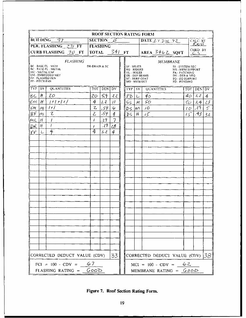
MCI and FCI Calculations
The MCI and FCI of a roof section are determined from the information recorded on the RoofInspection Worksheet. The calculations are completed on the Roof Section Rating Form (Figure 7) usingthe following procedure. A blank copy of the Roof Section Rating Form is provided in Appendix B.
Determine Deduct Values
Use information from the Roof Inspection Worksheet to complete the heading section of the RoofSection Rating Form. Transfer the quantities for each combination of distress type and severity level tothe Roof Section Rating Form. Flashing distresses are tabulated on the left side of the page andmembrane distresses on the right. Total the quantities for each severity of each distress, calculate eachdensity using the equations in Chapters 3 and 4, and determine deduct values (DV) from the Deduct ValueCurves in Appendix A.
17

ROOF INSPECTION WORKSHEET - COMMENTS
INSTRUCTIONS: Circle rosponse, i.e., Y = yes, N = no or U = unknown ornot observed. If Y (yes), circle the type of problem.
A. EVALUATION OF INTERIOR CONDITIONS
1. Does the roof leak? Describe: Ye N U
2. Are there water stains on: )N Ua. walls c. deck e. structural elements
@ ceilings d. floor f. other:
3. Do structural elements show any of the following: Y (D Ua. cracks d. alteration g. physical damageb. splits e. rotting h. insect damagec. spalling f. settlement i. other:
4. Does the underside of the deck show any of the following: Y Na. rusting c. spalling e. saggingb. rotting d. cracks f. other
B. EVALUATION OF EXTERIOR CONDITIONS
1. Do the exterior walls show any of the follwoing: Na. cracks c. spalling 0 water stainsb. rusting d. movement f. other:
2. Does the fascia or soffit show any of the following: Y 2a. cracks c. spalling e. water stainsb. rusting d. peeling f. other:
3. Do the gutters or downspouts show any of the following: Na. loose c. missing e. clogged( damaged d. disconnected f. other:
C. EVALUATION OF ROOFTOP CONDITIONS
1. Is there any unauthorized, unnecessary, or improperly Yinstalled equipment on the roof?a. equipment c. antennas e. cablesb. signs d. platforms f. other:
2. Do adjacent parapet walls show any of the following: Na. cracks c. cap cracked e. sealant flawsb. spalling @ cap missing f. other:
D. REMARKS:
Figure 6. Reverse Side of Roof Inspection Worksheet.
18
ROOF SECTION RATING FORM
BUILDING 97 SECTION _ _ DATE Z_-/ JLL /2 CALC. BYPER. FLASHING Z7/ FT" FLASHING K 6
CHKD. BYCURB FLASIIING 70 FT TOTAL 34/ FT" AREA - SQFT c.
FL4 SHING MEMBRANEBF BASE FL - MEM DR-DRAIN & SC SP - SPLITS SS - SYSTEM SECBC _ BASE FL - METAL RG - RIDGES MS - MEM SUPPORTMC METAL CAP HL - HOLES PA - PATCHINGEM - EMBEDDED MET DS - DEF SEAMS DV - DEB & VEGFP - FLASHIED PEN SC - SURF COAT EQ - EQ SUPPORTPP PITCH PAN MD- MEM DET PD - PONDING
TYP SV QUANTITIES TOT DEN DV TYP SV QUANTITIES TOT DENIDV
bc It zo Zo ,, b L. 40 4 , 4vi H 14H 1 t-l/ /,4 z 1; i ; H !o c /1,4 ý.3
Cm iol 1,7 Z. ? ,' rl /0 10 5 5i13F rk Z59 i D C,; H 1•- ~ 113 3e
a• tt / .z' z,r'ie. 4, 4 /.Z 4
CORRECTED DEDUCT VALUE (CDV) 33 CORRECTED DEDUCT VALUE (CDV) 38
FCI = 100 - CDV = _ _ MCI = 100 - CDV = _ _
FLASHING RATING = Gcob" MEMBRANE RATING = Go01>
Figure 7. Roof Section Rating Form.
19

Determine Corrected Deduct Values
Tabulate flashing deduct values in descending or(I.r as shown in Table 1. Determine the sums olflashing deduct values (XDV) and the number of distresses with deduct values greater than I (q), then usethese two values and the appropriate graph in Appendix A to determine corrected deduct values (CDV)for the flashing distresses. Circle the maximum value of CDV as shown in Table 1.
Repeat this process using the appropriate graph in Appendix A to determine the maximum correcteddeduct for the membrane.
Compute Membrane and Flashing Condition Indexes
Calculate flashing and membrane condition indexes using the following equations:
FCI = 100 - Max. CDVfasg
MCI = 100 - Max. CDVmembrae
Determine Membrane and Flashing Condition Ratings
Determine the corresponding descriptive condition ratings from Figure 1 for both indexes.
20

Table 1
Deduct Values in Descending Order
Flashing
(Distress data from the completed Roof Section Rating Form, Figure 7)
DV I')V q CDVnwhv
28 28 1 28
22 50 2 32
11 61 3 0
7 68 4 33
6 74 5 32
4 78 6 32
4 82 7 29
Maximum CDV.. = 33
Membrane
(Distress data from the completed Roof Section Rating Form, Figure 7)
DV IDV q CDV U,...
32 32 1 32
23 55 2
5 60 3 37
4 64 4 34
Maximum CDVnm_ = 38
21

3 FLASHING DISTRESSES
Index
Distress Page
Base Flashing - M embrane M aterial ............................................. 23
Base Flashing - Coated M etal ................................................. 28
Metal Cap Flashing . ........................................................ 31
Em bedded Edge M etal ...................................................... 35
Flashed Penetrations ........................................................ 39
P itch Panrs . . .. . . .. . . . . .. . . ... .. . . .. . .. . .. . . ... .. . ... . .. . . .. . .. .. . . . .. . .. . 42
Interior Drains and Roof Level Scuppers ......................................... 45
22
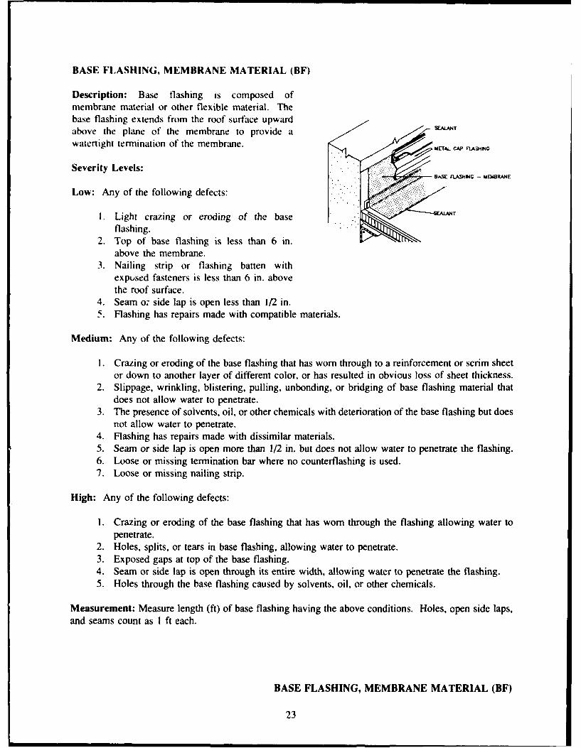
BASE FLASHING, MEMBRANE MATERIAL (BF)
Description: Base flashing is composed ofmembrane material or other flexible material. Thebase flashing extends from the roof surface upwardabove the plane of the membrane to provide a SEALMT
watertight termination of the membrane. METAL C
Severity Levels:
Low: Any of the following defects:
I. Light crazing or eroding of the base T
flashing.2. Top of base flashing is less than 6 in.
above the membrane.3. Nailing strip or flashing batten with
exposed fasteners is less than 6 in. abovethe roof surface.
4. Seam o; side lap is open less than 1/2 in.5. Flashing has repairs made with compatible materials.
Medium: Any of the following defects:
I. Crazing or eroding of the base flashing that has worn through to a reinforcement or scrim sheetor down to another layer of different color, or has resulted in obvious loss of sheet thickness.
2. Slippage, wrinkling, blistering, pulling, unbonding, or bridging of base flashing material thatdoes not allow water to penetrate.
3. The presence of solvents, oil, or other chemicals with deterioration of the base flashing but doesnot allow water to penetrate.
4. Flashing has repairs made with dissimilar materials.5. Seam or side lap is open more than 1/2 in. but does not allow water to penetrate the flashing.6. Loose or missing termination bar where no counterflashing is used.7. Loose or missing nailing strip.
High: Any of the following defects:
I. Crazing or eroding of the base flashing that has worn through the flashing allowing water topenetrate.
2. Holes, splits, or tears in base flashing, allowing water to penetrate.3. Exposed gaps at top of the base flashing.4. Seam or side lap is open through its entire width, allowing water to penetrate the flashing.5. Holes through the base flashing caused by solvents, oil, or other chemicals.
Measurement: Measure length (ft) of base flashing having the above conditions. Holes, open side laps,and seams count as I ft each.
BASE FLASHING, MEMBRANE MATERIAL (BF)
23

Density:
A x 100 = Problem DensityB
where A = length of base flashing defects (ft)B = total length of flashing on roof section being rated (including perimeter flashings and
flashings for penthouses, courtyards, and curbed projections).
Note: A problem density is calculated for each existing severity level.
Causes:
1. Flashing splits or tears can result from construction defects, mechanical damage, materialshrinkage, unattached membrane pulling the flashing, or differential movement between the walland the deck.
2. Slippage, wrinkling, or pulling of base flashing may result from weak or no attachment betweenthe flashing and the substrate. This can result from any of the following conditions:- adhesive or flashing material was improperly applied or substrate was not properly prepared,- adhesive used was improper type or poor quality, or- fasteners were improper or too few to hold flashing to the substrate.
BFL2 BFL3<Low Severity> <Low Severity>Top of base flashing is less than 6 in. above the Nailing strip with exposed fasteners is less thanmembrane 6 in. above the roof surface
BASE FLASHING, MEMBRANE MATERIAL (BF)
24

BFL4 BFMI<Low Severity> <Low Severity>Scam is open less than 1/2 in. Crazing or eroding of base flashing through to
another layer
BFM2 BFM2<Medium Severity> <Medium Severity>Wrinkling of base flashing Blistering of base flashing
BASE FLASHING, MEMBRANE MATERIAL (BF)
25

BFM5 BFM6<Medium Sevenity> <Medium Sevenity>Side lap is openl more than 112 in. but is not Loose termination har where no countertlashingallowing water to penctrate is used
BFH I BFH2<High Sevenity> <High Severity>Eroding of base flashing that allows water to Splits in the base flashingpenetrate
BASE FLASHING, MEMBRANE MATERIAL (BF)
26
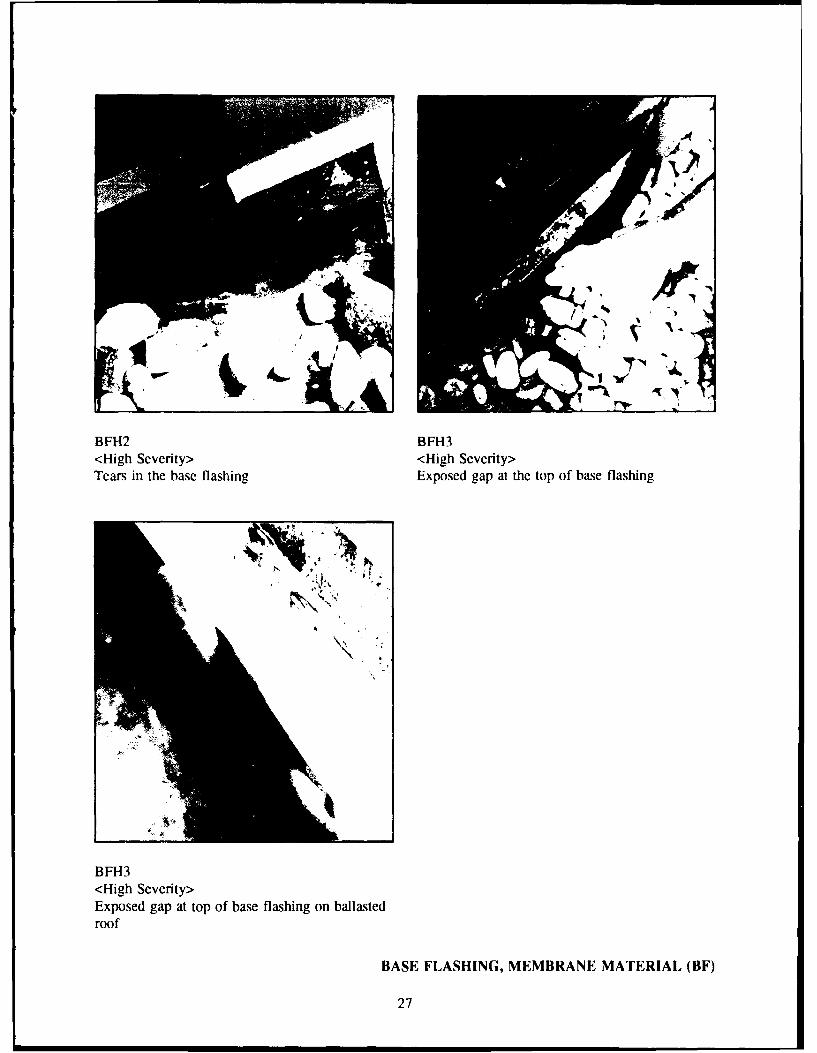
BFH2 BFH3<High Severity> <High Severity>Tears in the base flashing Exposed gap at the top of base flashing
BFH3<High Severity>Exposed gap at top of base flashing on ballastedroof
BASE FLASHING, MEMBRANE MATERIAL (BF)
27

BASE FLASHING, COATED METAL (BC)
Description: Base flashing material is composed ofmembrane-coated metal. The metal extends from theroof surface upwards above the plane of the mem-brane providing a watertight termination of themembrane.
,.T.. CAP RA&ING
Severity Levels:
Low: Any of the following defects:
I. Loss of protective coating or light corro-sion.
2. Distortion of joint covers.3. Top of flashing is less than 6 in. above the
roof surface.4. Exposed fasteners.
Medium: Any of the following defects:
1. Joint cover is unbonded to metal base flashing, but does not allow water to penetrate.2. Coated metal base flashing fasteners are loose.3. Coated metal base flashing has pulled away from the wall or curb or has lifted up but top
termination is watertight.4. Crazing or eroding of the joint cover material that has not worn through and does not allow
water to penetrate.5. Coated metal base flashing has repairs made with dissimilar materials.
High: Any of the following defects:
1. Holes in metal base flashing.2. Hole in joint cover or unbonding of joint cover from metal base flashing, allowing water to
penetrate.3. Exposed gaps at top termination of the base flashing.4. Coated metal base flashing has pulled away from the wall or curb or has lifted up, allowing
water to penetrate (rate full section of metal, normally a 10-ft length).
Measurement: Measure length (ft) of base flashing having the above conditions. Holes, open side laps,and seams count as 1 ft each. Each joint cover having a hole is counted as 1 ft. As a method of samplingthe joint covers for ballasted systems, determine the total number of existing joints by dividing the totallength of coated metal base flashing by the length of the metal sections (usually 10 ft). Every fourth jointshould be inspected for defects in the cover strip. Count the number of inspected joints having a specificdefect and multiply by 4 to determine the total length of the defect.
BASE FLASHING, COATED METAL (BC)
28

Density:A x 100 = Problem DensityB
where A = length of base flashing defects (ft)B = total length of flashing on roof section being rated (including perimeter flashings and
for penthouses, courtyards, and curbed projections).
Note: A problem density is calculated for each existing severity level.
BCL1 BCH2<Low Severity> <High Severity>Loss of protective coating Split in joint cover allowing water to penetrate
BASE FLASHING, COATED METAL (BC)
29
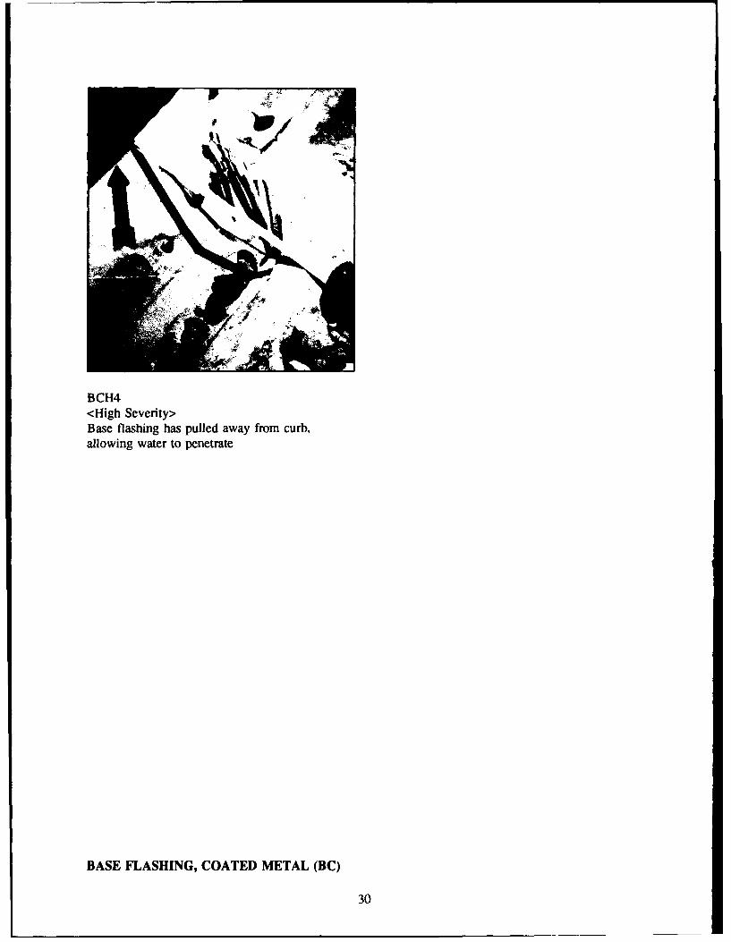
BCH4<High Severity>Base flashing has pulled away from curb,allowing water to penetrate
BASE FLASHING, COATED METAL (BC)
30

METAL CAP FLASHING (MC)
Description: Metal cap flashing includes any sheetmetal that serves to counterflash or cover a detailsuch as a parapet, firewall, roof area divider, equip-ment curb, raised roof edge, or an expansion joint,protecting the top termination of the base flashingand shedding water away from it. The metal capflashing should be free to expand and contract.
Note: Not all single plys are installed withcounterflashing to protect the top of the baseflashing. I SEALM,
Severity Levels:
Low: Any of the following defects:
1. Loss of protective coating or corrosionwithout holes.
2. Top of counterflashing or metal coping isdeformed and allows water to pond on the top.
3. Metal cap flashing is deformed but still performing its function.4. Metal cap flashing has been sealed to base flashing.
Medium: Any of the following defects:
1. Corrosion has caused holes in the metal on a sloping or vertical surface.2. Metal cap flashing has loose fasteners, failure of soldered or sealed joints, or loss of attachment.3. Metal cap flashing has rough edges that are in contact with base flashing.
High: Any of the following defects:
1. Metal cap flashing is missing or displaced from its original position.2. Corrosion has caused holes in the metal on a horizontal surface.3. Metal cap flashing has open joints or missing joint covers where covers were originally
installed.4. Sealant at reglet or top of counterflashing is missing or no longer functional, allowing water to
channel behind it.5. Counterflashing is loose at the top allowing water to channel behind it.6. Metal cap flashing does not extend over top of base flashing.
Measurement: Measure length (ft) of metal cap flashing having the above conditions. Individual defects(i.e., joints, holes) count as 1 ft minimum.
METAL CAP FLASHING (MC)
31
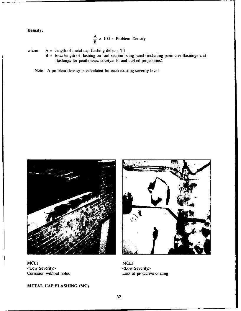
Density:AA x 100 = Problem Density
where A = length of metal cap flashing defects (ft)B = total length of flashing on roof section being rated (including perimeter flashings and
flashings for penthouses, courtyards, and curbed projections).
Note: A problem density is calculated for each existing severity level.
MCL1 MCLI<Low Severity> <Low Severity>Corrosion without holes Loss of protective coating
METAL CAP FLASHING (MC)
32

I,?
MCL3 MCM2<Low Severity> <Medium Severity>Metal cap flashing is deformed Metal cap flashing has loose fasteners
MCM3 MCH2<Medium Severity> <High Severity>Metal cap flashing has rough edges that are in Corrosion holes have occurred through the metalcontact with the base flashing on a horizontal surface
METAL CAP FLASHING (MC)
33

MCH3<High Severity>Metal cap flashing has missing joint cover
METAL CAP FLASHING (MC)
34

EMBEDDED EDGE METAL (EM)
S1RPP -IN SYS11E COATED METATL SYSTEld
• lMEMBR~ANE WEDE TO
COATED METAL
COATED METAL
•-CONI~UO.S CL.EAT •-CON'INUOUS U.,..AT
Description: Embedded edge metal is a formed strip of metal at the edge of the roof that continues downthe vertical part of the wall to form a fascia or drip edge. This stripped-in flashing provides a finishedtermination for the roofing membrane. On all but coated-metal flashing systems, the metal is placed ontop of the membrane and fastened to the deck through it. To make that area watertight, the metal iscovered with membrane or flashing material (i.e., it is stripped in). Coated metal systems have their edgemetal placed before the membrane. The membrane is adhered to the top of the coated metal, therebyeliminating the need to have it stripped in. A formed vertical projection (gravel stop) may be incorporatedto prevent ballast from rolling or washing off the roof. Exterior and interior gutters, which are embeddedin the membrane, are considered embedded edge metal. (An interior gutter is a built-in trough of metalor other material that collects water from the roof and carries it to a drain or downspout.)
Severity Levels:
Low: Any of the following defects:
1. Loss of protective coating or light corrosion.2. Termination battens have exposed fasteners.3. Stripping material is open less than 1/2 in.4. Distortion of joint covers.5. For coated metal edge flashings that are not stripped in, membrane is open less than 1/2 in.
Medium: Any of the following defects:
1. Joint cover is unbonded to embedded edge metal, but does not allow water to penetrate.2. Nails under stripping material are backing out.3. Stripping material is crazing, checked, or cracked.4. Stripping material is open more than 1/2 in., but edge metal fasteners are not exposed.5. Loose or lifted metal with deterioration of the stripping material.
EMBEDDED EDGE METAL (EM)
35

6. Embrittled joint stripping material.7. The entire length of interior gutter is rated medium as a minimum due to the potential for leak
damage.8. For coated metal edge flashings that are not stripped in, membrane is open more than 1/2 in.
but does not allow water to penetrate.
High: Any of the following defects:
I. The stripping material is missing or open and edge metal fasteners are exposed, or strippingmaterial has holes, cuts or tears, allowing water to penetrate.
2. Hole in joint cover or unbonding of joint cover from embedded edge metal, allowing water topenetrate.
3. Holes through the metal.4. Holes associated with loose or lifted embedded edge metal.5. Holes in the interior gutter.6. For coated metal edge flashings that are not stripped in, membrane is open allowing water to
penetrate.
Measurement: Each split above a joint is counted as 1 ft. As a method of sampling the embedded edgemetal joints for ballasted systems, determine the number of joints by dividing the total length of embeddededge metal flashing by the length of the edge metal sections (often 10 ft). Gravel should be moved atevery fourth joint and the stripping material inspected for splits. Count the number of inspected jointshaving a specific defect and multiply by four to deterntine the total length of the defect.
Density:A x 100 = Problem DensityB
where A = length of embedded edge metal flashing defects (ft)B = total length of flashing on roof section being rated (including perimeter flashings and
flashings for penthouses, courtyards, and curbed projections).
Note: A problem density is calculated for each existing severity level.
Causes:
1. Splits in the stripping material and loose stripping material are caused by:- insufficient or improper nailing of the metal, allowing it to move,- insufficient bonding of the stripping material to the embedded metal, or- embrittlement or hardening of stripping material.
2. Exposed metal flanges can result from stripping material deterioration or the flange may havenever been stripped-in.
3. Loose or lifted metal edge is caused by insufficient fasteninp, rotting or lack of a woodperimeter nailer, membrane shrinkage, or high winds.
EMBEDDED EDGE METAL (EM)
36

EML4 EMM7<Low Severity> <Medium Severity>Distortion of joint cover Interior gutter
EMH I EMHI<High Severity> <High Severity>Stripping material is open Stripping material is tom
EMBEDDED EDGE METAL (EM)
37

EMH2<High Severity>Hole in joint cover
EMBEDDED EDGE METAL (EM)
38

FLASHED PENETRATIONS (FP)
PWYEFABMjCAU SY'18d AM ASDLED SYS1nN
PREFAMCED SOT f.ASHNO aimMEWBRANE MAYMAI.
SEALANTSELN
Description: This category includes pipes, plumbing vent stacks, flues, ducts, conduits, guy wires, drainsumps, and other penetrations through the roof membrane (excluding pitch pans but including metal curb-ing for hatches and ventilators, where the metal flange is stripped into the membrane or, in the case ofsome coated metal flashing systems, the membrane is adhered to the top of the coated metal flange,thereby eliminating the need to have it stripped in).
Severity Levels:
Low: Any of the following defects:
1. Flashing sleeve is deformed.2. Stripping material, boot, or membrane (for coated metal flashing sleeves) is open less than
1/2 in.3. Top of flashing is less than 6 in. above the membrane.
Medium: Any of the following defects:
1. Stripping material is crazing, checked, or cracked.2. Stripping material, boot, or membrane (for coated metal flashing sleeves) is open more than
1/2 in. but does not allow water to penetrate the flashing.3. Top of flashing sleeve or boot is not sealed or is not rolled down into the existing plumbing
vent stack.4. Clamping band is loose or missing (where required).5. Umbrella is open or no umbrella is present (where required).6. Corrosion of metal or delamination of coating.
High: Any of the following defects:
1. Stripping material has holes, cuts, or tears.2. Stripping material, boot, or membrane (for coated metal flashing sleeves) is open, allowing
water to penetrate.
FLASHED PENETRATIONS (FP)
39

3. Holes, cuts, or tears in flashing sleeve or metal curb.4. No flashing sleeve present.5. Incompatible flashing material has been used.
Measurement: Count each small distressed flashed penetration as 1 ft at the highest severity level present.For metal curbs and ducts with more than 1 ft of perimeter, measure the length (in ft) of the distressedperimeter.
Density:A x 100 = Problem DensityB
where A = length of distressed flashed penetrations (ft)B = total length of flashing on roof section being rated (including perimeter flashings and
flashings for penthouses, courtyards, and curbed projections).
Note: A problem density is calculated for each existing severity level.
FPL2 FPL3<Low Severity> <Low Severity>Stripping material is open less than 1/2 in. Top of flashing is less than 6 in. above the
ballasted roof surface
FLASHED PENETRATIONS (FP)
40

FPL3 FPH2<Low Severity> <High Severity>Top of flashing is less than 6 in. above the Stripping material is openmembrane
FPH4<High Severity>No flashing sleeve present
FLASHED PENETRATIONS (FP)
41

PITCH PANS (PP)
COATED MTAL SYSIIIlS %MpPW -.4N SS1B4
SUDFLL SLOPD RLLSCOATED MELTAL DAM4 METAL DAM
MEMtBRANE W4ELDED TO STIPN 1MTRA
META FLSNO
Description: A pitch pan is a flanged metal sleeve piaceu around a roof-penetration element and tuieuwith a sealer. For pitch pans on ethylene-propylene-diene monomer (EPDM) and Hypalon roofing sys-tems, stripping material should cover the sides of the metal pan and terminate within the pan below thesealer.
Severity Levels:
Low:
t. All pitch pans are low severity at a minimum due to the maintenance requirements.
Medium: Any of the following defects:
1. Stripping material is crazing, checked, or cracked.2. Stripping material or membrane (on coated metal pitch pans) is open more than 1/2 in. but does
not allow water to penetrate the flashing.3. Loss of protective coating or corrosion of metal.4. For EPDM and Hypalon, stripping material is not covering the top of the metal pan or does not
terminate below the sealer.
High: Any of the following defects:
1. Stripping material has holes, cuts, or tears, allowing water to penetrate through.2. Edge of stripping material or membrane (on coated metal pitch pans) is open, allowing water
to penetrate.3. Sealer is below the metal rim, allowing ponding in the pan.4. Sealer has cracked or separated from the pan or penetration.5. Corrosion through the metal pan.
PITCH PANS (PP)
42

Measurement: Each distressed pitch pan should be counted once at the highest severity level present.
Density:
A x 100 = Problem DensityB
where A = number of distressed pitch pans (ea)B = total length of flashing on roof section being rated (including perimeter flashings and
flashings for penthouses, courtyards, and curbed projections).
Note: A problem density is calculated for each existing severity level.
PPL 1 PPM3<Low Severity> <Mediumn Severity>Pitch pan installed and maintained correctly Loss of protective coating
PITCH PANS (PP)
43

PPM4 PPH-3<Metdiumn Severity> <High Severity>Stripping material is not covering metal pan onl Scaler is below metal riman EPDM system
PITCH PANS (PP)
44

INTERIOR DRAINS AND ROOF LEVEL SCUPPERS (DR)
Description: A drain is a penetration of the roofmembrane that allows water to flow into a pipeddrainage system. The drain fixture at the roof has aflange and/or clamping arrangement to which the MOMMMroofing membrane is attached. Stripping materialmay also be present at the drain. A scupper is achannel through a parapet or raised roof edge that isdesigned to drain the roof. Roof-level scuppers arefor primary drainage. Elevated (overflow) scuppersare for emergency drainage. I"'-- &W
Note: Most single-ply roofing systems do not re-
quire stripping material around the drain.
Severity Levels:
Low: Any of the following defects:
1. Field seam within 1 ft of a drain or roof-level scupper.2. Stripping material or membrane is open less than 1/2 in.
Medium: Any of the following defects:
I. Stripping material is crazing, checked, or cracked.2. Stripping material or membrane is open 1/2 in. or more, but does not allow water to penetrate.3. Strainer is broken or missing.SScupper shows loss of protective coating or start of metal corrosion.5. Drain has a field seam in the clamping ring.
High: Any of the following defects:
I. Stripping material has holes, cuts, or tears, allowing water to penetrate.2. Stripping material or membrane is open, allowing water to penetrate.3. Clamping ring is loose or missing from drain or bolts are missing.4. Drain is clogged.5. Scupper is broken or contains holes.6. Holes, cuts, tears, or abrasions through the membrane within 2 ft of the drain or scupper.
Measurement: Each distressed drain and scupper should be counted once at the highest severity levelpresent.
INTERIOR DRAINS AND ROOF LEVEL SCUPPERS (DR)
45
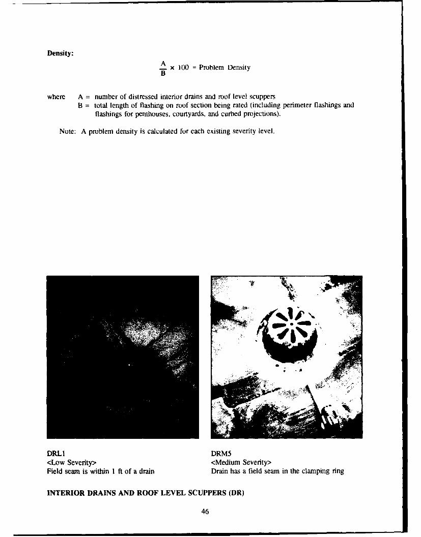
Density:ASx 100 = Problem Density
where A = number of distressed interior drains and roof level scuppersB = total length of flashing on roof section being rated (including perimeter flashings and
flashings for penthouses, courtyards, and curbed projections).
Note: A problem density is calculated for each existing severity level.
41-
DRLI DRM5<Low Severity> <Medium Severity>Field seam is within 1 ft of a drain Drain has a field seam in the clamping ring
INTERIOR DRAINS AND ROOF LEVEL SCUPPERS (DR)
46

<High Severity> <High Sevenity>Membrane is not clamped, allowing water to Clamping ring is brokenpenetrate
' SM
DRH3 DRH4<High Severity> <High Severity>Bolts are missing from clamping ring Drain is clogged
INTERIOR DRAINS AND) ROOF LEVEL SCUPPERS (DR)
47
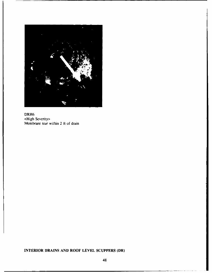
DRH6<High Severity>Membrane tear within 2 ft of drain
INTERIOR DRAINS AND ROOF LEVEL SCUPPERS (DR)
48

4 MEMBRANE DISTRESSES
Index
Distress Page
S p lits . . . . . . . . . . . . . . . . . . . . . . . . . . . . . . . . . . . . . . . . . . . . . . . . . . . . . . . . . . . . . . . . . . 50
R idges . . . . . . . . . . . . . . . . . . . . . . . . . . . . . . . . . . . . . . . . . . . . . . . . . . . . . . . . . . . . . . . . . 52
Holes, Cuts, and Abrasions ................................................... 54
Defective Seam s .......................................................... 57
Surface Coating Deterioration ................................................. 61
M em brane Deterioration ..................................................... 63
System Securement Deficiencies ............................................... 65
Membrane Support Deficiencies ............................................... 69
Patching ..... ......... ............................ ........... ......... .. 7 1
Debris and Vegetation ...................................................... 73
Improper Equipment Supports ................................................. 76
Ponding .. .. .................. ....... ................. ........... ....... 78
49

SPLITS (SP)
Description: Splits are cracks or tears that extend through the membrane. They vary in length from afew inches to the length of the roof and in wiJth from hair-line to more than I .a.
Note: Cuts are rated as Holes, Cuts, and Abrasions ('HL) distresses.
Severity Levels:
High:
1. All splits in the membrane are considered high severity due to their leak potential.
Measurement: Measure length of split.
Density:AA x 100 = Problem Density
where A = total length of membrane splits (ft)
B = total area of roof section being rated (sq ft).
Causes:
1. Membrane shrinkage or embrittlement.2. Movement of the substrate.3. Warping of insulation boards.4. Thermal contraction of the membrane.
SPLITS (SP)
50

- z4 -J 0, w
r"r
SPH I SPH I<High Severity> <High Severity>Membrane split Membrane split on ballasted roof
SPLITS (SP)
51

RIDGES (RG)
Description: Ridges are long, narrow (usually less than 3 in.). raised portions of the roof membrane.Usually ridges occur directly above the insulation board joints.
Note: Wrinkles in the membrane are no[ rated as ridges. Wrinkles that block drainage and causeponding are rated as Ponding (PD). Wrinkles occurring on fully-adhered systems are ratedas System Securement Deficiencies (SS).
Severity Levels:
Low:
1. All ridges are rated low severity as a minimum.
High:
1. Open breaks have developed in the ridge allowing water to penetrate.
Measurement: Measure length of ridges running in all directions. When many ridges are present, therepresentative sampling technique may be used.
Density:
A x 100 = Problem DensityB
where A = total length of membrane ridges (ft)B = total area of roof section being rated (sq ft).
Note: A problem density is calculated for each existing severity level.
Causes: Ridging can result from internally generated moisture collecting at insulation joints and affectingthe membrane or from movement of the substrate.
RIDGES (RG)
52

AW
RGL 1 RGH1<Low Severity> <High Severity>Watertight ridges having no open breaks Open breaks have developed in the ridge
RIDGES (RG)
53

HOLES, CUTS, AND ABRASIONS (HL)
Description: Holes and cuts are membrane distresses caused by physical abuse from tools, traffic, debris,gravel, wind, etc., or manufacturing defects such as pinholes. Holes and cuts can be of various shapesand sizes. Abrasion is physical damage that has roughened or worn the membrane surface.
Severity Levels:
Low:
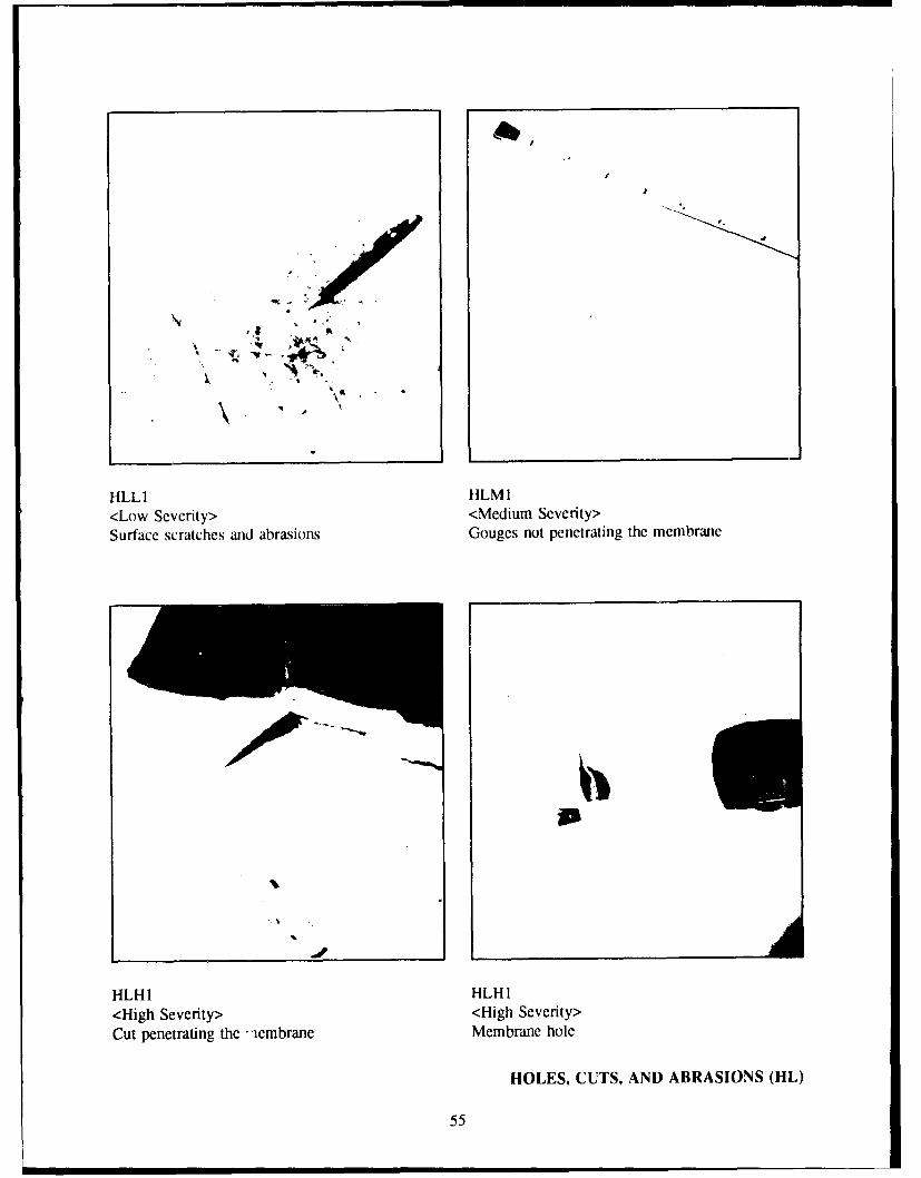
1. Surface scratches or abrasions with no significant loss of membrane thickness.
Medium:
i. Cuts, gouges, or abrasions with loss of membrane thickness but not fully penetrating themembrane.
High: Any of the following defects:
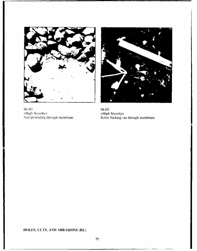
1. Holes, cuts, gouges, or abrasions that penetrate the membrane.2. Holes through the membrane caused by underlying mechanical fasteners.
Measurement:
1. Count the total number of scratches, gouges, holes, and cuts in the membrane. If the dista,,cebetween distresses is less than 1 ft, count the distresses as one. If the distress is longer than Ift, measure the length. Measure area of abrasion in square feet.
2. When large quantities of this problem are present, the representative sampling technique maybe used.
Density:AA x 100 = Problem Density
where A = total number and/or length of membrane scratches, gouges, holes and cuts (ft) or total areaof abrasion (sq ft)
B = total area of roof section being rated (sq ft).
Note: A problem density is calculated for each existing severity level.
Causes:
1 Roof traffic.2. Debris.3. Broken or sharp ballast, especially at wrinkled areas.4. Manufacturing defects such as pinholes.5. Mechanical fasteners.6. Wind-borne objects.
HOLES, CUTS, AND ABRASIONS (HL)
54
HLH HL I
I
I
FILL 1 HLMI1<Low Scverity> <Medium Severity>Surface scratches and abrasions Gouges nlot penetrating the membrane
p
ILHI 1 HLH I
<High Severity> <High Severity>Cut penetrating the .aembrane Membrane hole
HOLES, CUTS, AND ABRASIONS (HL)
55
I -
HL12 HLH2<Hligh Severity> <High Severity>Nail protruding through membrane Screw backing out through membrane
HOLES. CUTS, AND ABRASIONS (HL)
56
DEFECTIVE SEAMS (DS)
Description: Defective seams include incomplete, damaged, or weak seams that join two sheets of amembrane.
Note: For EPDM and polyvinyl chloride (PVC) membranes, all field seams should have lapsealant at the edges. All other membranes should have lap sealant at cut edges of seamsthat have exposed reinforcement material.
Severity Levels:
Low: Any of the following defects:
1. Missing lap sealant at field seam (EPDM and PVC membranes only).2. Missing lap sealant at field seam which has exposed reinforcement material at seam edge
(usually at end laps and field-cut edges of sheets).3. Seam is open less than 1/2 in.4. Wrinkling at seam that is watertight.5. Seam intersections (e.g., T-joints) on EPDM that do not have a patch covering them.6. Blisters within the seam.
Medium: Any of the following defects:
1. Seam is open 1/2 in. or more, but does not allow water to penetrate the membrane.2. Pinch wrinkle at seam.
High: Any of the following defects:
1. Seam is open through its entire depth, allowing water to penetrate.2. Fishmouths, wrinkles, or bunches at the seam that allow water to penetrate.
Measurement: For exposed membranes (no overlying ballast), inspect all seams visually.
For ballasted roofs, check field seams at five different locations on the roof section. Clear ballastfrom 5 ft of the seam at each location then clean the exposed seam with a whisk broom. If all checkedseams are without defects, assume the remaining field seams are satisfactory. If any defects are found,use the following sampling technique:
I. For roof sections with sheet widths of 10 ft or less, inspect 2 percent of the total length of fieldseams (2 ft every 100 ft of seam). For roof sections having sheet widths greater than 10 ft,inspect 4 percent of the total length of field seams (2 ft every 50 ft of seam). Measure lengthof each specific seam defect found.
2. Extrapolate to determine the total length of seam defects for the entire roof section from thetotal length of defect found. When 2 percent of the seams are inspected, multiply the actualdefect length by 50 to compute total length of defect. When 4 percent of the seams areinspected, multiply actual defect length by 25 to compute total length of defect.
DEFECTIVE SEAMS (DS)
57

Density:A x 100 = Problem DensityB
where A = total length of defective seams (ft)B = total area of roof section being rated (sq ft).
Note: A problem density is calculated for each existing severity level.
Causes:
1. Seams improperly made.2. Seams damaged in use.3. Wrinkles in the membrane at the seam.
DSL1 DSL2<Low Severity> <Low Severity>Missing lap sealant Missing lap sealant with exposed reinforcement
material
DEFECTIVE SEAMS (DS)
58
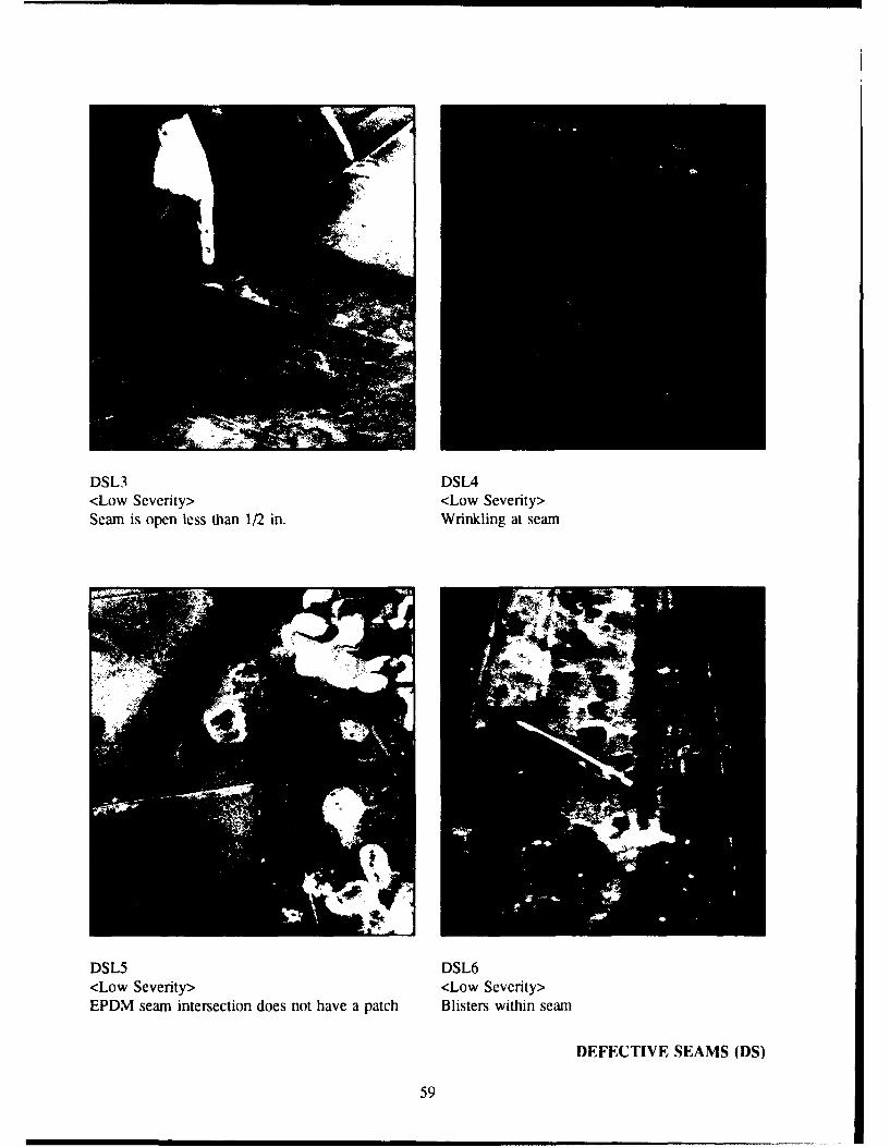
DSL3 DSL4<Low Severity> <Low Severity>Seam is open less than 1/2 in. Wrinkling at seam
DSL5 DSL6<Low Severity> <Low Severity>EPDM seam intersection does not have a patch Blisters within seam
DEFECTIVE SEAMS (DS)
59

Ak
DSM I DSM2<MNediumi Severity> <Medium Sevenity>Seam is open more than 1/2 in. Pinch wrinkle at the seam
DSH I<High Severity>Seam is open through its entire depth
DEFECTIVE SEAMS (DS)
60
SURFACE COATING DETERIORATION (SC)
Description: Surface coating deterioration includes wear, blistering, or peeling of any surface coatingapplied for fire protection (such as adhesive coating and sand on an EPDM membrane) or solarreflectivity, but not waterproofing.
Severity Levels:
Low:
1. Color of underlying membrane can be seen through the coating or membrane has lost coatingprotection (for membrane with coating protection that does not have sand or mineral matterembedded).
Medium:
I. Membrane area has lost the sand or mineral matter portion of the coating protection (formembrane with coating protection that has sand or mineral matter embedded).
Measurement:
1. Measure the square feet of each affected area and rate at the highest severity level present.2. When large quantities of this problem are present, the representative sampling technique may
be used.
Density:ASx 100 = Problem DensityT
where A = total area of surface coating deterioration (sq ft).
B = total area of roof section being rated (sq ft).
Note: A problem density is calculated for each existing severity level.
Causes:
1. Weathering.2. Roof traffic.3. Poor adherence of coating to membrane due to material or application problems.
SURFACE COATING DETERIORATION (SC)
61

SCL 1 SCM I
<Low Severity> <Medium Severity>Loss of protective coating Loss of protective sand coating
SURFACE COATING DETERIORATION (SC)
62

MEMBRANE DETERIORATION (MD)
Description: This category includes erosion or crazing of the membrane. Erosion is the wearing awayof the membrane surface creating a rough texture. Crazing is hairline cracking of the membrane.
Severity Levels:
Low:
1. Light crazing of the membrane surface.
Medium:
1. Crazing or eroding of the membrane surface that has worn through to a reinforcement or scrimsheet or down to another layer of different color, or has resulted in obvious loss of sheetthickness.
High:
1. Crazing or eroding of the membrane surface that has worn through the membrane allowingwater to penetrate.
Measurement:
I. Measure the square feet of each affected area and rate at the highest severity level present.2. When large quantities of this problem are present, the representative sampling technique may
be used.
Density:ASx 100 = Problem DensityB
where A = total area of the membrane deterioration (sq ft)B = total area of roof section being rated (sq ft).
Note: A problem density is calculated for each existing severity level.
MEMBRANE DETERIORATION (MD)
63

MDLI MDLI<Low Severity> <Low Severity>I ight crazing of mnembrane surflace Light crazing of membrane shown bý -olor
change
;No-.-.-.-. .
-rdngo mebae wt exoedscri Sci cmlteyexoe
MEMBRANEa DEERIORATION (MD)
o 0 0 C 0 * S 0 S s64
SYSTEM SECUREMENT DEFICIENCIES (SS)
Description: For fully adhered membranes, system securement deficiencies include membrane areas(including blisters) that are unattached to the substrate. For mechanically attached membranes, thiscategory includes failed mechanical fasteners. For partially adhered membranes, the category includesmembrane that is not adhered at points of attachment. For ballasted membranes, the membrane has areaswhere ballast is missing or displaced.
Note: Holes in the membrane caused by mechanical fasteners are rated as Holes (HL).Note: If ballast is redistributed by the inspector to cover bare areas, these areas should not be
counted as defects.Note: For defect definitions, "building perimeter" is the area within 10 ft of a roof edge. These
areas experience high wind uplift pressures.
Severity Levels:
Low: Any of the following defects:
1. For fully adhered systems, an area of unattached membrane or substrate of 2 sq ft or less.2. For ballasted systems, a bare area of 4 sq ft or less.
Medium: Any of the following defects:
1. For fully adhered systems, an area of unattached membrane or substrate of greater than 2 sq ftbut less than 100 sq ft (less than 25 sq ft at building perimeter).
2. For mechanically attached systems, an isolated mechanical fastener that has lost its attachmentcapability or backed out causing bridging of the membrane.
3. For partially adhered systems, an isolated point of attachment that has lost adherence.4. For ballasted systems, a bare area of greater than 4 but less than 100 sq ft (less than 25 sq ft
at building perimeter).
High: Any of the following defects:
1. For fully adhered systems, an area of unattached membrane or substrate 100 sq ft or greater (25sq ft at building perimeter).
2. For mechanically attached systems, adjacent mechanical fasteners that have lost their attachmentcapability or backed out causing bridging of the membrane.
3. For partially adhered systems, adjacent points of attachment that have lost adherence.4. For ballasted systems, a bare area of 100 sq ft or greater (25 sq ft at building perimeter).
Measurement:
1. Measure square feet of membrane having the above conditions. For mechanically fastened andpartially adhered systems, count the effective area of unattached membrane.
2. When large quantities of this problem are present, the representative sampling technique maybe used.
SYSTEM SECUREMENT DEFICIENCIES (SS)
65

Density:
Ax 100 = Problem Density
where A = total area of attachment defects (sq ft)B = total area of roof section being rated (sq ft).
Note: A problem density is calculated for each existing severity level.
Causes:
1. Overdriven, underdriven, or crooked placement of fasteners.2. Membrane was adhcred before the solvent had flashed off from the contact adhesive.3. Wind damage.4. Traffic damage.5. Moisture within the system.
~ire
- ~ ~ ~ ~ W -:00,~f -
1' 6
SSL I SSL2<Low Severity> <Low Severity>Unattached membrane of less than 2 sq ft Ballasted system. bare area of less than 4 sq ft
SYSTEM SECUREMENT DEFICIENCIES (SS)
66
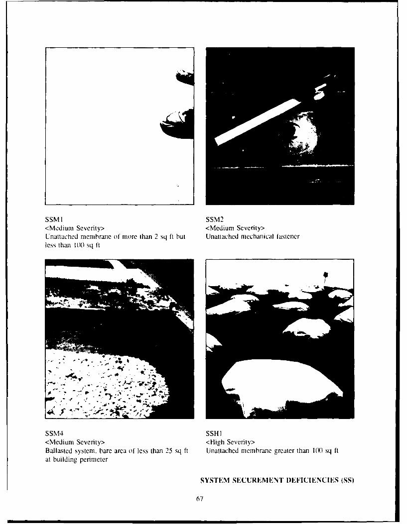
SSMI SSM2<Medium Severity> <Medium Severity>Unattached membrane of more than 2 sq ft but Unattached mechanical fastenerless than 100 sq ft
&/
lw.~ ~ ,-, .: - .. . - .
SSM4 SSH 1<Medium Severity> <High Severity>Ballasted system, bare area of less than 25 sq ft Unattached membrane greater than 1X) sq ftat building perimeter
SYSTEM SECUREMENT DEFICIENCIES (SS)
67

--- ~4 Io• "
SS H2 SSH4<High Severity> <High Severity>Adjacent mechanical fasteners have lost their Ballasted system, bare area more than 1 )0 sq ftattachment capability
SYSTEM SECUREMENT I)EFICIENCIES (SS)
68
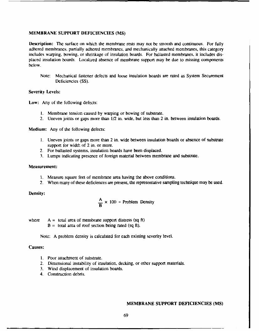
MEMBRANE SUPPORT DEFICIENCIES (MS)
Description: The surface on which the membrane rests may not be smooth and continuous. For fullyadhered membranes, partially adhered membranes, and mechanically attached membranes, this categoryincludes warping, bowing, or shrinkage of insulation boards. For ballasted membranes, it includes dis-placed insulation boards. Localized absence of membrane support may be due to missing componentsbelow.
Note: Mechanical fastener defects and loose insulation boards are rated as System SecurementDeficiencies (SS).
Severity Levels:
Low: Any of the following defects:
1. Membrane tension caused by warping or bowing of substrate.2. Uneven joints or gaps more than 1/2 in. wide, but less than 2 in. between insulation boards.
Medium: Any of the following defects:
1. Uneven joints or gaps more than 2 in. wide between insulation boards or absence of substratesupport for width of 2 in. or more.
2. For ballasted systems, insulation boards have been displaced.3. Lumps indicating presence of foreign material between membrane and substrate.
Measurement:
1. Measure square feet of membrane area having the above conditions.2. When many of these deficiences are present, the representative sampling technique may be used.
Density:A x 100 = Problem DensityB
where A = total area of membrane support distress (sq ft)
B = total area of roof section being rated (sq ft).
Note: A problem density is calculated for each existing severity level.
Causes:
I. Poor attachment of substrate.2. Dimensional instability of insulation, decking, or other support materials.3. Wind displacement of insulation boards.4. Construction debris.
MEMBRANE SUPPORT DEFICIENCIES (MS)
69

NISL1 MSMI<Low Severity> <Medium Severity>Membranc tension caused by warping or bowing Uneven support more than 2 in, wideof the substrate
MSM2 MS NI3<Medium Severity> <Medium Severity>Insulation boards have been displaced Lumps indicating foreign material
MEMBRANE SUPPORT DEFICIENCIES (MS)
70

PATCHING (PA)
Description: Patching is a localized temporary or permanent repair of the membrane using dissimilarmaterials. Repairs made with similar materials are not counted as patches; distresses associated with theserepairs should be recorded in the appropriate category (often defective seams) and not as patchingdistresses.
Severity Levels:
Low:
1. All patches that are not made with similar materials as that of the original construction are ratedas low severity as a minimum.
Medium:
1. All patches made with temporary materials (i.e., duct tape. caulkings, and sealants) are ratedmedium severity as a minimum.
High:
1. Other distresses of high severity are present within the patched area (count as patching distressonly).
Measurement:
1. Measure square feet of each patch having the above conditions.2. When large quantities of this problem are present, the representative sampling technique may
be used.
Density:ASx 100 = Problem Density
where A = total area of patching (sq ft)B = total area of roof section being rated (sq ft).
Note: A problem density is calculated for each existing severity level.
PATCHING (PA)
71
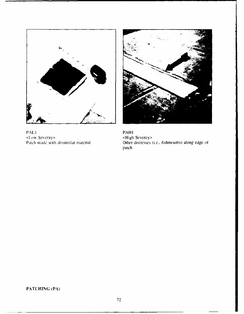
PAL I PAH I<LowA Severitv> <High Severity>Patch made with dissimilar material Other distresses (i.e.. fishniouths) alonlg edge of
patch
PATCHING (PA)
72
DEBRIS AND VEGETATION (DV)
Description: Debris and vegetation includes the presence of foreign objects, vegetation, fungal growth,solvents, oils, or other chemicals that could damage, puncture, or degrade the membrane.
Note: Accumulation of oils and grease can present a significant fire hazard and should be reportedimmediately.
Note: Do not rip out vegetation that is growing into the waterproofing system, as that may allowwater to penetrate.
Severity Levels:
Medium: Any of the following defects:
I. Vegetation that has not penetrated the membrane.2. Degradation of the membrane caused by solvents, oil, or other chemicals.3. Foreign materials that are not removed from the roof during the inspection.
High: Any of the following defects:
1. Vegetation that has penetrated the membrane.2. Degradation of the membrane caused by solvents, oil, or other chemicals allowing water to
penetrate.
Measurement: Measure square feet of debris and vegetation having the above conditions.
Density:A x 100 = Problem DensityB
where A = total area of debris and vegetation (sq ft)B = total area of roof section being rated (sq ft).
Note: A problem density is calculated for each existing severity level.
Causes: Lack of preventative maintenance.
DEBRIS AND VEGETATION (DV)
73

DV\I IDVM%2<MIedium Severity> <Meldiumi Severity'>Vegetation that has~ not penctrated the mcmhrance Degradation ol membrane caused by solvents or
oil
DVNI DVH I<Medlium Severitv> <Hligh Se%,erity>Foreign materials that were not removed dlurnng Veoctation that has penetrated the mcnmbraneinspectlion
DEBRIS AN) VEGETATION (DV)
74
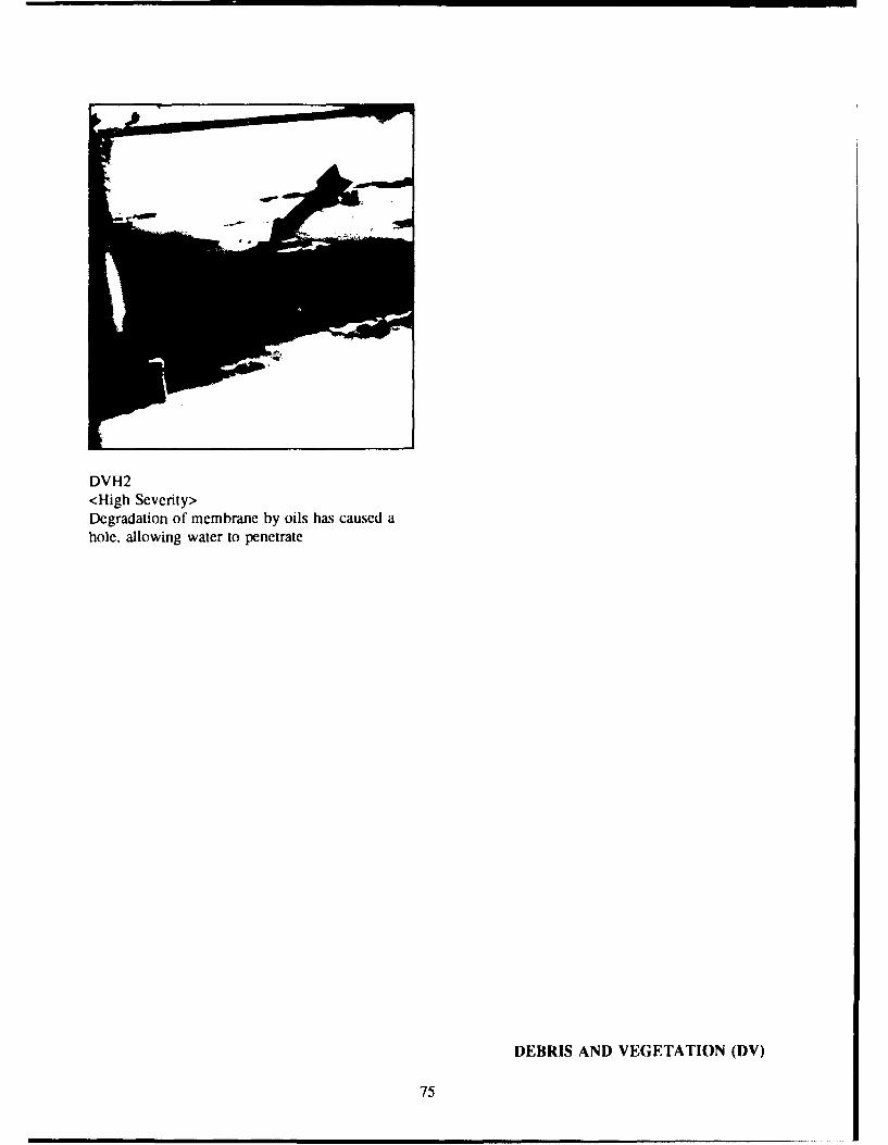
DVH2<High Severity>Degradation of membrane by oils has caused ahole. allowing water to penetrate
DEBRIS AND VEGETATION (DV)
75

IMPROPER EQUIPMENT SUPPORTS (EQ)
Description: Improper equipment supports or pipes, conduits, and mechanical equipment supports (woodsleepers, channels, etc.) that are placed directly on the membrane with no protective pad or are not placedhigh enough to allow for maintenance of the membrane below the equipment. Repairing this distress mayrequire replacing the surrounding insulation and membrane.
Note: Terminations for guy wires are rated as Flashed Penetration (FP) distresses.
Severity Levels:
Low:
1. All improper equipment supports are rated low severity as a minimum due to the maintenanceproblems associated with them.
Medium: Any of the following defects:
I. Movement of the support has displaced the membrane but has not cut or punctured it.2. Equipment is bolted through the membrane but the membrane is sealed and watertight.
High: Any of the following defects:
1. Movement of support has cut or punctured the roof membrane.2. The equipment is bolted through the membrane and the membrane is not sealed, allowing water
to penetrate.
Measurement: Measure square feet of each improper equipment support. The minimum dimensions forlength and width of a support shall be 1 ft.
Density:
A x 100 = Problem DensityB
where A = total area of improper equipment supports (sq ft)B = total area of roof section being rated (sq ft).
Note: A problem density is calculated for each existing severity level.
Causes:
I. Inadequate design.2. Poor construction.
IMPROPER EQUIPMENT SUPPORTS (EQ)
76

EQL I EQL I<Low Severity> <Low Severity>Equipment stand supported by wood blocking Pipe supported by wood blocks
EQL I EQH Il<Low Severity> <High Severity>improper equipment supports Movement of support has cut the membrane
IMPROPER EQUIPMENT SUP'PORTS (EQ)
77
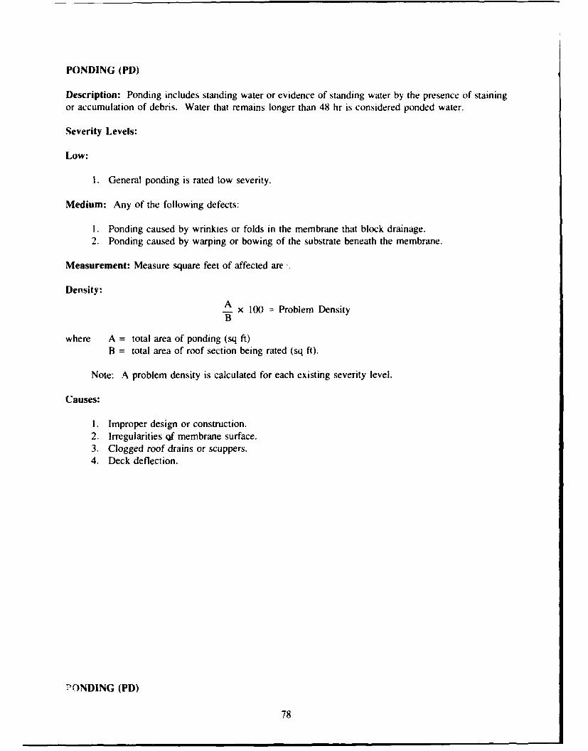
PONDING (PD)
Description: Ponding includes standing water or evidence of standing water by the presence of stainingor accumulation of debris. Water that remains longer than 48 hr is considered ponded water.
Severity Levels:
Low:
I. General ponding is rated low severity.
Medium: Any of the following defects:
1. Ponding caused by wrinkies or folds in the membrane that block drainage.2. Ponding caused by warping or bowing of the substrate beneath the membrane.
Measurement: Measure square feet of affected are,.
Density:A x 100 = Problem DensityB
where A = total area of ponding (sq ft)B = total area of roof section being rated (sq ft).
Note: A problem density is calculated for each existing severity level.
Causes:
1. Improper design or construction.2. Irregularities Qf membrane surface.3. Clogged roof drains or scuppers.4. Deck deflection.
PONDING (PD)
78

*D I.
<\Ilediui Svei*odn casdb rnls&rflsi h
*4nit ail
PODNG(D
I ~ 79

METRIC CONVERSION TABLE
I ft = 0.305 m1 sq ft = 0.0929 m2
I in. = 25.4 mm
REFERENCES
Badilcy. D.M, D. Brotherson, and W. Tobiasson, ROOFER: A Management Toolfor Maintaining Built-up Roofs, USACERLTechnical Manuscript M-90/02/ADA214032 (USACERL. October 1989).
Bailey, D. M., D. Brotherson, W. Tobiasson, and A. Knehans, ROOFER: An Engineered Management System (EMS) ForBituminous Budt-Up Roofs. USACERL Technical Report M-90/O4/ADA218529 (U.S. Army Construction EngineeringResearch Labtratory IUSACERLI, December 1989).
Bailey, D. M., B. Young, S. Hansen, and J. Elston, Micro ROOFER User's Guide, USACERL ADP Report M-90/12 (USACERL.April 1990).
Shahin, M. Y., D. Bailey, and D. Brotherson, Membrane and Flashing Condition Indexes for Built-Up Roofs Volume I:Development if the Procedure, Technical Report M-87/13/ADA190367 (USACERL, September 1987a).
Shahin. M. Y., D. Bailey. and D. Brotherson, Membrane and Flashing Condition Indetes for Built-Up Roofs Volume II:Inypection and Distress Manual, Technical Report M-87/13/ADA190368 (USACERL, September 1987b).
80

APPEND)IX A: Deduct Value Curves
BASE FLASHING -
10-MEMBRANE MATERIAL (BF) FLASHING
90---
80J - -- J t -4D 70-- - H
60 _- ~ ~-
50)
10 0---
2 0---0 ý 0
- L0
0.01 0.1 110 100DISTRESS DENSITY-PERCENT
8081

10-METAL CAP FLASHING (MC) FLASHING
80-=4_.<-40---
6 0--
M20--
0.01 0.1 1 10 100DISTRESS DENSITY-PERCENT
10-EMBEDDED EDGE METAL (EM) FLASHING
90---- - H
80--- -
30- IF-r7
20 !_
0.01 0.1 1 10 100DISTRESS DENSITY-PERCENT
82

FLASHED PENETRATIONS (FP) FLASHING100- -
--- --- - • - - • •-- -- -•-.. .••H •4 -90-
80 H0I ,
> 60-, I 'I- 50- t.............I.o 40- ..
"o 30- , __
1.. ... f - -•- _ _--+ " r
20 -T---- - __---
10-
0.01 0.1 1 10
DISTRESS DENSIlY-PERCENT
108_-'--- •._PITCH PANS (PP) FLASHING
00--
Ii
2 0 m90
80- -
MII H H
80 _i ý I .. ..
o40- '
w
> 10 - --------- ;j' -=+
0.01 0.1 1 10DISTRESS DENSITY-PERCENT
83
20 - •

INTERIOR DRAINS ANDROOF LEVEL SCUPPERS (DR) FLASHING
100-
90-
80-
S70-
•> 60--t50---
o 40 H030-
20-
0 L0.01 0.1 1
DISTRESS DENSITY-PERCENT
84

- 0
0*0
_ _ ___ _ _ 0~E__ _ - _ - N
I 0r
w
LL U)
6 6 0 0
OD0 (0C
(AOO 3nlAin13 3080
_ _ _ _ _ .

SPUTS (SP) MEMBRANE100I
90
80+- ;~r -T 1- pt
w _ _
3 0- - I- --
2 0-----
0 i0.0 .10.1 1 1
DISTRESS DENSITY- PERCENT
10-RIDGES (RG) MEMBRANE
80--H
~50- L....~40-
wL030..
2 0-
10- 1 0
0.001 0.01 0.1 1010DISTRESS DENSITY- PERCENT
86

HOLES, CUTS,& ABRASIONS (HL) MEMBRANE
100 - jj'I I ý, I
90-
7 0-
w ___
50
100-
00
20--10-L0
0.001 0.01 0.1 1 10 200DISTRESS DENSITY-PERCENT
8087

SURFACE COATING10-DETERIORATION (SC) MEMBRANE
90-80-
~70-
> 60-350-
40C330-
20-10- L
0.01 0.1 110 100DISTRESS DENSITY-PERCENT
MEMBRANEDETERIORATION (MD) MEMBRANE
100-90- H
80-
w
20 L
0.001 0.01 0.1 110 100DISTRESS DENSITY-PERCENT
88

SYSTEM SECUREMENT (SS) MEMBRANE100-90-T7
80- T ; Hw>670- .-
50- L
40---
20---
0.01 0.1 1 10 100DISTRESS DENSIlY-PERCENT
MEMBRANE SUPPORT (MS) MEMBRANE100 -T- 1
9 - F_ T~ rrT
w
0.0T014 10 1001DITES0ES-YPECN
30 189

PATCHING (PA) MEMBRANE100-,
90
40- _
t-4- -t-+
90- 14 - H80-
0w egl I I11 11
10I0-
990

IMPROPEREQUIPMENT SUPPORTS (EQ) MEMBRANE
100-- - - - -..... , r - - ' • - t-4+ . . .+ •-- -
90-
80- ITT-,
650 - , T50O-
S40-- I• L
o 30-20- -
0.01 0.1 1 10DISTRESS DENSITY-PERCENT
PONDING (PD) MEMBRANE100 - • !¶!Il'
90--80 -
4 70- -- L&M
50 Z it !'IC.)_-40-
3 0 - --Hz t - -
20--
10- =0.01 0.1 1 10 100
DISTRESS DENSITY-PERCENT
91

0
4 04
NlJ -05
U)
LL
100
92.

APPENDIX B: Inspection and Rating Forms
On the following pages are a Roof Inspection Worksheet (front and back) and a Roof SectionRating Form that may be photocopied for use. Also included is an abbreviated list of single-plydistresses, severity levels, and defects for attachment to inspection clipboard.
93

ROOF INSPECTION WORKSHEET7 AGENCY/INST.:
BUILDING PER. FLASHING LF DATESECTION CURB FLASHING LF NAME
BF-BASE FL-MEM PP-PITCH PAN DS-DEF SEAMS PA PATCHING I D S D QBC-BASE FL-METAL DR-DRAIN & SC SC-SURF COAT DV-DEB & VEG D I E E TMC-METAL CAP SP-SPLITS MD-MEM DET EQ-EQ SUPPORT S V F YEM-EMBEDDED MET RG-RIDGES SS-SYSTEM SEC PD-PONDINGFP-FLASHED PEN HL-HOLES MS-MEM SUPPORT
SCALE: NORTH
94

ROOF INSPECTION WORKSHEET - COMMENTS
INSTRUCTIONS: Circle response, i.e., Y = yes, N = no or U = unknown ornot observed. If Y (yes), circle the type of problem.
A. EVALUATION OF INTERIOR CONDITIONS
I. Does the roof leak? Describe: Y N U
2. Are there water stains on: Y N Ua. walls c. deck e. structural elementsb. ceilings d. floor f. other:
3. Do structural elements show any of the following: Y N Ua. cracks d. alteration g. physical damageb. splits e. rotting h. insect damagec. spalling f. settlement i. other:
4. Does the underside of the deck show any of the following: Y N Ua. rusting c. spalling e. saggingb. rotting d. cracks f. other
B. EVALUATION OF EXTERIOR CONDITIONS
1. Do the exterior walls show any of the follwoing: Y Na. cracks c. spalling e. water stainsb. rusting d. movement f. other:
2. Does the fascia or soffit show any of the following: Y Na. cracks c. spalling e. water stainsb. rusting d. peeling f. other:
3. Do the gutters or downspouts show any of the following: Y Na. loose c. missing e. cloggedb. damaged d. disconnected f. other:
C. EVALUATION OF ROOFTOP CONDITIONS
1. Is there any unauthorized, unnecessary, or improperly Y Ninstalled equipment on the roof?a. equipment c. antennas e. cablesb. signs d. platforms f. other:
2. Do adjacent parapet walls show any of the following: Y Na. cracks c. cap cracked e. sealant flawsb. spalling d. cap missing f. other:
D. REMARKS:
95

ROOF SECTION RATING FORM
BUILI)fNG SECTION DATE CALC. BY
PER. FLASHING 1`7 FLASHING CHKD. BY
CURB FLASHING FT TOTAL _ FT AREA SQFT _____B
FLASHING MEMBRANEB|l - BASE FL - MEM DR-DRAIN & SC SP - SPLITS SS - SYSTEM SECBC BASE FL - METAL RG - RIDGES MS - MEM SUPPORTMC - METAL CAP HL - HOLES PA - PATCHINGEM - EMBEDDED MET DS-DEF SEAMS DV - DEB & VEGFP - FLASHED PEN SC - SURF COAT EQ - EQ SUPPORTPP - PITCH PAN MD - MEM DET PD - PONDING
TYP SV QUANTITIES TOT DEN DV TYP SV QUANTITIES TOT DEN DV
CORRECTED DEDUCT VALUE (CDV) CORRECTED DEDUCT VALUE (CDV)
FCI = 100 - CDV = MCI = 100 - CDV =-
FLASHING RATING - MEMBRANE RATING =
96

S U " . . ...S
a
aa L,
- -K -.'-"U. Go"
j 3 .- x E ~aa~:Ja~ 7 1 ~ ~ M
a a E. a e
2c
uAJ
CIOI
a- 2 ! .. . ii i i I~iI iU -.. i t0-!
ca z a
"-- -- ""'-'" ! i
4c
U. . ..... _ i-- -- _ _ _ _ _ _ ____
-i- i :*-• ,-, . , --
LU.
-_z ae ~
i" '"•" "+ '" '• '".... =" ...
,._ . ,,_., i ,'= ! i
c -a- = V. -
SCL =T. -I I. a; , E
-U I - SS__ __ _ _ _ _ __ _ _ _ _
CI ZV . -ik ; oM -i.4
SE'. 4! i* 4
0. of! iul -
rI~FE Kagj me
~~~.~a k . . .
97

USACERL DISTRIBUTION
(3,.T a6 hwo.6. Fm Pwke0 23024 P080 Eumtrf 2360.4 %o 08 l0U0oAiTN CEHIEC TM CLI J AMT AY4A FP3 E ATN DEH Afl'. .0 s km
8'W Cdn... (8ATTN (MHEC IM LP a) Fort )3.offoo 72902 ATTN I),.ooo Off-n I,1)ATTN CECG futryh-o Affy Dqpoo 19466 ATIN A TZR ZP ATT% Puts. Works C0O I)ATTN CERD M ATrN SDSTO EH Fort SO) 73S03 A rTN Nos.1 Co.,mor mlm TU 43043ATTN CECC P ATTN ArZk E ATrTN Noool C.., bog, L46,oroloy j3) 93643ATTN C3(RD C US AMY M6.1.1 C-an.,o (AMC)ATTN E(ICW P 846mmon Arsenal 3S$09 US Amly Maonals To6 Lab6 ft. US Amsy K0.AFTN CFCW PR ATTN 1)6534 K11- ATTN SCCT.47 [',Ei ,il 72 ATIN DEH 121ArTN (IMP E kTo&.o1 Pmn.*% Ground6 47250ATTN (IMP C ATTN 37020 U) PDEH WEiSTCOM 96858 L'S Amly NSCATTN (7(-W 0 CL8O4ornn Any Dopol ATTN DEH post S- 1408680 78234ATTN CF.CW ATTN SDSC.E ::NN 17201 ATTN APEN A ATTrN HSLU FATrTN (IRM P.6010 Amoy Dsf09 8 1008 6mm.. Amoy Md.6.l CUATTN (IMP ATTN SDSTE.PU F SHAPE 09170S ATTN 14508 1)1 860045ATTN (101) C Dugwooy Pmooag Ground 840fl ATTN hdmn.80ctu 8.mh LAN4DAATTN (TMP M AT-TN STE.DP EN Ty..ox APE 32403A rTN ChIMP 6 Toook Anory DT.99 8474 Amo 06.gsoo. AP1)C Am (2046 ATTN APES)' Prcerar 0OkATTrN (181) ZA ATTN 01)0Th-ELF A-fd An. F- Sm..n TN 37389 ATTN Engrg A S- LaATTN DAPN ZCM Y-m.Pro.g G,,und 83363ATTN DALN ZCE ATTN 01'EYP SH E HQ USEUCOM 09128 USA TSARCoM 63120ATTN DASH ZCT To8.hS-. Anor Depot 18466 ATTrN ECT4 LIE ATTN STSAS-F
ATTN 51)510 OHCE"tIC 3-6. AmTY Dopa. 14541 AMNMC 02172 A,.6o..P601.Wo.6oAm- 84184 1606
ATTN CEHS(' F 22060 ATTN SDSSE HE ATTN DRIOAE Al'ATTN CENSC IT 22060 Abad-o P-m.g Ground ATTN 1)RXMR WE US Anoy Oooo Hygm%%, AlomyATTN (114SC 7,C 22060 ATTN SElAP DEH0 21005 ATTN HSHB ME 21010ATTN DET 01 79906 Skmupo Anny Dq.o 95331 CEWES 39190
ATTN SOSS514- ATTN Ubmny US Gmtoo P.6
8au 080460 204US Amry Enio D,0-6 Port Movinnish 07303 ATTN 88. SooDqm.n58 (2)
ATTN CEflly (40) ATTN SEL.PM Eli E CECRL 03733Swann Amny Dqeo8 61074 ATTN: L.6.ony 14.8 8.u86.8 of k..dsmdo A Tna.
US Affnv 0040 ODmon ATTN. WSDS VAE ATTN Library 20899ATTN Library (13, Rock 1.1.6 Arsnal USA AMCOM
A TTN SM.CRI EHi ATTN FooBam Eng, 21719 Ddký Tech [d I..fý. 22384US Amny Huopc ~ ATTrN SMCIU.TL ATTN AMSMC 18 61299 ATTN DMC) FAB (2)
ATTN AEAENEli 09014 WsU-86 Arsenl 12189 ATTNP.6k Faasesng(3) 85613ATTN A3AEN ODCS 09014 ATTN SMCWV.EH Po81 Drwo AFZS 86-P 136D2V Corp. Rod Rmer Amoy 12qmo 76102 USAARMC 40121 ATTN 1)029.Constrcm~
AT'TN DEli (8) ATTN S1)SRR G ATTN: ATZC EHIAVS Corps Harry Diano.3 LbE NAVPACENGCOT. A&L.S. 104OO 23511
ATTN DFlI (1T) ATTN LEbmry 20783 MffUmy Tmffo Mgmt C ourniand ATTN On& 40629th Am& Eopporm Group 54968. Sina. Man46 R..g 88002 ATTN: MTEA GB-ElSE 07902
ATTN AERAS PA 09034 ATTN. L*6,sy ATTN: W LAOP 20315 U.S. Bures of RoolmstarrSOW.80I(00th Support Group Copu. C8.,m6 Amfy Depot8 ATTN MTE-SU FE 28461
ATTN AMENTP1 DEH 09114 ATTN SDSCC-ECD 18419 ATTN: MTW-IE 94626 Tyn~dall AFB 32403222d 8- B."-1 ATTN: AFOSC 1)8.40.
ATTN AETVBHNE 6 0934 PORSCOM Pat1 Lonod Wood 634732331h B" Sup~port BO~mu ATTN P.6drucs Eng (12) ATTN: AISOOAf-I.E ('3) WiIarns APB 85224
ATTN Unit 28614 Afabsch 09177 Post Bragg 28307 ATTN: ATZA TOSW ATTN: 82 AI3G538293d Bm. Support B.8.1.8 ATTN APZA-DE ATTN ATSO (iFLo
ATTN AEUSG MA AST WO.3 E 09086 Port Coop).) 42223 ATTN AlSE-DAC FL NAVFACENGCOM 22332409t. Suppon Bmu.110. (13w., ATTN: APEB-DEN ATTN code 461 C
ATTN AETTO 1)61 09114 Port MoCy 3456 Milibuy Dig6of WASH4121. Bm. Suppo81l(88on1 09630 ATTN APER 1)0 Port MNa..r Falr. Anoman Adnctn.u.. 86088
ATTN Un.a 31401 Port Smartl 31314 ATTN: ANIEl 20319 ATTN: AT3L-436Prnt*ol B-o Support Bash2.o ATTN AMET DO?
ATTN, Um. 23727 09242 Pt Buco6.6oo 0D934 USA Eng Actmity. Cqdki Am USA Nam*0 R&D L.6.onones 01760CMTC Holmfolo 09173 ATTN: Eonw 00'. ATTN: I.Ob08y 22211 ATTN: 3rRNC-D1
ATTN AEITN DON Pt1)Dln 01433m..o nomy 09183 ATTN: ANED DE Norm. AFB 92409 Norfolk Nwnal Shipysid 23709
ATTN BSBMZ Fort 6 P rurn* 13602 ATTN C2Tboy ATTN: (36 4402 to Supp~o8 Con...,) ATTN APiS EN 6
,,ATTN DEH (1O) Port Iwo. 92310 US Arry ARDEC 07806 US. Amyng 0o ou 1)8,
USAmy BerT~n ATTN. A~rIJ SN ATTN: SMCAR-ISO New York 01731ATTN APSA EH 09235 Port Hood 76544 ATTN. Madl Stop S
SATTN. APSIA EN 09235 ATTN APZP 1)6-ABS 08.80hde E16. Io2)o Sps Actoay Baluuoon 21203SETAP Port Nkdem 20733 ATTN: DEH 13071
ATTN. APSE EN D 0%613 ATTN: AFKA-23-EH-A U.S. Amly Ougo Dmiv.... Itknwik 383MATTN APSE-EN 09630 OEOg Soc6010. Lbrar.y
Sup-o A11., Co.o..-d 64h InoO.Ooy 0,0808 (5406) ATTN. A~.Weiian 10017 Cold R*-08 R.,63 Lbormoa 0373SATTN ACSGEIT 09703 ATTN. APVI-DE 99303 ATTN CICILATTN SHIHB/ENGR 091705 ATTN APVR-WP-DE 99703 Doe,., Noolw Agency
ATTN. 'ADS 20305 Wfi& Pu...n. APB 43433INSCOM Natior88r28.4 Boon. 2031062500 ATTN HQ APLC/DEEC
ATTN TADOG 1 22060 ATTN. NOB ARI 1)604.0 Lomg-~o A@-oyATT-N [AV DEN 22186 ATTN DLA-WI 22304 Naval Air Dodokpnen Cool,. u974
P0on Boinn 22060 ATTN: PuFkw Worlug 0801.USA TACOM 48397 ATTN: CITE)' IM. T 00.5* Read AMy Modm1Id Cm 20307
ATTN AMSTA XE ATTN. CECC-R 22060 NCEL 93043ATTN: 0680089 55.6..m Stdeso US
Mdl.0..y Aoadooy 10996 ATTN Code L33
Doe.. Dx~buonot~ Regim Em ATTN Auosli.. L..isa.. OT-f ATTN: MAEN AATTN ODRE-Wi 17070 ATTN. P.6.60 Oogimen U.S D.9.88688 .Eomog 97M9
USA Naikk RD&O Cantu 01760 ATT Goography & Eon, E.~g Cod1. ENOAHQ XVII Aufbomo Corps 28307 ATTN STINC-DT
ATTN APZA-DEH OE ATTN. DRDNAP 416th Engmoo C-8.808 60623 Vol,,..s Ah..aosmours 20420
4hIfuyDvNE RDCATTN; Gbso. USAR C0* ATTN. Ahd Sp. 1).
ATMN AFZC FE B0913 ATTN: DEN (13) USA op.. (IJOARY) 320Pon Morur., 23651 ATTN* APAJOEN ES 96343 .60
ATT'N ATIBO (3 ATTN. HONsHU 9-6343 04/93
Coohd, Barracks 17013 ATTN D014-o8..n~ 98376ATTN: ATZE-DIS
This publication was reproduced on recycled paper. *US OENETPITN FIE *17142