rolls ir{ tsd 5000/5500...rolls ir{ ~oyce tsd 5000/5500 workshop manuals and parts list supplement...
TRANSCRIPT

ROLLS
IR{ ~OYCE
TSD 5000/5500 Workshop Manuals and Parts List Supplement
Rolls-Royce Motor Cars
Applicable to Bentley Turbo S
Motor cars built from vehicle identification number (VIN) *SCBZT05C8SCH56801*
and Bentley Continental S
Motor cars built from vehicle identification number {VIN) *SCBZ805C1SCX52332*
TSO 5601
October 1994

Printed and published by Rolls-Royce Motor Cars Limited Crewe Cheshire CW13PL England
The information in this document is correct at the time of going to print but in view of the Company's continuing efforts to develop and improve its products it may have become out of date by the time you read it and you should, therefore, refer to publication TSO 4736 Product Support Information.
The information given here must not be taken as forming part of or establishing any contractual or other commitment by Rolls-Royce Motor Cars Limited and no warranty or representation concerning the information is given.
© Rolls-Royce Motor Cars Limited 1994

Introduction
This supplementary manual is written specifically for skilled service personnel who should use the information in conjunction with Workshop Manual TSD 5000, and Workshop Manual Electrical TSD 5500. When using this supplement it is assumed that the workshop safety and repair procedures generally accepted by the motor trade are appreciated, understood, and carried out.
Service personnel at Rolls-Royce Motor Cars Limited are always prepared to answer queries or give advice on individual servicing problems. When making an enquiry it is essential that the full vehicle identification number {VIN) is quoted.
This document is applicable to Bentley Turbo S motor cars from vehicle identification number *SCB2T05C8SCH56801 •, and Bentley Continental S motor cars from vehicle identification number *SCBZB05C1 SCX52332*.
10/94 Printed in England © Rolls~oyce Motor Cars Limited 1994
TSO 5601
3

I ~
Communications
All communication should be addressed to one of the following depending upon the car's domicile.
Registered Office, Factory, and Service Centre Crewe Cheshire CW1 3PL England Telephone: 0270 255155 Administration Telephone: 0270 535000 Service reception Fax: 0270 586548
European Operations Crewe Cheshire CW1 3PL England Telephone: 0270 255155 Administration Fax: 0270 586548
Rolls-Royce Motor Cars International SA Au Glapin 1162 St-Prex Switzerland Telephone: 021 806 2731 Telex: 454216 Fax: 0218062729
Rolls-Royce Motor Cars Inc. PO Box 476 Lyndhurst New Jersey 07071 USA Telephone: 201 460 9600 Fax: 201 460 9392
4 l0/94

General information and Parts list
Contents Pages
Introduction 7
General information
Workshop safety 7
Final drive (limited slip differential) unit Final drive - To remove 7
Final drive - To dismantle 7
Crown wheel and differential assembly -To dismantle 7
Crown wheel and differential assembly -To assemble 8
Final drive - To assemble 8
Final drive - To fit 8
Chargecooler system
Chargecooler system - To drain 8
Chargecooler system - To fill 9
Chargecooler system - To top-up 9
Chargecooler-To remove and fit 9
Electric water pump- To remove and fit 10
Radiator/fan assembly-To remove and fit 10
Whee Is and tyres
Spare wheel- To remove 10
Spare wheel - To fit 10
Recommended tyres and tyre pressures 10
Engine Management System
Introduction 12
Diagnostic trouble codes 13
Connecting the test equipment 15
Manifold absolute pressure sensor - To remove and fit 15
Cruise control module (CC}- To remove and fit 16
Engine Management System Theoretical Wiring Diagram
Introduction 17
Keys 18
Wiring diagram 19
Body and Coachwork
Introduction 21
10/94 TSD 5601
Printed in England 5 © Rolls-Royce Motor Cars Limited i994

Contents Bumpers
Front bumper assembly- To remove and fit
Front bumper - To renew mounting brackets
Front bumper assembly- To dismantle
Front bumper assembly - To assemble
Rear bumper assembly- To remove and fit
Rear bumper - To renew mounting brackets
Rear bumper assembly - To dismantle and assemble
Headlamp power wash jets - To remove and fit
Headlamp power wash jets- To adjust
Spare wheel stowage
Spare wheel stowage -To renew
Safety procedures
Preheating the adhesive
Spare wheel moulding - To remove
Spare wheel moulding- To fit
Parts list
Introduction
Workshop tools
Additional information Transmission Control Module (TCM)
6
Pages 21
22
22
22
22
23
24
24
24
24
24
24
25
25
26
26
27
31
33
10/94

Bentley Turbo S and Bentley Continental S
Introduction This information covers the removal and fitting procedures for the special features fitted to these cars.
This information should be read in conjunction with the standard Bentley Turbo Rand Bentley
General information
Capacities Bentley Turbo S
Chargecooler system 3,75 litres (6.6 pt)
Continental R procedures in TSD 5000 Workshop Manual. TSD 5500 Workshop Manual Electrical, and TSD 5504 illustrated Parts List.
It should be noted that the number of special features fitted to these particular cars may vary depending on the specification.
Bentley Continental S
as Turbo S
Headlamp power wash Two single jet modules mounted in as Continental R bumper
Cooling system
Chargecooler system - Type Pressurized system as Turbo S
Pump type Electric as Turbo S
Radiator matrix type Aluminium tube and fin construction as Turbo S
System pressure 0,5 bar (7 lbf/in2) as Turbo S
Cooling fan Electric, mounted behind radiator Electric, mounted forward of radiator
Fuel injection system Eight solenoid operated injectors. as Turbo S 98 RON Super unleaded Fuel injection and ignition systems
controlled together. Collectively known as Zytek Engine Management system
Wheels
Type Aluminium alloy as Turbo S
Size J1/2J X 17 as Turbo S
Tyres 255/55 R17 Uni-directional as Turbo S
Workshop safety ln addition to carrying out the usual workshop safety precautions, note the following.
Never work beneath the car if it is only supported on a jack. Always ensure that car stands or blocks are used as a safety precaution.
If it is necessary to raise and support the complete car, reference must be made to the information given in TSD 5000 Workshop Manual, Chapter A.
Final drive (limited slip differential) unit The limited slip differential is a device designed to prevent uncontrolled wheelspin under environmental and adverse driving conditions.
The final drive assembly comprises a non-standard central gear case which houses the revised hypoid crown wheel and pinion and also the limited slip differential assembly.
The pinion nose bearing and support plate have been deleted.
10/94 Printed in England © Rolls-Royce Motor Cars Limited 1994
The differential clutch arrangement comprises a series of plates which are alternately coupled to the left and right-hand output shafts within the final drive. These plates are suspended within a viscous silicone fluid.
The alternate plate packs, which do not touch each other, are able to transfer torque via the viscous friction effects of the fluid. The amount of torque transfer is dependent on the relative speed of the two alternate packs.
Power is transferred to the drive-shafts via the output shafts which are of differing lengths.
Final drive -To remove Refer to TSD 5000 Workshop Manual, Chapter J.
Final drive unit - To dismantle Refer to TSD 5000 Workshop Manual, Chapter J.
Crown wheel and differential assembly- To dismantle 1. Remove the two bearing outer races.
TS05601
7
2. Remove the capscrews securing the crown wheel to the limited slip differential housing assembly. Remove the crown wheel. 3. The limited slip differential assembly is only available as a service exchange unit.
Crown wheel and differential assembly-To assemble 1. If new taper roller bearings are to be fitted they must be pressed squarely onto their diameters on the limited slip differential housing. 2. Fit the crown wheel to the housing and torque tighten the capscrews to between 57 Nm and 61 Nm (5,9 kgf m and 6,2 kgf m; 42 lbf ft and 45 lbf ft). 3. Check the crown wheel for axial run-out (refer to TSD 5000 Workshop Manual, Chapter J - Section J2).
Final drive unit-To assemble Refer to TSD 5000 Workshop Manual, Chapter J.
Final drive - To fit Refer to TSD 5000 Workshop Manual, Chapter J. Note After fitting a new or reconditioned final drive
unit, always fill with a recommended oil and then run the car between 40-48 kilometres (25-30 miles). Then, drain and refill with new oil.
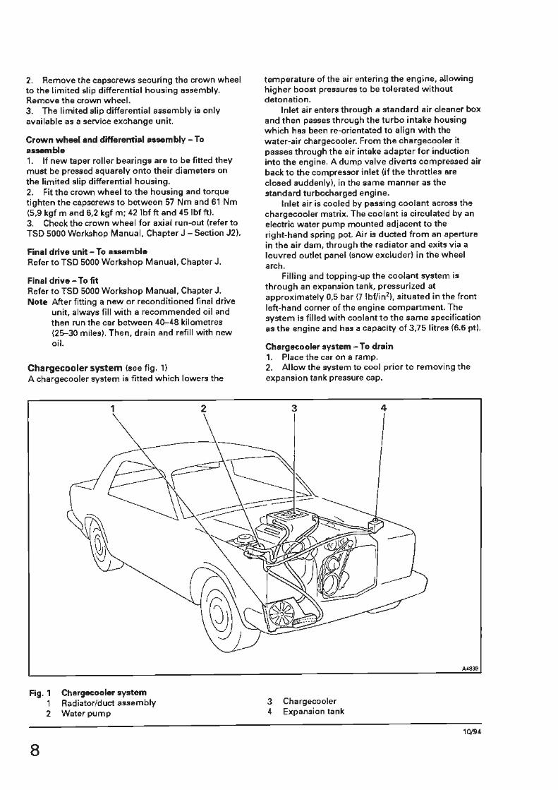
Chargecooler system (see fig. 1) A chargecooler system is fitted which lowers the
Fig. 1 1 2
8
Chargecooler system Radiator/duct assembly Water pump
temperature of the air entering the engine, allowing higher boost pressu,es to be tolerated without detonation.
Inlet air enters through a standard air cleaner box and then passes through the turbo intake housing which has been re-orientated to align with the water-air chargecooler. From the chargecooler it passes through the air intake adapter for induction into the engine. A dump valve diverts compressed air back to the compressor inlet (if the throttles are closed suddenly), in the same manner as the standard turbocharged engine.
Inlet air is cooled by passing coolant across the chargecooler matrix. The coolant is circulated by an electric water pump mounted adjacent to the right-hand spring pot. Air is ducted from an aperture in the air dam, through the radiator and exits via a louvred outlet panel (snow excluder) in the wheel arch.
Filling and topping-up the coolant system is through an expansion tank, pressurized at approximately 0,5 bar {7 lbf/in2), situated in the front left-hand corner of the engine compartment. The system is filled with coolant to the same specification as the engine and has a capacity of 3,75 litres (6.6 pt).
Chargecooler system - To drain 1. Place the car on a ramp. 2. Allow the system to cool prior to removing the expansion tank pressure cap.
3 4
3
Chargecooler Expansion tank
4
A4839
10/94

3. Place a container beneath the lower hose outlet on the chargecooler radiator. Slacken and remove the bottom hose. 4. Drain the coolant into the container. 5. Fit the bottom hose.
Chargecooler system - To fill 1. Remove the filler plug in the top of the chargecooler. 2. Disconnect the chargecooler to header tank hose at the adapter located centrally in the length of hose. Fit a hose clamp to seal off the header tank hose. 3. Fill the system with coolant through the filler hole. Replace the filler plug and tighten when the system is full. 4. Remove the header tank filler cap and half fill the tank with coolant. 5. Reconnect the chargecooler to header tank hose at the adapter and tighten the hose clips. Remove the hose clamp. 6. Replace the filler cap on the header tank. 7. Remove the pump relay (grey) between the right-hand side spring pot brackets. Using a link wire between the two terminals in the relay base (see fig. 2), bridge the contacts for ten seconds to operate the electric water pump. Remove the link wire and replace the pump relay. Note The ignition switch does not need to be on
during the above operation. 8. Remove the filler cap from the header tank and top-up to approximately 5 mm (0.197 in) below the bottom of the filler neck. 9. Fit the pressure cap.
Chargecooler system -To top-up 1. Allow the system to cool and then remove the pressure cap from the expansion tank. 2. Top-up with coolant to approximately 5 mm (0.197 in) below the bottom of the filler neck. 3. Fit the pressure cap.
Chargecooler - To remove and fit 1. Drain the coolant {see Chargecooler system - To drain). 2. Disconnect the electrical conne<:tions from the idle speed actuator and the air temperature thermistor at the rear of the chargecooler. Slacken the wormdrive clips securing the idle speed actuator and pivot it clear of the chargecooler. 3. Remove the coil covers. Then, disconnect the electrical connections from the coils. 4. Remove the setscrews from the coil racks, to allow the coil assemblies to be moved slightly away from the chargecooler. 5. Slacken the chargecooler to throttle body and chargecooler to turbocharger connecting collar wormdrive clips. Then, ease both collars away from the chargecooler. 6. Remove all the hoses connecting the front of the chargecooler to the turbocharger. Remove the
10/94 Printed in England © Rolls-Royce Motor Cars Limited 1994
DODD DODD
A , 1
Fig. 2 Bridging the relay base
A'840
Fig. 3 Spare wheel location (Bentley Turbo S}
coolant return hose from the chargecooler. Then, remove the feed hose to the chargecooler. 7. Remove the header tank to chargecooler hose. 8. Remove the nuts securing the chargecooler to the four mounts. 9. Carefully ease the chargecooler up and away from the engine, ensuring all pipes, electrical connections, etc., have been removed.
Drain any remaining coolant into the container used for draining the system. 10. Fit the chargecooler by reversing the removal procedure.
TS05601
9
Electric water pump- To remove and fit 1. Drain sufficient coolant to ensure that the level is below the water pump (refer to Chargecooler system -To drain).
mat, fold back the soundproofing mat to protect the bodywork and bumper from damage when lifting the spare wheel from the luggage compartment. 3. Remove the panel protecting the spare wheel by turning the location screws anti-clockwise half a turn either by hand or with a suitable screwdriver.
2. Disconnect the electrical plug adjacent to the water pump assembly. 3. Slacken and remove the coolant hoses from the water pump. 4. Remove the two setscrews securing the pump assembly to the right-hand spring pot. Lift the assembly clear. 5. To fit the water pump, reverse the removal procedure noting that the securing bolts should be torque tightened in accordance with the figures quoted in Chapter P.
Radiator/fan assembly-To remove and fit 1. Remove the front bumper assembly (refer to Chapter S). 2. Remove the snow excluder from the right-hand wheel arch. 3. Drain the coolant (see Chargecooler system - To drain). 4. Disconnect the top hose from the radiator stub pipe. 5. Disconnect the fan assembly electrical plug and socket, situated at the rear of the headlamp units. 6. Remove the nuts and washers securing the assembly to the three rubber mounts. 7. Withdraw the radiator/duct assembly complete. 8. Dismantle the radiator from the assembly. 9. To fit the radiator, reverse the removal procedure.
Wheels and tyres Spare whee4 - To remove (Bentley Turbo S) 1. Lift the luggage compartment lid.
4. Lift the panel and pull rearwards to remove. S. Using the lifting strap, remove the spare wheel (complete with cover) from the luggage compartment. Note The wheel cover is provided to ease the
removal procedure and should not be discarded.
Spare wheel-To fit {Bentley Turbo S} Reverse the procedure given for removal noting the following. 1. Ensure that the lifting strap and spare wheel cover are attached to the wheel. Note Tyres fitted to Bentley Turbo Sand Bentley
Continental S a,e uni-directional, fitting procedures and precautionary notes for these tyres are described in TSD 5000 Workshop Manual, Chapter R.
Recommended tyres and tyre pressures This section refers to the recommended tyres and tyre pressures for the Bentley Turbo Sand Bentley Continental S.
The removal, balancing, and fitting procedures of the wheel and tyre assemblies, are described in TSD 5000 Workshop Manual, Chapter R.
Bentley Turbo Sand Bentley Continental S motor cars are fitted with 71/ 2 J x 17 aluminium alloy wheels.
2. Fold the luggage compartment floor carpet from left to right (see fig. 3), to reveal the soundproofing
To ensure the designed handling characteristics of the car are achieved, it is important to maintain the differential in tyre pressures between the front and rear wheels.
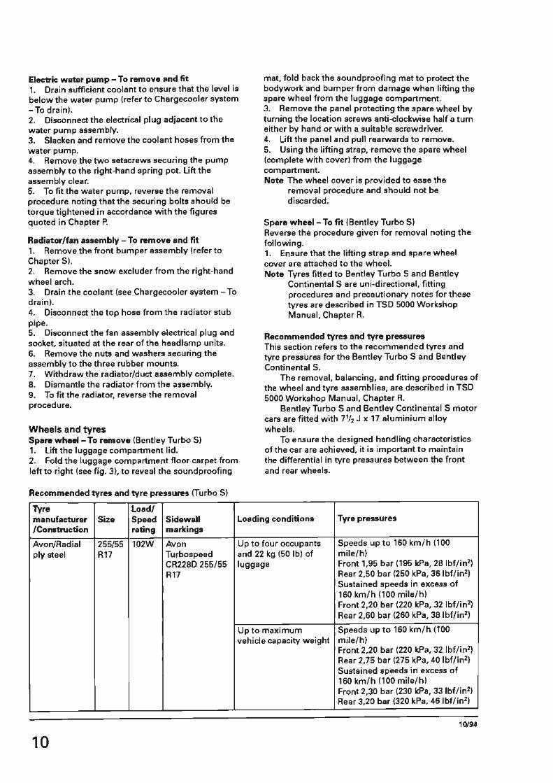
Recommended tyres and tyre pressures (Turbo S)
Tyre load/ manufacturer Size Speed Sidewall Loading conditions Tyre pressures /Construction rating markings
Avon/Radial 255/55 102W Avon Up to four occupants Speeds up to 160 km/h (100 ply steel R17 Turbospeed and 22 kg (50 lb) of mile/h)
CR2280 255/55 luggage Front 1,95 bar (195 kPa, 28 lbf/in2)
Rl7 Rear 2,50 bar (250 kPa, 36 lbf/in2)
Sustained speeds in excess of 160 km/h (100 mile/h) Front 2,20 bar (220 kPa, 32 lbf/in2)
Rear 2,60 bar (260 kPa, 38 lbf/in2)
Up to maximum Speeds up to 160 km/h (100 vehicle capacity weight mile/h)
Front 2,20 bar (220 kPa, 32 lbf/in2) Rear 2,75 bar (275 kPa, 40 lbf/in2) Sustained speeds in excess of 160 km/h (100 mile/h) Front 2,30 bar (230 kPa, 33 lbf/in2} Rear 3,20 bar (320 kPa, 46 lbf/in2)
10/94
10
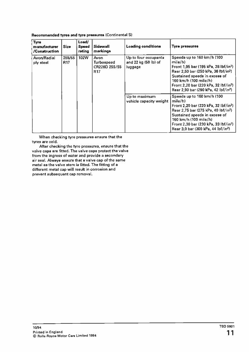
Recommended tyres and tyre pressures (Continental S)
Tyre Load/ manufacturer Size Speed Sidewall /Construction rating markings
Avon/Radial 255/55 102W Avon ply steel R17 Turbospeed
CR2280 255/55 R17
When checking tyre pressures ensure that the tyres are cold.
Loading conditions
Up to four occupants and 22 kg (50 lb) of luggage
Up to maximum vehicle capacity weight
After checking the tyre pressures, ensure that the valve caps are fitted. The valve caps protect the valve from the ingress of water and provide a secondary air seal. Always ensure that a valve cap of the same metal as the valve stem is fitted. The fitting of a different metal cap will result in corrosion and prevent subsequent cap removal.
10/94 Printed in England © Rolls-Royce Motor Cars Limited 1994
Tyre pressures
Speeds up to 160 km/h (100 mile/h} Front 1,95 bar (195 kPa, 28 lbf/in2)
Rear 2,50 bar (250 kPa, 36 lbf/in2) Sustained speeds in excess of 160 km/h (100 mile/h) Front 2,20 bar (220 kPa, 32 lbf/in2)
Rear 2,90 bar (290 kPa, 42 lbf/in2)
Speeds up to 160 km/h (100 mile/h) Front 2,20 bar (220 kPa, 32 lbf/in2)
Rear 2,75 bar (275 kPa, 40 lbf/in2)
Sustained speeds in excess of 160 km/h {100 mile/h) Front 2,30 bar (230 kPa, 33 lbf/in2)
Rear 3,0 bar (300 kPa, 44 lbf/in2)
TSO 5601
11

Engine Management System tntroduction The following changes have been made to the engine management system compared to 1994 model year cars.
Replaced parts
Bosch ECM, Bosch M3.3 Motronic, Engine run timer, Luxor boost and Avant transient boost control modules.
Auxiliary air solenoid valve (Tecalemit>.
Bosch air meter.
Camshaft sensor.
Loom changes.
Diagnostics {Blink codes).
The engine management system is now controlled by a Zytek engine control module {ECM) mounted in the same position as the replaced Bosch ECM. The Zytek control module (and additional internal software) is capable of coping with many more features than the Bosch system. The Zytek system incorporates boost and transient boost features.
Additional sensors (see fig. 4) which feed information to the Zytek system are: (i) air intake temperature sensor, mounted on the outlet side of the chargecooler. (iii fuel temperature sensor, mounted beneath the chargecooler.
1 2
New parts
Zytek ECM {plus new cooling enclosure) . Air intake temperature sensor. Fuel temperature sensor.
Boost control valve
Manifold absolute pressure {MAP) sensor.
'Hall' effect sensor (plus new timing disc on camshaft).
Engine, right and left-hand valance, main distribution, gearbox and chargecooler looms.
Mastercheck engine/transmission data card.
The auxiliary air valve (Tecalemit) has been replaced by an additional boost control valve which is mounted at the front end of the chargecooler.
The load sensing medium has also changed from an air flow to a pressure based system. This system is measured by a manifold absolute pressure (MAP) sensor mounted under the right-hand front wing.
The camshaft signal is now fed from a 'Hall' effect sensor which necessitates a new timing disc. This timing disc is a single tooth gear fitted to the camshaft as the previous type.
Loom changes have been made to the engine, right and left-hand valance, main distribution,
3 4
Fig. 4 Engine management system - new component locations 1 Manifold absolute pressure (MAP) sensor 3 Air intake temperature sensor (IAT) 2 Fuel temperature sensor 4 Boost control valve
10/94
12

gearbox and chargecooler systems. Finally, the diagnostics procedure (Blink codes)
has been replaced by a Mastercheck card from
Omitec which permits the new engine management and gearbox systems, etc., to be interrogated via a new connector.
Diagnostic trouble codes
Engine codes
Code Description
P0105 Manifold absolute pressure/barometric pressure circuit malfunction
P0106 Manifold absolute pressure/barometric pressure circuit range/performance malfunction
P0110 Intake air temperature circuit malfunction
P0115 Engine coolant temperature circuit malfunction
P0116 Engine coolant temperature circuit range/performance problem
P0120 Throttle/pedal position sensor A circuit malfunction
P0121 Throttle/pedal position sensor A circuit range/performance malfunction
P0125 Insufficient coolant temperature for closed loop fuel control
P0130 0 2 sensor circuit malfunction ('A' bank, sensor 1)
P0131 0 2 sensor circuit low voltage ('A' bank, sensor 1)
P0132 02 sensor circuit high voltage ('A' bank, sensor 1)
P0133 0 2 sensor circuit slow response ('A' bank, sensor 1)
P0135 0 2 sensor heater circuit malfunction ('A' bank, sensor 1)
P0171 System too lean
P0172 System too rich
P0180 fuel temperature sensor A circuit malfunction
P0201 Injector circuit malfunction - Cylinder A 1
P0202 Injector circuit malfunction - Cylinder A3
P0203 Injector circuit malfunction - Cylinder B3
P0204 Injector circuit malfunction - Cylinder A2
P0205 Injector circuit malfunction - Cylinder B2
P0206 Injector circuit malfunction - Cylinder 81
P0207 Injector circuit malfunction - Cylinder A4
P0208 Injector circuit malfunction - Cylinder 84
P0230 Fuel pump primary circuit malfunction
P0243 Turbocharger wastegate solenoid A malfunction
P0247 Turbocharger wastegate solenoid B malfunction
P0300 Random/multiple cylinder misfire detected
P0301 Cylinder A 1 misfire detected
P0302 Cylinder A3 misfire detected
P0303 Cylinder B3 misfire detected
P0304 Cylinder A2 misfire detected
P0305 Cylinder B2 misfire detected
P0306 Cylinder B1 misfire detected
P0307 Cylinder A4 misfire detected
P0308 Cylinder B4 misfire detected
P0325 Knock sensor 1 circuit malfunction ('A' bank)
P0330 Knock sensor 2 circuit malfunction ('B' bank)
10/94 TS05601
Printed in England © Rolls-Royce Motor Cars Limited 1994 13

Code Description
P0335 Crankshaft position sensor circuit malfunction
P0340 Camshaft position sensor circuit malfunction
P0351 Ignition coil A 1 primary/secondary circuit malfunction
P0352 Ignition coil A3 primary/secondary circuit malfunction
P0353 Ignition coil 83 primary/secondary circuit malfunction
P0354 Ignition coil A2. primary/secondary circuit malfunction
P03SS Ignition coil 82 primary/secondary circuit malfunction
P0356 Ignition coil 81 primary/secondary circuit malfunction
P0357 Ignition coil A4 primary/secondary circuit malfunction
P0358 Ignition coil B4 primary/secondary circuit malfunction
P0410 Secondary air injection system malfunction
P0411 Secondary air injection system incorrect flow detected
P0443 Evaporative emission control system purge control valve circuit malfunction
P0460 Fuel level sensor circuit malfunction
P0500 Vehicle speed sensor malfunction
P0505 Idle control system malfunction
P0506 Idle control system rpm lower than expected
P0507 Idle control system rpm higher than expected
P0601 Internal control module memory checksum error
P1000 Air conditioning relay
P1001 Charge cooler pump relay
P1002 Charge cooler fan relay
P1003 Charge cooler thermistor
P1004 Run timer relay
P1005 Catalyst temperature thermocouple (if fitted)
P1006 TCM induced MIL
P1007 ECM internal barometer circuit malfunction
P1008 ECM internal temperature sensor circuit malfunction
P1009 Excessive ECM internal temperature
P1340 After start camshaft position sensor circuit fault
P1344 Camshaft position sensor circuit intermittent
Transmission codes - TCM Inputs
P0107 Barometric pressure sensor signal low
P0108 Barometric pressure sensor signal high
P0122 Throttle position sensor signal low
P0123 Throttle position sensor signal high
P0237 Turbo boost sensor signal low
P0238 Turbo boost sensor signal high
P0703 Brake switch input malfunction
P0706 Transmission range sensor circuit range/performance
P0712 Transmission fluid temperature sensor circuit low input
P0713 Transmission fluid temperature sensor circuit high input
P0715 Turbine/input speed sensor circuit malfunction
10/94
14

Code Description
P0716 Turbine/input speed sensor range/performance
P0720 Output speed sensor circuit malfunction
P0721 Output speed sensor circuit range/performance
P0726 Engine speed input circuit range/performance
P0727 Engine speed input circuit no signal
P1780 Torque reduction signal malfunction
P1783 Transmission fluid over-temperature condition
P1794 System voltage malfunction
P1897 Warm-up signal circuit malfunction
P1898 Manual mode circuit malfunction
P1899 Sport mode circuit malfunction
Transmission codes - TCM Outputs
P0605 TCM PROM checksum error
P0730 Incorrect gear ratio
P0741 Torque converter clutch system stuck off
P0742 Torque converter clutch system stuck on
P0743 Torque converter clutch pulse width modulated solenoid system electrical
P0748 Pressure control solenoid circuit electrical
?0751 Shift solenoid 'I( performance
P0753 Shift solenoid • I( electrical
P0756 Shift solenoid 'B' performance
P0758 Shift solenoid 'B' electrical
P0780 Shift malfunction (Maximum adapt/Long shift)
P1739 Transmission component slipping
Connecting the test equipment 1. Carry out the usual workshop safety precautions, including fitting the car protection kit and wing covers.
Isolate the transmission in park and remove the gearchange isolating fuse from the main fuseboard. 2. Connect the Mastercheck diagnostic system equipment (excluding the printer) to the car via the 48-way diagnostic socket at the inboard end of the lower facia stowage compartment. 3. Insert the relevant engine/transmission data card (printed side uppermost) into the back of the keypad unit. 4. Depress the F2 button on the keypad unit. This will activate the system and the keypad unit text screen will then operate.
One of five possible modes of operation can then be accessed, i.e. P CODE DISPLAY, P CODE CLEAR, THROTTLE SET, FUEL TRIM, and LIVE DATA ECM. S. The P CODE DISPLAY mode will show any trouble codes.
Proceed as directed on the keypad unit screen. 6. Continue through each question until the test is complete.
10/94 Printed in England © Rolls-Royce Motor Cars Limited 1994
7. A print out of the test results can be made when the print symbol appears on the text screen. The operator will be prompted to plug the printer into the socket on the power harness after the print key has been depressed. Note The printer should be disconnected from the
system when it is not being used.
Manifold absolute pressure sensor - To remove and fit (see fig. 4) 1. Carry out the usual workshop safety precautions. 2. Fit the car protection kit and wing covers. 3. Chock the rear road wheels. 4. Remove the gearchange isolating fuse from the main fuseboard. Then, either turn the battery master switch (if fitted) to the OFF position or disconnect the battery leads. 5. Raise the front of the car and remove the right-hand road wheel. 6. Remove the rear section of the underwing sheet (see TSO 5000 Workshop Manual, Chapter S). 7. Detach the electrical plug from the manifold absolute pressure sensor.
TSO 5601
15
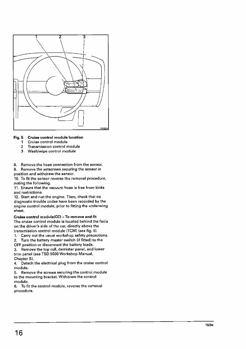
Fig.S 1 2 3
Cruise control module location Cruise control module Transmission control module Wash/wipe control module
8. Remove the hose connection from the sensor. 9. Remove the setscrews securing the sensor in position and withdraw the sensor. 10. To fit the sensor reverse the removal procedure, noting the following. 11. Ensure that the vacuum hose is free from kinks and restrictions. 12. Start and run the engine. Then, check that no diagnostic trouble codes have been recorded by the engine control module, prior to fitting the underwing sheet.
Cruise control module(CC) - To remove and fit The cruise control module is located behind the facia on the driver's side of the car, directly above the transmission control module (TCM) (see fig. 5). 1. Carry out the usual workshop safety precautions. 2. Turn the battery master switch (if fitted) to the OFF position or disconnect the battery leads. 3. Remove the top roll, demister panel, and lower trim panel (see TSD 5000 Workshop Manual, Chapter S). 4. Detach the electrical plug from the cruise control module. 5. Remove the screws securing the control module to the mounting bracket. Withdraw the control module. 6. To fit the control module, reverse the removal procedure.
16 10/94

Figure 6
Engine Management System Theoretical Wiring Diagram
Introduction The information contained on pages 18 and 19 are intended to supplement that contained within TSD 5500 Workshop Manual Electrical.
Identification of components, cable routes, and connections can be made using the wiring diagram and component locations within this section.
10/94 Printed in England © Rolls-Royce Motor Cars Limited 1994
TS05601
17

Key to fig. 6 011 Cruise control actuator 011 a Position potentiometer 011b Motor 011c Clutch 013a Gearchange actuator micro-switches 014 Idle speed actuator 020 Alternator 022 Battery 032 Air injection pump clutch. Cars fitted with catalytic
converters 035 Anti-lock braking system control module 035a Wheel speed sensor outputs 044 Cruise control control module 047 Transmission control module 050 Engine control module 058 Fusible link 131 Automatic air conditioning unit fan - left-hand 132 Automatic air conditioning unit fan - right-hand 135 Fuel pump 147 Starter motor 147a Starter solenoid 174a Throttle position potentiometer - engine 201 Accessories relay 202 Automatic air conditioning unit control relay 205 Compressor relay 218 Fuel pump relay 224 Ignition relay 1 225 Ignition relay 2 243 Starter motor solenoid relay 244 Starter motor inhibit relay 245 Stop lamps relay- green casing 246 Stop lamp failure relay 259 Fans speed resistor block 263 Anti-lock braking system wheel speed sensor -
left-hand front 264 Anti-lock braking system wheel speed sensor -
left-hand rear 265 Anti-lock braking system wheel speed sensor -
right-hand front 266 Anti-lock braking system wheel speed sensor -
right-hand rear 272 Coolant temperature sensor 278 Knock sensor 'I( bank 279 Knock sensor 'B' bank 280 Camshaft sensor 284 Crankshaft sensor 286 Boost control solenoid 293 Purge control valve and diode. Cars fitted with a fuel
evaporative emission control system 295 Water tap solenoid 296 Sparking plugs 299 Battery master switch. Cars other than those
conforming to a German specification 313 Cruise control switches 331 Fuel/oil level change-over switch 332 Fuel pump cut-off switch 351 Neutral start switch - gearchange actuator 352 Neutral start switch - gear selector 361 Stop lamps switch 361a 'Off' position 361b 'On' position 37Sa Ignition switch 376 Tachometer 378 Air injection temperature switch. Cars fitted with
catalytic converters 390 Fuel level transmitter 391 Oil level transmitter 395 Vehicle diagnostic socket pin(sl 401 Speedometer
18
402 Warning panels 403e Luggage compartment fuse S 528 Ignition coils S30 Injector valves 531 Air intake temperature sensor 537 Main engine management relay 538 Air injection relay. Cars fitted with catalytic converters 689 Charge cooler coolant temperature sensor 690 Fuel temperature sensor 691 Lambda sensor - pre catalyst 692 Manifold absolute pressure sensor 695 Charge cooler fan relay 696 Charge cooler fan 697 Charge cooler pump relay 698 Charge cooler pump 699 Catalyst thermocouple 700 On-board diagnostics II connector 701 Data link connector 702 Charge cooler fuse 703 Engine ancillaries fuse
The theoretical wiring diagram on page 19 is primarily for the engine management system. Howeve, to aid diagnosis certain ancillary circuits are also shown in skeletal form to indicate their inter connection with the engine management system circuits.
If more detail is required on the ancillary circuits refer to TSO 5500 Workshop Manual Electrical.
An indication of the page number is given by the
symbol 3&-3 38-S 3&-11 3&-13
[DI] [[TI]
The position of the ancillary circuit is indicated on the symbol by a black square as shown in the following example.
38-3 38-5 3&-11 38-13
G:]] [!TI]
21. Battery and starter system
The example above shows the location of circuit 21, Battery and starter system for Bentley Turbo S and Bentley Continental S motor cars.
To locate the Battery and starter system circuit for Bentley Turbo S Reference should be made to page 38-3 of TSO 5500 Workshop Manual Electrical.
To locate the Battery and starter system circuit for Bentley Continental S Reference should be made to page 38-1 l of TSD 5500 Workshop Manual Electrical.
10/94

38-3 38-S 3.!1-11 18-13
QIDDlD 21.BatteJV and starter system
... ----
I I
: 0 • ... _._
352.Neutral start switch -gear seleetor
244.Starter motor inhiM relay
38-3 S'l-5 38-11 3.1-13
OIOOJIJ 1.Alternator
IQJIH I _._ ____ _,,'<:ti ll6-.,-~~ __ -_-0_20_-.Alt_. _·emat_-. ; ;
·---·-·-; 058.Fusibl& lilk
0686
ie -l n-s 38 -11 3.\-13
DJLJOJI] 25.lnstruments, instruments module and warning panels
401.Speedometer
' ) )
!
r' - .. ,
' • I
' 390.Fuel
: ' .~ : -,.._ I tranffllittsr L- -~·
~ -,
: 391.011 , level : ur.illT'ittar
! .. . - -
38-3 38-5 38-11 38-13
DlDCrJ 16.Cruise control and stop lamps
011 Cruillo comrol acluator iii
38-3 38-6 38-11 38-13
38 - 3 38 - s CIIDCTI 31 - 11 38 - 13
DIDOil:J 17.Anti- lock braking 28.Transmission system !ABS)
047.Transmission oontl~ module
-'-® ~ : . 035.ABS ~
oontrolmodUle
~ ©+-L
o.sur;
38-3 38 - 5 38-11 38 - 13
l'.:JIDOJI] 2.Switchbox
38-3 38-5 3$-11 38-13
ore :..:..illJ 20.Automatic air conditioning
~ - 131.132. __ 6_ ¢_ ~ ,-1-r I : ACU fan; 259.fans speed 0 , , ,&mor t,ock : b : , ~ •295.Water , • ··- " UMl --~ , bio , _ )_: tsp solenoid : :~ :
~~·=·-- ' -~ · ~-
t.. ·---- -
..----a : ! t ' - -~> · I t
' '.
;: :--?-~-liJilioo' 0--- -rr.,y \-~
' ~ UlflG • 1...
:~
224lgrition i,loy 1
21l5.Compn,:ssor relay
--1-1-+-1-i-l--l-~·~ ..... -~<l~--------uou -
-
-1-
·-, ....
-~ -
!H
0,5UI(
l ,(/(W
' "-:~ : 702.Cherge 1 cooler
~ . -- -, o.. ' 703.Engine ~ antilliaries
~ ! ! ! ! ! i ; 395.Vell.:k? ~ !SI ' ... 403e diagnostlc O ::I - • ,5 ( ) - 700.08011 Conneclor
1 ~ wqgage sockel pins • _
, ~ compartm!flt 0""" ;i©©-r- ~,fA~f:~4i_; 701.0eta ~nk connector F2 ' , c
•"" • : fuse fuse
·--~ ·: r:-·?5i!~i--~~---:! ~8.Air ! t 1.(11.11 : I ~ . ~ Injection
• • • ' · ~ relay ! •- • • 1 _ _ ,.1 I -- t
378.032.Air injection temp. - • - - - - • • swilch ano pcimp elute~
8 8
IJIIY IJJN( I
:~. -• fuse D.3'IU -- i --' ~3:L;c> 0> 2.oiqt WOl IDl!I
1 - - - 1
I ~ J .332.Fu/ § _ .. ------- l~y :: : : -···c5 -- ' <JEY '1P •pwnp ' ~ 2JA I
, ,' : 202ACU IH ! ~ ~~:;~ t1 : ~0- ) ! I!!]!!~ Bq<)~ __________ j j
-l.tHf LONI' 100¥
- • 3.t.llt A4
~ 135.Fuel pump CVI B2 C>,1 A4 CVI B4
- ~ -- 1 .! :Vn-ol ~:~-\ --t: ;~~~} ! ~ ~~ ; ;::~ ~~~ ~ : : i -~Y!~1-: «-01~\ _!:.Yl_~3-, t}Cy!Al , ~ & ::I , ~ , 537.Main engine · f- - ~ ~ ! I .._ '-:."~ ~ u l ' , ., , ,
- () ( ' relay 1T1811agement relil'I i i ~ • - G.58G "' ""' ·- - - - - - - - - - - - - - - - - " • 1 , • z , ~-----+-"IQ!il'""--+--+----'1,_.!HI..:;... 1 -:r- ' l!l 3.fJHf ol; •,.__ 1.c«II ® 050.Engine • ·
1
·_ •0- · •15_- · • 1 _ •
: 050.EngiM : tOl\trolmodule
.-----, ' '
,_ 2 • _ 1_ ..
- - .__ . ·u·---. 5.30. ;i:: Injector !! ; 1 val'/es
0 l I
"3."''1Nf.<=• -"''OYIK""'-+---~~"'"~'"l--+----_-_-_. ---- ::! UICH l.ool 1.crN "' contnlCmodule !! _ _"' "I ~= ~= = ::: i: ~'.::::.::~===========~~=·=========~---1.<Hl 1.llNU :: l.llhll~ =:'. 1,00! 10!0 , ...
r - --- ___ ____________ :".'." _________________ ~~--- - --- - - --- ----- - ------, ~ · ~~ ~.'l\.....~1.0l!f""--------',,c:,.,...--------',f//ff"""----<I
i ------------ ------------------- ------- ... Tl 0'" ' ~ ? UIICI' ·- I.Qt(\' 1 r---------------------- ~ v.;, ~6)-_,_,1111<1)~'-------'l~Ql(\/,,,_ ______ -'1.lllll.,,,,_ ______ _eLQIQj,,.,_ ____ -<I
Q.5,(8·' - : : ~------------·---- -- ... ---·--------------------- ------------1 : . ~------_.!,!1.-!!j"s._ ______ .!!,::!!i. !!._ _____ ___!LIR&c!!:!!:-______ --<I
0.58'1 '.~ : : : r ----------··--- ----------------- ----------- --- --- - --- "., W ~ ~'-------"'-""""'"'-"------~S!!-------!al'-IIICI.G~---------1"".Dll&""--o o.5N I - : : : : r:--------- -------------------------·------------- ..1. Q.5S ' - U:ilt ,-. - - ------------------ ---------------------·------------------------------- .. OSI$ • '3' I I I I t I ll1ill ~ ID6 •··---------- ::::::::::::::::::::::::::::::::::::::::::::::::::::::·------.,.
OSH I ~ : ~ : : : r- ------ -----------------------------------------· w ~ 1 1(l$ :::::::::::1: :::::::::::::-::-::::::::::::::::-::::-::::::::::~---- _ ..
~-!°·
16KR
W i ® : : : : : r.-- --------------------------------------J. O.!Ydl ~ 11lk.-------- -~= ::::::::::::::::::::::::::::::::::::::.·-------" !l3i I :: _______ :, •_?_"'_"_ ::: : -> ;:,,::' :!, ,:::::- ------------------------------------- - --· .- l .... ; •,oo ::::::-: :~: ::::::::::::::::::::::::::::::-------· CO · ~ ~ ~ ~ ~ ~ ~ ...!., 111AOU :,:_:_:_-~_ : _ _ :: :::::::::::::::::::::; - ·- -------------- ..
27.Engine management system = = = : Det10tes S(reeood celll8s 19 Fig. 6 Engine management theoretical wiring diagram

Body and Coachwork Introduction Bentley Turbo S is similar to 1994 MY Turbo R but has certain unique body and coachwork features. The following information is intended to supplement that contained within TSD 5000 Workshop Manual.
The bumpers are similar in construction to Bentley Continental R being one piece mouldings with no separate airdam at the front.
The spare wheel is stowed inside the luggage compartment under the floor.
Bumpers Each bumper assembly is constructed around an aluminium beam. The outer surface of the bumper consists of a moulding with foam bonded to its inner surface. This outer skin is attached to the beam via studs bonded to the moulding.
Fig. 7 Front bumper assembly
A moulding is fitted to the front bumper to carry the registration plate.
The lower air vents are secured into position by screws into the front bumper outer cover. Extension pieces are screwed to the lower edge of the rear bumper moulding ..
Each end of the outer cover is secured to the body by means of a bobbin fixed via a bracket assembly to the bumper. The bobbin slides into a channel fixed to the body.
The bumper assembly is mounted to the bumper brackets via an adapter. The bumper brackets are then bolted to the longerons at the front and rear of the car.
The bumper mounting brackets are secured to the longeroo by two setscrews and two locking bolts which fix the position of the mounting bracket relative to the longeron.
10/94 TSO 5601
Printed in England © Rolls-Royce Motor Cars Limited 1994 21
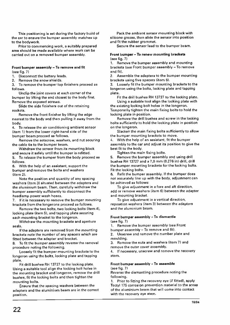
This positioning is set during the factory build of the car to ensure the bumper assembly matches up to the bodywork.
Prior to commencing work, a suitably prepared area should be made available where work can be carried out on a removed bumper assembly.
Front bumper assembly-To remove and fit (see fig. 71 1. Disconnect the battery leads. 2. Remove the snow shields. 3. To remove the bumper top finishers proceed as follows.
Unclip the joint covers at each corner of the bumper by lifting the end closest to the body first. Remove the exposed screws.
Slide the side finishers out of the retaining sockets.
Remove the front finisher by lifting the edge nearest to the body and then pulling it away from the body. 4. To release the air conditioning ambient sensor (item 1) from the lower right-hand side of the bumper beam proceed as follows.
Remove the setscrew, washers, and nut securing the cable tie to the bumper beam.
Withdraw the sensor from its mounting block and secure it safely until the bumper is refitted. 5. To release the bumper from the body proceed as follows. 6. With the help of an assistant. support the bumper and remove the bolts and washers (item 2).
Note the position and quantity of any spacing washers (item 3) situated between the adapters and the aluminium beam. Then, carefully withdraw the bumper assembly sufficiently to disconnect the headlamp power wash hoses. 7. If it is necessary to remove the bumper mounting brackets from the longerons proceed as follows.
Remove the two bolts, two locking bolts (item 4), locking plate (item 51, and tapping plate securing each mounting bracket to the longeron.
Withdraw the mounting brackets and aperture seals.
If the adapters are removed from the mounting brackets note the number of any spacers which are fitted between the adapter and bracket. 8. To fit the bumper assembly reverse the removal procedure noting the following.
Loosely fit the bumper mounting brackets to the longeron using the bolts, locking plate and tapping plate.
Fit drill bushes RH 13727 to the locking plate. Using a suitable tool align the locking bolt holes in the mounting bracket and longeron, remove the drill bushes, fit the locking bolts and then tighten the mounting bolts.
Ensure that the spacing washers between the adapters and the aluminium beam are in the correct position.
22
Pack the ambient sensor mounting block with silicone grease, then slide the sensor into position and fit the rubber grommet.
Secure the sensor lead to the bumper beam.
Front bumper - To renew mounting brackets (see fig. 7) 1. Remove the bumper assembly and mounting brackets (see Front bumper assembly- To remove and fit). 2. Assemble the adapters to the bumper mounting brackets using five spacers (item 6). 3. Loosely fit the bumper mounting brackets to the longeron using the bolts, locking plate and tapping plate.
Fit the drill bushes RH 13727 to the locking plate. Using a suitable tool align the locking plate with
the existing locking bolt holes in the longeron. Temporarily tighten the main fixing bolts to hold the locking plate in position.
Remove the drill bushes and screw in the locking bolts sufficiently to hold the locking plate in position on the longeron.
Slacken the main fixing bolts sufficiently to allow the bumper mounting brackets to move. 4. With the help of an assistant, fit the bumper assembly to the car and adjust its position to give the best fit to the body.
lighten the main fixing bolts. 5. Remove the bumper assembly and using drill bushes RH 13727 and a 7 ,0 mm (0.276 in) drill, drill the bumper mounting brackets for the locking bolts. Fit the locking bolts. 6. Refit the bumper assembly. If the bumper does not accurately line up with the body, adjustment can be achieved as follows:
To give adjustment in a fore and aft direction, add or remove washers (item 6) between the adapter and mounting bracket.
To give adjustment in a vertical direction, reposition washers (item 31 between the adapters and the aluminium beam.
Front bumper assembly - To dismantle (see fig. 7) 1. Remove the bumper assembly (see Front bumper assembly - To remove and fit). 2. Unscrew and remove the number plate and moulding. 3. Remove the nuts and washers (item 7) and remove the outer cover assembly. 4. If necessary, unscrew and remove the recovery stem.
Front bumper aHembly-To assemble {see fig. 7) Reverse the dismantling procedure noting the following. 1. Prior to fitting the recovery eye (if fitted), apply Tectyl 175 corrosion prevention material to the areas of the aluminium beam that will come into contact with the recovery eye stem.
10/94

This will prevent corrosion caused by the contact of dissimilar metals.
Rear bumper assembly- To remove and fit (see fig. 8) 1. To remove the bumper top finishers proceed as follows.
Unclip the joint covers at each corner of the bumper by lifting the end closest to the body first. Remove the exposed screws.
Slide the side finishers out of the retaining sockets. Remove the rear finisher by lifting the edge nearest to the body and then pulling it away from the body. 2. To release the bumper from the body proceed as follows.
Fig. 8 Rear bumper assembly
3. With the help of an assistant, support the bumper and remove the bolts and washers (item 1).
Note the position and quantity of any spacing washers (item 2) situated between the adapters and the aluminium beam. Then, carefully withdraw the bumper assembly and remove. 4. If it is necessary to remove the bumper mounting brackets from the longerons proceed as follows.
Remove the two bolts, two locking bolts (item 3), locking plate (item 4). and nuts and washers securing each mounting bracket to the longeron. Withdraw the mounting brackets and aperture seals. Note For some markets a towing eye is fitted to the
left-hand longeron and is secured using the same fixing bolts as the bumper mounting
10/94 TSO 5601
Printed in England © Rolls-Royce Motor Cars Limited 1994 23

brackets. The locking bolts are fitted to the towing eye side plate.
If the adapters are removed from the mounting brackets note the number of any spacers which are fitted between the adapter and bracket. 5. To fit the bumper assembly reverse the removal procedure noting the following.
Loosely fit the bumper mounting brackets to the longeron using the bolts. locking plate and tapping plate. Fit drill bushes RH 13727 to the locking plate.
Using a suitable tool align the locking bolt holes in the mounting bracket and longeron, remove the drill bushes, fit the locking bolts and then tighten the mounting bolts.
Ensure that the spacing washers between the adapters and the aluminium beam are in the correct position.
Rear bumper - To renew mounting brackets (see fig. 8) 1. Remove the bumper assembly and mounting brackets (see Front bumper assembly - To remove and fit). 2. Assemble the adapters to the bumper mounting brackets using five spacers (item 51. 3. Loosely fit the bumper mounting brackets to the longeron using the bolts, locking plate and tapping plate. Fit the drill bushes RH 13727 to the locking plate.
Using a suitable tool align the locking plate with the existing locking bolt holes in the longeron. Temporarily tighten the main fixing bolts to hold the locking plate in position.
Remove the drill bushes and screw in the locking bolts sufficiently to hold the locking plate in position on the longeroo.
Slacken the main fixing bolts sufficiently to allow the bumper mounting brackets to move.
A4897
Fig. 9 Power wash jets
24
4. With the help of an assistant, fit the bumper assembly to the car and adjust its position to give the best fit to the body. Tighten the main fixing bolts. 5. Remove the bumper assembly and using drill bushes RH 13727 and a 7 ,0 mm (0.276 in) drill, drill the bumper mounting brackets for the locking bolts. Fit the locking bolts. 6. Refit the bumper assembly. If the bumper does not accurately line up with the body, adjustment can be achieved as follows:
To give adjustment in a fore and aft direction, add or remove washers {item 5) between the adapter and mounting bracket.
To give adjustment in a vertical direction, reposition washers (item 2) between the adapters and the aluminium beam.
Rear bumper assembly - To dismantte and assemble (see fig. 81 1. Remove the bumper assembly (see Rear bumper assembly- To remove and fit). 2. Remove the nuts and washers (item 6) and remove the outer cover assembly. 3. To assemble, reverse the above procedure.
Headlamp power wash jets - To remove and fit (see fig. 91 1. To remove the power wash jets proceed as follows.
Release the jet lock-nut and remove the jet. 2. To fit the jet, reverse the removal procedure.
Headlamp power wash jets-To adjust 1. Using a suitable tool, align the jet nozzle so that the washer fluid strikes the centre of the headlamp lens.
Care must be taken to avoid damaging the bumper moulding during this operation. Note that the power wash system will only operate when the headlamps are switched on.
Spare wheel stowage (see fig. 10) The spare wheel is stowed inside the vehicle luggage compartment. It is located in a moulding bonded to the luggage compartment floor using polyurethane adhesive.
Spare wheel stowage - To renew (see fig. 10) If the spare wheel stowage moulding is to be renewed it must be cut away from the luggage compartment floor and a new one bonded into place.
Prior to commencing work. ensure that a suitably prepared area is available to store any items of trim. etc .• that are removed.
When replacing a spare wheel moulding it is essential that a high level of cleanliness and attention to detail is observed. This is particularly important during the cleaning and priming of the moulding and body flange.
When fitting a spare wheel moulding Gurit Essex Betaseal Adhesive windscreen kit RH 13618 must be used. This kit will contain all the components
10/94

necessary to carry out the operation. It is therefore essential that the information under the heading Preheating the adhesive is followed.
Special tools are also required, therefore reference mu$t be made to TSO 5000 Workshop Manual. Section S19.
Safety procedures The cleaners, primers. and adhesives referred to in this section are classified as highly flammable. For guidance on their use reference must be made to TSO 5000 Workshop Manual, Section S3.
Preheating the adhesive When fitting a spare wheel moulding, Gurit Essex Betaseal Adhesive must be used. It is essential that
Fig. 10 Attachment of spare wheel moulding to body
10/94 Printed in England © Rolls.Royce Motor Cars Limited 1994
the cartridge of the adhesive is preheated in a Cartridge Oven RH 13201 prior to use. Therefore, the following procedure must be used. 1. Push in the cover at the base of a cartridge of Gurit Essex Betaseal Adhesive and remove the enclosed desiccant pellets. 2. Pierce the seal on the screwed end of the cartridge, then attach a windscreen applicator nozzle to the cartridge. 3. Place the cartridge of Gurit Essex Betaseal Adhesive into the Cartridge Oven for a minimum of 10 minutes. and for no more than 20 minutes. 4. The adhesive must be used immediately the cartridge is removed from the oven, and the spare wheel moulding must be fitted within fifteen minutes of the application of the adhesive to the body.
TSO 5601
25

5. The shelf life of Gurit Essex Betaseal Adhesive when in an unopened container. with the desiccant pellets enclosed, is nine months.
Spare wheel moulding- To remove (see fig. 10) 1. To release the spare wheel moulding from its aperture the Pneu-knife Sealant Cutter RH 13203 should be used to cut through the adhesive.
It may be necessary to cut away the majority of the moulding before using the Sealant Cutter to remove the portion bonded to the body. The air powered tool incorporates an oscillating blade which will cut through the adhesive with a minimum of effort. Note Always use the Sealant Cutter in a well
ventilated area to avoid inhalation of any fumes/gases produced by the friction of the cutting process.
Excess force will result in damage to the blade of the tool. Safety goggles must be worn during the following removal operations.
Insert the blade of the tool through the adhesive and behind the moulding.
Depress the operating trigger, and cut through the adhesive by pulling the blade slowly around the complete periphery of the moulding.
When the moulding is free. lift it clear of the body.
Spare wheel moulding- To fit (see fig. 10} 1. Using the Sealant Cutter RH 13203 fitted with the Scraper depth blade RH 13206, carefully trim the adhesive remaining on the body aperture flange, to leave an even layer approximately 1,0 mm (0.040 in) in thickness. Warning BETAWIPE is a clear solution, do not use
the solution if it has turned cloudy. 2. Preparing the moulding.
Using the BETAWIPE (YELLOW CAP) solution clean the edge of the moulding that will come into contact with the adhesive.
Wipe off any excess. Using the BETAWIPE (RED CAP), shake the
container continuously for one minute. Apply the primer to the moulding in a
continuous movement, giving an even film coverage using either a sponge or a felt applicator.
Allow to dry for ten minutes. 3. Preparing the adhesive. Pierce the screwed end of the cartridge, then attach a windscreen applicator nozzle to the cartridge.
If necessary the applicator nozzle should be trimmed to produce the shape indicated in figure 8, to produce a bead of adhesive approximately 10 mm (0.40 in) wide and 12 mm {0.48 in) high.
Place the cartridge of BETASEAL adhesive into the Cartridge Oven RH 13201 for a minimum often minutes, and for no more than twenty minutes during which time the adhesive will attain a temperature that will facilitate the application procedure.
26
4. Preparing the body flange. Note If the body flange is corroded, use a suitable
self-etching primer after the bare metal has been cleaned.
Clean the body flange with a cloth moistened with Genklene. Wipe off any excess with a clean dry cloth.
Apply masking tape to the areas where the adhesive is applied to a vertical surface to give a guide for adhesive application.
Using the BETAPRIME (RED CAP), shake the container continuously for ~ne minute. Apply the primer to the body flange in a continuous movement, giving an even film coverage using the plastic bottle applicator.
Allow to dry for ten minutes. 5. Using suitable gloves, remove the cartridge from the oven. Then, insert the cartridge into the Cartridge Gun RH 13200. 6. The adhesive must be applied immediately.
Apply a continuous bead of adhesive around the aperture. Note The moulding must be fitted to the vehicle
within ten mi nut es of application of the adhesive.
Remove the masking tape from the vertical surlaces. 7. Lift the moulding into place taking care not to touch the primed edge of the moulding or the adhesive. Then, bring the moulding into contact with the body and press firmly into position using maximum hand pressure. 8. Apply a second bead of adhesive to the edges of the moulding which are bonded to vertical surfaces (see fig. 8), in order to ensure a watertight joint with the body.
If necessary, excess adhesive can be removed, while still soft, using a cloth moistened with Bostik Cleaner 6009. 9. The vehicle will be roadworthy within two to three hours under normal atmospheric conditions, full bond strength will be attained after eight hours.
10/94

Parts list Introduction Turbo S and Bentley Continental S motor ears it
should be remembered that: The following information is intended to supplement that contained within the illustrated parts list TSD 5504 in order to assist dealer personnel in obtaining parts for Bentley Turbo Sand Bentley Continental S motor ears.
When using the parts list in relation to Bentley
The following table indicates those parts which are unique to Bentley Turbo S and Bentley Continental S, all other parts are to be found in TSO 5504 as listed under 1994 model year Bentley Turbo R and Bentley Continental R.
Part number Description Quantity
NT 10013 Trim Kit 4 Door LH Drive 1
NT 10014 Trim Kit 4 Door RH Drive 1
NT 10027 Trim Cover Assembly Rear Squab LH 1
NT 10028 Trim Cover Assembly Rear Squab RH 1
NT 10037 Trim Cover Assembly Front Seat Cushion 2
NT 10042 Trim Cover Assembly Rear Cushion RH 1
NT 10043 Trim Cover Assembly Rear Cushion LH 1
NT 10052 Trim Cover Assembly Front Seat Squab 2
NT 10057 Assembly Squab Trim Rear Sports l
NT 10058 Assembly Cushion Rear Seat 1
NT 10059 Assembly Seat Cushion Front Sports 2
NT 10060 Assembly Squab Front RH Sports 1
NT 10061 Assembly Squab Front LH Sports 1
NT 10065 Assembly Trimmed Outer Door Pad LH 1
NT 10066 Assembly Trimmed Outer Door Pad RH 1
NT 10068PC Assembly Side Panel Map Pocket RH , NT 10074PC Assembly Outer Door Panel RH 1
NT 10075PC Assembly Oute, Door Panel LH 1
NT 10094 Decal RH Waistrail Bentley 2
NT 10095 Decal LH Waistrail Bentley 2
NT 10104 Control Module Gearbox 1
NT 10105 Control Module Engine Management (ZVTEK) 1
NT 10107 Nameplate Boot lid & Wing 3
NT 10114 Cooling Box Engine Control Module Top 1
NT 10115 Cooling Box Engine Control Module Bottom 1
NT 10116 Body In White Complete Turbo S 1
NT 10117 Nameplate Turbo S 1
NT 10118 Nameplate Continental S 1
NT 10119 Assembly Luggage Floor Spare Wheel 1
NT 10120 Retainer 1/4 Turn Screw 2
NT 10121 Fastener 1/4 Turn Screw 2
NT 10122 Retaining Spring 1/4 Turn Screw 2
NT 10123 Pad Spare Wheel Retention 1
NT 10124 Assembly Luggage Floor & Foam Pads 1
NT 10125 Badge Continental S 1
NT 10130 Badge - Engine Niche Turbo 1
NT 10135PA Assembly Head Restraint Complete Fixed 1
NT 10136PA Assembly Head Rest Complete Adjustable - Front 1
NT l0137PB Assembly Cover Head Rest - Front 1
10/94 TSO 5601
Printed in England © Rolls-Royce Motor Cars Limited 1994 27

Part number Description Quantity
UT 10052 Bracket Finisher Support Front 2
UT 10071 Kit Front Finisher Painted 1
UT 10073 Kit Rear Finisher Painted 1
UT 10094 Sensor Lambda (Upstream) 1
UT 10098 Sensor Camshaft Timing 1
UT 10106PF Bracket Body In White Support Passenger Side 4
UT 10259 Assembly Radiator Shell Complete - Chrome 1
UT 10260 Assembly Radiator Shell Complete - Painted 1
UT 10285 Assembly Front Bumper Turbo With Towing Eye 1
UT 10286 Assembly Front Bumper Turbo No Towing Eye 1
UT 10298 Moulding Number Plate (Wide) 1
UT 10299 Moulding Number Plate (Narrow) 1
UT 10305 Plate Model Name 1
UT 10364 Assembly Crankcase Gearbox Adapter 1
UT 10372 'O' Ring Elbow - Plenum 2
UT 10373 Hose Elbow To Throttle Body 2
UT 10374 Assembly Plenum Chamber 'A' Bank 1
UT 10377 Assembly Plenum Chamber 'B' Bank 1
UT 10386 Assembly Ram Pipe A1 84 2
UT 10389 Assembly Ram Pipe 81 A4 2
UT 10395 Disc Camshaft Timing 1
UT 10410 Hose Feed Chargecooler Continental 1
UT 10411 Hose Return Chargecooler Continental 1
UT 10428 Mounting Slide Body In White Bumper 4
UT 10466 Assembly Elbow Intake 'A' Bank 1
UT 10467 Assembly Elbow Intake 'B' Bank 1
UT 10476 Loom Body LH 1
UT 10479 Loom Main Distribution LH Drive 1
UT 10480 Loom Main Distribution RH Drive 1
UT 10489 Hose Transmission Oil Cooler Return 1
UT 10490 Pump Chargecooler 1
UT 10491 Assembly Bracket Pump Chargecooler , UT 10494 Assembly Radiator Chargecooler Bentley Turbo S 1
UT 10500 Assembly Elbow Inlet Turbo 1
UT 10513 Assembly Towing Eye Rear 1
UT 10548 Bracket Radiator Inboard Lower 1
UT 10549 Assy. Moulding Front Cover 1
UT 10572 Heatshield Exhaust Rear 1
UT 10573 Soundproofing Kit Boot 1
UT 10581 Hose Dump Valve To Turbo 1
UT 10583 Bracket Mounting Chargecooler 2
UT 10585 Bracket Mounting Coil Tray 4
UT 10589 Hose Chargecooler To Expansion Tank 1
UT 10590 Tank Header Chargecooler 1
UT 10591 Bracket Mounting Header Tank Chargecooler 1
10/94
28

Part number Description Quantity
UT 10615 By·Pass To Feed Elbow 2
UT 10617 Bracket Throttle Body Lower 1
UT 10618 Pipe Breather 1
UT 10653 Loom Valance LH 1
UT 10654 Assembly Bracket Support ECM RH Drive 1
UT 10655 Assembly Bracket Support ECM LH Drive 1
UT 10658 Loom Valance AH 1
UT 10669 Hose Chargecooler Radiator To Pump 1
UT 10741 Switch Level Coolant Chargecooler 1
UT 10755 loom Engine Run limer Link (ZYTEKI 1
UT 10757 Loom Manifold Pressure (ZYTEK) 1
UT 10765 Loom Engine (ZYTEK) 1
UT 10806PC Pipe. Engine Oil Cooler Return 1
UT 10810 Tube. Insulate Transmission Upper 1
UT 10811 Tube. Insulate Transmission Return 1
UT 10827 Cap Header Tank - 7psi 1
UT 10845 Assembly OBD II Manifold Pressure , UT 10875 Mount Rear Sub·frame 1
UT 10881 Assembly Bush & Mounting Rear Sub•frame 1
UT 10889 Bracket Aerial 1
UT 10890 Bracket Aerial boot 3
UT 10921 Bracket Mounting Chargecooler 'B' Bank 2
UT 11025 Label Tyre Placard Bentley Turbo S 1
UT 11070 Bracket Oil Cooler To Chassis RH 2
UT 11125 Gasket Cylinder Head 2
UT 11164 Snowshield LH 1
UT 11200 Turbocharger 1
UT 11211 Bracket Throttle Body 'A' Bank 1
UT 11223 Pipe Signal Compressor 1
UT 11225 Pipe Signal Wastegate 1
UT 11227 Assembly Pipe Fuel Feed 1
UT 11229 Hose Turbocharger To Duct lntercooler 1
UT 11230 Assembly Bracket Inner Knee Bolster RH 1
UT 11231 Assembly Bracket Inner Knee Bolster LH 1
UT 11326 Hose Breather 2
UT 11352 Adapter Air Filter To Hose 1
UT 11368 Shim Bumper Mounting 30 UT 11375 Rivet Expansion Plinth 3
UT 11422 Assembly Rear Sub•frame 1
UT 11423 Assembly Front Sub-frame , UT 11441 Assembly Pipe Fuel Return 1
UT 11446 Plate Locking Bumper Mounting 1
UT 11447 Bolt Locking Bumper Mounting 1
UT 11451 Nut Plate Bumper Mounting 1
UT 11485 Assembly Pipe Oil Cooler 1
10/94 TSO S601 Printed in England © Rolls·Rovce Motor Cars Limited 1994 29

Part number Description Quantity
UT 11522 Snowshield RH 1
UT 11524 Undersheet Front Portion RH Wing 1
UT 11531 Assembly By-Pass Pipe , UT 11536 Finished Snow Support Bar LH 1
UT 11537 Finished Snow Support Bar RH 1
UT 11561 Connector Hose Straight 1
UT 11563 'T' Piece Pressure Transducers 1
UT 11567 Assembly Bracket Fuel Pipes 1
UT 11569 Bracket Angle Support Trim 2
UT 11571 Assembly Plate Mounting Header 1
UT 11592 Bracket Radiator Inboard Top 1
UT 11594 Assembly Plate Mounting Header 1
UT 11625 Assembly Dumb Iron 2
UT 11643 Boot Rear Wall Trim 1
UT 11653 Pipe Signal Transient Boost 1
UT 11668 Cover Spare Wheel 1
UT 11674 Hose Air Filter To Turbo 1
UT 11675 Strip Insulating Pump Chargecooler 1
UT 11683 Bracket Spring Retainer 2
UT 11684 Bracket Spring Container 3 -
UT 11685 Spring Finishers 5
UT 11686 Heatshield Turbocharger l
UT 11687 Assembly Soundproofing Spare Wheel 1
UT 11705 Battery Well Boot Floor 1
UT 11706 Plate Mounting Chargecooler Pump 1
UT 11707 Strap Mounting Chargecooler Pump 1
UT 11720 Assembly Pipe Coolant Inlet Chargecooler 1
UT 11721 Assembly Pipe Coolant Outlet Chargecooler 1
UT 11749 Assembly Bar Mounting Air Dam Radiator Cooling 1
UT 11750 Plate Reinforcing Air Dam ,
UT 11751 Flap Rubber Air Dam 1
UT 11814 Screw Bracket Chargecooler 1
UT 11815PC Bracket Rear LH Finisher Support 1
UT 11816PC Bracket Rear RH Finisher Support 1
UT 11831 Assembly Plate & Coils 'B' Bank 1
UT 11837PB Loom Temperature Sensor Link 1
UT 11840 Assembly Plate & Coils 'A' Bank 1
UT 11847 Assembly Bracket & Horns 1
UT 11850 Hose Transmission Oil Cooler Pipes 1
UT 11851 Bracket Mounting Oil Cooler Pipes 1
UT 11852 Cooler Transmission & Engine Oil 1
UT 11871 Webbing Aid Spare Wheel Removal 1
UT 11875 Assembly Solid Bumper Mounting 4
UT 11876 Adapter Solid Bumper Mounting 4
UT 11885PA Undersheet Wheelarch LH Side 1
10/94
30
Part number
UT 11896PA
UT 11914PA
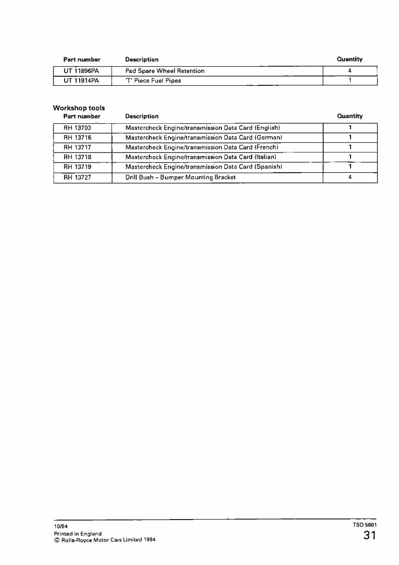
Workshop tools Part number
RH 13703
RH 13716
RH 13717
RH 13718
RH 13719
RH 13727
10/94 Printed in England
Description
Pad Spare Wheel Retention
T Piece Fuel Pipes
Description
Mastercheck Engine/transmission Data Card (English)
Mastercheck Engine/transmission Data Card (German)
Mastercheck Engine/transmission Data Card (French)
Mastercheck Engine/transmission Data Card {Italian)
Mastercheck Engine/transmission Data Card (Spanish)
Drill Bush - Bumper Mounting Bracket
© Rolls-Royce Motor Cars Limited 1994
Quantity
I 4
I 1
Quantity
1
1
1
1
1
4
TS05601
31

Transmission Control Module (TCM) model year cars, the feeds came from the boost control module which has now been deleted. A new transmission control module (TCM} has been
fitted (Part No. NT 10104). The installation is very similar to 1994 model year.
3. The Shift Energy Management signal is now a pulse-width modulated signal which controls the amount of power reduction required for each gear shift.
The main alteration being a single multi-pin connector which replaces the two previous connectors, thus resulting in pin-out number changes (see chart below).
4. The brake signal has changed on the TCM. The colour of the brake signal cable remains green/light green (GLGI at the TCM connector, but it is now spliced into the green/brown (GN} signal line from the stop lamps switch. The 'off' side of the stop lamps switch is now not connected. This GN signal also connects to the ECM (pin 35), the ABS control module (pin 25}, and the ARC control module. The signal from this cable is as follows, 1 volt - brake off; battery voltage - brake on.
The 1994 model year wiring diagrams for the TCM may still be used to diagnose faults on the vehicle.
Additional changes 1. The input and output shaft speed sensors are now 2-core screened cables, whereas 1994 model year were single core screened. 2. The TCM supplies a 5 volt feed and signal ground to the boost pressure transducer. On 1994
The following inputs/outputs from the TCM have been deleted; AS - Diagnostics switch, C2 - Ground, C7 - Parameter code.
New pin 94 MY pin Description Cable
2 83 Air conditioning compressor signal 0.5 UY
3 A3 PSM X - Mode A switch 0.5 OLG
4 AS PSM Z - Mode C switch 0.5 OU
5 A2 Mode change switch- Sport 0.5GB
6 C6 Parameter code switch 0.5WO
7 A10 Shift energy management signal - To ECM 0.5YS
12 B1 Acknowledge shift signal - From ECM O.SYK
14 C3 Sensor ground - Barometer, boost and throttle potentiometer 0.580
15 D14 Barometer sensor signal 0.5 GO
16 D12 Diagnostics line 'L' 0.5 LGR
17 C4 Sensor supply (+5V) - Barometer, boost and throttle 0.5 PO potentiometer
18 - Output speed sensor screen 0.5W
19 - Input speed sensor screen 0.5W
21 B2 Check engine - signal input 0.5 GY
22 A4 PSM Y- Mode B switch 0.50N
23 A1 Mode change switch - Manual 0.508
25 B4 Brake switch 0.5 GLG
26 D13 Transmission temperature sensor 0.50G
30 D5 Engine speed - From ECM 0.5WB
31 D10 Throttle position potentiometer 0.5RO
34 D1 Road speed signal output to cruise control 0.5 RP
35 DB Boost pressure transducer 0.5 GP
36 B11 Output speed sensor - High 0.5 U
37 D4 Input speed sensor - High 0.5 U
39 A7 Shift solenoid A 0.50Y
40 89 Check transmission - signal output 0.5 LGO
41 B6 Sport mode lamp 0.5SG
42 85 TCC solenoid 0.50W
10/94 TSD5601 Printed in England © Rolls-Royce Motor Cars Limited 1994 33

New pin 94MYpin Description Cable
43 AS Shift solenoid B 0.50S
44 87 Manual mode lamp 0.5SO
45 B10 Diagnostics line K 0.5 LGS
49 C15 Force motor - Low O.SOP
50 D3 Input speed sensor - Low 0.5 N
51 812 Output speed sensor - Low 0.5 N
52 D16 Force motor - High 0.50R
53 C16 Ignition supply 1.0KO
54 c, Ground 1.0 BK
55 A12 Battery supply 0.5 NO
10/94
34