rolling stock manual - queensland pioneer … stock manual 2012 safety management system chapter 6...
TRANSCRIPT

Safety Management System Chapter 6 Ver 12 rev 0
Queensland Pioneer Steam Railway
Page 1 of 71
ROLLING STOCK MANUAL
2012

Safety Management System Chapter 6 Ver 12 rev 0
Queensland Pioneer Steam Railway
Page 2 of 71
Table Of Revisions
Orignal Issue August 2012 Legend
QPSR Queesland Pioneer Steam Railway QR Queensland Rail Ltd QT Rail Safety Accrediation Unit Queensland Transport QRNational QR NATIONAL
Issued for the use of The Locomotive and Rollingstock
Supervisor and Delagates All personel who effect repairs must First be sanctioned by
the Supervisor This Manual covers all Rollingstock on QPSR
DIESEL ELECTRIC LOCOMOTIVES ARE COVERED IN EMD MAINTAINANCE MANUAL
(QR)
ALL INSPECTIONS AND REPORTS SHALL BE COMPLIED ON FORM 1 EXCEPT FOR SINGLE CAR TEST

Safety Management System Chapter 6 Ver 12 rev 0
Queensland Pioneer Steam Railway
Page 3 of 71
TABLE OF CONTENTS
1.0 DESCRIPTION OF CARRIAGES ............................................................ 8
1.1. MISCELLANEOUS TYPES .................................................................................................. 8
1.2 CARRIAGE BOGIES .............................................................................................................. 8
1.2.1 intentionally left blank ...................................................................................................... 9
1.2.2 Pressed Steel Bogies .......................................................................................................... 9
1.2.3 New Zealand Bogies .......................................................................................................... 9
1.2.4 Plate Frame Bogie ............................................................................................................ 9
1.2.5 Angle Iron Bogie ............................................................................................................... 9
1.2.6 Extended Angle Iron Bogie.............................................................................................. 10
1.2.7 Carriage Bar Frame Bogie .............................................................................................. 10
1.2.8 Welded Fabricated Bogie ................................................................................................. 10
1.2.9 Cast Steel Bogie .............................................................................................................. 10
1.2.10 Road Railer Bogie…………………………………………………………………………9
2 WAGON BOGIES ...................................................................................... 11
2.1 TYPES OF BOGIES .............................................................................................................. 11
2.1.1 Cast Steel Bogies ............................................................................................................. 11
2.2 CAST STEEL BOGIE BRAKE EQUIPMENT .................................................................... 12
2.3 BAR FRAME BOGIE ........................................................................................................... 13
2.5 BOGIE CENTRE PIVOTS ................................................................................................... 13
2.6 BOGIE SIDE BEARERS....................................................................................................... 14
3 WHEELS AND AXLES .............................................................................. 15
3.1 WHEEL FLANGE WEAR .................................................................................................... 15
3.2 CHECKING CONDEMNED FLANGE GAUGE. ............................................................... 16
3.3 WHEEL TREAD WEAR. ..................................................................................................... 16
3.4 ILLUSTRATIONS OF WHEEL WEAR .............................................................................. 18
3.5 CONDEMNED RIM OR TYRE THICKNESS .................................................................... 19
3.6 LOOSE WHEELS AND TYRES ......................................................................................... 19
3.7 FLAT OR SKIDDED WHEELS ........................................................................................... 19
3.8 OVERHEATED WHEELS ................................................................................................... 20
3.9 WHEEL DEFECTS ............................................................................................................ 20
3.10 BENT AXLES ...................................................................................................................... 20
Safety Management System Chapter 6 Ver 12 rev 0
Queensland Pioneer Steam Railway
Page 4 of 71
3.11 FOULING OF AXLES ........................................................................................................ 20
4.0 AXLEBOXES .......................................................................................... 21
4.1 Grease Lubrication Of Roller Bearing Axleboxes. ............................................................... 22
4.1.1 Passenger Vehicles ......................................................................................................... 22
4.1.2 Wagons ........................................................................................................................... 22
4.2 BOXES HAVING WOOL WASTE PACKING ................................................................... 22
4.3 HOT AXLEBOXES ............................................................................................................... 23
4.4 BEARING SLOG ................................................................................................................... 23
5.0 BUFFERS .............................................................................................. 24
5.1 STEM BUFFERS ................................................................................................................... 24
5.2 SELF CONTAINED BUFFERS ............................................................................................ 24
5.2.1 Fitting Of Self Contained Buffers .................................................................................... 24
5.3 COMPENSATING ARRANGEMENT ................................................................................ 24
5.4 CROWNED BUFFERS ......................................................................................................... 25
5.6 BUFFER DIMENSIONS ....................................................................................................... 26
5.6.1 Buffer Head Size ............................................................................................................. 26
5.6.2 Distance From Headstock ................................................................................................ 26
5.6.3 Buffer Height .................................................................................................................. 26
5.7 DEFECTIVE BUFFERS ...........................................................................................................
6. DRAWGEAR ........................................................................................................................... 27
6.1 TYPES OF AUTOMATIC COUPLERS .............................................................................. 27
6.2 INSPECTION OF AUTOMATIC COUPLERS. .................................................................. 27
6.2.1 General Inspection Of Couplers ...................................................................................... 27
6.2.2 Locking Mechanism ....................................................................................................... 27
6.2.3 Knuckle .......................................................................................................................... 28
6.2.4 Transition Coupling ........................................................................................................ 28
6.2.5. Coupler Shank ................................................................................................................ 30
6.2.6 Carrier Wear Plate ........................................................................................................... 31
6.2.7 Lubrication ...................................................................................................................... 31
6.3 COUPLING AND UNCOUPLING PROCEDURE AUTOMATIC COUPLERS .............. 31
6.3.1 Coupling Procedure ........................................................................................................ 31
6.3.2 Possible Cause of Coupler Not Locking ........................................................................... 31
6.3.3 Coupling Force ................................................................................................................ 32
6.3.4 Uncoupling Procedure ..................................................................................................... 32
6.3.5 Uncoupling Procedure ..................................................................................................... 35
6.3.6 To check that a coupler is properly locked ....................................................................... 35
6.3.7 TRANSITION COUPLINGS .......................................................................................... 35
6.3.8 Coupling Procedure with Transition Couplings ................................................................ 35
6.3.9 Longitudinal Slack Of Automatic Coupler And Draft Gear .............................................. 36

Safety Management System Chapter 6 Ver 12 rev 0
Queensland Pioneer Steam Railway
Page 5 of 71
6.3.10 Standard Drawgear ........................................................................................................ 37
6.3.11 Non Continuous Drawgear ............................................................................................. 37
6.3.12 Standard Distance Of Drawhook From Headstock. ........................................................ 37
6.3.13 Longitudinal Slack In Standard Drawgear ...................................................................... 37
6.3.14 Screw Couplings ............................................................................................................ 37
7 STANDARD MARKINGS ON CARRIAGES AND WAGONS .................... 38
7.1 WAGON MARKINGS .......................................................................................................... 38
7.1.1 Wagon Class And Number .............................................................................................. 38
7.1.2 Wagon Mass .................................................................................................................... 38
7.1.3 Size Of Wheel Journal ..................................................................................................... 38
7.1.4 Lifting And Oiling Block ................................................................................................. 38
7.1.5 Lifting And Greasing Date Block .................................................................................... 39
7.1.6 Painting Date ................................................................................................................... 39
7.1.7 Air Brake Attention Date Blocks ..................................................................................... 39
7.1.8 Wagons With No Brake Gear .......................................................................................... 39
7.1.9 Unit Length ..................................................................................................................... 40
7.1.10 Drawgear Classification ................................................................................................. 40
7.2 CARRIAGE MARKINGS ..................................................................................................... 40
7.2.1 Carriage And Number...................................................................................................... 40
7.2.2 Carriage Tare Weight ...................................................................................................... 40
7.2.3 Lifting And Oiling Date Block......................................................................................... 40
7.2.4 Lifting And Greasing Block ............................................................................................. 41
7.2.5 Painting Date ................................................................................................................... 41
7.2.6 Air Brake Attention Date Blocks ..................................................................................... 41
7.2.7 Unit Length ..................................................................................................................... 41
7.2.8 Drawgear Classification ................................................................................................... 41
7.2.9 Water Tank Cock ............................................................................................................. 41
8. CARRIAGE MISCELLANEOUS EQUIPMENT ......................................... 42
8.1 WATER RAISING UNITS.................................................................................................... 42
8.2 PASSENGER INTERCOMMUNICATION GEAR ............................................................ 42
9. GENERAL ................................................................................................ 43
9.1 ADJUSTMENT AND OILING OF HAND BRAKES ON CARRIAGES AND VANS ...... 43
9.2 REMOVAL OF SPRAGS AND CHOCKS FROM WHEELS ............................................ 43
9.3 MARKING OFF ROLLINGSTOCK FOR REPAIRS ......................................................... 43
9.4 EMERGENCY COUPLING LINKS .................................................................................... 43
9.5 FAILURE OF DRAWGEAR ON VEHICLES ..................................................................... 43
9.6 DEFECTIVE COUPLINGS .................................................................................................. 44
9.7 HAND BRAKES AND AIR BRAKES ON HOPPER WAGONS ........................................ 44

Safety Management System Chapter 6 Ver 12 rev 0
Queensland Pioneer Steam Railway
Page 6 of 71
10. AIR BRAKE SYSTEM- CARRIAGE AND WAGON ................................ 45
10.1 GENERAL DESCRIPTION ................................................................................................ 45
10.2 CARRIAGE AND WAGON BRAKE EQUIPMENT .............................................................. 47
10.2.1 Functions Of The Triple Valve ...................................................................................... 48
10.2.2 A General Description Of The Four Types Of Triple Valves. ......................................... 48
10.2.3 Auxiliary Reservoirs ...................................................................................................... 51
10.2.4 Brake Cylinders ............................................................................................................. 52
10.2.5 Brake Rigging ............................................................................................................... 53
10.2.6 Hand Release Valve ....................................................................................................... 54
10.2.7 Triple Valve Isolating Cock ........................................................................................... 54
10.2.8 Type “J” Automatic Slack Adjuster ............................................................................... 55
10.2.9 Brake Pipe Coupling Cocks ........................................................................................... 55
10.2.10 Brake Pipe and Hose Coupling Pipes. .......................................................................... 56
10.2.11 Centrifugal Dirt Collectors. ...................................................................................... 57
10.3 PERMISSIBLE PISTON TRAVELS .................................................................................. 57
10.4 ADJUSTMENT OF BRAKES ............................................................................................. 58
10.5 METHOD OF ADJUSTING HANDBRAKES ON WAGONS .......................................... 59
10.6 Passenger Cars and Brake Vans.......................................................................................... 61
10. 7 Wagons ............................................................................................................................... 61
10.8 TRAIN REQUIREMENTS FOR VEHICLES HAVING BRAKES CUT OUT ............... 63
10.9 PROCEDURE FOR CUTTING-OUT BRAKES ............................................................... 63
10.10 ISSUE OF SPECIAL AUTHORITYS. ................................................................................ 63
10.10.01 MOVEMENT Of SELDOM USED VEHICLES
11. BRAKE EQUIPMENT DEFECTS AND TROUBLE SHOOTING ............. 64
12.1 CHECK ALL READILY OBSERVABLE BOLTS AND NUTS ON THE GENERATOR AND OTHER
COMPONENTS FOR TIGHTNESS .......................................................................................... 66
12.2 HOW TO CHECK THE FREEDOM OF MOVEMENT OF THE GENERATOR ON THE
SUSPENSION PIN, INCLUDING LUBRICATION OF THE SUSPENSION PIN AND ADJUSTING
SCREWS ...................................................................................................................................... 66
12.3 HOW TO CHECK THE WIRING FOR ABRASION AND THE METHOD OF MAKING
TEMPORARY REPAIRS ........................................................................................................... 66
12.4 HOW TO CHECK THE BATTERIES FOR LEAKAGE OF ACID ............................... 66
12.5 HOW TO REPLACE A FUSE, AND THE CORRECT SIZES AND TYPES TO BE USED IN THE
BATTERY AND LIGHTING CIRCUITS RESPECTIVELY. .................................................. 67
12.6 REPLACEMENT OF FLUORESCENT TUBES IN VANS ............................................. 67

Safety Management System Chapter 6 Ver 12 rev 0
Queensland Pioneer Steam Railway
Page 7 of 71
13 IMPORTANT DIMENSIONS FOR CARRIAGE AND WAGONS COMPONENTS ...................................................................................................................... 68
13.1 WHEELS ............................................................................................................................. 68
13.2 BUFFERS ............................................................................................................................. 68
13.3 DRAWGEAR ....................................................................................................................... 68
13.4 STANDARD LOADING DIAGRAM ................................................................................. 68
13.5 RAIL CLEARANCE ........................................................................................................... 68

QUEENSLAND PIONEER STEAM RAILWAY
Page 8 of 71
1.0 Description of Carriages
There are many types of carriages in service and it would not be possible within the scope of this document to describe in detail all types. The various types of carriages in use are generally described under; Not all these are at present at QPSR however they could be present in the future.
(1) SITTING CARS (2) MISCELLANEOUS CARS (3) BRAKE VANS and BAGGAGE CARS.
Carriage stock is fitted with electric lighting, the power being supplied by an axle driven dynamo or alternator, with storage batteries being fitted to supply power when the carriages are standing. Some carriages have had the generator / Alternator removed.And some cars a wired for AC generation of power.On QPSR these Dynamo have had the belt removed and some dynamo are also removed.
1.1. MISCELLANEOUS TYPES
These include special purpose cars, together with other types of cars not included in the above classifications. Special purpose cars and wagons include inspection cars, and instruction cars, i.e. Camp Wagons. Eg: AL773 Prision Car Some of these cars and camp wagons are adapted for connection to external power. Some of these cars including camp wagons have bogies and under frame equipment similar to passenger carriages whilst others are not permitted to operate in passenger trains.
1.2 CARRIAGE BOGIES
The following types of bogie are to be found under the various classes of carriage stock some are not At QPSR however they are used in Queensland and may at some time be at QPSR. (ii) Pressed Steel (iii) New Zealand (iv) Plate Frame (v) Angle Iron (vi) Extended Angle Iron (vii) Carriage Bar Frame (viii) Weld Fabrication (ix) Cast Steel

QUEENSLAND PIONEER STEAM RAILWAY
Page 9 of 71
1.2.1 Intentionally left blank
1.2.2 Pressed Steel Bogies
This type of bogie is easily recognised by the fact that its side frames are pressed from plate steel. Bogies of the type are fitted to the majority of carriage stock, especially the heavier type. The distance between wheel centre is 1 753mm and springing is carried out by triple elliptic springs at the bolster and semi-elliptic at the side frame above the axleboxes. The bogies are fitted with 915mm diameter wheels and 8 inch X 4 inch journal axles. The size of springs used with these bogies depends upon the tare weight of the carriage to which the bogies are fitted. Bogies on some coaches are fitted with SKF or Timken type roller bearings. A number of the pressed steel bogies are fitted with coil type bolster springs in place of the triple elliptic springs. These are call "Fox's" bogies and have 1 676 mm between wheel centres. Some pressed steel bogies are fitted with clasp brakes. Journal bearing lubrication is by means of wool waste packing and oil for plain brass bearings and for roller bearings grease lubrication is applied.
1.2.3 New Zealand Bogies
Only a few carriages are fitted with this type of bogie. these bogies are of bar construction fitted with spring beams which take two coil springs, each side under the frame. The bolster is supported on elliptic springs. The journals are 8"X4" with either 851mm dor 660 mm diameter wheels. Journal bearing lubrication is by means of wool waste packing and oil. Very similar to Pressed Metal Bogies This section is included for information.
1.2.4 Plate Frame Bogie
These bogies distinguished by their plate construction, having 22 mm thick side frame plates. Wheels are 850 mm or 660mm diameter with 8" X 4" journals. The wheel spacing is 1 829 mm and a steel bolster is fitted. Springing is by a cluster of three coil springs on each side of the bolster and by side bearing springs. Lubrication of the Journal bearing is by wool waste packing and oil. This section is included for information.
1.2.5 Angle Iron Bogie
As the name implies, the frames are made from angle iron. The wheels fitted to these bogies are 660 mm diameter with 7" X 3" journals. The springing is carried out by laminated side bearing springs and double elliptic springs under the bolster. These bogies are used under the lighter type of carriages. journal bearing lubrication is by wool waste packing and oil.
QUEENSLAND PIONEER STEAM RAILWAY
Page 10 of 71
1.2.6 Extended Angle Iron Bogie
These bogies are generally similar to the angle iron bogie described above. They are provided with an extended angle iron portion at the side to give a longer bolster and wider spacing of the side bearers. The springing is carried out by laminated side bearing springs, and double or triple elliptic springs under bolster as required. They are fitted with 660 mm diameter wheels and 7" X 3" journals. Journal bearing lubrication is by wool waste packing and oil.
1.2.7 Carriage Bar Frame Bogie
These bogies, which are also used under the lighter type carriages, have various diameter wheels and 7" X 3" journals. they are formed by using bar material and can be distinguished by the fact that the axlebox bearing springs are directly above the bar frame supported on the axlebox by the saddle. some are fitted with a compensating bar between the springs. Journal bearing lubrication is by wool waste packing and oil.
1.2.8 Welded Fabricated Bogie
TGVS vans are fitted with a welded fabricated plate bogie having a wheel base of 1,829 mm. wheels are 762 mm diameter and are equipped with roller bearings. This section is included for information.
1.2.9 Cast Steel Bogie
A small number of carriages such as BBV Class Wooden Vans are fitted with cast steel freight type bogies (e.g.QR 1, QR12, QR4, QR14/17/20 etc. bogies). But not confined to these types. These types of bogie will be discussed in Chapter 2
1.2.10 Road Railer Bogie
There are two examples of these at QPSR. They are three piece bogies fitted for use under Road Trailers when transported by rail. Numbers RRY 45874 & RRY 45872. These will be covered more fully in a later publication on bogie types. At Present only used for Storage of Queensland Diesel Restoration Group Assets

QUEENSLAND PIONEER STEAM RAILWAY
Page 11 of 71
2 WAGON BOGIES
2.1 TYPES OF BOGIES
The following types of bogies are to be found under the various classes of wagons:- (i) Pressed steel (ii) Angle Iron (iii) Extended angle iron (iv) Cast Steel (v) Bar frame (vi) Plate frame (vii) Road Railer ( covered in a special section) a brief description of each type is as follows:- The pressed steel, angle iron and extended angle iron are carriage bogies and are described chapter 1
2.1.1 Cast Steel Bogies
Figure 2-1 Identification of Bogie Parts
The cast steel bogies, of which there are a number of types, consist of three main members, i.e. the bolster and two side frames as shown in Figure 2-1. The different types of Cast Steel bogie will be shown in Appendix 1 The Side frames sit directly on top of the axleboxes or package bearings and tie the two wheelsets together longitudinally.

QUEENSLAND PIONEER STEAM RAILWAY
Page 12 of 71
The Bolster spans between the two sideframes, each end resting on a group of springs which provides vertical and some lateral flexibility. Stops on the bolster termed Gibs limit lateral movement when in contact with sideframe column. The Coil Springs are positioned in clusters under the bolster ends The movement of the bolster relative to the sideframe is dampened by means of two Friction Wedges or Shoes (snubbers). Under no circumstances must the wearing surfaces of the friction wedges or shoes be lubricated. Friction shoes have a condemning groove in the top surface and should be replaced when wear reaches that point. A top Centre Casting on the vehicle body rests on a recessed centre plate in the bolster, its rim preventing longitudinal or lateral relative movement. A Centre Pin (King Pin) passes through the top centre casting of the wagon and the bogie bolster as a safety feature. Cotters at the top and bottom of the centre pin limit the vertical separation of the bolster from the wagon to between 6 and 9 mm.
2.2 CAST STEEL BOGIE BRAKE EQUIPMENT
The axlebox is an integral part of some of the bogie side frames. All of these earlier type bogies have subsequently been fitted with roller bearing wheelsets. These wheelsets were fitted with "Package" roller bearing units and in order to fit the wheelsets and axlebox section of the bogie side frame was cut away to allow re-fabrication. Only package bearing wheelsets can be used in these bogies . The roller bearing wheelsets are of two types:- (a) Those fitted with conventional axleboxes, i.e. generally rectangular with wear faces that slide in the bogie side frame wear faces. (b) Those fitted with package bearing units. These units are usually circular in shape and in order to apply then to the bogies, an adaptor is necessary. The adaptor is a S.G. Iron Casting shaped on the bottom to fit the package bearing and on the top with flat surface to bear on the bogie side frames axlebox section. The adaptor shall remain with the bogie when wheelsets are changed. The majority of cast steel bogies are fitted with roller bearing wheelsets with conventional axleboxes, but it is possible to use package bearing wheelsets by the use of suitable adaptors. These adaptors are shaped on the ends to slide in the bogie side frame axlebox section wear faces. The following example illustrates a number of varying combinations of bogie, roller bearing wheelset/package bearing wheelsets:- A BLV van could be fitted with:-

QUEENSLAND PIONEER STEAM RAILWAY
Page 13 of 71
(A) QR4 bogies converted for package bearings and with 660 mm package bearing wheelsets and adaptors or (B) QR17, 20 or 24 bogies fitted with conventional roller bearing axlebox wheelsets or (C) QR17 20 or 24 bogies fitted with 660 mm package bearing wheelsets and adaptors Roller bearing axleboxes and package bearing units are grease lubricated.
2.3 BAR FRAME BOGIE
There is a number of types of bar frame bogies in service, all however, are similar in basic design. The framework of the bogie is mild steel bar and the size of the top bar specifies the common name of the bogie, i.e. (3" X 1") bar frame, (4" X 1") bar frame and (4 X 1 1/4") bar frame. A fabricated steel bolster carrying the bogie centre casting and side bearers is positioned above a spring plank carrying the bolster spring nests. In some of the (3" X 1") bar frame bogies, the bolster and transoms are wooden as is the spring plank. The bogie axleboxes are mounted between the bogie frame's top and bottom bars by means of two bolts, one on either side of the axlebox. In comparison with the cast steel bogie, the bar frame bogie has many more hangers and attachments to the frame, i.e. 4 bolster swing links 4 brake beam safety loops, 4 brake block hangers and 2 bolster safety straps, apart from the brake arrangement mechanism. The wheelsets and axleboxes used in bar frame bogies include 8" X 4" X 660 mm and 7" X 3" x26" (660 mm) and 8" X 4" X 33 1/2" (850 mm) wheelsets. Very few 7" X 3" X 33 1/2" (850 mm) wheelsets are now in existence in bar frame bogies. Axle journal lubrication is by means of wool waste packing and oil.
2.5 BOGIE CENTRE PIVOTS
A Top Centre Casting on the vehicle body rests on a recessed Centre Plate in the bolster, its rim preventing longitudinal or lateral relative movement. On some wagons a centre plate liner is placed between the top centre casting and centre plate as shown in Figure 2.2. A Centre Pin (King Pin) passes through the top centre casting of the wagon and the bogie bolster as a safety feature. Cotters at the top and bottom of the centre pin limit the vertical separation of the bolster from the wagon to between 6 and 9 mm.

QUEENSLAND PIONEER STEAM RAILWAY
Page 14 of 71
Figure 2.2
2.6 BOGIE SIDE BEARERS
Since the centre casting is only approximately 350 mm in diameter, it cannot prevent roll of the wagon with to the bolster. Side bearers at 940 mm centres are used to limit this movement. The most common arrangement consists of a wear plate on the bogie bolster contacting a bracket bolted to wagon underframe as shown below The clearance is set to between 6.5 and 8 mm using shims. side bearer clearance should be checked by measuring the side bearer clearance on each side of a bogie bolster and then averaging these measurements.
Figure 2.3

QUEENSLAND PIONEER STEAM RAILWAY
Page 15 of 71
Constant Contact Side Bearers are used on later wagons and these consist of a spring element (Resilient block) providing a controlled preload force between the bolster and the wagon under frame as shown in Figure 2.4. They assist in controlling the roll of the wagon and more importantly provide a controlled friction force assisting the tracking of the bogie.
Figure 2.4
3 WHEELS AND AXLES One of the duties of a Train examiner is to keep a watch for wheel flange wear, tread and loose tyres and to make a check on the general condition of the wheel set.
3.1 WHEEL FLANGE WEAR
To check that the wheel flanges are still within working limit a condemned flange Gauge G320 may be used, a drawing of which is illustrated in figure 3.1a. In use, the Condemned Flange Gauge must be held square to the inside face of the wheel or parallel to the axle. A wheel flange is condemned when- (a) The bottom of the gauge contacts the thread of the tyre, or (b) the gauge contacts the top of the flange. As flange wear is progressive, Train Examiners may indicate the condition of flanges checked, by chalking the following standard markings on the solebar or bogie side frame as necessary.

QUEENSLAND PIONEER STEAM RAILWAY
Page 16 of 71
Some wear evident Flange wear approaching condemning stage, but still satisfactory to run Condemned flange. When a wheel flange is condemned the vehicle should be marked for shop attention.
3.2 CHECKING CONDEMNED FLANGE GAUGE. ( if used)
In order to check that the Condemned Flange Gauge G320 is still within tolerance, (i.e. not worn), a Wear Limit Gauge for wheel Flange Condemning Gauge" G273 should be used. Any lateral play between gauges indicate wear in excess of 0.2mm and condemned flange gauge should be withdrawn from use.
3.3 WHEEL TREAD WEAR.
The maximum allowable tread wear has been laid down at 5mm. This can be determined by use of gauges or by measuring (by means of a straight edge across the top of the two flanges). When the flange depth has reached 33mm, the wheelset is to be withdrawn from service. There is one (1) type of gauge provided to check tread for wear viz G320. Gauge G320 may be used by holding it square on the inside face of the wheel or parallel to the axle. The wheel set is condemned when the gauge contacts the top of the flange. The gauge may be checked once every 12 months.

QUEENSLAND PIONEER STEAM RAILWAY
Page 17 of 71
Figure 3.1

QUEENSLAND PIONEER STEAM RAILWAY
Page 18 of 71
3.4 ILLUSTRATIONS OF WHEEL WEAR
(a) EDGE ROLLOVER The maximum allowable edge rollover is 10mm. This is measured from the vertical outside face of the wheel as shown below.
Figure 3.2
A square sharp corner occasionally develops on the periphery of a flange. When this condition is observed , the wheel is to receive repair attention by grinding off the sharp edge or by replacement of the wheelset.
10 mm

QUEENSLAND PIONEER STEAM RAILWAY
Page 19 of 71
3.5 CONDEMNED RIM OR TYRE THICKNESS
The condemned limits for rim or tyre thickness for carriages and wagons are as tabled below:-
Type of Wheel Condemned Rim or Tyre Thickness (mm)
915 mm Tyred wheel 20
850mm Tyred wheel 20
840mm Tyred wheel 20
660mm Tyred wheel 20
915mm Tyred wheel 20
850mm Tyred wheel (up to 12 TAL)
20
850mm Solid wheel (up to 12 TAL)
17
760 mm Solid wheel 17
660mm Solid wheel 17
3.6 LOOSE WHEELS AND TYRES
Loose tyres can be determined if, when the tyre is struck with a hammer, it gives out a dull sound. Also if the movement between the tyre and wheel centre can be observed which forms a crack in the oil or/and dirt accumulation at these junction points, or by a dust line at these junctions. A rusty dust marking is a sure sign of loosening. Tyres are fitted to some solid wheels as well as spoke wheels. A loose wheel can be determined either by an increase or decrease in the distance between wheels in a wheelset or between the axlebox and wheel boss; also by a movement line formed at the junction of the axles and wheel centre.
3.7 FLAT OR SKIDDED WHEELS
Flats and build up of metal can develop on the tyre treads and are caused by wheel skidding. If theses are severe the wheel should be removed for attention. Small flats can be eased off by grinding, if suitable equipment is available, and build up of metal can be chipped or ground off in some instances. Cast iron grooved cutter blocks can be used to advantage in removing metal build up in service and to remove small flats on wheels. Where a severe flat or large metal build up has occurred the matter shall be bought to the attention of the fitter / examiner. Every effort should be made to determine the cause of the flat or metal build up. Typical causes are the handbrake being left on, or a defect in the brake equipment.

QUEENSLAND PIONEER STEAM RAILWAY
Page 20 of 71
3.8 OVERHEATED WHEELS
Some wheels are coated with a temperature indicating paint. This paint is grey in colour and will blister and discolour at approximately 300o C. Overheated wheels are defined as those showing blistering of the temperature indicating coating on the web of the wheel below the rim. When a wheel has been found to have overheated, the wagon shall be marked off for wheel attention. Every effort should be made to determine the cause of the overheating. Typical causes are the handbrake being left on, or a defect in the brake equipment. The above shall be brought to the attention of the Rolling Stock Supervisor using reporting form.
3.9 WHEEL DEFECTS
A sharp lookout should be kept for any wheel which shows evidence of having a defect, flaw or crack which would cause the wheels to fail in service. if any are found they shall be brought to the attention of the Rolling Stock Supervisor using the reporting form. Form 1
3.10 BENT AXLES
If there is any evidence of a bent axle, this can be checked by using distance trammels between the inside of the tyres. The distance is to be compared at four (4) positions 90 degrees apart. This distance should be 990 - 992 mm. A badly bent axle can also be detected if the vehicle is moved slowly and the position of the flanges is checked relative to the rail. Abnormal movement of an axlebox in a bogie during the movement of the vehicle will indicate a bent axle.
3.11 FOULING OF AXLES
A watch should also be kept for any fouling of the axle by brake gear or any other rod or dropped part. A brake rod rubbing on an axle can cause severe grooving and may ultimately cause failure of the axle or brake failure.

QUEENSLAND PIONEER STEAM RAILWAY
Page 21 of 71
4.0 AXLEBOXES
There are three (3) general types of axleboxes used by the society as illustrated below in the Figures 4.1 to 4.3. The use of these types of axleboxes was discussed in a previous section
Figure 4.1 - Figure 4.3
4
QUEENSLAND PIONEER STEAM RAILWAY
Page 22 of 71
4.1 Grease Lubrication Of Roller Bearing Axleboxes.
The periodic lubrication of roller bearings is to be carried out at the following intervals:-
4.1.1 Passenger Vehicles
(a) After wheel turning or renewal These are now qualified as No Field Lubrication (NFL )
4.1.2 Wagons
(a) After wheel turning or renewal of solid wheels,- 1. Conventional roller bearing Axleboxes 2. Package Bearing Roller Units
All these are now Qualified as NO FIELD LUBRICATION (NFL)
4.2 BOXES HAVING WOOL WASTE PACKING
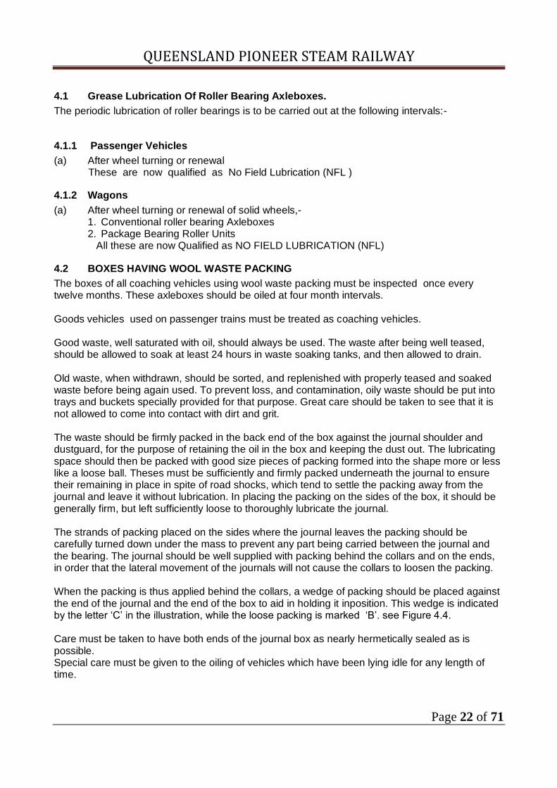
The boxes of all coaching vehicles using wool waste packing must be inspected once every twelve months. These axleboxes should be oiled at four month intervals. Goods vehicles used on passenger trains must be treated as coaching vehicles. Good waste, well saturated with oil, should always be used. The waste after being well teased, should be allowed to soak at least 24 hours in waste soaking tanks, and then allowed to drain. Old waste, when withdrawn, should be sorted, and replenished with properly teased and soaked waste before being again used. To prevent loss, and contamination, oily waste should be put into trays and buckets specially provided for that purpose. Great care should be taken to see that it is not allowed to come into contact with dirt and grit. The waste should be firmly packed in the back end of the box against the journal shoulder and dustguard, for the purpose of retaining the oil in the box and keeping the dust out. The lubricating space should then be packed with good size pieces of packing formed into the shape more or less like a loose ball. Theses must be sufficiently and firmly packed underneath the journal to ensure their remaining in place in spite of road shocks, which tend to settle the packing away from the journal and leave it without lubrication. In placing the packing on the sides of the box, it should be generally firm, but left sufficiently loose to thoroughly lubricate the journal. The strands of packing placed on the sides where the journal leaves the packing should be carefully turned down under the mass to prevent any part being carried between the journal and the bearing. The journal should be well supplied with packing behind the collars and on the ends, in order that the lateral movement of the journals will not cause the collars to loosen the packing. When the packing is thus applied behind the collars, a wedge of packing should be placed against the end of the journal and the end of the box to aid in holding it inposition. This wedge is indicated by the letter ‘C’ in the illustration, while the loose packing is marked ‘B’. see Figure 4.4. Care must be taken to have both ends of the journal box as nearly hermetically sealed as is possible. Special care must be given to the oiling of vehicles which have been lying idle for any length of time.
QUEENSLAND PIONEER STEAM RAILWAY
Page 23 of 71
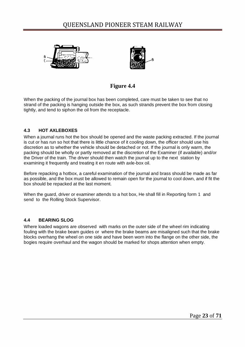
Figure 4.4
When the packing of the journal box has been completed, care must be taken to see that no strand of the packing is hanging outside the box, as such strands prevent the box from closing tightly, and tend to siphon the oil from the receptacle.
4.3 HOT AXLEBOXES
When a journal runs hot the box should be opened and the waste packing extracted. If the journal is cut or has run so hot that there is little chance of it cooling down, the officer should use his discretion as to whether the vehicle should be detached or not. If the journal is only warm, the packing should be wholly or partly removed at the discretion of the Examiner (if available) and/or the Driver of the train. The driver should then watch the journal up to the next station by examining it frequently and treating it en route with axle-box oil. Before repacking a hotbox, a careful examination of the journal and brass should be made as far as possible, and the box must be allowed to remain open for the journal to cool down, and if fit the box should be repacked at the last moment. When the guard, driver or examiner attends to a hot box, He shall fill in Reporting form 1 and send to the Rolling Stock Supervisor.
4.4 BEARING SLOG
Where loaded wagons are observed with marks on the outer side of the wheel rim indicating fouling with the brake beam guides or where the brake beams are misaligned such that the brake blocks overhang the wheel on one side and have been worn into the flange on the other side, the bogies require overhaul and the wagon should be marked for shops attention when empty.

QUEENSLAND PIONEER STEAM RAILWAY
Page 24 of 71
5.0 BUFFERS
Buffers fitted to QPSR carriage and wagon stock are of two (2) types:- (a) Stem (b) Self-contained
5.1 STEM BUFFERS
The stem buffers are of two types and have various size of heads and length stems. One type is the all steel buffer having the head forged integral with the stem whilst the other has a steel stem and cast iron head. Stem buffers run in sockets which are attached to the headstock, the stem being supported by an internal wagon cross member. Springing is by a coil spring fitted over the buffer stem. Some are fitted to vehicles which have a compensating arrangement as mentioned in 5.3.
5.2 SELF CONTAINED BUFFERS
Self contained buffers are of four types, the old steel Turton and the cast steel steam Locomotive type, and round or oval locomotive types. The Turton buffer comprises a steel body having a rectangular base, steel buffer head, a stem, and a spring. A few Turton buffers remain in service.. Mostly on stop blocks. Turton buffers are 480mm and 520 mm from headstock to outside buffer head . The cast steel buffer has a cast steel body or socket and a cast steel head with an integral cylindrical portion which slides inside the socket. A mild steel stem is fitted inside the head. Springing is by either a coil spring or by a variety of head rubbers. This type of buffer comes with a variety of head sizes. Most Likely 300mm and 450mm. The locomotive types are as follows.
(1) Conical type with internal springing (2) Heavy locomotive type as fitted to 1616 with both round and oval faces.
5.2.1 Fitting Of Self Contained Buffers
Self contained buffers should be fitted in pairs, i.e. either two buffers with coil springs or two with rubber cushion units to each end of a vehicle. It is important that the correct head size be used. Vehicles over12 mtr shall be fitted with 450mm head.
5.3 COMPENSATING ARRANGEMENT
Some carriages have the buffers fitted with a compensating arrangement. Each buffer when compensated is fitted to a buffer bracket which are connected with a transverse link. This arrangement allows buffers on adjacent vehicles to always be in contact when passing round curves or crossovers. However due to the extent of repairs of compensating gear as a result of hitups etc., compensating buffers have been removed from many carriages and self contained buffers fitted instead.

QUEENSLAND PIONEER STEAM RAILWAY
Page 25 of 71
5.4 CROWNED BUFFERS
All buffers of later construction and replacements have crowned heads, but many vehicles are still fitted with both crown and flat headed buffers in which case the crowned buffer head is always fitted to the left hand side when facing the headstock.

QUEENSLAND PIONEER STEAM RAILWAY
Page 26 of 71
5.6 BUFFER DIMENSIONS
The amount of movement of vehicles on a curve and the distance from the bogie centre to the headstock, also the length of the vehicle determine the size of the head which the buffers fitted to various vehicles should have. The type of vehicles also determines the head size of the buffer which should be used.
5.6.1 Buffer Head Size
The majority of buffer heads are either 305mm, 381mm, 457mm, or 508mm in diameter.
5.6.2 Distance From Headstock
The nominal distance from the headstock to the outside surface of the buffer is 520mm and all buffers should be adjusted to give this measurement. When fitting buffers, sufficient compression of the spring should be given (usually 13 mm) so that the buffer cannot be rotated by hand.
5.6.3 Buffer Height
Nominal buffer height is 812mm for all stock when the vehicle is fully loaded in a normal condition. The permissible range laid down is :- Maximum 851 mm when unloaded and minimum 762 mm when loaded . These dimensions are measured from top of rail to centre of buffer.
5.7 DEFECTIVE BUFFERS
Examiners should pay particular attention to the condition of buffers and their sockets. The latter should be maintained in a tight condition to prevent excessive play and also to reduce the wear in socket holding bolt holes, especially in wooden headstocks. Particular attention should be given to the washering up and fitting of the cotter and ring fastener on stem buffers. Broken, bent or maladjusted buffers and defective buffer assemblies should be given attention. These can generally be detected by the buffer not being the correct distance outfrom the headstock or the buffer head can be rotated by hand. Buffers should never be allowed to remain in a bent condition. If this condition comes under notice, they should be renewed as soon as possible. Bent buffers are a potential cause of derailments. Special precautions must be taken to ensure that the rear buffers on vans are properly and securely fitted since loose buffers are liable to fall out and cause possible derailment of succeeding trains.
QUEENSLAND PIONEER STEAM RAILWAY
Page 27 of 71
6. DRAWGEAR
Drawgear fitted to QPSR carriage and wagon stock is of two(2) types: (a) Automatic Coupler D1 & D2 1700 class and D4 ( ALY vans)
and (b) Standard Drawgear D2 ( locomotive) D3 steel underframe coaching stock and wagons D4 non continious draft gear fitted vehicles
6.1 TYPES OF AUTOMATIC COUPLERS
All new wagons and carriages, and those of recent years are fitted with automatic couplers.
There are many designs of automatic coupler in use. The designs currently in use by the QPSR is the “Alliance” - Top Operated which is in use on various classes of wagons,
diesel electric locomotives and some brake vans or as on the MALY/T or ALY/T which is the SHARON Type. Also fitted to 1700 class locomotive.
6.2 INSPECTION OF AUTOMATIC COUPLERS.
Train examiners shall inspect all automatic couplers that can be safely accessed during the normal performance of duties.
6.2.1 General Inspection Of Couplers
Any wear of associated component parts other than indicated, which is observed during inspection, should be reported, as such wear may be indicative of some abnormal failure.
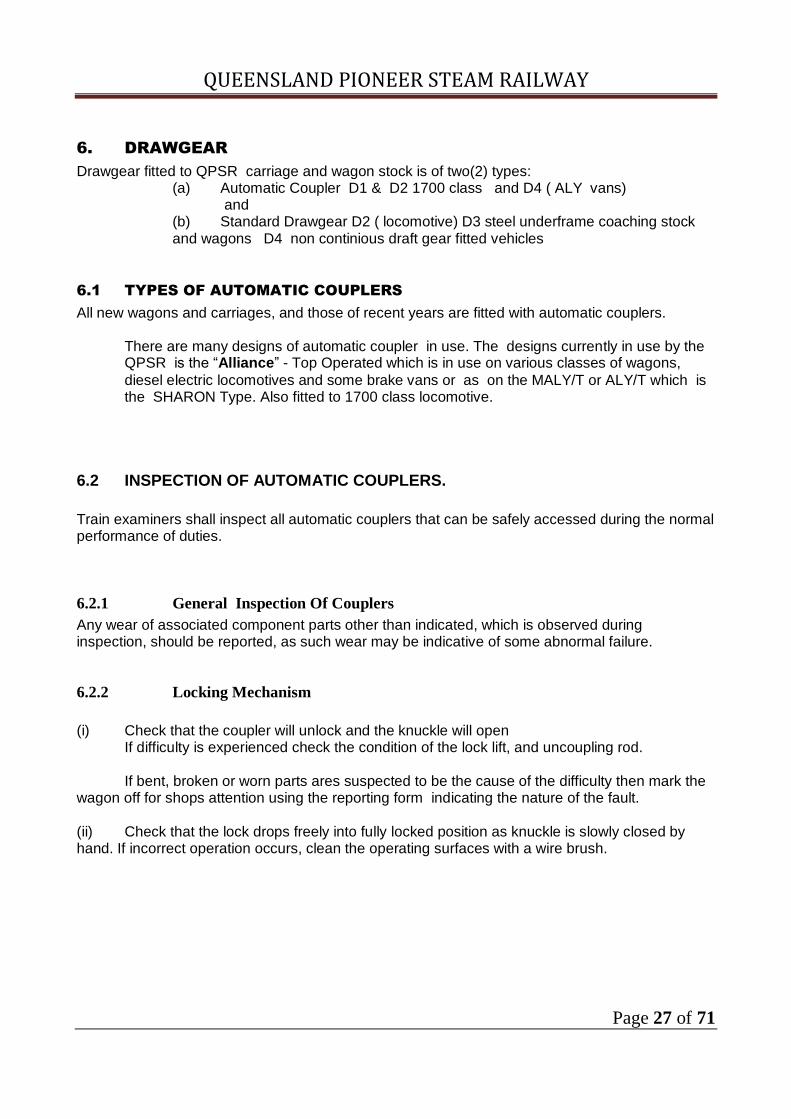
6.2.2 Locking Mechanism
(i) Check that the coupler will unlock and the knuckle will open If difficulty is experienced check the condition of the lock lift, and uncoupling rod. If bent, broken or worn parts ares suspected to be the cause of the difficulty then mark the wagon off for shops attention using the reporting form indicating the nature of the fault. (ii) Check that the lock drops freely into fully locked position as knuckle is slowly closed by hand. If incorrect operation occurs, clean the operating surfaces with a wire brush.

QUEENSLAND PIONEER STEAM RAILWAY
Page 28 of 71
6.2.3 Knuckle
(i) Visually inspect for cracked and broken knuckles. If cracked or broken knuckles are present the wagon shall be marked off for immediate attention. (ii) Inspect for knuckle nose wear. If worn to “wear limit recess” (condemning contour) the wagon must be marked off for attention. (See fig. below). On some knuckles the wear limit is indicated is indicated by a “boss” in lieu of the “recess”. (iii) Check that a split pin in good condition is fitted and spread to all knuckle pivot pins. Replace the split pin if its spread conditon is in doubt or if it is missing.
Figure 6.1
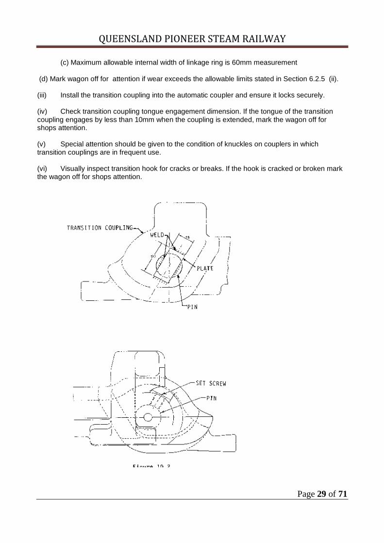
6.2.4 Transition Coupling
(I) Transition couplings use two different method of retaining the coupling pin. Perform an inspection of the retaining mechanism by the method stated as follows: (a) Where the is retained by a mild steel plate. (see fig. 6.2).
Visually check that a plate is fitted and that no cracks are present in the attachment welds. If the attachment welds have broken and the plate is missing OR the attachment welds are cracked, mark the wagon off for attention.
(b) Where the pin is retained by a set-screw only. Visually inspect that a set-screw if fitted to the transition coupling. If the set screw is obviously loose or if it is missing, mark the wagon off for shops attention.
(ii) Inspect coupling head, linkage, and pin for excessive wear. (a) Maximum allowable wear on Pin is 3mm reduction in diameter from original. (Original diameter = 39mm). (b) Maximum allowable wear on a linkage ring is 3mm deduction diameter from original. (Original diameter = 39mm).
QUEENSLAND PIONEER STEAM RAILWAY
Page 29 of 71
(c) Maximum allowable internal width of linkage ring is 60mm measurement
(d) Mark wagon off for attention if wear exceeds the allowable limits stated in Section 6.2.5 (ii).
(iii) Install the transition coupling into the automatic coupler and ensure it locks securely. (iv) Check transition coupling tongue engagement dimension. If the tongue of the transition coupling engages by less than 10mm when the coupling is extended, mark the wagon off for shops attention.
(v) Special attention should be given to the condition of knuckles on couplers in which transition couplings are in frequent use. (vi) Visually inspect transition hook for cracks or breaks. If the hook is cracked or broken mark the wagon off for shops attention.

QUEENSLAND PIONEER STEAM RAILWAY
Page 30 of 71
Figure 6.2
Figure 6.3
6.2.5. Coupler Shank
(i) Visually inspect wear plate welds (at coupler carrier) for cracks. (ii) Visually inspect for wear of the coupler shank wear plate.

QUEENSLAND PIONEER STEAM RAILWAY
Page 31 of 71
(iii) If the wear plate attachment welds are cracked, wear plate is worn to below 3mm thickness, or wear plate is missing, mark the wagon off for shops attention.
6.2.6 Carrier Wear Plate
(i) Visually inspect wear plate welds for cracks. (ii) Visually inspect for wear of the carrier wear plate. Minimum wear plate thickness is 3mm. (iii) If the wear plate is excessively worn, attachment welds cracked, or wear plate is missing, mark the wagon off for shops attention.
6.2.7 Lubrication
(i) Coupler shank carrier should be lubricated with an approved lubricant. Approved lubricant :- Graphite Grease No 3.
6.3 COUPLING AND UNCOUPLING PROCEDURE AUTOMATIC COUPLERS
6.3.1 Coupling Procedure
1. Leave one or both coupler knuckles unlocked and centralise the couplers by hand if necessary.
2. Close up at the vehicles and ensure that both the lock lift links and both coupling rods have dropped into the fully “down” position.
Shunters shall observe that, when vehicles have been coupled by being closed up, their couplers should appear as shown in view 1A or 2A in Fig 6.4. If the coupler operating mechanisms have not assumed the approximate clearance of these diagrams after coupling, then the couplers concerned are not correctly locked. In that case the train shall not be allowed to depart. The vehicles shall then be separated and re-coupled ensuring that the coupler are then properly locked. If in any instance it is found that a coupler cannot be locked by following normal procedures, arrangements shall be made to have the vehicle marked off for attention to the coupler.
6.3.2 Possible Cause of Coupler Not Locking
Some couplers (e.g. the “Alliance”) have a feature which is intended to assist in shunting. When a coupler is unlocked in the normal way its lock is “Lifted” and “Set” (or latched) in the “up” position and will not fall into its locked position until the knuckle has first been swung into a partly opened position (nearly half way down). Such movement of the knuckle, which normally occurs when the other vehicle is parted from the unlocked coupler, causes the latching (or “lockset”) of the lock to be released so that it will fall into the locked position as soon as the knuckle is again closed. However, in some circumstances the coupler may be unlocked, i.e. its lock operated, without the knuckle afterward being opened out. If a coupler in this condition is closed up against another coupler which is “open”, then the “open” coupler will close and lock, but the already closed coupler will not lock. The remedy to this is to part the two vehicles without unlocking the one locked coupler, and close them together again. This should result in correct locking.

QUEENSLAND PIONEER STEAM RAILWAY
Page 32 of 71
6.3.3 Coupling Force
It is not necessary to violently close two vehicle together in order to lock the couplers. A very light contact at a minimum approach speed will suffice. (This is illustrated by the fact that the coupler will lock when the knuckle is closed slowly, by hand). Unnecessary impact force shall be avoided.
6.3.4 Uncoupling Procedure
After checking that the brake pipe hoses have been disconnected, then unlock the coupler by lifting the uncoupling rod and pulling the handle away from the vehicle end. If the coupler cannot be readily unlocked in this way, it may be that there is too much tension on the knuckle and the Driver should be signalled to “ease up”

QUEENSLAND PIONEER STEAM RAILWAY
Page 33 of 71
Figure 6.4

QUEENSLAND PIONEER STEAM RAILWAY
Page 34 of 71
Figure 6.5
Figure 6.6

QUEENSLAND PIONEER STEAM RAILWAY
Page 35 of 71
6.3.5 Uncoupling Procedure
After carefully checking that the brake hoses have been disconnected, unlock the coupler as explained if necessary, signalling the Driver to ease up.
6.3.6 To check that a coupler is properly locked
The coupler is locked when link “B” is down (Fig 6.5) and unlocked when link “B” is up (Fig 6.6). The position of the link shall always be checked before hoses or cables, etc., are connected.
6.3.7 TRANSITION COUPLINGS
If required to couple a wagon with automatic couplers to a wagon with ordinary drawgear a transition coupling must be used. Transition couplings when not in use must be properly placed on the hook provided. Transition couplings are of the freight type used with Alliance auto couplers
6.3.8 Coupling Procedure with Transition Couplings
1. Unlock the automatic coupler knuckle by means of the uncoupling rod. 2. Unhook the coupler link from its supporting hook, and swing the transition head up into
engagement with the coupler head. If thrown rapidly , the mass of the transition coupling is sufficient to cause the knuckle to close into the locked position. The locked condition of the coupler shall then be checked by observing the position of the lock lift. See “B” on Fig. 6.7. If necessary the coupler knuckle may be closed into the locked position by hand.
3. Bring the vehicles together and drop the coupling link over the draw-hook.

QUEENSLAND PIONEER STEAM RAILWAY
Page 36 of 71
Figure 6.7
6.3.9 Longitudinal Slack Of Automatic Coupler And Draft Gear
It should be noted that abnormal longitudinal movement of an automatic coupler in a wagon is an indication of defective draftgear and should be subjected to workshops inspection, maximum permissible longitudinal slack of the coupler draft gear assembly is 20mm. On the TGVS Brake Van which incorporates a sliding sill arrangement the maximum permissible slack is measured relative to the sliding sill and not the headstock.

QUEENSLAND PIONEER STEAM RAILWAY
Page 37 of 71
6.3.10 Standard Drawgear
Prior to the introduction of automatic couplers, carriages and wagons were fitted with standard drawgear and screw couplings. The outside diameter of the drawgear threaded portion is 50mm. Drawhooks are provided with a 33mm diameter hole in the mainbody, which is used for applying the standard ‘D’ link when a drawhook is broken. A ‘D’ link may be carried in each brake van . Broken drawhooks must be replaced as soon as possible. Various length of hook are in use depending upon the type of carriage or wagon to which they are fitted. Some have threaded ends whilst others have a knuckle end.
6.3.11 Non Continuous Drawgear
A number of the latest wagons are fitted with drawgear which is not continuous, and instead of having the ordinary draw spring, are fitted with rubber cushions. To remove the hook, the pin at the inside end is removed, and the support bracket at the end of the wagon is dropped.
6.3.12 Standard Distance Of Drawhook From Headstock.
There is a standard distance that a drawhook should stand out from the headstock, viz, - (a) All hooks fitted to carriages and wagons with continuous drawgear and knuckle joint should be 282 mm from the headstock to the outer end of the hook or 57 mm from the headstock to the shoulder on the hook. The usual measurement taken is the drawhook plate to the shoulder of the hook which is 38mm. (b) All hooks fitted to wagons with continuous drawgear not having a knuckle joint and all hopper wagons with non continuous drawgear which require the shoulder of the hook to be up against the drawhook plate should be 282mm from the headstock to the outside of the hook.
6.3.13 Longitudinal Slack In Standard Drawgear
In fitting all standard drawgear, it is essential that no longitudinal slack exists in the gear. In all instances, any slack should be adjusted by washering up at the springs.
6.3.14 Screw Couplings
Screw threads should be kept in good condition and any badly worn threads or pulled links must be removed from service. All screw couplings must be kept lubricated and the links should be free to move. Couplings without bob weights shall not be used. Couplings should be evenly adjusted, that is the screw should be the same length on each side of the nut, to permit maximum adjustment during coupling or uncoupling.

QUEENSLAND PIONEER STEAM RAILWAY
Page 38 of 71
7 STANDARD MARKINGS ON CARRIAGES AND WAGONS
Standard block markings and position on solebars and bodies have been adopted. These markings indicate various features with regard to the date that certain work has been performed or when this work is due to be carried out. It also indicates certain equipment is fitted to the particular vehicles.
7.1 WAGON MARKINGS
7.1.1 Wagon Class And Number
The wagon class and number may be stencilled on left hand end (facing wagon side) either on the solebar or on the body. In some cases, the information is stencilled in the middle of the body. The wagon class and number may also be stamped into the right hand end of the headstock at each end of the wagon.
7.1.2 Wagon Mass
The tare weight in tonnes of the wagon and its carrying capacity or its capable gross weight (in tonnes) may be stencilled on the solebar or on the body near the left hand end (facing wagon side). Normal Display E.G TARE
To Carry 12.7t 58.4t
GROSS 71.1t “Tare” is the mass of the wagon without loading. “To Carry” is the mass of load which may be placed in the wagon “Gross” is the total mass of the wagon and load.
7.1.3 Size Of Wheel Journal
The size of the wheel journal may be placed on the solebar above the body on the right hand end. In the case of fixed wheel stock, it is placed above the wheel or on the axlebox. E.G. 8x4
7.1.4 Lifting And Oiling Block
For wagons with plain bearing journals, an oiling and lifting date block may be placed near the left hand end of the solebar (facing the wagon). This shows the date the wagon was last lifted and last oiled and may be updated after attention is given.Lifting is only done at Major Overhauls
E.G. DEPOT BF
LIFTED 8.6.90
BF OILED
QUEENSLAND PIONEER STEAM RAILWAY
Page 39 of 71
11.9.90
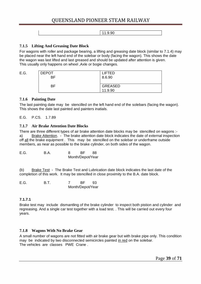
7.1.5 Lifting And Greasing Date Block
For wagons with roller and package bearing, a lifting and greasing date block (similar to 7.1.4) may be placed near the left hand end of the solebar or body (facing the wagon). This shows the date the wagon was last lifted and last greased and should be updated after attention is given. This usually only happens on wheel ,Axle or bogie changes.
E.G. DEPOT BF
LIFTED 8.6.90
BF GREASED 11.9.90
7.1.6 Painting Date
The last painting date may be stencilled on the left hand end of the solebars (facing the wagon). This shows the date last painted and painters inatials. E.G. P.CS. 1.7.89
7.1.7 Air Brake Attention Date Blocks
There are three different types of air brake attention date blocks may be stencilled on wagons :- a) Brake Attention. - The brake attention date block indicates the date of external inspection off all the brake equipment . This may be stencilled on the solebar or underframe outside members, as near as possible to the brake cylinder, on both sides of the wagon. E.G. B.A. 8 BF 88 Month/Depot/Year (b) Brake Test - The Brake Test and Lubrication date block indicates the last date of the completion of this work. It may be stencilled in close proximity to the B.A. date block. E.G. B.T. 7 BF 93 Month/Depot/Year
7.1.7.1
Brake test may include dismantling of the brake cylinder to inspect both pistion and cylinder and regreasing. And a single car test together with a load test. . This will be carried out every four years.
7.1.8 Wagons With No Brake Gear
A small number of wagons are not fitted with air brake gear but with brake pipe only. This condition may be indicated by two disconnected semicircles painted in red on the solebar. The vehicles are classes PWE Crane .

QUEENSLAND PIONEER STEAM RAILWAY
Page 40 of 71
7.1.9 Unit Length
The unit length of wagons may be stencilled near the wagon class and number. .
7.1.10 Drawgear Classification
The drawgear classification of wagons may be stencilled near the wagon class and number. E.G. D.1.
7.2 CARRIAGE MARKINGS
7.2.1 Carriage And Number
The carriage class and number may be stencilled on left hand end above the headstock at each end of the carriage. The carriage number may also painted on the side of the body. The type of carriage can be painted near the entrance of the car and sometimes in the centre of the top panelling.
7.2.2 Carriage Tare Weight
The tare weight may be stencilled on the left hand end of the car, looking towards the coach end from the side.
7.2.3 Lifting And Oiling Date Block
This is the same as for wagons (see Section 7.1.4).

QUEENSLAND PIONEER STEAM RAILWAY
Page 41 of 71
Vehicle lifting for inspecting bolster pivot castings shall be every four years.
7.2.4 Lifting And Greasing Block
This is be the same as for wagons (see Section 7.1.5).
7.2.5 Painting Date
The painting date may be painted on the solebar of the extreme right hand end (facing the side of the car) or on the left hand side of the carriage end.
7.2.6 Air Brake Attention Date Blocks
This will be the same as for wagons (see Section 7.1.7).
7.2.7 Unit Length
The unit length of carriage may be stencilled on the right hand side of the carriage end (just above the headstock).
7.2.8 Drawgear Classification
The drawgear classification of carriage may be stencilled on the right hand side of the carriage end above the stencil of the unit length.
7.2.9 Water Tank Cock
W.T. may be painted over the water tank cock to indicate that they are the water filling cocks.

QUEENSLAND PIONEER STEAM RAILWAY
Page 42 of 71
8. CARRIAGE MISCELLANEOUS EQUIPMENT
8.1 WATER RAISING UNITS
A number of carriages and vans are fitted with water tanks mounted under the frame. These tanks are supplied with air from the train line, and under pressure the water is forced up to the higher levels of the vehicles. The train line pressure of 474 kpa is too high for pressurising the water system so a reducing valve is introduced between the train line and the water tank. Two types of reducing valves are used in the service - (a) the standard gun type valve fitted to the ordinary stock, and (b) an air pressure governor unit fitted to rail motors The former is a self contained unit set to give a pressure of 86 - 103 in the water tank. No adjustment is available and if this unit becomes defective it should be changed. The latter type fitted to the rail motors is a car service unit, incorporating a non return relief valve and air pressure reducing valve. This unit is set for a pressure of 86 - 103 kpa but does not function until 415 kpa is available in the train line. No ready means of adjustment in traffic is available and if this service unit becomes defective it should be changed. At present QPSR have none of these however in the future that may change .
8.2 PASSENGER INTERCOMMUNICATION GEAR
This gear is installed in some carriages. The apparatus comprises a valve contained in a box and which is fitted with an identification disc. In case of emergency, a chain or handle can be pulled from various positions inside the coach. In pulling the chain, the valve is opened, which releases air from the brake pipe and the brakes are applied. To indicate to a railway official that the valve has been operated, the disc, which normally lies in a horizontal position, takes up a vertical position and can therefore be readily observed. The resetting of the valve is carried out by returning the disc to the horizontal position. All wooden carriages fitted with this device have the indicator disc placed at the ends of the coaches just below the roof which may be painted white.

QUEENSLAND PIONEER STEAM RAILWAY
Page 43 of 71
9. GENERAL
9.1 ADJUSTMENT AND OILING OF HAND BRAKES ON CARRIAGES AND VANS
It is the duty of examiners to attend to the adjustment and oiling of handbrakes on carriages and brake vans. Guards are instructed to assist and draw the attention of the examiner to handbrakes not properly adjusted or oiled. Where such attention is necessary, particulars shall be endorsed on the reporting form. IT SHALL BE NOTED NO PINS SLIDES OR ANY PART OF THE BRAKE GEAR ARE TO BE OILED OR GREASED.
9.2 REMOVAL OF CHOCKS FROM WHEELS
Station Masters, Guards, Shunters and others concerned, particularly Train Examiners must see that chocks are removed from the wheels of vehicles before shunting. Any neglect in this direction shall be treated as a serious matter. Sprags are no longer to be used.
9.3 MARKING OFF ROLLINGSTOCK FOR REPAIRS
When it is necessary to mark carriages, brake vans, or vans for repairs, such markings must be made on the footboards or solebars only. The report shall be submitted to the Rolling Stock Supervisor.
9.4 EMERGENCY COUPLING LINKS
These links known as “D” links may be supplied to all Brake vans , to be used when a drawhook is broken. The large pin will pass through the hole provided in the drawbar and the link connected to the screw coupling.
9.5 FAILURE OF DRAWGEAR ON VEHICLES
In the event of the drawgear breaking behind the headstock of a vehicle preventing the use of an emergency coupling with the shackle through the drawbar slot may be used as illustrated below This procedure applies to bogie stock only.
QUEENSLAND PIONEER STEAM RAILWAY
Page 44 of 71
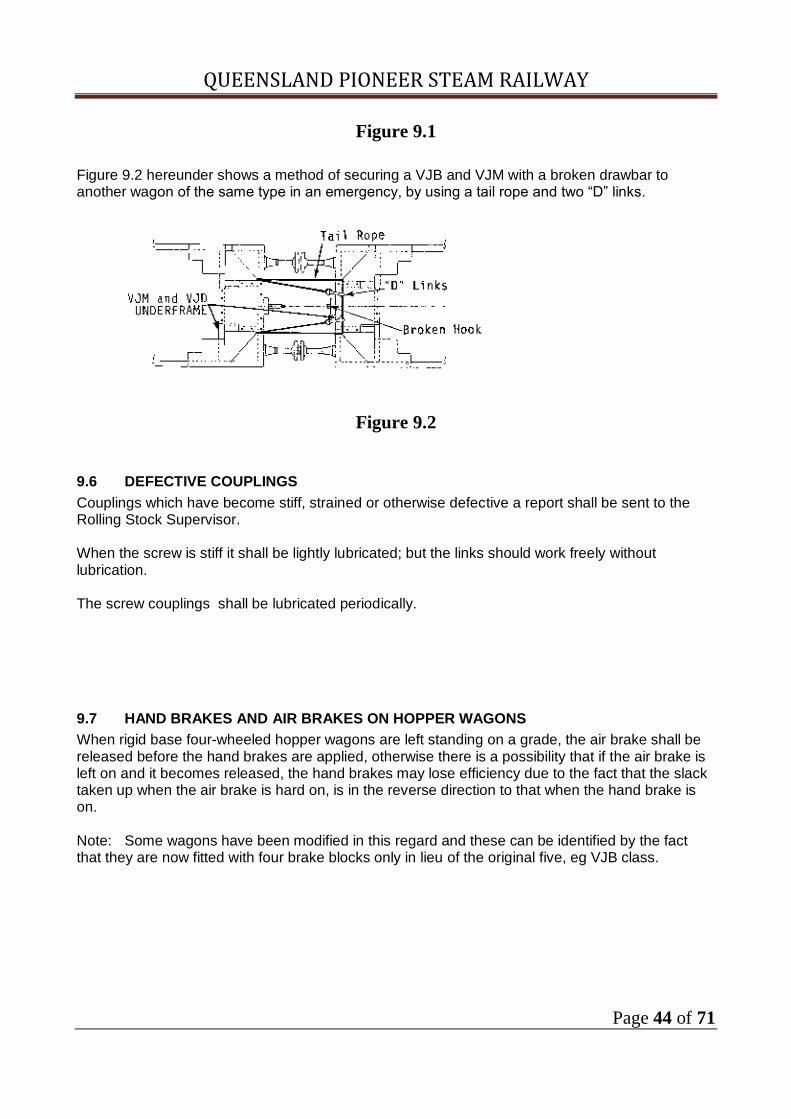
Figure 9.1
Figure 9.2 hereunder shows a method of securing a VJB and VJM with a broken drawbar to another wagon of the same type in an emergency, by using a tail rope and two “D” links.
Figure 9.2
9.6 DEFECTIVE COUPLINGS
Couplings which have become stiff, strained or otherwise defective a report shall be sent to the Rolling Stock Supervisor. When the screw is stiff it shall be lightly lubricated; but the links should work freely without lubrication. The screw couplings shall be lubricated periodically.
9.7 HAND BRAKES AND AIR BRAKES ON HOPPER WAGONS
When rigid base four-wheeled hopper wagons are left standing on a grade, the air brake shall be released before the hand brakes are applied, otherwise there is a possibility that if the air brake is left on and it becomes released, the hand brakes may lose efficiency due to the fact that the slack taken up when the air brake is hard on, is in the reverse direction to that when the hand brake is on. Note: Some wagons have been modified in this regard and these can be identified by the fact that they are now fitted with four brake blocks only in lieu of the original five, eg VJB class.

QUEENSLAND PIONEER STEAM RAILWAY
Page 45 of 71
10. AIR BRAKE SYSTEM- CARRIAGE AND WAGON
10.1 GENERAL DESCRIPTION
The locomotive, carriage and wagon brake system is continuous throughout the train, and is dependant for its operation on the compressed air furnished in the first instance by the air compressor on the hauling locomotive. The air compressor charges up the main reservoir, from which the compressed air is admitted by the driver’s brake valve to the brake pipe (which extends the full length of the train) as shown in figure 10.1.
Figure 10.1
On individual vehicles the air is passed through a triple valve into an auxiliary reservoir as shown in Figure 10.2. The particular triple valve that is fitted is dependant on the size of the brake cylinder or the size of the dummy volume on relayed equipped wagons.
Figure 10.2
The brakes are applied by the regular reduction of air pressure in the brake pipe, produced either purposely or accidentally. The greater auxiliary reservoir pressure then moves the piston, cutting off the communication between the brake pipe and the auxiliary reservoir to flow into the brake cylinder, the piston of which is forced outwards and through a combination of levers that applies

QUEENSLAND PIONEER STEAM RAILWAY
Page 46 of 71
the brake blocks to the wheels as shown in Figure 10.3. The braking force thus produced is proportional to a reduction in the brake pipe pressure. The driver can graduate the braking force as required by means of the brake valve.
Figure 10.3
The brakes are released by increasing the pressure in the brake pipe above the pressure in the auxiliary reservoirs, resulting in the triple valve pistons or diaphragms being forced over into release position, whence the communication between the brake cylinder and the auxiliary reservoir is closed, but the brake cylinder pressure is allowed to escape to the atmosphere as shown in Figure 10.4.
Figure 10.4
In this position, the communication between the brake pipe and the auxiliary reservoir is opened, thus charging the auxiliary reservoir to brake pressure. The brake pipe pressure is increased by admitting compressed air from the main reservoir through the Driver’s brake valve into the brake pipe. The brakes are usually applied by the driver, or in the case of an emergency by the guard. On passenger vehicles, an emergency brake application can be activated by the a passenger, but a brakeaway, rupture of a hose coupling pipe or any other cause resulting in escape of air from the brake pipe, can also bring about an immediate application of the brakes throughout the train.

QUEENSLAND PIONEER STEAM RAILWAY
Page 47 of 71
Figure 10.5
In addition to the automatic brake, all diesel mechanical, diesel electric and diesel hydraulic locomotives are fitted with an independent brake which may be used to apply, or release the locomotive brakes independently, or in conjunction with the train automatic brake.
10.2 CARRIAGE AND WAGON BRAKE EQUIPMENT
All carriages and wagons (except those vehicles mentioned in Section 8.1.8) are fitted with air brake equipment. Figure 10.6 shows a typical schematic arrangement of the basic freight brake equipment on wagons.
Figure 10.6

QUEENSLAND PIONEER STEAM RAILWAY
Page 48 of 71
10.2.1 Functions Of The Triple Valve
Each passenger and goods vehicle is fitted with a TRIPLE VALVE and auxiliary reservoir which are connected to the brake pipe by means of a branch pipe. The brake pipe conducts compressed air throughout the train and the auxiliary reservoir on each vehicle stores it for applying the brakes on that particular vehicle. The triple valve has three connections, one from the brake pipe, one to the auxiliary reservoir and one to the brake cylinder, and it is called a triple valve because it performs three separate functions as follows:- (a) charges the auxiliary reservoir by permitting compressed air to flow from the brake pipe into the auxiliary reservoir where it is stored for applications of the brake, (b) applies the brakes by allowing the compressed air stored in the auxiliary reservoir to flow into the brake cylinder, thus applying force to the brake cylinder piston which causes the brake shoes to be applied to the wheels through the brake rigging, and (c) releases the brake by permitting compressed air from the brake cylinder to escape to the atmosphere. The spring behind the brake cylinder piston returns the piston to the release position. The auxiliary reservoir is recharged during this operation.
Figure 10.7
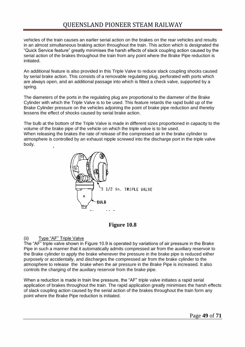
10.2.2 A General Description Of The Four Types Of Triple Valves.
(i) 3 1/2 in Triple Valve The Triple Valve, in Figure 10.7 is operated by variations of air pressure in the Brake Pipe in such a manner that it automatically admits compressed air from the auxiliary reservoir to the brake cylinder to apply whenever the pressure in the Brake Pipe is reduced either purposely or accidentally, and discharges the compressed air from the Brake Cylinder to the atmosphere to release the brake when the air pressure in the brake pipe is increased. It also controls the charging of the auxiliary reservoir from the Brake Pipe. When the Triple Valve is in release position the bulb is in communication with the atmosphere. When a brake application is made the bulb is closed to the atmosphere and opened to the brake pipe thereby causing an additional local brake pipe reduction. When a brake application is initiated by the Automatic Brake Valve this local reduction of brake pipe pressure produced on the leading
QUEENSLAND PIONEER STEAM RAILWAY
Page 49 of 71
vehicles of the train causes an earlier serial action on the brakes on the rear vehicles and results in an almost simultaneous braking action throughout the train. This action which is designated the “Quick Service feature” greatly minimises the harsh effects of slack coupling action caused by the serial action of the brakes throughout the train from any point where the Brake Pipe reduction is initiated. An additional feature is also provided in this Triple Valve to reduce slack coupling shocks caused by serial brake action. This consists of a removable regulating plug, perforated with ports which are always open, and an additional passage into which is fitted a check valve, supported by a spring. The diameters of the ports in the regulating plug are proportional to the diameter of the Brake Cylinder with which the Triple Valve is to be used. This feature retards the rapid build up of the Brake Cylinder pressure on the vehicles adjoining the point of brake pipe reduction and thereby lessens the effect of shocks caused by serial brake action. The bulb at the bottom of the Triple Valve is made in different sizes proportioned in capacity to the volume of the brake pipe of the vehicle on which the triple valve is to be used. When releasing the brakes the rate of release of the compressed air in the brake cylinder to atmosphere is controlled by an exhaust nipple screwed into the discharge port in the triple valve body.
Figure 10.8
(ii) Type “AF” Triple Valve The “AF” triple valve shown in Figure 10.9 is operated by variations of air pressure in the Brake Pipe in such a manner that it automatically admits compressed air from the auxiliary reservoir to the Brake cylinder to apply the brake whenever the pressure in the brake pipe is reduced either purposely or accidentally, and discharges the compressed air from the brake cylinder to the atmosphere to release the brake when the air pressure in the Brake Pipe is increased. It also controls the charging of the auxiliary reservoir from the brake pipe. When a reduction is made in train line pressure, the “AF” triple valve initiates a rapid serial application of brakes throughout the train. The rapid application greatly minimises the harsh effects of slack coupling action caused by the serial action of the brakes throughout the train form any point where the Brake Pipe reduction is initiated.

QUEENSLAND PIONEER STEAM RAILWAY
Page 50 of 71
The “AF” triple valve offers a retarded recharge facility, the purpose of which is to obtain a more even build up of train pipe pressure, both at the front and rear portion of the train.
Figure 10.9
(iii) Type “W” Triple Valve The type “W” triple valve is illustrated externally in Figure 10.10 the metallic parts of the valve being manufactured from aluminium alloy, thereby achieving a saving in weight and reduction of corrosion, but necessitating greater care in handling to prevent damage. The type “W” triple valve will fit onto the existing ‘AF’ or ‘3 1/2” improved’ triple valve brackets without any modifications to the pipe connections. This feature has been include to avoid any conversion problems on existing cars fitted with earlier valves. A type WF2 triple valve is formed by adding the accelerated release and retarded recharge features to the left hand side, and the inshot and reduction ensuring features to the right hand side of the basic valve. The WF3 valve type does not have the accelerated release feature, but in all other respects is similar to the type WF2. The basic triple valve only is used, that is, with none of the additional features; in this form it may replace the improved (Bulb) Triple Valve. In this case, the sides of the valve are fitted with plain covers.

QUEENSLAND PIONEER STEAM RAILWAY
Page 51 of 71
Figure 10.10
The basic “W” triple valve may be fitted with a number of optional features, these being governed by the conditions of service encountered. The following features are utilised. (a) An AIR SHOT AND REDUCTION ENSURING VALVE, which ensures a sufficient brake pipe reduction to allow the brake cylinders to rapidly develop a minimum pressure of 70 kPa by an inshot of air, thus giving a prompt and positive application of the brake shoes to the wheels. In addition this valve maintains the brake cylinders at 70 kPa, from the brake pipe, should brake cylinder leakage reduce its pressure below this value. (b) A RETARDED RECHARGE VALVE that controls the auxiliary reservoir recharging process, so that the available air in the brake pipe, is evenly distributed throughout the entire length of the train, and is not absorbed by the auxiliary reservoirs on the front cars only. This gives improved uniformity of recharging the train’s auxiliary reservoirs. This feature is recommended for use where 32mm brake pipe exceeds 600 metres in length. (c) On long trains, such as in excess of 900metres of 32mm brake pipe, an ACCELERATED RELEASE feature is recommended to assist in giving a series of release impulses by locally increasing the brake pipe pressure in addition to the normal main reservoir source of recharge. This feature ensures an effective release at low speeds and a minimum delay in releasing a brake application, and eliminates dragging brakes. An accelerated release reservoir is required to be connected to the triple valve. The triple valve uses porous plastic filters fitted in the brake pipe and auxiliary reservoir connections to hold back particles larger than 25 micron, thus ensuring that the internal portions of the valve are kept in a clean condition (one micron equals 0.001 millimetre). The sensitivity of the triple valve is such that it is possible, with 31.75mm diameter brake pipe, to obtain service application rates of approximately 300metres per second, and a release rate of approximately 200 metres per second. (iv) Davies and Metcalfe Triple Valves as yet none are in service
10.2.3 Auxiliary Reservoirs
Every air braked vehicle with the exception of Diesel locomotives , is provided with an Auxiliary reservoir in which compressed air, which is supplied from the Main Reservoirs on the locomotive
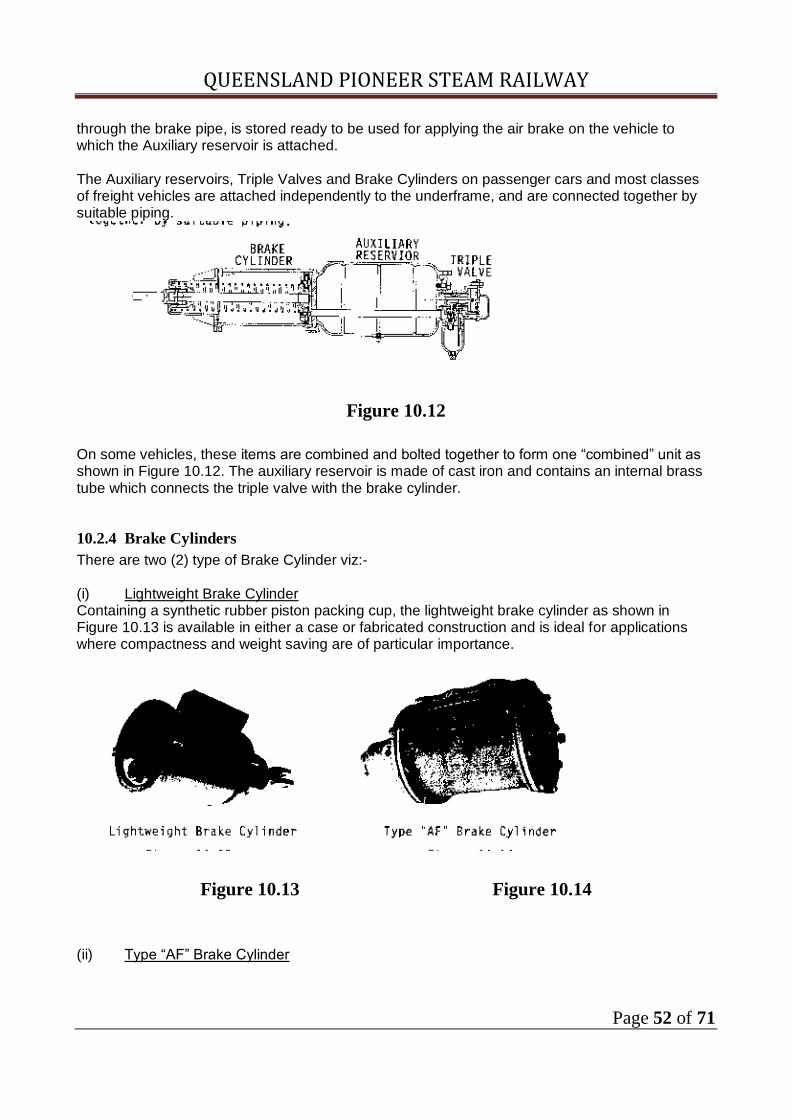
QUEENSLAND PIONEER STEAM RAILWAY
Page 52 of 71
through the brake pipe, is stored ready to be used for applying the air brake on the vehicle to which the Auxiliary reservoir is attached. The Auxiliary reservoirs, Triple Valves and Brake Cylinders on passenger cars and most classes of freight vehicles are attached independently to the underframe, and are connected together by suitable piping.
Figure 10.12
On some vehicles, these items are combined and bolted together to form one “combined” unit as shown in Figure 10.12. The auxiliary reservoir is made of cast iron and contains an internal brass tube which connects the triple valve with the brake cylinder.
10.2.4 Brake Cylinders
There are two (2) type of Brake Cylinder viz:- (i) Lightweight Brake Cylinder Containing a synthetic rubber piston packing cup, the lightweight brake cylinder as shown in Figure 10.13 is available in either a case or fabricated construction and is ideal for applications where compactness and weight saving are of particular importance.
Figure 10.13 Figure 10.14
(ii) Type “AF” Brake Cylinder

QUEENSLAND PIONEER STEAM RAILWAY
Page 53 of 71
Of robust construction, the cast iron, “AF”, long stroke brake cylinder has been designed to give long service with low maintenance even when subjected to the rigorous conditions that exist under freight service. The brake cylinder pistons are manufactured from an iron alloy and are fitted with a leather packing cup. Lubrication of the packing cup is provided for by external greasing connectors which are located in the cylinder body. Application of excess grease should be avoided. To prevent the entry of dirt, push rod wiper rings and a filtered breather are built into the dome head of the brake cylinder. The weight of each vehicle determines the size and the number of brake cylinders which are fitted. For example an ‘FJS’ wagon has one (1) 150mm diameter brake cylinder, whereas, a carriage may have one(1) 300mm diameter brake cylinder .
10.2.5 Brake Rigging
The design of the brake rigging is an important factor affecting the efficient performance of the brakes in service and the most careful attention should always be given to the arrangement of the levers and rods to ensure that the rods exert the most effective pulls on the levers, and that their range and travel are maintained free from any interference or unnecessary friction in any position of the vehicle on the track Figure 10.15 illustrates diagrammatically the principle parts of the brake rigging on a vehicle. The brake cylinder provides the force for the air brake. This force is transmitted through the levers and rods of the brake rigging to each brake block in order to obtain the pressure desired between it and the wheel. The hand brake is applied by rotating the hand brake brake wheel. A chain is wound around a spindle, thus pulling the live cylinder lever A; which is then transmitted through the rigging in a similar manner to the force produced by the air pressure. To maintain the hand brake force, a pawl locks a gear wheel on the handbrake spindle.
Figure 10.15

QUEENSLAND PIONEER STEAM RAILWAY
Page 54 of 71
10.2.6 Hand Release Valve
A hand release valve is fitted to all wagons provided with air brake equipment. It may be used for releasing the compressed air from the auxiliary reservoir thereby moving the triple valve and releasing the air from the brake cylinder and releasing the brakes on a particular vehicle. The release valve is generally fitted either direct to the Auxiliary Reservoir or its related air pipe. The release valve, when operated, should be kept open only until the triple valve commences to discharge the air from the Brake Cylinders. The release valve should then be closed unless it is desired to completely drain the compressed air from the equipment, when the valve must be held open until the flow of air ceases. Note that on any occasion as soon as the handle is set free an internal spring returns the valve to its seat and prevent the escape of air to atmosphere.
Figure 10.16
10.2.7 Triple Valve Isolating Cock
A triple valve isolating cock is fitted to the branch pipe between the Brake Pipe and the Triple Valve; it is a plug type cock of similar construction to a brake pipe cock. These isolation cocks are for the purpose of isolating the automatic brake equipment of the vehicle when it is either defective or repairs are being effected when the Brake Pipe is charged with compressed air.

QUEENSLAND PIONEER STEAM RAILWAY
Page 55 of 71
10.2.8 Type “J” Automatic Slack Adjuster
Figure 10.17
Uneven brake cylinder piston travel produces damaging an undesirable braking effects. The type “J” cast iron slack adjuster automatically maintains the brake cylinder piston travel at a constant predetermined amount and therefore ensures even and flexible braking irrespective of brake block wear. Mounting of the slack adjuster may be either separately or by fixing directly to the brake cylinder pressure head. The slack adjuster is automatic only in taking up slack in the brake rigging. The slack must always be let out, when necessary, by turning the adjuster nut by hand.
10.2.9 Brake Pipe Coupling Cocks
All brake pipe coupling cock handle should be positioned so that movement of the cock handle due to vibration opens the cock. In general (a) 32mm(1 1/4”) bent handle cocks have the handle pointing upwards when closed and in line with the hose coupling when open.
Figure 10.18

QUEENSLAND PIONEER STEAM RAILWAY
Page 56 of 71
(b) 25mm (1”) straight handle clock have the the handle in the horizontal position when closed and vertically down when open.
Figure 10.19
All vented cocks must be arranged so that the hose pipe is vented when cock closed. If a brake pipe coupling cock is found incorrectly fitted, the wagon is to be marked off for repairs.
10.2.10 Brake Pipe and Hose Coupling Pipes.
Figure 10.18
The Brake Pipe extends from the Automatic Brake Valve to both ends of the locomotive and to the rear vehicle on the train, communication being made between the locomotive and other vehicles by means of flexible Hose Pipes which are mounted with metallic fittings to enable one end of the hose pipe to be attached to the Brake Pipe Cock and the other to be readily coupled and uncoupled to its fellow on the adjoining vehicle as required. The hose coupling heads are alike as illustrated in Figure 10.18 which shows the relative position in which they must be placed before they can be united. After being placed in this position the coupling heads are revolved until the projecting lugs fit securely into their corresponding grooves. Each coupling head is provided with a rubber packing ring, so arranged that when the coupling heads are united, these rings face each other and are forced securely together by Brake Pipe pressure thereby ensuring an air tight joint and producing a locking action which prevents the hose pipes being irregularly uncoupled by train slack action.

QUEENSLAND PIONEER STEAM RAILWAY
Page 57 of 71
10.2.11 Centrifugal Dirt Collectors.
Figure 10.19
Centrifugal Dirt Collectors are located on triple valve branch pipes and on other air pipes where considered necessary. They are provided to protect the Air Brake fittings against the entrance of pipe scale, dirt, water or foreign substances of any kind. Figure 10.19 is a sectioned view of the standard type with the detachable dirt chamber. The design comprises two separate portions, the upper or body portion to which the pipe connections are made and the lower or dirt chamber portion. The two portions are bolted together and the joint made with an air tight gasket. Centrifugal dirt collectors for use on the air pipes of locomotives, where the presence of water in the piping is more prevalent, are provided with a small drain cock on the bottom of the dirt chamber which enables it to be drained at frequent intervals. Centrifugal action causes dirt or foreign particles to fall to the bottom of dirt chamber. Loose pressed brass cone 5 prevents flow of dirt from chamber into brake pipe as the cone lifts with flow of air and seals off the dirt chamber.
10.3 PERMISSIBLE PISTON TRAVELS
As brake blocks wear, the clearance between the brake block and the wheel increase, therefore to apply the brake, the brake piston has to move out further. To keep the brake piston travel within safe limits, adjustments is provide on pull rods. If this adjustment is neglected , the brake piston travel will ultimately increase to a point when the brake cylinder cover is fouled, thus rendering the brake useless. Brake cylinder piston travel limit on all vehicles.
Min. mm
Max. mm
Passenger cars without slack adjusters or with slack adjusters and with 254mm(10 inch) brake cylinders (long stroke cylinder) also brake vans
100 180
Cars fitted with 305mm (12 inch) brake cylinders (long stroke cylinder)
140 165
Wagons with long stroke brake cylinders 100 180
Wagons with short stroke brake cylinders (Hopper class only, VJMG, VTJ, )
50 100

QUEENSLAND PIONEER STEAM RAILWAY
Page 58 of 71
10.4 ADJUSTMENT OF BRAKES
Brake rigging comprises of all brake levers and links, hinges and pull rods, brake hoses and brake blocks which enable the brake cylinder to transmit its force to the wheel. Before attempting to adjust the brake rigging on any car, van or wagon or to disconnect for any purpose, or other employee must see that the air brake and hand brakes, where provided, are fully released, that the triple valve isolating cock is closed and that all compressed air is exhausted from the auxiliary reservoir. On completion of the adjustments, the triple valve isolating cock or branch pipe cock must be opened. Even with these essential precautions, under no circumstances shall the finger be used to align holes during the adjustment. A condemning groove/mark is contained in brake blocks and where brake blocks are worn to this groove or 12mm thickness, new blocks must be fitted. It is important to note that when replacing worn blocks, every effort should be made to pair all part worn blocks. See list for various types of brake blocks and guide to class of vehicles fitted. Ref. Table 10.1. Different means of adjusting the brakes are provided on various types of vehicles. Some adjustments are made by pin connections, others by screw and nuts. On hopper wagons the adjustment is by means of brake adjusting rods outside the wheels through staggered holes at on end. It is necessary with these wagons to have the adjustment made so that the adjusting pin is always in the bottom row of holes. If the necessary adjustment cannot be obtained, it is required that the rod be turned over. This is done so as to provide more clearance between the rod and the rail. Where the brake blocks are on the outside of the wheel, the taking up of wear is done by shortening the adjusting rod by bringing the blocks closer to the wheels. Where the blocks hang inside the wheels, as in the case of diamond frame bogies, one type of plate frame bogie and ride control bogie, the adjustment is made by lengthening the adjustment or push rod and pushing the blocks closer to the wheels. Care should be taken when adjusting the brakes on fixed wheel stock and those bogies having horn check guides, to ensure against over adjustment when the wagon is in a loaded condition. If adjusted too tight, there is a possibility of brakes dragging or locking when the wagon is in the unloaded condition. If the adjustment is made to give the minimum permissible travel in a loaded condition, this should satisfactorily meet the position when the wagon is in the loaded condition

QUEENSLAND PIONEER STEAM RAILWAY
Page 59 of 71
TYPES OF BRAKE BLOCK TABLE 10.1
the following is a list of Brake blocks available from Queensland Rail or Contractors
Pattern No. Stock Item No. Material Used On
WZC 3 48200103 Cast Iron (C1) Carriages and Wagons with 660mm (26 inch) diameter wheels.
WZC 4 4820177 C1 Carriages and Wagons with 850mm, 915mm (33.5, 36 inch diam wheels
CKC 9 48200311 C1 Wagons with 850mm (33 1/2 inch) diam. wheels
CKC 29 48200335 C1 Cutting block (as per CKC 9 use)
W3C 37 48201212 C1 Carriages and Wagons with 660mm(26 inch) diam. wheels to cast steel bogies
DMC 20 48200672 C1 D.H. Locos
1T2.2 48203492 Non Metallic (WM) Fast freight, mineral wagons and wagons with brake shoes machined for non metallic brake blocks.
PIRB 48203985 WM All DE and DH Locomotives
Locomotive Brake Blocks
LCC24 PB15 Driver CI
LZC28 Tender Block ALL
CI
LHC24 C17 Driver CI
10.5 METHOD OF ADJUSTING HANDBRAKES ON WAGONS
The examiners must adjust the brake pull rod on the hand brake end of the wagon so that the hand brake lever will fall on its own to no lower than the third pinhole on the rack, when the brake blocks are brought against the wheels. Then the pull or push rods on the other bogies must be adjusted to give the correct brake piston travel.
QUEENSLAND PIONEER STEAM RAILWAY
Page 60 of 71
Some wagons are provided with an independent hand brake adjustments on the hand brake pull rod, and this must be worked in conjunction with the ordinary brake adjustment. When adjusting the brake on fixed wheel stock, it is necessary that the handbrake be released, the hand brake could force the wheel over and would give a false adjustment. Hand brakes on some fixed wheel stock are independent of the air brake, having a single block attached to the brake lever.

QUEENSLAND PIONEER STEAM RAILWAY
Page 61 of 71
10.6 Passenger Cars and Brake Vans
Modern type brake vans, class TGVS and some QLX which are fitted with the Westinghouse diaphragm triple valves types WF3 , WF2 or WP and AF brake cylinders may receive air brake overhaul every four(4) years. This may include the dismantling of the brake cylinder.
This instruction applies only to stock in regular use eg ; Passenger cars Maintainence stock Locomotives and Rail cars All other stock shall be inspected before use (display stock) or seldom used vehicles. The inspections shall only apply to the period of use only. This is done on the reporting form .
10. 7 Wagons and Carriages
The air brake equipment on all wagons shall be inspected provided that the periods tabulated below for various types of brake equipment are complied with :-
Triple Valve Type Brake Cylinder BA Date
BT Date
Westinghouse Type 89mm I.T.V and AF.2
Old style without external lube points 1Year 4Year
Westinghouse Type ‘W’
Davies and Metcalfe without external lube points
1Year 4Year
Westinghouse Type 89mm I.T.V. and AF. 2
Westinghouse Type AF 1Year 4Year
Westinghouse type ‘W’
Westinghouse Type AF and Type WF 1Year 4Year
BA: Brake Attention Date indicates the date of external inspection of all items of brake equipment
BT: Test Date indicates the test of wagon air equipment and components .
This may be done by doing a single car test. Also load test brakes on each bogie if bogie vehicle.
This is also done after overhaul or major maintainece

QUEENSLAND PIONEER STEAM RAILWAY
Page 62 of 71
10.7.1 Inspections both Wagons and Carriages
All wagons and carriages shall when inspected both prior to operation and annual inspections the following shall be checked:
as per Form 1

QUEENSLAND PIONEER STEAM RAILWAY
Page 63 of 71
10.8 TRAIN REQUIREMENTS FOR VEHICLES HAVING BRAKES CUT OUT
Unless in the case of an emergency which includes travel to the next station only no passenger vehicle shall operate with the Air Brake cut out.
10.9 PROCEDURE FOR CUTTING-OUT BRAKES
(i) On any vehicle on which the air brake is found to be defective and which cannot be repaired in the available time, the air brake may be cut out by triple valve isolating cock (branch pipe cock); (ii) When the brakes on the vehicle are cut out, the auxiliary reservoir shall be bled down to
atmospheric pressure by means of the release valve on the auxiliary reservoir or its related piping.
(iii) In all cases the examiner shall fillout a report. (iv) The air brake shall not be cut out on any vehicle unless it is defective;
10.10 ISSUE OF SPECIAL AUTHORITY.
The requirements of vehicles with air brake cut out apply to general traffic conditions which includes Passenger and Maintainance Trains. To meet specific requirements the Examiner will in accordance with clause 10.9 (I) (ii) (iii) issue form 1 which will list the conditions under which a vehicle can be moved either in train or otherwise also listing times and speed restrictions.
10.10.01 Movement of seldom used or vehicles under repair in Depot area
The Rolling Stock Supervisor will inspect the vehicle/s .
(1) Check bearings and oil if necessary , Roller Bearings visual check (2) Check for equipment dragging (3) Test air brake if operational if not operational vehicle will only be moved at walking pace. (4) Check coupling points Buffers/ drawhook or auto for operation and security. (5) With vehicles with damaged drawgear extra care shall be taken to avoid separation. (6) This shall be noted on a form1

QUEENSLAND PIONEER STEAM RAILWAY
Page 64 of 71
11. BRAKE EQUIPMENT DEFECTS AND TROUBLE SHOOTING
During the testing of carriages and wagon air brake equipment, certain defects may reveal themselves and it is the duty of the train examiner to correct these defects where possible. Certain defects will show up, and to permanently correct these would be beyond his capacity as a train examiner. Set out hereunder are defects which may occur and also shown is possible cause and corrective action to be taken by Examiner in each instance:-
FAULT CAUSE REMEDY
1. Brakes will not apply Branch pipe closed Open Cock
Defective Triple Valve Mark for Attention
Leakage from Aux. Reservoir or related piping
Tighten up joints
2. Excessive Brake pipe leakage
Defective Joints Check all piping and joints and hose-pipes. Tighten defective joints.
Defective Triple Valve Mark for Attention
3. Brakes will not release
Exhaust nipple blocked Remove exhaust nipple and clean port
4. Brakes leak off in less than 1 minute after application
a. Brake piston travel too short
Adjust piston to correct setting for the particular class of vehicle
b. Leakage from Auxiliary reservoir or its related piping.
Tighten up joints
c. Leakage from release valve
Renew leather packing washer
d. Brake cylinder leather defective. Leakage can be detected by placing hand over brake push rod or sleeve
Mark vehicle off for attention
e. Pressure head gasket leaking (Joint between auxiliary reservoir and cylinder
Tighten up joint
5. No local reduction discernible by absence of blow at bulb exhaust port when brakes are released
Siphon tube made up (89mm improved T.V. only).
Mark for attention
6. Blow at exhaust nipple when brakes released - no blow at bulb exhaust port.
Reservoir end gasket defective
Mark for attention
7. Blow at exhaust nipple and/or at bulb exhaust port with brakes released
Leaky slide valve in triple valve
Make several applications and releases of the brake. If this fails to correct; mark

QUEENSLAND PIONEER STEAM RAILWAY
Page 65 of 71
off for brake attention.
8. Blow at exhaust nipple with brakes released
Perforated brass tube combined set
Mark for attention
9. Blow at exhaust nipple and/or bulb exhaust port with brakes applied
Leaky slide valve Mark for attention
10. Brake cylinder piston moves in and out when brakes re applied
a. Pressure head basket defective b. Piston packing leather defective
Tighten up joint. Mark off for attention.
11. Brakes apply and release irregularly when they should be released
a. Loose triple valve cover. Variation in supply pressure
Tighten up bolts evenly.
12. Brakes apply violently Regulating plug worked out
Mark for attention
13. Auxiliary reservoir charges very slowly (AF2 TV only)
Retarded recharge piston spring broken
Mark for attention
14. Brakes apply very slowly (AF2 TV only)
Inshot piston or spring broken
Mark for attention
15. Brakes will apply only lightly (AF2 TV only)
Regulating choke plug made up
Mark for attention
16. No local reduction or quick service activity evident by absence of blow at bulb exhaust port when brakes are released (AF2 TV only)
a. Brake pipe check valve or valve stem are stuck b. Quick service choke plug to chamber II made up
Mark for attention
17. Flowmeter hands will not come together
Brake pipe leaks Close brake pipe behind locomotive and test locomotive. Check train for any audible leaks to repair if possible. If no obvious leaks are found commence from the locomotive, isolate groups of wagons out at a time and retest these wagons.
FORGETFULNESS MAY BE FATAL

QUEENSLAND PIONEER STEAM RAILWAY
Page 66 of 71
12.1 CHECK ALL READILY OBSERVABLE BOLTS AND NUTS ON THE GENERATOR AND OTHER COMPONENTS FOR TIGHTNESS
Special attention should be given to the generator and the suspension pins to see that all cotter pins are in place and in good order.
12.2 HOW TO CHECK THE FREEDOM OF MOVEMENT OF THE GENERATOR ON THE SUSPENSION PIN, INCLUDING LUBRICATION OF THE SUSPENSION PIN AND ADJUSTING SCREWS
To check the freedom of movement of the generator or the suspension pin it is necessary to remove the belt and allow the generator to 'swing' . If any stiffness is observed, an application of a light engine oil with a small proportion of kerosene added, should be applied to the pins where they pass through the generator hangers, and also into a hole In the carcass which leads down to the generator pin. On later type generators a grease cup is provided and is situated between generator suspension lugs. This cup should be kept full and cap tight. Tension screws should be cleaned with a stiff brush and a light dressing of oil should be applied occasionally.
12.3 HOW TO CHECK THE WIRING FOR ABRASION AND THE METHOD OF MAKING TEMPORARY REPAIRS
To find abrasion to carriage wiring, it is necessary to have the carriage placed over a pit or on a ramp for each wire to be checked where it passes over or under the frame. Such abrasions, if any should be bound with insulating tape. If tape is not available, pieces of thin wood, lino or generator belting should be placed between the braided wire and the frame.
12.4 HOW TO CHECK THE BATTERIES FOR LEAKAGE OF ACID
The leakage of acid from the cells in the battery box can be determined usually by the appearance of the battery box. If the bottom of the box is found to be in a saturated state, it could be assumed that the cause is one of the following:- A cell box has been cracked, too much water has been added, or the carriage has been roughly shunted, thus causing the acid to slash from under the lids of the cells. The door of the box should be removed and if a broken cell is found, the carriage should be marked for Electric Light Attention.

QUEENSLAND PIONEER STEAM RAILWAY
Page 67 of 71
12.5 HOW TO REPLACE A FUSE, AND THE CORRECT SIZES AND TYPES TO BE USED IN THE BATTERY AND LIGHTING CIRCUITS RESPECTIVELY.
The main or battery fuse is housed in a cast iron box which is usually screwed to the floor as near as possible to the end of the battery box nearest the generator. Two terminals will be found in this fuse box and across these, the fuse, one strand of eighteen gauge copper wire, is fitted. Interior lighting fuses are located at the main switch. In the external type, the cover must be removed and the terminals carrying the fuses will be found in the bottom left hand corner. Two fuses are necessary as carriages are wired for half and full lights. Interior switches have their fuses plainly visible and are situated at the top of the panel, one on each corner or in adjacent separate fuse units. Capacity of fuse is 15 amps, or one strand of 25 SWG copper wire. An alternative of 1 strand of 10 amp, and one strand of 5 amp, fuse wire in parallel would be satisfactory. If after the fuses have been replaced and the switch is placed in 'on' position, and the fuses again blow, the carriage should be marked for Electric Light Attention: Under no circumstances should heavier fuse wire be fitted, if repeated fusing takes place. In vans, a separate switch board with fuses attached is found in close proximity to the main switch These fuses control such lights as side lamps, van O.G. lights etc. Fine wire such as is used in domestic of 5 amp capacity can be used here.
12.6 REPLACEMENT OF FLUORESCENT TUBES IN VANS
Van must be stationary and main switch "off". Removal (i) Remove both end cap. Use 1 1/4" B.S.W. socket wrench to undo the cap screws (one each end). (ii) Turn tube through 90o so that the pins are vertical retain grip on tube at all times and gently ease tube downwards out of lampholders. Replacement : (i) With pins vertical, slide tube into lampholders and turn into lampholders and turn 90o. Lightly pull tube to ensure it is securely located. (ii) Replace end caps and cap screw
QUEENSLAND PIONEER STEAM RAILWAY
Page 68 of 71
13 IMPORTANT DIMENSIONS FOR CARRIAGE AND WAGONS COMPONENTS
It is of note that these figures are nominal .
13.1 WHEELS
Depth of new wheel flange: 28mm Distance between inside wheel faces - 990mm nominal
13.2 BUFFERS
Nominal distance from headstock: 520mm Sec 5.6.3 Nominal buffer centre height above rail : 812mm
13.3 DRAWGEAR
Distance of drawhook shoulder to headstock: 57mm Nominal Maximum Longitudinal slack of coupler and Draft Gear: 20mm
13.4 STANDARD LOADING DIAGRAM
Overall load width from 916mm to 325Omm, Above Rail : 285Omm Overall load height sides from rails at 285Omm, Overall Width: 3250mm Overall load height centre of wagon: 8OOmm, Overall width: 3820 NOTES 1. Loading the dimensions of which exceed the limits of the full outline shown in figure 13.1, is termed "Out of Gauge" . 2. Allowance must be made for the floor heights of rollingstock which vary and can be up to lO67mm above rail level . 3. Dotted lines represent additional dimensions applicable only to drop centre or low load wagons.
13.5 RAIL CLEARANCE
Minimum clearance from rail to lowest part of vehicle - 64mm.

QUEENSLAND PIONEER STEAM RAILWAY
Page 69 of 71
Figure13.1
QPSR

QUEENSLAND PIONEER STEAM RAILWAY
Page 70 of 71
Appendices
All inspections shall use form QPSR Form 1

QUEENSLAND PIONEER STEAM RAILWAY
Page 71 of 71