role of sulfur oxides iin wear and deposit · pdf filefort belvoir va 22060-5606 program...
TRANSCRIPT

ROLE OF SULFUR OXIDES- iIN WEAR AND DEPOSIT
FORVATIQAIIN ARMY DIESEL*- ENGINES0 INTERIM REPORT DTIC* ~~BFLRF No. 248eE C T rM ._ - -"MAR 2 2 198q
I D.W. Naegeli
H.W. Marbach, Jr.lvoir Fuels and Lubricants Research Facility (Si RI)
Southwest Research InstituteSan Antonio, Texas
Under Contract to
U.S. Army Belvoir Research, Developmentand Engineering. Center
Materials, Fuels and Lubricants LaboratoryFort Belvoir, Virginia
Contract No. DAA,-7-C.0OO43
Approved fol'-publH6 release; distribution unlimited
-- December 1988
." 89' :

UnclassifiedSECURITY CLASSIFICATION OF THIS PAGE
REPORT DOCUMENTATION PAGEIa. REPORT SECURITY CLASSIFICATION lb. RESTRICTIVE MARKINGS
Unclassified None2a. SECURITY CLASSIFICATION AUTHORITY 3. DISTRIBUTION/AVAILABIUTY OF REPORT
N/A Approved for public release;2b. DECLASSIFICATION/DOWNGRADING SCHEDULE distribution unlimited
N/A4. PERFORMING ORGANIZATION REPORT NUMBER(S) 5. MONITORING ORGANIZATION REPORT NUMBER(SI
Interim Report BFLRF No. 248
6a. NAME OF PERFORMING ORGANIZATION 6b. OFFICE SYMBOL 7a. NAME OF MONITORING ORGANIZATIONBelvoir Fuels and Lubricants (if applicable)Research Facility (SwRI)
6c. ADDRESS (City, State, and ZIP Code) 7b. ADDRESS (City, State, and ZIP CodeSouthwest Research Institute6220 Culebra RoadSan Antonio, Texas 78284
8a. NAME OF FUNDING/SPONSORING 8b. OFFICE SYMBOL 9. PROCUREMENT INSTRUMENT IDENTIFICATION NUMBERResearch, Development and
Engineering Center STRBE-VF DAAK70-87-C-00438c. ADDRESS (City, State. and ZIP Code) 10. SOURCE OF FUNDING NUMBERS
PROGRAM PROJECT TASK WORK UNITFort Belvoir VA 22060-5606 ELEMENTNO. NO. IT1611 NO. ACCESSION NO.
61102 02AH5115 FF(3)11. TITLE (Include Security C4la s dton)
Role of Sulfur Oxides in Wear and Deposit Formation in Army Diesel Engines (U)
12. PERSONAL AUTHOR(S)
Naegeli, David W.; Marbach, Jr., Howard W.13a. TYPE OF REPORT 13b. TIME COVERED 114. DATE OF REPORT (Year, Month, Day) 15. PAGE COUNT
Interim FROM Oct 85 TO Sept 87 11988 December 6216. SUPPLEMENTARY NOTATION
17. COSATI CODES 18. SUBJECT TERMS (Continue on revese if neceary and den, by ock numberFIELD GROUP SUB-GROUP . Wear Combustion Deposits
Sulfur Oxides Diesel EnginesDiesel Fuels
19. ABSTRACT (Continue on rever i necessary and identy by block number)
In some locations outside the continental United States, U.S. military ground mobility equipment usesfuel with an increased sulfur content. Fuel sulfur has been identified as a primary contributor todiesel engine wear and deposits. The literature on the effects of fuel-bound sulfur on diesel enginewear indicates that sulfuric acid mist formed within the combustion chamber is responsible forcorrosive attack of the cylinder bore and piston ring areas. Deposit formation has been more of amystery in that the literature tends to support the theory that reaction of organically bound sulfurwith the fuel and lubricant is the principal cause. Studies presented here suggest that sulfur dioxide(S02') formed in the combustion of fuel-bound sulfur is the primary cause of higher cylinder bore/ringwear and deposit formation in diesel engines.
(Cont'd)
20. DISTRIBUTION/AVAILABILITY OF ABSTRACT 21. ABSTRACT SECURITY CLASSIFICATION9 UNCLASSIFIEDIUNLIMITED 11 SAME AS RPT. C DTIC USERS Unclassified
22a. NAME OF RESPONSIBLE INDIVIDUAL 22b TELEPHONE (Inc*de At Code) Mc. OFFICE SYMBOL
Mr. F.W. Schaekel (703) 664-3576 STRBE-VFDD FORM 1473. 84 MAR 83 APR edition may be used unto exhausted. SECURITY CLASSIFICATION OF THIS PAGE
All ottw edito are obsoWt,, Unclassified
UnclassifiedSECURITY CLASSIFICATION OF THIS PA(GE
19. ASBSTRACT (Cont'd)
Several bench-scale experiments were conducted to determine the effects of S02 on corrosion anddeposit formation. It was found that iron sulfide is readily formed by an oxidation-reductionreaction between SO2 and iron when moisture is present. Oil samples containing dissolved waterand SO2 were examined in a wear rig, and the results showed that concentrations of S0 2 as low as0.05 percent caused significant increases in the size of the wear scar. Experiments wereperformed to determine the extent of reaction of 502 with hydrocarbons. Olefins were found to bevery reactive with S02 and formed black insoluble tar-like products. Saturated aliphatics andaromatics were relatively unreactive with SO 2. Thermal stability bench tests showed that smallamounts of S02 dissolved in both fuels and lubricants caused significant increases in depositformation.
Engine tests were performed to determine the relative importance of S02 and sulfuric acid mist.Analysis of the exhaust gases sampled very near the exhaust port showed that at least 99 percentof the exhaust sulfur was SO2 . Sulfuric acid mist did not appear to be present in a significantamount; based on the accuracy of the measureme'its, its concentration could not have exceeded 0.5percent.
Two engine tests were completed to further study the role of SO2 . In the first, SO2 gas wasinjected into the intake manifold of a single-cylinder diesel engine at a concentration equivalent tothat experienced when operating the engine on a fuel containing 2-percent sulfur. These resultsshowed that SO2 was responsible for the formation of deposits in the engine, but was onlyaccountable for about 50 percent of the wear observed in similar tests using fuel-bound sulfur.This difference in wear is not understood, but it may result from the difference between ahomogeneous and a stratified SO2 concentration in the combustion chamber. The second test wasperformed in a three-cylinder diesel engine equipped with individual fuel injection systems for eachcylinder. In this test, high-sulfur (3-percent) fuel was used in two cylinders, and neat fuel was usedin the third cylinder. The results of this test showed that even though the three cylinders sharedthe same lubricant, the cylinders burning the high-sulfur fuel experienced considerably more wearand deposit formation than the cylinder operated on neat fuel. A kinetics modeling study isrecommended to verify and quantify the role of SO2 .
The results of this investigation support a new theory that 502 is the principal cause of fuel sulfurinduced wear and deposit formation in diesel engines. This information will aid lubricantresearchers in formulating improved oils for use with high-sulfur fuel.
', 39'n/or
- A 3. 1
UnclassifiedSECURITY CLASSIFICATION OF THIS PAGE

EXECUTIVE SUMMARY
Problems and Objectives: On certain bases outside the continental United States, fuelsused in U.S. military ground mobility equipment may contain relatively high levels ofsulfur. Fuel sulfur has been identified as a major contributor to diesel engine wear anddeposit buildup. The engine literature indicates relatively broad acceptance of thetheory that sulfuric acid mist formed in the cylinder during the combustion process is theprimary cause of wear. Contrarily, the kinetics and thermodynamics of sulfuric acidformation indicate that sulfuric acid is unlikely to form in the cylinder at the hightemperatures of combustion. Deposit formation is more of a mv"tprv in th;t theliterature suggests that reactions ot fuel sulfur with the lubricant is the principal cause.The objective of the present study is to determine which sulfur-containing species arethe primary causes of engine wear and deposit formation.
Importance of Project: There is clearly a need for a more basic understanding of therole of fuel sulfur in engine wear and deposit formation. Without a more in-depthunderstanding of the mechanisms of sulfur-induced wear and deposit formation in dieselengines, the potential to satisfy future needs by developing additives, more thermallystable lubricants, and improved metallurgy and engine design will be severely limited.
Technical Approach: Several bench-scale type experiments and full-scale engine testswere performed to determine the importance of sulfur dioxide in engine wear and depositformation. Since previous work stressed the importance of sulfuric acid in engine wear,the approach taken in the present study was to perform experiments that tested thesulfuric acid theory against the possibility that sulfur dioxide, in fact, was responsiblefor most of the wear and also deposit formation.
Accomplishments: The results of this study support a new theory that sulfur dioxideformed directly in the combustion of fuel sulfur is responsible for the corrosive wear anddeposit formation in diesel engines. It was found that the mechanism of corrosion bysulfurous acid, H2SO3 , involves an oxidation-reduction mechanism; whereas sulfuric acid,H2SO4, simply behaves as an acid, causing galvanic corrosion. This difference in thecorrosion mechanism may suggest new approaches for inhibiting the corrosion process,e.g., new possibilities may emerge in additive formulations and metallurgy that wouldnot have been considered if sulfuric acid continued to be viewed as the major cause ofcorrosion. Considerable evidence is presented to show that dissolved sulfur dioxide inthe lubricant is the major cause of increased deposits due to fuel sulfur. The fact thatSO2 appears to be the major cause of sulfur-related deposits seems to simplify theproblem and should provide some new direction in solving the problem of deposits indiesel engines.
Military Impact: The benefit of this study is that it will provide direction for futureresearch and development of lubrication additives, corrosion-resistant metallurgy, andimproved engine design. Because sulfur dioxide causes corrosion by a differentmechanism than sulfuric acid and also seems to be largely responsible for deposits, newapproaches to the fuel sulfur problem may emerge that will eventually increase fuelavailability in crisis situations and extend the life of vehicles in the field.

FOREWORD/ACKNOWLEDGMENTS
This work was performed at the Belvoir Fuels and Lubricants Research Facility (SwRI)
located at Southwest Research Institute, San Antonio, TX, under Contract Nos.
DAAK70-85-C-0007 and DAAK70-87-C-0043, for the period I October 1985 through 30
September 1987. Work was funded by the U.S. Army Belvoir Research, Development and
Engineering Center, Ft. Belvoir, VA, vith Mr. F.W. Schaekel (STRBE-VF) serving as
contracting officer's representative. Project technical monitor was Mr. M.E. LePera,
STRBE-VF.
The authors acknowledge the support of the Belvoir Fuels and Lubricants Research
Facility (BFLRF) at Southwest Research Institute (SwRI) engine and chemistry personnel.
The participation of K.B. Jones, K.H. Childress, and R.D. Atiyeh in carrying out the
experimental work in this program is gratefully acknowledged. The authors acknowledge
E.A. Frame for his role in discussing work plans and providing background information.
The work of J.W. Pryor and his editorial staff in preparing this document is greatly
appreciated.
iv

TABLE OF CONTENTS
Section Page
I. INTRODUCTION AND BACKGROUND .............................. I
II. OBJECTIVE ..................................................... . 6
l11. APPROACH ..................................................... . 6
IV. RESULTS .......................................................
A. Engine Tests ............................................... 7B. Sulfuric Acid Measurements .................................. 8C. Effects of Sulfur Dioxide ..................................... 15D. The DD 3-53 Engine Test .................................... 22E. Corrosion Chemistry ........................................ 33F. Wear Tests ................................................. 38G. Effects of Sulfur Dioxide on Lubricants ........................ 43H. Solubility .................................................. 44I. Reactivity ................................................. 461. Thermal Stability ........................................... 48
V. SUMMARY AND CONCLUSIONS ................................... 50
VI. RECOMMENDATIONS ............................................ 53
VII. LIST OF REFERENCES ........................................... 54
APPENDIX
Wheeled-Vehicle Test Procedure for the DD 3-53 Engine ..................... 57
Uv

LIST OF ILLUSTRATIONS
Figure Page
1 Effect of Temperature and Fuel/Air Ratio on the SO3/50 2M ole Ratio ................................................... 3
2 Apparatus for Trapping Out Sulfur Oxides From Diesel Exhaust ......... 93 The Syringe and 0.45-Micron Uniflo Filter Device Used to Retrieve
Dissolved Diesel Exhaust Samples From Trap A in Fig. 2 ............ 114 Iron Buildup in the Lubricant and the Consumption of Lubricant
During the Petter Engine Wear Tests ............................. 195 Effect of Fuel Sulfur on Cylinder Bore Wear ......................... 206 Iron Buildup in the Lubricant and the Consumption of Lubricant
During the DD 3-53 Engine Test ................................. 277 Condition of Cylinders in the DD 3-53 Engine ........................ 298 Condition of the Rings in the DD 3-53 Engine ........................ 309 Condition of the Pistons in the DD 3-53 Engine ....................... 31
10 Comparison of a Virgin Steel Ball Bearing With One That HasBeen Immersed in a 0.1-Percent Aqueous Solution ofSulfuric Acid .................................................. 35
11 Electron Micrographs ............................................. 3912 Wear-Scar Diameters Plotted for Run Nos. 8 Through 13 .............. 4313 Samples of Neat Polyalphaolefin Oil ................................ 47
LIST OF TABLES
Table Page
I Analysis of Sulfur Oxides .......................................... 102 Petter PHIW Engine Characteristics ................................ 123 Petter Engine Operating Conditions for Exhaust Analysis .............. . 134 Analysis of Sulfuric Acid on Exhaust ................................ 145 Ion Chromatographic Analysis of Inlet and Exhaust Gases for
50 2 and S0 3 in Petter Engine ................................... 166 Petter Engine Tests - 2% Fuel S .................................... 187 Petter Piston Deposit Composition - 2% Fuel S ....................... 188 Used Oil Properties - Petter Engine - 2% Fuel S ...................... 199 DD 3-53 Engine Characteristics .................................... 23
12 Wheeled-Vehicle Test Cycle ....................................... 23II Properties of Grade 40 Lubricant ................................... 2412 Analysis of Wear Elements in the Used Oil ........................... 2613 Lubricant Quality Analysis ........................................ 2714 Measurements of Wear and Deposits in the DD 3-53 Engine ............ 2815 Piston Deposit Analysis ........................................... 3216 Gravimetric Analysis of Iron Coupon ................................ 3617 Chemical Analysis of Products in Solution and Weight of
Precipitated Corrosion Product ..... ............................. 3718 BOCLE Test Results of Sulfur and Water Contents of Base Oil ......... 4119 Solubility of SO 2 in Oils ........................................... 4520 Dissolution of 502 in Oils ......................................... 4521 JFTOT Test Results .............................................. 49
vi

I. INTRODUCTION AND BACKGROUND
In potentially strategic locations outside the continental United States, U.S. military
ground mobility equipment uses fuel with increased sulfur content. Fuel-bound sulfur has
been identified as a primary contributor to diesel engine wear and deposits. The
literature (1-4)* on the effects of fuel-bound sulfur on diesel engine wear indicates that
sulfuric acid mist formed within the combustion chamber is responsible for corrosive
attack of the cylinder bore and piston ring areas. Deposit formation has been more of a
mystery in that the literature (4) tends to support the theory that reaction of organically
bound sulfur with the fuel and lubricant is the principal cause.
There is a definite need for a more basic understanding of the role played by sulfur in
wear and deposit formation. A greater emphasis on the sulfur-containing species found
in fuels and those formed in the combustion process that are responsible for wear and
deposits may lead to the development of improved fuel additives and provide guidance in
the materials and design aspects of future diesel engines.
Recent work (i) on the effects of heteroatoms on wear and deposits involved operating a
single-cylinder diesel research engine using a highly controlled base fuel (3P-7) that was
extremely low in sulfur and nitrogen. The engine lubricant was a synthetic polyalphaole-
fin material, also free of sulfur and nitrogen. Thus, wear and deposit effects observed
during the 60-hour single-cylinder laboratory engine test were directly related to the
heteroatom compound added to the base fuel. Through these controlled laboratory tests,
wear and deposit effects were studied using four different types of known fuel sulfur
compounds and two diesel fuels containing naturally occurring organic sulfur. Fuel sulfur
type did not appear to directly influence wear rate. Support for this belief was also
observed in the deposit-forming tendencies of most sulfur contaminants. The one
exception was that the disulfide-type sulfur compounds appeared to produce slightly
higher piston deposits. Fortunately, the type of sulfur in the fuel is not a great concern;
this fact simplifies the procurement of diesel fuels.
In Frame's (1) investigation, four fuels contaminated with different nitrogen compounds
had little or no effect on engine wear, but some of the nitrogen-containing fuels
* Underscored numbers in parentheses refer to the list of references at the end of thisreport.

appeared to be associated with fuel injector deposits and fouling. In engine tests that
had oxygen heteroatom compounds added to the base fuel in the form of naphthenic
acids, higher engine wear was observed, but piston deposit formation remained at
baseline levels. A fuel containing a combination of both known sulfur and nitrogen
heteroatoms was tested, and no synergistic effects on wear or deposits were observed.
The mechanism of fuel sulfur-related cylinder bore and ring wear is primarily a corrosion
process believed to be caused by sulfuric acid formed from sulfur trioxide, SO 3 , and
water in the cylinder. Sulfuric acid, H 2 SO 4 , formation has been assumed to be the most
important ingredient in the corrosion process because it is very stable, and its dewpoint
temperature is such that condensation on a cylinder wall is favorable. It is postulated
that sulfuric acid vapor condenses on the relatively cool cylinder walls and causes
significant corrosion in areas of inadequate lubrication such as the upper cylinder bore.
When engine tests were conducted at lower temperatures, i.e., by reducing the
temperatures of the oil and coolant, it was found that the wear increased sharply. This
increased wear also supports the theory of acid condensation on the cylinder wall. In
View of these observations, it seems that the evidence is almost overwhelming that the
corrosion is caused by sulfuric acid. However, there still remains the fundamental
question of whether or not sulfuric acid actually forms in the cylinder. This question
must be resolved so that improved methods of controlling fuel sulfur-related wear can be
developed.
in diesel engine combustion, the fuel-bound sulfur is oxidized as the fuel burns. Sulfur
dioxide forms rapidly in the flame zone, but the anhydride of sulfuric acid, SO 3 , cannot
form at flame temperatures because it is thermodynamically unstable at temperatures
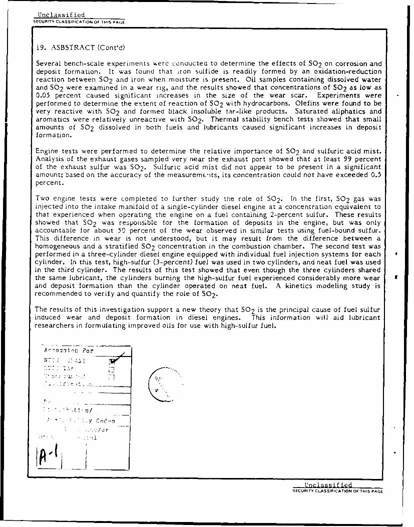
above 1300K. Fig. I shows the effects of pressure, temperature, and fuel/air ratio on the
equilibrium concentration of SO 3 in a mixture of S02 and combustion gases.(2) Note
that the fuel/air ratio scale corresponds with the temperature scale. The flame
temperature was calculated by assuming that the initial temperature was 600°F (316 0 C).
In diesel engine combustion, the pressure is very high, which increases the equilibrium
concentration of S03. However, since temperature is the overwhelming effect, it seems
very unlikely that significant S03 concentrations could form in the gas phase within the
combustion chamber. It is important to keep in mind that the combustion process in a
diesel engine is basically a diffusion flame. Diffusion flames burn at the stoichiometric
2
50
nS0 3 SO 2 (g) +1/ 2 02 (g) = O 3 (g)nS02
PS 0 3K-
PS0 P 2
ns0 2
FUEL(CH 1 g.);TO = 600oF
-5
n S0 3
nSO 2 -1.0- -- -- -- ---- P 300 psia
-0.5
OPERATING RANGE
0.1013=200ps
0.0s
1200 14 1600 18 2000 22 2400 FI I i I II I I I I I I i
800 900 1000 1100 1200 1300 1400 1500 1600 KI I I I I I I I
0.01 0.015 0.02 0.025 0.035 F/A
Figure 1. Effect of temperature and fuel/air ratio on theSO 3/502 mole ratio
(The fuel/air ratio scale corresponds with the flame temperaturethat would be achieved assuming homogeneous combustion and
initial temperature of 600°F (316 0 C))
3

fjel/air ratio, i.e., F/A = 0.065, so the actual flame temperature is much higher than
that based on calculations using the overall fuel/air ratio.
The mechanism for the conversion of SO 2 to S03 remains relatively unknown. If, on
one hand, S03 is formed by
SO 2 + 02 = SO 3 + 0
the rate of its production would probably be very slow. This reaction has a high
activation energy because it involves tne cleavage of the strong bond, 118 kcal/mole, in
molecular oxygen; thus, it is very slow at te--peratures below 1500K. On the other hand,
the termolecular reaction of sulfur dioxide with oxygen atoms
SO 2 + 0 + %I = S03 + %
is essentially independent of temperature and increases in rate as the pressure, i.e., the
third body, M, concentration, is raised. Although this reaction appears to be a likely
candidate, it depends strongly on the oxygen atom concentration in the combustion
chamber. Since oxygen atoms are present only when the temperature of the gas is close
to the flame temperatures, i.e., at temperatures in which S03 is very unstable, it is
highly improbable that this mechanism would account for its formation in the bulk gas
phase environment of the combustion chamber.
A similar argument may be made for the reaction of S02 with OH radicals. The reaction
of OH radicals with SO 2 is complex at ambient temperatures and is believed to beimportant in the formation of sulfuric acid in the atmosphere.(3) At flame temperatures
the reaction
SO 2 + OH = S03 + H
is probably very fast because the concentration of OH radicals is much higher than that
of 0 atoms in the reaction zone.
One mechanism that could conceivably account for the formation of S03 in the gas phase
is the diffusion of 0 atoms and OH radicals into the boundary layer on the surface of the
4

cylinder wall. The temperature in the boundary layer next to the surface of the
relatively cold cylinder wall is expected to be less than 1000K. If SO 3 could be formed
in the boundary layer, it would quickly scavenge water vapor and become sulfuric acid.
While such a diffusion mechanism is possible, it is important to note the diffusion rates
are exceedingly slow at high pressures. Hence, the diffusion of radical species into a
lower temperature region would not only be slow, but reactions at high pressures would
be very fast in bringing their concentrations down to equilibrium levels.
For the mechanism of condensation of sulfuric acid on the cylinder wall to be important,
503 must be formed in the gas phase. Based on the discussion above, this f )r nation does
not seem to be highly probable. Aside from a relatively complex catalytic reaction
involving chemisorbed SO? and 02, it is difficult to conceive of a process that could
result in the formation of detectable concentrations of sulfuric acid in the combustion
Thamber of a diesel engine. Therefore, the arguments given above suggest that the ring
and cylinder bore wear in diesel engines is most probably caused by the abundant sulfur
dioxide formed by the combustion of sulfur-containing fuels.
It is known that S0 2 has a high solubility in oils.(4) Since lubricants contain alkali
dispersants, it is possible that both S0 2 and water dissolve in the lubricant film. When
S02 combines with water, it forms an acidic sulfur dioxide hydrate (5) known in loose
terms as sulfurous acid; it is a relatively weak acid that is comparable in strength with
low molecular weight carboxylic acids. Engine tests (1) have shown that cylinder bore
and ring wear increase when naphthenic acids are added to the fuel; it is equally possible
that sulfurous acid could cause similar wear.
Although the literature favors the sulfuric acid theory, it is simply assumed that 503 is
tormed within the cylinder of the engine. Several measurements of sulfur oxides in
diesel exhaust indicate that the conversion of S0 2 to SO3 may range from as little as I
percent to as much as 90 percent. However, this does not prove that SO3 is formed in
the cylinder where corrosive wear takes place. Thermodynamic calculations show that
SO 3 is relatively unstable at higher temperatures and is unlikely to survive the hostile
environment within the combustion chamber. The probability seems to be greater that
SO 3 is formed in the exhaust system. The lower temperature in the exhaust system
favors the formation of SO3 because the equilibrium is shifted in that direction. Also,
the exhaust system is made of steel, and its surface-to-volume ratio is high. Since the
walls are probably coated with Fe 2 0 3 , it is very possible that catalysis plays a role in the
conversion of SO 2 to 503. Hence, high conversions of fuel-bound sulfur to sulfuric acid
do nct seem to originate from within the engine cylinder. In conclusion, it seems that
there is a considerable question about the actual formation of S03 and sulfuric acid
within the cylinder of the engine.
The purpose of the present study is to further investigate the role of sulfur oxides in
wear and deposit formation in diesel engines. The results of this study suggest that
sulfur dioxide (SO2) formed in the combustion of fuel-bound sulfur is the primary cause
of higher cylinder bore and ring wear and deposit formation in diesel engines. This
finding is expected to have some bearing on the course of future research and the
development of lubricants that will more effectively combat the effects of fuel sulfur.
II. OBJECTIVE
The purpose of this study was to use an exploratory approach involving several
individualized experiments to determine the role of sulfur oxide chemistry in the
corrosion-related cylinder bore and ring wear and reactions that lead to deposit
formation in diesel engines. Previous studies based on engine tests emphasized
measurements on the effects of sulfur concentration, sulfur type, engine temperature,
etc., and concluded that sulfuric acid formation in the cylinder was the principal cause
of cylinder bore and ring wear. However, an analysis of both the chemical and the diesel
engine literature suggests that sulfuric acid may play only a relatively minor role and
that the very abundant oxidation product, sulfur dioxide, could well be the chief cause of
wear and deposit formation in diesel engines. This conclusion implies that future studies
on cylinder bore and ring wear in diesel engines operating on high-sulfur fuels should
consider sulfur dioxide as the corrosive agent rather than sulfuric acid.
I!L APPROACH
This program was carried out from an exploratory stand point to determine the
importance of sulfur dioxide chemistry in wear and deposit formation in diesel engines.
Several experiments including both bench-scale type and full-scale engine tests were
performed. Bench-scale experiments were carried out to determine the reactivity and
6
solubility of S02 in lubricants; wear measurements were made on lubricants contami-
na,..d with moisture and S0 2 using a BOCLE rig; and JFTOT tests were carried out to
determine the effects of 502 contamination on the thermal stability of fuels and
lubricants.
Measurements were made in a Petter diesel engine to determine the in-cylinder
conversion of fuel sulfur to sulfuric acid mist. These measurements were performed
using both sulfur-containing fuels and by adding sulfur dioxide to the air supply to the
intake manifold of the engine. In 60-hour, full-scale engine tests, the effects of fuel
sulfur and S0 2 added to the intake air on wear and deposits were evaluated. A DD 3-53
three-cylinder diesel engine equipped with individual fuel injection systems for each
cylinder was used to determine if contamination of the lubricant with sulfur-containing
combustion products was the sole cause of wear and deposits. In this test, a high-sulfur
fuel was used in two cylinders and a neat fuel was used in the third cylinder. All three
cylinders shared the same lubricant.
Although all the experiments described above had a similar goal, i.e., to show the
potential of S0 2 to cause wear and deposits, the particular experimental procedures and
apparatus used in the various areas of exploration were quite dissimilar so they are
presented in the results section of this report.
IV. RESULTS
A. Engine Tests
There were basically three objectives of the engine testing; the first was to determine
the importance of sulfuric acid in the wear mechanism, the second was to determine the
importance of fuel-bound sulfur in the formation of deposits, and the third was to
determine if the deposit formation and wear were the result of contaminants in the
lubricant or caused by the relatively nascent combustion products formed in the cylinder.
The approach used to determine the importance of sulfuric acid was to measure its
concentration in the exhaust gases of a Petter diesel engine. Some of the earlier studies
showed conversions of fuel-bound sulfur to sulfuric acid ranging from 10 to 90 percent,
others report much lower yields, and thermodynamic calculations indicate that little or
no sulfuric acid should form in the combustion chamber. To accomplish the second
7

objective, tests were performed in a Petter diesel engine to measure the deposits and
wear that result from the sulfur dioxide formed by the combustion of fuel sulfur.
In this test, a sulfur-free JP-7 fuel was used, and sulfur was introduced to the engine by
injecting a flow of sulfur dioxide into the intake manifold. The purpose of this
experiment was to eliminate possible effects of organic sulfur and to determine the
importance of sulfur dioxide in the formation of deposits. To reach the third objective,
tests were carried out in a Detroit Diesel (DD) 3-53 three-cylinder diesel engine
equipped with individual fuel pumps and injection systems on each cylinder. In one
cylinder, a blend of JP-7 fuel and tert-butyldisulfide containing 3-percent sulfur was
used. Since all three cylinders shared the same oil sump, differences in wear and
deposits among the three cylinders were attributed to the sulfur-containing combustion
products formed in the cylinder.
B. Sulfuric Acid Measurements
An analytical method was developed to measure the concentrations of sulfur oxides in
the exhaust of a Petter diesel engine. Fig. 2 shows the apparatus used in these
measurements. Basically, the method consisted of passing the exhaust gases through
Trap A, filled with water, followed by Trap B, filled with 0.15 normal ammonium
hydroxide. Each of the traps was equipped with impingers to enhance the dissolution of
gases in the aqueous media. The volume of gas passed through the traps was measured
with a wet test meter. Even though the object was to measure the relative
concentrations of 502 and sulfuric acid mist, it was important to measure the volume
and know that enough gas had passed through the traps. In theory, all the sulfuric acid
mist is absorbed in Trap A; some of the S0 2 remains in Trap A also, but most of it is
fixed in Trap B containing ammonium hydroxide.
The samples from the traps, each about 20 mL in volume, are analyzed for sulfite ion,
S03, and sulfate ion, 504, by an ion chromatograph. The analysis must be performed
promptly. If the samples are permitted to stand for any length of time, some of the
sulfite ions will be oxidized to sulfate ion, and the sample will then have a falsely high
level of sulfuric acid mist. This oxidation may be why unusually high levels of sulfuric
acid have been found in exhaust samples in previous studies. The present study has
shown that extreme care in preventing the oxidation of the sulfite ion is essential.
s

*flr
Figure 2. Apparatus for trapping out sulfur oxides fromdiesel exhaust
Several bench-scale tests (see apparatus in Fig. 2) \&ere male using mixtures of air and
SO 2 to determine the accuracy of the method. The method provided a good measure-
ment of the total sulfur oxides present in the air sample. In other words, it was apparent
that all the S0 2 was absorbed by the water and aumnonium hydroxide in the traps. Since
the air sample contained only S02, it was hoped that only sulfite ion would be detected
in the water trap. Unfortunately, a significant aimount of sulfate ion was also found,
indicating that some sulfite oxidation had occurred in Trap A before the solution could
be analyzed with the ion chromatograph.
Since the priinar purpose of this measurcment was to determine the sulfuric acid
content of diesel engine exhaust, special steps were taken to prevent the oxidation of
sulfite ion in the water trip. In a recent study, [r', in (5) found that several low
inolecular weight carboxylic acids were, in fact, quite effective inhibitors of the
oxidation of sul fi te ion; glycoli I cid w f ound to I)" a parti,-ularly strong inhibitor.
Irwin's measirermmnts sho'xed that a ri.4-percent ,trud0Js of gi ycolMic a1(ici was optimal in
preventing the oxidation of sulfite ion. It \as found th at tI' replacemrent of the water
in the first trap with thme glcolic ai:id ,olutton grm' t I .e diced the oxidation of sulfite
9

ion. While this change significantly improved the measurement, it was, nevertheless,
important to use every method possible to reduce the rate of oxidation of sulfite ion in
the first trap.
Trial analyses were performed on S02/air mixtures to determine if purging the contents
of Traps A and B would lower the rate of oxidation of sulfite ion in Trap A. TABLE 1
gives some typical data obtained in these analyses.
TABLE 1. Analysis of Sulfur Oxides
Sample Trap A Trap B Air Purge, N2 Purge, % SulfurNumber 503 S04 S03 504 liters liters as H 2SO4
1 171 25 216 0 0 0 5.11
2 78 1 400 29 10 0 0.17
3 31 23 400 1 20 0 4.25
4 21 10 494 11 30 0 1.56
5 26 18 458 9 0 20 2.96
The purpose of purging the traps with air and nitrogen was to drive the dissolved S02 in
Trap A into Trap B. Since sulfite ion is easily oxidized, lowering its concentration in
Trap A would help to prevent the formation of sulfate ion. The results in TABLE I show
that there was considerable oxidation of sulfite ion in Trap A. Only sample 2 gave an
acceptably low level of sulfuric acid. Purging the solution with air and/or nitrogen had
little effect on the yields of sulfuric acid. Note also that there was considerable scatter
in these measurements.
While investigating these results further, it was realized that most of the oxidation in
the samples occurred in the time that lapsed between acquiring the sample and
performing the analysis with the ion chromatograph. In the procedure used, the samples
from Traps A and B were poured into glass vials and carried to another laboratory for
ion chromatographic analysis. The vials contained air in the vapor space above the
solutions taken from Traps A and B. If the samples stood for any length of time before
the analysis was performed, dissolved oxygen in the solution would oxidize the sulfite
10

ion. Therefore, purging with an inert gas such as nitrogen could have been very
beneficial since it would tend to displace the dissolved oxygen in Trap A.
In subsequent trial analysis of S02/air mixtures, the samples in Traps A and B were
purged with nitrogen, and a new technique was used to minimize contamination with
oxygen when the sample was taken from Trap A for analysis. A syringe with a 0.45-
micron uniflo filter was used to extract the sample from Trap A. The syringe and filter
assembly shown in Fig. 3 was particularly useful in retrieving diesel exhaust samples
from Trap A because that sample was grossly contaminated with soot. The soot had to
be removed before the sample could be analyzed with the ion chromatograph. Since the
syringe was also compatible with the injection port of the ion chromatograph, this
method of transferring the sample eliminated any further contact with oxygen and freed
the sample of particulate contamination.
Figure 3. The syringe and 0.45-micron uniflo filter device used toretrieve dissolved diesel exhaust samples from Trap A in Fig. 2
A last question that arose in the analysis technique was the possibility that the
concentration of oxygen in the gas samples might have an effect on the oxidation of
sulfite ion to sulfate ion while the gas was being purged through Trap A. To address this
concern, gas blends of nitrogen and 502 containing 5-percent and 21-percent oxygen
were prepared and analyzed in duplicate. It was found that the conversion to sulfuric
acid was 0.53 percent in the sample containing 5-percent oxygen and 0.38 percent in the
sample containing 21-percent oxygen. These measurements showed that the concentra-
tion of oxygen in the sample had little or no effect on the amount of sulfate ion detected
in Trap A.
The refinements in the technique, along with more prompt analysis, reduced the
oxidation of sulfite ion in Trap A by almost an order of magnitude below the first
11

attempts to analyze sulfur oxides and, thus, greatly improved the accuracy of the
analysis. Several analyses of SO2/air samples provided a baseline that could be used to
compare with analysis of actual diesel exhaust. Obviously, the SO2 /air samples did not
contain any S03 or H2SO4 , but the results still showed that about 0.5 percent of the
sulfur was present in the form of sulfuric acid. A GC-Mass Spectrometric analysis
showed that the SO2 used in this study contained less than 100 ppm of SO3 . Hence, it
was concluded that if sulfuric acid was actually present in the exhaust of the Petter
engine, the exhaust analysis method described above would have to show a conversion of
fuel sulfur to sulfuric acid greater than a baseline value of 0.5 percent.
As mentioned above, a Petter Model PHIW single-cylinder, four-cycle, direct injection,
water-cooled diesel was used in the study of exhaust sulfur oxides. Petter engine
characteristics are given in TABLE 2.
TABLE 2. Petter PHIW Engine Characteristics
Displacement 659 cm 3 (40.2 CID)
Bore and Stoke 87.3 mm x 110 mm
Compression Ratio 16.5:1
Piston Aluminum
Piston Rings 3 Rectangular Compression Rings,I Oil Control
Oil Capacity 2.84 L (no oil filter used)
Before each test was performed, the liner was honed and the piston cleaned to remove
deposits, and the engine was rebuilt with new piston rings. Following a short break-in
on neat JP-7 fuel, the engine oil (polyalphaolefin) was changed, and the test was
started. The test procedure consisted of 60 hours of steady-state operation, accumu-
lated 8 hours per day for 7.5 days with a 16-hour overnight shutdown each day. Typical
engine operating conditions used in most of the tests are given in TABLE 3. Engine oil
level was adjusted to full at the end of each day, and a small sample of the used oil was
drawn for wear metals analysis.
12

TABLE 3. Petter Engine Operating Conditions for Exhaust Analysis
Operating Condition Setting
rpm 1800
Load, ft-lb 28 to 29
Bhp 9.6 to 9.8
Oil Temp, oC 74 to 78
Coolant In, Temp, °C 80
Coolant Out, Temp, °C 82 to 83
Exhaust Temp, °C 550 to 575
BSFC, lb/BHp hr 0.387 ± 0.005
PLston Temperature*, °C
Top Land (thrust and antithrust) 182
Skirt Top (thrust and antithrust) 131
* Determined by temperature-sensitive plugs.
At first, the engine was operated on a JP-7 fuel containing 1.0-percent sulfur added in
the form of tert-butyldisulfide (TBDS). Later the fuel sulfur content was increased to
2.0 percent, and, in some of the tests, JP-8 was used as the base fuel instead of JP-7.
The exhaust samples were taken as close as possible (ca. 6 in. (15 cm)) to the exhaust
port of the engine to minimize the low-temperature gas phase oxidation of S02 in the
exhaust line. The results of repeated measurements at the operating conditions given in
TABLE 3 are shown in TABLE 4. Note that the calculation of wt% sulfur in the form of
sulfuric acid was performed by dividing the moles of sulfur in the form of sulfate ion in
Trap A by the total moles of sulfur in Traps A and B, and multiplying by 100.
It is apparent that the levels of sulfuric acid in the exhaust are very low. When the
baseline of 0.5-percent conversion to sulfuric acid is compared with the average value of
0.81 percent from exhaust measurements, the difference, 0.31 perce.t, 'Ics well within
the standard deviation of the baseline measurements, so it seems that there is virtually
no sulfuric acid in the exhaust. In addition to the measurements near the exhaust, some
measurements were also made about 6 feet downstream in the exhaust. These
13

TABLE 4. Analysis of Sulfuric Acid in Exhaust
Sulfite Ion, mg/L Sulfate Ion, mg/L % Sulfur*Trap A Trap B Trap A Trap B as H2 SO4 Acid
160 782 13.4 106 1.07
110 754 8.8 156 0.73
31 680 9.0 60 0.98
29 580 6.0 112 0.71
66 992 9.9 34 0.75
20 944 4.9 56 0.40
223 958 9.1 41 0.62
12 566 7.3 73 0.94
10 1523 21.3 53 1.11
12 1058 10.1 107 0.72
* The wt% of sulfur as sulfate ion in Trap A. Average = 0.81 percent.
measurements showed conversions to sulfuric acid ranging from 2 to 4 percent,
indicating that there was some oxidation of S02 to S03 in the exhaust gases. In previous
studies, measurements of sulfur oxides in the exhaust showed relatively high conversions
to sulfuric acid. In view of the results of the present study, it appeared that the high
conversion rates observed in previous studies were either caused by 503 formation in the
exhaust system, or they may possibly have been the result of problems with the method
of analysis.
Most of the measurements of sulfur oxides were made using the operating conditions
given in TABLE 3, i.e., the same conditions used in an earlier study by Frame.(1)
However, some work was done at different operating conditions, varying coolant
temperature and load. Several studies (4,6) have shown that operating conditions such as
load and, especially, coolant temperature have a more marked effect on cylinder bore
and ring wear when sulfur is present in the fuel. For example, lowering the coolant
temperature normally reduces the wear rate, but when sulfur is present, the wear rate
tends to increase considerably. These observations have led workers to believe that
lowering the coolant temperature increases the formation of sulfuric acid in the
combustion chamber. If sulfuric acid concentrations are increased as the result of lower
14

combustion temperatures and reduced temperatures at the cylinder walls, it is possible
that this increase would also be observed in the exhaust gases.
Engine tests were performed at coolant outlet temperatures as low as 110°F (43 0 C), and
the exhaust gases were analyzed for SO2 and sulfuric acid content. Tests were also
carried out to determine the effects of rpm and load on the conversion of fuel sulfur to
sulfuric acid in the exhaust gases. All these measurements gave basically the same
result. There was no detectable sulfuric acid in the exhaust.
These measurements are quite conclusive in that they show that very little, if any,
sulfuric acid is formed in the combustion chamber of a continuously operating diesel
engine. Since sulfuric acid concentrations in the combustion chamber appear to be
exceedingly low, the results suggest that sulfur dioxide plays a more important role in
cylinder bore and ring wear. This is not to say that sulfuric acid is totally unimportant in
cylinder bore and ring corrosion. In cases where the engine has been turned off, the
remaining combustion condensates left in the cylinder contain sulfur oxides in aqueous
solution that would most probably oxidize to sulfuric acid.
C. Effects of Sulfur Dioxide
Both engine tests and bench-scale experiments were performed to determine the role of
sulfur dioxide in deposit formation and wear. Two full-scale 60-hour engine tests were
performed in which sulfur dioxide gas was introduced into the intake air stream of the
Petter engine. In these tests, the 3P-7 fuel, the polyalphaolefin lubricant, and the
operating conditions given in TABLE 3 were the same as those used by Frame (1) in a
previous study. These conditions were used because the objective was to compare the
results of adding 502 to the inlet air with the results obtained by Frame (I) on JP-7 fuel
with various added sulfur compounds. The concentration of S0 2 in the inlet air was
made equivalent to that which would be formed in an engine burning a fuel containing 2-
percent sulfur.
In addition to the measurements of engine wear and deposit formation performed by
Frame, samples of the inlet air and exhaust gases were analyzed for sulfur oxides,
including sulfuric acid. Also an iron coupon was placed in the crankcase of the engine.
At the end of the test, the iron coupon was examined for corrosion using electron
15
microscopy. The coupons were then compared with bench-scale corrosion experiments
using similar iron coupons. The results of these measurements are discussed in the
section of this report that addresses corrosion chemistry and mechanisms.
While the tests were in progress, gas samples were taken for analysis of sulfur oxides
from both the air inlet to the engine and the exhaust port. It is well established in the
results presented previously that sulfuric acid is negligible in the combustion of fuels
containing sulfur. However, it was thought that there might be more significant
formation of sulfuric acid in an experiment where the SO2 was in the air before it
reached the combustion chamber. TABLE 5 gives the results of the analysis of samples
taken while the tests were in progress.
TABLE 5. Ion Chromatographic Analysis of Inlet and ExhaustGases for S0 2 and SO 3 in Petter Engine
% SulfurSample Sulfite, mg/L Sulfate, mg/L as SO4
No. Trap A Trap B Trap A TrapB in Trap A
El 310 6600 140 45 1.65E2 500 4200 75 80 1.38E3 640 8000 125 170 1.17E4 650 7200 120 120 1.24E5 690 8000 50 195 0.47E6 760 8900 100 170 0.84E7 680 8200 100 110 0.92E8 810 8500 90 125 0.79E9 990 8300 80 40 0.71EIO 960 8100 88 165 0.79Eli 650 6800 89 140 0.97
1I 490 8300 30 245 0.2812 620 8000 31 435 0.2913 620 7800 31 425 0.2914 440 8100 80 565 0.73I5 670 10000 40 320 0.3016 650 8600 35 390 0.3017 1030 8400 35 215 0.3018 620 6700 45 160 0.50
E = exhaust sample; average = 0.99-percent conversion to H2SO4 .
I = air intake sample; average = 0.37-percent conversion to H2 50 4.
16

The results in TABLE 5 reconfirm that only a small amount of sulfuric acid is formed in
the combustion chamber. In this test, the 502 was given a greater opportunity to
oxidize the 503 than in the tests using fuel-bound sulfur. The concentrations of sulfuric
acid in the exhaust are similar to previous tests; 0.81-percent conversion of sulfur to
sulfuric acid in the test using fuel-bound sulfur and 0.99-percent conversion in the test
where SO2 was introduced into the intake air stream. The analysis of the SO 2 -
contaminated intake air provided an excellent baseline for the sulfuric acid formed in
the process of performing the analysis. Accounting for the baseline, these results
indicate that the amount of sulfur in the form of sulfuric acid in the exhaust, near the
exhaust port, is less than 0.6 percent. This result places considerable doubt in the theory
that sulfuric acid is solely responsible for corrosive wear in diesel engines operating on
fuels containing sulfur.
Upon completion of the test, the engine was disassembled and examined for wear and
deposit buildup. Ring wear was measured, and a standard Coordinating Research
Council (CRC) weighted total deposit piston rating was performed. The used oil was
analyzed for degradation and contamination buildup using standard ASTM tests. Deposits
were washed from the piston and intake valve with heptane and then dimethylformamide
(DMF). Heptane- and DMF-soluble deposits were recovered using a vacuum rotary
evaporator to remove the solvents. The deposits from the heptane and DMF washings
were then weighed and analyzed to determine their chemical compositions.
TABLES 6, 7, and 8 summarize the engine test results and give a comparison with
previous test results reported by Frame (1) using JP-7 fuel and various added sulfur
compounds. Engine wear was evaluated based on used oil iron content and measured
piston ring end-gap change; cylinder liner wear was not discernible among the tests.
Fig. 4 shows the history of iron buildup in the used oil of Tests I and II. Two tests were
performed because the used-oil iron content appeared to be unusually low in the first
test. The irregular, but, for the most part, monotonic increase in the used-oil iron
content is typical of other wear studies. Comparison of data in TABLE 6 shows that the
average used-oil iron content measured in Tests I and II was about 51 percent of that
found in previous tests using JP-7 fuel containing 2-percent sulfur. Based on the work of
Frame, the used-oil iron contents of Tests I and II were similar to or just slightly above
the values that were found for the same JP-7 fuel containing I-percent sulfur.
17

TABLE 6. Petter Engine Tests - 2% Fuel S
Fuel JP-7 JP-7 + 2% S JP-7 + 2% 5 3P-7 + 2% SHeteroatom Type None* as Fuel as SO2 as SO2
Additives* Test I Test IIRange
Avg. Operating ConditionsTest Hours 60 60 60 60rpm 1800 1800 to 1806 180 1803Load, lb-ft 29 29 to 30 29 29Bhp 9.8 9.8 to 10.1 9.9 10.0Oil Temp, °C 79.1 74.4 to 79.1 75.1 76.1Exhaust Temp, °C 605 584 to 624 563 552Oil Consumption, lb/hr 0.228 0.229 to 0.346 0.213 0.362ResultsUsed Oil Fe, ppm 52 231 to 268 146 162Ring End Gap Change, in.
Top 0.001 0.001 to 0.006 0.003 0.0022 0.001 0.006 to 0.016 0.004 0.0063 0.003 0.008 to 0.013 0.005 0.006
Avg. Ring Gap Change, in. 0.0016 0.006 to 0.010 0.004 0.0047Piston WTD Rating 151 222 to 245 240 212Piston Lacquer Demerit 3.2 3.5 to 5.5 7.7 6.8Ring Sticking None None None None
* Test results from Frame.()
TABLE 7. Petter Piston Deposit Composition - 2% Fuel S
Fuel JP-7 JP-7 + 2% S JP-7 + 2% S JP-7 + 2% SHeteroatom Type None* as Fuel as 502 as S02
Additives* Test I Test IIRange
Piston/Int ValveDeposit AnalysesHeptane-Soluble Deposit,
wt g 1.75 1.63 to 2.52 0.27 1.89Composition, wt%
C 85.4 85.1 to 85.3 83.3 84.7H 14.1 14.3 to 14.4 6.6 13.2N 0.11 0.14 to 0.42 0.98 0.23S 0.12 0.17 to 0.56 2.7 3.06
Dimethylformamide (DMF) -
Soluble Deposit, wt g 0.74 0.92 to 1.60 1.08 1.15Composition, wt%
C 67.1 53.0 to 59.7 65.6 64.9H 5.0 5.0 to 8.4 4.8 4.2N 3.9 1.1 to 5.6 3.6 3.3S 0.6 3.1 to 3.8 4.4 3.0
* Test results from Frame.(1)
18

TABLE 8. Used Oil Properties - Petter Engine - 2% Fuel S
Fuel JP-7 JP-7 + 2% S JP-7 + 2% S JP-7 + 2% SHeteroatom Type None* as Fuel as S02 as SO 2
Additives* Test I Test I_Range
Used Oil Analyses
K. Vis, cSt, at 400C 34.32 34.95 to 37.00 34.4 35.3at 100 0 C 6.67 7.39 to 9.30 8.8 7.0
TAN 0.2 0.74 to 1.4 0.90 0.97Insolubles, wt%
Pentane "A" 0.71 0.81 to 1.11 1.54 1.82Toluene "A" 0.53 0.73 to 0.94 1.41 1.72Pentane "B" 0.69 0.81 to 1.10 1.53 1.84Toluene "B" 0.28 0.61 to 0.94 0.74 1.05
ElementsFe,. ppm 52 231 to 268 146 162Cu, ppm 15 20 to 23 <10 <10Pb, ppm <60 <60 <60 60S, wt% < 0.01 0.02 to 0.04 0.04 0.04
Differential IR, Oxidation NILAbsorbance at 1710 cm - 1
* Test results from Frame.(1)
45E 160 0 TEST IC. T 1EST 20. - RON CONTENT 40
140 WM ANT CONSJMED ..
I-5zWJ 120 hJ- 30 :0 100 2 /o) 25 zz 80 00 20 (J
z <6 0 / 1
< 40 - 10 &
20 5
0 0I i *0 10 20 30 40 50 60
TEST DURATION, Hrs.Figure 4. Iron buildup in the lubricant and the consumption of lubricant
during the Petter engine wear tests(Sulfur was added by introducing S02 into air intake stream)
19

One can only speculate on the reason why the wear is much higher when the sulfur is
bound in the fuel. One possible reason is that the combustion process in a diesel engine
is highly stratified, so there are large fuel concentration gradients in the combustion
chamber. When sulfur is part of the fuel, the diffusion-type burning process may result
in relatively high concentrations of SO2 in various regions of the combustion chamber. If
part of the fuel spray impinges on the cylinder wall before it is allowed to burn, it will
evaporate from the wall and burn in a zone relatively close to the wall. This burning
may result in a relatively high partial pressure of S02 near the wall, which would
significantly increase the dissolution of 502 into the oil film.
In a study by Broeze and Wilson (7), it was found that wear in a single-cylinder
Caterpillar diesel engine was nonlinearly dependent on the concentration of sulfur in the
fuel. Their results in Fig. 5 show that there is virtually no difference in cylinder bore
4
M0
M 0
0 0. 1. 1. 2. .
FUEL SULFUR CONTENT, wt%
Figure 5. Effect of fuel sulfur on cylinder bore wear (7)
wear for fuels in the 0- to 0.5-wt% sulfur range. However, bore wear started to increase
substantially as the fuel sulfur content was raised above I percent. Since the
concentration of S02 in the combustion chamber is directly proportional to the sulfur
content of the fuel, and the amount of S0 2 dissolved in the oil film is proportional to the
partial pressure of S02, the fact that there is a nonlinear dependence of wear on sulfur
content suggests that the wear rate may be dependent on the S02 concentration to a
20
power greater than unity. From the standpoint of chemistry, the mechanism of the
corrosion process appears to be a complex reaction involving more than one S02
molecule.
If cylinder bore and ring wear is, in fact, nonlinearly dependent on the SO 2 concentration
in the combustion chamber, it is reasonable to assume that the heterogeneous nature of
the combustion process in a diesel engine would tend to create regions of higher than
normal concentrations of S0 2 , which would, in turn, result in a higher wear rate than if
the S02 was homogeneously distributed in the combustion chamber. For the present, this
explanation is the only one that can be offered for the relatively low wear rates
measured in the engine tests where the source of sulfur is 50 2 in the intake air.
It is well known that fuel sulfur increases the formation of deposits on combustion
chamber surfaces, especially on the piston and the valve tulip. The mechanism of
deposit formation has never been understood, but it has been casually suggested that
deposits form as a result of incomplete combustion and the partial oxidation of
hydrocarbons and sulfur compounds in the fuel.
Comparison of the results given in TABLES 6, 7, and 8 shows that the deposits formed in
Tests I and II are essentially the same as those formed in a similar tests where the sulfur
was bound in the fuel. Piston cleanliness, as determined by Weighted Total Deposit
(WTD), was independent of whether the sulfur was added in the form SO 2 or was fuel
bound. The Lacquer Demerit was a little higher in Tests I and II where S02 was added to
the intake air, but, nevertheless, fell close to the range of values reported by Frame for
fuel-bound sulfur tests. The compositions of the heptane- and DMF-soluble deposits
given in TABLE 8 for Tests I and II were similar to the range of values obtained in tests
with fuel-bound sulfur. The determination of the heptane-soluble deposit in Test I
appeared to be erroneous because the weight of the sample was much smaller than that
found for the base fuel. However, the heptane-soluble deposit weight measured in Test II
was in good agreement with the range of values reported by Frame for fuel-bound sulfur
tests. The sulfur content of the heptane-soluble deposit obtained in Tests I and II was
significantly greater than that of the fuel-bound sulfur tests. There is no explanation for
this other than the fact that the residence time of SO 2 in the combustion chamber was
more than twice as long in Tests I and II.
21

The composition and weight of the DFM-soluble deposits obtained in Tests I and I were
in good agreement with the range of values measured in the fuel-bound sulfur
experiments. Since the DFM deposits are generally considered to be the best indicator
of lubricant thermal stability, the results given in TABLE 7 suggest that sulfur dioxide
plays a major role in deposit formation in diesel engines. For further discussion of the
effects of SO2 on deposit formation, see Section IV.G of this report entitled "The Effects
of Sulfur Dioxide on Lubricants."
The results given in TABLE 8 show that the viscosity and total acid number (TAN) of the
used polyalphaolefin oil samples from Tests I and II fell within the range of values
obtained in the same engine from the fuel-bound sulfur tests. However, the pentane and
toluene insolubles found in the used oils were higher in the samples from Tests I and 1I
than they were in the fuel-bound sulfur tests. The higher concentration of insolubles in
Tests I and II is probably the result of a greater residence time of sulfur dioxide in the
engine. Because sulfur dioxide is present in the cylinder during the compression,
combustion, and part of the intake and exhaust strokes, there is a greater opportunity for
the dissolution of sulfur dioxide and reaction with the oil. For further discussion of the
effects of sulfur dioxide on lubricants see the results of the bench-scale experiments in
Section IV.G of this report.
D. The DD 3-53 Engine Test
The purpose of this experiment was to determine if sulfur-oxide contaminants accumu-
lated in the oil contribute significantly to the wear and deposit formation in diesel
engines. A multicylinder engine with separate fuel-injection systems for each cylinder
was used to compare the wear and deposit formation from a sulfur-free fuel in one
cylinder and a high-sulfur fuel in the other cylinders. Since all cylinders share the same
oil sump, effects of sulfur-dioxide contamination of the lubricant on wear and deposit
formation can be compared with the effects of in-cylinder combustion products.
The engine used in this experiment was an iron block, two-cycle Detroit Diesel, Model
3-53; its characteristics are described in TABLE 9. The engine was fully instrumented
and coupled to a laboratory test stand dynamometer. The test was conducted using the
U.S. Army 210-hour wheeled-vehicle test cycle modified for the needs of this program.
This test cycle, described in TABLE 10, provides alternating periods of full power and
22

TABLE 9. DD 3-53 Engine Characteristics
Engine Type Two-cycle compression ignition, direct injectionunif low scavenging
Weight (dry), kg (Ib) 431 (950)
No. of Cylinders, arrangement 3 in line
Displacement, liter (cu in.) 2.6 (159)
Bore and Stroke, cm (in.) 9.84 X 11.43 (3-7/8 X 4-1/2)
Cylinder Block Material Cast iron (cast iron liners)
Rated Power, kW (Hp) 72.3 (97) at 2800 rpm
Maximum Torque, Nm (lb-ft) 278 (205) at 1800 rpm
Compression Ratio 21 to I
Fuel System Unit injector (N 50 needle valve), primary andsecondary engine filters
Governor Variable speed with throttle controls
Oil Filter Full-flow single filter
Oil Cooling Integral heat exchanger using 100-percentjacket-coolant flow
Piston Description
Material/Design Cast iron/trunk type
Ring Configuration I - Fire ring (rectangular)2 - Compression rings (rectangular)3 - Oil rings
Piston Cooling From jet in top of connecting rod
TABLE 10. Wheeled-Vehicle Test Cycle
Period Time, hr Load, % rpm Coolant, OF (°C)
1 2 100 2400 160 (71)2 1 0 1500 100 (38)3 2 100 2400 160 (71)4 1 0 1500 100 (38)5 2 100 2400 160 (71)6 1 0 1500 100 (38)7 2 100 2400 160 (71)8 1 0 1500 100 (38)9 2 100 2400 160 (71)
10 10 .------------------ Shutdown----------------
23
cold idling with overnight shutdown. A complete description of the wheeled-vehicle test
cycle procedure is given in the Appendix.
Prior to the test, the engine was assembled with new parts, and baseline measurements
were made of the cylinder bore and piston diameters, the piston ring gaps, and the
bearing weights. Each of the three cylinders in the engine was equipped with individual
fuel injection pump systems. A neat Jet A fuel with less than 0.01-percent sulfur was
used in cylinder No. I, and a blend of Jet A and tert-butyldisulfide with a sulfur content
of 3.0 percent was used in cylinder Nos. 2 and 3. With regard to lubricant exposure to
combustion-product contaminants, the fueling of the three cylinders was equivalent to
operating the engine on a fuel containing 2-percent sulfur.
A grade-40 bright-stock lubricant with an API engine service classification SA was used
in the test. The properties of this additive-free lubricant are listed in TABLE 11. While
the test was in progress, small samples of the oil were taken every 7 hours for analysis
TABLE 11. Properties of Grade 40 Lubricant(API Engine Service Classification SA)
ASTMMethod New Oil
Property
K. Vis at 40 0 C, cSt D 445 143.88K. Vis at 100oC, cSt D 445 13.99Viscosity Index D 2270 93Gravity, °API at 60°F D 287 28.6Flash Point, °C D 92 293Total Acid No. (TAN) D 664 0.01Total Base No. (TBN) D 664 0.09
Element, %
Ca XRF* ND**N D 4629 0.012P XRF <0.01S XRF 0.21Zn XRF ND
* XRF = X-Ray Fluorescence.
** ND = Not Determined.
24

of wear metals. Larger oil samples were taken at 70, 154, and 210 hours for a more
complete lubricant quality analysis employing standard ASTM tests. Every time an oil
sample was taken for analysis, the oil level was measured and restored to its original
level. TABLES 12 and 13 give the respective analysis of wear metals and the
determinations of lubricant quality. Fig. 6 shows that both the iron in the used oil and
the consumption of oil increased with reasonable consistency throughout the test. The
rate of oil consumption was calculated from the slope of the line shown in Fig. 6. It is
apparent from the results that the wear rate remained relatively constant throughout
the test and that secondary factors such as the buildup of abrasive particulates had little
or no influence on the rate.
After the test was complete, the engine was disassembled and all the important parts
were gauged according to the standard CRC rating and weight determinations. The
results of these measurements, given in TABLE 14, show that the cylinder Nos. 2 and 3
operating on the high-sulfur fuel experienced substantially more wear and deposit
formation than cylinder No. I, which was only exposed to the combustion products of
neat Jet A. Fig. 7 shows only light scuffing on cylinder No. 1, whereas cylinder Nos. 2
and 3 experienced heavy scuffing, lacquer buildup, and deposits formed in the inlet air
ports.
Bore and ring wear was more than twice as great in cylinder Nos. 2 and 3 than in cylinder
No. 1, but rod-bearing wear appeared to be about the same for all the cylinders. The
combustion environment in cylinder Nos. 2 and 3 appeared to be considerably more
hostile than in cylinder I because the faces of the rings on piston Nos. 2 and 3 were not
only burned but also chipped. Fig. 8 shows the chipping on the edges of the ring faces, as
indicated by the circles.
Compared to piston No. I, piston Nos. 2 and 3 had much higher WTD ratings. These
differences, which were quite substantial, are shown in Fig. 9. While piston No. I showed
only light scuffing, there was heavy lacquer buildup on the skirts and much more carbon
deposition in the land and groove areas of piston Nos. 2 and 3. There is no doubt that the
high-sulfur fuel in cylinders 2 and 3 had a marked effect on piston cleanliness.
25

TABLE 12. Analysis of Wear Elements in the Used Oil
ElementsFe, Cu, Cr, Sp
Hours PPM ppm PPM %
0 <10 <10 <10 0.217 <10 <10 <10 0.21
14 <10 <10 <10 0.21
21 <10 <10 <10 0.21
28 27 <10 <10 0.20
35 ND* ND ND ND
42 35 <10 <10 0.22
49 50 <10 <10 0.2356 42 <10 20 0.22
63 43 <10 32 0.24
70 46 <10 22 0.2477 82 <10 18 0.24
84 85 17 25 0.23
91 87 20 25 0.23
98 77 22 50 0.23
105 85 <10 32 0.22
112 85 <10 47 0.23
119 85 <10 47 0.24
126 120 24 36 0.23
133 145 33 45 0.23140 138 24 28 0.23
147 120 30 42 0.23
154 125 19 27 0.24
161 132 22 30 0.23
168 127 20 27 0.23
175 126 14 18 0.22
182 190 37 40 0.24
189 207 35 37 0.23196 204 21 30 0.26203 199 35 19 0.26
210 212 32 30 0.25
* ND = Not Determined.
Note: All recorded values for Pb were less than 60 ppm; Sn valueswere not determined.
26

TABLE 13. Lubricant Quality Analysis
Test Duration, hr New 70 154 210
K. Vis at 40 0 C, cSt 143.9 125.7 133.9 150.8K. Vis at 100 0 C, cSt 14.0 13.0 14.2 15.5Viscosity Index 93 97 104 105Total Acid No. (TAN) 0.01 0.56 0.47 0.57Tota! Rase No. (TBN) 0.09 <0.01 <0.01 <0.01Insolubles, wt%
Pentane A ND* ND ND 0.63Toluene A ND ND ND 0.57Pentane B ND ND ND 0.67Toluene B ND ND ND 0.51
Carbon Residue, wt% ND 0.46 0.60 0.74Sulfated Ash, wt% ND 0.03 ND 0.06Element
Ca, ppm ND ND ND NDCu, ppm <10 <10 19 27Cr, ppm <10 22 27 31P, ppm <0.01% ND ND 72Pb, ppm <50 <50 <50 <50Sn, ppm ND ND ND 185, %/ 0.21 0.24 0.24 0.24Zn, ppm ND ND ND 14Fe, ppm ND 46 125 212
*ND = Not Determined.
E220 0MOCOTNC0 200 40
180 3.
Z 160I-30 Ld
Z 140
0120 25 (nz
z100 20 0-0 1
15- zZ 60<
< 1022 40
CO 20
0 0
t., 20 40 60 80 100 120 140 160 180 200
TEST DURATION, Hrs.Figure 6. Iron buildup in the lubricant and the consumption of
lubricant during the DD 3-53 engine test
27

TABLE 14. Measurements of Wear and Deposits in theDD 3-53 Engine
PistonNo. 1 No. 2, 3% S No. 3, 3% S
Piston WTD Rating 274.0 335.2 360.0
Cylinder Liners
% Port Restriction 2 12 10
% Scuffed
Thrust 2 3 3
Antithrust 2 22 29
% Total Scuffed 2 12.5 16
% Glazed 0 0 0
% Lacquer 0 100* 100*
Cylinder Liner
Avg Wear Loss, in. (mm) 0.0004 (0.0102) 0.0009 (0.0229) 0.0008 (0.0203)
Piston Ring Wear Loss,in (mm) 0.023 (0.5842) 0.044 (1.12) 0.043 (1.09)
Rod Bearing, gm 0.0635 0.0832 0.0702
Ring Face Condition,% Ring Face Burn
1 5 8** 5**
2 22 7** 14**
3 34 14** 28**
4 24 16"* 50**
Piston Surface Condition
Top Land N N N
Skirt 15% Scuff Heavy Lacquer Heavy Lacquer
Piston Pin N N N
Fuel Injectors and Pump OK Fdiled at 175 hr Failed at 175 hr
Main Bearing, wt loss, gm
1 0.0230 ....
2 0.0483 ....
3 0.0454 ....
4 0.0319 ....
* Heavy Lacquer.
** Chipped.
28

4-A
SO
0-
4-0
4-b
u
29)

- - I
.....------.--n-" --7
a. Rings of piston No. I operated on neat Jet A
2
b. Rings of piston No. 2 operated on Jet A containing 3-percent sulfur
3
c. Rings of piston No. 3 operated on Jet A containing 3-percent sulfur
Figure 8. Condition of the rings in the DD 3-53 engine(Chipping in Figs. b and c are highlighted by circles)
30
a. Piston No. I operated on neat Jet A
AiA,
b. Piston No. 2 operated on Jet A containing 3-percent sulfur(T) (AT)
3 3
c. Piston No. 3 operated on Jet A containing 3-percent sulfur
Figure 9. Condition of the pistons in the DD 3-53 engine
31

The deposit analysis given in TABLE 15 shows that the total deposit weight was about
the same on each of the pistons. On piston Nos. 2 and 3, the heptane-soluble deposits
seemed to be slightly higher and the DMF-soluble deposits were slightly lower than those
of piston No. 1. From the appearance of the deposits on piston Nos. 2 and 3, it would
seem that the DMF-soluble deposits should have been higher than those on piston No. 1.
Perhaps the DMF-soluble deposits on piston Nos. 2 and 3 were less soluble and were not
removed as completely as they were on piston No. 1. Fuel injector deposits were found
to be quite excessive in cylinder Nos. 2 and 3. After 175 hours, the injector fouling was
so severe that a power loss was noticed, and the test had to be momentarily shutdown to
replace the injectors in cylinder Nos. 2 and 3.
TABLE 15. Piston Deposit Analysis
PistonNo. I No. 2, 3% S No. 3, 3% S
Heptane-Soluble Piston
Deposit, gm 0.1658 0.2285 0.2157
Composition, wt%
C ND* ND ND
H ND ND ND
N 0.79 1.15 0.72
S 4.73 13.80 5.71
Dimethylformamide (DMF)Soluble Deposit, gm 0.6581 0.4353 0.5792
Composition, wt%
C 56.84±. 0.07 41.41 42.86 ± 0.16
H 6.22 + 0.02 4.77 4.81 ± 0.07
N 2.18 1.76 1.71
S 9.81 36.40 45.90
* ND = Not Determined.
The sulfur content of the deposits formed on piston Nos. 2 and 3 was substantially
greater than that found in the deposit on piston No. I. The sulfur contents of the DMF-
soluble deposits on piston Nos. 2 and 3 were unusually high; these values were double
checked, but they still seemed unbelievably high. Nevertheless, the trend in the
32

measurements of sulfur in the deposits indicated that significantly mnre sulfur was
incorporated into the deposits formed on piston Nos. 2 and 3 than on piston No. I where
the only source of sulfur was the exposure to the lubricant.
The results suggest that the wear and deposit formation in cylinder Nos. 2 and 3 were
much greater because the partial pressure of sulfur dioxide was much higher in those
cylinders. Not only was the sulfur dioxide concentration higher because it was formed in
the cylinder, its partial pressure was also very much higher than it would have been
anywhere else in the engine because the combustion gases within the cylinder were
highly compressed. The fact that the concentrations of S0 2 in the cylinder are
relatively high seems to best explain the results obtained on cylinder bore and ring wear.
Piston deposit composition seemed to also be influenced by the concentration of sulfur
dioxide in the combustion gases, but the level of contamination of sulfur in the lubricant
seemed to play a role as well. In the course of the DD 3-53 engine test, the lubricant
contained a relatively high concentration (0.24 wt%) of sulfur. In other engines where
much lower levels of sulfur are found in the lubricant, one might expect the deposit
formation to be more dependent on the composition of the combustion gases within the
cylinder.
E. Corrosion Chemistry
The corrosion of metals by acids is a well-known process. Acids react with metals by
two mechanisms; the most elementary of these processes is the displacement of
hydrogen (8), such as
Fe + H2 SO 4 = H2 + FeSO 4
The displacement reaction is a slow reaction compared to the electrochemical effect
that acids have on the oxidation of metals. Basically, rust forms when iron is in the
presence of oxygen, water, and an acidic electrolyte.(9) To understand this mechanism,
it is helpful to envision a multitude of cathodes and anodes arbitrarily assigned to the
surface of the metal. Oxygen is reduced at the cathode
1/2 02 + H 20 + 2 electrons = 20H-
33

and iron is oxidized at the anode
Fe - 2 electrons = Fe +
This corrosion process does not occur unless an electrolyte such as sulfuric acid is
present. When sulfuric acid is the electrolyte, the OH- ions combine with H ions to
make water, and Fe + ions combine with S04 to make iron sulfate. As the corrosion
process proceeds, the H ions are consumed and the pH of the solution increases towards
neutrality.
At first glance, it might be assumed that the oxidation mechanism described above is
solely responsible for corrosive wear of the cylinder bores and rings in diesel engines, and
it may also be conceivable that sulfurous acid entrapped by the lubricant would have an
effect similar to that of sulfuric acid. In aqueous medium, SO2 forms an acidic solution
that is sometimes called sulfurous acid, even though, in the strict sense of the word, that
chemical structure is thought not to exist. Nevertheless, aqueous solutions of SO 2 may
be very acidic and, depending on the concentration, the pH can be as low as 1.6. In that
sense, the corrosion chemistry described above for sulfuric acid is equally as possible for
sulfurous acid.
Actually, the strength of the acid does not seem to be that important in cylinder bore
and ring wear. It has been shown that formic acid is primarily responsible for the
cylinder bore and ring wear in methanol-fueled spark ignition engines.(10-12) On an
equal concentration basis, sulfurous acid is much stronger than formic acid. Since SO2
comprises more than 99 percent of the sulfur oxides formed within the cylinder of a
diesel engine, the concentration of sulfurous acid could easily be more than two orders of
magnitude greater than the amount of sulfuric acid dissolved in the lubricant. In that
light, sulfuric acid should only play a minor role in the corrosion process.
Experiments were carried out to determine the reactivity of sulfurous acid with iron.
These experiments were first performed by placing iron coupons in relatively dilute
aqueous solutions of sulfur dioxide. The test tube was nearly completely filled with the
solution and tightly capped to prevent oxygen from diffusing into the solution. In a 0.1-
percent aqueous solution of SO2 , the reaction with the iron coupon did not behave
anything like the acid-metal reactions described above. Instead of erosion of the metal
34

by the acid, the iron coupon turned black in a few minutes, and the solution became hazy
with what appeared to be a white insoluble substance. The white haze in the solution did
not precipitate, but gradually cleared in about 5 minutes. After about 10 minutes, the
reaction appeared to be complete, and the iron coupon was coated with a black reaction
product. Some of the black product had flaked off the coupon and appeared as a
precipitate at the bottom of the sealed test tube.
The illustration in Fig. 10 shows a striking comparison of a new polished steel ball
bearing with one that was immersed in a 0.1-percent aqueous solution of S02. The black
coating on the ball bearing resembles the iron sulfide coating that is formed in the bluing
of a gun barrel.
Figure 10. Comparison of a virgin steel ball bearing (left) with one thathas been immersed in a 0.1-percent aqueous solution of sulfuric acid
A pH probe inserted into the sulfurous acid solution before the iron coupon was immersed
gave a relatively strong acid pH of 1.7; after the coupon was immersed in the solution
and the reaction was complete, the pH rose to 5.5. It was concluded that the acid had
been consumed and that the solution was essentially neutral.
The coupon was removed from the solution and analyzed for sulfur by X-ray fluorescence
in the Scanning Electron Microscope (SEM). When it was discovered that the black
reaction product contained sulfur, chemical tests were performed to determine the
oxidation state of the sulfur. It seemed reasonably certain that the product was neither
iron sulfite nor iron sulfate, because these salts are relatively soluble in water and the
ferrous forms are colorless except for a slight green tint. Apparently the product was a
sulfide since it was insoluble in water and black in color. The test for sulfide was
performed; a drop of hydrochloric acid was placed on the black deposit, and a piece of
moistened lead acetate paper was held above the coupon to detect effervescent hydrogen
35

sulfide. When a positive test for hydrogen sulfide was found, it was confirmed that iron
sulfide was present in the reaction product.
Continued experimentation was carried out employing gravimetric analytical techniques
to determine more about the composition of the corrosion product. In preliminary
experiments, several samples were examined to gain some insight into the development
of an analytical approach and to determine what measurements needed to be made.
TABLE 16 shows the final result of the gravimetric analysis of two samples of the
corrosion product.
TABLE 16. Gravimetric Analysis of Iron Coupon
Sample A* B C A-C B-C
1 4.6366 4.6241 4.5693 0.0673 0.0548
2 5.3426 5.3330 5.2723 0.0703 0.0607
* A = initial coupon weight, grams; B = coupon weight, grams, after reactionwith SO 2 ; and C = coupon weight, grams, after corrosion product wasremoved by light sanding.
The results in TABLE 16 show that the coupon weight, B, only decreased slightly after
reaction with SO 2 . Since C is the weight of the coupon after the corrosion product is
removed, the value, A-C, is the weight of the iron oxidized by the SO 2 solution. The
value, B-C, is the weight of the corrosion product adhering to the metal coupon. The
remainder of the corrosion product is the insoluble material that flaked off and became a
precipitate at the bottom of the reaction vessel. Additional information given in
TABLE 17 for samples I and 2 include the concentrations of sulfur and iron in solution
and the weight of the precipitated corrosion product.
From the data in TABLES 16 and 17, the weights of iron and sulfur and the total weight
of the insoluble corrosion product can be determined. The weight of iron in the corrosion
product is the difference between A-C and the iron in the solution. The weight of sulfur
in the corrosion product is the difference in the weight of sulfur in solution before the
coupon was immersed, and the weight of sulfur remaining in solution after the reaction
with the coupon was complete. The total weight of the corrosion product is B-C plus the
weight of the precipitate.
36
TABLE 17. Chemical Analysis of Products in Solution and Weight ofPrecipitated Corrosion Product
S Wt of S Fe Wt of Fe Wt ofSample Solution, wt% Solution, g Solution, ppm Solution, g Precipitate, g
1 0.15 0.012 848 0.00678 0.0604
1* 0.26 0.0208 0 0 0
2 0.14 0.0112 793 0.00634 0.061
2* 0.25 0.020 0 0 0
* Same sulfurous acid solution, but without the iron coupon.
Based on the data in TABLES 16 and 17, the corrosion product contains 52.55-percent
iron and 7.45-percent sulfur, with the remainder consisting of oxygen and water of
hydration. Based on that composition, the best fit for the empirical formula appears to
be FeS'FeO'Fe 2O3-6H 20 where the theoretical percentages of iron and sulfur are 52.26
and 7.49, respectively.
The reaction of iron with S0 2 in aqueous solution appears to be an oxidation-reduction
process. In Schilling's (4) review of the literature on sulfur-related corrosion, he gives
mention of some French work by Leboucher (13) and some Russian work by lofa and
Besproskurnov (14) on the reaction of sulfurous acid with iron. They made observations
similar to those reported above, i.e., the reaction involves an oxidation-reduction
process, and they proposed the following overall reaction:
502 + 2H20 + 3Fe = FeS + 2Fe(OH) 2
Based on the composition of the corrosion product as determined in the present study,
the reaction above seems to be highly probable.
In addition to examining the reaction of S02 with iron in aqueous solution, iron coupons
were also immersed in 100-neutral mineral oil containing about 0.1-percent S0 2 and 200
ppm of water. The coupons from these tests were compared with similar coupons that
had been placed in the crankcase of the Petter diesel engine when it was operated on
sulfur-containing fuels and when air containing S02 was inducted. The coupons were
37

examined with a scanning electron microscope equipped with X-ray fluorescence
detection. In the electron micrographs shown in Fig. 11, the light cottonball-like
structures on the surfaces of both coupons represent nonconducting substances that are
most probably metal oxides and sulfides. The X-ray spectrum of these structures showed
the presence of sulfur; the instrument was not capable of detecting oxygen.
Comparing the coupons in Fig. 11 is somewhat confusing because of the factor of 2.5
difference in the magnification of the images, but similarity in the corrosion sites seems
to be reasonably evident.
It may not be that surprising that the appearance of the corrosion sites on the coupon
from the engine are similar to those on the coupon from the bench test. The evidence
given earlier in this report strongly favors SO2 as the principal sulfur oxide in the
exhaust gas. Undoubtedly, SO 2 is equally prominent in the blowby gases that enter the
crankcase of the engine. In the cylinder of the engine, the partial pressure of S0 2 can be
more than an order of magnitude greater than in the exhaust or blowby; it might be
imagined that corrosion on ring and cylinder wall surfaces would be substantially greater
than on the coupon placed in the crankcase of the engine.
F. Wear Tests
In most tribological studies, it has been generally agreed that sulfuric acid is the main
cause of corrosive attack of cylinder bore and ring surfaces in diesel engines that burn
fuels containing sulfur. Examples of these studies include the recent works of Yahagi, et
al. (15) and Lane, et al. (16). Both workers employed relatively advanced reciprocating
wear rigs to examine the effects of sulfuric acid contamination in lubricants on corrosive
wear. Only a few studies, such as the work of Desportes, et al. (17), considered the
possibility that contamination of the lubricant with sulfurous acid (H2 0 S02) could be
important in the corrosion process. Although Desportes, et al. considered sulfurous acid,
they still hold the accepted view that sulfuric acid is the prominent cause of corrosive
wear in diesel engines that combust fuel-bound sulfur.
In the present work, the results suggest strongly that sulfurous acid plays a much more
important role in the corrosion process than has been previously acknowledged. To
further appraise this theory, the change in wear caused by contaminating a lubricant
38

a. Iron coupon from crankcase of Petter engine
b. Iron coupon exposed to 100-neutral oil containing water and S02
Figure 11. Electron micrographs
39

with sulfur dioxide and water was investigated using a Ball-on-Cylinder Lubricity
Evaluator (BOCLE). The BOCLE employs a steel ball that rides on a rotating
-linder. Wear is induced by increasing the load (force) of the ball on the cylirldc.
The lubricity of a lubricant is measured by the diameter of the wear scar that is
produced on the ball. Normally, oil samples are purged with air before the test is begun
because dissolved oxygen increases the wear rate. In effect, the BOCLE measures both
abrasive and corrosive wear. Studies have shown that oxidation of the oil and the
metal at the wear site is an important aspect of the wear mechanism.(_18) It has been
found that there is a significant decrease in the wear rate when all traces of oxygen are
removed from the oil. In the present study, air purging was used in tests of the base oil,
but it was not performed on the oil samples contaminated with SO2 and water. There
were two reasons for this: 1) air purging could drive off part of the dissolved SO2 , and 2)
it might result in increased oxidation of SO2 to sulfuric acid.
In performing these tests, it was important to choose a base lubricant that would not
react with sulfur dioxide. Experiments were carried out on the thermal stability of
various fuels and lubricants contaminated with sulfur dioxide. These tests, described in
the thermal stability section of this report, showed that a 100-neutral oil gave no
evidence of reaction with SO2 and did not form deposits. The 100-neutral oil was an
ideal base lubricant because it was also free of additives that might otherwise
compensate for the effects of dissolved water and sulfur dioxide on wear.
To simulate the composition of the lubricant in a diesel engine, small amounts of S02
and water were added to the base oil. In preparation for the BOCLE tests, a volume of
base oil large enough for several tests was saturated with water. The oil saturated with
water was allowed to equilibrate for a few days to precipitate possible excess water.
Then the oil/water mixture was decanted from the vessel and stored for future use. The
water content of the oil was determined by Karl-Fischer analysis. When an oil sample
containing a lower concentration of water was desired, a portion of the saturated batch
was blended with dry base oil.
The BOCLE tests were done in a timely fashion to prevent unnecessary oxidation of the
dissolved SO2 . Also, for this same reason, the SO2 was added to the oil just prior to the
test. A small portion of the test oil blend was used for sulfur analysis by X-ray
fluorescence.
40

TABLE 18 shows the test results obtained with the BOCLE.
TABLE 18. BOCLE Test Results of Suifur and Water Contents of Base Oil
Run Sulfur, Water, Wear-Scar Test Duration, Load,No. wt% wt% Dia., mm minutes grams
1 0.0 0 0.227 30 1000
2 0.125 382 0.390 30 1000
3 0.125 382 0.385 240 500
4 0.0 0 0.200 240 500
5 0.39 78 0.270 30 1000
6 0.43 518* 0.300 30 1000
7 0.21 259 0.280 30 1000
8 0.0 282 0.235 30 1000
9 0.075 282 0.360 30 1000
10 0.075 282 0.345 30 1000
11 0.070 282 0.325 30 1000
12 0.080 282 0.295 30 1Q00
13 0.085 282 0.290 30 1000
* Water content was above the saturation level.
The test results for Run Nos. I through 7 were performed using the same BOCLE
cylinder, and they were scheduled in the order given in TABLE 18. The most striking
differences between the contaminated oil and the dry-base oil was observed in the first
four runs. Run Nos. I and 2 were done with a load of 1000 grams and Run Nos. 3 and 4
with a load of 500 grams to test for variation in the wear mechanism with load. Since
the wear rate is proportional to the cube of the load, the test durations of Run Nos. 3
and 4 were increased from 30 to 240 minutes. This correlation appeared to agree
surprisingly well with theory and did not indicate any abnormalities in the wear process
because the wear scars obtained in Run Nos. I and 2 were almost identical with the
respective values for Run Nos. 3 and 4.
Comparing Run Nos. I and 2 and 3 and 4 shows that the additions of sulfur dioxide and
water increased the wear scar diameter an average of 82.2 percent of the base oil value.
41

This increase in the wear scar is attributed primarily to sulfur dioxide in the oi.1 since
water by itself appeared to have only a small effect on wear-scar diameter; compare
Run Nos. I and 4 with Run No. 8. Desportes, et al. (17) made similar measurements
with a Pin-on-Disc Friction instrument and found an increase of 25 percent in the wear-
scar diameter when S02 was added to n-dodecane containing the antiwear additive
ZDDP, water, and a succinamide emulsifier. The antiwear additive ZDDP used in their
experiments may have mitigated the effect of SO 2 on the wear process, but nonetheless,
their results generally agree with the present study.
Run Nos. 5, 6, and 7 were made to determine more about the dependence of sulfur
dioxide and water concentration on the wear-scar diameter. It was expected that
increasing the sulfur dioxide concentration would increase the wear-scar diameter.
Contrarily, Run Nos. 5 and 6 seemed to indicate that higher concentrations of sulfur
dioxide decrease the wear scar diameter. This decrease suggests that there may be a
maximum wear scar at some intermediate concentration of sulfur dioxide. An
intermediate concentration of sulfur dioxide was tried in Run No. 7. The result, given in
TABLE 18, clearly shows that there was no marked increase in the wear-scar diameter.
Instead, it appears from the results of Run Nos. 5, 6, and 7 that the wear-scar diameter
became relatively independent of the sulfur dioxide concentration; of course, this
assumes that there is at least some sulfur dioxide in the oil.
Examination of the BOCLE cylinder used in the test revealed that it had a brown
tarnished appearance. This brown tarnished appearance of the iron surfaces was also
observed by Desportes, et al. (17) in the Pin-on-Disc Friction test. It appeared that
corrosion products such as iron sulfide had formed on the BOCLE cylinder and that this
had the effect of increasing the lubricity. This hypothesis seems to agree with the
results from Run Nos. 8 through 13 shown in Fig. 12 where the wear-scar diameter is
plotted versus the run number. It is shown in TABLE 18 that the water contents of the
blends tested in Run Nos. 8 through 13 were each 282 ppm. The oil used in Run No. 8 did
not contain any sulfur dioxide, but each of the subsequent oil samples in Run Nos. 9
through 13 contained about the same amount (0.08 percent) of sulfur in the form of
added sulfur dioxide. Run Nos. 8 through 13 were scheduled in numerical order and they
were started with a new cylinder in the BOCLE. Fig. 12 shows that when the oil is
contaminated with sulfur dioxide, there is a significant enhancement of the wear-scar
diameter, but repeated tests of the same contaminated oil samples tends to decrease the
42

.4
Q
-c
3
i
0
8 9 10 11 12 13
RUN NUMBERFigure 12. Wear-scar diameters plotted for Run Nos. 8 through 13(Data given in TABLE 18; Run No. 8 = base oil; Run Nos. 9 through13 = oil is contaminated with the same amounts of S0 2 and water)
wear-scar diameter. This suggests, as mentioned above, that the corrosion products tend
to improve the lubricity. Metal sulfides, such as MoS 2 , are noted for their lubrication
properties; perhaps these properties are also shared to some extent by iron sulfide.
G. Effects of Sulfur Dioxide on Lubricants
It has been well established that fuel-bound sulfur and nitrogen tend to enhance the
formation of piston deposits in diesel engines. The recent work of Frame (1) showed that
sulfur contributed more to deposit formation than nitrogen. Deposit formation was
strongly dependent on the concentration of fuel-bound sulfur, but it did not seem to be
greatly influenced by the molecular structure of sulfur compounds. Several sulfur
compounds were examined, and only one showed a significant deviation from the
average; the disulfide-type sulfur tended to produce more deposits.
43

In the combustion of diesel fuel, all sulfur compounds are rapidly oxidized to sulfur
dioxide. Since this oxidation is not influenced to any extent by the molecular structure
of the fuel-bound sulfur, and in view of the fact that sulfur dioxide spends more time in
the cylinder than any other known form of sulfur, it would not be surprising to find that
sulfur dioxide is an important precursor to deposit formation. The question of whether
or not sulfur dioxide is important in deposit formation is addressed in this report. The
results discussed below have to do with effects of sulfur dioxide on the deposit-forming
tendencies of diesel engine lubricants.
H. Solubility
The solubility of gases such as oxygen, nitrogen, and hydrogen in hydrocarbons is very
low. For example, only about 100 ppm of oxygen will disso!ve in mineral oil at
atmosDheric conditions. It may be of some surprise then to find that the solubility of
sulfur dioxide in lubricants is several orders of magnitude greater than that of oxygen.
Although the solubility of S0 2 in lubricants is not thoroughly addressed in the literature,
Schilling (4) tacitly mentions that as much as 2-percent sulfur in the form of SO 2 can
dissolve in the oil. Since this statement was not referenced and documented, some
approximate measurements of solubilities were made in four oils. The uils examined
included 100-neutral mineral oil (MO), a polyalphaolefin (PAO), both free of additives,
and two formulated diesel engine lubricants (FLI and FL2).
The solubilities were determined by purging the oil samples with pure sulfur dioxide gas
for a period of about 5 minutes. While the samples were being purged, they were
exposed to a sulfur dioxide pressure of one atmosphere. TABLE 19 gives the results
obtained for the PAO, FLI, and FL2 oil samples. These measurements show that sulfur
dioxide is exceedingly soluble in oils.
The formulated lubricants tend to have a greater capacity for sulfur dioxide, probably
because the additive package contains alkali compounds that neutralize and absorb
acidic substances.
A second method was also used to measure the solubility of sulfur dioxide in oils. Oil
samples were placed in 50-mL flasks and weighed. The oil samples in the flasks were
purged with about 300 cm 3 of sulfur dioxide. They were then weighed again, and the
44

TABLE 19. Solubility of S0 2 in Oils
Test Purged Sulfur, DissolvedOil with S02 wt% SO2, wt%
PAO No 0.01 0.0
PAO Yes 0.78 1.54
FLI No 0.47 0.0
FLI Yes 1.40 1.86
FL2 No 0.55 0.0
FL2 Yes 1.73 2.36
weight gain was taken as the amount of sulfur dioxide dissolved in the oil. The results of
these measurements are given below in TABLE 20.
TABLE 20. Dissolution of 502 in Oils
Dissolved
Test Oil SO 2 , wt%
Polyalphaolefin 0.68
Mineral Oil 0.59
Formulated Oil 0.67
The concentrations found in the second method were lower than those given in
TABLE 19 because the samples were purged with less sulfur dioxide gas, and it was not
possible to ensure a sulfur dioxide partial pressure of one atmosphere during the purging
process.
From the results of the solubility measurements given in TABLES 19 and 20, it may be
concluded that diesel engine lubricants could absorb as much as 2-percent sulfur dioxide
if their partial pressure were one atmosphere. Based on this 2-percent estimate, it is
possible to calculate the approximate amount of sulfur dioxide that could be absorbed by
the lubricant on the cylinder wall of a diesel engine. If the sulfur content of the fuel is
45

2 percent and the compression ratio of the diesel engine is 15 to 1, the calculated partial
pressure of sulfur dioxide in the burned gas with the piston at top dead center is 9.3 mm
of Hg.
Assuming that Henry's Law holds, and it is a fact that the lubricant is able to absorb up
to 2-percent sulfur dioxide with a partial pressure of 760 mm of Hg, the lubricant on thecylinder wall could absorb as much as 244 ppm of sulfur dioxide gas from the combustion
gases. Although this result is ideal in that it assumes an infinite amount of time for theabsorption of gas to take place, it demonstrates, nevertheless, that there is a definite
potential for the absorption of sulfur dioxide by the lubricant on the cylinder wall of a
diesel engine.
I. Reactivity
While examining the solubility of sulfur dioxide in lubricants, it was soon realized that
the additive-free polyalphaolefin oil began to change from a clear to a completely
opaque liquid with a black precipitate. The 100-neutral oil and the formulated lubricants
did not give any visible evidence of chemical reaction. Subsequent experiments with the
polyalphaolefin showed that as little as 0.1-percent sulfur dioxide caused dramatic
changes in the appearance of the oil. Fig. 13 shows the result obtained when a 0.11-
percent blend of sulfur dioxide in polyalphaolefin was heat stressed at 100°C for a periodof 24 hours. The difference between the neat oil and the one treated with sulfur dioxide
is most enlightening in that this seems to be related to deposit formation in diesel
engines.
To investigate the nature of this reaction, some simple experiments were performed to
determine the reactivity of sulfur dioxide with pure organic compounds. The substances
selected for study included decane, -decene, and cumene. Experiments were performed
in the short term by purging the hydrocarbon with sulfur dioxide and looking for animmediate change, and in the long term by capping the vessels and heat stressing them
at 100°C for several days. In the short term, there was no visible evidence of reaction inthe decane and cumene samples. These samples absorbed only about 0.2-percent sulfur
dioxide, which was the amount that might be expected to dissolve. To the contrary, I-decene absorbed about 5-percent sulfur dioxide, and it turned to an opaque reddish-brown
liquid. In comparing the infrared spectra of pure 1-decene with that of the reddish-
46

Figure 13. Samples of neat polyalphaolef in oil(The sample on the left is neat polyalphaolefin oil. On theright, the same oil is treated with 0.11-percent S02. Both
samples were heat stressed at 100 0C for 24 hours.)
brown reaction product, it was very apparent that two new absorption bands appeared at
1121 and 1343 cm - 1 . Bands in this region of the spectrum reflect the presence of
sulfones.(19) Weaker bands at 500, 1185, and 1378 cm -1 were also new, giving further
support that chemical bond formation had occurred between 1-decene and sulfur dioxide.
A strong shift from 1704 cm - I to 1735 cm -1 appeared to occur in the 1-decene spectrum
after it had reacted with sulfur dioxide. This shift also indicated that a significant
chemical change had occurred in the molecule.
Heat stressing of the -decene sample seemed to enhance the reaction that had already
occurred with the sulfur dioxide. In addition to the opaque reddish-brown liquid, a black
gummy deposit was found precipitated in the vessel.
The results show explicitly that the reaction of alkenes with sulfur dioxide was
substantial. This substantial reaction is most probably why the polyalphaolefin oil
reacted with sulfur dioxide. It is highly probable that the polyalphaolefin oil contained
some residual molecules vith double bonds because it was a polymer of -decene.
47

In the long-term heat stress tests, small amounts of black deposit were found on the
vessel wall of the decane sample. An infrared spectrum of the deposit was obtained
using the KBr-pellet technique. The spectrum suggested that the deposit must have been
formed by the reaction of sulfur dioxide with an impurity in the decane because there
were very few absorption bands that were similar to the spectrum of decane. Note the
infrared spectra of 1-decene and the reaction product with sulfur dioxide were very
similar except for the few new bands that were attributed to reaction products.
The heat-stressed cumene sample turned a light-brownish tint, and no formation of gum
or deposit was apparent until after the sample had been in storage for several weeks.
Traces of gum-type deposit precipitated on the the walls of the vessel several weeks
after the heat-stressing period was over.
3. Thermal Stability
The instability of a fuel or oil generally refers to the gums, sediments, or deposits that
can form as the result of a set of complex chemical reactions when hydrocarbon fluids
are stored for a long time at ambient conditions, or when they are thermally stressed
inside an engine.(20) This form of instability generally results from the partial oxidation
of hydrocarbons. However, in the present study, the concern was that sulfur dioxide may
also react with hydrocarbons in the lubricant to form deleterious deposits. To
investigate deposit formation from the aspect of thermal stability, various fuels and oils
were treated with sulfur dioxide and examined in the Jet Fuel Thermal Oxidation Tester
(JFTOT) procedure, ASTM D 3241. In the conventional JFTOT procedure, the test oil is
aerated and then passed over a heated tube to induce oxidation reactions and deposit
formation. Normally, the tube is heated to 500OF (260 0 C) and the test duration is 150
minutes. In the present study, aeration was performed on the neat fuels and lubricants
used to establish baseline data. However, when the fuels and lubricants were treated
with sulfur dioxide, the tests were performed without aeration. This procedure was used
because there was concern that air purging would change the concentration of sulfur
dioxide in the test fluid.
Preliminary experimcnts were carried out at a temperature of 500OF (260 0 C) on a
relatively stable Jr'-5 jet fuel. A conventional JFTOT test on this fuel showed that it
was very stable; the tube deposit rating was a Code I, indicating that there was no
48

visible deposit present on the tube. Note the deposit rating of a JFTOT tube can range
from Code I to Code 4; the greater the deposit the higher the code number. In addition
to the tube deposit rating, there is a filter in the line after the fluid passed over the hot
tube. Sometimes solid matter is formed in the decomposed fluid that does not adhere to
the tube surface and form the deposit that is potentially possible. In that case, the
pressure drop across the filter may be used as an indicator of thermal instability.
When the JP-5 fuel was treated with about 0.1-percent sulfur in the form of sulfur
dioxide, the deposit rating increased to a Code 3; that is, change in the fuel's tendency to
form deposits that could be interpreted as a significant decrease in its thermal stability.
Subsequent tests were carried out on 100-neutral mineral oil, decalin, and the polyalpha-
olefin oil. The results of these tests are given in TABLE 21.
TABLE 21. JFTOT Test Results
Temperature, Sulfur, Deposit FilterTest Fluid OF (°C) wt% Rating Plugging
100-Neutral 500 (260) 0.0 Code 'I NoMineral Oil
100-Neutral 500 (260) 0.11 Code I NoMineral Oil
100-Neutral 600 (316) 0.0 Code I NoMineral Oil
100-Neutral 600 (316) 0.12 Code 2 NoMineral Oil
Decalin 500 (260) 0.0 Code I No
Decalin 500 (260) 0.13 Code 2 Yes
Polyalphaolefin 500 (260) 0.0 Code I No
Polyalphaolefin 500 (260) 0.12 Code 3 Yes
49

The 100-neutral mineral oil was found to be very stable and resistant to attack by sulfur
dioxide. Only at 600°F (316 0 C) did sulfur dioxide affect the stability of this oil. This
reaction was the opposite of that found for decalin and the polyalphaolefin oil; their
stabilities were greatly reduced by the sulfur-dioxide treatment. This is shown in
TABLE 21 by the increase in the deposit rating and by the fact that the fluids containing
sulfur dioxide plugged the filter. For the sulfur dioxide-treated fluids, the filter
plugging occurred in 90 minutes with decalin and in 50 minutes with the polyalphaolefin
oil.
The results of the work show that sulfur dioxide formed in the combustion of sulfur-
containing fuels most probably plays a major role in the formation of deposits in diesel
engines.
V. SUMMARY AND CONCLUSIONS
To gain a better understanding of the role of fuel sulfur in deposit formation and
cylinder bore and ring wear, several bench-scale experiments and full-scale engine tests
were performed. Particular emphasis was placed on determining the importance of
sulfuric acid in the wear mechanism. Thermodynamic and kinetic arguments did not
support the formation of sulfuric acid within the combustion chamber. Hence, one of
the main objectives of this work was to determine experimentally if sulfuric acid is
formed in the diesel combustion process. Also, it was of interest to determine which
fuel sulfur constituents formed in the combustion process cause increased deposit
formation in diesel engines.
A method of analysis was developed to measure the concentrations of sulfur dioxide and
sulfuric acid mist in the exhaust. In developing this analysis technique, a great effort
was made to prevent the oxidation of sulfurous acid, which would lead to a falsely high
concentration of sulfuric acid in the exhaust gases.
Since sulfuric acid has a high probability of being formed in the exhaust line because
temperatures are relatively low, and there is also a possible effect of wall catalysis on
sulfur-dioxide oxidation, gas samples were taken as closely as possible to the exhaust
port of a Petter single-cylinder diesel engine operating on a blend of JP-7 fuel and tert-
butyldisulfide. The analysis showed that very little, if any, sulfuric acid was present in
50

the exhaust; the measurements showed that less than 0.3 percent of the sulfur dioxide
formed in the combustion process was converted to sulfuric acid. It was thus concluded
that sulfuric acid was relatively unimportant, and that sulfur dioxide formed quantita-
tively from the combustion of fuel sulfur was the principal cause of cylinder bore and
ring wear in diesel engines.
Two full-scale engine tests were completed. In the first test, SO2 gas was injected into
the air intake of a Petter engine at a concentration equivalent to that experienced when
operating the engine on a fuel containing 2-percent sulfur. Exhaust gas analysis showed
that less than 0.4 percent of the sulfur dioxide was converted to sulfuric acid during the
combustion process. The test showed that SO2 was responsible for the formation of
deposits in the engine, but was only accountable for about 51 percent of the wear
observed in similar tests using fuel-bound sulfur. This difference in wear is not
understood, but it is speculated that it might result from the difference between a
homogeneous and a stratified SO 2 concentration in the combustion chamber.
The second test was performed in a three-cylinder DD 3-53 engine equipped with
individual fuel injection pump systems for each cylinder. In this test, a neat Jet A fuel
was used in the first cylinder, and a Jet A fuel containing 3-percent sulfur was used in
the other two cylinders. The results of this test showed that even though the three
cylinders shared the same lubricant, the cylinders burning the high-sulfur fuel experi-
enced considerably more wear and deposit formation than the cylinder operated on neat
fuel.
An oxidation-reduction reaction was found to take place between iron and sulfurous acid.
The corrosion products appeared to consist of a mixture of iron sulfide and iron
hydroxide. Based on its iron and sulfur contents, the corrosion product matched most
closely the empirical formula, FeS.FeO.Fe 2O 3 .6H 2 0. Considering the fact that the
concentration of sulfuric acid in the cylinder of a diesel engine is negligible, it is
concluded that sulfur dioxide, which is relatively abundant, is the primary cause of
cylinder bore and ring wear.
A BOCLE was used to determine the effects of sulfur dioxide on lubricity. The results
showed that the contamination of a 100-neutral mineral oil-based lubricant with as little
as 0.05 percent of sulfur dioxide and about 200 ppm of water caused the wear to increase
51
more than 50 percent above the neat base lubricant. It was very evident from these
results that corrosive wear was greatly enhanced by the presence of sulfur dioxide in the
lubricant.
The solubility of sulfur dioxide in lubricants was examined. With a partial pressure of
sulfur dioxide of one atmosphere, the concentration of sulfur dioxide in various
lubricants was found to be in the neighborhood of 2 percent. For a diesel engine with a
compression ratio of 15:1, operating on a fuel containing 2-percent sulfur, the partial
pressure of sulfur dioxide in the combustion chamber, with the piston positioned at top
dead center, is 9.3 mm of Hg. According to Henry's Law, the concentration of sulfur
dioxide absorbed by the lubricant film on the cylinder wall could be as high as 250 ppm.
By combining the dissolved SO 2 with the water that is present in the lubricant, a highly
corrosive medium is pruduced at the surface of the cylinder wall.
Experiments were performed to determine the reactivity of sulfur dioxide with hydrocar-
bons. Olefins were found to be very reactive, forming black insoluble tarlike products;
aliphatics and aromatics were found to be relatively stable in the presence of sulfur
dioxide. The results suggest that hydrotreatment of lubricant base stocks may help to
remove olefinic structures that react with sulfur dioxide and tend to form harmful
deposits.
The JFTOT apparatus was used to determine the effect of sulfur dioxide on the thermal
stability of lubricants. Small additions of sulfur dioxide to a polyalphaolefin oil, which
otherwise had a high thermal stability rating, greatly depressed the oil's thermal stability
and caused considerable insoluble matter to be formed. Similar effects of sulfur dioxide
were observed in experiments with JP-5 fuel and pure compounds such as decalin. The
results of these bench-scale experiments were substantiated in the full-scale engine tests
in which sulfur dioxide was introduced into the air intake of the Petter single-cylinder
diesel engine. In that test, it was shown that the increase in the engine deposits
attributed to sulfur in the fuel was the same as that observed when sulfur dioxide was
added to the air intake. The conclusion is that sulfur dioxide, formed by the combustion
of fuel sulfur, plays a major role in the formation of deposits in diesel engines.
The results of this study support a new theory that 50 2 is the principal cause of fuel
sulfur induced wear and deposit formation in diesel engines. It should be recognized in
52

future work that corrosion by sulfurous acid is a major process affecting cylinder bore
and ring wear in diesel engines operating on high-sulfur fuels.
The results of the present work show that the mechanism of iron corrosion by sulfurous
acid (H 2 SO 3 ) involves an oxidation reduction mechanism, whereas sulfuric acid (H 2SO 4 )
simply behaves as an acid, causing galvanic corrosion. These differences in the
mechanism may suggest new approaches to inhibiting the corrosion process, e.g., new
possibilities may emerge in additives and metallurgy that would not have been considered
if the current belief that sulfuric acid was the principal cause of corrosion continued to
prevail.
The role of fuel-bound sulfur in the formation of deposits has been an important concern,
but the complexity of the problem has suppressed major efforts to investigate the
mechanism. The results of the present study indicate that the problem of deposit
formation may be limited to reactions of sulfur dioxide with the lubricant. With that in
mind, it may be possible to test lubricants based on their reactivity with sulfur dioxide
and, perhaps, reactive components in the oil could be removed by the manufacturer in
the processing stage.
VI. RECOMMENDATIONS
Several studies have examined the effect of fuel sulfur concentration on wear and
deposit formation. It has been shown that the wear rate is proportional to (sulfur)n,
where n is greater than unity. It is recommended that future work should include
experiments to determine the effect of sulfur-dioxide concentration in the inlet air on
wear and deposit formation. If sulfur dioxide is solely responsible for wear and deposit
formation, the dependence on sulfur-dioxide concentration should be the same as that
found for fuel sulfur content.
The reaction of sulfurous acid with iron metal is not well understood. The products of
this oxidation-reduction reaction appear to be FeS and Fe(OH) 2, but little is known about
the mechanism. Future work should include experiments to determine the effects of
temperature and sulfurous acid concentration on the rate of the reaction with an iron
metal surface. The results of such a study may be helpful in explaining the dependence
of fuel sulfur on the cylinder bore and ring wear observed in diesel engines.
53

Further work is recommended on determining the effects of both sulfuric acid and
sulfurous acid on wear. A more quantitative investigation needs to be made to compare
the corrosive wear of lubricants containing equal concentrations of sulfur in the forms of
sulfuric and sulfurous acid.
Vl0. LIST OF REFERENCES
1. Frame, E.A., "Fuel Component and Heteroatom Effects on Deposits and Wear,"Interim Report BFLRF No. 190 (AD A166839), prepared by Belvoir Fuels andLubricants Research Facility (SwRI), Southwest Research Institute, San Antonio,TX, December 1985.
2. Winsor, R.E., "Possible Mechanisms of Unusual Fire Ring Wear: Sulfuric AcidCorrosion."'
3. Anderson, L.G., Gates, P.M., and Nold, C.R., "Kinetics and Mechanism of the GasPhase Oxidation of Sulfur Dioxide Inder Atmospheric Conditions," presented at the193rd National Meeting of the American Chemical Society, Denver, CO, April1987.
4. Schilling, A., "Automobile Engine Lubrication," Vol. 2, Chapter 7, p. 49, ScientificPublications (G.B.) LTD, 1972.
5. Erwin, J., "Organic Acid Inhibitors for SO 2 Oxidation," Final Report No. SwRI-9444/1, April 1987.
6. Weiss, E.K.3., Busenthuer, B.B., and Hardenberg, H.O., "Diesel Fuel Sulfur andCylinder Liner Wear of a Heavy-Duty Diesel Engine," SAE Paper No. 872148,International Fuels and Lubricants Meeting and Exposition, Toronto, Ontario,Canada, November 3, 1987.
7. Broeze, 3.3. and Wilson, A., "Sulfur in Diesel Fuels--Factors Affecting the Rate ofEngine Wear and Fouling," Institution of Mechanical Engineers, Automotive Div.,March 1949.
8. Mack, E., Jr.; Garrett, A.B.; Haskins, J.F.; and Verback, F.H., Textbook ofChemistry, 2nd Edition, Ginn and Company, New York and London, p. 227, 1956.
9. Scully, 3.C., The Fundamentals of Corrosion, Pergamon Press, Oxford, London,New York, Toronto, Paris, and Frankfurt, p. 49, 1966.
10. Naegeli, D.W. and Owens, E.C., "Final Report on Investigation of Alcohol Combus-tion Associated Wear in Spark Ignition Engines--Mechanisms and LubricantEffects," Interim Report AFLRL No. 176 (AD A157714), prepared by U.S. ArmyFuels and Lubricants Research Laboratory, Southwest Research Institute, SanAntonio, TX, December 1984.
54

11. Naegeli, D.W., Yost, D.M., and Owens, E.C., "Engine Wear With Methanol Fuel in aNitrogen-Free Environment," SAE Paper No. 841374, presented at the Society ofAutomotive Engineers Fuels and Lubricants Meeting and Exposition, Baltimore,MD, October 9, 1984.
'2. Naegeli, D.W. and Owens, E.C., "S.I. Engine Cylinder Bore Corrosion by AlcoholCombustion Residues," presented at Spring Meeting, Central/Western States Sec-tion, The Combustion Institute, April 1985.
13. Leboucher, 3., "Les Facteurs Electrochimiquez et Chimiques de La Corrosion
Humide," Metaux et Corrosion, p. 324, 1955.
14. lofa, Z.A. and Besprockurnov, C.G., "Zuru Fiz Khim," 31:(10), p. 2236, 1957.
15. Yahagi, Y., Nagasawa, Y., Hotta, S., and Mizutani, Y., "Corrosive Wear of CastIron Under Reciprocating Lubrication," SAE Paper No. 861599, 1986.
16. Lane, G., Casole, P.G., and Chadwich, R.E., "Development of Marine Lubricantsfor the Future Low and Medium Speed Engines," SAE Paper No. 871396, 1987.
17. Desportes, J.L., Kapsa, P.L., and Martin, J.M., "Corrosive Factor Affecting ZDDPAction," Paper VII (3), Leads Symposium, 1982.
18. Appeidoorn, 3.K., Goldman, I.B. and Tao, F.F., "Corrosive Wear by AtmosphericOxygen and Moisture," ASLE Transactions, 12, pp. 140-150, 1969.
19. Block, E., "Reactions of Organosulfur Compounds," Vol. 37, Monograph Series onOrganic Chemistry, Academic Press, New York, London, Toronto, Sydney, and SanFrancisco, 1978.
20. Baker, C.E., Bittker, D.A., Cohen, S.M., and Seng, G.T., "Research on AviationFuel Instability," NASA Technical Memorandum 83420, 1983.
55

APPENDIX
Wheeled-Vehicle Test Procedure for theDD 3-53 Engine
57

WHEELED-VEHICLE TEST PROCEDURE FOR THE DD 3-53 ENGINE
Instructions
I. Pretest Preparations.
1.1 Filter Elements. Install new element in oil filter and change oil in air filter bath
(using test oil).
1.2 Sump Oil Charge. Charge engine sump to full mark on dipstick with test oil
(AL-16237-L). Close filler cap and motor engine for 1 minute at low speed (about
500 rpm) to fill oil cooler, filter, and internal oil passages. Recheck level and add
to full mark again (should be about 25 lb).
1.3 Priming Fuel System. After changing over to test fuel and flushing fuel lines,
remove the Allen plug from top of primary fuel filter and fill the filter with fuel,
then reinstall plug.
1.4 Break-In Procedure. Set jacket coolant-out temperature controller at 205 0 F.
Start engine and idle at 650 rpm for 5 minutes, then warm up at about 1000 to 1200
rpm for 10 minutes. If no engine malfunctions or leakages occur, conduct the
following break-in and record complete log sheet readings at end of each setting.
Calculate: BHP, Torque, BSFC, and BMEP.
Jacket-OutTime, Speed, Idle, Temperature,
minutes rpm lb OF
30 1800 25 160
30 2100 55 160
30 2300 70 160
30 2400 80 160
1.5 Full-Load Performance Test. Following the break-in run, conduct a full-load
performance test run at the following conditions. Allow conditions to stabilize at
each speed, then record complete log sheet readings at end of each setting.
Calculate BHP, Torque, BSFC, and BMEP.
59
Jacket-OutSpeed Temperature,rpm OF
1400 160
1600 160
1800 160
2000 160
2200 160
2400 160
2600 160
1.6 Valve Clearance Check. Upon completing the full-load performance test, stop
engine and immediately check the hot clearance of the exhaust valves. Adjust
clearances to 0.023 to 0.025 in., also check injector height per gauge.
1.7 Cii and Fuei Change-Over. Upon completing valve clearance check, drain oil
sump and filter. Discard drain and oil filter element. Weigh and record (on oil
consumption log) a new oil filter element. Install new oil filter and then charge
system with full charge of test oil (AL-16237-L) as in Item 1.2. Record weight of
total charge. Change-over to test fuel (AL-16127-F) and flush fuel lines. Replace
both fuel filter elements and prime as in Item 1.3. Weigh oil blowby can and record
(oil consumption log).
1.8 Full-Load Performance Test. Following fuel change-over, run full-load perfor-
mance test as in Item 1.5.
Check and adjust oil level before starting test.
2. Test.
2.1 Warm-Up. At the start of each day--idle for 5 minutes, then start test cycle at
2400 rpm.
2.2 Test Conditions. After warm-up, the following test cycle conditions are followed:
60

Test Cycle for 15 Days
CoolantTime, Load, Temperature,
Period hr_ % rpm OF
1 2 100 2400 ± 20 160
2 1 0 1500 ±25 100± 2
3 2 100 2400 160
4 1 0 1500 100
5 2 100 2400 160
6 1 0 1500 100
7 2 100 2400 160
8 1 0 1500 100
9 2 100 2400 160
10 10 ----------------- Shutdown--------------
Operate at test conditions 14 hours/day for a total of 210 hours. Complete log
sheet readings at end of each period. Calculate: BHP, Torque, BSFC, and BMEP.
2.3 Daily Cool-Down. After the last test hour each day, reduce the speed to idle (600
to 650 rpm) for 5 minutes (without resetting coolant controller), then stop engine.
2.4 Used Oil Samples. Flush oil filter tap, and withdraw a used oil sample during
daily 5-minute cool-down (Item 2.3) according to the Oil Consumption Log schedule
and record sample weight.
Identify each sample as to Test Hours, Test No., and Oil Code (AL-16237-L). Take:
l-oz sample every 7 hours, except at 70 and 140 hours, take 12-oz sample. At end
of test, take 16-oz sample. Take daily oil samples to Chem Lab for elemental
analyses by XRF.
2.5 Oil Additions. New test oil additions, if required, are to be made at the end of
each day after shutdown. Allow 5 minutes for oil to drain back to sump. Add
weighed new oil to restore sump level to full by dipstick. Record weight of add-on
oil consumption log.
61

2.6 Final Oil Drain. Upon completion of post-test power curves and while engine is
warm, drain the sump, saving one gallon of used oil in clean can. Tag can, showing
Test No., Oil Code, Date, and Test Hour. Also remove oil filter element, weigh,
and record.
62
DISTRIBUTION LIST
DEPARTMENT OF DEFENSE CDRUS ARMY TANK-AUTOMOTIVE COMMAND
DEFENSE TECHNICAL INFORMATION CTR ATTN: AMSTA-RG (MR CHECKLICK) ICAMERON STATION 12 AMSTA-TSL (MR BURG) IALEXANDRIA VA 22314 AMSTA-RGP (MR RAGGIO) I
WARREN MI 48397-5000DEPT OF DEFENSEOASD/P&L PROJ MGR, MOBILE ELECTRIC POWERATTN: L/EP (MR DYCKMAN) I US ARMY TROOP SUPPORT COMMANDWASHINGTON DC 20301-8000 ATTN: AMCPM-MEP-TM
(COL BRAMLETTE) ICDR 7500 BACKLICK ROADDEFENSE FUEL SUPPLY CTR SPRINGFIELD VA 22150ATTN: DFSC-Q (MR MARTIN) ICAMERON STATION CDRALEXANDRIA VA 22304-6160 US ARMY GENERAL MATERIAL &
PETROLEUM ACTIVITYDOD ATTN: STRGP-F (MR ASHBROOK) IATTN: DUSDRE (RAT) (DR DIX) I STRGP-FE, BLDG 85-3
ROOM 3-D-1089, PENTAGON (MR GARY SMITH) IWASHINGTON DC 20301 STRGP-FT (MR ROoERTS) I
NEW CUMBERLAND PA 17070-5008
DEPARTMENT OF THE ARMY CDRUS ARMY LABORATORY COMMAND
CDR ATTN: AMSLC-TP-PB (MR GAUL) IUS ARMY BELVOIR RESEARCH, ADELPHI MD 20783-1145
DEVELOPMENT & ENGINEERING CTRATTN: STRBE-VF 10 CDR
STRBE-BT 2 US ARMY RES, DEVEL & STDZN GROUPFORT BELVOIR VA 22060-5606 (UK)
ATTN: AMXSN-UK-RAHQ, DEPT OF ARMY (DR REICHENBACH) IATTN: DALO-PLA (DR WILTSHIRE) I BOX 65
SARD-TR (MS VANNUCCI) 1 FPO NEW YORK 09510-1500WASHINGTON DC 20310-0561
CDRCDR US ARMY RESEARCH OFFICEUS ARMY MATERIEL COMMAND ATTN: SLCRO-EG (DR MANN) IATTN: AMCDE-SS I SLCRO-CB I
AMCDE-WH I P O BOX 122115001 EISENHOWER AVE RSCH TRIANGLE PARK NC 27709-2211ALEXANDRIA VA 22333-0001
CDRDIRECTOR US ARMY TANK-AUTOMOTIVE CMDUS ARMY MATERIEL SYSTEMS PROGR EXEC OFF CLOSE COMBAT
ANALYSIS ACTIVITY PM ABRAMS, ATTN: AMCPM-ABMS IATTN: AMXSY-CM I PM BFVS, ATTN: AMCPM-BFVS IABERDEEN PROVING GROUND MD PM 113 FOV, ATTN: AMCPM-MI13 121005-5006 PM M60 FOV, ATTN: AMCPM-M60 I
APEO SYSTEMS, ATTN: AMCPEO-CCV-S IPROJ MGR, LIGHT ARMORED VEHICLES PM LAV, ATTN: AMCPM-LA-E 1ATTN: AMCPM-LA-E I WARREN MI 40397-5000WARREN MI 48397
BFLRF No. 248Page 1 of 3

CDR CDRUS ARMY YUMA PROVING GROUND US ARMY GENERAL MATERIAL &ATTN: STEYP-MT-TL-M PETROLEUM ACTIVITY
(MR DOEBBLER) I ATTN: STRGP-PWYUMA AZ 85364-9103 BLDG 247, DEFENSE DEPOT TRACY
TRACY CA 95376-5051CDRUS ARMY TANK-AUTOMOTIVE CMD HQPROGR EXEC OFF COMBAT SUPPORT US ARMY TRAINING & DOCTRINE CMDPM LIGHT TACTICAL VEHICLES ATTN: ATCD-SLATTN: AMCPM-TVL I FORT MONROE VA 23651-5000PM MEDIUM TACTICAL VEHICLESATTN: AMCPM-TVM I CDRPM HEAVY TACTICAL VEHICLES US ARMY QUARTERMASTER SCHOOLATTN: AMCPM-TVH I ATTN: ATSM-CDMWARREN MI 40397-5000 ATSM-LL FSD
FORT LEE VA 23801CDR, US ARMY TROOP SUPPORT
COMMAND PROJECT MANAGER.ATTN: AMSTR-E (MR CHRISTENSEN) I PETROLEUM & WATER LOGISTICS4300 GOODFELLOW BLVD ATTN: AMCPM-PWLST LOUIS MO 63120-1798 4300 GOODFELLOW BLVD
ST LOUIS MO 63120-1798PROGRAM EXECUTIVE OFFICE, TROOP
SUPPORT HQ, US ARMY A' IOR CENTERDEPUTY FOR SYSTEMS MGMT ATTN: ATSB-CD-MLATTN: AMCEPO-TRP I FORT KNOX KY 40121ST LOUIS MO 63120-1798
CDRCDR US ARMY LOGISTICS CTRCHEMICAL RD&E CENTER ATTN: ATCL-MSATTN: SMCCR-MUS I FORT LEE VA 23801-6000ABERDEEN PROVING GRD MD21010-5423
DEPARTMENT OF THE NAVYCDRUS ARMY LEA CDRATTN: DALO-LEP I NAVAL AIR PROPULSION CENTERNEW CUMBERLAND ARMY DEPOT ATTN: PE-33 (MR D'ORAZIO)NEW CUMBERLAND PA 17070 P 0 BOX 7176
TRENTON NJ 06828-0176HQ, EUROPEAN COMMANDATTN: 34/7-LJPO (LTC WEIMER) I CDRVAIHINGEN, GE DAVID TAYLOR RESEARCH CTRAPONY 09128 ATTN: CODE 2759 (MR STRUCKO)
ANNAPOLIS MD 21402-5067CDRUS ARMY FOREIGN SCIENCE & TECH DEPARTMENT OF THE NAVY
CENTER HQ, US MARINE CORPSATTN: AIAST-RA-ST3 (MR BUSI) I ATTN: LMM/2FEDERAL BLDG WASHINGTON DC 20380CHARLOTTESVILLE VA 22901
BFLRF No. 2'48Page 2 of 3

CDR CDRNAVAL AIR SYSTEMS COMMAND US AIR FORCE WRIGHT AERO LABATTN: CODE 53632F (MR MEARNS) I ATTN: AFWAL/POSF (MR DELANEY)WASHINGTON DC 20361-5360 WRIGHT-PATTERSON AFB OH
45433-6563CDRNAVAL RESEARCH LABORATORY HQ AIR FORCE SYSTEMS COMMANDATTN: CODE 6180 1 ATTN: AFSC/DLF (DR DUES)WASHINGTON DC 20375-5000 ANDREWS AFB MD 20334
CDR CDRNAVY PETROLEUM OFFICE SAN ANTONIO AIR LOGISTICS CTRATTN: CODE 43 (MR LONG) I ATTN: SAALC/SFT (MR MAKRIS) ICAMERON STATION SAALC/MMPRR IALEXANDRIA VA 22304-6180 KELLY AIR FORCE BASE TX 78241
OFFICE OF THE CHIEF OF NAVALRESEARCH OTHER GOVERNMENT AGENCIES
ATTN: OCNR-126 (DR ROBERTS)ARLINGTON VA 22217-5000 ENVIRONMENTAL PROTECTION AGENCY
AIR POLLUTION CONTROLCG 2565 PLYMOUTH ROADUSMC RDA COMMAND ANN ARBOR MI 48105ATTN: CODE CBAT IQUANTICOVA 22134 US DEPARTMENT OF ENERGY
ATTN: MR ECKLUNDMAIL CODE CE-151
DEPARTMENT OF THE AIR FORCE FORRESTAL BLDG.1000 INDEPENDENCE AVE, SW
HQ, USAF WASHINGTON DC 20585ATTN: LEYSF IWASHINGTON DC 20330
BFLRF No. 248
Page 3 of 3