rohrtest-4 v. 8 - messen nord€¦ · the test system rohrtest-4 allows the computer-aided,...
TRANSCRIPT

ROHRTEST-4 v. 8.8
Tightness test system
for
Sewers, sewage pipes and pipe connections
acc. to EN 1610, SIA 190 / VSA
Separators, Collectors and Shafts
acc. to EN 1610, EN 858-1, EN 858-2, DIN 1999-100, DIN 4040-100,EN 12566-1, SIA 190 / VSA
Drinking water / waste water pressure pipes acc. to EN 805
MESSEN NORD GmbHTightness test systems/ Inspection camerasTest vehicle equipment / Special software
Zum Forsthof 2D-18198 Stäbelow
Tel.: + 49 38207 / 656-0Fax: + 49 38207 / 656-66e-mail: [email protected]: www.messen-nord.de

ROHRTEST-4, v. 8.8 MESSEN NORD GmbH
page 2
0. Table of contents Side
1. Application of the test system 4
1.1. Water pressure-test / low-pressure 51.2. Water pressure-test / high pressure 51.3. Shaft and separator-test in the free-mirror-procedure 61.4. Compressed air-test / sleeve-sample 8
2. Technical parameters 11
3.1. General business-parameters 113.2. Measuring-equipment WATER / water supply 123.3. Measuring-equipment AIR / compressed air-supply 133.4. Measuring-equipment VACUUM / hypotension-production 143.5. Measuring-equipment HIGH PRESSURE / high pressure-production 153.6. Measuring-equipment SHAFT 163.7. Measuring-precision of the measuring-facilities / calibration 18
4. Danger-prevention 20
5. Installation 215.1. Installation 215.2. Installation of the USB-Adapters 225.3. Program-configuration 245.4. Formation of the individual protocol-head 25
6. Test standards and parameters 276.1. Selection of the test procedure and the test standard 276.2. Test with water / low-pressure 286.2.1. Test parameters for tests of DIN EN 1610 28
(Water, low-pressure)6.2.2. Test parameters for tests of DIN 1999-100 29
(Water-level-tests for separators)6.2.3. Test parameters for tests of DIN 4040-100 33
(Water-level-tests for fat-separators)6.3. Test parameters for tests of DIN EN 805 36
(Water, high pressure)6.4. Test parameters for tests with compressed air 376.5. Test parameters for special-tests 376.6. Test parameters for sleeve-tests 386.6.1. Tester administration 396.6.2. Sleeve-test with reference-measurement 406.6.3. Sleeve-tests of ATV/DWA M 143 slices 6 41

ROHRTEST-4, v. 8.8 MESSEN NORD GmbH
page 3
7. Test-transaction 427.1. Tests with measuring-equipment WATER 427.1.1. Preparatory works 427.1.2. Test with measuring-equipment WATER 437.2. Tests with measuring-equipment HIGH PRESSURE 447.2.1. Preparatory works 447.2.2. Test-transaction with measuring-equipment HIGH PRESSURE 457.3. Tests with measuring-equipment AIR 467.3.1. Preparatory works 467.3.2. Transaction of the test with compressed air 47 7.3.3. Test of tube-connections / sleeve-test 487.4. Tests with the measuring-equipment SHAFT 497.4.1. Preparatory works 497.4.2. Transaction of the test with the measuring-equipment SHAFT 50
8. Data-concept 518.1. Storage of the test reports 518.2. Project-administration 528.2.1. Transferred by data-continuances, updating of the project-administration 528.2.2. Summary from test reports to lists and overview-tables 528.3. Preparation and alteration of test report forms 558.3.1. Saving hierachy of test report forms 558.4. Data take over from test reports 588.5. Configuration of the option "GPS" 59
9. Appliance-maintenance, calibrations and function-tests 609.1. Appliance-check 609.2. Cleaning of the filter of the measuring-equipment WATER 609.3. Changeover to winter-business 619.4. Test of the appliance-function, own-control 619.5. Cleaning of the measuring-equipment SHAFT 61
Installation:
Test standards (tabular transcriptions, work-leaves)
A) DIN EN 1610B) LfW 4.3-6C) ATV/DWA M 143-6D) DIN 1999-100 / EN 858-1E) DIN 4040-100

ROHRTEST-4, v. 8.8 MESSEN NORD GmbH
page 4
1. Application of the test system
The test system ROHRTEST-4 allows the computer-aided, automated tightness testof sewage pipelines, muffs, shafts and separators after the test standards nationallybinding for these installations. In the result of the test, standardized test reports areproduced which document the test course and the test result.
You find a complete list of the test-specific system-components under 2. System-components / delivery capacity:

ROHRTEST-4, v. 8.8 MESSEN NORD GmbH
page 5
System-components Test procedures
Control unit, integrated AIR/VACUUM (RT-ST04) This unit is required for all Test procedures,contains measuring-equipment for AIR / VACUUMtests, supplie unit, data-transformers and testcontroller for all measuring-facilitiesTests acc. to EN 1610 (L) i.e.
External measuring equipment AIR (RT-EXTL) External Filling and measuring unit for testing highpipe dimensions, application directly at the pipefastener, makes filling procedure fast and saveTests acc. to EN 1610 (L) i.e.
Measuring-equipment SHAFT (RT-SP04) Shaft and separator-tests acc. to EN 1610,ATV/DWA M 143/6, EN 858-1, EN 858-2, DIN1999-100, DIN 4040-100 i.e.
Measuring-equipment WATER (RT-WA04) Allows water loss tests by automatic supplyingand measuring the lost water. Unit can keep up agiven pressure or a level in connection withexternal sensors.Tests acc. to EN 1610 (W) i.e.
External water pressure sensor(RT-EXTW)
Allows in connection with RT-WA04 the water losstest by keep up the water start level. Apllication ofthe pressure sensor directly at the pipe fastener.Tests acc. to EN 1610 (W) i.e.
External water pressure sensor(nozzle model) (RT-EXTWR)
Allows in connection with RT-WA04 the water losstest by keep up the water start level. Apllication ofthe pressure sensor at the drain outlet.Tests acc. to EN 1610 (W) i.e.
Measuring-equipment HIGH PRESSURE(RT-HD04)
Tests of DIN EN 805 as well as. the former NormDIN 4279 (water, high pressure)
Air-distribution-unit (RT-LV04) Muffs and stand-tests with compressed air afterATV/DWA M 143/6, DIN EN 1610, Control of thetests and blister-pressure for Max. 4 Fasteners aswell as a Junction test fastener
Junction test fastener (RT-MU04) Manually driven reel with connection-management100 m to the Junction test fasteners over only onehose-management with interior-lying main lead formeasuring-sensor, air-control and observation-cameraOptional fade-in of the Test parameter into thevideo-picture

ROHRTEST-4, v. 8.8 MESSEN NORD GmbH
page 6
1.1. Water pressure-test / low-pressure
Configuration A: Water pressure test at the closed system (fastened pipe)
Standards: EN 1610 „W“DIN 1986 Teil 30DWA M 143 Teil 6SIA 190 / VSAÖNORM B2503Special test procedure „W“
Control unitRT-ST04
Measuring unit WATERRT-WA04
Connection cableRT-VK10
Testconnection
Watersupply

ROHRTEST-4, v. 8.8 MESSEN NORD GmbH
page 7
Water pressure-test / low-pressure
Configuration B: Water pressure test at the open system (open water column)
Standards: EN 1610 „W“DIN 1986 Teil 30DWA M 143 Teil 6SIA 190 / VSAÖNORM B2503Special test procedure „W“
Testconnection
Watersupply
Control unitRT-ST04
Measuring unit WATERRT-WA04
Dispatcher boxRT-VBOX
External pressure sensorRT-EXTW

ROHRTEST-4, v. 8.8 MESSEN NORD GmbH
page 8
1.2. Water pressure-test / high pressure
Test standards: EN 805 DIN 4279 (become obsolete) Special test procedure "H"
Control unitRT-ST04
Measure equipment HIGHPRESSURE RT-HD04
High pressure pump

ROHRTEST-4, v. 8.8 MESSEN NORD GmbH
page 9
1.3. Shaft and separator-test in the free-mirror-procedure
Configuration A: Shaft - / separator-test of automatic water-addition
Configuration B: Separator-test with automatic water-addition
Control unitRT-ST04
Measure equipmentWATER RT-WA04
To theShaft
Watersupply
Connectioncable RT-VK10
Dispatcherbox RT-VBX
Control unitRT-ST04
Measure equipmentSHAFT
Sensor cableRT-SK10
Measure equipmentSHAFT RT-SP04

ROHRTEST-4, v. 8.8 MESSEN NORD GmbH
page 10
Configuration C: Separator-test with several level-probes
Test standards: EN 858DIN 1999-100DIN 4040-100EN 1610 "W"Special test procedure „W“
1.4. Pipe test with compressed air / measuring equipment AIR/VAKUUM
Measure equipmentSHAFT RT-SP04
Measure equipmentSHAFT RT-SP04
Control unitRT-ST04 with2 add. Meas.ports
Sensor cableRT-SK10
Measure equipmentSHAFT RT-SP04

ROHRTEST-4, v. 8.8 MESSEN NORD GmbH
page 11
Test standards: EN 1610, Verfahren „L“DWA M 139DIN 1986/30, DWA M 143/6ÖNORM B2503SIA 190 / VSASpecial test procedure „L“
1.5. Pipe test with compressed air / external measuring equipment AIR
Control unitRT-ST04
Air distribution unitRT-LV04
Compressed airsupply

ROHRTEST-4, v. 8.8 MESSEN NORD GmbH
page 12
Test standards: EN 1610, Verfahren „L“DWA M 139DIN 1986/30, DWA M 143/6ÖNORM B2503SIA 190 / VSASpecial test procedure „L“
Compressed airsupply
External measuringequipment AIR
Control unitRT-ST04

ROHRTEST-4, v. 8.8 MESSEN NORD GmbH
page 13
1.6. Compressed air tightness test for pipe junctions
Test standards: ATV/DWA M 139ATV/DWA M 143-6EN 1610ÖNORM B2503SIA 190 / VSASpecial test procedure „L“
Control unitRT-ST04
Video Data BoxRT-DBOX
RT-LV04Compressed aircontrol unit
Compressed airsupply
Junction test reelRT-MU04,house length 100 m,cable, meter counter andvideotextgenerator integrated
Junction testfasteners withintegratredcamera

ROHRTEST-4, v. 8.8 MESSEN NORD GmbH
page 14
1.7. Water tightness test for pipe junctions
Test standards: ATV/DWA M 139ATV/DWA M 143-6EN 1610ÖNORM B2503SIA 190 / VSASpecial test procedure „W“
Control unitRT-ST04
Video Data BoxRT-DBOX
RT-LV04Compressed aircontrol unit
Compressed airsupplyKompressor
Junction test reelRT-MU04,house length 100 m,cable, meter counter andvideotextgeneratorintegrated
Junction testfasteners withintegrated camera

ROHRTEST-4, v. 8.8 MESSEN NORD GmbH
page 15
2. Technical parameters
2.1. General business-parameters for all system-components
Power supply 12V DC (motor vehicle-shelf-net, 16A)230V 50 Hz (6 A)Supply takes place over the control unit ST04
Electric connection 12V: Motor vehicle-socket for included cables230V: Net-socket
External measuring-facilities: Connection to measuring-equipment
over special-cables
Business-conditions Temperature:1 ... 40°C, no direct sun-radiation
Humidity:Control unit until 90 percent of rel. Humiditynot-condensesMeasuring-facilities WATER, HIGH PRESSURE andSHAFT IP65, the function of the measuring-equipmentSHAFT restricted with moisture-effect.
Transportation and camps- Temperature:conditions: 1 ... 60°C, measuring-facilities WATER and HIGH
PRESSURE can through complete emptying of water(business-means), Condensation, or throughreplenishing with motor vehicle-frost-protectionsufficient concentration frost-certainly is done.Humidity:until not-condenses relative humidity 90 percentPackage:Appliance-casings are as transportation-package(Package-service, been not suitable. Additionalprotection against push and pressure necessary.Stack-bar-ness:Appliance-casings are unpackaged until Max. 3Appliances stack-bar.

ROHRTEST-4, v. 8.8 MESSEN NORD GmbH
page 16
2.2. Measuring-equipment WATER / water supply
Operating parameters
Business-medium: Water, fine-filteredEntrance-pressure-area: - 0,1 ... + 0,5 barExit-work-pressure: Max. 1 barExit-pressure-proof-ness: Max. 2,5 bar, over it irreversible damageMaximum-flow: 400 l/h
Water supply
Since the measuring-equipment WATER possesses an integrated pump, only apressure-loose water-connection is required. The entrance-pressure can .0.1 bar. Tosuck in from until tank more deeply situated to 1 m, until +0.5 amount cash (tank liesuntil to 5 m higher than the measuring-equipment).
RESPECT! Infringements of the maximum entrance-pressure can lead toirreversible damages of the appliance as well as to the user'sendangering.
About the capability of the installation not through pressure-garbages in the hose-managements as well as it is recommended to the connections to reduce not toexceed a maximum hose-length of 10 m and a minimal cross-section of 10 mm, notto under-stride.
2.3. Measuring-equipment AIR / compressed air-supply
Operating parameters
Business-medium: AirEntrance-pressure-area: 0,1 ... 2,bar 0 above atmospheric pressureExit-work-pressure: Max. 0,6 barExit-pressure-proof-ness: Max. 1,5 bar, over it irreversible damageMaximum-vacuum-stream: 500 l / min (normal-gas)
Protection against damages through over pressure
The form of the filling control unit is on Max. 2 bar to restrict cash, a form isrecommended by about. 0,5-1,0 bar. The pressure-restriction takes place with amechanical pressure control as well as. Pressure minimizer, which becomes rear forthe compressor.
For the duration of the test operation, the upholding the form is necessary at thecompressed air-entrance of the filling control unit.
RESPECT! Heed section 4 about the danger-prevention with the contact withcompressed air.

ROHRTEST-4, v. 8.8 MESSEN NORD GmbH
page 17
2.4. Measuring-equipment VACUUM / hypotension-production
Operating parameters
Business-medium: AirEntrance-pressure-area: 0,0 ... 1,bar below atmospheric pressureExit-work-pressure: Max. 1,bar below atmospheric pressureMaximum-vacuum-stream: 500 l / min (normal-gas)
Hypotension-production
The production of the hypotension can be gone in for which with customary pressure(so-called ejectors, jet-procedures) with compressed air or water as energy-bearersor but with vacuum-suction pumps takes place.
2.5. Measuring-equipment HIGH PRESSURE / high pressure-production
Operating parameters
Business-medium: WATER, fine-filteredWork-pressure-area: 0 ... 25 barPressure-proof-ness: Max. 40 bar, over it irreversible damage as well as.
Endangering
High pressure-production
The connection to the measuring-equipment HIGH PRESSURE takes placeaccordingly following illustration:
Pressure liniter <= 25 bar
to the test object
to the control unit
High pressurepump

ROHRTEST-4, v. 8.8 MESSEN NORD GmbH
page 18
2.6. Measuring-equipment SHAFT
There are two different test procedures for the use of the ROHRTEST-measurementuipment SHAFT:
a, level-alteration-measurement
On this occasion the level-alteration is recorded opposite the zero-water-stand atbeginning of the test and is calculated the water-loss-quantity with help of the shaft-geometry. The pressure-alteration yielding itself through the level-alteration amountsto at most 5 mbar.
Measuring-area: 50 mm level-alterationAppliance-technology: Control unit ST04,
Measuring-equipment SHAFT
b, water-loss-compensation
With this Test procedures, the water-level is stopped steadily at the zero-water-standover the entire test procedure. The addition of water-losses takes placeautomatically, the loss-installment is recorded over the test procedure.
Measuring-area: 0.02 .. 400 l/h loss-installment (loss of 0 is recognized)Appliance-technology: Control unit ST04,
Measuring-equipment WATER,Measuring-equipment SHAFT
Zero-water-stand
Measuringequipment SHAFT

ROHRTEST-4, v. 8.8 MESSEN NORD GmbH
page 19
The measuring-equipment SHAFT (ROHRTEST SP04) possesses the admissionof the LGA Würzburg for the test of fusible-ness-separators of the PrüfnormDIN in 1999-100.
We like to send you a copy of the certificate on demand.
Technical parameters
Connection: over connection-cables at reason-appliance ROHRTEST 4,Supply with protection-small-tension of the reason-appliance,maximum cable-length 80m
Denseness- DIN EN 1610, method "W"tests: DIN 1999-100
DIN 4040-100DIN 4261-1DIN EN 12566-1Special-tests (free parameters)
Measuring-area: Max. 50 mm level-alterationentspr. Max. 39 l loss of DN 1000entspr. Max. 25 l loss of DN 800
Dissolution: 0.01 mm level-alteration
Precision: +/-0.2 mm with expired or not existing calibration
+/-0.1 mm with valid calibration, See section 3.7
+/-0.03 mm with parallel temperature measurement and validcalibration, See section 3.7
Please heed:The stated measuring-precision is gained by the measuringinstrument under unfavorable conditions only 15 min after positioningand switching on in the span required for this stabilization-processbeing main from the temperature-difference between the place of thestorage as well as the transportation and the place of the usedependent.
Delivery capacity: Measuring-equipment "shaft" with tripod and level unit,extension-tubes 0,5 m and 1,0 m, Calibration report

ROHRTEST-4, v. 8.8 MESSEN NORD GmbH
page 20
2.7. Measuring-precision of the measuring-facilities / calibration
Measuring-equipment
EinstellgenauigkeitTest pressure /level
Measuring-precisionpressure - / level-waste
Measuring-precisionwater-loss
AIR / VACUUM +/- 5 mbar +/- 1 mbar -
WATER +/- 10 mbar +/- 2 mbar 5% from themeasurement in thearea 0,02-400 l/h
HIGHPRESSURE
+/- 200 mbar +/- 15 mbar 5% from themeasurement in thearea 0,02-400 l/h
SHAFT +/- 0,2 mm Up to +/- 0,03 mm
See section 2.6!
-
Calibration of measurement equipments AIR, WATER, HIGH PRESSURE
The measuring-facilities of the system ROHRTEST are basing on high-qualitysensors for pressure and water flow which are subjected extensive tests beforedelivery.In order to support the users of the installation in the proof of the precision oppositeher/its/their clients, all measuring-facilities are calibrated. The Calibration reportsbelong to the delivery capacity of the respective installations.Through the application of DKD-certificated calibration equipment the retracing of themeasurements to the German national norm is given.
A repetition of the calibration is recommended by the manufacturer in distances of 1years, please contact for this purpose your supplier as well as. the appliance-manufacturer.
Influence of the atmospheric pressure on the pressure-measurements
Through this, measuring-proceeding would use, the recorded test pressure remainsindependently from the atmospheric pressure, d.h. Weather-changes, on the agendawind and similar factors don't have any influence on the test result.
Since the water-loss as well as. Pressure-waste from a leaky tube-wall as well as. atube-connection dependent on the difference-pressure of inner and outside-pressureis, the test pressure (inner-pressure) should be put in relatively to the atmosphericpressure (outside-pressure).In order to enable this, the functions "Calibration atmospheric pressure" are existingfor the measurement equipments AIR, WATER and HIGH PRESSURE. Byimplementation of these functions, the exact reference of the test pressure to thecurrent environment-atmospheric pressure is guaranteed directly before beginning ofthe tube-test.

ROHRTEST-4, v. 8.8 MESSEN NORD GmbH
page 21
4. Danger-prevention
Danger by electric stream
The test system ROHRTEST works with a supply of 230V AC why the danger of theinjury of electric electric jolt emerges with improper application.
Run the appliance if you use the 230V-supply, only at as prescribed groundedprotection-contact-sockets!
Use only the included original supply cable ! If these cable is damaged don’t use ituntil professional repair.Replace the electrical fuses only with such with same parameters.
The control unit is not waterproof. The appliance is only allowed in surroundings withfewer than 90 percent humidity (not-condenses).If water penetrated into the device, so another application is forbidden.
The control unit don’t contain any through the user to replacing part / modules.With disturbances of the device function please contact the repair-service.A usage of the device with opened casing (decreased front-plate) is forbidden.
Danger by compressed air
The test with compressed air rescues with improper handling of the devices security-risks for the user.
For the application of the Fasteners (dense-disks) are the application-rules of therespective manufacturers to heed.All fasteners / hoses / connectors are to be checked for sure seat before pressureapplication.
As long as the pipeline is under pressure, present people have to choose her/its/theirresidence so that they cannot be hurt by for example away-skidded fasteners.
Pipeline, hoses and measuring-equipment are to be aired before the solving theconnections.

ROHRTEST-4, v. 8.8 MESSEN NORD GmbH
page 22
5. Installation
5.1. Installation and Starting up
• Put the control unit ST04 on the suitcase-acreage and open the suitcase-cover,
post the suitcase-cover
• Remove the cap from the connection-socket “supply” and connect the supply-cable "230V AC", you bolt the clutch
• Connect the power plug to an as prescribed installed protection-contact-socket
(230V AC)• Switch the main-counter on position in "1", (230V AC) the control-ads "12V DC"
and "24V DC" now must shine, the control-ad "controllers" must with a frequency
of about. 1 Hz blink• Now connect the measuring-equipment, which you want to use, to the connection
"equipment" and proceed, as described in section 7 further

ROHRTEST-4, v. 8.8 MESSEN NORD GmbH
page 23
5.2. Installation of the USB-Adapters
To the installation of the drivers - software must possess you administrator-rightsunder Windows 2000 and Windows XP, there some files into this Windows - system-table is copied. If you don't own any administrator-right, you please turn to the personresponsible for it.
Driver-installation
1.) Put the included CD into her/its/their CD-drive.
2.) Close ggf. the automatically appearing installation-window.
3.) Start the Windows-Explorer and select the CD-drive.
4.) Change 1.1 TO RS232 Converter\PC Driver" into the table "USB.
5.) Double-click the file "Setup.EXES." The installation starts.
6.) Click on "further" and "completing" is finished until the installation.
7.) Connect the USB-Adapter with the computer. Windows installs him/it
corresponding drivers automatically.
8.) Windows recognizes the new hardware automatically and shows hardware
him/it-Installation-assistants
9.) If you choose the automatic installation (recommended), that becomes driver,
installed with the installation-assistant, possibly a latest-Art of the computer is
necessary
More exact operating system-specific instructions are in the included oneTo find (only in English available) installation-instruction on the Treiber-CD.
Configuration of the adapter (Windows - appliance-managers)
1.) Open the system-control (start (attitudes) system-control) and double-click on
"system."
2.) Change "hardware" to the file and choose "appliance-managers."
3.) Open the section "connections COM and LPT" in that you click on the "plus-
sign."
4.) You/they see to Serial adapter (COM x)" a component "USB there, with what
the "x" for the currently assigned Comport - number stands. Select this Comport
in the measuring-software as interface and test the communication with the
connected, switched on appliance in that you start a measurement.

ROHRTEST-4, v. 8.8 MESSEN NORD GmbH
page 24
5.) To altering the Comport - clicks you to Serial adapters (COM x)" number on
the component "USB in the appliance-manager with the right mouse-button and
picks the point "qualities" you in the menu.
6.) Change "connection-attitudes" to the file and press on the button of "widening
with the left mouse-button. ".
7.) Choose another free Comport below in the opened window left - number for
the component from and confirms you with "O.K.."
8.) Choose him/it again in the measuring-software as well as. currently put in
Comport from and tests you the communication.
Installation-hints
Windows recognizes pocketed USB - appliances like the USB-RS232-transformerautomatically. But ever after in which free USB - outlet you the transformer pockets,every time becomes another Comport the appliance through the system - assignednumber. In order to handle numbers constantly changing Comport, you pleasealways use the same USB-outlet for the transformer. Then, the adapter always alsobecomes one and the same Comport - number assigned.
Mistake-causes
1.) The measuring instrument is not found about the stated Comport by themeasuring-software.
a) Check the put in Comport in the software and in the Windows - appliance-managers. Alter ggf., how above described, the Comport - number.
2.) The measuring instrument doesn't work despite correctly chosen Comport.
a) Check whether another program already uses the selected Comport. Finish allapplications, that evtl. block the Comport. If no further software is active, youalter the Comport - number.
b) Was the driver properly installed with administrator-rights?

ROHRTEST-4, v. 8.8 MESSEN NORD GmbH
page 25
5.3. Program-configuration
You/they reach configuration / program-parameter the configuration-window to themenu-point.
COM-ports: COM-Port to the connection of the control unit ST04 withthe PC
Air / vacuum-test, giving up record
After successful air or vacuum-test, the pressure balancing can be recorded as well.The record must manually with STOP is finished.
5.4. Formation of the individual report head
The report head can be defined in free font and color up to 4 graphics and 6 texts inthe head-area. To the better bearings, a pressure-preview is shown. Alternatively itcan be established whether the head-bow should be printed out only on the first side.For the remaining protocol-sides, the "old" protocol-head (configuration / program-parameter) then is printed out.
Hints at the individually shaped protocol-head:
- For the head-area, approximately 3 x are 16 cm available.
- The head-formation is not stored in the Test reports, she/it is merely activeon the corresponding installation. Meant this, protocols are printed out onanother installation without shaped head-area, so the "old" protocol-head isprinted out. Therefore fill the old protocol-head over the menu-pointconfiguration / program-parameter after your needs in any case or deleteall contents (delete the contained pattern-data in any case).
Following illustration shows the dialogue-window to the formation of the individualhead-area. To the application, you please activate the option "individually shapedprotocol-head uses."
Furthermore, tube-test-versions can install on different PC or for different multi-sensor-variations or several users of the appliance, different protocol-heads (perinstalled tube-test-version one) are positioned so that every version contains anindependent individual head-area.

ROHRTEST-4, v. 8.8 MESSEN NORD GmbH
page 26
6. Test standards and test parameters
6.1. Selection of the test procedures and the test parameters
Test procedures and test standards are usually pretended by the client.
Following codification can help with the selection of the suitable Test procedures:
Object Sewage-Free-mirror-managements, rainwater-managements, shafts, separators
Drink - as wellas.Sewage-Pressure-management
Test-type Stand-test Muffs-Singles-test
Shaft - andSeparator-test 1)
Prüf-verfahren
Water-loss-measurement0,5 bar
Air-Overpressure-test
Air-Under-print-test
usually air-Overpressure-test
Water-loss-measurement(Replenishuntil waiters-tilt
Air-Under-print-test
High pressure-pressure-waste-Test,contraction-procedures,integrated teston air-freedom
TUBE-TESTMeasure-equipment
WATER AIR AIR/VACUUM
AIR SHAFT(WATER)
AIR/VACUUM
HIGHPRESSURE
Teststandards
DIN EN1610ÖNORMB2503ATV/DWAM143/6LfW 4.3-6
DIN EN1610LfW 4.3-6ÖNORMB2503ATV/DWAM143/6
LfW 4.3-6ATV/DWAA142ATV/DWAM143/6
DIN EN1610LfW 4.3-6ÖNORMB2503ATV/DWAM143/6ATV/DWAM139
DIN EN1610DIN 1999-100ÖNORMB 2503ATV/DWAM143/6DIN 4040-100
ATV/DWA-A142LfW4.3-6ATV/DWAM143/6
DIN EN 805,DIN 4279Divide 1 until 7
Comments:
1) Shaft-tests with air-overpressure are problematic in the implementation, therehardly mastering them/her/it on dense-elements and shaft-rings of workingstrengths is. The test with air-hypotension or the level-measuring-procedure isrecommended.

ROHRTEST-4, v. 8.8 MESSEN NORD GmbH
page 27
6.2. Test with water / low-pressure
6.2.1. Test parameters for tests acc. to DIN EN 1610(Water, low-pressure)
Measuring-equipment: WATER
Materials: no specification of this norm
Cross-sections: Circle-form [u=3 .14 * d] Oval or egg-form [u=3 .5 * d] Square-form [u=4 .0 * d]
Special-forms [Substitute-diameters calculates]
Prüfabschnitte: 1 to 3 sections of deceased material / cross-section
Tube-lengths: 1..200 m
Tube-diameters: 100..1000 mm
Following recording-borders are placed by the measuring-equipment:
Min. Loss: about. 0.02 l/h = 0.005 l in 15 minMax. Loss: about. 400 l/h = 100.0 l in 15 min
Adjustable pressure: 0.1 .. 1.0 bar (standard = 0.5 bar)
Height-differences between measuring-equipment and pipeline must be input in thecorresponding retrieval-field "PRESSURE-SENSOR-HEIGHT" and then areautomatically taken into account at the test (0.1 bar / m).The minimal debit-pressure at the equipment amounts bar 0.1, so that itself themaximum height-difference like follows calculated:
Hmax = 10 * (test pressure - 0.1 bar)
If the height-difference amounts more than Hmax (at test with 0.5 cash is worth Hmax= 4 m) between measuring-equipment and pipeline, so the location of the measuring-equipment is to be transferred into the channel drain. The resulting height-differenceis to input in the corresponding retrieval-field "PRESSURE-SENSOR-HEIGHT" of thesoftware.
Pre-filling-times: 1 h to 24 h acc. to material
Allowable losses: automatic calculation acc. to DIN EN 1610

ROHRTEST-4, v. 8.8 MESSEN NORD GmbH
page 28
6.2.2. Test parameters for tests acc. to DIN EN 1999-100(Water-level-tests for shafts and separators)
Measuring-equipment: Variation 1: Level-sensor with manual water-additionVariation 2: Level-sensor with automatic water-addition,dispatcher-box and measuring-equipment "water"
Test procedures: a, rule (reconstructions + old buildings)b, special case receptacle-area (only old buildings)c, special case shaft-area (only old buildings)d, test of particular conditions
Test sections: 1 to 5 shaft-sections as well as1 until 5 pipeline-sections(Be able to be material / cross-section differently /several tubes resemble material and cross-sectionbeing able to be summarized)
Parameter-dialogue for the test object selection

ROHRTEST-4, v. 8.8 MESSEN NORD GmbH
page 29
Shaft-sections: Combination from circle and rectangle-forms(court selectable for low shaft-ring, shaft-cone andupper shaft-ring
Shaft-diameters: min. 50 mm until Max. 100 m
Shaft-heights: min. 100 mm until Max. 10 m per shaft-part
Parameter-dialogue for shaft dimensions
All here put in shaft-qualities are represented in the result-protocol of the test on side2 and 3. This is applicable to all shaft and separator-tests. At tests of DIN 1999-100and DIN 4040-100 is generated a measurement-table additionally on side 4 of thetest-protocol by 30 measurements.
On the basis of the input water-level, the moistened surface of the shaft, the filling-volume and the surface are calculated automatically in level-height.

ROHRTEST-4, v. 8.8 MESSEN NORD GmbH
page 30
Pipeline-sections: Circle, rectangle, or special-forms
Tube-diameters: min. 20 mm until Max. 2.5 m
Tube-lengths: min. 100 mm until Max. 500 m per section
Parameter-dialogue for pipe dimensions
The input of pipe dimensions also appear on side 2 of the test report. Several tubescan resemble material and same cross-section condensed to a tube on thatoccasion.
Parameter-dialogue for tube-special-cross-sections

ROHRTEST-4, v. 8.8 MESSEN NORD GmbH
page 31
A substitute-diameter is calculated for special-cross-sections according to valid rule-work. For the cross-sections existing in the test software, corresponding graphics,that make a comfortable selection possible, are deposited.
Test procedures:
There are three basic test procedures basing on EN 1999-100. One distinguishes therule and the two special cases test of the receptacle-area and the shaft-area on thatoccasion. The test of the rule is applicable to new and old buildings. The special-testscan be carried out only for alto-continuances. The test of the receptacle-area firstmust take place on that occasion. This is passed that the test of the shaft-area muststill be carried out additionally. However, the conditions to the existence of the testfall essentially more favorably at the shaft-area-test from, as in the rule.
Formula: ][Pr³][
][*²][*2hüfzeit
dm
mmgkeitMessgenauimlächePegeloberf=
The calculation of the test time is the same for all tests. The minimal test timeamounts to half a hour with all these tests. The maximum test time calculates fromthe level-surface and the measuring-precision of the level-sensor. The currentmeasuring-precision with which calculation of test time becomes can be checked with"configuration / device check" automatically over the menu-point in the menu.Information about the measuring-precision of the system you can find in section 3.7.
The most allowable water-loss calculates from the test time and consequently directlyfrom the level-surface and the measuring-precision of the level-sensor. In thefollowing one, the formulas for the individual Test procedures are expounded.
For the Test procedures a, and b, is valid:
Formula: ][][
][5.0*][PrllustMaximalver
h
lhüfzeit=
For the Test procedures c, is valid:
Formula: ][²][*][
][4.0*][Pr*²][llustMaximalver
mh
lhüfzeitmchefferenzFläBenetzteDi=
At the test of the special case "shaft-area" calculates itself the loss on the basis of thedifference of the moistened shaft-surfaces of the test of the receptacle-area and theshaft-area. For this reason, the level must be declared additionally at the test of theshaft-area to the current water-level from the test of the receptacle-area as well sothat the difference-surface can be determined automatically.
See work-leaf to the application of the DIN 1999-100 in the appendix.

ROHRTEST-4, v. 8.8 MESSEN NORD GmbH
page 32
6.2.3. Test parameters for tests acc. to DIN EN 4040-100(Water-level-tests for shafts and separators)
Measuring-equipment: Variation 1: Level-sensor with manual water-additionVariation 2: Level-sensor with automatic water-addition,dispatcher-box and measuring-equipment "water"
Test procedures: a, rule receptacle-areab, rule "shaft-area" (this Test procedures)it had to be approved by the locally responsible authorityon this installation, about, to be allowed to, is applied!c, test of particular conditions, this
Parameter-dialogue about the continuance-data-reception
To each installation part, the relevant data as well as remarks, in order to point outpeculiarities, can be input. The installation parts can be separated constructions orintegrated components (at compact-installations).
Following statements must be contained on that occasion according to norm:- Mounting-place (Erdeinbringung, house-installation / both must be frost-free)- Construction (unicameral-system, bicameral-system, fat-separators and mud-
catch separated)- Manufacturers- Anlagentyp / nominal-size- General construction-supervisory-like admission- Materials- Result of the visual test as well as judgment of the installation
ROHRTEST-4, v. 8.8 MESSEN NORD GmbH
page 33
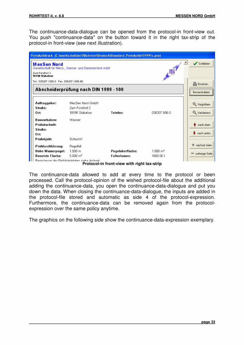
The continuance-data-dialogue can be opened from the protocol-in front-view out.You push "continuance-data" on the button toward it in the right tax-strip of theprotocol-in front-view (see next illustration).
Protocol-in front-view with right tax-strip
The continuance-data allowed to add at every time to the protocol or beenprocessed. Call the protocol-opinion of the wished protocol-file about the additionaladding the continuance-data, you open the continuance-data-dialogue and put youdown the data. When closing the continuance-data-dialogue, the inputs are added inthe protocol-file stored and automatic as side 4 of the protocol-expression.Furthermore, the continuance-data can be removed again from the protocol-expression over the same policy anytime.
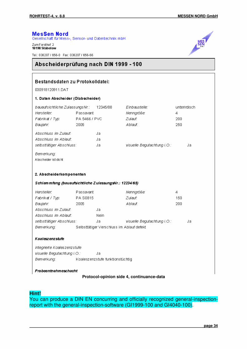
The graphics on the following side show the continuance-data-expression exemplary.
ROHRTEST-4, v. 8.8 MESSEN NORD GmbH
page 34
Protocol-opinion side 4, continuance-data
Hint!You can produce a DIN EN concurring and officially recognized general-inspection-report with the general-inspection-software (GI1999-100 and GI4040-100).

ROHRTEST-4, v. 8.8 MESSEN NORD GmbH
page 35
6.3. Test parameters for tests acc. to DIN EN 805
Measuring-equipment: HIGH PRESSURE
Materials: all specified
Cross-sections: Circle-form
Allowable pressure-losses:automatic calculation after norm-handicaps,Test procedures are described in the standard
materials test procedures test time
Share 2 duktiles Pressure-waste-test 3-24 hCasting-iron
Share 3 casting / steel Accelerated 1..2 hwith cement - normal-proceduresmortar-lining
Communicate 4 steel-tubes / Pressure-waste-testwithout bitumen- 3...24 hlining
Share 5 steel - and Water-loss- 24 h pre-exam.not prestressed concrete- measurement 12...18 hif pressure-tubes realize
Share 6 asbestos-cement Water-loss- 24 hnot measurement 3 ... 24 hrealized
Share 7 PE-HD / PE-LD Contract-ion- 1,5 hPE-X proceed
PVC-U Pressure-loss- 15...18 h proceed

ROHRTEST-4, v. 8.8 MESSEN NORD GmbH
page 36
6.4. Test parameters for tests with compressed air acc. to EN 1610
Measuring-equipment: "COMPRESSED AIR"as well as. "COMPRESSED AIR / VACUUM"
Tube-materials: - Concrete drily- Concrete moist and all other materials
Test sections: 1 to 3 sections of deceased material / cross-section
Tube-lengths: 1..200 m per section
Tube-diameters: 100..1000 mm
The standard gives no hints at the allowable pressure-garbages with coupling ofpipeline-sections of different cross-section / material.The software ROHRTEST realizes a physically correct calculation of the allowabletotal-pressure-waste for up to 3 connected management-sections.
Test pressure: 10 mbar / 50 mbar / 100 mbar / 200 mbar
Allowable pressure-losses:automatic calculation acc. to EN 1610
6.5. Test parameters for special-tests
For each Test procedures (air, water, vacuum, high pressure), a special-test exists.There can be chosen freely all relevant test parameters in the framework of thetechnical possibilities.

ROHRTEST-4, v. 8.8 MESSEN NORD GmbH
page 37
6.6. Test parameters for junction tests
Junction tests are used for the proof of the density of tube-connections (muffs), incontrast to the test of the entire attitude. The filling and test times are very low on thatoccasion on the basis of the low test volumes. In the parameter-dialogue for junctiontests, following inputs can be transacted:
- Client-data (company, place, street, telephone)- Order-data- from shaft / after shaft (course of the stand-section)- Sleeve-number
o current number (it is determined automatically)o free number (sleeve-number must be put down itself)o Reference (reference-test for all sleeve-tests of the test object)
Parameter-dialogue for junction test
On the file "test-type" can be selected test standard, object type and the testparameters.

ROHRTEST-4, v. 8.8 MESSEN NORD GmbH
page 38
Parameter-dialogue for junction test (file test-type)
Junction test fasteners management
You can deposit the data of the existing Junction test fasteners in a table. From thedeposited Junction test fasteners, you can select this currently used or the freeparameter-input in the dialog from a list. The finally used Junction test fasteners isstored.
Over the menu-point configuration / Junction test fasteners... open the Junction testfasteners management (see following illustration).

ROHRTEST-4, v. 8.8 MESSEN NORD GmbH
page 39
Parameter-dialogue for the Junction test fasteners management

ROHRTEST-4, v. 8.8 MESSEN NORD GmbH
page 40
7. Test-transaction
7.1. Tests with measuring-equipment WATER
7.1.1. Preparatory works
It becomes implied that already locked up the pipeline-section to be tested and airsas well as fills for the stipulated duration (pre-filling-time) with water was held.
As in the corresponding norms executed, the pipeline is to be anchored expediently.
− Connect control unit to power supply and to measuring equipment WATER− Connect Water-supply and test object to measuring equipment− Pick "W" for water pressure-tests from the menu-strip of the test software and
input the client and order-object-data in the first appearing file-card.− Choose the Test standard and the Test procedure− Input the object dimensions on the third file-card.
Control unitRT4-ST04
Measuring equipmentWATER

ROHRTEST-4, v. 8.8 MESSEN NORD GmbH
page 41
7.1.2. Test with measuring-equipment WATER − Over the start-button, you reach the test window.− In the diagram, the test pressure is recorded during the pre-filling-phase. This on
the right screen-half gives percent-ad the current loss positionierte, covered on theloss allowed for a positive test-result exactly in% at (relative loss).
− At beginning of the pre-filling, the pressure amounts about in the pipeline. 0 bar,the pump works. The ventilation-cock is for about.
− The end of the pre-filling-process is marked through it that a, the Test pressure the debit-value reached b, itself the relative loss no more serious alters. If with conditions are complied both, the tube is completely filled and thenecessary test pressure prevails in the entire tube. If the test pressure is not reached over a longer time period, is to be tested,whether:− the entrance-page water supply is secured− the lighting hight not 1 m exceeds− the filters a free flow allow− Hoses of enough cross-section are used Big leakages in the pipeline to be tested can make that the necessary Testpressure cannot be reached also with continuous water-addition. To the proof ofthe negative Test results, the test like subsequently is described to start. If the start is not meaningfully for before named reasons, so the Test procedurecan be left.
− If the pre-filling-phase is finished, so the actual measuring-process can beavtivated with START. The status-window in the low part of the screen gives information over it whetherthe measurement immediately begins, or whether the program determines a toobig difference between debit pressure and actual pressure in the tube andtherefore delays the measuring-beginning until the achievement of the debit-pressure.
− If the test began, so the Test pressure and the loss are recorded in the diagram,which later is also component of the protocol. At most allowable and actual water-loss as well as test-time and Test pressure areshown. A premature demolition of the test is with STOP possible, a protocol isproduced in this case only with not-existence of the test.
− If the test-time ran out, so this is signalled acoustically. An input-mask, which makes the adding a remark about the protocol possible, appears afterwards, the produced test report is shown on the screen.

ROHRTEST-4, v. 8.8 MESSEN NORD GmbH
page 42
7.2. Tests with measuring-equipment HIGH PRESSURE (DIN EN 805) 7.2.1. Preparatory works It becomes implied that already cut off the pipeline-section to be tested, with waterfilled and was aired. Since the high pressure-test one-closes a checkup on air-freedom in general, is to bededicated special attention to this criterion in order to avoid verifications.
As in the test standard executed, the pipeline is to be anchored expediently.
− Connect the control unit to the power supply and to mesuring equipment− By the menu-point "H" from the menu-strip, the high pressure-test is selected.− Test parameters in accordance with the input-masks write down, after
confirmation, the test windows appears
Control unitRT4-ST04
Measuring equipmentHIGH RESSURE

ROHRTEST-4, v. 8.8 MESSEN NORD GmbH
page 43
7.2.2. Test-transaction with measuring-equipment HIGH PRESSURE
Under continuous aware control of the software-pressure-ads and the pressuregauge of the measuring-equipment, the Test pressure is found on the pipeline withhelp of the external pump.Follow the instructions of the software on that occasion.
Usually test pressure is reached fast, then however immediately collapses again on alower value.Therefore fill slowly or in several short pushes, until the pressure remainsapproximately constant in the tube-performance also after end of padding.
After achievement of the Test pressurees, the denseness-test starts fullyautomatically.High pressure-denseness-tests under-are divided into the phases in general:
- Pressure-construction- Preaudit- Test and air-freedom- Main-test
One of the part-tests is not passed that so the test procedure with negative resultfinishes.
After completion of the test, the test result is formed automatically and can be printedthe test report.

ROHRTEST-4, v. 8.8 MESSEN NORD GmbH
page 44
7.3. Tests with measuring-equipment AIR acc. to EN 1610
7.3.1. Preparatory works
It becomes implied that the pipeline-section to be tested already was locked up.
RESPECT!
The test with compressed air rescues with improper handling of the test devicessecurity-risks for the user. A damage of the test objects is the further one possiblewith an infringement of the stipulated Test pressurees. We refer 1610 to the pertinentwork-protection-rules and the Test standards DIN EN, LfW 4.3-6 as well as. ÖNORMB 2503.
For the professional handling of the appliance-technology as well as the observanceof the current rules, the user is responsible, the manufacturer of the Test devicestakes over no liability.
!!! All fasteners / hoses / connector are on sure seat to checks and to anchor orto support.
!!! While the pre-filling and the test procedure (as long as the pipeline underPressure stands), present people have to choose her/its/their residence so,that they are can not hurt by for example away-skidded fasteners.
Following works are to be executed to the preparation of the test:
− Connect the control unit to power supply− Connect compressed air-plugs with the labeling "compressor" with a compressed
air-source with a pressure of Max. 2,0 bar connect. See section 3.3. Measuring-equipment AIR / compressed air-supply.
− Pick "L" for air-test from the menu-strip of the test software and input the client andorder-object-data in the first appearing file-card.
− Choose the test standard, the Test procedures on the second file-card the Testpressure
− Input the object dimensions on the third file-card.

ROHRTEST-4, v. 8.8 MESSEN NORD GmbH
page 45
7.3.2. Transaction of the test with compressed air
Change over the start-button to the test-screen. It becomes a diagram and shownon the right side of the currently measured Test pressure, you are in the phase ofthe pressure-construction.
− In the diagram, the Test pressure is recorded during the pre-filling-phase. This onthe right screen-half gives percent-ad the current loss positionierte, covered on theloss allowed for a positive test-result exactly in% at (relative loss).
− At beginning of the pre-filling, the pressure amounts about in the pipeline. 0 bar,the magnet-valve is opened.
− The end of the pre-filling-process is marked through it that a, the Test pressure the debit-value reached b, itself the relative loss no more serious alters. If with conditions are complied both, the tube is completely filled and thenecessary Test pressure prevails in the entire tube. If the Test pressure is not reached over a longer time period, is to be testedwhether:− the compressor right was connected and works− The air-loss / time of the performance of the used compressor corresponds Big leakages in the pipeline to be tested can make that the necessary Testpressure cannot be reached also at continuous compressor-business. To the proofof the negative Test results, the test like subsequently is described to start. If the start is not meaningfully for before named reasons, so the Test procedurewith CLASPS can be left.
− If the pre-filling-phase is finished, so the actual test can be introduced with START. The status-window in the low part of the screen gives information over it whetherthe measurement immediately begins, or whether the program determines a toobig difference between debit pressure and actual pressure in the tube andtherefore delays the measuring-beginning until the achievement of the debit-pressure.
− If the measurement began, so the Test pressure is recorded in the diagram, whichlater is also component of the protocol. At most allowable and actual pressure-loss as well as test-time and Test pressureare shown. A premature demolition of the test is with STOP possible, a protocol isonly produced when the test already "failed" unequivocally.
− If the test-time ran out, so this is signalled acoustically. With CLASPS, the windowis closed. An input-mask, which makes the adding a remark about the protocolpossible, appears afterwards, the produced protocol is shown on the screen.

ROHRTEST-4, v. 8.8 MESSEN NORD GmbH
page 46
7.3.3. Test of tube-connections / junction-test The test of individual tube-connections, in the next junction-proof named, is possiblein different appliance-constellations with the Test system ROHRTEST. Following appliance-constellations are supported for the junction-proof: a, test with standard pipe fasteners: Closing off of the testvolume
Pipe fasteners
Pressure-sensor In the control unit ST04 Filling control offasteners
Manually, connection z.B. over twin-hose-reel RT-MUPZ
Filling control of Testvolume
Automatically over control unit ST04
Remarks Disadvantage: big test volume, hose is "with-tested" b, test with special junction test device Closing off of the testvolume
Particular junction test device
Pressure-sensor In the control unit ST04 Filling control offasteners
Manually, connection z.B. over twin-hose-reel RT-MUPZ
Filling control of Testvolume
Automatically over control unit ST04
Remarks Disadvantage: Hose is "with-tested" c, test with control at the special junction test device Closing off of the testvolume
Particular Muffenprüfgerät
Pressure-sensor Directly at the Muffenprüfgerät Filling control offasteners
Manually, connection with RT-MUPT
Filling control of Testvolume
Automatically directly at the junction test device
Remarks Minimized test volume, shortest test time With application of the variations, b (and c) results in the problem that itself the testvolume reduces directly after the filling. This especially then leads, if is done in theupper nominal-wideness-utilization-area of the junction test devices, therefore e.g.with the RT-PP400 with a nominal-diameter of 500, to an increase of the Testpressurees directly after the filling. This pressure-increase is in this case to benecessarily waited, before is begun with the pressure-waste-test.

ROHRTEST-4, v. 8.8 MESSEN NORD GmbH
page 47
The following stabilization-times are recommended: Nominal-wideness Packer-size Filling-pressure Stabilization-time
DN 200 200 4 bar 1 minDN 250 200 4 bar 3 minDN 300 300 4 bar 1 minDN 400 400 4 bar 2 minDN 500 400 4 bar 6 minDN 500 600 4 bar 1 minDN 700 600 4 bar 8 min

ROHRTEST-4, v. 8.8 MESSEN NORD GmbH
page 48
7.4. Tests with the measuring-equipment SHAFT
7.4.1. Preparatory works
It becomes implied that already drained the receptacle to be tested, cleaned, lockedup and with clear water was replenished.
RESPECT! The measuring-equipment SHAFT is water admitted exclusively forthe test with the test medium water. It doesn't possess any admission for theex-area, it’s not specified for explosive liquids or gases.
According to material and condition of the object material, a repletion-phase must beput in front the test.
The device is set up over the opening of the receptacle to be tested with the tripodand the level-probe, extends harnessed with the required tube-extensions in thetripod. The sensor-main lead is connected with tuner-amplifier and level-probe and isswitched on the control unit.
Drove with automatic water-addition over measuring-equipment WATER: In this caseover the dispatcher-box, level-sensor and measuring-equipment WATER areconnected (see point 1.3, B) with the control unit simultaneously.
The test software is started, and the water-test (W) chosen. After the order-data wereinput, becomes on file-card 2 as test object shaft / chosen separators with or withoutconnected pipeline.
The input of the object parameters takes place in accordance with section 6.2.2.

ROHRTEST-4, v. 8.8 MESSEN NORD GmbH
page 49
7.4.2. Transaction of the test with the measuring-equipment SHAFT
After conclusion of the data input, the actual test-screen is started. Doesn't yet startthe actual test but the screen-ad at first putting in of the beginning-water-stand aswell as the control of the attitudes allow.
This water-levels should be at beginning of the test between the two rings of thelevel-sensor, what through variation of the water-stand or through beginning / sinkingof the level-probe can be reached.
RESPECT! Avoid out the sinking the sensor over the upper ring! A exposition of thesensor-lensis can lead to measuring-mistakes at a subsequent test!
In the status-window of the test window, hints are given to the attitude of the testlevel, in principle it should at beginning of the test of the upper third of the measuring-area of 50 mm lies.
After conclusion of the water-level-attitude, the actual test is started by clicking thestart-button. Going out, the level-change becomes from the so-called zero-water-stand captured to the post-time-point as well as. the water-loss over the test timeclung.
With application of the automatic water addition with the measuring-equipmentWATER, the behavior directs "automatic water-addition toward him/it at test-end" foritself after the attitude of the counter in the section 7.4.1. represented parameter-windows.If this counter is active, so the water-addition takes place on the test-end (d.h). thezero-water-stand is restored, he/it is inactive, so the level is held virtually steadilythrough continuous water-additions. So, also tests with allowable level-loss can becarried out over 50mm.
With application of the automatic water addition without the measuring-equipmentWATER, the test is not stopped after the actual test time. The record is continuedexplicitly until the user on the button "STOP" presses. During this additionalmeasuring-phase, the water-addition can take place manually. After the pressing theStop-button over an input-window, the user must declare the manually added water-quantity.
The value of the water-addition appears at activation in both cases in the test-protocol.

ROHRTEST-4, v. 8.8 MESSEN NORD GmbH
page 50
8. Data-concept
8.1. Storage of the Test reports
The following scheme shows the flow of information, which emerges at thepreparation of a test report.
Test procedure (Standard, Test time, Test pressure, allowable losses...)
Order-parametersr (Clients, adapters ROHRTEST- Use-place, test section...) Report
Management-parametersr (Cross-section, length, material Diameters, sensor-height...)
Tube-test-transactiong (Graphic, measurements)
All test-parameters for a taken place test are set aside (instead of C:\RT, analternative installation-table can be declared during the Setup) on the hard disk of thePC under automatically forgiven protocol-numbers in the standard-data-tableC:\RT\DATEN. The data-path can be picked configuration / program-parameter freelyover the menu after the installation.
The protocol-numbers (file-names) become after the scheme JJMMTTHHMMSS.DATfrom the date and the time formed. The protocol-file 020306141530.DAT gets alongz.B. for an test at the 06.03.2002 14:15 o'clock and 30 seconds.
The data-table is generated automatically in following manner:
C:\RT\DATEN\ [clients 1] [construction-intents 1] [protocol 1]oll 1]
[Clients 2] [construction-intents 2] [protocol 2] 2]
... ... ...
Over the knowledge of the protocol-number as well as. for the client and project, it ispossible to find the data of an already cast off test and to load again, to represent theprotocol and to print out.

ROHRTEST-4, v. 8.8 MESSEN NORD GmbH
page 51
8.2. Project-administration
All clients as well as all construction-intents and test objects are graspedautomatically in an internal data base of the test software and stand in the case ofthe re-application without retyping of the data about the disposal so.
8.2.1. Transferred by data-continuances, updating of the project-administration
Changes are carried out at the data-continuance, like this z.B. with the erasure orpostponing of protocol-files over the Windows-Explorer or but when adding Testreportsn (z.B). when transferring of Test parameter on the office-calculator, happens,so data base and test protocol pool agree no more.In this case, the menu-point should reorganize" "project-administration beenexecuted "data" in the menu. It is scanned the entire data-continuance on thatoccasion automatically in the data-table of the Test software, and the data baseupdates.
8.2.2. Summary from Test reports to lists and overview-tables
Over the menu-point "project-administration" of the menu "data" as well as. thecorresponding symbol in the menu-strip can be called the project-administration.
(Project-administration)

ROHRTEST-4, v. 8.8 MESSEN NORD GmbH
page 52
The project-administration makes it possible, as well as to find Test reports againcomfortably and to open, to produce also as lists and overview-tables of the testsafter different order-criterions.
With a double-click on a line of the project-administration, the protocol-opinion of therespective protocol is called. With the right mouse-button on a line clicked, a menuopens. Can show the pressure-preview so, a protocol-list-opinion generates or theTest parameter of the protocol are taken over for a new test.
Over the button "search-mask / filter-options" can be searched the data base freelyafter certain criterions like Prüfnorm, test result, client-name, place, Test proceduresand many further ones. In the project-administration, the results of the search areonly shown then. A click on the button "universe records shows" shows the completecontent of the data base again.
Which columns should be shown in the project-administration, can configure beenestablished over "data-opinion."
The user can choose the sequence of the columns freely, in that positioniert he/it thecolumns through traction of the column-head. The column-width can be set freely.The layout of the user-defined opinion is stored by the software automatically.Consequently, one is seized optimally on the user of cut data-opinion.
A click on the column-title sorts the data-opinion after this column. The decisivecolumn-title is deposited dark-gray.
Over the buttons "protocol-list construction-intents" and "protocol-list Test object" canbe generated overview-lists of the protocols about a project. It had to be markedhowever exactly one line of the project-administration previously. The lists cancontain only the before filtered data or all protocols of the project. A correspondingretrieval leaves this decision to the user. Before the representing the protocol-list, theuser can establish up to 4 Sortierkriterien simultaneously. So, the protocols can z.B.first after Prüfnorm, then after test result and is sorted simultaneously after Prüfzeit.Furthermore, the Sortierrichtung (rising or descends) can be established for everycriterion. So, a maximum at flexibility is guaranteed.
Especially for users, which execute stand and sleeve-tests, this type of the reportsessential advantages produces. Complete test reports overviews, in which the mostimportant test parameters sorted tabulated, can be generated been listed.
Beside the printing out the lists, it also is possible to let printed out all singles-protocols of a chosen overview-level.

ROHRTEST-4, v. 8.8 MESSEN NORD GmbH
page 53
Order-criterion Uses
Construction-intents
Ad and expression of all Test objects of a Procet in both list-formand as singles-protocols, therefore z.B. the overview over a wholebuilding site or property
Test object Ad and expression of all Test reports of a Test objectss in both list-form and as singles-protocols, therefore z.B. all junction testreports of an attitude or the protocols of the tests before / after aredevelopment
The following example shows an excerpt from such a list-representation for a chosenTest object.
Protocol-list for sleeve-tests side 1

ROHRTEST-4, v. 8.8 MESSEN NORD GmbH
page 54
8.3. Preparation and alteration of Test report forms
The preparation of the Test reports takes place through the Test software underapplication of protocol-presentations. On this occasion, it is about text files, whichdescribe the format and the content of the Test reports. Protocol-presentations existfor all Test standards and Test procedures.
8.3.1. Saving system of the Test report forms
The Test report forms are stored like follows:
Standard-version "C:\RT"Table Description of the existing dataC:\RT\ - Program-files (EX and INI-files)
- Data bases (client and project-data base)
C:\RT\Deutsch\ - individually shaped protocol-presentations (*.PER - files,if existing
C:\RT\Deutsch\Standard_Protokolle
- Standard-protocol-presentations (*.PER - files
C:\RT\Deutsch\GPS_Protokolle
- Standard-protocol-presentations (*.PER, files, withactivated GPS, option
Tube-test-appliance with several ports and standard-installation-table "C:\RT"Table Description of the existing data
Black program-version (1).port
C:\RT\DBRT41 - Program-files (EX and INI-files)- Data bases (client and project-data base)
C:\RT\DBRT41\Deutsch\ - individually shaped protocol-presentations (*.PER -files, if existing
C:\RT\DBRT41\Deutsch\Standard_Protokolle
- Standard-protocol-presentations (*.PER - files
C:\RT\DBRT41\Deutsch\GPS_Protokolle
- Standard-protocol-presentations (*.PER, files, withactivated GPS, option
Red program-version (2). port
C:\RT\DBRT42 - Program-files (EX and INI-files)- Data bases (client and project-data base)
C:\RT\DBRT42\Deutsch\ - individually shaped protocol-presentations (*.PER -files, if existing
C:\RT\DBRT42\Deutsch\Standard_Protokolle
- Standard-protocol-presentations (*.PER - files
C:\RT\DBRT42\Deutsch\ - Standard-protocol-presentations (*.PER, files, with

ROHRTEST-4, v. 8.8 MESSEN NORD GmbH
page 55
GPS_Protokolle activated GPS, option
Yellow program-version (3). Messport
C:\RT\DBRT43 - Program-files (EX and INI-files)- Data bases (client and project-data base)
C:\RT\DBRT43\Deutsch\ - individually shaped protocol-presentations (*.PER -files, if existing
C:\RT\DBRT43\Deutsch\Standard_Protokolle
- Standard-protocol-presentations (*.PER - files
C:\RT\DBRT43\Deutsch\GPS_Protokolle
- Standard-protocol-presentations (*.PER, files, withactivated GPS, option
Individually changed protocol-presentations must be copied into the correspondingtable. These presentations then are treated preferentially, d.h. as far as an individualprotocol-presentation exists, this is also used.
The following list allows the assignment of the protocol-presentations to the Teststandards and .verfahren, you please order a list of the used data fields with demandwith the manufacturer.
File-name Prüfnorm1.per Denseness-special-test (procedures air)1m.per Sleeve-special-test (procedures air)12562s.per Denseness-test of DIN EN 12566 – 11391.per Denseness-test of ATV/DWA 139 (procedures air)1391m.per Sleeve-test of ATV/DWA 139 (procedures air)1392.per Denseness-test of ATV/DWA 139 (procedures water)1392f.per Denseness-test of ATV/DWA 139 (W)1392s.per Shaft-denseness-test of ATV/DWA 139 (W)1393.per Denseness-test of ATV/DWA 139 (procedures hypotension)142.per Denseness-test of ATV/DWA A 142 (procedures hypotension)1431.per Denseness-test of ATV/DWA M 143-6 (procedures air)1431m.per Sleeve-test of ATV/DWA M 143-6 (procedures air)1432.per Denseness-test of ATV/DWA M 143-6 (procedures water)1432f.per Denseness-test of ATV/DWA M 143-6 (W)1432s.per Shaft-denseness-test of ATV/DWA M 143-6 (W)1433.per Denseness-test of ATV/DWA M 143-6 (procedures hypotension)1433m.per Sleeve-denseness-test of ATV/DWA M 143-6 (procedures
hypotension)16111.per Denseness-test of DIN EN 1610 (procedures air)16111m.per Sleeve-test of DIN EN 1610 (procedures air)16112.per Denseness-test of DIN EN 1610 (procedures water)16112f.per Denseness-test of DIN EN 1610 (W)16112s.per Shaft-denseness-test of DIN EN 1610 (W)19991f.per Denseness-test of DIN 1999 – 10019991s.per Separator-test of DIN 1999 – 1001999f.per Denseness-test of DIN 1999

ROHRTEST-4, v. 8.8 MESSEN NORD GmbH
page 56
1999s.per Separator-test of DIN 19992.per Denseness-special-test (procedures water)File-name Prüfnorm2f.per Denseness-special-test (procedures water)2s.per Shaft-denseness-special-test (W)25031.per Denseness-test of ÖNorm B 2503 (procedures air)25031m.per Sleeve-test of ÖNorm B 2503 (procedures air)25032.per Denseness-test of ÖNorm B 2503 (procedures water)3.per Denseness-special-test (procedures high pressure)4.per Denseness-special-test (procedures vacuum)4033.per Denseness-test of DIN 4033 (procedures water)40401f.per Denseness-test of DIN 4040 – 10040401s.per Separator-test of DIN 4040 – 1004261s.per Denseness-test of DIN 4261 – 1438.per Denseness-test of LfW 4.3-6 1992 (procedures air)438m.per Sleeve-test of LfW 4.3-6 1992 (procedures air)4381.per Denseness-test of LfW 4.3-6 1999 (procedures air)4381m.per Sleeve-test of LfW 4.3-6 1999 (procedures air)4382.per Denseness-test of LfW 4.3-6 1999 (procedures water)4382f.per Denseness-test of LfW 4.3-6 1999 (W)4382s.per Shaft-denseness-test of LfW 4.3-6 1999 (W)4383.per Denseness-test of LfW 4.3-6 (procedures hypotension)792.per Inner-pressure-test of DIN 4279 part 1 and DIN 4279 part 2793.per Inner-pressure-test of DIN 4279 part 1 and DIN 4279 part 3794.per Inner-pressure-test of DIN 4279 part 1 and DIN 4279 part 4797.per Inner-pressure-test of DIN 4279 part 1 and DIN 4279 part 78053.per Inner-pressure-test of EN 805
Table 1: Overview over the protocol-files and her/its/their appropriate measuring-rule
Through the new storage-concept, a maximum at flexibility becomes possible.Individual protocol-presentations are not entitled with new installation, and theapplication nevertheless uses the most current protocol-presentations with entire newfunctionality.

ROHRTEST-4, v. 8.8 MESSEN NORD GmbH
page 57
8.4. Test parameter getting from Test reports
Since the program-version 8.6, the Test parameter can be loaded already by carriedout measurements, about the corresponding configuration from the last test of thisobject, to read. Client-data, Test objectdaten, parameters and object-parameters firstare adopted on that occasion and can, with demand, is edited afterwards. Thecorresponding protocol-file can load "Test parameter of protocol-file over the menu-point". in the menu "data" is selected.
Menu "data" in the main-application-window
Alternatively, loading can take place (see following illustration) over thecorresponding ToolButton in the control-strip.
Toolbar of the tube-test-software
From the version 8.7, the Test parameter can also be taken over from a protocolselected in the project-administration for a new test. The corresponding line with theright mouse-button must be clicked on to it and the entry adopts" "protocol-data in thecontext-menu for a new test is selected.
Context-menu in the project-administration

ROHRTEST-4, v. 8.8 MESSEN NORD GmbH
page 58
8.5. Configuration of the option "GPS"
With a connected GPS-Sensor, the current GPS-Position is entered automaticallyinto the test report. The required driver (with USB - appliances) of the sensor isincluded by the manufacturer and must be installed after manufacturer-handicaps.
The sensor must the NMEA, protocol supports, so that they tube-test, software thecurrent position can finish reading. The interface-parameters please infer you fromthe documentation of the GPS-Sensors would use by you. All required attitudes canbe given a talking to "GPS-Sensor-Daten" in the dialogue-window. The dialogue-window can "GPS-Sensorcheck" over the menu-point. in the menu "configuration" iscalled.
Please heed that the sensor after switching on requires a certain time to thedetermining the current position. You/they can observe the sensor-status directly inthe configuration-dialogue. The UTC-time, the GPS-position as well as status-newsare shown with it.
GPS-Sensor configuration-dialogue with current position and time-ad
The retrieval of the GPS-data can starts / stops" started over the button of "GPS-Sensorrequest and is broken. In order to get a valid GPS-Position in the protocol, theretrieval must have started. The start of the test is tried to determine a valid GPS-Position. If this doesn't succeed, the user is asked, whether he/it would like to repeatthe attempt, otherwise the test is started, and the entry takes place "no GPS-Positionavailable" in the protocol.

ROHRTEST-4, v. 8.8 MESSEN NORD GmbH
page 59
9. Maintenance and function-test
9.1. Appliance-check
If doubts of the correct function of the test device exist the software supports you withthe mistake-orientation. With the menu-point of "appliance-checking" in the menu"configuration" is called a routine, which determines the internal appliance-parameters and shows on the screen.
Lists or please prints you the there spent information before you establish contactwith our service.
9.2. Cleaning of the filter of the measuring-equipment WATER
* Take away the 4 outer srews which fortify the front-plate at the suitcase* Take the front-plate with the entire measuring-construction from the suitcase
out* Take away the 4 srews as well as the valve-levers, the front-plate can be
removed after it* This water-filters is beside the pressure gauge left. Solve them/her/it
Filter-fortification.* Solve the hose-bell at the end directed to the hand-valve of this Filter, you
remove the hose.* The filter-nozzle lets itself now unscrew. Take the filter-use and clean this with
a brush. If you possibly rinse them/her/it Filter-nozzle from.* The montage of the measuring-equipment takes place in reverse sequence

ROHRTEST-4, v. 8.8 MESSEN NORD GmbH
page 60
9.3 Changeover to winter-business (all measuring-facilities)
The ROHRTEST-devives are for the business with air-temperatures below 0, Cdoesn't specify. In order to prevent a damage of the Prüftechnik with camp-temperatures below 0, following points are to be heeded:
* Measuring-facilities WATER and HIGH PRESSURE empty and withFrost-protection (z.B). Motor vehicle-cooler-frost-protection, in accordance withthe required camp-temperature replenishes
* Condensations from the measuring-equipment AIR take away* LCD-screebs (Notebook) never with temperatures below - 15, C camp
9.4. Test of the appliance-function, own-control
The manufacturer recommends, the test device also within the calibration intervalls(z.B). weekly, to subject a control on proper function.
Test the appliance-denseness ST04, measuring-equipment AIR / VACUUM
For the pressure test devices, this test involves the general measuring-function z.B.with a comparison-measuring instrument as well as the test of denseness of the Testsystems.A sample turns into the control of the denseness of the Test devices at a guaranteesto dense test-construction executed. A pipeline DN proved itself 100 to it with alength of 1 m, which locked densely on both sides and is interconnected with thePrüfgerät. With a Test pressure of 200 mbar, the pressure-loss can amount to atmost 1 mbar in 3 min.
9.5. Cleaning of the measuring-equipment SHAFT
Since the level-sensor of the measuring-equipment SHAFT has direct contact withthe Prüfmedium water, he/it is regular on impurities to tests, ggf. these are to betaken away. All statements refer upright to him/it, with the screw thread-connectionupward standing level-sensor. The cleaning takes place only with a mild household-clearer (z.B) in principle. Washing liquids.
a) Cleaning of the strainer-element: The 3 screws of the lowermost screw-ringare to be taken away, the strainer is ggf. with a brush, to clean.
b) Cleaning of the swimmer: The 3 screws of the middle screw-ring are to betaken away, the interior as well as the swimmer are to be cleaned
c) Cleaning of the sensor-head: The 3 screws of the upper screw-ring are to betaken away, the lentil of the sensor-head is to be cleaned carefully and to dryafterwards.

ROHRTEST-4, v. 8.8 MESSEN NORD GmbH
page 61
Changes of the sense of a technical development keeps itself the manufacturer before.
Heed please corresponding documentation-supplements.
With hints and questions, you please turn to them/her/it
MesSen Nord GmbH Zum Forsthof 2
D-18198 Stäbelow
Tel: +49 38207 / 656 - 0 FAX: +49 38207 / 656 - 66

Denseness-tests of DIN EN 1610 conditions Octobers 1997
Air: (Procedures "L")Material Procedur
esp0(mbar)
(p(mbar))
Prüfzeit in min
DN 100 DN 200 DN 300 DN 400 DN 600 DN 800 DN 1000Concrete drily LA 10 2,5 5 5 5 7 11 14 18
LB 50 10 4 4 4 6 8 11 14LC 100 15 3 3 3 4 6 8 10LD 200 15 1,5 1,5 1,5 2 3 4 5
Concrete moist and all LA 10 2,5 5 5 7 10 14 19 24LB 50 10 4 4 6 7 11 15 19
other materials LC 100 15 3 3 4 5 8 11 14LD 200 15 1,5 1,5 2 2,5 4 5 7
Measuring-precision pressure-waste 10 percent (p) Pacification-time about. 5 min Pressure-waste is to berecorded!
Water: (Procedures "W") p0 = 0,1... 0,5 barPre-filling-time : 1 Hour until 24 hours (concrete), if necessary Pressure-waste and water-addition are to be
recorded!Duration : 30 minPressure-precision :
10 mbar
Water-loss: 0,15 l/m2 in 30 min for tubes (inner surface)0,2 l / m² in 30 min for pipelines einschl. Shafts0,4 l/m2 in 30 min for shafts at singles-test
MesSen Nord GmbH www.messen-nord.de

Denseness-tests of the leaflet of the estate 1.7.1999Bavarian regional-office of water-economyLfW 4.3-6Air: (Procedures "L")Material Procedur
esp0(mbar)
(p(mbar))
Prüfzeit in min
DN 100 DN 200 DN 300 DN 400 DN 600 DN 800 DN 1000All materials LC* 100 15 2,5 4,5 7 9 14 18 23
LD* 200 15 1,5 3 5 6 10 13 16Measuring-precision pressure-waste 10 percent (p) Pacification-time DN / 100 in min Pressure-waste is to be recorded!
Hypotension-testMaterial Procedur
esp0(mbar)
(p(mbar))
Prüfzeit in min
DN 100 DN 200 DN 300 DN 400 DN 600 DN 800 DN 1000All materials -100 11 2,5 4,5 7 9 14 18 23
-200 11 1,5 3 5 6 10 13 16Measuring-precision pressure-waste 10 percent (p) Pressure-waste is to be recorded!
Water: (Procedures "W") p0 = 0,1... 0,5 bar, hydro-did. Print through shaft-filling until waiter-edgePre-filling-time : 1 Hour until 24 hours (concrete), if necessary Pressure-course and water-addition are to be
recorded!Duration : 30 minPressure-precision :
10 mbar
Water-loss: 0,15 l/m2 in 30 min for tubes (inner surface)0,2 l / m² in 30 min for pipelines einschl. Shafts0,4 l/m2 in 30 min for shafts at singles-test
MesSen Nord GmbH www.messen-nord.de


Denseness-tests of leaflet ATV/DWA M 143, part 6 stand 1996Test of existing sewage-systems
Air-overpressure-testMaterial Test
pressure p0(mbar)
(p(mbar))
Prüfzeit in min
DN100
DN200
DN300
DN400
DN500
DN600
DN700
DN 800 DN 900 DN 1000
All materials 100 15 1 2 3 4 5 6 7 8 9 10Measuring-precision pressure-waste 10 percent(p)
Pacification-time DN / 100 in min Pressure-waste is to be recorded!
Hypotension-testMaterial Test
pressure p0(mbar)
(p(mbar))
Prüfzeit in min
DN100
DN200
DN300
DN400
DN500
DN600
DN700
DN 800 DN 900 DN 1000
All materials -100 12 1 2 3 4 5 6 7 8 9 10Measuring-precision pressure-waste 10 percent(p)
Pacification-time DN / 100 in min Pressure-course is to be recorded!
Water pressure-test p0 = 50 mbar over tube-vertexes of the topmost-situated point, at higher business-water-stand until Max. 500 mbarPre-filling-time : 1 Hour until 24 hours (concrete), if necessary Pressure-course and water-addition are to be recorded!Duration : 15 minPressure-precision:
10 mbar
Water-loss: 0,2 l/m2 in 15 min for tubes (inner surface)
MesSen Nord GmbH www.messen-nord.de

MesSen Nord GmbH www.messen-nord.de
DIN 1999 - 100
Regelfall: Neubau
Auffüllung bis 20mmunter OK Schacht
max. Verlust 500 ml/StundeBehälterbereich
Auffüllung bis 100mmüber OK Rohrscheitel
max. Verlust 500 ml/Stunde
Schachtbereich
Auffüllung bis 20mmunter OK Schacht
max. Verlust 400 ml(je m² und StundePrüfzeit)
benetzte innereOberflächedes Schacht-bereiches
Prüfdauer: t = 2h • Pegeloberfläche • Messgenauigkeit [h] dm³ [m²] [mm]
Mindestprüfdauer: 0,5h bzw. 0,1h • Pegeloberfläche
20mm unterAbdeckung
Einlauf 100mmüber OKRohrscheitel
Behälterbereich
Sonderfall: Altbestand
Schacht-bereich
Prüfung nach besonderen Bedingungen:(nur mit behördlicher Genehmigung undnur für Altbestände)
Wie Regelfall, aber nur Auffüllung desBehälterbereiches

MesSen Nord GmbH www.messen-nord.de
DIN 4040 - 100
Regelfall: Behälterbereich
Auffüllung bis 100mmüber OK Rohrscheitel
max. Verlust 500 ml/Stunde
Regelabfall: Schachtbereich
Auffüllung bis 20mmunter OK Schacht
max. Verlust 400 ml(je m² und StundePrüfzeit)
benetzte innereOberflächedes Schacht-bereiches
Prüfdauer: t = 2h • Pegeloberfläche • Messgenauigkeit [h] dm³ [m²] [mm]
Mindestprüfdauer: 0,5h bzw. 0,1h • Pegeloberfläche
20mm unterAbdeckung
Einlauf 100mmüber OKRohrscheitel
Behälterbereich
Schacht-bereich
Prüfung nach besonderen Bedingungen:(nur mit behördlicher Genehmigung undnur für Altbestände)
Ausführung wie Regelfall Behälterbereich