tightness controls tc
TRANSCRIPT

Edition 10.20EN
Tightness controls TC
• Adjustable test period which can be adapted to different systems• Adjustable test instant allows quick system start• Maximum safety thanks to self-monitoring electronics
03250636
TECHNICAL INFORMATION
AGA
Safety manual for products complying with EN 61508-2
TC · Edition 10.20 · EN 2
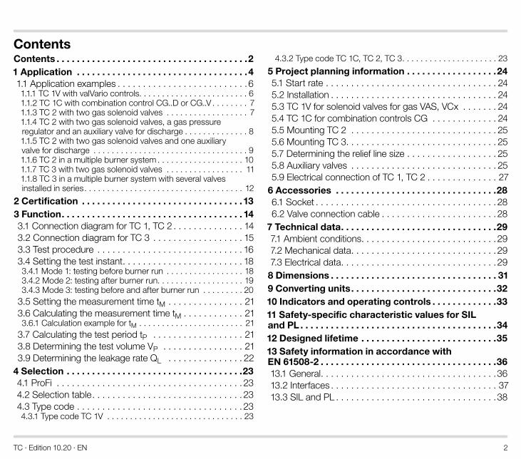
ContentsContents . . . . . . . . . . . . . . . . . . . . . . . . . . . . . . . . . . . . . .21 Application . . . . . . . . . . . . . . . . . . . . . . . . . . . . . . . . . .41.1 Application examples . . . . . . . . . . . . . . . . . . . . . . . . . .61.1.1 TC 1V with valVario controls. . . . . . . . . . . . . . . . . . . . . . . . 61.1.2 TC 1C with combination control CG..D or CG..V . . . . . . . . 71.1.3 TC 2 with two gas solenoid valves . . . . . . . . . . . . . . . . . . 71.1.4 TC 2 with two gas solenoid valves, a gas pressure regulator and an auxiliary valve for discharge . . . . . . . . . . . . . . 81.1.5 TC 2 with two gas solenoid valves and one auxiliary valve for discharge . . . . . . . . . . . . . . . . . . . . . . . . . . . . . . . . . . 91.1.6 TC 2 in a multiple burner system . . . . . . . . . . . . . . . . . . . 101.1.7 TC 3 with two gas solenoid valves . . . . . . . . . . . . . . . . . 111.1.8 TC 3 in a multiple burner system with several valves installed in series. . . . . . . . . . . . . . . . . . . . . . . . . . . . . . . . . . . 12
2 Certification . . . . . . . . . . . . . . . . . . . . . . . . . . . . . . . .133 Function . . . . . . . . . . . . . . . . . . . . . . . . . . . . . . . . . . . . 143.1 Connection diagram for TC 1, TC 2 . . . . . . . . . . . . . . 143.2 Connection diagram for TC 3 . . . . . . . . . . . . . . . . . . 153.3 Test procedure . . . . . . . . . . . . . . . . . . . . . . . . . . . . . 163.4 Setting the test instant. . . . . . . . . . . . . . . . . . . . . . . . 183.4.1 Mode 1: testing before burner run . . . . . . . . . . . . . . . . . 183.4.2 Mode 2: testing after burner run. . . . . . . . . . . . . . . . . . . 193.4.3 Mode 3: testing before and after burner run . . . . . . . . . 20
3.5 Setting the measurement time tM . . . . . . . . . . . . . . . 213.6 Calculating the measurement time tM . . . . . . . . . . . . 213.6.1 Calculation example for tM . . . . . . . . . . . . . . . . . . . . . . . 21
3.7 Calculating the test period tP . . . . . . . . . . . . . . . . . . 213.8 Determining the test volume VP . . . . . . . . . . . . . . . . 213.9 Determining the leakage rate QL . . . . . . . . . . . . . . . 22
4 Selection . . . . . . . . . . . . . . . . . . . . . . . . . . . . . . . . . . .234.1 ProFi . . . . . . . . . . . . . . . . . . . . . . . . . . . . . . . . . . . . .234.2 Selection table. . . . . . . . . . . . . . . . . . . . . . . . . . . . . .234.3 Type code . . . . . . . . . . . . . . . . . . . . . . . . . . . . . . . . .234.3.1 Type code TC 1V . . . . . . . . . . . . . . . . . . . . . . . . . . . . . . 23
4.3.2 Type code TC 1C, TC 2, TC 3. . . . . . . . . . . . . . . . . . . . . 23
5 Project planning information . . . . . . . . . . . . . . . . . .245.1 Start rate . . . . . . . . . . . . . . . . . . . . . . . . . . . . . . . . . . 245.2 Installation . . . . . . . . . . . . . . . . . . . . . . . . . . . . . . . . . 245.3 TC 1V for solenoid valves for gas VAS, VCx . . . . . . . 245.4 TC 1C for combination controls CG . . . . . . . . . . . . . 245.5 Mounting TC 2 . . . . . . . . . . . . . . . . . . . . . . . . . . . . . 255.6 Mounting TC 3. . . . . . . . . . . . . . . . . . . . . . . . . . . . . . 255.7 Determining the relief line size . . . . . . . . . . . . . . . . . . 255.8 Auxiliary valves . . . . . . . . . . . . . . . . . . . . . . . . . . . . . 255.9 Electrical connection of TC 1, TC 2 . . . . . . . . . . . . . . 27
6 Accessories . . . . . . . . . . . . . . . . . . . . . . . . . . . . . . . .286.1 Socket . . . . . . . . . . . . . . . . . . . . . . . . . . . . . . . . . . . . 286.2 Valve connection cable . . . . . . . . . . . . . . . . . . . . . . . 28
7 Technical data . . . . . . . . . . . . . . . . . . . . . . . . . . . . . . .297.1 Ambient conditions. . . . . . . . . . . . . . . . . . . . . . . . . . .297.2 Mechanical data. . . . . . . . . . . . . . . . . . . . . . . . . . . . .297.3 Electrical data. . . . . . . . . . . . . . . . . . . . . . . . . . . . . . .298 Dimensions . . . . . . . . . . . . . . . . . . . . . . . . . . . . . . . . . 319 Converting units . . . . . . . . . . . . . . . . . . . . . . . . . . . . .3210 Indicators and operating controls . . . . . . . . . . . . .3311 Safety-specific characteristic values for SIL and PL . . . . . . . . . . . . . . . . . . . . . . . . . . . . . . . . . . . . . . .3412 Designed lifetime . . . . . . . . . . . . . . . . . . . . . . . . . . .3513 Safety information in accordance with EN 61508-2 . . . . . . . . . . . . . . . . . . . . . . . . . . . . . . . . . . .3613.1 General. . . . . . . . . . . . . . . . . . . . . . . . . . . . . . . . . . .3613.2 Interfaces . . . . . . . . . . . . . . . . . . . . . . . . . . . . . . . . . 3713.3 SIL and PL . . . . . . . . . . . . . . . . . . . . . . . . . . . . . . . .38
TC · Edition 10.20 · EN 3
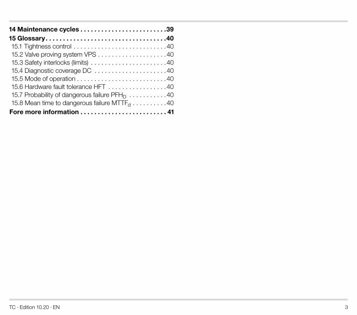
14 Maintenance cycles . . . . . . . . . . . . . . . . . . . . . . . . .3915 Glossary . . . . . . . . . . . . . . . . . . . . . . . . . . . . . . . . . . .4015.1 Tightness control . . . . . . . . . . . . . . . . . . . . . . . . . . .4015.2 Valve proving system VPS . . . . . . . . . . . . . . . . . . . .4015.3 Safety interlocks (limits) . . . . . . . . . . . . . . . . . . . . . .4015.4 Diagnostic coverage DC . . . . . . . . . . . . . . . . . . . . .4015.5 Mode of operation . . . . . . . . . . . . . . . . . . . . . . . . . .4015.6 Hardware fault tolerance HFT . . . . . . . . . . . . . . . . .4015.7 Probability of dangerous failure PFHD . . . . . . . . . . .4015.8 Mean time to dangerous failure MTTFd . . . . . . . . . .40Fore more information . . . . . . . . . . . . . . . . . . . . . . . . . 41
TC · Edition 10.20 · EN 4
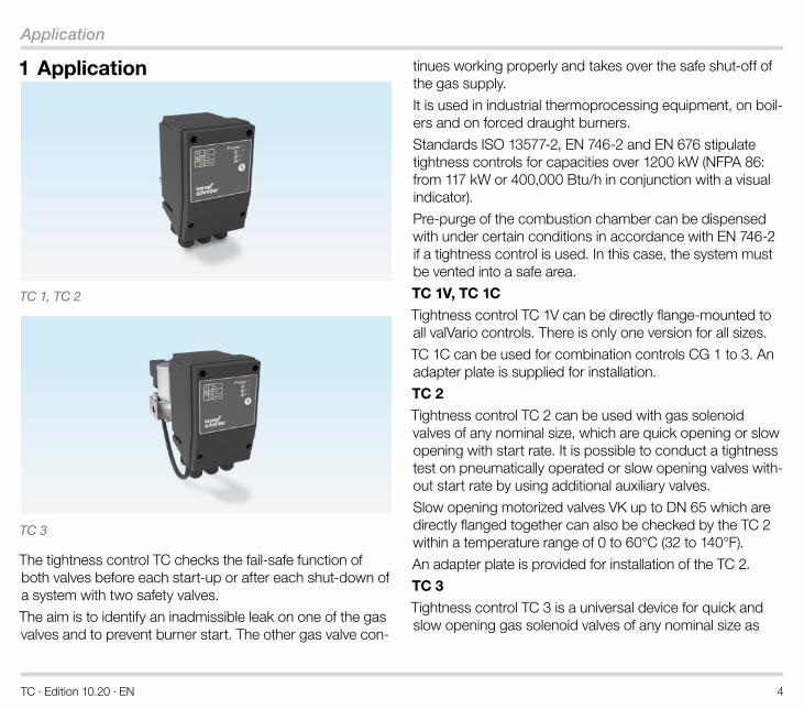
Application
1 Application
TC 1, TC 2
TC 3
The tightness control TC checks the fail-safe function of both valves before each start-up or after each shut-down of a system with two safety valves.
The aim is to identify an inadmissible leak on one of the gas valves and to prevent burner start. The other gas valve con-
tinues working properly and takes over the safe shut-off of the gas supply.
It is used in industrial thermoprocessing equipment, on boil-ers and on forced draught burners.
Standards ISO 13577-2, EN 746-2 and EN 676 stipulate tightness controls for capacities over 1200 kW (NFPA 86: from 117 kW or 400,000 Btu/h in conjunction with a visual indicator).
Pre-purge of the combustion chamber can be dispensed with under certain conditions in accordance with EN 746-2 if a tightness control is used. In this case, the system must be vented into a safe area.
TC 1V, TC 1C
Tightness control TC 1V can be directly flange-mounted to all valVario controls. There is only one version for all sizes.
TC 1C can be used for combination controls CG 1 to 3. An adapter plate is supplied for installation.
TC 2
Tightness control TC 2 can be used with gas solenoid valves of any nominal size, which are quick opening or slow opening with start rate. It is possible to conduct a tightness test on pneumatically operated or slow opening valves with-out start rate by using additional auxiliary valves.
Slow opening motorized valves VK up to DN 65 which are directly flanged together can also be checked by the TC 2 within a temperature range of 0 to 60°C (32 to 140°F).
An adapter plate is provided for installation of the TC 2.
TC 3
Tightness control TC 3 is a universal device for quick and slow opening gas solenoid valves of any nominal size as
TC · Edition 10.20 · EN 5
Application
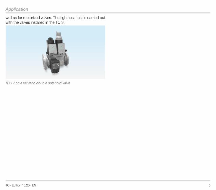
well as for motorized valves. The tightness test is carried out with the valves installed in the TC 3.
TC 1V on a valVario double solenoid valve
TC · Edition 10.20 · EN 6
Application
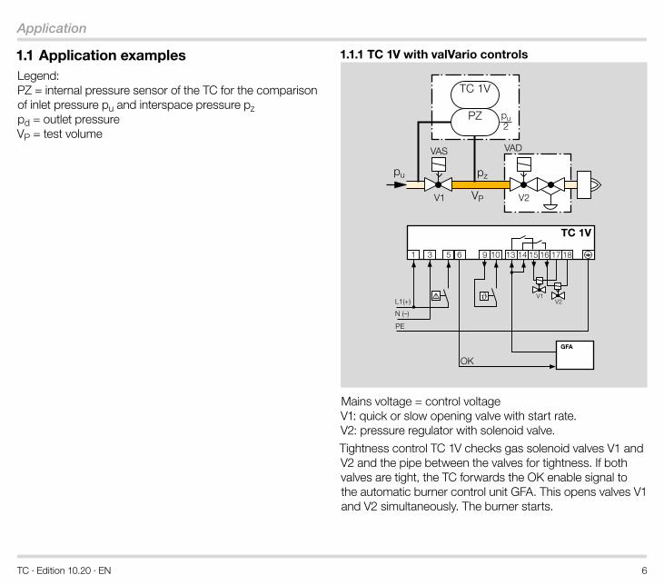
1 .1 Application examplesLegend: PZ = internal pressure sensor of the TC for the comparison of inlet pressure pu and interspace pressure pz pd = outlet pressure VP = test volume
1 .1 .1 TC 1V with valVario controls
V1 V2
VADVAS
PZ
pu pz
VP
TC 1V
pu2
TC 1V
OK
9
V2V1
GFA
Mains voltage = control voltage V1: quick or slow opening valve with start rate. V2: pressure regulator with solenoid valve.
Tightness control TC 1V checks gas solenoid valves V1 and V2 and the pipe between the valves for tightness. If both valves are tight, the TC forwards the OK enable signal to the automatic burner control unit GFA. This opens valves V1 and V2 simultaneously. The burner starts.
TC · Edition 10.20 · EN 7
Application
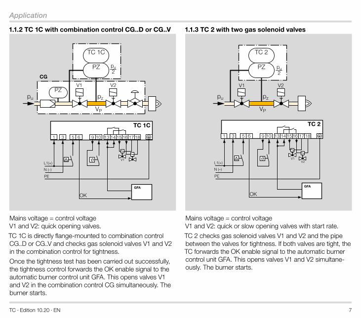
1 .1 .2 TC 1C with combination control CG . .D or CG . .V
V1
pu2
CG
V1 V2
PZ
pu pz
TC 1C
PZ
VP
TC 1C
9
OK
GFA
Mains voltage = control voltage V1 and V2: quick opening valves.
TC 1C is directly flange-mounted to combination control CG..D or CG..V and checks gas solenoid valves V1 and V2 in the combination control for tightness.
Once the tightness test has been carried out successfully, the tightness control forwards the OK enable signal to the automatic burner control unit GFA. This opens valves V1 and V2 in the combination control CG simultaneously. The burner starts.
1 .1 .3 TC 2 with two gas solenoid valves
V2V1
pu2
V1 V2
PZ
pu pz
TC 2
VP
TC 2
9
OK
GFA
Mains voltage = control voltage V1 and V2: quick or slow opening valves with start rate.
TC 2 checks gas solenoid valves V1 and V2 and the pipe between the valves for tightness. If both valves are tight, the TC forwards the OK enable signal to the automatic burner control unit GFA. This opens valves V1 and V2 simultane-ously. The burner starts.
TC · Edition 10.20 · EN 8
Application
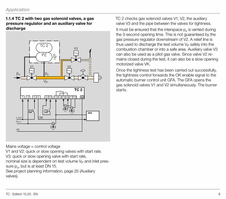
1 .1 .4 TC 2 with two gas solenoid valves, a gas pressure regulator and an auxiliary valve for discharge
GFAV1
pu2
V1 V2
PZ
pu pz
TC 2V3
VP
TC 2
OK
V2
9
V3
Mains voltage = control voltage V1 and V2: quick or slow opening valves with start rate. V3: quick or slow opening valve with start rate, nominal size is dependent on test volume VP and inlet pres-sure pu, but is at least DN 15. See project planning information, page 25 (Auxiliary valves).
TC 2 checks gas solenoid valves V1, V2, the auxiliary valve V3 and the pipe between the valves for tightness.
It must be ensured that the interspace pz is vented during the 3-second opening time. This is not guaranteed by the gas pressure regulator downstream of V2. A relief line is thus used to discharge the test volume VP safely into the combustion chamber or into a safe area. Auxiliary valve V3 can also be used as a pilot gas valve. Since valve V2 re-mains closed during the test, it can also be a slow opening motorized valve VK.
Once the tightness test has been carried out successfully, the tightness control forwards the OK enable signal to the automatic burner control unit GFA. The GFA opens the gas solenoid valves V1 and V2 simultaneously. The burner starts.
TC · Edition 10.20 · EN 9
Application
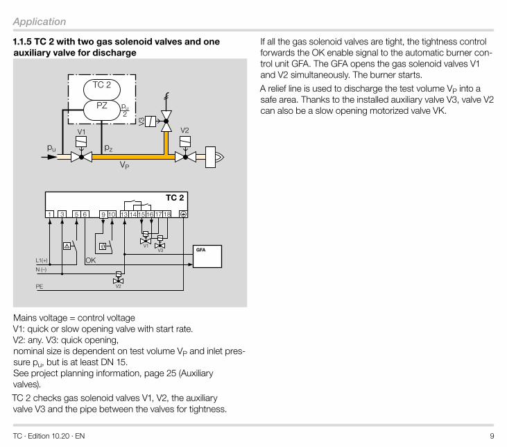
1 .1 .5 TC 2 with two gas solenoid valves and one auxiliary valve for discharge
pu2
V1 V2
PZ
pu pz
TC 2
V3
VP
GFAV1
TC 2
OK
9
V3
V2
Mains voltage = control voltage V1: quick or slow opening valve with start rate. V2: any. V3: quick opening, nominal size is dependent on test volume VP and inlet pres-sure pu, but is at least DN 15. See project planning information, page 25 (Auxiliary valves).
TC 2 checks gas solenoid valves V1, V2, the auxiliary valve V3 and the pipe between the valves for tightness.
If all the gas solenoid valves are tight, the tightness control forwards the OK enable signal to the automatic burner con-trol unit GFA. The GFA opens the gas solenoid valves V1 and V2 simultaneously. The burner starts.
A relief line is used to discharge the test volume VP into a safe area. Thanks to the installed auxiliary valve V3, valve V2 can also be a slow opening motorized valve VK.
TC · Edition 10.20 · EN 10
Application
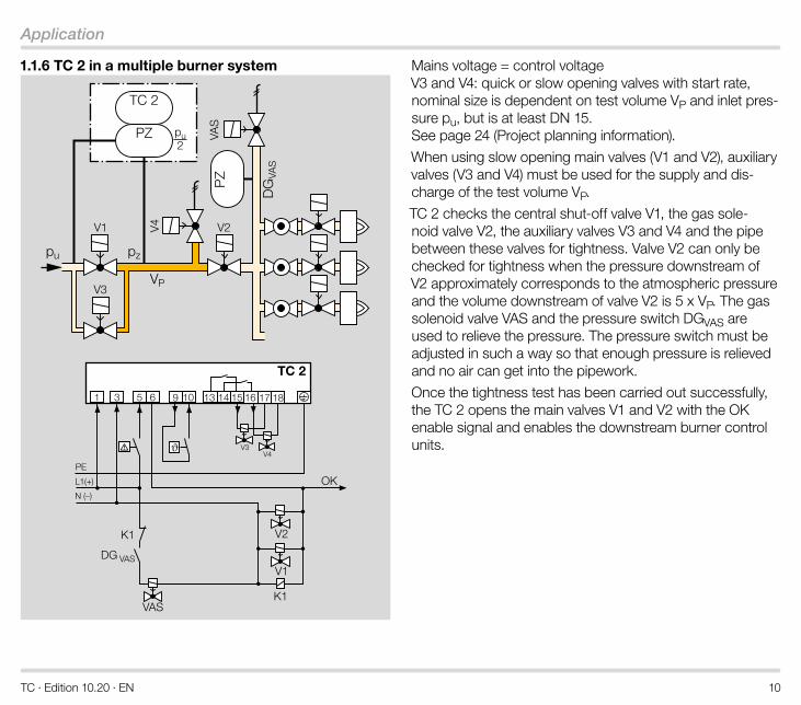
1 .1 .6 TC 2 in a multiple burner system
V4V3
pu2
V1 V2
PZ
pu pz
TC 2
K1
DG VAS
VAS
V3
V4
VAS
DG
VAS
PZ
VP
TC 2
OK
K1
V1
V2
9
Mains voltage = control voltage V3 and V4: quick or slow opening valves with start rate, nominal size is dependent on test volume VP and inlet pres-sure pu, but is at least DN 15. See page 24 (Project planning information).
When using slow opening main valves (V1 and V2), auxiliary valves (V3 and V4) must be used for the supply and dis-charge of the test volume VP.
TC 2 checks the central shut-off valve V1, the gas sole-noid valve V2, the auxiliary valves V3 and V4 and the pipe between these valves for tightness. Valve V2 can only be checked for tightness when the pressure downstream of V2 approximately corresponds to the atmospheric pressure and the volume downstream of valve V2 is 5 x VP. The gas solenoid valve VAS and the pressure switch DGVAS are used to relieve the pressure. The pressure switch must be adjusted in such a way so that enough pressure is relieved and no air can get into the pipework.
Once the tightness test has been carried out successfully, the TC 2 opens the main valves V1 and V2 with the OK enable signal and enables the downstream burner control units.
TC · Edition 10.20 · EN 11
Application
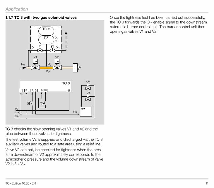
1 .1 .7 TC 3 with two gas solenoid valves
TC 3
OK
9
V1 V2
pu pz
VP
PZ
TC 3
pu2
pu pd
GFA
V1
V2
TC 3 checks the slow opening valves V1 and V2 and the pipe between these valves for tightness.
The test volume VP is supplied and discharged via the TC 3 auxiliary valves and routed to a safe area using a relief line.
Valve V2 can only be checked for tightness when the pres-sure downstream of V2 approximately corresponds to the atmospheric pressure and the volume downstream of valve V2 is 5 x VP.
Once the tightness test has been carried out successfully, the TC 3 forwards the OK enable signal to the downstream automatic burner control unit. The burner control unit then opens gas valves V1 and V2.
TC · Edition 10.20 · EN 12
Application
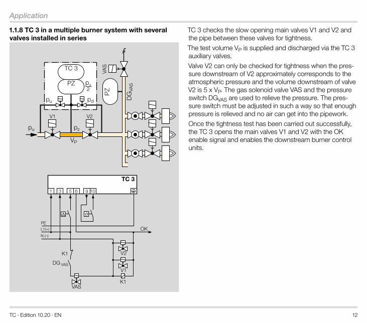
1 .1 .8 TC 3 in a multiple burner system with several valves installed in series
K1
DG VAS
VAS
VAS
DG
VAS
PZ
TC 3
OK
9
V1 V2
pu pz
VP
PZ
TC 3
pu2
pu pd
K1
V1
V2
TC 3 checks the slow opening main valves V1 and V2 and the pipe between these valves for tightness.
The test volume VP is supplied and discharged via the TC 3 auxiliary valves.
Valve V2 can only be checked for tightness when the pres-sure downstream of V2 approximately corresponds to the atmospheric pressure and the volume downstream of valve V2 is 5 x VP. The gas solenoid valve VAS and the pressure switch DGVAS are used to relieve the pressure. The pres-sure switch must be adjusted in such a way so that enough pressure is relieved and no air can get into the pipework.
Once the tightness test has been carried out successfully, the TC 3 opens the main valves V1 and V2 with the OK enable signal and enables the downstream burner control units.
TC · Edition 10.20 · EN 13
Certification
2 CertificationCertificates – see www.docuthek.com
Certified to SIL and PL
For systems up to SIL 3 pursuant to EN 61508 and PL e pursuant to ISO 13849. See page 34 (Safety-specific characteristic values for SIL and PL).
EU certified
• 2014/35/EU (LVD), Low Voltage Directive
• 2014/30/EU (EMC), Electromagnetic Compatibility Direc-tive
• 2011/65/EU, RoHS II
• 2015/863/EU, RoHS III
• (EU) 2016/426 (GAR), Gas Appliances Regulation
• EN 1643:2014
• EN 60730-2-5:2015
• EN 61508:2010, Parts 1–7 for Safety Integrity Level SIL 3
AGA approved
AGA
Australian Gas Association, Approval No.: 8618. www.aga.asn.au
Eurasian Customs Union
The products TC meet the technical specifications of the Eurasian Customs Union.
TC · Edition 10.20 · EN 14
Function
3 Function
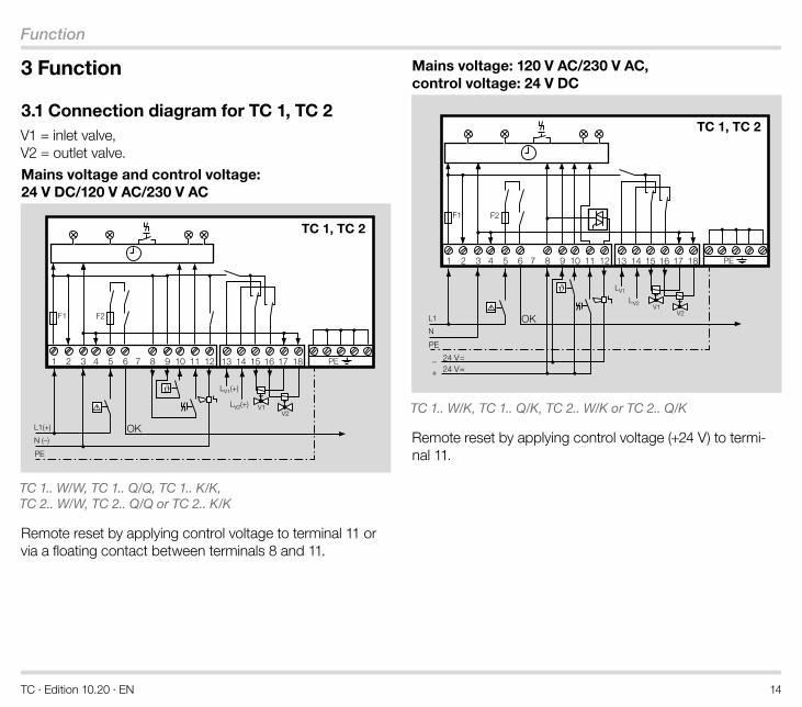
3 .1 Connection diagram for TC 1, TC 2V1 = inlet valve, V2 = outlet valve.
Mains voltage and control voltage: 24 V DC/120 V AC/230 V AC
OK
V2
TC 1, TC 2
V1
TC 1.. W/W, TC 1.. Q/Q, TC 1.. K/K, TC 2.. W/W, TC 2.. Q/Q or TC 2.. K/K
Remote reset by applying control voltage to terminal 11 or via a floating contact between terminals 8 and 11.
Mains voltage: 120 V AC/230 V AC, control voltage: 24 V DC
TC 1, TC 2
V2V1
OK
TC 1.. W/K, TC 1.. Q/K, TC 2.. W/K or TC 2.. Q/K
Remote reset by applying control voltage (+24 V) to termi-nal 11.
TC · Edition 10.20 · EN 15
Function
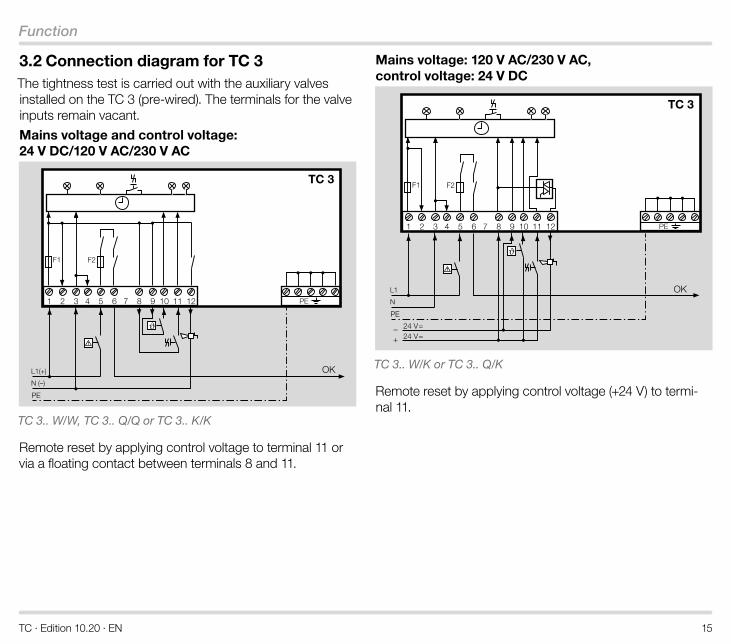
3 .2 Connection diagram for TC 3The tightness test is carried out with the auxiliary valves installed on the TC 3 (pre-wired). The terminals for the valve inputs remain vacant.
Mains voltage and control voltage: 24 V DC/120 V AC/230 V AC
OK
TC 3
TC 3.. W/W, TC 3.. Q/Q or TC 3.. K/K
Remote reset by applying control voltage to terminal 11 or via a floating contact between terminals 8 and 11.
Mains voltage: 120 V AC/230 V AC, control voltage: 24 V DC
OK
TC 3
TC 3.. W/K or TC 3.. Q/K
Remote reset by applying control voltage (+24 V) to termi-nal 11.
TC · Edition 10.20 · EN 16
Function
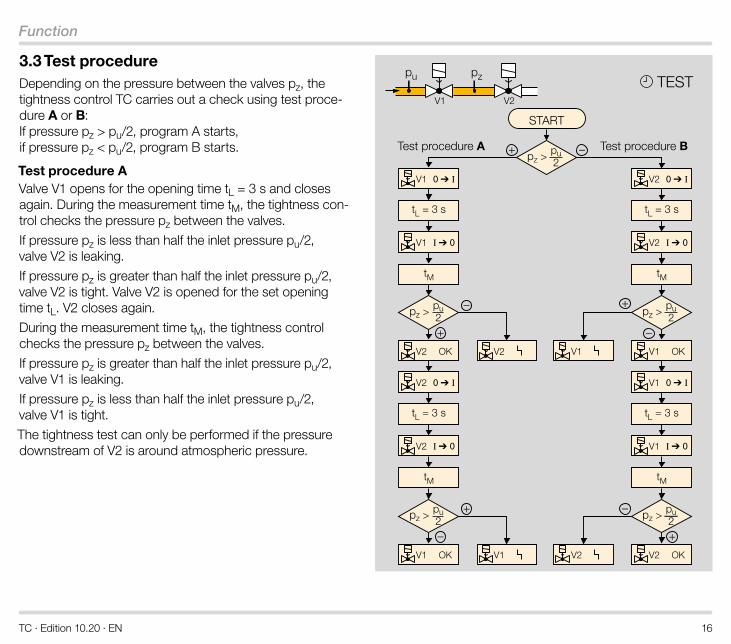
3 .3 Test procedureDepending on the pressure between the valves pz, the tightness control TC carries out a check using test proce-dure A or B: If pressure pz > pu/2, program A starts, if pressure pz < pu/2, program B starts.
Test procedure AValve V1 opens for the opening time tL = 3 s and closes again. During the measurement time tM, the tightness con-trol checks the pressure pz between the valves.
If pressure pz is less than half the inlet pressure pu/2, valve V2 is leaking.
If pressure pz is greater than half the inlet pressure pu/2, valve V2 is tight. Valve V2 is opened for the set opening time tL. V2 closes again.
During the measurement time tM, the tightness control checks the pressure pz between the valves.
If pressure pz is greater than half the inlet pressure pu/2, valve V1 is leaking.
If pressure pz is less than half the inlet pressure pu/2, valve V1 is tight.
The tightness test can only be performed if the pressure downstream of V2 is around atmospheric pressure.
tL = 3 s
tM
–
–+
+
+ –
tM
pz >pu2
V1
V1
V1
pz >pu2
V2 OK V2 V1 OK
V2
V2
tL = 3 s
tL = 3 s
tM
+
–
tM
pz >pu2+
–
V2
V2
V2
pz >pu2
V1 OK V1 V2 OK
V1
V1
tL = 3 s
pu pz
pz >pu2
TESTV1 V2
Test procedure A Test procedure B
START
TC · Edition 10.20 · EN 17
Function
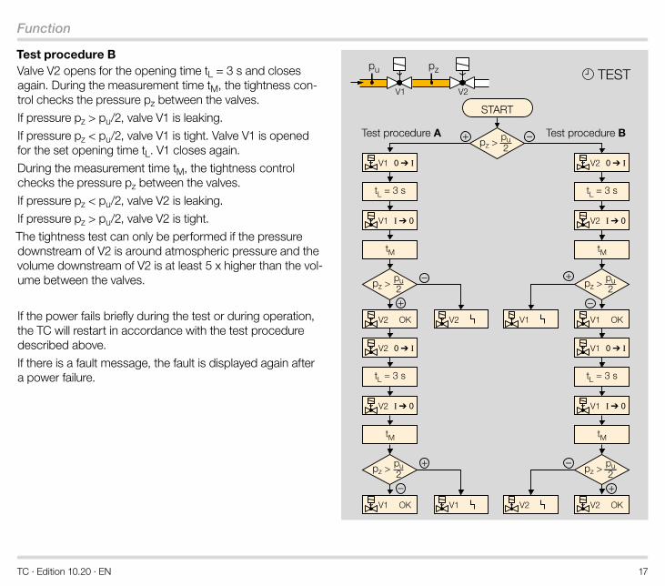
Test procedure BValve V2 opens for the opening time tL = 3 s and closes again. During the measurement time tM, the tightness con-trol checks the pressure pz between the valves.
If pressure pz > pu/2, valve V1 is leaking.
If pressure pz < pu/2, valve V1 is tight. Valve V1 is opened for the set opening time tL. V1 closes again.
During the measurement time tM, the tightness control checks the pressure pz between the valves.
If pressure pz < pu/2, valve V2 is leaking.
If pressure pz > pu/2, valve V2 is tight.
The tightness test can only be performed if the pressure downstream of V2 is around atmospheric pressure and the volume downstream of V2 is at least 5 x higher than the vol-ume between the valves.
If the power fails briefly during the test or during operation, the TC will restart in accordance with the test procedure described above.
If there is a fault message, the fault is displayed again after a power failure.
tL = 3 s
tM
–
–+
+
+ –
tM
pz >pu2
V1
V1
V1
pz >pu2
V2 OK V2 V1 OK
V2
V2
tL = 3 s
tL = 3 s
tM
+
–
tM
pz >pu2+
–
V2
V2
V2
pz >pu2
V1 OK V1 V2 OK
V1
V1
tL = 3 s
pu pz
pz >pu2
TESTV1 V2
Test procedure A Test procedure B
START
TC · Edition 10.20 · EN 18
Function
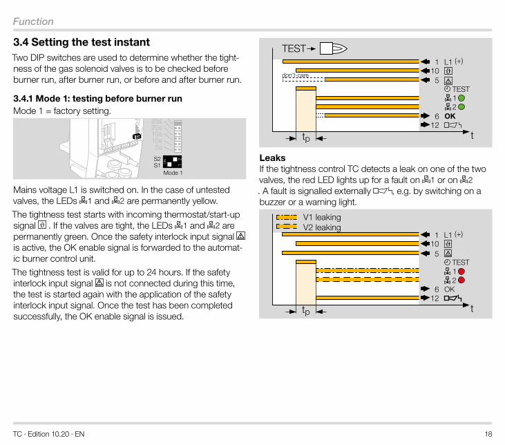
3 .4 Setting the test instantTwo DIP switches are used to determine whether the tight-ness of the gas solenoid valves is to be checked before burner run, after burner run, or before and after burner run.
3 .4 .1 Mode 1: testing before burner runMode 1 = factory setting.
5s10s15s20s25s30s
Mode 1
Mains voltage L1 is switched on. In the case of untested valves, the LEDs 1 and 2 are permanently yellow.
The tightness test starts with incoming thermostat/start-up signal . If the valves are tight, the LEDs 1 and 2 are permanently green. Once the safety interlock input signal is active, the OK enable signal is forwarded to the automat-ic burner control unit.
The tightness test is valid for up to 24 hours. If the safety interlock input signal is not connected during this time, the test is started again with the application of the safety interlock input signal. Once the test has been completed successfully, the OK enable signal is issued.
t
L1 (+)
TEST
OK
110
12
12
tp
don’t-care5
6
TEST
Leaks If the tightness control TC detects a leak on one of the two valves, the red LED lights up for a fault on 1 or on 2. A fault is signalled externally , e.g. by switching on a buzzer or a warning light.
L1 (+)
TEST
OK
t
110
612
12
tp
5
V1 leakingV2 leaking
TC · Edition 10.20 · EN 19
Function
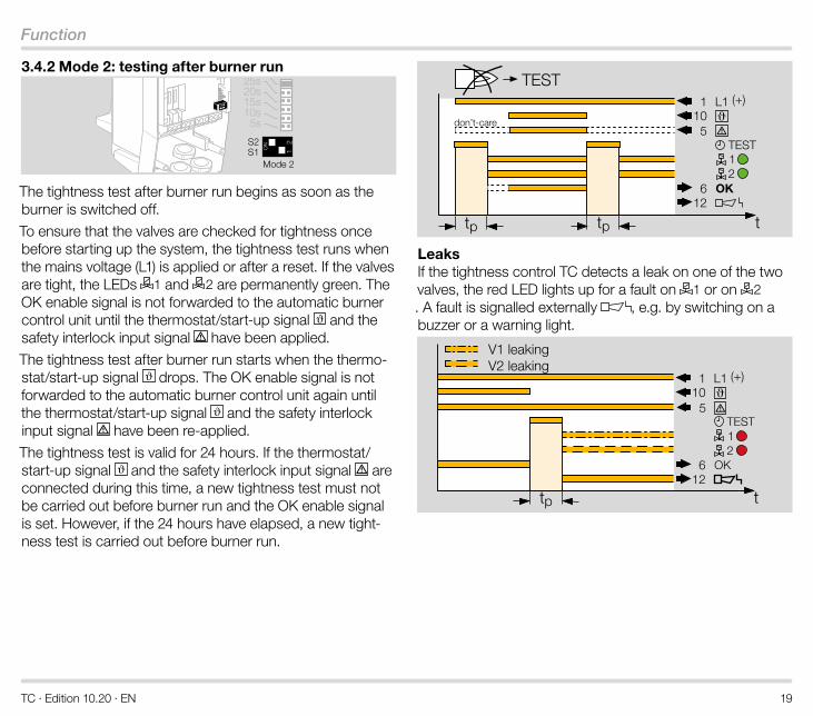
3 .4 .2 Mode 2: testing after burner run
5s10s15s20s25s30s
Mode 2
The tightness test after burner run begins as soon as the burner is switched off.
To ensure that the valves are checked for tightness once before starting up the system, the tightness test runs when the mains voltage (L1) is applied or after a reset. If the valves are tight, the LEDs 1 and 2 are permanently green. The OK enable signal is not forwarded to the automatic burner control unit until the thermostat/start-up signal and the safety interlock input signal have been applied.
The tightness test after burner run starts when the thermo-stat/start-up signal drops. The OK enable signal is not forwarded to the automatic burner control unit again until the thermostat/start-up signal and the safety interlock input signal have been re-applied.
The tightness test is valid for 24 hours. If the thermostat/start-up signal and the safety interlock input signal are connected during this time, a new tightness test must not be carried out before burner run and the OK enable signal is set. However, if the 24 hours have elapsed, a new tight-ness test is carried out before burner run.
t
L1 (+)
TEST
OK
110
612
12
TEST
don’t-care5
tp tp
Leaks If the tightness control TC detects a leak on one of the two valves, the red LED lights up for a fault on 1 or on 2. A fault is signalled externally , e.g. by switching on a buzzer or a warning light.
V1 leakingV2 leaking
L1 (+)
TEST
OK
t
110
612
12
tp
5
TC · Edition 10.20 · EN 20
Function
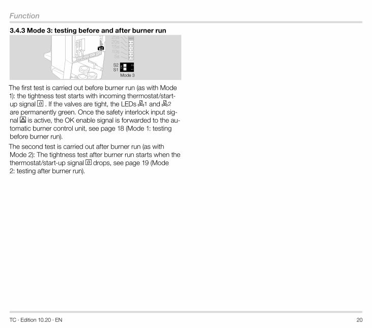
3 .4 .3 Mode 3: testing before and after burner run
5s10s15s20s25s30s
Mode 3
The first test is carried out before burner run (as with Mode 1): the tightness test starts with incoming thermostat/start-up signal . If the valves are tight, the LEDs 1 and 2 are permanently green. Once the safety interlock input sig-nal is active, the OK enable signal is forwarded to the au-tomatic burner control unit, see page 18 (Mode 1: testing before burner run).
The second test is carried out after burner run (as with Mode 2): The tightness test after burner run starts when the thermostat/start-up signal drops, see page 19 (Mode 2: testing after burner run).
TC · Edition 10.20 · EN 21
Function
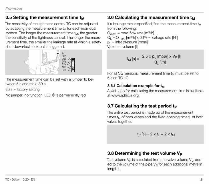
3 .5 Setting the measurement time tM The sensitivity of the tightness control TC can be adjusted by adapting the measurement time tM for each individual system. The longer the measurement time tM, the greater the sensitivity of the tightness control. The longer the meas-urement time, the smaller the leakage rate at which a safety shut-down/fault lock-out is triggered.
tM
5s10s15s20s25s30s
The measurement time can be set with a jumper to be-tween 5 s and max. 30 s.
30 s = factory setting
No jumper: no function. LED is permanently red.
3 .6 Calculating the measurement time tM If a leakage rate is specified, find the measurement time tM from the following: Qmax. = max. flow rate [m3/h] QL = Qmax. [m3/h] x 0.1% = leakage rate [l/h] pu = inlet pressure [mbar] VP = test volume [l]
tM [s] =2,5 x pu [mbar] x VP [l]
QL [l/h]
For all CG versions, measurement time tM must be set to 5 s on TC 1C.
3 .6 .1 Calculation example for tM A web app for calculating the measurement time is available at www.adlatus.org.
3 .7 Calculating the test period tP The entire test period is made up of the measurement times tM of both valves and the fixed opening time tL of both valves together.
tP [s] = 2 x tL + 2 x tM
3 .8 Determining the test volume VP Test volume VP is calculated from the valve volume VV, add-ed to the volume of the pipe VR for each additional metre in length L.
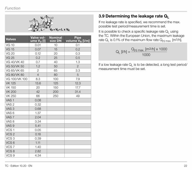
TC · Edition 10.20 · EN 22
Function
L VP = VV + L x VR
VPV1
V2
Valves Valve vol-ume VV [l]
Nominal size DN
Pipe volume VR [l/m]
VG 10 0.01 10 0.1VG 15 0.07 15 0.2VG 20 0.12 20 0.3VG 25 0.2 25 0.5VG 40/VK 40 0.7 40 1.3VG 50/VK 50 1.2 50 2VG 65/VK 65 2 65 3.3VG 80/VK 80 4 80 5VG 100/VK 100 8.3 100 7.9VK 125 13.6 125 12.3VK 150 20 150 17.7VK 200 42 200 31.4VK 250 66 250 49VAS 1 0.08VAS 2 0.32VAS 3 0.68VAS 6 1.37VAS 7 2.04VAS 8 3.34VAS 9 5.41VCS 1 0.05VCS 2 0.18VCS 3 0.39VCS 6 1.11VCS 7 1.40VCS 8 2.82VCS 9 4.34
3 .9 Determining the leakage rate QL If no leakage rate is specified, we recommend the max. possible test period/measurement time is set.
It is possible to check a specific leakage rate QL using the TC. Within the European Union, the maximum leakage rate QL is 0.1% of the maximum flow rate Q(n) max. [m3/h].
Q(n) max. [m3/h] x 1000
1000QL [l/h] =
If a low leakage rate QL is to be detected, a long test period/measurement time must be set.
TC · Edition 10.20 · EN 23
Selection
4 Selection
4 .1 ProFiA web app selecting the correct product is available at www.adlatus.org.
4 .2 Selection table
Option TC 1V TC 1C TC 2 TC 3Attachment type 1V 1C 2 3Pipe connection R, N R, NInlet pressure 05 05 05 05Mains voltage1) W, Q, K W, Q, K W, Q, K W, Q, K
Control voltage1) 2) /W, /Q, /K
/W, /Q, /K
/W, /Q, /K
/W, /Q, /K
1) Mains voltage = control voltage: TC..W/W, TC..Q/Q, TC..K/K2) 24 V DC control voltage for 120 V AC or 230 V AC mains voltage:
TC..W/K, TC..Q/K
Order exampleTC 1V05W/K
4 .3 Type code
4 .3 .1 Type code TC 1V TC Tightness control
1V For attachment to valVario
05 pu max. 500 mbar
W Mains voltage 230 V AC, 50/60 Hz
Q Mains voltage 120 V AC, 50/60 Hz
K Mains voltage 24 V DC
/W Control voltage: 230 V AC, 50/60 Hz
/Q Control voltage: 120 V AC, 50/60 Hz
/K Control voltage: 24 V DC
4 .3 .2 Type code TC 1C, TC 2, TC 3TC Tightness control
1C For attachment to CG
2 For quick opening individual valves
3 For quick or slow opening individual valves
R Rp internal thread
N NPT internal thread
05 pu max. 500 mbar
W Mains voltage 230 V AC, 50/60 Hz
Q Mains voltage 120 V AC, 50/60 Hz
K Mains voltage 24 V DC
/W Control voltage: 230 V AC, 50/60 Hz
/Q Control voltage: 120 V AC, 50/60 Hz
/K Control voltage: 24 V DC
TC · Edition 10.20 · EN 24
Project planning information
5 Project planning information
5 .1 Start rateThe tightness control TC requires a minimum start rate in order to carry out tightness tests on slow opening valves: up to 5 l (1.3 gal) test volume VP = 5% of maximum flow rate Qmax., up to 12 l (3.12 gal) test volume VP = 10% of maximum flow rate Qmax..
5 .2 InstallationInstallation in the vertical or horizontal position, housing cov-er/indicators must not point upwards or downwards. The electrical connection should preferably be pointing down-wards or towards the outlet.
Condensation must not be allowed to get into the housing.
The unit may only be stored/installed in enclosed rooms/buildings.
The housing must not be in contact with masonry. Minimum clearance 20 mm (0.8").
5 .3 TC 1V for solenoid valves for gas VAS, VCxThe valve actuator cannot be rotated on gas solenoid valves with a proof of closure switch VCx..S or VCx..G.
When using a valve/pressure regulator combination VCG/VCV/VCH, the pressure regulator must be activated with air during the entire test period tP. This ensures that the space between the valves can be filled and vented.
A TC and a bypass/pilot gas valve cannot be fitted together on the same attachment side of the VAS or VCx.
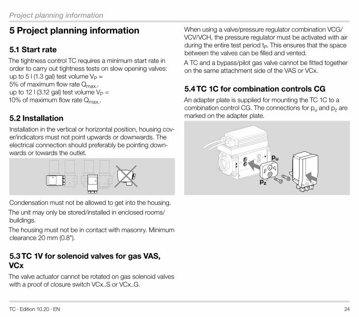
5 .4 TC 1C for combination controls CGAn adapter plate is supplied for mounting the TC 1C to a combination control CG. The connections for pu and pz are marked on the adapter plate.
pu
pz
TC · Edition 10.20 · EN 25
Project planning information
5 .5 Mounting TC 2The TC is connected to the inlet pressure connection pu and the interspace pressure connection pz of the inlet valve.
An adapter plate is supplied for mounting the TC 2 to a gas solenoid valve. The connections for pu and pz are marked on the adapter plate.
TC 2..R: Rp ¼TC 2..N: ¼ NPT
pu
pz
pz
We recommend using Ermeto screw couplings to attach the adapter plate to the gas solenoid valve.
Connect the interspace pressure connection pz on the adapter plate to the space between the valves using a 12 x 1.5 or 8 x 1 pipe.
pu
pz
pz
5 .6 Mounting TC 3The TC is connected to the inlet pressure connection pu, the interspace pressure connection pz and the outlet pres-sure connection pd of the inlet valve.
Ensure that connections pu, pz and pd on the TC are not reversed.
pz
pz
pdpu
TC 3..R: Rp ¼TC 3..N: ¼ NPT
Use a 12 x 1.5 or 8 x 1 pipe for the pipe connections.
5 .7 Determining the relief line sizeThe nominal diameter of the relief line should be large enough to discharge the test volume VP. The cross-sec-tion of the relief line should be 5 times the sum of the cross-sections of all pipes whose volume is intended to be discharged via the relief line.
5 .8 Auxiliary valvesOn slow opening valves without start rate or pneumatically operated valves, the test volume can be supplied or dis-charged via auxiliary valves if discharge into the furnace chamber is impossible for process reasons.
TC · Edition 10.20 · EN 26
Project planning information
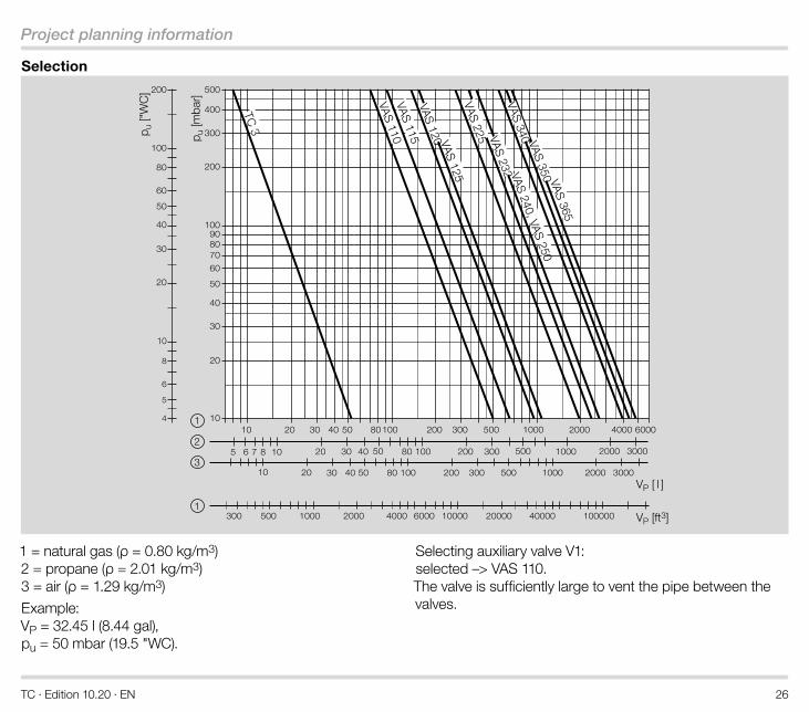
Selection
1
20
30
40
50
60
80
4
5
6
8
100
200 500
400
300
200
100
8090
60
70
50
40
30
20
1010
10
10
85 6 7
20
20
20
30
30
30
40
40
40
50
50
50
80
80
80
100 200
200
200
300
300
300
500
500
500
1000
1000
1000
2000
2000
2000
3000
3000
4000 6000
100
100
300 500 1000 2000 4000 6000 10000 20000 40000 100000
10
3
2
1
p u ["
WC
]
p u [m
bar]
VP [ft3]
VP [ l ]
VAS 110
TC 3
VAS 115 VAS 125VAS 225 VAS 232VAS 340 VAS 350VAS 240, VAS 250
VAS 365
VAS 120
1 = natural gas (ρ = 0.80 kg/m3) 2 = propane (ρ = 2.01 kg/m3) 3 = air (ρ = 1.29 kg/m3)
Example: VP = 32.45 l (8.44 gal), pu = 50 mbar (19.5 "WC).
Selecting auxiliary valve V1: selected –> VAS 110. The valve is sufficiently large to vent the pipe between the valves.
TC · Edition 10.20 · EN 27
Project planning information
5 .9 Electrical connection of TC 1, TC 2For the electrical connection of the TC to valves with a plug, a socket can be supplied as an accessory, see page 28 (Accessories).
TC · Edition 10.20 · EN 28
Accessories
6 Accessories
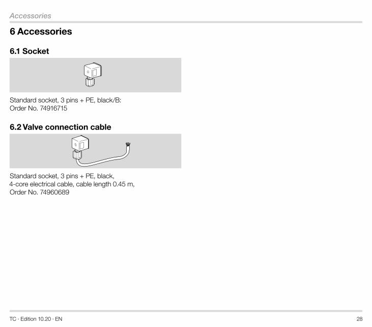
6 .1 Socket
Standard socket, 3 pins + PE, black/B: Order No. 74916715
6 .2 Valve connection cable
Standard socket, 3 pins + PE, black, 4-core electrical cable, cable length 0.45 m, Order No. 74960689
TC · Edition 10.20 · EN 29
Technical data
7 Technical data
7 .1 Ambient conditionsIcing, condensation and dew in and on the unit are not per-mitted.
Avoid direct sunlight or radiation from red-hot surfaces on the unit. Note the maximum medium and ambient temper-atures!
Avoid corrosive influences, e.g. salty ambient air or SO2.
The unit may only be stored/installed in enclosed rooms/buildings.
The unit is suitable for a maximum installation height of 2000 m AMSL.
Ambient temperature: -20 to +60°C (-4 to +140°F), no con-densation permitted. Long-term use in the upper ambient temperature range ac-celerates the ageing of the elastomer materials and reduces the service life (please contact manufacturer).
Storage temperature: -20 to +40°C (-4 to +104°F).
Enclosure: IP 65.
This unit is not suitable for cleaning with a high-pressure cleaner and/or cleaning products.
7 .2 Mechanical dataGas types: natural gas, LPG (gaseous), biogas (max. 0.1 %-by-vol. H2S) or clean air. The gas must be clean and dry in all temperature conditions and must not contain con-densate.
Medium temperature = ambient temperature.
Inlet pressure pu: 10 to 500 mbar (3.9 to 195 "WC).
Measurement time tM: 5 to 30 s, adjustable. Set at the fac-tory to 30 s.
Valve opening time: 3 s.
Housing made of impact-resistant plastic.
Connectors: aluminium.
Weight: TC 1V: 215 g (0.47 lbs), TC 2 with adapter: 260 g (0.57 lbs), TC 3: 420 g (0.92 lbs).
7 .3 Electrical dataMains voltage and control voltage: 120 V AC, -15/+10%, 50/60 Hz, 230 V AC, -15/+10%, 50/60 Hz, 24 V DC, ±20%.
Power consumption (all LEDs green): 5.5 W at 120 V AC and 230 V AC, 2 W at 24 V DC, TC 3: plus 8 VA for an auxiliary valve.
Fine-wire fuse: 5 A, slow-acting, H, 250 V, pursuant to IEC 60127-2/5, F1: protection of valve outputs (terminals 15 and 16), fault signal (terminal 12) and supply of the control inputs (termi-nals 2, 7 and 8). F2: protection of safety interlock/controller enable signal (terminal 6).
The input current at terminal 1 must not exceed 5 A.
Max. load current (terminal 6) for safety interlock/controller enable and valve outputs (terminals 15 and 16): at 230/120 V AC mains voltage, max. 3 A resistive load; at 24 V DC mains voltage, max. 5 A resistive load.
TC · Edition 10.20 · EN 30
Technical data
Fault signal (terminal 12): fault output at 120 V AC/230 V AC/24 V DC mains and con-trol voltage: max. 5 A, fault output at 120 V AC/230 V AC mains voltage, 24 V DC control voltage: max. 100 mA.
TC switching cycles: 250,000 pursuant to EN 13611.
Reset: using a button on the device or by remote reset.
Length of connection cable: at 230 V AC/120 V AC: any, at 24 V DC (supply connected to PE): max. 10 m permitted, at 24 V DC (supply not connected to PE): any.
5 cable glands: M16 x 1.5.
Electrical connection: Cable cross-section: min. 0.75 mm2 (AWG 19), max. 2.5 mm2 (AWG 14).
TC · Edition 10.20 · EN 31
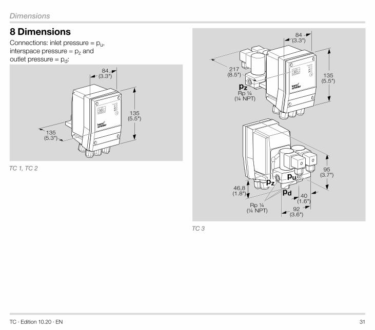
Dimensions
8 DimensionsConnections: inlet pressure = pu, interspace pressure = pz and outlet pressure = pd:
1
2
Power
135(5.5")
135(5.3")
84(3.3")
TC 1, TC 2
1
2
Power
pd
pupz
pz
135(5.5")
217(8.5")
84(3.3")
92(3.6")
40(1.6")
95(3.7")
46,8(1.8")
Rp ¼(¼ NPT)
Rp ¼(¼ NPT)
TC 3
TC · Edition 10.20 · EN 32
Converting units
9 Converting unitsSee www.adlatus.org
TC · Edition 10.20 · EN 33
Indicators and operating controls
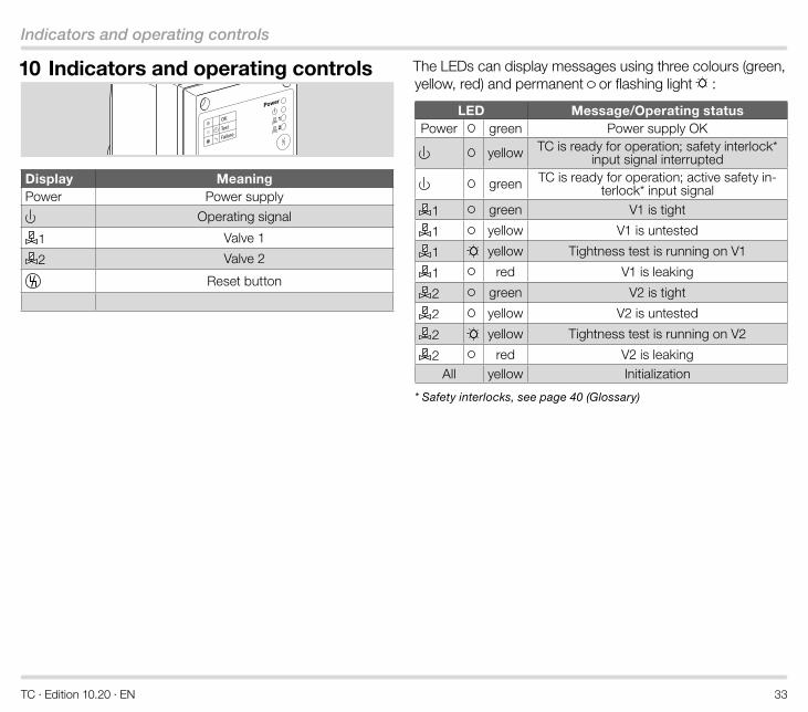
10 Indicators and operating controls
1
2
Power
Display MeaningPower Power supply
Operating signal
1 Valve 1
2 Valve 2
Reset button
The LEDs can display messages using three colours (green, yellow, red) and permanent or flashing light :
LED Message/Operating statusPower green Power supply OK
yellow TC is ready for operation; safety interlock* input signal interrupted
green TC is ready for operation; active safety in-terlock* input signal
1 green V1 is tight
1 yellow V1 is untested
1 yellow Tightness test is running on V1
1 red V1 is leaking
2 green V2 is tight
2 yellow V2 is untested
2 yellow Tightness test is running on V2
2 red V2 is leakingAll yellow Initialization
* Safety interlocks, see page 40 (Glossary)
TC · Edition 10.20 · EN 34
Safety-specific characteristic values for SIL and PL
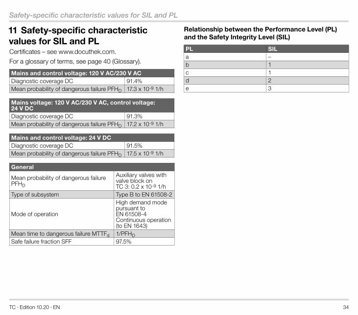
11 Safety-specific characteristic values for SIL and PLCertificates – see www.docuthek.com.
For a glossary of terms, see page 40 (Glossary).
Mains and control voltage: 120 V AC/230 V ACDiagnostic coverage DC 91.4%Mean probability of dangerous failure PFHD 17.3 x 10⁻⁹ 1/h
Mains voltage: 120 V AC/230 V AC, control voltage: 24 V DCDiagnostic coverage DC 91.3%Mean probability of dangerous failure PFHD 17.2 x 10⁻⁹ 1/h
Mains and control voltage: 24 V DCDiagnostic coverage DC 91.5%Mean probability of dangerous failure PFHD 17.5 x 10⁻⁹ 1/h
General
Mean probability of dangerous failure PFHD
Auxiliary valves with valve block on TC 3: 0.2 x 10⁻⁹ 1/h
Type of subsystem Type B to EN 61508-2
Mode of operation
High demand mode pursuant to EN 61508-4 Continuous operation (to EN 1643)
Mean time to dangerous failure MTTFd 1/PFHDSafe failure fraction SFF 97.5%
Relationship between the Performance Level (PL) and the Safety Integrity Level (SIL)
PL SILa –b 1c 1d 2e 3
TC · Edition 10.20 · EN 35
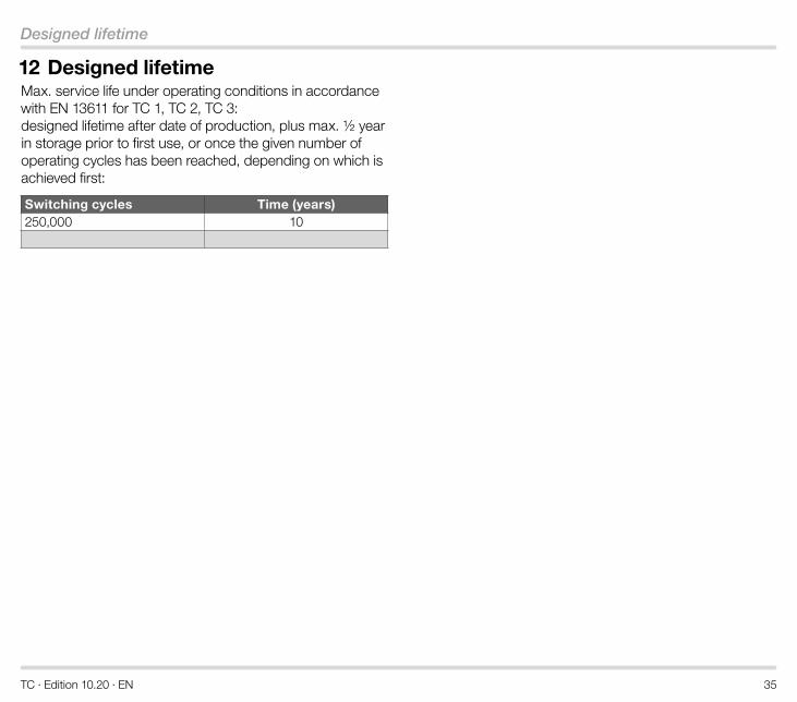
Designed lifetime
12 Designed lifetimeMax. service life under operating conditions in accordance with EN 13611 for TC 1, TC 2, TC 3: designed lifetime after date of production, plus max. ½ year in storage prior to first use, or once the given number of operating cycles has been reached, depending on which is achieved first:
Switching cycles Time (years)250,000 10
TC · Edition 10.20 · EN 36
Safety information in accordance with EN 61508-2
13 Safety information in accordance with EN 61508-2
13 .1 General
Scope of applicationMachinery Directive (2006/42/EC) with the applicable har-monized standards as set out in “Industrial thermoprocess-ing equipment – Part 2: Safety requirements for combustion and fuel handling systems” (EN 746-2).
For further information, see page 4 (Application) and on the certificates, see www.docuthek.com.
Aim
The TC 1, TC 2, TC 3 is a control unit pursuant to EN 60730-2-5, Section 6.3.103.
Type of action:The automatic action of the TC 1, TC 2, TC 3 corresponds to Type 2 pursuant to EN 60730-1, Section 1/5.
Mode of operation
The TC 1, TC 2, TC 3 is capable of continuous operation and thus fulfils the characteristic of automatic action type 2.AD pursuant to EN 60730-2-5, Section 6.4.104.
Switching off the safety-relevant output signals: the safe-ty-relevant output signals are switched off via relays. This is a micro-disconnection pursuant to EN 60730-1, Sections 6.4.3.2 and 6.9.2.
Fault lock-out Non-volatile fault lock-out, action type 2.V pursuant to EN 60730-2-5, Section 6.4.101.
Other classifications:Load
The outputs of the TC are primarily designed for resistive loads with a power factor ≥ 0.95.
Automatic cycles
The tightness control is designed for more than 250,000 automatic cycles.
Fault detection time
On demand
Software class
C (operates in a similar double-channel architecture with comparison)
Electrical data:Safety class
Safety class
Overvoltage category
Overvoltage category III (hard wiring/industrial application)
Pollution degree
Pollution degree 2 (≥ IP 65).
TC · Edition 10.20 · EN 37
Safety information in accordance with EN 61508-2
13 .2 Interfaces
Electrical wiringAttachment type X to EN 60730-1.
230 V AC, 120 V AC
Connection:
The TC 1, TC 2, TC 3 must be correctly phased in accord-ance with the connection diagrams.
24 V DC
Extra-low voltage (ELV):
If the TC 1, TC 2, TC 3 is supplied with ELV, at which Mi-nus/-/GND are connected to PE, all connected cables must not be longer than 10 m.
If the TC 1, TC 2, TC 3 is supplied with ELV, at which Mi-nus/-/GND are not connected to PE, all connected cables may be longer than 10 m.
Safety extra-low voltage (SELV):
If the TC 1, TC 2, TC 3 is supplied with SELV, all connected components must also fulfil the requirements of SELV.
Protective extra-low voltage (PELV):
If the TC 1, TC 2, TC 3 is supplied with PELV, all connected cables must not be longer than 10 m.
Connection terminals:Supply and control signal terminals
Mains voltage = control voltage 24 V DC, 120 V AC or 230 V AC: power is supplied to the TC via connection terminals 1 (L1 (+)) and 3 (N (-)). Further terminal assignment, see connection diagrams.
120 V AC or 230 V AC mains voltage, 24 V DC control voltage: control voltage is supplied via con-nection terminals 8 (+) and 9 (-).
Terminals for automatic burner control unit and valves
See connection diagrams.
PE wire connection
5 PE terminals for forwarding. Connection to the system PE must be carried out/wired by the user.
Inputs:Safety interlocks (limits)
Input voltage = mains voltage
Thermostat/start-up signal
Input voltage = control voltage
Reset/remote reset
Input voltage = control voltage
Outputs:Safety interlocks (limits) /OK enable signal at 230/120 V AC mains voltage, max. 3 A resistive load; at 24 V DC mains voltage, max. 5 A resistive load.
Valve outputs V1 and V2
at 230/120 V AC mains voltage, max. 3 A resistive load; at 24 V DC mains voltage, max. 5 A resistive load.
Fault signal
at 24 V DC, 120 V AC or 230 V AC mains voltage and con-trol voltage: max. 5 A resistive load,
TC · Edition 10.20 · EN 38
Safety information in accordance with EN 61508-2
at 120 V AC/230 V AC mains voltage and 24 V DC control voltage: max. 100 mA.
13 .3 SIL and PLSafety function
The basic safety function of the TC 1, TC 2, TC 3 is to check that automatic shut-off valves have closed effectively by de-tecting leakage.
Classification
Class C regulating and control functions
Demand mode
High demand mode pursuant to IEC 61508-4
Hardware Fault Tolerance HFT
HFT: N = 0
SIL Safety Integrity Level/PL Performance Level See page 34 (Safety-specific characteristic values for SIL and PL)
TC · Edition 10.20 · EN 39
Maintenance cycles
14 Maintenance cyclesTC requires little servicing.
We recommend a function check once a year, twice a year in the case of biologically produced methane.
TC · Edition 10.20 · EN 40
Glossary
15 Glossary
15 .1 Tightness controlThe term “tightness control” is the product name of product group TC from Elster GmbH. Tightness control TC is a valve proving system (VPS).
15 .2 Valve proving system VPSSystem to check that automatic shut-off valves have closed effectively by detecting leakage. This system is frequently comprised of a program unit, a measuring device, valves and other functional equipment. Valve proving systems for gas burners and gas appliances pursuant to DIN EN 1643 determine whether an automatic shut-off valve has closed on the basis of the detected leakage rate.see EN 1643
15 .3 Safety interlocks (limits)Linking of all the relevant safety-related control and switch-ing equipment for the use of the application. The burner start enable signal is issued via the safety interlock output (terminal 6).
15 .4 Diagnostic coverage DCMeasure of the effectiveness of diagnostics, which may be determined as the ratio between the failure rate of detected dangerous failures and the failure rate of total dangerous failures
NOTE: Diagnostic coverage can exist for the whole or parts of a safety-related system. For example, diagnostic cover-
age could exist for sensors and/or logic system and/or final elements. Unit: % see EN ISO 13849-1
15 .5 Mode of operationHigh demand mode or continuous mode
Operating mode, where the frequency of demands for op-eration made on a safety-related system is greater than one per year or greater than twice the proof-test frequencysee EN 61508-4
15 .6 Hardware fault tolerance HFTA hardware fault tolerance of N means that N + 1 is the minimum number of faults that could cause a loss of the safety functionsee IEC 61508-2
15 .7 Probability of dangerous failure PFHD Value describing the likelihood of dangerous failure per hour of a component for high demand mode or continuous mode. Unit: 1/hsee EN 13611/A2
15 .8 Mean time to dangerous failure MTTFd Expectation of the mean time to dangerous failure
see EN ISO 13849-1:2008
TC · Edition 10.20 · EN
The Honeywell Thermal Solutions family of products includes Honeywell Combustion Safety, Eclipse, Exothermics, Hauck, Kromschröder and Maxon. To learn more about our products, visit ThermalSolutions.honey-well.com or contact your Honeywell Sales Engineer. Elster GmbH Strotheweg 1, D-49504 Lotte T +49 541 1214-0 [email protected] www.kromschroeder.com
Fore more information
© 2020 Elster GmbH
We reserve the right to make tech-nical modifications in the interests of progress.