rohm's sic power device - synergy electronics · rohm’s sic mosfets have outstanding...
TRANSCRIPT

c 2014 ROHM Co.,Ltd. All Rights Reserved Confidential
Power Device Production Division
ROHM's SiC Power Device
Feb 24, 2014

c 2014 ROHM Co.,Ltd. All Rights Reserved Confidential
SiC Power Devices' Hot Applications
SiC devices have been already used in various application because of their superior characteristics over conventional silicon devices
Power supplies (Air Conditioner, IT servers,
EV Charger)
• Mainly used in PFC circuit
• Efficiency improves by 0.5~1.5% with SiC SBD
• Also used in on board charger
for EV in PFC and secondary
side bridge
Why SiC?
• Number and size of Passive
components reduced
• Higher efficiency
Solar inverter
• Used in boost converter and
DC/AC
• Efficiency improves by 0.5~1.0% with SiC SBD
Why SiC?
• High conversion efficiency,
over 98% is achieved with SiC
MOSFET
Industrial equipment
New product development is in
progress in;
High frequency power sources
and laser oscillator
Induction heating inverters
Auxiliary inverters for railway
train
1
c 2014 ROHM Co.,Ltd. All Rights Reserved Confidential
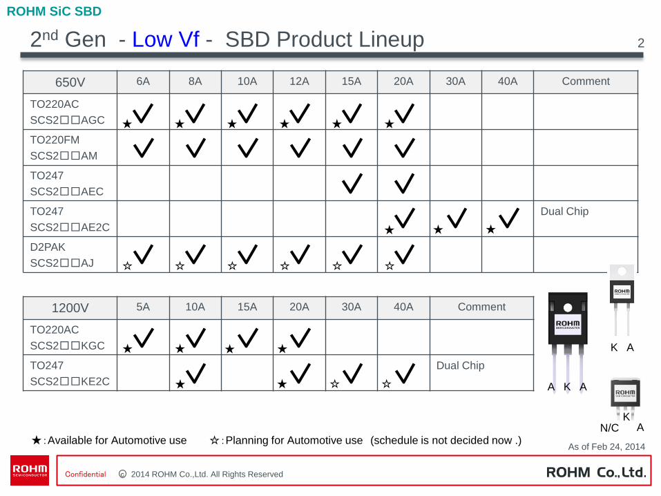
2nd Gen - Low Vf - SBD Product Lineup
ROHM SiC SBD
★:Available for Automotive use ☆:Planning for Automotive use (schedule is not decided now .)
K A
A K A
K A N/C
As of Feb 24, 2014
2
650V 6A 8A 10A 12A 15A 20A 30A 40A Comment
TO220AC
SCS2□□AGC
TO220FM
SCS2□□AM
TO247
SCS2□□AEC
TO247
SCS2□□AE2C
Dual Chip
D2PAK
SCS2□□AJ
★
1200V 5A 10A 15A 20A 30A 40A Comment
TO220AC
SCS2□□KGC
TO247
SCS2□□KE2C
Dual Chip
★ ★ ★ ★ ★
★
★ ★
★
★ ★
★ ★
★ ☆ ☆
☆ ☆ ☆ ☆ ☆ ☆
c 2014 ROHM Co.,Ltd. All Rights Reserved Confidential
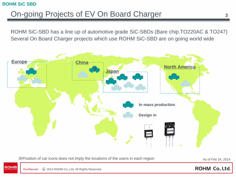
On-going Projects of EV On Board Charger 3
In mass production
Design in
?
Europe
Japan
China North America
※Position of car icons does not imply the locations of the users in each region
ROHM SiC-SBD has a line up of automotive grade SiC-SBDs (Bare chip,TO220AC & TO247)
Several On Board Charger projects which use ROHM SiC-SBD are on going world wide
ROHM SiC SBD
As of Feb 24, 2014

c 2014 ROHM Co.,Ltd. All Rights Reserved Confidential
2nd generation “low-VF” SiC-SBD
0.1~0.15V lower VF is achieved compared with 1G SBD
Forward characteristics (T=25˚C)
Forward characteristics (T=125˚C)
4
0123456789
10
0 0.5 1 1.5 2 2.5
Forward bias voltage (V)
Forw
ard
curr
ent
(A)
01
23
45
67
89
10
0 0.5 1 1.5 2 2.5
Forward bias voltage (V)
Forw
ard
curr
ent
(A)
ROHM
1st Gen SBD
ROHM
2nd Gen SBD ROHM
1st Gen SBD
ROHM
2nd Gen SBD
ROHM SiC SBD
c 2014 ROHM Co.,Ltd. All Rights Reserved Confidential
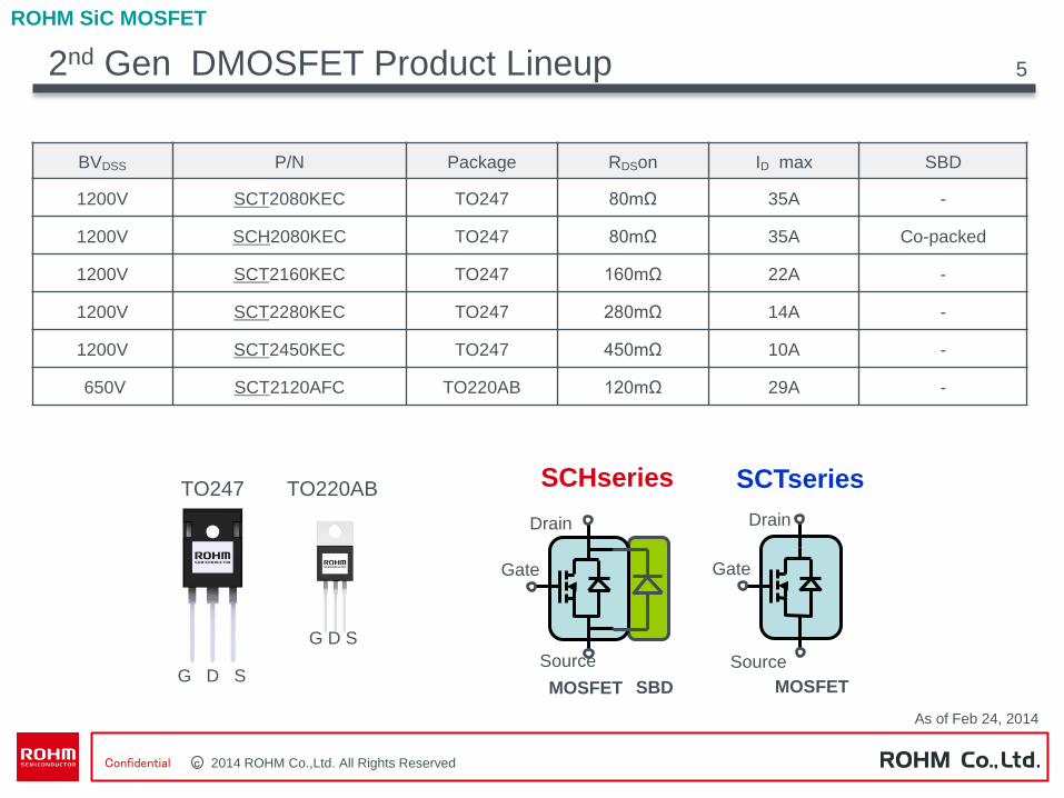
2nd Gen DMOSFET Product Lineup
ROHM SiC MOSFET
SCHseries
Drain
Gate
Source
SBD MOSFET
SCTseries
Drain
Gate
Source
MOSFET
TO247 TO220AB
G D S
G D S
As of Feb 24, 2014
5
BVDSS P/N Package RDSon ID max SBD
1200V SCT2080KEC TO247 80mΩ 35A -
1200V SCH2080KEC TO247 80mΩ 35A Co-packed
1200V SCT2160KEC TO247 160mΩ 22A -
1200V SCT2280KEC TO247 280mΩ 14A -
1200V SCT2450KEC TO247 450mΩ 10A -
650V SCT2120AFC TO220AB 120mΩ 29A -
c 2014 ROHM Co.,Ltd. All Rights Reserved Confidential
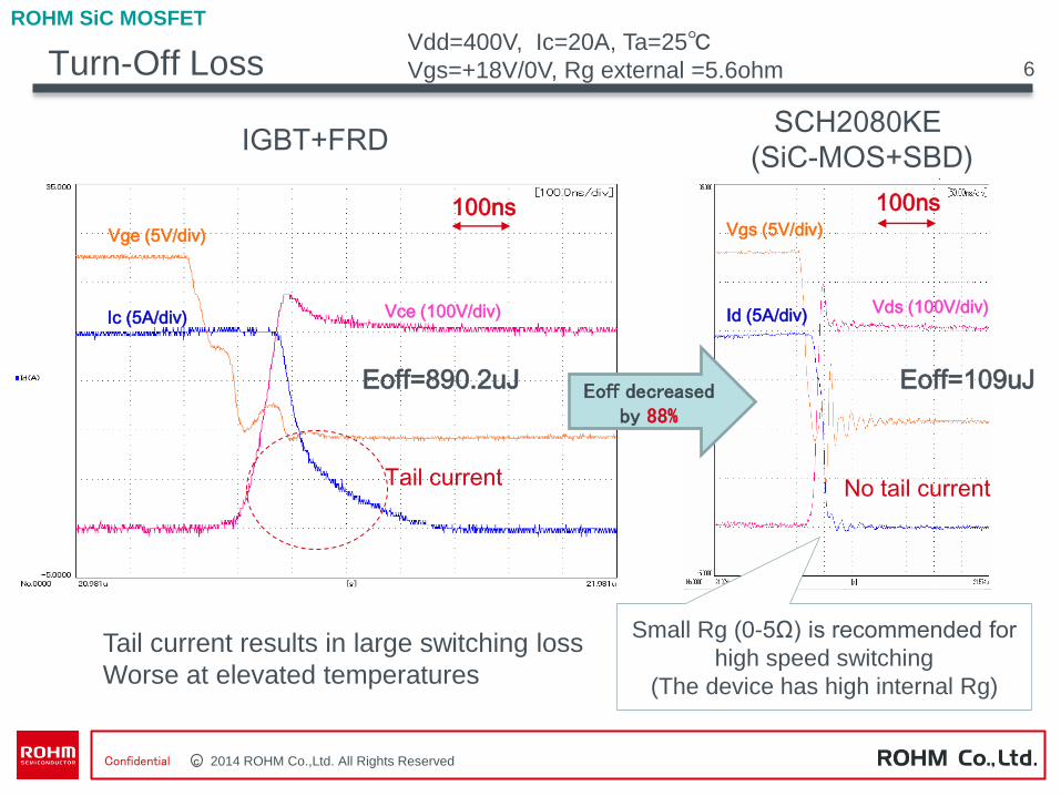
Turn-Off Loss
Eoff=890.2uJ
Ic (5A/div)
Vge (5V/div)
Vce (100V/div)
Tail current results in large switching loss
Worse at elevated temperatures
Eoff=109uJ
Id (5A/div)
Vgs (5V/div)
Vds (100V/div)
100ns
SCH2080KE
(SiC-MOS+SBD) IGBT+FRD
100ns
No tail current Tail current
6
ROHM SiC MOSFET
Eoff decreased by 88%
Small Rg (0-5Ω) is recommended for
high speed switching
(The device has high internal Rg)
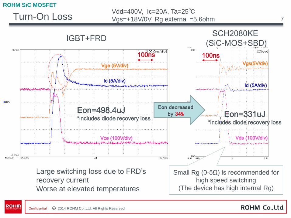
Vdd=400V, Ic=20A, Ta=25℃
Vgs=+18V/0V, Rg external =5.6ohm
c 2014 ROHM Co.,Ltd. All Rights Reserved Confidential
Eon=498.4uJ*includes diode recovery loss
Ic (5A/div)
Vge (5V/div)
Vce (100V/div)
Id (5A/div)
Vgs(5V/div)
Vds (100V/div)
100ns100ns
SiC-MOSFET+SBD(SCH2080KE)
Si-IGBT+FRD
Eon=331uJ*includes diode recovery loss
Turn-On Loss
SCH2080KE
(SiC-MOS+SBD)
Eon decreased by 34%
Large switching loss due to FRD’s
recovery current
Worse at elevated temperatures
Small Rg (0-5Ω) is recommended for
high speed switching
(The device has high internal Rg)
Vdd=400V, Ic=20A, Ta=25℃
Vgs=+18V/0V, Rg external =5.6ohm
ROHM SiC MOSFET
7
IGBT+FRD

c 2014 ROHM Co.,Ltd. All Rights Reserved Confidential
Characteristics of Body Di of SiC-MOSFET
-5
0
5
10
15
20
25
0 50 100 150 200 250 300 350 400
time (ns)If (
A)
SCH2080KE
SCT2080KE
Vdd=400V
Ta=25℃
-30
-25
-20
-15
-10
-5
0
-10 -8 -6 -4 -2 0
Vgs=0V
Vgs=2V
Vgs=4V
Vgs=6V
Ta=25ºC
Pulsed
Vgs=10V
Vgs=14V
Vgs=18V
Dra
in C
urr
en
t : I D
[A
]
Drain - Source Voltage : VDS [V]
Vd- Id Characteristics (reverse direction) Reverse recovery waveform
MOS+SBD
MOS (body-diode)
As a wide-bandgap semiconductor,
Vf of body Di is high. But with its
gate turn-on, it gets much lower Vf
by reverse conduction
ROHM SiC MOSFET
Unlike Si MOSFET, SiC MOSFET
has a body Di with a quite small Trr
8

c 2014 ROHM Co.,Ltd. All Rights Reserved Confidential
SiC-MOSFETs for Auxiliary Power Supplies
ROHM SiC MOSFET
9
BVDSS RDSon ID max (*Tentative) P/N Package Remarks
1200V 80mΩ 35A SCT2080KEC
TO247 MP 1200V 160mΩ 22A SCT2160KEC
1200V 280mΩ 14A SCT2280KEC
1200V 450mΩ 10A SCT2450KEC
1700V* 750mΩ*
~2.8Ω* 5.5A*~2A* - - Under Study
Inverter Converter
Converter
AC
100V
~400V Output
DC 5V~48V
(for system, etc,)
Block diagram of Inverter (Power supply, welding machine, etc,,)with auxiliary power supply
Fly back Forward
Sub
Main circuit
Circuit example
For auxiliary power supply circuit,
SiC-MOSFETs are better alternatives to
Si-MOSFETs with +1000V VDSS.
Etc…
In case of
AC400V input
Line up
These are target spec, so they might be changed or stopped without notice.
1>Downsize / reduction of heatsink
Due to lower power loss, SiC-MOSFETs reduce the
size of heatsinks.
than Si-MOS.
2>Better electrical performance
Lower Qg and capacitance of SiC –MOSFET than Si-
MOSFET brings better electrical performance
As of Feb 24, 2014
c 2014 ROHM Co.,Ltd. All Rights Reserved Confidential
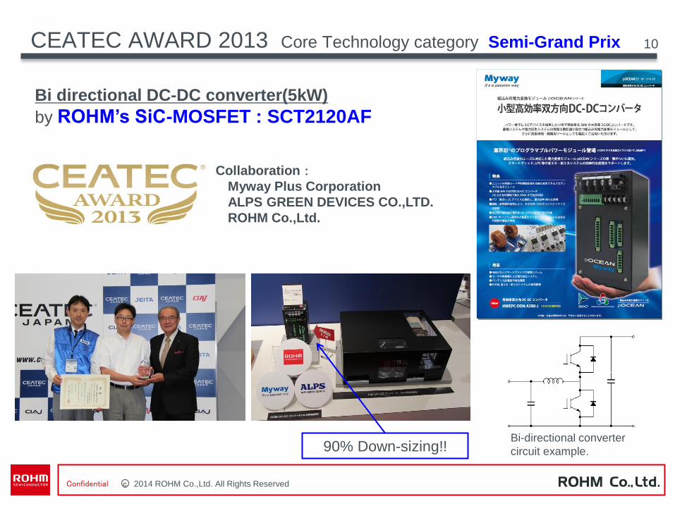
CEATEC AWARD 2013 Core Technology category Semi-Grand Prix 10
Collaboration:
Myway Plus Corporation
ALPS GREEN DEVICES CO.,LTD.
ROHM Co.,Ltd.
Bi directional DC-DC converter(5kW)
by ROHM’s SiC-MOSFET : SCT2120AF
90% Down-sizing!! Bi-directional converter
circuit example.

c 2014 ROHM Co.,Ltd. All Rights Reserved Confidential
11 Reliability of SiC MOSFET
JEDEC qualification test does not cover SiC specific items such as Body diode
conduction - ROHM’s SiC-MOSFET’s have no reliability issue
Reliability of SiC MOSFET
TEST Condition SCT2080KE
HTGB Vgs=22V Ta=150℃
⊿Vth=+0.2~0.3V (1000h, n=1000)
Gate-Oxide
CCS-TDDB Ig=0.5~5mA/cm2 Qbd=15~20C/cm2
(Equivalent to Si-MOS)
Body-diode Conduction
Is=8A, Ta=25℃ Without any change (1000h, Pn=0/20)
Cosmic-Ray Ruggedness
(SEB)
Vds=1200V 4000m: 10FIT
0m: 0.5FIT
c 2014 ROHM Co.,Ltd. All Rights Reserved Confidential
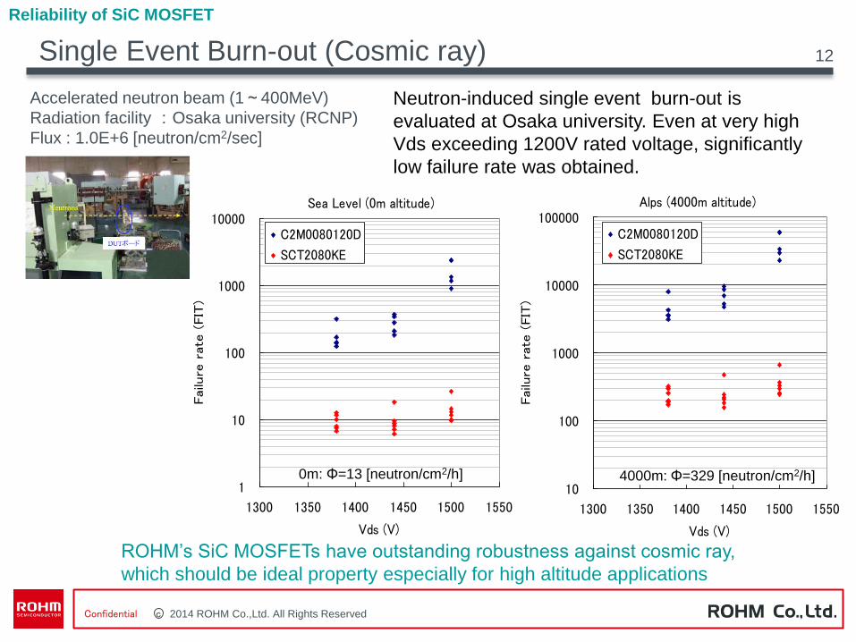
Single Event Burn-out (Cosmic ray)
Neutron-induced single event burn-out is
evaluated at Osaka university. Even at very high
Vds exceeding 1200V rated voltage, significantly
low failure rate was obtained.
Accelerated neutron beam (1~400MeV)
Radiation facility :Osaka university (RCNP)
Flux : 1.0E+6 [neutron/cm2/sec]
ROHM’s SiC MOSFETs have outstanding robustness against cosmic ray,
which should be ideal property especially for high altitude applications
Sea Level (0m altitude)
1
10
100
1000
10000
1300 1350 1400 1450 1500 1550
Vds (V)
Failu
re r
ate
(FIT
)
C2M0080120D
SCT2080KE
Alps (4000m altitude)
10
100
1000
10000
100000
1300 1350 1400 1450 1500 1550
Vds (V)Failu
re r
ate
(FIT
)
C2M0080120D
SCT2080KE
0m: Φ=13 [neutron/cm2/h] 4000m: Φ=329 [neutron/cm2/h]
Reliability of SiC MOSFET
12
c 2014 ROHM Co.,Ltd. All Rights Reserved Confidential
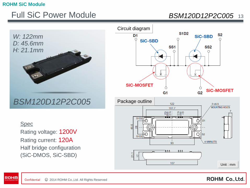
Full SiC Power Module
ROHM SiC Module
13
Package outline
BSM120D12P2C005
Spec
Rating voltage: 1200V
Rating current: 120A
Half bridge configuration
(SiC-DMOS, SiC-SBD)
Circuit diagram
BSM120D12P2C005
W: 122mm D: 45.6mm H: 21.1mm
BSM120D12P2C005
Unit : mm
c 2013 ROHM Co.,Ltd. All Rights Reserved Confidential
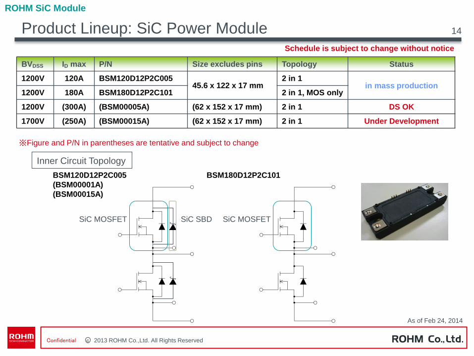
BVDSS ID max P/N Size excludes pins Topology Status
1200V 120A BSM120D12P2C005 45.6 x 122 x 17 mm
2 in 1 in mass production
1200V 180A BSM180D12P2C101 2 in 1, MOS only
1200V (300A) (BSM00005A) (62 x 152 x 17 mm) 2 in 1 DS OK
1700V (250A) (BSM00015A) (62 x 152 x 17 mm) 2 in 1 Under Development
Inner Circuit Topology
BSM120D12P2C005
(BSM00001A)
(BSM00015A)
BSM180D12P2C101
※Figure and P/N in parentheses are tentative and subject to change
SiC MOSFET SiC SBD SiC MOSFET
Schedule is subject to change without notice
As of Feb 24, 2014
Product Lineup: SiC Power Module
ROHM SiC Module
14
c 2014 ROHM Co.,Ltd. All Rights Reserved Confidential
Thank you !
15