oak ridge national laboratory sic/sic composites
TRANSCRIPT
ORNL/TM-2018/842
Oak Ridge National Laboratory SiC/SiC Composites Technology Gap Analysis for Molten Salt Reactors
Josina W. Geringer Takaaki Koyanagi Yoonjo Lee Yutai Katoh June 2018
Approved for public release. Distribution is unlimited.
DOCUMENT AVAILABILITY
Reports produced after January 1, 1996, are generally available free via US Department of Energy (DOE) SciTech Connect. Website www.osti.gov Reports produced before January 1, 1996, may be purchased by members of the public from the following source: National Technical Information Service 5285 Port Royal Road Springfield, VA 22161 Telephone 703-605-6000 (1-800-553-6847) TDD 703-487-4639 Fax 703-605-6900 E-mail [email protected] Website http://classic.ntis.gov/ Reports are available to DOE employees, DOE contractors, Energy Technology Data Exchange representatives, and International Nuclear Information System representatives from the following source: Office of Scientific and Technical Information PO Box 62 Oak Ridge, TN 37831 Telephone 865-576-8401 Fax 865-576-5728 E-mail [email protected] Website http://www.osti.gov/contact.html
This report was prepared as an account of work sponsored by an agency of the United States Government. Neither the United States Government nor any agency thereof, nor any of their employees, makes any warranty, express or implied, or assumes any legal liability or responsibility for the accuracy, completeness, or usefulness of any information, apparatus, product, or process disclosed, or represents that its use would not infringe privately owned rights. Reference herein to any specific commercial product, process, or service by trade name, trademark, manufacturer, or otherwise, does not necessarily constitute or imply its endorsement, recommendation, or favoring by the United States Government or any agency thereof. The views and opinions of authors expressed herein do not necessarily state or reflect those of the United States Government or any agency thereof.
ORNL/TM-2018/842
Material Science and Technology Division
SIC/SIC COMPOSITES TECHNOLOGY GAP ANALYSIS
FOR MOLTEN SALT REACTORS
Authors:
Josina W. Geringer
Takaaki Koyanagi
Yoonjo Lee
Yutai Katoh
Date Published:
June 2018
Prepared by
OAK RIDGE NATIONAL LABORATORY
Oak Ridge, TN 37831-6283
managed by
UT-BATTELLE, LLC
for the
US DEPARTMENT OF ENERGY
under contract DE-AC05-00OR22725

iii
CONTENTS
EXECUTIVE SUMMARY ....................................................................................................................... viii ACKNOWLEDGMENTS .......................................................................................................................... xii 1. INTRODUCTION ................................................................................................................................ 1 2. DESIGN METHODOLOGY ................................................................................................................ 2
2.1 TYPES OF REACTORS AND DESIGN MATURITY ............................................................. 2 2.2 TYPICAL APPLICATIONS FOR SIC COMPONENTS, FUNCTION, GENERAL
REQUIREMENTS, AND REACTOR LOCATION .................................................................. 5 2.3 TYPICAL TEMPERATURES, FLUENCE, AND LOADING CONDITIONS ...................... 11 2.4 CODE DEVELOPMENT ACTIVITIES FOR SiC STRUCTURAL MATERIALS ................ 13 2.5 LICENSING ASPECTS ........................................................................................................... 16 2.6 THE TECHNOLOGY GAPS IN THE DESIGN METHODOLOGY ...................................... 17
3. MATERIALS AND MANUFACTURING ........................................................................................ 18 3.1 COMPOSITES: FIBERS, MATRICES, AND INTERFACE .................................................. 18
3.1.1 Fiber ............................................................................................................................. 18 3.1.2 Matrix ........................................................................................................................... 19 3.1.3 Interface ....................................................................................................................... 20
3.2 JOINING AND INTEGRATION TECHNOLOGIES .............................................................. 20 3.2.1 Joint Processing ........................................................................................................... 21 3.2.2 Assembly Technologies ............................................................................................... 21 3.2.3 Properties of the Joints ................................................................................................. 22
3.3 FABRICATION OF SiC COMPONENTS ............................................................................... 23 3.4 TECHNOLOGY GAPS FOR SiC/SiC MATERIALS AND MANUFACTURING ................ 27
4. PROPERTIES AND RADIATION EFFECTS .................................................................................. 28 4.1 IRRADIATION EFFECTS ....................................................................................................... 28
4.1.1 Dimensional Stability ................................................................................................... 28 4.1.2 Mechanical Properties .................................................................................................. 29 4.1.3 Thermal Properties ....................................................................................................... 30
4.2 MICRO-CRACKING RELATED ISSUES .............................................................................. 31 4.3 TECHNOLOGY GAPS IN THE PHYSICAL/MECHANICAL PROPERTIES AND
RADIATION EFFECTS ........................................................................................................... 32 5. CHEMICAL COMPATIBILITY ....................................................................................................... 33
5.1 MODES OF SiC CORROSION ............................................................................................... 33 5.1.2 SiC interactions with moisture-based impurities, tritium, and gaseous fission
products ........................................................................................................................ 36 5.2 THERMOPHYSICAL PROPERTIES OF SALTS .................................................................. 40
5.2.1 Physical Chemistry of Candidate Coolant Salts ........................................................... 40 5.3 THE TECHNOLOGY GAPS FOR CHEMICAL COMPATIBILITy ...................................... 45
6. CONCLUSION AND PATH FORWARD ......................................................................................... 46 7. REFERENCES ................................................................................................................................... 48
7.1 SECTION 1 ............................................................................................................................... 48 7.2 SECTION 2 ............................................................................................................................... 48 7.3 SECTION 3 ............................................................................................................................... 49 7.4 SECTION 4 ............................................................................................................................... 51 7.5 SECTION 5 ............................................................................................................................... 52
iv
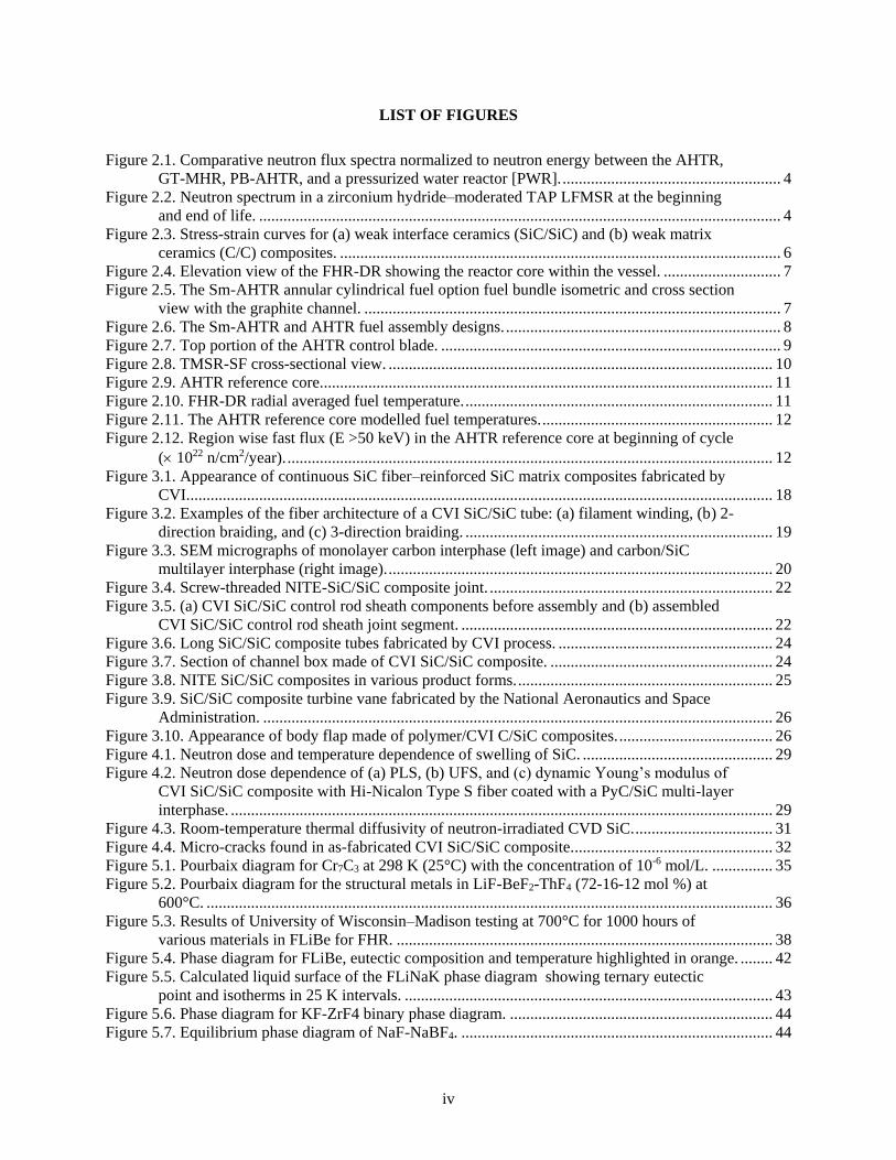
LIST OF FIGURES
Figure 2.1. Comparative neutron flux spectra normalized to neutron energy between the AHTR,
GT-MHR, PB-AHTR, and a pressurized water reactor [PWR]. ...................................................... 4 Figure 2.2. Neutron spectrum in a zirconium hydride–moderated TAP LFMSR at the beginning
and end of life. ................................................................................................................................. 4 Figure 2.3. Stress-strain curves for (a) weak interface ceramics (SiC/SiC) and (b) weak matrix
ceramics (C/C) composites. ............................................................................................................. 6 Figure 2.4. Elevation view of the FHR-DR showing the reactor core within the vessel. ............................. 7 Figure 2.5. The Sm-AHTR annular cylindrical fuel option fuel bundle isometric and cross section
view with the graphite channel. ....................................................................................................... 7 Figure 2.6. The Sm-AHTR and AHTR fuel assembly designs. .................................................................... 8 Figure 2.7. Top portion of the AHTR control blade. .................................................................................... 9 Figure 2.8. TMSR-SF cross-sectional view. ............................................................................................... 10 Figure 2.9. AHTR reference core. ............................................................................................................... 11 Figure 2.10. FHR-DR radial averaged fuel temperature. ............................................................................ 11 Figure 2.11. The AHTR reference core modelled fuel temperatures. ......................................................... 12 Figure 2.12. Region wise fast flux (E >50 keV) in the AHTR reference core at beginning of cycle
( 1022 n/cm2/year). ........................................................................................................................ 12 Figure 3.1. Appearance of continuous SiC fiber–reinforced SiC matrix composites fabricated by
CVI................................................................................................................................................. 18 Figure 3.2. Examples of the fiber architecture of a CVI SiC/SiC tube: (a) filament winding, (b) 2-
direction braiding, and (c) 3-direction braiding. ............................................................................ 19 Figure 3.3. SEM micrographs of monolayer carbon interphase (left image) and carbon/SiC
multilayer interphase (right image). ............................................................................................... 20 Figure 3.4. Screw-threaded NITE-SiC/SiC composite joint. ...................................................................... 22 Figure 3.5. (a) CVI SiC/SiC control rod sheath components before assembly and (b) assembled
CVI SiC/SiC control rod sheath joint segment. ............................................................................. 22 Figure 3.6. Long SiC/SiC composite tubes fabricated by CVI process. ..................................................... 24 Figure 3.7. Section of channel box made of CVI SiC/SiC composite. ....................................................... 24 Figure 3.8. NITE SiC/SiC composites in various product forms. ............................................................... 25 Figure 3.9. SiC/SiC composite turbine vane fabricated by the National Aeronautics and Space
Administration. .............................................................................................................................. 26 Figure 3.10. Appearance of body flap made of polymer/CVI C/SiC composites. ...................................... 26 Figure 4.1. Neutron dose and temperature dependence of swelling of SiC. ............................................... 29 Figure 4.2. Neutron dose dependence of (a) PLS, (b) UFS, and (c) dynamic Young’s modulus of
CVI SiC/SiC composite with Hi-Nicalon Type S fiber coated with a PyC/SiC multi-layer
interphase. ...................................................................................................................................... 29 Figure 4.3. Room-temperature thermal diffusivity of neutron-irradiated CVD SiC. .................................. 31 Figure 4.4. Micro-cracks found in as-fabricated CVI SiC/SiC composite. ................................................. 32 Figure 5.1. Pourbaix diagram for Cr7C3 at 298 K (25°C) with the concentration of 10-6 mol/L. ............... 35 Figure 5.2. Pourbaix diagram for the structural metals in LiF-BeF2-ThF4 (72-16-12 mol %) at
600°C. ............................................................................................................................................ 36 Figure 5.3. Results of University of Wisconsin–Madison testing at 700°C for 1000 hours of
various materials in FLiBe for FHR. ............................................................................................. 38 Figure 5.4. Phase diagram for FLiBe, eutectic composition and temperature highlighted in orange. ........ 42 Figure 5.5. Calculated liquid surface of the FLiNaK phase diagram showing ternary eutectic
point and isotherms in 25 K intervals. ........................................................................................... 43 Figure 5.6. Phase diagram for KF-ZrF4 binary phase diagram. ................................................................. 44 Figure 5.7. Equilibrium phase diagram of NaF-NaBF4. ............................................................................. 44
v
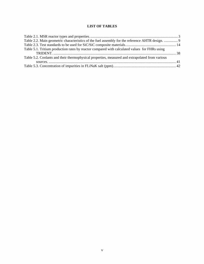
LIST OF TABLES
Table 2.1. MSR reactor types and properties. ............................................................................................... 3 Table 2.2. Main geometric characteristics of the fuel assembly for the reference AHTR design. ............... 9 Table 2.3. Test standards to be used for SiC/SiC composite materials. ...................................................... 14 Table 5.1. Tritium production rates by reactor compared with calculated values for FHRs using
TRIDENT. ..................................................................................................................................... 38 Table 5.2. Coolants and their thermophysical properties, measured and extrapolated from various
sources. .......................................................................................................................................... 41 Table 5.3. Concentration of impurities in FLiNaK salt (ppm). ................................................................... 42
vi
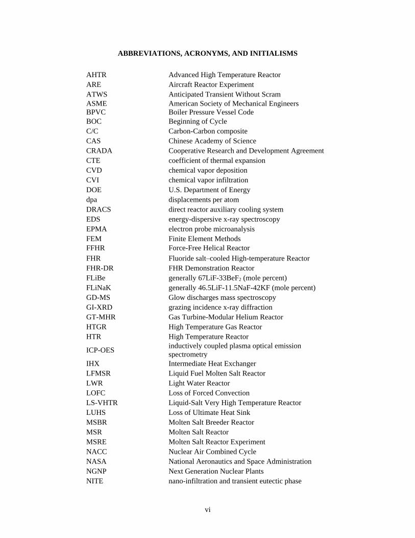
ABBREVIATIONS, ACRONYMS, AND INITIALISMS
AHTR Advanced High Temperature Reactor
ARE Aircraft Reactor Experiment
ATWS Anticipated Transient Without Scram
ASME
BPVC
American Society of Mechanical Engineers
Boiler Pressure Vessel Code
BOC Beginning of Cycle
C/C Carbon-Carbon composite
CAS Chinese Academy of Science
CRADA Cooperative Research and Development Agreement
CTE coefficient of thermal expansion
CVD chemical vapor deposition
CVI chemical vapor infiltration
DOE U.S. Department of Energy
dpa displacements per atom
DRACS direct reactor auxiliary cooling system
EDS energy-dispersive x-ray spectroscopy
EPMA electron probe microanalysis
FEM Finite Element Methods
FFHR Force-Free Helical Reactor
FHR Fluoride salt–cooled High-temperature Reactor
FHR-DR FHR Demonstration Reactor
FLiBe generally 67LiF-33BeF2 (mole percent)
FLiNaK generally 46.5LiF-11.5NaF-42KF (mole percent)
GD-MS Glow discharges mass spectroscopy
GI-XRD grazing incidence x-ray diffraction
GT-MHR Gas Turbine-Modular Helium Reactor
HTGR High Temperature Gas Reactor
HTR High Temperature Reactor
ICP-OES inductively coupled plasma optical emission
spectrometry
IHX Intermediate Heat Exchanger
LFMSR Liquid Fuel Molten Salt Reactor
LWR Light Water Reactor
LOFC Loss of Forced Convection
LS-VHTR Liquid-Salt Very High Temperature Reactor
LUHS Loss of Ultimate Heat Sink
MSBR Molten Salt Breeder Reactor
MSR Molten Salt Reactor
MSRE Molten Salt Reactor Experiment
NACC Nuclear Air Combined Cycle
NASA National Aeronautics and Space Administration
NGNP Next Generation Nuclear Plants
NITE nano-infiltration and transient eutectic phase
vii
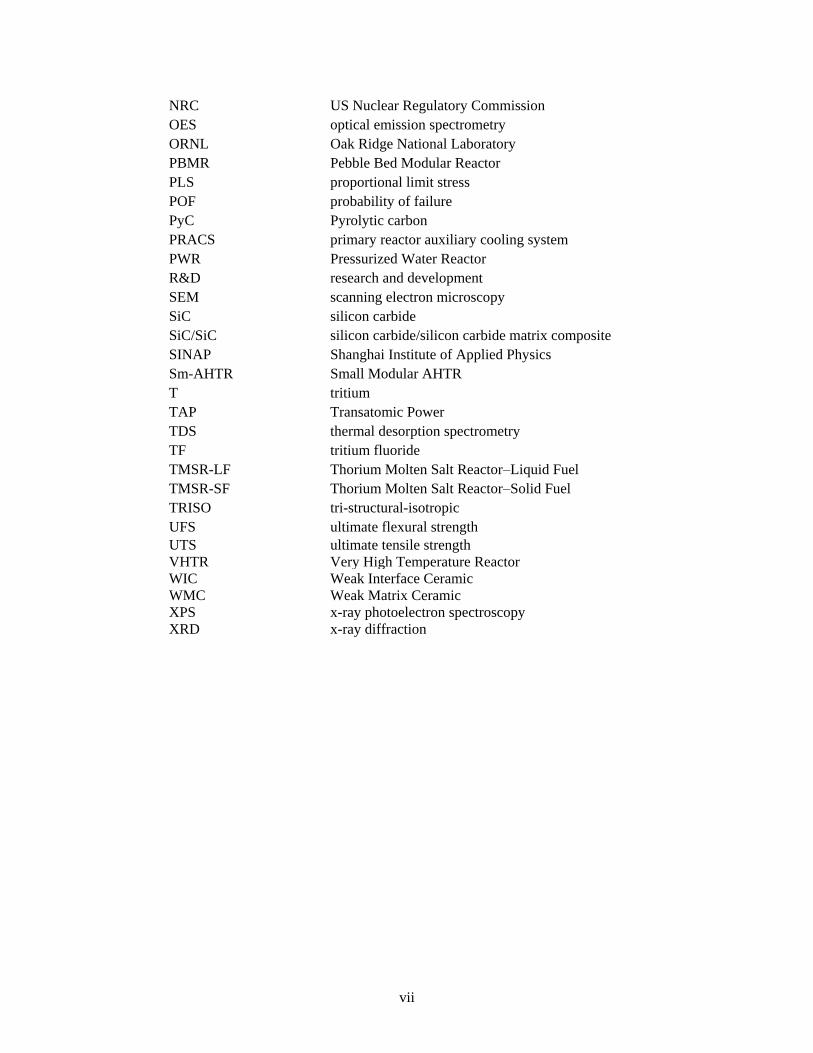
NRC US Nuclear Regulatory Commission
OES optical emission spectrometry
ORNL Oak Ridge National Laboratory
PBMR Pebble Bed Modular Reactor
PLS proportional limit stress
POF probability of failure
PyC Pyrolytic carbon
PRACS primary reactor auxiliary cooling system
PWR Pressurized Water Reactor
R&D research and development
SEM scanning electron microscopy
SiC silicon carbide
SiC/SiC silicon carbide/silicon carbide matrix composite
SINAP Shanghai Institute of Applied Physics
Sm-AHTR Small Modular AHTR
T tritium
TAP Transatomic Power
TDS thermal desorption spectrometry
TF tritium fluoride
TMSR-LF Thorium Molten Salt Reactor–Liquid Fuel
TMSR-SF Thorium Molten Salt Reactor–Solid Fuel
TRISO tri-structural-isotropic
UFS ultimate flexural strength
UTS ultimate tensile strength
VHTR Very High Temperature Reactor
WIC Weak Interface Ceramic
WMC Weak Matrix Ceramic
XPS x-ray photoelectron spectroscopy
XRD x-ray diffraction

viii
EXECUTIVE SUMMARY
The purpose of this report is to identify the research and development (R&D) gaps for potential applications
of silicon carbide/silicon carbide matrix (SiC/SiC) composite components for Generation IV Molten Salt
Reactors (MSRs).
There are several different MSR concepts, which can be grouped into two classes: those with solid fuel and
those with liquid fuel. The Fluoride salt-cooled High-temperature Reactor (FHR), with solid fuel and
molten salt coolant, and the Liquid Fuel MSR (LFMSR), a reactor wherein the fuel is dissolved into the
molten salt, are the example concepts in these two classes, respectively. The primary candidate coolant for
FHRs is a molten fluoride salt; an LFMSR assumes the use of either fluoride or chloride salt mixtures. As
a Generation IV reactor concept, MSRs shall demonstrate sustainability (mainly waste manageability),
proliferation-resistant secure nuclear systems, competitive cost of energy, and safety and reliability,
including acceptable performance of key materials for licensing.
The FHR concept is considered technologically more mature than other MSR concepts. FHRs typically
have a thermal neutron spectrum, whereas other MSRs have been designed with epithermal or fast neutron
spectra. Core outlet temperatures are in general below 750°C with pressures near atmospheric conditions.
The FHRs feature high-temperature solid fuels, passive safety features such as auxiliary cooling systems
like those in sodium fast reactors, intermediate heat exchangers, and salt freeze tanks.
SiC/SiC composites are particularly suitable for certain components in these systems because they have
outstanding high-temperature capability and tolerance against neutron irradiation. Moreover, MSRs in
general will greatly benefit from the use of SiC/SiC composites for components that need to withstand harsh
operating environments combining some, or all, of the characteristics of high temperature, high neutron
flux, high lifetime neutron fluence, and direct contact with molten salt, regardless of reactor concepts or
designs. The materials and application technologies surrounding SiC/SiC composites are rapidly advancing
as the material find niche, yet growing, applications—mainly outside the field of nuclear energy. However,
significant R&D is still needed before SiC/SiC composite materials and their application technology
become ready for the qualification of designs employing components made of these materials.
The purpose of this study is to identify the remaining technology gaps for SiC/SiC composite materials and
to evaluate their readiness for use in MSRs with regard to aspects concerning the maturity of design methods
and rules; the materials and manufacturing techniques, with a focus on limitations regarding scalability and
component sizes; material performance, in terms of mechanical and thermal property data; and chemical
interactions and compatibility.
Design Methodology
SiC/SiC composites have been identified as suitable materials for several MSR core components, which
include, but are not limited to, the reactor control rod and fuel assembly supports, tie rod supports, core
support plates, guide tubes for instrumentation sleeves, and the core barrel.
In general, components for fuel assemblies and reactivity control systems need to be evaluated for in-service
conditions. Factors of critical concern include mechanical distortion due to radiation-induced warping,
surface erosion and mechanical debonding.
For FHRs, external loads, due to flows, pressure differentials, buoyancy etc., are expected to be different
than High Temperature Gas Reactor (HTGR) loads and will have to be considered during design to show
that the structures maintain adequate levels of integrity through the design life. Effects like thermal striping
and flow induced vibration are likely to be important in FHR designs while less significant to HTGR designs
(because the salt is a better heat transfer material and more dense than helium). The ASME code would
ix
need to be reviewed to ensure that it makes sufficient provision to address these effects. It also need to be
compared with load conditions expected for LFMSRs.
The design rules for high-temperature reactor composite core components are near completion for first
publication in the ASME Boiler and Pressure Vessel Code Section III Div. 5 code. It makes provisions for
HTGRs as well as MSRs, specifically FHRs. Future compatibility assessment for LFMSRs may be required
as the different front runner technologies advance.
The design rules need to be validated by the US Nuclear Regulatory Commission (NRC) before it can
endorse the code for licensing purposes. Due to the lack of a demonstration reactor and a need to validate
the rules, it is required to develop a technical basis document that supports the conditions described in the
code with benchmarking data.
The establishment of standard material specifications, test methods, and practices is an important part of
the design rules development. The currently available test standards, are missing some of the important
elements required for qualifying SiC/SiC component designs for MSRs, in particular, in the area of test
methods for elevated temperature properties. In addition, many test standards developed in ASTM
Committee C28 on Advanced Ceramics are missing the section on precision and bias based on the round-
robin testing campaigns.
Current experience with SiC/SiC composites use in jet engines and the ongoing development of SiC/SiC
technologies for accident-tolerant light water reactor (LWR) fuels are expected to advance the technological
maturity of SiC/SiC composites as structural components of nuclear reactors. This is of critical importance
because SiC/SiC composites have much less structural application experience and fewer data compared
with metals. Interactions with these developments are essential in advancing the design methodology
related to SiC/SiC for MSRs.
Materials and Manufacturing
SiC materials of interest for nuclear structural applications are mostly continuous fiber-reinforced ceramic
matrix composites, which consist of SiC fiber, SiC matrix, and the fiber-matrix interphase. Nuclear-grade
composites consist specifically of fully crystalline and stoichiometric SiC fibers and matrices and use a
carbon interphase. Such composites are available through the chemical vapor infiltration (CVI) and nano-
infiltration and transient eutectic-phase (NITE) processing routes.
Fabrication of large and complex-shape components made of nuclear-grade SiC/SiC composites will be
necessary for MSR applications. Although processing elements—such as the fiber preforming process,
matrix densification, and joining/integration technologies—are reasonably mature, demonstration of the
component fabrication and performance against the design requirements will be required.
Assembly technology for both CVI and NITE SiC/SiC composites exists, and it enables the fabrication of
complex components made without using exotic joining materials. Testing was performed on the strength
of SiC-to-SiC joints, and retention of joint strength following irradiation was demonstrated for a SiC-based
bonding layer. However, because joints are often the weakest links in components and systems, they will
have to be further evaluated.
Fabrication technologies for dissimilar joints were demonstrated for SiC joined to limited metallic
materials, including aluminum and steels. Such technology development often involves significant
challenges. Common hurdles at elevated temperatures are undesirable reactions and residual stresses.
Further development of joining technology will be required if joining SiC to dissimilar materials is required
for MSR applications.
x
Securing gas-tightness proved to be a significant challenge in the development of LWR fuel cladding, for
both as-fabricated SiC/SiC composite tubes and end-plug joints. If hermeticity is required for SiC/SiC
components for MSRs, manufacturing technologies to ensure it need to be fully developed and
demonstrated for the composites and the integration elements. For MSRs, particularly the liquid fuel
concepts, molten salt ingress into open pores and cracks exposed to the outer surfaces may present an
important concern. Manufacturing of SiC/SiC composite components will have to address such concerns.
Properties and Radiation Effects
The design database for key physical, thermal, and mechanical properties is rapidly being augmented for
CVI SiC/SiC composites as the R&D toward LWR applications progresses. However, a significant
knowledge gap will remain, primarily in the areas related to the high-temperature operation of MSRs and
the molten salt–specific operating environment, even after the ongoing LWR accident-tolerant fuel
technology development effort successfully accomplishes its mission.
The primary gap in the thermo-mechanical properties and performance include those related to the
component service life, including creep, fatigue, and environmentally assisted mechanical degradation. In
particular, stress-corrosion cracking and the resultant slow crack growth could be a critical design-limiting
issue. Moreover, understanding of the effects of repetitive motion, such as fatigue and fretting, in the salt
environment needs to be established because they are important for MSR applications.
The other major gap in this category is an understanding of irradiation effects on mechanical properties.
The effects of neutron irradiation on mechanical properties can be a significant design-limiting issue for
SiC/SiC components when the expected neutron dose is very high. In fact, recent studies indicate significant
strength degradation after ~70 dpa irradiation in a 500–800°C temperature range because of the radiation
instability of Hi-Nicalon Type S fibers and the carbon interphase.
For improved high-dose irradiation tolerance, true SiC fiber (free of significant second phases or off-
stoichiometry) and improved interphase materials or designs will be needed. Although such developments
are currently being undertaken or proposed, none of them is ready for industrial-scale production. SiC/SiC
composites made of improved radiation resistance constituents are anticipated to be resistant to very high-
dose irradiation, potentially offering a material solution for the fast spectrum MSR concepts where the core
materials receive very high doses of neutrons, whereas the present generation SiC/SiC composites may
present adequate radiation stability for thermal spectrum MSR concepts where the neutron dose to core
materials will be moderate.
Chemical Compatibility
SiC components will be exposed to diverse chemical environments. In FHRs, the environment will include
metals, carbon, impurities, and transmutants in a molten fluoride salt. A preferred salt for the FHR’s primary
coolant system is 67LiF-33BeF2 (FLiBe), which is also a candidate for the intermediate loop system, along
with 46.5LiF-11.5NaF-42KF (FLiNaK). Suspected incompatibility with chloride salts needs to be verified.
The corrosion of SiC in molten fluoride salts is driven by thermal gradients and salt impurities. SiC exhibits
wettability and chemical reactivity with liquid metals but is generally stable in molten fluoride salts so long
as the salt purity is maintained. Very little is known about thermal gradient–driven corrosion which is likely
to sustain corrosion. The corrosion of SiC in molten fluoride salt depends directly on the redox condition
of the salt and the various methods used to mitigate impurities and tritium. The corrosion of SiC in FLiBe
and FLiNaK has been studied directly in very few instances, whereas the corrosion of carbon and heat
exchanger alloys in molten fluoride salts and nitrate salts is more well known. SiC/SiC components are
proposed in areas of higher neutron fluxes and should be considered permanent installations in the reactor
core. Replacement would be costly and could require prolonged shutdown periods.
xi
Tritium is a major issue for FHRs. Recent studies have modeled the tritium levels in FHRs and predict that
it will exceed those in heavy water reactors at equilibrium conditions. The corrosion behavior of SiC and
container alloys is directly related to the tritium capture and recovery systems. Hydrogen and its isotopes
are highly mobile in metals and possibly in SiC. Solubility of tritium and lattice diffusion behavior in
irradiated SiC should be studied in conjunction with the surface corrosion and microcracking.
Corrosion testing can be performed with static experiments in sealed capsules or dynamic loop experiments
(thermal or forced convection). Historically, most of the loop testing of alloys in molten fluoride salt
occurred at Oak Ridge National Laboratory in the 1970s and 1980s. There is not a lot of theoretical
development in this area of science, and much of the research is very much applied R&D. The static tests
have demonstrated their practicality, but they are prone to error; and oxygen leaks could cause a much
higher corrosion rate. Thermal and forced convection loop corrosion testing of SiC has not yet been
performed.
The corrosion resistance of SiC and variants in molten fluoride salts will depend on the redox condition of
the salt and tritium capture and salt purification methods. Measurements of equilibria and thermochemical
data are needed, and predictions of corrosion reactions, corrosion products, and kinetics to determine the
corrosion behavior of SiC in the molten fluoride salts FliBe and FliNaK. With thermochemical
measurements and thermodynamic calculations, the control/removal of impurities can then be validated by
experiment. Kinetic measurements and rate equations can then follow to develop predictive models.

xii
ACKNOWLEDGMENTS
Support for this research was provided by the US Department of Energy, Office of Nuclear Energy
(DOE-NE), Advanced Reactor Technologies program, for the completion of activity milestone M3NT-
18OR070502012. Oak Ridge National Laboratory is managed by UT-Battelle LLC under contract no.
DE-AC05-00OR22725 for the US Department of Energy.
The authors extend their appreciation to Dr. Lou Qualls, Dr. David Holcomb, Dr. Stephen Raiman, Dr.
Tim Burchell, Dr. Cristian Contescu, Dr. Steven Gonczy, Dr. Michael Jenkins, Dr. Lauren Garrison, and
Mr. Mark Mitchell for their input and technical review.
1
1. INTRODUCTION
The purpose of this report is to survey the literature and identify the key research and development (R&D)
gaps regarding the application of silicon carbide/silicon carbide matrix (SiC/SiC) composites for structural
components of a molten salt reactor (MSR). SiC/SiC materials of interest for nuclear structural applications
are mostly continuous fiber reinforced ceramics matrix composites, which consist of a SiC fiber (like High
Nicalon Type S, Tyranno SA3 and Sylramic), SiC matrix (like the chemical vapor infiltration (CVI) matrix
or the Nano-Infiltration and Transient Eutectic phase (NITE) matrix), and a carbon interface between the
fiber and matrix (such as the multilayer pyarolytic carbon (PyC)/SiC interfaces).
In general, there are distinct differentiations between two MSR technologies; the fluoride-cooled high-
temperature reactors (FHRs) with solid fuel and a “clean” (non-fuel) salt coolant, and the liquid fuel MSR
(LFMSR) in which the coolant also carries dissolved fissile material and fission products. Both reactor
technologies are considered in this report.
Historical feasibility issues identified for SiC/SiC components have included (1) corrosion of SiC in the
candidate liquid salts, (2) high-dose neutron radiation effects, (3) static fatigue failure of SiC/SiC, (4) long-
term radiation effects including irradiation creep and radiation-enhanced static fatigue, and (5) the
fabrication technology for the hermetic wall and sealing end caps [1]. As a result, recent SiC/SiC R&D
related to MSRs has focused on (1) thermodynamic analysis and experimental examination of SiC corrosion
in candidate liquid salts, (2) assessment of long-term mechanical integrity issues, and (3) assessment of
high-dose radiation effects relevant to the anticipated operating conditions.
Early MSR designs often used Hastelloy N (a nickel-based metal alloy) and graphite as the structural and
core components, respectively. Both Hastelloy and carbon-based materials have their own unique
challenges in the MSR environment. SiC/SiC composites are particularly suitable for certain in-core
mechanical structures because of their outstanding high temperature capability related to thermal
conductivity and mechanical strength and then its tolerance against neutron irradiation. Therefore, SiC/SiC
is a potential replacement for several reactor core components currently designed for Hastelloy N or even
carbon/carbon components. Additionally, the long-term corrosion effects on metal components such as
instrumentation, reactivity control, and reactor enclosure are still serious concerns for MSRs [2]. If SiC/SiC
can withstand salt exposure with limited corrosion, it has been proposed that SiC/SiC composites be used
as a coating or barrier to protect the metal components from the salt at high temperatures, which would be
advantageous for both FHR and LFMSR development. This report discusses the progress made on these
issues.
The purpose of this study is to investigate and identify the remaining technology gaps for SiC/SiC
composite materials and to evaluate the material readiness on aspects concerning the
• maturity of design methods and rules needed to design reactor core components
• materials and manufacturing constraints and techniques, with a focus on limitations regarding
scalability and component sizes
• material performance under irradiation and in corrosive environments, assessing mechanical and
thermal property data
• chemical interactions and compatibility
This report makes initial recommendations on a path to continue the development of SiC composites for
applications in FHR and MSR components.
2
2. DESIGN METHODOLOGY
2.1 TYPES OF REACTORS AND DESIGN MATURITY
Historically there were two iconic MSRs, the Aircraft Reactor Experiment (ARE) and the Molten Salt
Reactor Experiment (MSRE), both designed by Oak Ridge National Laboratory (ORNL) in the mid-1900s.
They operated for a total of 100 hours and 21,000 hours, respectively. Between the mid-century era and
today, the development strategy and motivation for the development of MSRs continues mostly as an
international effort and by private companies, but with added awareness of the increased safety benefits of
such systems and the growing demand for energy. Representative FHR concepts are the Liquid-Salt Very
High Temperature Reactor (LS-VHTR) or the earlier Advanced High Temperature Reactor (AHTR) during
its preconceptual phase.
There are more than the two main technologies, FHR and LFMSR, as defined in this report [3]; but the
scope discussed herein mostly concerns the two main technology groups, with an emphasis on FHRs.
Recently, the pebble-bed FHR has been of interest with Kairos Power, a US-based company that announced
plans to commercialize its FHR within the next decade. The Kairos FHR will be designed to harvest nuclear
heat in a Nuclear Air Combined Cycle (NACC) that uses a conventional natural gas turbine modified to
accept nuclear heat. This design can co-fire natural gas to meet peak power demands and supplement the
natural gas market. The FHR is cooled with clean molten fluoride salt, moderated by graphite, and uses
encapsulated fuel particles similarly to a high temperature gas-cooled reactor (HTGR). The FHR concept
is probably the nearer-term MSR option that focuses on demonstrating acceptable performance of key
materials for licensing [1,3,4]. Typical core structural materials in contact with the salt coolant include
graphite, SiC, and nickel-based alloys [2,5].
Various FHR technology concepts exist, such as the AHTR, the Small Modular AHTR (Sm-AHTR), the
Pebble Bed-AHTR (PB-AHTR) or “Mark 1” [6], and the Thorium Molten Salt Reactor Solid Fuel (TMSR-
SF). The Mark 1 concept was originally developed by University of California–Berkeley and is the basic
concept on which the forerunner for the most near-term US technology is based. The TMSR-SF is also a
pebble bed reactor, developed by SINAP in China; and similar to the TMSR-LF (which uses liquid fuel), it
has a three-stage development plan from simulator to demonstration [7].
In the other main MSR category, the LFMSR, the fuel is dissolved in the salt, which is circulated through
the primary heat transfer loop. Several thermal and fast spectrum LFMSR designs are being pursued
commercially. Some of the fast spectrum versions make the LFMSR promising for breeding or high-
conversion options. Development is largely driven by private investors (both US and non-US companies),
such as Terrestrial Energy (thermal burner using uranium) and Transatomic Power (hybrid burner using
uranium). Other companies developing LFMSRs include TerraPower (fast breeder using uranium),
ThorCon (thermal burner using thorium), Flibe Energy (thermal breeder using thorium), and Elysium
Industries (fast breeder using uranium). Several other design concepts are in development internationally,
such as the Moltex (UK), Seaborg Technologies (Denmark), and FuJi (Japan) [8-11].
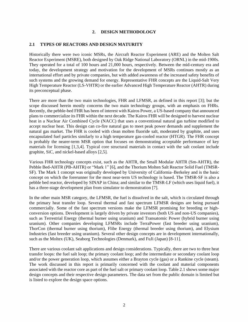
There are various coolant salt applications and design considerations. Typically, there are two to three heat
transfer loops: the fuel salt loop; the primary coolant loop; and the intermediate or secondary coolant loop
and/or the power generation loop, which assumes either a Brayton cycle (gas) or a Rankine cycle (steam).
The work discussed in this report is primarily concerned with the coolant and material components
associated with the reactor core as part of the fuel salt or primary coolant loop. Table 2.1 shows some major
design concepts and their respective design parameters. The data set from the public domain is limited but
is listed to explore the design space options.
3
Table 2.1. MSR reactor types and properties.
Design FHR-DR AHTR Sm-AHTR Mark 1 TMSR-SF1 TMSR-LF1 IMSR TAP
Design authority ORNL ORNL ORNL UCB CAS (SINAP) CAS (SINAP) Terrestrial
Energy
Trans-atomic
Power
Type FHR FHR FHR FHR FHR LFMSR LFMSR LFMSR
Neutron spectrum Thermal Thermal Thermal Thermal Thermal Thermal Thermal Thermal/
epithermal
Fuel type Solid –
prismatic
block
Solid –
prismatic
block
Solid –
prismatic
block
Solid –
pebble bed
Solid –
pebble bed
Liquid fluoride
fuel salt
Liquid fluoride
fuel salt
Liquid fluoride
fuel salt
Coolant 2LiF-BeF2,
(FLiBe)
FLiBe LiF-BeF2 Flibe
(7Li2BeF4
FLiBe LiF-BeF2
-UF4
-ThF4
– LiF-(Act)F4]
Moderator Graphite Graphite Graphite Graphite Graphite Graphite Graphite Zirconium
hydride (ZrH1.66)
Power [MWt] 100 3400 125 236 10 2 400 1250
Core diameter [m] ~3.8 ~9.6 3.0 – 2.85 – – –
Core height [m] ~ 3.7 6 4.0 2.5 3.00 – – –
Vessel diameter [m] ~4.4 10.5 3.5 3.5 3.05 (reflector) – 3.5 –
Vessel height [m] ~9.5 19.1 9.0 12.0 7.84 (reflector) – 7.0 –
Core design
temperatures [°C]
700 700 650–700 700 600– 700 650 700 650
Max fuel temp. [°C] 970 837 – 900 1400 – – –
Fuel residence
period [months]
– 12 6 16 6–8 – 84 –
Fast flux
[n/cm2.s], [E >
0.1MeV]
– 6.18 1013 – 6.95 1013 3.5 1014 – – –
Design life [years] – 60 60 20 – 60 –
4
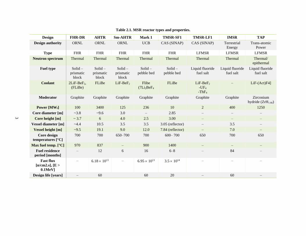
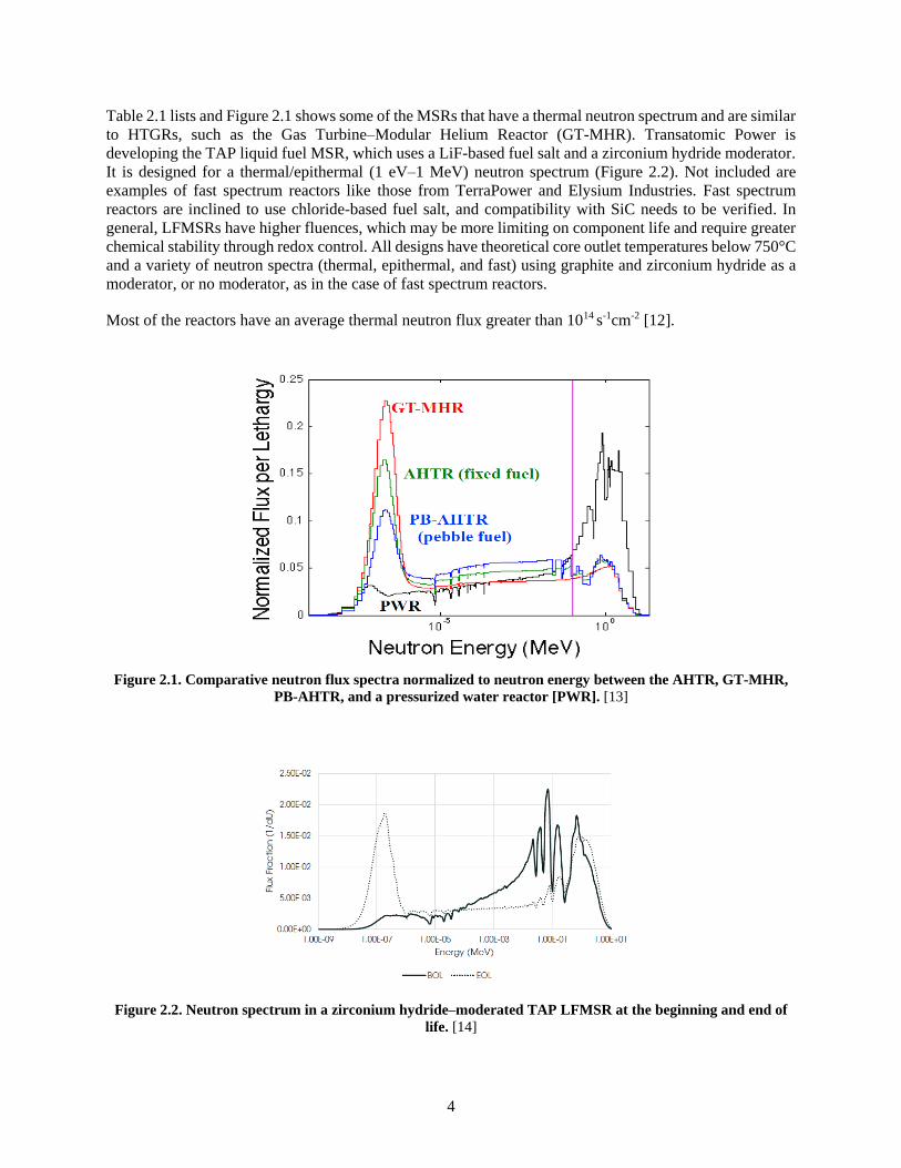
Table 2.1 lists and Figure 2.1 shows some of the MSRs that have a thermal neutron spectrum and are similar
to HTGRs, such as the Gas Turbine–Modular Helium Reactor (GT-MHR). Transatomic Power is
developing the TAP liquid fuel MSR, which uses a LiF-based fuel salt and a zirconium hydride moderator.
It is designed for a thermal/epithermal (1 eV–1 MeV) neutron spectrum (Figure 2.2). Not included are
examples of fast spectrum reactors like those from TerraPower and Elysium Industries. Fast spectrum
reactors are inclined to use chloride-based fuel salt, and compatibility with SiC needs to be verified. In
general, LFMSRs have higher fluences, which may be more limiting on component life and require greater
chemical stability through redox control. All designs have theoretical core outlet temperatures below 750°C
and a variety of neutron spectra (thermal, epithermal, and fast) using graphite and zirconium hydride as a
moderator, or no moderator, as in the case of fast spectrum reactors.
Most of the reactors have an average thermal neutron flux greater than 1014 s-1cm-2 [12].
Figure 2.1. Comparative neutron flux spectra normalized to neutron energy between the AHTR, GT-MHR,
PB-AHTR, and a pressurized water reactor [PWR]. [13]
Figure 2.2. Neutron spectrum in a zirconium hydride–moderated TAP LFMSR at the beginning and end of
life. [14]
5
Passive safety is one of the most marketable features of MSRs. Past experience with fast reactors and
breeder reactors, has demonstrated inherent safety features in the design, such as a closed primary circuit,
salt freeze tanks, intermediate heat exchanger (IHX), and modular decay heat rejection using the accident-
ready primary reactor auxiliary control system (PRACS) and direct reactor auxiliary cooling system
(DRACS) [15]. The PRACS is designed to match the decay heat for the first 1–2 hours of a Loss of Forced
Convection (LOFC) accident, and the DRACS for the first 1–2 days. The DRACS is entirely buoyancy
driven. The IHX has the advantage of minimizing the impact of an accident or a loop break in the primary
system that affects the secondary system. In a Loss of Ultimate Heat Sink (LUHS) accident scenario, the
intermediate loop cooling is lost and the reactor scrams. As the temperature of the core rises, the fission in
the fuel ceases as a result of resonance broadening (Doppler effect), which is a strongly negative fuel
temperature reactivity feedback. An LOFC accident scenario is similar, in that—the reactor protection
system detects an off-normal condition and the reactor scrams.
The LOFC and LUHS scenarios are severe accidents with low probability. After an LOFC or LUHS
scenario has occurred, a worst-case accident scenario is the anticipated transient without scram scenario, in
which the reactor scram system fails to respond. Simplified calculations predict that the coolant will
equilibrate near the original fuel temperature, below 800°C, well below the coolant boiling point of about
1430°C (for FLiBe). The system response and reliability in these scenarios should be carefully
demonstrated.
2.2 TYPICAL APPLICATIONS FOR SIC COMPONENTS, FUNCTION, GENERAL
REQUIREMENTS, AND REACTOR LOCATION
Ceramic composite materials like SiC/SiC and carbon/carbon (C/C) composites are candidate structural
materials for use in nuclear reactor cores. Characteristics like high-temperature stability, oxidation and
corrosion resistance, and radiation tolerance make ceramic composites more attractive than other high-
temperature structural metals. Possible near-term uses for SiC/SiC reactor components in solid fuel
applications include
• Control or tie rod supports (block and pebble fuel types)
• Core support plates or fuel salt distribution plates (block and pebble fuel types)
• Core barrel (block and pebble fuel types)
• Fuel and control blade assembly supports (block fuel types)
• Reactor core supports (block and pebble fuel types)
• Possible replacement for the C/C guide tubes and fuel assembly mechanical structure (block and
pebble fuel types)
• Instrumentation sleeves or other barriers between metal and salt for high temperature interaction.
(block and pebble fuel types)
• Wetted refueling mechanisms
For liquid fuel applications, it is foreseen that SiC/SiC fiber composites can replace some primary loop
components currently identified for nickel-based alloys. The SiC/SiC composites are both corrosion tolerant
and approved for high-temperature nuclear applications under the ASME Boiler and Pressure Vessel Code
(BPVC) Section III. These components can include primary loop piping, reactor vessel, valves, pumps, and
heat exchangers [14]. In a pebble fuel, a chemical vapor deposition (CVD) SiC layer ensures the structural
integrity of the particle under constant pressure and helps to retain fission products. In the case of zirconium
hydride–moderator reactors, the material hermeticity properties will be significant in the event of hydrogen
outgassing [16]. CVD SiC in the fuel and SiC/SiC composites for structural materials should be analyzed
separately, although the latter is the focus of this report.
6
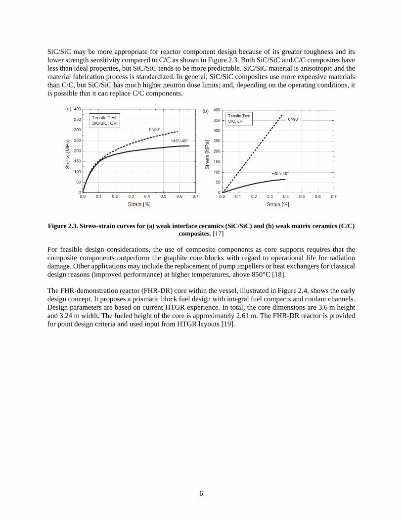
SiC/SiC may be more appropriate for reactor component design because of its greater toughness and its
lower strength sensitivity compared to C/C as shown in Figure 2.3. Both SiC/SiC and C/C composites have
less than ideal properties, but SiC/SiC tends to be more predictable. SiC/SiC material is anisotropic and the
material fabrication process is standardized. In general, SiC/SiC composites use more expensive materials
than C/C, but SiC/SiC has much higher neutron dose limits; and, depending on the operating conditions, it
is possible that it can replace C/C components.
Figure 2.3. Stress-strain curves for (a) weak interface ceramics (SiC/SiC) and (b) weak matrix ceramics (C/C)
composites. [17]
For feasible design considerations, the use of composite components as core supports requires that the
composite components outperform the graphite core blocks with regard to operational life for radiation
damage. Other applications may include the replacement of pump impellers or heat exchangers for classical
design reasons (improved performance) at higher temperatures, above 850°C [18].
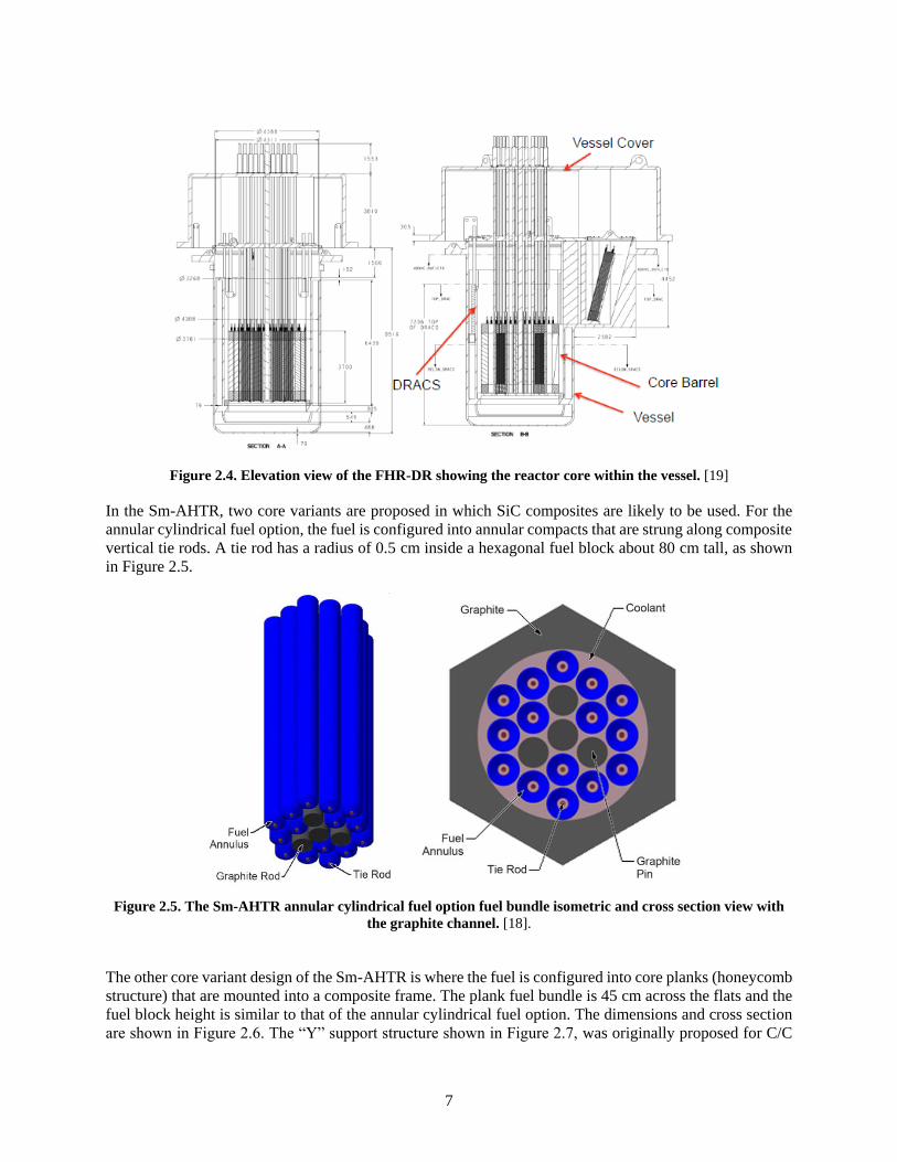
The FHR-demonstration reactor (FHR-DR) core within the vessel, illustrated in Figure 2.4, shows the early
design concept. It proposes a prismatic block fuel design with integral fuel compacts and coolant channels.
Design parameters are based on current HTGR experience. In total, the core dimensions are 3.6 m height
and 3.24 m width. The fueled height of the core is approximately 2.61 m. The FHR-DR reactor is provided
for point design criteria and used input from HTGR layouts [19].
7
Figure 2.4. Elevation view of the FHR-DR showing the reactor core within the vessel. [19]
In the Sm-AHTR, two core variants are proposed in which SiC composites are likely to be used. For the
annular cylindrical fuel option, the fuel is configured into annular compacts that are strung along composite
vertical tie rods. A tie rod has a radius of 0.5 cm inside a hexagonal fuel block about 80 cm tall, as shown
in Figure 2.5.
Figure 2.5. The Sm-AHTR annular cylindrical fuel option fuel bundle isometric and cross section view with
the graphite channel. [18].
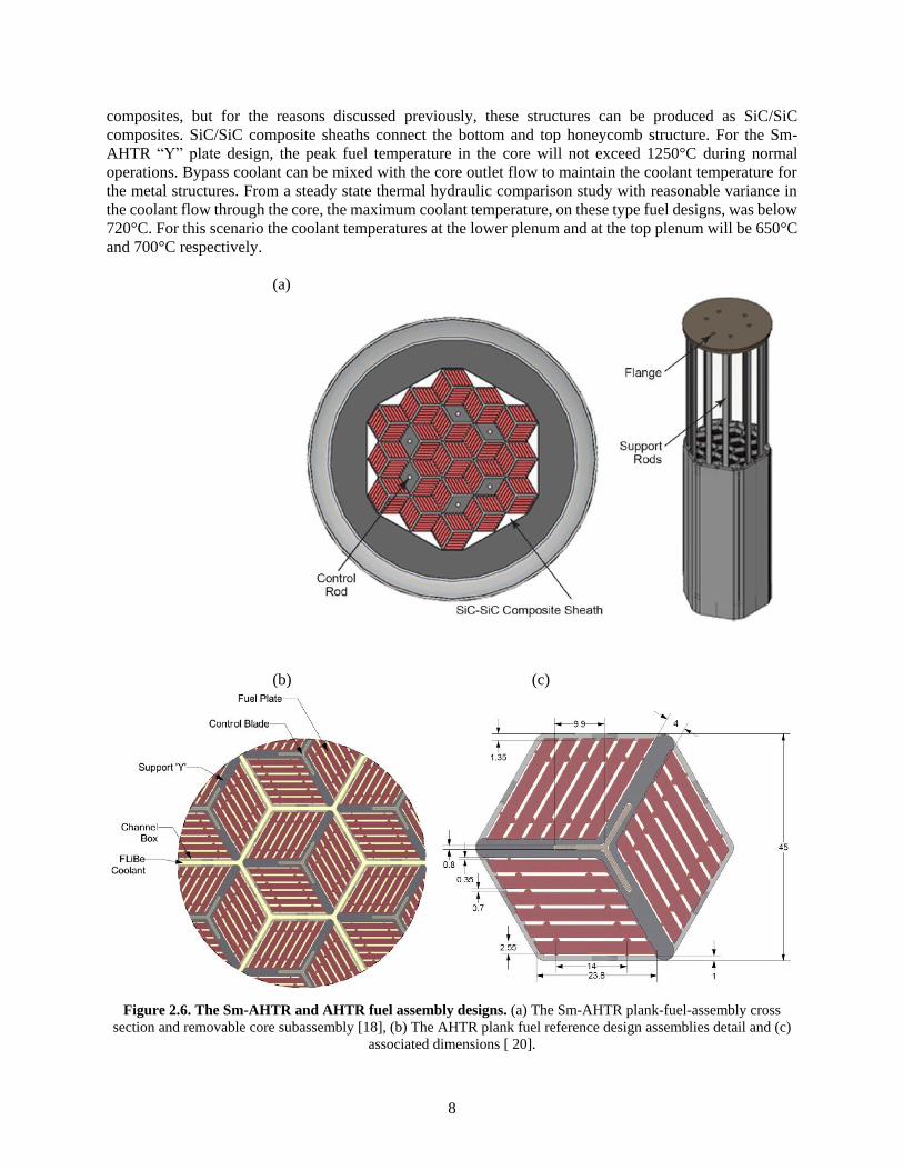
The other core variant design of the Sm-AHTR is where the fuel is configured into core planks (honeycomb
structure) that are mounted into a composite frame. The plank fuel bundle is 45 cm across the flats and the
fuel block height is similar to that of the annular cylindrical fuel option. The dimensions and cross section
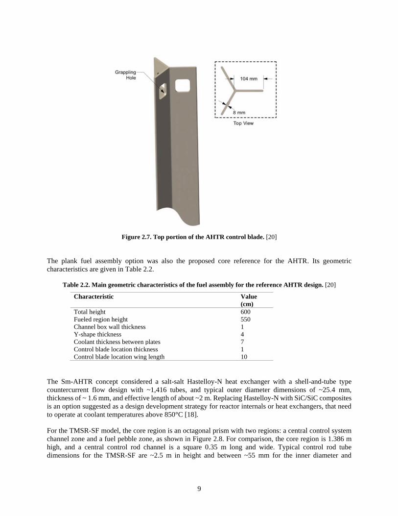
are shown in Figure 2.6. The “Y” support structure shown in Figure 2.7, was originally proposed for C/C
8
composites, but for the reasons discussed previously, these structures can be produced as SiC/SiC
composites. SiC/SiC composite sheaths connect the bottom and top honeycomb structure. For the Sm-
AHTR “Y” plate design, the peak fuel temperature in the core will not exceed 1250°C during normal
operations. Bypass coolant can be mixed with the core outlet flow to maintain the coolant temperature for
the metal structures. From a steady state thermal hydraulic comparison study with reasonable variance in
the coolant flow through the core, the maximum coolant temperature, on these type fuel designs, was below
720°C. For this scenario the coolant temperatures at the lower plenum and at the top plenum will be 650°C
and 700°C respectively.
(a)
(b) (c)
Figure 2.6. The Sm-AHTR and AHTR fuel assembly designs. (a) The Sm-AHTR plank-fuel-assembly cross
section and removable core subassembly [18], (b) The AHTR plank fuel reference design assemblies detail and (c)
associated dimensions [ 20].
9
Figure 2.7. Top portion of the AHTR control blade. [20]
The plank fuel assembly option was also the proposed core reference for the AHTR. Its geometric
characteristics are given in Table 2.2.
Table 2.2. Main geometric characteristics of the fuel assembly for the reference AHTR design. [20]
Characteristic Value
(cm)
Total height 600
Fueled region height 550
Channel box wall thickness 1
Y-shape thickness 4
Coolant thickness between plates 7
Control blade location thickness 1
Control blade location wing length 10
The Sm-AHTR concept considered a salt-salt Hastelloy-N heat exchanger with a shell-and-tube type
countercurrent flow design with ~1,416 tubes, and typical outer diameter dimensions of ~25.4 mm,
thickness of ~ 1.6 mm, and effective length of about ~2 m. Replacing Hastelloy-N with SiC/SiC composites
is an option suggested as a design development strategy for reactor internals or heat exchangers, that need
to operate at coolant temperatures above 850°C [18].
For the TMSR-SF model, the core region is an octagonal prism with two regions: a central control system
channel zone and a fuel pebble zone, as shown in Figure 2.8. For comparison, the core region is 1.386 m
high, and a central control rod channel is a square 0.35 m long and wide. Typical control rod tube
dimensions for the TMSR-SF are ~2.5 m in height and between ~55 mm for the inner diameter and
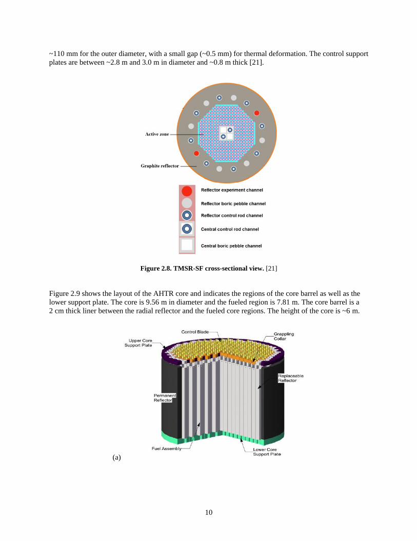
10
~110 mm for the outer diameter, with a small gap (~0.5 mm) for thermal deformation. The control support
plates are between ~2.8 m and 3.0 m in diameter and ~0.8 m thick [21].
Figure 2.8. TMSR-SF cross-sectional view. [21]
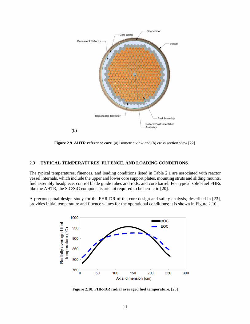
Figure 2.9 shows the layout of the AHTR core and indicates the regions of the core barrel as well as the
lower support plate. The core is 9.56 m in diameter and the fueled region is 7.81 m. The core barrel is a
2 cm thick liner between the radial reflector and the fueled core regions. The height of the core is ~6 m.
(a)
11
(b)
Figure 2.9. AHTR reference core. (a) isometric view and (b) cross section view [22].
2.3 TYPICAL TEMPERATURES, FLUENCE, AND LOADING CONDITIONS
The typical temperatures, fluences, and loading conditions listed in Table 2.1 are associated with reactor
vessel internals, which include the upper and lower core support plates, mounting struts and sliding mounts,
fuel assembly headpiece, control blade guide tubes and rods, and core barrel. For typical solid-fuel FHRs
like the AHTR, the SiC/SiC components are not required to be hermetic [20].
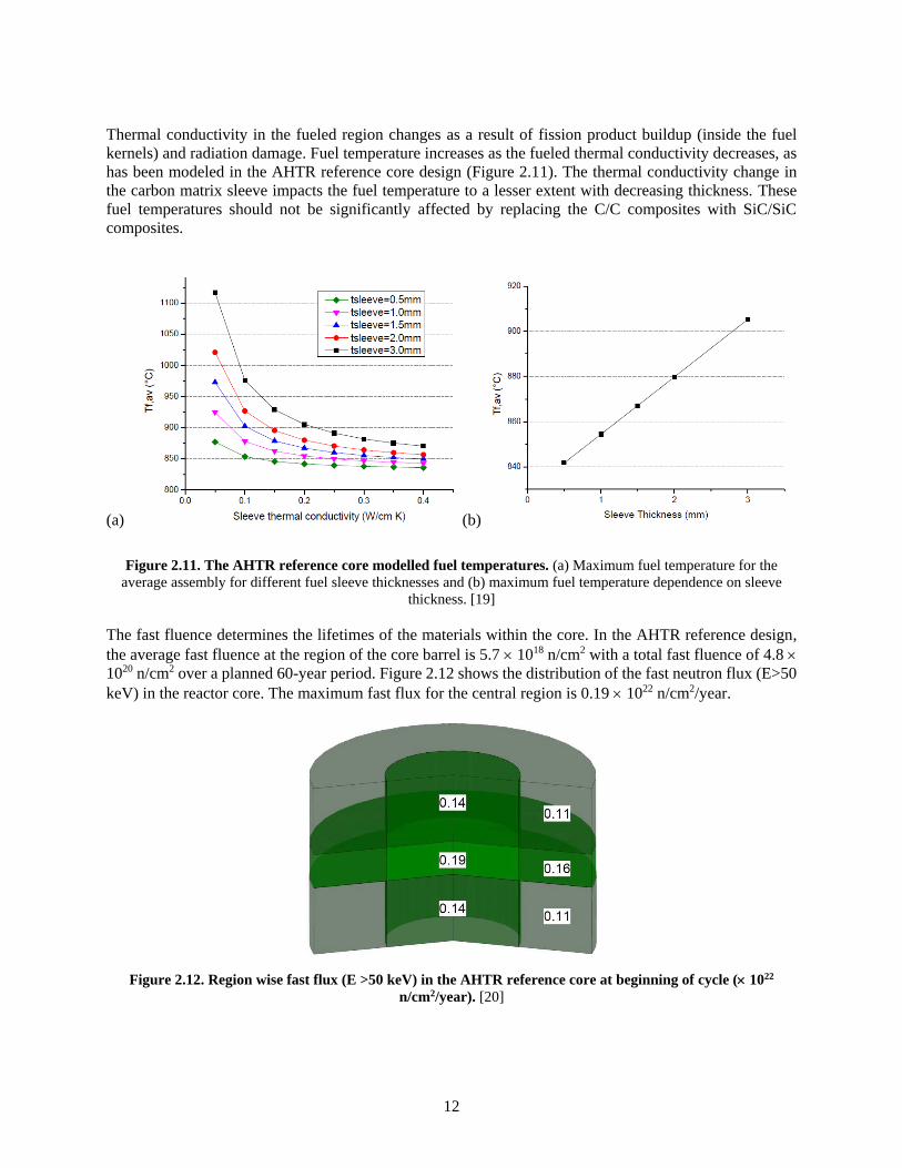
A preconceptual design study for the FHR-DR of the core design and safety analysis, described in [23],
provides initial temperature and fluence values for the operational conditions; it is shown in Figure 2.10.
Figure 2.10. FHR-DR radial averaged fuel temperature. [23]
12
Thermal conductivity in the fueled region changes as a result of fission product buildup (inside the fuel
kernels) and radiation damage. Fuel temperature increases as the fueled thermal conductivity decreases, as
has been modeled in the AHTR reference core design (Figure 2.11). The thermal conductivity change in
the carbon matrix sleeve impacts the fuel temperature to a lesser extent with decreasing thickness. These
fuel temperatures should not be significantly affected by replacing the C/C composites with SiC/SiC
composites.
(a) (b)
Figure 2.11. The AHTR reference core modelled fuel temperatures. (a) Maximum fuel temperature for the
average assembly for different fuel sleeve thicknesses and (b) maximum fuel temperature dependence on sleeve
thickness. [19]
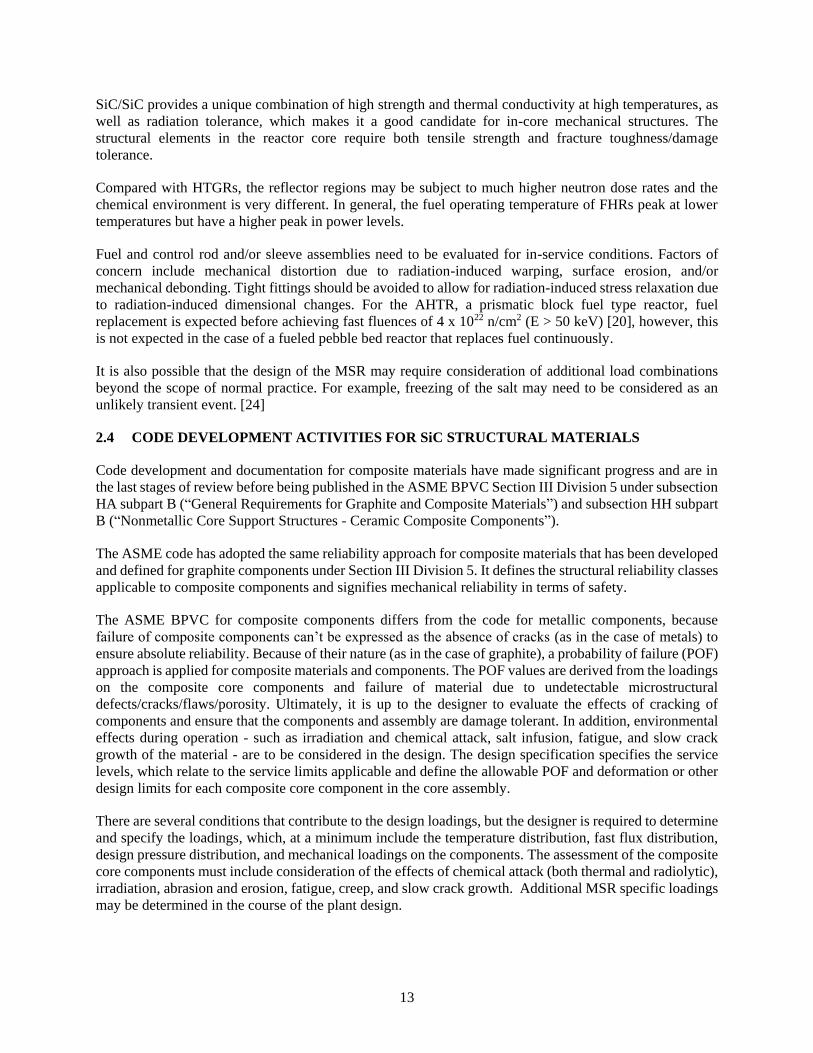
The fast fluence determines the lifetimes of the materials within the core. In the AHTR reference design,
the average fast fluence at the region of the core barrel is 5.7 1018 n/cm2 with a total fast fluence of 4.8
1020 n/cm2 over a planned 60-year period. Figure 2.12 shows the distribution of the fast neutron flux (E>50
keV) in the reactor core. The maximum fast flux for the central region is 0.19 1022 n/cm2/year.
Figure 2.12. Region wise fast flux (E >50 keV) in the AHTR reference core at beginning of cycle ( 1022
n/cm2/year). [20]
13
SiC/SiC provides a unique combination of high strength and thermal conductivity at high temperatures, as
well as radiation tolerance, which makes it a good candidate for in-core mechanical structures. The
structural elements in the reactor core require both tensile strength and fracture toughness/damage
tolerance.
Compared with HTGRs, the reflector regions may be subject to much higher neutron dose rates and the
chemical environment is very different. In general, the fuel operating temperature of FHRs peak at lower
temperatures but have a higher peak in power levels.
Fuel and control rod and/or sleeve assemblies need to be evaluated for in-service conditions. Factors of
concern include mechanical distortion due to radiation-induced warping, surface erosion, and/or
mechanical debonding. Tight fittings should be avoided to allow for radiation-induced stress relaxation due
to radiation-induced dimensional changes. For the AHTR, a prismatic block fuel type reactor, fuel
replacement is expected before achieving fast fluences of 4 x 10²² n/cm2 (E > 50 keV) [20], however, this
is not expected in the case of a fueled pebble bed reactor that replaces fuel continuously.
It is also possible that the design of the MSR may require consideration of additional load combinations
beyond the scope of normal practice. For example, freezing of the salt may need to be considered as an
unlikely transient event. [24]
2.4 CODE DEVELOPMENT ACTIVITIES FOR SiC STRUCTURAL MATERIALS
Code development and documentation for composite materials have made significant progress and are in
the last stages of review before being published in the ASME BPVC Section III Division 5 under subsection
HA subpart B (“General Requirements for Graphite and Composite Materials”) and subsection HH subpart
B (“Nonmetallic Core Support Structures - Ceramic Composite Components”).
The ASME code has adopted the same reliability approach for composite materials that has been developed
and defined for graphite components under Section III Division 5. It defines the structural reliability classes
applicable to composite components and signifies mechanical reliability in terms of safety.
The ASME BPVC for composite components differs from the code for metallic components, because
failure of composite components can’t be expressed as the absence of cracks (as in the case of metals) to
ensure absolute reliability. Because of their nature (as in the case of graphite), a probability of failure (POF)
approach is applied for composite materials and components. The POF values are derived from the loadings
on the composite core components and failure of material due to undetectable microstructural
defects/cracks/flaws/porosity. Ultimately, it is up to the designer to evaluate the effects of cracking of
components and ensure that the components and assembly are damage tolerant. In addition, environmental
effects during operation - such as irradiation and chemical attack, salt infusion, fatigue, and slow crack
growth of the material - are to be considered in the design. The design specification specifies the service
levels, which relate to the service limits applicable and define the allowable POF and deformation or other
design limits for each composite core component in the core assembly.
There are several conditions that contribute to the design loadings, but the designer is required to determine
and specify the loadings, which, at a minimum include the temperature distribution, fast flux distribution,
design pressure distribution, and mechanical loadings on the components. The assessment of the composite
core components must include consideration of the effects of chemical attack (both thermal and radiolytic),
irradiation, abrasion and erosion, fatigue, creep, and slow crack growth. Additional MSR specific loadings
may be determined in the course of the plant design.
14
Because of the considerable design flexibility in the architecture, structure, and properties for SiC/SiC and
C/C composites, the composite material would need to conform to the requirements of the materials
specification/s in the construction specification developed by the designer. Each component will have a
detailed specification for the loading conditions set out in the code.
Besides the physical and mechanical material properties required for design, the material specification
incorporates the irradiation effects, which include
• dimensional change
• irradiation creep coefficient
• coefficient of thermal expansion
• tensile strength (ultimate and proportional limit values)
• elastic modulus
• thermal conductivity
For the evaluation of chemical conditions, the material specification also requires as a minimum
• tensile strength (ultimate and proportional limit values)
• elastic modulus (dynamic)
• thermal conductivity
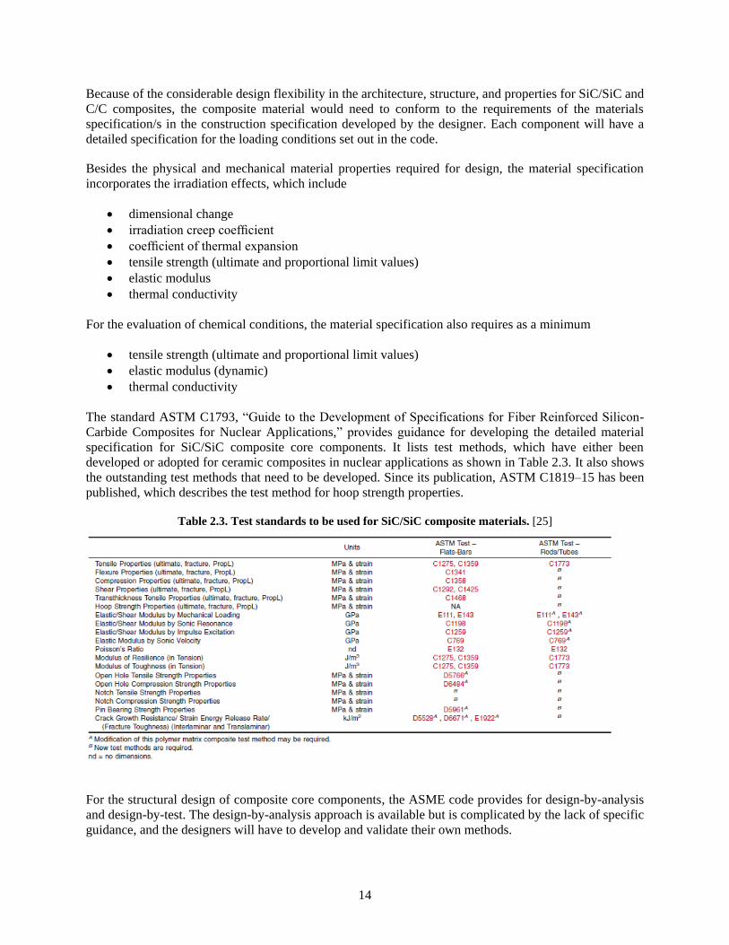
The standard ASTM C1793, “Guide to the Development of Specifications for Fiber Reinforced Silicon-
Carbide Composites for Nuclear Applications,” provides guidance for developing the detailed material
specification for SiC/SiC composite core components. It lists test methods, which have either been
developed or adopted for ceramic composites in nuclear applications as shown in Table 2.3. It also shows
the outstanding test methods that need to be developed. Since its publication, ASTM C1819–15 has been
published, which describes the test method for hoop strength properties.
Table 2.3. Test standards to be used for SiC/SiC composite materials. [25]
For the structural design of composite core components, the ASME code provides for design-by-analysis
and design-by-test. The design-by-analysis approach is available but is complicated by the lack of specific
guidance, and the designers will have to develop and validate their own methods.
15
For the integrated structure, the distortion or deformation (due to temperature or irradiation) of individual
composite core components should not cause constraints by hindering expansion or shrinkage. Furthermore,
the differential strains inside the core assembly and in the surrounding structures should not lead to stresses
that exceed the requirements for acceptability defined in the developed design rules.
The design rules do not make use of a theory for combining stresses. Instead, the design approach requires
a comparison between the maximum stress (in the dominant failure mode) resulting from the loading of the
component, and the stress (in the same mode) at failure of the material. Stress analysis is to be performed
on unirradiated, irradiated and oxidized (the effect of chemical attack) composite core components. For the
non-irradiated core components, an elastic analysis need to be performed without accounting for irradiation
damage with the exception of thermal conductivity that is used for thermal stress prediction. (Lastly
mentioned is for cases where the dose exceeds 0.001 dpa.) For analysis on the irradiated composite core
components, irradiation-induced property changes on the material and the development of stresses in the
components shall be accounted for. For analysis on oxidized core components, the effect of chemical attack
on the dimensions and the distribution of material properties in the components shall be considered. The
designer is responsible for the accuracy and acceptability of the analysis methods used. The allowable stress
values depend on the POF, which is derived from the structural reliability class of the composite core
component and the service level of the load. The design strength values for a defined POF are retrieved
from the Material Data Sheet of the specific ceramic composite material. The allowable stress values for
tensile stresses, compressive stresses, bending, and shear stresses are to be determined from the measured
and defined material design strengths in tension, compression, bending, shear, or another failure mode,
respectively.
It will be required to indicate the changes in physical and mechanical properties due to neutron irradiation
and chemical interaction at sufficient intervals. Changes must be reported over the design fluence or
chemical partial pressure and temperature ranges, as a function of fluence or as a function of the chemical
partial pressure, in the case of irradiation and chemical attack, respectively. If the composite material is
anisotropic, differentiation with respect to anisotropic orientation is required in reporting the property
changes. An important takeaway is that SiC/SiC composites are used as a material by design instead of a
material in design. The material architecture, and thus its properties, can be adjusted to match the
application.
In completing the code design of the components, the general approach is to differentiate between primary
loads (due to external forces or pressure) and secondary loads (due to irradiation induced swelling/shrinkage
and incompatible thermal strains). This approach is generally applicable to MSRs as well.
For structural design, the experience, data, and/or models from HTGRs can be applied to FHRs [26] with a
major operational difference that the primary loads tend to be lower for FHRs after reactor startup. Near-
neutral buoyancy reduces the gravity loads, and pressures are near atmospheric. Considering the core
structure, the graphite blocks will float in the salt if unrestrained. In general, the buoyancy effect will
transfer the loads from the core barrel support plate to the upper core internals in the area where the control
rod guide tubes are connected. The graphite structure will need to be tied down by upper and lower plates
with weights higher than the buoyancy force. Reflector blocks may need to be kept circumferentially
aligned by mechanisms like pins, keys, and/or belts that allow for radial thermal expansion.
The ASME composite code in its current state can be used as a base for FHRs. The FHR loads are expected
to be different from HTGR loads, but itmust be considered to show that the structures maintain adequate
levels of integrity throughout the design life. Furthermore, effects like thermal striping and flow-induced
vibration are likely to be important in FHR designs while less significant to HTGR designs (because the
salt is a better heat transfer material and more dense than helium). The code in its final stages would need
to be reviewed to ensure that it makes sufficient provision to address these effects.
16
Additionally, the code may have to be assessed for its compatibility with LFMSR designs, with a focus on
possible materials interactions with the actinides and fission products to be found in the coolant solution.
In its current form, the code addresses how to design for chemical attack by radionuclides. Specific guidance
may improve how the code addresses the effects caused by actinide and fission product interaction.
2.5 LICENSING ASPECTS
Aside from the ARE and MSRE test reactors, no MSR, specifically no FHR class reactor, has ever been
constructed to serve as the basis for the safety, sustainability, or licensing case for U.S. Nuclear Regulatory
Commission (NRC) review. However, the NRC has experience in previously licensed liquid metal reactors
and HTGRs. Because the FHR combines existing MSR technology with proven high-temperature TRISO
fuel technology like the HTGR, it supports a reasonably strong case for FHR licensing activities. The code
in its current state under Section III subsection HH subpart B has matured to a point that it is close to
publication and is applicable to HTGRs and solid fuel MSRs. Because of the lack of a demonstration reactor
and a need to validate the rules, it is necessary to develop a technical basis document that supports the
conditions described in the code with benchmarking data.
The licensing framework for solid fuel MSR design and analysis of passive safety and accident-ready
systems, structures, and components is driven by earlier work done in the Next Generation Nuclear Plants
(NGNP) forum and Pebble Bed Modular Reactor (PBMR) programs as discussed at various collaborative
FHR workshops in the past few years [27-29]. The framework is mostly applicable to fuel but is possibly
relevant to the safety design criteria for SiC components; which, in some instances, are part of the fuel
assembly. The criteria include (1) maintaining core and reactor vessel geometry, (2) controlling heat
generation (reactivity), and (3) maintaining control of radionuclides. Guidance from NUREG 1537 and
NUREG 800 will likely be used as input for licensing of non-power test reactors and commercial reactors,
respectively, after a gap analysis has been performed [13]. Another initiative under the DOE–Nuclear
Energy Initiative–NRC licensing modernization program, the Licensing Technical Requirements
Modernization Project, has the task of identifying gaps in the regulatory process for non-LWR designs,
which includes HTRs and is performance based. It is possible that risk-informed licensing will form the
basis for MSR regulation [30,31].
Without an operational reactor, the safety basis will rely on analyses supported by tests that rely on past
operating experience. The information used is generated within a quality assurance program, typically in
accordance with 10 CFR 50, Appendix B. This program may be implemented according to ASME NQA-
1, considering a graded approach of applicability and importance.
Based on previous detailed system design analysis, mechanisms that can change the core internals and
reactor vessel geometry include fuel movement, thermal expansion during normal transients, slow materials
processes such as irradiation-induced swelling and corrosion, and thermal and mechanical stresses during
transients and accidents. For the reactivity control systems, functional requirements applicable to the control
rod sleeves may include ensuring the channel geometry for high-reliability insertion. This may be different
in the case of liquid fuel designs, which have reduced safety performance requirements. Daily fuel addition
and strong inherent negative temperature reactivity feedback results in minimal excess reactivity. The
design rules discussed in the code largely address these mechanistic behaviors; but they do not include the
use of ceramics as coating or barrier materials to act as a control for radionuclides, even though they address
aspects regarding chemical attack. This is considered outside the scope of the code, which is to address and
ensure pressure retention and structural integrity.
To close the gap for licensing, a skilled workforce who understand the underlying complexities of SiC/SiC
composite materials and who are knowledgeable regarding the design approach are needed within the NRC
and the wider community to overcome the remaining safety concerns.
17
As previously mentioned, the code may have to accommodate additional guidance associated with LFMSR
designs detailing the effects of fuel interaction, which currently are not explicitly addressed.
2.6 THE TECHNOLOGY GAPS IN THE DESIGN METHODOLOGY
To enable the development and demonstration of an operating FHR for commercial deployment, several
infrastructure and maturation goals have been identified [19]. They include developing and demonstrating
a licensing path for advanced reactors in general, demonstrating key fabrication techniques for reactor
components, and developing a supply chain for FHR-specific components and materials. Key system and
component technologies include fuel assembly and control rod systems. SiC/SiC composites have been
identified as a potential candidate for various components within these systems.
A number of activities have been undertaken, including establishing design rules and standards and
generating experimental data on irradiation effects. Some of these activities are also supported by efforts
from the LWR and advanced fuels technology communities that are driving the development of the SiC
fuel cladding and core component applications for accident-tolerant fuel designs.
Significant progress has been made with regards to understanding the irradiation performance
characteristics, but work is required to understand the mechanical design limitations for SiC/SiC
composites. The stress applications for MSR designs are still unknown, and benchmark data validating the
analysis of the structural design are required to support the limiting conditions described in the composites
code. These needs can be supported by the development of a technical basis document. The code also needs
to be assessed to ensure that it sufficiently addresses material effects due to material interactions with
actinides and fission products.
For the development of the SiC/SiC composite Material Data Sheet/s, and in light of Table 2.3 as listed in
ASTM C1793, there are still a large number of outstanding ASTM test standards that may be critical for
composite core components—such as fuel or control rod sleeve applications. Some rod/tube test standards
are in development, including
• Open-hole tensile strength of fiber-reinforced advanced ceramic composites
• Flexure tube strength at room-temperature testing
Other new standards, including “Guide to Oxidation Exposure Testing of Advanced Ceramics” and
“Torsional Shear Strength of Advanced Ceramic Bonded Joints” are also in development.
Besides the current efforts, there are several rod/tube standards applicable to HTRs in general, such as
compression, shear, trans-thickness tensile, and hoop strength properties (at room- and/or high-temperature
testing). Pin bearing strength and crack growth resistance or strain energy release rate are listed as required
test methods and need development. For molten salt applications, new test standards for high-temperature
testing retained strength, degradation, and elastic constants in corrosive environments are important and
currently lacking. A few existing test standards were identified that require modifications to incorporate
SiC/SiC matrix composites. These tests include elastic/shear modulus by mechanical loading, sonic
resonance, impulse excitation, and sonic velocity, as well as Poisson’s ratio, modulus of resilience, and
modulus of toughness.
Once developed, the new standard tests need to be performed via interlaboratory round-robin testing, with
the intent to conduct tests repeatedly under the same conditions and by doing so establish precision and
bias statements to be adopted within the standards.

18
3. MATERIALS AND MANUFACTURING
3.1 COMPOSITES: FIBERS, MATRICES, AND INTERFACE
SiC materials of interest for nuclear structural applications are mostly continuous fiber-reinforced ceramics
matrix composites, which consist of SiC fiber, SiC matrix, and a carbon interface between the fiber and
matrix [32] (Figure 3.1). This section describes fabrication and integration technologies for potential MSR
applications.
Figure 3.1. Appearance of continuous SiC fiber–reinforced SiC matrix composites fabricated by CVI.
3.1.1 Fiber
Fiber is a key element of SiC/SiC composites that determines the ultimate strength of a composite material
[33]. Nuclear-grade SiC fiber is considered near-stoichiometric and highly crystalline because of its
dimensional stability under irradiation compared with non-stoichiometric and amorphous-like SiC fibers
[32]. This generation III class of SiC fibers that can be considered for nuclear applications includes Hi-
Nicalon Type S (HNS; Nippon Carbon Co., Tokyo, Japan), Tyranno SA3 (SA3; Ube Industries Ltd., Ube,
Japan), and Sylramic (SYL; COI Ceramics, San Diego). Information on the properties of these fibers can
be found elsewhere [34]. Briefly, they have similar mechanical properties—Young’s modulus of ~400 GPa
and room-temperature tensile strength of >2 GPa—but their thermal properties may differ significantly.
Only the HNS and SA3 SiC fibers are currently considered for nuclear applications because the boron (a
neutron absorber) present in SYL is considered an impurity and makes it unfavorable.
Given certain properties for the constituent materials, the composite properties are determined by the fiber
architecture. The reinforcing fibers provide benefits such as strength and toughness most effectively in
directions parallel to the fiber axis. More precisely, the composite properties are to a large extent determined
by the volume fractions and orientations of the fibers in relation to the orientation of interest for certain
properties. Therefore, tailoring the fiber architecture is a key to optimizing the composite mechanical
19
properties [32]. In addition, fiber woven technology is essential for near-net shape processing. Currently,
fiber architectures include 2-direction layups in the form of woven fabrics, 2.5-direction layups with cross
weaving through the woven fabrics, and 3-direction orthogonal weaves. The architecture will be chosen
depending on the property requirements. Examples of the fiber architectures with tube geometries are
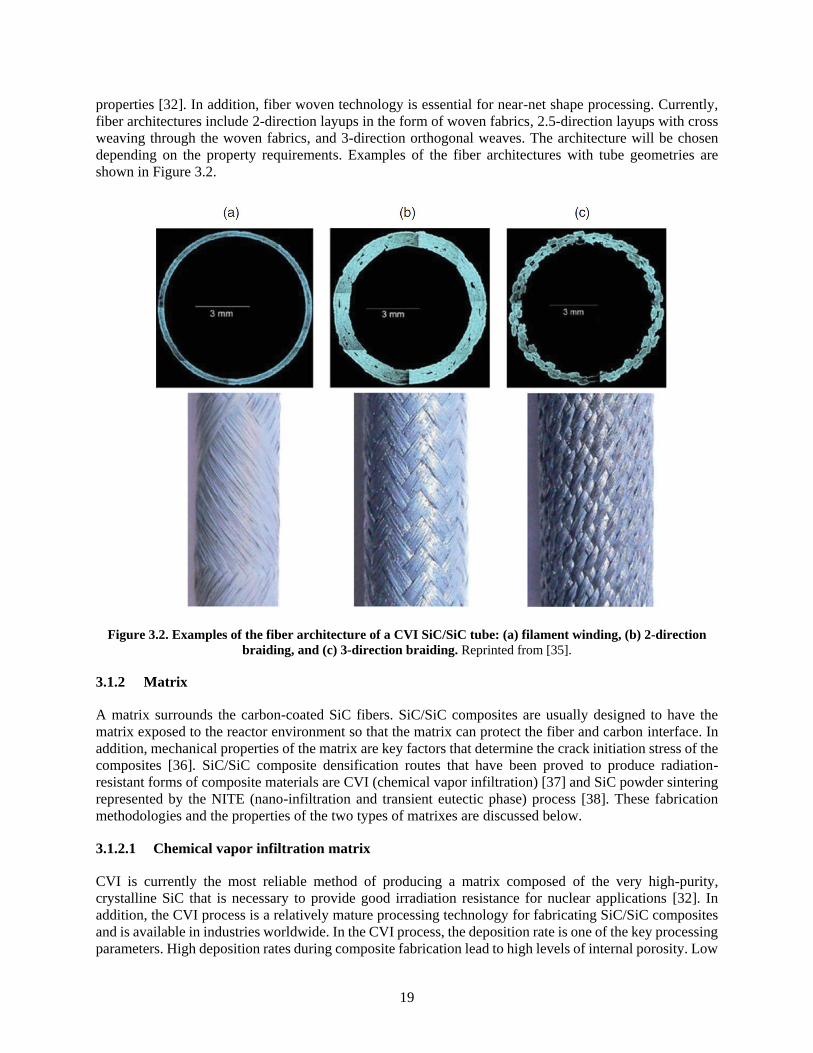
shown in Figure 3.2.
Figure 3.2. Examples of the fiber architecture of a CVI SiC/SiC tube: (a) filament winding, (b) 2-direction
braiding, and (c) 3-direction braiding. Reprinted from [35].
3.1.2 Matrix
A matrix surrounds the carbon-coated SiC fibers. SiC/SiC composites are usually designed to have the
matrix exposed to the reactor environment so that the matrix can protect the fiber and carbon interface. In
addition, mechanical properties of the matrix are key factors that determine the crack initiation stress of the
composites [36]. SiC/SiC composite densification routes that have been proved to produce radiation-
resistant forms of composite materials are CVI (chemical vapor infiltration) [37] and SiC powder sintering
represented by the NITE (nano-infiltration and transient eutectic phase) process [38]. These fabrication
methodologies and the properties of the two types of matrixes are discussed below.
3.1.2.1 Chemical vapor infiltration matrix
CVI is currently the most reliable method of producing a matrix composed of the very high-purity,
crystalline SiC that is necessary to provide good irradiation resistance for nuclear applications [32]. In
addition, the CVI process is a relatively mature processing technology for fabricating SiC/SiC composites
and is available in industries worldwide. In the CVI process, the deposition rate is one of the key processing
parameters. High deposition rates during composite fabrication lead to high levels of internal porosity. Low
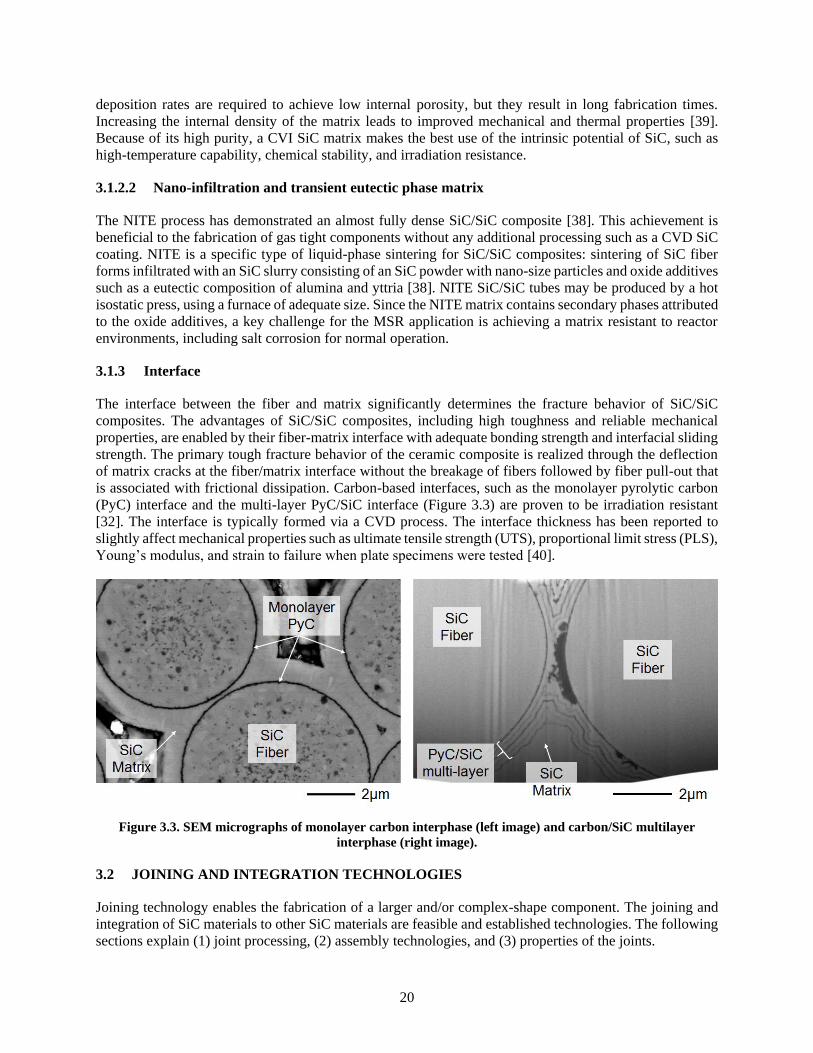
20
deposition rates are required to achieve low internal porosity, but they result in long fabrication times.
Increasing the internal density of the matrix leads to improved mechanical and thermal properties [39].
Because of its high purity, a CVI SiC matrix makes the best use of the intrinsic potential of SiC, such as
high-temperature capability, chemical stability, and irradiation resistance.
3.1.2.2 Nano-infiltration and transient eutectic phase matrix
The NITE process has demonstrated an almost fully dense SiC/SiC composite [38]. This achievement is
beneficial to the fabrication of gas tight components without any additional processing such as a CVD SiC
coating. NITE is a specific type of liquid-phase sintering for SiC/SiC composites: sintering of SiC fiber
forms infiltrated with an SiC slurry consisting of an SiC powder with nano-size particles and oxide additives
such as a eutectic composition of alumina and yttria [38]. NITE SiC/SiC tubes may be produced by a hot
isostatic press, using a furnace of adequate size. Since the NITE matrix contains secondary phases attributed
to the oxide additives, a key challenge for the MSR application is achieving a matrix resistant to reactor
environments, including salt corrosion for normal operation.
3.1.3 Interface
The interface between the fiber and matrix significantly determines the fracture behavior of SiC/SiC
composites. The advantages of SiC/SiC composites, including high toughness and reliable mechanical
properties, are enabled by their fiber-matrix interface with adequate bonding strength and interfacial sliding
strength. The primary tough fracture behavior of the ceramic composite is realized through the deflection
of matrix cracks at the fiber/matrix interface without the breakage of fibers followed by fiber pull-out that
is associated with frictional dissipation. Carbon-based interfaces, such as the monolayer pyrolytic carbon
(PyC) interface and the multi-layer PyC/SiC interface (Figure 3.3) are proven to be irradiation resistant
[32]. The interface is typically formed via a CVD process. The interface thickness has been reported to
slightly affect mechanical properties such as ultimate tensile strength (UTS), proportional limit stress (PLS),
Young’s modulus, and strain to failure when plate specimens were tested [40].
Figure 3.3. SEM micrographs of monolayer carbon interphase (left image) and carbon/SiC multilayer
interphase (right image).
3.2 JOINING AND INTEGRATION TECHNOLOGIES
Joining technology enables the fabrication of a larger and/or complex-shape component. The joining and
integration of SiC materials to other SiC materials are feasible and established technologies. The following
sections explain (1) joint processing, (2) assembly technologies, and (3) properties of the joints.
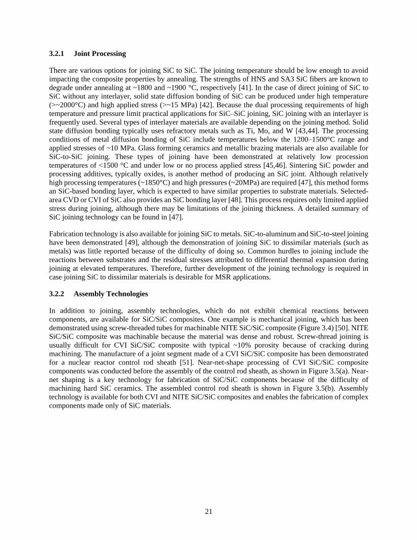
21
3.2.1 Joint Processing
There are various options for joining SiC to SiC. The joining temperature should be low enough to avoid
impacting the composite properties by annealing. The strengths of HNS and SA3 SiC fibers are known to
degrade under annealing at ~1800 and ~1900 °C, respectively [41]. In the case of direct joining of SiC to
SiC without any interlayer, solid state diffusion bonding of SiC can be produced under high temperature
(>~2000°C) and high applied stress (>~15 MPa) [42]. Because the dual processing requirements of high
temperature and pressure limit practical applications for SiC–SiC joining, SiC joining with an interlayer is
frequently used. Several types of interlayer materials are available depending on the joining method. Solid
state diffusion bonding typically uses refractory metals such as Ti, Mo, and W [43,44]. The processing
conditions of metal diffusion bonding of SiC include temperatures below the 1200–1500°C range and
applied stresses of ~10 MPa. Glass forming ceramics and metallic brazing materials are also available for
SiC-to-SiC joining. These types of joining have been demonstrated at relatively low procession
temperatures of <1500 °C and under low or no process applied stress [45,46]. Sintering SiC powder and
processing additives, typically oxides, is another method of producing an SiC joint. Although relatively
high processing temperatures (~1850°C) and high pressures (~20MPa) are required [47], this method forms
an SiC-based bonding layer, which is expected to have similar properties to substrate materials. Selected-
area CVD or CVI of SiC also provides an SiC bonding layer [48]. This process requires only limited applied
stress during joining, although there may be limitations of the joining thickness. A detailed summary of
SiC joining technology can be found in [47].
Fabrication technology is also available for joining SiC to metals. SiC-to-aluminum and SiC-to-steel joining
have been demonstrated [49], although the demonstration of joining SiC to dissimilar materials (such as
metals) was little reported because of the difficulty of doing so. Common hurdles to joining include the
reactions between substrates and the residual stresses attributed to differential thermal expansion during
joining at elevated temperatures. Therefore, further development of the joining technology is required in
case joining SiC to dissimilar materials is desirable for MSR applications.
3.2.2 Assembly Technologies
In addition to joining, assembly technologies, which do not exhibit chemical reactions between
components, are available for SiC/SiC composites. One example is mechanical joining, which has been
demonstrated using screw-threaded tubes for machinable NITE SiC/SiC composite (Figure 3.4) [50]. NITE
SiC/SiC composite was machinable because the material was dense and robust. Screw-thread joining is
usually difficult for CVI SiC/SiC composite with typical ~10% porosity because of cracking during
machining. The manufacture of a joint segment made of a CVI SiC/SiC composite has been demonstrated
for a nuclear reactor control rod sheath [51]. Near-net-shape processing of CVI SiC/SiC composite
components was conducted before the assembly of the control rod sheath, as shown in Figure 3.5(a). Near-
net shaping is a key technology for fabrication of SiC/SiC components because of the difficulty of
machining hard SiC ceramics. The assembled control rod sheath is shown in Figure 3.5(b). Assembly
technology is available for both CVI and NITE SiC/SiC composites and enables the fabrication of complex
components made only of SiC materials.
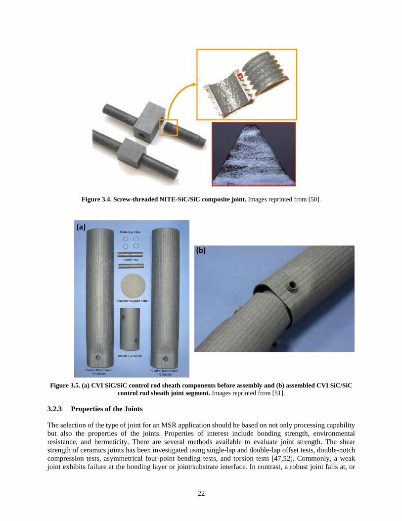
22
Figure 3.4. Screw-threaded NITE-SiC/SiC composite joint. Images reprinted from [50].
Figure 3.5. (a) CVI SiC/SiC control rod sheath components before assembly and (b) assembled CVI SiC/SiC
control rod sheath joint segment. Images reprinted from [51].
3.2.3 Properties of the Joints
The selection of the type of joint for an MSR application should be based on not only processing capability
but also the properties of the joints. Properties of interest include bonding strength, environmental
resistance, and hermeticity. There are several methods available to evaluate joint strength. The shear
strength of ceramics joints has been investigated using single-lap and double-lap offset tests, double-notch
compression tests, asymmetrical four-point bending tests, and torsion tests [47,52]. Commonly, a weak
joint exhibits failure at the bonding layer or joint/substrate interface. In contrast, a robust joint fails at, or
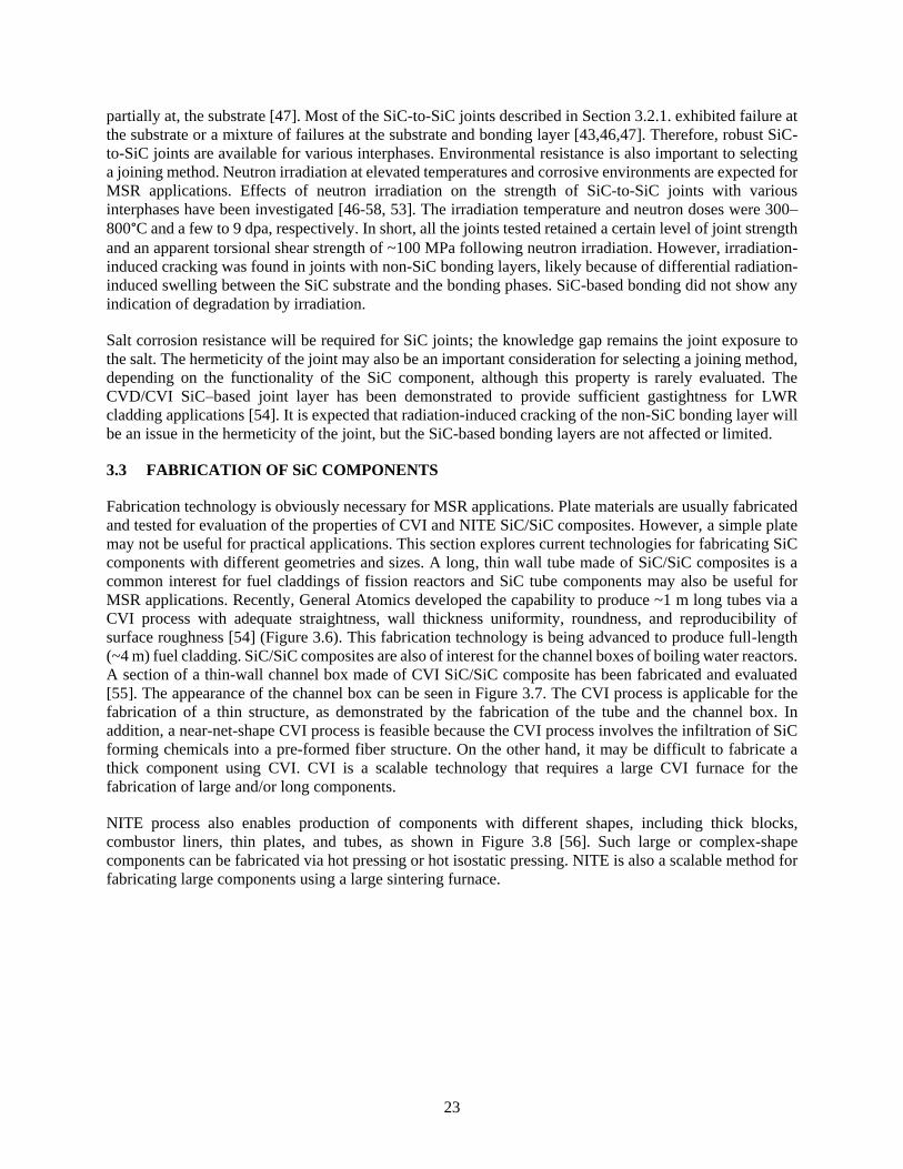
23
partially at, the substrate [47]. Most of the SiC-to-SiC joints described in Section 3.2.1. exhibited failure at
the substrate or a mixture of failures at the substrate and bonding layer [43,46,47]. Therefore, robust SiC-
to-SiC joints are available for various interphases. Environmental resistance is also important to selecting
a joining method. Neutron irradiation at elevated temperatures and corrosive environments are expected for
MSR applications. Effects of neutron irradiation on the strength of SiC-to-SiC joints with various
interphases have been investigated [46-58, 53]. The irradiation temperature and neutron doses were 300–
800°C and a few to 9 dpa, respectively. In short, all the joints tested retained a certain level of joint strength
and an apparent torsional shear strength of ~100 MPa following neutron irradiation. However, irradiation-
induced cracking was found in joints with non-SiC bonding layers, likely because of differential radiation-
induced swelling between the SiC substrate and the bonding phases. SiC-based bonding did not show any
indication of degradation by irradiation.
Salt corrosion resistance will be required for SiC joints; the knowledge gap remains the joint exposure to
the salt. The hermeticity of the joint may also be an important consideration for selecting a joining method,
depending on the functionality of the SiC component, although this property is rarely evaluated. The
CVD/CVI SiC–based joint layer has been demonstrated to provide sufficient gastightness for LWR
cladding applications [54]. It is expected that radiation-induced cracking of the non-SiC bonding layer will
be an issue in the hermeticity of the joint, but the SiC-based bonding layers are not affected or limited.
3.3 FABRICATION OF SiC COMPONENTS
Fabrication technology is obviously necessary for MSR applications. Plate materials are usually fabricated
and tested for evaluation of the properties of CVI and NITE SiC/SiC composites. However, a simple plate
may not be useful for practical applications. This section explores current technologies for fabricating SiC
components with different geometries and sizes. A long, thin wall tube made of SiC/SiC composites is a
common interest for fuel claddings of fission reactors and SiC tube components may also be useful for
MSR applications. Recently, General Atomics developed the capability to produce ~1 m long tubes via a
CVI process with adequate straightness, wall thickness uniformity, roundness, and reproducibility of
surface roughness [54] (Figure 3.6). This fabrication technology is being advanced to produce full-length
(~4 m) fuel cladding. SiC/SiC composites are also of interest for the channel boxes of boiling water reactors.
A section of a thin-wall channel box made of CVI SiC/SiC composite has been fabricated and evaluated
[55]. The appearance of the channel box can be seen in Figure 3.7. The CVI process is applicable for the
fabrication of a thin structure, as demonstrated by the fabrication of the tube and the channel box. In
addition, a near-net-shape CVI process is feasible because the CVI process involves the infiltration of SiC
forming chemicals into a pre-formed fiber structure. On the other hand, it may be difficult to fabricate a
thick component using CVI. CVI is a scalable technology that requires a large CVI furnace for the
fabrication of large and/or long components.
NITE process also enables production of components with different shapes, including thick blocks,
combustor liners, thin plates, and tubes, as shown in Figure 3.8 [56]. Such large or complex-shape
components can be fabricated via hot pressing or hot isostatic pressing. NITE is also a scalable method for
fabricating large components using a large sintering furnace.
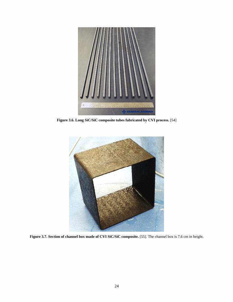
24
Figure 3.6. Long SiC/SiC composite tubes fabricated by CVI process. [54]
Figure 3.7. Section of channel box made of CVI SiC/SiC composite. [55]. The channel box is 7.6 cm in height.
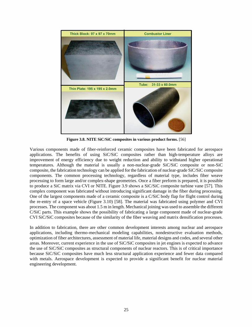
25
Figure 3.8. NITE SiC/SiC composites in various product forms. [56]
Various components made of fiber-reinforced ceramic composites have been fabricated for aerospace
applications. The benefits of using SiC/SiC composites rather than high-temperature alloys are
improvement of energy efficiency due to weight reduction and ability to withstand higher operational
temperatures. Although the material is usually a non-nuclear-grade SiC/SiC composite or non-SiC
composite, the fabrication technology can be applied for the fabrication of nuclear-grade SiC/SiC composite
components. The common processing technology, regardless of material type, includes fiber weave
processing to form large and/or complex-shape geometries. Once a fiber preform is prepared, it is possible
to produce a SiC matrix via CVI or NITE. Figure 3.9 shows a SiC/SiC composite turbine vane [57]. This
complex component was fabricated without introducing significant damage in the fiber during processing.
One of the largest components made of a ceramic composite is a C/SiC body flap for flight control during
the re-entry of a space vehicle (Figure 3.10) [58]. The material was fabricated using polymer and CVI
processes. The component was about 1.5 m in length. Mechanical joining was used to assemble the different
C/SiC parts. This example shows the possibility of fabricating a large component made of nuclear-grade
CVI SiC/SiC composites because of the similarity of the fiber weaving and matrix densification processes.
In addition to fabrication, there are other common development interests among nuclear and aerospace
applications, including thermo-mechanical modeling capabilities, nondestructive evaluation methods,
optimization of fiber architectures, assessment of material life, material designs and codes, and several other
areas. Moreover, current experience in the use of SiC/SiC composites in jet engines is expected to advance
the use of SiC/SiC composites as structural components of nuclear reactors. This is of critical importance
because SiC/SiC composites have much less structural application experience and fewer data compared
with metals. Aerospace development is expected to provide a significant benefit for nuclear material
engineering development.
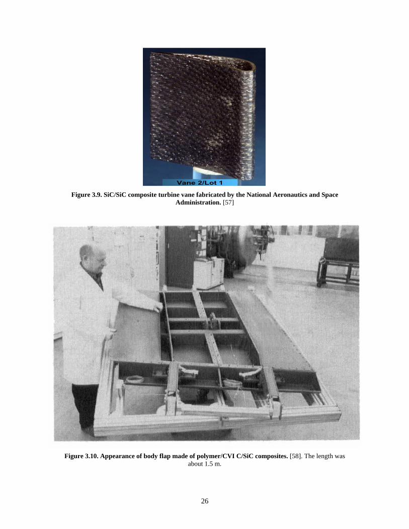
26
Figure 3.9. SiC/SiC composite turbine vane fabricated by the National Aeronautics and Space
Administration. [57]
Figure 3.10. Appearance of body flap made of polymer/CVI C/SiC composites. [58]. The length was
about 1.5 m.
27
3.4 TECHNOLOGY GAPS FOR SiC/SiC MATERIALS AND MANUFACTURING
For viable use of nuclear-grade SiC/SiC composites in MSR applications, it will be necessary to fabricate
large and/or complex-shape components. Although processing elements such as the fiber weaving process,
matrix densification, and joining/integration technologies are available for SiC/SiC composite materials,
demonstrations of component fabrication will be required. As mentioned in Section 2.4, design of the
SiC/SiC component is also required. Since the thermo-mechanical properties of SiC/SiC composites are
anisotropic and are tailorable, the fiber architecture and volume and the materials used in composite
constituents need to be optimized. Selection of the integration method will be key, as the limitations for the
joining process include minimizing processing damage to the composite. Furthermore, joints will need to
withstand typical reactor environments.
28
4. PROPERTIES AND RADIATION EFFECTS
4.1 IRRADIATION EFFECTS
Research and development of SiC ceramics and composites for various applications under different reactor
operating conditions has accumulated irradiation data for various temperature and dose conditions.
Currently, a rich database of mechanical and physical properties of irradiated monolithic SiC [59] and
SiC/SiC composites [32] are available. Such data are essential to assess the in-pile thermo-mechanical
performance of SiC-based components. This section presents key properties of SiC materials for nuclear
structural applications and identifies knowledge gaps in understanding the thermo-mechanical performance
of SiC materials in MSRs. In this section, 1 dpa-SiC is assumed to be equivalent to a dose of 1×1025 n/m2
(>0.1 MeV) [60].
4.1.1 Dimensional Stability
Dimensional stability under irradiation is mainly characterized by swelling and irradiation creep, which
potentially determine the service life of reactor core components. Swelling of high-purity SiC and CVI
SiC/SiC composites along the in-plane direction are very similar [61]. Swelling of SiC materials increases
with increasing neutron dose up to ~1 dpa and then saturates at temperatures ranging from ~200 to ~1000°C
[59]. Recently, this saturation swelling has been confirmed up to ~100 dpa [62]. The magnitude of swelling
is inversely proportional to the irradiation temperature. The details of swelling behavior are shown in Figure
4.1. At irradiation temperatures above ~1000°C, the lifetime neutron dose of SiC is potentially determined
by the requirement for dimensional stability, because SiC swelling is dose dependent [60].
Irradiation creep is a property that determines the dimensional stability under stress. Creep is known to be
accelerated under irradiation environments because of the generation of irradiation-induced defects. In the
case of SiC, irradiation creep has been explained by anisotropic swelling (more swelling along the tensile
stress direction) up to high doses [63, 64]. Irradiation creep strain of SiC has been shown to be significantly
smaller than the swelling; the instantaneous creep coefficient (stress-normalized creep strain) is 1×10⁻⁵ dpa-
1MPa-1 at 0.1dpa and 1×10⁻⁷ dpa-1MPa-1 beyond 1dpa for most monolithic SiC forms and SiC fibers [63,
64]. Therefore, the dimensional stability of SiC in an irradiation environment is mainly characterized by
swelling. Although there is currently little understanding regarding irradiation creep of SiC/SiC composites,
the current data set suggests that it won’t be a major issue for nuclear structural applications because of the
small creep strain of composite constituents, including both matrix and fibers [64].
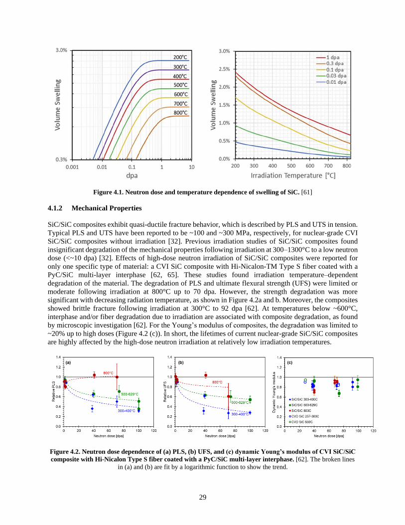
29
Figure 4.1. Neutron dose and temperature dependence of swelling of SiC. [61]
4.1.2 Mechanical Properties
SiC/SiC composites exhibit quasi-ductile fracture behavior, which is described by PLS and UTS in tension.
Typical PLS and UTS have been reported to be ~100 and ~300 MPa, respectively, for nuclear-grade CVI
SiC/SiC composites without irradiation [32]. Previous irradiation studies of SiC/SiC composites found
insignificant degradation of the mechanical properties following irradiation at 300–1300°C to a low neutron
dose (<~10 dpa) [32]. Effects of high-dose neutron irradiation of SiC/SiC composites were reported for
only one specific type of material: a CVI SiC composite with Hi-Nicalon-TM Type S fiber coated with a
PyC/SiC multi-layer interphase [62, 65]. These studies found irradiation temperature–dependent
degradation of the material. The degradation of PLS and ultimate flexural strength (UFS) were limited or
moderate following irradiation at 800°C up to 70 dpa. However, the strength degradation was more
significant with decreasing radiation temperature, as shown in Figure 4.2a and b. Moreover, the composites
showed brittle fracture following irradiation at 300°C to 92 dpa [62]. At temperatures below ~600°C,
interphase and/or fiber degradation due to irradiation are associated with composite degradation, as found
by microscopic investigation [62]. For the Young’s modulus of composites, the degradation was limited to
~20% up to high doses (Figure 4.2 (c)). In short, the lifetimes of current nuclear-grade SiC/SiC composites
are highly affected by the high-dose neutron irradiation at relatively low irradiation temperatures.
Figure 4.2. Neutron dose dependence of (a) PLS, (b) UFS, and (c) dynamic Young’s modulus of CVI SiC/SiC
composite with Hi-Nicalon Type S fiber coated with a PyC/SiC multi-layer interphase. [62]. The broken lines
in (a) and (b) are fit by a logarithmic function to show the trend.
30
4.1.3 Thermal Properties
Thermal conductivity is another key physical property in assessing the performance of reactor materials.
Thermal conductivity is defined by multiplying the density, specific heat capacity, and thermal diffusivity.
The thermal conductivity of dense, high-purity, polycrystalline CVD SiC with a few micron grains is
reported to be ~300 Wm-1K-1 at ambient temperature [59]. The room-temperature thermal conductivity of
CVI SiC/SiC composites ranges from 8.5 to 53, mainly depending on the amount and distribution of the
pores (typically ~10%) [32]. Therefore, the maximum thermal conductivity value of SiC components is the
value of monolithic high-purity SiC (practically polycrystalline SiC). The thermal conductivity of SiC
decreases with increasing temperature, and the value for that type of high-purity monolith has been reported
to be ~140 Wm-1K-1 at 500°C and ~90 Wm-1K-1 at 1000°C [59].
The thermal conductivity of SiC is largely affected by the presence of irradiation-induced defects. Although
the specific heat capacity and density of SiC are insignificantly modified by irradiation, its thermal
diffusivity decreases significantly [59]. The room-temperature thermal diffusivity of high-purity CVD SiC
has been investigated following irradiation at a wide range of temperature and dose conditions, as shown
in Figure 4.3 [59]. The higher the irradiation temperature, the higher was the thermal conductivity, which
is related to recovery of radiation defects at elevated temperatures. The thermal conductivity was ~13 Wm-
1K-1 following neutron irradiation at ~500°C to 1–6 dpa. Neutron irradiation similarly decreases the thermal
conductivity of CVI SiC/SiC composites; the value was a few Wm-1K-1 following neutron irradiation at
~500°C to 2.4 and 3.9 dpa [32]. Recent work found that the reduction of thermal diffusivity of CVI SiC/SiC
composites saturated from ~1dpa to ~70 dpa at 300, 500, and 800°C [65]. The thermal conductivity of
sintered SiC forms and NITE SiC/SiC composites are also reported [38, 66]. The thermal conductivities of
these materials tend to be higher than that of CVI SiC/SiC composites but lower than that of high-purity
dense SiC. Neutron irradiation significantly decreases the thermal conductivity of sintered SiC ceramics,
similar to the case of CVD SiC and CVI SiC/SiC composites [66].
The coefficient of thermal expansion (CTE) is another important thermal property that defines the
dimensional stability of materials at elevated temperatures. The CTE of nonirradiated β-SiC (α) in the
temperature range 125–1273K has been reported as
α = -1.8276 + 0.0178T -1.5544 × 10⁻⁵ T2 + 4.5246 × 10⁻⁹ T3 (10-6/K) , (1)
where T is temperature [59]. A similar CTE was also reported for sintered SiC, which is relevant to the
matrix of NITE SiC/SiC composites [67]. Importantly, there was no notable modification of the CTE of
CVD SiC by neutron irradiation at 300, 500, and 800°C to ~70 dpa [65].
In summary, all nuclear-grade SiC materials exhibited irradiation-induced reduction of thermal
conductivity, which may be a key factor in assessing the in-pile performance of SiC components in MSRs.
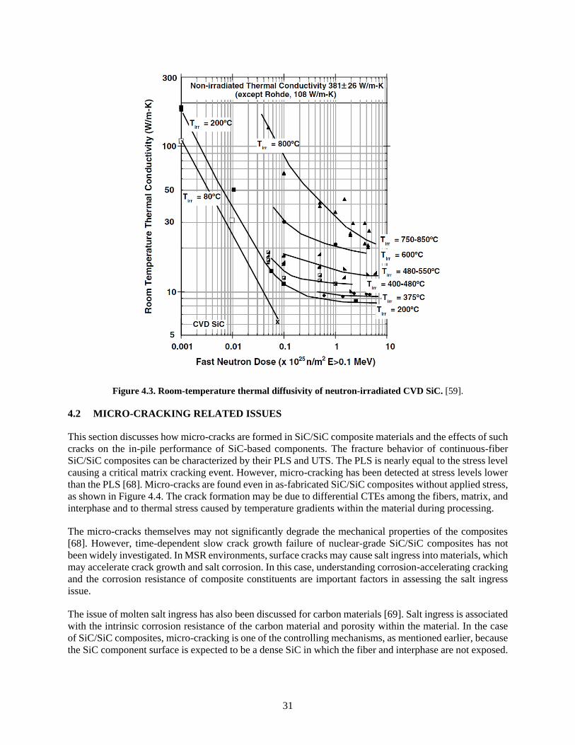
31
Figure 4.3. Room-temperature thermal diffusivity of neutron-irradiated CVD SiC. [59].
4.2 MICRO-CRACKING RELATED ISSUES
This section discusses how micro-cracks are formed in SiC/SiC composite materials and the effects of such
cracks on the in-pile performance of SiC-based components. The fracture behavior of continuous-fiber
SiC/SiC composites can be characterized by their PLS and UTS. The PLS is nearly equal to the stress level
causing a critical matrix cracking event. However, micro-cracking has been detected at stress levels lower
than the PLS [68]. Micro-cracks are found even in as-fabricated SiC/SiC composites without applied stress,
as shown in Figure 4.4. The crack formation may be due to differential CTEs among the fibers, matrix, and
interphase and to thermal stress caused by temperature gradients within the material during processing.
The micro-cracks themselves may not significantly degrade the mechanical properties of the composites
[68]. However, time-dependent slow crack growth failure of nuclear-grade SiC/SiC composites has not
been widely investigated. In MSR environments, surface cracks may cause salt ingress into materials, which
may accelerate crack growth and salt corrosion. In this case, understanding corrosion-accelerating cracking
and the corrosion resistance of composite constituents are important factors in assessing the salt ingress
issue.
The issue of molten salt ingress has also been discussed for carbon materials [69]. Salt ingress is associated
with the intrinsic corrosion resistance of the carbon material and porosity within the material. In the case
of SiC/SiC composites, micro-cracking is one of the controlling mechanisms, as mentioned earlier, because
the SiC component surface is expected to be a dense SiC in which the fiber and interphase are not exposed.

32
Figure 4.4. Micro-cracks found in as-fabricated CVI SiC/SiC composite. [61]
4.3 TECHNOLOGY GAPS IN THE PHYSICAL/MECHANICAL PROPERTIES AND
RADIATION EFFECTS
SiC/SiC composites are now being developed as engineering materials for nuclear applications, since much
early research in laboratory-grade materials has defined the material behavior and identified areas for
improvement and in-depth evaluation. Therefore, key future research areas will be related to engineering
issues. One of the technology gaps is assessment of material lifetime based on creep, fatigue, and corrosion.
For MSR applications, slow crack growth under salt corrosion environments is a critical feasibility issue
that has been insufficiently explored. For the issue of micro-cracking, statistical assessment of cracking
probability, understanding of the nature of cracks under different loading and corrosion conditions, and
establishment of test procedures to investigate slow crack growth are important areas of research.
Comprehensive studies of microcracking issues should provide criteria for failure of SiC/SiC composites
due to slow crack growth in MSRs.
In addition to those engineering issues, fundamental research is needed to address several issues. One of
the major areas is a more complete understanding of irradiation effects. Material degradation due to high-
dose neutron irradiation is a critical feasibility issue when the application temperature is relatively low and
neutron dose is high. SiC/SiC composites resistant to high-dose irradiation will offer a competitive
advantage if it is demonstrated that the core components can last substantially longer in their operating
environments. As a result of the recent findings of degradation of PyC interphases and Hi-Nicalon Type S
fibers at high doses [62, 65], it is necessary to optimize fiber/matrix interface design and materials for MSR
applications. The synergy between neutron irradiation and environmental effects, including salt corrosion
and applied stress/thermal stress, also needs be addressed.
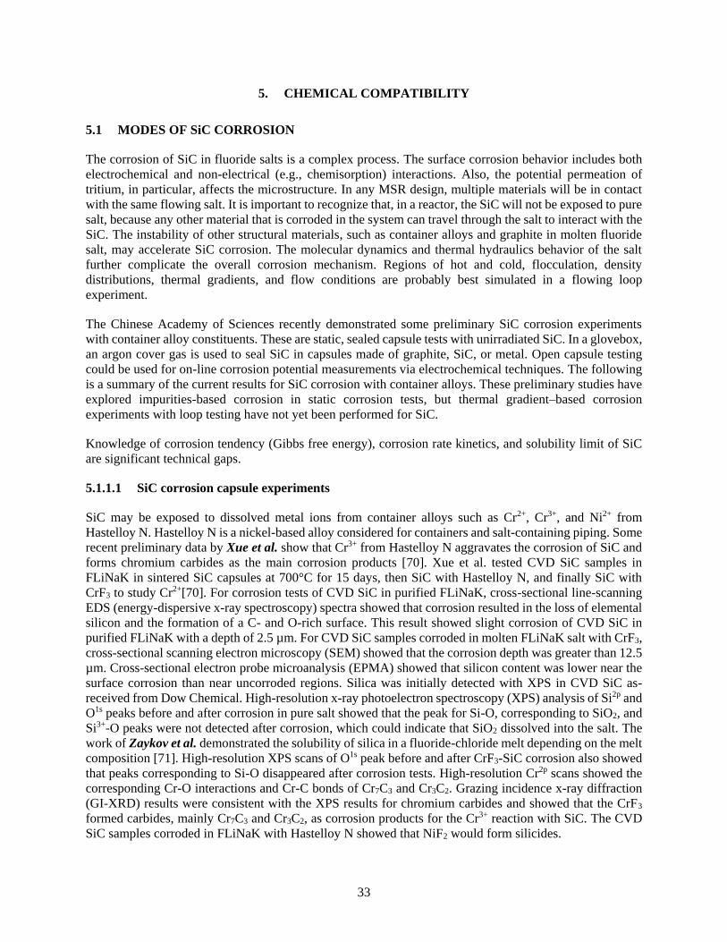
33
5. CHEMICAL COMPATIBILITY
5.1 MODES OF SiC CORROSION
The corrosion of SiC in fluoride salts is a complex process. The surface corrosion behavior includes both
electrochemical and non-electrical (e.g., chemisorption) interactions. Also, the potential permeation of
tritium, in particular, affects the microstructure. In any MSR design, multiple materials will be in contact
with the same flowing salt. It is important to recognize that, in a reactor, the SiC will not be exposed to pure
salt, because any other material that is corroded in the system can travel through the salt to interact with the
SiC. The instability of other structural materials, such as container alloys and graphite in molten fluoride
salt, may accelerate SiC corrosion. The molecular dynamics and thermal hydraulics behavior of the salt
further complicate the overall corrosion mechanism. Regions of hot and cold, flocculation, density
distributions, thermal gradients, and flow conditions are probably best simulated in a flowing loop
experiment.
The Chinese Academy of Sciences recently demonstrated some preliminary SiC corrosion experiments
with container alloy constituents. These are static, sealed capsule tests with unirradiated SiC. In a glovebox,
an argon cover gas is used to seal SiC in capsules made of graphite, SiC, or metal. Open capsule testing
could be used for on-line corrosion potential measurements via electrochemical techniques. The following
is a summary of the current results for SiC corrosion with container alloys. These preliminary studies have
explored impurities-based corrosion in static corrosion tests, but thermal gradient–based corrosion
experiments with loop testing have not yet been performed for SiC.
Knowledge of corrosion tendency (Gibbs free energy), corrosion rate kinetics, and solubility limit of SiC
are significant technical gaps.
5.1.1.1 SiC corrosion capsule experiments
SiC may be exposed to dissolved metal ions from container alloys such as Cr2+, Cr3+, and Ni2+ from
Hastelloy N. Hastelloy N is a nickel-based alloy considered for containers and salt-containing piping. Some
recent preliminary data by Xue et al. show that Cr3+ from Hastelloy N aggravates the corrosion of SiC and
forms chromium carbides as the main corrosion products [70]. Xue et al. tested CVD SiC samples in
FLiNaK in sintered SiC capsules at 700°C for 15 days, then SiC with Hastelloy N, and finally SiC with
CrF3 to study Cr2+[70]. For corrosion tests of CVD SiC in purified FLiNaK, cross-sectional line-scanning
EDS (energy-dispersive x-ray spectroscopy) spectra showed that corrosion resulted in the loss of elemental
silicon and the formation of a C- and O-rich surface. This result showed slight corrosion of CVD SiC in
purified FLiNaK with a depth of 2.5 µm. For CVD SiC samples corroded in molten FLiNaK salt with CrF3,
cross-sectional scanning electron microscopy (SEM) showed that the corrosion depth was greater than 12.5
µm. Cross-sectional electron probe microanalysis (EPMA) showed that silicon content was lower near the
surface corrosion than near uncorroded regions. Silica was initially detected with XPS in CVD SiC as-
received from Dow Chemical. High-resolution x-ray photoelectron spectroscopy (XPS) analysis of Si2p and
O1s peaks before and after corrosion in pure salt showed that the peak for Si-O, corresponding to SiO2, and
Si3+-O peaks were not detected after corrosion, which could indicate that SiO2 dissolved into the salt. The
work of Zaykov et al. demonstrated the solubility of silica in a fluoride-chloride melt depending on the melt
composition [71]. High-resolution XPS scans of O1s peak before and after CrF3-SiC corrosion also showed
that peaks corresponding to Si-O disappeared after corrosion tests. High-resolution Cr2p scans showed the
corresponding Cr-O interactions and Cr-C bonds of Cr7C3 and Cr3C2. Grazing incidence x-ray diffraction
(GI-XRD) results were consistent with the XPS results for chromium carbides and showed that the CrF3
formed carbides, mainly Cr7C3 and Cr3C2, as corrosion products for the Cr3+ reaction with SiC. The CVD
SiC samples corroded in FLiNaK with Hastelloy N showed that NiF2 would form silicides.

34
Yang et al. studied the corrosion of SiC in FLiNaK at 700°C with added CrF2 and NiF2 in an SiC capsule
for 15 days and 45 days, respectively. Yang et al. showed that when Hastelloy N is corroded by molten salt
forming fluorides, such as NiF2, the alloy and its corrosion products can aggravate SiC corrosion, which
proceeds through silicide formation (Ni31Si12) [72]. They first looked at corrosion of SiC in pure FLiNaK.
Raman spectroscopy before and after corrosion of CVD SiC in pure FLiNaK at 700°C in 15 days showed
a disorder peak (D peak) and a graphitic peak (G peak) consistent with those of a graphite-rich layer. Then
they looked at Hastelloy N samples and SiC in the same SiC capsule in FLiNaK. The cross-sectional EDS
line-scan showed that Ni, Cr, Fe, and Mo diffuse outward to the alloy surface; but Fe and Mo accumulate
near the surface, while Ni and Cr dissolve into the salt. Glow discharge mass spectroscopy (GD-MS) of
FLiNaK after corrosion showed the silicon content in FLiNaK increased. To study Cr2+ effects on SiC
corrosion, CrF2 and SiC were immersed in FLiNaK in the same SiC capsule; for Ni2+ effects on SiC
corrosion, SiC was immersed in FLiNaK mixed with NiF2. The results showed that Cr3+ drives SiC
corrosion by forming chromium carbides and a graphitic carbon layer. Hastelloy N experienced chromium
corrosion, forming fluorides (CrxFy) that aggravate SiC corrosion by driving silicon out of SiC into the melt,
forming SiF62- [72]. Corroded regions were explored with XPS and GI-XRD patterns, which detected
Cr7C3 and Cr3C2. For Ni2+ corrosion, GI-XRD patterns revealed that the CVD SiC surface coating composed
of ß-SiC of about 50 µm disappeared after about 45 days, but the corrosion of simultaneously immersed
Hastelloy N and SiC were not as severe.
Nishimura et al. studied SiC compatibility in FLiBe using a nickel crucible and found a thick silicide layer
deposited on the surface of SiC. According to Nishimura et al., the silicide layer is Ni31Si12 that may be the
product of Ni and Ni2+ reaction with SiC [73]. The effect of corrosion product Cr2+ was studied in the same
way with SEM and GI-XRD. For the capsules with CrF2, GI-XRD detected a new film of Cr7C3; and for
capsules with Hastelloy N and SiC, GI-XRD showed the new film was Cr7C3, CrC, and Fe4C. Silicon was
detected in the salt with GD-MS, and the graphitic phases were attributed to the dissolution of silicon into
the salt melt.
Some preliminary data from Yang et al. showed that when Hastelloy N (a nickel-based superalloy) is
corroded by molten salt forming fluorides, such as NiF2, the alloy and its corrosion products can aggravate
SiC corrosion, which proceeds through silicide formation (NixSiy) [72]. Xue et al. showed that at 700°C for
400 hours, Hastelloy N experienced chromium corrosion, forming fluorides (CrxFy) that aggravated SiC
corrosion by driving silicon out of SiC into the melt, forming SiF62- and different stoichiometries [70].
5.1.1.2 Pourbaix diagrams
A Pourbaix diagram shows the possible stable phases in an aqueous electrochemical system by plotting the
potential for different redox states of an element as a function of pH, for instance. A Pourbaix diagram of
the SiC, metal, graphite interactions in FLiBe and subsequently for FliNaK would be two important research
milestones which have not been addressed. Corrosion potentials are redox potentials measured during
corrosion that can be used to create Pourbaix diagrams. The diagram summarizes the conditions of redox
potential and oxide concentration in which significant corrosion or precipitation can be avoided. Commonly
used for metals, Pourbaix diagrams show three regions: regions where corrosion may or may not occur.
Metals that are applied in structures and components are in the passive region.
Pourbaix diagrams are useful for predicting the spontaneous direction of electrochemical processes and
corrosion products based on the potential and pH that result in a low or severe corrosion attack [74]. The
example diagram, Figure 5.1, was constructed with the Gibbs free energy change, and the E-pH dependent
reactions were calculated using the Nernst equation. The vertical lines are independent of potential but
dependent on pH, with no electron transfer. The sloping lines give the redox potential of a solution in
equilibrium with hydrogen or oxygen, respectively. This equilibrium indicates electron transfer as well as
pH. The concentration of all metal ions is assumed to be 10-6 mol/L of solution, and at lower concentration,
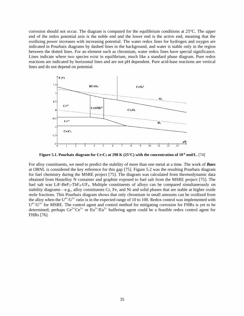
35
corrosion should not occur. The diagram is computed for the equilibrium conditions at 25°C. The upper
end of the redox potential axis is the noble end and the lower end is the active end, meaning that the
oxidizing power increases with increasing potential. The water redox lines for hydrogen and oxygen are
indicated in Pourbaix diagrams by dashed lines in the background, and water is stable only in the region
between the dotted lines. For an element such as chromium, water redox lines have special significance.
Lines indicate where two species exist in equilibrium, much like a standard phase diagram. Pure redox
reactions are indicated by horizontal lines and are not pH dependent. Pure acid-base reactions are vertical
lines and do not depend on potential.
Figure 5.1. Pourbaix diagram for Cr7C3 at 298 K (25°C) with the concentration of 10-6 mol/L. [74]
For alloy constituents, we need to predict the stability of more than one metal at a time. The work of Baes
at ORNL is considered the key reference for this gap [75]. Figure 5.2 was the resulting Pourbaix diagram
for fuel chemistry during the MSRE project [75]. The diagram was calculated from thermodynamic data
obtained from Hastelloy N container and graphite exposed to fuel salt from the MSRE project [75]. The
fuel salt was LiF-BeF2-ThF4-UF4. Multiple constituents of alloys can be compared simultaneously on
stability diagrams—e.g., alloy constituents Cr, Fe, and Ni and solid phases that are stable at higher oxide
mole fractions. This Pourbaix diagram shows that only chromium in small amounts can be oxidized from
the alloy when the U4+/U3+ ratio is in the expected range of 10 to 100. Redox control was implemented with
U4+/U3+ for MSRE. The control agent and control method for mitigating corrosion for FHRs is yet to be
determined; perhaps Ce2+/Ce3+ or Eu3+/Eu2+ buffering agent could be a feasible redox control agent for
FHRs [76].
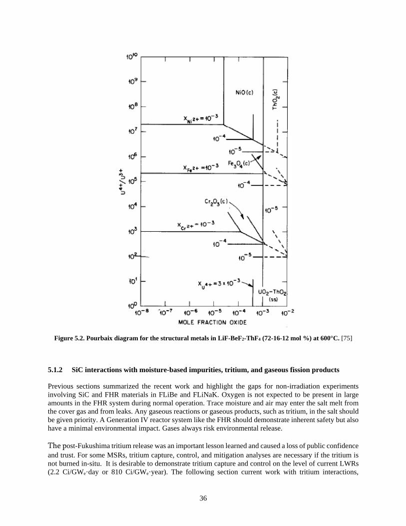
36
Figure 5.2. Pourbaix diagram for the structural metals in LiF-BeF2-ThF4 (72-16-12 mol %) at 600°C. [75]
5.1.2 SiC interactions with moisture-based impurities, tritium, and gaseous fission products
Previous sections summarized the recent work and highlight the gaps for non-irradiation experiments
involving SiC and FHR materials in FLiBe and FLiNaK. Oxygen is not expected to be present in large
amounts in the FHR system during normal operation. Trace moisture and air may enter the salt melt from
the cover gas and from leaks. Any gaseous reactions or gaseous products, such as tritium, in the salt should
be given priority. A Generation IV reactor system like the FHR should demonstrate inherent safety but also
have a minimal environmental impact. Gases always risk environmental release.
The post-Fukushima tritium release was an important lesson learned and caused a loss of public confidence
and trust. For some MSRs, tritium capture, control, and mitigation analyses are necessary if the tritium is
not burned in-situ. It is desirable to demonstrate tritium capture and control on the level of current LWRs
(2.2 Ci/GWe·day or 810 Ci/GWe·year). The following section current work with tritium interactions,

37
release, capture, and control are discussed along with SiC and tritium interactions to identify the key
research gaps.
The extensive research on fission product transport/retention in TRISO fuels for other reactor systems like
advanced gas-cooled reactors or even LFMSRs. It is important to recognize that for SiC materials in FHRs
intended for use in non-fuel assemblies and components, lack of knowledge regarding the effects of fission
product impurities in the salt reacting with SiC is also a significant gap.
5.1.2.1 SiC and intrinsic oxidants
Highly crystalline composites are desired because they have a stronger chemical bond between the Si and
C. Yang et al. showed that SiC variants with higher oxygen impurities are more corroded by FLiNaK than
are purified SiC variants. The purest SiC was corroded slightly by oxygen impurities in the FLiNaK. Single-
crystal SiC and very high-purity CVD SiC (0.999995 %) were only slightly corroded in FLiNaK at 700°C
for 10 and 45 days [77]. XPS elemental surface technique was used to detect oxygen and Si3+ oxidation
states on the corroded samples. Silicon was detected in the salt with Inductively Coupled Plasma Optical
Emission Spectrometry (ICP-OES). Oxygen contamination of FLiNaK probably aggravated the slight
corrosion of SiC. The oxidation of SiC is expected to increase with temperature but currently there is a lack
of experimental validation.
One potential fabrication constraint is the impurity content/purification of SiC, because oxygen
contamination during composite densification processes have shown to drive preferential oxidation in
molten fluoride salt. The normal levels of impurities circulating in the molten salt and the gases above the
salt are not well known. Another potential gap is the effect of SiC oxidation/SiC purity on the redox control.
Wang et al. showed that the corrosion of SiC composites accelerated with temperature but the interlayer
boundary in the SiC matrix was preferentially corroded because of higher intrinsic oxygen content [78].
The Si-O bond in the O-containing SiC phase was attacked by free F- anions at 800 to 1000°C for 500 hours
in the salt to form Si-F bonds (SiF6 decomposing to SiF4 that escapes the melt). The results tend to show
that oxygen in SiC accelerates the corrosion of SiC in fluoride salts. Corrosion would result from the loss
of silicon in SiC, with graphite as a reaction product [80]. EDS scans showed that oxygen content in
interlayer boundaries is slightly higher than in the matrix, probably because of the repetitive densification
process. The interlayer boundaries and then the matrix around the residual pores in fiber-reinforced
SiCf/SiC were corroded, and the corrosion was non-uniform. Micrographs showed exfoliation of the
composite surface. Gaps in the matrix probably resulted from selective corrosion of interlayer boundaries,
and the gaps in the matrix then increased the porosity in the composites. Wang et al. studied a CVI SiC
composite material. Unlike the corrosion in CVD SiC, non-uniform corrosion of CVI SiCf/SiC composites
in molten fluoride salt was observed.
A study at the University of Wisconsin–Madison showed that CVI-SiC lost more weight than CVD-SiC
when both were exposed to FLiBe at 700°C for 1000 hours continuously. Figure 5.3 shows the results of
these corrosion tests on several materials. These are preliminary studies and unpublished work.

38
Figure 5.3. Results of University of Wisconsin–Madison testing at 700°C for 1000 hours of various materials
in FLiBe for FHR. Vertical axis indicates mass loss with a net loss being negative. All test specimens were placed
in a graphite container except CVI-SiC and CVD SiC were placed in a graphite container [79].
The capsule material for the SiC samples were not specified in the above study.
5.1.2.2 Tritium interaction with SiC
Tritium control and capture is a major challenge for MSRs. In a recent study, the tritium production rates
were predicted for FHRs (Table 5.1).
Table 5.1. Tritium production rates by reactor compared with calculated values
for FHRs using TRIDENT. [80].
The main pathways for in-core tritium production are shown in the nuclear reactions in Eqs. (2) – (4) [80],
and the decay of 6He is shown in Eq. (5).
𝐿𝑖𝐹36 + 𝑛0
1 → 𝐻𝐹13 + 𝛼2
4 . (2)
𝐿𝑖𝐹37 + 𝑛0
1 → 𝐻𝐹 + 𝛼24 + 𝑛0
1 ′13 . (3)
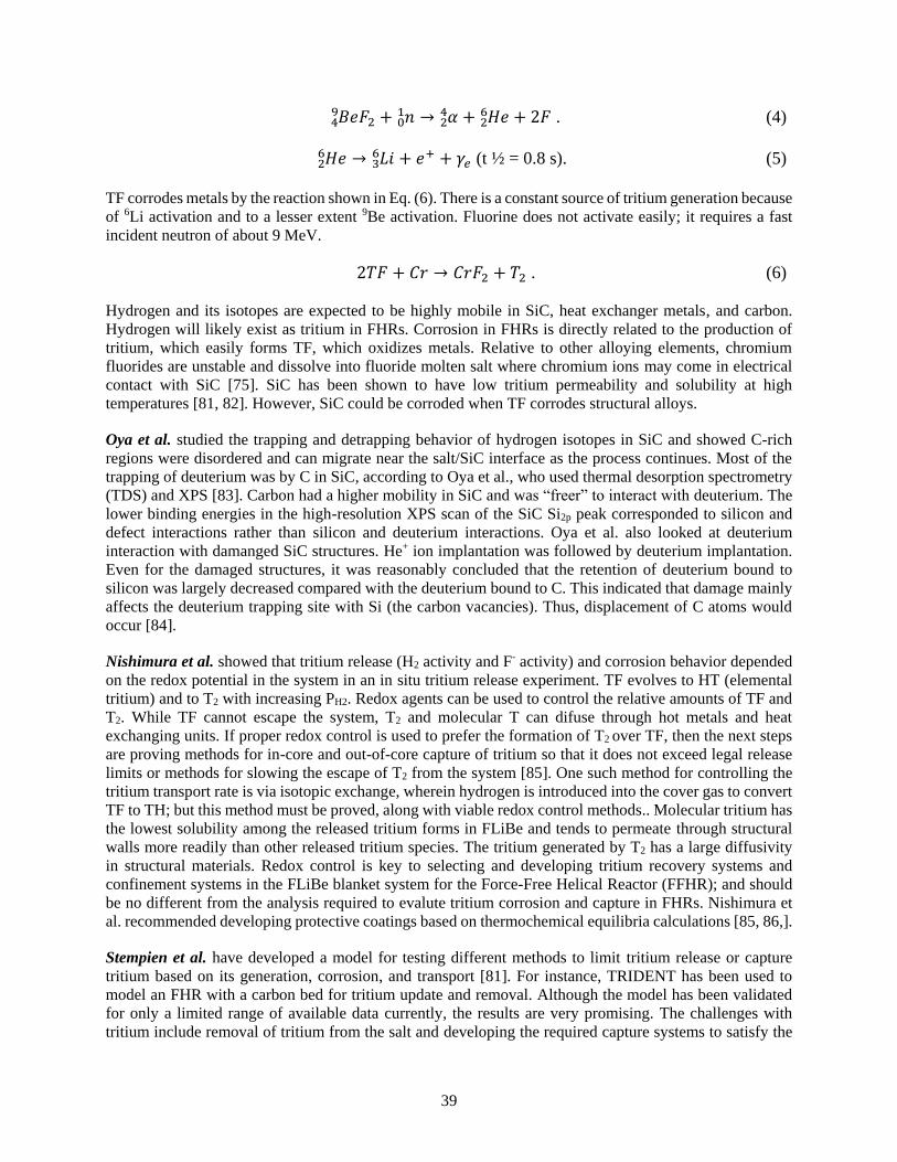
39
𝐵𝑒𝐹2 + 𝑛01 → 𝛼2
449 + 𝐻𝑒2
6 + 2𝐹 . (4)
𝐻𝑒26 → 𝐿𝑖 + 𝑒+ + 𝛾𝑒3
6 (t ½ = 0.8 s). (5)
TF corrodes metals by the reaction shown in Eq. (6). There is a constant source of tritium generation because
of 6Li activation and to a lesser extent 9Be activation. Fluorine does not activate easily; it requires a fast
incident neutron of about 9 MeV.
2𝑇𝐹 + 𝐶𝑟 → 𝐶𝑟𝐹2 + 𝑇2 . (6)
Hydrogen and its isotopes are expected to be highly mobile in SiC, heat exchanger metals, and carbon.
Hydrogen will likely exist as tritium in FHRs. Corrosion in FHRs is directly related to the production of
tritium, which easily forms TF, which oxidizes metals. Relative to other alloying elements, chromium
fluorides are unstable and dissolve into fluoride molten salt where chromium ions may come in electrical
contact with SiC [75]. SiC has been shown to have low tritium permeability and solubility at high
temperatures [81, 82]. However, SiC could be corroded when TF corrodes structural alloys.
Oya et al. studied the trapping and detrapping behavior of hydrogen isotopes in SiC and showed C-rich
regions were disordered and can migrate near the salt/SiC interface as the process continues. Most of the
trapping of deuterium was by C in SiC, according to Oya et al., who used thermal desorption spectrometry
(TDS) and XPS [83]. Carbon had a higher mobility in SiC and was “freer” to interact with deuterium. The
lower binding energies in the high-resolution XPS scan of the SiC Si2p peak corresponded to silicon and
defect interactions rather than silicon and deuterium interactions. Oya et al. also looked at deuterium
interaction with damanged SiC structures. He+ ion implantation was followed by deuterium implantation.
Even for the damaged structures, it was reasonably concluded that the retention of deuterium bound to
silicon was largely decreased compared with the deuterium bound to C. This indicated that damage mainly
affects the deuterium trapping site with Si (the carbon vacancies). Thus, displacement of C atoms would
occur [84].
Nishimura et al. showed that tritium release (H2 activity and F- activity) and corrosion behavior depended
on the redox potential in the system in an in situ tritium release experiment. TF evolves to HT (elemental
tritium) and to T2 with increasing PH2. Redox agents can be used to control the relative amounts of TF and
T2. While TF cannot escape the system, T2 and molecular T can difuse through hot metals and heat
exchanging units. If proper redox control is used to prefer the formation of T2 over TF, then the next steps
are proving methods for in-core and out-of-core capture of tritium so that it does not exceed legal release
limits or methods for slowing the escape of T2 from the system [85]. One such method for controlling the
tritium transport rate is via isotopic exchange, wherein hydrogen is introduced into the cover gas to convert
TF to TH; but this method must be proved, along with viable redox control methods.. Molecular tritium has
the lowest solubility among the released tritium forms in FLiBe and tends to permeate through structural
walls more readily than other released tritium species. The tritium generated by T2 has a large diffusivity
in structural materials. Redox control is key to selecting and developing tritium recovery systems and
confinement systems in the FLiBe blanket system for the Force-Free Helical Reactor (FFHR); and should
be no different from the analysis required to evalute tritium corrosion and capture in FHRs. Nishimura et
al. recommended developing protective coatings based on thermochemical equilibria calculations [85, 86,].
Stempien et al. have developed a model for testing different methods to limit tritium release or capture
tritium based on its generation, corrosion, and transport [81]. For instance, TRIDENT has been used to
model an FHR with a carbon bed for tritium update and removal. Although the model has been validated
for only a limited range of available data currently, the results are very promising. The challenges with
tritium include removal of tritium from the salt and developing the required capture systems to satisfy the

40
legally allowable tritium release limits. The trade-off is between high-efficiency removal of tritium from
the salt and effective barriers to slow tritium transport through metals. Workshops have been held to
coordinate research efforts, and a summary of the workshop results is available from Forseberg et al. [87,
88]. Calderoni et al. have assessed tritium permeation in the salt [89].
Tritium will likely exist as some ratio of T2 /TF in the FHR system. TF can corrode container alloys and
continually introduce metal impurities into the salt that attack SiC. Molecular T2 can dissociate and atomic
tritium can permeate SiC and become trapped in vacancy defects of irradiated SiC. The trapping behavior
of tritium in structural SiC is very undesirable because it affects tritium capture and mitigation in the FHR
system, and it is not well known how tritium interactions with radiation defects can affect the
microstructural properties of SiC that we value.
5.2 THERMOPHYSICAL PROPERTIES OF SALTS
Knowledge of salt chemistry is key to understanding the corrosion environment. The salt is the most
dynamic component of the system. The molecular dynamics, chemical inventory, and
flocculation/dispersion behavior (the ability of particles, atoms and molecules in the salt to interact with
one another) of just the FLiBe itself are of great interest.
There is a considerable knowledge basis for the thermophysical properties of salts that have been optimized
for use with nuclear fuels and nuclear materials. Although FLiBe and FLiNaK are two strongly preferred
basic fluoride salts for FHRs, other coolant salts have been examined in light of the drawbacks of Hastelloy
N corrosion in FLiBe discovered during the MSRE in the 1960s [90]. FLiBe is a preferred salt with good
neutronic and thermal-hydraulic. For coolant salts, an important consideration is the salt melting point.
The salts are used in mixtures to reduce melting points and importantly. The salts are used in mixtures to
reduce melting points and, importantly, lithium lowers melting points and also improves the heat transfer
characteristics of the mixture. The main disadvantage to the 6Li in the salt is tritium production, as shown
in Equation (1)-(4).
Besides the fluoride salts, chloride salts are also suggested for fast breeder LFMSRs but not for thermal
spectrum FHRs. They have a higher thermal neutron absorption cross-section than fluoride salts, but they
also generate unfavorable Cl36 isotope (ßmax = 0.71 MeV) [91]. Magnesium chloride salts have been
considered for the intermediate salt loop and for the DRACS secondary loop for a PB-FHR [92]. Savannah
River researchers looked at MgCl2-KCl to study and monitor salt potential with magnesium when it
interacts with Haynes 230. They showed some preliminary results that suggest magnesium inhibits
corrosion when added, evinced by a lower redox potential.
The choice of salt for FHRs involves many aspects, but the base case considers the two salts that have the
better thermal and neutronic properties, not necessarily the best chemical properties. The following section
includes a survey of several candidate salts other than FLiBe and FLiNaK; their benefits are discussed and
their chemical compatibility with SiC is considered. Each candidate salt has a set of benefits and detriments.
The tritium and fission products transport in FLiBe for FHRs is a significant knowledge gap. The tritium
transport behavior in the salt must be studied with SiC corrosion.
5.2.1 Physical Chemistry of Candidate Coolant Salts
The proposed coolant salts are mixtures with different salt components mixed to form either a binary (X-
Y) or tertiary (X-Y-Z) multi-component system. The mixtures are denoted with molar percentages of each
component and have a lower melting point than each individual component salt. For FHRs, the primary
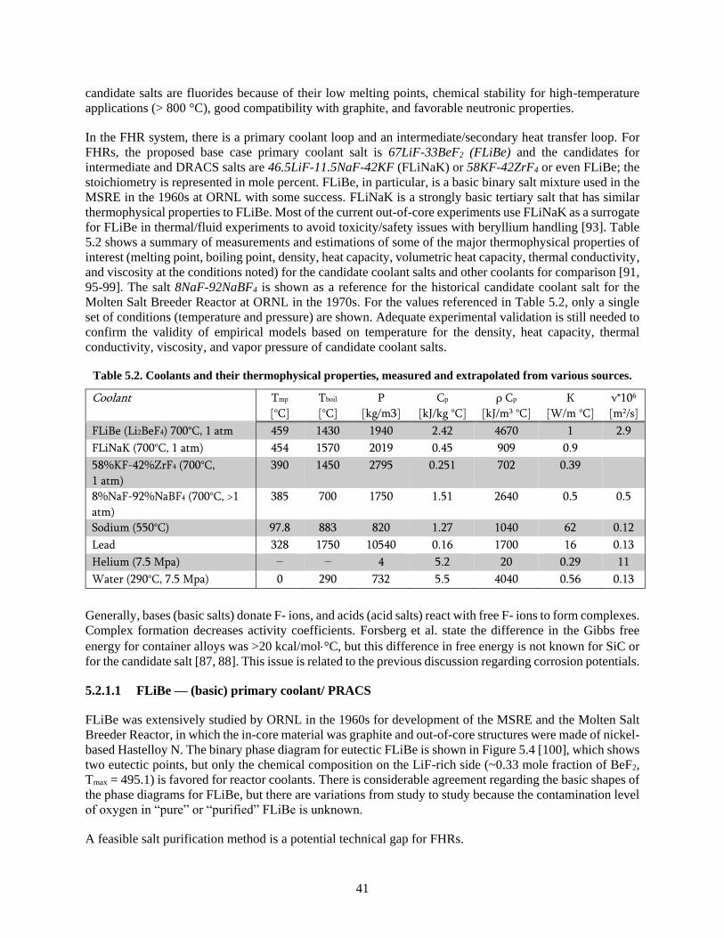
41
candidate salts are fluorides because of their low melting points, chemical stability for high-temperature
applications (> 800 °C), good compatibility with graphite, and favorable neutronic properties.
In the FHR system, there is a primary coolant loop and an intermediate/secondary heat transfer loop. For
FHRs, the proposed base case primary coolant salt is 67LiF-33BeF2 (FLiBe) and the candidates for
intermediate and DRACS salts are 46.5LiF-11.5NaF-42KF (FLiNaK) or 58KF-42ZrF4 or even FLiBe; the
stoichiometry is represented in mole percent. FLiBe, in particular, is a basic binary salt mixture used in the
MSRE in the 1960s at ORNL with some success. FLiNaK is a strongly basic tertiary salt that has similar
thermophysical properties to FLiBe. Most of the current out-of-core experiments use FLiNaK as a surrogate
for FLiBe in thermal/fluid experiments to avoid toxicity/safety issues with beryllium handling [93]. Table
5.2 shows a summary of measurements and estimations of some of the major thermophysical properties of
interest (melting point, boiling point, density, heat capacity, volumetric heat capacity, thermal conductivity,
and viscosity at the conditions noted) for the candidate coolant salts and other coolants for comparison [91,
95-99]. The salt 8NaF-92NaBF4 is shown as a reference for the historical candidate coolant salt for the
Molten Salt Breeder Reactor at ORNL in the 1970s. For the values referenced in Table 5.2, only a single
set of conditions (temperature and pressure) are shown. Adequate experimental validation is still needed to
confirm the validity of empirical models based on temperature for the density, heat capacity, thermal
conductivity, viscosity, and vapor pressure of candidate coolant salts.
Table 5.2. Coolants and their thermophysical properties, measured and extrapolated from various sources.
Coolant Tmp
[°C]
Tboil
[°C]
Ρ
[kg/m3]
Cp
[kJ/kg °C]
ρ Cp
[kJ/m3 °C]
К
[W/m °C]
ν*106
[m2/s]
FLiBe (Li2BeF4) 700°C, 1 atm 459 1430 1940 2.42 4670 1 2.9
FLiNaK (700°C, 1 atm) 454 1570 2019 0.45 909 0.9
58%KF-42%ZrF4 (700°C,
1 atm)
390 1450 2795 0.251 702 0.39
8%NaF-92%NaBF4 (700°C, >1
atm)
385 700 1750 1.51 2640 0.5 0.5
Sodium (550°C) 97.8 883 820 1.27 1040 62 0.12
Lead 328 1750 10540 0.16 1700 16 0.13
Helium (7.5 Mpa) – – 4 5.2 20 0.29 11
Water (290°C, 7.5 Mpa) 0 290 732 5.5 4040 0.56 0.13
Generally, bases (basic salts) donate F- ions, and acids (acid salts) react with free F- ions to form complexes.
Complex formation decreases activity coefficients. Forsberg et al. state the difference in the Gibbs free
energy for container alloys was >20 kcal/mol°C, but this difference in free energy is not known for SiC or
for the candidate salt [87, 88]. This issue is related to the previous discussion regarding corrosion potentials.
5.2.1.1 FLiBe — (basic) primary coolant/ PRACS
FLiBe was extensively studied by ORNL in the 1960s for development of the MSRE and the Molten Salt
Breeder Reactor, in which the in-core material was graphite and out-of-core structures were made of nickel-
based Hastelloy N. The binary phase diagram for eutectic FLiBe is shown in Figure 5.4 [100], which shows
two eutectic points, but only the chemical composition on the LiF-rich side (~0.33 mole fraction of BeF2,
Tmax = 495.1) is favored for reactor coolants. There is considerable agreement regarding the basic shapes of
the phase diagrams for FLiBe, but there are variations from study to study because the contamination level
of oxygen in “pure” or “purified” FLiBe is unknown.
A feasible salt purification method is a potential technical gap for FHRs.
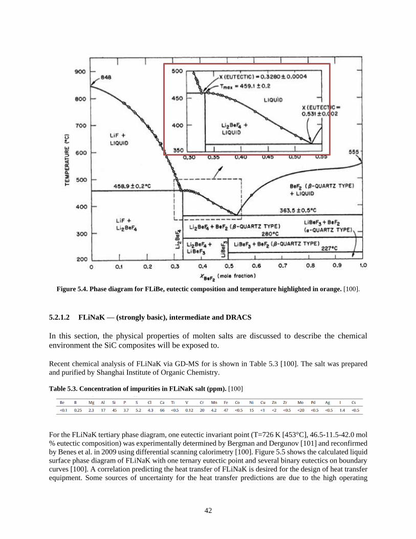
42
Figure 5.4. Phase diagram for FLiBe, eutectic composition and temperature highlighted in orange. [100].
5.2.1.2 FLiNaK — (strongly basic), intermediate and DRACS
In this section, the physical properties of molten salts are discussed to describe the chemical
environment the SiC composites will be exposed to.
Recent chemical analysis of FLiNaK via GD-MS for is shown in Table 5.3 [100]. The salt was prepared
and purified by Shanghai Institute of Organic Chemistry.
Table 5.3. Concentration of impurities in FLiNaK salt (ppm). [100]
For the FLiNaK tertiary phase diagram, one eutectic invariant point (T=726 K [453°C], 46.5-11.5-42.0 mol
% eutectic composition) was experimentally determined by Bergman and Dergunov [101] and reconfirmed
by Benes et al. in 2009 using differential scanning calorimetry [100]. Figure 5.5 shows the calculated liquid
surface phase diagram of FLiNaK with one ternary eutectic point and several binary eutectics on boundary
curves [100]. A correlation predicting the heat transfer of FLiNaK is desired for the design of heat transfer
equipment. Some sources of uncertainty for the heat transfer predictions are due to the high operating
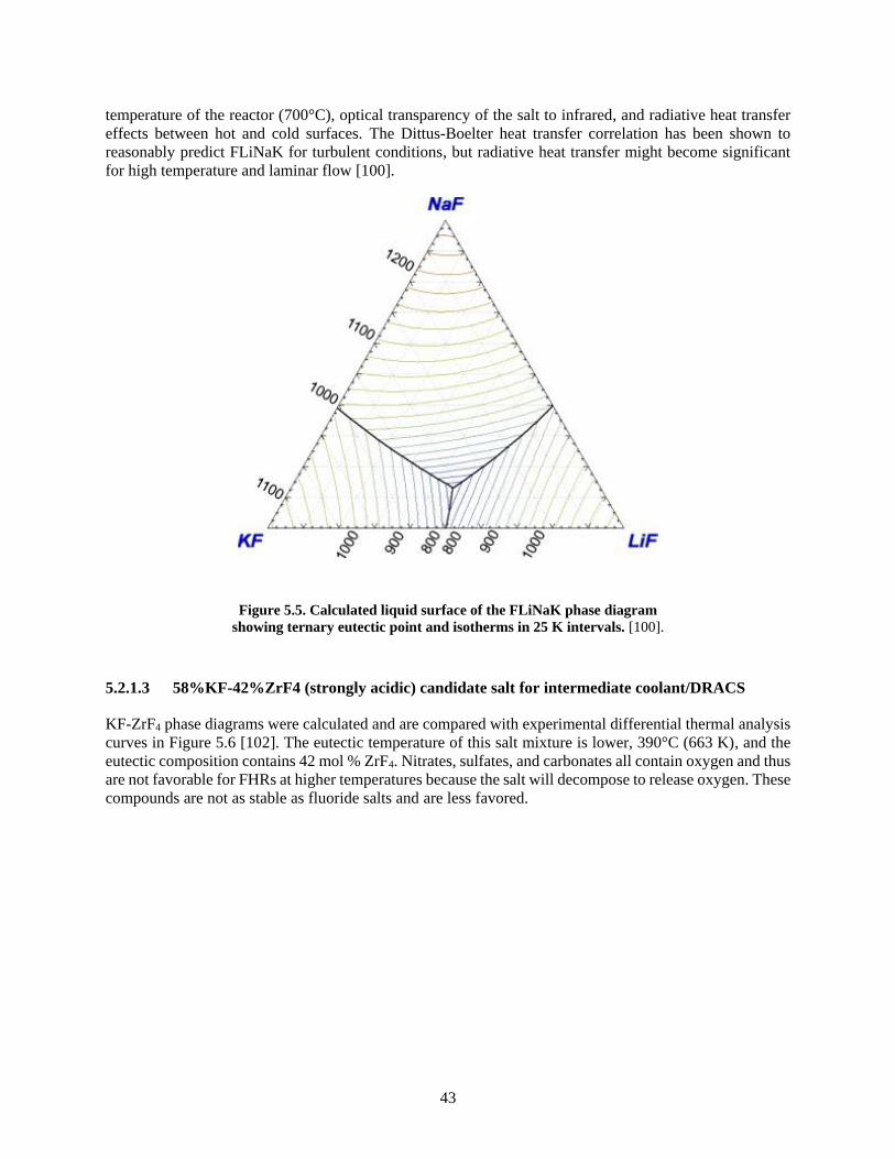
43
temperature of the reactor (700°C), optical transparency of the salt to infrared, and radiative heat transfer
effects between hot and cold surfaces. The Dittus-Boelter heat transfer correlation has been shown to
reasonably predict FLiNaK for turbulent conditions, but radiative heat transfer might become significant
for high temperature and laminar flow [100].
Figure 5.5. Calculated liquid surface of the FLiNaK phase diagram
showing ternary eutectic point and isotherms in 25 K intervals. [100].
5.2.1.3 58%KF-42%ZrF4 (strongly acidic) candidate salt for intermediate coolant/DRACS
KF-ZrF4 phase diagrams were calculated and are compared with experimental differential thermal analysis
curves in Figure 5.6 [102]. The eutectic temperature of this salt mixture is lower, 390°C (663 K), and the
eutectic composition contains 42 mol % ZrF4. Nitrates, sulfates, and carbonates all contain oxygen and thus
are not favorable for FHRs at higher temperatures because the salt will decompose to release oxygen. These
compounds are not as stable as fluoride salts and are less favored.
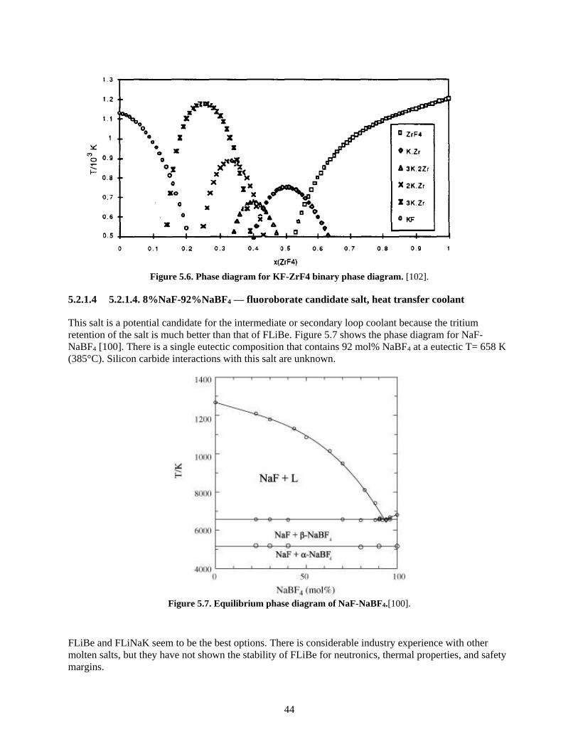
44
Figure 5.6. Phase diagram for KF-ZrF4 binary phase diagram. [102].
5.2.1.4 5.2.1.4. 8%NaF-92%NaBF4 — fluoroborate candidate salt, heat transfer coolant
This salt is a potential candidate for the intermediate or secondary loop coolant because the tritium
retention of the salt is much better than that of FLiBe. Figure 5.7 shows the phase diagram for NaF-
NaBF4 [100]. There is a single eutectic composition that contains 92 mol% NaBF4 at a eutectic T= 658 K
(385°C). Silicon carbide interactions with this salt are unknown.
Figure 5.7. Equilibrium phase diagram of NaF-NaBF4.[100].
FLiBe and FLiNaK seem to be the best options. There is considerable industry experience with other
molten salts, but they have not shown the stability of FLiBe for neutronics, thermal properties, and safety
margins.
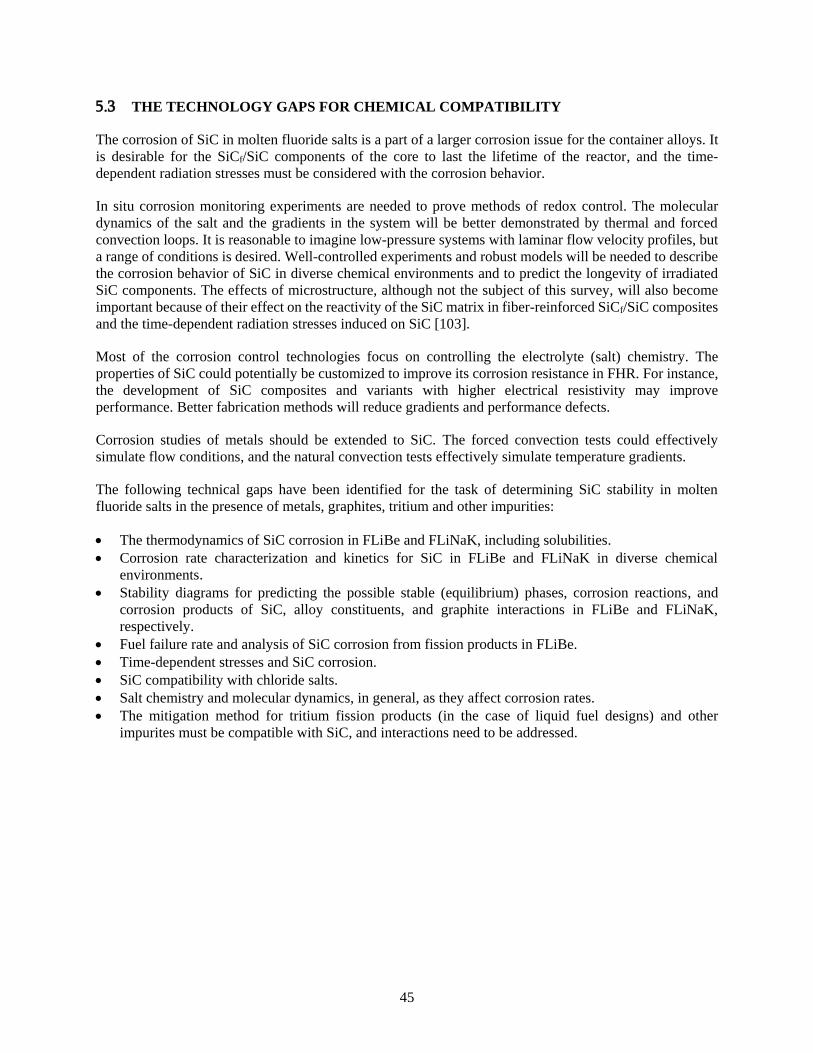
45
5.3 THE TECHNOLOGY GAPS FOR CHEMICAL COMPATIBILITY
The corrosion of SiC in molten fluoride salts is a part of a larger corrosion issue for the container alloys. It
is desirable for the SiCf/SiC components of the core to last the lifetime of the reactor, and the time-
dependent radiation stresses must be considered with the corrosion behavior.
In situ corrosion monitoring experiments are needed to prove methods of redox control. The molecular
dynamics of the salt and the gradients in the system will be better demonstrated by thermal and forced
convection loops. It is reasonable to imagine low-pressure systems with laminar flow velocity profiles, but
a range of conditions is desired. Well-controlled experiments and robust models will be needed to describe
the corrosion behavior of SiC in diverse chemical environments and to predict the longevity of irradiated
SiC components. The effects of microstructure, although not the subject of this survey, will also become
important because of their effect on the reactivity of the SiC matrix in fiber-reinforced SiCf/SiC composites
and the time-dependent radiation stresses induced on SiC [103].
Most of the corrosion control technologies focus on controlling the electrolyte (salt) chemistry. The
properties of SiC could potentially be customized to improve its corrosion resistance in FHR. For instance,
the development of SiC composites and variants with higher electrical resistivity may improve
performance. Better fabrication methods will reduce gradients and performance defects.
Corrosion studies of metals should be extended to SiC. The forced convection tests could effectively
simulate flow conditions, and the natural convection tests effectively simulate temperature gradients.
The following technical gaps have been identified for the task of determining SiC stability in molten
fluoride salts in the presence of metals, graphites, tritium and other impurities:
• The thermodynamics of SiC corrosion in FLiBe and FLiNaK, including solubilities.
• Corrosion rate characterization and kinetics for SiC in FLiBe and FLiNaK in diverse chemical
environments.
• Stability diagrams for predicting the possible stable (equilibrium) phases, corrosion reactions, and
corrosion products of SiC, alloy constituents, and graphite interactions in FLiBe and FLiNaK,
respectively.
• Fuel failure rate and analysis of SiC corrosion from fission products in FLiBe.
• Time-dependent stresses and SiC corrosion.
• SiC compatibility with chloride salts.
• Salt chemistry and molecular dynamics, in general, as they affect corrosion rates.
• The mitigation method for tritium fission products (in the case of liquid fuel designs) and other
impurites must be compatible with SiC, and interactions need to be addressed.
46
6. CONCLUSION AND PATH FORWARD
This report highlights the technology gaps that exist for SiCf/SiC composite materials if they are to be used
in MSRs. It focuses mainly on FHR technology with some reference to LFMSRs. It addresses four areas of
major concern: design methods and rules required for licensing, materials and manufacturing constraints
and techniques, properties and radiation effects of irradiated materials, and chemical compatibility.
The design code and rules are near completion and will be adopted within the ASME BPVC Section III
Division 5 within the near future. The code needs to be supported with a technical basis document that
contains benchmarking data for typical designs. Continuation of additional test standard development is
suggested, more specifically for the MSR environment, followed by round robin testing once standards are
developed.
The fabrication of large and complex-shape components made of nuclear-grade SiCf/SiC composites is
currently practiced and may be beneficial for some MSR applications. Although processing elements and
joining/integration technologies are available, demonstration of component fabrication will be required.
Joining and integration technologies are available for fabrication of SiC-based components. Silicon
carbide–based joining layers have been demonstrated to retain strength following neutron irradiation. It is
suggested that further investigation be conducted by exposing the joints to salt. Dissimilar material joints
are more complex and need additional development if they should prove to be desirable for MSR
technology.
The physical and mechanical property evaluation found that material degradation due to high-dose neutron
irradiation is a critical feasibility issue when the application temperature is relatively low and neutron dose
is high. A major technology gap is a complete understanding of the irradiation effects. SiC/SiC composites
resistant to high-dose irradiation will offer a competitive advantage if it is demonstrated that the core
components can last substantially longer in their operating environments. More data are required to address
the synergy of neutron irradiation and the environmental effects, including salt corrosion and applied
stress/thermal stress.
Additionally, slow crack growth in salt corrosion environments is a critical feasibility issue that has been
insufficiently explored. Statistical assessment of cracking probability, understanding of the nature of cracks
under different loading and corrosion conditions, and establishment of testing procedures to investigate
slow crack growth are important studies to be conducted. Comprehensive studies of the microcracking
issues should provide criteria for failure of SiCf/SiC composites due to slow crack growth in MSRs.
Silicon carbide components will be exposed to diverse chemical environments. A preferred salt for the
primary coolant system is FLiBe. It is also a candidate for the intermediate loop system as is FLiNaK.
Limited data exist for SiC behavior in chloride salts. Further experiments are needed to determine if SiC
could be used in chloride salt MSRs.
Silicon carbide exhibits wettability and chemical reactivity with metals but is generally stable in molten
fluoride salts so long as the salt purity is maintained. Thermal loop testing of SiC has not been performed;
but it is believed that thermal gradients could sustain corrosion in FHRs, whereas impurities-based
corrosion is limited by solubilities and concentration. At controlled concentration levels, the corrosion of
SiC in molten fluoride salt depends directly on the redox condition of the salt and the various methods used
to mitigate impurities and tritium.
47
Tritium is a concern because the corrosion behavior of SiC is directly related to tritium capture.
Furthermore, hydrogen and its isotopes are highly mobile in SiC. For the safe control of the tritium produced
in the reactor, its retention and diffusion through the reactor materials must be known. The solubility of
tritium and lattice diffusion behavior in irradiated SiC should be studied in conjunction with surface
corrosion.
Corrosion testing can consist of static experiments in sealed capsules or dynamic loop experiments (thermal
or forced convection). The static tests have demonstrated their practicality but are prone to errors, and
oxygen in leakage could show a much higher corrosion rate than is actually caused by the pure salt. Loop
testing of SiC has not yet been performed but would be beneficial to more accurately simulate reactor
conditions.
Silicon carbide–based materials have many inherent properties that make them promising candidates for
use in MSRs. However, before deploying a SiC/SiC composite in a MSR, there are several issues that must
be resolved, and some of them are specific to the conditions of individual reactor designs. Throughout the
text, several technology gaps are identified along with initial recommendations for how to address the gaps.
The next step is to develop a detailed roadmap to show the development path of SiC composites for MSR
applications.
48
7. REFERENCES
7.1 SECTION 1
[1] H.D. Gougar et al., Assessment of the Technical Maturity of Generation IV Concepts for Test or
Demonstration Reactor Concepts, INL/EXT 15-36427 Rev 2, Idaho National Laboratory, Idaho
Falls, ID, October 2015.
[2] A. Qualls et al., Preconceptual design of a fluoride high temperature salt-cooled engineering
demonstration reactor: Motivation and overview,” Annals of Nuclear Energy 107 (2017) p.144-
155.
7.2 SECTION 2
[3] C.W. Forsberg et al., “Tritium control and capture in salt-cooled fission and fusion reactors,”
Fusion Science and Technology 71(4) (2017) 584-589.
[4] C.W. Forsberg, et al., “Tritium control and capture in salt-cooled fission and fusion reactors:
Status, challenges, and path forward,” Nuclear Technology 197(2) (2017) 119-139.
[5] D.E. Holcomb et al., Fluoride Salt-Cooled High-Temperature Reactor Technology
Development and Demonstration Roadmap, ORNL/TM-2013-401, Oak Ridge National
Laboratory, September 2013.
[6] C. Andreades et al., Technical Description of the ‘Mark 1’ Pebble-Bed Fluoride-Salt-Cooled
High Temperature Reactor (PB-FHR) Power Plant, UCBTH-14-002, Department of Nuclear
Engineering, University of California, Berkley, CA, September 2014.
[7] Xingtai Zhou, “Current Status of TMSR and the Consideration of Its Materials,” NEUP
Integrated Research Project Workshop, Madison, WI, Aug. 2012.
[8] Lance K. Kim, “Molten Salt Reactor Technical Working Group Licensing Perspective,”
GAIN Fuel Safety Research Workshop, Idaho Falls, ID. May 2017
[9] Hongjie Xu, “Status and Perspective of TMSR in China,” PSI, Switzerland, January 2017.
[10] J. Serp et al., “The molten salt reactor (MSR) in generation IV: Overview and perspectives,”
Progress in Nuclear Energy 77 (2014) p308-319.
[11] International Atomic Energy Agency, Advances in Small Modular Reactor Technology
Developments, A supplement to IAEA Advanced Reactors Information Systems (ARIS), 2016
Edition, http://aris.iaea.org.
[12] Michael J. Eades et al., “The influence of Xe-135m on steady-state xenon worth in thermal
molten salt reactors,” Progress in Nuclear Energy 93 (2016) p397-405.
[13] Per Peterson, “Overview of FHR-Specific Primary and Intermediate Loop Environments,”
NEUP Integrated Research Project Workshop, Madison, WI, Aug. 2012.
[14] Transatomic, Technical White Paper, November 2016 V2.1, ww.transatomicpower.com/wp-
content/uploads/2015, March 2018.
[15] Fluoride-Salt-Cooled, High-Temperature Reactor (FHR) Development Roadmap and Test
Reactor Performance Requirements White Paper, UCBTH-12-004, Massachusetts Institute of
Technology, June 2013..
[16] Transatomic Power, Technical White Paper, March 2014
V1.01,www.large.stanford.edu/courses/2015/ph241/khalaf1/docs/TAP_White_Paper.pdf,
accessed May 2018.

49
[17] D. Koch, “Microstructural Modeling and Thermomechanical Properties,” Ceramic Matrix
Composites—Fiber Reinforced Ceramics and Their Application, Ed. W. Krenkel, Wiley-
Koch, 2008, p. 231-259
[18] S.R. Greene et al., Pre-Conceptual Design of a Fluoride-Salt-Cooled Small Modular
Advanced High-Temperature Reactor (Sm-AHTR), ORNL-TM-2010/199, Oak Ridge National
Laboratory, December 2010.
[19] A. Qualls et al., Fluoride Salt-Cooled High Temperature Demonstration Reactor Point
Design, ORNL/TM-2016/85, Oak Ridge National Laboratory, Oak Ridge, TN, February 2016.
[20] D.E. Holcomb, D. Ilas, V.K. Varma, A.T. Cisneros, R.P. Kelly, J.C. Gehin, Core and
Refueling Design Studies for the Advanced High Temperature Reactor, ORNL/TM-2011/365,
September 2011.
[21] Yao Xiao, Lin-Wen Hu, Charles Forsberg, Suizheng Qiu, Guanghui Su, Kun Chen, Naxiu
Wang, “Analysis of the limiting safety system settings of a fluoride salt–cooled high-
temperature test reactor,” Nuclear Technology, 187:3, 221-234, 2014. DOI: 10.13182/ NT13-
93
[22] V. Varma. et al., AHTR Mechanical, Structural and Neutronic Preconceptual Design,
ORNL/TM-2012/320, Oak Ridge National Laboratory, Oak Ridge, TN, September 2012.
[23] N.R. Brown et al., “Preconceptual design of a fluoride high temperature salt-cooled
engineering demonstration reactor: Core design and safety analysis,” Annals of Nuclear
Energy 103 (2017) p.49-59.
[24] N. Le Brun et al., “Tackling Coolant Freezing in Generation-IV Molten Salt Reactors,”
Proceedings of the 2017 25th International Conference on Nuclear Engineering, ICONE25,
Shanghai, China, Jul 2-6 2017.
[25] ASTM C1793-15, Standard Guide for Development of Specifications for Fiber Reinforced
Silicon Carbide-Silicon Carbide Composite Structures for Nuclear Applications, ASTM
International, West Conshohocken, PA, 2015, www.astm.org
[26] Per Peterson, Todd Allen, “FHR Structural Mechanics Part 1: Characteristic Design Basis
Events, Figures of Merit and Key Phenomena,” NEUP Integrated Research Project Workshop,
Berkley, CA, Feb 2012.
[27] R. O. Scarlat et al. “Design and licensing strategies for fluoride-salt-cooled high-temperature
reactor (FHR) technology,” Progress in Nuclear Energy 77 (2014) p.406-420.
[28] Raluca Scarlat, Mike Laufer, “FHR System Decomposition and Regulatory Design Criteria,”
NEUP Integrated Research Project Workshop, Berkley, CA, Feb 2012.
[29] Raluca Scarlat, Tommy Cisneros, “FHR Functional Requirements for Key Systems and Sub-
Systems – Nuclear Heat Supply and Main Support Systems Areas,” NEUP Integrated
Research Project Workshop, Berkley, CA, Feb 2012.
[30] Draft report on the NRC Vision and Strategy: Safely Achieving Effective and Efficient Non-
Light Water Reactor Mission Readiness, US Nuclear Regulatory Commission,
ML16139A812.
[31] Licensing Technical Requirements Modernization Project, US Nuclear Regulatory
Commission, ML17013A140.
7.3 SECTION 3
[32] Y. Katoh, K. Ozawa, C. Shih, T. Nozawa, R.J. Shinavski, A. Hasegawa, L.L. Snead,
“Continuous SiC fiber, CVI SiC matrix composites for nuclear applications: Properties and
irradiation effects,” J. Nucl. Mater. 448 (2014) 448–476. doi:10.1016/j.jnucmat.2013.06.040.
50
[33] W.A. Curtin, “Theory of mechanical properties of ceramic‐matrix composites,” J. Am. Ceram.
Soc. 74 (1991) 2837–2845. doi:10.1111/j.1151-2916.1991.tb06852.x.
[34] J.A. DiCarlo, H.-M. Yun, “Non-oxide (silicon carbide) fibers,” Handb. Ceram. Compos.,
Springer US, 2005: pp. 33–52. doi:10.1007/0-387-23986-3_2.
[35] C. Sauder, “Ceramic matrix composites: Nuclear applications,” Ceram. Matrix Compos. Mater.
Model. Technol., 2014: pp. 609–646. doi:10.1002/9781118832998.ch22.
[36] B. Budiansky, J.W. Hutchinson, A.G. Evans, “Matrix fracture in fiber-reinforced ceramics,” J.
Mech. Phys. Solids. 34 (1986) 167–189. doi:10.1016/0022-5096(86)90035-9.
[37] J. Lamon, “Chemical vapor infiltrated SiC/SiC composites (CVI SiC/SiC),” Handb. Ceram.
Compos., Springer US, n.d.: pp. 55–76. doi:10.1007/0-387-23986-3_3.
[38] Y. Katoh, S.M. Dong, A. Kohyama, “Thermo-mechanical properties and microstructure of
silicon carbide composites fabricated by nano-infiltrated transient eutectoid process,” Fusion
Eng. Des., 2002: pp. 723–731. doi:10.1016/S0920-3796(02)00180-1.
[39] C.P. Deck, H.E. Khalifa, B. Sammuli, T. Hilsabeck, C.A. Back, “Fabrication of SiC-SiC
composites for fuel cladding in advanced reactor designs,” Prog. Nucl. Energy, 2012: pp. 38–
45. doi:10.1016/j.pnucene.2011.10.002.
[40] Y. Katoh, T. Nozawa, L.L. Snead, “Mechanical properties of thin pyrolitic carbon interphase
SiC-matrix composites reinforced with near-stoichiometric SiC fibers,” J. Am. Ceram. Soc. 88
(2005) 3088–3095. doi:10.1111/j.1551-2916.2005.00546.x.
[41] J.J. Sha, T. Nozawa, J.S. Park, Y. Katoh, A. Kohyama, “Effect of heat treatment on the tensile
strength and creep resistance of advanced SiC fibers,” J. Nucl. Mater., 2004: pp. 592–596.
doi:10.1016/j.jnucmat.2004.04.123.
[42] D. DeLeeuw, “Effects of joining pressure and deformation on the strength and microstructure of
diffusion-bonded silicon carbide,” J. Am. Ceram. Soc. 75 (1992) 725–727. doi:10.1111/j.1151-
2916.1992.tb07868.x.
[43] B. V. Cockeram, “Flexural strength and shear strength of silicon carbide to silicon carbide
joints fabricated by a molybdenum diffusion bonding technique,” J. Am. Ceram. Soc. 88 (2005)
1892–1899. doi:10.1111/j.1551-2916.2005.00381.x.
[44] S.J. Son, K.H. Park, Y. Katoh, A. Kohyama, “Interfacial reactions and mechanical properties of
W-SiC in-situ joints for plasma facing components,” J. Nucl. Mater., 2004: pp. 1549–1552.
doi:10.1016/j.jnucmat.2004.04.285.
[45] M. Ferraris, A. Ventrella, M. Salvo, Y. Katoh, D. Gross, “Torsional shear strength tests for
glass-ceramic joined silicon carbide,” Int. J. Appl. Ceram. Technol. 12 (2015) 693–699.
doi:10.1111/ijac.12248.
[46] J.R. McDermid, R.A.L. Drew, “Thermodynamic brazing alloy design for joining silicon
carbide,” J. Am. Ceram. Soc. 74 (1991) 1855–1860. doi:10.1111/j.1151-2916.1991.tb07799.x.
[47] Y. Katoh, L.L. Snead, T. Cheng, C. Shih, W.D. Lewis, T. Koyanagi, T. Hinoki, C.H. Henager,
M. Ferraris, “Radiation-tolerant joining technologies for silicon carbide ceramics and
composites,” J. Nucl. Mater. 448 (2014) 497–511. doi:10.1016/j.jnucmat.2013.10.002.
[48] H.E. Khalifa, T. Koyanagi, G.M. Jacobsen, C.P. Deck, C.A. Back, “Radiation stable, hybrid,
chemical vapor infiltration/preceramic polymer joining of silicon carbide components,” J. Nucl.
Mater. 487 (2017). doi:10.1016/j.jnucmat.2017.02.012.
[49] K. Suganuma, “Recent advances in joining technology of ceramics to metals,” ISIJ Int. 30
(1990) 1046–1058. doi:10.2355/isijinternational.30.1046.
[50] T. Nozawa, T. Hinoki, A. Hasegawa, A. Kohyama, Y. Katoh, L.L. Snead, C.H. Henager, J.B.J.
Hegeman, “Recent advances and issues in development of silicon carbide composites for fusion
applications,” J. Nucl. Mater. 386–388 (2009) 622–627. doi:10.1016/j.jnucmat.2008.12.305.
51
[51] L.L. Snead, T. Nozawa, M. Ferraris, Y. Katoh, R. Shinavski, M. Sawan, “Silicon carbide
composites as fusion power reactor structural materials,” J. Nucl. Mater., 2011: pp. 330–339.
doi:10.1016/j.jnucmat.2011.03.005.
[52] M. Ferraris, A. Ventrella, M. Salvo, M. Avalle, F. Pavia, E. Martin, “Comparison of shear
strength tests on AV119 epoxy-joined carbon/carbon composites,” Compos. Part B Eng. 41
(2010) 182–191. doi:10.1016/J.COMPOSITESB.2009.10.008.
[53] T. Koyanagi, Y. Katoh, J.O. Kiggans, T. Hinoki, H.E. Khalifa, C.P. Deck, C.A. Back,
“Irradiation resistance of silicon carbide joint at light water reactor–relevant temperature,” J.
Nucl. Mater. 488 (2017). doi:10.1016/j.jnucmat.2017.03.017.
[54] C.P. Deck, G.M. Jacobsen, J. Sheeder, O. Gutierrez, J. Zhang, J. Stone, H.E. Khalifa, C.A.
Back, “Characterization of SiC-SiC composites for accident tolerant fuel cladding,” J. Nucl.
Mater. 466 (2015) 1–15. doi:10.1016/j.jnucmat.2015.08.020.
[55] K. Yueh, K.A. Terrani, “Silicon carbide composite for light water reactor fuel assembly
applications,” J. Nucl. Mater. 448 (2014) 380–388. doi:10.1016/j.jnucmat.2013.12.004.
[56] Y. Katoh, A. Kohyama, T. Nozawa, M. Sato, “SiC/SiC composites through transient eutectic-
phase route for fusion applications,” J. Nucl. Mater., 2004: pp. 587–591.
doi:10.1016/j.jnucmat.2004.04.157.
[57] “Silicon Carbide (SiC) Fiber-Reinforced SiC Matrix Composites,” (n.d.).
https://technology.nasa.gov/patent/LEW-TOPS-25.
[58] A. Mhlratzer, H. Pfeiffer, “CMC Body Flaps for the X-38 Experimental Space Vehicle,” in 26th
Annual Conference on Composites, Advanced Ceramics, Materials, and Structures: A: Ceramic
Engineering and Science Proceedings, Volume 23, John Wiley & Sons, Inc., n.d.: pp. 331–338.
doi:10.1002/9780470294741.ch38.
7.4 SECTION 4
[32] Y. Katoh, K. Ozawa, C. Shih, T. Nozawa, R.J. Shinavski, A. Hasegawa, L.L. Snead,
“Continuous SiC fiber, CVI SiC matrix composites for nuclear applications: Properties and
irradiation effects,” J. Nucl. Mater. 448 (2014) 448–476. doi:10.1016/j.jnucmat.2013.06.040.
[38] Y. Katoh, S.M. Dong, A. Kohyama, “Thermo-mechanical properties and microstructure of
silicon carbide composites fabricated by nano-infiltrated transient eutectoid process,” Fusion
Eng. Des., 2002: pp. 723–731. doi:10.1016/S0920-3796(02)00180-1.
[59] L.L. Snead, T. Nozawa, Y. Katoh, T.S. Byun, S. Kondo, D.A. Petti, “Handbook of SiC
properties for fuel performance modeling,” J. Nucl. Mater. 371 (2007) 329–377.
doi:10.1016/j.jnucmat.2007.05.016.
[60] G. Newsome, L.L. Snead, T. Hinoki, Y. Katoh, D. Peters, “Evaluation of neutron irradiated
silicon carbide and silicon carbide composites,” J. Nucl. Mater. 371 (2007) 76–89.
doi:10.1016/j.jnucmat.2007.05.007.
[61] Y. Katoh, T. Koyanagi, J.L. McDuffee, L.L. Snead, K. Yueh, “Dimensional stability and
anisotropy of SiC and SiC-based composites in transition swelling regime,” J. Nucl. Mater. 499
(2018). doi:10.1016/j.jnucmat.2017.12.009.
[62] T. Koyanagi, T. Nozawa, Y. Katoh, L.L. Snead, “Mechanical property degradation of high
crystalline SiC fiber-reinforced SiC matrix composite neutron irradiated to ~100 displacements
per atom,” J. Eur. Ceram. Soc. (2017). doi:10.1016/j.jeurceramsoc.2017.12.026.
[63] Y. Katoh, L.L. Snead, C.M. Parish, T. Hinoki, “Observation and possible mechanism of
irradiation induced creep in ceramics,” J. Nucl. Mater. 434 (2013) 141–151.
doi:10.1016/j.jnucmat.2012.11.035.
52
[64] T. Koyanagi, Y. Katoh, K. Ozawa, K. Shimoda, T. Hinoki, L.L. Snead, “Neutron-irradiation
creep of silicon carbide materials beyond the initial transient,” J. Nucl. Mater. 478 (2016).
doi:10.1016/j.jnucmat.2016.06.006.
[65] Y. Katoh, T. Nozawa, C. Shih, K. Ozawa, T. Koyanagi, W. Porter, L.L. Snead, “High-dose
neutron irradiation of Hi-Nicalon Type S silicon carbide composites. Part 2: Mechanical and
physical properties,” J. Nucl. Mater. 462 (2015). doi:10.1016/j.jnucmat.2014.12.121.
[66] K.A. Terrani, C. Ang, L.L. Snead, Y. Katoh, “Irradiation stability and thermo-mechanical
properties of NITE-SiC irradiated to 10 dpa,” J. Nucl. Mater. 499 (2018) 242–247.
doi:10.1016/j.jnucmat.2017.11.040.
[67] K.A. Terrani, J.O. Kiggans, C.M. Silva, C. Shih, Y. Katoh, L.L. Snead, “Progress on matrix SiC
processing and properties for fully ceramic microencapsulated fuel form,” J. Nucl. Mater. 457
(2015) 9–17. doi:10.1016/j.jnucmat.2014.10.034.
[68] T. Nozawa, K. Ozawa, Y. Asakura, A. Kohyama, H. Tanigawa, “Evaluation of damage
accumulation behavior and strength anisotropy of NITE SiC/SiC composites by acoustic
emission, digital image correlation and electrical resistivity monitoring,” J. Nucl. Mater. 455
(2014) 549–553. doi:10.1016/j.jnucmat.2014.08.043.
[69] J. Vacik, H. Naramoto, J. Cervena, V. Hnatowicz, I. Peka, D. Fink, “Absorption of molten
fluoride salts in glassy carbon, pyrographite and Hastelloy B,” J. Nucl. Mater. 289 (2001) 308–
314. doi:10.1016/S0022-3115(01)00419-6.
7.5 SECTION 5
[70] W. Xue, X. Yang, J. Qiu, H. Liu, B. Zhao, H. Xia, X. Zhou, P. Huai, H. Liu, J. Wang, “Effects
of Cr3+ on the corrosion of SiC in LiF–NaF–KF molten salt,” Corrosion Science 114 (2017)
96-101.
[71] Y.P. Zaykov, A.V. Isakov, I.D. Zakiryanova, O.G. Reznitskikh, O.V. Chemezov, A.A. Redkin,
“Interaction between SiO2 and a KF-KCl-K2SiF6 Melt,” J. Phys. Chem. B 118(6) (2014) 1584-
8.
[72] X. Yang, D. Zhang, M. Liu, S. Feng, W. Xue, H. Liu, G. Yu, X. Zhou, H. Xia, P. Huai, Z. Li,
Y. Lu, H. Zhou, S. Dong, “Corrosion of SiC induced by Hastelloy N alloy and its corrosion
products in LiF–NaF–KF molten salt,” Corrosion Science 109 (2016) 62-67.
[73] H. Nishimura, T. Terai, T. Yoneoka, S. Tanaka, A. Sagara, O. Motojima, “Compatibility of
structural candidate materials in LiF-BeF2 molten salt mixture,” J. Nuc. Mater. 283-287 (2000)
1326-1331.
[74] V. Marimuthu, I. Dulac, K. Kannoorpatti, “Significance of Pourbaix Diagrams to Study the
Corrosion Behaviour of Hardfacing Alloys Based on Chromium Carbides at 298 K (25 °C),” J.
Bio- and Tribo-Corrosion 2(3) (2016).
[75] J. Baes, C.F., “Chemistry and Thermodynamics of Molten Salt Reactor Fuels,” J. Nuc. Mater.
51 (1974) 149-162.
[76] S. Guo, N. Shay, Y. Wang, W. Zhou, J. Zhang, “Measurement of europium (III)/europium (II)
couple in fluoride molten salt for redox control in a molten salt reactor concept,” J. Nuc. Mater.
496 (2017) 197-206.
[77] X. Yang, M. Liu, Y. Gao, D. Zhang, S. Feng, H. Liu, G. Yu, G. Wu, M. Wang, X. Zhou, H.
Xia, P. Huai, T.K. Sham, J. Wang, J. Guo, “Effect of oxygen on the corrosion of SiC in LiF–
NaF–KF molten salt,” Corrosion Science 103 (2016) 165-172.
[78] H. Wang, Q. Feng, Z. Wang, H. Zhou, Y. Kan, J. Hu, S. Dong, “Microstructure evolution and
high-temperature mechanical properties of SiCf/SiC composites in liquid fluoride salt
environment,” Corrosion Science 124 (2017) 131-137.
53
[79] University of Wisconsin, Department of Nuclear Engineering, “Fluoride-Salt-Cooled, High-
Temperature Reactor (FHR) White Paper,” Integrated Research Project (IRP-2) Workshop 2,
2014.
[80] J.D. Stempien, R.G. Ballinger, C.W. Forsberg, “An integrated model of tritium transport and
corrosion in Fluoride Salt-Cooled High-Temperature Reactors (FHRs) – Part I: Theory and
benchmarking,” Nuc. Eng. and Des. 310 (2016) 258-272.
[81] R. Causey, W.R. Wampler, “The use of silicon carbide as a tritium permeation barrier,” J. Nuc.
Mater. 220-222 (1995) 823-826.
[82] R. Causey, W.R. Wampler, J.R. Retelle, J.L. Kaae, “Tritium migration in vapor-deposited B-
silicon carbide,” J. Nuc. Mater. 203 (1993) 196-205.
[83] Y. Oya, Y. Onishi, T. Takeda, H. Kimura, K. Okuno, S. Tanaka, “Interaction between
hydrogen isotopes and damaged structures produced by He+ implantation in SiC,” Fus. Eng.
and Des. 81(8-14) (2006) 987-992.
[84] Y. Oya, Y. Onishi, K. Okuno, S. Tanaka, “Trapping and detrapping mechanisms of deuterium
in SiC studied by XPS and TDS techniques,” Mater. Trans. 46(3) (2005) 552-556.
[85] H. Nishimura, A. Suzuki, T. Terai, M. Yamawaki, S. Tanaka, A. Sagara, O. Motojima,
“Chemical behavior of Li2BeF4 molten salt as a liquid tritium breeder,” Fusion Eng. and Des.
58-59 (2001) 667-672.
[86] T. Terai, S. Tanaka, “Tritium release behavior from liquid tritium breeding materials for fusion
reactor blanket under neutron irradiation,” Progress in Nuclear Energy 32(1) (1998) 97-112.
[87] C.W. Forsberg, D.M. Carpenter, D.G. Whyte, R. Scarlat, L. Wei, Tritium control and capture in
salt-cooled fission and fusion reactors, Fusion Science and Technology 71(4) (2017) 584-589.
[88] C.W. Forsberg, S. Lam, D.M. Carpenter, D.G. Whyte, R. Scarlat, C. Contescu, L. Wei, J.
Stempien, E. Blandford, Tritium control and capture in salt-cooled fission and fusion reactors:
status, challenges, and path forward, Nuclear Technology 197(2) (2017) 119-139.
[89] P. Calderoni, P. Sharpe, M. Hara, Y. Oya, “Measurement of tritium permeation in FLiBe
(2LiF–BeF2),” Fusion Engineering and Design 83(7-9) (2008) 1331-1334.
[90] J.R. Keiser, “Status of Tellurium - Hastelloy N Studies in Molten Fluoride Salts,” ORNL/TM-
6002, 1977.
[91] D. Samuel, “Molten salt coolants for high temperature reactors- a literature summary of key R
& D activities and challenges,” IAEA Intern Report, 2009.
[92] R.O. Scarlat, M.R. Laufer, E.D. Blandford, N. Zweibaum, D.L. Krumwiede, A.T. Cisneros, C.
Andreades, C.W. Forsberg, E. Greenspan, L.-W. Hu, P.F. Peterson, “Design and licensing
strategies for the fluoride-salt-cooled, high-temperature reactor (FHR) technology,” Progress in
Nuclear Energy 77 (2014) 406-420.
[93] D.A. Petti, G.R. Smolik, M.F. Simpson, J.P. Sharpe, R.A. Anderl, S. Fukada, Y. Hatano, M.
Hara, Y. Oya, T. Terai, D.K. Sze, S. Tanaka, “JUPITER-II molten salt Flibe research: An
update on tritium, mobilization and redox chemistry experiments,” Fusion Engineering and
Design 81(8-14) (2006) 1439-1449.
[94] S. Yoder, “Development of a forced convection liquid fluoride,” Proceedings of HTR 2010,
Prague, Czech Republic, 2010.
[95] G.L. Yoder, D. Heatherly, D. Wilson, M. Caja, “FLiNaK compatibility studies with Inconel
600 and silicon carbide,” Nuc. Eng. and Des. 307 (2016) 172-180.
[96] J. Ambrosek, M. Anderson, K. Sridharan, T. Allen, “Current status of knowledge of the
fluoride salt (FLiNaK) heat transfer, Nuclear Technology 165(2) (2017) 166-173.
[97] D. Wilson, L.M. Toth, K.T. Clarno, “Assessment of Candidate Molten Salt Coolants for the
Advanced High-Temperature Reactor (AHTR),” ORNL/TM-2006/12, 2006.
[98] D. Wilson, Assessment of candidate molten salt coolants for the NGNP/NHI heat transfer loop,
ORNL/TM-2006/69, 2006.

54
[99] M.D. Silverman, W.R. Huntley, H.E. Robertson, “Heat transfer measurements in a forced
convection loop with two molten-fluoride salts: LiF-BeF2-ThF-UF4 and eutectic NaBF4-NaF,”
ORNL/TM-5335, 1976.
[100] O. Beneš, R.J.M. Konings, “Thermodynamic properties and phase diagrams of fluoride salts
for nuclear applications,” Journal of Fluorine Chemistry 130(1) (2009) 22-29.
[101] A.G. Bergmann, E.P. Dergunov, “Das Schmelzdiagramm des systems LiF-KF-NaF,” Dokl.
Acad. Sci. URSS 31(753) (1941).
[102] G. Hatem, “Calculation of phase diagrams for the binary systems BaF2-KF and KF-ZrF4 and
ternary systems BaF2-KF-ZrF4,” Thermochimica Acta 260 (1995) 17-28.
[103] J.-S. Park, H. Nishimura, D. Hayasaka, J.-H. Yu, H. Kishimoto, A. Kohyama, “Fabrication of
short SiC fiber reinforced SiC matrix composites with high fiber volume fraction,” Fusion
Engineering and Design 109-111 (2016) 1174-1178.