robust provisioning of multicast sessions in cognitive radio networks
TRANSCRIPT

Graduate Theses and Dissertations Iowa State University Capstones, Theses andDissertations
2013
Robust provisioning of multicast sessions incognitive radio networksAbdullah Masoud M AlmasoudIowa State University
Follow this and additional works at: https://lib.dr.iastate.edu/etd
Part of the Computer Engineering Commons
This Thesis is brought to you for free and open access by the Iowa State University Capstones, Theses and Dissertations at Iowa State University DigitalRepository. It has been accepted for inclusion in Graduate Theses and Dissertations by an authorized administrator of Iowa State University DigitalRepository. For more information, please contact [email protected].
Recommended CitationAlmasoud, Abdullah Masoud M, "Robust provisioning of multicast sessions in cognitive radio networks" (2013). Graduate Theses andDissertations. 13565.https://lib.dr.iastate.edu/etd/13565

Robust provisioning of multicast sessions in cognitive radio networks
by
Abdullah Almasoud
A thesis submitted to the graduate faculty
in partial fulfillment of the requirements for the degree of
MASTER OF SCIENCE
Major: Computer Engineering
Program of Study Committee: Ahmed E. Kamal, Major Professor
Morris Chang Sang Kim
Iowa State University
Ames, Iowa
2013
Copyright © Abdullah Almasoud, 2013. All rights reserved.

ii
DEDICATION
To my beloved parents, brothers and sisters.
iii
TABLE OF CONTENTS
Page
LIST OF TABLES ..................................................................................................... v
LIST OF FIGURES ................................................................................................... vii
ACKNOWLEDGEMENTS ....................................................................................... viii
ABSTRACT………………………………. .............................................................. ix
CHAPTER 1. INTRODUCTION .......................................................................... 1 1.1 Cognitive Wireless Mesh Networks ........................................................... 3 1.2 Characteristics and Challenges of Cognitive Radio Networks ................... 5 1.3 Capabilities of Cognitive Radio .................................................................. 6 1.4 Functions of Cognitive Radio Networks..................................................... 7 1.4.1 Spectrum Sensing............................................................................ 7 1.4.2 Spectrum Management ................................................................... 8 1.4.3 Spectrum Sharing ............................................................................ 9 1.4.4 Spectrum Mobility .......................................................................... 10 1.5 Thesis Contributions ................................................................................... 11 1.6 Thesis Organization .................................................................................... 12
CHAPTER 2. MULTICASTING IN COGNITIVE RADIO NETWORKS .......... 14 2.1 Introduction ................................................................................................. 14 2.2 Literature Review........................................................................................ 15 2.3 Chapter Summary ....................................................................................... 18
CHAPTER 3. PROTECTING MULTIPLE MULTICAST SESSIONS IN COGNITIVE RADIO NETWORKS ......................................................................... 19 3.1 Introduction ................................................................................................. 19 3.2 Motivation ................................................................................................... 20 3.3 System Model ............................................................................................. 20 3.3.1 Converting the Network to a Directed Graph ................................. 24 3.4 Protection Model ......................................................................................... 26 3.5 Proposed Algorithms .................................................................................. 26 3.6 Protecting Multiple Multicast Sessions without Link-Sharing ................... 29 3.6.1 Algorithm Description .................................................................... 31 3.7 Protecting Multiple Multicast Sessions with Link-Sharing ........................ 33 3.7.1 Algorithm Description .................................................................... 36 3.8 Protecting Multiple Multicast Sessions using Rings .................................. 40

iv
3.8.1 Algorithm Description .................................................................... 42 3.9 Chapter Summary ....................................................................................... 47 CHAPTER 4. SIMULATION RESULTS ............................................................. 48 4.1 Single Multicast Session ............................................................................. 48 4.2 Multiple Multicast Sessions ........................................................................ 50 4.2.1 Performance Comparison with Respect to Sessions Sizes ............. 51 4.2.2 Performance Comparison with Respect to Number of Channels ... 53 4.3 Chapter Summary ....................................................................................... 55
CHAPTER 5. CONCLUSIONS AND FUTURE WORK ..................................... 57 5.1 Summary and Conclusions ......................................................................... 57 5.2 Future Work ................................................................................................ 58
BIBLIOGRAPHY ...................................................................................................... 60

v
LIST OF TABLES
Page
Table 3.1 Groups and available channels ................................................................ 22
Table 3.2 Notations ................................................................................................. 27

vi
LIST OF FIGURES
Page
Figure 1.1 Wireless mesh networks ...................................................................... 4 Figure 1.2 Cognitive radio functions [10]............................................................. 7 Figure 3.1 Secondary users grouping based on locations and common channels 21 Figure 3.2 Path A-C-E over channel 3 and path A-F-D over channels 1 and 2 .... 23 Figure 3.3 Secondary users belong to g1 and g2 share the same risk caused by PU1. SPURG 1 consists of g1 and g2 ................................................... 24 Figure 3.4 SPURG, Li and cost values are assigned to each link ......................... 25 Figure 3.5 Converting the network in Figure 3.1 to a directed graph ................... 25 Figure 3.6 A directed graph with one multicast session request consisting of S, d1, d2 and d3 ........................................................................................ 29 Figure 3.7 Primary tree of the multicast request ................................................... 30 Figure 3.8 Backup tree for link S-n3 and n3-d3 ................................................... 30 Figure 3.9 Backup tree for link S-n3 using shared links with primary tree .......... 34 Figure 3.10 Two primary trees for two multicast sessions ..................................... 35 Figure 3.11 Links sharing in backup trees .............................................................. 36 Figure 3.12 A multicast session protected by a ring ............................................... 41 Figure 3.13 Multicast session protection in case of primary user appearance ........ 44 Figure 3.14 Creating a ring for multicast protection............................................... 46 Figure 4.1 Average number of paths with respect to the number of channels ...... 49 Figure 4.2 Average number of links with respect to the number of channels ...... 50

vii
Figure 4.3 Number of multicast sessions in the network with respect to session size ....................................................................................................... 52 Figure 4.4 The cost of the multicast session with respect to its size .................... 53 Figure 4.5 Number of multicast sessions in the network with respect to the number of available channels ............................................................... 54 Figure 4.6 The cost of the multicast session with respect to the number of available channels ............................................................................... 55

viii
ACKNOWLEDGEMENTS
I would like to express the deepest appreciation to Dr. Ahmed Kamal for his guidance
and support throughout the research. His knowledge, patience and feedbacks allowed me to
have a great research experience.
I would like to thank my parents, brothers and sisters for their encouragement and
support. I also want to offer my appreciation for their care and help to make me complete my
degree.
In addition, I would like to thank my friends in the department, Ramzi Saifan, Naeem
Oudat, Sharhabeel Al-Nabelsi, Mirzad Mohandespour, Mohammad Al-Rubaie, Abdulkadir
Celik and Yu Jie, and all my friends in Ames city for making my time at Iowa State
University a wonderful experience.

ix
ABSTRACT
Today’s wireless networks use fixed spectrum over long term and fixed geographical
regions. However, spectrum utilization varies by time and location, which leads to temporal
and special spectrum underutilization. Therefore, new ways to improve spectrum utilization
are needed. Cognitive radio is an emerging technology that enables dynamic sharing of the
spectrum in order to overcome spectrum underutilization problem. Users in cognitive radio
networks are either primary or secondary users. A primary user is the user who is licensed to
use a channel, and has priority to use it over any other user. The secondary user uses a
licensed spectrum channel opportunistically when a primary user is idle. Hence, it has to
vacate the channel within a certain tolerable interference time when the primary user appears.
As a result of this, the secondary user needs to find backup channels to protect the links it is
using from primary user’s interruption.
In this thesis, we concentrate on supporting the multicast service mode using
cognitive radio networks. Moreover, we are concerned with supporting this mode of service
such that it is robust in the face of failures. The type of failures we are interested in is
channel disappearance due to the resumption of activities by primary users. We develop three
algorithms which provide robust multicasting in such networks. Our three proposed
algorithms are: 1) multicast sessions protection without link-sharing, 2) multicast sessions
protection with link-sharing and 3) multicast sessions protection using rings. These
algorithms provision multiple multicast sessions, and protect them against single primary
user interruption at a time. They also take into account that the activities of a primary user
may disrupt communication in several groups, of secondary users, which are referred to as

x
Shared Primary User Risk Group (SPURG). The objective of the proposed algorithms is to
increase the number of sessions that can be accommodated in the network and minimize the
cost of provisioning the sessions. Multicast sessions protection with/without link-sharing
algorithms generate a primary tree for each multicast session, and protect each link of it using
a backup tree. Multicast sessions protection with link-sharing allows backup trees to share
some links of the primary tree within the same session, and share some links within backup
trees for any session. In the third algorithm, a ring is generated where it starts and ends at the
source node, and passes through all destination nodes. Also, we compare the performances of
our three proposed algorithms. Simulation results show that the number of accommodated
sessions in the network increases and the cost of multicast sessions decreases when the
number of available channels increases or the session size decreases. Also, multicast sessions
protection with link-sharing algorithm outperforms the other two algorithms in terms of the
number of sessions in the network. On the other hand, multicast sessions protection using
rings achieves the lowest cost for multicast sessions compared with the other two proposed
algorithms.

1
CHAPTER 1. INTRODUCTION
With the rapid increase in demand of wireless networks and its applications, spectrum
scarcity has emerged as a major challenge for this kind of networks. Even with spectrum
scarcity, measurements have shown that spectrum utilization under fixed spectrum
assignment policy varies in time and geographical location, and that variation ranges from
15% and 85% [1]. Hence, introducing efficient ways that utilize the underutilized portions of
the spectrum by allowing spectrum sharing are needed for the next generation of wireless
networks. The enabling technology for dynamic spectrum access that utilizes spectrum usage
is cognitive radio.
Cognitive radio is “a radio that can change its transmitter parameters based on
interaction with the environment in which it operates” [2]. A cognitive radio is a software-
defined radio, which is augmented with the ability to sense the environment, and react
dynamically based on the status of the environment and other users [3]. The users in
cognitive radio networks are classified into two types: primary users (PUs) and secondary
users (SUs). A primary user is a licensed user who has a license to access a certain band, and
has a privilege to access the licensed spectrum without competition with other users. On the
other hand, secondary user is not licensed to use the licensed bands of the spectrum;
however, a secondary user can use the spectrum opportunistically whenever the primary user
is idle. This allows both kinds of user to coexist while providing the primary user a higher
priority to access the spectrum.
IEEE 802.22 is a cognitive radio networks standard for wireless regional area
network (IEEE 802.22 WRAN). IEEE 802.22 standard operates in a one-to-multipoint mode

2
with base stations and customer-premises equipment. This standard is designed for cognitive
radio devices to operate in the TV white space band without causing interference to TV
band’s primary users. IEEE 802.22 standard specifies the air interface, and that includes
MAC and physical layers. One of targeted application of IEEE 802.22 is the wireless
broadband access in rural area, and the TV band is selected by FFC for several reasons
described in [4] as follows. First, selecting TV band for cognitive radio networks operation
allows far users (up to 100 Km) to reach the service. Also, most of TV channels in the US are
unoccupied and can be exploited to provide wireless broadband access. Moreover, there is no
license required by any IEEE 802.22 device operating in TV band, hence, the cost of
providing the service to the users is reduced.
IEEE 802.11af, White-Fi, is an ongoing effort to develop a standard that defines a
modification to physical and MAC layers to allow IEEE 802.11 standard to work in TV
white space while achieving channel access and coexistence requirements. IEEE 802.11af
standard is based on cognitive radio technology, where each white space device (WSD) is
equipped with cognitive capability [5]. Therefore, WSD devices can access TV white space
without causing harmful interference to other users. This standard defines how unlicensed
white space devices and licensed services in TV white space band share the spectrum [6]. A
geolocation database is introduced in IEEE 802.11af standard, which stores permissible
frequencies and operating parameters that can be used by unlicensed white space devices.
Different regularity domains may have different permissible frequencies, operating
parameters and time units, and that leads to different white space band availability and
different operating parameters to white space devices [6]. Therefore, IEEE 802.11af standard
provides solutions to allow heterogeneous services to share the TV white space.

3
IEEE SCC 41 is a standardization group for developing standards that support
dynamic spectrum access, co-existance and cognitive technology [7]. IEEE SCC 41 defines
higher layres rather than focusing in physical and MAC layers. It enables network
management between incompatible wireless networks [7]. Hence, it can manage the
spectrum between cognitive and non-cognitive radio access networks.
1.1 Cognitive Wireless Mesh Networks
In wireless mesh networks, nodes are connected to each other in a mesh topology.
Each wireless node in wireless mesh networks can be either mesh router or mesh client.
Mesh routers create the backbone of the network, and have minimal mobility. Wireless mesh
networks configure themselves dynamically to maintain connectivity among various nodes.
Different wireless technologies like 802.11, 802.15 and 802.16 can be used to implement
wireless mesh networks. Moreover, it is possible that wireless mesh networks integrate
multiple wireless technologies together in such a way that coexistence between these
technologies is achieved as in Figure 1.1. Cognitive radio technology can be used in wireless
mesh networks to form what is called cognitive wireless mesh networks.
The architecture of wireless mesh networks is classified into 1)
infrastructural/backbone, 2) client wireless mesh networks, and 3) hybrid wireless mesh
networks [8]. In infrastructural architecture, mesh routers create the backbone of the wireless
network to connect mesh clients. Mesh routers in this architecture can work as gateways to
connect to the internet. On the other hand, mesh routers are not used in client mesh networks
because mesh clients have routing and configuration ability. Hybrid wireless mesh networks

4
are mix of infrastructure and client mesh architecture. Hence, mesh client can reach its
targeted destination though mesh routers or though other mesh clients.
Figure 1.1: Wireless mesh networks.
Spectrum scarcity problem is a critical challenge in wireless networks environments.
Exploiting unused spectrum by nodes in wireless mesh networks will mitigate the problem of
spectrum scarcity. Cognitive radio technology enables the nodes in wireless mesh nodes to
use spectrum bands other that SIM bands and utilize unused spectrum. Moreover, using
cognitive radio technology in wireless mesh networks alleviates traffic congestion [9].
CogMesh is introduced in [10] where flexible network architecture is proposed. It uses a
mesh technology and cognitive radio to get the advantages of autonomous networks and
cognitive radio system, and allow integration of heterogeneous networks. Wireless mesh
networks provide flexible architecture, easy deployment and configuration and other
important advantages. However, capacity of wireless mesh networks may degrade as the

5
number of nodes increases [9]. Exploiting the advantages of cognitive radio technology in
wireless mesh networks result in improving network throughput [9]. In our proposed work,
we consider multicasting over cognitive wireless mesh networks.
1.2 Characteristics and Challenges of Cognitive Radio Networks
In traditional wireless networks, all nodes share the same set of available channels.
However, each user in cognitive radio networks may have different set of available channels.
Therefore, each pair of nodes within communication range needs to have at least one
common channel to establish a communication path between them. Moreover, channels
availabilities in cognitive radio networks change dynamically based on primary user
activities. Hence, frequent channel failures due to primary users’ activities are expected.
Each secondary user interrupted by a primary user should switch to a vacant channel to
continue its operation.
Secondary users in cognitive radio networks have to avoid making harmful
interferences to the primary users. Therefore, each secondary user needs to sense the used
channel periodically to detect when the primary user becomes active. Once the secondary
user detects the transmission of the primary user, it has to vacate the channel within a certain
amount of time. Then, the secondary user needs to find another channel to continue its
operation. Finding and selecting the best channel over a large pool of channels is challenging
since different channels may have different characteristics.
In cognitive radio networks, the radio range between any two nodes is based on
several factors including the operating frequency of the transmission channel [1]. Therefore,
the secondary user may have different neighbors by selecting different channels, and the

6
interference range will be based on the selected frequency. Accordingly, a secondary user
may select certain channel to reach certain destination, or avoid using certain channel to
avoid making interference to some users.
1.3 Capabilities of Cognitive Radio
Cognitive radio has multiple capabilities defined by FFC in [2] as follows. First
capability of cognitive radio is frequency agility, which allows it to sense the spectrum, and
then select the appropriate operating frequency. After selecting an appropriate operating
frequency, frequency agility enables the cognitive radio to change its operating frequency if
needed when the condition of the environment is changed. Adaptive modulation is another
capability of cognitive radio, which allows it to change the modulation dynamically in order
to select the suitable modulation for available spectrum hole. The third capability is transmit
power control, which allows coexistence between multiple transmitters at the same time by
reducing transmission power if a higher level is not required. If the cognitive radio knows its
location and also the locations of the other transmitter, spectrum utilization can be improved
by selecting suitable operating parameters. Hence, ability of cognitive radio to determine its
location and the other transmitters’ locations should be incorporated. Fifth, cognitive radio
should be capable of sharing the spectrum with primary user under an agreement between
them. The sixth capability for cognitive radio is the ability to guarantee that it is used only for
authorized use.

7
1.4 Functions of Cognitive Radio Networks
Cognitive radio networks have different functions used to support dynamic spectrum
access. Figure 1.2 shows these functions, which are: spectrum sensing, spectrum
management (spectrum decision), spectrum mobility and spectrum sharing [1].
Figure1.2: Cognitive radio functions [10].
1.4.1 Spectrum Sensing
Spectrum sensing is a critical function that enables cognitive radios to detect available
spectrum holes and to evacuate used spectrum when primary user appears. This function is
done periodically before spectrum access to find spectrum access opportunity and during
transmission as well to evacuate the channel once a primary user is detected. Sensing
techniques used to detect the existence of primary users can be classified into three
categories: interference-based detection, cooperative detection, and transmitter detection
(non-cooperative detection) which includes energy detection, matched filter and
cyclostationary features detections [1]. Due to low computational and implementation
complexity, energy detection is the most common way for sensing the spectrum [1]. The

8
main advantages of non-cooperative sensing are the simplicity of computation and
implementation. However, this sensing method may cause multipath, shadowing and/or
hidden node problems [12]. Even cooperative sensing requires a higher overhead and
complexity and control channels, it is preferred because it provides accurate sensing results
while avoiding critical problem like shadowing and hidden node problem [12].
1.4.2 Spectrum Management
In spectrum management, cognitive radio is responsible for determining available
channels, selecting the best channel, coordinating channel access and vacating used channel
[13]. Due to dynamic nature of channel availability in cognitive radio networks, cognitive
radio should support several functions that enable efficient management for spectrum.
Spectrum management requires interference avoidance, different QoS’s support and seamless
communication, and that can be done by using four steps: spectrum sensing, spectrum
decision, spectrum sharing and spectrum mobility [13]. Spectrum sensing, spectrum sharing
and spectrum mobility will be described in the following sections, while spectrum decision
will be described below.
Cognitive radio user is supposed to find multiple channels over multiple bands during
its channel scanning operation. There are diverse combinations of channel characteristics and
QoS requirements for users, and hence, selecting the best available band, which is called
spectrum decision, is needed [14]. Finding the proper channel for cognitive radio is described
in [14] as follows. First, current conditions of radios and primary users’ activities are
considered to classify spectrum bands. Second, cognitive radio considers all possible events,
and then provides a dynamic decision framework. Finally, cognitive radio performs spectrum

9
decision based on primary users’ activities and current total capacity of the network. It is
important to note that spectrum decision should be performed in an adaptive manner as
channel availability and primary users’ activities vary by time.
1.4.3 Spectrum Sharing
Spectrum sharing in cognitive radio networks refers to the process of coordinating
spectrum access between multiple cognitive radios. This coordination improves channel
capacity by preventing cognitive radios from collision [14]. Spectrum sharing allows
allocating spectrum to secondary users, and supporting the coexistence between primary and
secondary users. The classification of spectrum sharing can be based on the architecture or
spectrum allocation behavior, and they are described in [1] as follows. Based on the
architecture, spectrum sharing can be classified into centralized or distributed spectrum
sharing. A central entity is used in the centralized spectrum sharing to allocate the spectrum
and control spectrum access. On the other hand, central entities are not used in distributed
spectrum sharing, where each secondary user allocates and accesses to the spectrum based on
local/global policies. Based on spectrum allocation behavior, spectrum sharing can be
classified into cooperative and non-cooperative spectrum sharing. In cooperative spectrum
sharing, the effect of each node’s communication to other nodes is shared among other nodes
and used by spectrum allocation algorithm. On the other hand, non-cooperative spectrum
sharing does not consider spectrum allocation of a node to its neighbors, and that may lead to
spectrum underutilization. Spectrum sharing process is performed by the following five
steps: spectrum sensing, spectrum allocation, spectrum access, transmitter-receiver
handshake and spectrum mobility [1].

10
1.4.4 Spectrum Mobility
Cognitive radio selects the best available channel to accomplish its transmission
tasks. However, cognitive radio may need to hand off to another idle channel for several
reasons. For example, secondary user must vacate currently used channel once a primary user
appears. Also, the channel that is used by a secondary user may become no longer available
due to its movement. Hence, secondary user must vacate used channel, and handoff to
another available channel to continue its transmission.
In [15], four spectrum handoff strategies are described as follows:
1- Non-handoff strategy: the secondary user that uses non-handoff strategy stays idle
in the selected channel if it becomes not available. Once the selected channel become
available again, secondary user can go back and continue its transmission. This
handoff strategy suffers from potential long delay, which depends on how long the
primary user is going to use the channel.
2- Pure reactive handoff: Pure reactive handoff implies reactive sensing and reactive
handoff after handoff triggering event occurs. This handoff strategy also causes delay
since the sensing is performed after the triggering event occurs. However, sensing
result is accurate because it is performed just before handoff process.
3- Pure proactive strategy: the secondary user in this strategy performs proactive
sensing and proactive handoff. The secondary user decides exactly when to perform
a handoff by predicting the primary user’s activities. The disadvantage of this
approach is that it reserves backup channels for a handoff process while it is possible

11
that these backup channel will not be used. On the other hand, handoff delay is short
in this strategy because it is known exactly when to handoff in advance.
4- Hybrid handoff strategy: this strategy makes a hybrid combination of pure reactive
and pure proactive strategies. Hybrid handoff strategy includes proactive spectrum
sensing and reactive handoff process. Therefore, fast spectrum handoff is expected,
while it is possible that back up channel stays obsolete.
1.5 Thesis Contributions
This thesis addresses the problem of provisioning multiple multicast sessions in
cognitive radio networks such that they can withstand channel disappearance due to a
primary user becoming active. We propose three algorithms that provision a robust
multicasting for multiple sessions in cognitive radio networks by protecting all multicast
sessions. Our three proposed algorithms are: multicast sessions protection without link-
sharing, multicast sessions protection with link-sharing and multicast sessions protection
using rings. The goals of our work are to provision multiple multicast sessions, protect them
against single primary user interruption at a time, minimize the cost of multicast sessions and
increase the number of sessions that can be accommodated in the network.
The first main contribution of this thesis is multicast sessions protection without link-
sharing algorithm. In this algorithm, a primary multicast tree is established for each multicast
session. Each link in the primary multicast tree is protected against one primary user
interruption at a time by a backup tree. Hence, each protected link and its backup tree must
be Shared Primary User Risk Group (SPURG) disjoint. Each path from source to a

12
destination in a primary or a backup multicast tree is established in such a way that
minimizes the cost of the multicast session.
The second contribution is the development of multicast sessions protection with
link-sharing algorithm. This algorithm generates primary and backup trees similar to the first
algorithm except that it allows backup trees to share some links in primary tree of the same
session, and share some links in backup trees of any session. The links that can be shared
within one or multiple sessions are restricted. The reason for that is to avoid making a
primary and a backup tree fail together when a certain primary user appears. The link that
needs to be protected and the link that can be shared must be SPURG disjoint.
The algorithm for supporting multicast sessions protection with rings is the third
contribution of this thesis. For each multicast session, a ring is generated where it starts and
ends at the source node, and passes through all destination nodes. Hence, each ring consists
of multiple paths, where the first path connects the source node to first destination node and
the last path connect the last destination to the source node. To protect the rings against one
primary user interruption at a time, each path along any ring must be SPURG disjoint from
other paths along the same ring. As a result of that, each destination node will receive a copy
of the multicast message even if one primary user becomes active and causes a failure to one
path along a ring.
1.6 Thesis Organization
The rest of this thesis is organized as follows. A review of some works related to
multicasting in cognitive radio networks will be given in Chapter 2. In Chapter 3, we discuss
the three proposed algorithms for provisioning robust multicast ssessions in cognitive radio

13
networks. The simulation results of these three algorithms are shown and explained in
Chapter 4. Finally, conclusions and directions for future research will be in Chapter 5.
14
CHAPTER 2. MULTICASTING IN COGNITIVE RADIO
NETWORKS
In this chapter, an introduction to multicasting in cognitive radio networks will be
given. Also, some challenges in cognitive radio networks multicasting will be discussed.
Then, we review the literature related to multicasting in cognitive radio networks.
2.1 Introduction
The multicasting service mode is used in numerous applications such as in military,
IPTV, commerce, transportation, streaming live events, distance education and many
applications. Multicasting can be implemented efficiently by sharing resources when
delivering data to multiple destinations simultaneously. This uses fewer resources compared
to using multiple unicast sessions, and is more efficient than using the broadcast service
mode.
The implementation of multicasting in wireless environments is more challenging
compared to multicasting in wired environment for several reasons [16]. First, bandwidth is
plentiful in wired networks whereas it is limited in wireless networks. Moreover, network
topology is not fixed in mobile wireless networks, and routing structure can be changed with
user mobility. Also, packet loss is frequent and variable in wireless environment, and that
needs a robust error control. Asymmetrical and/or unidirectional links in wireless networks
are possible, and that adds some restrictions to the network in wireless environments.
In cognitive radio networks, there are even more challenges as several characteristics
of cognitive radio networks should be taken into consideration [17]. In traditional wireless

15
networks, all users can transmit on the same set of frequency bands. However, that may not
be true in cognitive radio networks since each user has a different set of available channels.
Hence, at least one common channel between any two users, which are within
communication range, must be available so they can communicate with each other. One
challenge in multicast over cognitive mesh networks is the heterogeneity of channel
availability among secondary users of one multicast group. As a result, multicast time may
take longer time because of transmission over multiple channels. Hence, channel diversity
between a source node and its one-hop neighbors in cognitive radio networks necessitates
finding an effective way to handle one-hop multicast.
2.2 Literature Review
There are many approaches for implementing multicasting in wireless networks;
however, these approaches cannot be applied in cognitive radio networks as a result of the
fact that different users may have different available channels. Multicasting in cognitive
radio networks has been treated in only a few studies which consider the effect of cognitive
radio networks' characteristics on multicasting. In the following, several works related to
multicasting in cognitive radio networks will be reviewed.
The authors in [17] propose a solution that minimizes the network-wide resource for
multi-sessions multicast communications in multi-hop cognitive radio networks. It is shown
that formulating the problem of multicasting using single layer approach that focuses only on
multicast connectivity does not optimize network's resources [17]. Hence, instead of
formulating the problem focusing only on multicast routing for example, a joint formulation
is proposed which takes into consideration frequency band scheduling and multicast routing.

16
In [18], a cross-layer optimization is proposed to support video multicasting in
infrastructure-based cognitive radio networks. The objectives of this work are to optimize the
quality of received video, achieve proportional fairness between multicast users and protect
primary user from interference by keeping the interference below a certain threshold. Several
cross-layer design factors are considered which include video coding, spectrum sensing,
modulation, error control, multicast scheduling, spectrum access and primary user protection.
In [19], resilient multicast routing in cognitive radio networks is proposed using a
multilayer hyper-graph. One important characteristic of cognitive radio networks is that
channel availability varies with time due to primary users’ activities. Hence, it is important to
protect the multicast session from the failure when one of the used channels becomes
unavailable. The authors proposed a solution to support multicast in cognitive radio networks
while protecting the multicast session from failures during transmission. Survivability is
provided using reactive protection approach where the traffic is rerouted to preplanned
backup path once a failure happens to the multicast session. The objectives of this work are
prioritized in order as follows: maximizing the number of primary paths, i.e. reaching the
maximum number of destinations, maximizing the number of backup paths, minimizing
maximum path delay for primary and backup paths and minimizing the number of used
channels in the network. It is shown that the numbers of primary and backup paths increase
by increasing the number of available channels. Also, the numbers of primary and backup
paths increase and maximum path delay decreases.
A multicast scheduling protocol is proposed in [20] for cognitive radio networks that
use base stations. This protocol performs its job by controlling the transmission power of the
base station and cooperative transmission and by using network coding. The base station

17
tunes its transmission power to multicast data only to a subset of secondary users. Secondary
users cooperate in transmission using only idle channels which are available locally. The
advantages of using network coding in this protocol are to reduce the overhead and perform
error control. Several design factors are considered in the scheduling protocol including
power control, fairness, dynamic spectrum access, buffer management and relay assignment.
It is shown that the performance of multicasting is improved by using this scheduling
protocol since it jointly considers different design factors and using effective techniques like
power control, cooperative transmission and network coding.
In [21], the authors propose an assistance strategy to mitigate channel heterogeneity
in cognitive radio wireless mesh networks. An assisted-multicast scheduling in a single cell
in wireless cognitive mesh networks is proposed. The authors proposed a solution for this
problem in order to minimize the required multicast time over cognitive mesh networks. The
assistance strategy includes two main activities: 1) multicast receiver assistance and 2) coded
packet transmission, using network coding. The receiver assistance includes intra-group
assistance and inter-group assistance. Intra-group and inter-group assistance happen when a
secondary user receives data and forwards it to another secondary user inside or outside the
multicast group, respectively. When a secondary user in a receiving multicast group
overhears data sent to another group, the mesh router may send a combination of packets
belonging to different multicast groups, which secondary users can decode to receive the data
units they are interested in. The authors also propose solutions to resolve scheduling conflicts
between adjacent cells.
A joint channel allocation and multicast routing scheme for a multi-hop cognitive
radio network is proposed in [22]. The objective of this work is to maximize the multicast

18
throughput while taking into the consideration the dynamic change in channels availabilities.
The activities of primary users, interference and channel availability are modeled, and then,
an optimization formula that maximizes the throughput is proposed, where constraints about
interference and channel availability are applied. Given channel availability, channels and
rate of the links are allocated in such a way that maximizes the throughput. It is shown that
throughput increases by increasing the number of available channels and the maximum
number of channels.
The authors in [23] propose an on-demand multicast routing in cognitive radio
networks. Channels heterogeneity in cognitive radio networks may lead to higher end-to-end
delay and channel switching delay. Therefore, the authors take into consideration this critical
characteristic of cognitive radio network in the design of the multicast routing and channel
allocation algorithm. The targets of this algorithm are to reduce the delay and improve the
throughput. It finds the shortest path from a source to a destination while allocating the
channels along the path optimally to minimize end-to-end delay.
2.3 Chapter Summary
Due to the nature of cognitive radio networks, multicasting over cognitive radio
network is challenging and different than traditional multicasting over wired or traditional
wireless networks. In this chapter, we reviewed some work related to multicasting in
cognitive radio networks. These works address some problems in multicasting over cognitive
radio networks, and contribute to improving throughput.

19
CHAPTER 3. PROTECTING MULTIPLE MULTICAST SESSIONS
IN COGNITIVE RADIO NETWORKS
3.1 Introduction
Provisioning a robust communication session in cognitive radio networks is
challenging due to the potential of primary users interruption. Since channels availability
varies by time and location, secondary users should overcome this challenge to provide
reliable transmission and support the required QoS. With the rapid growth of multicast
applications, it is important in cognitive radio networks to protect multicast sessions from
expected interruptions caused by primary users.
Networks can recover from failures using different methods including protection
rings, redundant trees or finding disjoint backup paths. For example, reactive protection
approach is proposed in [19] where disjoint protection paths are used to protect primary
paths. Once a failure happens, the traffic is rerouted to the backup path to provide resilient
multicast in cognitive radio networks. Moreover, backup path method is used in [24] to
protect secondary users from primary user interruption. Recovery methods can be classified
into two main schemes: restoration and protection [25]. Restoration is reactive approach
where a backup path is computed once a failure is detected. On the other hand, backup paths
are computed in advance when the protection method is used. Protection methods are divided
into two types: proactive and reactive. Reactive protection uses two disjoint paths, the first is
a primary path for sending the data, and the second is a backup path for rerouting the data
once a failure happens. The other type is proactive protection, where two copies of the same

20
data are sent in such a way that the destination node receives a copy of the data even in the
presence of a failure.
In this chapter, we propose three algorithms that provision a robust multicast in
cognitive radio networks. These algorithms construct multicast trees in cognitive radio
networks, and protect them against failures using the protection approach. The reason for
using protection method is that it achieves faster recovery than restoration [25].
3.2 Motivation
The motivation behind this work is to support a robust multicast in cognitive radio
networks. Primary user interruption in cognitive radio networks necessitates protecting
secondary users. Otherwise, interrupted secondary users will have to search for available
channels, which is both time consuming and waste of bandwidth. Hence, we propose
algorithms that use two approaches: 1) Tree-based link protection and 2) Rings, to protect
multicast sessions from a single primary user interruption at a time with minimum cost. We
do this while maximizing the number of protected multicast trees that can be accommodated
simultaneously in the network.
3.3 System Model
We consider a cognitive radio network with a set of secondary user nodes and a set of
available channels in the network. Different secondary users may have access to different
available channels depending on the channels’ conditions at the location of secondary users.
Moreover, a group of secondary users may observe the same channel appears or disappears at
the same time, which is dependent on the licensed primary users location and activities.

21
Definition 3.1 Secondary Users Group gi: A group of secondary users that can transmit to
and/or receive from each other, over a common channel and within one hop. The index, i, is
the group number. This group forms a clique in the network graph.
Figure 3.1: Secondary users grouping based on locations and common channels
As an example, consider the three channels network shown in Figure 3.1, in which 10
secondary users are grouped into seven groups (g1-g7). Each node belonging to a certain
group can transmit to and/or receive from any other node inside this group within one-hop
transmission. Table 3.1 shows available channels and group numbers of all secondary users
in Figure 3.1.
It is possible that a secondary user belongs to multiple groups and/or has multiple
available channels. For example, node C belongs to groups g5 and g6, and has one available
channel which is channel 3. In wireless networks, the link between two nodes X and Y can
be in one direction or in two directions, depending on the nodes locations and the condition
of the wireless medium. One direction link from node X to node Y means that the
transmissions and receptions are always from X to Y, and not in the opposite direction. On
the other hand, a link in two directions between nodes X and Y means that transmissions and

22
receptions can be either from X to Y or from Y to X, but not in both directions at the same
time.
Table 3.1: Groups and available channels
Assume that the communication links between A and B in g6 and between F and H in
g1 are in one direction, and the rest of communication links are in two directions. Hence,
node C, for example, can reach any node inside its groups within one hop. Moreover, node C
can forward a message from one node to another if both nodes belong to two different groups
that node C also belongs to. For example, node C in Figure 3.2 can forward a message from
node A in g6 to node E in g5, over the same channel, which is channel 2, and with zero
switching time. Suppose that node A needs to establish a path to node D, then it will establish
a path to node D that passes through node F. Transmission between node A and F occurs
over channel 2, whereas the transmission in the second hop occurs over channel 1. Node F in
this case needs to receive the message from A over channel 2, and then switches to channel 1
and forwards the message to destination D, as shown in Figure 3.2.
Channel switching is required when an intermediate node receives traffic over a
certain channel, and forwards that traffic over a different channel. In other words, channel
switching happens when an intermediate node interconnects two nodes belonging to different
Node Groups Channels A 3, 6 2, 3 B 3, 4, 6 2, 3 C 5, 6 3 D 2, 5 1, 3 E 5 3 F 1, 2, 3 1, 2 G 4 2 H 1 1 I 7 1 J 7 1

23
groups and operating on different channels. As can be observed from Figure 3.2, channel
switching is required by any node along the path, from source node to destination, that
connects two nodes belonging to groups with different colors (different channels). In path A-
C-E, intermediate node C does not need to switch to another channel since it connects two
nodes that belong to groups with same color. On the other hand, node F on the path A-F-D
will switch from channel 2 to channel 3 since it connects two nodes that belong to two
groups with different colors (different channels).
Figure 3.2: Path A-C-E over channel 3 and Path A-F-D over channels 1 and 2.
Definition 3.2 Shared Primary User Risk Group (SPURG): A group of one or more
secondary users groups that operate on the same channel that is licensed to a primary user,
and share a risk caused by the primary user when it becomes active. Once this primary user
starts transmitting over the shared channel, all secondary users belonging to this group will
be blocked from using the shared channel. Transmissions by secondary users in this group
cause interference to the receiving primary users that operate on the shared channel.
In Figure 3.3, g1 and g2 operate on channel 1, and they share the same risk once PU1
becomes active. Transmissions by secondary users in g1 and g2 (H, F and D) cause

24
interference to PU1’s reception. Hence, g1 and g2 are considered within the same SPURG,
SPURG 1. Once PU1 becomes inactive on channel 1, any secondary users in g1 or g2 will
have the ability to access this channel. Although g7 operates on channel 1, it is not considered
as a member of SPURG 1 since transmission of secondary users in g7 do not cause
interference to PU1, and vice versa. We can see that PU1 activities have no effect on other
groups, which operate on channels other than channel 1, and secondary users belong to these
groups will not cause interference to PU1.
Figure 3.3: Secondary users belong to g1 and g2 share the same risk caused by PU1. SPURG 1
consists of g1 and g2.
3.3.1 Converting the Network to a Directed Graph
Assume that that the communication links between A and B and between F and H in
Figure 3.1 are in one direction, and the rest of communication links are in two directions.
Also, SPURG 1 consists of g1 and g2, where each other SPURG consists of one group. The
costs of links in each group are the same and assigned based on the cost of leasing the

25
channel, and assume that the cost values range from 1 to 5. Each pair of secondary users
inside one group are interconnected to each other with one link if the link between them is in
one direction, and two links if the link between them is in two directions. Two sets, V, E, are
used to represent the directed graph G(V, E), where V is a set of secondary users nodes, and E
is a set of links. Set Li is a set that consists of all links between secondary users belonging to
gi. Each link x = (u, v) ∈ E, where u & v ∈ V, is assigned three values, as shown in Figure
3.4, representing SPURG, Li set that the link belongs to, and the cost of the link.
Accordingly, the network in Figure 3.1 can be converted to a directed graph as shown in
Figure 3.5.
Figure 3.4: SPURG, Li and cost values are assigned to each link.
Figure 3.5: Converting the network in Figure 3.1 to a directed graph.

26
3.4 Protection Model
Our proposed algorithms protect multiple multicasts sessions from one primary user
interruption at a time. Once a primary user becomes active, all secondary users belonging to
the groups that share the same risk of this primary user will be blocked from using the
interrupted channel and they need to release the channel to the primary user. In other words,
all secondary users belonging to the same SPURG will be blocked from using their
interrupted common channel once the corresponding primary user of this SPURG becomes
active on that channel. When secondary users are blocked from using a common channel, all
links between them become unavailable until the primary user leaves the channel.
Primary user interruption causes failures to all links in the groups belonging to the
SPURG affected by this primary user.
3.5 Proposed Algorithms
We propose three algorithms for providing robust multicasting in cognitive radio
networks. These algorithms are: 1) multicast sessions protection without link-sharing, 2)
multicast sessions protection with link-sharing and 3) multicast sessions protection using
rings. Multicast session request Mk is the kth multicast session, where 1 ≤ k ≤ n, and n is total
number of multicast sessions. Each multicast session Mk is represented by a source node Sk
and a set of m destinations (dk1, dk2, …, dkm). Given a multicast requests Mk = (Sk, (dk1, dk2,
…, dkm) ) and the directed graph G(V, E) of the cognitive radio networks, each of our
proposed algorithms provisions multicast sessions that is protected against one primary user

27
interruption at a time. Table 3.2 describes the symbols used in our proposed algorithms for
provisioning robust multiple multicasts in cognitive radio networks.
Table 3.2: Notations
Symbol Meaning G(V, E) Network graph, where each link x = (u, v) ∈ E, and u & v ∈ V
Sk Source node for kth session. dki Destination number i for kth session. Mk Multicast request for kth session, where Mk = (Sk, {dk1, dk2, …, dkm}), m ≤
maximum number of destinations. PTk kth primary multicast tree.
BTk x Backup multicast tree for protecting link x in PTk. P Union of all links used in primary trees. B Union of all links used in backup trees and not used in primary trees.
SPURG Shared Primary User Risk Group. gi Group of all secondary users that can transmit to and/or receive from each
other, over a common channel and within one hop. Li A set of all links that interconnect secondary users within one group, gi.
Pathk A path starts from source node, and traverses all destination nodes in session k.
In all three proposed algorithms, Algorithm 1 is used to construct a multicast tree.
Algorithm 1 approximates the optimal solution in term of cost in minimum Steiner tree using
shortest paths tree. The input to this algorithm is a directed graph G(V, E) and a multicast

28
request M = (S, (d1, d2, …, dm) ), which includes a source node and a set of destinations. The
output of the algorithm is a multicast tree that can be for a primary or backup tree.
The purpose of the first line in Algorithm 1 is to generate m loops to construct m
paths from source node to all m destinations. In the second and third lines, a shortest path
from source node to the kth destination is established such that no multiple links along the
path belong to the same set Li. If there are multiple links along the path belong to the same
set Li, then multiple links along the path will be established inside one secondary user group
gi, and that should not happen since all nodes inside one secondary user group can be reached
within one hop and without establishing multiple links. In lines 4-6, each link on opposite
direction of a link on the established path will be removed from graph if both links belong to
the same set of links, Li. The reason for that is because wireless medium is already reserved
for the link on the established path.
If there is a node transmitting inside one secondary user group, then the wireless
medium will be reserved for that secondary user inside this group to transmit over the shared
channel. The cost of sending a message to only one secondary user inside one group is the
same as the cost of sending it to all secondary users inside the group since all secondary users
inside the group will receive the message in either case. As a result of that, if there is a link
(x, y) used in the established path and belongs to set Li, then the cost of all other links
connected to node x and belonging to set Li are set to zero, as in the lines 7-9. After that, the
loop in line 1 will continue to repeat all other steps from line 1-9 until establishing m paths,
and hence, the multicast session M.
Algorithm 1 uses Dijkstra's algorithm to find the shortest path. Since the complexity
of Dijkstra's algorithm is O(E log V), the complexity of Algorithm 1 is O(m E log V + E2). In

29
the following, our three proposed algorithms to generate robust multiple multicast sessions
will be discussed.
3.6 Protecting Multiple Multicast Sessions without Link-Sharing
In this section, we propose an algorithm that generates multiple multicast sessions
and protects them against one primary user interruption at a time. This algorithm generates a
primary tree for each multicast session, and protects each link in the primary tree by a backup
tree. The protection method is reactive where the backup trees for all links in each primary
tree are calculated in advance, and the traffic is rerouted to the backup tree once the
corresponding link failed. Link failure happens as a result of a primary user appearance if
SPURG value of the link is corresponding to this primary user. Given a graph G(E,V) and n
multicast requests, Algorithm 2 generates n protected multicast sessions which include a
primary and backup trees for each multicast session.
Figure 3.6: A directed graph with one multicast session request consists of S, d1, d2 and d3.
Example 1:
Suppose we have a directed graph G(E,V) as shown in Figure 3.6, and one multicast
session request with source node S and destination nodes d1, d2 and d3. Using Algorithm 1,

30
the shortest paths from S to all destinations are calculated, and the primary tree of this
session is constructed as in Figure 3.9. Each link belonging to the primary tree needs to be
protected by a backup tree. Suppose that PU1 becomes active as in Figure 3.8, hence, all links
with SPURG corresponding to this primary user will fail. To establish a backup tree for a
failed link, all links belonging to the backup tree must be with SPURG values other than
SPURG value of the link to be protected. Hence, link n3-n2 cannot be used in the backup tree
of link S-n3 neither link n3-d3. The blue tree in Figure 3.8 represents the backup path when
link S-n3 failed.
Figure 3.7: Primary tree of the multicast request.
Figure 3.8: Backup tree for link S-n3 and n3-d3
31
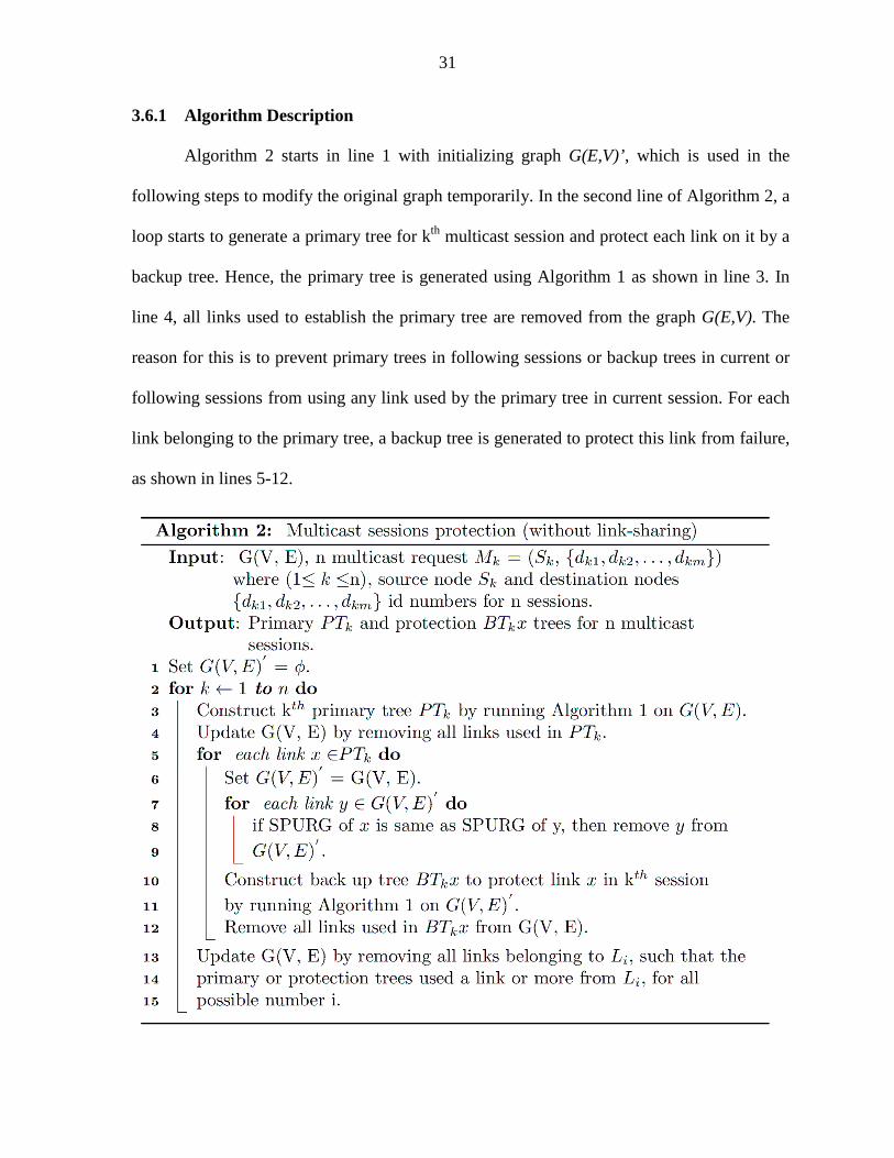
3.6.1 Algorithm Description
Algorithm 2 starts in line 1 with initializing graph G(E,V)’, which is used in the
following steps to modify the original graph temporarily. In the second line of Algorithm 2, a
loop starts to generate a primary tree for kth multicast session and protect each link on it by a
backup tree. Hence, the primary tree is generated using Algorithm 1 as shown in line 3. In
line 4, all links used to establish the primary tree are removed from the graph G(E,V). The
reason for this is to prevent primary trees in following sessions or backup trees in current or
following sessions from using any link used by the primary tree in current session. For each
link belonging to the primary tree, a backup tree is generated to protect this link from failure,
as shown in lines 5-12.

32
A copy of G(E,V) is used in line 6 to temporarily modify the graph to generate a
backup tree. Some links in the graph G(E,V)’ are removed because they cannot be used for
generating a backup tree. If a link with a SPURG that is the same as SPURG of the link to be
protected is used in the backup tree, then both links will fail together once the primary user
associated with this SPURG becomes active. Therefore, all links in G(E,V)’ that have a
SPURG that is the same as SPURG of the link to be protected will be removed as in lines 7-
9. After that, A backup tree for the link to be protected will be generated in lines 10-11 by
running Algorithm 1 on the modified graph G(E,V)’. All links used in the backup tree will be
removed from G(E,V) in line 12 so that next backup trees don’t use a link or more from the
links that already used for the recently established backup tree. The loop in line 2 continues
until all links in the primary tree for session k are protected by backup trees.
After establishing primary and backup trees for session k, the original graph needs to
be updated as in lines 13-15. This update includes removing all links belonging to Li, for all
possible number i, such that the primary tree or any backup tree uses a link or more from Li
will be removed from the original graph. The reason for that is to prevent next sessions from
using theses links which actually cannot be used by more than one session. Once a link or
more belonging to Li is used in a session, the wireless medium between the nodes in gi will be
entirely reserved for multicast session k’s transmission. Hence, no other session can use the
remaining links for its transmission, and it should be removed from the graph.
Algorithm 2 generates multicast trees and their protection trees using Algorithm 1,
and this implies finding the shortest path trees. A shortest path is not calculated only by
finding a path from source to destinations with minimum cost without taking into the
consideration the nature of cognitive radio networks. For example, some links must be

33
eliminated from being used in backup trees if they belong to the same SPURG of the link that
needs to be protected. A path with a higher cost may result, but it is important to do so to
protect the multicast session. Algorithm 2 uses Algorithm 1 to construct the multicast trees.
Therefore, the complexity of Algorithm 2 is O(nmE2 log V + nE3).
3.7 Protecting Multiple Multicast Sessions with Link-Sharing
In Algorithm 2, multiple multicast sessions are generated, and each link of the
primary tree is protected by a backup tree. Primary user interruption causes a failure to each
link affected by this interruption. However, the rest of links in the primary tree not affected
by primary user interruption are available. Hence, it is a waste of bandwidth to avoid using
links which have not failed in establishing the backup trees. Moreover, all links used in the
backup trees are dedicated for protecting one multicast session, and that may result in
reserving a huge portion of the bandwidth without using it efficiently. Furthermore, the cost
of supporting the multicast sessions and protecting them will increase if there is no link
sharing inside one session and also between different sessions. Therefore, we propose
multicast sessions protection with link-sharing algorithm which mitigates above drawbacks
of multicast sessions protection without link-sharing.
Multicast sessions protection with link-sharing algorithm allows link sharing inside
one session, and also between different sessions. Once a link in a primary tree fails, then each
backup tree can share all non-failed links in the primary tree in the same session and use
them in constructing the backup tree. Moreover, it is possible that non-failed links in any
backup tree in any session is used also in constructing a backup tree for another link. Since
our proposed algorithm is reactive, all backup trees need to be established in advance before

34
the failure happens. To protect a given link x, then any link in primary or backup trees in the
same session or in backup trees in other sessions cannot be used in protecting link x if its
SPURG is the same as SPURG of link x. The reason for eliminating the use of link with
SPURG which is the same as SPURG of the link to be protected is that all of them belong to
the same SPURG, and hence, they will fail together once the corresponding primary user
becomes active.
Example 2:
Using the same graph G(E,V) in Figure 3.6 and the same multicast request in
Example 1, primary tree can be constructed exactly the same way of constructing it in Figure
3.7. However, backup tree of link S-n3 can share some links used in the primary tree in the
same session as shown in Figure 3.9. The dashed links represent shared links between
primary and backup tree in case of link S-n3 failure, where the blue links represent the new
links used in the backup tree in addition to the shared links.
Figure 3.9: Backup tree for link S-n3 using shared links with primary tree.

35
Example 3:
We will show in this example multicast sessions sharing some links in their backup
trees. Suppose that two multicast requests are generated over the directed graph in Figure
3.10. The first multicast session is represented by source nodes S1and destination nodes d1
and d2, whereas the other multicast session is represented by source node S1 and destination
nodes d2 and d3. The red trees in Figure 3.10 represent primary trees for the two sessions. To
protect link n2-d2 in session 1 and link n4-d2 in session 2, 2 backup trees are required in
order to reroute the traffic in case of failures. By using our proposed algorithm, it is possible
that the two backup trees that belong to two multicast sessions can share some links as shown
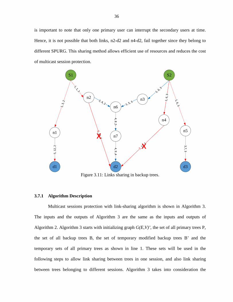
in Figure 3.11.
Figure 3.10: Two primary trees for two multicast sessions.
In each backup tree in Figure 3.11, some links of primary tree inside the same session
are shared (dashed red lines). Moreover, link n6-n7 and link n7-d2 are shared between the
two backup trees for link n2-d2 in session 1 and link n4-d2 in session 2 (dashed blue lines). It
36
is important to note that only one primary user can interrupt the secondary users at time.
Hence, it is not possible that both links, n2-d2 and n4-d2, fail together since they belong to
different SPURG. This sharing method allows efficient use of resources and reduces the cost
of multicast session protection.
n2
n6
n3
n7
d2
S2
n5
d3
n4
S1
n1
d1
3,7
, 3
4, 8
,54
, 9 ,45
, 1
2,
2 xx
Figure 3.11: Links sharing in backup trees.
3.7.1 Algorithm Description
Multicast sessions protection with link-sharing algorithm is shown in Algorithm 3.
The inputs and the outputs of Algorithm 3 are the same as the inputs and outputs of
Algorithm 2. Algorithm 3 starts with initializing graph G(E,V)’, the set of all primary trees P,
the set of all backup trees B, the set of temporary modified backup trees B’ and the
temporary sets of all primary trees as shown in line 1. These sets will be used in the
following steps to allow link sharing between trees in one session, and also link sharing
between trees belonging to different sessions. Algorithm 3 takes into consideration the

37
constraints imposed by dynamic nature of channel availability as a result of primary users
interruptions.

38
As shown in line 2, a loop starts to generate n multicast sessions and protect them
against one primary user interruption at a time. Line 3 is used to construct a primary tree for
kth session by running Algorithm 1 over the network graph. In line 4, the graph has to be
updated by removing all links used in constructing the primary tree in order to avoid having
other sessions use these links. In line 5, the set P, which is a union of all primary trees in all
sessions, is updated by including the recently established primary tree in it. The lines from 6
to 25 show the required steps used to construct a backup tree for the link that needs to be
protected. In backup tree construction, Algorithm 3 takes into consideration all links in
current and previous sessions that can be shared, in addition to remaining links in the original
graph.
In line 7, the original graph, primary tree in current session and the set of all backup
trees are copied, and the copies will be used in the following steps to avoid sharing the links
that should not be shared. The link that needs to be protected is removed from PTk’ to avoid
using it in the backup tree for that link, as shown in line 8. The backup tree that protects a
link should not share any link in the primary tree in the same session if both links have the
same SPURG value. Hence, the steps shown in the lines 9-11 are used to remove the links
that cannot be shared form the copy of the primary tree. The same procedure is applied for
the links belonging to the copy of backup trees set B’ or G(E,V)’ as shown in the lines 12-17.
All links in B’ or G(E,V)’ with a SPURG that is the same as the SPURG of the link to be
protected will be removed form B’ and G(E,V)’.
As mention previously, Algorithm 3 protects multicast sessions against one primary
user interruption at a time, and that may cause failures to multiple links belonging to different
sessions. Suppose that there is a link j in the current session, and we need to generate a

39
backup tree for this link. If there is a link t belonging to a primary tree in another session, and
j and t have the same SPURG value, then the backup tree for link j cannot use any link in B’
used to protect link t. The reason for this is to prevent failed links, belonging to different
multicast sessions and with the same SPURG, from generating backup trees that overlap and
use the same resource once a failure happen. If the backup trees for link t and j share at least
on common link, then both primary trees that link t and j belong to will not be protected once
the primary user corresponding to their SPURG becomes active. The procedures that prevent
this problem are shown in lines 18-20 in Algorithm 3.
All remaining links in sets PTk’ and B’ can be shared and used to generate a backup
tree BTk x to protect link x. These remaining links are already reserved either for primary tree
in current session or for backup trees in current or previously established sessions. Therefore,
the remaining links in PTk’ and B’ are all set to zero as shown in line 21. lines 22-23 shows
that the remaining links in G(E,V)’, PTk’ and B’ can be used to construct BTk x by running
Algorithm 1 on all links in the union (G(E,V)’ ⋃ PTk’ ⋃ B’). After generating the backup tree
BTk x to protect link x, all links used in BTk x are removed from G(E,V) as shown in line 24.
The reasons for that are to prevent primary trees in other sessions from using these reserved
links, and also to prevent backup trees in current and following sessions from using these
links directly without checking the possibility of sharing. In line 25, set B is updated by
including all links used in backup tree BTk x but not used in primary tree PTk’. Hence, backup
trees in next sessions will not share a link used in both primary and backup tree in a previous
session. The reason for that is to prevent any backup tree from using a link belonging to a
primary tree in another session. The lines 26-28 do exactly the same job of lines 13-15 in
Algorithm 2 which is used to update the original graph G(E,V). Algorithm 3 uses Algorithm
40
1 to construct the multicast trees, hence, the complexity of Algorithm 3 is O(n2 E2 + nmE2
log V + nE3).
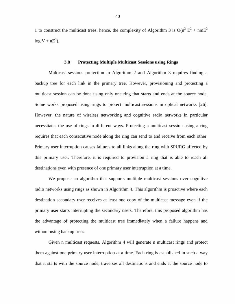
3.8 Protecting Multiple Multicast Sessions using Rings
Multicast sessions protection in Algorithm 2 and Algorithm 3 requires finding a
backup tree for each link in the primary tree. However, provisioning and protecting a
multicast session can be done using only one ring that starts and ends at the source node.
Some works proposed using rings to protect multicast sessions in optical networks [26].
However, the nature of wireless networking and cognitive radio networks in particular
necessitates the use of rings in different ways. Protecting a multicast session using a ring
requires that each consecutive node along the ring can send to and receive from each other.
Primary user interruption causes failures to all links along the ring with SPURG affected by
this primary user. Therefore, it is required to provision a ring that is able to reach all
destinations even with presence of one primary user interruption at a time.
We propose an algorithm that supports multiple multicast sessions over cognitive
radio networks using rings as shown in Algorithm 4. This algorithm is proactive where each
destination secondary user receives at least one copy of the multicast message even if the
primary user starts interrupting the secondary users. Therefore, this proposed algorithm has
the advantage of protecting the multicast tree immediately when a failure happens and
without using backup trees.
Given n multicast requests, Algorithm 4 will generate n multicast rings and protect
them against one primary user interruption at a time. Each ring is established in such a way
that it starts with the source node, traverses all destinations and ends at the source node to

41
create a ring as shown in Figure 3.12. Under normal network operation, source node S
forwards it message to both nodes connected to it, which is n1 and n3. Then, each node that
receives a message forwards it to the next node connected to it along the ring until one node
receives two copies of the message. If a node receives two copies of a message from two
neighboring nodes along the ring, then it will stop forwarding the message since it can
conclude that all other destinations have received the message.
Figure 3.12: A multicast session protected by a ring.
Suppose that a primary user PU1 starts transmitting, then all links with a SPURG
corresponding to PU1 will fail as shown in Figure 3.13. Although both links between S and
d1 fail when PU1 becomes active, node d1 is still reachable by the source node using the path
S-n3-d2-n2-d1. As a result of that, cognitive radio networks in this case can recover from the
failure without rerouting the traffic to another backup tree.

42
3.8.1 Algorithm Description
The first line of Algorithm 4 initializes graph G(E,V)’ and Pathk’ , which will be used
to temporarily modify the original graph and Pathk in the following steps. In line 2, a loop
starts constructing multicast sessions using ring structure. In lines 3-5, the original directed
graph is copied to graph G(E,V)’, source node is set to the Sk and destination nodes list D is
created. Then, shortest path from source node to closest destination in list D is created using
Algorithm 1, as shown in lines 6-8. The input to Algorithm 1 is the multicast request M =
(Sk,, {dkx}), where dkx is the closest destination to Sk. It is important to note that each two
nodes along the ring must be able to send to and receive from each other, and that may
happen over one or two channels. Therefore, two links in opposite direction must be
available in the directed graph between any consecutive nodes along the ring. This restriction
makes each node along the ring able to receive at least one copy of the message even with
presence of a link failure.
We assume that a maximum of one primary user will be active at a time. To make the
ring achieve our goal of delivering the message to all destinations even in the presence of a
primary user transmission, each path from a source node to a destination or from a
destination to a destination must consist of links with unique SPURG values. For example,
the path from S to d1 in Figure 3.13 consists of links with SPURG values equal to 1 and 5.
Hence, all other paths, either from d1 to d2 or from d2 to S, must consist of links with SPURG
values other than 1 and 5. After establishing a path to the closest destination, all links in the
graph with SPURG values equal to any SPURG values of the links along the path will be
removed from the graph as shown in lines 9-11. The purpose of removing these links is to

43
prevent next paths along the ring from using any link with SPURG value already used in a
link or more in previous paths.

44
Figure 3.13: Multicast session protection in case of primary user appearance.
After establishing the path from source node to the first destination, this destination
will be set as a source node, as shown in line 12. In line 13 and 14, all steps from line 6 to
line12 will be repeated until all destinations are reached. Once all destinations are reached, a
path starting from Sk and traversing all destination nodes is created, which is called Pathk.
In lines 15-16, another path is established from Sk to the last reached destination in
order to create a ring. If the ring is always created by connecting the last reached destination
node in Pathk to the source node, then this may lead to block the session if it is not possible
to find a path connecting these two nodes. Even if there are enough resources to establish a
path from last destination in Pathk to source node, it is possible to find another ring that has a
lower cost, and does not directly connect the last destination to the source node. Hence, the
procedures in line 17-26 are used to find a ring that minimizes the cost while considering
closing the ring from a node in Pathk other than the last reached destination.
In Figure 3.14, an example shows two different ways to create a ring for protecting
the multicast session. In (a), Pathk is established, which starts from the source node S and

45
traverses all destination nodes, d1, d2 and d3. The total cost of Pathk is equal to:
1+1+1+1+2+2 = 8. By connecting the last reached destination, d3, to the source node, a ring
is created, as shown in (b), with cost equal to: 8+3+3 = 14. However, another ring with lower
cost is shown in (c), where d3 is not directly connected to the source node through a direct
path. The new ring is created by connecting d3 to d1, d2 to the source node and removing all
links between d1 and d2. Therefore, the cost of the new ring is equal to: 1+1+5+2+3 = 12.
Hence, the ring in (c) has a lower cost, and it should be selected for protecting the multicast
session instead of using the ring shown in (b).
Lines 17-26 describes the procedures used to modify and connect Pathk to the source
node in order to create a ring that minimizes the cost. These lines test combinations of
finding a ring by connecting last destination in Pathk to a node on Pathk, connecting a node
on Pathk to the source node, and removing the path between these two nodes. It is important
to note that last destination is always directly connected to the source node by a direct path
when the number of destinations is 2. However, we can apply the procedures in line 17-25 if
the number of destinations is 3 or more.
In line 27, the ring with the lowest cost is selected to generate and protect the
multicast session. If the number of destinations is 2, then there is only one ring that connects
the last destination in Pathk to the source node. Otherwise, one ring with the lowest cost is
selected out of m-1 possible rings. Finally, the original graph is updated in lines 28-30 as
described in lines 13-15 of Algorithm 2, and also by removing all used links in the selected
ring. Then, the loop in line 2 will start again to create another ring for another multicast
session until all multicast sessions are created.

46
Algorithm 4 uses Algorithm 1 to construct all paths between source and destination
nodes, and between any two destination nodes along the ring. Since Algorithm 1 is used with
m=1 in this case, the complexity of Algorithm 1 is O(E log V + E2). Accordingly, total time
complexity for Algorithm 4 is O(nmE log V + nmE2).
Figure 3.14: Creating a ring for multicast protection. In (a): a path starts from source
node and traverses all destination nodes, (b): creating a ring by connecting last destination to the source node, and (c): creating a ring, which has a lower cost, without connecting the last destination to the source node.

47
3.9 Chapter Summary
In this chapter, we proposed three algorithms that provision robust multicast sessions
in cognitive radio networks. These algorithms are: 1) Protecting multiple multicast sessions
without link-sharing, 2) Protecting multiple multicast sessions with link-sharing and 3)
Protecting multiple multicast sessions using rings. These proposed algorithms protect
multiple multicast sessions against one primary user interruption at a time. In the first and
second algorithms, tree-based link protection is used, whereas the third algorithm uses rings
for protection. Our proposed algorithms provision protection for multicast sessions while
minimizing the cost of multicast sessions and maximizing the number of sessions that can be
accommodated in the network.

48
CHAPTER 4. SIMULATION RESULTS
In this chapter, we evaluate the performance of the three proposed algorithms that
provision robust multicasting in cognitive radio networks. In first section of this chapter, we
compare the performance our proposed algorithms, multicast sessions protection with link-
sharing, with optimal solution for single multicast session. In the second section, we compare
all our three proposed algorithms to show their performance and the trade-off between them.
4.1 Single Multicast Session
In this section, we compare the number of paths that can be established to reach
destination nodes using optimal solution in [19] with our proposed algorithm, multicast
sessions protection with link-sharing. These paths include the paths in the primary tree and
the average number of paths in the backup trees for single multicast session. Also, we
compare the number of links in the primary and backup tree used to establish the multicast
session. The optimal solution in [19] is represented by the number of paths and links used to
support single multicast session.
In performance evaluation, we consider each generated network with the following
parameters: 25 secondary users, 10 secondary users groups per each channel, one secondary
users groups, gi, per each SPURG, one source node and 8 destination nodes. Secondary users
with a common channel are assigned randomly to a secondary users group, gi. Each link in
the network is assigned a random cost which ranges from 1 to 5, where all links belonging to
the same set Li are assigned same cost. Random sessions with 8 destinations are generated

49
over 100 random graphs, and then the average number of paths and links are calculated with
respect to the number of available channels.
Figure 4.1 shows a comparison between the numbers of generated paths with respect
to the number of available channels using the optimal solution in [19] and our proposed
algorithm, multicast session protection with link-sharing. The number of established paths is
strongly related to the number of available channels, where it increases as the number of
available channels increases. In other words, having more channels increases the possibility
of reaching more destinations. It is shown that the number of generated paths using our
proposed algorithm is close to the optimal solution when the number of available channel is
small. As the number of available channels increased to 7, the difference between the optimal
solution and our proposed algorithm is approximately 2 paths.
Figure 4.1: Average number of paths with respect to the number of channels.
The number of links used in single multicast session increases as the number of
available channels increases as shown in Figure 4.2. The reason is that the number of paths
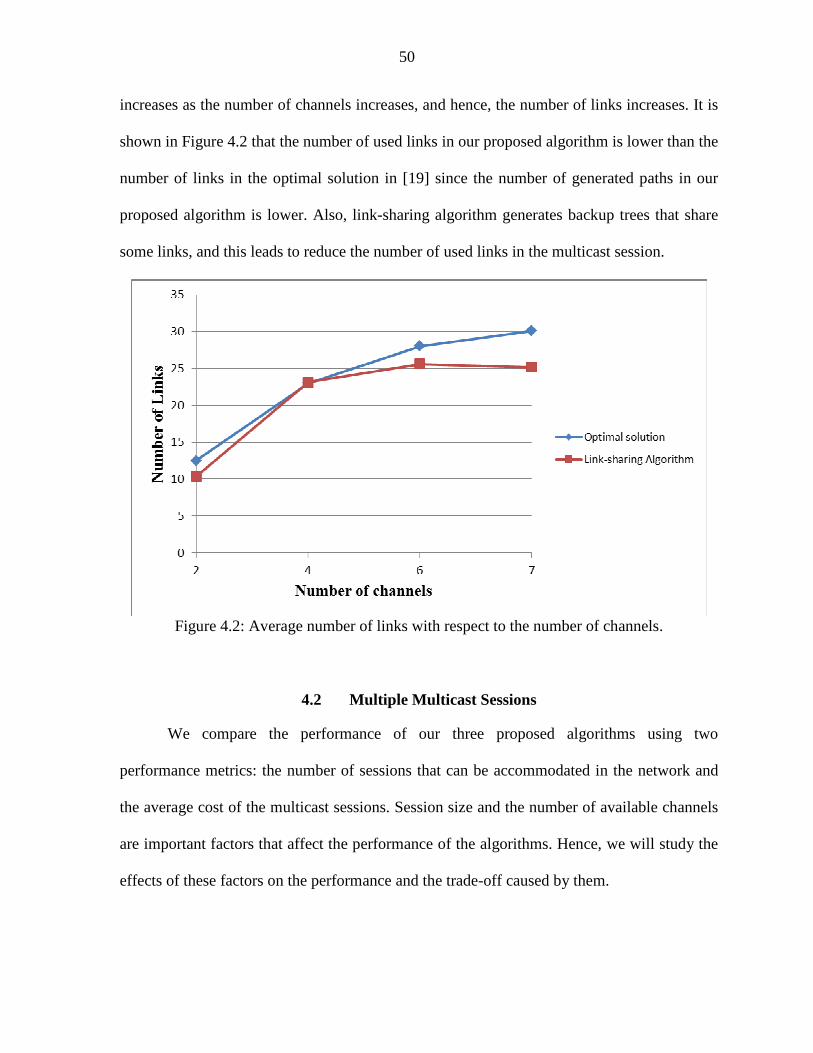
50
increases as the number of channels increases, and hence, the number of links increases. It is
shown in Figure 4.2 that the number of used links in our proposed algorithm is lower than the
number of links in the optimal solution in [19] since the number of generated paths in our
proposed algorithm is lower. Also, link-sharing algorithm generates backup trees that share
some links, and this leads to reduce the number of used links in the multicast session.
Figure 4.2: Average number of links with respect to the number of channels.
4.2 Multiple Multicast Sessions
We compare the performance of our three proposed algorithms using two
performance metrics: the number of sessions that can be accommodated in the network and
the average cost of the multicast sessions. Session size and the number of available channels
are important factors that affect the performance of the algorithms. Hence, we will study the
effects of these factors on the performance and the trade-off caused by them.

51
The network parameters used in the simulation are described as follows. The network
consists of 50 secondary users, where secondary users with a common channel are grouped
into up to 36 secondary users group, gi. Each secondary users group, gi, consists of up to 5
secondary users, and each SPURG consists of up to three secondary users groups. The cost of
each link in the network is assigned a value ranging from 1 to 5, where all links belong to the
same set, Li, are assigned the same cost. In the simulation, 100 random network graphs, and
then 100 multicast sessions are generated over each network graph. After that, we calculate
the average number of sessions that can be accommodated in the network and the average
cost of multicast sessions.
In the following, we will show the effect of the session size and the number of
available channels on the performance of the three proposed algorithms. We assume that the
session is blocked if one or more destination nodes are not reachable.
4.2.1 Performance Comparison with Respect to Sessions Sizes We compare the number of multicast sessions that can be accommodated in the
network for the three proposed algorithms as shown in Figure 4.3. Since larger sessions tend
generally to consume a greater number of network links, the number of sessions that can be
accommodated in the network decreases as session sizes increases. Therefore, we see in
Figure 4.3 that the number of sessions decreases as the number of destination increases for all
three algorithms.
It is shown in Figure 4.3 that multicast sessions protection using link-sharing
algorithm achieves the highest number of sessions. Link-sharing method allows sharing some
links inside one session and also between different sessions, and hence, network links are

52
used in a more efficient way. Therefore, a higher number of sessions can be accommodated
in the network using multicast sessions protection with link-sharing algorithm compared with
the other two algorithms. When the number of destination is small, multicast sessions
protection without link-sharing algorithm outperforms multicast sessions protection using
ring algorithm. On the other hand, multicast sessions protection using ring algorithm
outperforms multicast sessions protection without link-sharing algorithm when the number of
destinations becomes larger.
Figure 4.3: Number of multicast sessions in the network with respect to session size.
Figure 4.4 shows the average cost per session with respect to session size. As the
number of destinations increases, the cost per session increases since a higher number of
links is required. Multicast sessions protection using rings achieves the lowest cost, and the
reason is that it does not require protecting every link by a protection tree compared with the
other two algorithms. Multicast sessions protection without link-sharing algorithm achieves
the highest cost per session because it does not support link-sharing and requires a protection

53
tree for each link. On the other hand, link-sharing method used in multicast sessions
protection with link-sharing algorithm allows it to outperform multicast sessions protection
without link-sharing algorithm.
0
5
10
15
20
25
30
35
40
45
50
2 3 4 5 6 7 8
Cos
t
Number of destinations
Protection with link sharing
Protection without link sharing
Protection with rings
Figure 4.4: The cost of the multicast session with respect to its size.
4.2.2 Performance Comparison with Respect to Number of Channels
The number of available channels is an important factor that affects the performance
of the network. It is shown in Figure 4.5 that increasing the number of available channels for
secondary users increases the number of sessions that can be accommodated in the network.
Having a diverse set of available channels provides a diverse set of backup channels that can
be used when a primary user becomes active. Hence, the probability of finding a ring or
backup trees that protect the multicast session increases as the number of available channels
increases. Therefore, a higher number of protected sessions can be accommodated in the
network when the number of available channels increases.

54
Multicast sessions protection with link-sharing algorithm always achieves the highest
number of sessions that can be accommodated in the network. Link-sharing method allows
sharing some channel links, and hence, using the links in the network in more efficient way.
Therefore, increasing the number of channel links increases the chance of sharing these links,
and increasing the number of sessions in the network. The gap between protection with link-
sharing and protection without link-sharing increases as the number of available channels
increases. Multicast protection using rings algorithm outperforms multicast protection
without link-sharing algorithm as the number of channels is increased to 6 or greater.
Figure 4.5: Number of multicast sessions in the network with respect to the number of
available channels.
It is shown in Figure 4.6 that the multicast session cost decreases as the number of
available channels increases. Having a larger number of available channels increases the
probability of finding a path with a lower cost, where different channels may have different
costs. Multicast session protection using rings algorithm generates protected multicast
sessions with the lowest cost compared to the other two algorithms. Sharing some links

55
within one session or between different sessions allows multicast session protection with
link-sharing algorithm to outperform multicast session protection without link-sharing
algorithm.
Figure 4.6: The cost of the multicast session with respect to the number of available
channels.
4.3 Chapter Summary
In this chapter, we compared the performance of multicast session protection with
link-sharing algorithm to the optimal solution in [19], for a single multicast session. Also, we
compared the performance of our three proposed algorithms in terms of cost and the number
of sessions accommodated in the network. It is shown that the session size and the number of
available channels affect the performance of our proposed algorithm significantly. The
simulation results show that multicast session protection with link-sharing algorithm
outperforms the other two algorithms in terms of the number of accommodated sessions in

56
the network. However, multicast session protection using rings algorithm generates multicast
sessions with the lowest cost compared to the other proposed algorithms.

57
CHAPTER 5. CONCLUSIONS AND FUTURE WORK
5.1 Summary and Conclusions
In this thesis, we propose three algorithms that provision and protect multiple
multicast sessions in cognitive radio networks. These algorithms are: multicast sessions
protection without link-sharing, multicast sessions protection with link-sharing and multicast
sessions protection using rings. The goals of our three proposed algorithms are: provisioning
multiple multicast sessions in cognitive radio networks, protecting all multicast sessions
against one active primary user at a time, increasing the number of sessions that can be
accommodated in the network and minimizing the cost of the multicast sessions.
In multicast sessions protection without link-sharing algorithm, multiple multicast
sessions are provisioned by constructing a primary multicast tree for each requested multicast
session. The multicast session is protected by protecting each link of the primary multicast
tree by a backup tree. However, multicast sessions protection with link-sharing algorithm
also protects each link in the primary tree by a backup tree, but it allows sharing some links
in the construction of the backup trees. Therefore, the backup trees are allowed to share some
links in primary tree of the same session, and share some links in backup trees of any session.
The third proposed algorithm provisions and protects multiple multicast sessions using rings.
Each ring starts and ends at the source node, and traverses all destination nodes. It is shown
that each destination receives at least one copy of the multicast message once a primary user
becomes active.
Our simulation results compare the performance of our three proposed algorithms.
We show that the number of accommodated sessions in the network increases and the cost of

58
multicast sessions decreases when the number of available channels increases or the session
size becomes smaller. Multicast sessions protection with link-sharing can support the highest
number of multicast sessions in the network compared with the other two algorithms.
However, multicast sessions protection using ring can generate multicast sessions with the
lowest cost compared with the other proposed algorithms.
5.2 Future Work
We plan to continue this research by extending it in a number of directions:
1- There are several modes of group communication, and the thesis has only
considered one type of group communication, which is one-to-many. We plan to
extend our algorithm to consider many-to-one and many-to-many communication.
2- Different multicast requests may have different QoS requirements. Therefore, we
will consider the maximum delay and minimum bandwidth for each multicast
request while provisioning robust multicast sessions in cognitive radio networks.
3- We will extend our algorithms to consider the dynamics of primary users which
may cause failures to primary or backup trees. If a primary user interruption
causes a failure to a primary tree, then the backup tree is selected as a primary
tree, and a new back up tree should be generated. On the other hand, a new
backup tree is generated without changing the primary tree if the primary user
causes a failure to a backup tree.
4- Multicast requests last for different amount of time depending on the
requirements of the users who initiate the requests. We plan to develop our

59
proposed algorithms to consider the dynamics of multicast sessions and which
resource should be released for the next multicast sessions.

60
BIBLIOGRAPHY
[1] I. F. Akyildiz, W.-Y. Lee, M. C. Vuran, and S. Mohanty, “Next generation/ dynamic spectrum access/cognitive radio wireless networks: A survey,” Comput. Netw., vol. 50, no.13, pp. 2127–2159, May 2006. [2] Federal Communications Commission (FCC). Notice of proposed rulemaking and order. Report ET Docket No 03-322, Dec. 2003. [3] F. K. Jondral, “Software-defined radio – basics and evolution to cognitive radio,” EURASIP Journal on Wireless Communication and Networking, vol. 2005, no. 3, pp. 275–283, Apr. 2005. [4] C. Cordeiro, K. Challapali, D. Birru, and S. Shankar N, “IEEE 802.22: The first worldwide wireless standard based on cognitive radio,” in Proc. IEEE DySPAN, 2005, pp. 328–337. [5] “IEEE P802.11af™/D3.0 Draft Standard for Information Technology - Telecommunications and Information Exchange Between Systems - Local and Metropolitan Area Networks - Specific Requirements - Part 11: Wireless LAN Medium Access Control (MAC) and Physical Layer (PHY) Specifications Amendment 5: TV White Spaces Operation.”, Jan. 2013. [6] A. Flores, R. Guerra, E. Knightly, P. Ecclesine, and S. Pandey, “IEEE 802.11af: A Standard for TV White Space Spectrum Sharing," IEEE Communications Magazine, vol. 51, no. 10, pp. 92–100, Oct. 2013. [7] M. Sherman, A. Mody, R. Martinez, C. Rodriguez, and R. Reddy, “IEEE standards supporting cognitive radio and networks, dynamic spectrum access, and coexistence,” IEEE Communications Magazine, vol. 46, no. 7, pp. 72– 79, Jul. 2008. [8] I. F. Akyildiz, X. Wang, and Wang, W., "Wireless Mesh Networks: A Survey," Computer Networks Journal (Elsevier), vol. 47, no. 4, pp. 445-487, Mar. 2005. [9] K. R. Chowdhury and I. F. Akyildiz, "Cognitive Wireless Mesh Networks with Dynamic Spectrum Access," IEEE Journal on Selected Areas in Communications, vol. 26, no. 1, pp. 168-181, Jan. 2008. [10] I.F. Akyildiz, W. Y Lee and K. Chowdhury, "CRAHNs: Cognitive Radio Ad Hoc Networks," Ad Hoc Networks (Elsevier) Journal, vol. 7, no. 5, pp. 810-836, Jul. 2009. [11] T. Chen, H. Zhang, M. Matinmikko, M. Katz, "CogMesh: Cognitive Wireless Mesh Networks," In IEEE GLOBECOM Workshops, 2008, pp. 1-6.

61
[12] H. Arslan and T. Yucek, "Spectrum Sensing for Cognitive Radio Applications", Book Chapter, Cognitive Radio, Software Defined Radio, and Adaptive Wireless Systems, Springer, ISBN: 978- 1402055416, Ed: Huseyin Arslan, 2007. [13] I. F. Akyildiz , W. Y. Lee, M. C. Vuran and S. Mohanty, "A Survey on Spectrum Management in Cognitive Radio Networks," IEEE Communications Magazine, vol. 46, no. 4, pp. 40-48, Apr. 2008. [14] W. Y. Lee and I. F. Akyildiz "A Spectrum Decision Framework for Cognitive Radio Networks," IEEE Transactions on Mobile Computing, vol. 10, no. 2, pp. 161-174, Feb. 2011. [15] I. Christian, S. Moh, I. Chung, and J. Lee, “Spectrum Mobility in Cognitive Radio Networks,” IEEE Communications Magazine, vol. 50, no. 6, pp. 114–121, Jun. 2012. [16] U. Varshney, “Multicast Over Wireless Networks,” Communications of the ACM, vol.45, no. 12, pp. 31-38, Dec. 2002. [17] Y. Shi Gao, Y. T. Hou, H. D. Sherali, and H. Zhou, ”Multicast Communications in Multi-Hop Cognitive Radio Networks,” IEEE Journal on Selected Areas in Communications, vol.29, no.4, pp.784-793, Apr. 2011. [18] D. Hu, S. Mao, Y. Hou and J. Reed, "Scalable video multicast in cognitive radio networks", IEEE Journal on Selected Areas in Communications , vol. 28, no. 3, pp.334-344, 2010.
[19] S. Alnabelsi, A. E. Kamal, "Resilient Multicast Routing in CRNs Using a Multilayer Hypergraph Approach ", IEEE International Conference on Communications (ICC), 2013, pp. 2910-2915.
[20] J. Jin, H. Xu, and B. Li, “Multicast Scheduling with Cooperation and Network Coding in Cognitive Radio Networks,” IEEE INFOCOM, 2010, pp. 1-9.
[21] H. M. Almasaeid and A. E. Kamal, “Exploiting multichan nel diversity for cooperative multicast in cognitive radio mesh networks,” IEEE/ACM Transactions on Networking, 2013.
[22] Z. Shu, Y. Qian, Y. Yang and H. Sharif. “Channel Allocation and Multicast Routing in Cognitive Radio Networks,” Wireless Communications and Networking Conference (WCNC), 2013, pp. 1703-1708. [23] H. M. Almasaeid, T. H. Jawadwala, and A. E. Kamal, “On demand multicast routing in cognitive radio mesh networks,” In IEEE Global Communications Conference (GLOBECOM), Dec. 2010, pp. 1-5. [24] R. Mao and H. Li, ”Protecting Cognitive Radio Networks Against Primary Users: A Backup Path Approach,” In the proceedings IEEE Globecom, 2011, pp. 1-6.

62
[25] A. Haider and R. Harris, “Recovery Techniques in Next Generation Networks,” IEEE Communications Surveys & Tutorials, vol. 9, no. 3, pp. 2-17, 2007. [26] N. Singhal and B. Mukherjee, “Protecting multicast sessions in WDM optical mesh networks,” Journal of Lightwave Technology, vol. 21, no. 4, pp. 884–892, 2003