an architecture for scalable qos multicast provisioning ucla csd
TRANSCRIPT

An Architecture for Scalable QoS Multicast Provisioning
UCLA CSD TR # 010030
Jun-Hong Cui, Aiguo Fei, Mario Gerla, Michalis Faloutsos
Computer Science Department Computer Science & Engineering
University of California University of California
Los Angeles, CA 90095 Riverside, CA 92521
Abstract
IP multicast suffers from scalability problems as the number of concurrently active multicast groups increases, since it requires
a router to keep forwarding state for every multicast tree passing through it. In QoS multicast provisioning, the problem becomes
even worse, since not only the forwarding state but also the resource requirement of a multicast group needs to be kept at the
router. Previously, we proposed and evaluated a novel scheme called aggregated multicast to reduce multicast state. In this report,
we present an architecture, called aggregated QoS multicast(AQM), for scalable QoS multicast provisioning. In this architecture,
we examine how we can use aggregated multicast to support QoS multicast efficiently in Diff-Serv-Supported MPLS networks.
QoS Multicasting is a multifacet problem, involving routing, admission control, resource management and other related issues.
In AQM, we provide efficient and practical solutions for those issues. AQM is scalable, especially for QoS multicast provisioning
in transit domains. Our design shows that AQM is feasible and implementable based on MPLS and Diff-Serv techniques. With
the increasing demand of interactive, real-time applications, such as videoconferencing, sportcasting, workgroups, internet games
etc., AQM appears to be a very simple, attractive solution for scalable, real-time QoS multicast services in the Internet.
I. I NTRODUCTION
Multicast is a mechanism to efficiently support multi-point communications. IP multicast utilizes a tree delivery
structure on which data packets are duplicated only at fork nodes and are forwarded only once over each link. Thus IP
multicast is resource-efficient in delivering data to a group of members simultaneously and can scale well to support
very large multicast groups. However, even after approximately twenty years of multicast research and engineering
effort, IP multicast is still far from being as common-place as the Internet itself.
Multicast state scalability is among the technical difficulties that delay its deployment. In unicast, address aggre-
gation coupled with hierarchical address allocation has helped achieve scalability. This can not be easily done for
multicasting, since the current multicast address corresponds to a logical group and does not convey any information
on the location of its members. A multicast distribution tree requires all tree nodes to maintain per-group(or even
per-group/source) forwarding state, and the number of forwarding state entries grows with the number of “passing-by”
groups. As multicast gains widespread use and the number of concurrently active groups grows, more and more for-
warding state entries will be needed. More forwarding entries translate into more memory requirement, and may also
lead to slower forwarding process since every packet forwarding action involves an address look-up. This is perhaps
1

the main scalability problem with IP multicast when the number of simultaneous on-going multicast sessions is very
large.
Recognition of the forwarding-state scalability problem has prompted some recent research in forwarding state
reduction. Some architectures aim to completely eliminate multicast state at routers [13, 24] using network-transparent
multicast, which pushes the complexity to the end-points. Some other schemes attempt to reduce forwarding state by
tunneling[28] or by forwarding state aggregation[23, 27]. Apparently, less entries are needed at a router if multiple
forwarding state entries can be aggregated into one. Thaler and Handley analyze the aggregatability of forwarding state
in[27] using an input/output filter model of multicast forwarding. Radoslavov et al. propose algorithms to aggregate
forwarding state and study the bandwidth-memory tradeoff with simulation in [23]. Both these works attempt to
aggregate routing state after this has been allocated to groups. It is still an open question how much aggregation can
be achieved or whether this approach is applicable at all in real systems.
Previously we proposed and evaluated a novel scheme called aggregated multicast[12] to reduce multicast state.
One main difference compared with the other approaches is that, in aggregated multicast multiple groups are forced to
share one distribution tree, which we call anaggregated tree. This way the total number of trees in the network may
be significantly reduced and so is forwarding state: core routers need to keep state only per aggregated tree instead
of per group. While this approach significantly reduces the number of forwarding state entries and alleviates tree
management overhead, it may also waste bandwidth as it delivers data to non-group-members. The issue is thus the
trade-off between control O/H savings via aggregation and bandwidth wastage introduced by common tree sharing.
An important motivation for our aggregated multicast work is the provisioning of QoS multicast in future QoS-
enabled networks. Though most research papers on QoS multicast are focusing on solving a theoretical constrained
multicast routing problem, there have been several more pragmatic efforts to bring QoS into the existing IP multi-
cast architecture, such as RSVP [29], QoSMIC [4], QoS extension to CBT [15], and PIM-SM QoS extension [5].
But all these schemes are using per-flow state. Today people are backing away from micro-flow based QoS archi-
tecture, namely the Integrated Services architecture(IntServ)[8]. The reason behind it is simple: requiring per-flow
reservation and data packet handling, Integrated Services architecture has scalability problem at network core routers.
The recent trend towards QoS provisioning is aggregated flow based solutions, namely, the Differentiated Services
architecture(Diff-Serv)[6] and the Multiple Protocol Label Switching (MPLS) technology[25]. To incorporate the
per-flow state requirement and traffic management of multicast in a per class architecture might be inefficient for a
Diff-Serv or MPLS network. Besides scalability issue, another problem is that, traffic control elements may be unable
to predict traffic loads on every link because of multicast streams which consume network resources differently than
point-to-point flows. There is recent research [10, 14] targeted to MPLS support of Differentiated Services, but only
for unicast. There are also some proposals about supporting multicast in MPLS networks [20, 21], but their focus is to
2

construct a multicast traffic engineering tree by building multicast trees immediately on L2 or mapping L3 trees onto
L2. Using aggregated multicast, we can simplify traffic management and facilitate QoS provisioning for multicast:
(1) push per group multicast state to network edges and reduce multicast state in the network core; (2) pre-assign
resource/bandwidth (or reserve on demand) only for a small number of aggregated trees.
In our previous work[12, 11], we discussed the feasibility of aggregated multicast and evaluated the aggrega-
tion/bandwidth trade-off using simulation. In this report, we present an architecture, called aggregated QoS multi-
cast(AQM), for scalable QoS multicast provisioning. In AQM, we examine how we can use aggregated multicast to
support QoS multicast efficiently in Diff-Serv-Supported MPLS networks. QoS Multicasting is a multifacet problem,
involving routing, admission control, resource management and many other issues. Our goal is to provide efficient
and practical solutions for those issues. Our analysis shows that AQM is feasible and implementable based on MPLS
and Diff-Serv techniques. With the increasing demand of interactive, real-time applications, AQM will become a very
promising solution for scalable, real-time QoS multicast services in the Internet.
The rest of this report is organized as follows. Section II gives some background on IP multicast and reviews some
related work. Section III introduces the concept of aggregated multicast. Section IV presents the AQM architecture in
detail. Section V evaluates costs and benefits of AQM. Then Section VI discusses some related open issues. Finally
Section VII offers an overall summary of our contributions.
II. BACKGROUND AND RELATED WORK
A. Routing Architecture of Internet Multicast
IP multicast utilizes a tree structure to deliver multicast packets for a group. At the router level, a multicast tree
consists of designated routers which have group member(s) in their subnets and other intermediate routers which
help transport multicast traffic. Multicast routing protocols determine how a multicast tree is formed. To determine
how to forward multicast packets received, a router maintains forwarding-state information for groups in which it
is an in-tree router. Depending on the routing protocol, forwarding-state information may have entries per group
or per group/source. Multicast routing protocols determine how forwarding state is obtained and maintained. In
MOSPF[19], routers within a domain exchange group membership information with each other. Each router com-
putes a source-based multicast tree from which it obtains forwarding state that consists of (group/source, expected
in-interface, out-interface(s)) information. In CBT[3] or PIM-SM[9], a group member sends an explicit join request
towards a core router or a rendezvous point (RP). The request is forwarded and processed by intermediate routers and
the corresponding forwarding state is installed at each router.
The Internet consists of numerous Autonomous Systems (AS) or domains. Domains may be connected as service
provider/customers in a hierarchical manner or connected as peering neighbors, or both, as illustrated in Fig. 1. Nor-
3

mally a domain is controlled by a single entity and can run an intra-domain multicast routing protocol of its choice.
An inter-domain multicast routing protocol is deployed at border routers of a domain to construct multicast trees
connecting to other domains. A border router capable of multicast communicates with its peer(s) in other domain(s)
via inter-domain multicast protocols and routers in its own domain via intra-domain protocols, and forward multicast
packets across the domain boundary.
B. Other Related Work
Besides state aggregation approach[23, 27], some other work also attempts to reduce or eliminate multicast state.
Xcast[7] proposes to code a set of destinations’ addresses in a multicast packet so a router doesn’t need to maintain
state information for the group. It aims to be an alternative for IP multicast for very small groups or for Inter-domain
multicast. It doesn’t require a router to maintain multicast states but requires more processing of data packets at each
router.
Alternatively, in Yoid[13] and End-System Multicast[24], a self-organizing tree (and/or mesh) among group mem-
bers is constructed to provide multi-point communications among them without network-layer multicast support. In
this approach, native multicast may only be used within a limited scope[13] (e.g., at LAN level), while unicast is used
pervasively among members. Because only members are involved in replicating and forwarding multicast packets,
it is transparent to routers. Yoid and End-System Multicast might be a good alternatives for small-scale multicast
applications; however, it is difficult for them to scale up to support large-scale multicast applications like Internet TV
that can have millions of group members.
Both the tunneling approach proposed in [28] and the “REUNITE” approach in [26] attempt to eliminate multicast
forwarding state atnon-branchingrouters (i.e., routers that forward multicast packets received for a group to only one
out-going interface). Tian and Neufeld[28] propose to dynamically establish tunnels over non-branching links (thus
non-branching routers in between do not need state for that group). REUNITE[26] by Stoica et al. essentially proposes
an alternative to IP multicast, in which a multicast group is identified by a tuple of root node IP address and a port
number. Multicast state is installed at branching nodes only and packet forwarding is based on unicast in between.
Multicast state is recursively setup through explicit joining of members.
III. T HE CONCEPT OFAGGREGATEDMULTICAST
Aggregated multicast is targeted as an intra-domain multicast provisioning mechanism in the transport network.
For example, it can be used by an ISP (Internet Service Provider) to provide multi-point data delivery service for its
customers and peering neighbors in its wide-area or regional backbone network (which can be just a single domain).
The key idea of aggregated multicast is that, instead of constructing a tree for each individual multicast session in the
core network (backbone), one can have multiple multicast sessions share a single aggregated tree to reduce multicast
4
Domain B
Domain A
Customer networks, domain D
E1
X1
D1Y1
C1
B1
A4
A1 A3
A2
Ab
Aa
Domain E
Domain Y
Domain CDomain X
Tunnel
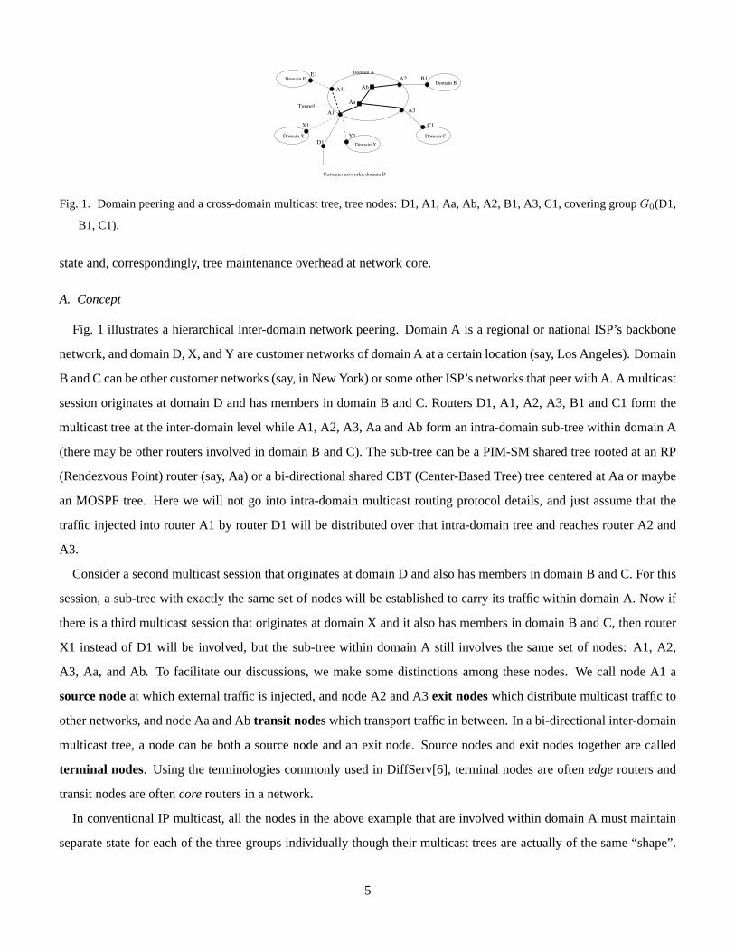
Fig. 1. Domain peering and a cross-domain multicast tree, tree nodes: D1, A1, Aa, Ab, A2, B1, A3, C1, covering groupG0(D1,
B1, C1).
state and, correspondingly, tree maintenance overhead at network core.
A. Concept
Fig. 1 illustrates a hierarchical inter-domain network peering. Domain A is a regional or national ISP’s backbone
network, and domain D, X, and Y are customer networks of domain A at a certain location (say, Los Angeles). Domain
B and C can be other customer networks (say, in New York) or some other ISP’s networks that peer with A. A multicast
session originates at domain D and has members in domain B and C. Routers D1, A1, A2, A3, B1 and C1 form the
multicast tree at the inter-domain level while A1, A2, A3, Aa and Ab form an intra-domain sub-tree within domain A
(there may be other routers involved in domain B and C). The sub-tree can be a PIM-SM shared tree rooted at an RP
(Rendezvous Point) router (say, Aa) or a bi-directional shared CBT (Center-Based Tree) tree centered at Aa or maybe
an MOSPF tree. Here we will not go into intra-domain multicast routing protocol details, and just assume that the
traffic injected into router A1 by router D1 will be distributed over that intra-domain tree and reaches router A2 and
A3.
Consider a second multicast session that originates at domain D and also has members in domain B and C. For this
session, a sub-tree with exactly the same set of nodes will be established to carry its traffic within domain A. Now if
there is a third multicast session that originates at domain X and it also has members in domain B and C, then router
X1 instead of D1 will be involved, but the sub-tree within domain A still involves the same set of nodes: A1, A2,
A3, Aa, and Ab. To facilitate our discussions, we make some distinctions among these nodes. We call node A1 a
source nodeat which external traffic is injected, and node A2 and A3exit nodeswhich distribute multicast traffic to
other networks, and node Aa and Abtransit nodeswhich transport traffic in between. In a bi-directional inter-domain
multicast tree, a node can be both a source node and an exit node. Source nodes and exit nodes together are called
terminal nodes. Using the terminologies commonly used in DiffServ[6], terminal nodes are oftenedgerouters and
transit nodes are oftencorerouters in a network.
In conventional IP multicast, all the nodes in the above example that are involved within domain A must maintain
separate state for each of the three groups individually though their multicast trees are actually of the same “shape”.
5

Alternatively, in an aggregated multicast approach, one can setup a pre-defined tree(or establish on demand a tree)
that covers nodes A1, A2 and A3 using a single multicast group address (within domain A). This tree is called an
aggregated tree(AT) and it is shared by all multicast groups that are covered by it and are assigned to it. We say an
aggregated treeT coversa groupG if all terminal nodes forG are member nodes ofT . Data from a specific group is
encapsulated at the source node in an envelope that contains the aggregated multicast address and possibly the traffic
class ID. It is then distributed over the aggregated tree and decapsulated at exist nodes to be further distributed to
neighboring networks. This way, transit router Aa and Ab only need to maintain a single forwarding entry for the
aggregated tree regardless how many groups are sharing it.
B. Discussions
A number of benefits of aggregation are apparent. First of all,transit nodes don’t need to maintain state for
individual groups; instead, they only maintain forwarding state for a potentially much smaller number of aggregated
trees and traffic classes. On a backbone network, core nodes are the busiest and often they are transit nodes for many
“passing-by” multicast sessions. Relieving these core nodes from per-micro-flow multicast forwarding enables better
scalability with the number of concurrent multicast sessions. In addition, an aggregated tree doesn’t go away or come
up as individual groups that use it, thus tree maintenance can be a much less frequent process than in conventional
multicast. The benefit of control overhead reduction is also very important in helping achieve better scalability.
Some complication may arise in matching a group to an aggregated tree. A match is aperfect or non-leaky match
for a group if all its leaf nodes are terminal nodes for the group thus traffic will not “leak” to any nodes that do not
need to receive it. For example, the aggregated tree with nodes (A1, A2, A3, Aa, Ab) in Fig. 1 is a perfect match for
our early multicast groupG0 which has members (D1, B1, C1). A match may also be aleaky match. For example,
if the above aggregated tree is also used for groupG1 which only involves member nodes (D1, B1), then it is a leaky
match since traffic forG1 will be delivered to node A3 (and will be discarded there since A3 does not have state for
that group). A disadvantage of leaky match is that certain bandwidth is wasted to deliver data to nodes that are not
involved for the group (e.g., deliver multicast packets to node A3 in this example). Leaky matching is often necessary
since it is not possible to establish aggregated trees for all possible group combinations. This problem is extensively
studied in our previous work [12, 11]. A third option is anincomplete match. Suppose member E1 in peer domain
E decides to join groupG0. Instead of moving the entire group to a larger aggregated tree, an extension “tunnel” can
be established between edge router A4 (connecting domains A and E) and edge router A1. This solution combines
features of tree aggregation and tunneling; it still preserves core router scalability properties by pushing complexity to
edge routers. Naturally, there are tradeoffs between leaky match and incomplete match, namely, bandwidth wastage
vs. more processing at edge routers.
6

IV. AQM—T HE NEW ARCHITECTURE FORSCALABLE QOS MULTICAST PROVISIONING
To support scalable QoS multicast, we design a new architecture, AQM (aggregated QoS multicast). In this archi-
tecture, we examine how we can use aggregated multicast to support QoS multicast efficiently in Diff-Serv-Supported
MPLS networks. QoS Multicasting is a multifacet problem, involving routing, admission control, resource manage-
ment and many other issues. In this section, first we give an overview of AQM followed by a more detailed description
of each of those issues.
AQM is targeted to QoS multicast provisioning in a single domain, particularly backbone domains. If we define
QoS-aware aggregated trees as the trees which are computed based on group membership and QoS requirement using
aggregated multicast scheme, then, we can summerize in one sentence, the goal of AQM is to efficiently support
QoS-aware aggregated trees in Diff-Serv-Supported MPLS network.
The domain we talk about in this section is an MPLS domain which supports Differentiated Services, in other word,
it is a Diff-Serv-Aware MPLS domain. For unicast support in such domains, as we mentioned in Section I, there are
already several research proposals [10, 14]. The focus of AQM is to extend the current unicast MPLS research to
support QoS multicast in Diff-Serv-Aware MPLS domains. Next, we give a “big picture” of AQM.
In each Diff-Serv-Aware MPLS domain, we introduce a centralized entity calledtree manager. The tree manager
has the knowledge of established trees in the network and keeps a group-tree mapping table(which group uses which
aggregated tree). The Tree Manager is responsible for establishing new trees and detaching obsolete, idle trees. After
collecting membership and QoS requirement of multicast groups, link state information, available bandwidth of links,
the tree manager has up-to-date information about the entire network and about all the multicast groups . When it
discovers that there is a request for a new multicast group (identified by the edge routers initially involved in it), it
runs group-tree mapping algorithm(which will be discussed later in this section) and tries to find a match with an
established tree. If no such tree exists, the tree manager computes a new multicast tree according to membership
and QoS requirements. After a new tree is computed, its corresponding MPLS tree (or in other word, the tree built
through MPLS traffic engineering) is established. In AQM, admission control is done in the tree manager, using a
measured-based approach. If no adequate resource is available, the incoming multicast request is rejected. Once
a proper multicast tree is found or established, the tree manager distributes the corresponding group-tree mapping
entry to the member edge routers(source routers and receiver routers) within the group. Source routers take charge of
encapsulating, classifying, and marking individual group packets, while receiver routers decapsulate group packets. A
member router might act as both source router and receiver router. A big picture of AQM is shown in Fig. 2, where A,
D, and E are edge routers, and B and C are core routers.
To clarify, in the context of AQM, the (multicast)tree computed and established to transmit multicast packets can
also be referred as aggregated (multicast) tree, because it is shared by several multicast groups. These terms are
7

Tree Manager
Tree Manager
Tree Manager
(a)
(b)
(c)
S
R
R
S
R
R
S
R
R
A(ER)
B(CR)
C(CR)
E(ER)
D(ER)
A(ER)
A(ER)
B(CR)
C(CR)
D(ER)
E(ER)
B(CR)
C(CR)
D(ER)(Decapsulation)
E(ER)(Decapsulation)
(Encapsulation/Classification)
Fig. 2. A big picture of Aggregated QoS Multicast: (a) Membership, QoS requirement, link state, and available bandwidth col-
lection; (b) Group-tree mapping entry distribution; (c) Multicast group packets transmitting on established MPLS aggregated
multicast tree.
exchangeable. Once an (aggregated multicast)tree is built in MPLS networks, we call it MPLS (aggregated multi-
cast)tree.
From the overview of AQM, we can see it involves several design issues. The remainder of this section describes
each critical issue of AQM in more detail.
A. Link State Collection
The tree manager needs to obtain “link state” information from all the routers in the domain in order to find or
compute a proper tree for each multicast group. AQM is open to many options. If the network is small and very
stable, the network administrators could even configure the tree manager manually. Of course, this is not the typical
case. Generally, network topology and traffic loads are subject to frequent changes. In the dynamic case, there are
two options depending on the unicast routing approach employed in the domain. If distance vector approach is used
in unicast routing, then each router in the domain sends its link state packets directly to the tree manager. Routers can
send updated link-state packets when there are some changes, such as some links or routers go down, or some routers
come up. On the other hand, if link state approach (e.g. OSPF)is employed for unicast routing, the tree manager will
benefit from the flooding of link-state packets of all the routers, and thus catch the network topology easily.
8

B. Group Membership Collection
To find a proper tree or establish a new tree for a multicast group, the tree manager needs to know group membership
in advance. Similar to link state collection, there are two options for group membership collection, depending on the
unicast routing approach in the domain.
The simplest way is that each edge router sends its group membership directly to the tree manager, indicating
what groups it wants to join. Whenever a router’s group membership is changed, it sends updated version to the
tree manager. Moreover, if unicast routing uses link state approach, then membership can be piggybacked on link-
state packet, namely, edge routers add records to link-state packets to indicate which groups they want to listen to.
Thus after the tree manager receives the link-state packets from all the routers, it can compute a multicast tree for a
multicast group. The link state advertising option is very similar to MOSPF except that here only the tree manager
computes multicast trees. This option suffers of excessive redundancy, because the general core routers do not need to
store per group information. However, from another point of view, if overhead is acceptable, e.g. MOSPF is already
implemented in the domain, we can actually get extra fault tolerance benefits from it. Since all routers know the whole
network and multicast group information, each router has the ability to act as a tree manager. If the original tree
manager fails, a new tree manager can be elected among the core routers.
C. Measurement Based Admission Control
As we know, there are two basic approaches to admission control: parameter-based and measurement-based.
Parameter-based approach keeps a set of parameters, such as peak rate, average rate, and token bucket size, etc. and
tries to precisely characterize traffic flows. This approach is appropriate for IntServ since IntServ needs to keep micro-
flow state to offer guaranteed service. While measurement-based approach is particularly well suited for “controlled-
load service”(or the services in Diff-Serv). In the measurement-based approach (which was first proposed by [16]),
the network measures the actual traffic load by measuring the number of packet arrivals over a fixed time intervalt.
When a new call arrives, the admission control agent admits the call if the sum of measured load over pastt and the
new call’s peak rate is less than the link capacity. The upper hand of this approach is that it takes into account the fact
that the actual traffic load is usually lower than the sum of peak rates of all the existing flows. So, it will admit more
calls than parameter-based approach. On the other hand, the measurement-based approach is probabilistic in nature,
and it can not provide tight guaranteed resource. Thus, it is a good choice for admission control in Diff-Serv.
Based on the above arguments, we choose measurement-based admission control for AQM. Each router measures
its traffic load and sends this information directly to the tree manager. The tree manager acts as an admission con-
trol agent. It will determine available bandwidth and then acceptance/rejection policy through group-tree mapping
algorithm(which will be covered right next).
9

1MA(s), E(r)g2
2MA(s/r), D(s/r), E(s/r)g1
......
1MA(s), D(r), E(r) g0
BandReqMembersGID
Multicast Group Table
t0g2
t0g1
....
t0g0
TIDGID
....
A-B, B-C, B-E, C-Dt0
Bi-directional Tree LinksTID
Group-Tree Mapping Table
Aggregated Multicast Tree Table
s: source routerr: receiver router
Fig. 3. Data modules in the tree manager.
D. Group-Tree Mapping Algorithm in Tree Manager
In order to find or establish a tree for an incoming multicast group, the tree manager needs to maintain established
multicast trees, active multicast groups, and a group-tree mapping table. One possible organization of this information
is shown in Fig. 3. To simplify our discussion, we assume bandwidth is the QoS requirement of each multicast group,
yet multiple metrics are still possible. The populated data of the tables in Fig. 3 can refer to Fig. 2. We can see that,
three multicast groups(groupg0, g1, andg2) share one aggregated bi-directional treet0.
Before stepping into the group-tree mapping algorithm, we introduce some notations and definitions. LetMTS
(Multicast Tree Set) denote the current set of multicast trees established in the network(or all the trees in the tree
table). A “native” multicast tree (using some QoS multicast routing algorithm) which satisfies the membership and
QoS requirement of a multicast groupg is denoted byTA(g). While T (g) defines the aggregated tree which the group
g uses to transmit data. As mentioned in Section III, it is possible thatT (g) does not have a perfect match with
groupg, which means that some of the leaf nodes ofT (g) are not the terminal nodes ofg, and then packets reach
some destinations that are not interested in receiving them. Thus, there is bandwidth overhead in aggregated multicast.
Assume an aggregated treeT0 is used by groupsgi, 1 <= i <= n, each of which has a “native” treeTA(gi), then the
average percentage bandwidth overhead forT0 can be defined as
δA(T0) =∑n
i=1 B(gi)× (C(T (gi)− C(TA(gi)))∑ni=1 B(gi)× C(TA(gi))
=∑n
i=1 B(gi)× C(T (gi))∑ni=1 B(gi)× C(TA(gi))
− 1
=C(T0)×
∑ni=1 B(gi)∑n
i=1 B(gi)× C(TA(gi))− 1,
(1)
10

whereB(g) is the bandwidth requirement of groupg. C(T ) is the link cost of treeT . A similar bandwidth-unaware
equation can be found in [12].
When the tree manager detects a new multicast groupg, it populates the corresponding entries of multicast group
table and does the following group-tree mapping algorithm:
(1)compute a “native” multicast treeTA(g) for g based on the multicast group membership, bandwidth requirement
and available bandwidth of links(which can be easily computed from measured traffic load and link capacity). Note
that, the multicast groupg may be denied if no enough bandwidth is available on the links or no enough allocated
bandwidth available forg’s service class;
(2)for each treeT in MTS, if T coversg and enough bandwidth is available on the tree and g’s service class, compute
δA(T ); otherwise compute an extended treeT e to coverg. SinceT is extended, all the current groups which use tree
T will transmit data onT e, as will lead more bandwidth requirement. If bandwidth requirement can be satisfied, then
computeδA(T e); if δA(T ) < bt or δA(T e) < bt wherebt is bandwidth overhead threshold, thenT or T e is considered
to be a candidate(to coverg);
(3)among all candidates, choose the one such thatC(T ) or C(T e)+|G(T )|×(C(T e)−C(T )) is minimum and denote
it asTm, whereG(T ) be the current set of active groups covered by treeT ; Tm is used to coverg. Update multicast
group table, group-tree mapping table, tree table (ifTm is an extended tree);
(4)if no candidate found in step (2),TA(g) is used to coverg and is added toMTS and the corresponding tables are
updated. Of course, if noTA(g) computed in step (1), this multicast group is denied.
To extend treeT to cover groupg (step (2)), a greedy strategy similar to Prim’s minimum spanning algorithm [18]
can be employed to connectT to nodes ing that are not covered, one by one.
In the above group-tree mapping algorithm description, we have assumed treeT is a bi-directional tree so that it
can be used to cover any group whose members are all in-tree nodes ofT . Apparently we can enforce that each tree
is source-specific and each group needs to specify a source node, and the above algorithm still applies except that we
may turn out to have more trees. However, we feel that bi-directional tree is a reasonable assumption to serve our
purposes in our present work: (1)inter-domain multicast trees by BGMP are bi-directional (trees by MBGP/MSDP
are essentially bi-directional as well), thus any “exit”node can be a source node as well; (2)a bi-directional tree is
equivalent to a shared(bi-directional) reverse-shortest path PIM(CBT) tree centered at an RP(core) used by PIM-
SM(CBT) under symmetric link cost assumption when computing multicast delivery cost, if the bi-directional tree is
a shortest-path tree rooted at the same RP(core); tree cost wouldn’t differ too much even if the root is different.
As to the bi-directional tree use in AQM, one difficult issue might be to determine whether an exiting aggregated
tree(T ) can accept a new multicast group(g). It should be noted that we do not fix the number of sources in a multicast
group. It might be one, or any of the group members can be a source. For each source in a group, the aggregated tree
11

ER1
ER2
B(g)
B(g)
4B(g)
4B(g)
4B(g)
B(g)
B(g)
4B(g)
ER4
ER3CR
Fig. 4. Statistical bandwidth allocation in audio-conference multicast group.
needs to deliver data from the source to all the other group members. Thus, if the number of sources ing is n, then
bandwidth requirement for each link of the aggregated treeT is nB(g), whereB(g) is the bandwidth requirement of
g. In some cases, such as audio-conference, statistical bandwidth allocation can be considered. An example is given in
Fig. 4. Assume thatB(g) bandwidth is required by each session in the audio-conference multicast group. Typically, at
any given time, only the audio of the person currently speaking is multicast to the group. Thus, for each link from ER
to CR, onlyB(g) is needed, while for each link from CR ro ER,4B(g) should be allocated. The larger the number of
groups multiplexed on an aggregated tree, the more efficient the statistical allocation will result.
E. MPLS Tree Establishment, Detachment, and Maintenance
After a multicast tree is computed, the next step is to establish its corresponding MPLS tree. Again, bi-directional
tree brings us another challenge: how to distribute labels.
For unidirectional multicast tree, there exist solutions for label distribution[21]: root-initiated approach or leaf-
initiated approach. In root-initiated approach, an MPLS tree is built from a root to all the leaves. Similar to CR-
LDP[17], it uses downstream on demand ordered control mode during tree setup. A new explicit tree object, which
represents the whole multicast tree, is introduced. After it computes or receives a tree object, the root of the tree sends
a Label Request message along with the explicit tree object. By looking up its downstream routers in the tree object,
the subsequent LSR(Label Switch Router) sends the label request to its downstream routers. After the router receives
the Label Mapping messages from the downstream routers, it allocates a label itself, add this one-to-many forwarding
entry to its MPLS forwarding table and sends a Label Mapping message to its upstream router.
A leaf-initiated traffic engineering tree is built from the leaves to the root. The reverse path of the root to each leaf is
sent to the leaf(if the multicast tree is computed centrally) or the reverse path is computed by the leaf. Then each leaf
router sends a Join message with the explicit reverse path and an MPLS label towards the root. In this approach, labels
are distributed directly from downstream routers, no label request messages. Note that, during the label distribution
from leaf to root, label merging will be involved in fork-node router of the tree.
To establish a bi-directional MPLS tree, we can use these two approaches, but we need more.
12

So far, we have got two kinds of solutions for bi-directional MPLS tree set up: one is centralized, and the other
is distributed. In the centralized solution, the tree manager generates all the MPLS labels for the bi-directional tree
and then distributes them (strictly speaking, NHLFEs(Next-Hop Label Forwarding Entry) are also included) to the
corresponding routers directly. In this approach, label space for aggregated bi-directional multicast trees should be
separated from the space for other type of labels(e.g. unicast paths), because all the labels associated with different
FECs(Forwarding Equivalency Classes)should be unique among all the interfaces in the entire LSR. In addition, the
tree manager has to keep all the assigned labels for existing aggregated bi-directional multicast trees. After a multicast
tree is computed, the tree manager needs to generate labels for all the related interfaces of each in-tree router. Given
a bi-directional tree withm links, the tree manager will generate2m MPLS labels totally. Same as in unidirectional
MPLS tree setup, a bi-directional MPLS tree id is used to uniquely identify a bi-directional tree, and the LSPID field
(which is an unique identifier for a CR-LSP within an MPLS network) can be used to represent the bi-directional MPLS
tree id value. When labels are distributed to appropriate routers, ingress/egress LSRs should be notified. Actually, in
a bi-directional tree, if a router is an edge router, then it is an ingress/egress LSR, because an edge router might be a
source or receiver router of a multicast group.
An alternative is the distributed approach. This approach extends the existing unidirectional MPLS tree setup
schemes: root-initiated or leaf-initiated. The idea is very simple: a bi-directional tree can be viewed as a combination
of n unidirectional trees, wheren is the number of the leaf routers in the bi-directional tree. Each unidirectional
tree has a leaf router of the bi-directional tree as its “root”. Since the whole bi-directional tree is available, it is not
difficult to create unidirectional tree objects. Thus, the tree manager can send then unidirectional tree objects to the
corresponding “root” routers. Then each “root” router uses root-initiated unidirectional MPLS tree setup approach. In
this way, for each tree, there arem labels generated (m is the number of the links of the bi-directional or unidirectional
trees). If no merging, there will benm labels from all then unidirectional trees. Apparently, only2m labels are
necessary. Therefore, during each unidirectional MPLS tree setup, label merging is manipulated. It will be easy to
identify the necessity to merge label since LSPID fields used to represent the unidirectional MPLS multicast trees are
the same, that is, the bi-directional MPLS multicast tree id value. Same as in centralized method, each edge router
should be configured as an ingress/egress LSR. Here, we talked about root-initiated approach. Leaf-initiated approach
can be used similarly. The tree manager sends the reverse path (from the leaf to the root) to the leaf router of each
unidirectional tree. But in this approach, more label merging will happen. If we argue that our bi-directional tree is
not too large since aggregated QoS multicast’s target is backbone networks, root-initiated approach might be our good
choice.
From the above arguments, we can see that the centralized solution somewhat burdens the tree manager, while the
distributed solution causes a lot of overhead(label merging). Both of them have ups and downs. Here is another debate
13

Tree Manager
(a)
Tree Manager
(b)
Unidirectioal Tree Object
Label Request/Mapping messages
Labels &NHLFEs
A(ER)
B(CR)
C(CR)
E(ER)
D(ER)
A(ER)
B(CR)
C(CR)
D(ER)
E(ER)
Fig. 5. Bi-directional MPLS tree setup: (a) centralized (b) distributed(root-initiated).
BB0---
------A0
NextHop
Outgoing Label
Incoming Label
BB2---
------E0
NextHop
Outgoing Label
Incoming Label
DD0C0
BB1C1
NextHop
Outgoing Label
Incoming Label
CC1---
------D0
NextHop
Outgoing Label
Incoming Label
AA0B2
AA0B1
EE0B0
EE0B1
CC0B0
CC0B2
NextHop
Outgoing Label
Incoming Label
A: ingress/egress LSR
D: ingress/egress LSR
E: ingress/egress LSR
B: LSR
C: LSR
Fig. 6. Forwarding table in bi-directional MPLS tree.
regarding centralized vs. distributed approaches. A flow diagram about the above two bi-directional MPLS tree setup
schemes is illustrated in Fig. 5. After the bi-directional MPLS tree(with links A-B, B-C, B-E, and C-D) setup, the
forwarding table of each router might look like the tables in Fig. 6.
As we know, groups come and go. When all the multicast groups which use a same aggregated tree leave, the
aggregated tree becomes idle. In this case, the tree manager will detach the MPLS tree and delete the corresponding
entry in the tree table. Depending on what kind of approach is used for MPLS tree setup, when an aggregated multicast
tree becomes idle, the tree manager sends label withdraw messages to all the in-tree routers of the aggregated multicast
14

tree if the centralized approach is employed; or, if we adopt the distributed approach, the tree manager only notifies
the leaf routers of the bi-directional multicast tree, and each leaf router sends label withdraw message to its upstream
LSRs.
During the group-tree mapping, an aggregated multicast tree might be extended. An extended tree can be viewed as
the original tree grafted by some small trees. When a tree is extended, it will not affect the data delivery of any existing
group which uses this aggregated tree (except that its packets are transmitted on those unnecessary links just added),
but the tree is extended for the new coming multicast group to deliver packets. Correspondingly, the bi-directional
MPLS tree should be extended. There are also two solutions for the extension depending on centralized or distributed
approach for MPLS tree setup. Either the tree manager distributes MPLS labels (and NHLFEs) to the routers of the
grafted small trees, or the tree manager sends the tree objects of the grafted trees to the corresponding routers and then
each small tree can use root-initiated or leaf-initiated scheme to set up MPLS tree.
F. Group and Member Dynamics
So far, we have talked about link state collection, group membership collection, admission control, group-tree
mapping, and tree management. Now, let’s see what happens when a group comes/leaves and how to deal with
dynamic membership.
When the tree manager detects a new multicast group, an appropriate aggregated tree is found or established. Then
the corresponding group-tree mapping entry(e.g.(gi, tj)) is sent to the member routers(source routers and receivers
routers) of the multicast group. According to this information, the source routers can map any incoming packet
which belongs to groupgi onto the aggregated treetj by adding the corresponding outgoing MPLS label. Before
being mapped onto the MPLS tree, the incoming multicast packets are classified into service classes based on the
SLA(Service Level Agreement) between the customer and its’s ISP according to the QoS requirement of the multicast
group. Then packets are marked according to service classes (Note that, marking in Diff-Serv-Supported MPLS
networks is different from that in Diff-Serv IP networks[10]). While the receiver routers can determine the action
that should be taken when they receive packets transmitting on treetj :drop MPLS label and check the group id, if the
packet belongs togi, then accept the packet. Once multicast group packets are classified, marked, and mapped onto
its MPLS tree, the rest part of the transmitting procedure will be same as unicast. As to the detailed MPLS support of
Differentiated Services for unicast, it is not the focus of this report, but interested readers can find reference in [10].
When all members in a group leave, it means that the multicast session terminates. As the tree manager finds that a
group leaves, it first notifies all the member routers(recorded in the multicast group table) of the group to unbind the
group id from its aggregated tree, then deletes the corresponding entries in the multicast group table and group-tree
mapping table.
Dynamic membership is always a headache in centralized multicast, especially when QoS is involved, while it is
15

a very good feature in multicast service model. In our aggregated QoS multicast architecture, membership dynamics
is still very manageable, though we can argue that membership change in the backbone is very infrequent for many
applications. Alternatively, other schemes can be adopted to avoid dynamic membership[12].
When a memberrx joins a groupgi(its aggregated treetj), the tree manager first checks iftj can coverrx. If so, it
verifies if the bandwidth is available on the corresponding links andgi’s service class. Once both of these conditions
are satisfied,the tree manager notifiesrx to mapgi to tj . Otherwise, the tree manager will try to find or establish
another aggregated treetk for the updated groupgi following the group-tree mapping algorithm. If this goes through,
thengi leavestj and joinstk(tree switching); otherwise,rx is rejected.
When a memberrx leaves a groupgi(its aggregated treetj), the tree manager first checks the new group size, if
|gi| − 1 < lt, wherelt is a given threshold (if a group becomes too small, it will not be efficient to transmit the group
packets on its original aggregated tree). In this case, same as above, the tree manager will find or establish a proper
aggregated treetk for the updated groupgi following the group-tree mapping algorithm (this will succeed anyway,
since the group becomes smaller), thengi leavestj and joinstk; if |gi| − 1 >= lt, the tree manager just informsrx of
unbindinggi from tj .
V. EVALUATING COSTS ANDBENEFITS OFAQM
A. Costs
The main cost of AQM is the wastage of bandwidth due to the use of a “leaky” tree. In the following we summarize
some previously published results(from [12, 11]).
The metric we use to quantify bandwidth overhead is state reduction. We introduce two state reduction measures:
overall state reduction ratio andreducible state reduction ratio. LetNa be the total number of state entries required
for n multicast groups using aggregated multicast;N0 be the total number of state entries required using conventional
multicast. Then,overall state reduction ratio(total state reduction achieved at all routers involved in multicast) is
defined as
ras = 1− Na
N0. (2)
Let Ni be the number of terminal nodes in all groups. Recall that each terminal node(in our case, edge router) stores a
state that can not be “reduced” in spite of aggregation. Then,reducible state reduction ratio is defined as
rrs = 1− Na −Ni
N0 −Ni, (3)
which reflects state reduction achieved at core routers. SinceNa >= Ni, we can get0 <= ras <= 1 − NiN0
and
0 <= rrs <= 1.
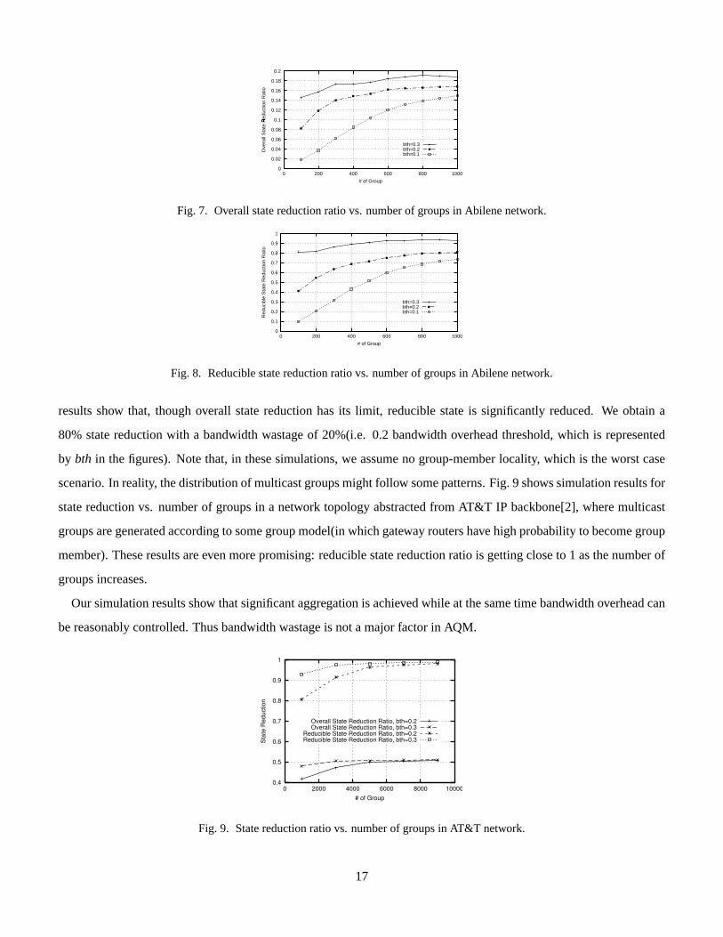
Fig. 7 and Fig. 8 plot the simulation results for overall state reduction ratio and reducible state reduction ratio vs.
number of groups in the Abilene[1] network core topology, where multicast groups are generated randomly. The
16
0
0.02
0.04
0.06
0.08
0.1
0.12
0.14
0.16
0.18
0.2
0 200 400 600 800 1000
Ove
rall
Sta
te R
educ
tion
Rat
io
�
# of Group
bth=0.3bth=0.2bth=0.1
Fig. 7. Overall state reduction ratio vs. number of groups in Abilene network.
0
0.1
0.2
0.3
0.4
0.5
0.6
0.7
0.8
0.9
1
0 200 400 600 800 1000
Red
ucib
le S
tate
Red
uctio
n R
atio
# of Group
bth=0.3bth=0.2bth=0.1
Fig. 8. Reducible state reduction ratio vs. number of groups in Abilene network.
results show that, though overall state reduction has its limit, reducible state is significantly reduced. We obtain a
80% state reduction with a bandwidth wastage of 20%(i.e. 0.2 bandwidth overhead threshold, which is represented
by bth in the figures). Note that, in these simulations, we assume no group-member locality, which is the worst case
scenario. In reality, the distribution of multicast groups might follow some patterns. Fig. 9 shows simulation results for
state reduction vs. number of groups in a network topology abstracted from AT&T IP backbone[2], where multicast
groups are generated according to some group model(in which gateway routers have high probability to become group
member). These results are even more promising: reducible state reduction ratio is getting close to 1 as the number of
groups increases.
Our simulation results show that significant aggregation is achieved while at the same time bandwidth overhead can
be reasonably controlled. Thus bandwidth wastage is not a major factor in AQM.
0.4
0.5
0.6
0.7
0.8
0.9
1
0 2000 4000 6000 8000 10000
Sta
te R
educ
tion
# of Group
Overall State Reduction Ratio, bth=0.2Overall State Reduction Ratio, bth=0.3
Reducible State Reduction Ratio, bth=0.2Reducible State Reduction Ratio, bth=0.3
Fig. 9. State reduction ratio vs. number of groups in AT&T network.
17

One way of reducing the wastage due to the “granularity” of the preconstructed trees is to use “tunneling” to
complement an “incomplete” tree as discussed in Section III. When a new multicast group request arrives, if the
tree manager can not find a proper existing tree to cover all the group members, instead of establishing a new tree, it
can choose the best “incomplete match”, i.e. the tree that covers the most, but not all, members of the group. Then
the tree manager notifies the uncovered members and their nearest ingress/egress routers of the “incomplete match”
tree. Between each uncovered group member and its corresponding ingress/egress router, a tunnel can be constructed
using unicast support directly. Note that, those tunneling-involved ingress/egress routers need to keep the state of
the multicast group. The tree manager periodically checks for the “incomplete match” multicast groups. If there are
“perfect match” aggregated trees for them, tree switching will be performed: the multicast groups leave their previous
trees and join their “perfect match” trees. And the corresponding tunnels are detached. We can see that this option is
another trade-off between state reduction and bandwidth wastage.
B. Benefits
While costs can be easily assessed with quantitative models, benefits are more difficult to measure in a precise
fashion. In the sequel, we discuss the potential benefits of the proposed solution.
• Main advantage is lower “state” storage and processing O/H at core routers.
• Other main advantage is faster forwarding (MPLS label vs. full multicast address indexing).
• Better use of network capacity by virtue of aggregation and of measurement based CAC.
• Easier set up of a group (minimal signaling required) and easier handling of nodes joining and leaving the group (no
need for explicit changes in the core router tables).
• Multiple aggregated trees can be maintained for different traffic classes (e.g. video conference, video lecture, internet
games, IP telephony, etc.). This way, the traffic in each tree is relatively homogeneous and easier to predict.
• Easier to multiplex different traffic types for same multicast group. For example, during videoconference, we may
exchange videoclips or PP presentations. This may be done using the extra bandwidth allocated to the primary tree,
or by using a parallel existing tree of different class. In the micro-flow, IntServ case, a new tree must be set up and
maintained for this purpose, again, more O/H.
VI. FUTUREWORK
We have introduced AQM, the architecture for scalable QoS multicast provisioning. We have identified the problems
in the design, especially the challenges brought on by bi-directional tree, and have given efficient and practical solution
for each of the problems. Our design shows that AQM is feasible and implementable based on the techniques available
in MPLS and Diff-Serv. In this section, we discuss some open issues which deserve further research or engineering
efforts.
18

A. Centralized Tree Manager
AQM relies on a centralized tree manager for tree management and resource management, which can be overloaded
and be a single point of failure. There are two ways of looking at this problem. First, a variety of systems, such
as clusters and processor groups, should be able to provide the processing power and speed required – considering
how amazingly many web servers scale up; at the same time, a distributed system can remedy the single point of
failure problem. On the other hand, such reliance is common in real life. Most core routers at prominent service
providers’ backbone networks can not fail without serious consequences. One may also argue that the problem of
requiring a tree manager is no worse than that of requiring a few RP routers in PIM-SM or a bandwidth broker in
DiffServ[6]. This discussion has its root in debate regarding centralized vs. decentralized multicast. In practices,
however, centralized approach is indeed adopted in multicast in ATM networks[22], and centralized tree calculation is
one possibility proposed in an MPLS multicast traffic engineering proposal[21].
B. Fault Tolerance of Bi-directional Aggregated Multicast Tree
In some applications (e.g. battlefield communications, distributed visualization and control, etc.), it is important
to provide fault tolerant multicast. For example, consider the control of a space launch carried out from different
ground stations interconnected by an Internet multicast tree. This control scenario may require the exchange of real
time, interactive data and streams. Fault tolerance is an even more critical issue in AQM architecture, because each
multicast tree is an aggregated tree, which is shared by several multicast groups. One way to provide fault tolerance
is the use of separate, possibly node disjoint multicast trees. For added reliability and zero switch-over latency, the
duplicate data could be sent on both trees simultaneously. However, this is a very straightforward and expensive
approach. Though there are some research efforts for the fault tolerance of unidirectional multicast tree, bi-directional
multicast tree brings another challenge.
C. A Special Case: Static Predefined Trees
In AQM, aggregated trees are established, changed (to add/remove nodes) or removed dynamically based on dy-
namic traffic monitoring. On the other hand, the set of aggregated trees can be established beforehand based on traffic
pattern from long-term measurements. Let us say, for example, measurements in MCI Worldcom’s national backbone
show that there are always many concurrent multicast sessions that involve three routers in Los Angeles, San Francisco
and New York. Based on that knowledge, a network operator can instruct the tree manager to setup an aggregated tree
covering routers in these three locations. Thus, within a domain, the ISP will offer a set of “static predefined” aggre-
gated trees and their corresponding MPLS trees will also be established beforehand. When a multicast group comes,
the tree manager will find a proper tree that best matches its current members configuration from all the installed
aggregated trees. As the membership grows, the groups can simply switch from one tree to another. Though this
19

special case looks simpler, it really depends on the predicability of the traffic pattern measurement. This case might
involve more bandwidth overhead, because “leaky match” between multicast groups and the static predefined trees
might happen more frequently.
VII. C ONCLUSIONS
In this report, we have presented an architecture, aggregated QoS multicast(AQM), for scalable QoS multicast pro-
visioning. In this architecture, we examine how we can use aggregated multicast to support QoS multicast efficiently
in Diff-Serv-Supported MPLS networks. We provide efficient and practical solutions for the critical issues in the AQM
deign. AQM is scalable, especially for QoS multicast provisioning in transit domains. Our design shows that AQM is
feasible and implementable based on the techniques of MPLS and Diff-Serv. Nowadays, many interactive, real time
applications such as video conferencing, distributed network games, distributed virtual collaborations (with real time
visualization and remote experiment steering), distance lectures with student participation are very attractive in our
everyday life. We believe that with the increasing demand of these applications, AQM will become a very promising
solution for scalable, real-time QoS multicast services in the Internet.
Work is continuing to refine AQM. And simulation efforts are underway, after which we can more realistically
evaluate and compare its performance and identify future deployment issues.
REFERENCES
[1] Abilene network topology.http://www.ucaid.edu/abilene/.
[2] AT&T IP Backbone.http://www.ipservices.att.com/backbone/, 2001.
[3] A. Ballardie, P. Francis, and J. Crowcroft. Core Based Trees (CBT).Proceedings of ACM SIGCOMM, pages 85–95, September 1993.
[4] A. Banerjea, M. Faloutous, and E. Crawley. QoSMIC: a quality of service sensitive multicast internet protocol.Internet draft: draft-
banerjea-qosmic-00.txt, October 1998.
[5] S. Biswas, R. Izmailov, and B. Rajagopalan. A QoS-aware routing framework for PIM-SM based IP-multicast.Internet draft: draft-
biswas-pim-sm-qos-00.txt, June 1999.
[6] S. Blake, D. Black, and et al. An architecture for Differentiated Services.IETF RFC 2475, 1998.
[7] R. Boivie, N. Feldman, Y. Imai, W. Livens, D. Ooms, and O. Paridaens. Explicit multicast (Xcast) basic specification.Internet draft:
draft-ooms-xcast-basic-spec-01.txt, March 2001.
[8] R. Braden, D. Clark, and S. Shenker. Integrated Services in the internet architecture: an overview.IETF RFC 1633, 1994.
[9] S. Deering, D. Estrin, D. Farinacci, V. Jacobson, C. Liu, and L. Wei. The PIM architecture for wide-area multicast routing.IEEE/ACM
Transactions on Networking, 4(2):153–162, April 1996.
[10] Le Faucheur and et al. MPLS support of Differentiated Services.Internet draft: draft-ietf-mpls-diff-ext-09.txt, April 2001.
[11] Aiguo Fei. Multicast routing with QoS constraints. PhD thesis, UCLA, June 2001.
[12] Aiguo Fei, Jun-Hong Cui, Mario Gerla, and Michalis Faloutsos. Aggregated multicast: an approach to reduce multicast state.To appear
in Sixth Global Internet Symposium(GI2001), November 2001.
[13] P. Francis. Yoid: extending the internet multicast architecture.http://www.aciri.org/yoid/docs/index.html.
20

[14] S. Ganti, N. Seddigh, and B. Nandy. MPLS support of Differentiated Services using E-LSP.Internet draft: draft-ietf-mpls-diff-ext-00.txt,
April 2001.
[15] J. Hou, H.-Y. Tyan, B. Wang, and Y.-M. Chen. QoS extension to CBT.Internet draft: draft-hou-cbt-qos-00.txt, February 1999.
[16] S. Jamin, P.B. Danzig, S. Shenker, and L. Zhang. A measurement-based admission control algorithm for integrated services packet
networks.Proceedings of ACM SIGCOMM’95, September 1995.
[17] Bilel Jamoussi and et al. Constraint-Based LSP set up using LDP.Internet draft: draft-ietf-mpls-cr-ldp05.txt, February 2001.
[18] U. Manber.Introduction to Algorithms: a Creative Approach. Addison-Wesley Publishing Company, 1989.
[19] J. Moy. Multicast routing extensions to OSPF.RFC 1584, March 1994.
[20] D. Ooms and et al. Framework for IP-multicast in MPLS.Internet draft: draft-ietf-mpls-multicast-05.txt, 2001.
[21] D. Ooms, R. Hoebeke, P. Cheval, and L. Wu. MPLS multicast traffic engineering.Internet draft: draft-ooms-mpls-multicast-te-00.txt,
2001.
[22] Radia Perlman.Interconnections: Bridges, Routers, Switches, and Internetworking Protocols. Addison-Wesley Publishing Company, 2nd
edition, October 1999.
[23] P. I. Radoslavov, D. Estrin, and R. Govindan. Exploiting the bandwidth-memory tradeoff in multicast state aggregation. Technical report,
USC Dept. of CS Technical Report 99-697 (Second Revision), July 1999.
[24] Y. Chu S. Rao and H. Zhang. A case for end system multicast.Proceedings of ACM Sigmetrics, June 2000.
[25] E. Rosen, A. Viswanathan, and R. Callon. Multiprotocol Label Switching Architecture.IETF RFC 3031, 2001.
[26] I. Stoica, T.S. Ng, and H. Zhang. REUNITE: A recursive unicast approach to multicast. InProceedings of IEEE INFOCOM’00, Tel Aviv,
Israel, March 2000.
[27] D. Thaler and M. Handley. On the aggregatability of multicast forwarding state.Proceedings of IEEE INFOCOM, March 2000.
[28] J. Tian and G. Neufeld. Forwarding state reduction for sparese mode multicast communications.Proceedings of IEEE INFOCOM, March
1998.
[29] L. Zhang, S. Deering, D. Estrin, S. Shenker, and D. Zappala. RSVP: a new resource reservation protocol.IEEE Network, September 1993.
21