robotics applicationmanual conveyortracking...overviewofthismanual aboutthismanual...
TRANSCRIPT

ROBOTICS
Application manualConveyor tracking

Trace back information:Workspace R18-2 version a10Checked in 2018-10-10Skribenta version 5.3.008
Application manualConveyor tracking
RobotWare 6.08
Document ID: 3HAC050991-001Revision: G
© Copyright 2004-2018 ABB. All rights reserved.Specifications subject to change without notice.

The information in this manual is subject to change without notice and should notbe construed as a commitment by ABB. ABB assumes no responsibility for any errorsthat may appear in this manual.Except as may be expressly stated anywhere in this manual, nothing herein shall beconstrued as any kind of guarantee or warranty by ABB for losses, damages topersons or property, fitness for a specific purpose or the like.In no event shall ABB be liable for incidental or consequential damages arising fromuse of this manual and products described herein.This manual and parts thereof must not be reproduced or copied without ABB'swritten permission.Keep for future reference.Additional copies of this manual may be obtained from ABB.
Original instructions.
© Copyright 2004-2018 ABB. All rights reserved.Specifications subject to change without notice.
ABB AB, RoboticsRobotics and MotionSe-721 68 Västerås
Sweden

Table of contents9Overview of this manual ...................................................................................................................
11Product documentation ....................................................................................................................13Safety ................................................................................................................................................
151 Introduction to conveyor tracking151.1 Physical components .........................................................................................171.2 Features ..........................................................................................................191.3 Limitations .......................................................................................................201.4 Principles of conveyor tracking ............................................................................
252 Conveyor tracking modules (CTMs)252.1 Network based conveyor tracking module CTM-01, DSQC2000 ..................................372.2 DeviceNet based conveyor tracking unit DSQC377B ................................................
393 Installation393.1 Hardware connections .......................................................................................403.2 Installing the encoder for conveyor tracking ...........................................................423.2.1 Encoder location .....................................................................................433.2.2 Encoder cables .......................................................................................443.3 Connecting the encoder to the CTM-01, DSQC2000 .................................................483.4 Connecting the encoder to the DSQC377B .............................................................513.5 Connecting a camera to the CTM-01, DSQC2000 ....................................................523.6 Connecting the sync switches to the CTM-01, DSQC2000 .........................................
534 Conveyor Tracking tab in RobotStudio
615 Configuration and calibration615.1 About software installation and configuration .........................................................625.2 Configuration of tracking unit DSQC2000 ...............................................................655.3 Verifying the installation of encoders and sensors (DSQC2000 only) ...........................675.4 Configuration of robot controllers (DSQC2000 only) .................................................705.5 Direction of positive motion from the encoder (DSQC377 only) ..................................715.6 Calibrating CountsPerMeter (DSQC377) ................................................................725.7 Calibrating CountsPerMeter (DSQC2000) ..............................................................735.8 Calibrating the conveyor base frame .....................................................................765.9 Defining conveyor start window and sync separation ...............................................775.10 Avoiding robot reach problems ............................................................................785.11 Using a trigger output on the DSQC2000 ...............................................................795.12 Defining the robot adjustment speed .....................................................................805.13 Additional adjustments .......................................................................................815.14 Configuring a track motion to follow a conveyor ......................................................835.15 Installing conveyor tracking software ....................................................................845.16 Installing additional conveyors work areas for conveyor tracking ................................
876 Programming876.1 Programming conveyor tracking ..........................................................................886.2 Working with the object queue .............................................................................896.3 Activating the conveyor ......................................................................................906.4 Defining a conveyor coordinated work object .........................................................916.5 Waiting for a work object ....................................................................................926.6 Programming the conveyor coordinated motion ......................................................936.7 Dropping a work object ......................................................................................946.8 Entering and exiting conveyor tracking motion in corner zones ..................................956.9 Information on FlexPendant ................................................................................966.10 Programming considerations ...............................................................................
Application manual - Conveyor tracking 53HAC050991-001 Revision: G
© Copyright 2004-2018 ABB. All rights reserved.
Table of contents

976.11 Finepoint programming ......................................................................................986.12 Operating modes ..............................................................................................
997 System parameters997.1 Introduction ......................................................................................................
1007.2 Topic I/O ..........................................................................................................1017.3 Topic Process ..................................................................................................1047.4 Topic Motion ....................................................................................................
1078 RAPID reference1078.1 Instructions ......................................................................................................1078.1.1 WaitWObj - Wait for work object on conveyor ...............................................1108.1.2 DropWObj - Drop work object on conveyor ...................................................1118.1.3 UseReachableTargets - Use reachable targets ..............................................1148.1.4 GetMaxUsageTime - Get max measured usage time ......................................1158.1.5 ResetMaxUsageTime - Reset max measured usage time ................................1168.1.6 CnvPredictReach - High speed conveyors ...................................................
1219 Advanced queue tracking1219.1 Introduction to advanced queue tracking ...............................................................1239.2 Working with the object queue .............................................................................
12710 Circular conveyor tracking12710.1 Introduction to circular conveyor tracking ..............................................................12910.2 Encoder type selection and location .....................................................................13010.3 Installation and configuration ...............................................................................13110.4 Additional motion settings ...................................................................................13210.5 Calibrating the conveyor base frame .....................................................................13310.6 Manually calibrating the conveyor base frame ........................................................13410.7 TCP measurement method .................................................................................
13711 Accelerating conveyors13711.1 Introduction to accelerating conveyors ..................................................................13811.2 System parameters ...........................................................................................14011.3 Predicting speed changes ...................................................................................14111.4 UseAccProfile - Use acceleration profile ................................................................
14512 Indexing conveyors14512.1 Description of indexing conveyor options ..............................................................14612.2 Tracking indexing conveyors ...............................................................................14612.2.1 Setting up tracking for an indexing conveyor ................................................14712.2.2 System parameters .................................................................................14812.2.3 Replacing the xx ....................................................................................14912.2.4 RecordProfile .........................................................................................15012.2.5 WaitAndRecProf .....................................................................................15212.2.6 StoreProfile ............................................................................................15312.2.7 LoadProfile ............................................................................................15412.2.8 ActivateProfile ........................................................................................15512.2.9 DeactProfile ...........................................................................................15612.2.10 CnvGenInstr ...........................................................................................15912.3 Indexing conveyor with servo control (Indexing Conveyor Control) .............................15912.3.1 Introduction to indexing conveyors with servo control ....................................16212.3.2 Setting up a servo controlled indexing conveyor ...........................................16312.3.3 System parameters and configuration files ...................................................16812.3.4 Testing the indexing conveyor setup ...........................................................16912.3.5 Calibrating the base frame ........................................................................17012.3.6 indcnvdata .............................................................................................
6 Application manual - Conveyor tracking3HAC050991-001 Revision: G
© Copyright 2004-2018 ABB. All rights reserved.
Table of contents
17112.3.7 IndCnvInit ..............................................................................................17212.3.8 IndCnvEnable and IndCnvDisable ..............................................................17312.3.9 IndCnvReset ..........................................................................................17412.3.10 IndCnvAddObject ....................................................................................17512.3.11 RAPID programming example ....................................................................17812.3.12 Minimizing trigger time .............................................................................
17913 Conveyor tracking and MultiMove17913.1 About conveyor tracking and MultiMove ................................................................18113.2 Configuration example for UnsyncCnv ..................................................................18313.3 Configuration example for SyncCnv ......................................................................18513.4 Tasks and programming techniques .....................................................................18713.5 Independent movements, example UnsyncCnv .......................................................18913.6 Coordinated synchronized movements, example SyncCnv ........................................19213.7 Motion principles ...............................................................................................19313.8 Combining synchronized and un-synchronized mode ...............................................
19514 Troubleshooting19514.1 Overview .........................................................................................................19614.2 Event messages ...............................................................................................19914.3 System parameters ...........................................................................................20014.4 Robot path characteristics ..................................................................................20214.5 Power failure ....................................................................................................20314.6 Collision detection .............................................................................................20414.7 Technical support ..............................................................................................
205Index
Application manual - Conveyor tracking 73HAC050991-001 Revision: G
© Copyright 2004-2018 ABB. All rights reserved.
Table of contents

This page is intentionally left blank

Overview of this manualAbout this manual
This manual describes the optionsConveyor Tracking, Indexing Conveyor Control,and Tracking Unit Interface for IRC5. Conveyor tracking, or line tracking, is whenthe robot follows a work object mounted on a moving conveyor.The option Indexing Conveyor Control is used when the servo for an indexingconveyor is controlled by the IRC5 controller.The Tracking Unit Interface is used to establish communication with a remoteConveyor Tracking Module.
UsagesThe manual describes how the options are installed, programmed, and operated.
ReferencesThe manual contains references to the following information products:
Document IDReferences
3HAC021313-001Product manual - IRC5IRC5 with main computer DSQC 639.
3HAC047136-001Product manual - IRC5IRC5 with main computer DSQC1000.
3HNA008861-001Product Manual - IRC5P
note: dummy manualInstallation manual - IRC5P RW 6.0
3HAC050941-001Operating manual - IRC5 with FlexPendant
3HNA008861-001Operator's Manual - IRC5P
3HAC032104-001Operating manual - RobotStudio
3HAC050948-001Technical reference manual - System parameters
3HAC050917-001Technical reference manual - RAPID Instructions, Functions andData types
3HAC050947-001Technical reference manual - RAPID Overview
3HAC051016-001Application manual - Additional axes and stand alone controller
3HAC050798-001Application manual - Controller software IRC5
3HAC050961-001Application manual - MultiMove
3HAC050992-001Application manual - DeviceNet Master/Slave
3HAC050940-001Operating manual - IRC5 Integrator's guide
3HAC031978-001Application manual - PickMaster 3
RevisionsThe following revisions of this manual have been released.
DescriptionRevision
Released with RobotWare 6.0.-
Continues on next pageApplication manual - Conveyor tracking 93HAC050991-001 Revision: G
© Copyright 2004-2018 ABB. All rights reserved.
Overview of this manual

DescriptionRevision
Released with RobotWare 6.01.• Updated information about adding conveyor tracking to an existing robot
system, see Installing conveyor tracking software on page 83.
A
Released with RobotWare 6.03.BAdded information about the system parameter Supervise max_dist Off insection Avoiding robot reach problems on page 77.
Released with RobotWare 6.04.• Updated the counter values from 16-bit signals to 32-bit signals, see
System parameters on page 121.• Minor corrections.
C
Released with RobotWare 6.05.• Minor corrections.
D
Released with RobotWare 6.06.• Added the chapter Troubleshooting on page 195
E
Released with RobotWare 6.07.• Updates and added the CnvPredictReach - High speed conveyors on
page 116 chapter.
F
Released with RobotWare 6.08.• Minor corrections.• Added Buttons section and minor changes to the LED indicators section,
in chapter Conveyor tracking modules (CTMs) on page 25 and addedIdentifying a CTM in RobotStudio on page 54.
• Minor corrections in Introduction to conveyor tracking on page 15,Features section.
• Updated recommendations in Encoder cables on page 43.
G
10 Application manual - Conveyor tracking3HAC050991-001 Revision: G
© Copyright 2004-2018 ABB. All rights reserved.
Overview of this manualContinued

Product documentationCategories for user documentation from ABB Robotics
The user documentation from ABB Robotics is divided into a number of categories.This listing is based on the type of information in the documents, regardless ofwhether the products are standard or optional.All documents can be found via myABB Business Portal, www.myportal.abb.com.
Product manualsManipulators, controllers, DressPack/SpotPack, and most other hardware isdelivered with a Product manual that generally contains:
• Safety information.• Installation and commissioning (descriptions of mechanical installation or
electrical connections).• Maintenance (descriptions of all required preventive maintenance procedures
including intervals and expected life time of parts).• Repair (descriptions of all recommended repair procedures including spare
parts).• Calibration.• Decommissioning.• Reference information (safety standards, unit conversions, screw joints, lists
of tools).• Spare parts list with corresponding figures (or references to separate spare
parts lists).• References to circuit diagrams.
Technical reference manualsThe technical reference manuals describe reference information for roboticsproducts, for example lubrication, the RAPID language, and system parameters.
Application manualsSpecific applications (for example software or hardware options) are described inApplication manuals. An application manual can describe one or severalapplications.An application manual generally contains information about:
• The purpose of the application (what it does and when it is useful).• What is included (for example cables, I/O boards, RAPID instructions, system
parameters, software).• How to install included or required hardware.• How to use the application.• Examples of how to use the application.
Continues on next pageApplication manual - Conveyor tracking 113HAC050991-001 Revision: G
© Copyright 2004-2018 ABB. All rights reserved.
Product documentation

Operating manualsThe operating manuals describe hands-on handling of the products. The manualsare aimed at those having first-hand operational contact with the product, that isproduction cell operators, programmers, and troubleshooters.
12 Application manual - Conveyor tracking3HAC050991-001 Revision: G
© Copyright 2004-2018 ABB. All rights reserved.
Product documentationContinued

SafetySafety of personnel
When working inside the robot controller it is necessary to be aware ofvoltage-related risks.A danger of high voltage is associated with the following parts:
• Devices inside the controller, for example I/O devices, can be supplied withpower from an external source.
• The mains supply/mains switch.• The power unit.• The power supply unit for the computer system (230 VAC).• The rectifier unit (400-480 VAC and 700 VDC). Capacitors!• The drive unit (700 VDC).• The service outlets (115/230 VAC).• The power supply unit for tools, or special power supply units for the
machining process.• The external voltage connected to the controller remains live even when the
robot is disconnected from the mains.• Additional connections.
Therefore, it is important that all safety regulations are followed when doingmechanical and electrical installation work.
Safety regulationsBefore beginning mechanical and/or electrical installations, ensure you are familiarwith the safety regulations described in Operating manual - General safetyinformation1 .
1 This manual contains all safety instructions from the product manuals for the manipulators and the controllers.
Application manual - Conveyor tracking 133HAC050991-001 Revision: G
© Copyright 2004-2018 ABB. All rights reserved.
Safety

This page is intentionally left blank

1 Introduction to conveyor tracking1.1 Physical components
Option Conveyor TrackingA typical installation when using the optionConveyor Tracking includes the followingcomponents:
IRB
A B
C
D
E
xx1200001074
Synchronization switchA
ConveyorB
Encoder, 24 VC
Encoder interfaceD
IRC5 controllerE
RobotIRB
The encoder and synchronization switch are connected to the encoder interface.If using the encoder interface unit DSQC377B and more than one robot shouldtrack the conveyor, then each robot must have an encoder interface unit. Oneencoder can then can be connected to several encoder interfaces.
Option Indexing Conveyor ControlA typical installation when using the option Indexing Conveyor Control includesthe following components:
IRB
A
B
C
D
E
xx1200001075
Continues on next pageApplication manual - Conveyor tracking 153HAC050991-001 Revision: G
© Copyright 2004-2018 ABB. All rights reserved.
1 Introduction to conveyor tracking1.1 Physical components

InfeederA
SensorB
Motor unitC
Indexed conveyorD
IRC5 controllerE
IRB robotIRB
An extra drive unit and SMB needs to be installed, see Applicationmanual - Additional axes and stand alone controller.
16 Application manual - Conveyor tracking3HAC050991-001 Revision: G
© Copyright 2004-2018 ABB. All rights reserved.
1 Introduction to conveyor tracking1.1 Physical componentsContinued

1.2 Features
AccuracyIn automatic mode, at 150 mm/s constant conveyor speed, the tool center point(TCP) of the robot will stay within +/- 2 mm of the path. This distance is maintainedwhether the conveyor is in motion or not. This is valid as long as the robot is withinits dynamic limits with the added conveyor motion. This figure depends on thecalibration of the robot and conveyor and is applicable for linear conveyor trackingonly.
Object queueFor the option Conveyor Tracking, a queue is maintained of up to 254 objects thathave passed the synchronization switch. For the option Indexing Conveyor Control,the queue can contain up to 100 objects.
Start windowA program can choose to wait for an object that is within a window past the normalstarting point, or wait for an object to pass a specific distance, or immediately takethe first object in the object tracking queue. Objects that go beyond the start windoware automatically skipped.
RAPID access to queue and conveyor dataA RAPID program has access to the number of objects in the object queue, andthe current position and speed of the conveyor. A RAPID program can also removethe first object in the tracking queue or all objects in the queue.
Maximum distanceA maximum tracking distance can be specified to stop the robot from trackingoutside of the working or safety area.
Track follows conveyorIf the robot is mounted on a linear track, then the system can be configured so thatthe track will follow the conveyor and maintain the relative position to the conveyor.The TCP speed relative the work object on the conveyor will still be the programmedspeed.
Enter and exit conveyor tracking in corner zonesIt is possible to enter and exit conveyor tracking via corner zones as well as viafine points. Use corner zones to achieve a minimum cycle time.
Exit and re-enter conveyor tracking to same objectIt is possible to exit and re-enter to the same object on the conveyor unlimitedtimes until the object moves outside the working area, reaches the maximumdistance, or is explicitly dropped by the RAPID program.
Continues on next pageApplication manual - Conveyor tracking 173HAC050991-001 Revision: G
© Copyright 2004-2018 ABB. All rights reserved.
1 Introduction to conveyor tracking1.2 Features
Multiple conveyorsUp to six conveyors are supported with the optionConveyor Tracking. Each encodermust be connected to an encoder interface.Up to two indexed conveyors can be used with the option Indexing ConveyorControl.
Coordinated finepointA finepoint can be programmed while moving relative to the conveyor. This conveyorcoordinated finepoint will ensure that the robot stops moving relative to the conveyorand will follow the conveyor while the RAPID program continues execution. Therobot will hold the position within +/- 0.7 mm depending on calibration of the robotand conveyor.
Calibration of linear conveyorsA calibration method is provided for easy calibration of the position and directionof the conveyor motion in the robot work space. The linear conveyor may take anyposition and orientation.
18 Application manual - Conveyor tracking3HAC050991-001 Revision: G
© Copyright 2004-2018 ABB. All rights reserved.
1 Introduction to conveyor tracking1.2 FeaturesContinued
1.3 Limitations
Small orientation error with SingArea\WristThere can be a small orientation error of the TCP while following the conveyor andmake long motions with SingArea\Wrist. This error can be eliminated by usingseveral short movements with SingArea\Wrist.
Robot mounted on trackIf the robot is mounted on a track and the track is to be used to follow the conveyormotions, then the track and conveyor must be parallel.The motion on the track and the motion on the conveyor must have the samedirection of positive motion. See Configuring a track motion to follow a conveyoron page 81.
Calibrating circular conveyorsThere are no built-in methods for calibrating circular conveyors. This can be evadedby calculating a quaternion orientation manually or with other tools during baseframe calibration.
Additional axesFor the option Conveyor Tracking, each conveyor is considered an additional axis.Thus the system limitation of 6 active additional axes must be reduced by thenumber of active and installed conveyors.The first installed conveyor will use measurement node 6 and the second conveyorwill use measurement node 5. These measurement nodes are not available foradditional axes and no resolvers should be connected to these nodes on anyadditional axes measurement boards.For the option Indexing Conveyor Control, each conveyor is considered as twoadditional axes.
Object queue lost on restart or power failureIf the system is restarted or if the power supply fails, then the object queue will belost.
Minimum and maximum speedThe minimum conveyor speed to maintain smooth and accurate motions dependson the encoder selection. It can vary from 4 mm/s to 8 mm/s. See Minimum andmaximum counts per second on page 41.There is no explicit maximum speed for the conveyor. Accuracy will degrade atspeeds above the specification and with high speed robot motions or with veryhigh conveyor speeds (> 500 mm/s) and the robot will no longer be able to followthe conveyor.
WaitWObj after DropWObjIf a WaitWObj instruction is used immediately after a DropWObj instruction, it maybe necessary to add a WaitTime 0.1; after the DropWObj instruction.
Application manual - Conveyor tracking 193HAC050991-001 Revision: G
© Copyright 2004-2018 ABB. All rights reserved.
1 Introduction to conveyor tracking1.3 Limitations

1.4 Principles of conveyor tracking
DescriptionIn conveyor tracking, the robot Tool Center Point (TCP) will automatically follow awork object that is defined on the moving conveyor. While tracking the conveyorthe IRC5 will maintain the programmed TCP speed relative to the work object evenif the conveyor runs at different speeds.The options Conveyor Tracking and Indexing Conveyor Control are built on thecoordinated work object, as with coordinated motion with additional axes. SeeApplication manual - Additional axes and stand alone controller.
Conveyor as a mechanical unitIn the option Conveyor Tracking, the conveyor is treated as a mechanical unit. Ithas all features of a mechanical unit except that it is not controlled by the IRC5controller. In the option Indexing Conveyor Control, the conveyor is treated as amechanical unit and controlled by the IRC5 controller.As a mechanical unit, the conveyor can be activated and deactivated. The positionof the conveyor is shown on the FlexPendant Joggingwindow, and in the robtargetwhen a position is modified (ModPos).
Conveyor coordinated work objectThe robot movements are coordinated to the movements of a user frame connectedto the conveyor mechanical unit. For example a user frame is placed on theconveyor and connected to its movements.A movable work object is used with the name of the conveyor mechanical unit.The conveyor tracking coordination will be active if the mechanical unit is activeand the conveyor coordinated work object is active. When the conveyor coordinatedwork object is used, in jogging or in a move instruction, the data in the uframecomponent will be ignored and the location of the user coordinate system will onlydepend on the movements of the conveyor mechanical unit. However the oframecomponent will still work giving an object frame related to the user frame and alsothe displacement frame can be used.
Waiting for a work object on the conveyorThe difference between a conveyor coordinated work object and a work object thatis coordinated to another type of mechanical unit is that there is no work objectfor coordination until an object appears on the conveyor. There must be a workobject present on the conveyor before the robot can coordinate the TCP positionsto the conveyor.For the option Conveyor Tracking, work objects on the conveyor are detected bythe synchronization switch that is connected to the encoder interface. The unittracks all objects that have past the synchronization switch and are within specifieddistances in the work area.For the option Indexing Conveyor Control, the work object is created when thedefined number of objects (that is, number of indexes) have passed. Before startingcoordinated motion with the conveyor, the RAPID program must first check if there
Continues on next page20 Application manual - Conveyor tracking
3HAC050991-001 Revision: G© Copyright 2004-2018 ABB. All rights reserved.
1 Introduction to conveyor tracking1.4 Principles of conveyor tracking

is a work object available on the conveyor. If an object is available then executioncontinues and the motions can use the coordinated work object. If there is noobject, then the RAPID program waits until a work object is available.
Connecting to a work objectThe RAPID instruction WaitWObj is used to wait for a work object on the conveyorbefore starting conveyor coordinated motion. When the WaitWObj instruction issuccessful then the conveyor work object is said to be connected to the RAPIDprogram. See WaitWObj - Wait for work object on conveyor on page 107.Once a RAPID program has connected to a work object on the conveyor then robotmotion instructions and jogging commands can use this work object just as anyother work object. When using the conveyor connected coordinated work objectthen all motions are relative to the work object on the conveyor.The robot can switch between the conveyor coordinated work object and anothercoordinated work object in the system, but only one conveyor work object can beconnected.
Disconnecting from a work objectThe work object will remain connected until one of the following occurs:
• A DropWObj instruction is issued• The maximum distance defined for the conveyor is reached• Controller is restarted• Power failure
The connection to the work object will not be lost when deactivating the conveyormechanical unit, and will return on re-activation.The instruction DropWObj ends the connection before the maximum distance isreached.After a DropWObj instruction is issued it is possible to immediately wait for andconnect to the next work object in the conveyor object queue.
Start window and queue tracking distanceThe object queue is based on a set of distances relative to the conveyor andsynchronization switch. See the following figure.
A
C
F G
D E
B
z y
x1234567
xx1200001076
Synchronization switchA
Work object user frameB
Minimum distance (minimum distance)C
Continues on next pageApplication manual - Conveyor tracking 213HAC050991-001 Revision: G
© Copyright 2004-2018 ABB. All rights reserved.
1 Introduction to conveyor tracking1.4 Principles of conveyor tracking
Continued

Start window width (StartWinWidth)D
Working areaE
Queue tracking distance (QueueTrckDist)F
Maximum distance (maximum distance)G
Objects on conveyor1-7
The conditions and states of objects 1 to 7 can be described as in the followingtable.For descriptions of the system parameters StartWinWidth and QueueTrckDist seeType Fieldbus Command (DSQC377 only) on page 100. For descriptions of thesystem parameters minimum distance and and maximum distance see TypeConveyor systems on page 101.
DescriptionObjects
This object is connected as indicated by the coordinate frame attached to theposition of the object on the conveyor.
1
Object 2 is outside the start window and is no longer tracked. This object willbe skipped and cannot be connected by a WaitWObj instruction. It is skippedbecause the conveyor speed is such that coordination with the object couldnot be completed before the object moves outside the maximum distance orwork area of the robot.
2
These objects are within the start window and are tracked. If object 1 is and 4dropped via a DropWObj instruction then object 3 is the next object to be con-nected when a WaitWObj instruction is issued. Because objects 3 and 4 werein the start window, the WaitWObj instruction will not wait but return immediatelywith object 3.
3 and 4
These objects lie within the queue tracking distance and are tracked. If objectsand 6, 3, and 4 were not present, then a WaitWObj instruction would stop pro-gram execution until object 5 entered the start window.
5 and 6
This object has not yet passed the synchronization switch and has not yet beenregistered.
7
Continues on next page22 Application manual - Conveyor tracking
3HAC050991-001 Revision: G© Copyright 2004-2018 ABB. All rights reserved.
1 Introduction to conveyor tracking1.4 Principles of conveyor trackingContinued

Coordinate systems
A
E
G H
F
J
B C
D
z y
x
z y
xz y
x
z y
x
K
z
yx
0.0 m
xx1200001077
Synchronization switchA
Base frame for conveyorB
User frameC
Object frameD
Minimum distanceE
Start window widthF
Queue tracking distanceG
Maximum distanceH
World frameJ
Base frame for robotK
The preceding figure shows the principle coordinate frames used in conveyortracking. See the following table.
Relative toCoordinate system
World frameBase frame of robot
N.a.World frame
World frameBase frame of conveyor
World frame via base frame of conveyorUser frame, coordinated to conveyor
User frameObject frame (not shown)
Key frames and positionsThe two key frames in conveyor tracking are the base frame for the conveyor andthe user frame in the conveyor coordinated work object. The position of user framein the conveyor coordinated work object is determined from the position of theconveyor base frame and the linear position of the conveyor in meters.The encoder interface provides the position of the conveyor relative thesynchronization switch and the Queue Tracking Distance. When the conveyorposition is 0.0 meters, the user frame for the conveyor coordinated work object
Continues on next pageApplication manual - Conveyor tracking 233HAC050991-001 Revision: G
© Copyright 2004-2018 ABB. All rights reserved.
1 Introduction to conveyor tracking1.4 Principles of conveyor tracking
Continued
coincides with the base frame of the conveyor. As the conveyor moves, then theuser frame in the conveyor coordinated work object moves along the x-axis of theconveyor base frame.See Operating manual - IRC5 with FlexPendant and Technical reference manual -RAPID Overview.
24 Application manual - Conveyor tracking3HAC050991-001 Revision: G
© Copyright 2004-2018 ABB. All rights reserved.
1 Introduction to conveyor tracking1.4 Principles of conveyor trackingContinued

2 Conveyor tracking modules (CTMs)2.1 Network based conveyor tracking module CTM-01, DSQC2000
DescriptionThe CTM-01 is a network based conveyor interface that provides connections for4 encoders and 8 cameras.
xx1800000346
The CTM-01 uses network communication to share conveyor speed and positiondata with one or more robot controllers. It contains a WAN port, which is used toconnect to the robot controllers and two LAN ports that can be used for installationand service purposes. It can be located either inside the robot controller or insidea separate cabinet. To improve the quality of the signals keep the CTM close tothe encoders and the sensors.Each of the encoder inputs support one 2 phase encoder. Each of the cameraconnections consist of a digital sync input, a 24 V digital trigger output, and acamera power output. The camera connection can also be used for other syncinput sources, for example photocells.
Continues on next pageApplication manual - Conveyor tracking 253HAC050991-001 Revision: G
© Copyright 2004-2018 ABB. All rights reserved.
2 Conveyor tracking modules (CTMs)2.1 Network based conveyor tracking module CTM-01, DSQC2000

Functions
Ethernet connectionsThe CTM includes WAN and LAN Ethernet ports. The WAN port of the CTM mustbe connected to the same Ethernet network as the robot controllers. The robotcontrollers should be connected to the same network with their WAN or LAN 3ports. If the CTM is only used by one robot controller, for example an internallymounted CTM, the WAN port of the CTM should be connected to the LAN 2, LAN3, or WAN port of the robot controller through a switch.
Power distributionsThe CTM has two power inlets, power inlet (X1) and an optional camera powerinlet (X20). The power inlet is 24 V, it supplies power to all main function on theCTM module, as shown in the following figure:
xx1800000347
The Camera power (X20) and its ground connection are separated from the restof the CTM power. The camera power can only be routed from the power inletthrough the CTM's current protection circuits to the individual outputs in the cameraconnectors (X21-X28), as shown in the following figure:
xx1800000348
The 24V_INP, 24VDC, CAM_PWR, and 3V3 are covered by diagnostics functionsand their levels are displayed in RobotStudio.
Continues on next page26 Application manual - Conveyor tracking
3HAC050991-001 Revision: G© Copyright 2004-2018 ABB. All rights reserved.
2 Conveyor tracking modules (CTMs)2.1 Network based conveyor tracking module CTM-01, DSQC2000Continued

Encoder power outputsEach encoder connection (X11 - X14) supports an encoder power output. Theencoder power output is 24 V with diagnostics functions, which is controlled by ahigh side driver circuit. In case of an overload or short circuit on the CTM, it isturned off. This output also contains a Discovery function, which can detect if anencoder is connected to the power. A constant test current of approximately 5 uAchecks the output of the Discovery function, if the output is off it is activated. Thistest current will cause an unconnected trigger output pin to float at 10 V, evenwhen the output signal is turned off. This power output is always on, except duringstartup, as shown in the following figure:
xx1800000349
Encoder inputsEach encoder connection (X11-X14) supports a two phase encoder. The inputsare isolated and open ended to support NPN, PNP, and Push-Pull type encoders.The encoder can be powered from the CTM or by an external power supply, asshown in the following figure:
xx1800000350
Continues on next pageApplication manual - Conveyor tracking 273HAC050991-001 Revision: G
© Copyright 2004-2018 ABB. All rights reserved.
2 Conveyor tracking modules (CTMs)2.1 Network based conveyor tracking module CTM-01, DSQC2000
Continued

Sync inputsEach camera connector (X21 - X28) has a sync input which is isolated throughopto couplers. These couplers are single ended, share a common GND with theCTM board, and support PNP and push-pull sensors. It is recommended to usethe sync power output to power the sync sensor signal, as shown in the followingfigure:
xx1800000351
Trigger outputsEach camera connector (X21 - X28) has a trigger output. This output is a 24 Vdigital output with diagnostics functions, which is controlled by a high side drivercircuit. In case of an overload or short circuit on the CTM, it is turned off. Thisoutput also contains a Discovery function, which can detect if an encoder isconnected to the power. A constant test current of approximately 5 uA checks theoutput of the Discovery function, if the output is off it is activated. This test currentwill cause an unconnected trigger output pin to float at 10 V, even when the outputsignal is turned off.The following figure shows a drawing of the trigger output.
xx1800000352
Technical specification DSQC2000, CTM-01
General
24 VDC (-15/+20%), typically 200 mAPower supply(Current not including power outputs)
Continues on next page28 Application manual - Conveyor tracking
3HAC050991-001 Revision: G© Copyright 2004-2018 ABB. All rights reserved.
2 Conveyor tracking modules (CTMs)2.1 Network based conveyor tracking module CTM-01, DSQC2000Continued

General
+5°C - +65°COperating temperature
2 switched LAN ports, 100 Mbit (Only for installationand service purposes )
Ethernet LAN
1 WAN port, 100 MbitEthernet WAN
4 pcs (X11-X14)Encoders
24 VDC, max 120 mAPower outputWith connection discovery and overload protection/dia-gnostic
0 - 20 kHzFrequency
5.2 mA at 24 VDCInput current
15 VDC < '1' < 30 VDC, -3 VDC< '0' < 5 VDCVoltage levels
PNP, NPN, and Push-PullSupported encoder types
8 pcs (X21-X28)Cameras
Supplied from X20 camera power inletCamera power output(normally 24 VDC, maximum 250 mA)With overload protection
Sync input signal
24 VDC, 120 mAPower outputWith connection discovery and overload protection/dia-gnostic
5.2 mA at 24 VDCInput Current
15 VDC < '1' < 30 VDC, -3 VDC< '0' < 5 VDCVoltage levels
PNP and Push-PullSupported Encoder types
Trigger output
24 VDC, Max 120 mADigital outputWith connection discovery and overload protection/dia-gnostic
0.1 mAMinimum load(Floating pins will drift towards voltage rails)
LED indicatorsThe CTM module has the following LED diagnostics and information:
• Module Status LED – BiColor LED displays the module status.
Continues on next pageApplication manual - Conveyor tracking 293HAC050991-001 Revision: G
© Copyright 2004-2018 ABB. All rights reserved.
2 Conveyor tracking modules (CTMs)2.1 Network based conveyor tracking module CTM-01, DSQC2000
Continued

DescriptionStatus LED
During startup• Red (steady): Default at power up
xx1800000353
OS loading• Red (blinking): Startup completed OK
Run-time• Green (steady): Up and running, OS
loading completed OK
• Module Discovery LED – Indicates the connection status of the CTM modulewith a RobotStudio client.
DescriptionDiscovery LED
LED_SW1 (1 - 2)• Green (blinking): Connected and selec-
ted by a RobotStudio client.
xx1800001604
• On the CPU board, there are three Ethernet connection status LEDs and aLED displaying the power status.
DescriptionEthernet Link Status
LED 1 - Ethernet LAN 1 LED• Green LED: Ethernet LAN 1, 100 Mbit
link enabled• Ethernet port 1, Connector X5
xx1800000354
LED 2 - Ethernet LAN 2 LED• Green LED: Ethernet LAN 2, 100 Mbit
link enabled• Ethernet port 2, Connector X6
LED 3 - Ethernet WAN port LED• Green LED: Ethernet WAN, 100M bit
link enabled• Ethernet port 3, Connector X7
Continues on next page30 Application manual - Conveyor tracking
3HAC050991-001 Revision: G© Copyright 2004-2018 ABB. All rights reserved.
2 Conveyor tracking modules (CTMs)2.1 Network based conveyor tracking module CTM-01, DSQC2000Continued

DescriptionCPU board power status
LED 4 - Power Status• Green LED: 3.3 VDC power is OK
xx1800000355
• Each encoder input has two status LEDs, one for each input pair.
DescriptionCPU board power status
LED_ENC (1 - 4) A & B LEDs
xx1800000356
For each encoder connection (X11 - X14)there is a LED displaying the input level ofeach encoder pair.
• A LED displaying the status of the camera power inlet.
DescriptionCamera power status LED
LED_CAM_PWR
xx1800000357
Displays the power status of the optionalcamera power inlet.
Continues on next pageApplication manual - Conveyor tracking 313HAC050991-001 Revision: G
© Copyright 2004-2018 ABB. All rights reserved.
2 Conveyor tracking modules (CTMs)2.1 Network based conveyor tracking module CTM-01, DSQC2000
Continued

• Each camera connection has two status LEDs, one for the sync signal inputand one for the trigger signal output.
DescriptionCamera status LED
LED_SYNC (1 - 8) LEDs
xx1800000358
For each camera connection (X21 - X28) thereis a LED displaying the input stage of thesync input signal.
LED_Trig (1 - 8) LEDsFor each camera connection (X21 - X28) thereis a LED displaying the output stage of thetrigger output signal.
ButtonsThe CTM module has the following two user interactive buttons:
DescriptionButtons
White SW1 button• Short press: Devices connected to a
RobotStudio client is highlighted.• Press and hold while the CTM is re-
booting: CTM resets to default factorysettings.
WARNING
Resetting the CTM to default factorysettings will reinstall the current ver-sion of the firmware and reset all thepasswords to default. It will reset con-figured updates, for example, SyncSeparation settings for encoders willbe reset to 0. Configured network set-tings will not be affected.
xx1800001605
Black SW2 button• Short press: CTM is restarted (warm
start).• Long press: CTM is rebooted.
Connectors
X1 – CTM power inlet connector
FunctionNamePin numberX1
CTM power inletGND1
xx1800000359
24V_INP2
Continues on next page32 Application manual - Conveyor tracking
3HAC050991-001 Revision: G© Copyright 2004-2018 ABB. All rights reserved.
2 Conveyor tracking modules (CTMs)2.1 Network based conveyor tracking module CTM-01, DSQC2000Continued
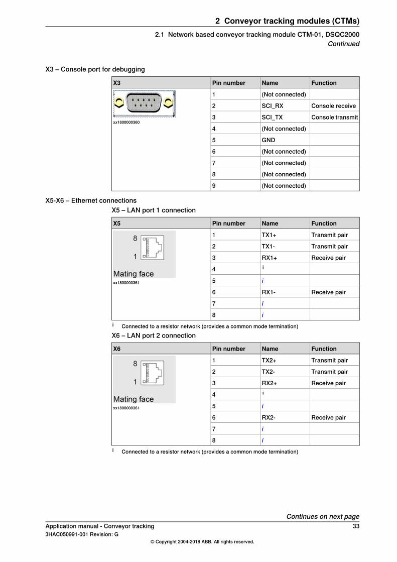
X3 – Console port for debugging
FunctionNamePin numberX3
(Not connected)1
xx1800000360
Console receiveSCI_RX2
Console transmitSCI_TX3
(Not connected)4
GND5
(Not connected)6
(Not connected)7
(Not connected)8
(Not connected)9
X5-X6 – Ethernet connectionsX5 – LAN port 1 connection
FunctionNamePin numberX5
Transmit pairTX1+1
xx1800000361
Transmit pairTX1-2
Receive pairRX1+3i4
i5
Receive pairRX1-6
i7
i8i Connected to a resistor network (provides a common mode termination)X6 – LAN port 2 connection
FunctionNamePin numberX6
Transmit pairTX2+1
xx1800000361
Transmit pairTX2-2
Receive pairRX2+3i4
i5
Receive pairRX2-6
i7
i8i Connected to a resistor network (provides a common mode termination)
Continues on next pageApplication manual - Conveyor tracking 333HAC050991-001 Revision: G
© Copyright 2004-2018 ABB. All rights reserved.
2 Conveyor tracking modules (CTMs)2.1 Network based conveyor tracking module CTM-01, DSQC2000
Continued

X7 – WAN port connection
FunctionNamePin numberX7
Transmit pairTX3+1
xx1800000361
Transmit pairTX3-2
Receive pairRX3+3i4
i5
Receive pairRX3-6
i7
i8i Connected to a resistor network (provides a common mode termination)
X20 – Camera power inlet
FunctionNamePin numberX20
Camera powerinlet
CAM_GND1
xx1800000363
CAM_PWR2
X21-X28 – Camera connections
FunctionNamePin numberX21
Camera 1 poweroutput
CAMPWR11
xx1800000364
CAMPWRGND2
Sync 1 input sig-nal
SYNC13
Power output forsync signal
SYNCPWR14
GND for triggerand sync power
GND5
Trigger 1 outputTRIG16
FunctionNamePin numberX22
Camera 2 poweroutput
CAMPWR21
xx1800000364
CAMPWRGND2
Sync 2 input sig-nal
SYNC23
Power output forsync signal
SYNCPWR24
GND for triggerand sync power
GND5
Trigger 2 outputTRIG26
Continues on next page34 Application manual - Conveyor tracking
3HAC050991-001 Revision: G© Copyright 2004-2018 ABB. All rights reserved.
2 Conveyor tracking modules (CTMs)2.1 Network based conveyor tracking module CTM-01, DSQC2000Continued
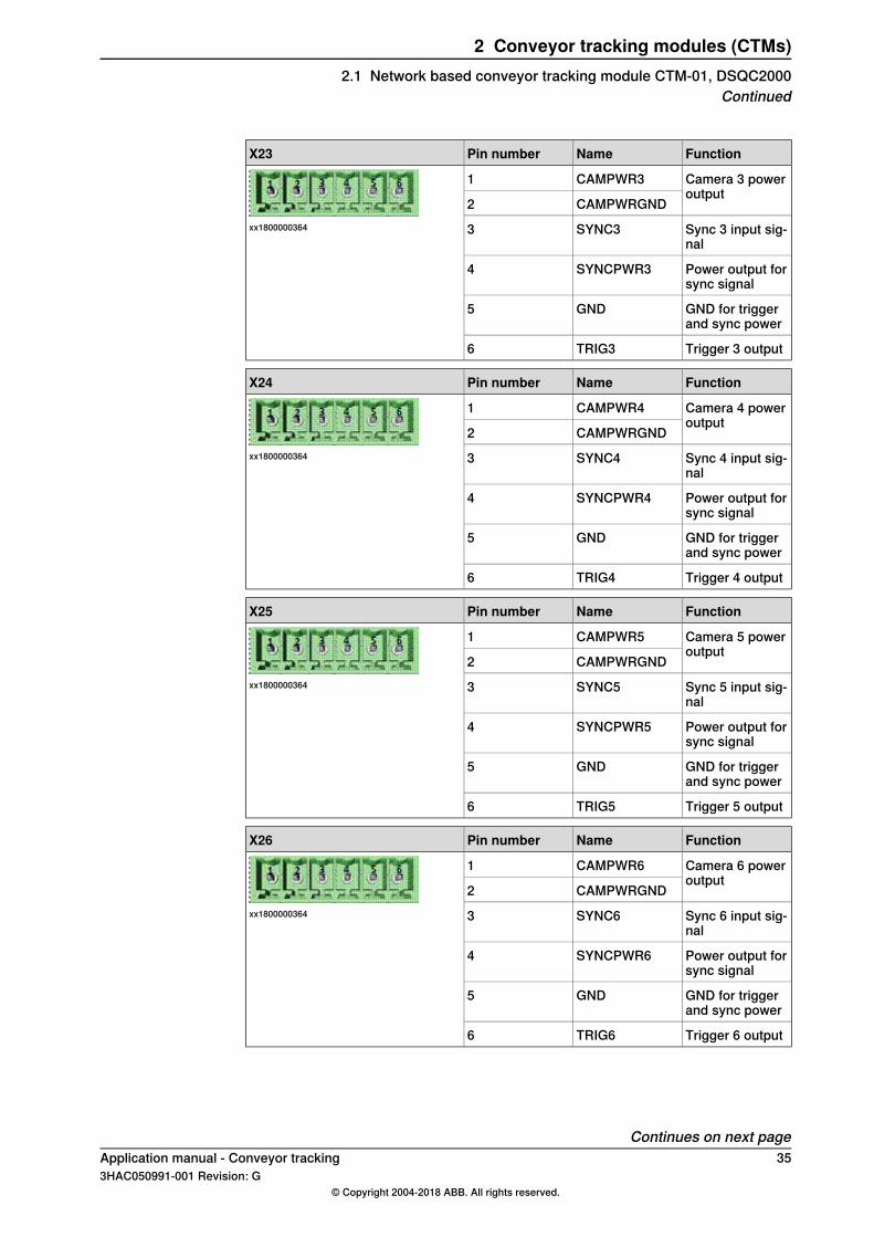
FunctionNamePin numberX23
Camera 3 poweroutput
CAMPWR31
xx1800000364
CAMPWRGND2
Sync 3 input sig-nal
SYNC33
Power output forsync signal
SYNCPWR34
GND for triggerand sync power
GND5
Trigger 3 outputTRIG36
FunctionNamePin numberX24
Camera 4 poweroutput
CAMPWR41
xx1800000364
CAMPWRGND2
Sync 4 input sig-nal
SYNC43
Power output forsync signal
SYNCPWR44
GND for triggerand sync power
GND5
Trigger 4 outputTRIG46
FunctionNamePin numberX25
Camera 5 poweroutput
CAMPWR51
xx1800000364
CAMPWRGND2
Sync 5 input sig-nal
SYNC53
Power output forsync signal
SYNCPWR54
GND for triggerand sync power
GND5
Trigger 5 outputTRIG56
FunctionNamePin numberX26
Camera 6 poweroutput
CAMPWR61
xx1800000364
CAMPWRGND2
Sync 6 input sig-nal
SYNC63
Power output forsync signal
SYNCPWR64
GND for triggerand sync power
GND5
Trigger 6 outputTRIG66
Continues on next pageApplication manual - Conveyor tracking 353HAC050991-001 Revision: G
© Copyright 2004-2018 ABB. All rights reserved.
2 Conveyor tracking modules (CTMs)2.1 Network based conveyor tracking module CTM-01, DSQC2000
Continued

FunctionNamePin numberX27
Camera 7 poweroutput
CAMPWR71
xx1800000364
CAMPWRGND2
Sync 7 input sig-nal
SYNC73
Power output forsync signal
SYNCPWR74
GND for triggerand sync power
GND5
Trigger 7 outputTRIG76
FunctionNamePin numberX28
Camera 8 poweroutput
CAMPWR81
xx1800000364
CAMPWRGND2
Sync 8 input sig-nal
SYNC83
Power output forsync signal
SYNCPWR84
GND for triggerand sync power
GND5
Trigger 8 outputTRIG86
36 Application manual - Conveyor tracking3HAC050991-001 Revision: G
© Copyright 2004-2018 ABB. All rights reserved.
2 Conveyor tracking modules (CTMs)2.1 Network based conveyor tracking module CTM-01, DSQC2000Continued
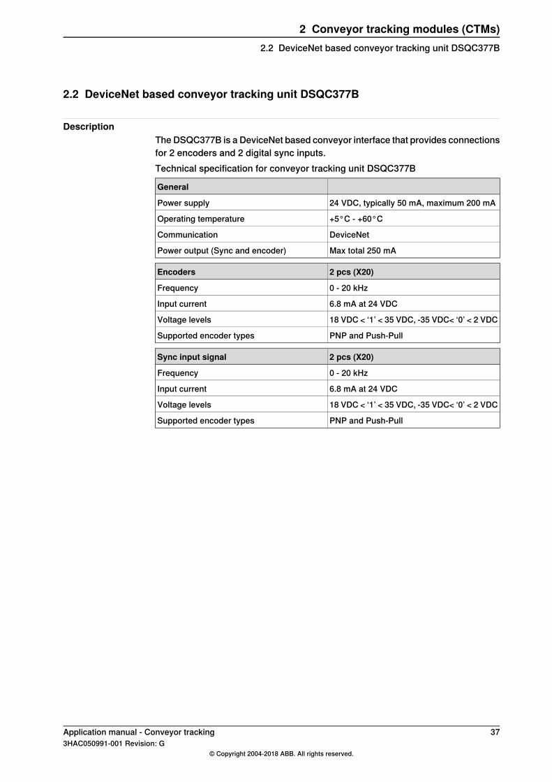
2.2 DeviceNet based conveyor tracking unit DSQC377B
DescriptionThe DSQC377B is a DeviceNet based conveyor interface that provides connectionsfor 2 encoders and 2 digital sync inputs.Technical specification for conveyor tracking unit DSQC377B
General
24 VDC, typically 50 mA, maximum 200 mAPower supply
+5°C - +60°COperating temperature
DeviceNetCommunication
Max total 250 mAPower output (Sync and encoder)
2 pcs (X20)Encoders
0 - 20 kHzFrequency
6.8 mA at 24 VDCInput current
18 VDC < ‘1’ < 35 VDC, -35 VDC< ‘0’ < 2 VDCVoltage levels
PNP and Push-PullSupported encoder types
2 pcs (X20)Sync input signal
0 - 20 kHzFrequency
6.8 mA at 24 VDCInput current
18 VDC < ‘1’ < 35 VDC, -35 VDC< ‘0’ < 2 VDCVoltage levels
PNP and Push-PullSupported encoder types
Application manual - Conveyor tracking 373HAC050991-001 Revision: G
© Copyright 2004-2018 ABB. All rights reserved.
2 Conveyor tracking modules (CTMs)2.2 DeviceNet based conveyor tracking unit DSQC377B

This page is intentionally left blank

3 Installation3.1 Hardware connections
Introduction to hardware installationFor the option Conveyor Tracking or PickMaster 3, the conveyor is connected tothe IRC5 controller using an encoder and either the encoder interface unit(DSQC377B) or the conveyor tracking module (CTM-01, DSQC2000). See Installingthe encoder for conveyor tracking on page 40.For the option Indexing Conveyor Control, the conveyor is controlled by a motorunit (ABB or other). See Installing the additional axis for servo control on page162.
Related informationIf the conveyor is used with IRC5P (for paint applications), see Productmanual - Control cabinet IRC5P.
Application manual - Conveyor tracking 393HAC050991-001 Revision: G
© Copyright 2004-2018 ABB. All rights reserved.
3 Installation3.1 Hardware connections

3.2 Installing the encoder for conveyor tracking
Selecting encoder typeThe encoder provides a series of pulses indicating the motion of the conveyor.This is used to synchronize the motions of the robot to the motion of the conveyor.The encoder has two pulse channels, A and B, that differ in phase by 90°. Eachchannel will send a fixed number of pulses per revolution depending on theconstruction of the encoder.The number of pulses per revolution for the encoder must be selected in relationto the gearing between the conveyor and the encoder. The pulse ratio from theencoder should be in the range of 1250 -2000 pulses per meter of conveyor motion.The pulses from channels A and B are used in quadrature to multiply the pulseratio by 4 to get counts. This means that the control software will measure 5000to 10000 counts per meter for an encoder with the pulse ratio given above. Reducingthe number of measured counts below 5000 will reduce the accuracy of the robottracking. Increasing the number of measured counts above 10000 will have nosignificant effect as inaccuracies in robot and cell calibration will be the dominatingfactors for accuracy.The encoder must be of 2 phase type for quadrature pulses, to register reverseconveyor motion, and to avoid false counts due to vibration etc. when the conveyoris not moving.
Typical spec, Open collector PNP output encoderOutput signal
10 - 30 VVoltage(normally supplied by 24 VDC from DSQC2000, CTM-01)
50 - 100 mACurrent
2 phase with 90 degree phase shiftPhase
50%Duty cycle
An example encoder is the Lenord & Bauer GEL 262.
Technical specification for encoder interface
DSQC377B
24 VDC, typically 50 mA, maximum 200 mAPower supply
+5°C - +60°COperating temperature
0 - 20 kHzEncoder frequency
6.8 mA at 24 VDCEncoder input current
6.8 mA at 24 VDCDigital input current
18 VDC < ‘1’ < 35 VDC-35 VDC< ‘0’ < 2 VDC
Continues on next page40 Application manual - Conveyor tracking
3HAC050991-001 Revision: G© Copyright 2004-2018 ABB. All rights reserved.
3 Installation3.2 Installing the encoder for conveyor tracking
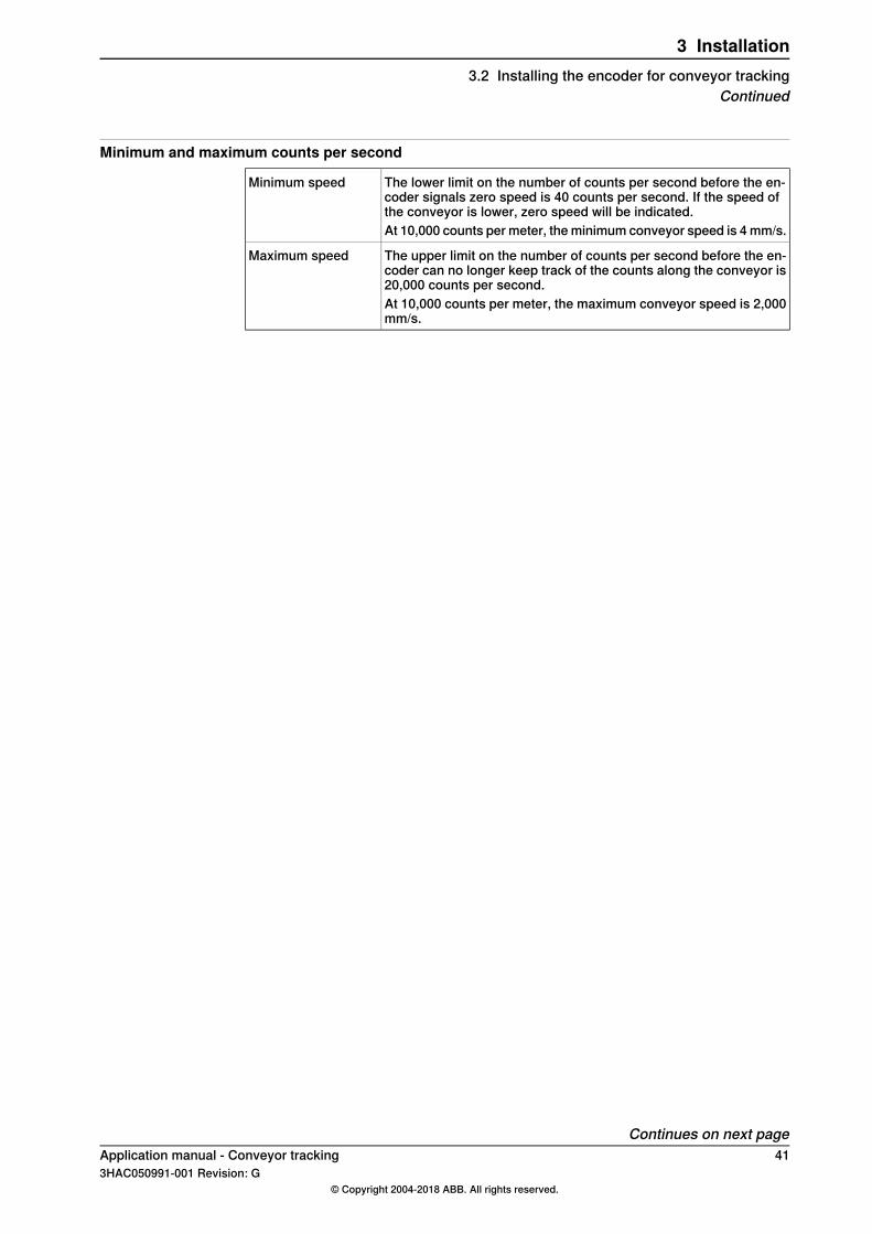
Minimum and maximum counts per second
The lower limit on the number of counts per second before the en-coder signals zero speed is 40 counts per second. If the speed ofthe conveyor is lower, zero speed will be indicated.
Minimum speed
At 10,000 counts per meter, the minimum conveyor speed is 4 mm/s.
The upper limit on the number of counts per second before the en-coder can no longer keep track of the counts along the conveyor is20,000 counts per second.
Maximum speed
At 10,000 counts per meter, the maximum conveyor speed is 2,000mm/s.
Continues on next pageApplication manual - Conveyor tracking 413HAC050991-001 Revision: G
© Copyright 2004-2018 ABB. All rights reserved.
3 Installation3.2 Installing the encoder for conveyor tracking
Continued
3.2.1 Encoder location
DescriptionThe encoder is normally installed on the conveyor drive unit. The encoder can beconnected to an output shaft on the drive unit, directly or via a gear beltarrangement.
PrerequisitesIf the encoder is connected directly to a drive unit shaft, a flexible coupling mustbe used to prevent applying mechanical forces to the encoder rotor. Do not use acoupling using a plastic or rubber hose. If the drive unit includes a clutcharrangement, the encoder must be connected on the conveyor side of the clutch.If the conveyor drive unit is located a long distance away from the robot then theconveyor itself can be a source of inaccuracy as the conveyor will stretch or flexover the distance from the drive unit to the robot cell. In such a case it may bebetter to mount the encoder closer to the robot cell with a different couplingarrangement.
42 Application manual - Conveyor tracking3HAC050991-001 Revision: G
© Copyright 2004-2018 ABB. All rights reserved.
3 Installation3.2.1 Encoder location

3.2.2 Encoder cables
DescriptionThe encoder should be connected to the robot by a screened cable to reduce noise.The noise immunity will be better with screened twisted pair cable. Cable length,pulse frequency and environmental conditions must be taken in account, case bycase.The cable screen can by grounded in one of the following ways:
• Grounded in the controller end, open in the encoder end.• Grounded in both ends.• High frequency connection with a capacitor between screen and ground in
the encoder end.The method for screen connection depends on the environment and can be differentfrom case to case. Parameter like cable length, encoder frequency and otherequipment with power electronics (motor-drive) and so on influence on theelectromagnetic environment.
PWR
GND
A+
A-
B+
B-
GND GND
xx1800001539
PowerPWR
GroundGND
Encoder signal AA+, A-
Encoder signal BB+, B-
Application manual - Conveyor tracking 433HAC050991-001 Revision: G
© Copyright 2004-2018 ABB. All rights reserved.
3 Installation3.2.2 Encoder cables
3.3 Connecting the encoder to the CTM-01, DSQC2000
DescriptionAn encoder is connected to a single encoder interface in the CTM. If multiple robotsare following the same conveyor, its speed and position are supplied by the CTMto all the robot controllers through a network communication.The conveyor tracking module CTM-01, DSQC2000 can be located either insidethe robot controller or a cabinet close to the conveyor encoder (to reduce the cablelength between the CTM and the encoder).
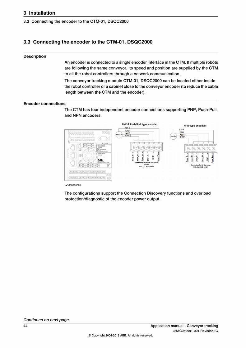
Encoder connectionsThe CTM has four independent encoder connections supporting PNP, Push-Pull,and NPN encoders.
xx1800000365
The configurations support the Connection Discovery functions and overloadprotection/diagnostic of the encoder power output.
Continues on next page44 Application manual - Conveyor tracking
3HAC050991-001 Revision: G© Copyright 2004-2018 ABB. All rights reserved.
3 Installation3.3 Connecting the encoder to the CTM-01, DSQC2000

If the encoder is externally powered, then the CTM power pins must not beconnected. This configuration removes the connection discovery and overloadprotection and diagnostic functions of the encoder power output.
xx1800000366
Connecting to multiple encoder modulesAn encoder requires additional power supply, when connecting to several encoderinterfaces. This extra power supply can be acquired by an external power sourceor from the connected encoder interfaces by using a diode on the power outputsto prevent parallel wiring of the power supplies.
xx1800000367
These configurations do not support overload protection and also do not providethe functions connection discovery and overload diagnostic of the encoder power.
Continues on next pageApplication manual - Conveyor tracking 453HAC050991-001 Revision: G
© Copyright 2004-2018 ABB. All rights reserved.
3 Installation3.3 Connecting the encoder to the CTM-01, DSQC2000
Continued

Connecting the CTM to the robot controllerThe CTM must be powered by a 24 V power supply and connected to Ethernet.There are three main installation methods for the Ethernet communication. Thepower supply connection and Ethernet connection may vary between the differentrobot controllers, see the Robot Controller Product manuals - IRC5.
Mounted in Robot Controller, Sharing conveyor info with other controllersWhen the CTM module is connected to the same network as the robot controllers,the conveyor information may be shared from the CTM module to all the robotcontrollers.
xx1800000368
Note
LAN 3 can also be used on the MC, it is the default for internally mounted CTM.
Mounted outside Robot Controller, Sharing conveyor info with other controllersThe CTM module can be mounted externally, that is outside the robot controller.
xx1800000369
Note
LAN 3 can also be used on the MC, it is the default for internally mounted CTM.
Continues on next page46 Application manual - Conveyor tracking
3HAC050991-001 Revision: G© Copyright 2004-2018 ABB. All rights reserved.
3 Installation3.3 Connecting the encoder to the CTM-01, DSQC2000Continued

Mounted inside Robot Controller, No sharing of conveyor infoIf the conveyor is not shared with any other robot controller, the CTM may beinstalled inside the controller using the LAN network. This will reduce the numberof external WAN ports required on the robot controller.
xx1800000370
Note
The WAN port is used on the CTM and LAN 2 or LAN 3 is used on the MC.
Application manual - Conveyor tracking 473HAC050991-001 Revision: G
© Copyright 2004-2018 ABB. All rights reserved.
3 Installation3.3 Connecting the encoder to the CTM-01, DSQC2000
Continued
3.4 Connecting the encoder to the DSQC377B
Encoder connectionsA single encoder can be connected to one or more DSQC377B units. TheDSQC377B units can be connected to the same robot controller or to differentrobot controllers. Similarly, two DSQC377B units can be connected to the sameor different robot controllers. For example, when two different robots follow thesame conveyor.
Connecting to several controllersAn encoder that is connected to more than one robot controller, can be poweredthrough the robot controllers or from an external power supply.When the encoder is powered from several robot controllers, a diode must beinstalled in each of the 24 VDC connections. This is to prevent parallel wiring ofthe power supplies.
Continues on next page48 Application manual - Conveyor tracking
3HAC050991-001 Revision: G© Copyright 2004-2018 ABB. All rights reserved.
3 Installation3.4 Connecting the encoder to the DSQC377B

Example connection for PNP encoderThe below diagram shows a common encoder for two robots.
A
C0V 24VDC
X20
2
1
4
3
6
5
8
7
10
9
12
11
14
13
16
15
D
D
D
D
D
D
G
H
DI1
DI2
B
0V (9
0°)
A (
0°)
24
VD
C
+24 VDC
0 Volt F
0V 24VDCC
2
1
4
3
6
5
8
7
10
9
12
11
14
13
16
15
X20
D
D
D
D
D
D
G
H
DI1
DI2
E
B
xx1200001078
Robot 1A
Robot 2B
Continues on next pageApplication manual - Conveyor tracking 493HAC050991-001 Revision: G
© Copyright 2004-2018 ABB. All rights reserved.
3 Installation3.4 Connecting the encoder to the DSQC377B
Continued

DSQC354, DSQC377, DSQC377A,DSQC377B.
Encoder interface or queue tracking unit(with galvanic insulation)
C
The units support only PNP and 'push-pull' (E2) encoders.
OptoD
EncoderE
Do not connect internal supply if extern-al is used.
External powerF
Encoder 1G
Used for backup encoder only.Encoder 2H
Digital input 1DI1
Used for backup encoder only.Digital input 2DI2
Connecting the DSQC377B to the robot controllerSee Product manual - IRC5, for details on connecting the DSQC377B to the robotcontroller. See also Application manual - DeviceNet Master/Slave.
50 Application manual - Conveyor tracking3HAC050991-001 Revision: G
© Copyright 2004-2018 ABB. All rights reserved.
3 Installation3.4 Connecting the encoder to the DSQC377BContinued

3.5 Connecting a camera to the CTM-01, DSQC2000
DescriptionThe CTM-01 contains 8 camera connections to connect cameras or sync signals.The cameras can be powered separately or through the CTM.The sync signal input supports PNP and Push-Pull type sensors and can bepowered by the Sync_Pwr output or externally. The trigger output is a 24 V digitaloutput signal.The configuration shown in the following figure, supports overload protection onCameraPower, Sync_Power, and Trig_output. The Connection Discovery functionand the overload protection/diagnostics exist on Sync_Power and Trig_output.
xx1800000371
The configuration shown in the following figure, does not supports overloadprotection on CameraPower. The Connection Discovery function and the overloadprotection/diagnostics exist on Sync_Power and Trig_output.
xx1800000372
Application manual - Conveyor tracking 513HAC050991-001 Revision: G
© Copyright 2004-2018 ABB. All rights reserved.
3 Installation3.5 Connecting a camera to the CTM-01, DSQC2000

3.6 Connecting the sync switches to the CTM-01, DSQC2000
DescriptionThe sync input signal in each of the camera connectors can also be used as a syncswitch. It can be powered by Sync_Pwr output or externally and supports PNP andPush-Pull type sensors, as shown in the following figure:
xx1800000375
52 Application manual - Conveyor tracking3HAC050991-001 Revision: G
© Copyright 2004-2018 ABB. All rights reserved.
3 Installation3.6 Connecting the sync switches to the CTM-01, DSQC2000
4 Conveyor Tracking tab in RobotStudioIntroduction
The Conveyor Tracking tab contains a tree view browser displaying the connectedDSQC2000 units and other related objects. It is used as a user interface to configuresettings and monitor live signals of the DSQC2000 tracking units.
Note
While in the tree view browser or any of the related object dialogues, pressingF1 will open the Application manual - Conveyor tracking.
To open the Conveyor Tracking tab:
Action
Click Conveyor Tracking from the Configuration group, in the Controller tab.The Conveyor Tracking tab opens.
1
Connecting and adding a CTM
Connecting a CTMOne of the following methods can be used to connect the CTM to the computer:
1 Connecting the CTM through a WAN portThis method is recommended only after a fixed IP address is configured forthe CTM - WAN interface, see Network settings on page 54.Connect the computer with a fixed IP address to the same WAN network,through a network switch or a direct connection. Configure the computer’sIP address with the CTM’s subnet.Example:
192.168.8.xxCTM - WAN interface
192.168.8.246Computer network interface
The default factory setting for WAN is Obtain an IP address automatically(DHCP client). To connect a WAN with this setting a DHCP server is requiredon the network.
2 Connecting through a LAN portThis method is recommended for the initial setup of a CTM with default factorysettings. It can also be used for debugging, when there is a connectionproblem with the CTM.Configure the fixed IP address of the computer with the subnet of the CTM– LAN interface. The LAN interface has IP address 192.168.126.200.Example:
192.168.126.200CTM - LAN interface
192.168.126.246Computer network interface
Continues on next pageApplication manual - Conveyor tracking 533HAC050991-001 Revision: G
© Copyright 2004-2018 ABB. All rights reserved.
4 Conveyor Tracking tab in RobotStudio

Adding a CTMTo add a CTM, a connection must be established between the computer and theCTM:
Action
Click Add CTM.The Add CTM dialog box opens.
1
This dialog box displays all the detected CTMs.
Select the CTM from the list and click OK.The CTM is added to the tree view object browser.
2
Identifying a CTM in RobotStudioIf RobotStudio is connected to a network with multiple CTMs, it may become difficultto identify a particular CTM. This can be avoided by a direct connection via LANport, for more information, see Connecting a CTM on page53, section Connectingthrough a LAN port.To simplify identification, it is recommended to assign a unique and descriptivename for every CTM, for more information, see Rename on page 56.One of the following methods can also be used to identify a CTM:
• Select the device in the tree view browser, its corresponding green discoveryLED will start blinking on the CTM module.
• Press the white SW1 button on the CTM module once, a green dot will startblinking on the corresponding CTM symbol in the tree view browser.
WARNING
Do not press the SW1 button while the CTM is restarting, this will reset theCTM to default factory settings and any updates or upgrades will be lost.
Network settingsThe WAN port of the CTM is connected to the robot controllers through an Ethernetnetwork. To establish communication between the robot controllers and the CTM,a fixed IP address must be assigned to the CTM. The IP address should be locatedon the same subnet as the network interface of the connected robot controllers.To change the network settings:
Action
Right-click the CTM in the tree view browser, select Network settings, and thenclick WAN interface.
1
Enter the IP address, the Subnet mask, and the Default gateway (optional) andthen click OK.
2
Continues on next page54 Application manual - Conveyor tracking
3HAC050991-001 Revision: G© Copyright 2004-2018 ABB. All rights reserved.
4 Conveyor Tracking tab in RobotStudioContinued

AuthenticateA CTM has the following two predefined users:
DescriptionDefault pass-word
User
It is an advanced user and is used for advancedmaintenance and troubleshooting.
abbadminabbadmin
It is a normal user and is used for everyday mainten-ance and troubleshooting.
ctmuserctmuser
Note
Login as an advanced user to upgrade the firmware.
To use some features of a CTM, a login is required. If you are using the defaultcredentials, login is automatic to the Conveyor Tracking tab. Otherwise,authentication is requested whenever required.
Note
It is recommended to change the password to improve security.Appropriate credentials are required to make any modifications to the CTMconfiguration and firmware.
WARNING
You cannot recover a lost password, so ensure the password is not lost orforgotten.
To login as a user:
Action
Right-click the CTM and click Authenticate > Login as a Different User.1
Enter the required credentials and click Login.2
To log off the current user:
Action
Right-click the CTM and click Authenticate > Log Off.1
To change the password of the current user:
Action
Right-click the CTM and click Authenticate > Change password.1
Change the password and click OK.2
Continues on next pageApplication manual - Conveyor tracking 553HAC050991-001 Revision: G
© Copyright 2004-2018 ABB. All rights reserved.
4 Conveyor Tracking tab in RobotStudioContinued

RenameYou can rename the CTM, the encoders, and the sensors.To rename any object:
Action
Right-click the object in the tree view browser and then click Rename.The Rename dialog box opens.
1
Enter a new name for the object and then click OK.The new names are stored in the CTM and will be displayed in RobotStudio, onceit is restarted.
2
Configuring an encoderYou can configure some settings of an encoder, for example, Speed filter.To configure an encoder:
Action
Right-click the encoder in the tree view browser and then clickConfigure encoder.The Configure encoder tab opens.
1
Modify the settings and click Apply.2
An encoder can be configured as used or not used. This change in configurationwill affect how the encoder is displayed in the tree view browser. To tune theencoder speed filtering, you can define the Low-pass filter cut off frequency inthe Speed filter section.
Configuring a sensorYou can configure some settings of a sensor, for example, Sync Separation.To configure a sensor:
Action
Right-click the sensor in the tree view browser and then click Configure sensor.The Configure sensor dialog box opens.
1
Modify the settings and click Apply.2
Sync separation is used to filter an unstable signal in the sync input signal. Itdefines the minimum encoder distance (counts) between two sync pulses from thesensor. When the actual distance is shorter than this value, then the second syncpulse is ignored.The sensor type can be configured as I/O Sensor, Camera, or Not used. Thischange in configuration will affect how the sensor is displayed in the tree viewbrowser.
Note
It is recommended to set the same sync separation value for all the encoders.
Continues on next page56 Application manual - Conveyor tracking
3HAC050991-001 Revision: G© Copyright 2004-2018 ABB. All rights reserved.
4 Conveyor Tracking tab in RobotStudioContinued

The camera pulse width defines the pulse length (ms) used with the camera triggersignal.
Note
For high speed conveyors, the pulse length must be shorter than the time betweenconsecutive camera images, so that:Camera pulse width < (Trigger distance in mm / Max conveyor speed in mm/s)/ 1000
Restart
OverviewA restart or reboot of a CTM can be performed using the tree view browser.
RestartA restart is required after modifying the settings of the CTM.To restart the CTM:
Action
Right-click the desired CTM in the tree view browser and then click Restart.1
RebootA reboot is slower than a restart, it corresponds to the restart after cycling thepower.To reboot the CTM:
Action
Right-click the desired CTM in the tree view browser and then click Reboot.1
SignalsThere are 3 types of live signals: encoder, sensor, and other. You can sort andfilter the signals by various properties:
DescriptionSignal property
Name of the signalName
Signal value type, for example, floatType
Signal live valueValue
Signal value unit, for example, HzUnit
Signal category, for example, Public or InternalCategory
Sensor number (1 – 8)Sensor
Encoder number (1 – 4)Encoder
Signal name used in the IRC5 robot controller, for example,TrigVis
Function
Connector on the CTM, for example, X11Label
Information on what the signal representsDescription
Continues on next pageApplication manual - Conveyor tracking 573HAC050991-001 Revision: G
© Copyright 2004-2018 ABB. All rights reserved.
4 Conveyor Tracking tab in RobotStudioContinued

List all signalsTo list all the signals:
Action
Right-click the desired CTM in the tree view browser and then click Signals.1
List all encoder signalsTo list all the encoder signals:
Action
Right-click the desired encoder in the tree view browser and then click Signals.1
List all sensor signalsTo list all the sensor signals:
Action
Right-click the desired sensor in the tree view browser and then click Signals.1
Backup and RestoreYou can save a backup of the CTM settings. The backup will contain:
• Data about the CTM configurations, including encoder and sensor parametersand new names. While restoring the backup, these settings are applied tothe target CTM.
• Network settings• Firmware version information
Creating a backup of the CTMKeeping a backup is recommended to simplify the task of replacing the CTM witha new unit.To create a backup of the CTM:
Action
Right-click the CTM in the tree view browser and then select Create Backup… .The Create Backup from CTM dialog box opens.
1
Enter a Backup Name.2
Enter or select a save Location and click OK.A backup of the CTM is created in the entered location.
3
Restoring a backupTo restore a backup of the CTM:
Action
Right-click the CTM in the tree view browser and then select Restore Backup….The Restore from Backup to CTM dialog box opens.
1
Enter or browse to the required Location, select backup folder and click Open.The backup of the CTM saved in the folder is displayed in the list of the Availablebackups section.
2
Select the required backup from the list and click OK.The CTM’s settings will be restored according to the backup, after a restart of theCTM.
3
Continues on next page58 Application manual - Conveyor tracking
3HAC050991-001 Revision: G© Copyright 2004-2018 ABB. All rights reserved.
4 Conveyor Tracking tab in RobotStudioContinued
Firmware upgradeA firmware upgrade is normally provided by ABB, as a .cab file.
WARNING
It is recommended to backup the CTM configurations, as a firmware upgrademay result in the factory default network settings.
To upgrade the firmware of the CTM:
Action
Login as an advanced user to upgrade the firmware, see Authenticate on page55.1
Right-click the CTM and then click Firmware Upgrade.The Firmware Upgrade dialog box opens.It displays the current version of the firmware.
2
Click Browse, navigate to the .cab file and then click Open.The Verify Software dialog box opens.It displays the publisher of the file.
3
If the publisher is trusted, click Yes.The Firmware Upgrade dialog box opens.It displays the new firmware version.
4
Verify it and click Upgrade, to download it.The CTM will restart after the download and installation.
5
After a firmware upgrade, you may have to restore the network settings of the CTM.Restore a backup (see Restoring a backup on page 58) or manually enter thecorrect network settings.
Application manual - Conveyor tracking 593HAC050991-001 Revision: G
© Copyright 2004-2018 ABB. All rights reserved.
4 Conveyor Tracking tab in RobotStudioContinued

This page is intentionally left blank

5 Configuration and calibration5.1 About software installation and configuration
IntroductionThis section describes how to configure and calibrate the conveyor work area andencoder (if used) with respect to the robot and the robot world frame.The encoder descriptions in this chapter are not valid for the option 606-2 IndexingConveyor Control.If the conveyor is used with IRC5P (painting), see Installation manual - IRC5P RW6.0.DSQC2000 is used as an encoder interface, if the option 1552-1 Tracking UnitInterface is available, if not DSQC377 is used.
Installed software on deliveryThe conveyor tracking functions and the RAPID instructions are specified in thelicense. The conveyor software is already installed on delivery.The Conveyor Tracking option installs one conveyor work area to the IRC5configuration (that is, in the system parameters). To add more conveyor work areas,see Installing additional conveyor work areas for conveyor tracking on page 84.The PickMaster 3 option has a Conveyor Configuration suboption, that can be usedto specify how many conveyor work areas should be installed (0 – 6).
Application manual - Conveyor tracking 613HAC050991-001 Revision: G
© Copyright 2004-2018 ABB. All rights reserved.
5 Configuration and calibration5.1 About software installation and configuration

5.2 Configuration of tracking unit DSQC2000
IntroductionThe Tracking Unit DSQC2000 provides an interface to monitor up to 4 encodersand 8 sensors. One unit can be used simultaneously by up to 40 robot controllers.To be able to use DSQC2000, the robot controller needs the software option 1552-1Tracking Unit Interface.
Cyber security for installations with DSQC2000For information on addressing security threats in a network installation withDSQC2000 and ABB IRC5 systems, see Operating manual - IRC5 Integrator'sguide, section Cyber security for IRC5 robot networks.
Connecting a robot controller to the tracking unit DSQC2000The robot controller is connected to the DSQC2000 Tracking Unit through anEthernet network.DSQC2000 has 3 network interfaces: WAN and 2 LAN. The WAN interface is usedto communicate with robot controllers.If the DSQC2000 is shared by more than one robot controller, it should be connectedto the LAN 3 or WAN port of the robot main computers. When used with a singlerobot controller, additionally it is possible to connect a DSQC2000 on the privatenetwork, for example, LAN 2 of the robot main computer.
xx1800000382
Note
To establish a communication between the robot controller and the CTM, the IPaddress of the robot controller must be on the same subnet as the CTM.
Continues on next page62 Application manual - Conveyor tracking
3HAC050991-001 Revision: G© Copyright 2004-2018 ABB. All rights reserved.
5 Configuration and calibration5.2 Configuration of tracking unit DSQC2000

To setup and verify a communication between the DSQC2000 and the robotcontroller:
Action
Configure the IP address of the CTM, see Network settings on page 54.1
Configure a RobICI device. For example, CTM1, in the robot controller, see Con-figuring a DSQC2000 in the robot controller on page 67.
2
Configure the IP address of the RobICI device, using the IP address of the CTM.3
Configure the IP address of the selected robot controller network interface (LAN2, LAN 3, or WAN), see Examples on page 63.
4
Restart the robot controller.5
Check the state of the I/O devices. The communication is established, if the CTM1is in Running state.
6
ExamplesExample 1If the CTM is connected to the robot controller - WAN interface (Public Network):
192.168.8.48CTM WAN interface
192.168.8.48Robot controller, RobICI device IP address
192.168.8.50Robot controller WAN interface
To view or change the IP address of the robot controller on the WAN interface, editsystem parameters in RobotStudio. See Technical reference manual - Systemparameters, section Type IP Setting.Example 2If the CTM is connected to the robot controller - LAN 3 interface:
192.168.7.48CTM WAN interface
192.168.7.48Robot controller, RobICI device IP address
192.168.7.50Robot controller LAN 3 interface
To configure the IP address of the robot controller on the LAN 3 interface, editsystem parameters in RobotStudio. See Technical reference manual - Systemparameters, section Type IP Setting. If an instance of LAN 3 already exists, modifyit or create a new instance of it.Example 3If the CTM is connected to the robot controller - LAN 2 interface (Private Network):
192.168.125.20CTM WAN interface
192.168.125.20Robot controller, RobICI device IP address
192.168.125.1Robot controller LAN 2 interface
To view or change the IP address of the robot controller on the Private Network,edit system parameters in RobotStudio. See Technical reference manual - Systemparameters, section Type IP Setting.
Continues on next pageApplication manual - Conveyor tracking 633HAC050991-001 Revision: G
© Copyright 2004-2018 ABB. All rights reserved.
5 Configuration and calibration5.2 Configuration of tracking unit DSQC2000
Continued
Configuring a DSQC2000 with RobotStudioThe DSQC2000 unit is configured using RobotStudio. You can connect a computerwith RobotStudio to the WAN or LAN port of the DSQC2000.In the Controller tab click on Conveyor Tracking from the Confiuration group. AConveyor Tracking tab is displayed.You can search for any conveyor tracking units on the network, see Connectingand adding a CTM on page 53.
Minimum configurationThe setup of The IP address of the WAN interface is the minimum configurationrequired, see Network settings on page 54. A communication between the CTMand a robot controller can be established only after the IP address is defined.You can change the following parameters:
• Name of the CTM and name of individual encoders and sensors, seeRenameon page 56.
• Encoder parameters, see Configuring an encoder on page 56.• Sensor parameters, see Configuring a sensor on page 56.
Configuring a DSQC2000To configure a DSQC2000 with RobotStudio:
Action
In the Controller tab, click Conveyor Tracking from the Confiuration group.For more information on conveyor tracking units on the network, see Connectingand adding a CTM on page 53.
1
64 Application manual - Conveyor tracking3HAC050991-001 Revision: G
© Copyright 2004-2018 ABB. All rights reserved.
5 Configuration and calibration5.2 Configuration of tracking unit DSQC2000Continued

5.3 Verifying the installation of encoders and sensors (DSQC2000 only)
DescriptionDSQC2000 provides functionality that simplifies the verifications of installedencoders and sensors. These verifications can be done by connecting RobotStudioto the CTM. The verifications are based on the monitoring of certain CTM signalsand are independent of robot controllers.
Verifying if the encoder is electrically connected to the powerThis test is only applicable if the encoder is powered by the encoder interface.To verify if the encoder is electrically connected to the power:
Action
Open the signals for the encoder, see List all encoder signals on page 58.1
Restart the CTM.2
Verify the value of TwoPhaseEncX:PowerWired.If the value is 1, it indicates that the encoder is connected to the power supply.If the value is 0, it indicates that the encoder is not connected to the power supply.
3
Verifying if the trigger signal is electrically connected to a cameraTo verify if the trigger signal is electrically connected to a camera:
Action
Open the signals for the sensor, see List all sensor signals on page 58.1
Verify if the value of DigoutX:Wired is 1, else check the connection of the triggersignal and the GND with the camera.
2
Verifying the encoder functionTo verify the encoder function:
Action
Open the signals for the encoder, see List all encoder signals on page 58.The encoder function can be checked by monitoring the signal EncX:position thatdisplays the encoder count for encoder X.
1
Move the conveyor and verify if the EncX:position changes accordingly.2
If the value does not change or is unstable, verify if the encoder is properly in-stalled, electrically and mechanically.
3
Verifying the sensor functionTo verify the sensor function:
Action
Open the signals for the sensor, see List all sensor signals on page 58.The sensor function can be checked by monitoring the signal syncXencY:Value,it displays the encoder count for encoder Y at the latest sync input event on sensorX.
1
Move the conveyor Y a short distance.2
Generate a sync input from the sensor, for example by detecting a object with anI/O sensor or by triggering an image with a camera sensor.
3
Continues on next pageApplication manual - Conveyor tracking 653HAC050991-001 Revision: G
© Copyright 2004-2018 ABB. All rights reserved.
5 Configuration and calibration5.3 Verifying the installation of encoders and sensors (DSQC2000 only)

Action
Verify if the syncXencY:Value is same as the value of the EncY:position.4
If the value is not the same, verify if the encoder is properly installed, electricallyand mechanically.
5
Verifying the direction of positive motionTo verify the direction of positive motion:
Action
Open the signals for the encoder, see List all encoder signals on page 58.The EncX:position signal displays the encoder count for encoder X.
1
Move the conveyor towards the robot and verify if the signal value increases ordecreases.The EncX:position signal displays the encoder count for encoder X.
2
If the signal value increases, the direction of positive motion is correct.3If the signal value decreases, reverse the A and B inputs from the encoder to theencoder interface.
Identify the gear ratioOpen the signals for the encoder, see List all encoder signals on page 58.The gear ratio defines the motion distance of the conveyor as a function ofmeasured encoder counts.The gear ratio can be used configure the system parameter CountsPerMeter forthe conveyor work area. It can be identified with the following procedure:
Action
Record the first encoder count C1 as EncX:position.1
Move the conveyor forward for at least1 meter. Measure the actual movementdistance D. For a linear conveyor, D is measured in meter. For a rotational con-veyor, D is measured in radians.
2
Record a second encoder count C2 as EncX:position.3
Calculate the gear ratio = (C2 – C1) / D.4
66 Application manual - Conveyor tracking3HAC050991-001 Revision: G
© Copyright 2004-2018 ABB. All rights reserved.
5 Configuration and calibration5.3 Verifying the installation of encoders and sensors (DSQC2000 only)Continued

5.4 Configuration of robot controllers (DSQC2000 only)
Configuring a DSQC2000 in the robot controllerIn the robot controller configuration, DSQC2000 is represented as a RobICI I/Odevice on the RobICI network. The RobICI network is an internal ABBcommunication protocol, see Operating manual - IRC5 Integrator's guide, sectionCyber security for IRC5 robot networks.The Conveyor Tracking option installs one RobICI device to the RobICI network.The PickMaster 3 option installs one RobICI device if 1 - 6 conveyor work areashave been selected in the suboption Conveyor Configuration.Additional RobICI devices can be added using RobotStudio. There are templatesavailable to setup Conveyor Tracking Device 2, Conveyor Tracking Device 3, andConveyor Tracking Device 4.Following needs to be configured for a RobICI device:
• The configured IP address of the DSQC2000 unit.
Configuring a conveyor work area using DSQC2000For each conveyor work area, a selection needs to be made on which encoder andwhich sensor that shall be used for conveyor tracking.
xx1800000384
Continues on next pageApplication manual - Conveyor tracking 673HAC050991-001 Revision: G
© Copyright 2004-2018 ABB. All rights reserved.
5 Configuration and calibration5.4 Configuration of robot controllers (DSQC2000 only)

The selection is made by modifying the DeviceMap of nine I/O signals that belongsto the conveyor work area. The nine signals are mapped to the configuredDSQC2000 device. The value in the DeviceMap column represent encoder andsensor numbers.In this example, conveyor work area 1 is used with encoder 1 and sensor 1 onCTM1. The DeviceMap is adjusted accordingly:
DeviceMap digitsrepresent
DeviceMapDeviceName
Encoder 1Enc1:positionCTM1c1Counts
Encoder 1Enc1:velocityCTM1c1CountsPerSec
Encoder 1e1_SpeedBand-Width:SetPoint
CTM1c1SpeedBandWidth
Sensor 1Digout1:SetpointCTM1c1TrigVis
Sensor 1Cam1:ConnectCTM1c1TrigAutoMode
Sensor 1Cam1:IntervalCTM1c1TrigAutoDist
Sensor 1Cam1Enc:DeviceNoCTM1c1TrigAutoEncNo
Sensor 1, encoder 1Sync1Enc1:SyncTrigCTM1c1SoftSync
Sensor 1, encoder 1Sync1Enc1:ValueCTM1c1CntFromEnc
In this example, conveyor work area 2 is used with encoder 2 and sensor 8 onCTM1. The DeviceMap is adjusted accordingly:
DeviceMap digitsrepresent
DeviceMapDeviceName
Encoder 2Enc2:positionCTM1c2Counts
Encoder 2Enc2:velocityCTM1c2CountsPerSec
Encoder 2e2_SpeedBand-Width:SetPoint
CTM1c2SpeedBandWidth
Sensor 8Digout8:SetpointCTM1c2TrigVis
Sensor 8Cam8:ConnectCTM1c2TrigAutoMode
Sensor 8Cam8:IntervalCTM1c2TrigAutoDist
Sensor 8Cam8Enc:DeviceNoCTM1c2TrigAutoEncNo
Sensor 8, encoder 2Sync8Enc2:SyncTrigCTM1c2SoftSync
Sensor 8, encoder 2Sync8Enc2:ValueCTM1c2CntFromEnc
In this example, conveyor work area 3 is used with encoder 4 and sensor 5 onCTM1. The DeviceMap is adjusted accordingly:
DeviceMap digitsrepresent
DeviceMapDeviceName
Encoder 4Enc4:positionCTM1c3Counts
Encoder 4Enc4:velocityCTM1c3CountsPerSec
Encoder 4e4_SpeedBand-Width:SetPoint
CTM1c3SpeedBandWidth
Sensor 5Digout5:SetpointCTM1c3TrigVis
Sensor 5Cam5:ConnectCTM1c3TrigAutoMode
Continues on next page68 Application manual - Conveyor tracking
3HAC050991-001 Revision: G© Copyright 2004-2018 ABB. All rights reserved.
5 Configuration and calibration5.4 Configuration of robot controllers (DSQC2000 only)Continued

DeviceMap digitsrepresent
DeviceMapDeviceName
Sensor 5Cam5:IntervalCTM1c3TrigAutoDist
Sensor 5Cam5Enc:DeviceNoCTM1c3TrigAutoEncNo
Sensor 5, encoder 4Sync5Enc4:SyncTrigCTM1c3SoftSync
Sensor 5, encoder 4Sync5Enc4:ValueCTM1c3CntFromEnc
Application manual - Conveyor tracking 693HAC050991-001 Revision: G
© Copyright 2004-2018 ABB. All rights reserved.
5 Configuration and calibration5.4 Configuration of robot controllers (DSQC2000 only)
Continued

5.5 Direction of positive motion from the encoder (DSQC377 only)
DescriptionIf an encoder is used, the encoder direction for positive motion can be checkedafter the correct installation of the conveyor tracking software.Run an object past the synchronization switch while viewing the conveyor positionon the FlexPendant, from the Jogging or the I/O window.If the value is negative, reverse the A and B inputs from the encoder to the encoderinterface.
70 Application manual - Conveyor tracking3HAC050991-001 Revision: G
© Copyright 2004-2018 ABB. All rights reserved.
5 Configuration and calibration5.5 Direction of positive motion from the encoder (DSQC377 only)

5.6 Calibrating CountsPerMeter (DSQC377)
DescriptionIf the exact gear ratio between the encoder and the conveyor is unknown (typicallythe case) then the system parameter CountsPerMeter must be calibrated usingeither a tape-measure or the robot TCP as a measuring device.
Calculating CountsPerMeterThe parameter can be calibrated using either a tape-measure or the robot TCP asa measuring device. If the robot TCP is used as the measuring device then anaccurately defined tool must be used. The DSQC377B will keep track of all objectsthat have passed the synchronization switch but have not yet passed the 0.0 mpoint. It is not possible to connect to these objects. First configure the DSQC377Bfor 10,000 CountsPerMeter (default) and the system parameter QueueTrckDist of0.0 m.
Calibrating CountsPerMeter and QueueTrckDistMove an object past the sync switch and stop the conveyor. Read the conveyorposition from the Jogging window, position_1. Move the conveyor at least 1meter and read position_2. The accuracy will be best if this distance is large aspossible within the work space. Use a tape-measure (or differences in robot toolposition) to find the exact distance between position_1 and position_2. Thisis called measured_meters.Use this formula to calculate CountsPerMeter:
Use this procedure to modify CountsPerMeter and QueueTrckDist on theFlexPendant.
1 On the ABB menu, tapControl panel andConfiguration and then tap Topicsand I/O.
2 Tap the type Fieldbus Command.3 Tap CountsPerMeter and change the value to 10000.4 Tap OK.5 Tap QueueTrckDist and change the value to 0.0.6 Tap OK.7 Measure and calculate the exact value as described below, see Calculating
CountsPerMeter on page 71.8 Change the value of CountsPerMeter again to the calculated value.9 Tap OK.
See Type Fieldbus Command (DSQC377 only) on page 100.
Application manual - Conveyor tracking 713HAC050991-001 Revision: G
© Copyright 2004-2018 ABB. All rights reserved.
5 Configuration and calibration5.6 Calibrating CountsPerMeter (DSQC377)

5.7 Calibrating CountsPerMeter (DSQC2000)
DescriptionIf the exact gear ratio between the encoder and the conveyor is unknown (typicallythe case) then the system parameter CountsPerMeter must be calibrated usingeither a tape-measure or the robot TCP as a measuring device.If the robot TCP is used as the measuring device then an accurately defined toolmust be used.If the gear ratio is identified for the encoder, see Identify the gear ratio on page 66,its value can be used for CountsPerMeter. Alternatively, the method mentioned inthe Calculating and calibrating CountsPerMeter on page 72 section can be used.
Calculating and calibrating CountsPerMeterThe counts from the encoder can be found by reading a predefined I/O signal. Forexample CNV1 the signal name is c1counts. Note the counts for the currentconveyor position (named counts_1 in the formula below) and then move awaythe conveyor at least 1 meter. Read the counts again (named counts_2) andmeasure the distance the conveyor is moved (named measured_meters). Theaccuracy will be best if this distance is large as possible within the work space.Use a tape-measure (or differences in robot tool position) to find the exact distance.Use this formula to calculate CountsPerMeter:
Use this procedure to modify CountsPerMeter on the FlexPendant.1 On the ABB menu, tapControl panel andConfiguration and then tap Topics
and Process.2 Tap the type Conveyor Ici.3 Tap CountsPerMeter and change the value.4 Tap OK.
72 Application manual - Conveyor tracking3HAC050991-001 Revision: G
© Copyright 2004-2018 ABB. All rights reserved.
5 Configuration and calibration5.7 Calibrating CountsPerMeter (DSQC2000)
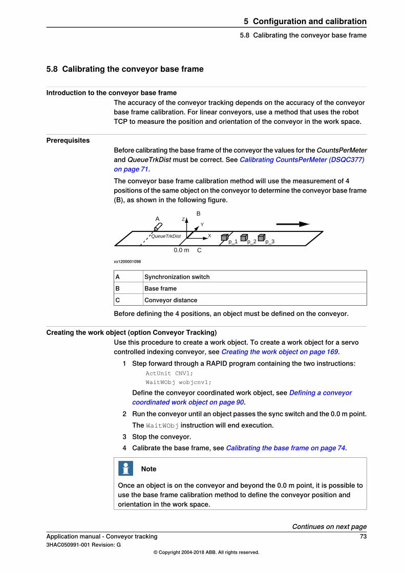
5.8 Calibrating the conveyor base frame
Introduction to the conveyor base frameThe accuracy of the conveyor tracking depends on the accuracy of the conveyorbase frame calibration. For linear conveyors, use a method that uses the robotTCP to measure the position and orientation of the conveyor in the work space.
PrerequisitesBefore calibrating the base frame of the conveyor the values for theCountsPerMeterand QueueTrkDist must be correct. See Calibrating CountsPerMeter (DSQC377)on page 71.The conveyor base frame calibration method will use the measurement of 4positions of the same object on the conveyor to determine the conveyor base frame(B), as shown in the following figure.
A
QueueTrkDist
C0.0 m
BZ
X
Y
p_2 p_3p_1
xx1200001098
Synchronization switchA
Base frameB
Conveyor distanceC
Before defining the 4 positions, an object must be defined on the conveyor.
Creating the work object (option Conveyor Tracking)Use this procedure to create a work object. To create a work object for a servocontrolled indexing conveyor, see Creating the work object on page 169.
1 Step forward through a RAPID program containing the two instructions:ActUnit CNV1;
WaitWObj wobjcnv1;
Define the conveyor coordinated work object, see Defining a conveyorcoordinated work object on page 90.
2 Run the conveyor until an object passes the sync switch and the 0.0 m point.The WaitWObj instruction will end execution.
3 Stop the conveyor.4 Calibrate the base frame, see Calibrating the base frame on page 74.
Note
Once an object is on the conveyor and beyond the 0.0 m point, it is possible touse the base frame calibration method to define the conveyor position andorientation in the work space.
Continues on next pageApplication manual - Conveyor tracking 733HAC050991-001 Revision: G
© Copyright 2004-2018 ABB. All rights reserved.
5 Configuration and calibration5.8 Calibrating the conveyor base frame

Creating the work object (option PickMaster 3)Load and run the RAPID program PrepareCalib.prg. It is located in the HOMEfolder.Select the conveyor work area, CNVX, which needs calibration and let the programexecution complete.
Calibrating the base frameUse this procedure to calibrate the conveyor base frame (applicable for bothConveyor Tracking and Indexing Conveyor Control).If the PickMaster 3 option is used, see Application manual - PickMaster 3, sectionCalibration procedure IRC5.
1 On the FlexPendant, open the Calibration window and select the conveyor.2 Tap Base Frame.3 Tap 4 Point.4 Select the first point, Point 1. This point will be the origin for the user frame
in the conveyor coordinated work object.5 Point out Point 1 on the object on the conveyor with the robot TCP.6 Modify the position by tapping ModPos.7 Move the conveyor in the positive direction and repeat the above for the
points 2, 3, and 4.8 Tap OK to calculate the base frame for the selected conveyor mechanical
unit.A dialog with the calibration result is shown. The calculation log shows theconveyor base frame expressed in the world coordinate system, seeCalculation result for the base frame on page 74.
9 To save the calculation result in a separate file for later use in a PC:a Tap File.b Specify a name and a location where to save the result.c Tap OK.
10 If the estimated error is:• Acceptable, tap OK to confirm the new user frame.• Not acceptable, tap Cancel and redefine.
11 Restart the controller and verify the results of the calibration. See Verifyingthe base frame calibration on page 75.
Calculation result for the base frame
DescriptionField
The name of the mechanical unit for which the definition of baseframe has be done.
Unit
DescriptionList contents
Displays the selected calibration method.Method
The accuracy of the robot positioning against the reference point.Mean error
Continues on next page74 Application manual - Conveyor tracking
3HAC050991-001 Revision: G© Copyright 2004-2018 ABB. All rights reserved.
5 Configuration and calibration5.8 Calibrating the conveyor base frameContinued

DescriptionField
The maximum error for one positioning.Max error
The x coordinate for the base frame.Cartesian X
The y coordinate for the base frame.Cartesian Y
The z coordinate for the base frame.Cartesian Z
Orientation components for the base frame.Quaternion 1-4
Verifying the base frame calibrationIf the PickMaster 3 option is used, see Application manual - PickMaster 3, sectionVerifying the calibrations.After restarting the controller, use this procedure to verify the conveyor base framecalibration.
1 Create a work object, see:• Creating the work object (option Conveyor Tracking) on page 73, for
Conveyor Tracking.• Calibrating the base frame on page169, for Indexing Conveyor Control.
2 Move the robot tool center point back to the previously chosen point 1 onthe work object.
3 In the Jogging window, read the X, Y, Z position of the tool center point.Make sure to use the correct tool and wobjcnv1.
4 The robot TCP x, y, and z position in the work object coordinates should be0.0 mm (or very close to that).
5 In the Jogging window, select the work object wobjcnv1 and coordinatesystem WObj and jog the robot in the x, y, and z directions of the conveyor.Verify that the x-direction is in the direction of positive motion of the conveyor.
Application manual - Conveyor tracking 753HAC050991-001 Revision: G
© Copyright 2004-2018 ABB. All rights reserved.
5 Configuration and calibration5.8 Calibrating the conveyor base frame
Continued

5.9 Defining conveyor start window and sync separation
Start windowThe start window is the length along the conveyor in which objects are trackedand are ready for connection. When a WaitWObj instruction is issued the systemwill connect to the first object inside the start window or wait otherwise.If an object goes beyond the start window then it is no longer tracked and it is notavailable for connection. Such objects are automatically skipped. The purpose ofthe start window is to provide a buffer of objects for speed variations of theconveyor. If an object is connected within the start window then it should be certainthat the motion coordinated to the object can be completed before the workingarea limit or maximum distance is reached.
Sync separationThe parameter Sync Separation is used to filter out unwanted sync signals from asynchronization switch. This parameter establishes a minimum distance that theconveyor must move after one sync signal before a new sync signal is acceptedas a valid object.
Defining start window and sync separation (DSQC2000)Sync separation is configured for each encoder directly on the tracking unit, seeConfiguring a DSQC2000 with RobotStudio on page 64.The start window is configured on the robot controller for the conveyor work areas.Use this procedure to define the start window on the FlexPendant.
1 On the ABB menu, tap Control panel and Configuration and select the topicProcess.
2 Tap type Conveyor Ici.3 Select the parameter StartWinWidth and change value.4 Tap OK.
Defining start window and sync separation (DSQC377B)Use this procedure to define the start window and the sync separation on theFlexPendant.
1 On the ABB menu, tap Control panel and Configuration and select the topicI/O.
2 Tap type Fieldbus Command.3 Select the parametersStartWinWidth andSyncSeparation and change values.4 Tap OK.
See Type Fieldbus Command (DSQC377 only) on page 100.
76 Application manual - Conveyor tracking3HAC050991-001 Revision: G
© Copyright 2004-2018 ABB. All rights reserved.
5 Configuration and calibration5.9 Defining conveyor start window and sync separation

5.10 Avoiding robot reach problems
DescriptionA strategy is required to avoid coordination of motion beyond the reach of therobot.With the Conveyor Tracking option, it is possible to setup maximum and minimumdistances of the conveyor, to simplify this task.With the PickMaster 3 option, coordination of motion beyond the reach of the robotcan be prevented with UseReachableTargets, see UseReachableTargets - Usereachable targets on page 111.
Maximum and minimum distancesIt is possible to monitor the position of the conveyor and automatically drop anyconnected objects that move outside the maximum or minimum specified distance.The purpose is to prevent coordination of motion beyond the work area of the robotfor both forward and backward operation of the conveyor.
Defining maximum and minimum distancesUse this procedure to define the distances on the FlexPendant.
1 On the ABB menu, tap Control panel and Configuration and select the topicProcess.
2 Tap type Conveyor systems.3 Select CNV1.4 Select the parametersmaximum distance andminimum distance and change
the values.5 Tap OK.
If you are using DSQC377, proceed with the following procedure:6 Tap Back and select the type Can interface.7 Select CAN1.8 Select the parameter Supervise max_dist Off and set the value to No.9 Tap OK.
If you are using DSQC2000, proceed with the following procedure:10 Tap Back and select the type Conveyor Ici.11 Select ICI1.12 Select the parameter Supervise max_dist Off and set the value to No.13 Tap OK.
See Topic Process on page 101.
Application manual - Conveyor tracking 773HAC050991-001 Revision: G
© Copyright 2004-2018 ABB. All rights reserved.
5 Configuration and calibration5.10 Avoiding robot reach problems

5.11 Using a trigger output on the DSQC2000
DescriptionThe trigger output signals in the DSQC2000 are primarily intended to control imageacquisition of cameras.A trigger output can be operated in two ways, manual mode or auto mode. Automode is used when a fixed distance is required between consecutive images.Manual mode is used when image acquisition should be controlled by a signal, forexample from a RAPID program.The DO signal, cXTrigAutoMode, is used to switch modes, where the value 1activates auto mode and 0 activates manual mode.
Manual modeIn manual mode, the DO signal, cXTrigVis, can be used to set or reset the triggeroutput, for example from a RAPID program.
Auto modeIn auto mode, the trigger output will be pulsed by the DSQC2000 at a selectedfrequency according to the encoder distance.The supervised encoder (1, 2, 3, or 4) is selected by the GO signal,cXTrigAutoEncNo.The distance interval (number of counts) is selected by the GO signal,cXTrigAutoDist.The pulse length of the signal can be modified by configuring DSQC2000 throughRobotStudio, see Configuring a sensor on page 56.
PickMaster 3 OptionWith the PickMaster 3 option, select cXTrigVis as the trigger signal in the PickMasterapplication, see Application manual - PickMaster 3. Auto mode selection, encoderselection, and distance interval is fully managed by PickMaster. The pulse lengthcan be modified by configuring DSQC2000 through RobotStudio, see Configuringa sensor on page 56.
78 Application manual - Conveyor tracking3HAC050991-001 Revision: G
© Copyright 2004-2018 ABB. All rights reserved.
5 Configuration and calibration5.11 Using a trigger output on the DSQC2000

5.12 Defining the robot adjustment speed
Adjusting the speedWhen entering conveyor tracking, the robot must adjust its speed to the speed ofthe conveyor. The speed with which the robot catches up to the conveyor for thefirst motion is controlled by the parameter adjustment speed.If the conveyor speed is higher than 200 mm/s then this parameter may have tobe increased so the robot can quickly move to the first point on the conveyor. Forexample, set the speed to 130% of the actual conveyor speed.
Defining the robot adjustment speedUse this procedure to define the robot adjustment speed on the FlexPendant.
1 On the ABB menu, tap Control panel and Configuration and select the topicProcess.
2 Tap the type Conveyor systems and select CNV1.3 Select the parameter adjustment speed and change the values.4 Tap OK.
See Type Conveyor systems on page 101.
Application manual - Conveyor tracking 793HAC050991-001 Revision: G
© Copyright 2004-2018 ABB. All rights reserved.
5 Configuration and calibration5.12 Defining the robot adjustment speed
5.13 Additional adjustments
DescriptionThere are more parameters that can be adjusted in the motion system.
Regulating CPU load and accuracyThe parameter Path Resolution specifies the period of the path planner in planningsteps along the path (no units). Step calculations require lots of CPU time and ifsteps cannot be calculated in time to keep the robot on the path then error 50082Deceleration Limit may occur. As conveyor tracking increases the general CPUload then the parameter Path Resolution can be increased if this error occurs. SeeType Motion Planner on page 104.
Defining the mechanical unit parametersThe mechanical unit parameters define the name used in RAPID, and the conditionsfor activation and deactivation.These parameters can be changed to ensure activation of the conveyor. See TypeMechanical Unit on page 104.
Defining additional robot parametersSome parameters in the type Robot (topic Motion) can need adjustments. SeeType Robot on page 104.
80 Application manual - Conveyor tracking3HAC050991-001 Revision: G
© Copyright 2004-2018 ABB. All rights reserved.
5 Configuration and calibration5.13 Additional adjustments

5.14 Configuring a track motion to follow a conveyor
Track following a conveyorIf the robot is mounted on a track, and the track is parallel to the conveyor, thenthe motion can be configured so that the track follows the conveyor. The robot andthe track must be configured for coordinated track motion. See Operatingmanual - IRC5 with FlexPendant for information on configuring coordinated motion.Once the robot and track are configured for coordinated motion, then conveyortracking will automatically use the track to follow the conveyor. The track willmaintain the same position relative to the object as the object moves on theconveyor as it was during programming.The track and robot base frame must be defined so that positive motion of the trackis in the same direction as the conveyor. In some installations this may require are-definition of the track’s direction of positive motion and calibration position.
Example configuration of track and conveyor directionsThe following figure shows an example configuration.
A
IRB
B
- | +
YB
YA
YIRB
XA
XB
XIRB
xx1200001099
ConveyorAThe arrow shows the direction of movement for the conveyor
Track motionBThe -|+ shows the direction of movement for the track
1, 0, 0, 0Conveyor quaternion
0.7071, 0, 0, 0.7071Robot base quaternion
1, 0, 0, 0Track base quaternion
Continues on next pageApplication manual - Conveyor tracking 813HAC050991-001 Revision: G
© Copyright 2004-2018 ABB. All rights reserved.
5 Configuration and calibration5.14 Configuring a track motion to follow a conveyor

Recommendations for programmingAvoid moving the track when programming the conveyor coordinated instructionsin the RAPID program. All motions of the track relative to the conveyor are savedand played back during conveyor tracking. Tracks typically have an accelerationability that is far below that of the robot joints. If the track must move relative tothe object then this will require an acceleration that will cause a reduction of therobot’s TCP speed along the path in order to maintain coordination.
Tracking the conveyor with a robot instead of a trackIf the robot base is not coordinated with the track axis, then the robot will doconveyor tracking without using the track. If the robot base frame is coordinatedwith the track, and conveyor tracking with the robot (instead of the track) is wanted,then change the parameter Track Conveyor With Robot in the type Robot (topicMotion). See Type Robot on page 104.
82 Application manual - Conveyor tracking3HAC050991-001 Revision: G
© Copyright 2004-2018 ABB. All rights reserved.
5 Configuration and calibration5.14 Configuring a track motion to follow a conveyorContinued
5.15 Installing conveyor tracking software
Installing conveyor tracking in an existing system (DSQC377)Use this procedure to install the option Conveyor tracking in an existing system.Three configurations will be added:
• I/O for the DSQC377B• System parameters for the conveyor in the topic Process• System parameters for the mechanical unit in the topic Motion
The conveyor tracking software will automatically install an external I/O configurationfor the DSQC377B on a virtual bus. Before the DSQC377B can be used theconfiguration needs to be changed so that the correct bus and address for the cardis specified.
1 Connect the DSQC377B to the DeviceNet bus. Note the DeviceNet addresson the unit.
2 In RobotStudio or FlexPendant, change the following system parameters:• Remove the flag Simulated from the board configuration. System
parameter Simulated in the type Industrial Network.• Specify the correct address for the unit. System parameter Address in
the type Industrial Network.3 In RobotStudio or FlexPendant, open the Configuration editor and reload
the calibration parameters. Load the original file cnv1_moc.cfg.4 Restart the system.
There should be no errors and the CNV1 mechanical unit should be availablein the Jogging window on the FlexPendant.
Reloading saved Motion parametersIf the CNV1 mechanical unit does not appear on the FlexPendant then the Motionparameters must be reloaded manually in RobotStudio or the FlexPendant, fromthe IRC5 controller <systemname>\PRODUCTS\RobotWare_6.XX.XXXX\options\cnv\cnv1_moc.cfg.
Application manual - Conveyor tracking 833HAC050991-001 Revision: G
© Copyright 2004-2018 ABB. All rights reserved.
5 Configuration and calibration5.15 Installing conveyor tracking software

5.16 Installing additional conveyors work areas for conveyor tracking
Installing additional conveyor work areas for conveyor trackingThe option Conveyor Tracking installs one conveyor work area in the IRC5configuration (that is, in the system parameters). The PickMaster 3 option installs0 - 6 conveyor work areas depending on the selected Conveyor Configuration. Ifadditional conveyors work areas should be tracked with the same IRC5 controllerthen the parameters for the additional conveyor work areas must be loadedmanually. Up to 6 conveyor work areas can be installed on one controller.For Indexing Conveyor Control, see Installing the additional axis for servo controlon page 162.For DSQC377 onlyThe second conveyor work area I/O configuration for the second DSQC377B willuse address 11 by default. The third conveyor board will use address 12.
Installing additional conveyors work areasUse this procedure to install additional conveyor work areas for conveyor tracking,for DSQC377:
1 Connect the second DSQC377B to the DeviceNet bus. Note the address onthe DeviceNet bus.
2 In RobotStudio, load the files cnv2_eio, cnv2_prc, and cnv2_moc. (Repeatfor additional conveyors work areas.)
3 Restart the system.4 If needed, correct the address(es) for the Encoder2 to Encoder6 unit(s).
The CNV1 to CNV6 mechanical units should now be available in the Joggingwindow on the FlexPendant.
Use this procedure to install additional conveyor work areas for conveyor tracking,for DSQC2000:
1 If the encoder is not connected to a preconfigured RobICI device, add a newRobICI device via RobotStudio, see Configuring a DSQC2000 in the robotcontroller on page 67.
Note
Several conveyor work areas can share the same encoder interface on aDSQC2000, for example two robots picking objects from the same conveyor.
2 In RobotStudio, load the files cnvici2_eio.cfg, cnvici2_prc.cfg, andcnvici2_moc.cfg. (Repeat for additional conveyors.)
3 Restart the system.4 For each conveyor work area, define the correct DeviceMap for the nine of
the installed I/O signals, see Configuring a conveyor work area usingDSQC2000 on page 67.
5 Restart the system.
Continues on next page84 Application manual - Conveyor tracking
3HAC050991-001 Revision: G© Copyright 2004-2018 ABB. All rights reserved.
5 Configuration and calibration5.16 Installing additional conveyors work areas for conveyor tracking

The CNV1 to CNV6 mechanical units should now be available in the Joggingwindow of the FlexPendant.
Application manual - Conveyor tracking 853HAC050991-001 Revision: G
© Copyright 2004-2018 ABB. All rights reserved.
5 Configuration and calibration5.16 Installing additional conveyors work areas for conveyor tracking
Continued

This page is intentionally left blank

6 Programming6.1 Programming conveyor tracking
PrerequisitesTo create a program that uses conveyor tracking and a conveyor coordinated workobject, a work object must be present in the start window. An object must be movedinto the start window. If there are several objects already on the conveyor, then itcan be necessary to first clear the object queue and then move the conveyor.
Related informationIf the conveyor is used with IRC5P (painting), see Operating manual - IRC5P RW6.0.
Application manual - Conveyor tracking 873HAC050991-001 Revision: G
© Copyright 2004-2018 ABB. All rights reserved.
6 Programming6.1 Programming conveyor tracking
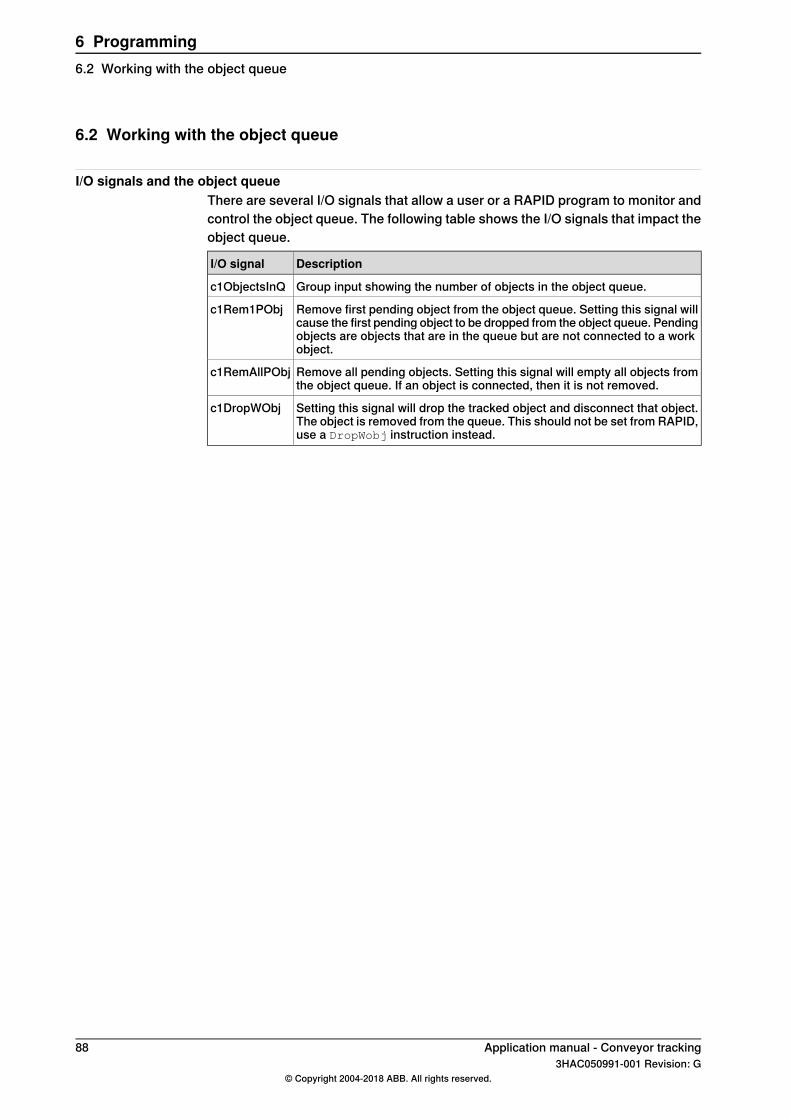
6.2 Working with the object queue
I/O signals and the object queueThere are several I/O signals that allow a user or a RAPID program to monitor andcontrol the object queue. The following table shows the I/O signals that impact theobject queue.
DescriptionI/O signal
Group input showing the number of objects in the object queue.c1ObjectsInQ
Remove first pending object from the object queue. Setting this signal willcause the first pending object to be dropped from the object queue. Pendingobjects are objects that are in the queue but are not connected to a workobject.
c1Rem1PObj
Remove all pending objects. Setting this signal will empty all objects fromthe object queue. If an object is connected, then it is not removed.
c1RemAllPObj
Setting this signal will drop the tracked object and disconnect that object.The object is removed from the queue. This should not be set from RAPID,use a DropWobj instruction instead.
c1DropWObj
88 Application manual - Conveyor tracking3HAC050991-001 Revision: G
© Copyright 2004-2018 ABB. All rights reserved.
6 Programming6.2 Working with the object queue

6.3 Activating the conveyor
ActivationAs an additional axis and mechanical unit the conveyor must be activated beforeit can be used for work object coordination. The usual ActUnit instruction is usedto activate the conveyor and DeactUnit can be used to deactivate the conveyor.By default, the conveyor is installed non-active on start. The conveyor can beconfigured to always be active at start. See Type Mechanical Unit on page 104.
Automatic connection on activation (DSQC377 only)When a conveyor mechanical unit is activated, it first checks the state of theDSQC377B to see if the object was previously connected. If the DSQC377B, viathe I/O signal c1Connected, indicates connection, then the object on the conveyorwill automatically be connected on activation. The purpose of this feature is toautomatically reconnect in case of a power failure with power backup on theDSQC377B.
Application manual - Conveyor tracking 893HAC050991-001 Revision: G
© Copyright 2004-2018 ABB. All rights reserved.
6 Programming6.3 Activating the conveyor
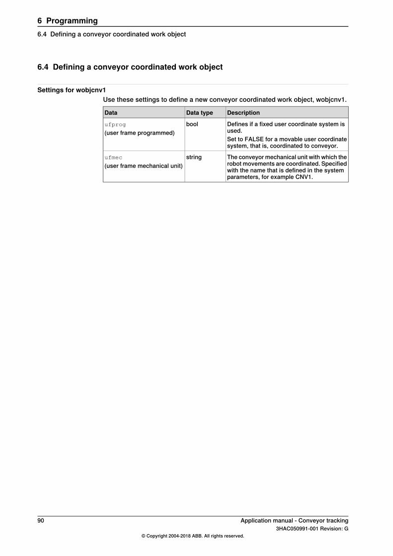
6.4 Defining a conveyor coordinated work object
Settings for wobjcnv1Use these settings to define a new conveyor coordinated work object, wobjcnv1.
DescriptionData typeData
Defines if a fixed user coordinate system isused.
boolufprog
(user frame programmed)Set to FALSE for a movable user coordinatesystem, that is, coordinated to conveyor.
The conveyor mechanical unit with which therobot movements are coordinated. Specifiedwith the name that is defined in the systemparameters, for example CNV1.
stringufmec
(user frame mechanical unit)
90 Application manual - Conveyor tracking3HAC050991-001 Revision: G
© Copyright 2004-2018 ABB. All rights reserved.
6 Programming6.4 Defining a conveyor coordinated work object
6.5 Waiting for a work object
Waiting for a work objectMotions that should be coordinated with the conveyor cannot be programmed untilan object on the conveyor has been connected with a WaitWObj instruction.If the object on the conveyor is already connected from a previous WaitWObj orif connection was established during activation, then execution of a secondWaitWObj instruction will cause an error. This error can be handled in an errorhandler.See WaitWObj - Wait for work object on conveyor on page 107.
Application manual - Conveyor tracking 913HAC050991-001 Revision: G
© Copyright 2004-2018 ABB. All rights reserved.
6 Programming6.5 Waiting for a work object

6.6 Programming the conveyor coordinated motion
Programming the conveyor1 Create a program with the following instructions:
ActUnit CNV1;
ConfL/Off;
MoveL waitp, v1000, fine, tool;
WaitWObj wobjcnv1;
2 Single-step the program past the WaitWObj instruction.If there is an object already in the start window on the conveyor then theinstruction will return, else execution will stop while waiting for an object onthe conveyor.
3 Run the conveyor until a work object is created.The program exits the WaitWObj and is now connected to the object. Stopthe conveyor with the object in an accessible position on the workspace.
4 Program the MoveL, MoveC, PaintL, or PaintC instructions using thewobjcnv1 conveyor coordinated work object.
5 End the coordinated motion with a fixed-frame work object (not coordinatedto the conveyor). Note that this is the only way to end the use of the workobject.
6 Add a DropWObj wobjcnv1; instruction.7 If this is the end of the program, or the conveyor is no longer needed, then
add a DeactUnit CNV1; instruction.
ExampleThe following program shows an example for a conveyor tracking program.
ConfL\Off;
MoveJ p0, vmax, fine, tool1;
ActUnit CNV1;
WaitWObj wobjcnv1;
MoveL p10, v1000, z1, tool1\Wobj:=wobjcnv1;
MoveL p20, v1000, z1, tool1\Wobj:=wobjcnv1;
MoveL p30, v500, z20, tool1\Wobj:=wobjcnv1;
MoveL p40, v500, fine, tool1;
DropWObj wobjcnv1;
MoveL p0, v500, fine;
DeactUnit CNV1;
92 Application manual - Conveyor tracking3HAC050991-001 Revision: G
© Copyright 2004-2018 ABB. All rights reserved.
6 Programming6.6 Programming the conveyor coordinated motion

6.7 Dropping a work object
IntroductionA connected work object can be dropped once conveyor coordinated motion hasended. Make sure that the robot motion is no longer using the conveyor positionswhen the work object is dropped. If motion still requires the positions then a stopwill occur when the object is dropped.It is not necessary to be connected in order to execute a DropWObj instruction.No error will be returned if there was no connected object.
FinepointsConveyor coordinated motion does not end in a finepoint. As long as the workobject is coordinated to the conveyor, the robot motion will be coupled to theconveyor even in a finepoint. A fixed-frame or non-conveyor work object must beused in a motion instruction before dropping the conveyor work object.
Corner zonesTake care when ending coordination in a corner zone and executing the DropWObjinstruction as the work object will be dropped before the robot has left the cornerzone and the motion still requires the conveyor coordinated work object.
Application manual - Conveyor tracking 933HAC050991-001 Revision: G
© Copyright 2004-2018 ABB. All rights reserved.
6 Programming6.7 Dropping a work object

6.8 Entering and exiting conveyor tracking motion in corner zones
Enter and exit coordinated motionOnce a WaitWObj instruction has connected to a work object on the conveyor thenit is possible to enter and exit coordinated motion with the conveyor via cornerzones.
ExampleMoveL p10, v1000, fine, tool1;
WaitWObj wobjcnv1
! enter coordination in zone
MoveL p20, v1000, z50, tool1;
MoveL p30, v500, z1, tool1\Wobj:=wobjcnv1;
MoveL p40, v500, z1, tool1\Wobj:=wobjcnv1;
MoveL p50, v500, z20, tool1\Wobj:=wobjcnv1;
MoveL p60, v1000, z50, tool1;
! exit coordination in zone
MoveL p70, v500, fine, tool1;
DropWObj wobjcnv1;
MoveL p10, v500, fine, tool1;
The move instruction ending coordination must be a fixed work object, for exampleufprog is TRUE.Take care when exiting coordination in a corner zone and executing a DropWObj
instruction.The following example shows an incorrect method for ending coordination in cornerzones:
...
MoveL p50, v500, z20, tool1\Wobj:=wobjcnv1;
MoveL p60, v1000, z50, tool1;
! exit coordination in zone
DropWObj wobjcnv1;
This will cause an error, because the work object is dropped while robot is still incorner zone.
94 Application manual - Conveyor tracking3HAC050991-001 Revision: G
© Copyright 2004-2018 ABB. All rights reserved.
6 Programming6.8 Entering and exiting conveyor tracking motion in corner zones

6.9 Information on FlexPendant
Available information on the FlexPendant
Available in win-dow
Information
JoggingThe conveyor position and speedThe conveyor position is displayed in meters, and the conveyor speedin m/s. The speed will be 0 m/s until an object has passed the syn-chronization switch.
JoggingThe position in millimeters of the conveyor objectThis value will be negative if a Queue Tracking Distance is defined.When an object passes the synchronization switch then the positionwill be automatically updated.
I/OAll signals that are defined for conveyor tracking
Application manual - Conveyor tracking 953HAC050991-001 Revision: G
© Copyright 2004-2018 ABB. All rights reserved.
6 Programming6.9 Information on FlexPendant
6.10 Programming considerations
Performance limitsConveyor tracking will be lost if joint speed limits are reached, particularly insingularities. Ensure that the path during tracking does not exceed the acceleration,speed, and motion capabilities of the robot.
Motion commandsOnly linear and circular motion instructions are allowed for conveyor tracking, thatis MoveL and MoveC.Do not start tracking with a MoveC instruction as the resulting circle diameter willdepend on the conveyor position. Always start tracking with a MoveL.
FinepointsFinepoints are allowed during conveyor tracking. The robot will hold the TCP stillrelative to the conveyor and RAPID execution will continue, see Finepointprogramming on page 97.
ConfLThe RAPID instruction ConfL\Off must be executed before coordination with theconveyor. The purpose is to avoid configuration errors that would otherwise occuras the robot changes configuration during conveyor tracking.
Other RAPID limitationsThe instructions StorePath and RestoPath do not function during conveyortracking.A Search instruction will stop the robot when hit or if the search fails. Make thesearch in the same direction as the conveyor moves and after the search stopscontinue with a move to a safe position. Use an error handler to move to a safeposition if the search fails.EoffsSet, EoffsOn, and EoffsOff have no effect for the conveyor additionalaxis, but can affect conveyor tracking with coordinated track. They also have effecton the sensor taught position.Power fail restart is not possible with the synchronization option.It is possible to use worldzone in conveyor tracking but during tracking the robotmay move outside worldzone borders due to the position adjustment at servo level.Hence, taking margin is recommended when defining the worldzone.
96 Application manual - Conveyor tracking3HAC050991-001 Revision: G
© Copyright 2004-2018 ABB. All rights reserved.
6 Programming6.10 Programming considerations
6.11 Finepoint programming
Example with SetDOWhile tracking the conveyor it is possible to use a finepoint. The following programexample shows how motion may be stopped with respect to the conveyor so thatan I/O signal may be set:
WaitWObj wobjcnv1
MoveL p1, v500, z20, tool1\Wobj:=wobjcnv1;
MoveL p2, v500, fine, tool1\Wobj:=wobjcnv1;
SetDO release_gripper;
WaitTime 0.1;
MoveL p3, v500, z20, tool1\Wobj:=wobjcnv1;
MoveL p4, v500, fine, tool1;
DropWObj wobjcnv1;
In the above example the SetDO will be executed after the robot arrives at p2. Therobot will then track the conveyor for 0.1 seconds while the WaitTime instructionis executed. It will then move to p3 and on to p4 via a corner zone before endingcoordination with a fixed work object (wobj0 in this case).
Example with stoppointdataFinepoints can also be programed with stoppointdata. To make the robot followthe conveyor during 0.1 second, the following program can used.
VAR stoppointdata followtime:=[3,FALSE,[0,0,0,0],0,0.1, "",0,0];
WaitWObj wobjcnv1MoveL p1, v500, z20, tool1\Wobj:=wobjcnv1;
MoveL p2,v500,z1\Inpos:=followtime,tool1\WObj:=wobjcnv1;
SetDO release_gripper;
MoveL p3, v500, z20, tool1\Wobj:=wobjcnv1;
MoveL p4, v500, fine, tool1;
DropWObj wobjcnv1;
For coordinated movements the \Inpos event will not occur for instructions Breakand WaitTime. Instead, use the data type stoppointdata.
Application manual - Conveyor tracking 973HAC050991-001 Revision: G
© Copyright 2004-2018 ABB. All rights reserved.
6 Programming6.11 Finepoint programming

6.12 Operating modes
Operation in manual reduced speed mode (<250 mm/s)When the conveyor is not moving, then the forward and backward hard buttonson the FlexPendant can be used to step through the program. New instructionscan be added and programmed positions can be modified (ModPos).To simplify programming, the conveyor may be moved to new positions betweeninstructions. The robot will return to the correct position when forward or backwardbutton is pressed.The robot will recover as normal if the enabling device is released during motion.The robot cannot perform coordinated motions to the conveyor while in manualreduced speed mode and the conveyor is moving.
Operation in automatic modeOnce a WaitWObj instruction has been executed, then it is no longer possible tostep through the program with forward and backward hard buttons while theconveyor is moving.
DescriptionAction
The robot will stop and no longer track the conveyor if the stop buttonis pressed, or a Break or StopMove instruction is executed, betweenthe WaitWObj and DropWObj instructions. The conveyor coordinatedwork object will not be lost but if the conveyor is moving then the objectwill quickly move out of the working area. Restart from the current instruc-tion is not possible and the program must be restarted from the Mainroutine or with a WaitWObj instruction.
Start and stop
When the emergency stop is pressed the robot will stop immediately. Ifthe program was and restart stopped after a WaitWObj then the coordin-ated work object will not be lost but if the conveyor is moving then theobject will quickly move out of the working area. It is not possible to re-start from the current instruction and the program must be restartedeither from the Main routine or with a WaitWObj instruction.
Emergency stop
Operation in manual full speed mode (100%)Operation in manual mode (100%) is similar to operation in automatic mode. Theprogram can be run by pressing and holding the start button, but once a WaitWObjinstruction has been executed then it is no longer possible to step through theprogram with the forward and backward buttons while the conveyor is moving.
DescriptionAction
When the start button is released, or emergency stop is pressed, therobot will stop immediately. If the program was stopped after a WaitWObjthen the coordinated work object will not be lost but if the conveyor ismoving then the object will quickly move out of the working area. It isnot possible to restart from the current instruction and the program mustbe restarted either from the Main routine or with a WaitWObj instruction.
Stop and restart
98 Application manual - Conveyor tracking3HAC050991-001 Revision: G
© Copyright 2004-2018 ABB. All rights reserved.
6 Programming6.12 Operating modes

7 System parameters7.1 Introduction
About system parametersThis chapter describes system parameters used for all conveyor tracking options.Some parameters that are specific for only one option are presented in procedurecontext if they need to be changed.All basic system parameters and the system parameter principles are listed inTechnical reference manual - System parameters.System parameters are modified using the Configuration Editor in RobotStudioor on the FlexPendant.
Application manual - Conveyor tracking 993HAC050991-001 Revision: G
© Copyright 2004-2018 ABB. All rights reserved.
7 System parameters7.1 Introduction
7.2 Topic I/O
Type Fieldbus Command (DSQC377 only)The instance is named Qtrack1. See Calibrating CountsPerMeter (DSQC377) onpage 71, and Defining conveyor start window and sync separation on page 76.
DescriptionParameter
Gives the number of quadrature pulses per meter of motion of the con-veyor. Should be in the range of 5000-10000 for linear conveyors.
CountsPerMeter
Sync signal separation (meters), this distance defines the minimum dis-tance that the conveyor must move after a sync signal before a new syncsignal is accepted as a valid object.
SyncSeparation
The queue tracking distance (meters) defines the placement of the 0.0meter point relative to the synchronization switch on the conveyor. Allobjects in this distance are tracked. The position returned for the objectwill be negative, relative to the 0.0 m point.
QueueTrckDist
All objects in this distance are tracked, but connection is not alloweduntil an object has passed 0.0 meters.
This distance defines the start window (meters). The start window definesthe area that if a program starts using an object within the window, thenall program coordination can end before the maximum distance or workarea is reached. All objects within this window are tracked and are eligiblefor use in a coordinated work object. A WaitWObj instruction will connectto the first object in the window.
StartWinWidth
Specifies the location of the real part of the poles in the left-half plane(in Hz). This is the break frequency for the speed filters in the encoderinterface and regulates how hard the speed is filtered in the DSQC377B.For stop and go conveyors this parameter should be set between 10 and15 Hz to have a good accuracy during stop and start.
IIRFFP
100 Application manual - Conveyor tracking3HAC050991-001 Revision: G
© Copyright 2004-2018 ABB. All rights reserved.
7 System parameters7.2 Topic I/O

7.3 Topic Process
Type Conveyor systemsThe instance is named CNV1. See Avoiding robot reach problems on page77, andDefining the robot adjustment speed on page 79.
DescriptionParameter
The speed (in mm/s) at which the robot should catch up to the conveyor.It must be higher than the conveyor speed or the robot may never catchup to the conveyor.The adjustment speed must not be higher than 130%of conveyor speed to reduce perturbations on robot speed.
Adjustmentspeed
The minimum distance (in millimeters) that a connected object can havebefore being automatically dropped. If an object is dropped during co-ordinated motion, then the motion is stopped and an error is produced.Note that if the minimum distance is set to a positive value, then all ob-jects are dropped as soon as they are connected.
minimum dis-tance
The maximum distance (in millimeters) that a connected object can havebefore being automatically dropped. If an object is dropped during co-ordinated motion, then the motion is stopped and an error is generated.
maximum dis-tance
The number of samples used to ramp down the correction when trackingis stopped.
Stop ramp
The default value of this parameter is 5, and this is a suitable setting foran IRB 360 with payload in the range 0-1 kg. For an IRB 360 with payload1-8 kg, the value of this parameter should be increased to avoid vibrationsand overload of the mechanical structure. A value of at least 10 shouldbe chosen for a robot with 8 kg payload.When tracking with a track axis this parameter should be increased to30.For a robot switching between conveyors increasing the stop ramp willincrease the distance needed to reach accurate tracking on next convey-or. For example, for an IRB 360 10 steps of 12 ms at 5 m/s this means0.6 meters.
The number of samples used to ramp up the correction when trackingis started.
Start ramp
The default value of this parameter is 5, and this is a suitable setting foran IRB 360 with payload in the range 0-1 kg. For an IRB 360 with payload1-8 kg, this parameter should be increased to avoid vibrations andoverload of the mechanical structure. A value of at least 10 should bechosen for a robot with 8 kg payload.When tracking with a high speed conveyor this parameter can be in-creased.During the ramping the accuracy of tracking is not reached so be carefulwhen increasing this parameter. For an IRB 360 the best choice is to usethe default value (5) if the load is not higher than 1 kg.When switching between 2 conveyors with short distance between pickand place the use of time interpolation is the optimal solution. For ex-ample, put the robot in a wait position just above the pick conveyor witha very short distance to pick position. In this case a low speed or timeinterpolation should also be used.
Continues on next pageApplication manual - Conveyor tracking 1013HAC050991-001 Revision: G
© Copyright 2004-2018 ABB. All rights reserved.
7 System parameters7.3 Topic Process

DescriptionParameter
The maximum acceleration (in mm/s2) at which robot should catch upto the conveyor. By default no limitation.
Adjustment accel
For big robots and heavy load or limited robot acceleration (like use ofAccSet or PathAccLim) it can be necessary to set Adjustment accelaccording to the robot performances.With robot on track or trolley tracking with the track the performance ofthe track is automatically used. This parameter must be adjusted whenthe robot cannot continue its path but remains tracking the same positionon the conveyor.For big robots like IRB 6600 Adjustment accel should be set around 1000if conveyor speed is higher than 150 mm/s.
The number of samples used for average filter of conveyor speed. Max-imum value is 50. Default value 1, which equals no filter. Should be usedonly in case of high level of noise on conveyor speed and speed reductionon robot due to this noise.
Speed filterlength
Specifies the acceleration dependent filter. Default value is 1 m/s2 . Tovalue get good accuracy during acceleration this value should be setequal to the maximum acceleration of the conveyor. A low value meansharder filtering. If there is a problem with noise this parameter shouldbe reduced. If an IRB 360 is used for fast picking this parameter shouldbe set to 0, this will turn off the filtering to improve the response times.
Acc dependentfilter
Defines how fast the robot should adjust the speed to the conveyorspeed. Default value is 0.8. For IRB 360 this can be reduced to 0.5 toimprove the accuracy in fast pick and place applications with low payload(0-1 kg). A too low value might result in jerky movements.
syncfilter ratio
Type Conveyor Ici (DSQC2000)
DescriptionParameter
Gives the number of quadrature pulses per meter of motion of the con-veyor. Should be in the range of 5000-10000 for linear conveyors.
CountsPerMeter
The queue tracking distance (meters) defines the placement of the 0.0meter point relative to the synchronization switch on the conveyor. Allobjects in this distance are tracked. The position returned for the objectwill be negative, relative to the 0.0 m point.
QueueTrckDist
All objects in this distance are tracked, but connection is not alloweduntil an object has passed 0.0 meters.
This distance defines the start window (meters). The start window definesthe area that if a program starts using an object within the window, thenall program coordination can end before the maximum distance or workarea is reached. All objects within this window are tracked and are eligiblefor use in a coordinated work object. A WaitWObj instruction will connectto the first object in the window.
StartWinWidth
Defines how often the system reads the speed and position of the con-veyor from the I/O system.
PosUpdateTime
Type Can interface (DSQC377)The instance is named CAN1. The type Conveyor can sensor is used for the optionConveyor Tracking. The option Indexing Conveyor Control uses the type ConveyorInternal, see Type Conveyor Internal on page 164.
DescriptionParameter
Name of the I/O unit.Eio unit name
Continues on next page102 Application manual - Conveyor tracking
3HAC050991-001 Revision: G© Copyright 2004-2018 ABB. All rights reserved.
7 System parameters7.3 Topic ProcessContinued
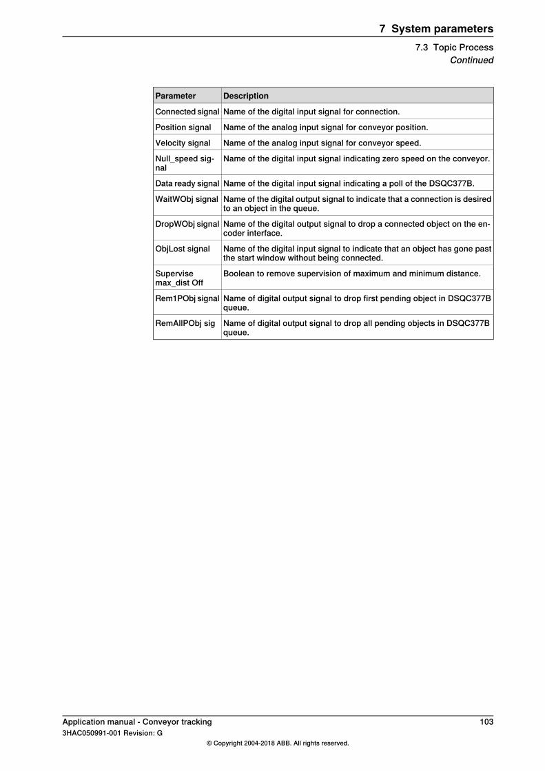
DescriptionParameter
Name of the digital input signal for connection.Connected signal
Name of the analog input signal for conveyor position.Position signal
Name of the analog input signal for conveyor speed.Velocity signal
Name of the digital input signal indicating zero speed on the conveyor.Null_speed sig-nal
Name of the digital input signal indicating a poll of the DSQC377B.Data ready signal
Name of the digital output signal to indicate that a connection is desiredto an object in the queue.
WaitWObj signal
Name of the digital output signal to drop a connected object on the en-coder interface.
DropWObj signal
Name of the digital input signal to indicate that an object has gone pastthe start window without being connected.
ObjLost signal
Boolean to remove supervision of maximum and minimum distance.Supervisemax_dist Off
Name of digital output signal to drop first pending object in DSQC377Bqueue.
Rem1PObj signal
Name of digital output signal to drop all pending objects in DSQC377Bqueue.
RemAllPObj sig
Application manual - Conveyor tracking 1033HAC050991-001 Revision: G
© Copyright 2004-2018 ABB. All rights reserved.
7 System parameters7.3 Topic Process
Continued

7.4 Topic Motion
Type Mechanical UnitThe instance is named CNV1. See Defining the mechanical unit parameters onpage 80, and Activating the conveyor on page 89.
DescriptionParameter
The name of the unit, usually CNV1, CNV2 etc.NameThis name is used in the Jogging window and from the program, forexample when a unit should be activated.
Defines if the conveyor should be activated automatically at start.
Note
This parameter should not be used when combining synchronized andun-synchronized mode, see Combining synchronized and un-synchron-ized mode on page 193.
Activate at Star-tup
Defines if the conveyor is allowed to be deactivated.Deactivation For-bidden
Type Motion PlannerThe instance is named motion_planner. See Regulating CPU load and accuracyon page 80.
DescriptionParameter
The parameter corresponds in some sense to the distance between twopoints in the path. Increasing path resolution means increasing the dis-tance, which leads to a decrease in the resolution of the path.
Path Resolution
Determines how often the process path information is calculated.Process UpdateTime
Defines how long the robot waits when starting from a finepoint, that ishow many positions will be calculated in advance by the motion planner.
Use spline para-meters
Default value is motion_planner_1 for the first robot.Using 3steps mp1 will give a shorter time when starting from finepointbut with the risk that sometimes the robot will stop with warning 50024(Corner zone executed as finepoint) on first move. mp1 stands for mo-tion planner 1, that is, robot 1.
Type RobotThe instance is namedROB_1,ROB_2 etc. SeeAdditional adjustments on page80,and Configuring a track motion to follow a conveyor on page 81.
DescriptionParameter
Defines how often corrections of robot positions are done. Default is 1.Increasing the value gives corrections more often. Should be set to 2 or3 to get good accuracy during conveyor acceleration.
Corvec correc-tion level
For IRB 360 with high payloads (6-8 kg), and for big robots like IRB 6600,it should be set to 1.
If Yes, then the robot will track the conveyor without using the track axiseven if robot is coordinated with the track. Default value is No.
Track ConveyorWith Robot
Continues on next page104 Application manual - Conveyor tracking
3HAC050991-001 Revision: G© Copyright 2004-2018 ABB. All rights reserved.
7 System parameters7.4 Topic Motion
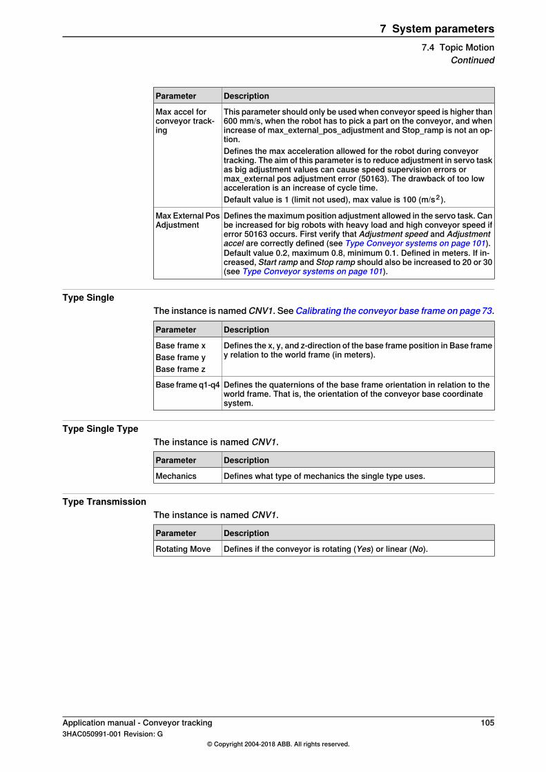
DescriptionParameter
This parameter should only be used when conveyor speed is higher than600 mm/s, when the robot has to pick a part on the conveyor, and whenincrease of max_external_pos_adjustment and Stop_ramp is not an op-tion.
Max accel forconveyor track-ing
Defines the max acceleration allowed for the robot during conveyortracking. The aim of this parameter is to reduce adjustment in servo taskas big adjustment values can cause speed supervision errors ormax_external pos adjustment error (50163). The drawback of too lowacceleration is an increase of cycle time.Default value is 1 (limit not used), max value is 100 (m/s2 ).
Defines the maximum position adjustment allowed in the servo task. Canbe increased for big robots with heavy load and high conveyor speed iferror 50163 occurs. First verify that Adjustment speed and Adjustmentaccel are correctly defined (see Type Conveyor systems on page 101).Default value 0.2, maximum 0.8, minimum 0.1. Defined in meters. If in-creased, Start ramp and Stop ramp should also be increased to 20 or 30(see Type Conveyor systems on page 101).
Max External PosAdjustment
Type SingleThe instance is namedCNV1. SeeCalibrating the conveyor base frame on page73.
DescriptionParameter
Defines the x, y, and z-direction of the base frame position in Base framey relation to the world frame (in meters).
Base frame xBase frame yBase frame z
Defines the quaternions of the base frame orientation in relation to theworld frame. That is, the orientation of the conveyor base coordinatesystem.
Base frame q1-q4
Type Single TypeThe instance is named CNV1.
DescriptionParameter
Defines what type of mechanics the single type uses.Mechanics
Type TransmissionThe instance is named CNV1.
DescriptionParameter
Defines if the conveyor is rotating (Yes) or linear (No).Rotating Move
Application manual - Conveyor tracking 1053HAC050991-001 Revision: G
© Copyright 2004-2018 ABB. All rights reserved.
7 System parameters7.4 Topic Motion
Continued

This page is intentionally left blank

8 RAPID reference8.1 Instructions
8.1.1 WaitWObj - Wait for work object on conveyor
DescriptionWaitWObj (Wait Work Object) connects to a work object in the start window onthe conveyor mechanical unit.
ExampleWaitWObj wobj_on_cnv1;
The program connects to the first object in the object queue that is within the startwindow on the conveyor. If there is no object in the start window then executionstops and waits for an object.
ArgumentsWaitWObj WObj [\RelDist][\MaxTime][\TimeFlag]
WObj
Work ObjectData type: wobjdataThe moving work object (coordinate system) to which the robot position in theinstruction is related. The mechanical unit conveyor is to be specified by the ufmecin the work object.
[\RelDist]
Relative DistanceData type: numWaits for an object to enter the start window and go beyond the distance specifiedby the argument. If the work object is already connected, then execution stopsuntil the object passes the distance. If the object has already gone past the relativedistance then execution continues.
[\MaxTime]
Maximum TimeData type: numThe maximum period of waiting time permitted, expressed in seconds. If this timeruns out before the sensor connection or relative distance is reached, the errorhandler will be called, if there is one, with the error code ERR_WAIT_MAXTIME. Ifthere is no error handler, the execution will be stopped.
[\TimeFlag]
Timeout FlagData type: bool
Continues on next pageApplication manual - Conveyor tracking 1073HAC050991-001 Revision: G
© Copyright 2004-2018 ABB. All rights reserved.
8 RAPID reference8.1.1 WaitWObj - Wait for work object on conveyor
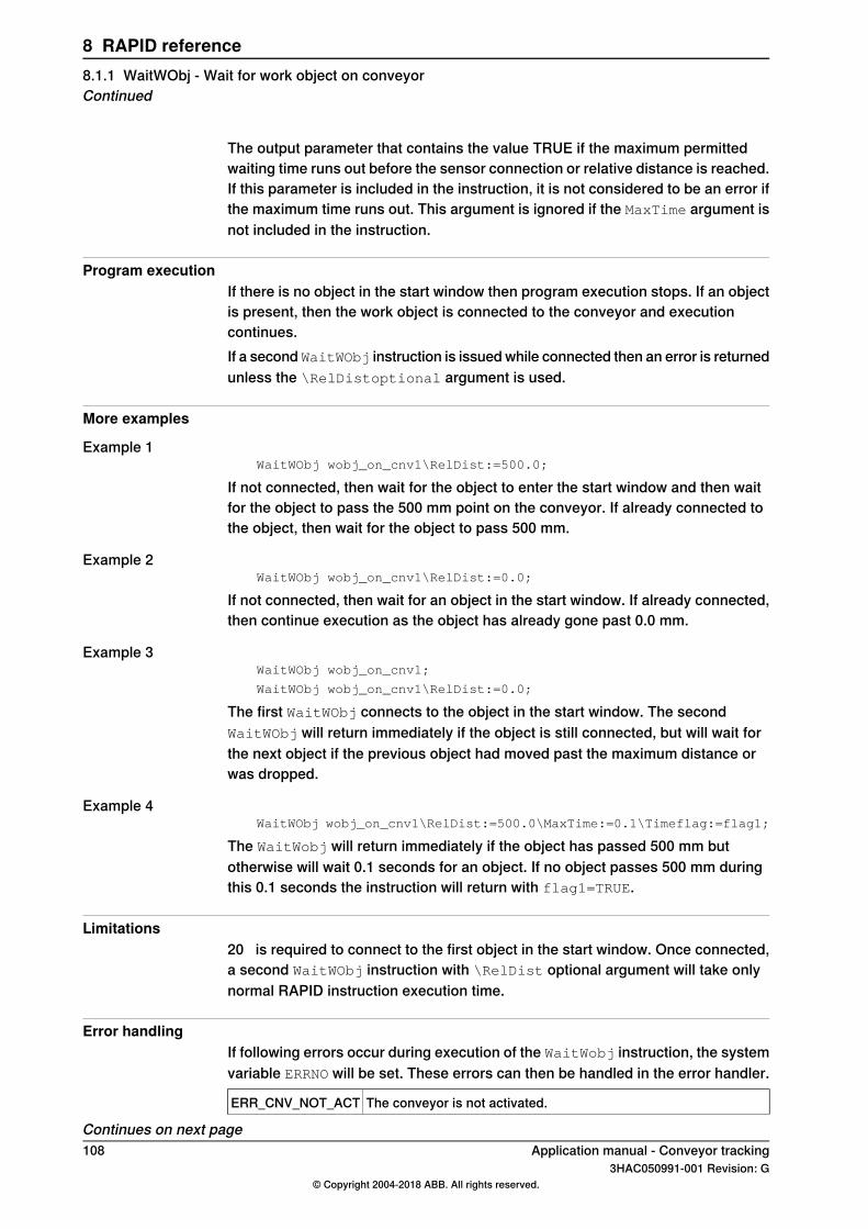
The output parameter that contains the value TRUE if the maximum permittedwaiting time runs out before the sensor connection or relative distance is reached.If this parameter is included in the instruction, it is not considered to be an error ifthe maximum time runs out. This argument is ignored if the MaxTime argument isnot included in the instruction.
Program executionIf there is no object in the start window then program execution stops. If an objectis present, then the work object is connected to the conveyor and executioncontinues.If a second WaitWObj instruction is issued while connected then an error is returnedunless the \RelDistoptional argument is used.
More examples
Example 1WaitWObj wobj_on_cnv1\RelDist:=500.0;
If not connected, then wait for the object to enter the start window and then waitfor the object to pass the 500 mm point on the conveyor. If already connected tothe object, then wait for the object to pass 500 mm.
Example 2WaitWObj wobj_on_cnv1\RelDist:=0.0;
If not connected, then wait for an object in the start window. If already connected,then continue execution as the object has already gone past 0.0 mm.
Example 3WaitWObj wobj_on_cnv1;
WaitWObj wobj_on_cnv1\RelDist:=0.0;
The first WaitWObj connects to the object in the start window. The secondWaitWObj will return immediately if the object is still connected, but will wait forthe next object if the previous object had moved past the maximum distance orwas dropped.
Example 4WaitWObj wobj_on_cnv1\RelDist:=500.0\MaxTime:=0.1\Timeflag:=flag1;
The WaitWobj will return immediately if the object has passed 500 mm butotherwise will wait 0.1 seconds for an object. If no object passes 500 mm duringthis 0.1 seconds the instruction will return with flag1=TRUE.
Limitations20 is required to connect to the first object in the start window. Once connected,a second WaitWObj instruction with \RelDist optional argument will take onlynormal RAPID instruction execution time.
Error handlingIf following errors occur during execution of the WaitWobj instruction, the systemvariable ERRNO will be set. These errors can then be handled in the error handler.
The conveyor is not activated.ERR_CNV_NOT_ACT
Continues on next page108 Application manual - Conveyor tracking
3HAC050991-001 Revision: G© Copyright 2004-2018 ABB. All rights reserved.
8 RAPID reference8.1.1 WaitWObj - Wait for work object on conveyorContinued

The WaitWobj instruction is already connected.ERR_CNV_CONNECT
The object that the instruction WaitWobj was waiting for has beendropped by another task (DSQC377B: an object had passed thestart window).
ERR_CNV_DROPPED
The object did not come in time and there is no Timeflag.ERR_WAIT_MAXTIME
SyntaxWaitWObj
[ WObj ':=']< persistent (PERS) of wobjdata> ';'
[ '\' RelDist ':=' < expression (IN) of num > ]
[ '\' MaxTime ':=' <expression (IN) of num>]
[ '\' TimeFlag ':=' <variable (VAR) of bool>] ';'
Related information
SeeFor information about
DropWObj - Drop work object on conveyoron page 110
DropWObj
Technical referencemanual - RAPID Instruc-tions, Functions and Data types
The data types wobjdata, num, and bool
Application manual - Conveyor tracking 1093HAC050991-001 Revision: G
© Copyright 2004-2018 ABB. All rights reserved.
8 RAPID reference8.1.1 WaitWObj - Wait for work object on conveyor
Continued

8.1.2 DropWObj - Drop work object on conveyor
DescriptionDropWObj (Drop Work Object) is used to disconnect from the current object andthe program is ready for the next.
ExampleMoveL *, v1000, z10, tool, \WObj:=wobj_on_cnv1;
MoveL *, v1000, fine, tool, \WObj:=wobj0;
DropWObj wobj_on_cnv1;
MoveL *, v1000, z10, tool, \WObj:=wobj0;
ArgumentsDropWObj WObj
WObj
Work ObjectData type: wobjdataThe moving work object (coordinate system) to which the robot position in theinstruction is related. The mechanical unit conveyor is to be specified by the ufmecin the work object.
Program executionDropping the work object means that the object is not longer tracked. The objectis removed from the object queue and cannot be recovered.
LimitationsIf the instruction is issued while the robot is actively using the conveyor coordinatedwork object then the motion stops.The instruction can be issued only after a fixed work object has been used in thepreceding motion instructions with either a fine point or several (>1) corner zones.
SyntaxDropWObj
[ WObj ':='] < persistent (PERS) of wobjdata> ';'
Related information
SeeFor information about
WaitWObj - Wait for work object on conveyoron page 107
WaitWObj
Technical referencemanual - RAPID Instruc-tions, Functions and Data types
The data type wobjdata
110 Application manual - Conveyor tracking3HAC050991-001 Revision: G
© Copyright 2004-2018 ABB. All rights reserved.
8 RAPID reference8.1.2 DropWObj - Drop work object on conveyor
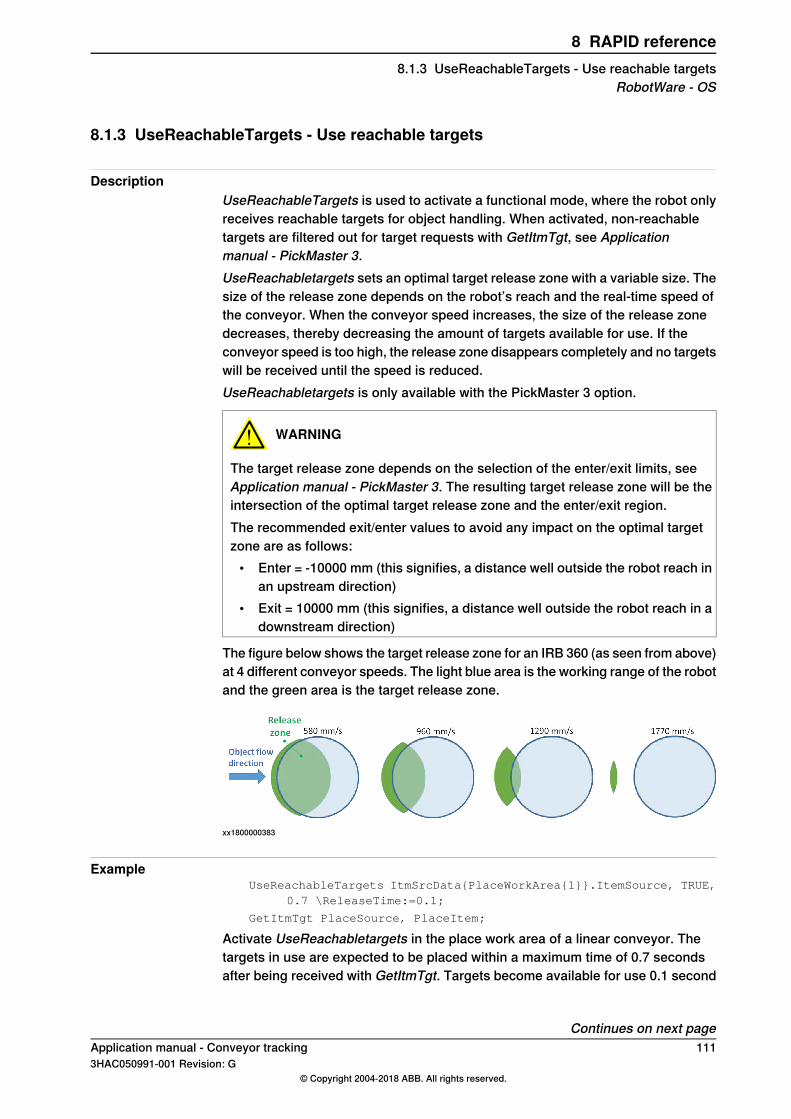
8.1.3 UseReachableTargets - Use reachable targets
DescriptionUseReachableTargets is used to activate a functional mode, where the robot onlyreceives reachable targets for object handling. When activated, non-reachabletargets are filtered out for target requests with GetItmTgt, see Applicationmanual - PickMaster 3.UseReachabletargets sets an optimal target release zone with a variable size. Thesize of the release zone depends on the robot’s reach and the real-time speed ofthe conveyor. When the conveyor speed increases, the size of the release zonedecreases, thereby decreasing the amount of targets available for use. If theconveyor speed is too high, the release zone disappears completely and no targetswill be received until the speed is reduced.UseReachabletargets is only available with the PickMaster 3 option.
WARNING
The target release zone depends on the selection of the enter/exit limits, seeApplication manual - PickMaster 3. The resulting target release zone will be theintersection of the optimal target release zone and the enter/exit region.The recommended exit/enter values to avoid any impact on the optimal targetzone are as follows:
• Enter = -10000 mm (this signifies, a distance well outside the robot reach inan upstream direction)
• Exit = 10000 mm (this signifies, a distance well outside the robot reach in adownstream direction)
The figure below shows the target release zone for an IRB 360 (as seen from above)at 4 different conveyor speeds. The light blue area is the working range of the robotand the green area is the target release zone.
xx1800000383
ExampleUseReachableTargets ItmSrcData{PlaceWorkArea{1}}.ItemSource, TRUE,
0.7 \ReleaseTime:=0.1;
GetItmTgt PlaceSource, PlaceItem;
Activate UseReachabletargets in the place work area of a linear conveyor. Thetargets in use are expected to be placed within a maximum time of 0.7 secondsafter being received with GetItmTgt. Targets become available for use 0.1 second
Continues on next pageApplication manual - Conveyor tracking 1113HAC050991-001 Revision: G
© Copyright 2004-2018 ABB. All rights reserved.
8 RAPID reference8.1.3 UseReachableTargets - Use reachable targets
RobotWare - OS

before they enter robot reach. Then, the targets remain available for use until theyleave the release zone.
ArgumentsUseReachableTargets ItemSource, Enable, UsageTime [\ReleaseTime]
Item Source
ItemSourceData type: itmsrcThe item source where UseReachabletargets is activated.
Enable
EnableData type: boolThis activates/deactivates UseReachabletargets.
Usage Time
UsageTimeData type: numThe expected usage time of the targets. This is the time between receiving thetarget with GetItmTgt, until the object is handled (for example picked) by the robot(acknowledge time). The actual usage time is continuously measured and themaximum measured usage time can be received withGetMaxUsageTime. To avoidreach errors, the UsageTime value should be defined as a sum of the maximummeasured usage time and a margin. For example, set UsageTime = Maximummeasured usage time + 0.1 second. The drawback of having a large safety marginis an unnecessary reduction of the target release zone, which may decrease thepick rate.
[\ReleaseTime]
Release TimeData type: numThe ReleaseTime defines the time when the targets enter the release zone, beforeentering robot reach. If the value is negative, targets enter the release zone afterthey enter robot reach. A value of 0.1 or less is recommended to avoid reach errors.A higher value can be useful to handle high speed conveyors. The drawback of ahigher value is an increasing risk of having upstream reach errors at low speeds.
Note
It is possible to change UsageTime or ReleaseTime at any time. For example, atemporary reduction in the robot speed requires a longer usage time to avoidreach errors.
SyntaxUseReachableTargets
[ItemSource ':=' ] <variable (VAR) of itmsrc>,
[Enable ':=' ] <var or pers (IN) of bool>
Continues on next page112 Application manual - Conveyor tracking
3HAC050991-001 Revision: G© Copyright 2004-2018 ABB. All rights reserved.
8 RAPID reference8.1.3 UseReachableTargets - Use reachable targetsRobotWare - OSContinued

[UsageTime ':=' ] <var or pers (IN) of num>
[\ReleaseTime ':=' ] <expression (IN) of num>;
Application manual - Conveyor tracking 1133HAC050991-001 Revision: G
© Copyright 2004-2018 ABB. All rights reserved.
8 RAPID reference8.1.3 UseReachableTargets - Use reachable targets
RobotWare - OSContinued
8.1.4 GetMaxUsageTime - Get max measured usage time
DescriptionGetMaxUsageTime is used to get the maximum measured usage time of thepreviously handled objects. It is the time between receiving a target with GetItmTgt,until the object is handled by the robot (acknowledge time). The actual usage timeis continuously measured for each handled object. GetMaxUsageTime is onlyavailable with the PickMaster 3 option.
ExampleVAR num usetime;
usetime := GetMaxUsageTime(ItmSrcData{PickWorkArea{1}}.ItemSource);
usetime is the the maximum measured usage time since starting production orsince executing ResetMaxUsageTime.
Return valueData type: numThe maximum measured usage time since starting production or since executingResetMaxUsageTime.
ArgumentsGetMaxUsageTime (ItemSource)
Item Source
ItemSourceData type: itmsrcThe item source.
Error handlingThe following recoverable errors can be generated. They can be handled in anerror handler. The system variable ERRNO will be set to:
The itmsrc is undefined.ERR_ITMSRC_UNDEF
SyntaxGetMaxUsageTime '('[ItemSource ':=' ] <variable (VAR) of itmsrc>
')';
This function returns the value of the data in num type.
114 Application manual - Conveyor tracking3HAC050991-001 Revision: G
© Copyright 2004-2018 ABB. All rights reserved.
8 RAPID reference8.1.4 GetMaxUsageTime - Get max measured usage timeRobotWare - OS

8.1.5 ResetMaxUsageTime - Reset max measured usage time
DescriptionResetMaxUsageTime is used to reset the maximum measured usage time of thepreviously handled objects. This is the time between receiving a target withGetItmTgt, until the object is handled by the robot (acknowledge time).ResetMaxUsageTime is only available with the PickMaster 3 option.
ExampleResetMaxUsageTime ItmSrcData{PickWorkArea{1}}.ItemSource;
Resets the maximum usage time for an item source.
ArgumentsResetMaxUsageTime ItemSource
Item Source
ItemSourceData type: itmsrcThe item source.
Error handlingThe following recoverable errors are generated. They are handled in an errorhandler. The system variable ERRNO will be set to:
The itmsrc is undefined.ERR_ITMSRC_UNDEF
SyntaxResetMaxUsageTime[ItemSource ':=' ] <variable (VAR) of itmsrc>;
Application manual - Conveyor tracking 1153HAC050991-001 Revision: G
© Copyright 2004-2018 ABB. All rights reserved.
8 RAPID reference8.1.5 ResetMaxUsageTime - Reset max measured usage time
RobotWare - OS

8.1.6 CnvPredictReach - High speed conveyors
DescriptionThis section describes the CnvPredictReach.sys module that is used to predict ifthe picking and placing positions are within the work area of the IRB 360, whenusing high speed conveyors (speeds higher than 800 mm/s). This module can onlybe used for simple and repeatable picking and placing programs, it cannot be usedwith buffer or stop and go conveyors.
Example: Initialization of data structureRECORD cnvpickeroptimdata
bool Tpumessage;
num firststeppredictionratio;
num maxfirststeppredictiontime;
num secondsteppredictionratio;
num maxsecondsteppredictiontime;
num maxfirstcyclepredictiontime;
bool wait_end_of_pp_movement;
string pickconveyor;
string placeconveyor;
ENDRECORD
Default valueTASK PERS cnvpickeroptimdata defaultcnvpickeroptimdata
:=[FALSE,0.35,0.6,0.3,0.75,0.6,TRUE,"CNV1","CNV2"];
Example: Picking and placingInitialization phase
InitCnvPredictReachSafepos,resettimearea,1,defaultcnvpickeroptimdata;
In the picking program example from Pickmaster you will need to add a call tocheckpick and trigg to pickenter and pickexit.
PROC Pick(num Index)
IF Index > 0 THEN
WObjPick:=ItmSrcData{Index}.Wobj;
GetItmTgt ItmSrcData{Index}.ItemSource,PickTarget;
CheckPick PickTarget.RobTgt,PickAct1,WObjPick;
TriggL\Conc,RelTool(PickTarget.RobTgt,0,0,-ItmSrcData{Index}.OffsZ)
,MaxSpeed,ItmSrcData{Index}.VacuumAct1\T2:=pickenter,z20,PickAct1\WObj:=WObjPick;
TriggL\Conc,PickTarget.RobTgt,LowSpeed,ItmSrcData{Index}.SimAttach1,z5\
Inpos:=ItmSrcData{Index}.TrackPoint,PickAct1\WObj:=WObjPick;
GripLoad ItemLoad;
TriggLRelTool(PickTarget.RobTgt,0,0,-ItmSrcData{Index}.OffsZ),LowSpeed,
ItmSrcData{Index}.Ack\T2:=pickexit,z20,PickAct1\WObj:=WObjPick;
AccSet 100,100;
ELSE
ErrWrite "Missing item distribution", "Cannot pick because no itemdistribution contains current work area." \RL2:="Please checkconfiguration";
Continues on next page116 Application manual - Conveyor tracking
3HAC050991-001 Revision: G© Copyright 2004-2018 ABB. All rights reserved.
8 RAPID reference8.1.6 CnvPredictReach - High speed conveyorsRobotWare - OS

SafeStop;
ENDIF
ERROR
AckItmTgt ItmSrcData{Index}.ItemSource,PickTarget,FALSE\Skip:=TRUE;
GetItmTgt ItmSrcData{Index}.ItemSource,PickTarget;
RETRY;
ENDPROC
Example: Double picking or single placingInitialization phase
InitCnvPredictReachSafepos,resettimearea,1,defaultcnvpickeroptimdata;
For example when using the Pickmaster template, for double picking and singleplacing.
PROC EnumerateWorkAreas()
VAR num PickNumber:=1;
VAR num PlaceNumber:=1;
VAR num OtherNumber:=1;
InitCnvPredictReachSafepos,resettimearea,1,defaultcnvpickeroptimdata;
FOR i FROM 1 TO MaxNoSources DO
IF (ItmSrcData{i}.Used) THEN
IF (ItmSrcData{i}.SourceType = PICK_TYPE) THEN
PickWorkArea{PickNumber}:=i;
WObjPick:=ItmSrcData{i}.Wobj;
IF use_3areas THEN
InitPickArea 1,3,PickAct1 ,WObjPick,SafePos,FALSE;
ELSE
InitPickArea 1,2,PickAct1 ,WObjPick,SafePos,TRUE;
ENDIF
Incr PickNumber;
ELSEIF (ItmSrcData{i}.SourceType = PLACE_TYPE) THEN
PlaceWorkArea{PlaceNumber}:=i;
WObjPlace:=ItmSrcData{i}.Wobj;
InitPickArea 2,1,PickAct1 ,WObjPlace,SafePos,FALSE;
IF use_3areas THEN
InitPickArea 3,2,PickAct1 ,WObjPlace,SafePos,FALSE;
ENDIF
Incr PlaceNumber;
ELSE
OtherWorkArea{OtherNumber}:=i;
Incr OtherNumber;
ENDIF
InitIoaliasfromitmsrc i;
ENDIF
ENDFOR
ENDPROC
InitIoaliasfromitmsrc is simple alias definition for QuickAckfunction
PROC InitIoaliasfromitmsrc(num Index)
Continues on next pageApplication manual - Conveyor tracking 1173HAC050991-001 Revision: G
© Copyright 2004-2018 ABB. All rights reserved.
8 RAPID reference8.1.6 CnvPredictReach - High speed conveyors
RobotWare - OSContinued

IF ItmSrcData{Index}.Wobj.ufmec = "CNV1" THEN
AliasIO aiCnv1PosSigName,aiCnv1Position;
AliasIO aiCnv1SpeedSigName,aiCnv1Speed;
ELSEIF ItmSrcData{Index}.Wobj.ufmec = "CNV2" THEN
AliasIO aiCnv2PosSigName,aiCnv2Position;
AliasIO aiCnv2SpeedSigName,aiCnv2Speed;
ELSEIF ItmSrcData{Index}.Wobj.ufmec = "CNV3" THEN
AliasIO aiCnv3PosSigName,aiCnv3Position;
AliasIO aiCnv3SpeedSigName,aiCnv3Speed;
ELSEIF ItmSrcData{Index}.Wobj.ufmec = "CNV4" THEN
AliasIO aiCnv4PosSigName,aiCnv4Position;
AliasIO aiCnv4SpeedSigName,aiCnv4Speed;
ELSEIF ItmSrcData{Index}.Wobj.ufmec = "CNV5" THEN
AliasIO aiCnv5PosSigName,aiCnv5Position;
AliasIO aiCnv5SpeedSigName,aiCnv5Speed;
ELSEIF ItmSrcData{Index}.Wobj.ufmec = "CNV6" THEN
AliasIO aiCnv6PosSigName,aiCnv6Position;
AliasIO aiCnv6SpeedSigName,aiCnv6Speed;
ENDIF
ENDPROC
!***********************************************************
!
! Function IsQuickAckOk
!
! Checks if it's OK to make a fast acknowledge.
!
!***********************************************************
FUNC bool IsQuickAckOk(num Index)
VAR num CnvPos:=0;
VAR num DropDist:=0;
VAR num RealPos:=0;
VAR bool QuickAckOk:=FALSE;
VAR num SafeDist;
IF ItmSrcData{Index}.Wobj.ufmec = "" THEN
QuickAckOk:=TRUE;
ELSE
SafeDist:=200;
IF ItmSrcData{Index}.Wobj.ufmec = "CNV1" THEN
CnvPos:=aiCnv1Position*1000;
DropDist:=Cnv1DropDist;
SafeDist:=aiCnv1Speed*1000*0.35;
ELSEIF ItmSrcData{Index}.Wobj.ufmec = "CNV2" THEN
CnvPos:=aiCnv2Position*1000;
DropDist:=Cnv2DropDist;
SafeDist:=aiCnv2Speed*1000*0.35;
ELSEIF ItmSrcData{Index}.Wobj.ufmec = "CNV3" THEN
CnvPos:=aiCnv3Position*1000;
DropDist:=Cnv3DropDist;
SafeDist:=aiCnv3Speed*1000*0.35;
ELSEIF ItmSrcData{Index}.Wobj.ufmec = "CNV4" THEN
CnvPos:=aiCnv4Position*1000;
Continues on next page118 Application manual - Conveyor tracking
3HAC050991-001 Revision: G© Copyright 2004-2018 ABB. All rights reserved.
8 RAPID reference8.1.6 CnvPredictReach - High speed conveyorsRobotWare - OSContinued

DropDist:=Cnv4DropDist;
SafeDist:=aiCnv4Speed*1000*0.35;
ELSEIF ItmSrcData{Index}.Wobj.ufmec = "CNV5" THEN
CnvPos:=aiCnv5Position*1000;
DropDist:=Cnv5DropDist;
ELSEIF ItmSrcData{Index}.Wobj.ufmec = "CNV6" THEN
CnvPos:=aiCnv6Position*1000;
DropDist:=Cnv6DropDist;
ENDIF
IF CnvPos < DropDist-SafeDist THEN
QuickAckOk:=TRUE;
ELSE
QuickAckOk:=FALSE;
ENDIF
ENDIF
RETURN QuickAckOk;
ENDFUNC
!**********************************************************
!
! Function QuickAck
!
! Makes a quick acknowledge. Returns FALSE if is
! wasn't possible.
!
! Example:
! PROC Place(num Index)
! Coordinated;
! WObjPlace:=ItmSrcData{Index}.Wobj;
! GetItmTgt ItmSrcData{Index}.ItemSource,PlaceTarget;
! MoveL\Conc,RelTool(PlaceTarget.RobTgt,0,0,-ItmSrcData{Index}
.OffsZ),MaxSpeed,z20,Gripper\WObj:=WObjPlace;
!TriggL\Conc,PlaceTarget.RobTgt,LowSpeed,ItmSrcData{Index}.VacuumRev1\T2:=
ItmSrcData{Index}.VacuumOff1,z5\Inpos:=ItmSrcData{Index}.TrackPoint,Gripper\WObj:=WObjPlace;
! GripLoad load0;
! IF QuickAck(Index, PlaceTarget) THEN
! MoveLRelTool(PlaceTarget.RobTgt,0,0,-ItmSrcData{Index}.OffsZ),LowSpeed,
z20,Gripper\WObj:=WObjPlace;
! ELSE
! TriggL RelTool(PlaceTarget.RobTgt,0,0,-ItmSrcData{Index}.OffsZ)
,LowSpeed,ItmSrcData{Index}.Ack,z20,Gripper\WObj:=WObjPlace;
! ENDIF
! UnCoordinated;
! ENDPROC
!
!
!***********************************************************
FUNC bool QuickAck(num Index, itmtgt ItemTarget \switch Nack)
VAR bool QuickAckOk:=FALSE;
VAR bool AckNack:=TRUE;
Continues on next pageApplication manual - Conveyor tracking 1193HAC050991-001 Revision: G
© Copyright 2004-2018 ABB. All rights reserved.
8 RAPID reference8.1.6 CnvPredictReach - High speed conveyors
RobotWare - OSContinued

IF Present(Nack) THEN
AckNack:=FALSE;
ENDIF
IF IsQuickAckOk(Index) THEN
AckItmTgt ItmSrcData{Index}.ItemSource,ItemTarget,AckNack;
QuickAckOk:=TRUE;
ENDIF
RETURN QuickAckOk;
ENDFUNC
120 Application manual - Conveyor tracking3HAC050991-001 Revision: G
© Copyright 2004-2018 ABB. All rights reserved.
8 RAPID reference8.1.6 CnvPredictReach - High speed conveyorsRobotWare - OSContinued

9 Advanced queue tracking9.1 Introduction to advanced queue tracking
IntroductionWhen queue tracking mode is enabled in the conveyor I/O configuration, the jobqueue is external, which means it can be handled by the RAPID code. If the queuetracking mode is disabled, then the queue is handled internally.
InstallationQueue tracking is disabled by default in the conveyor I/O configuration, as thesignal c1PosInJob is set to 0 (zero). To enable queue tracking, set c1PosInJob to1.
System parametersThe following signals are used for advanced queue tracking and must be definedin the system parameters, topic I/O, type Signal.
DescriptionI/O signal
Group input showing the number of objects in the object queue. Theseobjects have passed the synchronization switch but have not gone out-side the start window.
c1ObjectsInQ
Remove first pending object from the object queue. Setting this signalwill cause the first pending object to be dropped from the object queue.Pending objects are objects that are in the queue but are not connectedto a work object.
c1Rem1PObj
Remove all pending objects. Setting this signal will empty all objectsfrom the object queue. If an object is connected, then it is not removed.
c1RemAllPObj
Setting this signal will drop the tracked object and disconnect that object.The object is removed from the queue. This should not be set fromRAPID, use the DropWobj instruction instead.
c1DropWObj
DI new position from the encoder to enter the job queue.c1NewObjStrobe
GI 32-bit counter value from encoder to main controller.
Note
The 32-bit signal is now default, but the old 16-bit signals are still suppor-ted: c1CntFromEnc1 (low word) and c1CntFromEnc2 (high word).
c1CntFromEnc
DO strobe for a 32-bit position to the conveyor work area from the jobqueue.
c1CntToEncStr
GO 32-bit counter value from main controller to encoder.
Note
The 32-bit signal is now default, but the old 16-bit signals are still suppor-ted: c1CntToEnc1 (low word) and c1CntToEnc2 (high word).
c1CntToEnc
DI scaled-down encoder pulses.c1ScaleEncPuls
DO run this job even if the checkpoint should fail.c1ForceJob
Continues on next pageApplication manual - Conveyor tracking 1213HAC050991-001 Revision: G
© Copyright 2004-2018 ABB. All rights reserved.
9 Advanced queue tracking9.1 Introduction to advanced queue tracking
DescriptionI/O signal
DO send the position to MC to be stored in the job queue. (0 = Queue-tracking disabled. Same mode as DSQC 354)
c1PosInJobQ
DI notifies the main computer that an object has passed out of the startwindow (object lost). If the main process is waiting in a WaitWObj instruc-tion, the program pointer will be moved to the nearest error handler, soappropriate action can be taken, for example pop the job queue.
c1PassedStWin
DI: 0 = Encoder A selected, 1= Encoder B selectedc1EncSelected
DI Encoder A Faultc1EncAFault
DI Encoder B Faultc1EncBFault
DI direction of travelc1DirOfTravel
DI simulating modec1Simulating
DI power up status: Counters have been lost.c1PowerUp-Status
DO puts the conveyor work area in to simulation mode.c1SimMode
DO soft-sync signal. Simulates Sync-input.c1softSyncSig
DO soft-checkpoint signal. Simulates checkpoint input.c1softCheckSig
DO:• 0 = Encoder A selected• 1 = Encoder B selected
c1EncSelec
122 Application manual - Conveyor tracking3HAC050991-001 Revision: G
© Copyright 2004-2018 ABB. All rights reserved.
9 Advanced queue tracking9.1 Introduction to advanced queue trackingContinued

9.2 Working with the object queue
Signal valuesThe option Conveyor Tracking provides several I/O signals that allow a user orRAPID program to monitor and control the object queue. The table in Systemparameters on page 121, shows the I/O signals that impact the object queue. Thecounter values have to do with the queue tracking function. Positions detected onthe encoder node are sent to the main computer to be stored in the job queuehandled by the robot controller. Values are returned to the encoder when objectis ready to be tracked.
Handling the object queue in RAPIDTo handle the object queue in RAPID the program must store the counter valuefor each new object on the conveyor and write it to the conveyor board when theuser wants to track this object.The RAPID program needs the following elements:
SetDO c1PosInJobQ, 1;
! So the board will update the counters
CONNECT NewObj WITH NewObjOnConvey;
ISignalGI c1CntFromEnc, NewObj;
! To save the counters when a new object is detected
TRAP NewObjOnConvey
! Toggle has arrived; Read a new position from input group
ObjectPosition := GInputDnum(c1CntFromEnc);
RETURN;
ENDTRAP
TRAP TrackNewObj
! To track new obj: Write a new reference to output group
SetGO c1CntToEnc, ObjectPosition;
WaitTime 0.02;
! Validate the new reference
PulseDO c1CountToEncStr;
RETURN;
ENDTRAP
Checkpoint function
Checkpoint switchCheck Point Distance is used when running queue tracking. In addition to thenormal sync switch you have a checkpoint switch just before the start window.This switch will check if the object is within the limits set by the checkpoint windowwidth. If not, the object will be discarded from the object queue, unless the signalc1ForceJob is active.The checkpoint signal is connected on input 16.
Continues on next pageApplication manual - Conveyor tracking 1233HAC050991-001 Revision: G
© Copyright 2004-2018 ABB. All rights reserved.
9 Advanced queue tracking9.2 Working with the object queue
Checkpoint parameters
DescriptionParameter
Distance to checkpoint from 0.0Check Point Distance
Tolerance window for the checkpointCheck Point Window Width
Note
Check Point Distance and Check Point Window Width must be set to zero whennot used, or else this functionality can unintentionally drop objects from thequeue.
Scale enc pulseThe ScalingFactor tells after how many counts the signal c1ScaleEncPuls shouldtoggle. So the distance between scale encoder pulses = (ScalingFactor *2)/CountsPerMeterThe maximum value of ScalingFactor is 25000. ScalingFactor and CountsPerMeterbelong to the type Fieldbus Command in the topic I/O. See Type Fieldbus Command(DSQC377 only) on page 100.
Passed start window signalIn some applications it is important to know if an object has gone through the startwindow without being connected. The encoder interface allows the IRC5 softwareto detect when an object has passed the start window without being connectedand is thus lost. The detection of the lost object is done on the next WaitWObjinstruction. The next WaitWObj instruction, following after an object has movedoutside the start window, will return with the error ERR_CNV_DROPPED. This errorcan be handled in the RAPID error handler.The conveyor work area returns a new I/O signal, c1PassStw. This signal will gohigh when the next connect is attempted and one or more objects have left thestart window without being connected.If needed, the automatic use of the c1PassStw signal can be disabled and insteaduse this signal directly in the RAPID application.
Disabling the object lost feature in WaitWObj
The object lost feature is not wanted in all applications as it can limit backwardcompatibility or can complicate the application.To disable the feature, remove the conveyor I/O signal PassStartW. This will stopthe ERR_CNV_DROPPED from occurring on the next WaitWObj instruction. Thec1PassStw signal from the DSQC377B will still go high but the conveyor trackingprocess will no longer be looking for the signal.
Simulation modeThe simulated encoder starts when the simulation signal is set. The simulationencoder counts is set to the real encoder counts when the simulation signal is set.If the simulation signal is reset the encoder value returns to real encoder position.
Continues on next page124 Application manual - Conveyor tracking
3HAC050991-001 Revision: G© Copyright 2004-2018 ABB. All rights reserved.
9 Advanced queue tracking9.2 Working with the object queueContinued

The simulation speed is defined with the parameterSimulationVel in the typeSignal,in the topic I/O.
Application manual - Conveyor tracking 1253HAC050991-001 Revision: G
© Copyright 2004-2018 ABB. All rights reserved.
9 Advanced queue tracking9.2 Working with the object queue
Continued

This page is intentionally left blank

10 Circular conveyor tracking10.1 Introduction to circular conveyor tracking
IntroductionCircular conveyors can be tracked with the optionConveyor Tracking. The principlefor configuring circular conveyor tracking is to define values in radians instead ofmeters. Then configure as described in Installation on page 39, and Configurationand calibration on page 61.This chapter will where there are differences in the configuration compared tolinear conveyors.
ExampleThe figure below shows an example of circular conveyor tracking with exampleunits and distances.
IRB
XIRB
YIRB
Direction ofrotation
Radius = 6 m2.44 rad
maximum distance
StartWinWidth
QueueTrkDist
minimum distanceSync switch
0.0 rad
YX
xx1200001101
40000 counts per radianCountsPerMeterAt 6 m radius, one count = 0.15 mm
-100 milliradiansminimum distanceAt 6 m radius, = -600 mm
Base frame x = 8.0 mConveyor base frameBase frame y = 0.0 mBase frame z = 0.0 m
Continues on next pageApplication manual - Conveyor tracking 1273HAC050991-001 Revision: G
© Copyright 2004-2018 ABB. All rights reserved.
10 Circular conveyor tracking10.1 Introduction to circular conveyor tracking

Base frame q1 = 0.3420The x-axis is rotated 2.44 radfrom the world X (XIRB) Base frame q2 = 0.0000
Base frame q3 = 0.0000Base frame q4 = 0.9397
0.005 radSyncSeparationAt 6 m radius = 30 mm
0.017 radQueueTrkDistAt 6 m radius = 100 mm
420 milliradiansmaximum distanceAt 6 m radius = 2520 mm
0.017 radStartWinWidthAt 6 m radius = 100 mm
128 Application manual - Conveyor tracking3HAC050991-001 Revision: G
© Copyright 2004-2018 ABB. All rights reserved.
10 Circular conveyor tracking10.1 Introduction to circular conveyor trackingContinued

10.2 Encoder type selection and location
PrerequisitesThe goal in selecting an encoder for circular conveyor tracking is to have 0.1 mmto 0.2 mm resolution per count at the maximum radius of conveyor tracking.
ExampleIn the Example on page127, following at a 6 meter radius in order to have 0.15 mmper count, we must have 40,000 counts per radian at the center of the table. Thecounts are quadrature encoded (four counts per pulse), thus the encoder mustgive 10,000 pulses per radian of circular conveyor movement. For a full revolutionthere are 2p radians per revolution, giving a requirement for 10000 × 2p = 62831.85pulses per revolution of the circular conveyor.
Selecting gear ratioIf an encoder with 1000 pulses per revolution is selected, then we require a gearratio of 1 to 62.83185 between the circular conveyor and the encoder shaft.
Note
The maximum value for CountsPerMeter in the encoder software is 50000. Thisshould be considered when selecting gearing and encoder.
Application manual - Conveyor tracking 1293HAC050991-001 Revision: G
© Copyright 2004-2018 ABB. All rights reserved.
10 Circular conveyor tracking10.2 Encoder type selection and location

10.3 Installation and configuration
Software installationThe conveyor work area and conveyor tracking software are connected and installedin the same way as for linear conveyors.
Direction of positive motion from encoderSee the description for linear conveyors, Description on page 70.
Defining CountsPerMeterThe value of the parameter CountsPerMeter should be known from the selectionof the encoder and the gear ratio between the circular conveyor and the encodershaft. If the value is not known, then it is possible to measure the value followingthe same steps as outlined for a linear conveyor with extra equipment for measuringthe change in angle of the conveyor between position_1, and position_2. SeeCalibrating CountsPerMeter (DSQC377) on page 71.
Defining the queue tracking distanceBefore proceeding with conveyor setup and calibration it is necessary to definethe desired queue tracking distance (QueueTrckDist). The queue tracking distanceestablishes the distance between the synchronization switch and the 0.0 rad pointon the circular conveyor. The conveyor work area will keep track of all objects thathave passed the synchronization switch but have not yet passed the 0.0 rad point.See Calibrating CountsPerMeter (DSQC377) on page 71.
130 Application manual - Conveyor tracking3HAC050991-001 Revision: G
© Copyright 2004-2018 ABB. All rights reserved.
10 Circular conveyor tracking10.3 Installation and configuration

10.4 Additional motion settings
Conveyor start window and sync separationFor circular conveyor tracking these distances are defined in radians.
Conveyor maximum and minimum distances
Note
For circular conveyor tracking these distances are defined in milliradians.
Conveyor adjustment speedThe same as for linear conveyors.
Motion System parametersThe same as for linear conveyors.
Mechanical Unit parametersThe same as for linear conveyors.
Transmission and Single Type parametersThe motion configuration of the conveyor must be adjusted to account for a circularmotion of the conveyor. There are two parameters that must be adjusted.
DescriptionTypeParameter
Defines if the conveyor is rotating (Yes) orlinear (No).
TransmissionRotating Move
Defines the mechanical structure of the con-veyor.
Single TypeMechanics
Select EXT_ROT.
Application manual - Conveyor tracking 1313HAC050991-001 Revision: G
© Copyright 2004-2018 ABB. All rights reserved.
10 Circular conveyor tracking10.4 Additional motion settings

10.5 Calibrating the conveyor base frame
Calibration optionsThe accuracy of the circular conveyor tracking depends on the accuracy inspecifying the conveyor base frame. There are two methods to calibrate the baseframe for a circular conveyor:
1 Enter the orientation and position of the base frame based on drawings ofthe robot installation and simple TCP measurements.
2 Use the robot TCP as a measuring tool and measure several points alongthe conveyor with some trigonometric calculations to calculate the conveyorbase frame position and quaternion.
We recommend using the second method, with TCP as measuring tool. See TCPmeasurement method on page 134.
132 Application manual - Conveyor tracking3HAC050991-001 Revision: G
© Copyright 2004-2018 ABB. All rights reserved.
10 Circular conveyor tracking10.5 Calibrating the conveyor base frame

10.6 Manually calibrating the conveyor base frame
OrientationThe definition of the quaternion for conveyor orientation will also define the locationof the 0.0 radian point on the circular conveyor. The direction of the x-axis willdefine the 0.0 radian point while the direction of the z-axis will define the directionof positive rotation using the right-hand-rule.The graphic below shows two installations, one with clockwise rotation and theother with counterclockwise rotation and the corresponding quaternions. In caseswhere the 0.0 rad point is not an even multiple of 90° from the world frame,calculation of the conveyor orientation quaternion must be done using manualcalculations of the quaternion. The TCP can be used to help make measurements,see TCP measurement method on page 134.
0.0 rad 0.0 rad
IRB
XIRB
XIRB
X
Y
IRB
XIRB
XIRB
X
Y
Direction ofrotation Direction of
rotation
QueueTrkDist
xx1200001102
Quaternion 0, 0.7071, -0.7071, 0Quaternion 0.7071, 0, 0, 0.7071
Base frame position and start window start calibrationThe conveyor base frame x, y, and z position must be specified relative to the worldframe. This position must be calculated from the installation drawings or by usingthe robot as a measuring tool. Using the robot, one point can be marked on theedge of the circular conveyor and the TCP position is recorded for several pointsand the center point of the circle can be found. This is described in detail in thefollowing section.
Application manual - Conveyor tracking 1333HAC050991-001 Revision: G
© Copyright 2004-2018 ABB. All rights reserved.
10 Circular conveyor tracking10.6 Manually calibrating the conveyor base frame

10.7 TCP measurement method
RecommendationThis section describes how to use TCP measurements and RAPID programs tocalculate the conveyor base frame position and quaternion for a circular conveyor.This method uses three measured points on the circular conveyor to calculate thecenter of rotation. The three points should be spaced as far apart as possiblearound the periphery.
Calculating the x and y positions for the base frameUse this procedure to calculate the x and y positions for the base frame.
1 Use Wobj0 on the FlexPendant. Pick out a reference point on the circularconveyor, jog the TCP to this point and record p_0.
2 Run the conveyor to another position. Jog the TCP to the reference pointand record p_1.
3 Run the conveyor to a third position, jog the TCP to the reference point andrecord p_2.
4 Use the function CNVUTL_cirCntr with the points p_0, p_1, and p_2, tocalculate the center of the circle, p_centre.The system module cnv_utl.sys can be found in Robotware.
5 Take the x and y values from p_centre and enter them into the base framevalues for the conveyor, converting to meters, see Topic Motion on page104.These are shown in Orientation on page133. The z value will be entered later,once the work object zero position has been chosen.
Continues on next page134 Application manual - Conveyor tracking
3HAC050991-001 Revision: G© Copyright 2004-2018 ABB. All rights reserved.
10 Circular conveyor tracking10.7 TCP measurement method
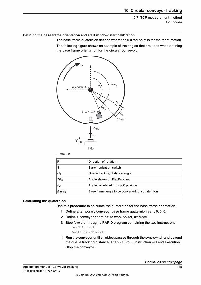
Defining the base frame orientation and start window start calibrationThe base frame quaternion defines where the 0.0 rad point is for the robot motion.The following figure shows an example of the angles that are used when definingthe base frame orientation for the circular conveyor.
IRB
S
0.0 rad
R
XIRB
YIRB
p_centre, X, Y
p_0, X_0, Y_0Qθ
Pθ
Baseθ
TPθ
xx1200001103
Direction of rotationR
Synchronization switchS
Queue tracking distance angleQθ
Angle shown on FlexPendantTPθ
Angle calculated from p_0 positionPθ
Base frame angle to be converted to a quaternionBaseθ
Calculating the quaternionUse this procedure to calculate the quaternion for the base frame orientation.
1 Define a temporary conveyor base frame quaternion as 1, 0, 0, 0.2 Define a conveyor coordinated work object, wobjcnv1.3 Step forward through a RAPID program containing the two instructions:
ActUnit CNV1;
WaitWObj wobjcnv1;
4 Run the conveyor until an object passes through the sync switch and beyondthe queue tracking distance. The WaitWObj instruction will end execution.Stop the conveyor.
Continues on next pageApplication manual - Conveyor tracking 1353HAC050991-001 Revision: G
© Copyright 2004-2018 ABB. All rights reserved.
10 Circular conveyor tracking10.7 TCP measurement method
Continued

5 Using wobjcnv1, move the robot TCP to the desired zero position on thework object and record this point, p_0. Write down the X_0, Y_0, and Z_0coordinates of the point p_0 as shown on the FlexPendant (wobjcnv1 mustbe selected as work object).
6 Write down the angle shown in the Jogging window for the CNV1 conveyor.
This is angle , see example measurement points in Defining the baseframe orientation and start window start calibration on page 135.
7 Calculate P from theX_0 andY_0 coordinates of p_0 and the atan function.X_0 and Y_0 should both be positive when using the atan function. Checkthe value, it may be necessary to add 90 degrees:
8 Calculate the value of Base.
9 Calculate the quaternion for the base frame taking into account the directionof rotation:Counter clockwise rotation:
q1 = cos(Base /2)
q2 = 0.0
q3 = 0.0
q4 = sin(Base /2)
Clockwise rotation:q1 = 0.0
q2 = cos(Base /2)
q3 = –sin(Base /2)
q4 = 0.0
10 Enter the value for z (in meters) from p_0, and the values for the quaternions,q1, q2, q3, and q4, into the base frame for the conveyor, see Topic Motionon page 104.
136 Application manual - Conveyor tracking3HAC050991-001 Revision: G
© Copyright 2004-2018 ABB. All rights reserved.
10 Circular conveyor tracking10.7 TCP measurement methodContinued

11 Accelerating conveyors11.1 Introduction to accelerating conveyors
DescriptionThis section describes how to optimize the tracking performance of acceleratingand decelerating conveyors for the optionConveyor Tracking. This might be neededfor example if good accuracy is needed during start and stop of the conveyor. Toget good accuracy during tracking of accelerating conveyors it is important thatall system parameters in the system are defined correctly. This chapter describesthe parameters that are important for accelerating and decelerating conveyors.See System parameters on page 138.To further improve the accuracy it is possible to predict the speed change of theconveyor. This is done using a special RAPID function together with an I/O signalthat is set just before the acceleration starts. See Predicting speed changes onpage 140.For indexing conveyors, see Indexing conveyors on page 145.
PrerequisitesThe conveyor and encoder must be set up and calibrated correctly, seeConfiguration and calibration on page 61.
Application manual - Conveyor tracking 1373HAC050991-001 Revision: G
© Copyright 2004-2018 ABB. All rights reserved.
11 Accelerating conveyors11.1 Introduction to accelerating conveyors
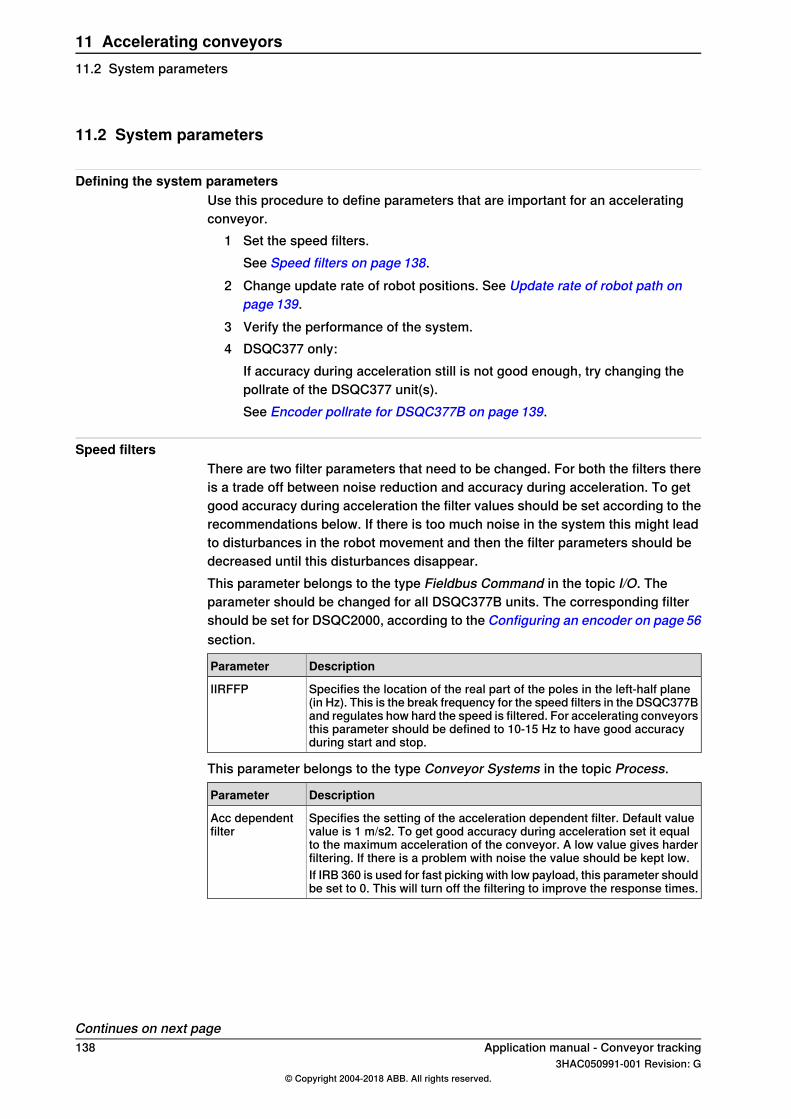
11.2 System parameters
Defining the system parametersUse this procedure to define parameters that are important for an acceleratingconveyor.
1 Set the speed filters.See Speed filters on page 138.
2 Change update rate of robot positions. See Update rate of robot path onpage 139.
3 Verify the performance of the system.4 DSQC377 only:
If accuracy during acceleration still is not good enough, try changing thepollrate of the DSQC377 unit(s).See Encoder pollrate for DSQC377B on page 139.
Speed filtersThere are two filter parameters that need to be changed. For both the filters thereis a trade off between noise reduction and accuracy during acceleration. To getgood accuracy during acceleration the filter values should be set according to therecommendations below. If there is too much noise in the system this might leadto disturbances in the robot movement and then the filter parameters should bedecreased until this disturbances disappear.This parameter belongs to the type Fieldbus Command in the topic I/O. Theparameter should be changed for all DSQC377B units. The corresponding filtershould be set for DSQC2000, according to the Configuring an encoder on page 56section.
DescriptionParameter
Specifies the location of the real part of the poles in the left-half plane(in Hz). This is the break frequency for the speed filters in the DSQC377Band regulates how hard the speed is filtered. For accelerating conveyorsthis parameter should be defined to 10-15 Hz to have good accuracyduring start and stop.
IIRFFP
This parameter belongs to the type Conveyor Systems in the topic Process.
DescriptionParameter
Specifies the setting of the acceleration dependent filter. Default valuevalue is 1 m/s2. To get good accuracy during acceleration set it equalto the maximum acceleration of the conveyor. A low value gives harderfiltering. If there is a problem with noise the value should be kept low.
Acc dependentfilter
If IRB 360 is used for fast picking with low payload, this parameter shouldbe set to 0. This will turn off the filtering to improve the response times.
Continues on next page138 Application manual - Conveyor tracking
3HAC050991-001 Revision: G© Copyright 2004-2018 ABB. All rights reserved.
11 Accelerating conveyors11.2 System parameters
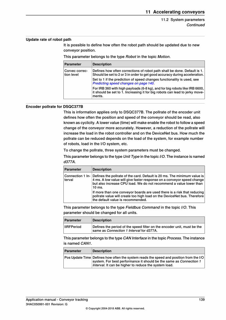
Update rate of robot pathIt is possible to define how often the robot path should be updated due to newconveyor position.This parameter belongs to the type Robot in the topic Motion.
DescriptionParameter
Defines how often corrections of robot path shall be done. Default is 1.Should be set to 2 or 3 in order to get good accuracy during acceleration.
Corvec correc-tion level
Set to 1 if the prediction of speed changes functionality is used, seePredicting speed changes on page 140.For IRB 360 with high payloads (6-8 kg), and for big robots like IRB 6600,it should be set to 1. Increasing it for big robots can lead to jerky move-ments.
Encoder pollrate for DSQC377BThis is information applies only to DSQC377B. The pollrate of the encoder unitdefines how often the position and speed of the conveyor should be read, alsoknown as cyclicity. A lower value (time) will make enable the robot to follow a speedchange of the conveyor more accurately. However, a reduction of the pollrate willincrease the load in the robot controller and on the DeviceNet bus. How much thepollrate can be reduced depends on the load of the system, for example numberof robots, load in the I/O system, etc.To change the pollrate, three system parameters must be changed.This parameter belongs to the typeUnit Type in the topic I/O. The instance is namedd377A.
DescriptionParameter
Defines the pollrate of the card. Default is 20 ms. The minimum value is4 ms. A low value will give faster response on a conveyor speed changebut also increase CPU load. We do not recommend a value lower than10 ms.
Connection 1 In-terval
If more than one conveyor boards are used there is a risk that reducingpollrate value will create too high load on the DeviceNet bus. Thereforethe default value is recommended.
This parameter belongs to the type Fieldbus Command in the topic I/O. Thisparameter should be changed for all units.
DescriptionParameter
Defines the period of the speed filter on the encoder unit, must be thesame as Connection 1 Interval for d377A.
IIRFPeriod
This parameter belongs to the typeCAN Interface in the topicProcess. The instanceis named CAN1.
DescriptionParameter
Defines how often the system reads the speed and position from the I/Osystem. For best performance it should be the same as Connection 1Interval. It can be higher to reduce the system load.
Pos Update Time
Application manual - Conveyor tracking 1393HAC050991-001 Revision: G
© Copyright 2004-2018 ABB. All rights reserved.
11 Accelerating conveyors11.2 System parameters
Continued
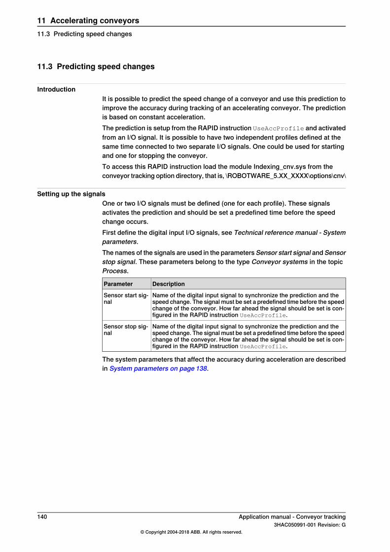
11.3 Predicting speed changes
IntroductionIt is possible to predict the speed change of a conveyor and use this prediction toimprove the accuracy during tracking of an accelerating conveyor. The predictionis based on constant acceleration.The prediction is setup from the RAPID instruction UseAccProfile and activatedfrom an I/O signal. It is possible to have two independent profiles defined at thesame time connected to two separate I/O signals. One could be used for startingand one for stopping the conveyor.To access this RAPID instruction load the module Indexing_cnv.sys from theconveyor tracking option directory, that is, \ROBOTWARE_5.XX_XXXX\options\cnv\
Setting up the signalsOne or two I/O signals must be defined (one for each profile). These signalsactivates the prediction and should be set a predefined time before the speedchange occurs.First define the digital input I/O signals, see Technical reference manual - Systemparameters.The names of the signals are used in the parameters Sensor start signal and Sensorstop signal. These parameters belong to the type Conveyor systems in the topicProcess.
DescriptionParameter
Name of the digital input signal to synchronize the prediction and thespeed change. The signal must be set a predefined time before the speedchange of the conveyor. How far ahead the signal should be set is con-figured in the RAPID instruction UseAccProfile.
Sensor start sig-nal
Name of the digital input signal to synchronize the prediction and thespeed change. The signal must be set a predefined time before the speedchange of the conveyor. How far ahead the signal should be set is con-figured in the RAPID instruction UseAccProfile.
Sensor stop sig-nal
The system parameters that affect the accuracy during acceleration are describedin System parameters on page 138.
140 Application manual - Conveyor tracking3HAC050991-001 Revision: G
© Copyright 2004-2018 ABB. All rights reserved.
11 Accelerating conveyors11.3 Predicting speed changes

11.4 UseAccProfile - Use acceleration profile
DescriptionUseAccProfile is used to predict conveyor movement with constant accelerationor deceleration.The profile uses either the acceleration for the conveyor or the time that it takesfor the conveyor to accelerate or decelerate. If two profiles are defined, accelerationvalue needs to be used instead of a time value.The prediction of the conveyor acceleration is started by setting the I/O signalconfigured in Sensor start signal or Sensor stop signal. For best result this signalmust be set at least 150 ms before the conveyor is starting to accelerate ordecelerate.The settings for the acceleration can be changed during program execution.
ExampleVAR intnum intno1;
VAR triggdata trigg1;
...
CONNECT intno1 With Acc_Dec;
TriggInt trigg1, 0.5\Time, intno1;
Resetset sensor_start_signal_DO;
UseACCProfile CNV1, 0.4, 0, 1\acc, \stop_sig;
SetDO STARTSTOP_CNV, 1;
TriggL p0, v20, trigg1, z10, tool1\Wobj:=wobjconv;
MoveJ p_start, v1000, fine, tool1;
TRAP Acc_Dec PulseDO \HIGH, sensor_start_signal_DO;
WaitTime 0.35;
SetDO STARTSTOP_CNV, 0;
ENDTRAP
In this example the start and stop of the conveyor is controlled by the I/O signalSTARTSTOP_CNV. The deceleration profile is setup with a trigger_time of 0.4s, end velocity of 0 m/s and the deceleration is 0.2 m/s2 . This means that theconveyor will decelerate from the current speed down to zero speed with adeceleration of 0.2 m/s2 and that the sensor stop signal is going to be set 0.4 sbefore the conveyor is starting to decelerate.The stop is triggered from a TriggL instruction.As seen in the trap routine the sensor_start_signal is set 0.35 s before the stoporder to the conveyor. However in the setup of the profile it is said that this signalis coming 0.4 s before the stop. In this case it might be that there is a delay in the
Continues on next pageApplication manual - Conveyor tracking 1413HAC050991-001 Revision: G
© Copyright 2004-2018 ABB. All rights reserved.
11 Accelerating conveyors11.4 UseAccProfile - Use acceleration profile
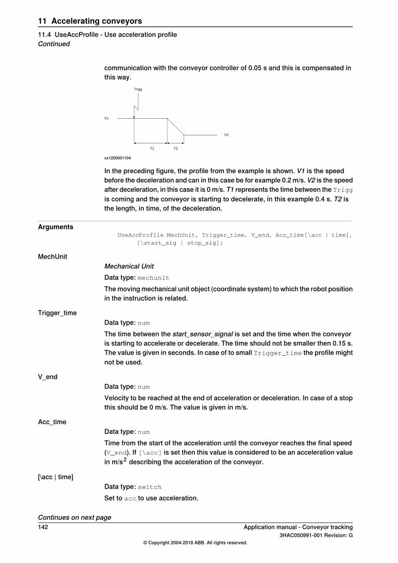
communication with the conveyor controller of 0.05 s and this is compensated inthis way.
T2T1
Trigg
V1
V2
xx1200001104
In the preceding figure, the profile from the example is shown. V1 is the speedbefore the deceleration and can in this case be for example 0.2 m/s. V2 is the speedafter deceleration, in this case it is 0 m/s. T1 represents the time between the Triggis coming and the conveyor is starting to decelerate, in this example 0.4 s. T2 isthe length, in time, of the deceleration.
ArgumentsUseAccProfile MechUnit, Trigger_time, V_end, Acc_time[\acc | time],
[\start_sig | stop_sig];
MechUnitMechanical UnitData type: mechunitThe moving mechanical unit object (coordinate system) to which the robot positionin the instruction is related.
Trigger_timeData type: numThe time between the start_sensor_signal is set and the time when the conveyoris starting to accelerate or decelerate. The time should not be smaller then 0.15 s.The value is given in seconds. In case of to small Trigger_time the profile mightnot be used.
V_endData type: numVelocity to be reached at the end of acceleration or deceleration. In case of a stopthis should be 0 m/s. The value is given in m/s.
Acc_timeData type: numTime from the start of the acceleration until the conveyor reaches the final speed(V_end). If [\acc] is set then this value is considered to be an acceleration valuein m/s2 describing the acceleration of the conveyor.
[\acc | time]Data type: switchSet to acc to use acceleration.
Continues on next page142 Application manual - Conveyor tracking
3HAC050991-001 Revision: G© Copyright 2004-2018 ABB. All rights reserved.
11 Accelerating conveyors11.4 UseAccProfile - Use acceleration profileContinued
Set to time to use acceleration time.
[\start_sig | stop_sig]Data type: switchSet to start_sig to use the signal configured as Sensor start signal to triggerthe profile. Set to stop_sig to use the signal configured as Sensor stop signal totrigger the profile.
Program executionTo get the best possible accuracy during acceleration or deceleration it is importantthat the Trigger_time is the same as the time between setting the Sensor startsignal and the time when the conveyor starts to accelerate or decelerate. The largerthe difference is between these two times the poorer accuracy will be achieved.If two profiles are configured in the system at the same time it is very importantthat the \acc option is used. This is to secure a good behavior when for examplethere is a mix between a start and a stop profile. This could happen when theconveyor for example is stopping and a start order is given so that the stop rampnever is finished.
LimitationsBefore UseAccProfile is executed, the Sensor start signal and Sensor stop signalmust be reset.
Application manual - Conveyor tracking 1433HAC050991-001 Revision: G
© Copyright 2004-2018 ABB. All rights reserved.
11 Accelerating conveyors11.4 UseAccProfile - Use acceleration profile
Continued

This page is intentionally left blank
12 Indexing conveyors12.1 Description of indexing conveyor options
Indexing conveyorsAn indexing conveyor advances in steps instead of running continuously. One stepis one index, and one or several indexes creates the work object. The conveyorbelt can have pockets or magazines for the products, which makes them perfectlyaligned for picking.There are two ways to track indexing conveyors. If the conveyor is not controlledby IRC5 then recorded profiles must be used, see Tracking indexing conveyorson page 146. If the conveyor is controlled by IRC5 the option Internal ConveyorControl should be used to get the best possible accuracy. See Indexing conveyorwith servo control (Indexing Conveyor Control) on page 159.
Application manual - Conveyor tracking 1453HAC050991-001 Revision: G
© Copyright 2004-2018 ABB. All rights reserved.
12 Indexing conveyors12.1 Description of indexing conveyor options
12.2 Tracking indexing conveyors
12.2.1 Setting up tracking for an indexing conveyor
IntroductionThis section describes how to track an indexing conveyor using the optionConveyorTracking. As the conveyor is not controlled by IRC5, is not possible to know exactlyhow the conveyor speed is changing. Instead, this method uses predicted speedchanges. The repeatability is very important for the accuracy. Therefore, this methodcannot be used if the conveyor movements are not repeatable. Then the optionIndexing Conveyor Control with the conveyor controlled by the robot controllershould be used.To get good accuracy for indexing conveyors it must be possible to predict howthe speed of the conveyor is changing. The prediction is based on a recordedprofile of the conveyor during acceleration.A new I/O signal must be defined and connected. RAPID instructions are used tohandle prediction of conveyor position during speed changes.
Setting up tracking for an indexing conveyorUse this procedure to set up tracking for an indexing conveyor.
1 Define a new I/O signal, topic I/O. See Technical reference manual - Systemparameters.
2 Connect the I/O signal to the conveyor system, topic Process. See Systemparameters on page 147.
3 Define speed filter parameter. See System parameters on page 147.4 Record the profile. See RecordProfile on page 149.5 Store the profile. See StoreProfile on page 152.6 Load and/or activate the profile for production. See LoadProfile on page153,
and ActivateProfile on page 154.
146 Application manual - Conveyor tracking3HAC050991-001 Revision: G
© Copyright 2004-2018 ABB. All rights reserved.
12 Indexing conveyors12.2.1 Setting up tracking for an indexing conveyor
12.2.2 System parameters
Topic I/OThis parameter belongs to the type Fieldbus Command in the topic I/O, forDSQC377. The corresponding filter should be set for DSQC2000, according to theConfiguring an encoder on page 56 section.
DescriptionParameter
Specifies the location of the real part of the poles in the left-half plane(in Hz). This is the break frequency for the speed filters in the DSQC377Band regulates how hard the speed is filtered. For indexing conveyorsthis parameter should be set between 10 and 15 Hz to have a good ac-curacy during stop and start.
IIRFFP
Topic ProcessThis parameter belongs to the type Conveyor systems in the topic Process.
DescriptionParameter
Name of the digital input signal to synchronize recorded profile and newindex movement. The signal must be set before start of conveyormovement. For example when a cam to move the conveyor the sensorcan be placed to be triggered 100 ms before conveyor moves.
Sensor_start_sig-nal
Application manual - Conveyor tracking 1473HAC050991-001 Revision: G
© Copyright 2004-2018 ABB. All rights reserved.
12 Indexing conveyors12.2.2 System parameters

12.2.3 Replacing the xx
IntroductionThere are two ways to use the indexing conveyor tracking functionality from RAPID.One is to use the instruction CnvGenInstr, the other to use the predefined RAPIDfunctions located in the RAPID module named Indexing_cnv.sys. The RAPIDinstructions in Indexing_cnv.sys encapsulates the functionality in CnvGenInstr
to make it easier to use. To access these RAPID instructions, load the moduleIndexing_cnv.sys from the conveyor tracking option directory, that is,\ROBOTWARE_6.XX_XXXX\options\cnv\
148 Application manual - Conveyor tracking3HAC050991-001 Revision: G
© Copyright 2004-2018 ABB. All rights reserved.
12 Indexing conveyors12.2.3 Replacing the xx
12.2.4 RecordProfile
DescriptionRecordProfile resets all profile data and records a new profile of the conveyormovement as soon as the sensor_start_signal is set.To be able to make a recording it is important that a connection to a work objectis made before the recording is started. This means that a WaitWobj instructionhas to be executed before the recording starts.
ExampleActUnit CNV1;
WaitWobj wobj_on_cnv1;
RecordProfile CNV1, 1, "index_profile";
WaitTime 0.2;
PulseDO \HIGH sensor_start_signal_DO;
SetDO STARTSTOP_CNV 1;
A profile of the conveyor is recorded as soon as the sensor_start_signal is set. Inthis example, the signal STARTSTOP_CNV starts the conveyor movement.
ArgumentsRecordProfile MechUnit, Record_duration, Profile_type
MechUnitData type: mechunitThe moving mechanical unit object (coordinate system) to which the robot positionin the instruction is related.
Record_durationDuration of speedData type: numSpecifies the duration of record in seconds. Must be between 0.1 andpos_update_time * 300.
Profile_typeType of profileData type: string
DescriptionValue
Recording is started by sensor_start_signal.index_profile
A start and stop movement can be recorded. sensor_start_signal is usedto record start movement and sensor_stop_signal is used to recordstop_movement.
start_stop_profile
Same as for start_stop_profile but the sensor_stop_signal is usedfirst.
stop_start_profile
The recording is started with sensor_stop_signal.stop_move_pro-file
Application manual - Conveyor tracking 1493HAC050991-001 Revision: G
© Copyright 2004-2018 ABB. All rights reserved.
12 Indexing conveyors12.2.4 RecordProfile
12.2.5 WaitAndRecProf
DescriptionWaitAndRecProf resets all profile data and records a new profile of the conveyormovement as soon as the sensor_start_signal is set.This instruction does the same as the instruction RecordProfile but it alsohandles the connection to a work object on the conveyor. This instruction isintended for use in PickMaster where the instruction WaitWobj is not available.
ExampleWaitAndRecProf CNV1, 1, "index_profile";
A profile of the conveyor is recorded as soon as the sensor_start_signal is set.
Program executionUse this procedure to execute the instruction WaitAndRecProf.
ArgumentsWaitAndRecProf MechUnit, Record_duration, Profile_type
MechUnitData type: mechunitThe moving mechanical unit object (coordinate system) to which the robot positionin the instruction is related.
Record_durationDuration of speedData type: numSpecifies the duration of record in seconds. Must be between 0.1 andpos_update_time * 300.
Profile_typeType of profileData type: string
DescriptionValue
Recording is started by sensor_start_signal.index_profile
A start and stop movement can be recorded. sensor_start_signal is usedto record start movement and sensor_stop_signal is used to recordstop_movement.
start_stop_profile
Same as for start_and_stop_profile but the sensor_stop_signal isused first.
stop_start_profile
The recording is started with sensor_stop_signal.stop_move_pro-file
Continues on next page150 Application manual - Conveyor tracking
3HAC050991-001 Revision: G© Copyright 2004-2018 ABB. All rights reserved.
12 Indexing conveyors12.2.5 WaitAndRecProf
Note
It is possible for the recording to fail and due to this no object gets created. Asa result, the routine WaitAndRecProf is blocked in waitwobjwith the messageWaiting for sync signal. To simulate an object, use RAPIDcommand PulseDO \PLength:=0.1,c1SoftSyncSig;. After recording theprofile, it is recommended to store the file and verify it. The first column is time,the second column is position, and the third column is speed.
Application manual - Conveyor tracking 1513HAC050991-001 Revision: G
© Copyright 2004-2018 ABB. All rights reserved.
12 Indexing conveyors12.2.5 WaitAndRecProf
Continued

12.2.6 StoreProfile
DescriptionStoreProfile activates and saves a recorded profile in a file.
ExampleActUnit CNV1;
WaitWobj wobj_on_cnv1;
RecordProfile CNV1, 1, "index_profile";
WaitTime 0.2;
PulseDO \HIGH sensor_start_signal_DO;
SetDO STARTSTOP_CNV 1;
WaitTime 2;
SetDO STARTSTOP_CNV 0;
StoreProfile CNV1, 0, "Profile.log";
A profile of the conveyor movement is recorded as soon as the sensor_start_signalis set and is stored in file profile.log.
ArgumentsStoreProfile MechUnit, Delay, Filename
MechUnitData type: mechunitThe moving mechanical unit object (coordinate system) to which the robot positionin the instruction is related.
DelayData type: numThe delay in seconds can be used to shift the record in time. It must be between0.01 and 0.1. If the value is 0 (zero) no delay is added. The delay is not saved inthe profile, it is only used for the activation. If the delay should be used togetherwith a saved profile the delay has to be specified again in the instructionLoadProfile.
FilenameData type: stringName of the file where the profile is stored.
152 Application manual - Conveyor tracking3HAC050991-001 Revision: G
© Copyright 2004-2018 ABB. All rights reserved.
12 Indexing conveyors12.2.6 StoreProfile

12.2.7 LoadProfile
DescriptionLoadProfile loads a recorded profile from a file.
ExampleLoadProfile CNV1, 0, "profile.log";
WaitTime 0.2;
PulseDO \HIGH sensor_start_signal_DO;
SetDO STARTSTOP_CNV 1;
!
! Work against the conveyor
!
SetDO STARTSTOP_CNV 0;
A saved profile of the conveyor movement is loaded and used for prediction ofconveyor movement as soon as sensor_start_signal is set. Error warningSYS_ERR_MOC_CNV_REC_FILE_UNKNOWN if the file is not found.
ArgumentsLoadProfile MechUnit, Delay, Filename
MechUnitData type: mechunitThe moving mechanical unit object (coordinate system) to which the robot positionin the instruction is related.
DelayData type: numThe delay in seconds can be used to shift the record in time. It must be between0.01 and 0.1. If the value is 0 (zero) no delay is added. The delay is not saved inthe profile, it is only used for the activation.
FilenameData type: stringName of the file where the profile is stored.
Application manual - Conveyor tracking 1533HAC050991-001 Revision: G
© Copyright 2004-2018 ABB. All rights reserved.
12 Indexing conveyors12.2.7 LoadProfile

12.2.8 ActivateProfile
DescriptionActivateProfile activates a profile that was just recorded to use it withouthaving to save it before.If the system is restarted, all unsaved records are lost. Therefore, use LoadProfileafter restarts.Do not use ActivateProfile after LoadProfile.
ExampleActivateProfile CNV1, 0;
WaitTime 0.2;
PulseDO \HIGH sensor_start_signal_DO;
SetDO STARTSTOP_CNV 1;
!
! Work against the conveyor
!
SetDO STARTSTOP_CNV 0;
A profile of the conveyor is activated and used for prediction of conveyor movementas soon as the sensor_start_signal is set. Error warningSYS_ERR_MOC_CNV_REC_NOT_READY if record not finished.
ArgumentsActivateProfile MechUnit, Delay
MechUnitData type: mechunitThe moving mechanical unit object (coordinate system) to which the robot positionin the instruction is related.
DelayData type: numThe delay in seconds can be used to shift the record in time. It must be between0.01 and 0.1. If the value is 0 (zero) no delay is added.
154 Application manual - Conveyor tracking3HAC050991-001 Revision: G
© Copyright 2004-2018 ABB. All rights reserved.
12 Indexing conveyors12.2.8 ActivateProfile

12.2.9 DeactProfile
DescriptionDeactProfile deactivates a profile.
ExampleDeactProfile CNV1;
A profile of the conveyor movement is deactivated and no longer used for predictionof conveyor movement.
ArgumentsDeactProfile MechUnit
MechUnitData type: mechunitThe moving mechanical unit object (coordinate system) to which the robot positionin the instruction is related.
Application manual - Conveyor tracking 1553HAC050991-001 Revision: G
© Copyright 2004-2018 ABB. All rights reserved.
12 Indexing conveyors12.2.9 DeactProfile

12.2.10 CnvGenInstr
DescriptionCnvGenInstr sends a command to the conveyor process attached to the conveyormechanical unit.
ExampleCnvGenIstr CNV1, CNV_ACTIV_REC, mycnvdata;
The controller will activate the record.
ArgumentsCnvGenInstr MechUnit, cnvcmd, Data
MechUnitData type: mechunitThe moving mechanical unit object (coordinate system) to which the robot positionin the instruction is related.
cnvcmdCommandData type: numList of possible commands:
• CNV_START_REC• CNV_STOP_REC• CNV_ACTIV_REC• CNV_USE_FREC• CNV_RESET_ALPROF• CNV_DEACT_PROF• CNV_STORE_PROF
DataDataData type: cnvgendataThis structure is used to send num or string as parameters for different commands.
Program executionAll commands must be sent at least 0.2 seconds before start of conveyor movement.
More examples
Example1VAR cnvgendata mycnvdata:=[0,0,0,0,"",""];
CnvGenInstr CNV2,CNV_START_REC,mycnvdata;
mycnvdata.value1:=1;
In this example, data.value1 specifies the duration of recording in seconds. Thisvalue must be between 0.1 and pos_update_time * 300.
Continues on next page156 Application manual - Conveyor tracking
3HAC050991-001 Revision: G© Copyright 2004-2018 ABB. All rights reserved.
12 Indexing conveyors12.2.10 CnvGenInstr

Example 2CnvGenInstr CNV2,CNV_STOP_REC,mycnvdata;
This example can be used if CNV_START_REC has been sent with duration 0.
Example 3CnvGenInstr CNV2,CNV_ACTIV_REC,mycnvdata;
mycnvdata.value1:=0;
In this example, data.value1 specifies a delay added to record in seconds. Thisvalue must be between 0.01 and 0.1 seconds.If value1=0 default value: then signal delay is used. Ready for use of profile onnext index movement. Error warning SYS_ERR_MOC_CNV_REC_NOT_READY if recordnot finished.
Example 4CnvGenInstr CNV2,CNV_USE_FREC,mycnvdata;
mycnvdata.string1:="myprofile": string1 must contain the name of the file whereto read the recorded profile.The file must have been created by the command CNV_STORE_PROF. Ready foruse of profile on next index movement.Error warning SYS_ERR_MOC_CNV_REC_FILE_UNKNOWN if record file not found.
Example 5CnvGenInstr CNV2,CNV_RESET_ALPROF,mycnvdata;
Reset all profile data, ready for a new START_REC.
Example 6CnvGenInstr CNV2,CNV_DEACT_PROF,mycnvdata;
Stop using profile.
Example 7CnvGenInstr CNV2,CNV_STORE_PROF,mycnvdata;
mycnvdata.string1:="myprofile";string1 must contain the name of the file to storethe profile.
LimitationsAs access to files can take a lot of time it is recommended not to useCNV_USE_FREC and CNV_STORE_PROF while robot is moving.Repeatability error between record and real cycles must be less than 120 ms. Adelay between sensor_start_signal and conveyor movement must not vary morethan 120 ms.
Error handlingNo error handling for this instruction. In case of emergency stop of robot or conveyorthe command CNV_DEACT_PROF should be used before restarting the robot.
SyntaxCnvGenInstr
[ MechUnit ':=']< var of mechanical unit > ';'
[ Command ':=']< expression (IN) of num> ';'
Continues on next pageApplication manual - Conveyor tracking 1573HAC050991-001 Revision: G
© Copyright 2004-2018 ABB. All rights reserved.
12 Indexing conveyors12.2.10 CnvGenInstr
Continued

[ Data ':=']< var of cnvgendata> ';'
158 Application manual - Conveyor tracking3HAC050991-001 Revision: G
© Copyright 2004-2018 ABB. All rights reserved.
12 Indexing conveyors12.2.10 CnvGenInstrContinued

12.3 Indexing conveyor with servo control (Indexing Conveyor Control)
12.3.1 Introduction to indexing conveyors with servo control
Description of Indexing Conveyor ControlThe option Indexing Conveyor Control includes RAPID instructions and one RAPIDdata type. A typical installation includes an infeed conveyor transporting theproducts in a row at high speed to the indexing conveyor. A photo eye (sensor)mounted on the infeeder detects products and sends a trig signal to the IRC5controller. The controller starts the indexing movement after a specified time, thatis, when the product has entered the pocket on the indexing conveyor. TheFlexPicker picks the products from the indexing conveyor, even during indexingmovement, and puts them in a box on the output conveyor.The IRC5 controls the FlexPicker and the indexing conveyor. The output conveyorand the infeeder have their own drive systems.Conveyor tracking will be used both on the indexing conveyor and the outputconveyor, but no encoder and encoder interface is needed on the indexing conveyorsince the position and speed are known as a part of the path planning in the IRC5controller.
Continues on next pageApplication manual - Conveyor tracking 1593HAC050991-001 Revision: G
© Copyright 2004-2018 ABB. All rights reserved.
12 Indexing conveyors12.3.1 Introduction to indexing conveyors with servo control

Schematic overview
xx1000001425
Robot with gripperA
Output conveyor with empty cartons, for example from carton erectorB
Robot picks products from indexing conveyor and places in cartonsC
Full cartons, for example to carton closerD
Indexing conveyor with pocketsE
Photo eyeF
Product infeederG
TerminologyIn context of controlling and moving the conveyor this is referred to as M7 in thisdocument.In context of tracking the conveyor, it is referred to as CNV1. Hence, the conveyorwill be configured as two different mechanical units, M7 and CNV1.Indexing mode is when the system listens (or waits) for a signal from the sensorthat a product is available.In indexing mode it is not possible to jog or use Move instructions. To disableindexing mode, execute IndCnvReset or move the program pointer to the routineMain (PP to Main).
Continues on next page160 Application manual - Conveyor tracking
3HAC050991-001 Revision: G© Copyright 2004-2018 ABB. All rights reserved.
12 Indexing conveyors12.3.1 Introduction to indexing conveyors with servo controlContinued

LimitationsWhen using the option Indexing Conveyor Control, up to two indexing conveyorsand two conventional (non-indexing) conveyors with encoder boards can be usedper controller. Up to two IRB 360 robots can be configured in a MultiMove system.To be able to have two robots working on the same indexing conveyor, the optionsAdvanced Quetracking or PickMaster 3 must be used.
Application manual - Conveyor tracking 1613HAC050991-001 Revision: G
© Copyright 2004-2018 ABB. All rights reserved.
12 Indexing conveyors12.3.1 Introduction to indexing conveyors with servo control
Continued
12.3.2 Setting up a servo controlled indexing conveyor
Installing the additional axis for servo controlFor the option Indexing Conveyor Control, install the indexing conveyor as an IRC5additional axis. SeeApplicationmanual - Additional axes and stand alone controller.When installed, the indexing conveyor should be running as an IRC5 additionalaxis.
Installing the softwareThe conveyor tracking RAPID instructions, data types, and mechanical unit CNV1are specified in the key string and do not need to be installed. If the system consistsof more than one conveyor, three more files must be installed per conveyor. Thefiles to install are stored on the controller.The second conveyor to install is called CNV2 and the Motion configuration file isnamed cnv2_moc.cfg. The other two files to install for internally controlled conveyorsare cnvint2_prc.cfg and cnvint2_eio.cfg.
162 Application manual - Conveyor tracking3HAC050991-001 Revision: G
© Copyright 2004-2018 ABB. All rights reserved.
12 Indexing conveyors12.3.2 Setting up a servo controlled indexing conveyor
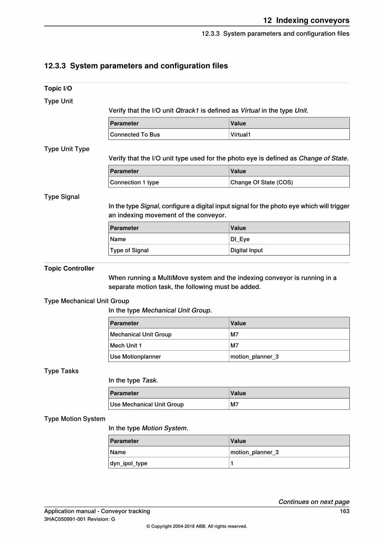
12.3.3 System parameters and configuration files
Topic I/O
Type UnitVerify that the I/O unit Qtrack1 is defined as Virtual in the type Unit.
ValueParameter
Virtual1Connected To Bus
Type Unit TypeVerify that the I/O unit type used for the photo eye is defined as Change of State.
ValueParameter
Change Of State (COS)Connection 1 type
Type SignalIn the type Signal, configure a digital input signal for the photo eye which will triggeran indexing movement of the conveyor.
ValueParameter
DI_EyeName
Digital InputType of Signal
Topic ControllerWhen running a MultiMove system and the indexing conveyor is running in aseparate motion task, the following must be added.
Type Mechanical Unit GroupIn the type Mechanical Unit Group.
ValueParameter
M7Mechanical Unit Group
M7Mech Unit 1
motion_planner_3Use Motionplanner
Type TasksIn the type Task.
ValueParameter
M7Use Mechanical Unit Group
Type Motion SystemIn the type Motion System.
ValueParameter
motion_planner_3Name
1dyn_ipol_type
Continues on next pageApplication manual - Conveyor tracking 1633HAC050991-001 Revision: G
© Copyright 2004-2018 ABB. All rights reserved.
12 Indexing conveyors12.3.3 System parameters and configuration files
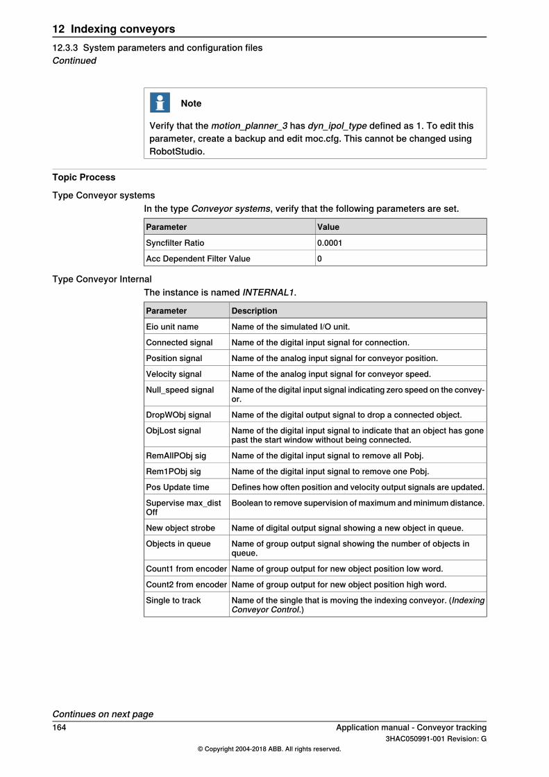
Note
Verify that the motion_planner_3 has dyn_ipol_type defined as 1. To edit thisparameter, create a backup and edit moc.cfg. This cannot be changed usingRobotStudio.
Topic Process
Type Conveyor systemsIn the type Conveyor systems, verify that the following parameters are set.
ValueParameter
0.0001Syncfilter Ratio
0Acc Dependent Filter Value
Type Conveyor InternalThe instance is named INTERNAL1.
DescriptionParameter
Name of the simulated I/O unit.Eio unit name
Name of the digital input signal for connection.Connected signal
Name of the analog input signal for conveyor position.Position signal
Name of the analog input signal for conveyor speed.Velocity signal
Name of the digital input signal indicating zero speed on the convey-or.
Null_speed signal
Name of the digital output signal to drop a connected object.DropWObj signal
Name of the digital input signal to indicate that an object has gonepast the start window without being connected.
ObjLost signal
Name of the digital input signal to remove all Pobj.RemAllPObj sig
Name of the digital input signal to remove one Pobj.Rem1PObj sig
Defines how often position and velocity output signals are updated.Pos Update time
Boolean to remove supervision of maximum and minimum distance.Supervise max_distOff
Name of digital output signal showing a new object in queue.New object strobe
Name of group output signal showing the number of objects inqueue.
Objects in queue
Name of group output for new object position low word.Count1 from encoder
Name of group output for new object position high word.Count2 from encoder
Name of the single that is moving the indexing conveyor. (IndexingConveyor Control.)
Single to track
Continues on next page164 Application manual - Conveyor tracking
3HAC050991-001 Revision: G© Copyright 2004-2018 ABB. All rights reserved.
12 Indexing conveyors12.3.3 System parameters and configuration filesContinued

Topic Motion
Type ArmIn the type Arm, enable Independent Joint and add joint limits.
ValueParameter
OnIndependent Joint
2E+07Independent Upper Joint Bound
-2E+07Independent Lower Joint Bound
Type Single TypeIn the typeSingle Type, the parameterPocket size defines the distance the conveyorwill move when triggered by the photo eye (the size of one pocket), see the followinggraphic. It is very important for conveyor tracking accuracy that the pocket size isgiven correctly. Use measuring tape and measure at least ten pockets to have aan average for one pocket.Time before indexing move defines the time from the photo eye is triggered untilthe conveyor movement starts. The recommended value is 0.3 (300 ms). Dependingon the robot payload and deceleration distance, this value can be decreased (mightbe needed to increase for some applications). If it is important to use a value assmall as possible, see Minimizing trigger time on page 178.
ValueParameter
FREE_ROTMechanics
YesIndexing move
0.3Time before indexing move
0.05Pocket size
xx1200001105
Pocket sizeA
Continues on next pageApplication manual - Conveyor tracking 1653HAC050991-001 Revision: G
© Copyright 2004-2018 ABB. All rights reserved.
12 Indexing conveyors12.3.3 System parameters and configuration files
Continued

Type TransmissionThe transmission must be represented by two integer parameters, TransmissionGear High and Transmission Gear Low. This is needed to avoid loosing accuracyafter a very big number of indexing movements. These parameters are computedin a way that makes it possible for the controller to move the indexing conveyorexactly one pocket instead of for example 50 mm which could be the measuredpocket size.
A B
C
D
E
xx1200001106
PocketsA
MotorB
GearboxC
Gear wheel teethD
Belt teethE
See the following example for the calculation of the parameters Transmission GearHigh, Transmission Gear Low, and Transmission Gear Ratio. With this setup, theparameter Rotating Move must be set.Calculation example:D = Number of gear wheel teethA = Number of pocketsTransmission Gear Low = D * A = 20 * 36 = 720G = Gear box ratioE = Number of belt teethTransmission Gear High = G * E * 360 = 10 * 108 * 360 = 388800Transmission Gear Ratio = Transmission Gear High / Transmission Gear Low =388800 / 720 = 540 / 1 = 540In this example we use the gear box ratio 10, this means 10 motor revolutionscorrespond to one gear wheel revolution. The Transmission Gear High /Transmission Gear Low ratio can be given as 388800 / 720 but 540 / 1 is easier tocomprehend.
ValueParameter
YESRotating move
Continues on next page166 Application manual - Conveyor tracking
3HAC050991-001 Revision: G© Copyright 2004-2018 ABB. All rights reserved.
12 Indexing conveyors12.3.3 System parameters and configuration filesContinued

ValueParameter
540 (from example)Transmission Gear Ratio
540 (from example)Transmission Gear High
1 (from example)Transmission Gear Low
Type Acceleration DataFor an indexing conveyor the acceleration data is given in m/s2 even though theparameter Rotating Move is set. The indexing movement will be a symmetrictriangular motion profile.If different values are given for acceleration and deceleration, the smallest valuewill be used when creating the motion path.To avoid vibrations and overload of the mechanical structure, the values foracceleration and deceleration should not be set higher than the robot capacity atthe given payload.
ValueParameter
25Nominal Acceleration
25Nominal Deceleration
Application manual - Conveyor tracking 1673HAC050991-001 Revision: G
© Copyright 2004-2018 ABB. All rights reserved.
12 Indexing conveyors12.3.3 System parameters and configuration files
Continued

12.3.4 Testing the indexing conveyor setup
TestingCreate a RAPID program using the code from the example below. Speed andacceleration are given in mm/s respectively mm/s2 . To avoid vibrations and overloadof the mechanical structure, the values for acceleration and deceleration shouldnot be set higher than the robot capacity at the given payload.In this example an indexing movement will be performed each time the digital inputsignal DI_Eye is triggered.
RAPID exampleMODULE MainModule
VAR indcnvdata indcnvdata1:=[0,0,0,0,0,0,0];
PROC main()
indcnvdata1.speed := 2000;
indcnvdata1.acceleration := 25000;
indcnvdata1.productsperpick := 6;
indcnvdata1.productsperindex := 1;
ActUnit M7;
IndCnvInit M7, DI_Eye, indcnvdata1;
IndCnvEnable M7;
WHILE TRUE DO
WaitTime 1;
ENDWHILE
ENDPROC
ENDMODULE
168 Application manual - Conveyor tracking3HAC050991-001 Revision: G
© Copyright 2004-2018 ABB. All rights reserved.
12 Indexing conveyors12.3.4 Testing the indexing conveyor setup
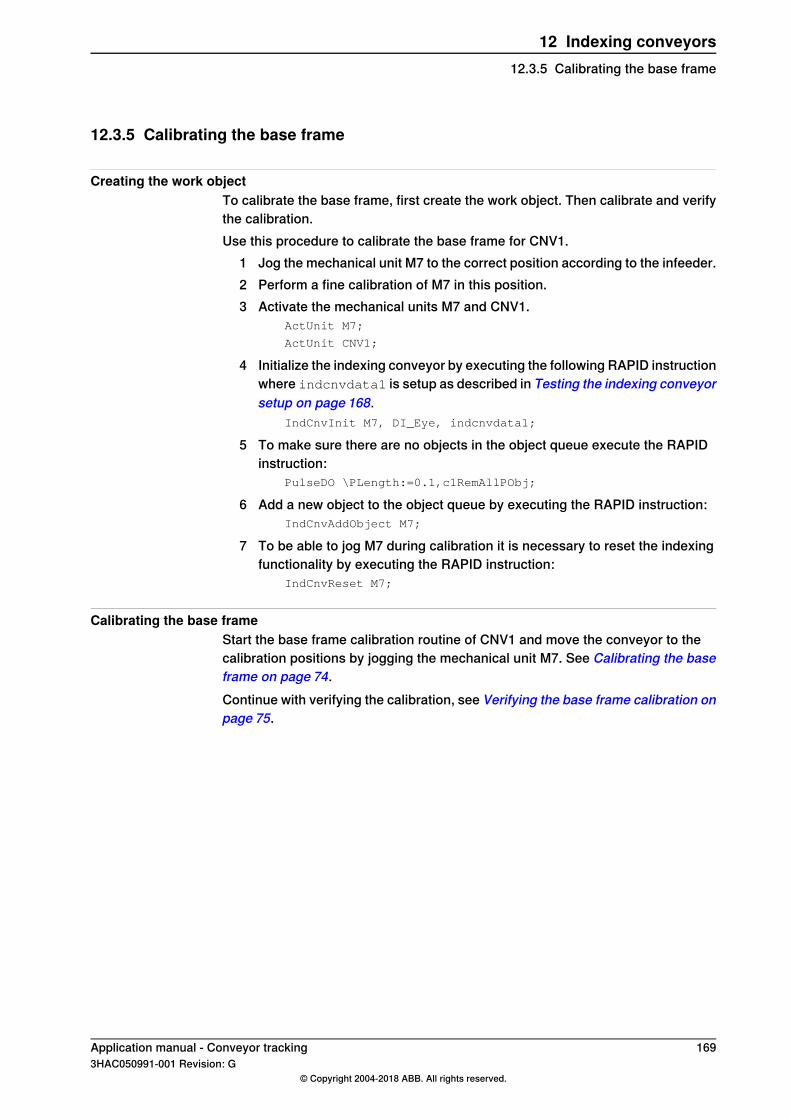
12.3.5 Calibrating the base frame
Creating the work objectTo calibrate the base frame, first create the work object. Then calibrate and verifythe calibration.Use this procedure to calibrate the base frame for CNV1.
1 Jog the mechanical unit M7 to the correct position according to the infeeder.2 Perform a fine calibration of M7 in this position.3 Activate the mechanical units M7 and CNV1.
ActUnit M7;
ActUnit CNV1;
4 Initialize the indexing conveyor by executing the following RAPID instructionwhere indcnvdata1 is setup as described in Testing the indexing conveyorsetup on page 168.
IndCnvInit M7, DI_Eye, indcnvdata1;
5 To make sure there are no objects in the object queue execute the RAPIDinstruction:
PulseDO \PLength:=0.1,c1RemAllPObj;
6 Add a new object to the object queue by executing the RAPID instruction:IndCnvAddObject M7;
7 To be able to jog M7 during calibration it is necessary to reset the indexingfunctionality by executing the RAPID instruction:
IndCnvReset M7;
Calibrating the base frameStart the base frame calibration routine of CNV1 and move the conveyor to thecalibration positions by jogging the mechanical unit M7. See Calibrating the baseframe on page 74.Continue with verifying the calibration, see Verifying the base frame calibration onpage 75.
Application manual - Conveyor tracking 1693HAC050991-001 Revision: G
© Copyright 2004-2018 ABB. All rights reserved.
12 Indexing conveyors12.3.5 Calibrating the base frame

12.3.6 indcnvdata
DescriptionThe data type indcnvdata contains information about the indexing movementand the number of pockets that the work object holds.
ExampleVAR indcnvdata indcnvdata1:=[0,0,0,0,0,0,0];
indcnvdata1.speed:= 2000;
indcnvdata1.acceleration := 25000;
indcnvdata1.productsperpick := 6;
indcnvdata1.productsperindex := 1;
indcnvdata1.accuracytuning := 0;
Components
speedConveyor speed in mm/s. Normally this parameter is set to a high value to createa motion profile that is triangular.
accelerationConveyor acceleration in mm/s2 . This value cannot be higher than what isconfigured in Acceleration Data, see Type Acceleration Data on page 167.To avoid vibrations and overload of the mechanical structure, the values foracceleration and deceleration should not be set higher than the robot capacity atthe given payload.
productsperpickThe number of pockets that offsets each work object. If there is one product ineach pocket this parameter defines how many products the robot will pick in eachrobot cycle.
productsperindexUse this parameter to set how many products that should enter each pocket beforeexecuting an indexing movement.
accuracytuningThis parameter can be used to tune the synchronization between robot and indexingconveyor and requires a high speed camera. The tuning value is default 0 and canbe adjusted +-10ms.
170 Application manual - Conveyor tracking3HAC050991-001 Revision: G
© Copyright 2004-2018 ABB. All rights reserved.
12 Indexing conveyors12.3.6 indcnvdata
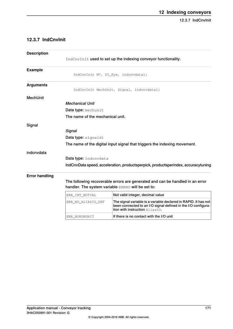
12.3.7 IndCnvInit
DescriptionIndCnvInit used to set up the indexing conveyor functionality.
ExampleIndCnvInit M7, DI_Eye, indcnvdata1;
ArgumentsIndCnvInit MechUnit, Signal, indcnvdata1;
MechUnitMechanical UnitData type: mechunitThe name of the mechanical unit.
SignalSignalData type: signaldiThe name of the digital input signal that triggers the indexing movement.
indcnvdataData type: indcnvdataIndCnvData speed, acceleration, productsperpick, productsperindex, accuracytuning
Error handlingThe following recoverable errors are generated and can be handled in an errorhandler. The system variable ERRNO will be set to:
Not valid integer, decimal valueERR_INT_NOTVAL
The signal variable is a variable declared in RAPID. It has notbeen connected to an I/O signal defined in the I/O configura-tion with instruction AliasIO.
ERR_NO_ALIASIO_DEF
If there is no contact with the I/O unitERR_NORUNUNIT
Application manual - Conveyor tracking 1713HAC050991-001 Revision: G
© Copyright 2004-2018 ABB. All rights reserved.
12 Indexing conveyors12.3.7 IndCnvInit

12.3.8 IndCnvEnable and IndCnvDisable
DescriptionIndCnvEnable is used to set the system in indexing mode. An indexing movementwill be executed when the signal is triggered (indexing mode).IndCnvDisable is used to stop listening to the digital input signal. No indexingmovement will be performed even if the signal is triggered.
Note
It is not possible to jog or run Move instructions on the indexing conveyor untila IndCnvReset instruction has been executed.
ExampleIndCnvEnable M7;
IndCnvDisable M7;
ArgumentsIndCnvEnable MechUnit;
IndCnvDisable MechUnit;
MechUnitMechanical UnitData type: mechunitThe name of the mechanical unit.
Error handlingThe following recoverable errors are generated and can be handled in an errorhandler. The system variable ERRNO will be set to:
An instruction requires execution of IndCnvInit before it isexecuted.
ERR_INDCNV_ORDER
172 Application manual - Conveyor tracking3HAC050991-001 Revision: G
© Copyright 2004-2018 ABB. All rights reserved.
12 Indexing conveyors12.3.8 IndCnvEnable and IndCnvDisable

12.3.9 IndCnvReset
DescriptionIndCnvReset ends indexing mode and sets the system to normal mode whichmakes it possible to jog and run Move instructions.
ExampleIndCnvReset M7;
ArgumentsIndCnvReset MechUnit;
MechUnitMechanical UnitData type: mechunitThe name of the mechanical unit.
Application manual - Conveyor tracking 1733HAC050991-001 Revision: G
© Copyright 2004-2018 ABB. All rights reserved.
12 Indexing conveyors12.3.9 IndCnvReset

12.3.10 IndCnvAddObject
DescriptionTo manually add an object to the object queue, the RAPID instructionIndCnvAddObject can be executed.
ExampleIndCnvAddObject M7;
ArgumentsIndCnvAddObject MechUnit;
MechUnitMechanical UnitData type: mechunitThe name of the mechanical unit.
174 Application manual - Conveyor tracking3HAC050991-001 Revision: G
© Copyright 2004-2018 ABB. All rights reserved.
12 Indexing conveyors12.3.10 IndCnvAddObject

12.3.11 RAPID programming example
DescriptionIn this example an IRB 360 is picking a batch of products from an indexing conveyor(CNV1) and placing the products on the outfeed conveyor (CNV2). The outfeedconveyor is not controlled by IRC5.
Example codeMODULE MainModule
TASK PERS wobjdata wobj1:= [FALSE,FALSE,"CNV1",[[0,0,0],[1,0,0,0]],[[0,0,0],[1,0,0,0]]];
TASK PERS wobjdata wobj2:= [FALSE,FALSE,"CNV2",[[0,0,0],[1,0,0,0]],[[0,0,0],[1,0,0,0]]];
CONST robtarget WaitPos:= [[-129.82,1.57,-924.52],[0,0.999848,-0.0174063,0],[0,0,0,0],[0,9E+09,9E+09,9E+09,0,0]];
CONST robtarget Cnv1_Above:= [[24.81,40.73,34.42],[0.000115829,-0.753048,0.657965,-0.000112099],[0,1,0,0],[171.015,9E+09,9E +09,9E+09,277.57,400]];
CONST robtarget Cnv1_Below:= [[24.81,40.73,-9.77],[0.000115827,-0.75306,0.657952,-0.000112101],[0,1,0,0],[171.015,9E+09,9E +09,9E+09,277.57,400]];
CONST robtarget Cnv2_Above:= [[-23.46,-1.68,201.85],[1.72038E-05,0.997874,0.0651587,-0.000988565],[0,0,0,0],[158.015,9E+09,9E +09,9E+09,277.57,0]];
CONST robtarget Cnv2_Below:= [[-23.46,-1.68,55.28],[1.72335E-05,0.997876,0.0651288,-0.000988564],[0,0,0,0],[158.015,9E+09,9E +09,9E+09,277.57,0]];
PERS tooldata Tool_2:=[TRUE,[[0,0,56.5],[1,0,0,0]],[2,[0,0,26],[1,0,0,0],0,0,0.0016]];
VAR triggdata EaciPick;
VAR triggdata EaciPlace;
VAR speeddata speed_eaci;
VAR indcnvdata indcnvdata1:=[0,0,0,0,0,0,0];
VAR num prod_cnt;
CONST stoppointdatastoppoint_eaci:=[3,FALSE,[0,0,0,0],0,0.035,"",0,0];
PROC main()
indcnvdata1.speed := 2000;
indcnvdata1.acceleration := 25000;
indcnvdata1.productsperpick := 6;
indcnvdata1.productsperindex := 1;
prod_cnt := 0;
speed_eaci.v_tcp:= 5000;
speed_eaci.v_ori:= 10000;
! Activate mechanical units
ActUnit M7;
ActUnit CNV1;
Continues on next pageApplication manual - Conveyor tracking 1753HAC050991-001 Revision: G
© Copyright 2004-2018 ABB. All rights reserved.
12 Indexing conveyors12.3.11 RAPID programming example

ActUnit CNV2;
! Remove from queue and drop objects
PulseDO \PLength:=0.1,c1RemAllPObj;
PulseDO \PLength:=0.1,c2RemAllPObj;
DropWObj wobj1;
IF c2Connected = 1 THEN
DropWObj wobj2;
ENDIF
! Set up pick and place trigg data
TriggEquip EaciPick, 2, 0.05 \DOp:=EaciSuck, 1;
TriggEquip EaciPlace, 2, 0.05 \DOp:=EaciSuck, 0;
! Set indexing conveyor CNV1 in indexing mode and start listeningto the photo eye signals
IndCnvInit M7, DI_Eye, indcnvdata1;IndCnvEnable M7;
! Go to init position
MoveL WaitPos, v1000, fine, Tool_2;
WHILE TRUE DO
! CNV1 Pick
WaitWObj wobj1\RelDist:=300;
MoveL Cnv1_Above, speed_eaci, z20, Tool_2\WObj:=wobj1;
TriggL Cnv1_Below, speed_eaci, EaciPick,z1\Inpos:=stoppoint_eaci, Tool_2\WObj:=wobj1;
MoveL Cnv1_Above, speed_eaci, z20, Tool_2\WObj:=wobj1;
IF prod_cnt >= 1 THEN
DropWObj wobj2;
ENDIF
! CNV2 Place
WaitWObj wobj2\RelDist:=50;
MoveL Cnv2_Above, speed_eaci, z20, Tool_2\WObj:=wobj2;
TriggL Cnv2_Below, speed_eaci, EaciPlace,z1\Inpos:=stoppoint_eaci, Tool_2\WObj:=wobj2;
MoveL Cnv2_Above, speed_eaci, z20, Tool_2\WObj:=wobj2;
prod_cnt := prod_cnt + 1;
TPErase;
TPWrite " Number of products: "\Num:=prod_cnt;
DropWObj wobj1;
ENDWHILE
! Move program pointer to the instructions below to enable e.g.jogging
! Stop listening to the photo eye signals
IndCnvDisable M7;
Continues on next page176 Application manual - Conveyor tracking
3HAC050991-001 Revision: G© Copyright 2004-2018 ABB. All rights reserved.
12 Indexing conveyors12.3.11 RAPID programming exampleContinued

! Set indexing conveyor in normal mode
IndCnvReset M7;
ENDPROC
ENDMODULE
Application manual - Conveyor tracking 1773HAC050991-001 Revision: G
© Copyright 2004-2018 ABB. All rights reserved.
12 Indexing conveyors12.3.11 RAPID programming example
Continued

12.3.12 Minimizing trigger time
Trigger timeIf the parameter Time before indexingmove is set too short, the error 50423 IndCnvTime before indexing move too low can occur.To minimize the time between the trigger from the photo eye and start of theconveyor movement, follow the description below:
1 Set Time before indexing move to a high value, for example 0.4 s.2 If trigger time is critical there is a chance to reduce the time by changing the
parameters as suggested in Possible solutions on page 178.3 Run the full application with the robot coordinated to CNV1 and with full robot
payload.4 Run the service routine IndCnvOptimalTimeBefore to get a proposed
optimal time before.5 Update Time before indexing move to match the value proposed by the
service routine.There is a risk that the value suggested by the service routineIndCnvOptimalTimeBefore is too small so some extra 10 ms margin might beneeded.
Possible solutionsChange the following parameters in the type Motion Planner.
ValueParameter
0.3333Dynamic Resolution
0.3333Path Resolution
0.032256Queue Time
0.016128Group Queue Time
Possible limitationsIf the error 50082 Deceleration limit occurs, return to the original setting of QueueTime (which is 0.064512), in the type Motion Planner (topic Motion).If the error 50226 Motor reference error occurs, return to the original setting ofGroup Queue Time (which is 0.032256), in the type Motion Planner (topic Motion).
178 Application manual - Conveyor tracking3HAC050991-001 Revision: G
© Copyright 2004-2018 ABB. All rights reserved.
12 Indexing conveyors12.3.12 Minimizing trigger time
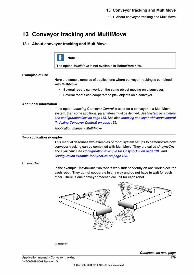
13 Conveyor tracking and MultiMove13.1 About conveyor tracking and MultiMove
Note
The option MultiMove is not available in RobotWare 5.60.
Examples of useHere are some examples of applications where conveyor tracking is combinedwith MultiMove:
• Several robots can work on the same object moving on a conveyor.• Several robots can cooperate to pick objects on a conveyor.
Additional informationIf the option Indexing Conveyor Control is used for a conveyor in a MultiMovesystem, then some additional parameters must be defined. See System parametersand configuration files on page163. See also Indexing conveyor with servo control(Indexing Conveyor Control) on page 159.Application manual - MultiMove
Two application examplesThis manual describes two examples of robot system setups to demonstrate howconveyor tracking can be combined with MultiMove. They are called UnsyncCnvand SyncCnv. See Configuration example for UnsyncCnv on page 181, andConfiguration example for SyncCnv on page 183.
UnsyncCnvIn the example UnsyncCnv, two robots work independently on one work piece foreach robot. They do not cooperate in any way and do not have to wait for eachother. There is one conveyor mechanical unit for each robot.
xx1200001107
Continues on next pageApplication manual - Conveyor tracking 1793HAC050991-001 Revision: G
© Copyright 2004-2018 ABB. All rights reserved.
13 Conveyor tracking and MultiMove13.1 About conveyor tracking and MultiMove

SyncCnvIn the example SyncCnv, two robots arc weld on the same work piece. The workobject is moved by a conveyor. One conveyor mechanical unit is used in a separatemotion planner.
xx1200001108
180 Application manual - Conveyor tracking3HAC050991-001 Revision: G
© Copyright 2004-2018 ABB. All rights reserved.
13 Conveyor tracking and MultiMove13.1 About conveyor tracking and MultiMoveContinued

13.2 Configuration example for UnsyncCnv
About this exampleThis section describes how to configure the example UnsyncCnv, with twoindependent robots. The robots are handled by one task each.
Configuration
Task
Use Mechanical UnitGroup
MotionTaskTypeTask
rob1YesNORMALT_ROB1
rob2YesNORMALT_ROB2
Mechanical Unit Group
Use Motion PlannerMech Unit 1RobotName
motion_planner_1CNV1ROB_1rob1
motion_planner_2CNV2ROB_2rob2
Motion Planner
Name
motion_planner_1
motion_planner_2
Mechanical Unit
Use Brake RelayDeactivationForbidden
Activate at Star-tup
Allow Move ofUser Frame
Name
NoYesNoROB_1
NoYesNoROB_2
rob1_brakeNoNoYesCNV1
rob2_brakeNoNoYesCNV2
Continues on next pageApplication manual - Conveyor tracking 1813HAC050991-001 Revision: G
© Copyright 2004-2018 ABB. All rights reserved.
13 Conveyor tracking and MultiMove13.2 Configuration example for UnsyncCnv

Illustration
xx1200001109
182 Application manual - Conveyor tracking3HAC050991-001 Revision: G
© Copyright 2004-2018 ABB. All rights reserved.
13 Conveyor tracking and MultiMove13.2 Configuration example for UnsyncCnvContinued
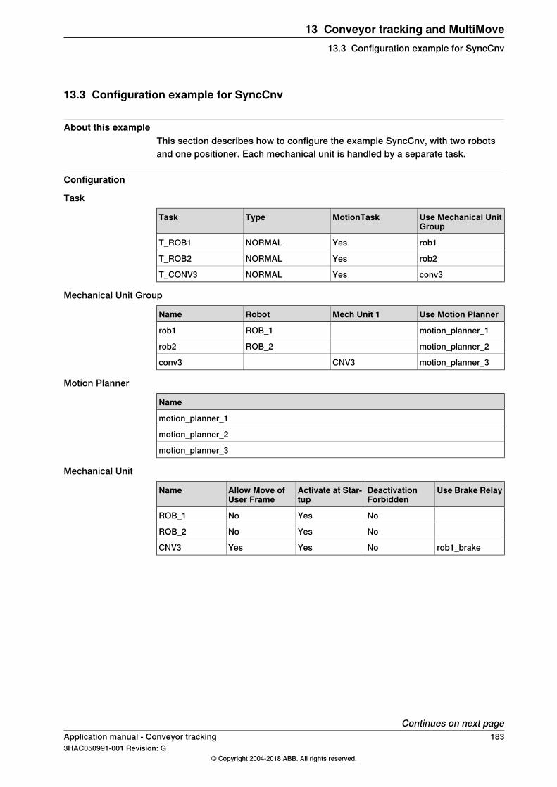
13.3 Configuration example for SyncCnv
About this exampleThis section describes how to configure the example SyncCnv, with two robotsand one positioner. Each mechanical unit is handled by a separate task.
Configuration
Task
Use Mechanical UnitGroup
MotionTaskTypeTask
rob1YesNORMALT_ROB1
rob2YesNORMALT_ROB2
conv3YesNORMALT_CONV3
Mechanical Unit Group
Use Motion PlannerMech Unit 1RobotName
motion_planner_1ROB_1rob1
motion_planner_2ROB_2rob2
motion_planner_3CNV3conv3
Motion Planner
Name
motion_planner_1
motion_planner_2
motion_planner_3
Mechanical Unit
Use Brake RelayDeactivationForbidden
Activate at Star-tup
Allow Move ofUser Frame
Name
NoYesNoROB_1
NoYesNoROB_2
rob1_brakeNoYesYesCNV3
Continues on next pageApplication manual - Conveyor tracking 1833HAC050991-001 Revision: G
© Copyright 2004-2018 ABB. All rights reserved.
13 Conveyor tracking and MultiMove13.3 Configuration example for SyncCnv

Illustration
xx1200001110
Calibration overviewFor unsynchronized movements each conveyor must be calibrated with its motiongroup robot (after the base calibration of the robot):
• Cnv1 with Robot_1• Cnv2 with Robot_2
For synchronized movements Cnv3 is calibrated with one robot only: Robot_1.
184 Application manual - Conveyor tracking3HAC050991-001 Revision: G
© Copyright 2004-2018 ABB. All rights reserved.
13 Conveyor tracking and MultiMove13.3 Configuration example for SyncCnvContinued

13.4 Tasks and programming techniques
Introduction to tasksEach task program can handle the movements for one robot and up to 6 additionalaxes. Several tasks can be used, each containing a program quite similar to theprogram of the main task in a single robot application. For more information abouttasks, see Multitasking in Application manual - Controller software IRC5.
One task program per robotEach task program can only handle one TCP. This means that you must have onetask for each robot.
Conveyor in separate tasksConveyors that move a work object can be handled by the same task program asone of the robots for un-synchronized movements. For synchronized movementswhere the conveyor should be able to move independently of the robots, it is bestto have a separate task program for the conveyor.
Modifying positionsWhen modifying positions it is not possible to just stop the conveyor and modifythe position. If this is done, there will be an offset in the position that correspondsto the length of the conveyor movement. This is since the conveyor and the robotsbelong to different mechanical unit groups, see Configuration example for SyncCnvon page 183, and the position of the conveyor is not known to the robots at thispoint.To be able to modify positions, the conveyor must belong to the same mechanicalunit group as the robot. This is done by creating "fake" conveyors that are onlyused for modifying positions.
ExampleBelow there is a configuration example for topic System. Conveyors CNV1 andCNV2 are "fake" conveyors, and conveyor CNV3 is the real conveyor.Task:
Use Mechanical UnitGroup
MotionTaskTypeTask
ROB1YesNORMALT_ROB1
ROB2YesNORMALT_ROB2
GCNVYesNORMALT_CNV
Mechanical Unit Group:
Use Motion PlannerMech Unit 1RobotName
motion_planner_1CNV1ROB_1ROB1
motion_planner_2CNV2ROB_2ROB2
motion_planner_3CNV3GCNV
Continues on next pageApplication manual - Conveyor tracking 1853HAC050991-001 Revision: G
© Copyright 2004-2018 ABB. All rights reserved.
13 Conveyor tracking and MultiMove13.4 Tasks and programming techniques

Mechanical Unit:
Use Brake RelayDeactivationForbidden
Activate at Star-tup
Allow Move ofUser Frame
Name
rob1_brakeNoNoYesCNV1
rob2_brakeNoNoYesCNV2
rob1_brakeNoYesYesCNV3
In the configuration for topic Process, the "fake" conveyors CNV1 and CNV2 mustbe connected to the same encoder as CNV3, and must be configured using thesame I/O signals as CNV3, see Combining synchronized and un-synchronizedmode on page 193.The last step is to create unsynchronized RAPID procedures for each task withmove instructions where the positions can be modified.
Action
Create new work objects for the "fake" conveyors, for example wobj_CNV1 for ROB_1and wobj_CNV2 for ROB_2.
1
(In the synchronized production program both robots uses the same work object, forexample wobj_CNV3.)
Copy the production procedures for robot 1, remove the synchronization, and replacethe work objects.
2
For example, the production procedure in synced task T_ROB1:MoveL p101\ID:=10, v300, fine, tool1\WObj:=wobj_CNV3;
MoveL p102\ID:=20, v300, fine, tool1\WObj:=wobj_CNV3;
MoveL p103\ID:=30, v300, fine, tool1\WObj:=wobj_CNV3;
is copied to a new routine and modified:MoveL p101, v300, fine, tool1\WObj:=wobj_CNV1;
MoveL p102, v300, fine, tool1\WObj:=wobj_CNV1;
MoveL p103, v300, fine, tool1\WObj:=wobj_CNV1;
Copy the production procedures for robot 2, remove the synchronization, and replacethe work objects.
3
For example, the production procedure in synced task T_ROB2:MoveL p201\ID:=10, v300, fine, tool1\WObj:=wobj_CNV3;
MoveL p202\ID:=20, v300, fine, tool1\WObj:=wobj_CNV3;
MoveL p203\ID:=30, v300, fine, tool1\WObj:=wobj_CNV3;
is copied to a new routine and modified:MoveL p201, v300, fine, tool1\WObj:=wobj_CNV2;
MoveL p202, v300, fine, tool1\WObj:=wobj_CNV2;
MoveL p203, v300, fine, tool1\WObj:=wobj_CNV2;
Modify the positions for each robot.4
186 Application manual - Conveyor tracking3HAC050991-001 Revision: G
© Copyright 2004-2018 ABB. All rights reserved.
13 Conveyor tracking and MultiMove13.4 Tasks and programming techniquesContinued

13.5 Independent movements, example UnsyncCnv
ROB1 task programMODULE module1
TASK PERS wobjdata wobj1 := [ FALSE, TRUE, "", [ [500, -200,1000], [1, 0, 0 ,0] ], [ [100, 200, 100], [1, 0, 0, 0] ]];
TASK PERS wobjdata wobjcnv1 := [ FALSE, FALSE, "CNV1", [ [0,0,0], [1, 0, 0 ,0] ], [ [0, 0, 0], [1, 0, 0, 0] ] ];
TASK PERS tooldata tool1 := ...
CONST robtarget p11 := ...
...
CONST robtarget p14 := ...
PROC main()
...
IndependentMove;
...
ENDPROC
PROC IndependentMove()
MoveL p11, v500, fine, tool1\WObj:=wobj1;
WaitWObj wobjcnv1\RelDist:=10;
MoveC p12, p13, v500, z10, tool1\WObj:=wobjcnv1;
MoveC p14, p11, v500, fine, tool1\WObj:=wobj1;
ENDPROC
ENDMODULE
ROB2 task programMODULE module2
TASK PERS wobjdata wobj2 := [ FALSE, TRUE, "", [ [500, -200,1000], [1, 0, 0 ,0] ], [ [100, 1200, 100], [1, 0, 0, 0] ]];
TASK PERS wobjdata wobjcnv2 := [ FALSE, FALSE, "CNV2", [ [0,0,0], [1, 0, 0 ,0] ], [ [0, 0, 0], [1, 0, 0, 0] ] ];
TASK PERS tooldata tool2 := ...
CONST robtarget p21 := ...
...
CONST robtarget p24 := ...
PROC main()
...
IndependentMove;
...
ENDPROC
PROC IndependentMove()
MoveL p21, v500, fine, tool2\WObj:=wobj2;
WaitWObj wobjcnv2\RelDist:=10;
MoveL p22, v500, z10, tool2\WObj:=wobjcnv2;
MoveL p23, v500, z10, tool2\WObj:=wobjcnv2;
Continues on next pageApplication manual - Conveyor tracking 1873HAC050991-001 Revision: G
© Copyright 2004-2018 ABB. All rights reserved.
13 Conveyor tracking and MultiMove13.5 Independent movements, example UnsyncCnv

MoveL p24, v500, z10, tool2\WObj:=wobjcnv2;
MoveL p21, v500, fine, tool2\WObj:=wobj2;
ENDPROC
ENDMODULE
188 Application manual - Conveyor tracking3HAC050991-001 Revision: G
© Copyright 2004-2018 ABB. All rights reserved.
13 Conveyor tracking and MultiMove13.5 Independent movements, example UnsyncCnvContinued

13.6 Coordinated synchronized movements, example SyncCnv
ROB1 task programMODULE module1
VAR syncident sync1;
VAR syncident sync2;
VAR syncident sync3;
PERS tasks all_tasks{3} := [["ROB1"],["ROB2"],["CONV3"]];
PERS wobjdata wobjcnv3 := [ FALSE, FALSE, "CNV3", [ [0, 0, 0],[1, 0, 0 ,0] ], [ [0, 0, 0], [1, 0, 0, 0] ] ];
TASK PERS tooldata tool1 := ...
CONST robtarget p100 := ...
...
CONST robtarget p199 := ...
PROC main()
...
SyncMove;
...
ENDPROC
PROC SyncMove()
MoveJ p100, v1000, z50, tool1;
WaitSyncTask sync1, all_tasks;
MoveL p101, v500, fine, tool1\WObj:=wobj1;
SyncMoveOn sync2, all_tasks;
MoveL p102\ID:=10, v300, fine, tool1\WObj:=wobjcnv3;
MoveC p103, p104\ID:=20, v300, z10, tool1\WObj:=wobjcnv3;
MoveL p105\ID:=30, v300, z10, tool1\WObj:=wobjcnv3;
MoveC p106, p101\ID:=40, v300, fine, tool1\WObj:=wobj1;
SyncMoveOff sync3;
MoveL p199, v1000, fine, tool1;
UNDO
SyncMoveUndo;
ENDPROC
ENDMODULE
ROB2 task programMODULE module2
VAR syncident sync1;
VAR syncident sync2;
VAR syncident sync3;
PERS tasks all_tasks{3} := [["ROB1"],["ROB2"],["CONV3"]];
PERS wobjdata wobjcnv3 := [ FALSE, FALSE, "CNV3", [ [0, 0, 0],[1, 0, 0 ,0] ], [ [0, 0, 0], [1, 0, 0, 0] ] ];
TASK PERS tooldata tool2 := ...
CONST robtarget p200 := ...
...
CONST robtarget p299 := ...
Continues on next pageApplication manual - Conveyor tracking 1893HAC050991-001 Revision: G
© Copyright 2004-2018 ABB. All rights reserved.
13 Conveyor tracking and MultiMove13.6 Coordinated synchronized movements, example SyncCnv
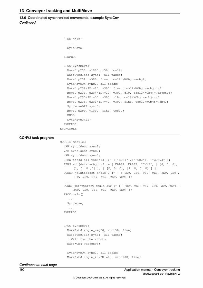
PROC main()
...
SyncMove;
...
ENDPROC
PROC SyncMove()
MoveJ p200, v1000, z50, tool2;
WaitSyncTask sync1, all_tasks;
MoveL p201, v500, fine, tool2 \WObj:=wobj2;
SyncMoveOn sync2, all_tasks;
MoveL p202\ID:=10, v300, fine, tool2\WObj:=wobjcnv3;
MoveC p203, p204\ID:=20, v300, z10, tool2\WObj:=wobjcnv3;
MoveL p205\ID:=30, v300, z10, tool2\WObj:=wobjcnv3;
MoveC p206, p201\ID:=40, v300, fine, tool2\WObj:=wobj2;
SyncMoveOff sync3;
MoveL p299, v1000, fine, tool2;
UNDO
SyncMoveUndo;
ENDPROC
ENDMODULE
CONV3 task programMODULE module3
VAR syncident sync1;
VAR syncident sync2;
VAR syncident sync3;
PERS tasks all_tasks{3} := [["ROB1"],["ROB2"], ["CONV3"]];
PERS wobjdata wobjcnv3 := [ FALSE, FALSE, "CNV3", [ [0, 0, 0],[1, 0, 0 ,0] ], [ [0, 0, 0], [1, 0, 0, 0] ] ];
CONST jointtarget angle_0 := [ [ 9E9, 9E9, 9E9, 9E9, 9E9, 9E9],[ 0, 9E9, 9E9, 9E9, 9E9, 9E9] ];
...
CONST jointtarget angle_360 := [ [ 9E9, 9E9, 9E9, 9E9, 9E9, 9E9],[360, 9E9, 9E9, 9E9, 9E9, 9E9] ];
PROC main()
...
SyncMove;
...
ENDPROC
PROC SyncMove()
MoveExtJ angle_neg20, vrot50, fine;
WaitSyncTask sync1, all_tasks;
! Wait for the robots
WaitWObj wobjcnv3;
SyncMoveOn sync2, all_tasks;
MoveExtJ angle_20\ID:=10, vrot100, fine;
Continues on next page190 Application manual - Conveyor tracking
3HAC050991-001 Revision: G© Copyright 2004-2018 ABB. All rights reserved.
13 Conveyor tracking and MultiMove13.6 Coordinated synchronized movements, example SyncCnvContinued
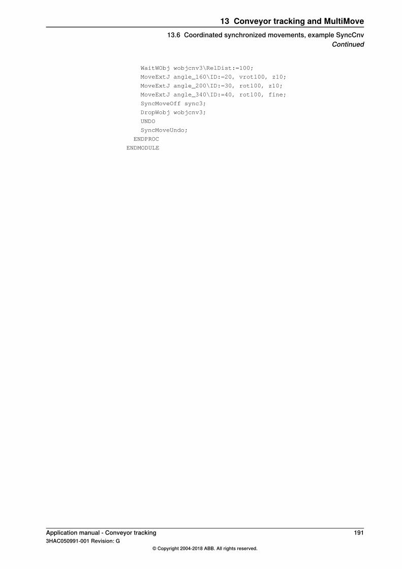
WaitWObj wobjcnv3\RelDist:=100;
MoveExtJ angle_160\ID:=20, vrot100, z10;
MoveExtJ angle_200\ID:=30, rot100, z10;
MoveExtJ angle_340\ID:=40, rot100, fine;
SyncMoveOff sync3;
DropWobj wobjcnv3;
UNDO
SyncMoveUndo;
ENDPROC
ENDMODULE
Application manual - Conveyor tracking 1913HAC050991-001 Revision: G
© Copyright 2004-2018 ABB. All rights reserved.
13 Conveyor tracking and MultiMove13.6 Coordinated synchronized movements, example SyncCnv
Continued

13.7 Motion principles
Robot speedsWhen the movements of several robots are synchronized, all robots adjust theirspeed to finish their movements simultaneously. This means that the robotmovement that takes the longest time will determine the speed of the other robots.
192 Application manual - Conveyor tracking3HAC050991-001 Revision: G
© Copyright 2004-2018 ABB. All rights reserved.
13 Conveyor tracking and MultiMove13.7 Motion principles
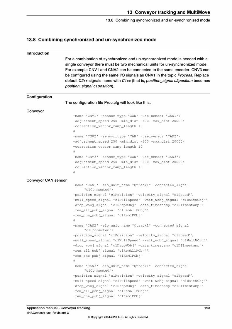
13.8 Combining synchronized and un-synchronized mode
IntroductionFor a combination of synchronized and un-synchronized mode is needed with asingle conveyor there must be two mechanical units for un-synchronized mode.For example CNV1 and CNV2 can be connected to the same encoder. CNV3 canbe configured using the same I/O signals as CNV1 in the topic Process. Replacedefault C2xx signals name with C1xx (that is, position_signal c2position becomesposition_signal c1position).
ConfigurationThe configuration file Proc.cfg will look like this:
Conveyor-name "CNV1" -sensor_type "CAN" -use_sensor "CAN1"\
-adjustment_speed 250 -min_dist -600 -max_dist 20000\
-correction_vector_ramp_length 10
#
-name "CNV2" -sensor_type "CAN" -use_sensor "CAN2"\
-adjustment_speed 250 -min_dist -600 -max_dist 20000\
-correction_vector_ramp_length 10
#
-name "CNV3" -sensor_type "CAN" -use_sensor "CAN3"\
-adjustment_speed 250 -min_dist -600 -max_dist 20000\
-correction_vector_ramp_length 10
#
Conveyor CAN sensor-name "CAN1" -eio_unit_name "Qtrack1" -connected_signal
"c1Connected"\
-position_signal "c1Position" -velocity_signal "c1Speed"\
-null_speed_signal "c1NullSpeed" -wait_wobj_signal "c1WaitWObj"\
-drop_wobj_signal "c1DropWObj" -data_timestamp "c1DTimestamp"\
-rem_all_pobj_signal "c1RemAllPObj"\
-rem_one_pobj_signal "c1Rem1PObj"
#
-name "CAN2" -eio_unit_name "Qtrack1" -connected_signal"c1Connected"\
-position_signal "c1Position" -velocity_signal "c1Speed"\
-null_speed_signal "c1NullSpeed" -wait_wobj_signal "c1WaitWObj"\
-drop_wobj_signal "c1DropWObj" -data_timestamp "c1DTimestamp"\
-rem_all_pobj_signal "c1RemAllPObj"\
-rem_one_pobj_signal "c1Rem1PObj"
#
-name "CAN3" -eio_unit_name "Qtrack1" -connected_signal"c1Connected"\
-position_signal "c1Position" -velocity_signal "c1Speed"\
-null_speed_signal "c1NullSpeed" -wait_wobj_signal "c1WaitWObj"\
-drop_wobj_signal "c1DropWObj" -data_timestamp "c1DTimestamp"\
-rem_all_pobj_signal "c1RemAllPObj"\
-rem_one_pobj_signal "c1Rem1PObj"
Application manual - Conveyor tracking 1933HAC050991-001 Revision: G
© Copyright 2004-2018 ABB. All rights reserved.
13 Conveyor tracking and MultiMove13.8 Combining synchronized and un-synchronized mode

This page is intentionally left blank

14 Troubleshooting14.1 Overview
IntroductionThis chapter details the various problem scenarios in conveyor tracking and howto troubleshoot those scenarios.
In this chapterThis chapter contains the following topics:
For more informationTopics
Event messages on page 196Event messages
System parameters on page 199System parameters
Robot path characteristics on page 200Robot path characteristics
Power failure on page 202Power failure
Collision detection on page 203Collision detection
Technical support on page 204Technical support
Application manual - Conveyor tracking 1953HAC050991-001 Revision: G
© Copyright 2004-2018 ABB. All rights reserved.
14 Troubleshooting14.1 Overview

14.2 Event messages
OverviewThis section details the different event messages and the information required totroubleshoot them.
Event messages
50082: Path calculation time exceededDescriptionThe path calculation time for mechanical units running in motion planner arg1exceeds internal limit. The motion task did not execute within its time limit.CauseThe CPU load is high. For example, due to frequent EIO communication.Recommended actionsThe following are the recommended actions:
• Set the system parameter High Interpolation Priority for the affectedmotion planner.
• Try to reduce the CPU load by one or more of the following actions:- Reduce speed.- Change AccSet.- Avoid singularity (SingArea\Wrist).- If the error occurs immediately after the start from finepoint, then
increase the configuration parameter Interpolation BufferStartup Adjust in the topic Motion and type Motion Planner.
• If using release 6.02.01 or 6.03.00 and the motion parameteroptimized_start_from_finepoint is set to 1, then set the parameter to0.
50163: Position adjustmentDescriptionExternal position adjustment too large. TCP speed, orientation speed, or externalposition speed exceed allowed robot performance.CauseThe following are the probable causes:
• Dynamic limitations of the robot.• Change in the robot’s direction at high speed.
Recommended actionsThe following are the recommended actions:
• Reduce the programmed TCP and orientation speeds.• Modify the path.• Ensure the program WaitWObj is closer to sync.• Run in AUTO.
Continues on next page196 Application manual - Conveyor tracking
3HAC050991-001 Revision: G© Copyright 2004-2018 ABB. All rights reserved.
14 Troubleshooting14.2 Event messages

• Tune adjustment_accel.• Set the configuration parameter in PROC adjustment_speed to 1.5 times
the maximum real conveyor speed. This modification is needed because theadjustment_speed is too low compared to the actual conveyor speed.
Note
Start tracking in zone with change of robot’s direction. Avoid starting the robotwith a movement that is opposite in direction to the conveyor’s movement.
50366: Reference errorDescriptionAn error has occurred in the reference calculation in motion planner arg1. Internalstatus arg2. As a consequence, the controller goes to Motors Off.CauseThe following are the probable causes:
• The robot path corrections are high.• The programmed TCP speed is high.• The robot is closely tracking the conveyor to a singularity. This usually
happens in six axis robots when axis 4 and 6 is in line. Often seen inapplications with roof hanging robots.
• The performance is reduced by the use of AccSet or PathAccLiminstructions.
• The corvec ramp is too short creating high acceleration.Recommended actionsThe following are the recommended actions:
• Check the error logs for previous errors that could be causing the presentproblem.
• Restart the program after moving the program pointer.• Restart the controller.• Set the robot speed slightly higher in RAPID.• Start tracking after MoveJ with big zone. Add a short linear movement.
50376: Geometric interpolation failedDescriptionTask. arg1.
Failed to interpolate the desired geometry.Program ref. arg2.
(Internal code: arg3).
CauseInterpolation can’t reach required divergence in the spline.Recommended actions
Continues on next pageApplication manual - Conveyor tracking 1973HAC050991-001 Revision: G
© Copyright 2004-2018 ABB. All rights reserved.
14 Troubleshooting14.2 Event messages
Continued

The following are the recommended actions:• Increase the zone size, move the programmed point, change the tool
orientation or change the interpolation method.• If using Robotware 6.02.xx or lower or if the robot type is different from
IRB360, IRB1200 and IRB1600, make the following changes in MOC.cfg :- SPLINE_PARAMETERS: -name "motion_special"
-max_spline_divergence 0.002
- MOTION_PLANNER: -name "motion_planner_1"-std_servo_queue_time 0.193536 -use_motion_sup "rob1"
-use_jog_parameters "motion_planner_1" -use_for_jogging
-repos_installed -use_spline_parameters
"motion_special" -restricted_circlepoint
50496: Conveyor Tracking position error at pickDescriptionActual TCP position for robot arg1 is too far away from the ordered position onconveyor arg2 due to ramping. Position error: arg3. As a consequence, the robotmay miss the picking or placing.CauseThe ramping of correction is not finished when reaching pick position.Recommended actionsThe following are the recommended actions:
• Increase the distance between pick and place positions to ensure that theramping is finished.
• Reduce programmed speed.• Reduce ramping length. Set the configuration parameter Start ramp and
Stop ramp in Process > Conveyor systems > parameters.• Increase the max allowed position error at pick or place position by setting
the configuration parameter Max tracking error at pick pos.
198 Application manual - Conveyor tracking3HAC050991-001 Revision: G
© Copyright 2004-2018 ABB. All rights reserved.
14 Troubleshooting14.2 Event messagesContinued

14.3 System parameters
OverviewThis section describes the troubleshooting steps for system parameters used inconveyor tracking.
Configuration processAs part of the configuration process (PROC.cfg), the following parameters shouldbe set to their corresponding values:
• adjustment_speed: This parameter should be set to 1.5 times the maximumactual conveyor speed.
• adjustment_accel: This parameter is not used by default, but can be tuneddepending on the type of the robot. Suggested values for IRB340 is 50000and for IRB660 is 7000.
• Acc_dependent_filter_value and sync_filter_speed_ratio:The parameter Acc_dependent_filter_value is used by default (1). Foraccelerating or indexing conveyors, it is recommended to turn it off (0). Forthe same applications, sync_filter_speed_ratio should be set to 0.0001.
Application manual - Conveyor tracking 1993HAC050991-001 Revision: G
© Copyright 2004-2018 ABB. All rights reserved.
14 Troubleshooting14.3 System parameters

14.4 Robot path characteristics
OverviewThis section describes the troubleshooting steps for robot path characteristicsused in conveyor tracking.
Changes to TCP speedAvoid making major changes to the speed during conveyor tracking, especially incase of larger robots.
Note
The programmed path should be close to the actual performance of the robot,as a smooth path results in a path with better accuracy.
Changes to direction• Avoid changing the direction of the robots at high speed.• Avoid start tracking in zone with change of the robot direction.• Avoid starting the robot’s movement in opposite to the direction of the
conveyor movement.
Changes to ramp lengthThe robot needs to ramp the conveyor tracking path corrections. During ramping,the robot is not in the correct position in relation to the conveyor. The ramp lengthcan be tuned using ‘Start ramp’ and ‘Stop ramp’ in the process configuration(Robotstudio names).
• correction_vector_ramp_length: Increasing the value of this processparameter (PROC.cfg) smoothens the movement but will also increase thedistance between the robot’s position in relation to the moving conveyor.Use a long ramp to reduce the mechanical stress in robot, and ensure tohave a longer path to the pick or place position.
• correction_vector_stop_ramp: Increasing the value of this processparameter (PROC.cfg) smoothens the movement at the end of tracking butcan affect the start tracking movement on next conveyor when switchingconveyor in zone.
Programming TCP speedIf the robot does not reach this speed, then avoid programing it to the maximumspeed (VelSet 100,10000;). Setting a speed that is close to the actual speed ofthe robot results in a smoother path and a better accuracy. The actual robot TCPspeed can be viewed in Robotstudio signal analyzer.If Robotstudio is not used, then the recommendation for IRB360 1.13 models isVelSet 100,7000 and for IRB360 1.6 and 1.8 models, it is VelSet 100,6000;For other models of robot, use VelSet 100,5000 in case of heavy load.If Pickmaster is used, then verify that the RAPID variable low speed is really lowin InitSpeed routine MaxSpeed.v_tcp:=Vtcp; LowSpeed.v_tcp:=Vtcp/3;
Continues on next page200 Application manual - Conveyor tracking
3HAC050991-001 Revision: G© Copyright 2004-2018 ABB. All rights reserved.
14 Troubleshooting14.4 Robot path characteristics

Ensure that low speed is set for vertical movements and between picks in case ofmultiple picks.
Jerky movementsJerky or rough robot movements are usually due to major path corrections whenramping out or when switching conveyors or during stop tracking.Check the program with high TCP speed on vertical movements and eventuallylimit acceleration by using the PathAccLim instruction.Low value on configuration parameter adjustment_speed can cause jerkymovements. Ensure the adjustment_speed is around 1.5 times the maximumconveyor speed.
I/O problemsDuring tracking, if the IRC5 controller loses I/O connection to the encoder interface,then a sys_stop occurs. To jog the robot, you need to change the Wobj programas the current one will be on the conveyor. Instead of trying to regain a positionon the conveyor, it is better to move the program pointer to the routine Main (PPto Main) to clear the current path.
Application manual - Conveyor tracking 2013HAC050991-001 Revision: G
© Copyright 2004-2018 ABB. All rights reserved.
14 Troubleshooting14.4 Robot path characteristics
Continued

14.5 Power failure
DescriptionDuring tracking, if the power fails, then the conveyor loses the connection. Aftera restart, the previous path is not recalculated. Move the program pointer to theroutine main (PP to Main).
202 Application manual - Conveyor tracking3HAC050991-001 Revision: G
© Copyright 2004-2018 ABB. All rights reserved.
14 Troubleshooting14.5 Power failure
14.6 Collision detection
DescriptionAfter a collision is detected, the movement is retracted using the joint interpolationmethod. The movement of the robot is related to the previous joint path and notthe conveyor. It is possible that the robot might move backward and collide again.However, from RobotWare 6.05 onwards it is possible to avoid the retractionmovement by using the switch \NoBackoff in the instruction MotionSup.
Application manual - Conveyor tracking 2033HAC050991-001 Revision: G
© Copyright 2004-2018 ABB. All rights reserved.
14 Troubleshooting14.6 Collision detection

14.7 Technical support
OverviewFor questions or problems with conveyor tracking, contact your local ABB RoboticsService representative, see http://www.abb.com/contacts. If the ABB Support teamneeds more information about errors, then the error logs can be activated by RAPIDroutine or service_debug.cmd file.
Robotware 5.15• RAPID routine:
VAR mocgendata mymocdata:=[0,0,0,0,0,0,"",""];
PROC uprobe_init()
mymocdata.value1:=8;
MocGenInstr 10008,mymocdata; mymocdata.value1:=1536;
mymocdata.value2:=0;
MocGenInstr 10009,mymocdata;
ENDPROC
If running a MultiMove system, the module containing the uprobe_init()
routine must be inserted in each RAPID task.• service_debug.cmd file:
Prior to the controller warm start, place the service_debug.cmd file in thesystem directory. The system directory is the one that contains HOME andSYSPAR directories. Ensure the service_debug.cmd file includes thefollowing two lines:
uprobe_set_mask -func statma_set_moc_uprobe_level -domain ipol_start-mask 8
uprobe_set_mask -func statma_set_moc_uprobe_level -domain servo-mask 1536
Robotware 5.61, 6.0 and higher• RAPID routine:
VAR mocgendata mymocdata:=[0,0,0,0,0,0,"",""];
PROC uprobe_init() mymocdata.value1:=1324;
MocGenInstr 10008,mymocdata;
ENDPROC
If running a MultiMove system, the module containing the uprobe_init() routinemust be inserted in each RAPID task.
• service_debug.cmd file :Prior to the controller warm start, place the service_debug.cmd file in thesystem directory. The system directory is the one that contains HOME andSYSPAR directories. Ensure the service_debug.cmd file includes thefollowing two lines:.
uprobe_set_mask -func statma_set_moc_uprobe_level -domainipol_start -mask 1324
204 Application manual - Conveyor tracking3HAC050991-001 Revision: G
© Copyright 2004-2018 ABB. All rights reserved.
14 Troubleshooting14.7 Technical support

IndexAaccelerating conveyors, 137ActivateProfile, 154activating conveyor, 89additional axes, 19additional conveyors, 84
Bbase frame calibration, 73
Ccircular conveyor tracking, 127CNV1
indexing conveyor, 160CnvGenInstr, 156conveyor base frame, 73coordinate systems, 23CountsPerMeter, 71–72counts per meter, 71–72
DDeactProfile, 155distance
maximum, 77minimum, 77
DropWObj, 110DSQC 377B, 39
Eencoder
prerequisites, 42selecting type, 40
Fframes, 23
Hhigh speed conveyors, 116
IIndCnvAddObject, 174indcnvdata, 170IndCnvDisable, 172IndCnvEnable, 172IndCnvInit, 171IndCnvReset, 173Indexing Conveyor Control
description, 159indexing mode, 160
Llimitations
Indexing Conveyor Control, 161LoadProfile, 153
MM7
indexing conveyor, 160motor, 39MultiMove, 179
independent, 179syncronized, 179
Oobject queue, 123
Ppaint applications, 39principles of conveyor tracking, 20
Qqueue tracking, 121queue tracking distance, 71–72QueueTrckDist, 71–72
RRecordProfile, 149replacing
xx, 148robot adjustment speed, 79
Ssafety, 13speed
robot, 79start window, 76StoreProfile, 152Sync Separation, 76
Ttrack motion, 19, 81
UUseAccProfile, 141
WWaitAndRecProf, 150WaitWObj, 107
Xxx
replacing, 148
Application manual - Conveyor tracking 2053HAC050991-001 Revision: G
© Copyright 2004-2018 ABB. All rights reserved.
Index


ABB AB, RoboticsRobotics and MotionS-721 68 VÄSTERÅS, SwedenTelephone +46 (0) 21 344 400
ABB AS, RoboticsRobotics and MotionNordlysvegen 7, N-4340 BRYNE, NorwayBox 265, N-4349 BRYNE, NorwayTelephone: +47 22 87 2000
ABB Engineering (Shanghai) Ltd.Robotics and MotionNo. 4528 Kangxin HighwayPuDong DistrictSHANGHAI 201319, ChinaTelephone: +86 21 6105 6666
ABB Inc.Robotics and Motion1250 Brown RoadAuburn Hills, MI 48326USATelephone: +1 248 391 9000
abb.com/robotics
3HAC050991-001,Rev
G,en
© Copyright 2004-2018 ABB. All rights reserved.Specifications subject to change without notice.