abbrobotics applicationmanual...
TRANSCRIPT

ABB Robotics
Application manualEtherNet/IP Fieldbus Adapter

Trace back information:Workspace RW 5-15-01 version a4Checked in 2013-04-03Skribenta version 4.0.006
Application manualEtherNet/IP Fieldbus Adapter
RobotWare 5.15
Document ID: 3HAC028509-001Revision: K
© Copyright 2007-2013 ABB. All rights reserved.

The information in this manual is subject to change without notice and should notbe construed as a commitment by ABB. ABB assumes no responsibility for any errorsthat may appear in this manual.Except as may be expressly stated anywhere in this manual, nothing herein shall beconstrued as any kind of guarantee or warranty by ABB for losses, damages topersons or property, fitness for a specific purpose or the like.In no event shall ABB be liable for incidental or consequential damages arising fromuse of this manual and products described herein.This manual and parts thereof must not be reproduced or copied without ABB'swritten permission.Additional copies of this manual may be obtained from ABB.The original language for this publication is English. Any other languages that aresupplied have been translated from English.
© Copyright 2007-2013 ABB. All rights reserved.ABB AB
Robotics ProductsSE-721 68 Västerås
Sweden
Table of contents7Overview ...........................................................................................................................................9Product documentation, M2004 .......................................................................................................
11Safety ................................................................................................................................................
131 Overview131.1 EtherNet/IP ......................................................................................................131.1.1 General .................................................................................................141.1.2 EtherNet/IP Fieldbus Adapter, IRC5 ............................................................151.2 CIP routing .......................................................................................................151.2.1 General .................................................................................................161.2.2 CIP routing, IRC5 ....................................................................................
172 Hardware description172.1 EtherNet/IP Fieldbus Adapter, DSQC 669 ..............................................................
213 Configuration213.1 EtherNet/IP Fieldbus Adapter configuration ............................................................213.1.1 Introduction to configuration ......................................................................283.1.2 Configuration overview .............................................................................303.1.3 Working with the EtherNet/IP Fieldbus Adapter .............................................353.2 CIP routing configuration ....................................................................................353.2.1 Introduction ............................................................................................363.2.2 Configuration overview .............................................................................383.2.3 Working with CIP routing ..........................................................................
434 System parameters434.1 Introduction ......................................................................................................454.2 Type Bus .........................................................................................................454.2.1 EtherNet/IP Address ................................................................................464.2.2 EtherNet/IP Subnet Mask ..........................................................................474.2.3 EtherNet/IP Gateway ................................................................................484.2.4 Connector ID ..........................................................................................494.3 Type Unit Type .................................................................................................494.3.1 Input Size ..............................................................................................504.3.2 Output Size ............................................................................................514.4 Type Route ......................................................................................................514.4.1 Name ....................................................................................................524.4.2 Connected to Bus ....................................................................................534.4.3 Port ID ..................................................................................................
55Index
3HAC028509-001 Revision: K 5© Copyright 2007-2013 ABB. All rights reserved.
Table of contents

This page is intentionally left blank
OverviewAbout this manual
This manual describes the EtherNet/IP Fieldbus Adapter option and containsinstructions for the EtherNet/IP Fieldbus Adapter configuration.
UsageThis manual should be used during installation and configuration of the EtherNet/IPFieldbus Adapter and upgrading of the EtherNet/IP Fieldbus Adapter option.
Who should read this manual?This manual is intended for
• Personnel that are responsible for installations and configurations of fieldbushardware/software
• Personnel that make the configurations of the I/O system• System integrators
PrerequisitesThe reader should have the required knowledge of
• Mechanical installation work• Electrical installation work
Organization of chaptersThe manual is organized in the following chapters:
ContentsChapter
This chapter gives an overview of the EtherNet/IP Fieldbus Adapter and in-cludes following:
• A general description of EtherNet/IP and CIP routing• Description of how the EtherNet/IP Fieldbus Adapter is connected in
a robot system• Description of how CIP routing is used in a robot system
1
This chapter describes the EtherNet/IP Fieldbus Adapter hardware.2
This chapter gives an overview of the EtherNet/IP Fieldbus Adapter configur-ation and the CIP routing configuration. The chapter also contains descriptionsof workflows.
3
This chapter describes the EtherNet/IP Fieldbus Adapter specific systemparameters.
4
References
Document references
Document IDReference
3HAC020676-001Application manual - DeviceNet
3HAC032104-001Operating manual - RobotStudio
3HAC16590-1Operating manual - IRC5 with FlexPendant
3HAC021313-001Product manual - IRC5
Continues on next page3HAC028509-001 Revision: K 7
© Copyright 2007-2013 ABB. All rights reserved.
Overview

Document IDReference
3HAC17076-1Technical reference manual - System para-meters
3HAC021785-001Product specification, IRC5 with FlexPendant
Other references
DescriptionReference
The web site of ODVA (Open DeviceNetVendor Association).
www.odva.org
ODVA SpecificationCommon Industrial Protocol (CIP) Edition 3.0
ODVA SpecificationEtherNet/IP Specification Edition 1.2
Revisions
DescriptionRevision
First edition. RobotWare 5.09.-
Description of CIP routing is added.A
The predefined Unit Type ENIP_SLAVE_FA is changed to EN_SLAVE_FA.B
The system parameters EtherNet/IP Address, EtherNet/IP Subnet Mask andEtherNet/IP gateway now belong to the type Bus.
C
The Output/Assembly section is added in the EtherNet/IP Fieldbus Adapterconfiguration >Configuration overview section of theConfiguration chapter.
D
Updated for the RW 5.13 release.EChanges in the Configuration chapter.
• Updated the table in the section Configuration overview on page 28.• Added the subsectionViewingMACAddress on page33 in theWorking
with the EtherNet/IP Fieldbus Adapter section.• Added cross reference to Operating manual - IRC5 with FlexPendant
in the sectionConfiguring the EtherNet/IP Fieldbus Adapter on page30.
Updated for the RW 5.14 release.FThe value for the Connection size is updated in the table in the subsectionSpecification overview on page 14.Information about the location of the EDS file in the RobotWare DVD, PC, andIRC5 Controller is added in the following section:
• Electronic Data Sheet file on page 28• Electronic Data Sheet file on page 36
Updated for the RW 5.14.02 release.• Added the new system parameter Connector ID.
G
Updated the Limitations section in Configuration overview on page 28 for theRW 5.14.03 release.
H
Updated the Introduction section in the chapterSystem parameters on page43for RW 5.15 release.
J
Updated for the RW 5.15.01 release.• Removed the notes in Description fromEtherNet/IP Address on page45.• The subnet mask allowed values are changed from "255.255.255.0 -
255.255.255.254" to "128.0.0.0 - 255.255.255.252" in EtherNet/IP SubnetMask on page 46.
• Updated the screenshots of RobotStudio 5.15 throughout.
K
8 3HAC028509-001 Revision: K© Copyright 2007-2013 ABB. All rights reserved.
Overview
Continued
Product documentation, M2004Categories for manipulator documentation
The manipulator documentation is divided into a number of categories. This listingis based on the type of information in the documents, regardless of whether theproducts are standard or optional.All documents listed can be ordered from ABB on a DVD. The documents listedare valid for M2004 manipulator systems.
Product manualsManipulators, controllers, DressPack/SpotPack, and most other hardware will bedelivered with a Product manual that generally contains:
• Safety information.• Installation and commissioning (descriptions of mechanical installation or
electrical connections).• Maintenance (descriptions of all required preventive maintenance procedures
including intervals and expected life time of parts).• Repair (descriptions of all recommended repair procedures including spare
parts).• Calibration.• Decommissioning.• Reference information (safety standards, unit conversions, screw joints, lists
of tools ).• Spare parts list with exploded views (or references to separate spare parts
lists).• Circuit diagrams (or references to circuit diagrams).
Technical reference manualsThe technical reference manuals describe reference information for roboticsproducts.
• Technical reference manual - Lubrication in gearboxes: Description of typesand volumes of lubrication for the manipulator gearboxes.
• Technical reference manual - RAPID overview: An overview of the RAPIDprogramming language.
• Technical referencemanual - RAPID Instructions, Functions and Data types:Description and syntax for all RAPID instructions, functions, and data types.
• Technical reference manual - RAPID kernel: A formal description of theRAPID programming language.
• Technical reference manual - System parameters: Description of systemparameters and configuration workflows.
Application manualsSpecific applications (for example software or hardware options) are described inApplication manuals. An application manual can describe one or severalapplications.
Continues on next page3HAC028509-001 Revision: K 9
© Copyright 2007-2013 ABB. All rights reserved.
Product documentation, M2004

An application manual generally contains information about:• The purpose of the application (what it does and when it is useful).• What is included (for example cables, I/O boards, RAPID instructions, system
parameters, DVD with PC software).• How to install included or required hardware.• How to use the application.• Examples of how to use the application.
Operating manualsThe operating manuals describe hands-on handling of the products. The manualsare aimed at those having first-hand operational contact with the product, that isproduction cell operators, programmers, and trouble shooters.The group of manuals includes (among others):
• Operating manual - Emergency safety information• Operating manual - General safety information• Operating manual - Getting started, IRC5 and RobotStudio• Operating manual - Introduction to RAPID• Operating manual - IRC5 with FlexPendant• Operating manual - RobotStudio• Operatingmanual - Trouble shooting IRC5, for the controller and manipulator.
10 3HAC028509-001 Revision: K© Copyright 2007-2013 ABB. All rights reserved.
Product documentation, M2004
Continued
SafetySafety of personnel
When working inside the robot controller it is necessary to be aware ofvoltage-related risks.A danger of high voltage is associated with the following parts:
• Units inside the controller, for example I/O units, can be supplied with powerfrom an external source.
• The mains supply/mains switch.• The power unit.• The power supply unit for the computer system (230 VAC).• The rectifier unit (400-480 VAC and 700 VDC). Capacitors!• The drive unit (700 VDC).• The service outlets (115/230 VAC).• The power supply unit for tools, or special power supply units for the
machining process.• The external voltage connected to the controller remains live even when the
robot is disconnected from the mains.• Additional connections.
Therefore, it is important that all safety regulations are followed when doingmechanical and electrical installation work.
Safety regulationsBefore beginning mechanical and/or electrical installations, ensure you are familiarwith the safety regulations described in Product manual - IRC5.
3HAC028509-001 Revision: K 11© Copyright 2007-2013 ABB. All rights reserved.
Safety

This page is intentionally left blank

1 Overview1.1 EtherNet/IP
1.1.1 General
What is EtherNet/IP?EtherNet/IP is a communications link to connect industrial devices.The EtherNet/IP (EtherNet Industrial Protocol) is managed by ODVA (OpenDeviceNet Vendors Association). It is a well established industrial Ethernetcommunication system with good real-time capabilities. EtherNet/IP extendscommercial off-the-shelf Ethernet to the CIP (Common Industrial Protocol)— thesame upper-layer protocol and object model found in DeviceNet and ControlNet.CIP allows EtherNet/IP and DeviceNet system integrators and users to apply thesame objects and profiles for plug-and-play interoperability among devices frommultiple vendors and in multiple sub-nets. Combined, DeviceNet, ControlNet andEtherNet/IP promote transparency from sensors to the enterprise software.
Examples of applicationsHere are some examples of EtherNet/IP applications:
• Peer-to-peer data exchange where an EtherNet/IP product can produce andconsume messages
• Master/slave operation defined as a proper subset of peer-to-peer• An EtherNet/IP product can function as a client or server, or both
EtherNet/IP standardizationEtherNet/IP is standardized according to the International standard IEC 61158 andEtherNet/IP devices are certified by ODVA for interoperability and conformance.
Facts, EtherNet/IPThe following table specifies a number of facts about EtherNet/IP.
Ethernet based Control Level network with CIP application protocolNetwork type
Standard Off the Shelf (COTS) Ethernet cables and connectors.Installation10/100/1000 Mbit/s TX Ethernet cable or fibre optics.RJ45, M12 or fibre optic connectors.
10, 100, 1000 Mbit/sSpeed
Electronic Data Sheet fileThe configuration process is based on EDS files (Electronic Data Sheet) which arerequired for each EtherNet/IP device. EDS files are provided by the devicemanufacturers and contain electronic descriptions of all relevant communicationparameters and objects of the EtherNet/IP device.
3HAC028509-001 Revision: K 13© Copyright 2007-2013 ABB. All rights reserved.
1 Overview1.1.1 General
1.1.2 EtherNet/IP Fieldbus Adapter, IRC5
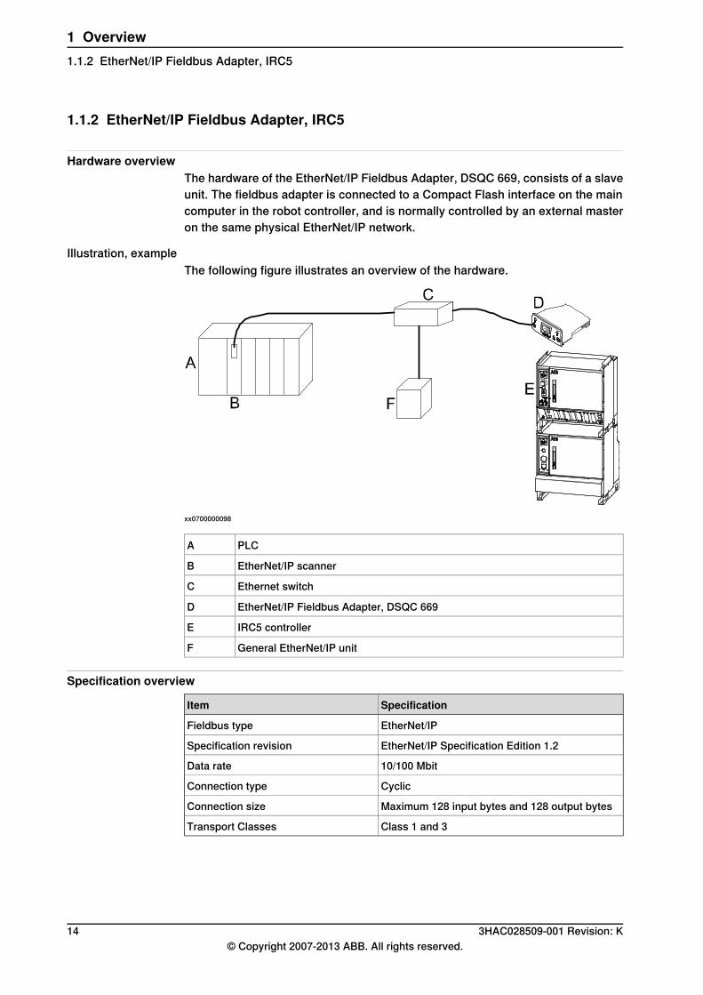
Hardware overviewThe hardware of the EtherNet/IP Fieldbus Adapter, DSQC 669, consists of a slaveunit. The fieldbus adapter is connected to a Compact Flash interface on the maincomputer in the robot controller, and is normally controlled by an external masteron the same physical EtherNet/IP network.
Illustration, exampleThe following figure illustrates an overview of the hardware.
xx0700000098
PLCA
EtherNet/IP scannerB
Ethernet switchC
EtherNet/IP Fieldbus Adapter, DSQC 669D
IRC5 controllerE
General EtherNet/IP unitF
Specification overview
SpecificationItem
EtherNet/IPFieldbus type
EtherNet/IP Specification Edition 1.2Specification revision
10/100 MbitData rate
CyclicConnection type
Maximum 128 input bytes and 128 output bytesConnection size
Class 1 and 3Transport Classes
14 3HAC028509-001 Revision: K© Copyright 2007-2013 ABB. All rights reserved.
1 Overview1.1.2 EtherNet/IP Fieldbus Adapter, IRC5

1.2 CIP routing
1.2.1 General
What is CIP routingCIP (Common Industrial Protocol) routing makes it possible to collect and viewstatus or other information from different devices placed on several CIP networksat a single or several operator stations. A CIP router allows sending messagesbetween CIP networks.
CIP standardizationCIP is standardized by ODVA. CIP devices are certified by ODVA for interoperabilityand conformance.
Electronic Data Sheet fileThe configuration process is based on EDS files (Electronic Data Sheet) which arerequired for each CIP device. EDS files are provided by the device manufacturersand contain electronic descriptions of all relevant communication parameters andobjects of the CIP device. The EDS files contain essential information about CIProuting.
3HAC028509-001 Revision: K 15© Copyright 2007-2013 ABB. All rights reserved.
1 Overview1.2.1 General
1.2.2 CIP routing, IRC5
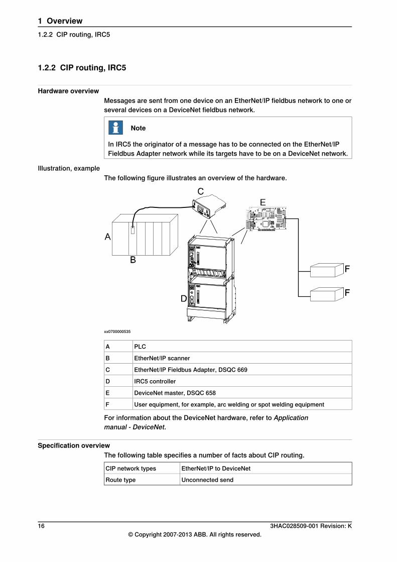
Hardware overviewMessages are sent from one device on an EtherNet/IP fieldbus network to one orseveral devices on a DeviceNet fieldbus network.
Note
In IRC5 the originator of a message has to be connected on the EtherNet/IPFieldbus Adapter network while its targets have to be on a DeviceNet network.
Illustration, exampleThe following figure illustrates an overview of the hardware.
xx0700000535
PLCA
EtherNet/IP scannerB
EtherNet/IP Fieldbus Adapter, DSQC 669C
IRC5 controllerD
DeviceNet master, DSQC 658E
User equipment, for example, arc welding or spot welding equipmentF
For information about the DeviceNet hardware, refer to Applicationmanual - DeviceNet.
Specification overviewThe following table specifies a number of facts about CIP routing.
EtherNet/IP to DeviceNetCIP network types
Unconnected sendRoute type
16 3HAC028509-001 Revision: K© Copyright 2007-2013 ABB. All rights reserved.
1 Overview1.2.2 CIP routing, IRC5
2 Hardware description2.1 EtherNet/IP Fieldbus Adapter, DSQC 669
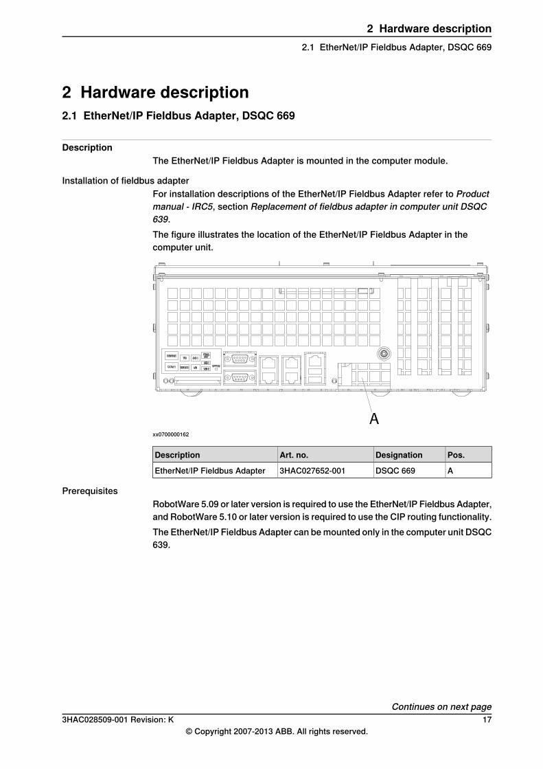
DescriptionThe EtherNet/IP Fieldbus Adapter is mounted in the computer module.
Installation of fieldbus adapterFor installation descriptions of the EtherNet/IP Fieldbus Adapter refer to Productmanual - IRC5, section Replacement of fieldbus adapter in computer unit DSQC639.The figure illustrates the location of the EtherNet/IP Fieldbus Adapter in thecomputer unit.
xx0700000162
Pos.DesignationArt. no.Description
ADSQC 6693HAC027652-001EtherNet/IP Fieldbus Adapter
PrerequisitesRobotWare 5.09 or later version is required to use the EtherNet/IP Fieldbus Adapter,and RobotWare 5.10 or later version is required to use the CIP routing functionality.The EtherNet/IP Fieldbus Adapter can be mounted only in the computer unit DSQC639.
Continues on next page3HAC028509-001 Revision: K 17
© Copyright 2007-2013 ABB. All rights reserved.
2 Hardware description2.1 EtherNet/IP Fieldbus Adapter, DSQC 669
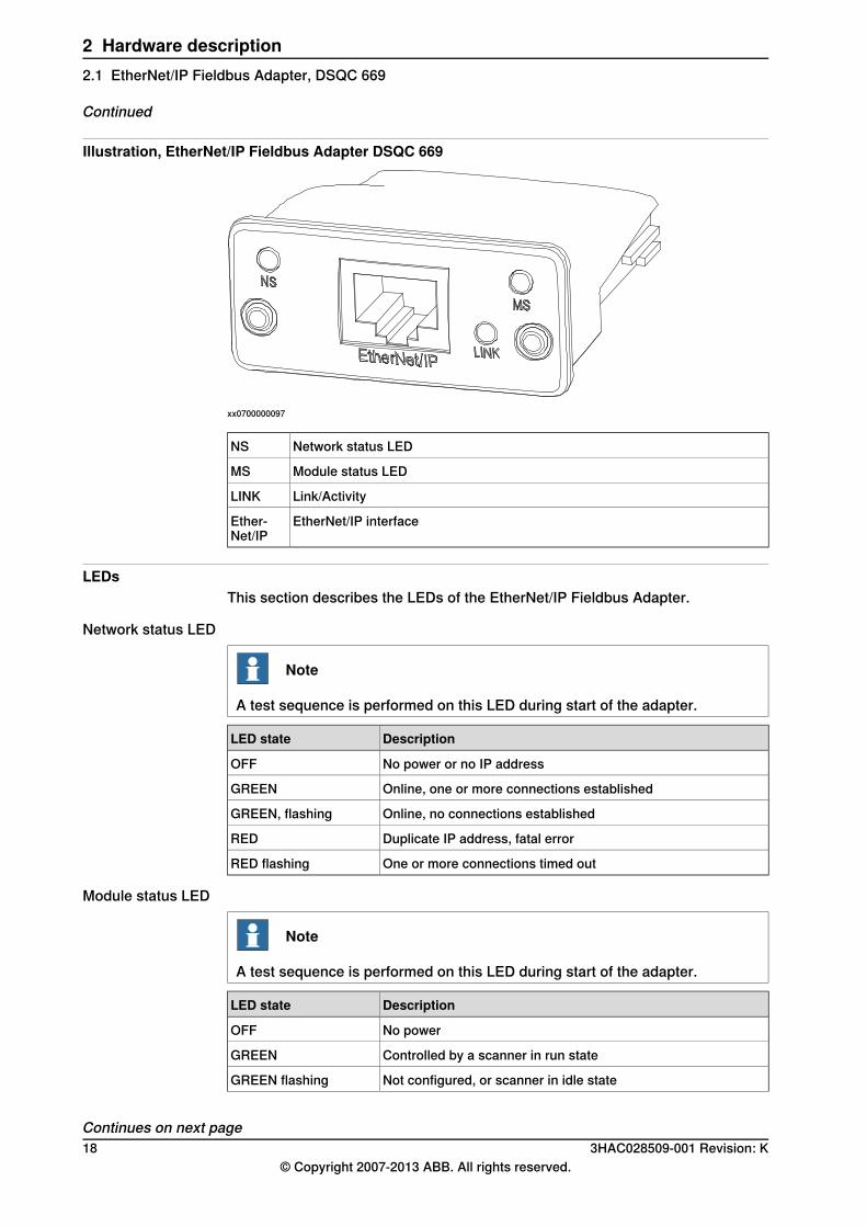
Illustration, EtherNet/IP Fieldbus Adapter DSQC 669
xx0700000097
Network status LEDNS
Module status LEDMS
Link/ActivityLINK
EtherNet/IP interfaceEther-Net/IP
LEDsThis section describes the LEDs of the EtherNet/IP Fieldbus Adapter.
Network status LED
Note
A test sequence is performed on this LED during start of the adapter.
DescriptionLED state
No power or no IP addressOFF
Online, one or more connections establishedGREEN
Online, no connections establishedGREEN, flashing
Duplicate IP address, fatal errorRED
One or more connections timed outRED flashing
Module status LED
Note
A test sequence is performed on this LED during start of the adapter.
DescriptionLED state
No powerOFF
Controlled by a scanner in run stateGREEN
Not configured, or scanner in idle stateGREEN flashing
Continues on next page18 3HAC028509-001 Revision: K
© Copyright 2007-2013 ABB. All rights reserved.
2 Hardware description2.1 EtherNet/IP Fieldbus Adapter, DSQC 669
Continued

DescriptionLED state
Major fault (exception state, fatal error etc.)RED
Recoverable fault(s)RED flashing
Link/Activity LED
DescriptionLED state
No link, no activityOFF
Link establishedGREEN
ActivityGREEN flickering
Cable lengths
Permanent link lengthThe total permanent link length for COTS twisted pair systems is limited to 90 m(298 ft). The permanent link shall conform to ANSI/TIA/EIA-568-B1. Refer toEtherNet/IP Specification Edition 1.2.
Channel lengthThe total channel length for COTS twisted pair systems is 100 m (330 ft) includingpatch cables as defined in ANSI/TIA/EIA-568-B1. Refer to EtherNet/IP SpecificationEdition 1.2.
Continues on next page3HAC028509-001 Revision: K 19
© Copyright 2007-2013 ABB. All rights reserved.
2 Hardware description2.1 EtherNet/IP Fieldbus Adapter, DSQC 669
Continued

This page is intentionally left blank

3 Configuration3.1 EtherNet/IP Fieldbus Adapter configuration
3.1.1 Introduction to configuration
Controller softwareThe IRC5 controller must be installed with software that supports the use of theEtherNet/IP network, that is, the EtherNet/IP Fieldbus Adapter option must beinstalled.For a information on how to add the EtherNet/IP Fieldbus Adapter option, seeOperating manual - RobotStudio.
PC softwareRobotStudio is a PC software that is used to setup connections to robots and towork with robots.The configuration for the EtherNet/IP communication is done either manually usingRobotStudio, or by loading a configuration file from RobotStudio. For informationon how to work with RobotStudio, see Operating manual - RobotStudio.
Explicit Messaging servicesIt is possible to configure I/O units through explicit messaging services. This couldbe done either at startup by defining the Fieldbus Commands to the configuredunit, or at runtime from RAPID through the Fieldbus Command Interface (FCI). Formore information, refer to Technical reference manual - RAPID Instructions,Functions and Data types, and Application manual - Robot communication and I/Ocontrol, section Fieldbus Command Interface.For the explicit messaging at startup:
1 Use RobotStudio to define a Fieldbus Command type that is general to theunit type and could be used by many EtherNet/IP units of this unit type.
2 Use RobotStudio to define a Fieldbus Command that is specific to a certainunit and that specifies the unit specific data to be send to the unit. TheFieldbus Command is linked to a certain unit. The data defined in the valueparameter should fit the instance or attribute size on the EtherNet/IP unit.
The EtherNet/IP specific system parameters in the Fieldbus Command type are:• Path (-EN_Path)• Service (-EN_Service)
For more information, refer to the EtherNet/IP Specification or the Applicationmanual - Robot communication and I/O control.
Continues on next page3HAC028509-001 Revision: K 21
© Copyright 2007-2013 ABB. All rights reserved.
3 Configuration3.1.1 Introduction to configuration
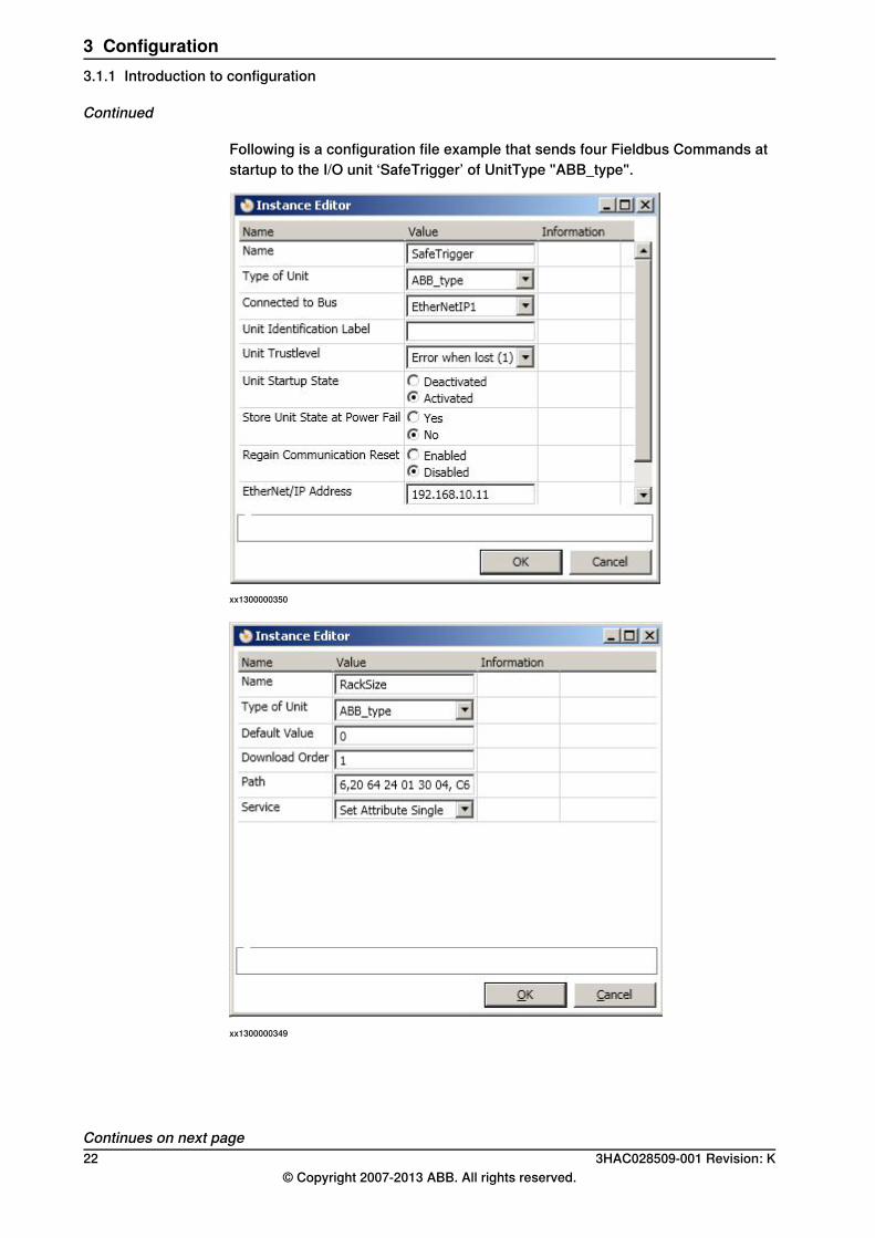
Following is a configuration file example that sends four Fieldbus Commands atstartup to the I/O unit ‘SafeTrigger’ of UnitType "ABB_type".
xx1300000350
xx1300000349
Continues on next page22 3HAC028509-001 Revision: K
© Copyright 2007-2013 ABB. All rights reserved.
3 Configuration3.1.1 Introduction to configuration
Continued
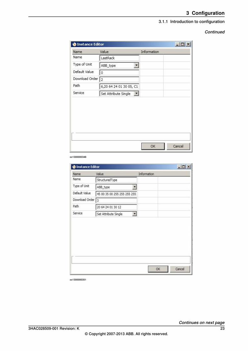
xx1300000348
xx1300000351
Continues on next page3HAC028509-001 Revision: K 23
© Copyright 2007-2013 ABB. All rights reserved.
3 Configuration3.1.1 Introduction to configuration
Continued

xx1300000347
The preceding example shows how to use the -EN_Path and -EN_Serviceparameters. If a Class, Instance, or Attribute below 0x10 is specified, it is importantto include a "0" before the value. For example, the value 8 is written as 08 in the-EN_Path string.Following is a short description of the syntax used in the -EN_Path parameter.
"Path length, 20 Class 24 Instance 30 Attribute, Data type, Data typelength"
The following table provides a description of the parameters used in the syntax:
DescriptionParameter
The byte count for the "20 64 24 01 30 05" string.Path lengthThis is an optional parameter.
The EtherNet/IP Class number.Class
The instance number of the class.Instance
The attribute of the specified instance.Attribute
The data format of the attribute.Data typeThis is an optional parameter.
The length in bytes of the specified Data type. The highest al-lowed value is 0x20 (32 bytes).
Data type length
This parameter is ignored, but is accepted if entered.
DescriptionValueData Type
Logical Boolean with values TRUE and FALSEC1CIP_EXPL_BOOL
Signed 8-bit integer valueC2CIP_EXPL_SINT
Signed 16-bit integer valueC3CIP_EXPL_INT
Continues on next page24 3HAC028509-001 Revision: K
© Copyright 2007-2013 ABB. All rights reserved.
3 Configuration3.1.1 Introduction to configuration
Continued

DescriptionValueData Type
Unsigned 8-bit integer valueC6CIP_EXPL_USINT
Unsigned 16-bit integer valueC7CIP_EXPL_UINT
Unsigned 32-bit integer valueC8CIP_EXPL_UDINT
32-bit floating point valueCACIP_EXPL_REAL
Character string (1 byte per character)D0CIP_EXPL_STRING
Bit string - 8-bitsD1CIP_EXPL_BYTE
Bit string - 16-bitsD2CIP_EXPL_WORD
Bit string - 32-bitsD3CIP_EXPL_DWORD
Character string (1 byte per character, 1 byte length indicator)DACIP_EXPL_SHORT_STRING
Array values
ExampleDescriptionData Type
"123 214 125 2 44"The values are delimited byspace.
CIP_EXPL_BOOLCIP_EXPL_SINT An array of 5 elements. The
Data Type specifies the typeof each element.
CIP_EXPL_INTCIP_EXPL_USINTCIP_EXPL_UINTCIP_EXPL_UDINTCIP_EXPL_REALCIP_EXPL_BYTECIP_EXPL_WORDCIP_EXPL_DWORD
"Hello;This;Is;My;Name"The values are delimited bysemicolon.
CIP_EXPL_STRINGCIP_EXPL_SHORT_STRING An array of 5 elements of
string type.
The -EN_Service parameter describes what type of operation that should beperformed against the specified -EN_Path parameter.Following are the allowed values for -EN_Service:
DescriptionValueOperation
Set the value specified in '-DefValue' or EIO_COMMAND.16Set
Get the specified parameter.14Get
Performs a reset of the specified I/O unit.5Reset
The-OrderNr parameter is used to specify in what order the commands are sendto the I/O unit.If an FCI command is rejected by the I/O unit, the EtherNet/IP master will generatean event message with the error code returned by the I/O unit.
Fieldbus commands via RAPIDIn this example, data packed as a rawbytes variable is read from an EtherNet/IPI/O unit.
PROC get_quickconnect_value()
VAR iodev dev;
VAR rawbytes rawdata_out;
Continues on next page3HAC028509-001 Revision: K 25
© Copyright 2007-2013 ABB. All rights reserved.
3 Configuration3.1.1 Introduction to configuration
Continued

VAR rawbytes rawdata_in;
VAR num input_int;
VAR byte return_status;
VAR byte return_errcodecnt;
VAR num return_errcode;
VAR byte value;
! Empty contents of rawdata_out and rawdata_in
ClearRawBytes rawdata_out;
ClearRawBytes rawdata_in;
! Add Fieldbus command header to rawdata_out with
! service "GET_ATTRIBUTE_SINGLE" and
! path to QuickConnect attribute on I/0 unit.
PackDNHeader "0E", "6,20 F5 24 01 30 0C",
rawdata_out;
! Open FCI device
Open "/FCI1:" \File:="TheUnit", dev \Bin;
! Write the contents of rawdata_out to dev
WriteRawBytes dev, rawdata_out
\NoOfBytes := RawBytesLen(rawdata_out);
! Read the answer from dev
ReadRawBytes dev, rawdata_in;
! Close FCI device
Close dev;
! Unpack rawdata_in to the variable return_status
UnpackRawBytes rawdata_in, 1, return_status
\Hex1;
! The first byte is always the general status byte. 0 meanssuccess, see the CIP standard error codes.
IF return_status = 0 THEN
TPWrite "Status OK from device. Status code: "
\Num:=return_status;
! Unpack the read data value that follows the status byte.
UnpackRawBytes rawdata_in, 2, value \Hex1;
TPWrite "Read value: " \Num:=value;
ELSE
! If the general status was not ok there is extended errorinformation that can be retreived. First byte, after thegeneral status byte, tells
! how many extended error words can be found.
UnpackRawBytes rawdata_in, 2, return_errcodecnt
\Hex1;
! Unpack the number of extended status words. In this exampleonly the first one is unpacked.
Continues on next page26 3HAC028509-001 Revision: K
© Copyright 2007-2013 ABB. All rights reserved.
3 Configuration3.1.1 Introduction to configuration
Continued

UnpackRawBytes rawdata_in, 3, return_errcode
\IntX := UINT;
TPWrite "Error code from device: "
\Num:=return_status;
TPWrite "Additional error code count from device: "
\Num:=return_errcodecnt;
TPWrite "Additional error code from device: "
\Num:=return_errcode;
ENDIF
ENDPROC
3HAC028509-001 Revision: K 27© Copyright 2007-2013 ABB. All rights reserved.
3 Configuration3.1.1 Introduction to configuration
Continued

3.1.2 Configuration overview
ConfigurationThe following table gives descriptions of defining the types Bus and Unit Type forthe EtherNet/IP Fieldbus Adapter.
DescriptionDefining...
An EtherNet/IP Fieldbus Adapter bus must be defined with a valid IP ad-dress before starting the communication.
Bus
When creating a unit type, some system parameters are fieldbus specific.Unit TypeUnit specific values can be found in the EDS file (Electronic Data Sheet)for the unit, see Electronic Data Sheet file on page 28.See also Type Unit Type on page 49.
An I/O unit must be defined in the configuration before any master is ableto connect, and to see any activity on the LEDs.
Unit
For general information, see Technical reference manual - System para-meters.
For general information, see Technical reference manual - System para-meters.
Signal
Predefined BusWhen the system is installed with the EtherNet/IP Fieldbus Adapter option, apredefined bus EtherNetIP_FA1 is created.
Predefined Unit TypeA predefined Unit Type for the fieldbus adapter, EN_SLAVE_FA, is definedsupporting a cyclic connection with the size of 64 input bytes and 64 output bytesas defined in the signal configuration for the fieldbus adapter.If another input or output size on the fieldbus adapter is required, the predefinedUnit Type must be modified or a new Unit Type must be created.
LimitationsThe EtherNet/IP Fieldbus Adapter has the following limitations:
• The predefined Unit Type (EN_SLAVE_FA) has 128 input bytes and 128output bytes, but this number can be increased or decreased to the restrictionin the I/O system (see Input Size on page 49 and Output Size on page 50).
• For the EtherNet/IP Fieldbus Adapter both the input and output map startsat bit 0
Related informationTechnical reference manual - System parameters
Electronic Data Sheet fileAn EDS file, ENIP_FA.eds, for the EtherNet/IP Fieldbus Adapter, matching theconfiguration of the predefined Unit Type EN_SLAVE_FA, is located at the followinglocations:
• On the RobotWare DVD: <DVD-drive>:\utility\fieldbus\EtherNetIP\EDS\• OnthePCwheretheRobotWareisinstalled: ...\ABBIndustrialIT\
RoboticsIT\Mediapool\<RobotWare_xx.xx.xxxx>\utility\service\EDS\
Continues on next page28 3HAC028509-001 Revision: K
© Copyright 2007-2013 ABB. All rights reserved.
3 Configuration3.1.2 Configuration overview
• On the IRC5 Controller: \hd0a\<RobotWare_xx.xx.xxxx>\utility\service\EDS\If another input or output size than the predefined is used, it is recommended thatthe values in the EDS file are edited to match the new system parameter values.
Note
If the EDS file is edited it will not be considered as a certified file.
Example, EDS fileAn example from an EDS file when changing the predefined output and input sizesfrom 128 bytes to 16 bytes:
[Params]
Param1 =
"Output Size",$ name
0,128,16, $ min, max, default data values
Param2 =
"Input Size",$ name
0,128,16,$ min, max, default data values
Input/Output AssemblyThe input and output assemblies are used by an EtherNet/IP master to locate theinput and output data in the EtherNet/IP Fieldbus Adapter. For EtherNet/IP FieldbusAdapter, the input assembly is 150 and the output assembly is 100.
I/O connectionCyclic I/O connection is supported and the size of the I/O connection is defined bythe type Unit Type.
Note
If the EtherNet/IP Fieldbus Adapter loses connection with the scanner, theconfigured input signals are cleared (reset to zero).When the connection is re-established, the scanner updates the input signals.
3HAC028509-001 Revision: K 29© Copyright 2007-2013 ABB. All rights reserved.
3 Configuration3.1.2 Configuration overview
Continued
3.1.3 Working with the EtherNet/IP Fieldbus Adapter
UsageWhen the IRC5 controller is connected, for example, to an external PLC it can beconfigured as shown in Illustration, example on page 30.
PrerequisitesThe network address of the EtherNet/IP Fieldbus Adapter must be known.
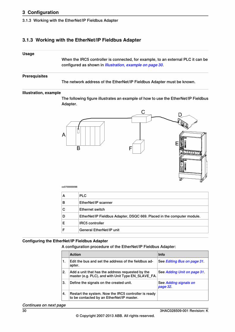
Illustration, exampleThe following figure illustrates an example of how to use the EtherNet/IP FieldbusAdapter.
xx0700000098
PLCA
EtherNet/IP scannerB
Ethernet switchC
EtherNet/IP Fieldbus Adapter, DSQC 669. Placed in the computer module.D
IRC5 controllerE
General EtherNet/IP unitF
Configuring the EtherNet/IP Fieldbus AdapterA configuration procedure of the EtherNet/IP Fieldbus Adapter:
InfoAction
See Editing Bus on page 31.Edit the bus and set the address of the fieldbus ad-apter.
1.
See Adding Unit on page 31.Add a unit that has the address requested by themaster (e.g. PLC), and with Unit Type EN_SLAVE_FA.
2.
See Adding signals onpage 32.
Define the signals on the created unit.3.
Restart the system. Now the IRC5 controller is readyto be contacted by an EtherNet/IP master.
4.
Continues on next page30 3HAC028509-001 Revision: K
© Copyright 2007-2013 ABB. All rights reserved.
3 Configuration3.1.3 Working with the EtherNet/IP Fieldbus Adapter

Note
For information about configuring I/O using FlexPendant, refer to the ConfiguringI/O section in the Handling inputs and outputs, I/O chapter in Operatingmanual - IRC5 with FlexPendant.
Editing Bus
Action
In RobotStudio, click Configuration Editor and select I/O.1.
Click Bus, then double-click on the bus you want to edit.2.
In the Edit Bus dialog box, type the values for the parameters.
en0900000124
3.
Adding Unit
Action
In RobotStudio, click Configuration Editor and select I/O.1.
Click Unit, then right-click in the workspace and select Add Unit.2.
Continues on next page3HAC028509-001 Revision: K 31
© Copyright 2007-2013 ABB. All rights reserved.
3 Configuration3.1.3 Working with the EtherNet/IP Fieldbus Adapter
Continued
Action
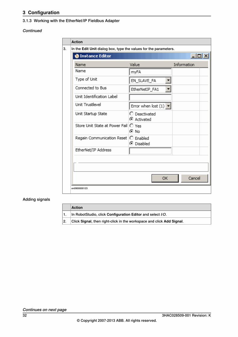
In the Edit Unit dialog box, type the values for the parameters.
en0900000123
3.
Adding signals
Action
In RobotStudio, click Configuration Editor and select I/O.1.
Click Signal, then right-click in the workspace and click Add Signal.2.
Continues on next page32 3HAC028509-001 Revision: K
© Copyright 2007-2013 ABB. All rights reserved.
3 Configuration3.1.3 Working with the EtherNet/IP Fieldbus Adapter
Continued
Action
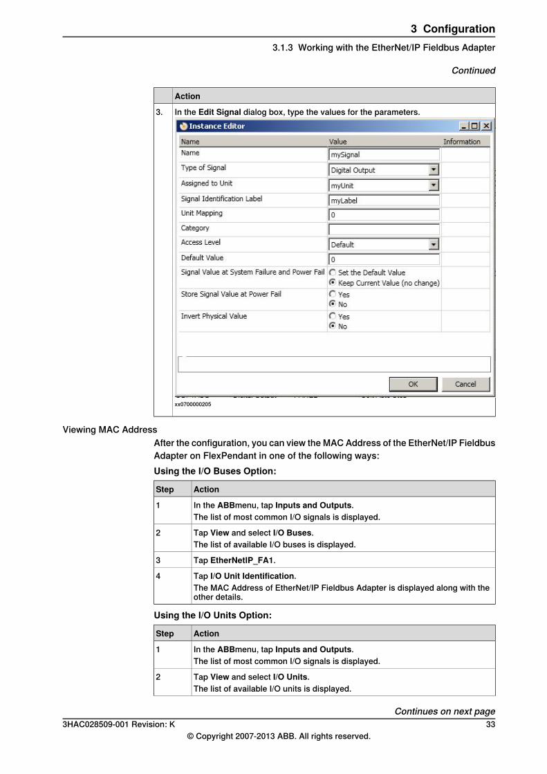
In the Edit Signal dialog box, type the values for the parameters.
xx0700000205
3.
Viewing MAC AddressAfter the configuration, you can view the MAC Address of the EtherNet/IP FieldbusAdapter on FlexPendant in one of the following ways:Using the I/O Buses Option:
ActionStep
In the ABBmenu, tap Inputs and Outputs.1The list of most common I/O signals is displayed.
Tap View and select I/O Buses.2The list of available I/O buses is displayed.
Tap EtherNetIP_FA1.3
Tap I/O Unit Identification.4The MAC Address of EtherNet/IP Fieldbus Adapter is displayed along with theother details.
Using the I/O Units Option:
ActionStep
In the ABBmenu, tap Inputs and Outputs.1The list of most common I/O signals is displayed.
Tap View and select I/O Units.2The list of available I/O units is displayed.
Continues on next page3HAC028509-001 Revision: K 33
© Copyright 2007-2013 ABB. All rights reserved.
3 Configuration3.1.3 Working with the EtherNet/IP Fieldbus Adapter
Continued
ActionStep
Tap the I/O unit created to Ethernet/IP fieldbus adapter.3
Tap Actions and select I/O Unit Identification.4The MAC Address of EtherNet/IP Fieldbus Adapter is displayed along with theother details.
Related informationOperating manual - RobotStudio.
34 3HAC028509-001 Revision: K© Copyright 2007-2013 ABB. All rights reserved.
3 Configuration3.1.3 Working with the EtherNet/IP Fieldbus Adapter
Continued

3.2 CIP routing configuration
3.2.1 Introduction
Controller softwareThe IRC5 controller must be installed with software that supports the use of theCIP networks. To communicate through the EtherNet/IP network the EtherNet/IPFieldbus Adapter option must be installed, while DeviceNet communication requiresone DeviceNet option to be installed.For description of how to add the EtherNet/IP Fieldbus Adapter and DeviceNetoptions, see Operating manual - RobotStudio.
PC softwareRobotStudio is a PC software that is used to set up connections to robots and towork with robots.The configuration for the EtherNet/IP and DeviceNet communication is done eithermanually using RobotStudio, or by loading a configuration file from RobotStudio.For information about how to work with RobotStudio refer to Operatingmanual - RobotStudio, see References on page 7.
3HAC028509-001 Revision: K 35© Copyright 2007-2013 ABB. All rights reserved.
3 Configuration3.2.1 Introduction

3.2.2 Configuration overview
ConfigurationA routing configuration requires that two or more routes are defined. One routebonds the required CIP port to a CIP network. Messages can be fowarded to anyof the networks having a CIP port defined.The following table gives descriptions of all route specific types.
DescriptionDefining...
A route identity links the required CIP port to a destinationnetwork.
CIP Route
Port identityThe port identity, required by the CIP route protocol, is used in order to find adestination network. By the configuration the port identity is tied to a specificnetwork/bus. Each network has its own unique port identity.
Electronic Data Sheet fileAn EDS file (Electronic Data Sheet) for the EtherNet/IP Fieldbus Adapter, matchingthe configuration of the predefined Unit Type EN_SLAVE_FA, is located at thefollowing locations:
• On the RobotWare DVD: <DVD-drive>:\utility\fieldbus\EtherNetIP\EDS\• OnthePCwheretheRobotWareisinstalled: ...\ABB Industrial IT\
RoboticsIT\Mediapool\<RobotWare_xx.xx.xxxx>\utility\service\EDS\• On the IRC5 Controller: \hd0a\<RobotWare_xx.xx.xxxx>\utility\service\EDS\
The file contains information necessary for the CIP routing.
Example, EDS fileAn example from an EDS file that shows the configurations of the ports:
[Port]
Port1 =
TCP,$ port type name
"TCP/IP",$ name of port
"20 F5 24 01", $ instance one of the TCP/IP interface $ object
2;$ port number
Port2 =
DeviceNet,$ port type
"DeviceNet1",$ port name
"20 03 24 01",$ path to object supporting this port-DNet $object
3;$ port number
Port3 =
DeviceNet,$ port type
"DeviceNet2",$ port name
"20 03 24 01",$ path to object supporting this port-DNet $object
Continues on next page36 3HAC028509-001 Revision: K
© Copyright 2007-2013 ABB. All rights reserved.
3 Configuration3.2.2 Configuration overview
4;$ port number
3HAC028509-001 Revision: K 37© Copyright 2007-2013 ABB. All rights reserved.
3 Configuration3.2.2 Configuration overview
Continued
3.2.3 Working with CIP routing
UsageWhen the IRC5 controller is connected, for example, to an external PLC it can beconfigured as Illustration, example on page 38.
The function of CIP routingA message on one route can be forwaded to any of the other defined routes. Thesent message contains the destination device and port number, and from thatinformation the suitable destination route is selected. All defined CIP routes willtogether compose a virtual CIP router. During the configuration of a route the portnumber will be coupled with its network or fieldbus and thereby with its hardware.
PrerequisitesFieldbuses to use in the CIP network have to be of type EtherNet/IP and DeviceNet.The RobotWare options EtherNet/IP and DeviceNet are required for usage of CIProuting. All DeviceNet equipment to be used with CIP routing must be configuredwith the IRC5 master. In order to reach a DeviceNet equipment with a messagevia CIP routing, the Explicit messaging parameter must be set in the DeviceNetconfiguration.
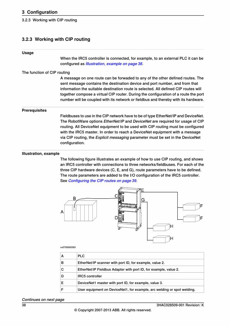
Illustration, exampleThe following figure illustrates an example of how to use CIP routing, and showsan IRC5 controller with connections to three networks/fieldbuses. For each of thethree CIP hardware devices (C, E, and G), route parameters have to be defined.The route parameters are added to the I/O configuration of the IRC5 controller.See Configuring the CIP routes on page 39.
xx0700000393
PLCA
EtherNet/IP scanner with port ID, for example, value 2.B
EtherNet/IP Fieldbus Adapter with port ID, for example, value 2.C
IRC5 controllerD
DeviceNet1 master with port ID, for example, value 3.E
User equipment on DeviceNet1, for example, arc welding or spot welding.F
Continues on next page38 3HAC028509-001 Revision: K
© Copyright 2007-2013 ABB. All rights reserved.
3 Configuration3.2.3 Working with CIP routing

DeviceNet2 master with port ID, for example, value 4.G
User equipment on DeviceNet2, for example, arc welding or spot welding.H
In this example there are two possible routes:• From port ID 2 to port ID 3, and further to equipment on the DeviceNet1
network.• From port ID 2 to port ID 4, and further to equipment on the DeviceNet2
network.
Note
The maximum number of ports depends on total number of DeviceNet channels- that is, 2 + number of DeviceNet channels. See Port ID on page 53.
Configuring the CIP routesA configuration procedure of the CIP routes that details how to add a route toEtherNet/IP, DeviceNet1 and DeviceNet2 by using RobotStudio:
Action
In RobotStudio, click Configuration Editor and select I/O.1.
Click Route, then right-click in the workspace and select Add Route.2.
In the Edit Route dialog box, type the values for the parameters to add a route toEtherNet/IP. Click OK.
xx0700000395
3.
Continues on next page3HAC028509-001 Revision: K 39
© Copyright 2007-2013 ABB. All rights reserved.
3 Configuration3.2.3 Working with CIP routing
Continued

Action
To add a route to DeviceNet1, proceed with step 2 above.4.In the Edit Route dialog box, type the values for the parameters to add a route toDeviceNet1. Click OK.
xx0700000536
To add a route to DeviceNet2, proceed with step 2 above.5.In the Edit Route dialog box, type the values for the parameters to add a route toDeviceNet2. Click OK.
xx0700000537
Continues on next page40 3HAC028509-001 Revision: K
© Copyright 2007-2013 ABB. All rights reserved.
3 Configuration3.2.3 Working with CIP routing
Continued

Action
Restart the system.6.
LimitationsCIP routing has the following limitations:
• Max. routes: A maximum of 5 routes can be defined.• Unconnected send connection: Only unconnected send service routing is
supported.• Explicit message connection: This is the only supported connection type. In
order to see or use a DeviceNet device it has to allow Explicit messageconnection.
• I/O message connection: Unsupported connection type.• Single hop: The router cannot act as an intermediate hop, that is, the router
cannot forward a message to its target when it has to go through anotherrouter.
• EtherNet/IP: An EtherNet/IP route only has server capability. A server willonly respond to a received request.
• DeviceNet: A DeviceNet route only has client capability. A client will issue arequest and expects an answer to its request.
Related informationWorking with the EtherNet/IP Fieldbus Adapter on page 30.Application manual - DeviceNet.Operating manual - RobotStudio.
3HAC028509-001 Revision: K 41© Copyright 2007-2013 ABB. All rights reserved.
3 Configuration3.2.3 Working with CIP routing
Continued

This page is intentionally left blank

4 System parameters4.1 Introduction
About the system parametersThere are both EtherNet/IP specific parameters and more general parameters. Thischapter describes all EtherNet/IP specific system parameters. The parameters aredivided into the type they belong to.For information about other system parameters, see Technical referencemanual - System parameters.
EtherNet/IP system parameters
BusThese parameters belong to the type Bus in the topic I/O.
For more information, see ...Parameter
Technical reference manual - System parametersName
Technical reference manual - System parametersType of Bus
Connector ID on page 48Connector ID
Technical reference manual - System parametersLabel of Fieldbus Connect-or
Technical reference manual - System parametersUnit Recovery Time
EtherNet/IP Address on page 45EtherNet/IP Address
EtherNet/IP Subnet Mask on page 46EtherNet/IP Subnet Mask
EtherNet/IP Gateway on page 47EtherNet/IP Gateway
Unit TypeThese parameters belong to the type Unit Type in the topic I/O.
For more information, see ...Parameter
Technical reference manual - System parametersName
Technical reference manual - System parametersType of Bus
Technical reference manual - System parametersVendor Name
Technical reference manual - System parametersProduct Name
Technical reference manual - System parametersInternal Slave
Input Size on page 49Input Size
Output Size on page 50Output Size
RouteThese parameters belong to the type Route in the topic I/O.
For more information, see ...Parameter
Technical reference manual - System parametersName
Technical reference manual - System parametersType of Bus
Connected to Bus on page 52Connected to Bus
Continues on next page3HAC028509-001 Revision: K 43
© Copyright 2007-2013 ABB. All rights reserved.
4 System parameters4.1 Introduction

For more information, see ...Parameter
Port ID on page 53Port ID
44 3HAC028509-001 Revision: K© Copyright 2007-2013 ABB. All rights reserved.
4 System parameters4.1 Introduction
Continued

4.2 Type Bus
4.2.1 EtherNet/IP Address
ParentEtherNet/IP Address belongs to the type Bus, in the topic I/O.
Cfg nameEN_Address
DescriptionThe parameter EtherNet/IP Address specifies the IP address of the EtherNet/IPFieldbus Adapter that uses on the network. This IP address is used by an externalmaster to set up a connection to the fieldbus adapter.
PrerequisitesThe option EtherNet/IP Fieldbus Adapter must be installed.
Allowed valuesAllowed values are between 0.0.0.0 - 255.255.255.255.
Note
If the IP address of the LAN port is left empty, the EtherNet/IP Master/Slave willuse the already assigned IP address for the IRC5 controller.
3HAC028509-001 Revision: K 45© Copyright 2007-2013 ABB. All rights reserved.
4 System parameters4.2.1 EtherNet/IP Address
4.2.2 EtherNet/IP Subnet Mask
ParentEtherNet/IP Subnet Mask belongs to the type Bus, in the topic I/O.
Cfg nameEN_SubnetMask
DescriptionThe EtherNet/IP Subnet Mask is used to determine what subnet the IP addressbelongs to.
UsageEtherNet/IP Subnet Mask is an EtherNet/IP specific parameter.
PrerequisitesThe option EtherNet/IP Fieldbus Adapter must be installed.
Allowed valuesAllowed values are between 128.0.0.0 - 255.255.255.252.
Note
If the Subnet Mask of the LAN port is left empty, the EtherNet/IP Master/Slavewill use the already assigned Subnet Mask for the IRC5 controller.
46 3HAC028509-001 Revision: K© Copyright 2007-2013 ABB. All rights reserved.
4 System parameters4.2.2 EtherNet/IP Subnet Mask
4.2.3 EtherNet/IP Gateway
ParentEtherNet/IP Gateway belongs to the type Bus, in the topic I/O.
Cfg nameEN_Gateway
DescriptionEtherNet/IP Gateway specifies the node on the network that serves as an entranceto another network.
UsageUse this parameter if the EtherNet/IP traffic needs to be routed to anothersub-network. The parameter value is the address to a physical gateway on theEtherNet/IP network.EtherNet/IP Gateway is an EtherNet/IP specific parameter.
Note
A destination address must be specified if the gateway address is specified.
PrerequisitesThe option EtherNet/IP Fieldbus Adapter must be installed.
Allowed valuesAllowed values are between 0.0.0.0 - 255.255.255.255.
3HAC028509-001 Revision: K 47© Copyright 2007-2013 ABB. All rights reserved.
4 System parameters4.2.3 EtherNet/IP Gateway
4.2.4 Connector ID
ParentConnector ID belongs to the type Bus, in the topic I/O.
Cfg nameConnectorID
DescriptionThe parameter Connector ID specifies the hardware interface (connection port)that the option EtherNet/IP fieldbus adapter shall use.
UsageTheConnector ID parameter is used to select one of the available connection portsto use.
PrerequisitesThe option EtherNet/IP fieldbus adapter (840-1) must be installed.
Default valueFieldbus Adapter
Allowed valuesFieldbus Adapter
48 3HAC028509-001 Revision: K© Copyright 2007-2013 ABB. All rights reserved.
4 System parameters4.2.4 Connector ID

4.3 Type Unit Type
4.3.1 Input Size
ParentInput Size belongs to the type Unit Type, in the topic I/O.
Cfg nameEN_InputSize
DescriptionThe parameter Input Size defines the data size in bytes for the input area receivedfrom the unit.
UsageInput Size is an EtherNet/IP specific parameter.
PrerequisitesThe option EtherNet/IP Fieldbus Adapter must be installed.
LimitationsA limitation is the maximum unit size for the Unit Type.
Default valueThe default value is 8.
Allowed valuesAllowed values are the integers 0-128, specifying the input data size in bytes.
3HAC028509-001 Revision: K 49© Copyright 2007-2013 ABB. All rights reserved.
4 System parameters4.3.1 Input Size

4.3.2 Output Size
ParentOutput Sizebelongs to the type Unit Type, in the topic I/O.
Cfg nameEN_OutputSize
DescriptionOutput Size defines the data size in bytes for the output area received from theunit.
UsageOutput Size is an EtherNet/IP specific parameter.
PrerequisitesThe option EtherNet/IP Fieldbus Adapter must be installed.
LimitationsA limitation is the maximum unit size for the Unit Type.
Default valueThe default value is 8.
Allowed valuesAllowed values are the integers 0-128, specifying the output data size in bytes.
50 3HAC028509-001 Revision: K© Copyright 2007-2013 ABB. All rights reserved.
4 System parameters4.3.2 Output Size

4.4 Type Route
4.4.1 Name
ParentName belongs to the type Route, in the topic I/O.
Cfg nameName
DescriptionThe parameter Name specifies the name of the route.
UsageName specifies a route, to which the route messages can be received or sent to.
PrerequisitesEtherNet/IP Fieldbus Adapter and the DeviceNet option must be installed.
Default valueThe default value is an empty string
Allowed valuesThe value can be a string of characters.
3HAC028509-001 Revision: K 51© Copyright 2007-2013 ABB. All rights reserved.
4 System parameters4.4.1 Name
4.4.2 Connected to Bus
ParentConnected to Bus belongs to the type Route, in the topic I/O.
Cfg nameBus
DescriptionThe parameter Connected to Bus specifies the name of the I/O network.
UsageConnected to Bus shows which network is associated to a certain port.
PrerequisitesEtherNet/IP Fieldbus Adapter and the DeviceNet option must be installed.
Default valueThe default value is an empty string.
Allowed valuesThe value can be any defined I/O bus name.
52 3HAC028509-001 Revision: K© Copyright 2007-2013 ABB. All rights reserved.
4 System parameters4.4.2 Connected to Bus
4.4.3 Port ID
ParentPort ID belongs to the type Route, in the topic I/O.
Cfg namePort ID
DescriptionThe parameter Port ID specifies the connector of the I/O network.
UsagePort ID is used in the CIP routing path.
PrerequisitesEtherNet/IP Fieldbus Adapter and the DeviceNet option must be installed.
Default valueThe default value is 2.
Allowed valuesThe value can be from 2 to (2 + number of installed DeviceNet channels).
Note
Value 1 is reserved and is not allowed to use.
3HAC028509-001 Revision: K 53© Copyright 2007-2013 ABB. All rights reserved.
4 System parameters4.4.3 Port ID

This page is intentionally left blank
IndexCcable length, 19channel length, 19CIP, 13CIP router, 15CIP routing, 15–16
CIP port, 36configuration, 36, 39function, 38limitations, 41port identity, 36
Common Industrial Protocol, 15configuration, CIP routing, 39Connector ID, 48controller software, 21, 35ControlNet, 13
DDeviceNet, 13DSQC 639, 17DSQC 658, 16DSQC 667, 17DSQC 669, 14, 16, 18, 30
EEDS file, 13, 15, 36EtherNet/IP, 13
configuration, 21specification, 13–14standardization, 13
EtherNet/IP fieldbus adapter, 14, 16, 30configuration, 30hardware, 14installation, 17limitations, 28predefined Bus, 28predefined Unit Type, 28
EtherNet/IP network, 14ethernet switch, 30
Ffieldbus adapter, 17
installation, 17
II/O connection, 29
cyclic, 29input assembly, 29
LLED, 18
link/activity, 19module status, 18network status, 18test, 18
MMAC Address, 33
OODVA, 13output assembly, 29
PPROFIBUS fieldbus adapter, 17
Ssafety, 11system parameters
Connected to Bus, 52EtherNet/IP Address, 45EtherNet/IP Gateway, 47EtherNet/IP Subnet Mask, 46Input Size, 49Name, 51Output Size, 50Port ID, 53
Ttopic I/O type
Bus, 28, 31, 43Unit, 28, 31, 43Unit Type, 28, 43
3HAC028509-001 Revision: K 55© Copyright 2007-2013 ABB. All rights reserved.
Index


Contact us
ABB ABDiscrete Automation and MotionRoboticsS-721 68 VÄSTERÅS, SwedenTelephone +46 (0) 21 344 400
ABB AS, RoboticsDiscrete Automation and MotionBox 265N-4349 BRYNE, NorwayTelephone: +47 51489000
ABB Engineering (Shanghai) Ltd.5 Lane 369, ChuangYe RoadKangQiao Town, PuDong DistrictSHANGHAI 201319, ChinaTelephone: +86 21 6105 6666
ABB Inc.Discrete Automation and MotionRobotics1250 Brown RoadAuburn Hills, MI 48326USATelephone: +1 248 391 9000
www.abb.com/robotics
3HAC
0285
09-0
01,R
evK,
en