roborodentia 2016: scorpion tyler whalen cpe 462 spring
TRANSCRIPT

Roborodentia 2016: Scorpion
Tyler Whalen CPE 462 Spring 2016
June 8, 2016 Advisor: John Seng

Table of Contents Introduction 2
Problem Statement 2
Robot Specifications 3
Preliminary Design Decisions 4
Last Minute Design Decisions 6
Software 9
Hardware 11
Mechanical 12
Bill of Materials 19
Lessons Learned/Improvements 20
Conclusion 21
References 22
Appendix 22
1

Introduction This report showcases my entry into the Roborodentia 2016 competition, and my senior
project. I chose this project because robotics has always interested me, and this was a great opportunity to jump in headfirst.
I will step through my design decisions and detail all information necessary for replicating this build. Problem Statement I am given a course and the task to design, develop, and test an autonomous robot to compete against other robots. The goal this year was to score the most points by moving rings from supply pegs to scoring pegs. Rings are placed in groups of 4 on vertical pegs. Engineers had the option of scoring on ‘Scoring Pegs #1’ for 1 point/ring or ‘Scoring Pegs #2’ for 3 points/ring. Engineers also had the option to carry yellow rings to scoring pegs. Yellow rings are worth 3 points/ring and every stack of rings containing a yellow ring has its point value multiplied by three.
Figure 1: The course layout for Roborodentia 2016 [1]
2

Robot Specifications[1]
1. Robots must be fully autonomous and selfcontained.
2. Robots must have an 12” x 12” footprint or smaller at beginning of the match, but may autonomously expand after the match begins. At any point during a match, a robot’s footprint may not be larger than 14” x 14”.
3. A robot may have a maximum height of 15” at the start of a match. There is no height
restriction after the match begins.
4. A robot may not disassemble into multiple parts.
5. Robots may not use any RF wireless receivers/transmitters during the competition.
6. Robots may not damage the course or the contest rings.
7. Adhesives may be used to pick up rings, but the rings may not be modified in any way. A ring must be completely free of residue after it has been picked up.
8. If a robot has RF wireless components onboard, the contestant will be required to notify
the judges before the competition, and be able to demonstrate that the wireless components are not used. If RF components are found onboard that were not declared, or declared nonoperational when active, it will be grounds for immediate disqualification.
9. Intentionally jamming an opponent's sensors is not allowed. Robots may not have
weaponry or devices designed to damage or impede the operation of an opponent’s robot.
10. A robot may not disturb rings on an opponent’s side of the field.
11. A robot may not fly.
3

Preliminary Design Decisions GOAL: To make a simple but consistent robot that could always score an average of 6 rings. I decided to use Scoring Pegs #1 and to ignore the yellow rings and rings in the box.
2 motorized wheels with 1 front balancing wheel Not planning on using Scoring Pegs #2 so extra motorized wheels in the front were
overkill and wasted power Use of Seng’s Roboshield
Streamlined development with useful encoder functions, LCD display for testing purposes, and analog/digital input ports with library functions
Use of 3 IR sensor/emitters for line following 2 for center line following, detects drift off the line and allows robot to correct itself
Figure 2: The center line IR followers
4

1 for turn detection, detects the center cross on the course to trigger turning
Figure 3: The turn detector IR sensor
Use of linear actuator kit I had no mechanical background entering this project and after researching
solutions for robotic linear motion, decided to buy something prepackaged to allow focus on software/consistency
Bought and tested a cheap Motorized Slide Potentiometer There was no simple way to attach a claw/grabbing mechanism to pick up
rings It was too weak to carry the mass required (servo, claw casing, 4 rings)
Settled on Acrobotics Channel Slider Kit Guaranteed to carry required mass Sturdy, consistent, easytoassemble Easy to attach a claw
Vertical ring grabbing approach Channel Slider kit lended itself to this method of picking up rings
Channel kit attachment points made it awkward to attach a horizontal claw Allowed robot to be more consistent
If correctly aligned, this method almost always allowed for picking up of all 4 rings, so it was very binary; 4 rings(correctly aligned) or 0 rings(incorrectly aligned)
Allowed for focus on correct alignment, because if alignment is consistent, it will always grab all 4 rings
Use of AA battery pack Convenient and familiar Cheap, bulk buying options
5

Last Minute Design Decisions These are design decisions I made close to the competition date. These decisions were made mostly due to testing on the course. Testing the robot on the course illuminated problems I had not previously considered.
Need to raise the arm with a piece of wood
Figure 4: The block that is raising column
12 inch track was barely too short and 15 inch track was too long I raised the column 23 cm using a small block of wood so the rings would clear the
tip of the pegs Shave of screw on top column to meet height specification
Figure 5: Top of column after shaving screw
6

After inserting the small block at the base, the robot was a few centimeters taller than 15 inches.
As per requirement #3 in the ‘Robot Specifications’ section, I shaved it off with an angle grinder to get the robot a couple centimeters below 15 inches.
Modified claw to better hold 4 rings
Figure 6: Modified claw with inner wall and rubber grips
Without the walls, only the bottom ring would stay still. The rest would inconsistently wobble around inside the claw
Without the rubber, the bottom ring sometimes fell out Used old debit card because it is thin and relatively strong Used shoe leather because it is grippy and readily available
7

Extra, fourth, sensor in the back for consistent alignment
Figure 7: Back sensor for pickUp/dropOff alignment
During testing on the course, it was nigh impossible to align the claw with the rings using only the 3 initial sensors
I added a new sensor in the back using velcro, so the robot could consistently stop while approaching the rings
Velcro was used because there was no further opportunities to get into the machine shop, and it allowed for easy trial and error positioning while testing on the course
Raised column the tiniest bit more to allow for more consistent clearing of the vertical peg
Figure 8: Small spacer to fix clipping issue
8

There was some amount of inconsistency with how high the claw would rise, and the rings would catch on the pegs every few trials.
I added a spacer on top of the small piece of wood and below the metal track and the small raise stopped it from clipping. The spacer can any thin piece of plastic/wood/metal.
Software State Based Solution: The code flows through 6 states detailed below
state = 0: driving to center from dropoff pegs state = 1: driving to pickup pegs from center state = 2: picking up at pickup pegs state = 3: driving to center from pickup pegs state = 4: driving to dropoff pegs from center state = 5: dropping off at dropoff pegs
By the competition rules, robots must start at the pickup pegs, So my program starts at state 2. State Diagram
Figure 9: State Diagram for course algorithm
9

Functions (Figure 4): drive():
Drive() checks for a turn by calling checkTurn(). checkTurn() uses the turn sensor (Figure 3) to check for black tape. Due to the design of the course, and how I broke up my states, I know that every time this sensor sees black tape, I stop driving straight and perform a new action.
If checkTurn() is false, drive() uses the 2 center sensors (Figure 2) to keep alignment with the center drive line. It makes corrective measures if either of the 2 sensors is off the line
If checkTurn() is true, then checkTurn() performs an action dependent on the current state,
and moves the state forward. State 0: checkTurn() turns left to face the pickUp pegs State 1: checkTurn() does nothing extra and immediately transitions state to State 2 State 2: does not use checkTurn() State 3: checkTurn() turns right to face the dropOff pegs State 4: checkTurn() does nothing extra and immediately transitions state to State 5 State 5: does not use checkTurn()
ring_drive():
The goal of this function is to position the robot over the pegs consistently so the pickUp/dropOff functions can do their job assuming correct position.
ringDrive() behaves similarly to drive() except instead of using the sensor from Figure 3, it uses the back sensor from Figure 7 to know when the robot is far enough forward. This sensor was placed through trial and error to determine where it should be to allow the arm to be over the rings.
Once ring_drive() determines that the back sensor sees the tape, it returns and pickUpRings()/dropOffRings() is called depending on the state. pickUpRings()/dropOffRings():
These functions assume the arm is directly over the pickUp/dropOff pegs, and they simply pick up rings, or drop off rings.
pickUpRings() moves the arm down a distance defined by the #define ARM_DIST, closes the claw using servo control, and moves the arm back up.
dropOffRings() simply opens the claw with servo control. The rings are dropped from the highest position and the arm doesn’t move at all. This is to save time in dropOff.
After performing their respective ring action, both of theses functions turn the robot around to face the center and move the state variable up, so the robot can drive for the center of the course.
10

Hardware
Figure 10: Hardware diagram for RoboShield connections
Figure 10 shows almost all of the usermade electrical connections in the project. The final usermade connection is the RoboShield sitting on top of an Arduino MEGA 2560. The RoboShield should be fitted on top of the Arduino with the text ‘ROBOSHIELD’ in the bottom right corner in the same direction as the text ‘ARDUINO MEGA’ in the bottom right corner of the Arduino. In other words, both texts are upright. The shield takes a majority of the Arduino’s analog/digital pins and its power pins. No connections are made with the Arduino besides the RoboShield sitting on top of it. For replication purposes, the motors and IR sensors will need to be setup as shown above to be compatible with the code provided in the Appendix. However, the #define’s ‘CLAW_OPEN’ and ‘CLAW_CLOSE’ will need to be updated based on the arm position of the servo used in replicating this project. Below is a legend (Table 1) making clear any abbreviations used above.
11

A0A3 Analog pins 0 through 3
M1 M3 Motor pins 1 through 3; M2 & M3 have special 6 pin headers on the board
S7 Servo pin 7
SP System power
IR0 turn sensor
IR1 right center sensor(perspective: looking at underside, back wheels closest to floor)
IR2 left center sensor(perspective: looking at underside, back wheels closest to floor)
IR3 rear sensor
ML left wheel motor
MR right wheel motor
MA arm motor
SERVO C claw servo Table 1: Legend for Figure 10
Mechanical The majority of the mechanical design decisions are detailed in Sections xxx ‘Preliminary Design Decisions’ and xxx ‘Last Minute Design Decisions.’ Following is a closer look at the build along with some minor extra mechanical decisions.
12

Loose Parts The battery pack is held with velcro as seen below (Figure 11). The RoboShield/Arduino is stable on the board due to the wires tugging from the other direction, but velcro could also be used to secure it if desired.
Figure 11: Battery pack velcro connection
13

Linear Actuation The Actobotics kit uses a timing belt and gear to allow a motor to move the claw linearly along the track. (Figures 12,13,14)
Figure 12: Claw at top position
14

Figure 13: Claw at middle position
15

Figure 14: Claw at bottom position
16

Attaching the arm The arm was attached at two points using two ‘U’ shaped brackets that came in the
Actobotics kit (Figure 15, 16). They are at an offset and inverted (one has ends pointing down, the other pointing up) due to how they needed to be connected on the inside of the track. There is not enough room for them to be connected on the same horizontal plane as can be seen in Figure 17. Also, 2 inch long screws are needed to get them all the way through to the bottom.
Figure 15: Arm connection point 1, lower horizontally than connection point 2
Figure 16: Arm connection point 2, higher up horizontally than connection point 1
17

Figure 17: Showing how the ‘U’ shaped braces connect inside the track
18
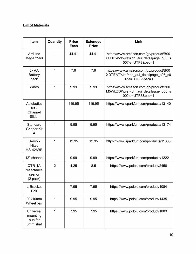
Bill of Materials
Item Quantity Price Each
Extended Price
Link
Arduino Mega 2560
1 44.41 44.41 https://www.amazon.com/gp/product/B006H0DWZW/ref=oh_aui_detailpage_o06_s
00?ie=UTF8&psc=1
6x AA Battery pack
1 7.9 7.9 https://www.amazon.com/gp/product/B00XDTEA7Y/ref=oh_aui_detailpage_o06_s0
0?ie=UTF8&psc=1
Wires 1 9.99 9.99 https://www.amazon.com/gp/product/B00M5WLZDW/ref=oh_aui_detailpage_o06_s
00?ie=UTF8&psc=1
Actobotics Kit
Channel Slider
1 119.95 119.95 https://www.sparkfun.com/products/13140
Standard Gripper Kit
A
1 9.95 9.95 https://www.sparkfun.com/products/13174
Servo Hitec
HS426BB
1 12.95 12.95 https://www.sparkfun.com/products/11883
12” channel 1 9.99 9.99 https://www.sparkfun.com/products/12221
QTR1A reflectance sesnor (2 pack)
2 4.25 8.5 https://www.pololu.com/product/2458
LBracket Pair
1 7.95 7.95 https://www.pololu.com/product/1084
90x10mm Wheel pair
1 9.95 9.95 https://www.pololu.com/product/1435
Universal mounting hub for
6mm shaf
1 7.95 7.95 https://www.pololu.com/product/1083
19
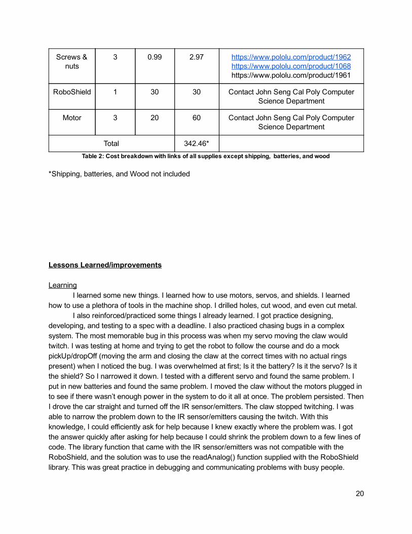
Screws & nuts
3 0.99 2.97 https://www.pololu.com/product/1962 https://www.pololu.com/product/1068 https://www.pololu.com/product/1961
RoboShield 1 30 30 Contact John Seng Cal Poly Computer Science Department
Motor 3 20 60 Contact John Seng Cal Poly Computer Science Department
Total 342.46* Table 2: Cost breakdown with links of all supplies except shipping, batteries, and wood
*Shipping, batteries, and Wood not included Lessons Learned/improvements Learning
I learned some new things. I learned how to use motors, servos, and shields. I learned how to use a plethora of tools in the machine shop. I drilled holes, cut wood, and even cut metal.
I also reinforced/practiced some things I already learned. I got practice designing, developing, and testing to a spec with a deadline. I also practiced chasing bugs in a complex system. The most memorable bug in this process was when my servo moving the claw would twitch. I was testing at home and trying to get the robot to follow the course and do a mock pickUp/dropOff (moving the arm and closing the claw at the correct times with no actual rings present) when I noticed the bug. I was overwhelmed at first; Is it the battery? Is it the servo? Is it the shield? So I narrowed it down. I tested with a different servo and found the same problem. I put in new batteries and found the same problem. I moved the claw without the motors plugged in to see if there wasn’t enough power in the system to do it all at once. The problem persisted. Then I drove the car straight and turned off the IR sensor/emitters. The claw stopped twitching. I was able to narrow the problem down to the IR sensor/emitters causing the twitch. With this knowledge, I could efficiently ask for help because I knew exactly where the problem was. I got the answer quickly after asking for help because I could shrink the problem down to a few lines of code. The library function that came with the IR sensor/emitters was not compatible with the RoboShield, and the solution was to use the readAnalog() function supplied with the RoboShield library. This was great practice in debugging and communicating problems with busy people.
20

Improvements I would use commercial RC car batteries as opposed to AA batteries. The AA batteries led to multiple problems.
The robot was slow The robot’s behavior was inconsistent throughout the life of the battery
The motors/arm moved differently at full battery life vs halfway vs almost dead (Hypothesis) The encoder was inconsistent. I had trouble getting the arm to rise and fall to
the exact same spot, but there were other groups who thought it was incredibly accurate. I think it’s possibly my poor battery choice at fault. This hypothesis is not tested
I know the first two bullet points are true because I plugged in someone else's RC car battery to see what would happen, and the robot went faster than it ever had. It couldn’t follow the line well with this new battery because it was like a new robot. All the little tweaks I made under the AA batteries were obsolete and it would have taken a lot of work to port over to the new battery. I discovered this ~10 hours before the competition, so I didn’t have time to fix it, but I wish I had used a nice battery from the start.
I would have liked to use more IR sensor/emitters. I started with 3, moved to 4 a day before the competition, and wish I had had more. The robot’s consistency broke down after the second lap because there was only one rear point visible to the robot. As a result, it was possible the robot thought it was ready to pickUp/dropOff when crooked. This is because the robot moves to pickUp/dropOff when the rear sensor sees black. With two rear sensors, I can move the robot on only when both see black, and this would allow the robot to consistently square itself with the pegs after multiple laps. Conclusion
This project was fun, successful, and rewarding. I achieved my goal of making a relatively consistent robot. It always got the first 4 rings, and almost always got the next 4 rings. However, by the third trip, it rarely got 4 rings. As mentioned in the improvements section, there were some things I could have done to improve its consistency past the second round trip, but it performed very well overall.
I finished around 5th place( 1 rank). I don’t know for sure because only places 13 were± officially announced. The robots consistency carried it to the top of the field where it was beaten by robots that were more consistent and also scored more points.
Consistency was incredibly important. My robot beat impressive robots going for high risk, high reward maneuvers (such as crossing the barrier to the Scoring Pegs #2), because their robots would fail to accomplish anything and get reset multiple times.
Finally, I learned a ton. I knew how to use an Arduino, but beyond that I knew nothing about robotics. Now I feel comfortable with motors, servos, shields, and linear motion. And if i’m ever doing side projects using all these new toys acquired from this project i’ll make sure to use a high quality battery.
21

References [1] Rules: https://docs.google.com/document/d/1rYSVdBPb6dNHQXfgRWYkEfzj00706zCozCtoAm_0bv4/pub Appendix Code: #include <Wire.h> #include <RoboShield.h> RoboShield roboShield(0); boolean offTrack = false, startup = true; unsigned int time_m; int state = 2, ring_encdr, turn_encdr; /* * state = 0: driving to center from dropoff pegs * state = 1: driving to pickup pegs from center * state = 2: picking up at pickup pegs * state = 3: driving to center from pickup pegs * state = 4: driving to dropoff pegs from center * state = 5: dropping off at dropoff pegs */ #define NUM_SENSORS 4 // number of sensors used #define NUM_SAMPLES_PER_SENSOR 4 // average 4 analog samples per sensor reading #define EMITTER_PIN 2 // emitter is controlled by digital pin 2 #define REFLECT_SENS_TURN 0 #define REFLECT_SENS_LEFT 1 #define REFLECT_SENS_RIGHT 2 #define REFLECT_SENS_BACK 3 #define ARM_DIST 860 #define RING_DIST 220 #define CLAW_OPEN 74 #define CLAW_CLOSE 124 #define WHITE 570 #define ARM_MOTOR 2 #define ARM_SPEED 35 #define LEFT_MOTOR 1 #define LEFT_FOR_SPEED 25 #define RIGHT_MOTOR 3 #define RIGHT_FOR_SPEED 20 #define LEFT_TURN_LEFT 20 #define RIGHT_TURN_LEFT 20 #define LEFT_TURN_RIGHT 20 #define RIGHT_TURN_RIGHT 20 #define TURN_RADIUS 625 #define BEFORE_TURN_DIST 300 unsigned int sensorValues[NUM_SENSORS]; void pickUpRings() int prevEncoderVal;
22

//pick up the rings roboShield.resetEncoder(0); roboShield.setMotor(ARM_MOTOR, ARM_SPEED); while(roboShield.readEncoder(0) < ARM_DIST) ; roboShield.setMotor(ARM_MOTOR, 0); roboShield.setServo(7, CLAW_CLOSE); roboShield.resetEncoder(0); roboShield.setMotor(ARM_MOTOR, 1* ARM_SPEED); time_m = millis(); while(roboShield.readEncoder(0) < ARM_DIST + 555 && millis() time_m < 4000) ; roboShield.setMotor(ARM_MOTOR, 0); prevEncoderVal = roboShield.readEncoder(1); roboShield.setMotor(LEFT_MOTOR, LEFT_TURN_LEFT); roboShield.setMotor(RIGHT_MOTOR, RIGHT_TURN_LEFT); while(roboShield.readEncoder(1) prevEncoderVal < TURN_RADIUS*3/2) ; sens_read(sensorValues); //while 1 sensor is on the white while(sensorValues[REFLECT_SENS_LEFT] < WHITE || sensorValues[REFLECT_SENS_RIGHT] < WHITE) sens_read(sensorValues); roboShield.setMotor(LEFT_MOTOR, LEFT_FOR_SPEED); roboShield.setMotor(RIGHT_MOTOR, RIGHT_FOR_SPEED); state = 3; void sens_read(unsigned int *vals) vals[0] = roboShield.getAnalog(0); vals[1] = roboShield.getAnalog(1); vals[2] = roboShield.getAnalog(2); vals[3] = roboShield.getAnalog(3); void dropOffRings() int prevEncoderVal; roboShield.setServo(7, CLAW_OPEN); roboShield.lcdPrintf("start motors"); //move car into state 0 prevEncoderVal = roboShield.readEncoder(1); roboShield.setMotor(LEFT_MOTOR, LEFT_TURN_LEFT); roboShield.setMotor(RIGHT_MOTOR, RIGHT_TURN_LEFT); while(roboShield.readEncoder(1) prevEncoderVal < TURN_RADIUS) ; sens_read(sensorValues); //while 1 sensor is on the white while(sensorValues[REFLECT_SENS_LEFT] < WHITE || sensorValues[REFLECT_SENS_RIGHT] < WHITE) sens_read(sensorValues);
23

roboShield.setMotor(LEFT_MOTOR, LEFT_FOR_SPEED); roboShield.setMotor(RIGHT_MOTOR, RIGHT_FOR_SPEED); state = 0; void drive() // read raw sensor values sens_read(sensorValues); if (!checkTurn()) if (sensorValues[REFLECT_SENS_LEFT] < WHITE) //off track too far to the left offTrack = true; //stop motors roboShield.setMotor(LEFT_MOTOR, 0); roboShield.setMotor(RIGHT_MOTOR, 0); //turn_encdr = roboShield.readEncoder(1); roboShield.setMotor(LEFT_MOTOR, LEFT_TURN_RIGHT); roboShield.setMotor(RIGHT_MOTOR, RIGHT_TURN_RIGHT); //N while(offTrack) sens_read(sensorValues); if(sensorValues[REFLECT_SENS_LEFT] > WHITE) //We are on track again offTrack = false; // ring_encdr = roboShield.readEncoder(1) turn_encdr; //set left motor to original speed roboShield.setMotor(LEFT_MOTOR, LEFT_FOR_SPEED); //start the right motor up roboShield.setMotor(RIGHT_MOTOR, RIGHT_FOR_SPEED); if (sensorValues[REFLECT_SENS_RIGHT] < WHITE) //off track too far to the right offTrack = true; //stop motors roboShield.setMotor(LEFT_MOTOR, 0); roboShield.setMotor(RIGHT_MOTOR, 0); // turn_encdr = roboShield.readEncoder(1); roboShield.setMotor(LEFT_MOTOR, LEFT_TURN_LEFT); roboShield.setMotor(RIGHT_MOTOR, RIGHT_TURN_LEFT); while(offTrack) sens_read(sensorValues); if(sensorValues[REFLECT_SENS_RIGHT] > WHITE) //We are on track again
24

offTrack = false; // ring_encdr = roboShield.readEncoder(1) turn_encdr; //set right motor to original speed roboShield.setMotor(RIGHT_MOTOR, RIGHT_FOR_SPEED); //start the left motor up roboShield.setMotor(LEFT_MOTOR, LEFT_FOR_SPEED); /* * state = 0: driving to center from dropoff pegs * state = 1: driving to pickup pegs from center * state = 2: picking up at pickup pegs * state = 3: driving to center from pickup pegs * state = 4: driving to dropoff pegs from center * state = 5: dropping off at dropoff pegs */ int ring_drive() // read raw sensor values sens_read(sensorValues); while(sensorValues[3] < WHITE) sens_read(sensorValues); if (sensorValues[REFLECT_SENS_LEFT] < WHITE) //off track too far to the left offTrack = true; //stop motors roboShield.setMotor(LEFT_MOTOR, 0); roboShield.setMotor(RIGHT_MOTOR, 0); turn_encdr = roboShield.readEncoder(1); roboShield.setMotor(LEFT_MOTOR, LEFT_TURN_RIGHT); roboShield.setMotor(RIGHT_MOTOR, RIGHT_TURN_RIGHT); //N while(offTrack) sens_read(sensorValues); roboShield.lcdClear(); roboShield.lcdPrintf("%d", sensorValues[3]); if(sensorValues[3] > WHITE) return 0; if(sensorValues[REFLECT_SENS_LEFT] > WHITE) //We are on track again offTrack = false; //set left motor to original speed roboShield.setMotor(LEFT_MOTOR, LEFT_FOR_SPEED);
25
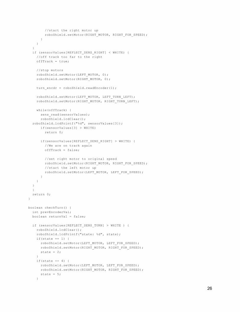
//start the right motor up roboShield.setMotor(RIGHT_MOTOR, RIGHT_FOR_SPEED); if (sensorValues[REFLECT_SENS_RIGHT] < WHITE) //off track too far to the right offTrack = true; //stop motors roboShield.setMotor(LEFT_MOTOR, 0); roboShield.setMotor(RIGHT_MOTOR, 0); turn_encdr = roboShield.readEncoder(1); roboShield.setMotor(LEFT_MOTOR, LEFT_TURN_LEFT); roboShield.setMotor(RIGHT_MOTOR, RIGHT_TURN_LEFT); while(offTrack) sens_read(sensorValues); roboShield.lcdClear(); roboShield.lcdPrintf("%d", sensorValues[3]); if(sensorValues[3] > WHITE) return 0; if(sensorValues[REFLECT_SENS_RIGHT] > WHITE) //We are on track again offTrack = false; //set right motor to original speed roboShield.setMotor(RIGHT_MOTOR, RIGHT_FOR_SPEED); //start the left motor up roboShield.setMotor(LEFT_MOTOR, LEFT_FOR_SPEED); return 0; boolean checkTurn() int prevEncoderVal; boolean returnVal = false; if (sensorValues[REFLECT_SENS_TURN] > WHITE ) roboShield.lcdClear(); roboShield.lcdPrintf("state: %d", state); if(state == 1) roboShield.setMotor(LEFT_MOTOR, LEFT_FOR_SPEED); roboShield.setMotor(RIGHT_MOTOR, RIGHT_FOR_SPEED); state = 2; if(state == 4) roboShield.setMotor(LEFT_MOTOR, LEFT_FOR_SPEED); roboShield.setMotor(RIGHT_MOTOR, RIGHT_FOR_SPEED); state = 5;
26

if (state == 0 || state == 3) //move past turn because turn sensor is not parallel with drive sensors prevEncoderVal = roboShield.readEncoder(1); while(roboShield.readEncoder(1) prevEncoderVal < BEFORE_TURN_DIST) ; //turn off motors roboShield.setMotor(LEFT_MOTOR, 0); roboShield.setMotor(RIGHT_MOTOR, 0); prevEncoderVal = roboShield.readEncoder(1); //Turn the car if (state == 0) //turn left roboShield.setMotor(LEFT_MOTOR, LEFT_TURN_LEFT); roboShield.setMotor(RIGHT_MOTOR, RIGHT_TURN_LEFT); while(roboShield.readEncoder(1) prevEncoderVal < TURN_RADIUS/2 + 70) ; sens_read(sensorValues); //while 1 sensor is on the white while(sensorValues[REFLECT_SENS_LEFT] < WHITE || sensorValues[REFLECT_SENS_RIGHT] < WHITE) sens_read(sensorValues); else if (state == 3) //turn right roboShield.setMotor(LEFT_MOTOR, LEFT_TURN_RIGHT); roboShield.setMotor(RIGHT_MOTOR, RIGHT_TURN_RIGHT); while(roboShield.readEncoder(1) prevEncoderVal < TURN_RADIUS/2 + 70) ; sens_read(sensorValues); //while 1 sensor is on the white while(sensorValues[REFLECT_SENS_LEFT] < WHITE || sensorValues[REFLECT_SENS_RIGHT] < WHITE) sens_read(sensorValues); if (state == 0) roboShield.setMotor(LEFT_MOTOR, LEFT_FOR_SPEED); roboShield.setMotor(RIGHT_MOTOR, RIGHT_FOR_SPEED); state = 1; if (state == 3) roboShield.setMotor(LEFT_MOTOR, LEFT_FOR_SPEED); roboShield.setMotor(RIGHT_MOTOR, RIGHT_FOR_SPEED); state = 4; returnVal = true; return returnVal;
27

void setup() delay(500); Serial.begin(9600); // set the data rate in bits per second for serial data transmission delay(1000); if (roboShield.buttonPressed()) roboShield.debuggingMode(); void loop() if(startup) roboShield.setMotor(LEFT_MOTOR, LEFT_FOR_SPEED); roboShield.setMotor(RIGHT_MOTOR ,RIGHT_FOR_SPEED); startup = false; switch(state) case 0: drive(); break; case 1: drive(); break; case 2: ring_drive(); roboShield.setMotor(RIGHT_MOTOR, 0); roboShield.setMotor(LEFT_MOTOR, 0); pickUpRings(); break; case 3: drive(); break; case 4: drive(); break; case 5: ring_drive(); roboShield.setMotor(RIGHT_MOTOR, 0); roboShield.setMotor(LEFT_MOTOR, 0); //move forward a little to drop off roboShield.resetEncoder(1); roboShield.setMotor(RIGHT_MOTOR, RIGHT_FOR_SPEED); roboShield.setMotor(LEFT_MOTOR, LEFT_FOR_SPEED); while(roboShield.readEncoder(1) < 80); dropOffRings(); break; default: roboShield.lcdClear(); roboShield.lcdPrintf("In default switch, BAADDDDD");
28

delay(300000);
29